Embed Size (px)
Citation preview
Indonesian Journal of Electrical Engineering and Computer Science Vol. 3, No. 1, July 2016, pp. 59 ~ 66 DOI: 10.11591/ijeecs.v3.i1.pp59-66 59
Received February 2, 2016; Revised May 25, 2016; Accepted June 10, 2016
Analysis of Step Up Transformer for Pulsed Electric Fields Generator
Yoppy*, Mohamad Khoirul Anam, Yudhistira, Priyo Wibowo, Harry Arjadi, Hutomo Wahyu Nugroho, Haryo Dwi Prananto
Research Center for Quality System and Testing Technology (P2SMTP) – LIPI Puspiptek Area Building 417, Tangerang Selatan, Indonesia
*Corresponding author, e-mail: [email protected]
Abstract Pulsed electric fields (PEF) is a novel non-thermal food processing whose purpose is inactivating
microbes while at the same time preserving food’s nutrition, color, and taste. This paper presents an analysis of step up transormer for PEF high voltage generator. To achieve the optimum PEF effects, the pulse shape should resemble a square, which is characterized by low voltage drop and fast rising time. Through simulations, it has been shown that higher transformer inductance results in lower voltage drop. However at some points, further increasing the inductance would only produces negligible improvements. Meanwhile fast rising time can be achieved by minimizing leakage inductance and parasitic capacitance. Moreover, maximum energy transfer to the load can be obtained by reducing winding resistances. Finally, a case of high voltage generator using ignition coil has been evaluated. Due to its high winding resistances, ignition coil seems to be not suitable for PEF applications.
Keywords: pulsed electric fields, non thermal food processing, step up tranformer
Copyright © 2016 Institute of Advanced Engineering and Science. All rights reserved.
1. Introduction One of conventional methods in food sterilization is using thermal processing. Although
this method is very efficient in destroying bacteria, it also has some disadvantages, for example potentially reducing nutritional content as welll as altering the color, taste, and aroma of the food. To overcome those drawbacks, non thermal food processing methods are developed, such as pulsed electric fields.
Pulsed electric fields (PEF) is basically short pulses of high voltage in order of tens of kilovolts applied to food. A PEF system consists of a treatment chamber where the food is placed. The chamber is usually small-sized and is connected to a pair of high voltage electrodes. When the voltage pulse is applied, a strong electric field of tens of kV/cm develops in the chamber. Such an intense electric shock causes the break down of microbe’s membrane. Because the applied voltage is short in duration, i.e in order of microseconds, temperature rise is insignificant. Therefore, sterilization purposes can be achieved while at the same time undesirable thermal side effects can be minimized.
Several investigations have been done to compare the results of thermal processing and PEF methods. By choosing an appropriate voltage and frequency, PEF method can result in the same level of bacteria inactivation as that of thermal processing. Additionally, PEF is better in preserving the food pH level [1]. Other studies compare the effect of PEF and thermal processing [2] as well as high pressure [3] in degrading bacteria PME (pectin methyl estarase) in orange juice. The studies suggest that PEF is more effective in bacteria inactivation, and therefore the orange juice has a longer shelf life. Resilience of bacteria against PEF treatment depends on the structure and size of the bacteria [4]. Besides that, the electric field applied in the treatment chamber also plays a major role. This includes the pulse width, total processing time, and amount of energy delivered to the food [5].
There has been several implemented methods to generate a high voltage, such as solid state Marx Generator that can produce pulse voltage up to 6 kV at 1.6 kA [1, 2]. Another technique is using pulse forming network (PFN) [8]. In order to obtain an ideal pulse ouput, the impedance of PFN should be equal to that of the load. So, the output of PFN is highly sensitive to the variation of load impedance [9]. A high voltage pulse can also be generated by using high
ISSN: 2502-4752
IJEECS Vol. 3, No. 1, July 2016 : 59 – 66
60
voltage capacitor banks and switching components, for instance solid state devices [10] and vacuum tubes [11]. Solid state devices such as IGBT or MOSFET is usually operating in low voltage. In order to switch a high voltage, several units of them need to be configured in series so that the voltage is shared equally among them. Because this is a difficult task to achieve [12], one device may fail due to overvoltage, and eventually the whole system will be damaged. On the other hand, vaccum tubes are generally less expensive and more robust than solid state devices. But vaccum tubes have several disadvantages, for instance high voltage drop, low switching speed, and requiring complex driving circuits.
Instead of switching on high voltage, switching can also be done on low voltage and then amplified using a step up transformer. A step up transformer based pulse generator is implemented in [12], and promising results have been demonstrated. The high voltage generator is switching voltages at 1000 VDC, and amplifying the voltage 12 times to produce a 12 kV output. In the implementation a few IGBTs are configured in parallel to handle high currents that exist on the primary windings. From load balancing point of view, parallel configuration is easier to be implemented compared to a series one. Inspite of the aforementioned advantages, a step up transformer based generator also comes with drawbacks, such as longer rise time and decreased energy efficiency [12].
According to previous studies as discussed above, effectiveness of PEF highly depends on the generated pulse shape [5]. Ideally the pulse shape should resemble a square, which is characterized by short rise time and low voltage drop [9]. In reality, a step up transformer will always comprise parasitic components [13] which are affecting the rise time and limiting the maximum output voltage. Moreover, magnetising inductance of the transformer plays important roles in determining the output voltage evolution over time. In order to design an effective PEF generator, it is crucial to understand the effects of those parameters on the output pulse, about which this paper aims to analyze and demonstrate. Characteristic equations of the circuits are derived, simulated and evaluated using Matlab. Finally, a case of high voltage generator using ignition coil is presented and evaluated. 2. Step Up Transformer Output
An ideal pulse shape for PEF application should be like a square because a minimum threshold voltage and minimum pulse duration are required for effectively destroying microbe’s cell membrane. Below the threshold level, energy delivered to the load will be dominantly transformed into heat instead of generating PEF destructive effects [7]. Consequenty, there will be significant temperature rise such that thermal effects become more pronounced, which actually is unexpected in PEF processing.
A number of investigations have shown that effective PEF requires that electric fields applied in the treatment chamber should be in the range of 20-50 kV/cm, pulse width between 1-10 µs [14], and energy of 50-1000 kJ/kg [15]. It is important that the energy from the high voltage source should be efficiently transfered to the load in the treatment chamber. Those output parameters are affected by various factors, such as magnetising inductance, parasitic components, and amount of energy available in capacitor banks.
2.1. Effect of Magnetising Inductance
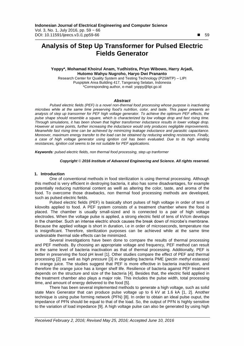
Elements of an ideal transformer are primary and secondary windings. These magnetising inductance have a role in determining the level of output voltage drop. Figure 1 shows the topology of a high voltage generator that use a step up tranformer. Initially, the switch is in open condition and capactor Cs is charged up to a certain level (the charging circuit is not shown in the figure). After Cs is fully charged, the switch is then closed and the energy stored in Cs is discharged to the transformer. As a result, a high voltage output with amplification of n (number of winding ratio) times will be available at the secondary winding. The advantage of using a step-up transformer is that the switching is done in low voltage levels.
Figure 1b describes the equivalent circuit of Figure 1a. Looking from the primary side the magnetizing inductance Lm is equal to Lpar, while the load resistance R is divided by n
2
which is denoted by RL. A parallel RLC circuit like Figure 1b has a characteristic equation defined as follow:
IJEECS ISSN: 2502-4752
Analysis of Step Up Transformer for Pulsed Electric Electric Fields Generator (Yoppy)
61
(1)
The circuit response is of either critically damped, underdamped, or overdamped,
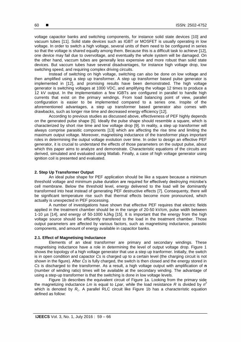
depending on the values of the components, as shown in Figure 2a. Cs and RL are deliberately given values of 500 µF and 0.1 Ω, respectively. Since in PEF applications the pulse width is usually up to 10 µs, we will evaluate this initial time span after discharging is started, which is shown in Figure 2b. The most striking feature is that the voltage immediately jump to the maximum value without any rising time, which is an ideal and desirable response. After that the voltage starts to decline gradually. It is observed that larger magnetizing inductance Lm results in lower voltage drop. However, it can also be seen that at some points, further increasing Lm does not proportionally reduce voltage drop.
RCS
switchStep-up
transformer
1:n
Lpar Lser
(a)
RL=R/n2
CS
switch
Lm
(b)
v
+
-
Figure 1. (a) Ideal Step-up Transformer based PEF Generator and (b) its Equivalent Circuits
(a) (b)
Figure 2. (a) Discharging Voltage Evolution and (b) The First 10 µs Window
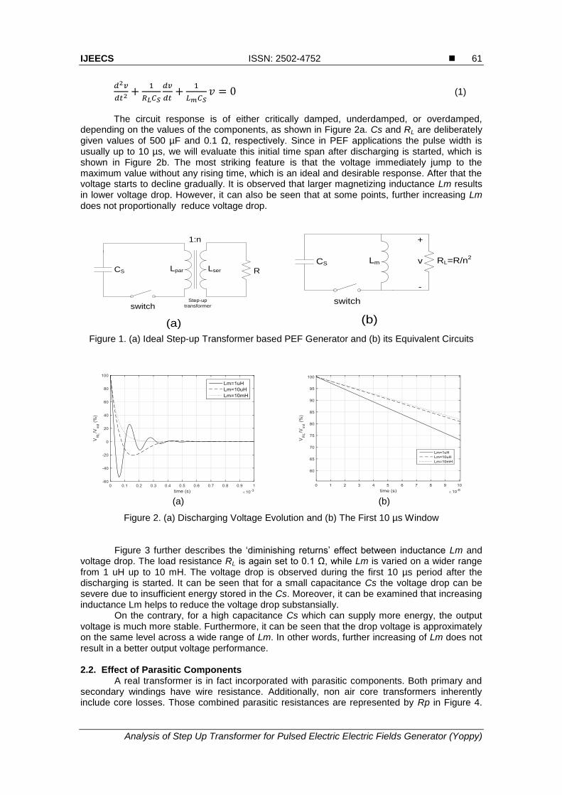
Figure 3 further describes the ‘diminishing returns’ effect between inductance Lm and voltage drop. The load resistance RL is again set to 0.1 Ω, while Lm is varied on a wider range from 1 uH up to 10 mH. The voltage drop is observed during the first 10 µs period after the discharging is started. It can be seen that for a small capacitance Cs the voltage drop can be severe due to insufficient energy stored in the Cs. Moreover, it can be examined that increasing inductance Lm helps to reduce the voltage drop substansially.
On the contrary, for a high capacitance Cs which can supply more energy, the output voltage is much more stable. Furthermore, it can be seen that the drop voltage is approximately on the same level across a wide range of Lm. In other words, further increasing of Lm does not result in a better output voltage performance.
2.2. Effect of Parasitic Components
A real transformer is in fact incorporated with parasitic components. Both primary and secondary windings have wire resistance. Additionally, non air core transformers inherently include core losses. Those combined parasitic resistances are represented by Rp in Figure 4.
ISSN: 2502-4752
IJEECS Vol. 3, No. 1, July 2016 : 59 – 66
62
Energy from primary windings is transferred to secondary windings by magnetic coupling. In reality, the magnetic coupling can never be perfect. Thus, there will be some amount of leakage inductance in the primary and secondary windings, which are simplified and represented by an inductance Lp [16].
Figure 3. Voltage Drop During the First 10 us with Varying Lm and Cs
Moreover, potential difference between layers in each windings creates the so called
distributed capacitance. Also, potential difference between windings produces inter-winding capacitance. These collective parasitic capacitances are symbolized by Cp. In the next sections we will discuss the undesired effects caused by those parasitic components.
RLCs
switch
Lm
Rp
Cp
Lp
(a)
RLCs
switch
Cp
Lp
(b)
Figure 4. (a) Non Ideal Step-Up Transformer PEF Generator and (b) Its Simplified Circuit
2.2.1. Effect of Parasitic Rp
Analysis of parasitic effects of Rp can be approached by replacing the energy source Cs in Figure 4a with a step voltage, which has a zero rise time and an infinite amount of energy. Figure 5 shows that the rising voltage has a slope, which is caused by Lp and Cp that will be discussed more detail in the next section. Rp specifically plays a role to limit the maximum voltage appeared on the load RL. The voltage that presents across the load RL after the transient period can be calculated by using voltage divider formula:
(2)
Consequently, the amount of energy delivered to the load RL is dependent on the resistance ratio between Rp and RL. It is desirable to minimize the resistance Rp so that as much energy as possible will be transfered to the load RL. 2.2.2. Effect of Parasitic Lp and Cp
During the risetime period, the magnetizing inductance Lm can be neglected as its effect is more pronounced after rising phase. Again, to analyze the risetime parameter, a step voltage is used to replace the Cs. In order to solely evaluate the effect of Lp and Cp, Rp is assumed zero resistance (see Figure 4b). Therefore, the transfer function of the circuit can be described as:

IJEECS ISSN: 2502-4752
Analysis of Step Up Transformer for Pulsed Electric Electric Fields Generator (Yoppy)
63
( )
(3)
Figure 5. Step Response Showing the Effect of Varying Rp, with RL is Fixed at 0.1 Ω
From Equation (1) it can be derived that the neper frequency (α), natural frequency (ω0), and damping factor (ζ) are as follow:
(4)
√ (5)
√
(6)
In general, decreasing Lp and Cp as well as increasing RL will result in a faster rise
time. This is evident in Figure 6, which shows the step response of some arbitrary values of Lp and Cp, with RL=10 Ω. A system with damping factor ζ<1, which is underdamped, usually has a faster rise time, but it also comes with overshoots. Excessive overshoot is usually avoided as it may produce stability problems.
Figure 6. Step Response Showing the Effect of Lp and Cp
Not only slowing the rise time, the presence of Lp and Cp can also cause the maximum voltage never be reached. This may happen under heavy load conditions. Referring to the
ISSN: 2502-4752
IJEECS Vol. 3, No. 1, July 2016 : 59 – 66
64
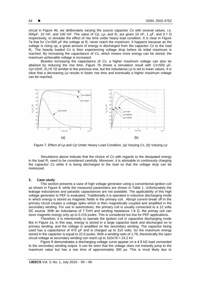
circuit in Figure 4b, we deliberately varying the source capacitor Cs with several values, i.e. 500µF, 10 mF, and 100 mF. The value of Cp, Lp, and RL are given 10 nF, 1 µF, and 0.1 Ω respectively, to simulate the effect of rise time under heavy load condition. It is clear in Figure 7a that for Cs=500 µF the voltage at RL never reach the maximum. It happens because as the voltage is rising up, a great amount of energy is discharged from the capacitor Cs to the load RL. The heavily loaded Cs is then experiencing voltage drop before its initial maximum is reached. By increasing the capacitance of Cs, which means more energy can be stored, the maximum achievable voltage is increased.
Besides increasing the capacitance of Cs, a higher maximum voltage can also be attained by reducing the rise time. Figure 7b shows a simulation result with Cs=500 µF, Cp=10nF, RL=0.1Ω similiar to the previous one, but the inductance Lp is set to lower values. It is clear that a decreasing Lp results in faster rise time and eventually a higher maximum voltage can be reached.
(a) (b)
Figure 7. Effect of Lp and Cp Under Heavy Load Condition, (a) Varying Cs, (b) Varying Lp
Simulations above indicate that the choice of Cs with regards to the dissipated energy in the load RL need to be considered carefully. Moreover, it is advisable to continously charging the capacitor Cs while it is being discharged to the load so that the voltage drop can be minimized.
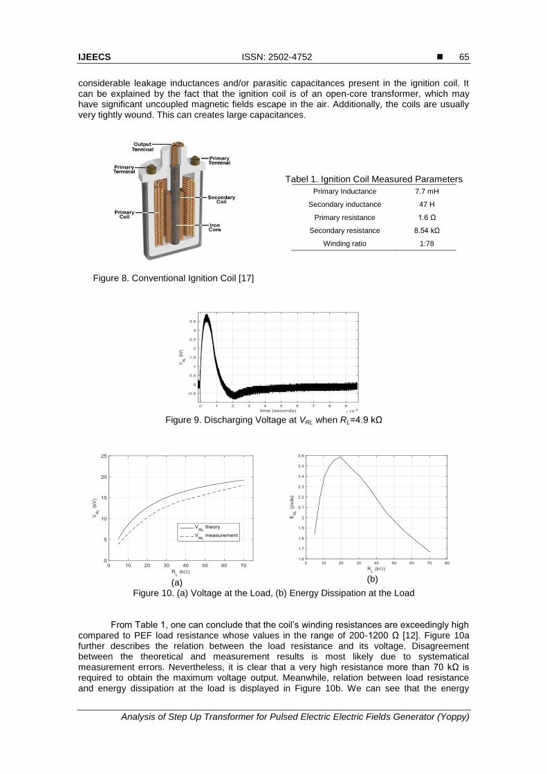
3. Case study This section presents a case of high voltage generator using a conventional ignition coil
as shown in Figure 8, while the measured parameters are shown in Table 1. Unfortunately the leakage inductances and parasitic capacitances are not available. The applicability of this high voltage generator in PEF is evaluated. Traditionally it is operated in inductive discharging mode in which energy is stored as magnetic fields in the primary coil. Abrupt current break off in the primary circuit creates a voltage spike which is then magnetically coupled and amplified in the secondary winding. For use in automotives, the primary coil is usually connected to a 12 volts DC source. With an inductance of 7.7mH and winding resistance 1.6 Ω, the primay coil can store magnetic energy only up to 0.216 joules. This is considered too low for PEF applications.
Therefore, it is intentionally to operate the ignition coil in capacitive discharging mode like in Figure 1a. In this way, energy is stored in a large capacitor bank and discharged on to primary winding, and the voltage is amplified on the secondary winding. The capacitor being used has a capacitance of 470 µF and is charged up to 310 volts. So the maximum energy stored in the capacitor is equal to 22.6 joules. With a winding ratio of 1:78, theoretically the open circuit voltage at secondary winding can reach up to 310x78 = 24,2 kV.
Figure 9 demonstrates a discharging voltage curve appear on a 4.9 kΩ load connected to the secondary winding output. It can be seen that the voltage does not instantly jump to the maximum value but has a rise time of approximately 300 µs. This is most likely due to
IJEECS ISSN: 2502-4752
Analysis of Step Up Transformer for Pulsed Electric Electric Fields Generator (Yoppy)
65
considerable leakage inductances and/or parasitic capacitances present in the ignition coil. It can be explained by the fact that the ignition coil is of an open-core transformer, which may have significant uncoupled magnetic fields escape in the air. Additionally, the coils are usually very tightly wound. This can creates large capacitances.
Figure 8. Conventional Ignition Coil [17]
Tabel 1. Ignition Coil Measured Parameters
Primary Inductance 7.7 mH
Secondary inductance 47 H
Primary resistance 1.6 Ω
Secondary resistance 8.54 kΩ
Winding ratio 1:78
Figure 9. Discharging Voltage at VRL when RL=4.9 kΩ
(a)
(b)
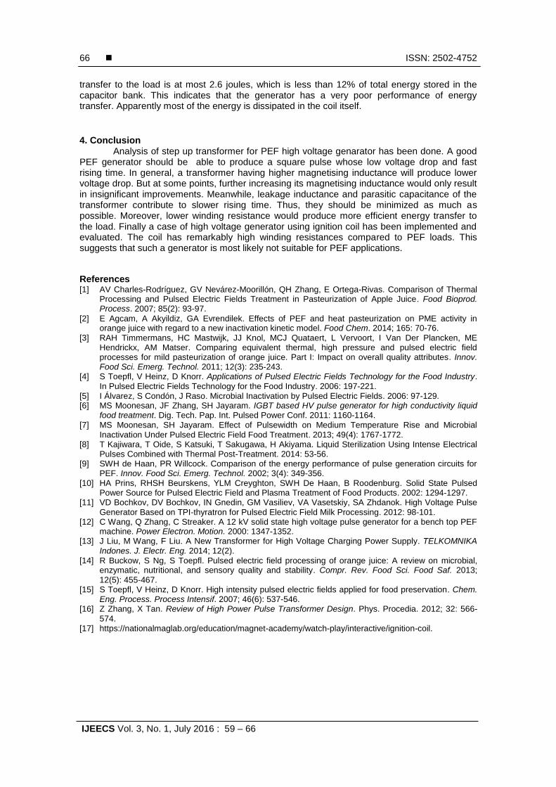
Figure 10. (a) Voltage at the Load, (b) Energy Dissipation at the Load From Table 1, one can conclude that the coil’s winding resistances are exceedingly high
compared to PEF load resistance whose values in the range of 200-1200 Ω [12]. Figure 10a further describes the relation between the load resistance and its voltage. Disagreement between the theoretical and measurement results is most likely due to systematical measurement errors. Nevertheless, it is clear that a very high resistance more than 70 kΩ is required to obtain the maximum voltage output. Meanwhile, relation between load resistance and energy dissipation at the load is displayed in Figure 10b. We can see that the energy
ISSN: 2502-4752
IJEECS Vol. 3, No. 1, July 2016 : 59 – 66
66
transfer to the load is at most 2.6 joules, which is less than 12% of total energy stored in the capacitor bank. This indicates that the generator has a very poor performance of energy transfer. Apparently most of the energy is dissipated in the coil itself.
4. Conclusion
Analysis of step up transformer for PEF high voltage genarator has been done. A good PEF generator should be able to produce a square pulse whose low voltage drop and fast rising time. In general, a transformer having higher magnetising inductance will produce lower voltage drop. But at some points, further increasing its magnetising inductance would only result in insignificant improvements. Meanwhile, leakage inductance and parasitic capacitance of the transformer contribute to slower rising time. Thus, they should be minimized as much as possible. Moreover, lower winding resistance would produce more efficient energy transfer to the load. Finally a case of high voltage generator using ignition coil has been implemented and evaluated. The coil has remarkably high winding resistances compared to PEF loads. This suggests that such a generator is most likely not suitable for PEF applications.
References [1] AV Charles-Rodríguez, GV Nevárez-Moorillón, QH Zhang, E Ortega-Rivas. Comparison of Thermal
Processing and Pulsed Electric Fields Treatment in Pasteurization of Apple Juice. Food Bioprod. Process. 2007; 85(2): 93-97.
[2] E Agcam, A Akyildiz, GA Evrendilek. Effects of PEF and heat pasteurization on PME activity in orange juice with regard to a new inactivation kinetic model. Food Chem. 2014; 165: 70-76.
[3] RAH Timmermans, HC Mastwijk, JJ Knol, MCJ Quataert, L Vervoort, I Van Der Plancken, ME Hendrickx, AM Matser. Comparing equivalent thermal, high pressure and pulsed electric field processes for mild pasteurization of orange juice. Part I: Impact on overall quality attributes. Innov. Food Sci. Emerg. Technol. 2011; 12(3): 235-243.
[4] S Toepfl, V Heinz, D Knorr. Applications of Pulsed Electric Fields Technology for the Food Industry. In Pulsed Electric Fields Technology for the Food Industry. 2006: 197-221.
[5] I Álvarez, S Condón, J Raso. Microbial Inactivation by Pulsed Electric Fields. 2006: 97-129. [6] MS Moonesan, JF Zhang, SH Jayaram. IGBT based HV pulse generator for high conductivity liquid
food treatment. Dig. Tech. Pap. Int. Pulsed Power Conf. 2011: 1160-1164. [7] MS Moonesan, SH Jayaram. Effect of Pulsewidth on Medium Temperature Rise and Microbial
Inactivation Under Pulsed Electric Field Food Treatment. 2013; 49(4): 1767-1772. [8] T Kajiwara, T Oide, S Katsuki, T Sakugawa, H Akiyama. Liquid Sterilization Using Intense Electrical
Pulses Combined with Thermal Post-Treatment. 2014: 53-56. [9] SWH de Haan, PR Willcock. Comparison of the energy performance of pulse generation circuits for
PEF. Innov. Food Sci. Emerg. Technol. 2002; 3(4): 349-356. [10] HA Prins, RHSH Beurskens, YLM Creyghton, SWH De Haan, B Roodenburg. Solid State Pulsed
Power Source for Pulsed Electric Field and Plasma Treatment of Food Products. 2002: 1294-1297. [11] VD Bochkov, DV Bochkov, IN Gnedin, GM Vasiliev, VA Vasetskiy, SA Zhdanok. High Voltage Pulse
Generator Based on TPI-thyratron for Pulsed Electric Field Milk Processing. 2012: 98-101. [12] C Wang, Q Zhang, C Streaker. A 12 kV solid state high voltage pulse generator for a bench top PEF
machine. Power Electron. Motion. 2000: 1347-1352. [13] J Liu, M Wang, F Liu. A New Transformer for High Voltage Charging Power Supply. TELKOMNIKA
Indones. J. Electr. Eng. 2014; 12(2). [14] R Buckow, S Ng, S Toepfl. Pulsed electric field processing of orange juice: A review on microbial,
enzymatic, nutritional, and sensory quality and stability. Compr. Rev. Food Sci. Food Saf. 2013; 12(5): 455-467.
[15] S Toepfl, V Heinz, D Knorr. High intensity pulsed electric fields applied for food preservation. Chem. Eng. Process. Process Intensif. 2007; 46(6): 537-546.
[16] Z Zhang, X Tan. Review of High Power Pulse Transformer Design. Phys. Procedia. 2012; 32: 566-574.
[17] https://nationalmaglab.org/education/magnet-academy/watch-play/interactive/ignition-coil.


![Inelastic Design Spectra _Newmark Hall Design Spectra_[Yoppy Soleman, 2006]](https://img.pdfslide.net/doc/110x75/55721345497959fc0b91f9a1/inelastic-design-spectra-newmark-hall-design-spectrayoppy-soleman-2006.jpg)