Embed Size (px)
Citation preview
Analysis of stress on a fixed partial denture with a blade-vent implant abutment
Noriaki Takahashi, D.D.S.,” Tetsuya Kitagami, D.D.S., Ph.D.,**. and Tomio Komori, D.D.S., Ph.D.*** Osaka Dental University, Osaka, Japan
D ental implants are being used more frequently, with many histologic studies having been reported,‘-’
but only a few studies have been made that deal with physical problems. Yet more importance should be
given to investigations dealing with physical forces
that stabilize dental implants in a functional state. Tesk and associates’ reported stress distribution in the bone arising from loading on endosteal implants,
and Weinstein and associates” reported stress anal- ysis of porous rooted implants. However, there is no
literature on stress analysis of dental implants with superstructures.
A study of stress distribution of dental implants imbedded in the bone is described, with special
reference to the model mandibular posterior fixed partial denture constructed on a natural tooth and a
blade-vent implant abutment. The results were compared with the findings of a fixed partial denture
constructed on two natural tooth abutments. A finite element method was employed for a stress
analysis. This method was invented to analyze aero- nautical structures in 1956,” and it has been a part of
many reports about mechanical problems in dental restorations.
MATERIALS AND METHODS
A blade-vent implant was imbedded at the site of the mandibular second molar, and a fixed partial
denture was constructed on the second premolar and the molar implant abutments. As a control a fixed partial denture was constructed on the second premolar and the second molar; each pontic was a sanitary type. The size of the abutment tooth and the thickness of the periodontium and periimplan-
*Senior, Graduate School of Osaka Dental University. **Assistant Professor, Department of Prosthodontics. ***Professor, Department of Prosthodontics.
tium were based on the previous literature.‘.” The
thickness of the periodontium was 0.4 mm at the cervical part, 0.2 mm at the mid part, and 0,25-0.30
mm at the apical part. The thickness of the periim- plantium was 0.4 mm. It was assumed that the bone
was isotropic and homogeneous.
A finite element model of the fixed partial denture constructed on the second premolar and implant
abutments consisted of 428 triangular elements and 259 nodal points (implant fixed partial denture) (Fig. 1). A model of the fixed partial denture
constructed on the second premolar and the second molar abutments consisted of 342 triangular
elements and 212 nodal points (natural tooth fixed partial denture) (Fig. 2).
The physical properties of each material, based on the previous literature, are given in Table I.“‘-” It
was considered that the peripheral lines of the bone were fixed for support. A vertical load and an
inclined load 45 degrees distal to the vertical axis were created at the pontic with a 1 kg weight.
Deflections and stresses under each condition were computed mathematically with a two-dimensional finite element method.
RESULTS
The deffection field of the implant fixed partial
denture under the vertical load is seen in Fig. 3. The fixed partial denture unit was depressed by loading.
A principal stress distribution under the same eondi- tion is shown in Fig. 4. Stress concentration was
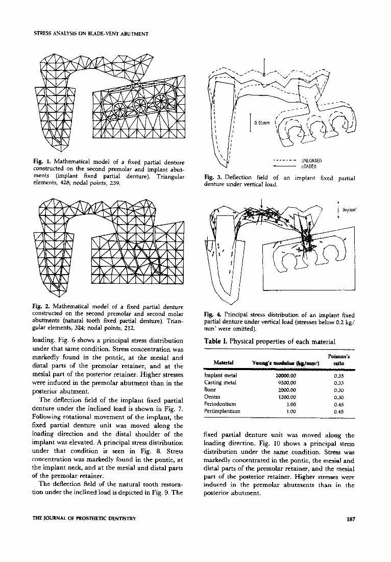
markedly found in the pontic, at the implant neck, and at the mesial and distal parts of the premolar retainer. Stresses below 0.2 kg/mm2 were omitted in all principal stress distribution figures.
The deflection field of the natural tooth fixed partial denture under the vertical load is seen in Fig. 5. The fixed partial denture unit was depressed by
186 AUGUST 1978 VOLUME 40 NUMBER 2 0022-3913/78/024M)1~~.~/OQ 1978 The C. V. Mosty Co.
STRESS ANALYSIS ON BLADE-VENT ABUTMENT
Fig. 1. Mathematical model of a fixed partial denture constructed on the second premolar and implant abut- ments (implant fixed partial denture). Triangular elements, 428; nodal points, 259.
Fig. 2. Mathematical model of a fixed partial denture constructed oh the second premolar and second molar abutments (natural tooth fixed partial denture). Trian- gular elements, 324; nodal points, 212.
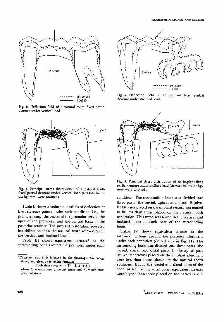
loading. Fig. 6 shows a principal stress distribution under that same condition. Stress concentration was markedly found in the pontic, at the mesial and distal parts of the premolar retainer, and at the mesial part of the posterior retainer. Higher stresses were induced in the premolar abutment than in the posterior abutment.
The deflection field of the implant fixed partial denture under the inclined load is shown in Fig. 7. Following rotational movement of the implant, the fixed partial denture unit was moved along the loading direction and the distal shoulder of the implant was elevated. A principal stress distribution under that condition is seen in Fig. 8. Stress concentration was markedly found in the pontic, at the implant neck, and at the mesial and distal parts of the premolar retainer.
The deflection field of the natural tooth restora- tion under the inclined load is depicted in Fig. 9. The
VI ‘\ ’ ------- UNLOADED
- LOADED
Fig. 3. Deflection field of an implant fixed partial denture under vertical load.
Fig. 4. Principal stress distribution of an implant fixed partial denture under vertical load (stresses below 0.2 kg/ mm2 were omitted).
Table I. Physical properties of each material
M&&d
Implant metal
Casting metal Bone Dentin Periodontium Periimplantium
FObSOI?‘S
Y4l&S “) rath,
2oooo.00 0.33
9500.00 0.33
2oc!o.00 0.30
1200.00 0.30
1.00 0.45
1.00 0.45
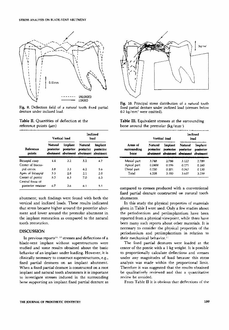
fixed partial denture unit was moved along the loading direction. Fig. 10 shows a principal stress distribution under the same condition, Stress was markedly concentrated in the pontic, the me&al and distal parts of the premolar retainer, and the mesial part of the posterior retainer. Higher stresses were induced in the premolar abutments than in the posterior abutment.
THE JOURNAL OF FROSTHETJC DENTISTRY 187
TAKAHASHI, KITAGAMI, AND KOMORI
Fig. 5. Deflection field of a natural tooth fixed partial denture under vertical load.
Fig. 6. Principal stress distribution of a natural tooth fixed partial denture under vertical load (stresses below 0.2 kg/mm2 were omitted).
Table II shows absolute quantities of deflection at five reference points under each condition, i.e., the
premolar cusp, the center of the premolar cervix, the apex of the premolar, and the central fossa of the
posterior retainer. The implant restoration revealed less deflection than the natural tooth restoration in the vertical and inclined load.
Table III shows equivalent stresses* at the surrounding bone around the premolar under each
*Equidmt stress: It is f&wed by the shearing-strain energy theory and given by following formula:
Equivalent stress = J(S: - S, S, + S:) where S, = maximum principal stress and S, = minimum principal stress.
\ \ I U ------- UNLOADED - LOADED
Fig. 7. Deflection field of an implant fixed partial denture under inclined load.
Fig. 8. Principal stress distribution of an implant fixed partial denture under inclined load (stresses below 0.2 kg/ mm’ were omitted).
condition. The surrounding bone was divided into three parts-the mesial, apical, and distal. Equiva-
lent stresses placed on the implant restoration tended to be less than those placed on the natural tooth
restoration. This trend was found in the vertical and inclined loads at each part of the surrounding bone.
Table IV shows equivalent stresses at the surrounding bone around the posterior abutment
under each condition (dotted area in Fig. 11). The surrounding bone was divided into three parts-the mesial, apical, and distal parts. In the apical part equivalent stresses placed on the implant abutment were less than those placed on the natural tooth abutment. But in the mesial and distal parts of the bone, as well as the total bone, equivalent stresses were higher than those placed on the natural tooth
188 : AUGUST 1978 VOLUME 40 NUMBER 2
STRESS ANALYSIS ON BLADE-VENT ABUTMENT
Fig. 9. Deflection field of a natural tooth fixed partial denture under inclined load.
Table II. Quantities of deflection at the Table III. Equivalent stresses at the surrounding reference points (pm) bone around the premolar (kg/mm’)
Reference points
Inclined Vertical load load
Natural Implant Natural Implant posterior posterior posterior posterior abutment abutment abutment abutment
Inclined Vertical load load
Areas of Natural Implant Natural Implant surrounding posterior poswior posterior posterior
bone dw&ment abutment t abutarent
Bicuspid cusp 4.4 3.2 5.2 4.7 Center of biscus-
pid cervix 3.8 3.5 6.2 5.6 Apex of bicuspid 3.5 2.8 2.1 2.0 Center of pontic 8.3 6.3 7.0 6.3 Central fossa of
posterior retainer 6.7 3.6 6.1 5.1
abutment; such findings were found with both the vertical and inclined loads. These results indicated
that stress became higher around the posterior abut-
ment and lower around the premolar abutment in
the implant restoration as compared to the natural tooth restoration.
DISCUSSION
In previous reports 13. ‘-I stresses and deflections of a blade-vent implant without superstructures were studied and some results obtained about the basic behavior of an implant under loading. However, it is
clinically necessary to construct superstructures, e.g., fixed partial dentures on an implant abutment.
When a fixed partial denture is constructed on a root implant and natural tooth abutments it is important to investigate stresses induced in the surrounding bone supporting an implant fixed partial denture as
Fig. 10. Principal stress distribution of a natural tooth fixed partial denture under inclined load (stresses below 0.2 kg/mm? were omitted).
Mesial part 3.748 2.786 3.123 2.789 Apical part 0.2400 0.196 0.171 0.160 Distal part 0.220 0.201 0.343 0.130
Total 4.208 3.183 3.637 3.259
compared to stresses produced with a conventional fixed partial denture constructed OR natural tooth
abutments.
In this study the physical properties of materials
given in Table I were used. Only a few studies about the periodontium and periimplantium have been
reported from a physical viewpoint, while there have
been many such reports about other materials. It is necessary to consider the physical properties of the
periodontium and periimplantium in relation to their mechanical behavior.‘”
The fixed partial dentures were loaded at the center of the pontic with a 1 kg weight. It is possible
to proportionally calculate deflections and stresses under any magnitudes of load because this stress
analysis was made within the proportional limit. Therefore it was suggested that the results obtained be qualitatively reviewed and that a quantitative review be avoided.
From Table II it is obvious that deflections of the
THE JOURNAL OF PROSTHETIC DENTISTRY 189
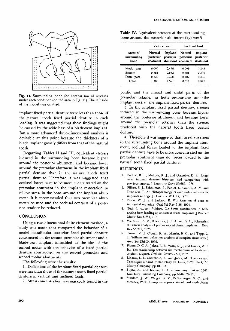
Fig, 11. Surrounding bone for comparison of stresses under each condition (dotted area in Fig. 11). The left side of the model was omitted.
implant fixed partial denture were less than those of
the natural tooth fixed partial denture in each loading. It was suggested that these findings might
be caused by the wide base of a blade-vent implant.
But a more advanced three-dimensional analysis is desirable at this point because the thickness of a
blade implant greatly differs from that of the natural
tooth.
Regarding Tables II and III, equivalent stresses induced in the surrounding bone became higher around the posterior abutment and became lower
around the premolar abutment in the implant fixed
partial denture than in the natural tooth fixed partial denture. Therefore it was suggested that
occlusal forces have to be more concentrated on the premolar abutment in the implant restoration to
relieve stress in the bone around the implant abut- ment. It is recommended that two premolar abut-
ments be used and the occlusal contacts of a poste- rior retainer be reduced.
CONCLUSION
Using a two-dimensional finite element method, a
study was made that compared the behavior of a model mandibular posterior fixed partial denture constructed on the second premolar abutment and a
blade-vent implant imbedded at the site of the second molar with the behavior of a fixed partial denture constructed on the second premolar and second molar abutments.
The following were the results: 1. Deflections of the implant fixed partial denture
were less than those of the natural tooth fixed partial denture in vertical and inclined loads.
2. Stress concentration was markedly found in the
TAKAHASHI, KITAGAMI, AND KOMOKI
Table IV. Equivalent stresses at the surrounding
bone around the posterior abutment (kg/mm’)
Vertical load inclined load
Areas of Natural Implant Natural Implant surrounding posterior posterior posterior posterior
bone abutment abutment abutment abutment
Mesial part 0.090 0.436 0.098 0.245
Bottom 0.861 0.665 0.406 0.304
Distal part 0.229 0.490 0.107 0.236
Total 1.180 1.591 0.611 0.875
pontic and the mesial and distal parts of the
premolar retainer in both restorations and the
implant neck in the implant fixed partial denture. 3. In the implant fixed partial denture, stresses
induced in the surrounding bone became higher
around the posterior abutment and became lower around the premolar retainer than the stresses
produced with the natural tooth fixed partial
denture.
4. Therefore it was suggested that, to relieve stress to the surrounding bone around the implant abut-
ment, occlusal forces loaded to the implant fixed partial denture have to be more concentrated on the
premolar abutment than do forces loaded to the natural tooth fixed partial denture.
REFERENCES
1.
2.
3.
4
5
6
7.
8.
9.
18.
Bodine, R. L., Melrose, R. J., and Grenoble, D. E.: Long- term implant denture histology and comparison with previous reports. J PROSTHET DENT 35:665, 1976. Piliero, S. J., Schnitman, P., Pentel, L., Cranin, A. N., and Dennison, ‘P. A.: Histopathology of oral endosteal metallic implants in dogs. J Dent Res 52:1117, 1973. Peters, W. J., and Jackson, R. W.: Reaction of bone to implanted materials. Oral Sci Rev 5:56, 1974. Tesk, J. A., and Widera, 0.: Stress distribution in bone arising from loading on endosteal dental implants. J Biomed Mater Res 4:251, 1973. Weinstein, A. M., Klawitter, J. J., Anand, S. C., Scheussler, R.: Stress analysis of porous rooted dental implants. J Dent Res 55:772, 1976. Turner, M. J., Clough, R. W., Martin, H. C., and Topp, I,. J.: Stiffness and deflection analysis of complex structures. J Aero Sci 23:805, 1956.
Picton, D. C. A., Johns, R. B., Wills, D. J., and Davies, W. I. R.: The relationship between the mechanisms of tooth and implant support. Oral Sci Reviews 5:3, 1974. Linkow, L. I., Chercheve, R., and Jones, M.: Theories and Techniques of Oral Implantology. St. Louis, 1970, The C. V. Mosby Company, pp 81-133. Fujita, K., and Kirino, T.: Oral Anatomy. Tokyo, 1967, Kanehara Publishing Company, pp 60-62, 74-87. Stanford, J. W., Weigel, K. V., Paffenbarger, G. C., and Sweeney, W. T.: Compressive properties of hard tooth tissues
AUGUST1978 VOLUME40 NUMBER2
STRESS ANALYSIS ON BLADE-VENT ABUTMENT
and some restorative materials. J Am Dent Assoc 60:746,
1960. 11. Howen, R. I.., and Rodriguez, M. S.: Tensile strength and
modulus of elasticity of tooth structure and several restora- tive materials. J Am Dent ALVOC 64:378, 1962.
12. Smith. 1). C.: Materials used for construction and fixation of implants. Oral Sci Rev 523, 1974.
13. Komori, T., Kitagami, ‘I‘.. Takahashi, N., Tsuji, I., Amari, M., Taniguchi, T., and Otani, M.: Stress analysis of blade
implant. J Osaka Odont Sot 39:810, 1976. 14. Komori, T., Kitagami, T., Takahashi, N., Suese, K., Amari,
M., Sakaguchi, K., and Suginaka, K.: Stress analysis of
blade implant. J Osaka Odont Sot 4&l 12: 1977. 15. Huang, H. K., and Ledley, R. S.: Numerical experiments
with a linear force-displacement tooth model. ,I Dent Res 48:X?, 1969.
Rcprmt requests to. DR. N~RIAKI TAKAHASEU
l-47 KYCBASHI
HIGASHI-KU
OSAKA, JAPAN
ARTICLES TO APPEAR IN FUTURE ISSUES
The &ect of oral hygiene on stomatitis in patients receiving cancer
S. F. Lindquist, D.D.S., A. J. Hickey, D.M.D., and J. B. Drane, D.D.S.
Obturator-overdentures retained by nonrigid attachments Michael MacEntee, L.D.S.
Hlstul@c evaluation of electrosurgery with varying frequency and waveform W. L. Maness, D.D.S., MS., F. W. Rober, B.S., R. E. Clark, Ph.D., E. Cataldo, D.D.S., D. Riis, D.M.D., and A. W. Haddad, D.M.D.
Facial pains and anxiety levels: Considerations for treatment Joseph J. Marbach, D.D.S., James A. Lipton, D.D.S., Pamela B. Lund, M.A., Frances Delahanty, Ph.D., and Terry Blank, D.D.S.
Geriatric dentistry: The problem Maury Massler, D.D.S., M.S.
Mechanical properties of tissue conditioners. Part II: Creep characteristics J. A. McCarthy, D.D.Sc., and J. B. Moser, M.S., Ph.D.
A new me&ceramic crown John W. McLean, O.B.E., D.Sc., M.D.%, L.D.S., Edmund E. Jeansonne, D.D.S., Howard Bruggers, D.D.S., and David B. Lynn, D.D.S.
THE JOURNAL OF PROSTHETK DENTISTRY 191