Embed Size (px)
Citation preview

Analysis of Trusses using SAP2000 Introduction Manual
Prepared by:
Abdellah Ait Elmouden
Gabriella Sampaio

This manual introduces you to SAP2000. The step-by-step instructions guide you through
development of your first model. The intent is to demonstrate the fundamentals and to show how
quickly and easily a model can be created using the program. Completing the tutorial will give
you hands-on experience working with SAP2000, which for most people is the quickest way to
become familiar with the program.
What is SAP2000?
SAP2000 is a general purpose finite element program which performs the static or dynamic,
linear or nonlinear analysis of structural systems. It is also a powerful design tool to design
structures following AASHTO specifications, ACI and AISC building codes. These features, and
many more make SAP2000 the state-of-the-art in structural analysis program.
The SAP2000 graphic user interface (GUI) is used to model, analyze, design, and display the
structure geometry, properties and analysis results. The analysis procedure can be divided into
three parts:
1. Preprocessing.
2. Solving.
3. Postprocessing
Part I Preprocessing:
In preprocessing, the following information is needed by SAP2000.
1. Choosing the units for this project.
2. Setting up geometry.
3. Defining material and member section properties.
4. Assigning member section properties and element releases.
5. Defining load cases.
6. Assigning load magnitudes.
7. Assigning restraints.
PART II Solving In this part SAP2000 will assemble and solve the global matrix.
PART III Postprocessing.
The main options in postprocessing are:
1. Displaying the deformed shape.
2. Displaying the member forces.
3. Printing the results.
4. Designing the structural members and checking the safety of a design.

5. Modifying the structure.
Exercice 1: Analysis of Simple Truss Structure using SAP2000
The following exercise illustrates the joint equilibrium method for a simple truss.
Solve using SAP2000: Determine the force in members AB and AC shown in this figure.
Given that the angle of member AC with the vertical is equal 60°, while the angle formed by
member AB and the vertical direction is equal 90°. The weight applied is w=100lb. State
whether is in tension or compression.
In order to solve the problem joint A may be isolated (method of joint). Observe that at this joint
there is an externally applied force of 100-lb which is vertical and pulls down on the joint. On
the other hand, member AC is pulling up on the joint trying to keep it from moving from its
original position. Similarly, member AB also applies a force on the joint in order to keep it from
moving from its original position.
The structure shown in the figure above is formed by truss members that can only carry forces
along the longitudinal axes of the members, then the force in member AC will be directed from
point A to point C. Similarly the force in member AB will be directed along the axis of AB.
The forces in these members can be calculated using the joint equilibrium method at joint A in
that the horizontal components of the forces applied at the joint must cancel each other and the
vertical components of the forces applied on the joint must also cancel each other. That is the
condition of equilibrium of forces, ΣFX = 0 and ΣFy= 0, must be satisfied at joint A.

Solve the problem using SAP2000 About SAP2000 v17 : The Software is available to all engineering students during open lab hours (Room E344). You can also download an evaluation version from http://www.csiamerica.com
Step 1: Begin a New Model Start SAP2000 from File menu > New Model command or the New Model button.
- Unit: The form shown in Figure will display. Verify that the default units are set to lb, in, F.
When a new model is started, SAP2000 will ask the user to specify a set of units. Those units become the “base units” for the model.
Grid Spacing - Determine the appropriate number of grid line and grid spacing to locate the joints of the
truss. Click on Grid only from the set of templates.
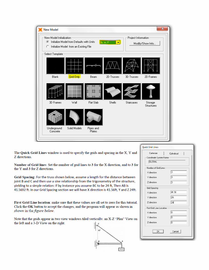

Switch to XZ Plan

Step 4 Assign Load
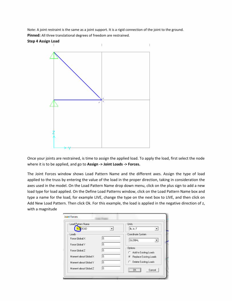
Note: A joint restraint is the same as a joint support. It is a rigid connection of the joint to the ground.
Pinned: All three translational degrees of freedom are restrained.
Step 4 Assign Load
Once your joints are restrained, is time to assign the applied load. To apply the load, first select the node
where it is to be applied, and go to Assign -> Joint Loads -> Forces.
The Joint Forces window shows Load Pattern Name and the different axes. Assign the type of load
applied to the truss by entering the value of the load in the proper direction, taking in consideration the
axes used in the model. On the Load Pattern Name drop down menu, click on the plus sign to add a new
load type for load applied. On the Define Load Patterns window, click on the Load Pattern Name box and
type a name for the load, for example LIVE, change the type on the next box to LIVE, and then click on
Add New Load Pattern. Then click Ok. For this example, the load is applied in the negative direction of z,
with a magnitude

The force then will be displayed in the node where it is applied for verification purposes. If more than
one force is applied to the structure, then the model will be refreshed and only display the most recent
force applied, so the previous applied forces will still be there, but just not visible.
1
2
3

Note: Linear Static analysis of a structure involves the solution of the system of linear equations.
Modal analysis if we want to study of the dynamic properties of structures under vibrational
excitation.

Now click on the Run Now button. SAP2000 will prompt different results of the analysis
according to what is requested. Reactions, member forces, moments, deformations and member
displacements are available for display.
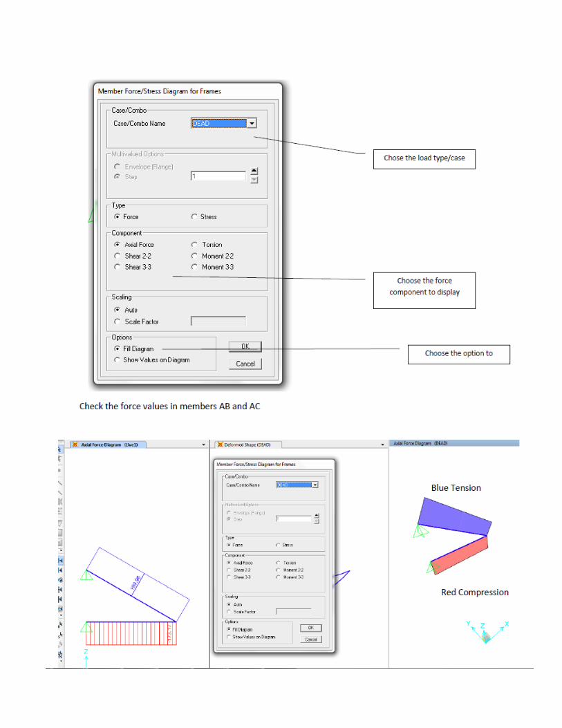
Step 6 Show Forces/Stresses - Frames/Cables/Tendons
Use the Display menu > Show Forces/Stresses > Frames/Cables/Tendons command to display
column, beam, brace, cable, or tendon forces directly on the SAP2000 model.
1. Click the Display menu > Show Forces/Stress > Frames/Cables/Tendons command to display
the Member Force Diagram for Frames form. Use the form to specify the parameters for the
display. (See Figure)
Case/Combo Name drop-down list. Choose the Load Case or Combination to be
displayed.
Multivalued Options. The type of load case/combination determines the option(s)
available:
For multi-mode cases, choose the mode number for which results are to be shown.
For multi-step cases, choose the step number, time step, or frequency step; choose
Envelope to view the maximum and/or minimum results over all steps.
Component options. Specify which component of force is to be displayed. Only one
component can be displayed at a time.
Scaling options. Select the Auto option to have SAP2000 automatically determine a
scaling factor. Select the Scale Factor option to specify a scale factor.
Fill diagram, Show Values on Diagram and Show Deformed Shape check boxes. Use
these options to display the force diagrams filled with no text values, unfilled with no text
values, unfilled with text values and on a deformed shape.
To display force diagrams filled with no text values, check the Fill Diagram check box.
Note that if the Show Values on Diagram check box is checked, uncheck it first before
checking the Fill Diagram check box.
To display force diagrams unfilled with text values, check the Show Values on Diagram
check box. Note that if the Fill Diagram check box is checked, uncheck it first before
checking the Show Values on Diagram check box.
To display force diagrams unfilled with no text values, uncheck both the Fill Diagram
and Show Values on Diagram check boxes.
Check the Show Deformed Shape check box to show the model as a deformed shape.
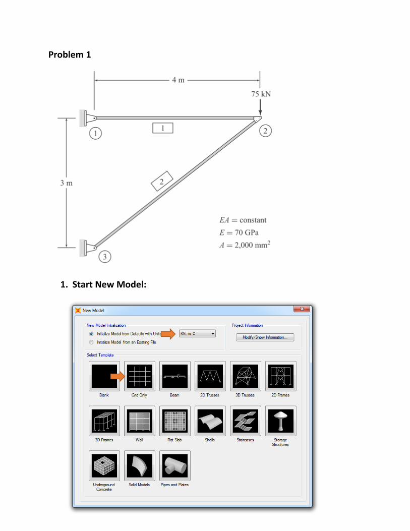
Problem 1
1. Start New Model:

2. Click Grid Only
3. Switch to XZ plan
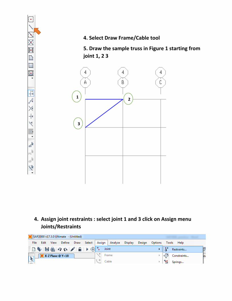
4. Assign joint restraints : select joint 1 and 3 click on Assign menu
Joints/Restraints
4. Select Draw Frame/Cable tool
5. Draw the sample truss in Figure 1 starting from
joint 1, 2 3
1 2
3
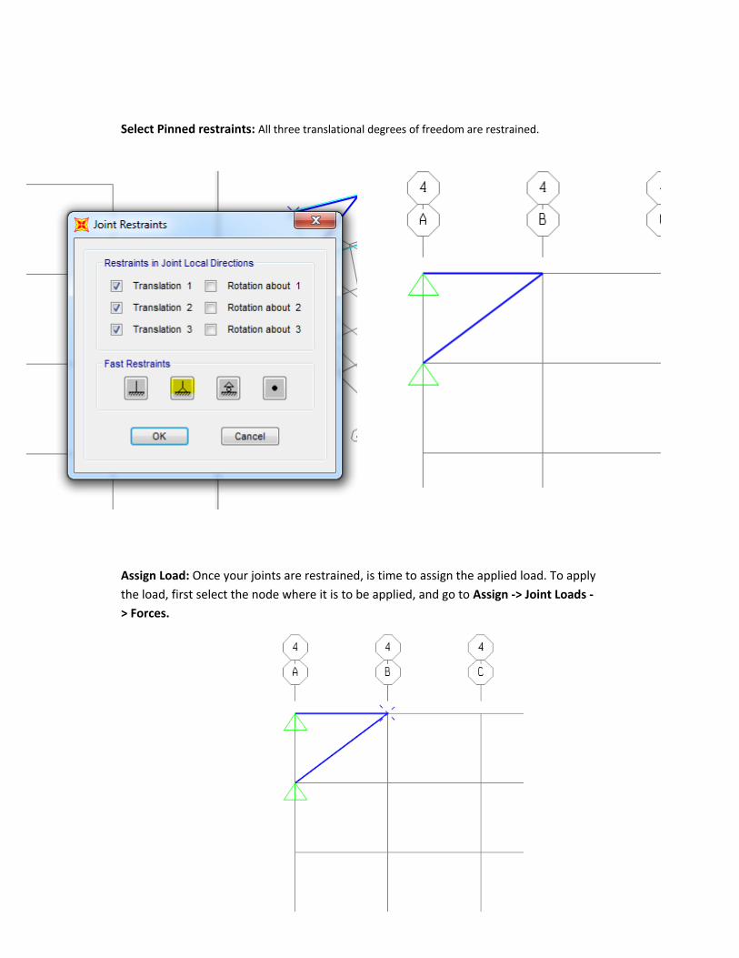
Select Pinned restraints: All three translational degrees of freedom are restrained.
Assign Load: Once your joints are restrained, is time to assign the applied load. To apply
the load, first select the node where it is to be applied, and go to Assign -> Joint Loads -
> Forces.

The Joint Forces window shows Load Pattern Name and the different axes. Assign the type of load
applied to the truss by entering the value of the load in the proper direction, taking in consideration the
axes used in the model. On the Load Pattern Name drop down menu, click on the plus sign to add a new
load type for load applied. On the Define Load Patterns window, click on the Load Pattern Name box and
type a name for the load, for example LIVE, change the type on the next box to LIVE, and then click on
Add New Load Pattern. Then click Ok. For this example, the load is applied in the negative direction of z,
with a magnitude

Click Ok the force then will be displayed in the node where it is applied for verification purposes.
Release Moments
Select all members-> Assign-> Frame-> Release/Partial fixidity -> select moment 22 and moment 33->ok
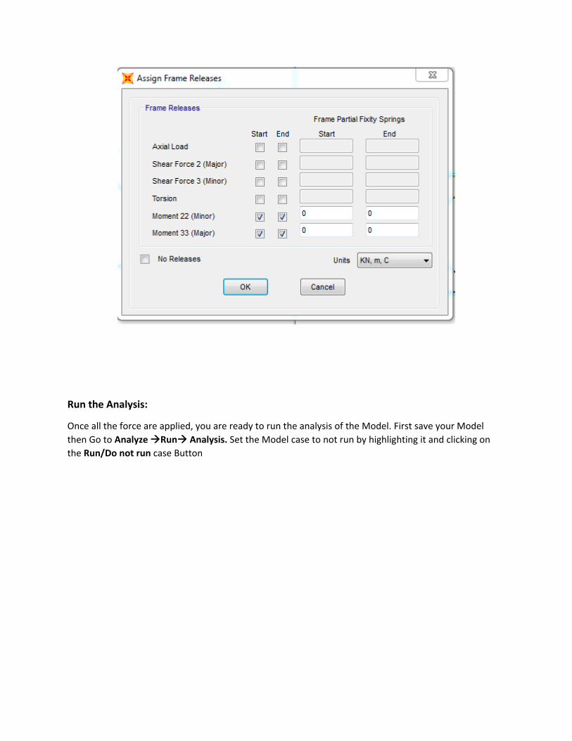
Run the Analysis:
Once all the force are applied, you are ready to run the analysis of the Model. First save your Model
then Go to Analyze Run Analysis. Set the Model case to not run by highlighting it and clicking on
the Run/Do not run case Button

After running the Model You will see a deformed shape of your structure

Show Forces/Stresses - Frames/Cables/Tendons
Click the Display menu > Show Forces/Stress > Frames/Cables/Tendons
command to display the Member Force Diagram. Make sure that axial force and
show values on diagram are selected. Click OK
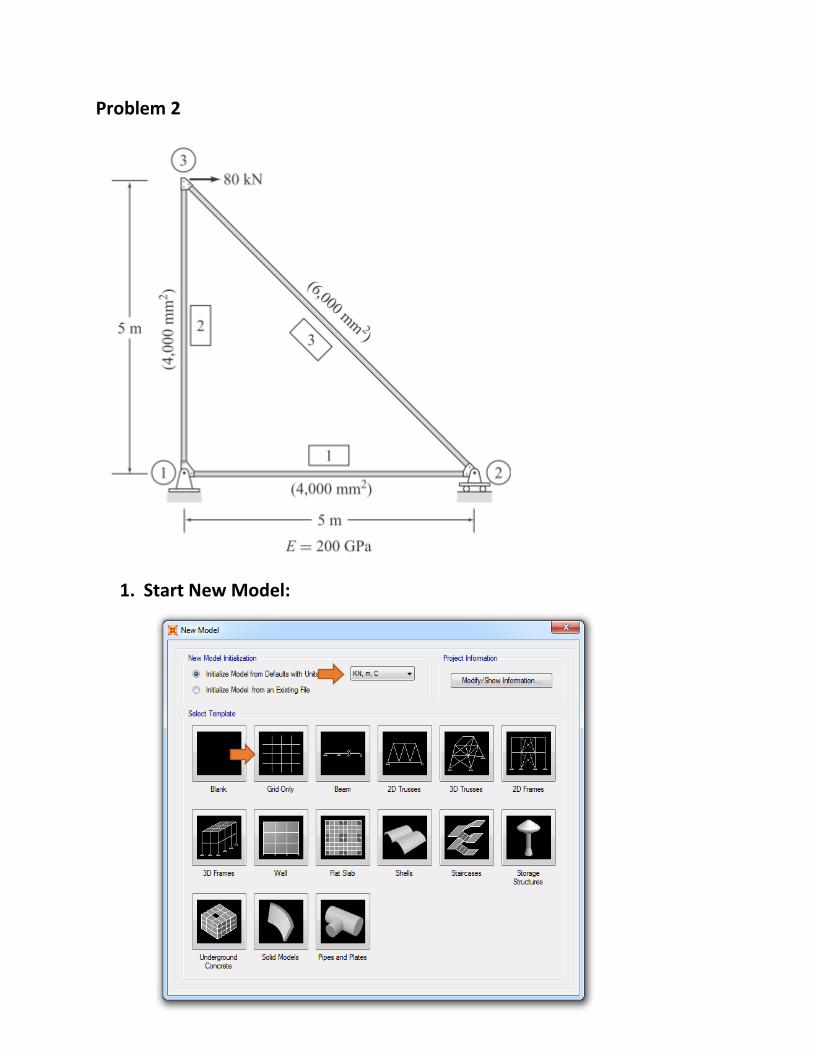
Problem 2
1. Start New Model:

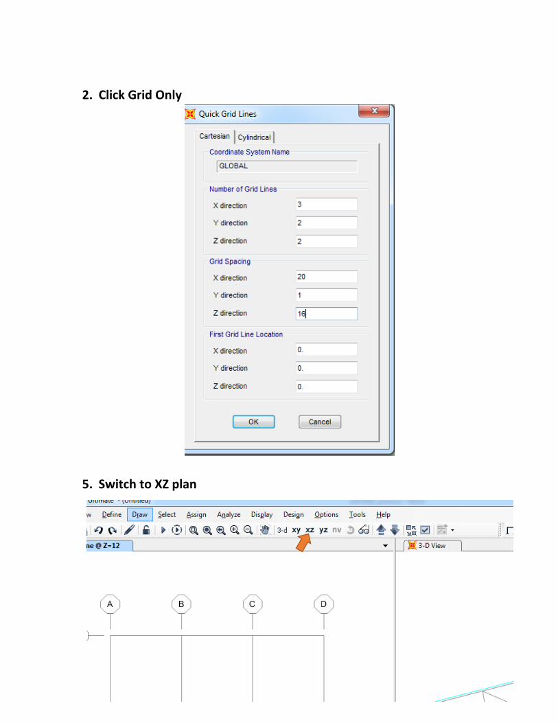
2. Click Grid Only
3. Switch to XZ plan
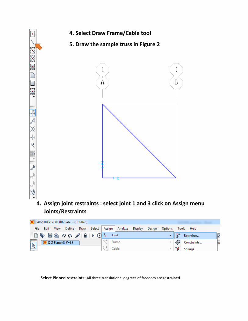
4. Select Draw Frame/Cable tool
5. Draw the sample truss in Figure 2
4. Assign joint restraints : select joint 1 and 3 click on Assign menu
Joints/Restraints
Select Pinned restraints: All three translational degrees of freedom are restrained.


The Joint Forces window shows Load Pattern Name and the different axes. Assign the type of load
applied to the truss by entering the value of the load in the proper direction, taking in consideration the
axes used in the model. On the Load Pattern Name drop down menu, click on the plus sign to add a new
load type for load applied. On the Define Load Patterns window, click on the Load Pattern Name box and
type a name for the load, for example LIVE, change the type on the next box to LIVE, and then click on
Add New Load Pattern. Then click Ok. For this example, the load is applied in the negative direction of z,
with a magnitude
Assign Load: Once your joints are restrained, is time to assign the applied load. To apply
the load, first select the node where it is to be applied, and go to Assign -> Joint Loads -
> Forces.

Release Moments
Select all members-> Assign-> Frame-> Release/Partial fixidity -> select moment 22 and moment 33->ok
Run the Analysis:
Once all the force are applied, you are ready to run the analysis of the Model. First save your Model
then Go to Analyze Run Analysis. Set the Model case to not run by highlighting it and clicking on
the Run/Do not run case Button

After running the Model You will see a deformed shape of your structure

Problem 3
1. Start New Model:
2. Click Grid Only
5. Switch to XZ plan

4. Select Draw Frame/Cable tool
5. Draw the sample truss in Figure 3

6. Assign joint restraints : select joint click on Assign menu
Joints/Restraints
Select Pinned restraints: All three translational degrees of freedom are restrained.
ROTATE THE SUPPORTS TO WORK ACCONDINTLY WITH THE MODEL
Select the supports -> Assign -> Joint-> Local Axis -> change the Y value to 90.

Assign Load: Once your joints are restrained, is time to assign the applied load. To apply
the load, first select the node where it is to be applied, and go to Assign -> Joint Loads -
> Forces.
The Joint Forces window shows Load Pattern Name and the different axes. Assign the type of load
applied to the truss by entering the value of the load in the proper direction, taking in consideration the
axes used in the model. On the Load Pattern Name drop down menu, click on the plus sign to add a new

load type for load applied. On the Define Load Patterns window, click on the Load Pattern Name box and
type a name for the load, for example LIVE, change the type on the next box to LIVE, and then click on
Add New Load Pattern. Then click Ok. For this example, the load is applied in the negative direction of z,
with a magnitude
Click Ok the force then will be displayed in the node where it is applied for verification purposes.

RELEASE MOMENTS
Select all members-> Assign-> Frame-> Release/Partial fixidity -> select moment 22 and moment 33-
>ok
Run the Analysis:

Once all the force are applied, you are ready to run the analysis of the Model. First save your Model
then Go to Analyze Run Analysis. Set the Model case to not run by highlighting it and clicking on
the Run/Do not run case Button
After running the Model You will see a deformed shape of your structure


Problem 4 :


![[TECH]Analyzing Trusses With Sap2000](https://img.pdfslide.net/doc/110x75/553d233b55034636568b4b3c/techanalyzing-trusses-with-sap2000.jpg)