Embed Size (px)
Citation preview
804 J. Opt. Soc. Am. A/Vol. 10, No. 5/May 1993
Analysis of two- and three-dimensional rigid and nonrigidmotions in the stereokinetic effect
Dejan TodoroviM
University of Belgrade, Serbia, Yugoslavia
Received October 16, 1991; accepted September 14, 1992; revised manuscript received November 4, 1992
Continued viewing of a rotating ellipse induces three types of percept: the veridical percept (rigid, flat, rotatingellipse), the amoeboid percept (nonrigid, flat, deforming ellipse), and the stereokinetic percept (rigid circulardisk rolling in three-dimensional space). A mathematical analysis of the nonveridical percepts is presented,based on the aperture problem and the assumption that the vector field N (the normal component of the rota-tional velocity field R of the ellipse) is the effective stimulus. Perceived nonrigidity of the amoeboid perceptis assessed by an analysis of the geometrical nonrigidity of N. Two analytical tests of geometrical rigidity ofvelocity fields are described. The first is based on the decomposition of the velocity gradient matrix, and thesecond is based on an analysis of the temporal derivative of the curvature of moving plane curves. Both testsconfirm the geometrical nonrigidity of N, on which the perceived nonrigidity might be based. A limitation ofboth approaches with respect to the analysis of shape-preserving nonrigidity is noted. For an understanding ofthe stereokinetic percept and its relation to N, a detailed kinematic analysis is presented of the type of motionthat a real circular disk (the physical stereokinetic disk) would have to perform in order to duplicate the per-ceived motion of the perceptual stereokinetic disk induced by the rotating ellipse. The analysis is based on theEulerian decomposition of rigid-body rotation into precession, nutation, and spin. It is concluded that thestereokinetic effect cannot be directly based on N because the projected velocity field of the physical stereo-kinetic disk, P differs from N. However, a subsequent transformation with N as the input vector field pro-duces an output vector field whose structure is similar to P, except for scale. This transformation is based onthe vector interaction algorithm, which is motivated by psychophysical data on contextual effects in the percep-tion of motion direction. It is also demonstrated that this algorithm predicts qualitative aspects of perceptsin several other relevant examples, such as the barber pole effect, translating nonoccluded line segments, andeccentrically rotating circles. An additional analysis shows that, although there is an infinity of figures pro-jectively equivalent to a static ellipse, the added dynamical constraint of projective equivalence of the velocityvector field of a moving figure to P implies that the only rigid figure consistent with stimulation and process-ing conditions is a circular disk. The bases of the three types of percept induced by the rotating ellipse areassumed to be the neural counterparts of three vector fields: R N, and P.
1. STEREOKINETIC EFFECT
The stereokinetic effect is a visual phenomenon in whichrotation of certain two-dimensional figures induces non-veridical percepts of objects moving in two-dimensional(2-D) and three-dimensional (3-D) space. It was discov-ered in the 1920's independently by the French artistDuchamp (see Ref. 1) and by the Italian psychologistsBenussi and Musatti2 and was rediscovered in the 1960'sby the American Duncan.3 The effect was demonstratedin a large variety of figures.4 "8 In this paper I will dis-cuss only a form of the effect induced by a simple stereo-kinetic stimulus, first studied by Benussi and by hisstudent, Musatti.2 In this version the stimulus is a rotat-ing ellipse. In a number of experiments this stimulus hasbeen presented in a variety of conditions: as a homoge-neously colored figure, as an outlined contour (consistingof one or several nested figures), or as a subjective con-tour; black on white, white on black, or luminous in dark-ness; with various degrees of ellipticity (ratio of minor tomajor axis varying between 0.38 and 0.94); at a range ofrotation speeds [between 5 and 50 cycles/min (cpm)]; withthe rotation axis lying in the center of the ellipse or posi-tioned eccentrically; under dim or normal lighting condi-tions; viewed monocularly or binocularly; and with therotation plane being frontoparallel or oblique with respectto the viewer. 4-6,8,19-24
The reports agree that continued viewing of a rotatingellipse generally elicits three types of percept, which willbe called veridical, amoeboid, and stereokinetic. In thebeginning the percept is veridical: the subjects describethe stimulus as a flat, rigid rotating ellipse. This phasemay be as brief as a few seconds, especially with experi-enced viewers, or may last up to a minute, with viewersnew to the phenomenon. In the second phase the perceptis still described as flat, but the figure is seen as nonrigid,plastic, or fluid. Nearly circular ellipses are perceivedto pulsate, less circular ellipses deform and rotate, butnarrow ellipses rotate rigidly. This percept was calledamoebalike by Wallach et al.8 The third type of perceptis the stereokinetic percept. In this phase the percept be-comes rigid again, but it consists of a slanted circular diskthat moves in 3-D space. The motion of the disk is de-scribed as wobbling or rolling on its edge. Although themotion of the perceived object is simple and perceptuallycompelling, it is not easily captured in words. One of thepurposes of the present paper is to describe this perceptmore precisely by the establishment of equations for itsmotion. In addition to the three percepts noted above,there are also reports of other 3-D percepts moving non-rigidly and of perspective reversals2 3 as well as, after pro-longed viewing (5-7 min), of a percept of a solid bodydescribed as an elongated egg'9 or a cigar.23
The stereokinetic effect has some aesthetic qualities,
0740-3232/93/050804-23$05.00 3 1993 Optical Society of America
Dejan Todorovi6
Vol. 10, No. 5/May 1993/J. Opt. Soc. Am. A 805
noted by all its codiscoverers. For example, Benussi25 hasdescribed the perceived body as "moving with astoundinggrace, smoothness, elasticity, and ease, rhythmically andadroitly" (my translation). Duncan's works based on theeffect are exhibited in the Phoenix Art Museum and inthe San Francisco Exploratorium. Duchamp used theeffect in two series of works, Anemic Cinema (1925)and Rotoreliefs (1935). Some of these objects were usedin the protrayal of dream sequences in the surrealist1940's movie Dreams That Money Can Buy by Richter.Note that Duchamp's label Rotorelief, which means a3-D effect (relief) through rotation, expresses an ideasimilar to Benussi's "stereokinetic," meaning soliditythrough motion.
The perceptual effects induced by the rotating ellipsepose a number of theoretical questions: How does thesame stimulus induce several qualitatively differentpercepts? Why does a rigid stimulus induce a nonrigidpercept? The motion in depth of the stereokinetic diskpresents a challenge for theories of such phenomena. Thestimulus contains no monocular depth cues. Stereoscopiccues are also ruled out, since the percept is enhanced bymonocular viewing. There are no intersecting lines ofchanging lengths and angles, unlike with the classicalkinetic depth effect.2 6 Nor does the stimulus contain iso-lated identifiable points, in contrast to the usual structure-from-motion demonstrations. In addition, the veridicalpercept is rather simple and is initially perceived as such.Why then does the visual system choose to introduce non-rigidities and 3-D effects?
This paper contains a mathematical analysis of the per-cepts induced by a rotating ellipse. Section 2 contains aformulation of the aperture problem, the decomposition ofthe velocity field into tangential and normal components,and its application to the rotating ellipse. Section 3 pre-sents an analysis of the amoeboid percept. In it two ana-lytical tests of geometrical rigidity are derived and appliedto the normal-component field of the rotating ellipse,which is proved to be nonrigid. This geometrical non-rigidity is assumed to underlie the perceived nonrigidityin the amoeboid percept. Section 4 presents an analysisof the stereokinetic percept. It contains a detailed geo-metrical and kinematic analysis of a real disk whose 3-Dmotion duplicates the stereokinetic percept. The 2-Dprojected motion field of this disk is compared with thenormal-component field of the rotating ellipse. The twofields are found to be different, implying that the normal-component field cannot directly underlie the stereokineticpercept. Section 5 introduces an algorithm, motivated bypsychophysical data on the perceived direction on motion,that models neural transformations of motion signals.When this algorithm is applied to the normal-componentfield of the ellipse, its output is a vector field that is as-sumed to underlie the stereokinetic percept. Section 6contains a brief summary of the results and a discussionof some unresolved issues.
2. APERTURE PROBLEM
It has been known for a long time that an important rolein the perception of the direction of motion of lines andcurves is played by the perpendicular orientation. For ex-ample, in 1911 Stumpf27 noted that a translating line or
edge, regardless of its physical direction of motion, is gen-erally perceived to move in the direction of the normal toits orientation. He applied this observation to the case ofthe rotating spiral and thereby explained its perceived ex-pansion/contraction. Wallach28 "9 investigated the per-cieved direction of motion of lines in a long series ofstudies. He stressed the optical ambiguity of the physicalmotion direction of lines and noted the tendency towardperceived motion in the perpendicular direction as one ofthe factors in motion perception. On the basis of suchresults, several authors have proposed a decomposition ofphysical motion into a visually effective and a visually in-effective component. For example, Musatti6 suggested "akinetic resolution of the objective movement for each pointof every line into two movements: one (visible) is perpen-dicular to the lines, and the other is along the direction ofthe lines themselves." Scott and Noland'0 claimed that"the only perceptible motion of a contour is that com-ponent which is normal to the contour." Metzger" hasoffered a similar analysis, based on Wertheimer."
More recently, the same type of analysis was proposed inthe form of a constraint for local motion detectors, underthe name of aperture problem.3 ' 7 Several computationalvision algorithms use the normal components as an inter-mediate stage in motion recovery.3-40 Thus there existsa considerable body of research that indicates the impor-tance of the normal component for motion perception.This research suggests that the effective stimulus causedby a rotating ellipse is not the true kinematic vector fieldof rotation but is the vector field of the normal componentof rotation. In order to analyze this field, I will present amathematical formulation of the aperture problem, basedon previous studies,39-42 using some basic notions from dif-ferential geometry.
A. General CaseThe aperture problem arises for curves in motion.sider a parametrically defined plane curve:
r(s) = {x(s),y(s)}.
Con-
(1)
In the following development the parameter s will often bedropped from the equations. Also, to increase clarity, Iwill employ both the vectorial and coordinate notations.
In an analysis of the aperture problem the notions ofunit tangent and normal vectors are useful. The unittangent vector of a curve r is defined by
|ril [(x')2 1
Ir'l [(X')' + (y,)2]1I2{ y}(2)
where the primes denote derivatives with respect to s.The unit normal vector is defined here by a 900 counter-clockwise turn of the unit tangent vector:
fi= k x= [(x')2 + ()2]/2{ YX},
where k is the unit vector of the positive z axis.Let a velocity vector field be defined on the curve:
V(s) = V(s),V,(s)1,
(3)
(4)
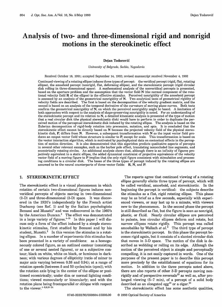
where the subscripts denote the Cartesian componentsof velocity. The velocity vector V can be decomposed(Fig. 1) into the tangential component T (the projection of
Dejan Todorovi6
806 J. Opt. Soc. Am. A/Vol. 10, No. 5/May 1993
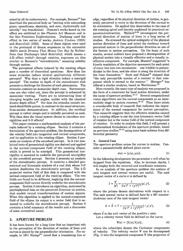
Such a velocity field, with p > 0 (counterclockwise rota-tion) and b = 0.67, is presented in Fig. 2(a).
When the motion of a curve r is rotation, then V inEqs. (5) and (6) is replaced by R, so that the tangentialand normal components of the velocity field are given by
N
Fig. 1. The aperture problem. The velocity vector V defined oncurve r is decomposed into the visually ineffective tangentialcomponent T in the direction of the unit tangent vector F and intothe visually effective normal component N in the direction of theunit normal vector h.
V onto t) and the normal component N (the projection of Vonto ):
VT * X' + VY y (T = (V * t Wt = 2(x')2 + (Y 2 X'y (5)
N = (V~~ = 14 (-y') + ,i..XN = (V *n)i = X T+(x)2 + (y')2 {-y x'}. (6)
There is an alternative formulation of T and N. In-stead of being formulated as projections onto the unit tan-gent and normal, they can be defined as transformationsof the velocity vector V:
T = AVc, N = AXVc, (7)
where the superscript C denotes column vectors and thetransformation matrices
F t.2 t ty]
y tX tY2 Jnx2 nxny
nynx n
-y'+ 'f AT p(k x r F)F =P (X,)2 + () 2 y
N = (r * tk X = X + V I-Y' 4}1(X')2 + (Y t)2
(12)
(13)
respectively. If the curve is the ellipse, then r in the aboveequations is replaced by e, and the two fields are given by
T= sin2 s ab {-sin s,b cos s},si + b 2 cos 2 s
a(1 - b2)cos s sin sP sin 2 + b2 cos 2
s {b cos s,sin s}.
(14)
(15)
These velocity fields are presented in Figs. 2(b) and 2(c).Note that R = T + N; that is, the vector field in Fig. 2(a)is the sum of the fields in Figs. 2(b) and 2(c). Velocityfields like the ones in Figs. 2(a) and 2(c) were presented byHildreth.3 9 These fields depict the ellipse in the canonicalposition. As the stimulus curve rotates, the vector fieldsrotate accordingly.
(8)
which contain the Cartesian components of t and n, per-form the appropriate rotation and scaling of the velocityvector V. The alternative formulation of N is equivalentto the one used by Reichardt et al.,4 2 with n playing therole of the unit gradient vector.
B. Rotating EllipseIn the version of the stereokinetic effect analyzed here,the curve is an ellipse and the motion is rotation aboutthe origin. Consider a parametrically defined ellipse,e(s) = {e.(s),e,(s)} in the canonical position, that is, theellipse lies in the xOy plane, its center is at the origin, andits major axis is aligned with the x axis:
e, = a cos s, ey = ba sin s,
(a)
(b)
(9)
where a is the major half-axis, b is the parameter of ellip-ticity, and 0 s < 2r.
The linear velocity of uniform rotation about the ori-gin, with angular velocity p, of a curve r = {x(s), y(s)} isgiven by
R = pk r = {-pypx}. (10)
The velocity field R(s) = {R(s), Ry(s)} of the rotating el-lipse is thus given by
Ry = pa cos s.
(c)Fig. 2. (a) Rotational velocity vector field R defined on an el-lipse with ellipticity b = 0.67. (b) Tangential component field Tof the rotational field R. (c) Normal-component field N of therotational velocity field.
T
t
V
Dejan Todorovi6
(11)R,, = -pba sin s,
Vol. 10, No. 5/May 1993/J. Opt. Soc. Am. A 807
The following analyses are based on the assumption thatthe aperture problem is wholly operative, that is, that thetangential component is visually completely ineffective. Itwill be examined whether and how the remaining normal-component field N can help one to understand the amoe-boid and stereokinetic percepts. In other words, can theperceived deformations and 3-D motions be explained ifthe effective visual stimulus is adequately represented byN instead of by the true kinematic field R?
Before these analyses are made, another issue must bebriefly addressed. A problem that will come up repeatedlybelow is the comparison of different vector fields. For ex-ample, a visual inspection of the vector fields depicted inFig. 2 indicates similarities and differences between thesefields. It would be useful to express such qualitative judg-ments by quantitative indicators. Such an indicator canbe based on an average of a difference measure of pairs ofcorresponding vectors of two vector fields; by correspond-ing vectors, I mean vectors that are associated with thesame point on the curve in two vector fields. There areseveral scalar difference measures of a pair of vectors, aand b, and it is not clear which is the most appropriate forthe present purpose. Such measures include the magni-tude of the difference vector la - b, the difference of themagnitudes of the vectors, lal - ibl, and the angular dif-ference of the vectors, Z(a,b) = [cos-'(ab)1/lal lbl. Ashortcoming of the first two measures is that they dependon the absolute magnitudes of the vectors. A shortcomingof the angular difference is that it is undefined for zerovectors, such as the ones at the poles of the ellipse in N.One can overcome the latter shortcoming by ignoring suchcases. Although it is not perfect, the angular differencemeasure is intuitively clear and will be adopted here.
The indicator of the difference betwen two vector fieldswill be referred to as the mean absolute angular differ-ence. It is calculated as the average of the angular differ-ences of corresponding vectors (if both are nonzero), wherethe sense of the difference (clockwise or counterclockwise)is disregarded. For two sampled vector fields Ui and Vion a curve, each containing n vectors, the mean absoluteangular difference is defined by
M =1- arccos (16)
Here are some examples of this indicator: the mean ab-solute angular difference is 14.50 between vector fields Rand T, 73.50 between R and N, and of course 90° betweenT and N. The first two values do not add up to the thirdbecause of the four excluded measures at the poles. Thesenumbers corroborate the intuitive judgment that fields Rand T are mutually similar but different from N.
3. AMOEBOID PERCEPT
A few seconds after it begins to rotate, the ellipse usuallyloses its rigidity. Wallach and co-workers8 8 have attri-buted the perceived nonrigidity to a process of identityimposition. On the other hand, Musatti6 and Renvall4
have suggested that the nonrigid percept is due to thevisual effectiveness of the normal component of rotationvelocity. Hildreth 3 9 has proposed a related idea, which
will be discussed in Section 6. One possibility is thatidentity imposition may itself be due to the action of thenormal component.
Why should N, the normal-component field of rotationvelocity, induce nonrigid percepts? An inspection of thisfield [Fig. 2(c)] indeed suggests shape deformations, suchas a bulging out of the ellipse in the first and third quad-rants and a cave-in in the second and fourth quadrants.However, a problem with such intuitive assessments ofproperties of vector fields is that they may not be reliable.For example, a simple visual inspection of a velocity fieldof geometrically rigid motion, such as R, the rotation vec-tor field of the ellipse [Fig. 2(a)] does not necessarilyconvey the impression of a rigid transformation; on thecontrary, one might even wrongly conclude that this ve-locity field represents nonrigid motion, because in someregions (for example, in quadrants 1 and 3) the vectorsdiverge. The latter conclusion would be correct if thesevectors represented actual motion paths, because in thatcase the interpoint distances in those regions would in-crease; however, these vectors in fact represent instan-taneous velocities. Such examples show that a moreappropriate assessment of rigidity must include formaltests that answer the question of whether a given veloc-ity field, such as N, represents geometrically rigid or non-rigid motion.
It should be noted that the question of rigidity of Nis somewhat different from the rigidity issues that arepursued in many structure-from-motion studies (e.g.,Refs. 43-45). Usually the researcher controls the rigidityof the stimulus and wishes to establish whether the cor-responding percept is phenomenally rigid. For example,often the stimulus as a 3-D structure is rigid, its 2-D pro-jection is nonrigid, but the corresponding percept is rigid.Such stimuli are usually defined as sequences of struc-tured spatial configurations of isolated dots. The dotsare identifiable in the sense that in general each dot in aframe has a corresponding dot in the next frame that rep-resents the same physical particle in the next moment ofmotion. Thus the rigidity of the stimulus (as a 2-D or 3-Dstructure) can be examined in a direct procedure if oneestablishes whether the distances between dot pairs (in2-D or 3-D) change or do not change.
In the present problem the stimulus (the rotating ellipse)as a 2-D physical configuration is certainly rigid, and thecorresponding amoeboid percept is nonrigid. The issue athand is to establish whether the presumed effective stimu-lus, the normal-component field N, is geometrically rigid.Since N is defined as a velocity field and not as a discretedisplacement field, the above direct procedure is not appli-cable. Furthermore, as the above example with the rota-tional field of the ellipse shows, an approach in which thedisplacement field is approximated by the velocity fieldmay lead to incorrect rigidity assessments. As anotherexample of the inadequacy of the velocity field as an ap-proximation of the displacement field for rigidity assess-ments, consider a circle rotating about its center: in thiscase all the velocity vectors are tangent to the contourand point outward with respect to the contour. If suchvectors represented actual motion paths, then even forsmall displacements the circle would expand. Such mo-tion is nonrigid, whereas the real motion of the circle is ofcourse rigid.
Dejan Todorovi6
808 J. Opt. Soc. Am. A/Vol. 10, No. 5/May 1993
Such examples indicate that, for the analysis of rigidityof velocity fields such as N, alternative procedures mustbe used. In Subsections 3.A and 3.B I will describe twoanalytical tests of geometrical rigidity and apply them tothe normal-component field N. The tests confirm that Ncannot be a velocity field of 2-D rigid motion. However,it will be pointed out that geometrical nonrigidity is notequivalent to shape deformation.
A. First Rigidity Test: Decomposition of the VelocityGradient MatrixRigid motion is a special case of general motion, whichalso includes nonrigid deformations and flows. Generalmotion is studied in continuum mechanics.46 Conceptsfrom this field can be applied in the analysis of visualmotion.47
-49 The linear structure of a 2-D velocity field
V = {VxVJ} is analyzed by decomposition of its velocitygradient matrix:
ax ay
avy av* (17)
ax ay
One type of analysis of F is the decomposition into a sumof four constant matrices that are weighted by variablecoefficients,4 9 the so-called differential invariants. It isstraightforward to show that
r , CM, (18)l -I
where
Cl = Cdiv = axax
02 curl = aVyax
aVx
C4 = Cdef2 y
a VY M = Md [1 j (19)
y M 2 = Mcur = 1]' (20)
- ay M3 = Mdefi = Lo -i X' (21)
ay M M 0 1ax M4 d ef, L oJ (22)
motion (Vdef, and Vdef 2):
V1 = Vdiv = a{xy}, C = Cdiv = 2a,
C2 = C3 = C4 = 0, (24)
(25)
(26)
(27)
two or more coefficientsFor all other types of motion,must be nonzero.
The necessary and sufficient analytical conditions thata 2-D vector field must fulfill in order to represent theinstantaneous velocity field of rigid motion are
WV. av WV aVy=-- - = - = 0 (28)ay ax ax ay
From these conditions it follows that, for rigid motion,Cdiv = Cdefi = Cdef2 = 0; the only nonzero coefficient canbe Ccurl. The presence of any of the other three coef-ficients indicates nonrigid motion. Thus the test of non-rigidity of a velocity field reduces to an examination of themagnitudes of these four coefficients.
Before this test can be applied to the normal-componentfield N, a technical difficulty must be solved. If one is tocalculate the derivatives of a field V with respect to x andy, the field must be of the form V(x, y). However, N is ofthe form N(s); that is, it is a function of a single parame-ter. N is defined not on a plane or on some 2-D subset ofthe plane but on a 1-D manifold. One solution to thisproblem is to extend the definition of N in an appropriatemanner. For example, consider a set of concentric ellipsesthat fill the whole plane. This can be achieved if the terma in Eqs. (9) of the ellipse is regarded not as a constant butas a parameter that varies from zero to infinity. Everypoint on the plane now lies on an ellipse and is associatedwith a rotation velocity vector and with the correspondingnormal-component vector with respect to the ellipse. Thenormal-component field N now takes the form
The two shear matrices Mdcfi and Md~f2 can be combinedinto a single matrix, which one can transform to yield asingle shear coefficient and a shearing axis.47
Different types of 2-D motion and their velocity fieldsare characterized by different sets of coefficients. Thesimplest case is translation, which has a constant velocityfield, so that all four coefficients are zero. Somewhat lesssimple are four types of elementary motion, defined below,for which only one coefficient Ci is nonzero, while thethree others are zero.49 Their velocity fields are
V = aMirc, i = 1, 2,3,4, (23)
where a is a constant that defines the rate of motion andr = {x, y}. These elementary motions are isotropic dila-tation (VdiV), rotation (Vcurl), and two types of shearing
(1 - b2 )b2x 2yN = p b4
X2 + y2
N, = (1 - b2)xy 2
-=P b4x2 + y'
(29)
(30)
so that the appropriate derivatives with respect to x and ycan be calculated. There is a psychophysical justificationof this mathematical procedure: if, instead of a singleellipse, a nested set of ellipses is rotated, the perceptualeffects are qualitatively unchanged and may even be moresalient.
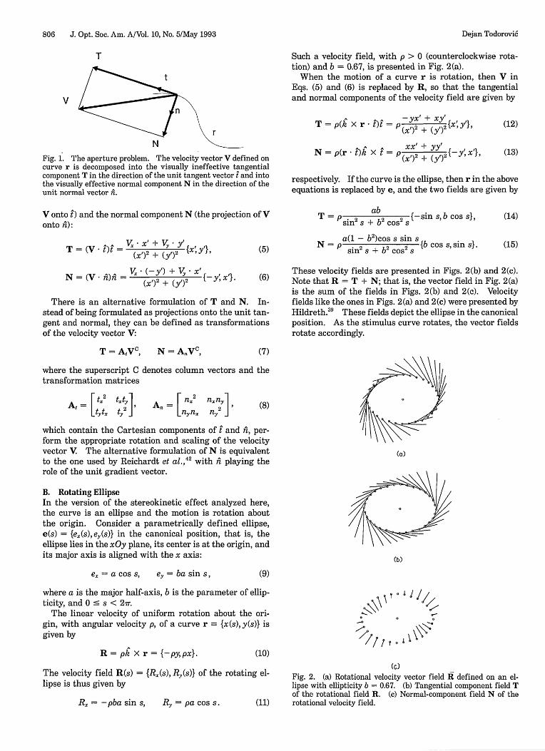
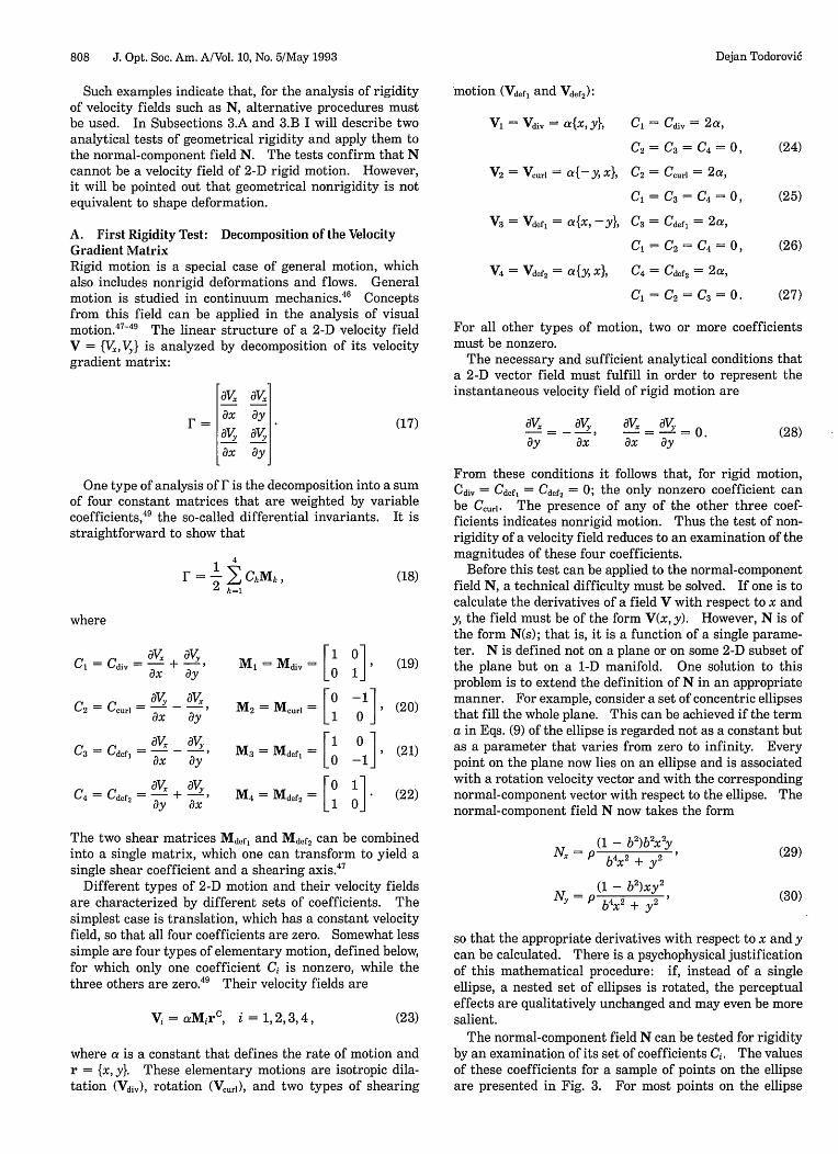
The normal-component field N can be tested for rigidityby an examination of its set of coefficients Ci. The valuesof these coefficients for a sample of points on the ellipseare presented in Fig. 3. For most points on the ellipse
V2 = Vcuri = a{-y,x}, 2 = Ccuri = 2 a,
Cl = C3 = C4 = 0,
V3 = Vdefl = a{x, -y}, C3 = Cdef = 2 a,
C1 = C2 = C4 = 0,
V4 = Vdef2 = a{y, x}, C4 = Cdef2 = 2a,
Cl = C2 = C3 = 0.
Dejan Todorovi6
Z
Vol. 10, No. 5/May 1993/J. Opt. Soc. Am. A 809
UU
00
00
. U 0a 0
03E3. .
000C] 0 0
00 00 0
* 0U
U
_D
(a)
0
0
00 00 00.
130 0
000 0
00
00
(c)
0
0
0* 0a 0
M UI
0
00
(b) (d)
Fig. 3. Sampled coefficients of the velocity gradient matrixof the normal-component field N. In this figure and in Fig. 4,absolute numerical values are coded by box area, and the sign iscoded by color: white is positive, and black is negative. (a) Cdiv,
(b) Ccurl, (c) Cdef,, (d) Cdef2.
all four coefficients are nonzero. Thus the normal-component field represents geometrically nonrigid mo-tion. The graphical representation also gives some insightinto the structure of nonrigidity. For example, note howthe values of Cdiv correspond to "bulging out" and "cavingin," as noted above.
B. Second Rigidity Test: Temporal Derivative ofCurvatureAs Subsection 3.A showed, the method of velocity grad-ient matrix decomposition is suitable primarily for ve-locity fields defined on 2-D manifolds. For velocityfields defined on 1-D manifolds one must extend to twodimensions in order to apply the method, but the ap-propriate extension might not always be as easy to con-struct as in the case of the rotating ellipse. Thus, in thecase of curves, another approach to rigidity may be moreappropriate. I will now present such an alternative pro-cedure, based on the concept of the temporal derivative ofcurvature.
Curvature is the main local feature of a plane curve. Itis usually defined as a scalar K. I will also define here acurvature vector K, whose magnitude is K and whosedirection vector is k, the unit vector of the positive direc-tion of the z axis. The introduction of a curvature vectoris a mere technicality, the only purpose of which is to sim-lify the following equations. For a plane curve r(s), whichneed not be arc parameterized, the curvature vector is de-fined as
r' X r" x'y" -y'"K = ir'l3 = [(X')2 + (y')] 3 /2 (31)
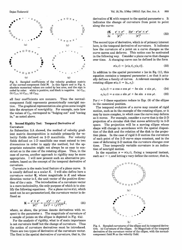
where, as above, the primes denote derivatives with re-spect to the parameter s. The magnitude of curvature ofa sample of points on the ellipse is depicted in Fig. 4(a).
For the analysis of rigidity, what is of main importanceis not curvature itself but the change of curvature. Thusthe notion of curvature derivatives must be introduced.There are two types of derivative of the curvature vector.The first is the spatial derivative of curvature, that is, the
derivative of K with respect to the spatial parameter s. Itindicates the change of curvature from point to pointalong the curve:
aK r' X r"' 3(r' r")r' r (32)as Ir' I 3 ir 15
The second type of derivative, which is of primary interesthere, is the temporal derivative of curvature. It indicateshow the curvature of a point on a curve changes as thecurve moves and deforms. This notion can be motivated
*M in the following way. Consider a plane curve that changesM. over time. A changing curve can be defined in the form
r(s, t) = {x(s, t), y(s, t)}. (33)
In addition to the spatial parameter s [as in Eq. (1)], thisequation contains a temporal parameter t, so that it actu-ally defines a family of curves. A relevant example is therotating ellipse e(s, t) = {e,, e}:
e.(s, t) = a cos s cos pt - ba sin s sin pt, (34)
e,(s, t) = a cos s sin pt + ba sin s cos pt. (35)
For t = 0 these equations reduce to Eqs. (9) of the ellipsein the canonical position.
The temporal evolution of a curve may consist of rigidmotion, such as in the example of the rotating ellipse, or itmay by more complex, in which case the curve may deformas it moves. For example, consider a curve that is the 2-Dprojection of a circular disk that moves arbitrarily in 3-Dspace. The projection will be a moving ellipse whoseshape will change in accordance with the spatial disposi-tion of the disk and the relation of the disk to the projec-tion plane. In the case of rigid 2-D motion the curvatureof each point of the 2-D curve stays constant, and in thecase of deforming 2-D motion the curvature changes overtime. Thus temporally variable curvature is an indica-tion of nonrigid motion.
In the equation r = r(s, t), fixing a temporal instant,such as t = T, and letting s vary define the contour, that is,
00n01E1
FILILI
00
0C3
U
0
0 0 0 0 0
0 0 0 0 0
0EMCo
F1oLILILI1
n E
(a)
. To . . .U ~~~0
00C08
0
(b)
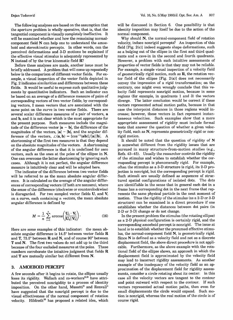
Fig. 4. Sampled curvatures of the ellipse and its temporal deriva-tive. (a) Curvature of the ellipse. (b) Magnitude of the temporalderivative of the curvature vector of the ellipse, with the normal-component field N as the velocity field.
U0
MMa
Dejan Todorovi6
To 0
810 J. Opt. Soc. Am. A/Vol. 10, No. 5/May 1993
the spatial disposition of all points of IConversely, fixing s = cr and letting t vthat is, the temporal disposition of acurve over time. Note that a fixed valitity on points on the curve, meaning thsuffers strong deformations over timmakes sense to refer to the same pointsequently, it also makes sense to ask hithat point changes over time. In otidefine the temporal derivative of curvecurve r = r(s, t) as the derivative withporal parameter t:
aKat
ar' dr"at X r" + r' X atat at
Irl I
3(r' -
One can simplify this equation by notiof a point on the curve is defined, as usiderivative of position:
V ar(s, t)at
If velocity is a continuous function ofare also continuous, then the spatial aitives can be interchanged, and the tencurvature is given by
aK V' x r" + r' V" 3(r' *at ir
3
The motivation for the introduction ctemporal derivative of curvature was t(test. Therefore it must be verifiedvanishes for rigid motion. Rigid mostant be decomposed into a translateNow, if V = constant is the velocity fthen V' = V" = 0, so that the wholeEq. (38) is zero. On the other hand,field of rotation, then
V= pk X r, V' = pk X r'
the curve at time r. field N are both defined for the canonical position, that is,ary define the path, for t = 0. Thus the test can be directly applied. The ap-single point of the plication of the test shows that the motion of the ellipseLie of s confers iden- induced by N is nonrigid everywhere except on the poles.at, even if the curve The magnitude of the temporal derivative of curvature one, it still generally a sample of ellipse points is depicted in Fig. 4(b). Thisof the curve. Con- figure shows that curvature is increasing in the first and:Ow the curvature at third quadrants and decreasing in the second and fourth;ier words, one can quadrants, in accord with the intuitive assessments ofiture for points of a bulging out and cave-in of the normal-component field.respect to the tem- As the ellipse rotates, the normal-component field rotates
with it. At each instant of rotation the action of the nor-mal component of rotation velocity would induce an in-
ar' X r" crease of curvature in two diagonally opposed quarters ofAt (36) the curve and a decrease of curvature in the other twor PI 5 quarters. Thus it becomes understandable why the cor-
responding percept should consist of a rotating deform-ng that the velocity ing ellipse.Lial, by the temporal In sum, both the analysis of the velocity gradient matrix
and the analysis of the temporal derivative of curvatureconfirm that the normal-component field of the rotating
(37) ellipse is geometrically nonrigid and thus could serve as abasis of a nonrigid percept. These tests corroborate theidea that the nonrigid amoeboid percept is caused by the
time and r' and r" fact that the effective stimulus is not R, the rigid rota-ad temporal deriva- tional velocity field of the ellipse, but the nonrigid normal-aporal derivative of component velocity field N, which arises because the
tangential component T is filtered from R through the ac-V')r' ,, r"tion of the aperture effect. The analyses also describe the
I)rx r (38) structure of the nonrigidity of N. In order to assess therI5 appropriateness of these analyses, one would need to com-
f the notion of the pare the geometrical nonrigidity structures with psycho-physical nonrigidity judgments of the amoeboid percept.
; use it as a rigiaitythat this quantityLion can at any in-ion and a rotation.'ield of translation,right-hand side ofif V is the velocity
V" = P r (39)
from which it follows that
r' X V" = -V' X r", r' V'= .
so that again the whole right-hand side of Eq. (38) is zero.Thus, for both translation and rotation, K does not changeover time. In conclusion, since rigid motion of a planecurve keeps K constant, temporally variable K implies non-rigid motion. The magnitude of the temporal derivativeof curvature is thus a measure of rigidity.
How can this test be applied to N? For a given instantin time, say t = 0, Eq. (38) defines the instantaneous tem-poral derivative of curvature. To calculate it, one needsto have defined first the instantaneous spatial dispositionof the curve, given by r(s, 0), and second the instantaneousvelocity field defined on the curve, given by V(s, 0). In thecase of present interest the curve is the ellipse, and thevector field over the curve is not the kinematic velocityfield R but its normal component N, the presumed effec-tive velocity field. The ellipse and the normal-component
C. Shape-Preserving NonrigidityThe global notion of shape cannot be straightforwardlyreduced to the local concept of curvature. Therefore testsof rigidity are not automatically tests of shape change.For example, consider a circle that increases in size. Ifthe increase is isotropic, then the figure keeps its circularshape. However, the rigidity tests indicate that such mo-tion is nonrigid. This can be easily seen if one notes thatthe curvature of a circle with radius R is equal to 1/R, sothat the curvature decreases when the circle increases.Thus this is an example of shape-preserving nonrigid mo-tion. Another class of examples of shape-preserving non-rigidity is provided by curves that move along themselves(so to speak): in such motion the velocity vectors arepurely tangential to the curve and have a zero normal com-ponent. Such motions do not change the shape of a curvebut are in general nonrigid, except for cases such as linestranslating in the direction of their tangent, circles rotat-ing about their center, and helices in helicoidal motion.
A relevant example is motion of points along an ellipse.Three such fields are presented in the left-hand column ofFig. 7 below. These fields arise in the analysis of thestereokinetic percept and are defined in Section 4. Thisclass of motion can be called elliption (in analogy to rota-tion) because each moving point always stays on the ellipse.One can see that such motion is nonrigid by consideringtwo points at the opposite poles of the major axis, which,after a quarter-turn along the ellipse, are located at theopposite poles of the minor axis. Thus the distance be
Dejan Todorovi6
Vol. 10, No. 5/May 1993/J. Opt. Soc. Am. A 811
tween them has changed, which is the mark of nonrigidity.Nonrigidity of elliption is also formally verified by bothanalytical tests. Interestingly, the temporal derivative ofcurvature of this motion is at all points equal to the spatialderivative of curvature, which makes sense because pointsmove along the ellipse. However, despite being nonrigidand curvature changing, this motion is shape preservingbecause during elliption the ellipse does not change itsshape (or even its location). The moral is that a positiveoutcome of nonrigidity tests does not necessarily mean de-formation of shape.
4. STEREOKINETIC PERCEPT
The second nonveridical percept induced by the rotatingellipse is a rigid slanted circular disk that rolls in a pecu-liar manner. How does such a percept arise, and what isits relation to the normal-component field? In this sec-tion I will attempt to answer these questions by first es-tablishing equations for the shape, the disposition, and the3-D motion of the perceived body and then comparing theprojected 2-D velocity field of the body with the normal-component field of the rotating ellipse.
A plausible starting assumption for the explanation ofall stereokinetic effects is that the rotating flat stimu-lus in some way induces perceptual conditions that areequivalent to the situation in which a physical body movesin a particular manner in 3-D space. However, a detailedanalysis along these lines, describing the characteristicsof the body and the way in which it moves, has rarely beenprovided. I will briefly discuss first the shape of the per-ceived body and then the manner of its motion.
With respect to perceived shape, there is unanimity inthe literature, since all the sources describe it as circular.Now, a given elliptical shape in the xOy plane can indeedresult from a projection of a circular disk appropriatelyslanted with respect to the projection plane. However,this shape is only one among an infinity of projectivelyequivalent shapes. Consider a vertical elliptical cylindererected upon the plane ellipse. Curves generated by theintersection of any spatial surface and the cylinder willproject orthographically into the ellipse in the xOy plane.In particular, intersections of the cylinder and all planesoblique with respect to plane xOy are slanted ellipses pro-jecting into the plane ellipse. For certain positions andslants the intersecting ellipse is actually a circle. Amongall the geometrical possibilities the perceptual systemchooses that one, the circle, as the stereokinetic percept.It should be emphasized that the moving stereokineticdisk is a vivid and compelling 3-D perceptual experience,quite different from the intellectual exercise of observinga static plane ellipse and imagining slanted circles and el-lipses projecting into it. It will be shown below that thecircle is the only rigid figure compatible with the dynami-cal stimulus conditions.
With respect to perceived motion of the stereokineticdisk, there is less unanimity, although it appears that allagree that it is some kind of rolling. One problem is thatwe have a poor descriptive vocabulary for talking aboutdifferent kinds of motion. Therefore, in what follows,some notions from classical kinematics will be used, withthe assumption that the perceived motion is a physicallyrealizable behavior of a rigid body. The problem will be
approached in the following way. Consider a subject con-fronted with two stimuli. One stimulus is a flat rotatingellipse, defined by its half-axis a, ellipticity b, and angularspeed of rotation p. The rigid percept induced by the ro-tating ellipse will be called the perceptual stereokineticdisk. The other stimulus is a real circular disk, which,through some mechanical device, can be moved in any de-sired manner. The problem to be solved is to define, if itis possible, the dimensions and the motion of the real disksuch that it completely duplicates the shape and the motionof the given perceptual stereokinetic disk induced by therotating ellipse. In the following discussion such a realdisk will be called the physical stereokinetic disk or simplythe disk. It is assumed that the physical stereokineticdisk is a well-textured body, so that it escapes the apertureproblem. A detailed description of the motion of such adisk will, by definition, also be a detailed description ofthe somewhat elusive motion of the stereokinetic percept.This description will be provided in the following sub-sections. Once the characteristics of the motion of thephysical stereokinetic disk are specified, its projected 2-Dvelocity field can be compared with the normal-componentfield N. In this way the relevance of N for the explanationof the stereokinetic effect can be assessed. It will be con-cluded that N cannot provide the whole explanation of thestereokinetic percept.
A. Geometry of the Physical Stereokinetic DiskThe basic condition that the physical stereokinetic diskmust fulfill in order to mimic the shape and the motionof the perceptual stereokinetic disk is that its projectedcontour at all times coincide with the contour of the rotat-ing stimulus ellipse. Orthographic projection will be as-sumed throughout. The problem is to find the size andthe spatial disposition of a circular disk that projects intothe given ellipse. Let us start with the static case of theellipse in the canonical position [Eqs. (9)]. The appropri-ate inclination of the disk can be found as follows. Startwith a circular disk with radius a lying in the xOy planecentered at the origin 0 of a 3-D rectangular coordinatesystem. One of its diameters, D., belongs to the x axis,and a second one, Dy, belongs to the y axis. Imagine thatthe disk is rotated counterclockwise about the x axis. Di-ameter D, does not move during this motion, and diameterDy rotates in the yOz plane about the origin. The angle ofrotation 0 is the angle between plane xOy and the plane ofthe disk and is equal to the angle between the two posi-tions of diameter Dy. When 0 is increased from zero, theprojected shape of the circle onto plane xOy is trans-formed from a circle into increasingly thinner ellipses un-til it degenerates to a line segment for 0 = 900, when thecircle lies in the xOz plane; this process is reversed for 0increasing from 90° to 1800. The major axis of the pro-jected ellipse is equal to diameter D., and the minor axis isthe projection of diameter Dy. In order for the projectedshape of the disk to match the canonical ellipse, one mustdefine the angle of rotation by the equation cos 01 = b.Two such angles exist, 0 and 0' = 1800 - 0. The positionin which the angle of rotation is 0 < 900 will be called thecanonical position of the disk. This geometrical ambigu-ity is probably reflected in the fact that the perceptualstereokinetic disk is sometimes seen to flip in orientation,especially with lower rotation speeds (5-15 cpm).23
Dejan Todorovi6
812 J. Opt. Soc. Am. A/Vol. 10, No. 5/May 1993
B. Kinematics of the Physical Stereokinetic DiskWhat are the possible motions of the physical stereokineticdisk? Any motion can be instantaneously decomposedinto a translation and a rotation. A translation parallelto the direction of the z axis makes no difference in ortho-graphic projection, nor does the perceptual stereokineticdisk move in such a manner. A translation in any otherdirection is ruled out because it would move the projectedcenter of the disk away from the origin of the xOy plane,whereas the center of the stimulus ellipse is stationary.For the same reason, rotation of the disk about an axisthat does not pass through the origin is also ruled out.What is left is only rotation about an axis through theorigin, which may change its orientation in time. Thespecification of the motion of the stereokinetic disk re-duces to the specification of the equation of the axial rota-tion vector w, whose direction is collinear with therotation axis and whose magnitude is equal to the angularvelocity of rotation.
Since the axis of rotation of the disk always passesthrough the center of the disk, it follows that the center isstationary. Motion of a body with one fixed point 0 iscalled spherical motion because, no matter how the bodymoves, each point P must remain on a sphere whose centeris the fixed point 0 and whose radius is the distance ofpoint P from point 0. Spherical motion has three degreesof freedom, which one can specify in different ways. Oneway is to use the three Cartesian coordinates wx, w, andw, of the axial rotation vector w. This is equivalent to adecomposition of w into three vectors: w = w.{1,0,0},wy = wy{0, 1, 0} and w, = w,{0, 0, 1}, which represent rota-tions about the three coordinate axes. These vectors arecollinear with the coordinate axes and thus have constantdirection, but they may have temporally variable magni-tudes. Another way to analyze the rotation vector, usefulin projection problems, is to decompose it into two vectors:a component parallel to a projection plane and a compo-nent perpendicular to it. There is still another approach,standard in rigid-body kinematics and well suited to thepresent problem. In this approach, in addition to thefixed-coordinate system, a mobile-coordinate system,rigidly connected to the moving body, is introduced. Thespatial relations of the axes of the two coordinate sys-tems are expressed by means of three temporally variableEulerian angles of precession, nutation, and proper rota-tion (or spin). The axial rotation vector w is decomposedinto three corresponding component axial vectors thatrepresent the axes and the angular velocities of preces-sion, nutation, and spin. The precession axis coincideswith the z axis. The axes of nutation and of spin have, inthe general case, temporally variable orientation, so thatthe corresponding vectors can vary both in direction andin magnitude.
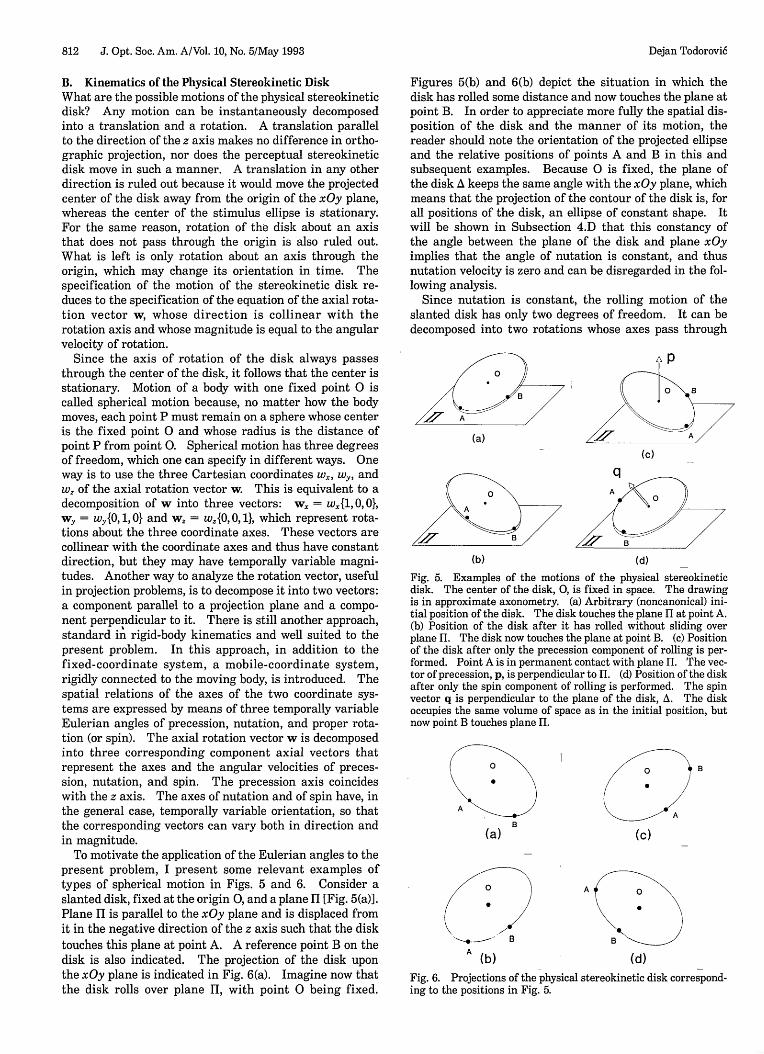
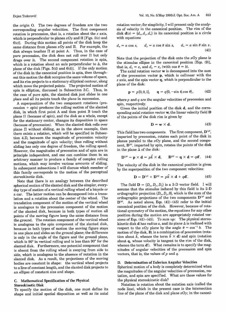
To motivate the application of the Eulerian angles to thepresent problem, I present some relevant examples oftypes of spherical motion in Figs. 5 and 6. Consider aslanted disk, fixed at the origin 0, and a plane II [Fig. 5(a)].Plane II is parallel to the xOy plane and is displaced fromit in the negative direction of the z axis such that the disktouches this plane at point A. A reference point B on thedisk is also indicated. The projection of the disk uponthe xOy plane is indicated in Fig. 6(a). Imagine now thatthe disk rolls over plane I, with point 0 being fixed.
Figures 5(b) and 6(b) depict the situation in which thedisk has rolled some distance and now touches the plane atpoint B. In order to appreciate more fully the spatial dis-position of the disk and the manner of its motion, thereader should note the orientation of the projected ellipseand the relative positions of points A and B in this andsubsequent examples. Because 0 is fixed, the plane ofthe disk A keeps the same angle with the xOy plane, whichmeans that the projection of the contour of the disk is, forall positions of the disk, an ellipse of constant shape. Itwill be shown in Subsection 4.D that this constancy ofthe angle between the plane of the disk and plane xOyimplies that the angle of nutation is constant, and thusnutation velocity is zero and can be disregarded in the fol-lowing analysis.
Since nutation is constant, the rolling motion of theslanted disk has only two degrees of freedom. It can bedecomposed into two rotations whose axes pass through
(a)
(c)
q
A0
B
(d)
Fig. 5. Examples of the motions of the physical stereokineticdisk. The center of the disk, 0, is fixed in space. The drawingis in approximate axonometry. (a) Arbitrary (noncanonical) ini-tial position of the disk. The disk touches the plane H at point A.(b) Position of the disk after it has rolled without sliding overplane H. The disk now touches the plane at point B. (c) Positionof the disk after only the precession component of rolling is per-formed. Point A is in permanent contact with plane H. The vec-tor of precession, p, is perpendicular to H. (d) Position of the diskafter only the spin component of rolling is performed. The spinvector q is perpendicular to the plane of the disk, A. The diskoccupies the same volume of space as in the initial position, butnow point B touches plane H.
B
(a)B
(c)
(b) (d)
Fig. 6. Projections of the physical stereokinetic disk correspond-ing to the positions in Fig. 5.
(b)
Dejan Todorovi6
Vol. 10, No. 5/May 1993/J. Opt. Soc. Am. A 813
the origin 0. The two degrees of freedom are the twocorresponding angular velocities. The first componentrotation is precession, that is, a rotation about the z axis,which is perpendicular to planes xOy and II [Figs. 5(c) and6(c)]. During this motion all points of the disk keep thesame distance from planes xOy and II. For example, thedisk always touches II at point A. Thus, in the case ofpure precession, the disk does not roll over II but onlydrags over it. The second component rotation is spin,which is a rotation about an axis perpendicular to A, theplane of the disk [Figs. 5(d) and 6(d)]. If the only motionof the disk in the canonical position is spin, then through-out this motion the disk occupies the same volume of space,and its rim projects to a stationary elliptical contour, alongwhich move the projected points. The projected motion ofspin is elliption, discussed in Subsection 3.C. Thus, inthe case of pure spin, the slanted disk just slides in oneplace and all its points touch the plane in succession.
A superposition of the two component rotations (pre-cession + spin) produces the rolling motion of the slanteddisk, in which first point A and then point B touch theplane II (because of spin), and the disk as a whole, exceptfor the stationary center, changes its disposition in space(because of precession). When the slanted disk rolls overplane II without sliding, as in the above example, thenthere exists a relation, which will be specified in Subsec-tion 4.D, between the magnitude of precession velocityand the magnitude of spin velocity; thus rolling withoutsliding has only one degree of freedom, the rolling speed.However, the magnitudes of precession and of spin are inprinciple independent, and one can combine them in anarbitrary manner to produce a family of complex rollingmotions, which may involve various amounts of sliding.In subsequent subsections I will discuss which member ofthis family corresponds to the motion of the perceptualstereokinetic disk.
Note that there is an analogy between the describedspherical motion of the slanted disk and the simpler, every-day type of motion of a vertical rolling wheel of a bicycle ora car. The latter motion can be decomposed into a trans-lation and a rotation about the center of the wheel. Thetranslation component of the motion of the vertical wheelis analogous to the precession component of the motionof the slanted disk, because in both types of motion allpoints of the moving figure keep the same distance fromthe ground. The rotation component of the vertical wheelis analogous to the spin component of the slanted disk,because in both types of motion the moving figure staysin one place and slides on the ground plane; the differenceis only in the angle of the figure and the ground plane,which is 900 in vertical rolling and is less than 900 for theslanted disk. Furthermore, one potential component thatis absent from the rolling wheel is swaying from side toside, which is analogous to the absence of nutation in theslanted disk. As a result, the projections of the movingbodies are constant in shape: the vertical wheel projectsto a line of constant length, and the slanted disk projects toan ellipse of constant size and shape.
C. Mathematical Specification of the PhysicalStereokinetic DiskTo specify the motion of the disk, one must define itsshape and initial spatial disposition as well as its axial
rotation vector; for simplicity, I will present only the analy-sis of velocity in the canonical position. The rim of thedisk d(s) = {d.,, d, d,} in its canonical position is a circlewith equations
d = a cos s, d, = a cos 0 sin s, d, = a sin 0 sin s.(41)
Note that the projection of the disk onto the xOy plane isthe stimulus ellipse in the canonical position [Eqs. (9)],that is, d. = e. and dy = ey (with cos 0 = b).
The axial rotation vector w is decomposed into the sumof the precession vector p, which is collinear with thez axis, and the spin vector q, which is perpendicular to theplane of the disk:
p = p{0,0,1}, q = q{0, -sin 0,cos 0}, (42)
where p and q are the angular velocities of precession andspin, respectively.
Given the initial position of the disk d, and the corre-sponding axial rotation vector w, the linear velocity field Dof the points of the disk rim is given by
D =w x d. (43)
This field has two components. The first component, D(P),imparted by precession, rotates each point of the disk inplanes parallel to the xOy plane, and the second compo-nent, D(q), imparted by spin, rotates the points of the diskin the plane A of the disk:
DP) = p X d = pk d, D) = q X d = qd'. (44)
The velocity of the disk in the canonical position is givenby the superposition of the two component velocities:
D = D(P) + D(q) = pk X d + qd'. (45)
The field D = {D, Dy, D,} is a 3-D vector field. I willassume that the stimulus induced by this field is its 2-Dorthographic projection {D., Dy, 0}, which is the sum of theorthographic projections of the two components D(P) andW). As noted above, Eqs. (41)-(45) refer to the initialcanonical position of the disk. However, because of rota-tional symmetry of the motion, the equations for any otherposition during the motion are appropriately rotated ver-sions of Eqs. (41)-(45). To sum up: The physical stereo-kinetic disk d has radius a, and its plane A is inclined withrespect to the xOy plane by the angle 0 = cos' b. Themotion of the disk, D, is a combination of precession (rota-tion about k, whence the term k x d) and spin (rotationabout q, whose velocity is tangent to the rim of the disk,whence the term d'). What remains is to specify the mag-nitudes of angular velocities of the precession and spinvectors, that is, the values of p and q.
D. Determination of Eulerian Angular VelocitiesSpherical motion of a body is completely determined whenthe magnitudes of the angular velocities of precession, nu-tation, and spin are specified. What are these values forthe physical stereokinetic disk?
Nutation is rotation about the nutation axis (called thenode line), which in the present case is the intersectionline of the plane of the disk and plane xOy; in the canoni-
Dejan Todorovi6
814 J. Opt. Soc. Am. A/Vol. 10, No. 5/May 1993
cal position, the node line is the x axis. Rotation of thedisk about this axis changes the angle between plane Aand plane xOy, which changes the size of the minor axis ofthe projected ellipse and thus the shape of the projectedcontour of the disk. However, the shape of the stimulusellipse stays constant during rotation. This propertymeans that the initial angle of nutation, which defines thedegree of slant of the disk with respect to the projectionplane, must stay constant during the motion of the disk.Therefore the angular velocity of nutation of the physicalstereokinetic disk must be zero.
Precession of the disk causes a rotation of its projectionabout the origin. If this projection is to coincide at alltimes with the stimulus ellipse, the precession velocity pof the physical stereokinetic disk must be equal to the ro-tation velocity p of the stimulus ellipse. Thus the preces-sion component DIP' is given by
D(P) = pk X d. (46)
The orthographic projection of the precession componentis given by
ID., Dy" = pa{-b sin ,cos s}, (47)
which is identical to R, the rotation velocity field of the
ellipse [Eqs. (11); Fig. 2(a)].The preceding specifications of nutation and precession
are relatively straightforward. However, the determina-tion of the remaining degree of freedom, the angular ve-locity q of spin, is a more difficult problem. Because of
the mutual independence of precession, nutation, and spin,a real disk can have any value of spin, regardless of the two
other velocities. The problem at hand is to find that valueof spin that is in accord with the stereokinetic percept. Iwill consider several possibilities.
The first possibility is that there is no spin, that is,q = 0. This value corresponds to the example of pure pre-
cession in Figs. 5(c) and 6(c). However, this choice of q is
in conflict with the percept: all published accounts of themotion of the perceptual stereokinetic disk (as well as my
own observations using turntables and computer screens)involve some rolling and not a simple dragging in which all
the points keep the same relative depths. Thus, if the de-scriptions of the percept are to be trusted, some amount ofspin must be involved, that is, q must take a nonzero value.
The second possibility is that the motion of the physicalstereokinetic disk is a rolling over a surface without slid-ing. In this case, q = -p cos 0 = -pb, which is a kine-matically natural value of spin and is relatively easilyrealizable physically. However, I will argue that this valueis not a perceptually appropriate choice of q because it im-plies a type of motion of the disk that is supported neitherby observational data nor by kinematic arguments.
Consider the disk in any initial position, for example theone in Fig. 5(a), and imagine that it performs a full roll,meaning that it returns to the initial position. In thecourse of this motion its projected contour, the ellipse, willmake a full 360 rotation in the xOy plane. Now, it is thecase that the disk, as a body, occupies the same volume of
space in the initial and final positions of this motion; how-ever, it is not the case that the individual points of thedisk occupy the same absolute spatial locations in the ini-tial and final positions of the disk. In fact, no point ofthe disk (except the stationary center at the origin) willend up, in the final position of the disk, in the same loca-
tion as the initial position of the disk. For example, ifpoint A of the disk touches the plane II in the initial posi-tion, this point will not touch the plane after the full rollwithout sliding. I will express this fact by saying that thetwo positions of the disk are volume equivalent but notpoint-for-point equivalent. The reason for this nonequiva-lence is the following. Consider first the simpler situ-ation, in which the vertical disk of radius a rolls over a
plane. Let the disk in its initial position touch the planeat point A (which belongs to the disk and not to the plane)
and then roll without sliding until it again touches theplane at point A. The locus of points in the plane in whichthe disk has touched it is a line whose length is equal to the
circumference of the disk, 27ra. Now, consider the case of
the slanted disk with the same radius, which initiallytouches the plane at point A. Because the disk is fixed atthe center, the locus of points in which it touches the planeduring the roll is a circle with radius a cos 0. The circum-ference of this circle is 2a cos 0, which is smaller than
the circumference of the disk. Thus, when the disk rollswithout sliding and arrives in the final position, it willstill not touch the plane at point A; in order for it to do so,it would need to roll an additional length of 2ra( - cos 0),for only then would its total path length be equal to thecircumference 2va. The consequence of this argument isthat the initial and final positions of the slanted disk thatrolls without sliding are not point-for-point equivalent. Agood observer watching the motion of the disk should beable to detect this nonequivalence. One way to help the
observer make this judgment would be to mark a point Aat the rim of the disk as a visual anchor. In this way theobserver would be able to note that point A does not touch
the plane after the full roll of the disk.The preceding analysis is concerned with a physical
body, the slanted disk that rolls without sliding. Does theperceptual stereokinetic disk roll without sliding? Is it oris it not point-for-point equivalent after a full roll? Un-fortunately, there are no experimental data on this issue.According to my own observations, it is difficult to makesuch judgments with any degree of certainty because theperceived figure has no salient features that can be usedas anchors. In an attempt to resolve this issue, one ormore locations were marked on the contour of a stimulusellipse by small circles that were rotating with the ellipse.Informal observations of such stimuli indicate that the ap-pearance of the stereokinetic percept is delayed in com-parison with the case of the plain rotating ellipse. Whenthe percept does appear, the circular marks perceptuallydetach themselves from their physically fixed locations atthe rim of the rolling stereokinetic disk and slide indepen-dently along the contour. After a 360 turn of the stimu-lus ellipse, the circular marks return of course to theirinitial physical locations, but because they have phenome-nally moved with respect to the perceptual stereokineticdisk, they are of no help in resolving the above questions.
Although the perceptual data on the amount of spin areinconclusive, a simple kinematic analysis indicates thatthe stimulus conditions provide no basis for the percept tobe in any way different in the final position (or after anyother 360° turn) from that in the initial position. Thestimulus ellipse is, after a 360° turn, point-for-point iden-tical to its initial position. The vector fields R and N arealso identical in the two positions. It is hard to see why
the percept of the disk should be different, that is, not
Dejan Todorovi6
Vol. 10, No. 5/May 1993/J. Opt. Soc. Am. A 815
point-for-point equivalent, when the stimulus contour andthe velocity field are the same for the two positions. Insum, the choice of q = -pb would need additional dataor arguments.
If the previous two values of q are rejected, that is, ifthe circle does roll but does not roll without sliding, thenit must slide while it rolls. The problem is to determinethe amount of sliding. Among all possible values of spinvelocity there is one that involves the correct amount ofsliding that makes the physical stereokinetic disk not onlyvolume equivalent but also point-for-point equivalent in theinitial and final positions. This value is q = -p = -p.In this case, during the time the disk makes a full-cycleprecession, it also makes a full-cycle spin, so that eachpoint returns to its initial location. This choice of qmakes the motion of the disk fully compatible with thestimulus conditions, in that both the disk and the ellipseare point-for-point equivalent after a full turn. The ve-locity of the disk in this case is
D = p(k X d - d'). (48)
Note that the senses of the two motions are opposite; thatis, if precession is counterclockwise, then spin is clockwiseand vice versa.
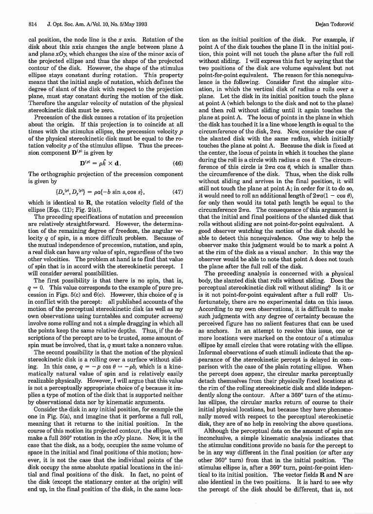
Figure 7 should facilitate an understanding of the roleof spin velocity. The left-hand column presents the 2-Dvelocity field S, which is the orthographic projection of thespin component D(q) of D. The three fields [Figs. 7(a),7(b), and 7(c)] correspond to three different values of q, tobe defined below. The right-hand column [Figs. 7(d), 7(e),and 7(f)] presents the corresponding 2-D field P, which isthe orthographic projection of D, the velocity field of thephysical stereokinetic disk. The field P is the sum ofthe projection of the precession component DIP' (whichwas shown to be identical to the rotation velocity R ofthe ellipse) and the projection S of the spin componentDq). Thus
P=R+ S. (49)
The first of the discussed values, q = 0, is not presentedin Fig. 7, because in that case S = 0 and P = R, and thisfield is depicted in Fig. 2(a). In the presented examples,the summation of a nonzero field S and of R produces P.Figures 7(a) and 7(d) correspond to the second of the dis-cussed values, q = -pb, that is, rolling without sliding.Figures 7(b) and 7(e) correspond to the value q = -p, thethird of the discussed possibilities. Figures 7(c) and 7(f)correspond to the value q = -p/b. Note that in Fig. 7(d)all vectors of P are parallel to one axis of the ellipse, and inFig. 7(f) they are all parallel to the other axis. For valuesof q between the values q = -pb and q = -p/b the shapesof the vector fields assume some intermediate structures,with a particularly symmetric form for q = -p in Fig. 7(e).
What is the value of q that corresponds to the stereo-kinetic percept? In the absence of relevant psychophysicaldata no definite conclusion can be reached. The preced-ing analysis has indicated that some amount of spin mustbe involved. The physically natural choice of rolling with-out sliding has no experimental confirmation and is inconflict with the stimulus conditions. Note that theprevalence of rolling without sliding in the physical worldis a consequence of the laws of friction; it is not necessaryto assume that equivalent laws govern the domain of per-
ceptual illusions. Among the discussed values, the valueq = -p is singled out because it is not in conflict withwhat is known about the percept (in contrast to the valueq = 0) and because it is in accord with the kinematicanalysis (since it ensures point-for-point equivalence).Furthermore, it is unclear how the choice of additionalvalues of q could be theoretically justified. Based on thepreceding arguments, I will tentatively conclude that -pis the appropriate value of q and that Eq. (48) is thesought-for equation of motion of the physical stereokineticdisk. In this case, S, the projection of the spin componentDq, is given by
S = ID.(q) D,(q)} = pa{sin s, -b cos s}. (50)
The field P in this case is presented in Fig. 7(d) and isgiven by
P = {D.,DJ} = pa(1 - b){sin s,cos s}. (51)
In Eq. (51) the first goal of this section has been reached.If the preceding analysis is accepted, the 2-D field P is theprojected velocity field of the physical stereokinetic diskthat fully duplicates the motion of the perceptual stereo-kinetic disk.
E. Relation of N and PIt is now possible to assess the role of the normal-componentfield N in the stereokinetic percept. In the preceding sub-sections two different stimuli were specified that inducethe percept of a slanted rolling disk. The first stimulusis a flat rotating ellipse whose velocity field is R; the per-cept induced by this stimulus is the illusory perceptualstereokinetic disk. The second stimulus is the physicalstereokinetic disk whose projected 2-D velocity field is P;
IT
(d)
(b) (e)
(c) (f)
Fig. 7. Examples of S (left-hand column) and P = R + S (right-hand column). (a), (d) q = -bp; (b), (e) q = - p; (c), (f) q = - p/b.
(a)
Dejan Todorovi6
11
I I I.
T II
6
G -
o
- - a A
816 J. Opt. Soc. Am. A/Vol. 10, No. 5/May 1993
although there exist no actual psychophysical data for thisstimulus, it can be assumed that the percept induced by itwould be veridical, especially if it is a well-textured body,so that the aperture problem does not come into operation.
The fact that two different stimuli induce equal perceptssuggests that at some relevant stage of visual processingthe two stimuli cause identical effects. This identity cer-tainly does not exist at the level of the projected velocityfields generated by the two stimuli, because R is clearlydifferent from P: the value of the mean absolute angulardifference (the indicator of the difference between two ve-locity fields introduced in Section 2) is 73.2° for these twofields. An interesting possibility, of special relevance inthe context of the present paper, is that identity is gener-ated when R is transformed into N as a consequence of theaperture problem. Now that both N and P are specified,it is possible to compare them.
A qualitative visual inspection of these two fields[Figs. 2(c) and 7(d)] indicates clear similarities, but it alsoindicates clear differences. Both fields point outward(with respect to the elliptical contour) in the first andthird quadrants and inward in the second and fourthquadrants. However, the vectors of N diverge in the firstand third quadrants and converge in the second and fourthquadrants, whereas for the vectors of P it is the other wayaround. In addition the vectors of N diminish and vanishtoward the poles of the ellipse, whereas the vectors of P allhave the same magnitude. The value of the mean abso-lute angular difference between these two fields is 39.4°.
For other values of q the size of the difference indicatorshows no appreciable decrease. For example, for q = -p/bthe value of the difference indicator is 37.8° and forq = -pb it is 53.3; the minimum value occurs for q =
-0.73p and is equal to 33.3°. One can reach additionalinsight into the relation among N, P, and q by solving,with p = p and q as unknown, the equations N = D. andN = D, [where D is defined by Eq. (45)]. The value of qthat satisfies these equations would make the projectedvelocity field of the physical stereokinetic disk identical toN. These equations can indeed be solved for q, and thecommon solution is
pb(52)sin s + b2 cos2
However, such a value is not admissible as an angularvelocity. By definition, the value of angular velocity isidentical for all points of a rigid body, whereas the solvedvalue depends on the spatial parameter s and is differentfor different points of the disk. A disk with such a spinvelocity would need simultaneously to spin faster in someregions and slower in others, an impossibility for a rigidbody. This analysis confirms that no value of q can makethe projected velocity field P of the physical stereokineticdisk identical to the normal-component field N. Further-more, in Subsection 5.E a more general result will beproved that shows that N cannot be the projected velocityfield of any rigid figure.
This result poses a serious challenge to the initial ideathat the structure of the normal-component field offersan explanation for the stereokinetic effect. I see threetypes of approach to this challenge: the initial idea canbe fully accepted, completely repudiated, or appropriatelymodified.
In the first approach, one possibility is that the normal-component field N is an adequate representation of thepercept, which implies, because of the solved value of q,that the percept is nonrigid. There are indeed descrip-tions of nonrigid versions of the perceptual stereokineticdisk.2 3 However, most accounts report only the rigidvariant. If the rigidity judgments of the subjects are tobe trusted, this possibility must be ruled out. Anotherpossibility is that the difference between P and N is smalland negligible, so that N is an acceptable approximation ofP and thus can serve as the basis for the rigid stereo-kinetic percept. A problem of this explanation is that thedifference indicator of these vector fields appears to berather large (39.4). There are no psychophysical data onhow small differences of this type need to be in order tobe negligible.
The second approach is to deny any relevance of thenormal-component field for the stereokinetic percept.One possible alternative explanation of the effect couldbe sought in some higher-level cognitive processes. Thecrucial aspect of the stimulus situation would be theprojective equivalence of the flat ellipse and the slantedcircle, and a process of perceptual simplicity or economymight be invoked to account for the percept. In thisway one could explain the shape of the perceived body be-cause it could be argued that a slanted circle is a simplerpercept than a projectively equivalent slanted ellipse.However, this approach would face the following prob-lems: Why should the illusory percept of a slanted rollingdisk be simpler than the veridical percept of a flat rotat-ing ellipse? Why should such an economy principle comeinto operation only when the stimulus moves and notwhen it is static? There also remains the problem of spinvelocity. The projective equivalence of the slanted circleand the rotating flat ellipse is ensured by the value of theinitial angle of nutation and the magnitude of precessionvelocity. The magnitude of spin velocity, whatever it is,cannot disturb the projective equivalence of the two con-tours because during this motion the projected points stayon the contour. The problem is, however, that thismathematical indeterminacy does not appear to be re-flected in a corresponding perceptual indeterminacy:the perceptual stereokinetic disk appears to have a defi-nite value of spin. Where does this value come from?One possibility is that it comes from our experience withrolling bodies. This idea would favor the percept ofrolling without sliding, because we often see such motion,although we sometimes also see rolling with sliding, as inwheels of cars driving over icy terrain. However, it is un-clear how the assumption of the influence of experience,debated by Benussi, 25 Renvall,4 and Musatti, 6 could be ap-propriately tested (that is, outside cultures that have notinvented the wheel).
Finally, the third approach is that the normal-componentfield N is only an intermediate step in the processing ofthe stimulus. This field could be subject to subsequenttransformations, which may result in a vector field thatis similar to or identical to P. The status of N as an inter-mediate step is strongly suggested by several examples ofHildreth3 9 that show that this field can significantly devi-ate from the perceived motion direction. This approachwill be examined in Section 5, where an algorithm for thetransformation of vector fields will be described.
Dejan Todorovi6
Dejan Todorovi6
5. VECTOR INTERACTION ALGORITHM
There are many algorithms that deal with various aspectsof motion perception. Most relevant in present contextare algorithms that involve two stages of motion process-ing.3 1
40 The first stage consists of an extraction of thenormal component of velocity, and the second consists of afurther transformation of the normal-component field. Iwill present here another two-stage model, whose secondstage is called the vector interaction algorithm. Themathematical development of the model will be presentedfirst, followed by the application of the algorithm to sev-eral stimuli. It will be shown that the algorithm appliedto the rotating ellipse indeed transforms N into a vectorfield similar to P, except for scale.
There are various, partially conflicting criteria that canbe applied in the construction of an algorithm for a per-ceptual task, such as motion detection. They includecomputational considerations, mathematical criteria,physical constraints, neural realism, veridical stimulusreconstruction, and relevant psychophysical data. Thefollowing algorithm is motivated by psychophysical dataon the effect of context in motion direction perception.They pertain to the fact that the direction of a local mo-tion signal is perceived differently in isolation than it iswhen signals with other directions are present in the vi-sual field. Some of these effects are assimilation phe-nomena: the direction of perceived local motion becomesmore similar to the contextual motion signal, or station-ary stimuli are perceived to move in the direction of thecontext.5 0 53 Others are contrast phenomena: perceiveddirection becomes more different from contextual direc-tion, or stationary stimuli are perceived to move in theopposite direction.54 -5 8 In a recent study these two typesof phenomenon were named homokinesis and hetero-kinesis.59 In that paper it was shown that homokinesis(assimilation) prevails for smaller distances and hetero-kinesis (contrast) predominates for larger distances.
The notions of contrast and assimilation are tradition-ally used in brightness perception. Since brightness is ascalar and motion is a vector, contrast and assimilationare somewhat more complex in the motion domain. Oneway in which these effects can be modeled is to evaluaterules of interaction of vectors that represent motion sig-nals. An algorithm that implements a simple vector in-teraction rule will be presented in Subsection 5.A. Thealgorithm will first be described for the degenerate case ofinteraction of only two motion signals; it will then be ex-tended to the case of a sample of points on a curve; andfinally I will briefly note how it can be generalized for thecase of a full 2-D field of motion vectors.
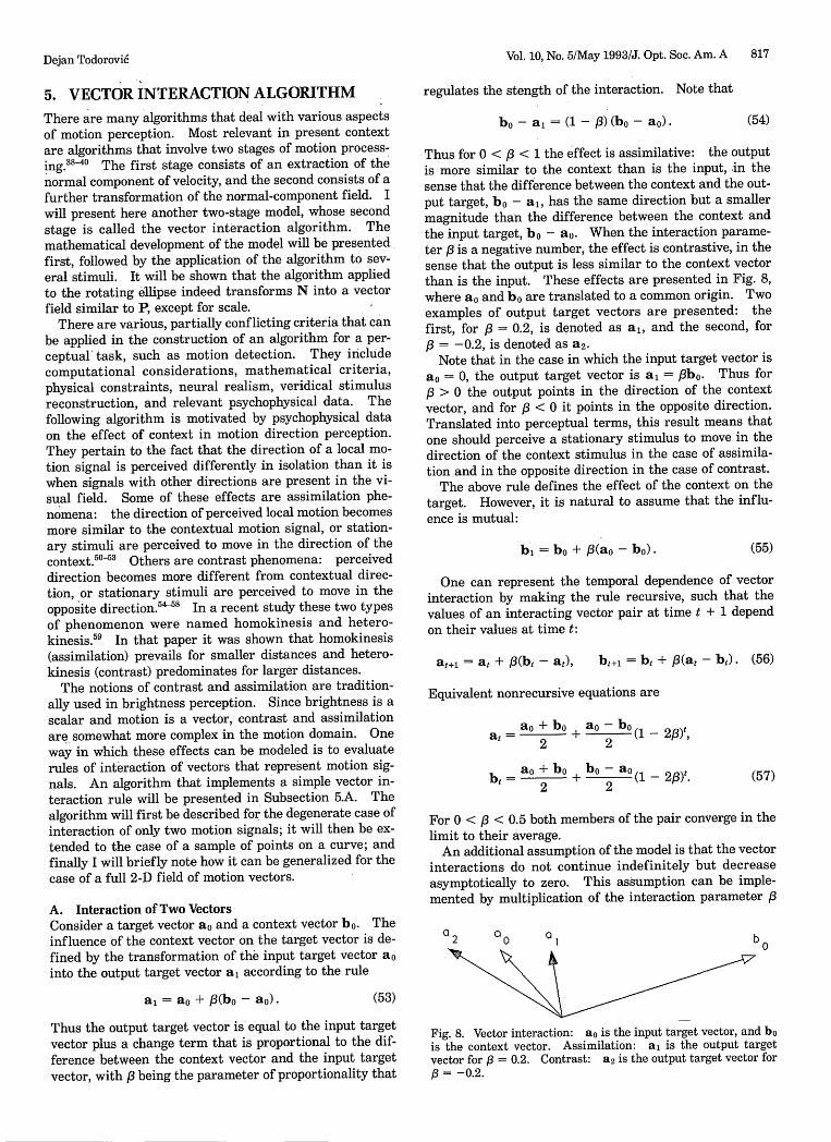
A. Interaction of Two VectorsConsider a target vector ao and a context vector bo. Theinfluence of the context vector on the target vector is de-fined by the transformation of the input target vector aointo the output target vector a, according to the rule
a, = a + /3(bo - a).
Vol. 10, No. 5/May 1993/J. Opt. Soc. Am. A 817
regulates the stength of the interaction. Note that
bo - a, = (1 - /B) (bo - a) - (54)
Thus for 0 < /3 < 1 the effect is assimilative: the outputis more similar to the context than is the input, in thesense that the difference between the context and the out-put target, bo - a,, has the same direction but a smallermagnitude than the difference between the context andthe input target, bo - a0 . When the interaction parame-ter /3 is a negative number, the effect is contrastive, in thesense that the output is less similar to the context vectorthan is the input. These effects are presented in Fig. 8,where ao and bo are translated to a common origin. Twoexamples of output target vectors are presented: thefirst, for 3 = 0.2, is denoted as a1, and the second, for,3 = -0.2, is denoted as a 2.
Note that in the case in which the input target vector isao = 0, the output target vector is a1 = /3bo. Thus for,/ > 0 the output points in the direction of the contextvector, and for /3 < 0 it points in the opposite direction.Translated into perceptual terms, this result means thatone should perceive a stationary stimulus to move in thedirection of the context stimulus in the case of assimila-tion and in the opposite direction in the case of contrast.
The above rule defines the effect of the context on thetarget. However, it is natural to assume that the influ-ence is mutual:
b = bo + /3(ao - bo). (55)
One can represent the temporal dependence of vectorinteraction by making the rule recursive, such that thevalues of an interacting vector pair at time t + 1 dependon their values at time t:
at+, = at + /3(bt - at), bt+j = bt + /3(at - b). (56)
Equivalent nonrecursive equations are
at = 2 + 0 bo (1 - 2,B)t,22bt = 2 + a (1 - 23)t.
2 2(57)
For 0 < < 0.5 both members of the pair converge in thelimit to their average.
An additional assumption of the model is that the vectorinteractions do not continue indefinitely but decreaseasymptotically to zero. This assumption can be imple-mented by multiplication of the interaction parameter /3
a 2 a0 a 1 by
(53)
Thus the output target vector is equal to the input targetvector plus a change term that is proportional to the dif-ference between the context vector and the input targetvector, with /3 being the parameter of proportionality that
Fig. 8. Vector interaction: a is the input target vector, and bois the context vector. Assimilation: a is the output targetvector for /3 = 0.2. Contrast: a2 is the output target vector for,6 = -0.2.
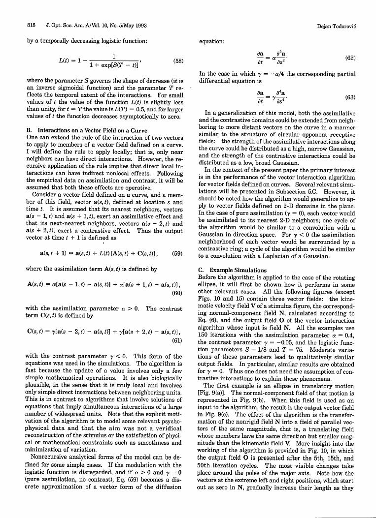
818 J. Opt. Soc. Am. A/Vol. 10, No. 5/May 1993
by a temporally decreasing logistic function:
L(t) = 1- 11 + exp[S(T - t)]
equation:
aa 82a
at y(58) (62)
where the parameter S governs the shape of decrease (it isan inverse sigmoidal function) and the parameter T re-flects the temporal extent of the interactions. For smallvalues of t the value of the function L(t) is slightly lessthan unity, for t = T the value is L(T) = 0.5, and for largervalues of t the function decreases asymptotically to zero.
B. Interactions on a Vector Field on a CurveOne can extend the rule of the interaction of two vectorsto apply to members of a vector field defined on a curve.I will define the rule to apply locally; that is, only nearneighbors can have direct interactions. However, the re-cursive application of the rule implies that direct local in-teractions can have indirect nonlocal effects. Followingthe empirical data on assimilation and contrast, it will beassumed that both these effects are operative.
Consider a vector field defined on a curve, and a mem-ber of this field, vector a(s, t), defined at location s andtime t. It is assumed that its nearest neighbors, vectorsa(s - 1, t) and a(s + 1, t), exert an assimilative effect andthat its next-nearest neighbors, vectors a(s - 2, t) anda(s + 2, t), exert a contrastive effect. Thus the outputvector at time t + 1 is defined as
a(s, t + 1) = a(s, t) + L(t) [A(s, t) + C(s, t)], (59)
In the case in which y = -a/4 the corresponding partialdifferential equation is
da a4 aa= t .a t ';s4
(63)
In a generalization of this model, both the assimilativeand the contrastive domains could be extended from neigh-boring to more distant vectors on the curve in a mannersimilar to the structure of circular opponent receptivefields: the strength of the assimilative interactions alongthe curve could be distributed as a high, narrow Gaussian,and the strength of the contrastive interactions could bedistributed as a low, broad Gaussian.
In the context of the present paper the primary interestis in the performance of the vector interaction algorithmfor vector fields defined on curves. Several relevant simu-lations will be presented in Subsection 5.C. However, itshould be noted how the algorithm would generalize to ap-ply to vector fields defined on 2-D domains in the plane.In the case of pure assimilation (y = 0), each vector wouldbe assimilated to its nearest 2-D neighbors; one cycle ofthe algorithm would be similar to a convolution with aGaussian in direction space. For y < 0 the assimilationneighborhood of each vector would be surrounded by acontrastive ring; a cycle of the algorithm would be similarto a convolution with a Laplacian of a Gaussian.
where the assimilation term A(s, t) is defined by
A(s, t) = a[a(s - 1, t) - a(s, t)] + a[a(s + 1, t) - a(s, t)],(60)
with the assimilation parameter a > 0. The contrastterm C(s, t) is defined by
C(s, t) = [a(s - 2, t) - a(s, t)] + [a(s + 2, t) - a(s, t)],(61)
with the contrast parameter y < 0. This form of theequations was used in the simulations. The algorithm isfast because the update of a value involves only a fewsimple mathematical operations. It is also biologicallyplausible, in the sense that it is truly local and involvesonly simple direct interactions between neighboring units.This is in contrast to algorithms that involve solutions ofequations that imply simultaneous interactions of a largenumber of widespread units. Note that the explicit moti-vation of the algorithm is to model some relevant psycho-physical data and that the aim was not a veridicalreconstruction of the stimulus or the satisfaction of physi-cal or mathematical constraints such as smoothness andminimization of variation.
Nonrecursive analytical forms of the model can be de-fined for some simple cases. If the modulation with thelogistic function is disregarded, and if a > 0 and y = 0(pure assimilation, no contrast), Eq. (59) becomes a dis-crete approximation of a vector form of the diffusion
C. Example SimulationsBefore the algorithm is applied to the case of the rotatingellipse, it will first be shown how it performs in someother relevant cases. All the following figures (exceptFigs. 10 and 15) contain three vector fields: the kine-matic velocity field V of a stimulus figure, the correspond-ing normal-component field N, calculated according toEq. (6), and the output field 0 of the vector interactionalgorithm whose input is field N. All the examples use150 iterations with the assimilation parameter a = 0.4,the contrast parameter y = -0.05, and the logistic func-tion parameters S = 1/8 and T = 75. Moderate varia-tions of these parameters lead to qualitatively similaroutput fields. In particular, similar results are obtainedfor y = 0. Thus one does not need the assumption of con-trastive interactions to explain these phenomena.
The first example is an ellipse in translatory motion[Fig. 9(a)]. The normal-component field of that motion isrepresented in Fig. 9(b). When this field is used as aninput to the algorithm, the result is the output vector fieldin Fig. 9(c). The effect of the algorithm is the transfor-mation of the nonrigid field N into a field of parallel vec-tors of the same magnitude, that is, a translating fieldwhose members have the same direction but smaller mag-nitude than the kinematic field V More insight into theworking of the algorithm is provided in Fig. 10, in whichthe output field 0 is presented after the 5th, 15th, and50th iteration cycles. The most visible changes takeplace around the poles of the major axis. Note how thevectors at the extreme left and right positions, which startout as zero in N, gradually increase their length as they
Dejan Todorovi6
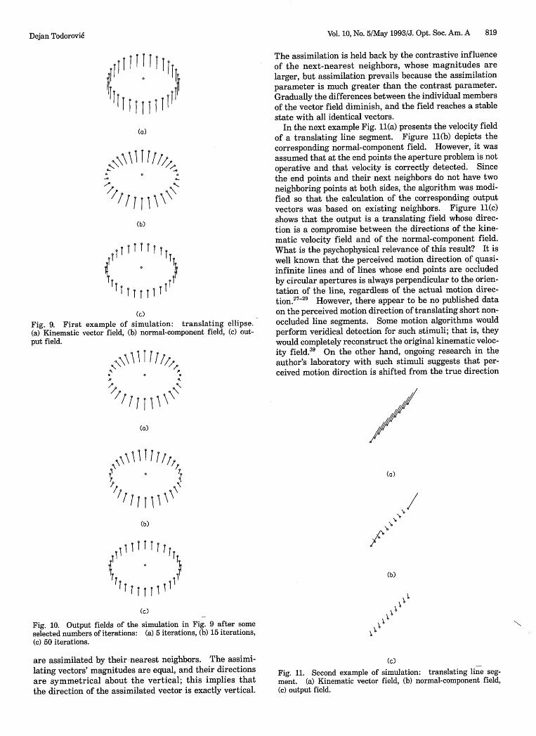
Vol. 10, No. 5/May 1993/J. Opt. Soc. Am. A 819
IT
11ITT T
T111(a)
I
(b)
T tT I ~
IT I i iT TI
(c)
Fig. 9. First example of simulation: translating ellipse.(a) Kinematic vector field, (b) normal-component field, (c) out-put field.
I II/
The assimilation is held back by the contrastive influenceof the next-nearest neighbors, whose magnitudes arelarger, but assimilation prevails because the assimilationparameter is much greater than the contrast parameter.Gradually the differences between the individual membersof the vector field diminish, and the field reaches a stablestate with all identical vectors.
In the next example Fig. 11(a) presents the velocity fieldof a translating line segment. Figure 11(b) depicts thecorresponding normal-component field. However, it wasassumed that at the end points the aperture problem is notoperative and that velocity is correctly detected. Sincethe end points and their next neighbors do not have twoneighboring points at both sides, the algorithm was modi-fied so that the calculation of the corresponding outputvectors was based on existing neighbors. Figure 11(c)shows that the output is a translating field whose direc-tion is a compromise between the directions of the kine-matic velocity field and of the normal-component field.What is the psychophysical relevance of this result? It iswell known that the perceived motion direction of quasi-infinite lines and of lines whose end points are occludedby circular apertures is always perpendicular to the orien-tation of the line, regardless of the actual motion direc-tion.2 7 29 However, there appear to be no published dataon the perceived motion direction of translating short non-occluded line segments. Some motion algorithms wouldperform veridical detection for such stimuli; that is, theywould completely reconstruct the original kinematic veloc-ity field.39 On the other hand, ongoing research in theauthor's laboratory with such stimuli suggests that per-ceived motion direction is shifted from the true direction
' /1
(a)
c/e\ 1 / bI T It
(b)
5 'II I T T t TT
(c)
Fig. 10. Output fields of the simulation in Fig. 9 after someselected numbers of iterations: (a) 5 iterations, (b) 15 iterations,(c) 50 iterations.
are assimilated by their nearest neighbors. The assimi-lating vectors' magnitudes are equal, and their directionsare symmetrical about the vertical; this implies thatthe direction of the assimilated vector is exactly vertical.
(a)
(b)
\\ I
(c)
Fig. 11. Second example of simulation: translating line seg-ment. (a) Kinematic vector field, (b) normal-component field,(c) output field.
Dejan Todorovi6
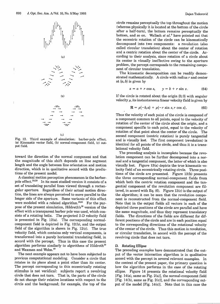
820 J. Opt. Soc. Am. A/Vol. 10, No. 5/May 1993
1 1 1 .1 1 1 ± 1 1 I I . I1 Tl I Id I jflI ! l
(a)
1_ -O -. ,
11. /1.
circle remains perceptually the top throughout the motion(whereas physically it is located at the bottom of the circleafter a half-turn), the bottom remains perceptually thebottom, and so on. Wallach et al.8 have pointed out thatthe eccentric rotation of the circle can be kinematicallydecomposed into two components: a revolution (alsocalled circular translation) about the center of rotationand a centric rotation about the center of the circle. Ac-cording to their analysis, since rotation of a circle aboutits center is visually ineffective owing to the apertureproblem, the percept corresponds to the remaining compo-nent of circular translation.
The kinematic decomposition can be readily demon-strated mathematically. A circle with radius r and centerat {a, b} is given by
x = a + r cos s, y = b + r sin s. (64)
If the circle is rotated about the origin {0, 0} with angularvelocity p, its instantaneous linear velocity field is given by
R = p{-ba} + p{-r sin s,r coss}.
Cc)Fig. 12. Third example of simulation: barber-pole effect.(a) Kinematic vector field, (b) normal-component field, (c) out-put field.
toward the direction of the normal component and thatthe magnitude of this shift depends on line segmentlength and the angle between line orientation and motiondirection, which is in qualitative accord with the predic-tions of the present model.
A classical motion perception phenomenon is the barber-pole effect.2 8' 29 In its most studied version it consists of aset of translating parallel lines viewed through a rectan-gular aperture. Regardless of their actual motion direc-tion, the lines are always perceived to move parallel to thelonger side of the aperture. Some variants of this effectwere modeled with a related algorithm.60 ' 6 For the pur-pose of the present simulation, Hildreth's"9 version of theeffect with a transparent barber pole was used, which con-sists of a rotating helix. The projected 2-D velocity fieldis presented in Fig. 12(a). The corresponding normal-component field is depicted in Fig. 12(b), and the outputfield of the algorithm is shown in Fig. 12(c). The truevelocity field, which contains only vertical components, istransformed into a purely horizontal translating field, inaccord with the percept. Thus in this case the presentalgorithm performs similarly to algorithms of Hildreth3 9
and Waxman and Wohn.4 0
The next example appears not to have been subjected toprevious computational modeling. Consider a circle thatrotates in its plane about a point other than its center.The percept corresponding to this eccentrically rotatingstimulus is not veridical: subjects report a revolvingcircle that does not turn. That is, the parts of the circledo not change their relative locations with respect to thecircle and the background; for example, the top of the
(65)
Thus the velocity of each point of the circle is composed ofa component common to all points, equal to the velocity ofrotation of the center of the circle about the origin, and acomponent specific to each point, equal to the velocity ofrotation of that point about the center of the circle. Thesecond component (centric rotation) is purely tangentialand is visually lost. The first component (revolution) isidentical for all points of the circle, and thus it is a trans-lational velocity field.
The preceding analysis is incomplete because the revo-lution component can be further decomposed into a nor-mal and a tangential component, the latter of which is alsovisually lost. Figure 13(a) depicts the true kinematic ve-locity field of an eccentrically rotating circle. Three posi-tions of the circle are presented. Figure 13(b) presentsthe three corresponding normal-component fields fromwhich both the centric rotation component and the tan-gential component of the revolution component are fil-tered, in accord with Eq. (6). Figure 13(c) is the output ofthe algorithm; it can be seen that the revolution compo-nent is reconstructed from the normal-component field.Note that in the output fields all vectors in each of thedepicted three positions of the circle are parallel and havethe same magnitude, and thus they represent translatoryfields. The directions of the fields are different for dif-ferent positions of the circle and are in each position equalto the corresponding directions of the rotational velocityof the center of the circle. Thus this motion is revolution,or circular translation, in accord with the percept of therevolving circle that does not turn.
D. Rotating EllipseThe preceding examples have demonstrated that the out-put of the vector interaction algorithm is in qualitativeaccord with the percept in several relevant examples. Inthe context of the present paper, the primary question ishow the algorithm performs in the case of the rotatingellipse. Figure 14 presents the rotational velocity field[Fig. 14(a), same as Fig. 2(a)], the normal-component field[Fig. 14(b), same as Fig. 2(c)], and the corresponding out-put of the model [Fig. 14(c)]. Note that in this case the
(b)
Dejan Todorovi6
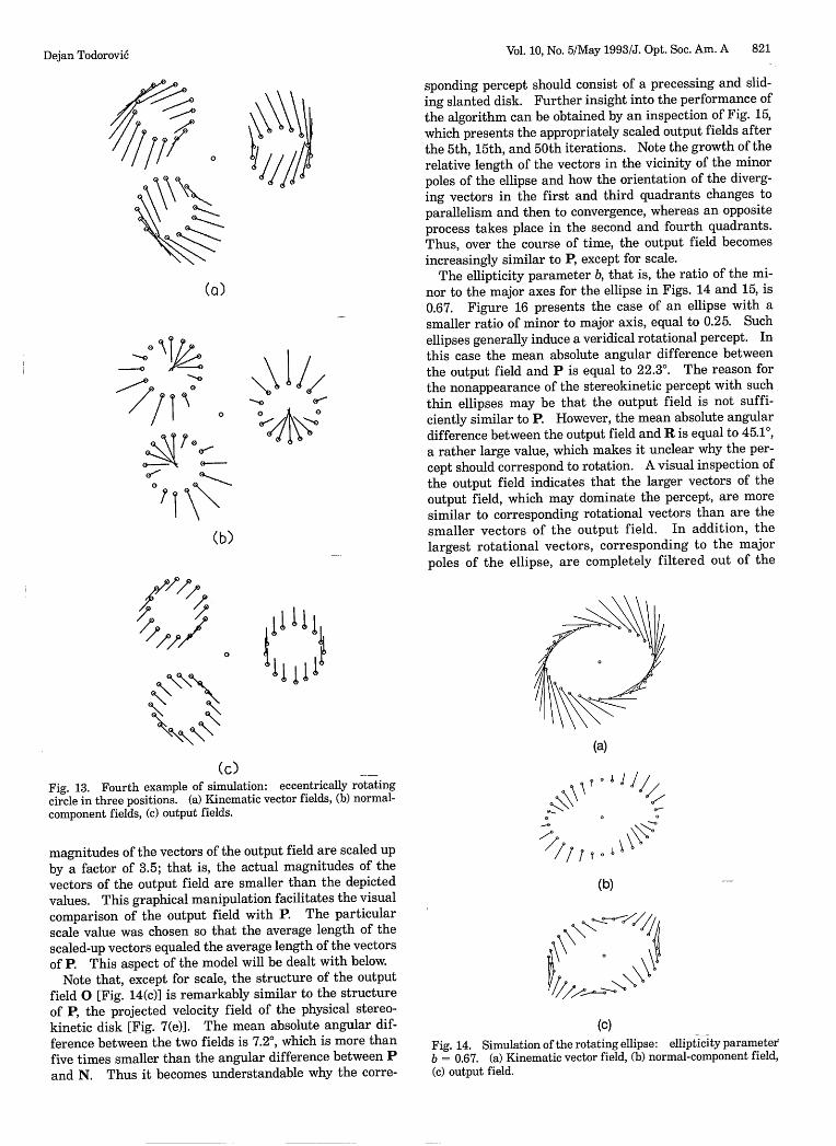
Vol. 10, No. 5/May 1993/J. Opt. Soc. Am. A 821
sponding percept should consist of a precessing and slid-ing slanted disk. Further insight into the performance ofthe algorithm can be obtained by an inspection of Fig. 15,which presents the appropriately scaled output fields afterthe 5th, 15th, and 50th iterations. Note the growth of therelative length of the vectors in the vicinity of the minorpoles of the ellipse and how the orientation of the diverg-ing vectors in the first and third quadrants changes toparallelism and then to convergence, whereas an oppositeprocess takes place in the second and fourth quadrants.Thus, over the course of time, the output field becomesincreasingly similar to P, except for scale.
The ellipticity parameter b, that is, the ratio of the mi-nor to the major axes for the ellipse in Figs. 14 and 15, is0.67. Figure 16 presents the case of an ellipse with asmaller ratio of minor to major axis, equal to 0.25. Suchellipses generally induce a veridical rotational percept. Inthis case the mean absolute angular difference betweenthe output field and P is equal to 22.3°. The reason forthe nonappearance of the stereokinetic percept with suchthin ellipses may be that the output field is not suffi-ciently similar to P. However, the mean absolute angulardifference between the output field and R is equal to 45.1°,a rather large value, which makes it unclear why the per-cept should correspond to rotation. A visual inspection ofthe output field indicates that the larger vectors of theoutput field, which may dominate the percept, are moresimilar to corresponding rotational vectors than are thesmaller vectors of the output field. In addition, thelargest rotational vectors, corresponding to the majorpoles of the ellipse, are completely filtered out of the
(c)Fig. 13. Fourth example of simulation: eccentrically rotatingcircle in three positions. (a) Kinematic vector fields, (b) normal-component fields, (c) output fields.
magnitudes of the vectors of the output field are scaled upby a factor of 3.5; that is, the actual magnitudes of the
vectors of the output field are smaller than the depictedvalues. This graphical manipulation facilitates the visualcomparison of the output field with P. The particularscale value was chosen so that the average length of the
scaled-up vectors equaled the average length of the vectorsof P. This aspect of the model will be dealt with below.
Note that, except for scale, the structure of the outputfield 0 [Fig. 14(c)] is remarkably similar to the structureof P, the projected velocity field of the physical stereo-kinetic disk [Fig. 7(e)]. The mean absolute angular dif-ference between the two fields is 7.20, which is more thanfive times smaller than the angular difference between Pand N. Thus it becomes understandable why the corre-
(a)
\ \ ° I /11X
(b)
(c)
Fig. 14. Simulation of the rotating ellipse: ellipticity parameterb = 0.67. (a) Kinematic vector field, (b) normal-component field,(c) output field.
(a)
9 TS
.0
//I7 9
of_ I so o x o~0~
04Aj9
(b)
Dejan Todorovi6
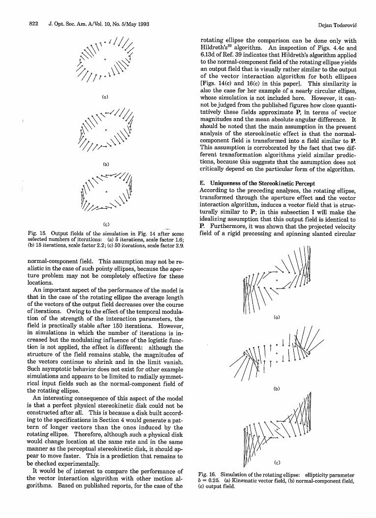
822 J. Opt. Soc. Am. A/Vol. 10, No. 5/May 1993
is J //
/ I
(a)
(b)
Cc)
Fig. 15. Output fields of the simulation in Fig. 14 after someselected numbers of iterations: (a) 5 iterations, scale factor 1.6;(b) 15 iterations, scale factor 2.2; (c) 50 iterations, scale factor 2.9.
normal-component field. This assumption may not be re-alistic in the case of such pointy ellipses, because the aper-ture problem may not be completely effective for theselocations.
An important aspect of the performance of the model isthat in the case of the rotating ellipse the average lengthof the vectors of the output field decreases over the courseof iterations. Owing to the effect of the temporal modula-tion of the strength of the interaction parameters, thefield is practically stable after 150 iterations. However,in simulations in which the number of iterations is in-creased but the modulating influence of the logistic func-tion is not applied, the effect is different: although thestructure of the field remains stable, the magnitudes ofthe vectors continue to shrink and in the limit vanish.Such asymptotic behavior does not exist for other examplesimulations and appears to be limited to radially symmet-rical input fields such as the normal-component field ofthe rotating ellipse.
An interesting consequence of this aspect of the modelis that a perfect physical stereokinetic disk could not beconstructed after all. This is because a disk built accord-ing to the specifications in Section 4 would generate a pat-tern of longer vectors than the ones induced by therotating ellipse. Therefore, although such a physical diskwould change location at the same rate and in the samemanner as the perceptual stereokinetic disk, it should ap-pear to move faster. This is a prediction that remains tobe checked experimentally.
It would be of interest to compare the performance ofthe vector interaction algorithm with other motion al-gorithms. Based on published reports, for the case of the
rotating ellipse the comparison can be done only withHildreth's39 algorithm. An inspection of Figs. 4.4c and6.13d of Ref. 39 indicates that Hildreth's algorithm appliedto the normal-component field of the rotating ellipse yieldsan output field that is visually rather similar to the outputof the vector interaction algorithm for both ellipses[Figs. 14(c) and 16(c) in this paper]. This similarity isalso the case for her example of a nearly circular ellipse,whose simulation is not included here. However, it can-not be judged from the published figures how close quanti-tatively these fields approximate P in terms of vectormagnitudes and the mean absolute angular difference. Itshould be noted that the main assumption in the presentanalysis of the stereokinetic effect is that the normal-component field is transformed into a field similar to P.This assumption is corroborated by the fact that two dif-ferent transformation algorithms yield similar predic-tions, because this suggests that the assumption does notcritically depend on the particular form of the algorithm.
E. Uniqueness of the Stereokinetic PerceptAccording to the preceding analyses, the rotating ellipse,transformed through the aperture effect and the vectorinteraction algorithm, induces a vector field that is struc-turally similar to P; in this subsection I will make theidealizing assumption that this output field is identical toP. Furthermore, it was shown that the projected velocityfield of a rigid precessing and spinning slanted circular
(a)
I11
(b)
(c)
Fig. 16. Simulation of the rotating ellipse: ellipticity parameterb = 0.25. (a) Kinematic vector field, (b) normal-component field,(c) output field.
Dejan Todorovic
I
I
I
I
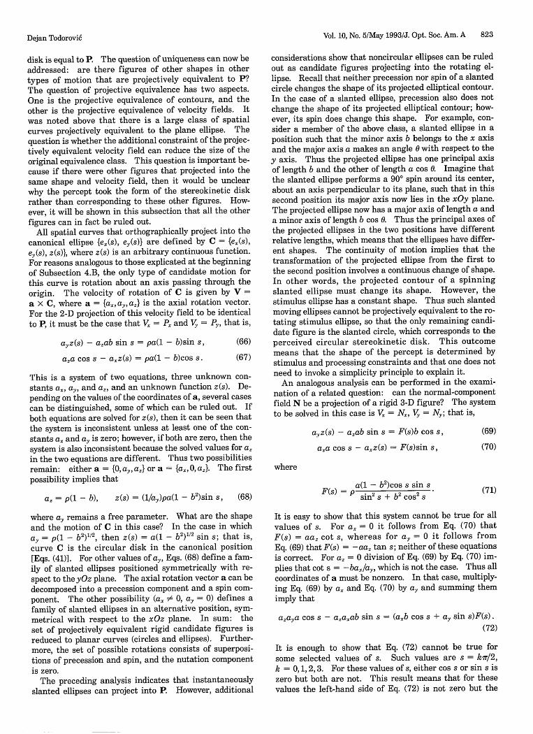
Vol. 10, No. 5/May 1993/J. Opt. Soc. Am. A 823
disk is equal to P. The question of uniqueness can now beaddressed: are there figures of other shapes in othertypes of motion that are projectively equivalent to P?The question of projective equivalence has two aspects.One is the projective equivalence of contours, and theother is the projective equivalence of velocity fields. Itwas noted above that there is a large class of spatialcurves projectively equivalent to the plane ellipse. Thequestion is whether the additional constraint of the projec-tively equivalent velocity field can reduce the size of theoriginal equivalence class. This question is important be-cause if there were other figures that projected into thesame shape and velocity field, then it would be unclearwhy the percept took the form of the stereokinetic diskrather than corresponding to these other figures. How-ever, it will be shown in this subsection that all the otherfigures can in fact be ruled out.
All spatial curves that orthographically project into thecanonical ellipse {e2(s), ey(s)} are defined by C = {ex(s),ey(s), z(s)}, where z(s) is an arbitrary continuous function.For reasons analogous to those explicated at the beginningof Subsection 4.B, the only type of candidate motion forthis curve is rotation about an axis passing through theorigin. The velocity of rotation of C is given by V =
a X C, where a = {a,, ayaz} is the axial rotation vector.For the 2-D projection of this velocity field to be identicalto P, it must be the case that Vx = Px and V, = P, that is,
ayz(s) - azab sin s = pa(l - b)sin s, (66)
aza cos s - axz(s) = pa(l - b)cos s. (67)
This is a system of two equations, three unknown con-
stants a., ay, and az, and an unknown function z(s). De-pending on the values of the coordinates of a, several casescan be distinguished, some of which can be ruled out. Ifboth equations are solved for z(s), then it can be seen thatthe system is inconsistent unless at least one of the con-stants a. and ay is zero; however, if both are zero, then thesystem is also inconsistent because the solved values for azin the two equations are different. Thus two possibilitiesremain: either a = {0, ay, az} or a = {a., 0, a.}. The firstpossibility implies that
az = p(l - b), z(s) = (1/ay)pa(1 - b2 )sin s, (68)
where ay remains a free parameter. What are the shapeand the motion of C in this case? In the case in whichay = p(l - b2)"2, then z(s) = a(1 - b2)"2 sin s; that is,curve C is the circular disk in the canonical position[Eqs. (41)]. For other values of ay, Eqs. (68) define a fam-ily of slanted ellipses positioned symmetrically with re-spect to the yOz plane. The axial rotation vector a can bedecomposed into a precession component and a spin com-ponent. The other possibility (ax # 0, ay = 0) defines afamily of slanted ellipses in an alternative position, sym-metrical with respect to the xOz plane. In sum: theset of projectively equivalent rigid candidate figures isreduced to planar curves (circles and ellipses). Further-more, the set of possible rotations consists of superposi-tions of precession and spin, and the nutation componentis zero.
The preceding analysis indicates that instantaneouslyslanted ellipses can project into P. However, additional
considerations show that noncircular ellipses can be ruledout as candidate figures projecting into the rotating el-lipse. Recall that neither precession nor spin of a slantedcircle changes the shape of its projected elliptical contour.In the case of a slanted ellipse, precession also does notchange the shape of its projected elliptical contour; how-ever, its spin does change this shape. For example, con-sider a member of the above class, a slanted ellipse in aposition such that the minor axis b belongs to the x axisand the major axis a makes an angle 0 with respect to they axis. Thus the projected ellipse has one principal axisof length b and the other of length a cos 0. Imagine thatthe slanted ellipse performs a 900 spin around its center,about an axis perpendicular to its plane, such that in thissecond position its major axis now lies in the xOy plane.The projected ellipse now has a major axis of length a anda minor axis of length b cos 0. Thus the principal axes ofthe projected ellipses in the two positions have differentrelative lengths, which means that the ellipses have differ-ent shapes. The continuity of motion implies that thetransformation of the projected ellipse from the first tothe second position involves a continuous change of shape.In other words, the projected contour of a spinningslanted ellipse must change its shape. However, thestimulus ellipse has a constant shape. Thus such slantedmoving ellipses cannot be projectively equivalent to the ro-tating stimulus ellipse, so that the only remaining candi-date figure is the slanted circle, which corresponds to theperceived circular stereokinetic disk. This outcomemeans that the shape of the percept is determined bystimulus and processing constraints and that one does notneed to invoke a simplicity principle to explain it.
An analogous analysis can be performed in the exami-nation of a related question: can the normal-componentfield N be a projection of a rigid 3-D figure? The systemto be solved in this case is Vx = N2, Vy = N,; that is,
ayz(s) - aab sin s = F(s)b cos s,
aza cos s - axz(s) = F(s)sin s,
(69)
(70)
where
(71)a(l - b2 )cos s sin s
F~)=Psin 2 S + b 2 Cos 2
It is easy to show that this system cannot be true for allvalues of s. For ax = 0 it follows from Eq. (70) thatF(s) = aaz cot s, whereas for ay = 0 it follows fromEq. (69) that F(s) = -aaz tan s; neither of these equationsis correct. For a, = 0 division of Eq. (69) by Eq. (70) im-plies that cot s = -ba2 /a, which is not the case. Thus allcoordinates of a must be nonzero. In that case, multiply-ing Eq. (69) by ax and Eq. (70) by a, and summing themimply that
azaya cos s - azaab sin s = (ab cos s + ay sin s)F(s).
(72)
It is enough to show that Eq. (72) cannot be true forsome selected values of s. Such values are s = kiT12,k = 0, 1, 2, 3. For these values of s, either cos s or sin s iszero but both are not. This result means that for thesevalues the left-hand side of Eq. (72) is not zero but the
Dejan Todorovic
824 J. Opt. Soc. Am. A/Vol. 10, No. 5/May 1993
right-hand side is zero, because F(s) contains the termcos s sin s in the numerator. In conclusion, N cannot be
the orthographic projection of any rigid rotating figure.
6. DISCUSSION
How does a rotating ellipse induce three qualitatively dif-
ferent percepts? The main results of this paper are the
mathematical analyses of the conditions of the nonveridi-
cal percepts. The basic cause of these percepts is the fact
that motion of a body, regarded as a physical phenomenon
studied in kinematics, is not equivalent to motion as a
stimulus studied in visual psychophysics. The reason is
that kinematic motion must be visually specified as an
optical transformation. Problems arise when this trans-
formation does not faithfully represent the underlyingkinematics. Such is the case when the optical velocity
vector field differs from the kinematic velocity vector
field. The aperture problem is an example of such a case.
The visual relevance of the mathematical decompositionof the kinematic velocity vector field into tangential and
normal components is based on the assumption that, for
optical (that is, nonkinematic) reasons, the tangentialcomponent is lost in the optical velocity vector field.
The main aspect of the amoeboid percept is the fact
that a rigid flat stimulus induces a nonrigid flat percept.Following previous studies,''39 it was assumed that, owing
to the aperture problem, the effective stimulus is not the
rigid rotational velocity field R but the normal-componentfield N. Two analytical tests have confirmed the non-
rigidity of N. According to the test based on the temporal
derivative of curvature, the normal-component field in-
duces a decrease of curvature in two quadrants of the el-
lipse and an increase of curvature in the other two
quadrants. Such curvature changes appear to be in quali-
tative accord with the percept of the rotating deformingellipse, but one would need to conduct additional psycho-
physical studies to examine whether the structure of the
perceived nonrigidity is equivalent to the structure of geo-metrical nonrigidity.
The main aspect of the stereokinetic percept is the pe-culiar rolling motion of a circular rigid disk. The analy-
sis in Section 4 has established the geometrical and
kinematic characteristics of this motion. An attractivelysimple explanation of the stereokinetic percept is that thispercept, like the amoeboid percept, is also based on N.However, a further analysis has shown that the projectedvelocity field P of the physical stereokinetic disk is differ-
ent from N. After a discussion of several possibilities,an approach was taken in which it was assumed that thenormal-component field is subject to further transforma-tions. An algorithm was described that performs such a
transformation. Several examples of the performance of
this algorithm have shown that its output field is in quali-
tative accord with the corresponding percept. Further-more, it was demonstrated that the output of the algorithmfor the case of the rotating ellipse is structurally similarto P, except for scale. Thus the following explanation ofthe stereokinetic percept is offered: the percept looks
as it does because the stimulus caused by the rotating el-lipse, after being subjected to an optical transformation(owing to the aperture effect) and a neural transformation(modeled by the vector interaction algorithm), results in a
perceptual state similar to the one induced by a precessingand spinning rigid slanted circular disk.
The preceding account of the percepts induced by therotating ellipse is incomplete for several reasons. For ex-
ample, in view of the aperture problem it is not clear why
the veridical percept should exist at all. One possibility isthat some irregularities in the initially stationary stimu-lus, such as isolated blobs for which the perceived motion
direction does not suffer from the aperture problem, pro-vide clues for the veridical perception of the stimulus.This conjecture would agree with the fact that the onset ofthe amoeboid percept is speeded up when the stimulus isalready rotating at first exposure to the subject.8" 9 How-ever, the initial veridical percept is also present in com-puter representations of the rotating ellipse, where thestimulus should be free from irregularities. It is also not
clear why it takes inexperienced subjects longer, and some-times only after the suggestion of the experimenter, toperceive the stereokinetic percept.' One may speculatethat some processes of learning and attention influencethe neural algorithms that underlie the perceptual effects.
Another problem concerns the transition from theamoeboid to the stereokinetic percept. In the present ap-proach the first percept is associated with N and the sec-ond is associated with a field closely approximating P.
However, it can be formally verified, with the help of the
two tests discussed in Section 3, that the field P is a non-rigid 2-D field. Why then does the percept change from
amoeboid (nonrigid 2-D) to stereokinetic (rigid 3-D) when
both N and P could support a nonrigid 2-D percept?One could explain this transition not by treating N as a
mere intermediate computational step but by granting itneural reality. The consequence of the vector interactionalgorithm applied to N is the gradual transformation of Ninto P. If it is assumed that N corresponds to a distribu-tion of neural activity in a motion-sensitive cortical areaand that P corresponds to another activity distribution,then the intermediate vector fields would correspond tointermediate activity distributions. The amoeboid per-cept would correspond to the earlier members of this se-quence of distributions, and the stereokinetic perceptwould correspond to the later members. This explanationagrees with the psychophysical finding that the amoeboidpercept regularly precedes the stereokinetic percept.The switch from one percept to the other would occurwhen the corresponding vector field becomes sufficientlysimilar to P. This switch would be an instance of therigidity constraint,6 3 according to which a rigid interpre-
tation is favored over a nonrigid interpretation in the casein which both are consistent with the stimulus. Thisapproach agrees with the fact demonstrated in Subsec-tion 5.E that N cannot be the projection of any rigid rotat-ing figure and that the only rigid figure consistent with Pis the slanted precessing spinning circular disk. Theanalysis in Subsection 5.E is limited to rigid figures anddoes not rule out nonrigid 3-D figures that could also beconsistent with the stimulus, such as slanted ellipses thatperform elliption (as defined in subsection 3.C). However,such figures are also ruled out by the rigidity constraint.
Note a difference between the present approach and theapproach of Hildreth.' 9 She deals with an impressive va-riety of motion phenomena, but in her analysis of the ro-tating ellipse the stereokinetic percept is not addressed.
Dejan Todorovi6

Vol. 10, No. 5/May 1993/J. Opt. Soc. Am. A 825
The nonrigidity of the amoeboid percept is explained bythe nonrigidity of the output field of her algorithm, which,as noted above, is similar to P. However, if the amoeboidpercept is based on P, then it is unclear on what the stereo-kinetic percept should be based. Thus one advantage of
the present approach is that it assigns different bases to
different percepts. In addition, this approach suggeststhat the spontaneous shifts between the amoeboid and
stereokinetic percepts are due to fluctuations of thestrength of vectorial interactions: weak interactions(small a and y) would only marginally change the inputfield N.
Finally, it should be pointed out that the present analy-sis is concerned with only a simple version of the stereo-kinetic effect. There are many other stimuli, besides the
rotating ellipse, that induce related nonveridical 2-D and
3-D percepts, the most studied case being the stereo-kinetic cone.72564 It remains to be seen whether the
present approach is useful in the analysis of other variantsof the effect.
ACKNOWLEDGMENTS
I wish to thank Jack Loomis, Milog Miljkovi6, and an
anonymous referee for their comments and help. The
author's mailing address is Department of Psychology,Laboratory of Experimental Psychology, Cika Ljubina18-20, 11000 Belgrade, Serbia, Yugoslavia (E-mail:[email protected]).
REFERENCES
1. A. Schwartz, The Complete Works of Marcel Duchamp(Abrams, New York, 1970).
2. C. L. Musatti, "Sui fenomeni stereocinetici," Arch. Ital.Psicol. 3, 105-120 (1924).
3. F. S. Duncan, "Kinetic art: on my psychokinetic objects,"
Leonardo 8, 97-101 (1975).4. P. Renvall, "Zur Theorie des stereokinetischen Phiinomens,"
Ann. Univ. Aboensis Ser. B 10, 1-75 (1929).
5. C. L. Musatti, "La stereocinesi e il problema della struttura
dello spazio visibile," Rev. Psicol. 49, 3-57 (1955).
6. C. L. Musatti, "Stereokinetic phenomena and their interpre-tation," in Studies in Perception: Festschrift for FabioMetelli, G. B. Flores D'Arcais, ed. (Martello-Giunti, Milan,1975).
7. G. J. Fischer, "Factors affecting estimation of depth withvariations of the stereo-kinetic effect," Am. J. Psychol. 69,252-257 (1956).
8. H. Wallach, A. Weisz, and P. Adams, "Circles and derived fig-
ures in rotation," Am. J. Psychol. 69, 48-59 (1956).9. R. B. Mefferd and B. A. Wieland, "Perception of depth in ro-
tating objects: 2. Perspective as a determinant of stereo-
kinesis," Percept. Mot. Skills 25, 621-628 (1967).
10. N. Fineman, The Inquisitive Eye (Oxford U. Press, Oxford,
1981).11. N. Wade, The Art and Science of Visual Illusions (Routledge
& Kegan Paul, London, 1982).12. J. A. Wilson, J. 0. Robinson, and D. J. Piggins, "Wobble cones
and wobble holes: the stereokinetic effect revisited," Per-ception 12, 187-193 (1983).
13. J. 0. Robinson, D. J. Piggins, and J. A. Wilson, "Shape, heightand angular movement in stereokinesis," Perception 14,677-683 (1985).
14. J. A. Wilson, J. 0. Robinson, and D. J. Piggins, 'Apparentheight of a stereokinetic cone is decreased by departure from
circularity," Perception 15, 399-403 (1986).15. G. Vallortigara, P. Bressan, and M. Zanforlin, "The saturn
illusion: a new stereokinetic effect," Vision Res. 26, 811-
813 (1986).
16. P. Bressan and G. Vallortigara, "Stereokinesis with movingvisual phantoms," Perception 16, 73-78 (1987).
17. M. Zanforlin, "The height of a stereokinetic cone: a quanti-tative determination of a 3-D effect from 2-D moving pat-terns without a 'rigidity assumption,"' Psychol. Res. 50,162-172 (1988).
18. H. Wallach and N. M. Centrella, "Identity imposition and itsrole in a stereokinetic effect," Percept. Psychophys. 48, 535-542 (1990).
19. P. Bressan and G. Vallortigara, "Multiple 3-D interpretationsin a classic stereokinetic effect," Perception 15, 405-408(1986).
20. P. Bressan and G. Vallortigara, "Subjective contours can pro-duce stereokinetic effects," Perception 15, 409-412 (1986).
21. R. B. Mefferd and B. A. Wieland, "Perception of depth in ro-
tating objects: 1. Stereokinesis and the vertical-horizontalillusion," Percept. Mot. Skills 25, 93-100 (1967).
22. B. A. Wieland and R. B. Mefferd, "Perception of depth in ro-tating objects: 3. Asymmetry and velocity as the determi-nants of the stereokinetic effect," Percept. Mot. Skills 25,671-678 (1968).
23. R. B. Mefferd, "Perception of depth in rotating objects:4. Fluctuating stereokinetic variants," Percept. Mot. Skills25, 255-276 (1968).
24. R. B. Mefferd, "Perception of depth in rotating objects:5. Phenomenal motion in stereokinesis," Percept. Mot. Skills25, 903-926 (1968).
25. V Benussi, "Zur experimentellen Grundlegung hypno-sugges-tiver Methoden psychischer Analyse," Psychol. Forsch. 9,197-274 (1927).
26. H. Wallach and D. N. O'Connel, "The kinetic depth effect,"J. Exp. Psychol. 45, 205-217 (1953).
27. P. Stumpf, "Uber die Abhdngigkeit der visuellen Bewe-gungsempfindung und ihres negativen Nachbildes von denReizvorgiingen auf der Netzhaut," Z. Psychol. 59, 321-330(1911).
28. H. Wallach, "Uber visuell wahrgenommene Bewegungsrich-tung," Psychol. Forsch. 20, 325-380 (1935).
29. H. Wallach, "The direction of motion of straight lines," inOn Perception, H. Wallach, ed. (Quadrangle, New York, 1976).
30. T. R. Scott and J. H. Noland, "Some stimulus dimensions ofrotating spirals," Psychol. Rev. 72, 344-357 (1965).
31. W Metzger, Gesetze des Sehens, 2nd ed. (Waldemar Kramer,Frankfurt, Germany, 1953).
32. M. Wertheimer, "Experimentelle Studien fiber das Sehen vonBewegung," Z. Psychol. 61, 161-265 (1912).
33. D. Marr and S. Ullman, "Directional sensitivity and its usein early visual processing," Proc. R. Soc. London Ser. B 211,151-180 (1981).
34. E. A. Adelson and J. A. Movshon, "Phenomenal coherence of
moving visual patterns," Nature (London) 300, 523-525(1982).
35. E. C. Hildreth and C. Koch, "The analysis of visual motion:
from computational theory to neuronal mechanisms," Ann.Rev. Neurosci. 10, 477-533 (1987).
36. K. Nakayama and G. H. Silverman, "The aperture problem-I. Perception of nonrigidity and motion direction in trans-lating sinusoidal lines," Vision Res. 28, 739-746 (1988).
37. K. Nakayama and G. H. Silverman, "The aperture problem-II. Spatial integration of velocity information along con-tours," Vision Res. 28, 747-753 (1988).
38. A. L. Yuille and N. M. Grzywacz, 'A computational theory for
the perception of coherent visual motion," Nature (London)333, 71-74 (1988).
39. E. C. Hildreth, The Measurement of Visual Motion (MITPress, Cambridge, Mass., 1984).
40. A. M. Waxman and K. Wohn, "Image flow theory: a frame-
work for 3-D inference from time-varying imagery," in Ad-vances in Computer Vision: Vol. 1, C. M. Brown, ed. (LEA,
Hillsdale, N.J., 1988).41. B. K. P. Horn and B. G. Schunk, "Determining optical flow,"
Artif. Intell. 17, 185-203 (1981).42. W Reichardt, M. Egelhaaf, and R. W Schlogl, "Movement de-
tectors provide sufficient information for local computationof 2-D velocity field," Naturwissenschaften 75, 313-315(1988).
43. J. T. Todd and J. F. Norman, "The visual perception of
Dejan Todorovi6
826 J. Opt. Soc. Am. A/Vol. 10, No. 5/May 1993 Dejan Todorovi6
smoothly curved surfaces from minimal apparent motion se-quences," Percept. Psychophys. 50, 509-523 (1991).
44. B. A. Dosher, M. S. Landy, and G. Sperling, "Ratings of ki-netic depth in multidot displays," J. Exp. Psychol. 15, 816-825 (1989).
45. J. M. Loomis and D. W Eby, "Perceiving structure frommotion: failure of shape constancy," in Proceedings of theSecond International Conference on Computer Vision, (In-stitute of Electrical Engineers, New York, 1988), pp. 383-391.
46. G. E. Mase, Schaum's Outline of Theory and Problems ofContinuum Mechanics (McGraw-Hill, New York, 1970).
47. J. J. Koenderink and A. J. van Doorn, "Local Structure ofmovement parallax of the plane," J. Opt. Soc. Am. 66, 717-723 (1976).
48. J. J. Koenderink, "Optic flow," Vision Res. 26, 161-180 (1986).49. A. Verri, F. Girosi, and V Torre, "Differential techniques for
optical flow," J. Opt. Soc. Am. A 7, 912-922 (1990).50. V S. Ramachandran and P. Cavanagh, "Motion capture aniso-
tropy," Vision Res. 27, 97-106 (1987).51. V S. Ramachandran and V Inada, "Spatial phase and fre-
quency in motion capture of random-dot patterns," SpatialVis. 1, 57-67 (1985).
52. D. Williams and G. Phillips, "Cooperative phenomena in theperception of motion direction," J. Opt. Soc. Am. A 4, 878-885 (1987).
53. D. Williams, G. Phillips, and R. Sekuler, "Hysteresis in theperception of motion direction as evidence for neural coopera-tivity," Nature (London) 324, 253-255 (1986).
54. R. H. Day, "Induced rotations with concentric patterns,"Percept. Psychophys. 29, 493-499 (1981).
55. K. Duncker, "Uber induzierte Bewegung," Psychol. Forsch.12, 180-259 (1929).
56. J. M. Loomis and K. Nakayama, 'A velocity analogue ofbrightness contrast," Perception 2, 425-428 (1973).
57. W Marshak and R. Sekuler, "Mutual repulsion between mov-ing targets," Science 205, 1399-1401 (1979).
58. P. Tynan and R. Sekuler, "Simultaneous motion con-trast: velocity, sensitivity, and depth response," Vision Res.15, 1231-1238 (1975).
59. M. Nawrot and R. Sekuler, 'Assimilation and contrast inmotion perception: explorations in cooperativity," VisionRes. 30, 1439-1451 (1990).
60. D. Todorovi6, "Bi-stable motion percepts in crossed barber-poles: a psychophysical study and a neural network model,"Perception 19, A65 (1990).
61. D. Todorovi6, 'Aperture constrained perception of motiondirection of dotted lines," in Channels in the Visual System:Neurophysiology, Psychophysics and Models, B. Blum, ed.(Freund, London, 1991), pp. 239-256.
62. P. Bressan and G. Vallortigara, "Learning to see stereokineticeffects," Perception 16, 187-192 (1987).
63. S. Ullman, "Recent computational studies in the interpre-tation of structure from motion," in Human and MachineVision, J. Beck and A. Rosenfeld, eds. (MIT Press, Cam-bridge, Mass., 1983), pp. 459-480.
64. D. R. Proffitt, I. Rock, H. Hecht, and J. Schubert, "Stereo-kinetic effect and its relation to the kinetic depth effect,"J. Exp. Psychol. 18, 3-21 (1992).