Embed Size (px)
Citation preview
Engineering Structures 28 (2006) 1355–1366www.elsevier.com/locate/engstruct
t
ngent Qasrhf the beliefthe
zedal materials on accountteriorationdfull
rynt with its
ion ofbe retrofitted
Analytical evaluation of repair and strengthening measures of Qasr al-Binhistorical monument—Petra, Jordan
Khaldoon Bani-Hania, Samer Barakatb,∗,1
aDepartment of Civil Engineering, Jordan University of Science and Technology, Irbid 22110, Jordanb Department of Civil Engineering, University of Sharjah, Sharjah 27272, United Arab Emirates
Received 25 October 2004; received in revised form 22 October 2005; accepted 26 October 2005Available online 6 June 2006
Abstract
Repeated earthquakes and salt crystallization arethe two most environmental factors that have contributed to the severe damage of the existiQasr al-Bint monument over the past centuries of a complex history. This paper is concerned primarily with giving the historical monumal-Bint the ability to withstand future earthquakes without excessive damage. Alongside this primary objective, ittakes into account others whicstem from the particular characteristics and values that make this structure worthy of special attention, such as the symbolic value oor purpose that gave rise to the original construction or the documentary value as aphysical evidence in a more representative manner ofarchitectural or structural practices of a particular time (30 B.C.–40 A.D.) and place (city of Petra, Jordan). This implies a highly specialirestoration operation aiming to preserve and reveal the aesthetic and historical value of the monument and is based on respect for originand authentic documents. Therefore, assessment of the earthquake resistance of such historical structure presents special problemof the way in which it was built and the materials used during the complex past history of successive changes and progressive de[United Nations Industrial Development Organization. Building construction under seismic conditions in the Balkan region, vol. 6. Repair anstrengthening of historical monuments and buildings in urban nuclei, Vienna: (UNIDO/UNDP); 1984]. In order to achieve these goals,architectural, material, structural details, and present soil, foundation and structural condition supplemented by good photographic coverage arerecorded due to close collaboration among structural engineers, architects, archaeologists andother professions with relevant complementaexpertise. However, only structural aspects are of a direct concern here. Dynamic finite element analyses for both the existing monumecurrent conditions and the proposed repaired one are performed. The results of these analyses are used to determine the type and the positrequired works needed to repair and strengthen the structure against possible earthquakes. The results showed that the monument canand strengthened to some extent, such that it can resist moderate quakes and preserve its historical look and value.c© 2005 Elsevier Ltd. All rights reserved.
Keywords: Seismic; Repair; Historical; Monument; Qasr al-Bint; FEM
asin
for
tr, 3d
.
eris is
tureular
nedaryer
heredarly
althye to
1. Introduction
Qasr al-Bint or the Palace of Pharaoh’s daughter (or QBint Pharoun) monument, located within the city of Petra,the southern part of Jordan, is a world-wide known placeits magnificent rock-cut facades from the distant past (Fig. 1).Qasr al-Bint, the most impressive stone-built structure at Pewas constructed some time during the late Nabatean periodB.C.–40 A.D. [2]. It still stands over 23 m high on a raisepodium.
∗ Corresponding author. Tel.: +971 65050953; fax: +971 65585173.E-mail address: [email protected](S. Barakat).
1 On leave from Jordan University of Science and Technology, Irbid, Jordan
0141-0296/$ - see front matterc© 2005 Elsevier Ltd. All rights reserved.doi:10.1016/j.engstruct.2005.10.015
r
a,0
In a lithographic viewpoint, Qasr al-Bint, like the othmonuments of Petra, was built of Cambrian sandstone. Tha fine grain (0.25 mm size) and moderately porous struc(pores 10%–20% of volume) sedimentary rock. The granskeleton was shaped almost completely of mono-crystallinequartz with a cementing material made of microcrystallicarbonate, clayey materials, iron compounds and seconsiliceous cement. The mineralogical study of the top lay(the weathered crust) reveals asignificant increase in ferricsubstances, calcite and in salts. Compared with the unweatcore, the weathered crust (around 1 mm thickness) is clericher in calcite and ferric substances, whereas, in the herock, calcite is practically absent. This phenomenon is du
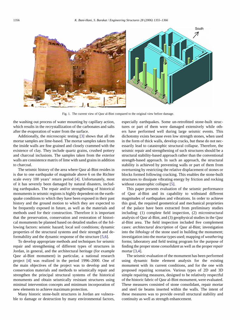
1356 K. Bani-Hani, S. Barakat / Engineering Structures 28 (2006) 1355–1366
Fig. 1. The current view of Qasr al-Bint compared to the original view before damage.
ional
omhery
eriio
sht
cluricarpad tan
tantoe f
id
mi
plrcho
tea
icasif
raor
truc-oth-hisdc-, thebe aionalturalmruilting
ncentieveties
diesralasr
ent
nt;
of
medingith3D
fulted.ortart ofand
the washing out process of water mounting by capillary actwhich results in the recrystallization of the carbonates and safter the evaporation of water from the surface.
Additionally, the microscopic testing [3] shows that all themortar samples are lime-based. The mortar samples taken frthe inside walls are fine grained and closely crammed with texistence of clay. Theyinclude quartz grains, crushed potteand charcoal inclusions. The samples taken from the extwalls are consistence matrix of lime with sand grains in additto charcoal.
The seismic history of the area where Qasr al-Bint resideis due to one earthquake of magnitude above 6 on the Ricscale every 100 years’ return period [4]. Unfortunately, mostof it has severely been damaged by natural disasters, ining earthquakes. The repair and/or strengthening of histomonuments in seismic regions is highly dependent on the equake conditions to which they have been exposed in theirhistory and the ground motion to which they are expectebe frequently exposed in future, as well as the materialsmethods used for their construction. Therefore it is importhat the preservation, conservation and restoration of hiscal monuments be planned based on detailed studies of thlowing factors: seismic hazard; local soil conditions; dynamproperties of the structural systems and their strength andformability and thedynamic response of the structure [5,6].
To develop appropriate methods and techniques for seisrepair and strengthening of different types of structuresJordan, in general, and the architectural heritage (for examQasr al-Bint monument) in particular, a national reseaproject [4] was realized in the period 1996–2000. Onethe main objectives of the project was to develop andconservation materials and methods to seismically repairstrengthen the principal structural systems of the histormonuments and obtain seismically resistant structures uminimal intervention conceptsand minimum incorporation onew elements to achieve maximum protection.
Many historic stone-built structures in Jordan are vulneble to damage or destruction by many environmental fact
,ts
orn
iner
d-alth-stodt
ri-ol-ce-
icne
fstndl
ng
-s,
especially earthquakes. Some un-retrofitted stone-built stures or part of them were damaged extensively whileers have performed well during large seismic events. Tdichotomy exists because even low strength stones, when usein the form of thick walls, develop cracks, but these do not neessarily lead to catastrophic structural collapse. Thereforeseismic repair and strengthening of such structures shouldstructural stability-based approach rather than the conventstrength-based approach. In such an approach, the strucstability is achieved by preventing walls or part of them frooverturning by restricting the relative displacement of stones oblocks formed following cracking. This enables the stone-bstructures to dissipate vibrating energy by friction and rockwithout catastrophic collapse [5].
This paper presents evaluation of the seismic performaof Qasr al-Bint and its capability to withstand differemagnitudes of earthquakes and vibrations. In order to achthis goal, the required geometrical and mechanical proprieof the palace have been extracted from preliminary stuincluding: (1) complete field inspection, (2) microstructuanalysis of Qasr al-Bint, and (3) geophysical studies in the Qal-Bint area. The field inspection included five complemcases:architectural description of Qasr al-Bint; investigationinto thelithology of the stone used in building the monumeinvestigation into the mortar types used; mapping ofweatheringforms; laboratory and field testing program for the purposefinding the proper stoneconsolidant as well as the properrepairmortar [3,4].
The seismic evaluation of the monument has been perforusing dynamic finite element analysis for the existmonument with its current conditions, and for the one wproposed repairing scenarios. Various types of 2D andsimple repairing measures, designed to be relatively respectof the historic fabric of Qasr al-Bint monument, were evaluaThese measures consisted of stone consolidant, repair mand steel tie beams inserted within the walls. The intenthese measures was to provide overall structural stabilitycontinuity as well as strength enhancement.
K. Bani-Hani, S. Barakat / Engineering Structures 28 (2006) 1355–1366 1357
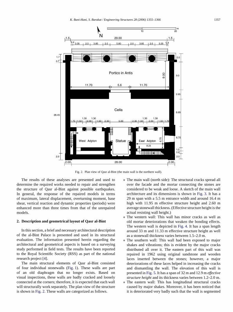
Fig. 2. Plan view of Qasr al-Bint (the main wall is the northern wall).
edthe
kesrmeerire
uratheeyin
na
tedtonseware
allareall
4 mmthe
ascts.
ell
jorkssdenajorsis
m.cksthatd
The results of these analyses are presented and usdetermine the required works needed to repair and strengthe structure of Qasr al-Bint against possible earthquaIn general, the response of the repaired models in teof maximum, lateral displacement, overturning moment, basshear, vertical reaction and dynamic properties (periods) wenhanced more than three times from that of the unrepamodels.
2. Description and geometrical layout of Qasr al-Bint
In this section, a brief and necessary architectural descriptionof the al-Bint Palace is presented and used in its structevaluation. The information presented herein regardingarchitectural and geometrical aspects is based on a survstudy performed in field tests. The results have beenreportedto the Royal Scientific Society (RSS) as part of the natioresearch project [4].
The main structural elements of Qasr al-Bint consisof four individual stonewalls (Fig. 1). These walls are parof an old diaphragm that no longer exists. Basedvisual inspections, these walls are badly cracked and looconnected at the corners; therefore, it is expected that eachwill structurally work separately. The plan view of the structuis shown inFig. 2. These walls are categorized as follows.
ton.s
ed
l
g
l
lyll
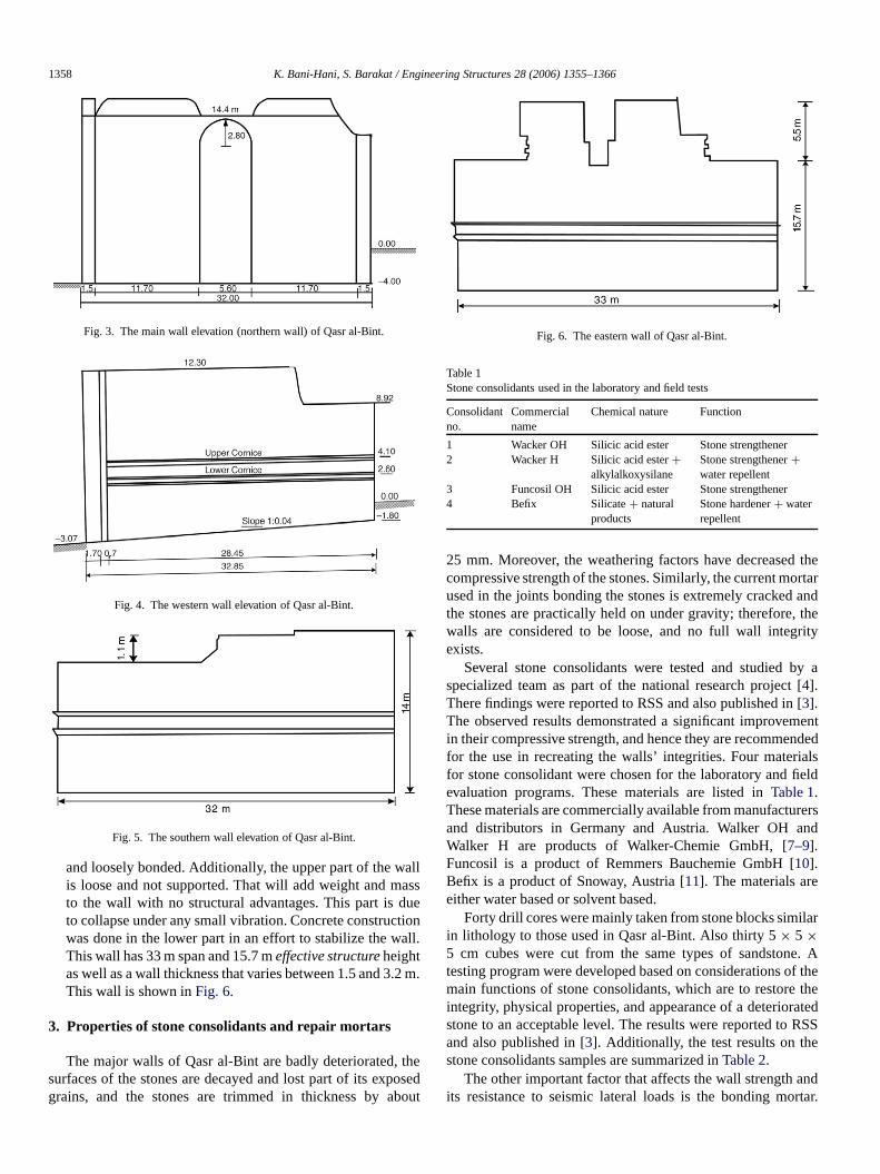
∗ The main wall (north side): The structural cracks spreadover the facade and the mortar connecting the stonesconsidered to be weak and loose. A sketch of the main warchitecture and its dimensions is shown inFig. 3. It has a29 m span with a 5.5 m entrance width and around 16.high with 11.95 m effective structure height and 2.60average stonewall thickness. (Effective structure height isactual resisting wall height.)
∗ The western wall: This wall has minor cracks as wellold mortar deteriorations that weaken the bonding effeThe western wall is depicted inFig. 4. It has a span lengtharound 33 m and 11.33 m effective structure height as was a stonewall thickness varies between 1.5–2.0 m.
∗ The southern wall: This wall had been exposed to mashakes and vibrations; this is evident by the major cracdistributed all over it. The eastern part of this wall warepaired in 1962 using original sandstone and woolaces inserted between the stones; however, a mdeteriorations of these laces helped in increasing the crackand dismantling the wall. The elevation of this wallpresented inFig. 5. It has a span of 32 m and 12.9 meffectivestructure height and its thickness varies between 1.2–2.0
∗ The eastern wall: This has longitudinal structural cracaused by major shakes. Moreover, it has been noticedit is deteriorated very badly such that the wall is segmente
1358 K. Bani-Hani, S. Barakat / Engineering Structures 28 (2006) 1355–1366
allasue
tioll.
2 m
theoso
thertarandtheity
y a[[
mentndedls
field
rersnd
lar
. Athethe
atedRSS
andrtar.
Fig. 3. The main wall elevation (northern wall) of Qasr al-Bint.
Fig. 4. The western wall elevation of Qasr al-Bint.
Fig. 5. The southern wall elevation of Qasr al-Bint.
and loosely bonded. Additionally, the upper part of the wis loose and not supported. That will add weight and mto the wall with no structural advantages. This part is dto collapse under any small vibration. Concrete construcwas done in the lower part in an effort to stabilize the waThis wall has 33 m span and 15.7 meffective structure heightas well as a wall thickness that varies between 1.5 and 3.This wall is shown inFig. 6.
3. Properties of stone consolidants and repair mortars
The major walls of Qasr al-Bint are badly deteriorated,surfaces of the stones are decayed and lost part of its expgrains, and the stones are trimmed in thickness by ab
s
n
.
edut
Fig. 6. The eastern wall of Qasr al-Bint.
Table 1Stone consolidants used in the laboratory and field tests
Consolidantno.
Commercialname
Chemical nature Function
1 Wacker OH Silicic acid ester Stone strengthener2 Wacker H Silicic acid ester+
alkylalkoxysilaneStone strengthener+water repellent
3 Funcosil OH Silicic acid ester Stone strengthener4 Befix Silicate + natural
productsStone hardener+ waterrepellent
25 mm. Moreover, the weathering factors have decreasedcompressive strength of the stones. Similarly, the current moused in the joints bonding the stones is extremely crackedthe stones are practically held on under gravity; therefore,walls are considered to be loose, and no full wall integrexists.
Several stone consolidants were tested and studied bspecialized team as part of the national research project4].There findings were reported to RSS and also published in3].The observed results demonstrated a significant improvein their compressive strength, and hence they are recommefor the use in recreating the walls’ integrities. Four materiafor stone consolidant were chosen for the laboratory andevaluation programs. These materials are listed inTable 1.These materials are commercially available from manufactuand distributors in Germany and Austria. Walker OH aWalker H are products of Walker-Chemie GmbH, [7–9].Funcosil is a product of Remmers Bauchemie GmbH [10].Befix is a product of Snoway, Austria [11]. The materials areeither water based or solvent based.
Forty drill cores were mainly taken from stone blocks simiin lithology to those used in Qasr al-Bint. Also thirty 5× 5 ×5 cm cubes were cut from the same types of sandstonetesting program weredeveloped based on considerations ofmain functions of stone consolidants, which are to restoreintegrity, physical properties, and appearance of a deteriorstone to an acceptable level. The results were reported toand also published in [3]. Additionally, thetest results on thestone consolidants samples are summarized inTable 2.
The other important factor that affects the wall strengthits resistance to seismic lateral loads is the bonding mo
K. Bani-Hani, S. Barakat / Engineering Structures 28 (2006) 1355–1366 1359
andoure
ntal-arsurenicwittartaresx
catesea
anrnTh
oorture
a
of
allgm
aed
fered
d inniteeose
idesncethetheturalelysised
iallyosen
ondare
atedhownoil
four
Table 2The compressive strength of the tested stone consolidant materials [4]
Sample Compressivestrength (MPa)
Percentage increasein compressivestrength
Untreated 16.78 00.0Treated with Wacker H 30.23 80.0Treated with Wacker OH 28.37 69.0Treated with Funcosil OH 27.68 64.9Treated with Befix 1:1 24.14 43.9Treated with Befix 1:3 25.22 50.3Treated with Befix 1:6 30.22 80.0
Table 3The mechanical strengths of the repairing mortars [3,4]
Mortar Compressivestrength(MPa)
Flexuralstrength(MPa)
Elastic modulus(E) (MPa)
RepairLime mortar 16.6 2.8 8,400RepairNamex mortar 28.2 5.8 12,300RepairFuncosil mortar 17.4 3.2 5,740Old Lime mortar 5.6 0.20 7,700Qasr al-Bint Sandstone 25.2 3.89 10,760
As stated above, the current mortar has lost its integrityneeds to be repaired or replacedwhere necessary. The applierepair mortar should not be stronger than the stones and shnot be excessively stronger than the original mortar. Thtypes of repairing mortars aresuggested, taking into accouthe properties of the old mortar used in bonding QasrBint stonewalls. The performance efficiency of the mortwas evaluated by a series of standardized testing proceddesigned to measure the physical, chemical and mechaproperties of these mortars and their bonding behaviorsandstone samples from Qasr al-Bint. The first of these moris aFuncosil restoration mortar, which is a ready-made morof cementitious raw materials with some mineral additivThe second isNamex mortar, which is composed of compleorganic polymers with silicate chemically reactive groups inaqueous solution. The reactive groups react with the silicomponents of the cement in the form of a hydration procand build up to a homogenous, mineral phase. Namex revitself, after its chemical reaction with cement and sand toend product, as an inorganic, silicate material. The third mortais a laboratory-preparedlime mortar based on the compositioof the mortar used by the Nabateans in Qasr al-Bint.mortar is composed of hydrated lime and sand in a ratio1:4 by mass. Inclusions found in the ancient Nabateans msuchas grit and charcoals were added to the mortar mixtLaboratory tests were conducted on these bonding mortarsthe mechanical properties, which are of our concern in thisstudy, are shown inTable 3. Comprehensive characteristicsthe repair mortars are presented in Ref. [3].
4. Seismic analysis of Qasr al-Bint
The palace is consisted of old dismantled surrounding wthat lack the corner connections and hence have no diaphra
d
lde
sal
hs
.
esls
efar.
nd
s
Fig. 7. Earthquake records used in the time domain analysis.
effects (Fig. 1). Therefore, it is assumed that these walls willstructurally resistthe lateral seismic forces separately. Asresult, the evaluation of the structure will be only manifestby the seismic performance of the four major walls mentionedearlier in Section 2. These walls have different states odeterioration and damage, and their states will be considin the modeling phase.
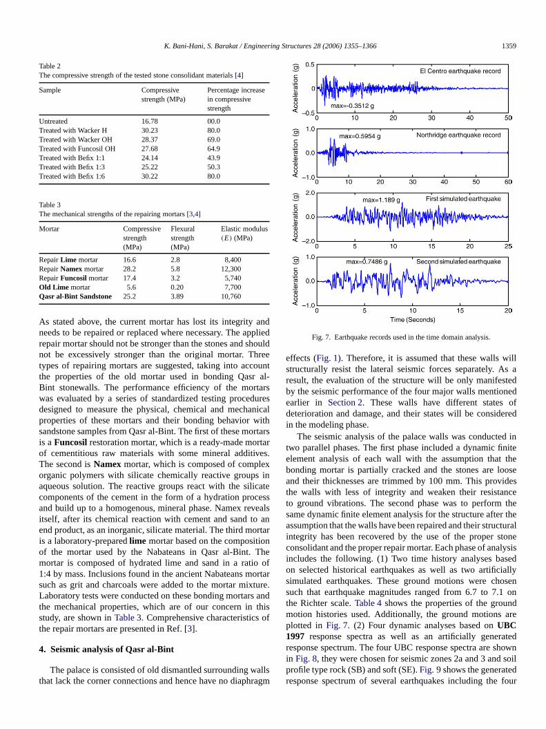
The seismic analysis of the palace walls was conductetwo parallel phases. The first phase included a dynamic fielement analysis of each wallwith the assumption that thbonding mortar is partially cracked and the stones are loand their thicknesses are trimmed by 100 mm. This provthe walls with less of integrity and weaken their resistato ground vibrations. The second phase was to performsame dynamic finite element analysis for the structure afterassumption that the walls have been repaired and their strucintegrity has been recovered by the use of the proper stonconsolidant and the proper repair mortar. Each phase of anaincludes the following. (1) Two time history analyses bason selected historical earthquakes as well as two artificsimulated earthquakes. These ground motions were chsuch that earthquake magnitudes ranged from 6.7 to 7.1the Richter scale.Table 4shows the properties of the grounmotion histories used. Additionally, the ground motionsplotted in Fig. 7. (2) Four dynamic analyses based onUBC1997 response spectra as well as an artificially generresponse spectrum. The four UBC response spectra are sin Fig. 8, they were chosen for seismic zones 2a and 3 and sprofile type rock (SB) and soft (SE).Fig. 9shows the generatedresponse spectrum of several earthquakes including the
1360 K. Bani-Hani, S. Barakat / Engineering Structures 28 (2006) 1355–1366
s
s.
cet
fin
chh
to
delding
rentsodel
mass
indare
his
ghts.m..gh,and
elndingshell
andeakthe
onewas
rial.t as
Fig. 8. 1997 Response spectra for different seismic zones and soft rockprofiles.
Fig. 9. Artificially generated response spectrum of several time historie
Table 4Properties of the time history records used in this study
Earthquake description Earthquakemagnitude
PGA (cm/s2) PGA (g)
Imperial Valley, 1940, El Centro 6.9 344.7 0.3512Northridge, 1994, Sylmar 6.7 584.39 0.5954First simulated earthquake, 10%in 50 years, Soil type soft
7.1 1167.20 1.1892
Second simulated earthquake,10% in 50 years, Soil type soft
6.9 734.751 0.7486
time history earthquakes used inTable 4. It is worthmentioningthat the purpose of this work is to estimate the performanimprovement of the seismic response of the structure due tosuggested repairing techniques.
4.1. Analysis of Qasr al-Bint walls
The Qasr al-Bint walls have been evaluated and testedseismic resistance with the finite element method (FEM) usSAP2000. Clearly,Fig. 3 shows that the main wall has twosegments thatare connected by a deteriorated 5.5 m arTherefore, in the analysis, it has been assumed that eac
oil
he
org
.of
Fig. 10. Maximum lateral horizontal displacement for the main wall duedifferent earthquakes.
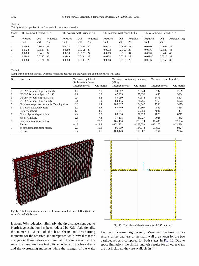
the 11.7 m span walls will work separately. The FEM moconsidered the difference in the sandstones and the bonmortar properties; hence, the model was layered with diffeshell elements and sections (seeFig. 12). The shell elementare taken to have a constant thickness of 2.6 m. The mheight is about 12 m and the additional height of the wallabove this level was assumed to be dead load and addedto the wall.Fig. 4 shows the western wall dimensions and itsgeometry. The FEM model for this wall is about 33 mlength and 11.33 m high, and therest of the height is replacein the model as weights and masses. The shell elementstaken to have thickness of 1.5–2.0 m at different places.Fig. 5shows the southern wall dimensions and its geometry. Twall has 32 min span and themodel was 12.9 m high, whilethe rest of the height is substituted as masses and weiThe FEM model has varying shell thickness of 1.2–2.0Fig. 6 shows the eastern wall dimensions and its geometryThis wall has 33 m in span and the model is 15.7 m hiwhile the rest of the height is substituted as massesweights.
Two FEM models were prepared for all walls; the first modassumed stones decayed by 100 mm as well as loose bobetween the stones, and this was achieved by using aelement thickness of 100 mm less than the measured oneby adjusting the properties of the old mortar to represent wdeteriorated material, which was achieved by decreasingmodulus of elasticity of the old mortar as given inTable 3by40%. The second model dealt with the walls when the stconsolidant was used and the cracked damaged mortarfilled and repaired using the suggested lime mortar mateThe properties of the old stones and mortar of Qasr al-Bin
K. Bani-Hani, S. Barakat / Engineering Structures 28 (2006) 1355–1366 1361
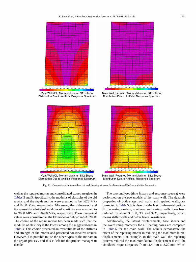
Fig. 11. Comparisons between the axialand shearing stresses for the main wall before and after the repairs.
inldMPandric00t tes
susr
ereic
es
beenich
andredelingeich
well as the repaired mortar and consolidated stones are givenTables 2and3. Specifically, the modulus of elasticity of the omortar and the repair mortar were assumed to be 4620and 8400 MPa, respectively. Moreover, the old-stones’the consolidated-stones’ modulus of elasticity was assumebe 9000 MPa and 10760 MPa, respectively. These numevalues were considered in the FE model as defined in SAP2The choice of the repair mortar has been made such thamodulus of elasticity is the lowest among the suggested onTable 3. This choice prevented an overestimate of the stiffnessand strength of the mortar and presented conservative reHowever, it is possible to use the other types of the mortarthe repair process, and this is left for the project managedecide.
adtoal0.hein
lts.into
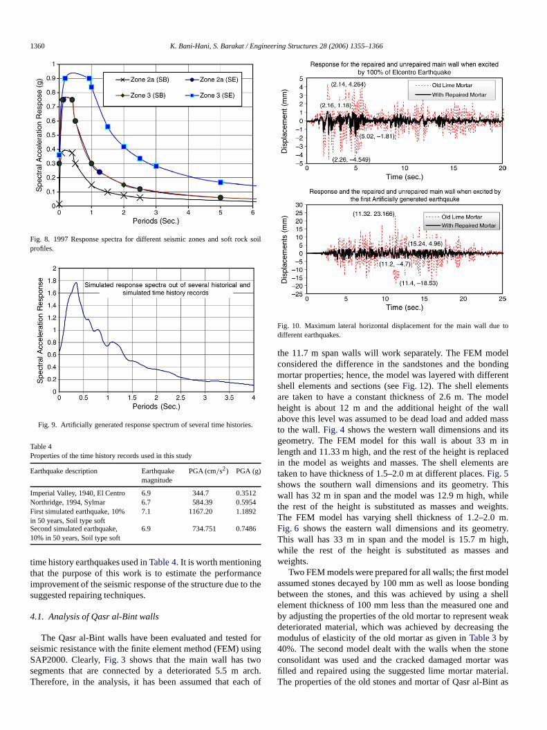
The two analyses (time history and response spectra) wperformed on the two models of the main wall. The dynamproperties of both states, old walls and repaired walls, arpresented inTable 5. It is clear that the first fundamental periodof the main, western, southern, and eastern walls havereduced by about 38, 30, 33, and 39%, respectively, whmeans stiffer walls and better lateral resistances.
Additionally, the lateral displacements, base shearsthe overturning moments for all loading cases are compain Table 6 for the main wall. The results demonstrate theffect of the repairing mortarin reducing the maximum lateradisplacements. For example, in the main wall the repairprocess reduced the maximum lateral displacement due to thsimulated response spectra from 11.4 mm to 3.29 mm, wh
1362 K. Bani-Hani, S. Barakat / Engineering Structures 28 (2006) 1355–1366
Table 5Thedynamic properties of the four walls in the strong direction
Modeno.
The main wall Period(T ) s The western wall Period(T ) s The southern wall Period(T ) s Theeastern wall Period(T ) s
Repairedwall
Oldwall
Reduction(%)
Repairedwall
Oldwall
Reduction(%)
Repairedwall
Oldwall
Reduction(%)
Repairedwall
Oldwall
Reduction (%)
1 0.0996 0.1606 38 0.0413 0.0589 30 0.0423 0.0633 33 0.0590 0.0962 392 0.0323 0.0528 39 0.0280 0.0351 20 0.0273 0.0362 25 0.0316 0.0535 413 0.0289 0.0460 37 0.0210 0.0275 24 0.0209 0.0316 34 0.0270 0.0449 404 0.0140 0.0222 37 0.0149 0.0194 23 0.0154 0.0217 29 0.01980 0.0316 375 0.0080 0.0121 34 0.0083 0.0108 23 0.0083 0.0116 28 0.0096 0.0155 38
ortar
659264324573917558
12
34
24
Table 6Comparison of the main wall dynamic responses between the old wall state and the repaired wall state
No. Loadcase Maximum tip lateraldisplacement (mm)
Maximum overturning moments(kNm)
Maximum base shear (kN)
Repaired mortar Old mortar Repaired mortar Old mortar Repaired mortar Old m
1 UBC97 Response Spectra 2a;SB 1.2 3.1 39,982 38,644 2734 22 UBC97 Response Spectra 2s;SE 2.1 6.2 67,935 77,352 4652 53 UBC97 Response Spectra 3;SB 2.4 6.2 80,050 77,372 5475 54 UBC97 Response Spectra 3;SE 2.1 6.9 69,115 81,755 4761 55 Simulated response spectra for 7 earthquakes 3.3 11.4 108,617 134,847 75016 El Centro earthquake time 1.2 4.3 60,749 57,307 4563 43
History analysis −1.8 −4.6 −41,341 −50,650 −4090 −44517 Northridge earthquake time 2.2 7.8 88,630 97,623 7823 82
History analysis −2.6 −7.8 −77,108 −89,727 −7026 −78938 First simulated time history 5.0 23.2 165,114 283,314 15,489 22,1
Record −4.7 −18.5 −171,232 −263,233 −15,175 −20,5349 Second simulated time history 2.9 10.1 95,339 114,974 9135.6 98
Record −2.7 −9.1 −100,443 −116,907 −9160 −9744
,g
t t
heal
wo
alls
Fig. 12. The finite element model for the eastern wall of Qasr al-Bint (Note thevariable shell thickness).
is about 70% reduction. Similarly, the tip displacement dueNorthridge excitation has been reduced by 72%. Additionallythe numerical values of the base shears and overturninmoments for the repaired and unrepaired walls reveal thachanges in these values are minimal. This indicates that therepairing measures have insignificant effects on the base sand the overturning moments while the strength of the w
to
he
arsls
Fig. 13. Plan view of the tie beams at 11.355 m levels.
has been increased significantly. Moreover, the time historyresults of the analysis of the main wall are shown for the tearthquakes and compared for both states inFig. 10. Due tospace limitations the similar analysis results for all other ware not included; they are available in [4].
K. Bani-Hani, S. Barakat / Engineering Structures 28 (2006) 1355–1366 1363
ortar
4
Table 7Maximum shearing and tensile stresses in mortars due to several dynamic analyses
Loadcase σ11 (MPa) σ22 (MPa) σ12 (MPa)Repaired mortar Old mortar Repaired mortar Old mortar Repaired mortar Old m
UBC97 Response Spectra 2a;SB 0.12 0.23 0.70 0.91 0.12 0.16UBC97 Response Spectra 2s;SE 0.20 0.45 1.20 1.81 0.20 0.31UBC97 Response Spectra 3;SB 0.24 0.45 1.41 1.81 0.24 0.31UBC97 Response Spectra 3;SE 0.21 0.48 1.22 1.92 0.20 0.33Simulated response spectra for 7 earthquakes 0.33 0.79 1.91 3.16 0.32 0.5El Centro earthquake time 0.18 0.31 1.08 1.24 0.15 0.23History analysis −0.18 −0.34 −1.02 −1.35 −0.19 −0.24Northridge earthquake time 0.27 0.54 1.61 2.18 0.26 0.40History analysis −0.28 −0.59 −1.51 −2.38 −0.30 −0.43First simulated time history 0.53 1.58 3.01 6.32 0.57 1.13Record −0.52 −1.70 −3.10 −6.81 −0.57 −1.22Second simulated time history 0.32 0.71 1.74 2.84 0.34 0.52Record −0.30 −0.70 −1.83 −2.81 −0.34 −0.52
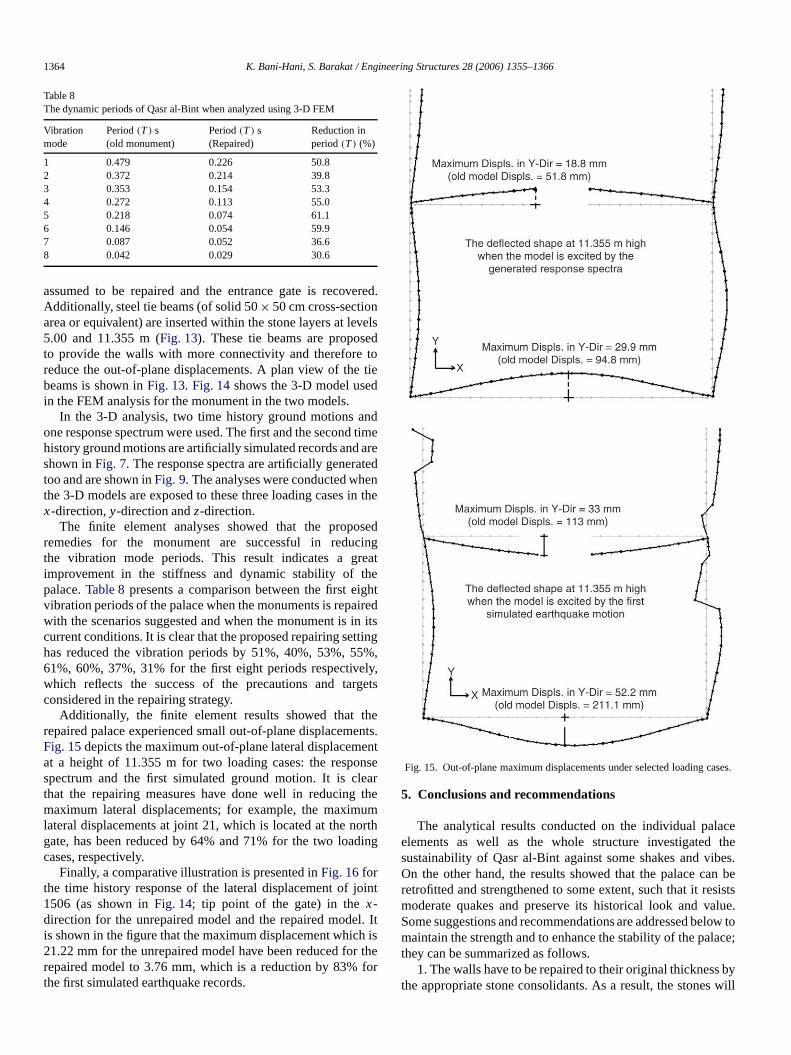
Fig. 14. Three-dimensional model of Qasr al-Bintwith strengthening connections atthe corners, steel frame, reconstructed arch and the bonding mortars.
xiaaibond
lemtraon
im
ldpa
delsentntwasrtarwasssesrtared-asthatosenthe
ts is
Moreover,Table 7presents a comparison between the aand shearing stresses in the old mortar as well as the repmortar due to the loading cases discussed earlier. Clearly,stresses have been reduced due to the repairing measures atheir values are less than the mortar compressive strength anflexural strength as given inTables 2and 3, which indicatesthat the mortar has sustained the stress demand. For exampin the main wall the repairing process reduced the maximushearing stresses,σ12, due to the simulated response specfrom 0.54 MPa to 0.32 MPa, which is about 41% reductiSimilarly, the axial stressesσ11 andσ22 due tothe simulatedresponse spectra have been reduced by 58% and 40%. Sresults are depicted inFig. 11, where the stress distribution ofthe axial and shearing stresses is compared for the main walbefore and after repairs. The same results can be concludethe other parts of the monuments; however, because of slimitations these results have been omitted in this paper.
lredth
d
,
,.
ilar
force
4.2. Analysis of three-dimensional FE model of Qasr al-Bint
The monument is modeled as 3-D finite element mo(Fig. 14) to study and evaluate the out-of-plane displacementas well as the potentials of reconstructing the monumintegrities with particular settings. Two 3-D finite elememodels were studied and evaluated. The first modelmodeled after the in situ study for the stone and the moconditions and is referred to as the old model. This modeldeveloped using 1590 shell elements with variable thicknereflecting the wall thicknesses variations and the stone/moproperties as instituted in field: loose mortar and deteriorattrimmed stones (Fig. 12). The second model, referred tothe repaired model, was designed with the assumptionthe walls are smeared together at the corners by the chstone consolidant as well as the repair mortar. Moreover,deteriorated arch that connects the main wall segmen
1364 K. Bani-Hani, S. Barakat / Engineering Structures 28 (2006) 1355–1366
.
vedto
ndt
arteen
t
seint
heghiri
tin%ly
ge
he.tnath
di
in
l.it
fo
ses.
acethe
bes.esistslue.
low tolace;
bywill
Table 8Thedynamic periods of Qasr al-Bint when analyzed using 3-D FEM
Vibrationmode
Period(T ) s(old monument)
Period(T ) s(Repaired)
Reduction inperiod(T ) (%)
1 0.479 0.226 50.82 0.372 0.214 39.83 0.353 0.154 53.34 0.272 0.113 55.05 0.218 0.074 61.16 0.146 0.054 59.97 0.087 0.052 36.68 0.042 0.029 30.6
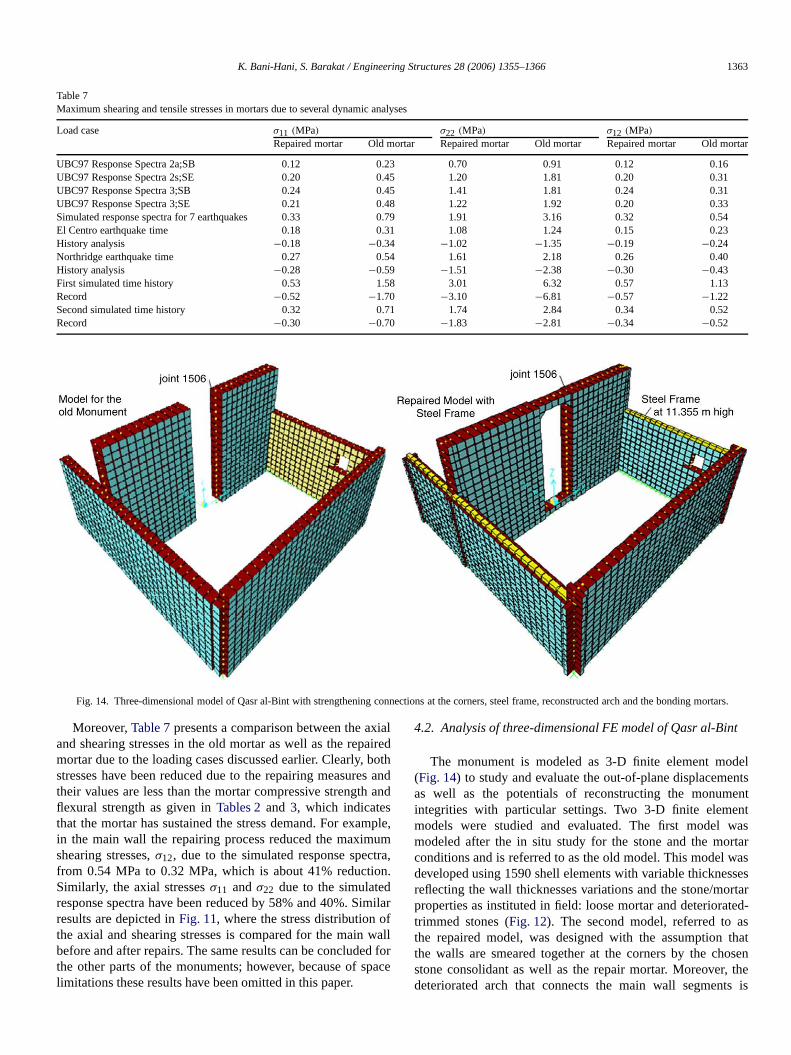
assumed to be repaired and the entrance gate is recoveredAdditionally, steel tie beams (of solid 50× 50 cm cross-sectionarea or equivalent) are inserted within the stone layers at le5.00 and 11.355 m (Fig. 13). These tie beams are proposeto provide the walls with more connectivity and thereforereduce the out-of-plane displacements. A plan view of the tiebeams is shown inFig. 13. Fig. 14 shows the3-D model usedin the FEM analysis for the monument in the two models.
In the 3-D analysis, two time history ground motions aone response spectrum were used. The first and the secondhistory ground motions are artificially simulated records andshown inFig. 7. The response spectra are artificially generatoo and are shown inFig. 9. The analyses were conducted whthe 3-D models are exposed to these three loading cases inx-direction,y-direction andz-direction.
The finite element analyses showed that the proporemedies for the monument are successful in reducthe vibration mode periods. This result indicates a greaimprovement in the stiffness and dynamic stability of tpalace.Table 8presents a comparison between the first eivibration periods of the palace when the monuments is repawith the scenarios suggested and when the monument is incurrent conditions. It is clear that the proposed repairing sethas reduced the vibration periods by 51%, 40%, 53%, 5561%, 60%, 37%, 31% for the first eight periods respectivewhich reflects the success of the precautions and tarconsidered in the repairing strategy.
Additionally, the finite element results showed that trepaired palace experienced small out-of-plane displacementsFig. 15depicts the maximum out-of-plane lateral displacemenat a height of 11.355 m for two loading cases: the respospectrum and the first simulated ground motion. It is clethat the repairing measures have done well in reducingmaximum lateral displacements; for example, the maximumlateral displacements at joint21, which is located at the northgate, has been reduced by 64% and 71% for the two loacases, respectively.
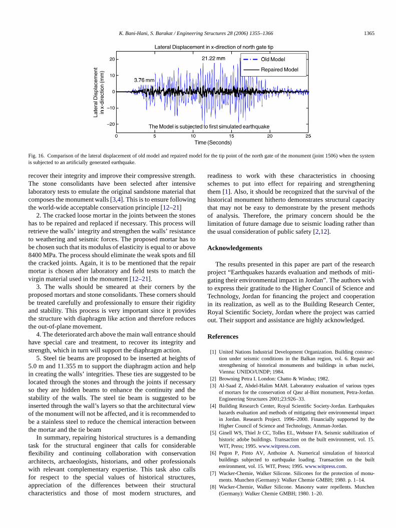
Finally, a comparative illustration is presented inFig. 16 forthe time history response of the lateral displacement of jo1506 (as shown inFig. 14; tip point of the gate) in thex-direction for the unrepaired model and the repaired modeis shown in the figure that the maximum displacement which21.22 mm for the unrepaired model have been reduced forrepaired model to 3.76 mm, which is a reduction by 83%the first simulated earthquake records.
ls
imeed
he
dg
tedtsg,,ts
sere
ng
t
Itsher
Fig. 15. Out-of-plane maximum displacements under selected loading ca
5. Conclusions and recommendations
The analytical results conducted on the individual palelements as well as the whole structure investigatedsustainability of Qasr al-Bint against some shakes and viOn the other hand, the resultsshowed that the palace can bretrofitted and strengthened to some extent, such that it remoderate quakes and preserve its historical look and vaSome suggestions and recommendations are addressed bemaintain the strength and to enhance the stability of the pathey can be summarized as follows.
1. The walls have to be repaired to their original thicknessthe appropriate stone consolidants. As a result, the stones
K. Bani-Hani, S. Barakat / Engineering Structures 28 (2006) 1355–1366 1365
Fig. 16. Comparison of the lateral displacement of old model and repaired model for the tip point of the north gate of the monument (joint 1506) when the systemis subjected to an artificially generated earthquake.
gtea
ss wncsod
pat
thho
dec
oua
tsheoyheb
iewd
glennal,
ura
ingg
hecityhodsthean
architi-
ishnd
tionter,d.
-and,
dan.
spact
the
of15.
luilt
nu-
hen
recover their integrity and improve their compressive strenThe stone consolidants have been selected after intensivlaboratory tests to emulate the original sandstone material thcomposes the monument walls [3,4]. This is to ensure followingthe world-wide acceptable conservation principle [12–21]
2. The cracked loose mortar in the joints between the stonehas to be repaired and replaced if necessary. This procesretrieve the walls’ integrity and strengthen the walls’ resistato weathering and seismic forces. The proposed mortar habe chosen such that its modulus of elasticity is equal to or ab8400 MPa. The process should eliminate the weak spots anthe cracked joints. Again, it is to be mentioned that the remortar is chosen after laboratory and field tests to matchvirgin material used in the monument [12–21].
3. The walls should be smeared at their corners byproposed mortars and stone consolidants. These corners sbe treated carefully and professionally to ensure their rigidityand stability. This process is very important since it provithe structure with diaphragm like action and therefore redutheout-of-plane movement.
4. The deteriorated arch above the main wall entrance shhave special care and treatment, to recover its integritystrength, which in turn will support the diaphragm action.
5. Steel tie beams are proposed to be inserted at heigh5.0 m and 11.355 m to support the diaphragm action andin creating the walls’ integrities. These ties are suggested tlocated through the stones andthrough the joints if necessarso they are hidden beams to enhance the continuity and tstability of the walls. The steel tie beam is suggested toinserted through the wall’s layers so that the architectural vof the monument will not be affected, and it is recommendebe a stainless steel to reduce the chemical interaction betweenthe mortar and the tie beam
In summary, repairing historical structures is a demandintask for the structural engineer that calls for considerabflexibility and continuing collaboration with conservatioarchitects, archaeologists, historians, and other professiowith relevant complementary expertise. This task also cfor respect to the special values of historical structuresappreciation of the differences between their structcharacteristics and those of most modern structures,
h.
t
illetovefillir
he
euld
ses
ldnd
oflpbe
e
to
alsls
alnd
readiness to work with these characteristics in choosschemes toput into effect for repairing and strengtheninthem [1]. Also, it should be recognized that the survival of thistorical monument hitherto demonstrates structural capathat may not be easy to demonstrate by the present metof analysis. Therefore, the primary concern should belimitation of future damage due to seismic loading rather ththe usual consideration of public safety [2,12].
Acknowledgements
The results presented in this paper are part of the reseproject “Earthquakes hazards evaluation and methods of mgating their environmental impact in Jordan”. The authors wto express their gratitude to the Higher Council of Science aTechnology, Jordan for financing the project and cooperain its realization, as well as to the Building Research CenRoyal Scientific Society, Jordan where the project was carrieout. Their support and assistance are highly acknowledged
References
[1] United Nations Industrial Development Organization. Building construction under seismic conditions in the Balkan region, vol. 6. Repairstrengthening of historical monuments and buildings in urban nucleiVienna: UNIDO/UNDP; 1984.
[2] Browning Petra I. London: Chatto & Windus; 1982.[3] Al-Saad Z, Abdel-Halim MAH. Laboratory evaluation of various types
of mortars for the conservation of Qasr al-Bint monument, Petra-JorEngineering Structures 2001;23:926–33.
[4] Building Research Center, Royal Scientific Society-Jordan. Earthquakehazards evaluation and methods of mitigating their environmental imin Jordan. Research Project. 1996–2000. Financially supported byHigher Council of Science andTechnology, Amman-Jordan.
[5] Ginell WS, Thiel Jr CC, Tolles EL, Webster FA. Seismic stabilizationhistoric adobe buildings. Transaction on the built environment, vol.WIT, Press; 1995.www.witpress.com.
[6] Pegon P, Pinto AV, Anthoine A. Numerical simulation of historicabuildings subjected to earthquake loading. Transaction on the benvironment, vol. 15. WIT, Press; 1995.www.witpress.com.
[7] Wacker-Chemie, Walker Silicone. Silicones for the protection of moments. Munchen (Germany): Walker Chemie GMBH; 1980. p. 1–14.
[8] Wacker-Chemie, Walker Silicone. Masonry water repellents. Munc(Germany): Walker Chemie GMBH; 1980. 1–20.
1366 K. Bani-Hani, S. Barakat / Engineering Structures 28 (2006) 1355–1366
ste
ma
c-ionstri
rth
e.d
er-e;
t Dpts
ric
tion” aten
ing
on:n
uesg and
ofject.
[9] Wacker-Chemie. Stone strengtheners on the basis of silicic acid eMunchen (Germany): Walker Chemie GMBH; 1981. 1–6.
[10] Remmers funcosil facade protection and restoration systems. GerRemmers Bauchemie GMBH; 1995.
[11] Sanotec Austria. Innovation, research and development for the protetion of the environment, special products for buildings, constructpreservation and treatment. Sanotec Austria technical report. Au1995.
[12] Feilden BM. Conservation of historic buildings. London: ButterwoScientific; 1982.
[13] Moran T. Strengthening earthquake-damaged structures. In: Thassessment and mitigation of earthquake risk. UNESCO-Paris; 1978
[14] Dowrick DJ. Earthquake resistant design. In: A manual for engineers anarchitects. London: Wiley; 1977. p. 255.
[15] UNESCO. The cultural heritage and natural disasters. World cultural hitage information bulletin, vol. 15. Paris: Division of Cultural Heritag1980.
[16] Brosens K, Ignoul S, Schueremans L, Van Balen K, Van GemerStevens P. Park Abbey at Heverlee, Belgium — old and new conce
rs.
ny:
,a;
,
in the restoration of a farm wing, Florence: Conservation of HistoWooden Structures; 2005. p. 204–12.
[17] Ignoul S, Schueremans L, Van Gemert D, Van Meer H. Restoraand rehabilitation of the 17th century abbey barn “TiendenschuurHerckenrode, Belgium, Florence: Conservation of Historic WoodStructures; 2005. p. 221–26.
[18] Schueremans L, Van Gemert D. Assessing the safety of historicalmasonry structures. In: 8th international conference on modern buildmaterials, structures and techniques. 2004.
[19] Van Gemert D, Ignoul S, Van Rickstal F, Toumbakari E-E. Evolutiof structural consolidation and strengthening of masonry in Belgiumhistorical overview and case studies. International Journal for Restoratioof Buildings and Monuments 2003.
[20] Ann G. The legal and ethical consideration of mural conservation: issand debates. Paper presented at the Getty symposium Mural PaintinConservation in the Americas. 2003.
[21] Tolles EL, Edna EK, Frederick AW, William SG. Seismic stabilizationhistoric adobe structures: Final report of the Getty seismic adobe proLos Angeles: The Getty Conservation Institute; 2000.