Embed Size (px)
Citation preview
CONTENTS
DESCRIPTION
1 DESIGN DATA
2 CALCULATIONS FOR MINIMUM SHELL THICKNESS
3 BOTTOM PLATE DESIGN
4 INTERMEDIATE WIND GIRDER
5 VERIFICATION OF UNSTIFFENED SHELL
6 DESIGN OF ROOF PLATE
6.1 COMPRESSION AREA VERIFICATION AGAINST EXTERNAL PRESSURE
6.2 COMPRESSION AREA VERIFICATION AGAINST INTERNAL PRESSURE
7 TANK VERIFICATION AS PER APPENDIX F
8 ROOF THICKNESS AND COMPRESSION AREA VERIFICATION AS PER API 620
8.1 DESIGN DATA
8.2 ROOF DESIGN
8.3 COMPRESSION AREA DESIGN
9 STABILITY OF TANK AGAINST WIND LOADS
9.1)RESISTANCE TO SLIDING
10 STABILITY OF TANK AGAINST SEISMIC LOADS
10.1 RESISTANCE TO OVER TURNING
10.2 SHELL COMPRESSION FOR UNANCHORED TANKS
10.3 SHELL COMPRESSION FOR ANCHORED TANKS
11 ANCHORAGE FOR UPLIFT LOAD CASES
12 ANCHOR CHAIR CALCULATION
13 DESIGN OF INTERNAL FLAOTING ROOF (BOUYANCY CALCULATIONS)
14 FOUNDATION LOADING DATA
15 EVALUATION OF EXTERNAL LOADS ON TANK SHELL OPENINGS
AS PER P.3 OF API 650, ADD. 4, 2005
16 VRV AND VENTING CALCULATIONS (PENDING)
SR. NO.

Design Code : API 650, 10th Edition, ADD. 4, 2005, Appendices F, S & V
Client's Specs. : PIP VESTA 002
Item No. : TK-59301
Description : Acetone Storage Tank
Material : A 240 Type 304L
Density of Contents = 791
Specific Gravity of Contents G = 0.791
Material's Yield Strength ( At Design Temp.) = 148 MPa ( As Per Table S-5)
Design Temperature T = 90
Operating Temperature T = 35
Design Internal Pressure = 4.00 kPa = 20.32 in. of content
Design External Pressure = 0.90 kPa = 4.57 in. of content
High Liquid Level = 16.75 m
Design Liquid Level = 17.587 m
Allowable Design Stress ( At Design Temp.) = 132 MPa (As Per Table S-2)
Allowable Hydrostatic Stress at Test Temp. = 155 MPa ( As Per Table S-2)
Corrosion Allowance
Bottom = 0.00 mm
Shell = 0.00 mm
Roof = 0.00 mm
Structure = 0.00 mm
Slope of Tank Roof = 9.46 degree
Outside Dia. of Tank = 20.930 m
Inside Dia. of Tank = 20.900 m
Nominal Tank Dia.= Di + Shell Thk. = D = 20.915 m
Height of Shell H = 18.00 m
Weight of Top Compression Ring = 84.72 kN
Weight of Accessories on Shell (Stair, Ins., Clips & Nozzles etc.) = 100.00 kN (Assumed)
Weight of Roof Attachments (Platform, Ins., Handrail & Nozzles etc.) = 50.00 kN (Assumed)
Design Wind Velocity V = 155 kph
Modulus of Elasticity @ Design Temp. E = 189000 MPa (As Per Table S-6)
Yield Strength of Steel Structure (Ladder, platform, etc.) = 250.00 MPa
Live Load on Roof = 1.20 kPa (PIP VESTA002, 3.2.D)
The required shell plates thickness shall be greater of the values computed by following formulas.
The minimum thickness of shell plate as per App. S, Clause S.3.2, shall be computed using following formula.
Sd*(E)
(St)* E
G = Specific gravity of fluid to be stored = 0.791
D = Nominal dia. of tank = 20.915 m
= 17.587 m
CA = Corrosion allowance. = 0.00 mm
= 132.00 MPa
= 155.00 MPa
E = Weld Joint Efficiency = 0.85
1) DESIGN DATA
Dc kg./m3
Fym
oC
oC
Pi
Pe
Hl
*HL1
Sd
St
Do
Di
Wc
Wsa
Wra
Fy
Lr
*Including Static Head Due To Internal Pressure & Liquid Head due to rise of liquid in Rim Portion (in punctured condition).
2) CALCULATIONS FOR MIN. SHELL THICKNESS
Design Shell Thickness td = 4.9D (H L - 0.3)G + CA
Hydrostatic Test Thickness tt = 4.9D (H L - 0.3)
td = Design shell thickness, mm
tt = Hydrostatic test shell thickness, mm
HL1 = Design liquid level
Sd = Allowable stress for design condition
St = Allowable stress for hydrostatic condition
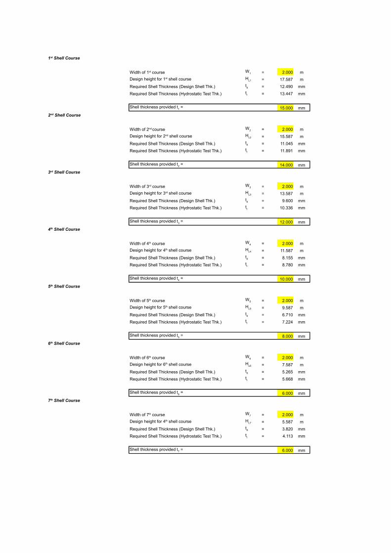
= 2.000 m
= 17.587 m
Required Shell Thickness (Design Shell Thk.) = 12.490 mm
Required Shell Thickness (Hydrostatic Test Thk.) = 13.447 mm
15.000 mm
= 2.000 m
= 15.587 m
Required Shell Thickness (Design Shell Thk.) = 11.045 mm
Required Shell Thickness (Hydrostatic Test Thk.) = 11.891 mm
14.000 mm
= 2.000 m
= 13.587 m
Required Shell Thickness (Design Shell Thk.) = 9.600 mm
Required Shell Thickness (Hydrostatic Test Thk.) = 10.336 mm
12.000 mm
= 2.000 m
= 11.587 m
Required Shell Thickness (Design Shell Thk.) = 8.155 mm
Required Shell Thickness (Hydrostatic Test Thk.) = 8.780 mm
10.000 mm
= 2.000 m
= 9.587 m
Required Shell Thickness (Design Shell Thk.) = 6.710 mm
Required Shell Thickness (Hydrostatic Test Thk.) = 7.224 mm
8.000 mm
= 2.000 m
= 7.587 m
Required Shell Thickness (Design Shell Thk.) = 5.265 mm
Required Shell Thickness (Hydrostatic Test Thk.) = 5.668 mm
6.000 mm
= 2.000 m
= 5.587 m
Required Shell Thickness (Design Shell Thk.) = 3.820 mm
Required Shell Thickness (Hydrostatic Test Thk.) = 4.113 mm
6.000 mm
1st Shell Course
Width of 1st course W1
Design height for 1st shell course HL1
td
tt
Shell thickness provided t1 =
2nd Shell Course
Width of 2nd course W2
Design height for 2nd shell course HL2
td
tt
Shell thickness provided t2 =
3rd Shell Course
Width of 3rd course W3
Design height for 3rd shell course HL3
td
tt
Shell thickness provided t3 =
4th Shell Course
Width of 4th course W4
Design height for 4th shell course HL4
td
tt
Shell thickness provided t4 =
5th Shell Course
Width of 5th course W5
Design height for 5th shell course HL5
td
tt
Shell thickness provided t5 =
6th Shell Course
Width of 6th course W6
Design height for 6th shell course HL6
td
tt
Shell thickness provided t6 =
7th Shell Course
Width of 7th course W7
Design height for 4th shell course HL7
td
tt
Shell thickness provided t7 =
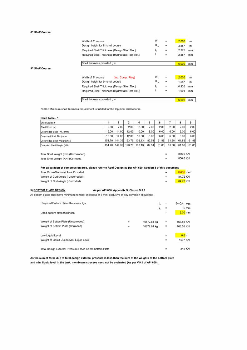
= 2.000 m
= 3.587 m
Required Shell Thickness (Design Shell Thk.) = 2.375 mm
Required Shell Thickness (Hydrostatic Test Thk.) = 2.557 mm
6.000 mm
(Inc. Comp. Ring) = 2.000 m
= 1.587 m
Required Shell Thickness (Design Shell Thk.) = 0.930 mm
Required Shell Thickness (Hydrostatic Test Thk.) = 1.001 mm
6.000 mm
NOTE: Minimum shell thickness requirement is fulfilled for the top most shell course.
Shell Table - 1
Shell Course # 1 2 3 4 5 6 7 8 9
Shell Width (m) 2.00 2.00 2.00 2.00 2.00 2.00 2.00 2.00 2.00
Uncorroded Shell Thk. (mm) 15.00 14.00 12.00 10.00 8.00 6.00 6.00 6.00 6.00
Corrroded Shell Thk.(mm) 15.00 14.00 12.00 10.00 8.00 6.00 6.00 6.00 6.00
Uncorroded Shell Weight (KN) 154.70 144.39 123.76 103.13 82.51 61.88 61.88 61.88 61.88
Corroded Shell Weight (KN) 154.70 144.39 123.76 103.13 82.51 61.88 61.88 61.88 61.88
Total Shell Weight (KN) (Uncorroded) = 856.0 KN
Total Shell Weight (KN) (Corroded) = 856.0 KN
For calculation of compression area, please refer to Roof Design as per API 620, Section 8 of this document.
Total Cross-Sectional Area Provided = 16430
Weight of Curb Angle ( Uncorroded) = 84.72 KN
Weight of Curb Angle ( Corroded) = 84.72 KN
As per API 650, Appendix S, Clause S.3.1
All bottom plates shall have minimum nominal thickness of 5 mm, exclusive of any corrosion allowance.
= 5+ CA mm
= 5 mm
Used bottom plate thickness = 6.00 mm
Weight of BottomPlate (Uncorroded) = 16672.84 kg = 163.56 KN
Weight of Bottom Plate (Corroded) = 16672.84 kg = 163.56 KN
Low Liquid Level = 0.6 m
Weight of Liquid Due to Min. Liquid Level = 1597 KN
Total Design External Pressure Froce on the bottom Plate = 313 KN
As the sum of force due to total design external pressure is less than the sum of the weights of the bottom plate
and min. liquid level in the tank, membrane stresses need not be evaluated (As per V.9.1 of API 650).
8th Shell Course
Width of 8th course W8
Design height for 8th shell course HL8
td
tt
Shell thickness provided t8 =
9th Shell Course
Width of 9th course W9
Design height for 9th shell course HL9
td
tt
Shell thickness provided t9 =
mm2
3) BOTTOM PLATE DESIGN
Required Bottom Plate Thickness tb = tb
tb
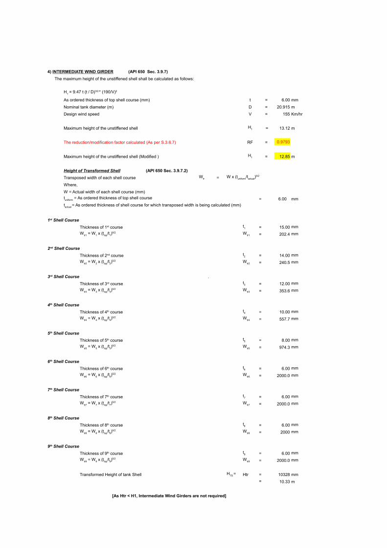
(API 650 Sec. 3.9.7)
The maximum height of the unstiffened shell shall be calculated as follows:
As ordered thickness of top shell course (mm) t = 6.00 mm
Nominal tank diameter (m) D = 20.915 m
Design wind speed V = 155 Km/hr
Maximum height of the unstiffened shell = 13.12 m
The reduction/modification factor calculated (As per S.3.6.7) RF = 0.9793
Maximum height of the unstiffened shell (Modified ) = 12.85 m
Height of Transformed Shell (API 650 Sec. 3.9.7.2)
Transposed width of each shell course =
Where,
W = Actual width of each shell course (mm)
= 6.00 mm
= 15.00 mm
= 202.4 mm
= 14.00 mm
= 240.5 mm
.
= 12.00 mm
= 353.6 mm
= 10.00 mm
= 557.7 mm
= 8.00 mm
= 974.3 mm
= 6.00 mm
= 2000.0 mm
= 6.00 mm
= 2000.0 mm
= 6.00 mm
= 2000 mm
= 6.00 mm
= 2000.0 mm
Transformed Height of tank Shell Htr = 10328 mm
= 10.33 m
[As Htr < H1, Intermediate Wind Girders are not required]
4) INTERMEDIATE WIND GIRDER
H1 = 9.47 t (t / D)3/2 * (190/V)2
H1
H1
Wtr W x (tuniform/tactual)5/2
tuniform
= As ordered thickness of top shell course
tactual = As ordered thickness of shell course for which transposed width is being calculated (mm)
1st Shell Course
Thickness of 1st course t1
Wtr1 = W1 x (ttop/t1)5/2 Wtr1
2nd Shell Course
Thickness of 2nd course t2
Wtr2 = W2 x (ttop/t2)5/2 Wtr2
3rd Shell Course
Thickness of 3rd course t3
Wtr3 = W3 x (ttop/t3)5/2 Wtr3
4th Shell Course
Thickness of 4th course t4
Wtr4 = W4 x (ttop/t4)5/2 Wtr4
5th Shell Course
Thickness of 5th course t5
Wtr5
= W5 x (t
top/t
5)5/2 W
tr5
6th Shell Course
Thickness of 6th course t6
Wtr6
= W6 x (t
top/t
6)5/2 W
tr6
7th Shell Course
Thickness of 7th course t7
Wtr7 = W7 x (ttop/t7)5/2 Wtr7
8th Shell Course
Thickness of 8th course t8
Wtr8 = W8 x (ttop/t8)5/2 Wtr8
9th Shell Course
Thickness of 9th course t9
Wtr9 = W9 x (ttop/t9)5/2 Wtr9
HTS =
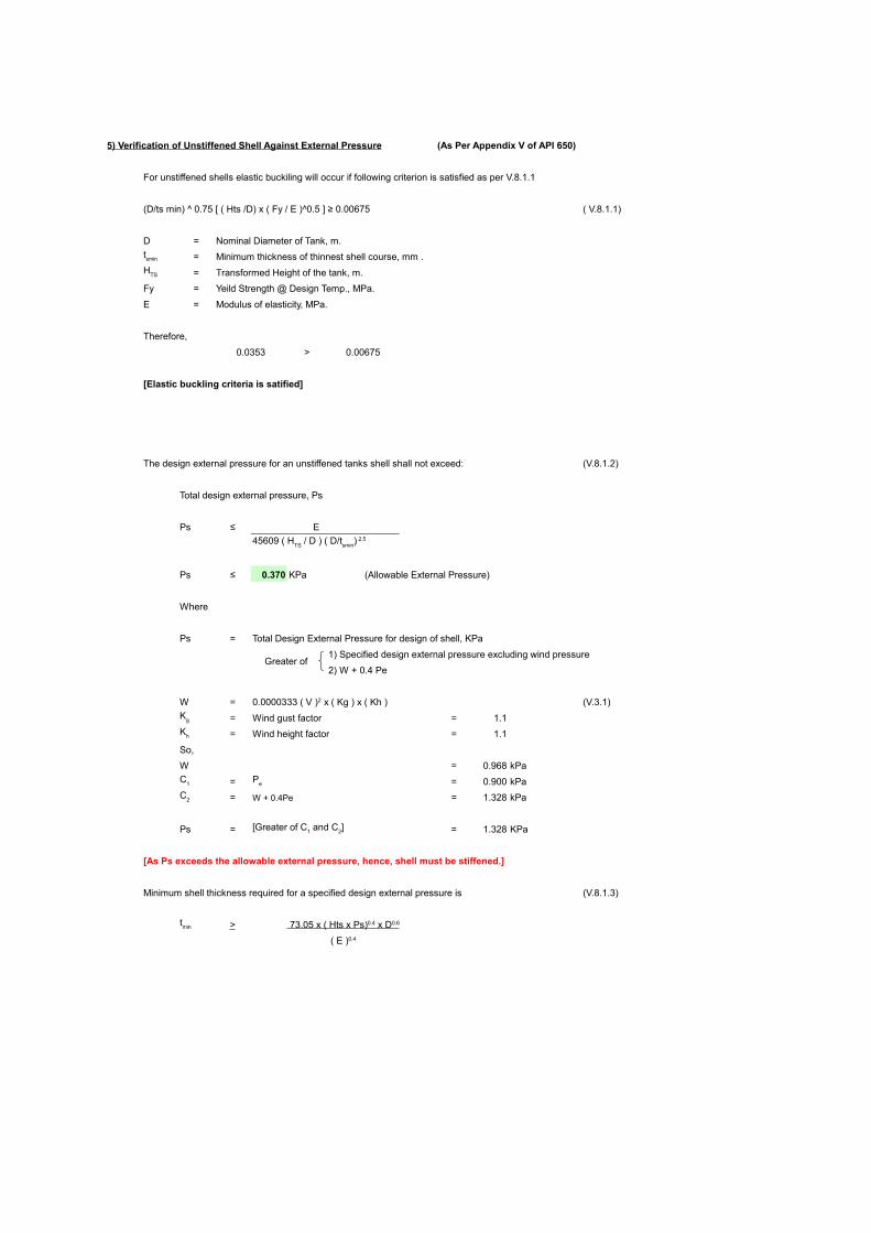
5) Verification of Unstiffened Shell Against External Pressure (As Per Appendix V of API 650)
For unstiffened shells elastic buckiling will occur if following criterion is satisfied as per V.8.1.1
(D/ts min) ^ 0.75 [ ( Hts /D) x ( Fy / E )^0.5 ] ≥ 0.00675 ( V.8.1.1)
D = Nominal Diameter of Tank, m.
= Minimum thickness of thinnest shell course, mm .
= Transformed Height of the tank, m.
Fy = Yeild Strength @ Design Temp., MPa.
E = Modulus of elasticity, MPa.
Therefore,
0.0353 > 0.00675
[Elastic buckling criteria is satified]
The design external pressure for an unstiffened tanks shell shall not exceed: (V.8.1.2)
Total design external pressure, Ps
Ps ≤ E
Ps ≤ 0.370 KPa (Allowable External Pressure)
Where
Ps = Total Design External Pressure for design of shell, KPa
Greater of 1) Specified design external pressure excluding wind pressure
2) W + 0.4 Pe
W = (V.3.1)
= Wind gust factor = 1.1
= Wind height factor = 1.1
So,
W = 0.968 kPa
= = 0.900 kPa
= W + 0.4Pe = 1.328 kPa
Ps = = 1.328 KPa
[As Ps exceeds the allowable external pressure, hence, shell must be stiffened.]
Minimum shell thickness required for a specified design external pressure is (V.8.1.3)
>
tsmin
HTS
45609 ( HTS
/ D ) ( D/tsmin
) 2.5
0.0000333 ( V )2 x ( Kg ) x ( Kh )
Kg
Kh
C1
Pe
C2
[Greater of C1 and C2]
tmin 73.05 x ( Hts x Ps) 0.4 x D 0.6
( E )0.4
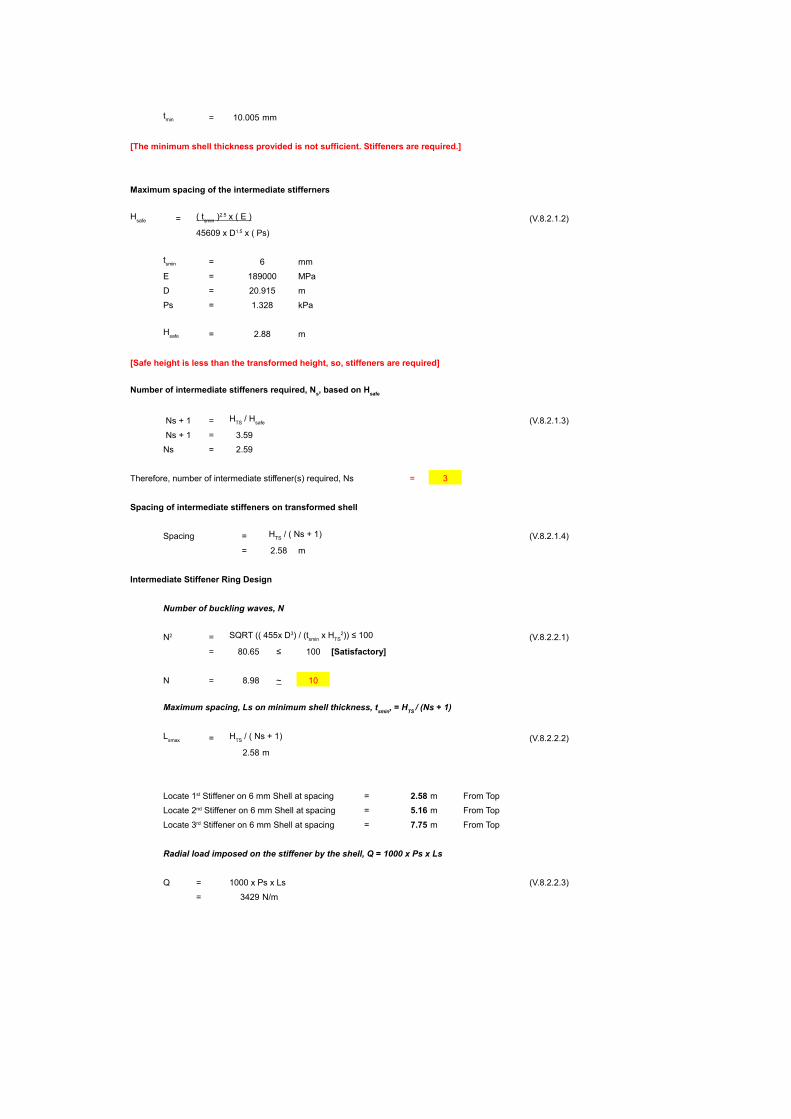
= 10.005 mm
[The minimum shell thickness provided is not sufficient. Stiffeners are required.]
Maximum spacing of the intermediate stifferners
= (V.8.2.1.2)
= 6 mm
E = 189000 MPa
D = 20.915 m
Ps = 1.328 kPa
= 2.88 m
[Safe height is less than the transformed height, so, stiffeners are required]
Ns + 1 = (V.8.2.1.3)
Ns + 1 = 3.59
Ns = 2.59
Therefore, number of intermediate stiffener(s) required, Ns = 3
Spacing of intermediate stiffeners on transformed shell
Spacing = (V.8.2.1.4)
= 2.58 m
Intermediate Stiffener Ring Design
Number of buckling waves, N
= (V.8.2.2.1)
= 80.65 ≤ 100 [Satisfactory]
N = 8.98 ~ 10
= (V.8.2.2.2)
2.58 m
= 2.58 m From Top
= 5.16 m From Top
= 7.75 m From Top
Radial load imposed on the stiffener by the shell, Q = 1000 x Ps x Ls
Q = 1000 x Ps x Ls (V.8.2.2.3)
= 3429 N/m
tmin
Hsafe
( t smin
) 2.5 x ( E )
45609 x D1.5 x ( Ps)
tsmin
Hsafe
Number of intermediate stiffeners required, Ns, based on Hsafe
HTS / Hsafe
HTS / ( Ns + 1)
N2 SQRT (( 455x D3) / (tsmin x HTS2)) ≤ 100
Maximum spacing, Ls on minimum shell thickness, tsmin
, = HTS
/ (Ns + 1)
Lsmax
HTS
/ ( Ns + 1)
Locate 1st Stiffener on 6 mm Shell at spacing
Locate 2nd Stiffener on 6 mm Shell at spacing
Locate 3rd Stiffener on 6 mm Shell at spacing
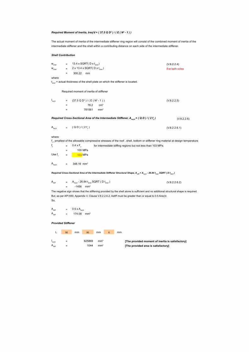
The actual moment of inertia of the intermediate stiffener ring region will consist of the combined moment of inertia of the
intermediate stiffener and the shell within a contributing distance on each side of the intermediate stiffener.
Shell Contribution
= (V.8.2.2.4)
= For both sides
= 300.22 mm
where
Required moment of inertia of stiffener
= (V.8.2.2.5)
= 78.2
= 781561
(V.8.2.2.6)
= (V.8.2.2.6.1)
where
= for intermediate stiffing regions but not less than 103 MPa.
= 100 MPa
= 103 MPa
= 348.16
= (V.8.2.2.6.2)
= -1456
The negative sign shows that the stiffening provided by the shell alone is sufficient and no additional structural shape is required.
But, as per API 650, Appendix V, Clause V.8.2.2.6.2, Astiff must be greater than or equal to 0.5 Areq'd.
So,
=
= 174.08
Provided Stiffener
L 90 mm 90 mm 6 mm
= 825869 [The provided moment of inertia is satisfactory]
= 1044 [The provided area is satisfactory]
Required Moment of Inertia, Ireq'd = ( 37.5 Q D3 ) / ( E ( N2 - 1 ) )
wshell 13.4 x SQRT( D x tshell )
wshell
2 x 13.4 x SQRT( D x tshell
)
tshell = actual thickness of the shell plate on which the stiffener is located.
Ireq'd (37.5 Q D3 ) / ( E ( N2 - 1 ) )
cm4
mm4
Required Cross-Sectional Area of the Intermediate Stiffener, Areq'd = ( Q D ) / ( 2 fc )
Areq'd
( Q D ) / ( 2 fc )
fc = smallest of the allowable compressive stresses of the roof , shell, bottom or stiffener ring material at design temperature
fc 0.4 x Fy
Use fc
Areq'd
mm2
Required Cross-Sectional Area of the Intermediate Stiffener Structural Shape, Astiff
= Areq'd
- 26.84 tshell
SQRT ( D tshell
)
Astiff Areq'd - 26.84 tshell SQRT ( D tshell )
mm2
Astiff 0.5 x Areq'd
Astiff mm2
Ireq'd
mm4
Astiff mm2
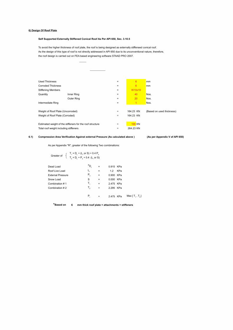
6) Design Of Roof Plate
Self Supported Externally Stiffened Conical Roof As Per API 650, Sec. 3.10.5
To avoid the higher thickness of roof plate, the roof is being designed as externally stiffeneed conical roof.
As the design of this type of roof is not directly addressed in API 650 due to its unconventional nature, therefore,
the roof design is carried out on FEA based engineering software STAAD PRO 2007.
Used Thickness = 6 mm
Corroded Thickness = 6 mm
Stiffening Members = W10x19
Quantity Inner Ring = 40 Nos.
Outer Ring = 20 Nos.
Intermediate Ring = 1 Nos.
Weight of Roof Plate (Uncorroded) = 164.23 KN (Based on used thickness)
Weight of Roof Plate (Corroded) = 164.23 KN
Estimated weight of the stiffeners for the roof structure = 100 KN
Total roof weight including stiffeners = 264.23 KN
6.1) Compression Area Verification Against external Pressure (As calculated above ) (As per Appendix V of API 650)
As per Appendix "R", greater of the following Two combinations:
Greater of
Dead Load = 0.915 KPa
Roof Live Load = 1.2 KPa
External Pressure = 0.900 KPa
Snow Load S = 0.000 KPa
Combination # 1 = 2.475 KPa
Combination # 2 = 2.295 KPa
= 2.475 KPa
6 mm thick roof plate + attachments + stiffeners
T1 = D
L + (L
r or S) + 0.4 P
e
T2 = DL + Pe + 0.4 (Lr or S)
*DL
Lr
Pe
T1
T2
Pr Max [ T1 , T2 ]
*Based on
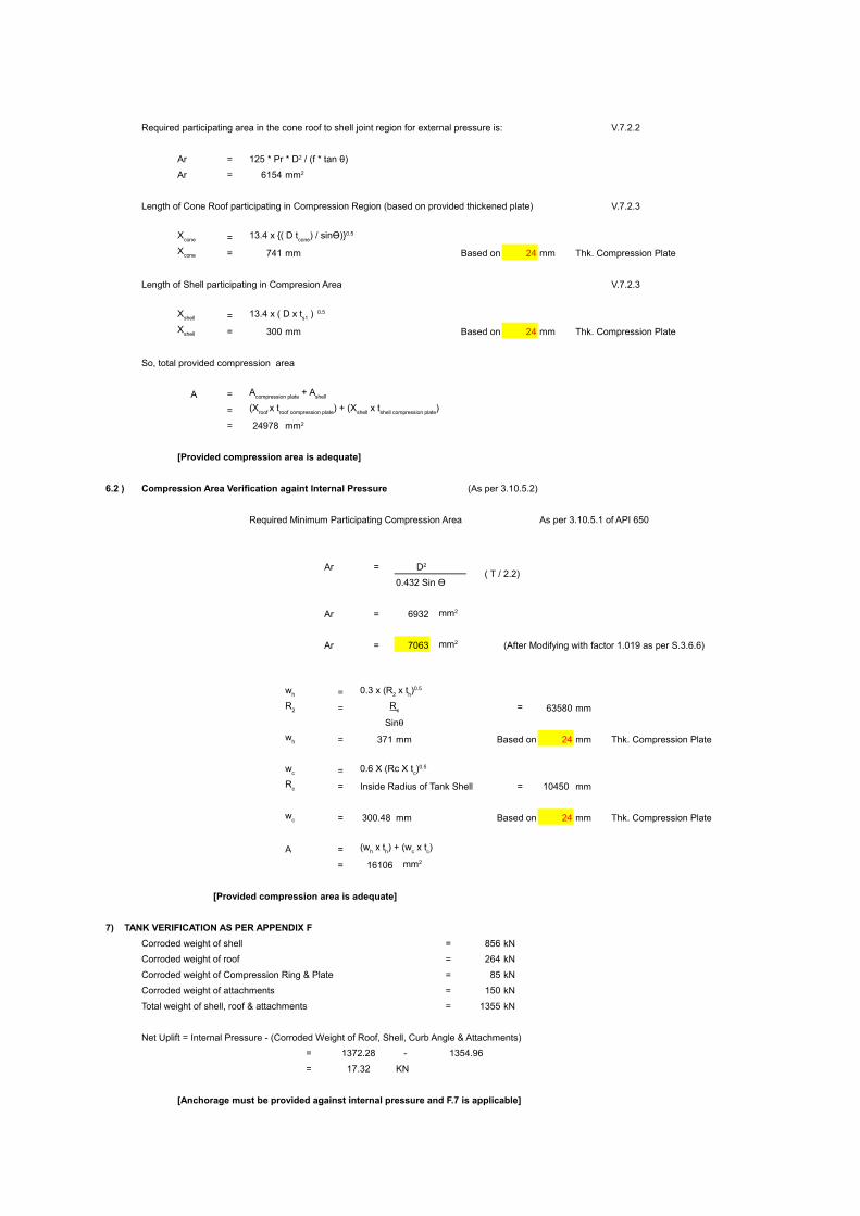
Required participating area in the cone roof to shell joint region for external pressure is: V.7.2.2
Ar =
Ar = 6154
Length of Cone Roof participating in Compression Region (based on provided thickened plate) V.7.2.3
=
= 741 mm Based on 24 mm Thk. Compression Plate
Length of Shell participating in Compresion Area V.7.2.3
=
= 300 mm Based on 24 mm Thk. Compression Plate
So, total provided compression area
A =
=
= 24978
[Provided compression area is adequate]
6.2 ) Compression Area Verification againt Internal Pressure (As per 3.10.5.2)
Required Minimum Participating Compression Area As per 3.10.5.1 of API 650
Ar =( T / 2.2)
0.432 Sin Ө
Ar = 6932
Ar = 7063 (After Modifying with factor 1.019 as per S.3.6.6)
=
= = 63580 mm
= 371 mm Based on 24 mm Thk. Compression Plate
=
= Inside Radius of Tank Shell = 10450 mm
= 300.48 mm Based on 24 mm Thk. Compression Plate
A =
= 16106
[Provided compression area is adequate]
7) TANK VERIFICATION AS PER APPENDIX F
Corroded weight of shell = 856 kN
Corroded weight of roof = 264 kN
Corroded weight of Compression Ring & Plate = 85 kN
Corroded weight of attachments = 150 kN
Total weight of shell, roof & attachments = 1355 kN
Net Uplift = Internal Pressure - (Corroded Weight of Roof, Shell, Curb Angle & Attachments)
= 1372.28 - 1354.96
= 17.32 KN
[Anchorage must be provided against internal pressure and F.7 is applicable]
125 * Pr * D2 / (f * tan θ)
mm2
Xcone
13.4 x {( D tcone
) / sinӨ)}0.5
Xcone
Xshell 13.4 x ( D x ts1 ) 0.5
Xshell
Acompression plate + Ashell
(Xroof x troof compression plate) + (Xshell x tshell compression plate)
mm2
D2
mm2
mm2
wh 0.3 x (R2 x th)0.5
R2 R c
Sinw
h
wc
0.6 X (Rc X tc)0.5
Rc
wc
(wh x th) + (wc x tc)
mm2
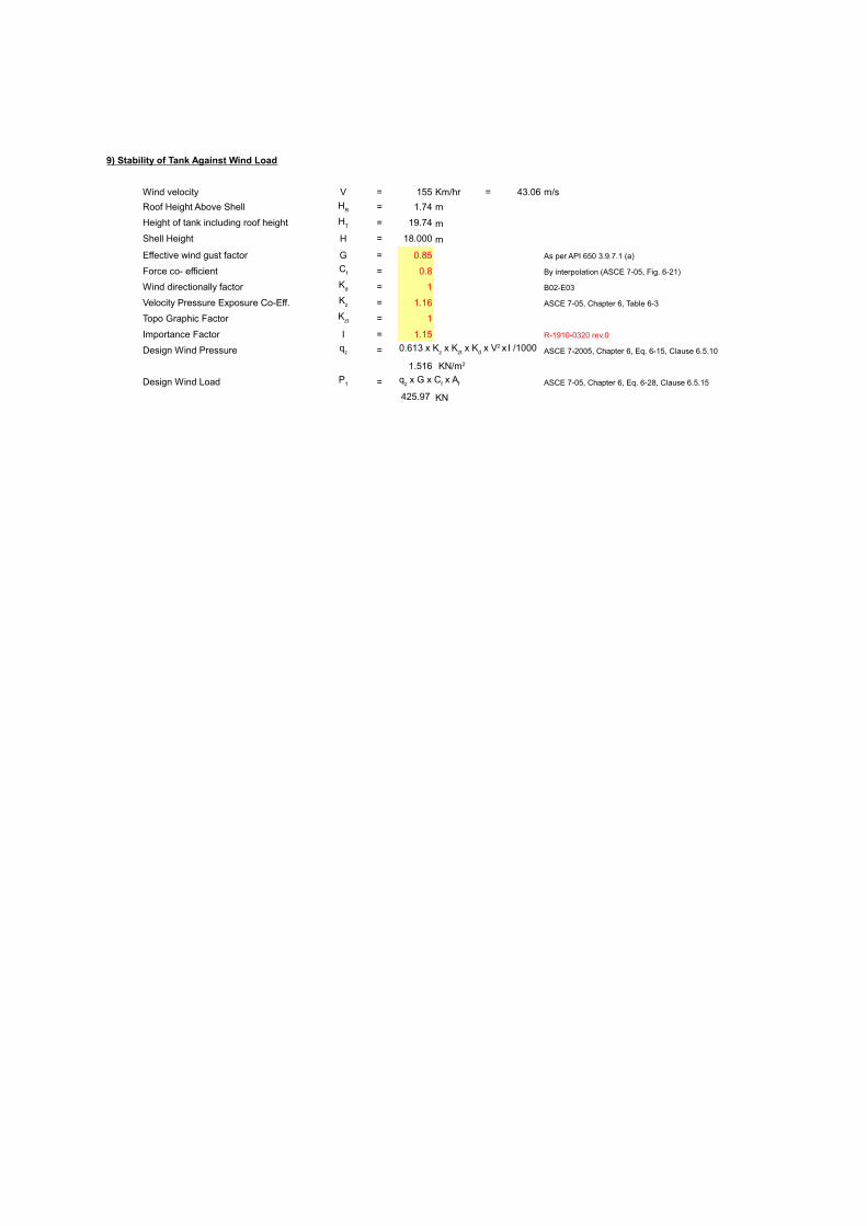
9) Stability of Tank Against Wind Load
Wind velocity V = 155 Km/hr = 43.06 m/s
Roof Height Above Shell = 1.74 m
Height of tank including roof height = 19.74 m
Shell Height H = 18.000 m
Effective wind gust factor G = 0.85 As per API 650 3.9.7.1 (a)
Force co- efficient = 0.8 By interpolation (ASCE 7-05, Fig. 6-21)
Wind directionally factor = 1 B02-E03
Velocity Pressure Exposure Co-Eff. = 1.16 ASCE 7-05, Chapter 6, Table 6-3
Topo Graphic Factor = 1
Importance Factor I = 1.15 R-1910-0320 rev.0
Design Wind Pressure = ASCE 7-2005, Chapter 6, Eq. 6-15, Clause 6.5.10
1.516
Design Wind Load = ASCE 7-05, Chapter 6, Eq. 6-28, Clause 6.5.15
425.97 KN
HR
HT
Cf
Kd
Kz
Kzt
qz 0.613 x Kz x Kzt x Kd x V2 x I /1000
KN/m2
P1 qz x G x Cf x Af
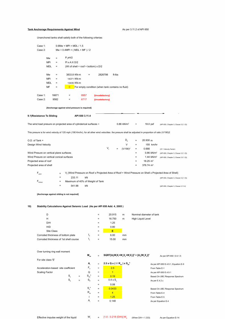
Tank Anchorage Requirements Against Wind As per 3.11.2 of API 650
Unanchored tanks shall satisfy both of the following criterias:
Case 1: 0.6Mw + MPi < MDL / 1.5
Case 2: Mw + 0.4MPi < ( MDL + MF ) / 2
Mw =
MPi = Pi x A X D/2
MDL = (Wt of shell + roof + bottom) x D/2
Mw = 3833.8 KN-m = 2826798 ft-lbs
MPi = 14371 KN-m
MDL = 13435 KN-m
MF = 0 For empty condition (when tank contains no fluid)
Case 1: 16671 < 8957 [Unsatisfactory]
Case 2: 9582 < 6717 [Unsatisfactory]
[Anchorage against wind pressure is required]
9.1)Resistance To Sliding API 650 3.11.4
The wind load presure on projected area of cylinderical surfaces = 0.86 = 18.0 psf (API 650, Chapter 3, Clause 3.2.1 (f))
This presure is for wind velocity of 120 mph (190 Km/hr), for all other wind velocities the presure shall be adjusted in proportion of ratio (V/190)2
O.D. of Tank = = 20.930 m
Design Wind Velocity V = 155 km/hr
= = 0.666 (Vf = Velocity Factor)
Wind Presure on vertical plane surfaces = 0.86 (API 650, Chapter 3, Clause 3.2.1 (f))
Wind Presure on vertical conical surfaces = 1.44 (API 650, Chapter 3, Clause 3.2.1 (f))
Projected area of roof = 18.25
Projected area of shell = 376.74
=
= 233.11 kN (API 650, Chapter 3, Clause 3.2.1 (f))
= Maximum of 40% of Weight of Tank
= 541.98 kN (API 650, Chapter 3, Clause 3.11.4)
[Anchorage against sliding is not required]
10) Stability Calculations Against Seismic Load (As per API 650 Add. 4, 2005 )
D = 20.915 m Nominal diameter of tank
H = 16.750 m High Liquid Level
D/H = 1.25
H/D = 0.80
Site Class = E
Corroded thickness of bottom plate = 6.00 mm
Corroded thickness of 1st shell course = 15.00 mm
Over turning ring wall moment
= As per API 650 E.6.1.5
For site class 'E'
= As per API 650 E.4.9.1, Equation E-9
Acceleration-based site coefficient = 2.5 From Table E-1
Scaling Factor Q = 1 As per API 650 E.4.9.1
= = 0.19 Based On UBC Response Spectrum
= = As per E.4.2.c
= 0.08
= 0.0433 Based On UBC Response Spectrum
= 4 From Table E-4
I = 1.25 From Table E-5
= 0.148 As per Equation E-4
Effective impulse weight of the liquid = (When D/H < 1.333) As per Equation E-14
= Weight of content based on design specific gravity of the product
= 44590.542 kN
= 44590542 N
= 32453 kN
= 32452677 N
As per E-6.1.2.1
= Height from the bottom of the shell to the center of action
of the lateral Siesmic force related to impulsive liquid force
= [0.5-0.094(D/H)]H (When D/H < 1.333) As per Equation E-17
= 6.409 m
= Total Weight of Shell and appurtenances (Uncorroded)
= 998 kN
= Height from the bottom of the tank shell to center of gravity
= 9 m
= Total Weight of fixed tank roof including framing (Uncorroded)
= 357 kN
= Height from the top of the shell to the roof and roof appurtenances
center of gravity
= 0.58 m
As per E.4.9.1.1
= As per Equation E-11
Where
K = 1.5 By Definition
= 2 From Table E-4
= 0.041 ≤
As Ac < Ai Condition staisfied
= Effective Convective (sloshing) portion of the liquid weight
= 0.23 x (D/H) Tanh (3.67 H/D) x Wp As per Equation E-15
= 12735 kN
= 12734504 N
= Height from the bottom of the tank shell to the center of action of
lateral siemic force related to convective liquid force
= [1-{Cosh((3.67 x H/D)-1)/((3.67 x H/D) Sinh((3.67 x H/D))}] x H
= 14.45 m As per Equation E-18
Therefore Ring Wall Moment
= 33092 KN-m
= 33091922 N-m = 24407278 ft-lbs
Resisting force to be adequate for tank stability J < 1.54
Anchorage Ratio J = Mrw As per API 650 E.6.2.1.1.1
Where = As per API 650 E.6.1.3
= From Equation E-4
= 0.5
= 0.0665
= As per API 650 E.6.2.1.1
Where
= Effective specific gravity including vertical seismic effects
= By Definition
= 0.77
= Corroded thickness of the bottom plate under the shell
extending at the distance L from the inside of the shell
= 6.00 mm
= 25951 N/m ≤ 345 N/m
= 345.3 N/m
0.3 kN/m
= As per API 650 E.6.2.1.1
= Roof load acting on the tank shell (Uncorroded)
= 5.427 KN/m
= 5427 N/m
= 21 KN/m
Therefore = 20621 N/m
Anchorage Ratio J = 3.705 < 1.54
Condition not satisfied tank is required to be anchored
Note:
As the anchorage ratio is greater than 1.54, Therefore as per table E-6, Tank is not stable
and mechanical anchorage is required.
10.1) Mechanicaly Anchored Tanks As per API 650 E.6.2.1.2
=
40% of uplift on shell circumfrence = 8 KN/m
= 84595 N = 85 KN
Design Load/Anchor in the seismic Condition =
= 231601 N = 232 KN
= 52066 lbs As per API 650 E.6.2.2.2
10.2) Shell Compression In Mechanicaly Anchored Tanks
=
= 7.83 Mpa
10.2) Allowable Longitudinal Membrane Compression Stress in Tank Shell As per API 650 E.6.2.2.3
Calculating value of =
= 26
=
Where
G x H = 13.24925
= 74
Therefore,
= 51 MPa
As ơc < Fc Condition Staisfied
11) Anchorage For Uplift Laod Cases, Per API 650 Table 3-21a
Design Pressure P = 4.00 kPa
= 16.07 in. of water
Test Pressure = 5.000 kPa
= 20.09 inches of water (1.25 times of Design Pressure)
Dead Load of shell minus any C.A. and any Dead Load other than roof
= Weight of shell (Corroded) (3.12.2 Table 3-21)
= 940726.17 N
= 211483.6 lbs
Dead Load of shell minus any C.A. and any Dead Load including roof plate
acting on the shell minus any C.A.
= Weight of shell (Corroded) + Weight of Roof (corroded)
= 1204958.0 N
= 270885.27 lbs
Dead Load of the shell using as built thicknesses and any dead load other than
roof plate acting on the shell using as built thickness
= Weight of Shell
= 940726.2 N
= 211483.6 lbs
Yield stress for Anchor Bolts
Fy = 36000 psi (From Table I Of B55-E01)
= 6 mm = 0.2362 in.
D = 20.915 m = 68.60 ft
Table 3 - 21
UPLIFT LOAD CASES
Design Pressure 60878.49 20000
Test Pressure 137916.98 20000
Wind Load -106060.31 28800
Seismic Load (4x Ms/D) -W2 1152254.73 28800
Design Pressure +Seismic 1484018.50 28800
Design Pressure + Wind 234774.79 20305
UPLIFT LOAD CASES
lbs
Design Pressure 2537 0.127 81.83
Test Pressure 5747 0.287 185.37
Wind Load -4419 -0.153 -99.00
Seismic Load 48011 1.667 1075.50
Design Pressure + Seismic 61834 2.147 1385.17
Design Pressure + Wind 9782 0.482 310.82
Design tension load per anchor = API 3.11.3
Diameter of anchor circle d = 21.150 m
No. of Anchor Bolts N = 24
Weight of shell plus roof supported by the shell less 0.4 times the uplift from internal pressure, W = 656.05 KN
Design tension load per anchor based on wind loading = 2.876 KN = 2876 N
Design tension load per anchor based on Seismic loading = 232 KN = 231601 N
Design tension load per anchor 52066.051 lbs
= 1385
Provided Bolt Area M56 Bolt = 2030
= 1773 (Corroded Area)
[Area of the anchor bolt provided is sufficient]
12) Anchor Chair Calculations
As Per AISI E-l, Volume ll, Part Vll
Top Plate Thickness Calculations:
Top Plate Thickness
Where,
C = Top Plate Thickness
S = Stress At Point = 25 ksi (AISI E-1)
f = Distance From Outside Of = 2.00 in.
Top Plate To Edge Of Hole
g = Distance B/W Gussett Pl. = 5.51 in.
d = Anchor Bolt Diameter (corroded) = 2.09 in.
P
Design Load or Max. Allowable
= Anchor Bolt Load or 1.5 Times = 78.10 kips
Actual Bolt Load,whichever is
lesser
. So,
. Top Plate Thickness C = 1.584 in. = 40.2 mm
Actual Used Top Plate Thickness C = 44 mm = 1.732 in.
Top Plate Thickness Is Adequate
Anchor Chair Height Calculations:
=
Where;
Z = Reduction Factor =
a = Top Plate Width = 9.8425 in.
h = Anchor Chair Height = 11.8110 in.
R = Nominal Shell Radius = 411.7126 in.
t = Shell Thickness (Inc. reinf. Pad) = 1.1811 in.
m = Bottom Plate Thickness = 0.2362 in.
e = Anchor Bolt Eccentricity = 4.3307 in.
= Allowable Stress = 19.1450 ksi
So,
Z = 0.9993
Now,
= 15.126 ksi
Anchor Chair Height Is Adequate
Gussett Plate Thickness Calculations: = 0.04 ( h - C ) or 1/2"
Gussett Plate Thickness = 0.403 in.
= 10.2 mm
Gussett Plate Thickness Provided = 14 mm
Gussett Plate Thickness Is Adequate
The self weight of roof and live load will be transferred to tank shell
Live load transferred to foundation
The live load on floating roof is not transferred to the foundation through shell as roof is floating type and not supported on tank shell.
When tank is empty than the live load shall be transferred through the deck and pontoon supports as concentrated loads.
Live Load on Floating Roof Supports 0.6
Maximum Live Load on Pontoon Support 7.07 kN
Maximum Live Load on Deck Support 5.66 kN
Live Load on roof = 1.20
Area of Roof = 343.73
Total Live Load = 412.47 kN
Circumference of Tank C = π x D = 65.75 m
Live Load transferred to Foundation = 6.27 kN/m
Dead load transferred to foundation
The self weight of floating roof is not transferred to the foundation through shell as roof is floating type & not supported on tank shell.
When tank is empty than the self weight of flating roof shall be transferred through deck & pontoon supports as concentrated loads.
Maximum dead load on pontoon support = 16.371 kN
Maximum dead load on deck support = 4.0741 kN
Self Weight of Roof = 264.23 kN
Self Weight of Floating Roof = 284.49 kN
Self Weight of Bottom Plate = 163.56 kN
Self Weight of Shell = 940.73 kN
Self Weight of Attachmnets = 150.00 kN
Total Dead Load acting on shell = 1354.96 kN
Dead Load Transferred to Foundation = 20.61 kN/m
Operating & Hydrostatic Test Loads
Self Weight of Tank 1803.01 KN = 183793 kgs
Weight of Fluid in Tank at Operating Conditions 44590.54 KN = 4545417 kgs
Weight of Water in Tank at Hydrotest Conditions 60666.25 KN = 6184123 kgs
Uniform Load Operating Condition = (Self wt.+ Fluid)/Area 135.23
Uniform Load Hydrotest Condition = (Self wt.+ Water)/Area 181.83
Wind Load Transferred to Foundation
Base Shear due to wind load = 388.35 kN
Reaction due to wind load = 2.79 kN/m
Moment due to wind load = 3833.76 kN-m
Base Shear due to seismic load = 5069.03 kN
Reaction due to seismic load = 24.05 kN/m
Moment due to seismic load = 33091.92 kN-m
Summary of Foundation Loading Data
Dead load, shell, roof & ext. structure loads 20.61 kN/m
Live Load 6.27 kN/m
Uniform load, operating condition 135.23
Uniform load, hydrotest load 181.83
Base shear due to seismic load Fs = 5069.03 kN
Reaction due to seismic load Rs = 24.05 kN/m
Moment due to seismic load Ms = 33091.92 kN-m
Base shear due to wind 388.35 kN
Reaction due to wind 2.79 kN/m
Moment due to wind load 3833.76 kN-m
Note : Consider 15-20 % variation in weight while designing the foundation
P1xH/2
kN/m2
D0
Vf (V/190)2
kN/m2
kN/m2
m2
m2
Fwind
Vf (Wind Pressure on Roof x Projected Area of Roof + Wind Pressure on Shell x Projected Area of Shell)
Ffriction
tbts
Mrw SQRT[Ai(WiXi+WsXs+WrXr)]2 + [Ac(WcXc)]
2
Ai 2.5 x Q x ( I / Rwi ) x Sa0*
Fa
Ss Sa0*
S0
SP
0.4 x Ss
Sa*
Rwi
Ai
Wi [1.0 - 0.218 (D/H)] Wp
Wp
Wi
Xi
Xi
Ws
Xs
Wr
Xr
Ac
Q x K x (I / Rwc
) x Sa* ≤ Ai
Rwc
Ac
Ai
Wc
Xc
Mrw
D2(wt(1-0.4Av)+wa)
Av 0.14 x SDS
SDS
2.5 x Q x Fa x S0
Av
wa 99 x ta x (Fy x H x Ge)^0.5 ≤ 1.28 x H x D x Ge
Ge
G x (1-0.4 x Av)
ta
ta
wa
wa
wa
wt [(Ws/πD)+wrs)]
wrs
wt
wAB {(1.273 Mrw/D2) - wt (1 - 0.4 x Av)} + 40% of uplift on shell circumfrence
wAB
wAB
x (π x D/Na)
PAB
ơc {wt(1+ 0.4 x Av) + (1.273 Mrw/D2)} x (1/1000ts)
G x H x D2
t2
When GHD2 / t2 is less than 44, then
Fc
{(83x ts)/(2.5 x D)} + 7.5 x SQRT(G x H) < 0.5 x F
ty
0.5 x Fty
Fc
Pt
W1
W2
W3
Th
NET UPLIFT FORMULA, U (lbf)
*Fall
For Anchor Bolts(PSI)
((P - 8th) x D2 x 4.08) - W1
((Pt - 8th) x D2 x 4.08) - W1
(4 x Mw / D) - W2
((P-8th) x D² x 4.08) + (4 x Ms/D)-W1
((P-8th) x D² x 4.08) + (4 x Mw/D)-W1
tb = U / N A
r = t
b/F
all
in.2 mm2
4 MW/ dN - W/N
tB
PAB
tB
Areq. mm2
Aprov. mm2
mm2
C = [P(0.375g-0.22d)/Sf]0.5
Sind. (Pe/t2)[{1.32*Z/(1.43*a*h2/Rt)+(4ah2)0.333}+{0.031/(Rt)0.5}]
1/[{.177am(m/t)2/(Rt)0.5}+1]
Sall.
Sind.
Jmin
13) Foundation Loading Data
kN/m2
PLp = WL*Ap/Np
PLd = WL*A1/Nd
Lr kN/m2
Ar m2
WL = Lr x Ar
LL = WL / C
Pdp = Wdp*Ap/Np
Pdd = Wdd*A1/Nd
Wr
Wfr
Wb
Ws
Wa
Wr + Ws + Wa
Wd = D
L
Wr + W
s + W
a + W
b + W
fr=
Wf =
Ww =
Wo = KN/m2
Wh = KN/m2
Fw
Rw
Mw
Fs
Rs
Ms
DL =
LL =
Wo = kN/m2
Wh= kN/m2
Fw =
Rw =
Mw=
P
Jmin g
a
Ød
f
eCh
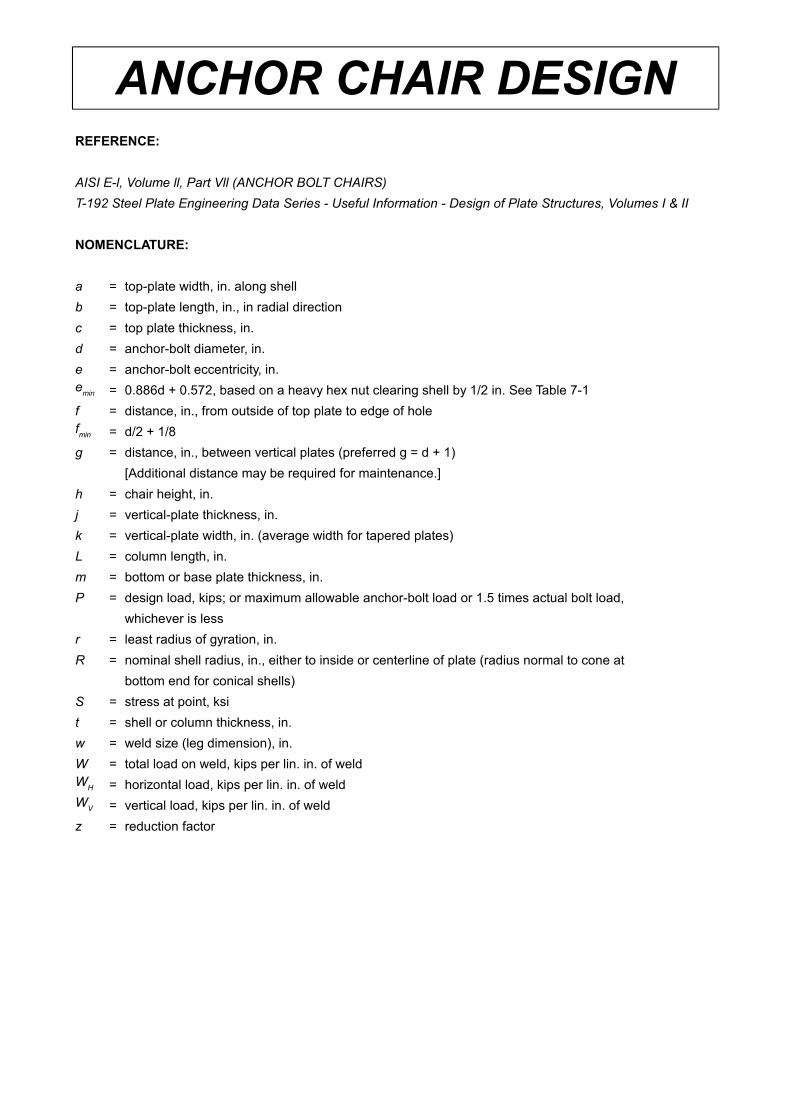
ANCHOR CHAIR DESIGNREFERENCE:
AISI E-l, Volume ll, Part Vll (ANCHOR BOLT CHAIRS)
T-192 Steel Plate Engineering Data Series - Useful Information - Design of Plate Structures, Volumes I & II
NOMENCLATURE:
a = top-plate width, in. along shell
b = top-plate length, in., in radial direction
c = top plate thickness, in.
d = anchor-bolt diameter, in.
e = anchor-bolt eccentricity, in.
= 0.886d + 0.572, based on a heavy hex nut clearing shell by 1/2 in. See Table 7-1
f = distance, in., from outside of top plate to edge of hole
= d/2 + 1/8
g = distance, in., between vertical plates (preferred g = d + 1)
[Additional distance may be required for maintenance.]
h = chair height, in.
j = vertical-plate thickness, in.
k = vertical-plate width, in. (average width for tapered plates)
L = column length, in.
m = bottom or base plate thickness, in.
P = design load, kips; or maximum allowable anchor-bolt load or 1.5 times actual bolt load,
whichever is less
r = least radius of gyration, in.
R = nominal shell radius, in., either to inside or centerline of plate (radius normal to cone at
bottom end for conical shells)
S = stress at point, ksi
t = shell or column thickness, in.
w = weld size (leg dimension), in.
W = total load on weld, kips per lin. in. of weld
= horizontal load, kips per lin. in. of weld
= vertical load, kips per lin. in. of weld
z = reduction factor
emin
fmin
WH
WV
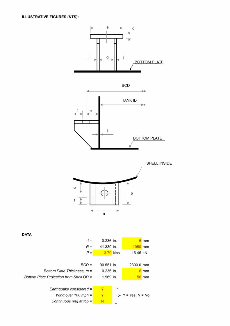
ILLUSTRATIVE FIGURES (NTS):
DATA
t = 0.236 in. 6 mm
R = 41.339 in. 1050 mm
P = 3.70 kips 16.46 kN
BCD = 90.551 in. 2300.0 mm
Bottom Plate Thickness, m = 0.236 in. 6 mm
Bottom Plate Projection from Shell OD = 1.969 in. 50 mm
Earthquake considered = Y
Wind over 100 mph = Y Y = Yes, N = No
Continuous ring at top = N
j
c
BOTTOM PLATEgj
a
ef
TANK ID
BCD
t
BOTTOM PLATE
a
b
e
f
SHELL INSIDE

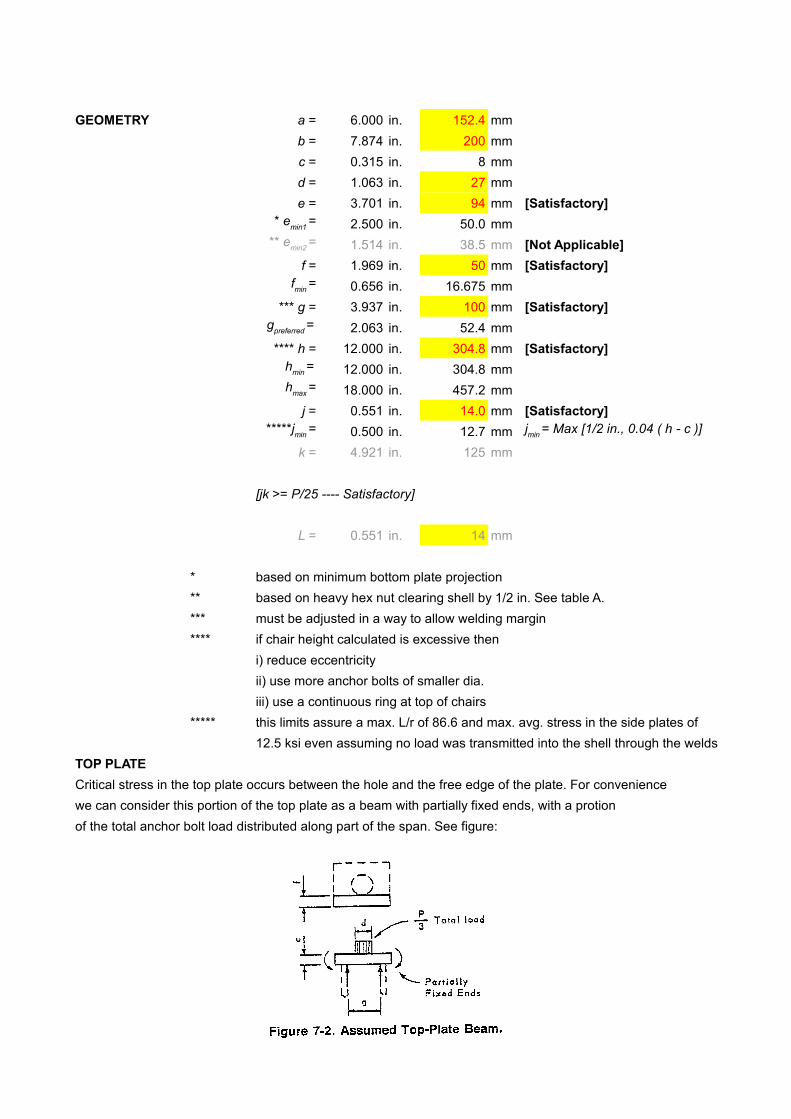
GEOMETRY a = 6.000 in. 152.4 mm
b = 7.874 in. 200 mm
c = 0.315 in. 8 mm
d = 1.063 in. 27 mm
e = 3.701 in. 94 mm [Satisfactory]
2.500 in. 50.0 mm
1.514 in. 38.5 mm [Not Applicable]
f = 1.969 in. 50 mm [Satisfactory]
0.656 in. 16.675 mm
*** g = 3.937 in. 100 mm [Satisfactory]
2.063 in. 52.4 mm
**** h = 12.000 in. 304.8 mm [Satisfactory]
12.000 in. 304.8 mm
18.000 in. 457.2 mm
j = 0.551 in. 14.0 mm [Satisfactory]
0.500 in. 12.7 mm
k = 4.921 in. 125 mm
[jk >= P/25 ---- Satisfactory]
L = 0.551 in. 14 mm
* based on minimum bottom plate projection
** based on heavy hex nut clearing shell by 1/2 in. See table A.
*** must be adjusted in a way to allow welding margin
**** if chair height calculated is excessive then
i) reduce eccentricity
ii) use more anchor bolts of smaller dia.
iii) use a continuous ring at top of chairs
***** this limits assure a max. L/r of 86.6 and max. avg. stress in the side plates of
12.5 ksi even assuming no load was transmitted into the shell through the welds
TOP PLATE
Critical stress in the top plate occurs between the hole and the free edge of the plate. For convenience
we can consider this portion of the top plate as a beam with partially fixed ends, with a protion
of the total anchor bolt load distributed along part of the span. See figure:
* emin1
=
** emin2
=
fmin
=
gpreferred
=
hmin
=
hmax
=
*****jmin
= jmin
= Max [1/2 in., 0.04 ( h - c )]
Using above philosophy, thickness of top plate can be calculated with the help of following expression:

Let S = 25.00 ksi 172.37 MPa
c = 0.31 in. 7.8 mm
0.31 in. 8 mm [Satisfactory]
The thickness of top plate has been calculated based on 25 ksi stress value.
Actual stress in the top plate which occurs between the hole and the free edge of the plate can be evaluated
using the following expression:
S = 11.56 ksi 79.72 MPa [Satisfactory]
MAXIMUM STRESS IN SHELL
Chair must be high enough to distribute anchor bolt load to shell without overstressing it. The difficulty lies in
the bending caused by eccentricity of the anchor bolt with respect the shell. Except for the case where a
continuous ring is used at the top of chairs, maximum stress occurs in the vertical direction and is a
combination of bending plus direct stress. Formula which follow are approximations, based on the work
of Bjilaard.
Hence, maximum stress (i.e., a combination of bending plus direct stress) in vertical direction can be
evaluated using following expression:
Z = 0.926
S = 15.98 ksi 110.17 MPa [Satisfactory]
cused
=
S=Pe
t2 [1.32Z
1.43ah2
Rt+(4 ah2 )0 . 333
+0 .031
√Rt ]
c=[ PSf
( 0.375 g−0 .22d )]0.5
S=P
fc2(0 .375g−0 .22g )
Z=1.0
0 .177am√Rt (mt )
2
+1 .0
Maximum recommended stress is 25 ksi.
This is a local stress occuring just above the top of the chair, a higher than normal stress is justified but an
increase for temporary loads, such as earthquake or wind is not recommended
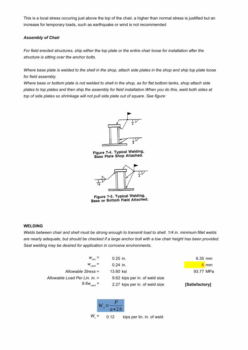
Assembly of Chair
For field erected structures, ship either the top plate or the entire chair loose for installation after the
structure is sitting over the anchor bolts.
Where base plate is welded to the shell in the shop, attach side plates in the shop and ship top plate loose
for field assembly.
Where base or bottom plate is not welded to shell in the shop, as for flat bottom tanks, shop attach side
plates to top plates and then ship the assembly for field installation.When you do this, weld both sides at
top of side plates so shrinkage will not pull side plate out of square. See figure:
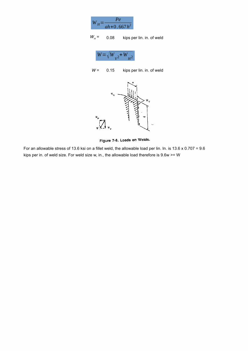
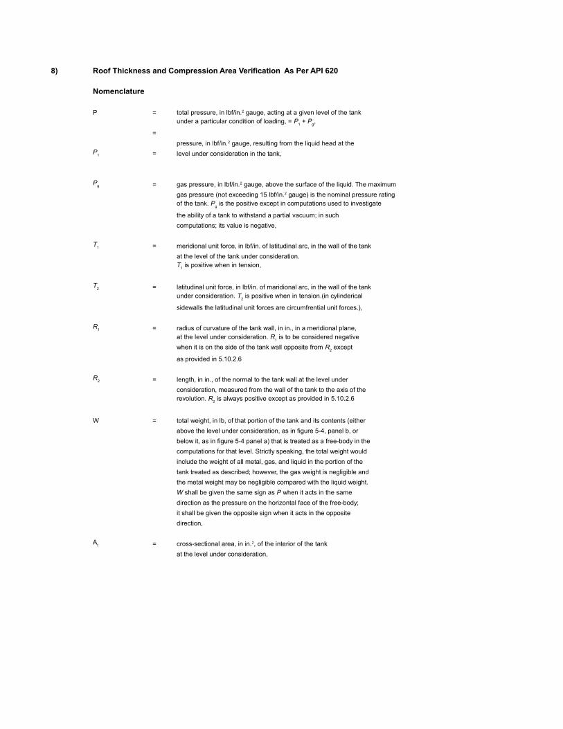
WELDING
Welds between chair and shell must be strong enough to transmit load to shell. 1/4 in. minimum fillet welds
are nearly adequate, but should be checked if a large anchor bolt with a low chair height has been provided.
Seal welding may be desired for application in corrosive environments.
0.25 in. 6.35 mm
0.24 in. 6 mm
Allowable Stress = 13.60 ksi 93.77 MPa
Allowable Load Per Lin. in. = 9.62 kips per in. of weld size
2.27 kips per in. of weld size [Satisfactory]
0.12 kips per lin. in. of weld
wmin
=
wused
=
9.6wused
=
Wv =
W v=P
a+2h
0.08 kips per lin. in. of weld
W = 0.15 kips per lin. in. of weld
For an allowable stress of 13.6 ksi on a fillet weld, the allowable load per lin. In. is 13.6 x 0.707 = 9.6
kips per in. of weld size. For weld size w, in., the allowable load therefore is 9.6w >= W
WH =
W=√WV2+W
H2
W H=Pe
ah+0 .667h2
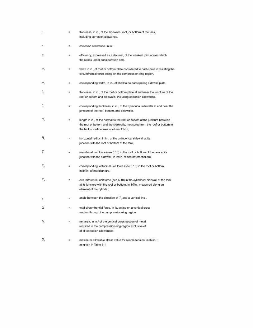
8) Roof Thickness and Compression Area Verification As Per API 620
Nomenclature
P =
=
= level under consideration in the tank,
=
the ability of a tank to withstand a partial vacuum; in such
computations; its value is negative,
= meridional unit force, in lbf/in. of latitudinal arc, in the wall of the tank
at the level of the tank under consideration.
= latitudinal unit force, in lbf/in. of maridional arc, in the wall of the tank
sidewalls the latitudinal unit forces are circumfrential unit forces.),
= radius of curvature of the tank wall, in in., in a meridional plane,
as provided in 5.10.2.6
= length, in in., of the normal to the tank wall at the level under
consideration, measured from the wall of the tank to the axis of the
W = total weight, in lb, of that portion of the tank and its contents (either
above the level under consideration, as in figure 5-4, panel b, or
below it, as in figure 5-4 panel a) that is treated as a free-body in the
computations for that level. Strictly speaking, the total weight would
include the weight of all metal, gas, and liquid in the portion of the
tank treated as described; however, the gas weight is negligible and
the metal weight may be negligible compared with the liquid weight.
direction as the pressure on the horizontal face of the free-body;
it shall be given the opposite sign when it acts in the opposite
direction,
=
at the level under consideration,
total pressure, in lbf/in.2 gauge, acting at a given level of the tank under a particular condition of loading, = P
1 + P
g,
pressure, in lbf/in.2 gauge, resulting from the liquid head at the P
1
Pg gas pressure, in lbf/in.2 gauge, above the surface of the liquid. The maximum
gas pressure (not exceeding 15 lbf/in.2 gauge) is the nominal pressure ratingof the tank. P
g is the positive except in computations used to investigate
T1
T1 is positive when in tension,
T2
under consideration. T2 is positive when in tension.(in cylinderical
R1
at the level under consideration. R1 is to be considered negative
when it is on the side of the tank wall opposite from R2 except
R2
revolution. R2 is always positive except as provided in 5.10.2.6
W shall be given the same sign as P when it acts in the same
At cross-sectional area, in in.2, of the interior of the tank
t = thickness, in in., of the sidewalls, roof, or bottom of the tank,
including corrosion allowance,
c = corrosion allowance, in in.,
E = efficiency, expressed as a decimal, of the weakest joint across which
the stress under consideration acts.
= width in in., of roof or bottom plate considered to participate in resisting the
circumfrential force acting on the compression-ring-region,
= corresponding width, in in., of shell to be participating sidewall plate,
= thickness, in in., of the roof or bottom plate at and near the juncture of the
roof or bottom and sidewalls, including corrosion allowance,
= corresponding thickness, in in., of the cylindrical sidewalls at and near the
juncture of the roof, bottom, and sidewalls,
= length in in., of the normal to the roof or bottom at the juncture between
the roof or bottom and the sidewalls, measured from the roof or bottom to
the tank's vertical axis of of revolution,
= horizontal radius, in in., of the cylinderical sidewall at its
juncture with the roof or bottom of the tank,
= meridional unit force (see 5.10) in the roof or bottom of the tank at its
juncture with the sidewall, in lbf/in. of circumferential arc,
= corresponding latitudinal unit force (see 5.10) in the roof or bottom,
in lbf/in. of meridian arc,
= circumferential unit force (see 5.10) in the cylindrical sidewall of the tank
at its juncture with the roof or bottom, in lbf/in., measured along an
element of the cylinder,
a =
Q = total circumfrential force, in lb, acting on a vertical cross
section through the compression-ring region,
=
required in the compression-ring-region exclusive of
of all corrosion allowances.
=
as given in Table 5-1
wh
wc
th
tc
R2
Rc
T1
T2
T2s
angle between the direction of T1 and a vertical line ,
Ac net area, in in.2 of the vertical cross section of metal
Sts maximum allowable stress value for simple tension, in lbf/in.2,


8.1) Design Data
Design Code API 620, 10th EDD. 2002, ADD. 01
Item TK-59301
Description Acetone Storage Tank
Material A 240 Type 304L
Design Density of Contents = 791
= 49.38
Density of Water for Hydrotest = 1000
= 62.43
Specific Gravity Of Contents = 0.791
Material Yield Strength = 148 MPa
= 21465.59 psi
Design Temperature = 90
Internal Pressure = 4.00 kPa
= 0.58 psi
= 83.54 psf
Extrenal Pressure = 0.90 kPa
= 0.13 psi
= 18.80 psf
Allowable Tensile Stress at Design Temperature = 110.00 MPa
= 15954 psi
Corrosion Allowance
Shell = 0.00 mm
= 0.00 in.
Bottom = 0.00 mm
= 0.00 in.
Roof = 0.00 mm
= 0.00 in.
Inside Dia of Tank D = 20900 mm
= 68.57 ft
= 822.83 in.
Nominal Dia of Tank = 20915 mm
= 68.62 ft
= 823.43 in.
Outside Dia of tank = 20930 mm
= 68.67 ft
= 824.02 in.
Height of Shell = 18000 mm
= 59.06 ft
Weight of Compression Ring & Plate = 19047 lbs
Weight of Accessories = 11240 lbs
Wind Velocity = 155 km/hr
= 96.31 mph
Yield Strength of Steel Structure = 36260 psi
Roof Angle = 9.46 degree
Kg/m3
lbs/ft3
Kg/m3
lbs/ft3
OC
Dn
D0
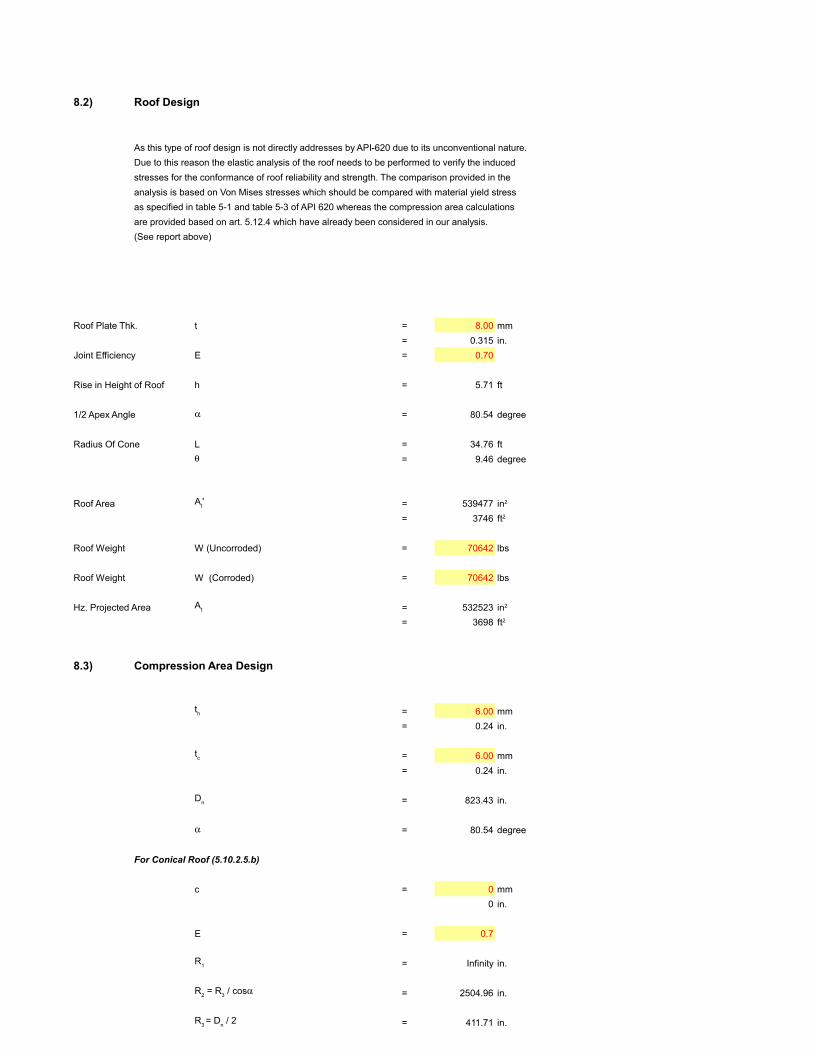
8.2) Roof Design
As this type of roof design is not directly addresses by API-620 due to its unconventional nature.
Due to this reason the elastic analysis of the roof needs to be performed to verify the induced
stresses for the conformance of roof reliability and strength. The comparison provided in the
analysis is based on Von Mises stresses which should be compared with material yield stress
as specified in table 5-1 and table 5-3 of API 620 whereas the compression area calculations
are provided based on art. 5.12.4 which have already been considered in our analysis.
(See report above)
Roof Plate Thk. t = 8.00 mm
= 0.315 in.
Joint Efficiency E = 0.70
Rise in Height of Roof h = 5.71 ft
1/2 Apex Angle = 80.54 degree
Radius Of Cone L = 34.76 ft
= 9.46 degree
Roof Area = 539477
= 3746
Roof Weight W (Uncorroded) = 70642 lbs
Roof Weight W (Corroded) = 70642 lbs
Hz. Projected Area = 532523
= 3698
8.3) Compression Area Design
= 6.00 mm
= 0.24 in.
= 6.00 mm
= 0.24 in.
= 823.43 in.
= 80.54 degree
For Conical Roof (5.10.2.5.b)
c = 0 mm
0 in.
E = 0.7
= Infinity in.
= 2504.96 in.
= 411.71 in.
For Cylindrical Sidewall (5.10.2.5.c)
c = 0 mm
0 in.
= Infinity in.
= 411.71 in.
= 14.60 in. Eqn. 24 of 5.12.4.2
= 371 mm
= 5.92 in. Eqn. 25 of 5.12.4.2
= 150 mm
For cylindrical sidewalls of a vertical tank,
Considering Internal Pressure
= 0.58 psi
W = 70642 lbf
= 532523
= -0.133 psi
= 560 lbf/in.
= 1453 lbf/in.
= 239 lbs/in. Eqn. 11 of 5.10.2.5.c
= -204995 lbs Eqn. 26 of 5.12.4.3
According to F.7.2, "For dome roofs and self-supporting cone roofs, the required area and the
participating compression area shall be in accordance with 5.12.4 of API Standard 620, except the
= 14.20
= 9160
Considering External Pressure
= -0.13 psi
W = 163094 lbf
= 532523
= -0.306 psi
= -547 lbf/in.
= -327 lbf/in.
= -53.74 lbs/in. Eqn. 11 of 5.10.2.5.c
= 217088 lbs Eqn. 26 of 5.12.4.3
= 19.44 Eqn. 27 of 5.12.4.3
= 12541
Required Compression Area
= 19.44
= 12541
Provided Compression Area
Area of Participating Width of the Roof = 3.45
Area of Participating Width of the Shell = 1.40
Total Provided Area = 4.85
Required Additional Area = 14.59
Since, this area cannot be provided by standard angles, a detail employing a bar, ring girder, or channel must be used.
Considering detail 'f' as illustrated in Figure 5-6 of API 620,
= 24.00 mm
= 0.94 in.
= 24.00 mm
= 0.94 in.
= 823 in.
= 80.54 degree
For Conical Roof (5.10.2.5.b)
c = 0 mm
0 in.
E = 0.7
= Infinity in.
= 2504.96 in.
= 411.71 in.
For Cylindrical Sidewall (5.10.2.5.c)
c = 0 mm
0 in.
= Infinity in.
= 411.71 in.
= 29.19 in. Eqn. 24 of 5.12.4.2
= 741 mm 384 mm
= 15.12 in.
= 384 mm
= 11.83 in. Eqn. 25 of 5.12.4.2
= 301 mm
The area of participating width of the roof plate is determined as follows:
= 14.28
The area of participating width of the sidewall plate is determined as follows:
= 11.18
= 25.47
[Provided compression area is adequate]
At' in2
ft2
At in2
ft2
th
tc
Dn
R1
R2 = R
3 / cos
R3 = D
n / 2
R1
R2 = R
c = D
n / 2
Calculating the wh and w
c based on the actual provided thickess of the roof and shell
wh = 0.6 x { R
2 x ( t
h - c ) } 0..5
wc = 0.6 x { R
c x ( t
c - c ) } 0.5
Calculating the total circumferential force, Q and net area, Ac
P = Pi
At in.2
W / At
T1 = ( R
3 / 2cos ) [ P + { W / A
t } ]
T2 = P R
3 / cos
T2s
= PRc
[ P = Pi ]
Q = T2w
h + T
2sw
c - T
1R
csin
allowable compressive stress shall be increased to 140 Mpa (20,000 lbf/in.2) Hence, equation 27 becomes:
Aci = Q / ( 20,000 x RF ) or Q / ( S
ts E ) in.2
mm2
P = Pe
At in.2
W / At
T1 = ( R
3 / 2cos ) [ P + { W / A
t } ]
T2 = P R
3 / cos
T2s
= PRc
[ P = - Pe ]
Q = T2w
h + T
2sw
c - T
1R
csin
Ace
= Q / ( 15,000 x RF ) or Q / ( Sts E ) in.2
mm2
Ac req'd
= Max ( Aci, A
ce ) in.2
mm2
in.2 [ wh x t
h ]
in.2 [ wc x t
c ]
in.2 [ wh x t
h + w
c x t
c ]
in.2 Ac req'd
- [ wh x t
h + w
c x t
c ]
th
tc
Dn
R1
R2 = R
3 / cos
R3 = D
n / 2
R1
R2 = R
c = D
n / 2
Calculating the wh and w
c based on the actual provided thickess of the roof and shell
wh = 0.6 x { R
2 x ( t
h - c ) } 0..5
≤ 16 x th =
Use wh
wc = 0.6 x { R
c x ( t
c - c ) } 0.5
Aroof
= wh x t
h in.2
Ashell
= wc x t
c in.2
Aprov'd
= Aroof
+ Ashell in.2