Embed Size (px)
Citation preview
NJ\S/\
NATIONAL SECURITY
;VfjS!i tIl:: /72 I ./<-/Z
LMSC-D889718 5 APRIL 1983
Space Station Needs, Attributes and Architectural Options
MANNED OPERATIONS
DEVELOPMENT
!
I
I NASA-CR-I72792
I 19840010224
VOLUME I
!!!!~~~~~!!!!~~Final Presentation ~~~~!!!!!!!!!!!!~~!!! I, .! v' 1984 ~J.ockheed Missiles & Space Company, Inc.
111111111111111111111111111111111111111111111 NF00754
LANGLEY RES~;;RC:H ,~t.f;l ~:t(
Lla~AR\" NIISi\ H~~.i?TON, VIRGltJlA
https://ntrs.nasa.gov/search.jsp?R=19840010224 2020-07-08T00:27:24+00:00Z

. NI/\SI\ ... Space· St~itiC)n Needs,. Attributes, : . and Architectural Options
FINAL PRESENTATION CONTRACT NAS3684
5 APRIL 1983
VOLUME I
Executive Summary NASA
Prepared For NASA Headquarters Washington, D.C.
Prepared By ~lockheed Missiles & Space Compal1jl. Inc. Sunnyvale, California 94088
LMSC-D889718 5 APRIL-1983

lMSC-D889718
SPACE STATION STUDY FINAL PRESENTATION
This presentation includes a description of the effort performed for and the results from the Space Station Needs, Attributes, and Architectural Options study performed by, lMSC for NASA and the 000, during the period from August 1982 to April 1983.' The presentation format is consistent with the contract task breakdown. Supporting analysis date which is to detailed and voluminous to include here will be provided in Attachment 2 ~s to the contract Final Report.
2

LMSC-D889718----SPACE
FINAL PRESENTATION OUTLINE • ... PAOGRRMS __________________________________________________ ___
• OVERVIEW ,
• STUDY ACTIVITY AND· STATUS TASK 1 - MISSION REQUIREMENTS (NASA AND DoD)
1.1 USER ALIGNMENT PLAN 1.2 SCIENCE AND APPLICATIONS 1.3 COMMERCIAL 1.4 U.S. NATIONAL SECURITY 1.5 SPACE OPERATIONS 1.6 REQUIREMENTS FROM USER NEEDS 1.7 FOREIGN CONTACTS
TASK 2 - MISSION IMPLEMENTATION CONCEPTS 2.1 MISSION SCENARIO ANALYSIS AND ARCHITECTURAL
CONCEPTS 2.2 OPERATIONS/FUNCTIONAL ANALYSIS 2.3 MISSION OPERATIONS ARCHITECTURAL DEVELOPMENT 2.4 ARCHITECTURAL ANALYSIS/TRADES 2.5 EVOLUTION 2.6 CONFIGURATION
TASK 3 - COST AND PROGRAMMATIC ANALYSIS 3.1 BENEFITS 3.2 COST. SCHEDULE. AND FUNDING
TASK 4 - DoD (CLASSIFIED PRESENTATION)
• TECHNOLOGY DEVELOPMENT
• CONCLUSIONS • RECOMMENDATIONS
3
(
"
, ..
.1
.i


00 .... " en 00 00 CI I
U (f.) x: ....J
;: W -> a: w > o > Q ::l Ien

LMSC-D8897l8
STUDY OBJECTIVES
Now that the space shuttle is operational, NASA has to be prepared for the next logical step, "Space Station",'which will establish man's continuous presence in space. The objectives for this study were formulated to attain tQe above goal by giving" the space station study as broad a support base as possible. Lockheed is dedicated to work with NASA for the attainment of' these objectives, throughout the study contract and beyond.
Further objectives of this study were for each contractor to use his own enginuity with a minimum of technical direction from NASA. The reasoning here was to stay away from existing designs, to resist doing detailed design work, but instead to define the fundamental space station system architecture.
Lockheed started from- the basic level of setting requirements. Obtaining requirements by means of the actions stipulated in our alignment plan was extremely difficult, which confirmed our initial fears. Other methods (scenarios) were used to trigger potential user inputs which resulted in coverage of all issues with guarded success.
When this study ends a large number of new potential space station users will have been identified. A very strong U. S. national Security Operational Mission has been identified and studied in some depth.
NASA should not let this new found enthusiasm die on the vine. Continuous effort is required to translate these needs into hard requirements.
6

LMSC-D889718.
STUDY OBJECTIVES ___ PROGRAMS __________________________________________________ __
• TO CREATE BROAD BASED USER SUPPORT FOR THE SPACE STATION • TO GAGE THE ·POTENTIAL USER" READINESS FOR "SPACE STATION START-UP
IN FIVE AREAS (1) SCIENCE (2) APPLICATIONS (3) COMMERCIAL (~) U.S. NATIONAL SECURITY (5) SPACE OPERATIONS
• TO PROVIDE POTENTIAL USERS WITH KNOWLEDGE OF SERVICES AND POTENTIAL BENEFITS OF A SPACE STATION SYSTEM
• TO IDENTIFY AND TO DEFINE USER REQUIREMENTS THAT WILL DRIVE THE SPACE STATION DESIGN
• TO IDENTIFY AND TO CHARACTERIZE SPACE STATION SYSTEM ATTRIBUTES AND CAPABILITIES TO MEET USER REQUIREMENTS
• TO ESTABLISH EVOLUTIONARY ARCHITECTURE FOR DEVELOPMENT. INTEGRATION AND OPERATION OF A SPACE STATION SYSTEM
• TO ESTABLISH COST ESTIMATES FOR EVOLUTIONARY SPACE STATION CONCEPTS. AND SOCIO/ECONOMIC BENEFITS
7

LMSC-D889718
LOCKHEED STUDY APPROACH
The user alignment plan consisted of 3 phases, (1) presentation preparation, (2) making the contacts, and (3) follow-up. Contacts were established through small gr~up presentations, individual company contacts and 2 seminars. Statistical marketing data shows that many contacts have to be made in order to identify one that is worthwhile. Sending a multitude of questionairs to the user community at large has proven insufficient. Lockheed therefore chose the direct and personal contact mode. Data already in existence from NASA and others were placed in a data base for easy accessibility and later use.
When it became apparent that user requirements were few and slow in coming, a number of scenarios was prepared for closer focusing and possible endorsement by potential users.
A space station system evolution was developed based on requirements created, technical capability, and cost of each phase.
With this system evolution in mind a set of architectural concepts was prepared. Options and alternative approaches were investigated and cost estimates were made. We did selectively pare down the existing data base (which contains over 245 missions) by eliminating missions which are not suited for space station-based support. -The resulting list of about 90 missions was reviewed with the users to be sure that appropriate selections had been made. We did not attempt to embe1ish the data contained in the NASA data-base unless (as happened in a very few cases) the user could supply added information. This was done to avoid the impr~ssion that these are "new" missions, and thereby give the new data unwarranted authenticity.
8

LMSC-D889718 .. SPACE
LOCKHEED STUDY APPROACH • ___ PROGRAMS __________________________________________________ ___
• USER ALIGNMENT PLAN HAS BEEN IMPLEMENTED (450 VISITS. 320 PEOPLE CONTACTED)
SEMINARS. FOLLOW-UP CONTACTS SMALL GROUPS. REPEAT VISITS SINGLE CONTACTS PRESENTATIONS TO SPECIAL INTEREST GROUPS
• EXISTING DATA BANK USED TO DEFINE A LARGE NUMBER OF STATION REQUIREMENTS ,
• OUR APPROACH WAS TO DEVELOP AND FOCUS ON 10-20 VALID MISSION SCENARIOS WITH MULTIPLE USER CONCUR RANCE
• DEFINITION OF ARCHITECTURAL OPTIONS AS THEY ARE INFLUENCED BY COMMUNICATIONS. OPERATIONS. SUB SYSTEM EVOLVABILITY. AND REQUIRED TECHNOLOGY GROWTH.·
• DEVELOPMENT OF DETAILED DESIGNS WAS CONSIDERED PREMATURE AND THREFORE WAS DELIBERATELY AVOIDED
• COSTING OF EVOLUTIONARY CONCEPTS. ALTERNATIVE APPROACHES. AND OPTIONS BASED ON MINIMUM DESIGN DETAILS
9

CONCLUSIONS FROM USER CONTACTS SCIENCE AND APPLICATIONS
LMSC-D889718
A considerable constituency exists for science experiments which can be tended and which will have frequent turnaround and long time on orbit. Application missions can be efficiently developed on a manned space station in an R&D environment and later be converted to free flyers.
We believe strong support for space station will develop in the scientific community once it becomes apparent that shuttle flights will be difficult to schedule for purely science missions and transportation costs for an unmanned platform will be prohibitive if not shared.
10

CONCLUSIONS FROM USER CONTACTS SCIENCE AND APPLICATIONS
LMSC-D889718--- -- -
SPACE STATION WILL BE A BOONE TO SCIENCE AND APPLICATION EXPERIMENTS AND OPERATIONS
• MAN TENDED
• LONG TERM OPERATIONS
• FREQUENT ACCESS AND TURNAROUND WITH TRANSPORTATION COST SHARED WITH OTHER USERS
11

CONCLUSIONS FROM USER CONTACTS COMMERCIAL.
LMSC-D8897l8
Industry remains cautious concerning any·significant commitment to commercial use of the space environment. It is apparent the government should support further basic research to sUbstantiate the benefits of using the space environment. (Similar to the early development .of communication satellites).
Also essential to use of space is a clarification and reduction in cost of the transportation system. Early experimental use of the space station can be expected if costs are reasonable.
12
LMSC-D889718 ------ - --SPACE
CONCLUSIONS FROM USER CONTACTS , COMMERCIAL a ___ PROGRAMS ______________________________________________ ___
LARGE SCALE INDUSTRY COMMITTMENT TO USE OF THE SPACE ENVIRONMENT IS DEPENDENT ON
• COMPLETION OF MORE ADVANCED BASIC RESEARCH
• REDUCED AND BETTER UNDERSTOOD COST OF SPACE OPERATIONS
13

CONCLUSIONS FROM USER CONTACTS NATIONAL DEFENSE
A strong interest in R&D using a space station is apparent within the 000.
LMSC-D8897l8
Several operational missions appear to be of sufficient potential interest to justify proceeding with an early developmental station.
14

CONCLUSIONS FROM USER CONTACTS NATIONAL DEFENSE
LMSC-D889718·
___ PROGRAMS ________________________________________________ __
DoD MISSION REQUIREMENTS ARE IN THE EARLY PHASE OF DEFINITION
• RESEARCH AND DEVELOPMENT IS ACCEPTED AS VALID BUT NOT GOVERNING
• SEVERAL OPERATIONAL MISSIONS HAVE ATTRACTED INTEREST
• MAINTENANCE AND SUPPORT MISSIONS ARE DISCERNIBLE
15

CONCLUSIONS FROM USER CONTACTS SPACE OPERATIONS
LMSC-D8897l8
A space station is expected to have a dramatic effect on how the US operates in space b~t it is clear the station must come first. The spacecraft will be developed to use on-orbit maintenance. Transportation vehicles will evolve which will be space-based and maintained: LEO and GEO spacecraft will become larger and more efficient. Manned operations will become safer.
16

SPACE
CONCLUSIONS FROM USER CONTACTS SPACE OPERATIONS
LMSC-D889718
• ___ PROGRAMS __________________________________________________ ..
THE ADVENT OF SPACE STATION WILL ORAMATICALLY CHANGE HOW WE OPERATE IN SPACE - SPACE STATION MUST COME FIRST .- THEN
• SPACECRAFT WILL BE DESIGNED FOR IN ORBIT MAINTENANCE
• ADVANCED SPACE BASED TRANSFER VEHICLES WILL BE DEVELOPED
• LARGER LEO AND GEO SPACE PLATFORMS WILL BECOME FEASIBLE
• CURRENT OTVs CAN BE USED PENDING DEVELOPMENT OF ADVANCED VEHICLES
17

-----------------------------------------------------------------------

~ ~~------------------------. TASK 1-MISSION REQUIREMENTS
1.1 USER ALIGNMENT PLAN 1.2 SCIENCE AND APPLICATIONS
-- PHYSICAL SCIENCES - .. LIFE SCIENCES
1.3 COMMERCIAL 1.4 U.S. NATIONAL SECURITY 1.5 SPACE OPERATIONS 1.6 REQUI·REMENTS FROM USER NEEDS 1.7 FOREIGN CONTACTS
(/) ____ m n -i o Z
..... . ....

LMSC-D889718
USER ALIGNMENT PLAN
The basic plan, which called for small group meetings and personal contacts, was successfully executed. Follow~up contacts were made as part of the planned .effort. A total of 320 people were visited (and some revisited) in a series of 420 individual meetings. Two sem~nars for commercial oppotunities were conducted. Specifics about the seminars will be presented in the commercial section of this presentation. A complete· listing of the contacts made throughout the study period is presented in Attachment 2, Volume I of the final report.
20

LMSC-D889718 SPACE
USER ALIGNMENT PLAN ~ ~ ___ PROGRAMS __________________________________________________ __
• USER ALIGNMENT PLAN SUCCESSFUL (~20 VISITS. 320 PEOPLE CONTACTED)
- INITIAL CONTACTS MADE. STRATEGY DEVELOPED - SOLICITATION OF MEANINGFUL INVOLVEMENT BY POTENTIAL USERS - FOLLOW-UP MEETINGS TO REFINE USER NEEDS
• GOALS ACCOMPLISHED
- USER INTERACTION AND COMMUNICATION STIMULATED - USER DATA COLLECTED - ENDORSEMENT OF MISSION SCENARIOS
• PLAN PROVIDED SUPPORTIVE USER DATA FOR ESTABLISHING CREDIBLE LONG-TERM SPACE STATION REQUIREMENTS
21

LMSC-D8897l8
USER CONTACT PLAN
The Lockheed approach to develop users needs was to meet with the users on a personal basis or in small groups. This technique tended to favor a more relaxed meeting and seemed to result in a good "give and take" dialog. Though we have covered ~ll mission categories extensively, we placed extra emphasis on the Commercial and National Security areas and, in accord with NASA desires we used NASA' contacts for expanding our data base in the scientific field. Extensive contacts were also made with foreign companies and agencies.
22

LMSC-D889718 SPACE
• ./
USER CONTACT PLAN ___ PROGRAMS __________________________________________________ __
• • • • • • • • •
SMALL GROUP APPROACH - DISCIPLINE ORIENTED FOLLOW-UP CONTACT CONCEPT EMPHASIZED NATIONAL SECURITY AND COMMERCIAL SCIENCE CONTACTS (PRIMARILY THROUGH NASA) APPLICATIONS (OVERLAPPED WITH COMMERCIAL AND SCIENCE) OPERATIONS/LOGISTICS SUPPORT INTEGRAL TO ALL CATEGORIES FOREIGN CONTACTS (EXPRESSED CONSIDERABLE INTEREST) INFORMATION FROM CONTACTS ENTERED INTO COMPUTERIZED DATABASE SEMINAR TO EDUCATE HIGH LEVEL COMMERCIAL INTERESTS
23

LMSC-D8897l8
~SER INTERACTION
The first study task, Mission Requirements, consisted of three main subtasks - user contacts and meetings, defining user needs, and consolidating those needs into mission requirements.
After reviewing the NASA data base for potential Space Station missions, initial contacts and meetings were held with potential station users or experimentors. Individual user needs were slower in developing than we desired, therefore, we decided to develop specific space station scenarios and concepts as a means of confirming and solidifying user needs. As these needs were defined, the third subtask of conso}idating needs was accomplished and provided an input to the analysis and derivation effort. These analyses had an output consisting of architectural concepts and cost and benefit analyses. The output of this effort was in turn reviewed with users to validate the concepts and conclusions derived during the study.
24

SPACE LMSC-D889718
USER INTERACTION • ___ PROGAAMS ____________________________________________________________ __
DATA BASE
INITIAL CONTACT ~ AND USER MEETINGS "lJ
~--------------~ DEFINE INDIVIDUAL
USER NEEDS c:::; CONSOLIDATE USER NEEDS
""--~ 71---' -----.---. SPACE STATION CONCEPTS ~ POTENTIAL USER BENEFITS
MISSION t--------~ ·NEEDS REQUI.REMENTS V"" ANALYSIS
. MISSION AND CONCEPT ALTERNATIVES
25
BENEFITS ANALYSIS
SPACE STAT ION REQUIREMENTS
~ USER DATA
VALIDATION ~

LMSC-D8897l8
REQUIREMENTS/SCENARIO SUMMARY
An extensive "list of people were contacted to fUrther develop the mission requirements provided in NASAls identified data base. Based on initial information from these two sources, a number of scenarios were developed as a means of obtaining user c~ncurrence. These scenarios were helpful in further refining user requirements in a number of cases. Data sheets summarizing mission characteristics, combined by scenario, were provided to LaRC for the NASA space station data base.
26

LMSC-D889718---- --
REQUIREMENTS/SCENARIO SUMMARY
• OVER 320 INDIVIDUALS CONTACTED PERSONALLY. MANY.OF THEM MULTIPLE VISITS
• DATA BASE (ARTS) HAS 245 IDENTIFIED MISSIONS I EXPERIMENTS
• 17 SCENARIOS DEVELOPED FROM VISITS AND DATA BASE
• MISSION CHARACTERISTICS WERE .DEVELOPED FOR EACH SCENARIO
27

LMSC-D889718
SUMMARY OF USER CONTACTS AND VISITS
A breakdown of the 323 individuals visited, out of over 450 contacted, is shown by area - Science and Application, Commercial, National Security, and International. The number of people visited more than once is also shown.
28

LMSC-D889718
SUMMARY OF USER CONTACTS AND VISITS
• SCIENCE AND APPLICATION 117 CONTACTS. 1~ MULTIPLE VISITS - LIFE SCIENCES - PHYSICAL SCIENCES - TECHNOLOGY
• COMMERCIAL 98 CONTACTS. 13 MULTIPLE VISITS - MEDICAL - MATERIAL PROCESSING
• US NATIONAL SECURITY 68 CONTACTS. 22 MULTIPLE VISITS
• INTERNATIONAL ~3 CONTACTS. 8 MULTIPLE VISITS
TOTAL CONTACTS 326. INCLUDING 57 CONTACTED MORE THAN ONCE
29

DEVELOPMENT OF PAYLOAD ACCOMMODATION MISSIONS FROM USER SURVEY
LMSC-D8897l8
The following list of "Scenarios" are representative of classes of missions NASA uses in their mission models. These tend to be more "function oriented" than mission oriented.
The earliest use date refers to a time when the users we contacted felt a space station with the functional capabilities they required would be beneficial. This date does not drive availability in our growth concept but is simply one input to the capability evolution. The scenarios are described as to functions and impact on operations in other areas of this report.
The scenarios were used in user contacts with the objective of obtaining solid endorsement of some of the scenarios for which requirements could then be defined. This technique, though it did not result in a large number of solidly endorsed'missions, proved successful in establishing meaningful dialog with users and led to definition of a substantial number of mission requirements.
30

LMSC-D889718 SPACE
~ ~ DEVELOPMENT OF PAYLOAD ACCOMMODATION _PROGRAMS ___ M_I_S_S_IO_N_S_F_R_O_M_U_S_E_R_S_U_R_V_E_V ______ _
SOURCE USER SURVEY
• SCIENCES ----(
• APPLICATIONS---<
• COMMERCIAL
• U.S. NATIONAL---SECURITY
• SPACE OPERATIONS-
MISSION SCENARIO LIFE SCIENCE HUMAN RESEARCH LAB LIFE SCIENCE NON-HUMAN RESEARCH LAB CELESTIAL OBSERVATORY SPACE ENVIRONMENT FACILITY EARTH OBSERVATION FACILITY GLOBAL HABITABILITY OBSERVATION LABORATORY METEOR LOGICAL FACILITY MATERIAL PROCESSING RESEARCH LAB MATERIAL PROCESSING FACILITIES SPACE OBSERVATION DEVELOPMENT LABORATORY OCEANOGRAPHIC OBSERVATORY DEVELOPMENT LAB ORBITING NATIONAL COMMAND POST - NASA IMPACT
- OPERATIONAL SPACE OBJECTS IDENTIFICATION SYSTEM ON ORBIT SATELLITE SERVICING-LEO (ITSS. SBR. GPS) LARGE STRUCTURES ASSEMBLY (SBR) ASTRONOMY PLATFORM SUPPORT SPACE TELESCOPE MAINTENANCE PROMPT SATELLITE REPLACEMENT SHUTTLE CREW RESCUE VEHICLE GEO SATELLITE RESUPPLY
EARLIEST USE
1990 1990 1990 1990 1990 1990 1990 1990 + 5 YRS 1990 1990 1990 1998 1995 1993 1992 1990 1990 1993 1990 1990
~~~~~~~~~~~~~~~~~~~eed~~ 31

LMSC-D889718
DATA BASE
The data base LMSC used for the space station study consists of data for 245 space miss10ns. The primary sources of specific user needs were NASA lists of planned missions. The NASA documents were used because they were a prioritized identification of primarily scientific missions for the next two decades.
The data base was used as an input for our initial contacts with potential users. A complete print-out of the data base has been included in Attachment 2. Volume I of the final report.
The list was pared down to 90 missions which have meaningful data appropriate to the space station. We did not try to embe1ish or augment the data as originally provided by the NASA reports. unless the u~e~ was specifically motivated to add information (which happened only in a few cases). While all the missing information could be added, and while requirements flow-down can generate very detailed subsystem information which will ultimately be needed for the space· sttion design. we feel strongly that if the users cannot provide the information then it is outside the scope and intent of this study; such enhancement would give the data the unwarranted appearance of greater validity and would be in the long run counterproductive~
32
LMSC-D889718
DATA BASE ___ PAOGAAMS __________________________________________________ ___
• 245 EXPERIMENTS. MISSIONS. SCENARIOS ENTERED IN DATA BASE - 4 MAJOR CATEGORIES - 9 SUB-CATEGORIES (FAMILIES)
• SUMMARY LISTING OF DATA BASE AND DESCRIPTION OF PROGRAM (ARTS) IS PRESENTED IN THE FINAL REPORT
33

USER ALIGNMENT PLAN CONCLUSIONS
LMSC-D8897l8
The approach taken to define space station requirements was to utilize existing data where available, to acquire requirements through personal contacts with potential· users. The existing data base provid~d adequate coverage of requirements in the science area, particularly, physical sciences. A sUbstantial number of personal contacts· were made in the life sciences and applications area to expand this data base. Definition of requirements was found to be very limited in the area of commercial applications and therefore a considerable number of personal contacts were initiated and two seminars were held under joint sponsorship of Lockheed and the Arthur D. Little Company. Both the contacts and seminars proved to be beneficial in developing commercial user interest but neither resulted in significant numbers of hard requirements.
Substantial emphasis was placed on U. S. National Security and strong interest has been developed in several areas as a result of our visits.
Tied in closely with the present non-existence of significant requirements was a general lack of knowledge about space. Most people not closely allied to the aerospace industry are not familiar with the environment they would be dealing with and cannot judge the advantages and benefits that are possible. .
To develop a broad base for commercial users of space a~d a space station system, it is imperative for NASA to keep their plans highly visible to potential users as well as to help them become familiar with space characteristics.
34

SPACE
¥i USER ALIGNMENT PLAN CONCLUSIONS
LMSC-D889718
... PROGRAMS __________________________________________________ _
•
•
•
USER ALIGNMENT PLAN SUCCESSFUL - RAISED POTENTIAL USER INTEREST - CREATED POTENTIAL SPACE BUSINESS OPPORTUNITIES
USERS NOT READY FOR SPACE STATION - MANY POTENTIAL USERS NOT SUFFICIENTLY FAMILIAR WITH SPACE - USERS NEED MORE TIME TO DEVELOP THEIR REALISTIC NEEDS - MANY USERS DO NOT PLAN 5-7 YEARS DOWNSTREAM - POTENTIAL USERS WANT TO KNOW HOW AND WHAT SPACE CAN DO
WHAT CAN BE DONE? - RECOMMEND CONTINUING FOLLOW-UP WITH USER ALIGNMENT PLAN - CREATE NASA ·SPACE UTILIZATION GROUp· TO HELP POTENTIAL USERS
BECOME FAMILIAR WITH SPACE OR PERFORM EXPERIMENTS USING THE STS
- KEEP SPACE STATION PLANNING VISIBLE TO USERS
35

CONCLUSIONS
LMSC-D889718 EWW/005 -IT-
The concensus of the people contacted was that the space station will definitely offer large economic benef~ts when build and available for all to use.
The categories of potential users contacted were science and applications, commercial, US national security, and operations. The commercial area will eventually result in appreciable benefits however, presently the pay-offs are unknown. A marked need for further effort to educate and show experimental results to stimulate commercial ventures in space is crucial. Pay-off possibilities in the categories of space operations and national security are readily shown.
National prestige is of course a strong facet of a program as visual as space station. The political advantage internationally is difficult to analyze but it is certainly very large.
36

LMSC-D889Z18 __ _ SPACE
CONCLUSIONS :Ii ... PROGRAMS __________________________________________________ ___
• SPACE STATION OFFERS ECONOMIC BENEFITS - COMMERCIAL PAYOFFS UNKNOWN
MUST EDUCATE. EXPERIMENT & ESTABLISH WORKABLE BUSINESS ENVIRONMENT SATELLITE SERVICING PAYOFF LARGE
DESIGN FOR MAINTAINABILITY OTVIS ESSENTIAL • SPACE STATION OFFERS RESCUE CAPABILITY
- STATION-BASED RESCUE VEHICLE PROVIDES ALTERNATIVE TO BACKUP SHUTTLE LAUNCH FOR RESCUE OF ORBITER CRE~
• SPACE STATION OFFERS NATIONAL SECURITY - RESEARCH & DEVELOPMENT - OPERATIONAL CAPABILITY
• SPACE STATION OFFERS NATIONAL PRESTIGE - PERMANENT MANNED PRESENCE IN SPACE - LEADERSHIP IN SPACE TECHNOLOGY - PURSUIT OF SCIENTIFIC FRONTIERS
37

LMSC-D889718
LOCKHEED ASSESSMENT OF SPACE STATION NEED
A space station should be initiated now for initial operations in the early 1990's. By the latter half of the 90's launch costs can be expected to be reasonable, .nd manned space operations will be routine, efficient, and essential to the well being of the United States.
38
LMSC-D889118 ______ -SPACE
~ ~ LOCKHEED ASSESSMENT OF SPACE STATION NEED
... PROGRAMS ________________________________________________ _
THE CAPABILITY FOR MANNED SPACE OPERATIONS IS ESSENTIAL TO THE WELL BEING OF THE UNITED STATES
A SPACE STATION PROGRAM SHOULD BE INITIATED NOW
39


LMSC-D889718. _
-I"'"'-"""'" PROGRAMS iiiiiiiiiiiiiiiiiiiiiiiiiiiiiiiiiiiiiiiiiiiiiiiiiiiiiiiiiiiiiiiiiiiiiiiiiiiiiiiiiiiiiiiil
TASK 1-MISSION REQUIREMENTS 1~1 USER ALIGNMENT PLAN 1.2 SCIENCE AND APPLICATIONS
- PHYSICAL SCIENCES - LIFE SCIENCES
1.3' COMMERCIAL 1.4 U .. S. NATIONAL SECURITY 1 .. 5 SPACE OPERATIONS 1 .. 6 REQUIREMENTS FROM USER NEEDS 1.7 FOREIGN CONTACTS
Vl m n -I o Z ... . N


I
00 .... Gl 00 00 C I
U en ~ -I
en w (.) z ~ w -(.) en -I « (.) -en >-:c a.

LMSC-D8897l8
PHYSICAL SCIENCES - TOPICS CONSIDERED
Physical science community user needs are considered from several different aspects. The benefits of a manned space station are first summarized, as well as concerns that have been raised by scientists. This is followed by an identification of general uses, an assessment of specific user needs, and conclusions.
44
SPACE LMSC -0889718-- ._.
• ___ PROGRAMS ________________________________________________ __ PHYSICAL SCIENCES-TOPICS CONSIDERED
• BENEFITS OF A SPACE STATION • SCIENTISTS CONCERNS • GENERAL USES OF A SPACE STATION • SPECIFIC USER NEEDS
• CONCLUSIONS
45

LMSC~D889718
BENEFITS OF A SPACE STATION
In what ways will the physical science community benefit from a manned space station? The benefits can be separated into those that derive from the space station capabilities and those that derive from having a manned system.
Obvious benefits of a space station are the relaxation of the size, mass and power constraints of the STS/Spacelab system. In addition, scientists will benefit from the opportunity of having several experiments being performed simultaneously (e.g. observations of solar activity and atmospheric response). Finally, a space station provides continuous measurements over, a long time period, a significantly increased benefit over the two-week Shuttle sortie missions at infrequent intervals. This is especially important for scientific measurements of targets-of-opportunity, such as solar flare studies.
What are the advantages of having a manned system? A significant benefit is expected because a manned facility enables the deployment of complex systems. Some scientific facilities are so complex that the operation in an automated unmanned mode is extremely difficult and costly. Examples of such systems are: incoherent-scatter radars for ionospheric studies; LIDAR (laser radar) systems for remote-sensing of atmospheric properties; and subsatel1ite systems deployed on long tethers. Another benefit of a manned system is that it allows on-site decisions to be made regarding initiation of target-of-opportunity measurements, and real-time monitoring and control of data quality. Finally, the capability of on-orbit maintenance and repair should increase the lifetime of scientific systems and allow systems to be simpler with fewer redundancies.
46

SPACE LMSC-D889718-·· ...... .
• BENEFITS OF A SPACE STArlON ... PROGRAMS __________________________________________________ __
• SPACE STATION CAPABILITIES
SIZE MASS POWER MULTIPLICITY OF EXPERIMENTS LONGEVITY CONTINUITY
• MANNED CAPABILITIES
OPERATION OF COMPLEX SYSTEMS (E.G •• LIDAR. INCOHERENT-SCATTER RADAR. TETHERED SATELLITES)
ON-SITE DECISION-MAKING (EXPERIMENT INITIATION. SELECTION OF OPERATING MODES. DATA QUALITY CONTROL)
SYSTEM MAINTENANCE AND REPAIR
47

LMSC-D889718
PHYSICAL SCIENCE USES OF SPACE STATION (1)
The uses of a space station for ~he physical science community can be divided into several categories. These include: observatory measurements, where observations are made of objects at a distance; experimental laboratory research, which takes advantage of the unique environment in earth orbit; and operations in support of research studies.
Specific examples of these categories are listed on the next chart.
48

SPACE . LMSC-D889718 --
~ ~ PHYSICAL SCIENCE USES OF A SPACE STATION (1)
___ PROGRAMS ______________________________________________ __
• OBSERVATORY MEASUREMENTS • EXPERIMENTAL RESEARCH LABORATORY • OPERATIONS CENTER
49

lMSC-D8897l8
PHYSICAL SCIENCE USES OF ~ SPACE STATION (2)
Observatory measurements include most of the research programs that have dominated space physics research during the past two decades. These include measurements of phenomena ranging from as near as the earth!s surface to as distant as astrophysical sources.
As an operations center, the space station can enable repair and maintenance of free-flyers as well as instrumentation on the space station. Satellites for planetary exploration can be configured and checked out before being sent on their planetary journey. In addition, extraterrestrial samples can be examined in a laboratory/quarantine facility on the space station. An important use will be construction of large structures too big to be conveniently assembled during a shuttle flight.
The final category of use is an experimental research facility aboard the space station that can take advantage of the low-gravity and high-vacuum that is readily available.
50

LMSC-D889718 __ .. __ SPACE ~ •. STATION
~ PHYSICAL SCIENCE USES OF A SPACE STATION (2) ___ PROGRAMS __________________________________________________ __
• OBSERVATORY MEASUREMENTS • EXPERIMENTAL FACILITY EARTH OBSERVATIONS ATMOSPHERIC PHYSICS ACTIVE SPACE EXPERIMENTS IONOSPHERIC PHYSICS 0 SPACE PLASMAS MAGNETOSPHERIC PHYSICS 0 CHEMICAL RELEASES SOLAR PHYSICS LABORATORY MEASUREMENT/EXPERIMENTS PLANETARY STUDIES 0 MICROGRAVITY EXPERIMENTS ASTROPHYSICS 0 VACUUM EXPERIMENTS
0 MATERIALS SCIENCES LABORATORY • OPERATIONS CENTER 0 CLOUD PHYSICS LABORATORY
0 CHEMIC~L KINETICS LABORATORY FREE FLYERS 0 LOW-GRAVITY PLANETOLOGY CONSTRUCTION BASE FOR 0 LABORATORY LARGE STRUCTURES PLANETARY EXPLORATION
51
LMSC-D8897l8
CONCERNS EXPRESSED BY SCIENTISTS
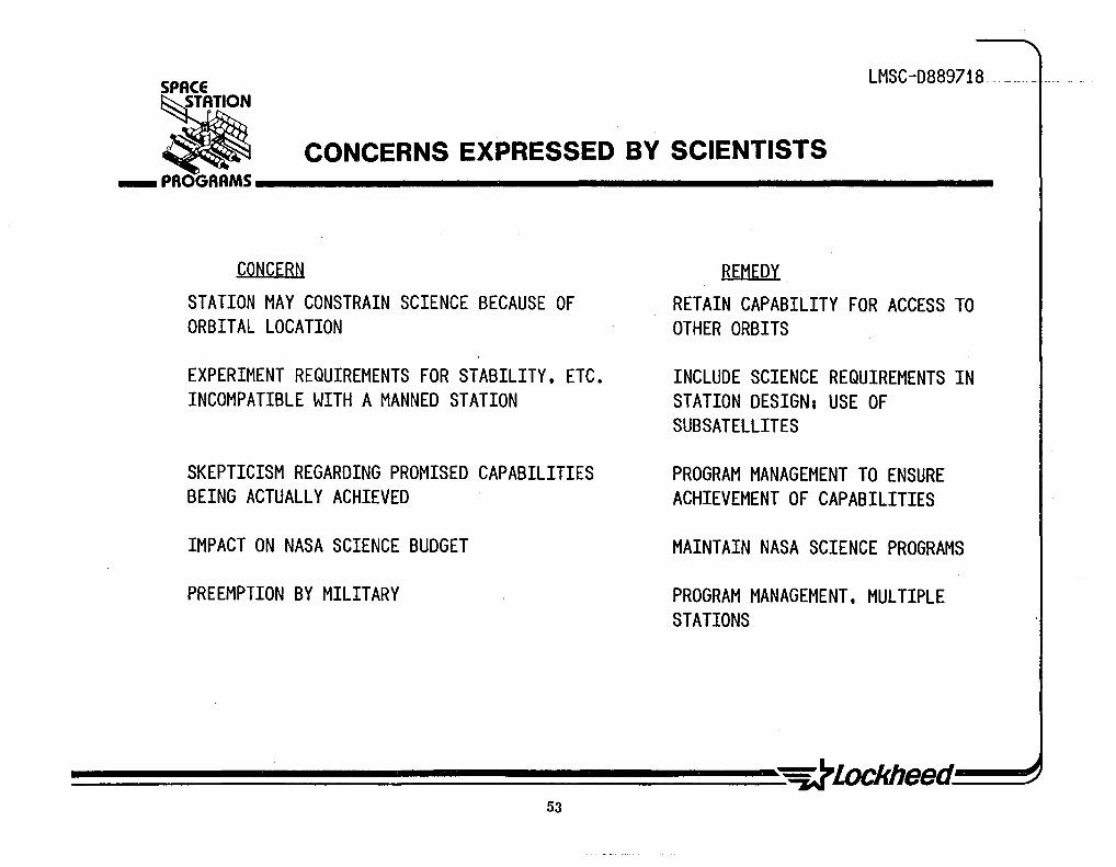
Despite the many benefits of a space station, concerns have been expressed by scientists. The chart lists the major concerns, as well as ways to alleviate them. In general, remedial action consists of program management by NASA Headquarters to ensure that science user needs are met in space station design and implementation.
These scientist-concerns are discussed in more detail in "Space Science Research in the United States,U Office of Technology Assessment Technical Memorandum, September 1982, pp. 12-16.
52
SPACE LMSC-D889718
CONCERNS EXPRESSED BY SCIENTISTS • ___ PROGRAMS __________________________________________________ __
CONCERN
STATION MAY CONSTRAIN SCIENCE BECAUSE OF ORBITAL LOCATION
EXPERIMENT REQUIREMENTS FOR STABILITY. ETC. INCOMPATIBLE WITH A MANNED STATION
SKEPTICISM REGARDING PROMISED CAPABILITIES BEING ACTUALLY ACHIEVED
IMPACT ON NASA SCIENCE BUDGET
PREEMPTION BY MILITARY
53
REMEDY
RETAIN CAPABILITY FOR ACCESS TO OTHER ORBITS
INCLUDE SCIENCE REQUIREMENTS IN STATION DESIGN, USE OF SUBSATELLITES
PROGRAM MANAGEMENT TO ENSURE ACHIEVEMENT OF CAPABILITIES
MAINTAIN NASA SCIENCE PROGRAMS
PROGRAM MANAGEMENT. MULTIPLE STATIONS

LMSC-D889718
CONCLUSIONS
Our assessment of user needs for physical sciences and applications resulted in several general conclusions:
1. Significant benefits can result from use of a space station by scientists. The primary benefits result from: The continuous operations over long time periods; the large structures and high power that will be available; and the manned operation, maintenance and repair of complex systems.
2. Most planned science missions are possible with a space station. Mission requirements identified with the ARTS data base were generally compatible with reasonable space station capabilities and do not seriously constrain space station architecture. The major exceptions are missions with unique orbital requirements (e.g., TOPEX). .
3. The primary scientific benefit of a space station is that it will enable advanced science missions with requirements that now exceed STS capabilities. These missions have large dimensions, great complexity or high power consumption.
54

SPACE LMSC-D889718
• ... PAOGAAMS ____________________________________________________ _ CONCLUSIONS
• A MANNED SPACE STATION CAN BE OF SIGNIFICANT BENEFIT TO THE SCIENTIFIC COMMUNITY
• MANY PLANNED AND APPROVED SCIENCE MISSIONS ARE COMPATIBLE WITH SPACE STATION
• SPACE STATION WILL ALLOW DEVELOPMENT OF SCIENTIFIC SYSTEMS THAT ARE NOW CONSTRAINED BY STS CAPABILITIES
55

________________ ~ ____ A_ ____________________________________ _JA~ ______________________ __

co ..... '" m co co C I
U rn ~ -I
CIJ ~ W 0 Z w -0 CIJ W lL -....J

LMSC-D889718
REASONS FOR RESEARCH IN SPACE
Over the years the goals of the Space Life Sciences Program have been stated in various NASA documents. Among these are:
• Future Directions for the Life Sciences in NASA
• Life Sciences Division -Ten-Year P1an,- July 1982
• Announcement of Opportunity OSS-1-78 Life Sciences Investigations on Space Shutt1e/Space1ab Missions
• Space Sciences and Applications Notice, October 1982
• NASA Program Plans
• Annual NASA Budget Request Documents
The chart opposite is an LMSC composite of these goals statements.
58

SPACE LMSC-D889718
REASONS FOR RESEARCH IN SPACE • ___ PROGRAMS __________________________________________________ __
• TO UNDERSTAND AND MITIGATE THE EFFECTS OF THE SPACE ENVIRONMENT ON HUMANS SO THAT A VARIED SEGMENT OF THE POPULATION CAN PARTICIPATE DIRECTLY IN SPACE FLIGHT
• TO DEVELOP THE FOUNDATION FOR THE EXTENDED PRESENCE OF. AND EXTENDED OPERATION BY. HUMANS IN SPACE
• TO INCREASE MANKIND'S UNDERSTANDING OF THE EFFECTS OF THE UNIQUE SPACE ENVIRONMENT ON BIOLOGICAL PROCESSES
• TO USE THE SPACE ENVIRONMENT TO BETTER UNDERSTAND LIFE PROCESSES ON EARTH • TO UNDERSTAND THE ORIGIN. EVOLUTION. NATURE. AND DISTRIBUTION OF COMPLEX LIFE
IN THE UNIVERSE. AND TO UNDERSTAND ITS INTERACTION WITH THE ENVIRONMENT
59

LMSC-D889718
WHY RESEARCH ON A SPACE STATION
Most Life Sciences research areas require time periods greater than can be provided by Shuttle so that new physiological norms after exposure to zero gravity can be reached. The vestibular system appears to be the only exception, allowing end points to be reached during a Shuttle mission duration.
Current NASA planning calls for approximately three dedicated Life Sciences missions between now and 1991 when a space station would become operational. This results in only 20 to 30 total days on-orbit, which is small in comparison to the large investment. The NASA Life Sciences organization is spending approximately $20M per year, exclusive of launch costs, for a 10 to 15 year period to support this effort.
A 3pace station will provide far more continuous time on orbit and therefore has the potential to be more cost effective than Shuttle in terms of the amount of science gained per day on orbit and per dollar invested in facilities and equipment. The longer stay times also will result in higher quality science due to increased experimenter interaction.
Before man can proceed to the next step in space, which could be a colony or interplanetary exploration, life Sciences research on a space station is required to qualify man for these endeavors and to develop any required countermeasures to the effects of prolonged exposure to zero gravity.
60

SPACE LMSC-D889718
Ii ... PROGRAMS __________________________________________________ __ WHY RESEARCH ON A SPACE STATION
• MOST LIFE SCIENCES RESEARCH REQUIRES LONGER THAN 7-10 DAYS • PLANNED DEDICATED SHUTTLE/SPACELAB TIME BETWEEN NOW AND 1990 IS ONLY
20 TO 30 DAYS TOTAL ON ORBIT
• SPACE STATION PROVIDES CONTINUOUS TIME IN ORBIT • SPACE STATION IS MORE COST EFFECTIVE • LIFE SCIENCES RESEARCH ON SPACE STATION IS REQUIRED TO ENABLE MAN TO
PROGRESS TO NEXT STEP
61

LMSC-D8897l8
EXPERIMENT REQUIREMENTS
In order to identify life sciences user requirements, candidate experiments to be performed on a space station were defined. These candidate experiments are only examples used to extract principles of procedures, equipment, and requirements to ensure that the architecture of the space station will be compatible with the experiment requirements. The list of candidate experiments was developed by using the experiments defined by NASA Headquarters in -Life Sciences Considerations for Space Station- as a starting point and adding to the list.
This was done by interviewing personnel within NASA, the Air Force, universities, research organizations, advisory committees, and other members of the scientific community. During the course of the interviews, the NASA list of experiments was reviewed and ideas for other pertinent experiments solicited. The experiment lists then were analyzed to est~blish characteristics that would impact architecture. These first included general characteristics such as orbit inclination, altitude, and pointing requirements. The experiments were then categorized by discipline category. The species and number of specimens required were established for nonhuman experiments. Priorities were established for the experiments. Crew involvement was assessed and data requirements were estimated •. Experiment-unique hardware also was identified.
The analysis included identification of common life sciences la~oratory equipment required to support all of the candidate experiments. These common items were· identified and cross-referenced against the experiment lists. Development status. of these common equipment items has been defined along with weight, volume, and power estimates. Items of equipment that can be shared between the human and nonhuman research laboratory have been identified.
62

LMSC-D889718 SPACE
EXPERIMENT REQUIREMENTS • ___ PROGRAMS __________________________________________________ __
• • •
EXPERIMENTS IDENTIFIED BY NASA EXPERIMENTS IDENTIFIED BY LOCKHEED SURVEY REQUIREMENTS
- GENERAL PARAMETERS - DISCIPLINE CATEGORY - SPECIES AND NUMBER - PRIORITY - CREW INVOLVEMENT - DATA REQUIREMENTS - EXPERIMENT UNIQUE HARDWARE (WEIGHT, VOLUME, POWER)
• COMMON FACILITY REQUIREMENTS - EXPERIMENTS CROSS REFERENCED - DEVELOPMENT STATUS - CONFIGURATION
63

LMSC-D889718
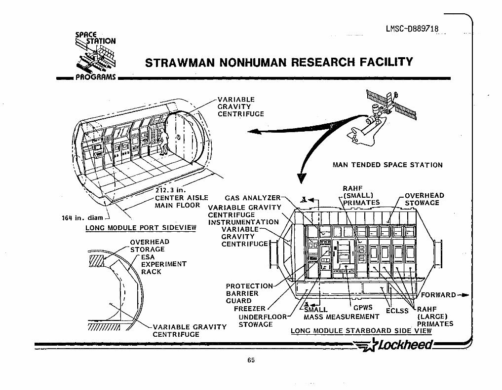
STRAWMAN NONHUMAN RESEARCH FACILITY
The foregoing data provided the basis for the general arrangement of the Strawman Nonhuman Research Facility. This example assumes that the carrier tradeoff indicated use of a Space1ab long module and that maximum use of existing hardware is optimum. A flight system/mission assumption is made in favor of an early manned space station where the onboard crew is involved in the Life Sciences activity only in the event of an equipment malfunction.
Based on the previous data on 90-day vivarium capacities, two rodent, one small primate, and four large-primate single-rack holding facilities would be required in the vivarium portion of the research facility. The centrifuge and the two plant holding facilities also would be located in the vivarium area.
The general arrangement is reponsive to the experiment requirements and allows a smooth workflow with adequate accessibility.
64
SPACE LMSC-D889718
• STRAWMAN NONHUMAN RESEARCH FACILITY ___ PROGAAMS __________________________________________________________ __
VARIABLE GRAVITY CENTRIFUGE
---~~ ~, ~ ,
" _. ~i12.3 in. . . ~ ~- CENTER AISLE GAS ANALYZER
\ MAIN FLOOR VARIABLE GRAVITY
164 in. diam.J . CENTRIFUGE . INSTRUMENTATION
LONG MODULE PORT SIDEVIEW VARIABLE
OVERHEAD STORAGE
ESA EXPERIMENT RACK
GRAVITY CENTRIFUGE
PROTECTION BARRIER GUARD
FREEZER UNDERFLOOR
VARIABl..E GRAVITY STOWAGE CENTRIFUGE
MAN TENDED SPACE STATION
RAHF (LARGE) PRIMATES
LONG MODULE STARBOARD SIDE VIEW
~~~~~~~~~~~~~~~~~~Meed~~ 65

LMSC-D889718
STRAWMAN HUMAN RESEARCH AND HEALTH MAINTENANCE FACILITY (1)
Additional details of this facility are shown in these port and starboard elevations.
66

SPACE
STRA WMAN HUMAN RESEARCH AND HEALTH MAINTENANCE FACILITY (1)
LMSC-D8~9718
• ___ PROGRAMS .. __________________________________________________________ __
LARGE AIRLOCK
• ZERO··C EXP IRESEARCH • SUITED SUBJECT
PARTICIPATION
STORAGE UNITS
+-FWD
STORAGE UNITS PHARMACEUTICALS
DISPENSARY
BEDS/EMERGENCY TREATMENT TABLE
MEDICAL/SURGICAL STORAGE
STARBOARD ELEVATION
PORT ELEVATION
67
TDOLS AND HARDWARE DEMO/EVAL AND RESEARCH STORAGE
EXERCISE. MOBILITY AND LOCOMOTION DEMO/EVALUATORS AREA
PHYSICAL EXERCISE EQUIPIoIENT
LARGE AIRLOCK
• EVA TOOLS/AIDS • EQUIPIoIENT /HARDWARE
HEAVY PARTITION
lERO-G RESTRAINTS (CHAIRS) STOWED
FWD--'

LMSC-D8897l8
ARCHITECTURAL CONSIDERATIONS
The impact of life sciences research on space station architectural considerations is presented for both near-term and long-term situations. Studies to date have concluded that the human research laboratory will evolve from the health maintenance facility, which is justified easily on the basis of the cost of a single r~scue mission.
A nonhuman laboratory is needed to allow invasive and prolonged experiments that cannot be conducted on humans. This facility will be separate from the human research laboratory but attached to the station and will contain a shirt-sleeve environment. The large investment in Spacelab equipment cannot be ignored, therefore, space station hardware will be similar to Spacelab hardware where possible.
Plant experiments may be conducted on free flyers but animal experiments will probably not be •. There is an advantage to free flyers for plant studies because plant physiologists want low gravity, e.g., 10-4 g or less and no disturbances such as crew movements or docking. However, automating an animal experiment to be flown on a free flyer would be extremely costly.
In the long term there are two significant areas where life sciences considerations may have a major impact on the architecture of a space station. These are in the areas of radiation shielding and artificial gravity. A space station at geosynchronous orbit or a space settlement requires considerable shielding to reduce radiation to near terrestrial levels.
The issue of artificial gravity has not been completely laid to rest. The end point of some physiological phenomena such as calcium loss has not been determined and future research may establish that artificial gravity is required. This could have a significant impact on the configuration of a space station.
68

LMSC-D889718 __ .. SPACE
~ ___ PROGRAMS ____________________________________________________ _ ARCHITECTURAL CONSIDERATIONS
NEAR TERM • HUMAN RESEARCH LABORATORY WILL EVOLVE FROM HEALTH MAINTENANCE FACILITY • HEALTH MAINTENANCE FACILITY EASILY JUSTIFIED ON BASIS OF COST OF RESCUE
MISSION • NONHUMAN LABORATORY NEEDED TO ALLOW INVASIVE OR PROLONGED RESEARCH
REQUIRED FOR FURTHER UNDERSTANDING OF BIOLOGICAL EFFECTS OF SPACE
• NONHUMAN LABORATORY WILL BE SEPARATE FROM HABITATION MODULE, BUT ATTACHED TO SPACE STATION
• LARGE INVESTMENT IN SPACE LAB EQUIPMENT CANNOT BE IGNORED • PLANT EXPERIMENTS MAY BE CONDUCTED ON FREE FLYERS, BUT ANIMAL EXPERIMENTS
WILL NOT
FAR TERM • LIFE SCIENCES CONSIDERATIONS COULD BE MAJOR DRIVER ON LONG DURATION
MISSIONS - RADIATION SHIELDING - ARTIFICIAL GRAVITY
69

LMSC-D8897l8
RADIATION ~ONSIDERATIORS, _ . c
The'life science consider'ations relat~edto rad,iation are restricted to crew impacts. The concerns are to assu~~' satisfact~ryc~~w perf6rmance and to, prevent both immediate and late health effects.
There are five main rad,iation h'aia'r'ds'.By far the most dangerous are solar flares, which can r~su1t i~ radiation \~vels ~ear,Earth that are extremely intense and penetra t i ng, and can be 1 etha 1 ." Their occurre'rice -i s unpred i ctab 1 e but generally follows the 11-year solar cyc1~. FiVe to nine events per year can be anticipated~ Ga.1act1c cosmfcrays are 'present' to: 'a 'colony at L-5 or on an interplanetary mission, the radiation levels are higher; ,
. . . ~ - :.
The Earth's magnetic field tra~stcismit radiation in belts (i.e., the Van Allen belts) of varying intensity. At low altitudes the.radlafion varies enormously during an orbit, with peaks occurring over the ~out~'At1ahtfc/South American anomaly. Data must be integrated, ove~ many Drbits tn determine doses.
". r \.:
Calculation of dosage must take into account~an~ factors, including consideration of the body's' abil itt to rep'a'ir som'e :radicitton damage ..
70
LMSC-D889718 . SPACE
RADIATION CONSIDERATIONS • ___ PROGRRMS __________________________________________________ ___
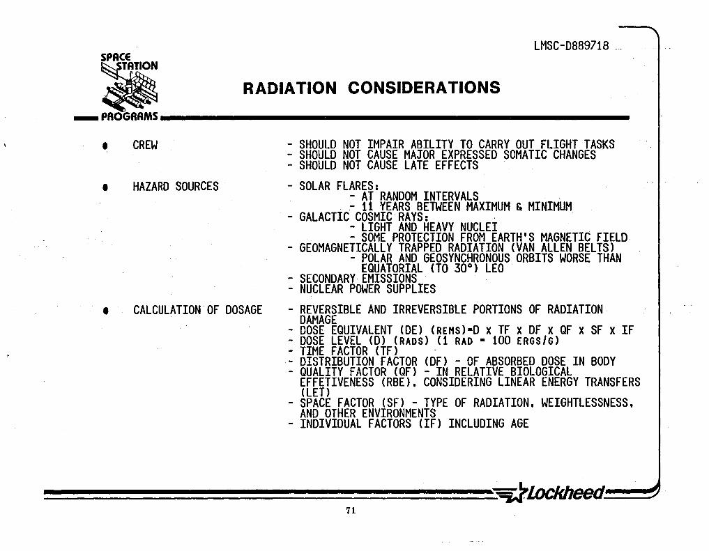
• CREW - SHOULD NOT IMPAIR ABILITY TO CARRY OUT FLIGHT TASKS - SHOULD NOT CAUSE MAJOR EXPRESSED SOMATIC CHANGES - SHOULD NOT CAUSE LATE EFFECTS
• HAZARD SOURCES - SOLAR FLARES: - AT RANDOM INTERVALS - 11 YEARS BETWEEN MAXIMUM & MINIMUM
- GALACTIC COSMIC RAYS: . - LIGHT AND HEAVY NUCLEI - SOME PROTECTION FROM EARTH'S MAGNETIC FIELD
- GEOMAGNETICALLY TRAPPED RADIATION (VAN ALLEN BELTS) - POLAR AND GEOSYNCHRONOUS ORBITS WORSE THAN
EQUATORIAL (TO 30°) LEO - SECONDARY EMISSIONS - NUCLEAR POWER SUPPLIES
• CALCULATION OF DOSAGE - REVERSIBLE AND IRREVERSIBLE PORTIONS OF RADIATION DAMAGE
- DOSE EQUIVALENT (DE) (REHS)-D X TF X DF X QF X SF X IF - DOSE LEVEL (D) (RADS) (1 RAD - 100 ERGS/G) - TIME FACTOR (TF) -- DISTRIBUTION FACTOR (OF) - OF ABSORBED DOSE IN BODY - QUALITY FACTOR (QF) - IN RELATIVE BIOLOGICAL
EFFETIVENESS (RBE). CONSIDERING LINEAR ENERGY TRANSFERS (LET)
- SPACE FACTOR (SF) - TYPE OF RADIATION. WEIGHTLESSNESS. AND OTHER ENVIRONMENTS
- INDIVIDUAL FACTORS (IF) INCLUDING AGE
71

LMSC-D8897l8
RADIATION RECOMMENDATIONS
The effects of radiation on man in space are not known, as can be seen from the widely varying dosage recommendations. Research is needed in space to determine the possible synergistic effects of the unique environments of weightlessness and cosmic/solar radiation, neither of which can be duplicated. on Earth. Extensive monitoring is needed also due to the variabilities in data and models of the environment. Since some studies recommend flare shelters, and flare warnings leave only a short time after detection, prediction techniques would be very useful. Research on drugs for protection or as contermeasures also could produce very cost effective benefits if shielding could be reduced.
Instrumentation development is recommended for both individual and spacecraft monitoring and research studies. Biomedical diagnostic tests of astronaut condition such as via some new urinalysis techniquewotild add to monito~ing capabilities.
R&D in the radiation area is expected to havespin~off benefits in the areas noted.
72
1
LMSC-D889718 SPACE
RADIATION RECOMMENDATIONS :Ii ___ PROGRAMS __________________________________________________ __
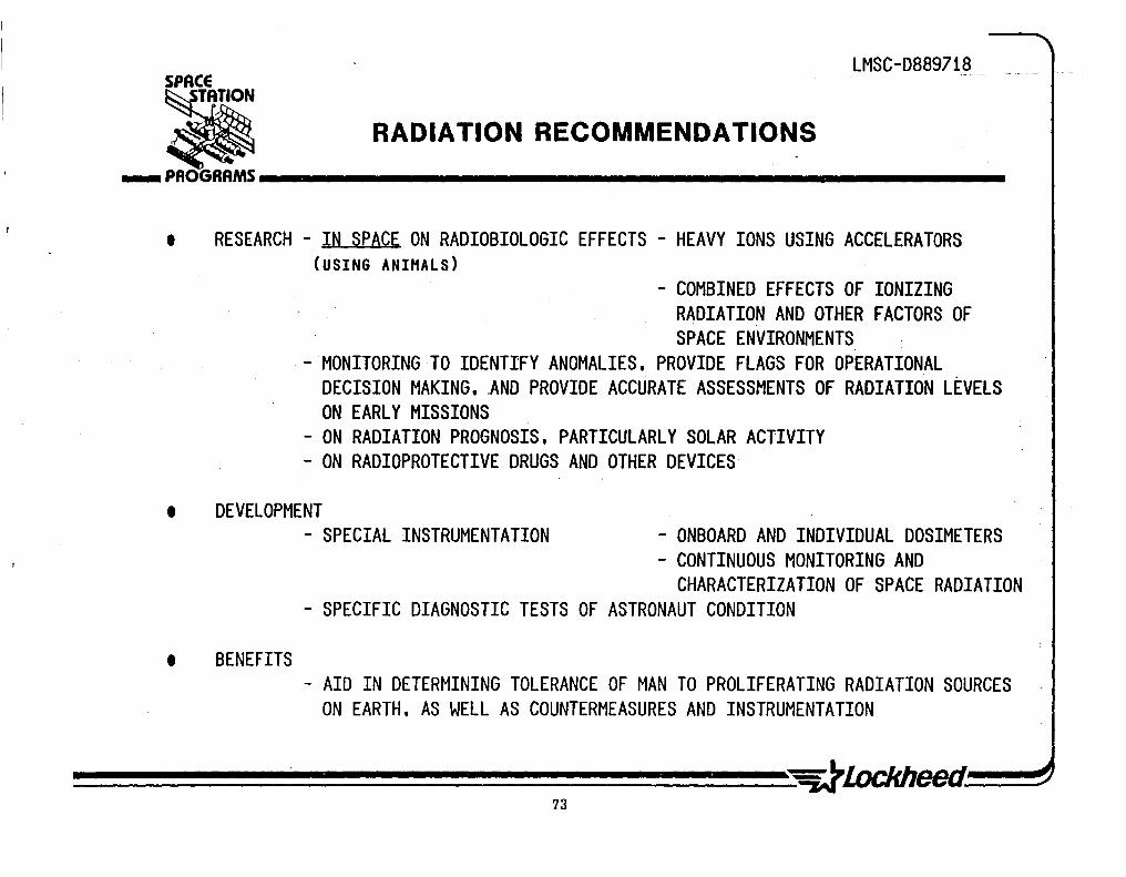
• RESEARCH - IN SPACE ON RADIOBIOLOGIC EFFECTS - HEAVY IONS USING ACCELERATORS (USING ANIMALS)
- COMBINED EFFECTS OF IONIZING RADIATION AND OTHER FACTORS OF SPACE ENVIRONMENTS
- MONITORING TO IDENTIFY ANOMALIES, PROVIDE FLAGS FOR OPERATIONAL DECISION MAKING, .AND PROVIDE ACCURATE ASSESSMENTS OF RADIATION LEVELS ON EARLY MISSIONS
- ON RADIATION PROGNOSIS, PARTICULARLY SOLAR ACTIVITY - ON RADIOPROTECTIVE DRUGS AND OTHER DEVICES
• DEVELOPMENT
• BENEFITS
- SPECIAL INSTRUMENTATION - ONBOARD AND INDIVIDUAL DOSIMETERS - CONTINUOUS MONITORING AND
CHARACTERIZATION OF SPACE RADIATION - SPECIFIC DIAGNOSTIC TESTS OF ASTRONAUT CONDITION
- AID IN DETERMINING TOLERANCE OF MAN TO PROLIFERATING RADIATION SOURCES ON EARTH, AS WELL AS COUNTERMEASURES AND INSTRUMENTATION
73
LMSC-D8897l8
ARTIFICIAL GRAVITY CONSIDERATIONS
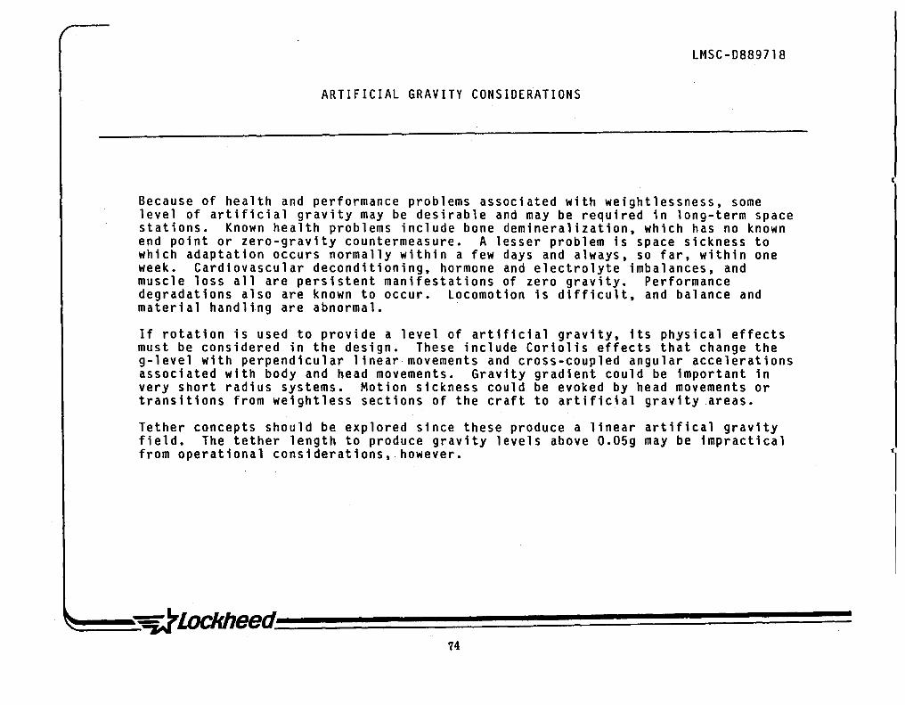
Because of health and performance problems associated with weightlessness, some level of artificial gravity may be desirable and may be required in long-term space stations. Known health problems include bone demineralization, which has no known end pOint or zero-gravity countermeasure. A lesser problem is space sickness to which adaptation occurs normally within a few days and always, so far, within one week. Cardiovascular deconditioning, hormone and electrolyte imbalances, and muscle loss all are persistent manifestations of zero gravity. Performance degradations also are known to occur. Locomotion is difficult, and balance and material handling are abnormal.
If rotation is used to provide a level of artificial gravity, its physical effects must be considered in the design. These include Coriolis effects that change the g-level with perpendicular linear movements and cross-coupled angular accelerations associated with body and head movements. Gravity gradient could be important in very short radius systems. Motion sickness could be evoked by head movements or transitions from weightless sections of the craft to artificial gravity areas.
Tether concepts should be explored since these produce a linear artifical gravity field. The tether length to produce gravity levels above 0.05g may be impractical from operational considerations, however.
74

LMSC-D889718-
ARTIFICIAL GRAVITY CONSIDERATIONS ___ PROGRAMS __________________________________________________ __
• HEALTH PROBLEMS OF NO GRAVITY
• HUMAN PERFORMANCE
• PHYSICAL EFFECTS OF ROTATION
75
BONE DEMINERALIZATION - NO KNOWN END POINT SPACE SICKNESS - ADAPTATION WITHIN ONE WEEK CARDIOVASCULAR DECONDITIONING - PERSISTENT HORMONE AND ELECTROLYTE IMBALANCES -PERSISTENT MUSCULAR ATROPHY - PERSISTENT
SELF LOCOMOTION MATERIAL HANDLING TRANSITION FROM ARTIFICIAL GRAVITY TO WEIGHTLESSNESS POSTURAL BALANCE
CORIOlIS - CROSS COUPLED ANGULAR ACCELERATIONS
- MOTION SICKNESS GRAVITY GRADIENT TETHER CONCEPT AVOIDS THESE PROBLEMS
DESIGN CRITERIA FOR EFFECTIVE HUMAN PERFORMANCE IN ROTATING SPACE STATION
LMSC-D889718
A graphic summary of Thompson's criteria for artificial gravity shows several boundary limits. The vertical lines on the left and right represent the g limits of 0.28 minimum for locomotion and 1.0 for Earth standard. Curves of rotation rate versus g show the 6 rpm ceiling and curves of Corio1is force, Fe, show the 20 percent ceiling. The knee in this chart for minimum radius occurs at 48 feet.
76

SPACE LMSC-D889Z18 ______ _
DESIGN CRITERIA FOR EFFECTIVE HUMAN PERFORMANCE IN ROTATING SPACE STATION • ... PROGRAMS .. ________________________________________________________ __
l-LL ..... Z 0 l-e( I-0 a::: LL 0 til :J
C e( a::: I
UJ ..J U
::I: UJ >
qOOO
20 ECOMMENDED
ZONE FOR EFFECTIVE HUMAN .PERFORMANCE IN ROTATING SPACE
~-c>2 SYSTEMS
q
2~--~--~----~--~----~--~ o 0.2 O.q 0.6 0.8 1.0 1.2
APPARENT GRAVITY ON CREW ("G")
77
z o le( Io a::: UJ ..J U ::I: UJ > LL o UJ le( a:::

LMSC-D8897l8
RECOMMENDATIONS REGARDING ARTIFICIAL GRAVITY
The artificial gravity requirement is very ill-defined at this time. Most investigators feel it is going to be needed, but rotation rates and g-levels are subject to widely differing opinions.
A research program is needed, and must be conducted in the weightless space environment to produce me~ningful results. The major tool for the research is a variable gravity centrifuge. This has been planned by NASA for the dedicated Life Sciences Spacelabs, although no budget authority has been provided to proceed with flight hardware. Information from Spacelab is needed to plan further studies in space station facilities, ultimately leading to a design decision on artificial gravity.
78

LMSC-D889718
RECOMMENDATIONS REGARDING ARTIFICIAL GRAVITY
• RESEARCH IS REQUIRED IN SPACE ON ROTATION RATES HUMAN ADAPTATION. LONG-DURATION
HABITABILITY. TRANSITION EFFECTS BETWEEN ROTATING AND NONROTATING AREAS
G-LEVEL VARIATIONS - ASSOCIATED WITH RADIAL MOVEMENTS -CONTINUOUS AND STEPPED
LOW-G TOLERANCE LONG-TERM PHYSIOLOGICAL EFFECTS OF ZERO AND FRACTIONAL G-LEVELS
• A LARGE-RADIUS RESEARCH CENTRIFUGE SHOULD BE GIVEN URGENT PRIORITY FOR THE SECOND DEDICATED LIFE SCIENCES SPACE LAB (SL-l0) AND SUBSEQUENT FLIGHTS.
• THE SPACE STATION SHOULD INCLUDE CAPABILITY FOR RESEARCH IN ROTATIONAL HYPOGRAVITY. BOTH WITH HUMAN AND NONHUMAN SUBJECTS.
• SYSTEM STUDY AND EXPERIMENTS ARE REQUIRED ON LINEAR ARTIFICAL GRAVITY FIELD <TETHER SYSTEM)'
79

LMSC-08897l8
CONCLUSIONS
The environment of space provides a unique dimension for the study of human, animal, and plant physiology. This will surely result in additional knowledge leading to health and other benefits. A space station life sciences research _ facility is a mandatory step to obtain the answers required for future activities such as interplanetary exploration. One of the more significant research areas to be explored in this respect is defining man's capability in space. Life sciences clearly is one of the justifications for manned activities in space.
80

SPACE LMSC-D889718
• ___ PAOGAAMS __________________________________________________ __ CONCLUSIONS
• SPACE PROVIDES A NEW DIMENSION FOR LIFE SCIENCES RESEARCH
• SPACE STATION IS A MANDATORY STEP TO OBTAIN LIFE SCIENCES ANSWERS FOR FUTURE
• LIFE SCIENCES PROVIDES SIGNIFICANT JUSTIFICATION FOR MANNED ACTIVITIES IN SPACE
81


~ :z « -I I::Q
~ u.. W -I
~ -I « :z
M 00 9
~ :z w ~ :z ....... w <..!)
« C-CI) ....... :I: ~
~VI
o :e - a:: ~ c:c a:: . (!)
~~ 0 a:: VI c:c
~ i

..

U1SC-D889713
-~ PROGRAMS iiiiiiiiiiiiiiiiiiiiiiiiiiiiiiiiiiiiiiiiiiiiiiiiiiiiiiiiiiiiiiiiiiiiiiiiiiiiiiiiiiiiiiiiiiil
TASK 1-MISSION REQUIREMENTS 1.1 USER ALIGNMENT PLAN 1~2 SCIENCE AND APPLICATIONS
- PHYSICAL SCIENCES - LIFE SCIENCES
1.3 COMMERCIAL 1.4 U.S .. NATIONAL SECURITY 1 .. 5 SPACE OPERATIOI\JS 1 .. 6 REQUIREMENTS FROM USER NEEDS 1.7 FOREIGN CONTACTS
VI m n -I
o Z .... w

LMSC-D8897l8
EVOLUTIONARY STRATEGIES AND PROGRAM OPTIONS
Commercial missions have important implications for space station program planning. The task of the system designer is not to specify a definite final design for the space station, but to establish rules which ensure that the various modules or sub-assemblies will work together effectively as a system, while permitting the maximum flexibility in the design of the individual units. In budget planning, the objective is not necessarily to complete the space station (however, that is defined) at minimum cost, but to make the commercial missions economically attractive at the earliest possible date. The goal is to obtain a positive cash-flow with minimum initial investment of money and time, and then to maximize the return on investment. To stimulate development of commercial missions, the objective of the space station studies should not be to pick winners amongst potential technologies, but to create the climate for inn~vation and entrapreneural success. .
The term "space station" often connotes a single, dedicated structure in Earth orbit, but in practice the facility is likely to be an assemblage of loosely coupled or free-flying structures or an "Industrial Park." The space station development program can have clearly-defined milestones, but there will be no specific event signifying completion of the facility. If the project is successful, the station will grow and change for an indefinite period, in ways that are not now predictable: it might remain largely a research facility, it might form the nucleus for industrial projects in Earth orbit, and it might become the staging base for the exploitation of extraterrestrial material and energy resources.
Commercial opportunities in the space station do not consist exclusively of "space applications" i.e., the provision of goods and services for other users of space (commercial or government). For example, a commercial orbital transfer service could be set up to ferry payloads from the space station in low Earth orbit to locations in geosynchronous orbit. Some utility services (power, life support, etc.) aboard the space station could also be developed as commercial ventures.
86
(

LMSC-D889718 SPACE
COMMERCIAL MISSIONS - AN _
AlION
, EVOLUTIONARY STRATEGY ___ PROGRAMS __________________________________________________ _
• IMPLICATIONS OF COMMERCIAL MISSIONS FOR SPACE STATION PROGRAM PLANNING
• THE SPACE STATION AS AN "INDUSTRIAL PARK"
• COMMERCIAL OPPORTUNITIES FOR PROVISION OF GOODS AND SERVICES FOR USE ON EARTH AND FOR OTHER USERS OF SPACE
.• STRATEGY COMPONENTS: PRIVATE SECTOR INVOLVEMENT DESIGN FEATURES COORDINATION REQUIREMENTS
87

LMSC-D8897l8
REASONS FOR COMMERCIAL RESEARCH IN SPACE
The moment has been reached that continuing research on earth to guess how space experiments will come out, is on a deminishing return curve. It is time that a concerted effort is launched to find out what industry needs., what can be done in space, and then perform the experiments to prove they can do what we expect. With this information in hand industry will be more willing to invest and build pilot plants.
88
(
(

LMSC-D889718 SPACE
~ ~ REASONS FOR COMMERCIAL RESEARCH ·IN SPACE ___ ~ROGRAMS __________________________________________________ _
• UNCOUNTED POSSIBLE BENEFITS COULD BE REALIZED
• FEASIBILITY OF SPACE EXPLOITATION HAS TO BE VERIFIED
• MAN's QUEST FOR PROFITS AND CONQUERING FRONTIERS
• NEW INDUSTRY AND SPIN-OFFS WILL IMPROVE ECONOMY AND REDUCE LABOR SURPLUS
• BETTER UNDERSTANDING OF PROCESSES AND THUS POSSIBILITY FOR IMPROVEMENTS ON EARTH' .
89

LMSC-D8897l8
BENEFITS OF SPACE COMMERCIALIZATION
With the tremendous growth of the satellite communication industry still going strong, . proof of space business opportunity is there. Spin-offs from these space ventures
require no proof. Starting with early space exploration a large number of spin-offs have become profitable ventures here on earth.
Space is probably the last remaining frontier and it will certainly yield its secrets as more time is spent in that environment. Commercial opportunities will show ~hemselves in space as the obvious ones already have.
90
t

LMSC-D889718
BENEFITS OF SPACE COMMERCIALIZATION
• COMMUNICATION SATELLITES ALREADY CREATED A NEW INDUSTRY AND SPIN-OFFS
• THE LAST REMAINING FRONTIER-WILL CREATE BUSINESS OPPORTUNITIES REMOTE SENSING (GROWTH) MATERIALS PROCESSING (START) UTILITY· SERVICES (LONG TERM)
91 .

LMSC-D889718
WHY MANNED SPACE STATION-BASED RESEARCH
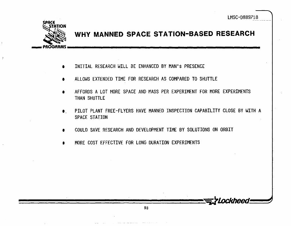
With the opening up of a new frontier, Space based research will become an important force in the drive to total space exploitation. As the results of space research start to come in, more areas for research will be opened, eventually resulting in commercial applications.
Having a space station would greatly enhance those research programs that require long time on orbit. With man avai'lable in space an experiment or research project could have a lower starting cost because of a lesser amount of automation. Man in space can fix problems in operation, data acquisition, and can also change the direction of an experiment without going back to earth.
92
U1SC-D889718
WHY MANNED SPACE STATION-BASED RESEARCH ___ PROGRAMS __________________________________________________ ___
• INITIAL RESEARCH WILL BE ENHANCED BY MAN's PRESENCE
• ALLOWS EXTENDED TIME FOR RESEARCH AS COMPARED TO SHUTTLE
• AFFORDS A LOT MORE SPACE AND MASS PER EXPERIMENT FOR MORE EXPERIMENTS THAN SHUTTLE
" PILOT PLANT FREE-FLYERS HAVE MANNED INSPECTION CAPABILITY CLOSE BY WITH A SPACE STATION
• COULD SAVE RESEARCH AND DEVELOPMENT TIME BY SOLUTIONS ON ORBIT
• MORE COST EFFECTIVE FOR LONG DURATION EXPERIMENTS
93

LMSC-D8897l8
USER SURVEY APPROACH
During the proposal period it was decid~d not to conduct a letter/questionaire campaign because of its extremely low rate of return.
Seminars for selected groups of people were thought to be a more efficient approach. This to be augmented by as many personal telephone contacts followed by multiple visits as would fit time and budget. Presentations to special interest groups, such as the Air Force Materials Lab and Metal Powder Association were another method of reaching large numbers of industries.
94

LMSC-D889718- ---- --
USER SURVEY APPROACH
• SEMINARS WITH FOLLOW-ON VISITS
PERSONAL TELEPHONE CONTACTS WITH MULTIPLE FOLLOW-ON V~SITS
• PRESENTATIONS TO SPECIAL INTEREST GROUPS METAL POWDER ASSOCIATION AIR FORCE MATERIALS LAB
95

LMSC-D8897l8
COMMERCIAL USERS SEMINARS
With these seminars Arthur D. Little/Lockheed planned to contact high level management of carefully selected industries, and through these contacts create a better understanding for space station and its capabilities.
The high technology possibilities and the need to participate in this space venture were highlighted throughout the seminar presentations.
96
fl

LMSC -'D889Z 18_ SPACE
• ... PROGRAMS __________________________________________________ ___ .COMMERCIAL USER'S SEMINARS
A. PURPOSE:
BOSTON SEMINAR 10 NOVEMBER 1982 SAN JOSE SEMINAR 27 JANUARY 1983
• INTERACTION NECESSARY TO GAIN COMMERCIAL HIGH LEVEL MANAGEMENT INVOLVEMENT
• IDENTIFY COMMERCIAL INTEREST
• SOLICIT AND DEMONSTRATE NEED FOR USER INTERACTION. SUPPORT AND HIGH TECHNOLOGY INFUSION
B. EXECUTIVES OF 220 COMMERCIAL ENTERPRISES WERE INVITED TO BOSTON. MASS. AND SAN JOSE. CA.
• 48 ATTENDED FROM BROAD SPECTRUM OF NON-AEROSPACE INDUSTRIES
• A STRONG INTEREST IN SPACE WAS SHOWN
• FOLLOW-UP VISITS WERE MADE ON AN INDIVIDUAL COMPANY BASIS
97

LMSC-D889718
USER SURVEY CONTACT STATISTICS
Various contact approaches were used to attract the commercial community to the space station. The statistics show that with the seminar more people were reached with an initial invitation but the return (efficiency) was only 23%. .
By making direct telephone contacts, although more difficult than getting a letter to a high level officer, the yield improved incredibly. From these contacts came invitations to a trade association officers meeting in Florida. They were in turn interested enough to invite us to set up an Space Station information booth at the Metal Powder Industrjes Federation (MPIF) trade fair (1-4 May 83).
These surveys should be continued and expanded to include flight data exchange, and eventually specific experiments could be performed for the fndustries contacted. This growth process has to proceed any thought of commercialization.
98

LMSC-D889l18.-
USER SURVEY CONTACT STATISTICS
)
METHOD OF CONTACT INVITATIONS ATTENDEES YIELD
SEMINAR 220 50 23%
FOLLOW-ON VISITS 26
TELEPHONE CONTACTS 50 45 90%
FOLLOW-ON VISITS 35
PRESENTATION BY INVITATION (MPIF) FOLLOW-ON REQUEST TO EXHIBIT 12 SPACE STATION AT TRADE FAIR TELEPHONE ARRANGEMENT FOR 5,000 EXHIBIT AT TRADE SHOW (ERA)-
NOTE: COMPLETE LISTING OF CONTACTS PRESENTED IN ATTACHMENT 2
-ELECTRONICS REPRESENTATIVES ASSOCIATION
99

CONCLUSION ON COMMERCIAL CONTACTS
LMSC-D8897l8 PG/OOl
Contacts made for the seminar yielded a lower percentage of attendance than a direct telephone call or letter. The direct telephone and letter approach does cost more time for the person making the contacts, but the yield is high.
In general a lot of interest for space work was instilled in the people contacted. Surprisingly the total knowledge available about space in general and NASA in specific in the commercial areas is rather minimal. More information needs to be relayed to a broader base of industries.
Most people contacted were willing to look into the possibilities for them in space. The problem was that many did not know how and where to start, which is a sign of not knowing what space can do for them •.
100
(,

LMSC-D889718
CONCLUSION ON COMMERCIAL CONTACTS ___ PROGRAMS __________________________________________________ _
• APPRECIABLE INTEREST WAS EXHIBITED BY MAJORIty OF CONTACTS • AGREEMENT THAT THE USA MUST BE FIRST IN HIGH TECHNOLOGY TO WITHSTAND FOREIGN
COMPETITION
• REALIZATION OF THE NEED TO EXPLORE THE PROFITABILITY OF SPACE EXPLOITATION • NUMEROUS QUESTIONS ON HOW SPACE WOULD IMPROVE p,RESENT PROCESSES • REQUESTS TO SHOW IMPROVEMENT POSSIBLE - -SHOW ME A SAMPLE-• SMALL NUMBER HAVE MONEY AVAILABLE HOWEVER. THEY WANT A 5-6 YEAR RETURN • MOST WANT TO BE KEPT INFORMED JUST IN CASE SOMETHING MAY TURN UP • ELECTRONICS AND METAL PROCESSING ARE PROBABLY ABOUT 5 YEARS OFF • PHARMACEUTICALS LOOK PROMISING FOR NEXT 3 YEARS MAINLY BECAUSE OF
ELECTROPHORESIS
• COMMUNICATIONS WILL CONTINUE TO GROW. HOW MUCH SPACE STATION WILL HELP IS. STILL A QUESTION
101 .

LMSC-D889718
POTENTIAL BENEFITS OF COMMERCIAL ACTIVITIES (1)
Telecommunications
The advancement of telec~mmunications will require low launch, assembly, and deployment costs. Interest is growing in the deployment of multi-mission satellites with a mass in the 5000kg range, and platforms with higher power output and onboard processing/switching capabilities. Lower user costs could be achieved by extending satellite life with on-orbit maintenance and repair. The space station could be a control center for satellite transmission, a relay and switching network, and the base for the assembly of platfo~ms for multi-purpose system functions leading to orbital arc and spectrum conservation.
The space station could be used for evaluating new technologies, including satellite system networks for distributed and centralized architectures; multibeam antennas up to 100 meters in diameter; satellite relays; onboard processing and switching capabilities for microwave links, laser links, and modulators and switches; propulsion systems for transfer from low-Earth to geosynchronous orbit for assembly and deployment; control and stationkeeping means to achieve pointing of 0.2 degree beams; and electromagnetic wave propagation for the development of new spectral windows.
The space station represents "waterfront property· because a great value is attached to the desirable orbit positions which are limited in number. The space station could be an integral part of business planning strategies for organizations 1n the telecommunications. field. Such a facility cannot belong to any single industrial organization because the magnitude of the investment would be difficult to justify. Participation in space station activities by industrial organizations active in telecommunications will insure that these companies can expand their commercial activities.
102
POTENTIAL BENEFITS OF COMMERCIAL·ACTIVITIES (1)
LMSC-D889718------ ---
_PROGRAMS _______________________ _
• TELECOMMUNICATIONS
103

LMSC-D8897l8
POTENTIAL BENEFITS OF COMMERCIAL ACTIVITIES (2)
Materials Processing in Space
The scientific benefits of materials processing in space (MPS) which include: reducing buoyancy-driven natural convection, containerless processing, reducing gravity-induced separation of mixtures of materials with different densities, using containment structues that cannot survive on Earth, investigating molecular-level forces in microscopic systems, and testing experimentally the assumptions necessary in theoretical model systems with inherent complicated patterns of fluid density variations are increasingly accepted.
The commercial benefits, of MPS have to be demonstrated in future shuttle experiments to gui~e such activities in a space station. These benefits are projected to include: advances in the science and technology of materials processing; the demonstration of products with unique and valuable properties as a spur to the development of terrestrial alternative production methods; and the production of unique materials and products that could lead to a future space-based materials processing industry. At present, the most promising commercial applications of MPS include pharmaceuticals, electonic materials, glasses, .and metal alloys and composites.
The most likely role for a space station in MPS is as a national laboratory for R&D. The space station is the only planned opportunity for U.S. industry to demonstrate MPS potential for commercial production, and to close the information gap between the U.S. and the USSR in MPS.
104

POTENTIAL BENEFITS OF COMMERCIAL ACTIVITIES (2)
LMSC-D889718 -- - -
_PROGRAMS _______________________ _
• MATERIALS PROCESSIN&

LMSC-D8897l8
POTENTIAL BENEFITS OF COMMERCIAL ACTIVITIES (3)
Utility Services
Incentives for industry participation in commercial activities could be provided by utility services supplied to space station users. If NASA, or an appropriate federal agency created for this purpose, would provide long-term guarantees and service contracts, companies might be interested in providing facilities and services charged to the users in ways analogous to similar services provided in terrestrial industrial facilities. Examples of such utility services are power supplies; housekeeping and life support including equipment, consumables, and waste mangement; habitability features, including crew accomodations, recreational facilities and food preparation and service; medical and health care; personnel services including crew selection and training and contract p~rsonnel; rent or sale of standard modules that may be attached to a space station structures, ahd free-flying carriers; engineering, consulting, design, and fabricati'on; temperature control of experiments and processing systems; telecommunictions and data handling; operation of earth-to-orbit and orbital transfer, manned or unmanned, transportation systems and on-orbit refueling facilities for such systems.
NASAls and other federal agencies function would be to assure that the facilities and services provided to a space station meet the userls needs, that they are well integrated with the space station requirements, and that they meet necessary performance and safety criteria. The return on industry investments to provide commercial facilities and services would be negotiated between participants in space station commercial activities in a competitive environment, with industry taking the lead to develo~~ and provide ~he necessary facilities and sErvices on a business basis. These commercial activities" could be planned from a modest and embryonic start to encompass future"major investment in space industrialization regulated by both U.S. and international space commerce agencies.

POTENTIAL BENEFITS OF COMMERCIAL ACTIVITIES (3)
• UTILITY SERVICES
107
LMSC-D889718-

lMSC-D889718
MATERIAL PROCESSING IN SPACE (1)
Very little materials processing has been done in space in the past. Data in this area has to come from experiments planned for flight in the coming years. Specific industries should be researched and experiments with their specialized requirements in mind should be conducted. The positive results of these experiments will draw the commercial interest that has been lacking so far.
Industrial capital investors want to know what their return will be and when, against what probability of success. This means that what we want to do in space has to be well defined when presenting it.
108
LMSC-D889718 SPACE
• ___ PAOGAAMS __________________________________________________ ___ MATERIAL PROCESSING IN SPACE (1)
AMERICAN ACTIVITY
• NASA COMMITMENT FOR MPS EFFORT HAS NOT INCREASED SIGNIFICANTLY (ABOUT $20M)
• EXPERIMENTERS MAINLY DRAWN FROM NASA, UNIVERSITIES, RESEARCH INSTITUTES, AND AEROSPACE COMPANIES
• TRUE COMMERICAL PARTICIPATION NOTABLE BY ITS ABSENCE (SAME IN OTHER COUNTRIES)
NQI£: EXCEPTION - MDAC/JOHNSON & JOHNSON
• NASA STUDY CONTRACTS DESIGNED TO INVOLVE AND DRAW IN THE COMMERCIAL INTEREST
• STATION ARCHITECTURE AND COSTING ACTIVITIES IN PROGRESS

LMSC-D8897l8
MATERIAL PROCESSING IN SPACE (2)
The activity in Europe is based on the use of Shuttle for their space material processing effort. In some technology areas the fact that a number of the "sciences" were called upon to study and plan a space experiment, already has borne fruit for processes here on earth. This proves that a carefully planned operation is required to get industry and the sciences together to find ways to use space but also to do things better here and now.
110

LMSC-D889718 SPACE
• ___ PROGRAMS __________________________________________________ ___ MATERIAL PROCESSING IN SPACE (2)
EUROPEAN ACTIVITY
• EFFORT IS PARTIALLY DRIVEN BY ESA BUT ALSO ON A NATIONAL BASIS
• ROCKET FLIGHTS STILL PROMINENT IN RESEARCH EFFORT
• NUMEROUS EXPERIMENTS PLANNED WITH SHUTTLE - SPACE LAB. SPAS. EURECA
• SPACE STATION STUDIES IN PROGRESS
• BUDGETARY AND POLITICAL PRESSURES MAKE FOR CAREFUL PLANNING
111

LMSC-D8897l8
MATERIAL PROCESSING IN SPACE (3)
The Japanese are presently spending a rather small amount of money in space research specifically in the area of material processing in space. Their forte lies in the area of electronics and robotics and here they are putting forth a sizable effort.
Their efforts in material processing although low level, may have borne them some fruit namely a hardness in metal that cannot today be explained. However, it is these type of happenings that make a new frontier exciting.
112

LMSC-D889718
MATERIAL PROCESSING IN SPACE (3)
JAPANESE ACTIVITY
• DEVELOPMENT AND EFFORT PROCEEDING TO BUDGET AND SCHEDULE
• MPS EFFORT IS NOT PROMINENT IN JAPANESE PLANNING - COMMUNICATIONS AND ELECTRONIC RELATED ACTIVITIES ARE
• PERFORMANCE OF SOUNDING ROCKETS (TT-SOOA) FOR EXPERIMENTS
• FLIGHTS PLANNED ON SHUTTLE (JAPAN T&T CORP)
• JAPAN SO FAR UNWILLING TO TAKE THE BIG (EXPENSIVE) SPACE LEAP
• CONCENTRATE ON PUTTING HUMAN'S INTELLIGENCE INTO A MACHINE FOR SPACE EXPLOITATION (ROBOTICS)
113

LMSC-D8897l8
MATERIAL PROCESSING IN SPACE (4)
The Russians have to date expended the largest effort in space station related work and probably have performed more experiments in areas ranging from human behavior to material processing. Of course not having complete information about all they did, leaves many unanswered questions. Apparently the opinions that existed earlier about the good work they have done are now changing to the negative direction.
All in all, they have a station and we have not. Hopefully, this will change in the not too distant future.
114

LMSC-D889718
MATERIAL PROCESSING IN SPACE (4)
RUSSIAN ACTIVITY
• CONDUCTING MANY EXPERIMENTS IN SALYUT 6/SALYUT 7 SPACE STATIONS
• ALLOY AND CRYSTAL EXPERIMENTS - REFERENCE TO CADMIUM-MERCURY-TELLURIDE
• LACKS COMMERCIAL COMPONENT
• APPARENTLY THEY SPEND MORE ON RESEARCH THAN USA
• POSITIVE OPINIONS OF IMPRESSIVE WORK IN EARLY TIMES NOW SEEN TO SHIFT TO DOUBTS
• MORE AGGRESSIVE APPEARING SPACE POLICY THAN USA
• EMPHASIS ON NEW ORBITAL STATIONS AS A STEP TO SPACE LASERS

LMSC-D8897l8
COMMERCIALIZATION OF FUTURE ACTIVITIES IN SPACE
A number of potential activities for commercial activities in space are presented. The timing for commercialization for most is probable in the coming decade, some of the presently less obvious possibilities could come at a later date. Although the list contains areas that seem highly improbable at present, we have still left these without giving them a lot of attention. One of these areas is medical services, which on present impulse should be withdrawn however, early withdrawal may not be prudent. Drugs and alloys may offer the best possibilities and should be vigorously pursued. Sensors are of course already in wide use but there use and sophistication will improve many fold during the next decade with long term space research.
116

SPACE
COMMERCIALIZATION OF FUTURE ACTIVITIES IN SPACE
LMSC-D889718
• ___ PROGRAMS __________________________________________________ ___
TIMING FOR COMMERCIALIZATION APPLICATION INDUSTRY SECTOR PARTICIPANTS
1985 - '95 DRUGS PHARMACEUTICALS RESEARCH EQUIP. VENDORS DRUG FIRMS PROCESS EQUIP. VENDORS
1985 - '95 ALLOYS METALS RESEARCH EQUIP. VENDORS 1985 - '95 SEMICONDUCTORS ELECTRONICS ELECTRONIC FIRMS
EQUIPMENT VENDORS 1985 - '95 SENSORS AEROSPACE AEROSPACE FIRMS 1985 - '95 TELECOMM. PLATFORMS COMMUNICATIONS ELECTRONICS
AEROSPACE EQUIPMENT VENDORS
1990 - 2000 MEDICAL SERVICES HEALTH CARE DOCTORS' ORGANIZATIONS HOSPITAL ORGANIZATIONS
1990-- 2000 FACILITY CONSTRUCTION CONSTRUCTION A&E FIRMS EQUIPMENT VENDORS
1985 - 2000 UTILITY SERVICES MANUFACTURING AEROSPACE EQUIPMENT VENDORS
117

LMSC-D8897l8
CHALLENGES TO COMMERCIAL ACTIVITIES
With the increasing attention given to space station and space exploitation, also on the international scene, it becomes more important to focus on the legal aspects for this new and lost frontier. Maybe a "Law of Space" similar to the "Law of the Seas" should be investigated. The third nations that are presently not in a military nor in an economic position to involve themselves with space, are stirring up a move of participation and evan national ownership of space.
Some other issues will have to deal with in the very near future, they are the federal regulations that will control the total space operation.
On a more direct basis, the NASA interface with the commercial world has to be looked at. It may be too early to suggest that there be no direct interface but rather an aerospace company buffer between NASA and commercial enterprises.
118

LMSC-D88971
CHALLENGES TO COMMERCIAL ACTIVITIES ___ PROGRAMS __________________________________________________ _
LEGAL AND REGULATORY ISSUES
OWNERSHIP OF EXTRATERRESTRIAL RESOURCES PROTECTION OF PROPRIETARY RIGHTS ANTITRUST CONFLICTS
INTERFACES WITH FEDERAL GOVERNMENT
REGULATIONS INTERFERENCE WITH OPERATIONS ACCOUNTABILITY LIABILITY COMMUNICATIONS
POTENTIAL CONFLICT WITH 000 ACTIVITIES

CHALLENGES TO COMMERCIAL ACTIVITIES (CONTINUED)
LMSC-D8897l8
To continue with the challenges, we also have to commence with the development of supporting technologies. It is presently well understood that a system is required for transportation between space station components of personnel, equipment, and·material.
For metallurgical processes we know that large amounts of power will be required.
With the orbit crowding of communication satellites we eventually will have to go to narrow beams which means larger antennas and more power, translating into the need for larger satellites. This would indicate the need for orbital staging area and methods of construction and checkout 1n space.
With the long lead times required for this type of effort a timely start will be beneficial.
120

LMSC-D889718 SPACE
.
~ .. ~~AnON ~ CHALLENGES TO COMMERCIAL ACTIVITIES (CONT) ___ PROGRAMS ________________________________________________ __
AVAILABILITY OF SUPPORTING TECHNOLOGIES
SPACE TRANSPORATION SYSTEM ORBITAL TRANSFER VEHICLES OPERATIONAL FACILITIES POWER SUPPLY
LEAD TIMES TO DEVELOP COMMERCIAL OPERATIONS
NASA/INDUSTRY JOINT VENTURES GOVERNMENT CONTROL OF ACCESS TO SPACE
121

LMSC-D8897l8
CONCLUSIONS
These conclusions about space commercialization were based on the contacts made with numerous industy representatives and the comments they made.
We also concluded that an important aspect of the user alignment plan is the personal contact approach where an open information exchange is possible.
122

LMSC-D889718 SPACE
:ii _~R~RAMS CONCLUSIONS
.• COMMERCIAL FIRMS GENERALLY UNINFORMED ABOUT SPACE POSSIBILITIES AND ACCESS
• COMMERCIAL FIRMS VERY EAGER FOR COMPREHENSIVE INFORMATION (TECHNICAL AND STATE OF FOREIGN INVOLVEMENT AND PROGRESS)
• VERY FEW CONCRETE COMMERCIAL OPPORTUNITIES HAVE THUS FAR BEEN IDENTIFIED
• DATA BASE OF SPACE PHENOMENA INCOMPLETE
• MULTIPLE IN-DEPTH PERSONAL CONTACTS APPEAR MOST EFFECTIVE IN RELAYING DATA AND BUILDING CONFIDENCE
123

LMSC-D8897l8
RECOMMENDATIONS
The recommendations shown on the figure speak for themselves and ar~ based on the trials and tribulations of the alignment plan activity.
The lack of solid information of direct interest to a potential user is hard to overcome. Therefore, we stress the point that obtaining this type of data/information is of the utmost importance.
Furthermore, it would be a waste to drop all contact with these peop1a at this time. A method to continue these visits should be created. From past experience we know that after creating the interest, a long time gap will cause loss of momentum which can turn an enthusiast to a side-liner.
124
SPACE ~" ~TATION ~ RECOMMENDATIONS
LMSC-D889718
___ PROGRAMS __________________________________________________ ___
• MORE ADEQUATE WRITTEN INFORMATION ESPECIALLY FOR BUSINESS COMMUNITY TO BE MADE AVAILABLE-
• -IN-DEPTH PERSONAL CONTACTS TO BE CONTINUED
• DATA BASE OF SPACE PHYSICAL PHENOMENA SHOULD BE EXPANDED BY NASA
• CONTACTS WITH INDUSTRIES VIA TRADE SHOWS AND OTHER LIKE MEANS TO BE FURTHER EXPLORED
125


SPACE
~ ~ PROGRAMS iiiiiiiiiiiiiiiiiiiiiiiiiiiiiiiiiiiiiiiiiiiiiiiiiiiiiiiiiiiiiiiiiiiiiiiiiiiiiiiiiiiiiiiiiiiiiiil
TASK 1-MISSION REQUIREMENTS 1.1 USER ALIG N M ENT PLAN 1.2 SCIENCE AND APPLICATIONS
- PHYSICAL SCIENCES - LIFE SCIENCES
1.3 COMMERCIAL 1.4 U.S. NATIONAL SECURITY 1.5 SPACE OPERATIONS 1.6 REQUIREMENTS FROM USER NEEDS 1.7 FOREIGN CONTACTS
(/) m
---0--- - - --f o z .... . .:::

LMSC-D889718
FUTURE MILITARY MISSIONS
·The figure on the opposite page was taken from an article in the American Institute of Aeronautics and Astronautics journal dated 14 January 1981 and modified to introduce MILSTAR as an example. This chart was not intended to be related to manned space activity. It was developed to identify those missions to be pursued by 000 in the future for U.S. national security reasons. For the most part these missions represent improvements of existing satellite systems. In some cases the proposed systems incorporate revolutionary technology advances projected to be available in the 1990s.
The purpose of examining this chart in the present study is to identify existing military missions that could potentially benefit from the presence of a manned space station. The primary use of the manned station for these missions is in a supporting role. The station could provide a base for developing and evaluating technology and could also provide the necessary base for assembly of large antenna or other large unmanned satellites. Our analysis of these missions did not suggest replacement of an unmanned satellite by a manned system, however.
128

SPACE LMSC-D889718_ .
~ ~ FUTURE MILITARY MISSIONS *
___ PROGRAMS __________________________________________________________ __
1985 1890 1885 2000
55UPRAVC[EILOfI..JN(E[[' -- ;:~ j I.)'l ., U\ \ ....... '" fiR, a-.. HADAR IALlISfiC J: ....
r. MISSILE -
JI' 08SERVAJlOH
MOSAIC ~ AlMOSPllrRIC AOAPIIV[ MAIHO •. SENSOR _ .,~ SURVElllANC[ OPIICS Slt"OO
OMSP C~,:. ~-:...---->.j;CJ--..;.~+------(f-.O+;,.....;.. ... i~~:;~;"'''AG( ~ ' / : .\;.... CEO-SAl ._. _ .\ .-.. / Jr. OlIO/CIVILIAN
• ~IROH '~~.,: J\ IMPROVED OMSP -COHIlHU S SURVfliiAHcl~ -REAL JlME (ADOUr ( I" MONIIORIr-
.... "('~l\OSCS" /;,~. OSC III ~' .: ... :~. IAm~ ~. l}" - '3-", ., 'UJlII-PURPOSE MAHA';[M(Nf . . ,. ~ ~M~l~ABlE.· '6~) "f~ f X[OlMOlllE I CDMMUHICAnOH
flISAI • ("llSTAR)" ~. ~ SUBAIAIIU' ~ ______ ~~~ ____________ ~~ C~'
TRANSIT W; --IMPROvtMlNI I V ~
PROGRAM GlOBAL r~ POSIIIONING ..r'w r SVSIlM
NAviGATION
129
Il If ADVANCED GPS ANO (iJ COMMANOltONIROt.
uellCAl SUPPlEMENI
lARGO lOCAflOH
* AIAA 14 JAN 81

EVALUATION OF THE SPACE STATION ROLE IN SUPPORTING EXISTING SATELLITE SYSTEMS
LMSC-D889718
The presence of a space station will not create new military missions, but rather will provide a' new means for accomplishing existing missions. For this reason it seemed appropriate to review 18 existing systems to determine if the presence of a space station would influence the ways in which these missions are performed.
The space station could provide a base for data reduction and analysis of information from remote satellites prior to transmitting the information to the ground. In this role it is possible that the station could augment the performance of existing systems. There is substantial diversity of opinion on whether or not this is a valid role for a manned system, however, and there is no identified support at this time to propose this role, as a primary operational requirement for a manned space station. There is considerable interest in evaluating the potential capability for man's involvement in
. this role but s~rictly as a research and development activity.
There is substantial agreement that the manned space station would provide an excellent research and development platform,for check out and evaluation of new components as well as satellite systems. In that sense the RDT&E column on the facing page chart is intended to show the benefit in using the space based platform for development of the next generation of an existing satellite system.
Satellite servicing activities, which comprise the seven remaining columns on the chart, are clearly an accepted and significant function of the space station. It must be emphasized that satellites must be specifically designed for the repair, assembly, resupply, change out, and reconfiguration activities. Existing systems, for the most part, are not designed for space-based support. By the early 1990s, however, new generations of satellites will be launched and these should be designed for space-based satellite servicing. The role of the space station in supporting systems of this type is discussed in the next session titled Space Operations.
130

.. POTENTIAL MILIT ARV APPLICATIONS OF THE SPACE STATION
LMSC-D889718
___ PROGRAMS __________________________________________________________ __
SATELLITE MUST BE SPECIFICALLY DESIGNED FOR THESE OPERATIONS
AUGMENT ASSEMBLE I CHANGE- RECON- DEPLOY I SYSTEMS PERFORM- RDHE REPAIR OBSERVE RETRIEVE ANCE RESUPPLY OUT FIGURE RECONSTITUTE
DSP X X
AWS X X
GPS X X X X
IONDS X X X
DMSP X X X X X X
GEODSS X X
OS] X X X X X X X X
NAVSPASUR X X
HOE ADVANCE SENSOR X X X X X- X X X X
PAVE PAWS X X
SPASER X X X X X X X
AFSATCOM X X
SPACE CRUISER X X X X X X X X X
SCF/CSOC X
SCS X X
SHUTTLE X X X X X X X X
ELVs X
ADVANCED MILITARY X X X X X X X SPACECRAFT
131

LMSC-D889718
MILITARY B(NEFITS OF A SPACE STATION
There is general agreement that there are three primary areas of potential military benefits from a manned space station. Research and development missions offer the most immediate promise for beneficial return. Programs that require evaluation on orbit will benefit by the extended mission duration compared with the time available from the space shuttle. An example of such a program is Talon Gold, which can perform its mission in the 5-day shuttle flight but could realize potentially substantial additional information with a 15 day or more flight. A second program that clearly benefits from extended duration on orbit is the Navy oceanographic sensor development activity that will be discussed further in the following pages.
A second category for which a space station might benefit military uses of space is in the logistics and resupply of satellite systems. The refueling, modification, maintenance and repair, and large structures assembly are all tasks that will play key roles in satellite servicing activities. For the most part satellites must be specifically designed to take advantage of servicing capabilities, and most existing systems will not benefit from satellite servicing operations. By the time a space station is operational, however, a new generation of satellites will be in orbit and if. these are properly designed, space-based satellites servicil1g can play an important role. It is important to evaluate space-shuttle-based servicing compared to space-station-based servicing, however, because of the constraints imposed by orbit mechanics that limit the frequency of revisit opportunities from a space station to specific satellites.
The direct involvement of a space station in operational missions is perhaps the most important, and least well defined, area for potential military benefits of a manned system. Although research and development missions and logistics and resupply missions will make use of a station if it is there, it is unlikely that requirements in these categories will provide a compelling reason for proceeding with a space station. Operational missions, on the other hand, can form a major incentive to proceed with space station development and for that reason these missions are of prime interest. It is possible that the command and control mission for the space station may provide a compelling reason to proceed with the initial phases of space station evolution~
132

SPACE LMSC-D889718
• ___ PROGRAMS __________________________________________________ ___ MILITARY BENEFITS OF SPACE STATION
• RESEARCH AND DEVELOPMENT MISSIONS o IMPROVED PROGRAM PERFORMANCE WIT~ LONGER TIME IN ORBIT.
E.G •• TALON GOLD o SENSOR DEVELOPMENT - MANNED INTERACTION DURING TEST.
E.G •• NAVY OCEANOGRAPHIC SYSTEMS
• LOGISTICS AND RESUPPLY o E.G •• REFUEL ATTITUDE CONTROL. MANEUVER PROPELLANTS.
SATELLITE SERVICING (MAINTENANCE AND REPAIR) ON ORBIT. AND LARGE STRUCTURES ASSEMBLY
o NEED TO EVALUATE SHUTTLE VS. SPACE STATION
• OPERATIONS o COMMAND AND CONTROL.
E.G •• EXTENSION OF NATIONAL MILITARY COMMAND SYSTEM o SPACE OBSERVATION
133

________________________________________ ~~ ___________________________________________ ~~ ____ _A __________________ __

U~SC-D889718
U. S. NATIONAL SECURITY
R&D MISSION SCENARIO
OCEANOGRAPHIC OBSERVATORY DEVELOPMENT LABORATORY

LMSC-D8897l8
OCEANOGRAPHIC OBSERVATORY DEVELOPMENT LAB MISSION SCENARIO
Personnel in the U.S. Navy have expressed considerable interest in expanding existing capabilities for surveillance of the oceanographic characteristics of the high seas. They have found that manned observation from the Apollo, Skylab, and most recently Shuttle orbiter have provided data that cannot be obtained from data recorded by remote sensors. The strong feeling is that once we understand the phenomena being observed by the unaided eye of the astronaut, we will be able to develop remote sensors or interpret the signal of existing sensors, and subsequently implement an unmanned system to detect the features of interest. Thus, the objective here is to use a combination of manned observation and remote sensor data simultaneously to establish the correlation necessary to select operational remote-sensing designs. It is presumed that manned involvement from space is required during the development phase only and that the operational phase will function in a conventional manner such as LandSat or Se?Sat.
This mission is especially well suited to a space station because it combines two key elements: the requirement for manned observation and involvement in space, and the need for an extended period on orbit. Oceanographic phenomena of interest changes slowly with time and it is necessary to make measurements over a period of months in order to obtain the desired data on characteristics such as thermoclines or the presence or absence of long-wave-length deep ocean waves. The change in the characteristics of these features with time is also of particular interest. Though Shuttle-based observations have been helpful in demonstrating the need for visual observation by man in space, the flight duration is too short to provide the scope of data required for this development activity.
136
f

SPACE LMSC-D889718
OCEANOGRAPHIC OBSERVATORY DEVELOPMENT LAB MISSION SCENARIO • ___ PftOGftAMS __________________________________________________ _
MISSION CATEGORY: u.s. NATIONAL SECURITY SYSTEM/PROGRAM: OCEANOGRAPHIC OBSERVATORY DEVELOPMENT LABORATORY OBJECTIVE: .
• TO DEVELOP MULTISENSOR SYSTEMS AND EXPAND EXISTING CAPABILITIES • TO PROVIDE MEANS FOR EXTENDED REALTIME OBSERVATION OF DYNAMIC OCEAN PHENOMENA
AND CONTROL OF SENSOR POINTING AND DUTY CYCLES . I. TO CORRELATE VISUAL OBSERVATIONS IN SPACE AND DATA FROM VARIOUS SENSORS I • TO PROVIDE MEANS TO REDUCE DEVELOPMENT COSTS AND TO MINIMIZE DEVELOPMENT SPANS
BY MAKING USE OF MANNED CAPABILITIES • TO PROVIDE DATA TO EVALUATE ROLE OF MAN IN AN OPERATIONAL ENVIRONMENT
SYSTEM DESCRIPTION: I LIFETIME:
LAUNCH VEHICLE: TRANSFER VEHICLE:
OPERATIONAL LOCATIONS:
3 TO 6 MONTHS PER EXPERIMENTAL SEQUENCEI 10 YEAR USEFUL OPERATION SHUTTLE NONE REQUIRED FOR PAYLOADS HARD-DOCKED ON SPACE STATION TMS REQUUIRED FOR CLUSTER FREE FLYER 300 - 700 KM AT 65 DEGREES PREFERRED 300 KM AT 28.5 DEGREES USEFUL

OCEANOGRAPHIC OBSERVATION DEVELOPMENT LAB (CONT)
LMSC-08897l8
The essence of this development lab scenario is that equipment will be repositioned, modified, or changed out while on orbit in order to assess the effect of the equipment location, pOinting angle or configuration on remote sensor data. It is vital to provide the correlation with manned observation from space made from the identical position and at the same time. Thus the instruments must be located onboard the spacecraft with the astronaut making the observations. Another aspect of this development lab concept is that experimental (brassboard) sensors can be evaluated and this offers the potential of greatly reducing the time for taking laboratory concepts through the development cycle to operational configurations.
The size of the crew necessary to do the development work depends upon the type and complexity of equipment change and modifications anticipated on orbit.
138

LMSC-D889718 SPACE
OCEANOGRAPHIC OBSERVATORY DEVELOPMENT LAB MISSION SCENARIO (CONT) • ___ PROGRAMS __________________________________________________ _
SYSTEM DESCRIPTION: (CONT) TOTAL MASS AT OPERATIONAL LOCATIONS: AVERAGE OPERATIONAL POWER: DESIRED INITIAL OPERATIONAL DATE:
GENERAL NEEDS:
TBD (BUT LESS THAN 14.000 KG) TBD· (BUT LESS THAN 5 KW) 1988 (SHUTTLE-BASED EXPERIMENTS) 1990 (SPACE-STATION-BASED EXPERIMENTS)
• EQUIPMENT TO BE MOUNTED ON EXISTING PALLET (E.G .• ESS OR SPACELAB PALLET)
• ABOR T R S T BE CAPABLE OF SUPP R IN EXPERIMENTAL (BRASSBOARD) HARDWARE AND SENSORS
• PHYSICAL CHARACTERISTICS: 30FT X 14 FT DIAMETER UP TO 40FT ANTENNA (SORTIE) EXPANDABLE OR UNFOLDABLE UP TO 300FT ANTENNA (FREE FLYER)
• OPERATIONAL CREW: 2 EXPERIMENTERS MINIMUM (NO EQUIPMENT MODS) 10 MAN CREW (TECHNICIANS)
• DATA: ONBOARD DATA PROCESSING. 103 HBPS
139

OCEANOGRAPHIC OBSERVATORY DEVELOPMENT LAB (CONT)
LMSC-D8897l8
Sensor architecture should be designed to provide equipment to cover the entire ultraviolet to microwave range of radiation of interest. Sensors exist for all of these categories, but it is the design detail, the sensor size and orientation, and the combination of sensors on a single platform that are critical to this experiment. All of these features can be assessed from a sensor platform attached to the space station. The sensors could be attached to a pallet (or pair of pallets), compatible with the shuttle payload bay, and then transferred with the pallet(s) to a payload 'support fixture on board the space station. If a specific sensor design is incompatible with other sensors on the same payload (for instance a very large SAR antenna that blocks the field of view of an infraed detector), seperate pallets could be used, perhaps even located on different areas of the space station. This still achieves the objective of making simultaneous measurements and comparing those with visual observations.

SPRCE LMSC-D889718
~TRTION
OCEANOGRAPHIC OBSERVATORY DEVELOPMENT o LAB MISSION SCENARIO (CONT) ___ PROGRRMS ________________________________________________ __
SENSOR ARCHITECTURE: • SENSORS OPERATE OVER COMPLETE WAVE LENGTH SPECTRUM
UL TRAVIOLET VISIBLE INFRARED MILLIMETER
ATMOSPHERIC IMAGING THERMAL MAPS" WATER VAPOR" CONSTITUENTS" COLORIMETRY WATER VAPOR" OXYGEN" OZONE OZONE" WATER CARBON DIOXIDE NITROGEN QUALITY SNOW/CLOUD
DISCRIMINATION
MICROWAVE
THERMAL MAPS" SEA SURFACE TEMPERATURE" RAIN RATE" SOIL MOSITURE" WIND SPEED" ICE COVER ALTIMETRY" RADAR IMAGES
, I I , , I I , I I I I ,
10-10 10-9 10-8 10-7 10-6 10-5 10-4 10-3 10-2 10-1 1.0 10.0 100.0
WAVELENGTH ~ METERS
141

IMPACT ON NASA STATION FROM OCEANOGRAPHIC AND SPACE OBSERVATION DEVELOPMENT LABS
LMSC-D8897l8
These two national-security mission scenarios are typical of the missions thath support the use of the NASA station as a research and development facility. The payloads will be designed to be compatible with space-shuttle pallets, and thus establish the requirement for the space station to directly support attached payloads of this configuration. A need for ability to change equipment configuration and orientation imposes the need for easy shirt-sleeve access to the equipment module or to key elements of the equipment module from the main space station laboratory area. These typical missions also indicate that a crew of.two to ten technicians must be accommodated during the course of the experiment activities. The technicians will not necessarily be part of the basic space station crew.
142

LMSC-D889718 SPRCE
~ ~ IMPACT ON NASA STATION
___ ~ROGRRMS __________________________________________________ ...
FROM OCEANOGRAPHIC DEVELOPMENT LAB" AND SPACE OBSERVATION DEVELOPMENT LAB
I TYPICAL MISSIONS SUPPORT THE ROLE OF NASA STATION AS A NATIONAL ~
SPACE R&D FACILITY
I THEY ESTABLISH REQUIREMENT TO SUPPORT: II SHUTTLE-COMPATIBLE EQUIPMENT PALLET II SHIRT-SLEEVE ENVIRONMENT FOR EQUIPMENT MODULE II TECHNICAL CREW OF 2 TO 10 EXPERMENTERS/TECHNICIANS
143

.
LMSC-D889718
-~H~A~ ________________________ ~
TASK 1-MISSION REQUIREMENTS 1.1 USER ALIGNMENT PLAN 1.2 SCIENCE AND APPLICATIONS
- PHYSICAL SCIENCES - LIFE SCIENCES
1.3 COMMERCIAL 1.4 U,.S. NATIONAL SECURITY 1.5 SPACE OPERATIONS 1.6 REQUIREMENTS FROM USER NEEDS 1.7 FOREIGN CONTACTS
(J1 m n -I o z ... . U1

LMSC-D8897l8
OPERATIONS OVERLAP
Space-based activities will support users from science, applications, national security, and commercial areas. The distinction between various categories of space operations is based on the type of activity to be performed, which will reflect the assimilated needs and define the operations overlap of the specific end users. An even stronger distinction is imposed by the location of space operations (e.g., on-board, near the space station, or far distant). Since much of the activity will not be on-board, space operations are discussed in terms of orbit mechanics constraints rather than user category or activity.
It is recognized that flight crew time-line constraints are important along with power requirements and other considerations. However, until missions are more clearly defined, remote operations will impose maximum impact on the station architecture and thus are emphasized at this time.
146

SPACE LMSC-D889718
OPERATIONS OVERLAP • ___ PROGRAMS ________________________________________________________ ___
SCIENCE
APPLICATIONS
SCIENCE
ICATI
STATION INTEGRATION
147
MILITARY
COMMERCIAL
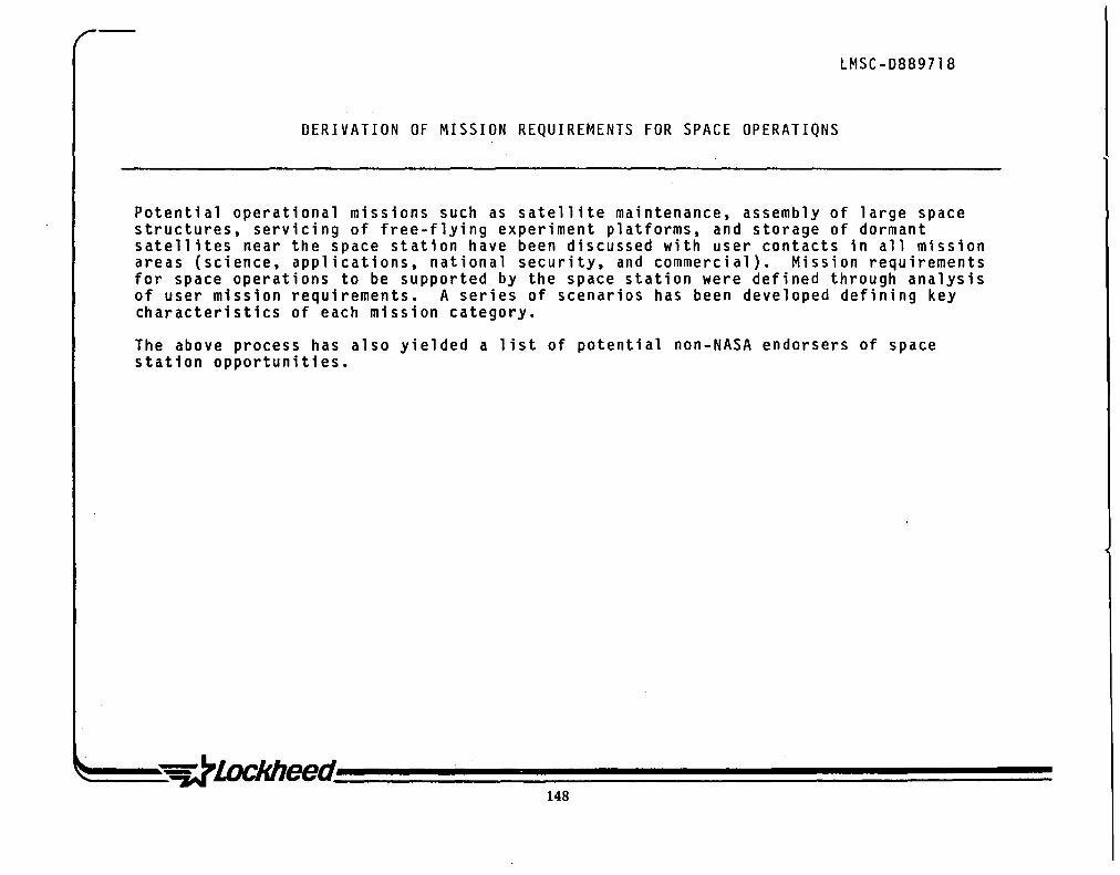
LMSC-D8897l8
DERIVATION OF MISSION REQUIREMENTS FOR SPACE OPERATIQNS
Potential operational missions such as satellite maintenance, assembly of large space structures, servicing of free-flying experiment platforms, and storage of dormant satellites near the space station have been discussed with user contacts in all mission areas (science, applications, national security, and commercial). Mission requirements for space operations to be supported by the space station were defined through analysis of user mission requirements. A series of scenarios has been developed defining key characteristics of each mission category.
The above process has also yielded a list of potential non-NASA endorsers of space station opportunities.
148

LMSC-D889718
DERIVATION OF MISSION REQUIREMENTS
_PROGRAMS ____ F_O_R_S_P_A_C_E_O_P_E_R_A_T_I_O_N_S __ ..... ___ --
•
•
•
•
POTENTIAL USER COMMUNITY FOR SPACE OPERATIONS DEVELOPED THROUGH USER CONTACTS IN ALL MISSION CATEGORIES.
OPERATION NEEDS FURTHER REFINED THROUGH REPEATED USER CONTACTS.
SPACE OPERATIONS REQUIREMENTS IDENTIFIED THROUGH ANALYSIS OF MISSION REQUIREMENTS AND ATTENDANT OPERATIONS NEEDS.
SCENARIOS DEVELOPED TO TEST AND IMPLEMENT DEFINITION OF OPERATIONS REQUIREMENTS.

LMSC-D8897l8
SPACE OPERATIONS
Operations from the space station are of two basic groups: onboard and remote. Onboard operations may include extravehicular activity (EVA) as well as internal vehicular activities (IVA) on the space station. Onboard operations also include docking maneuvers and stage assembly for orbit transfer vehicles (OTV) and payloads mounted on or tethered to the space station. Spacecraft servicing at the station is a fundamental operation that complements remote servicing. Early proof-of-technology demonstrations can be performed both internally and with attached hardware. Similar operations can be expected for research and development, which also includes construction and assembly in an attached mode.
Remote operations include servicing and support of all types of space operations in association with free-flying spacecraft. Remote operations would also include automated functions performed by an unmanned spacecraft servicing or docking with a remote satellite, even though the activities may be controlled and actively guided by a crewperson on-board the space station.
Requirements for onboard station operations are developed in response to various missions scenarios discussed in other sections. The space station will be designed to support onboard operations, and the station configuration will be developed to minimize inherent limitations. Some fundamental characteristics of the station (e.g., minimum gravity level or local contamination levels) will make onboard station operations unsuitable for certain payloads. Such specialized payloads will be placed on free-flying satellites and remotely supported. Orbit mechanics places several fundamental restrictions on remote operations and these limitations are the focus of the first subsection on space operations.
150

LMSC-D889718
SPACE OPERATIONS ... PROGRAMS __________________________________________________ ___
ION-BOARD STATION OPERATIONS II HEALTH AND WELFARE OF STATION ITSELF II SUPPORT OF ON-BOARD EXPERIMENTS. ASSEMBLY.
CONSTRUCTION. DOCKING AND TRANSFER. ETC. . i
I REMOTE OPERATIONS II SPACECRAFT SERVICING II SUPPORT FOR EXPERIMENTS. ASSEMBLY. CONSTRUCTION.
DOCKING. AND TRANSFER. PRODUCTION OPERATIONS. ETC .• ON FREE-FLYING SPACECRAFT
THE ENERGY REQUIRED TO SUPPORT SATELLITES IN LOW EARTH ORBIT (LEO) FROM THE SPACE STATION PLACES PRACTICAL CONSTRAINTS ON:
I ACCESSIBILITY I REVISIT FREQUENCY
I TYPE OF SERVICING OPERATIONS
151

LMSC-D8897l8
SCENARIOS FOR SPACE OPERATIONS ASSESSMENT
Seven representative systems were examined (see chart on facing page). Each system was studied for alternative ways to perform on-orbit operations and several individual cases were developed as a subset to each individual mission.
The missions were selected to represent various categories of space operations. In addition, they were chosen to represent the range of activities that would take place near the space station as well as remote from it.
152
(

SPACE LMSC-D889718
~ ___ PAOGRAMS ________________________________________________ __ SCENARIOS FOR SPACE OPERATIONS ASSESSMENT
• LARGE STRUCTURES ASSEMBLY (LARGE ANTENNA FOR SPACE RADAR)
• ASTRONOMY PLATFORM SUPPORT
• SPACE TELESCOPE MAINTENANCE
• ' SPACE BASED RADAR (ITSS) MAINTENANCE
• PROMPT SATELLITE REPLACEMENT
• SHUTTLE CREW RESCUE VEHICLE
• GEO SATELLITE RESUPPLY

•

c W0 00 0-a. Z
~.~ (1)0 I- W z::! -le:(-a:m I-a: (1)0 z> 8m

--------------------------------------------~~~--------------------------------------------------------------------------------

LMSC-D889718
SPACE
• fiiiiiiiii PR:RRMS iiiiiiiiiiiiiiiiiiiiiiiiiiiiiiiiiiiiiiiiiiiiiiiiiiiiiiiiiiiiiiiiiiiiiiiiiiiiiiiiiiiiiiiiiiiiiiiiiiiiiiiiiiiiiiiiiiiiiiiiiiiiiiiiiiiiiiiil
CATEGORY 1 HARD DOCKED PA VLOADS,
CAPTIVE FREE-FL VERS.
TETHERED SATELLITES

LMSC-D8897l8
CAPTIVE FREE-FLYER
While the impact of hard-docked payloads on the orbit mechanics of the space station presents no conceptual restraints, a hard-docked payload is subjected to the transient dynamic loads transferred through the station structure. This can have an adverse effect by disturbing the desired very low-g environment which some users (such as materials processing producers) assume they must have for extended periods of time. One way to obtain very low-g is to mount the experiment on a free-flying satellite which orbits the station (see category 2). This has the disadvantage that manned interaction with an experiment (or production process) on a frequent basis is difficult, or at the least inconvenient.
An alternative is to mount the payload on a support pallet contained inside a support structure envelope on the space station. While work is performed on the payload, it is hard-mounted to the station. During payload operation when low-g is desired, all supports are removed. An aerodynamic fairing can be used to create an even higher vacuum in its wake and to minimize the already very small drag forces. The effect of the surrounding space station structure on the vacuum level, as well as general contaminataion effects, will have to be examined for each specific configuration. Hardware based on such concepts have flown on many satellites, usually as a solid sphere inside a spherical container, and were used to provide signals for an inertial guidance and control system. The extension of this concept to a free-floating 20,OOO-lb payload with furnaces and radiators, as well as requirements for power and communication, may be nontrivial, but it is an appealing approach with potentially sUbstantial benefits.
This approach should work well, unless the space station is part of a tether system in which the station is not located at the center of mass.
158

SPACE LMSC-D889718
CAPTIVE FREE FLYER • ___ PROGRAMS __________________________________________________________ __
BASIC SPACE
STATION \
AEROOYNAMIC r.~:~ .. FAIRING ~- . ../v: .. ,',
'" ./ .l ' 0 " /'" .-...
(0 :~.. .' -
MOVABLE
,,·.U~{!0· ~ "'l:(' '1-....' • ~-,l(/II:o.
~(O //~ . • ~ 0 Jf:~ .~ ~O//
.j5 .. .gy CAPTIVE FREE FLYER IN OPERATIONAL POSITION
159
22 FT DIAM LABORATORY SUSPENDED IN THE LMSC REFERENCE SPACE STATION (ALTERNATE LOCATION FOR CAPTIVE FREE FLYER)
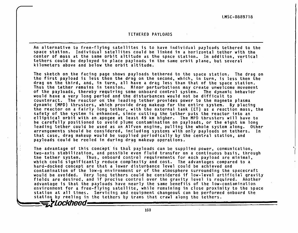
LMSC-D889718
TETHERED PAYLOADS
An alternative to free-flying satellites is to have individual payloads tethered to the space station. Individual satellites could be linked in a horizontal tether with the center of mass at the same orbit altitude as the space station. In addition, vertical tethers could be deployed to place payloads in the same orbit plane, but several kilometers above and below the orbit altitude.
The sketch on the facing page shows payloads tethered to the space station. The drag on the first payload is less then the drag on the second, which, in turn, is less then the drag on the third, and, in turn, all have a drag less than that of the space station. Thus the tether remains in tension. Minor perturbations may create unwelcome movement of the payloads, thereby requiring some onboard control system. The dynamic behavior would have a very long period and the disturbances would not be difficult to counteract. The reactor on the leading tether provides power to the magneto plasma dynamic (MPD) thrusters, which provide drag makeup for the entire system. By placing the reactor on a fairly long tether, with the external tank .(ET) as a reaction mass, the safety of the system is enhanced, since cutting the tether puts the reactor into an elliptical orbit with an'apogee at least 49 km h1gh~r. The MPD thrusters will have to be carefully positioned to avoid plume contamination on payloads, or the eight km long leading tether could be used as an A1fven engine, pulling the whole system along. Other arrangements should be considered, including systems with only payloads on tethers. In that case, drag makeup would be supplied periodically by the central station, and payloads could be reeled in duringdr~g makeup operations.
The advantage of this conc~ptis thai payloads can be supplied power, communication, two-a~is stabilization, and possible even fluid transfer on a continuous basis, thr6ugh the tether system. Thus, onboard control requirements for each payload are minimal, which could significantly reduce complexity and cost. The advantages compared to a hard-docked concept are that a lower disturbance level could be achieved and contamination of the 10w-g environment or of the atmosphere surrounding the spatecraft would be avoided. Very long tethers could be considered if low-level artificial gravity fields are desired, and if precise control over the gravity level is required. Another advantage is that the payloads have nearly the same benefits of the low-contamination environment for a free-flying satellite, while remaining in close proximity to the space station at all times. Servicing and equipment changeout can be performed onboard the station by reeling in the tethers by trams that crawl along the tethers.
~~~~hheed~~~~~~~~~~~~~~~~~ ffiO

SPACE
~ ~
U1SC-D889718
TETHERED PAYLOADS ___ PROGRAMS ________________________________________________________ ___
DRAG FORCES D1, D2, D3, D4
MUST HAVE RELATIONSHIP
Dl <D2 <D3 <D4
D 7 D1 2
D3 7 RADIATOR
EMERGENCY "JETTISON ~_ ROCKET ,.,
MPD
REAC"t'OR 1.0 MW
..,.....- Tt:JERMAL
ASTRONOMICS OBSERVATORY" THRUSTERS .... - 7.0 km
TETHER TRANSFERS POWER, PROVIDES COMMUNICATION LINKS, AND 2-AXIS STABILIZATION
LOW POWER 20 kW SOLAR ARRAY
BACKUP "
LARGE STRUCTURE ASSEMBLY AREA
MATERIALS \ PROCESSING
" 1-
MATERIALS PROCESSING
EARTH OBSERVATION
1-.._1.0 km
EXTERNAL TANK
BALLAST TO COUNTERWEIGHT REACTOR

LMSC-D8897l8
CATEGORY l--SUMMARY
Tethered payloads and captive free-flyers are attractive alternatives to free-flying satellites since central services (power. communication. two-axis stabilization. passive retrieval) can be provided by the space station and cost trades should prove favorable. The concept of a captive free-flyer is that the payload pallet and equipment drift entirely free. but are contained entirely within the space station structure during operation. Activities such as docking and orbit decay due to drag will cause relative motion between the space station and the captive free-flyer which will limit the duration of free flight (frequent or continuous drag makeup by the station can help). Also the need to transmit power and provide a data link may dictate that cables be used which will also perturb the isolated free flight. For tethered satellites. the tether loads are very low and electric power losses are minimal even for very small conductor sizes; thus the weight of the tether is small if the tether length is less than 10 km. For some applications. tether lengths greater than 100 km are feasible. The tether provides a continuous load on the payload. however. and the gravity levels (a function of tether length) must be reconciled with mission requirements.
162
(

LMSC-D889718
CATEGORY 1 - SUMMARY ... PROGRAMS __________________________________________________ ___
HARD DOCKED PAYLOADS. CAPTIVE FREE-FLYERS. AND TETHERED SATELLITES
ENERGY REQUIRED:
REVISIT FREQUENCY:
OPERATIONS:
ORBIT TRANSFER VEH:
PAYLOAD LOCATION:
FORCES REQUIRED TO REEL IN THE TETHERS ARE SMALL BUT SYSTEM TRADES ARE REQUIRED TO COMPARE WITH TMS ENERGY REQUIREMENTS FOR SERVICING FREE-FLYERS.
UNLIMITED (CONSTRAINED ONLY BE REQUIREMENTS FOR OTHER ON-BOARD PROGRAMS)
UNLIMITED (EXCEPT FOR LOW - BUT FINITE - GRAVITY FIELD DEVELOPED IN TETHER SYSTEMS) EXAMPLES: •
• • EARTH RESOURCES ASTRONOMICAL OBSERVATORY MATERIAL PROCESSING
NONE REQUIRED. PAYLOADS HARD DOCKED OR CAPTIVE ARE PHYSICALLY ATTACHED TO PLATFORM - AT MOST EVA MAY BE REQUIRED. PAYLOADS ON TETHERS ARE REELED IN TO STATION. OR TRAM CAN TRAVEL ON TETHER TO DEPLOYED PAYLOADS
ATTACHED VIA TETHER (METERS TO KILOMETERS LONG) TO STATION


LMSC-D889718
fjiiiiiiiii PROGRAMS .... iiiiiiiiiiiiiiiiiiiiiiiiiiiiiiiiiiiiiiiiiiiiiiiiiiiiiiiiiiiiiiiiiiiiiiiiiiiiiiiiiiiiiiiiiiiiiiiiiiiiiiiiiiiiiiiiiiiiiiiiiiiiiiiiiiiiiil
CATEGORY 2 -SUPPORT OF SATELLITES
IN LOCAL STATION· VICINITY
• ·CLUSTER FREE-FLYER-• EXPERIMENTS, PRODUCTION OPERATIONS,
ASSEMBLY/CONSTRUCTION

LMSC-D8897l8
FREE-FLYER IN CIRCULAR EARTH ORBIT
Two approaches will be considered for keeping satellites in the vicinity of the space station: use of the drag characteristics of the free-flyer satellite, and use of an elliptic orbit.
The first concept (shown on the facing page) is to use the drag characteristics of the free-flying satellite (also called a cluster free-flyer) to control its position relative to the space station. At day zero, the satellite is approximately 4 nmi above the altitude of, and 35 deg in advance of the station. The 35 deg limit was selected to provide line-of-sight capability for communication between the space station and the satellite, thereby minimizing the complexity of the communication system for the free-flyer. The 35 deg limit combined with the satellite drag fixes the maximum altitude of the free-flyer. Both the station and the satellite orbit in the same direction and are coplanar. Because the satellite is initally slightly higher in altitude, its period is slightly longer and, to an observer on the station, it appears that the satellite is moving backward. Because of aerodynamic drag, the free-flying satellite gradually decreases its altitude and, after about 15 days its orbit will have decayed to that of the space station. The satellite is now 35 deg behind the space station. The orbit of the free-flyer will continue to decay and, since its altitude is now less than that of the space station, its period will be shorter. To an observer on the space station, the -free-flyer appears to catch up and pass below the station. At the end of thirty days the free-flyer will be at a point 35 deg in advance of the space station. At this point, the free-flyer will be reboosted by onboard propulsion to a position identical to its starting point and the process will be repeated. Corrections will be made to the nodal drift to insure that the cluster free-flyer, on the average, remains coplanar with the space station. The cycle time for this process is 30 days for a high-drag free-flyer, and may increase to 90 or more days for a configuration with a lower ballistic coefficient. Solar flare ativity will also affect cycle time. The advantage of this process is that reboost is not required until after the 30 or more days, and thus one obtains a maximum duration, zero- g environment.
At its most extreme point the free-flyer will be about 2,500 miles from the space station. The one-day transfer can be performed using the TMS, or the satellite on-board propulsion could be used to return to the station halfway through the reboost at negligible delta V penalty.
~~~~eed~~~~~~~~~~~~~~~~ 166

SPACE
• OPTION 1-FREE-FL YER IN CIRCULAR EARTH ORBIT
LMSC-D8897 I 8
___ PROGRAMS __________________________________________________________ __
L CLUSTER FREE-FLYER
MINIMUM SERVICE ~ RELATIVE TRAJECTORY IMPULSE ROUND TRIP
IlV=9FPS~( - - _____ -.....~~
"", ~ r MAXIMUM SERVICE , ......... DAY ZERO 377 km /' ; IMPULSE - ONE DAY "
J/ --.. RENDEZVOUS, ROUND TRIP --.I , EJ A V = 160 FPS // ----------II~· "
","" SPACE J ~, I - STATION SMALL ,. ·370 km ~ .
VEH ICLE . .c... 1:;7 (e.g., TMS) ~
00 CLUSTER / , $l(q,'?\ .FREE FLYER-./' ,,~~
363 km ,,/
----~-- DAY 30 ~
NOTE: EXAMPLE SHOWN FOR HIGH-DRAG CLUSTER FREE-FLYER

LMSC-D8897l8
FREE-FLYER IN ELLIPTICAL EARTH ORBIT
The second means to achieve a system in which free-flying satellites orbit the space station is to place the free-flyer in an elliptical orbit of identical period to that of the space station. The apogee could be 230 nmi and the perigee 210 nmi if the station is at 220-nmi circular. To an observer on the space station, the free-flyer appears to orbit the space station. As in the preceding case, the space station is assumed to continuously maintain its orbit by use of drag makeup via onboard propulsion (e.g., conventional thrusters, ion thrusters, electromotive forces on tether).
In this mode, the free-flyer .wi11 maintain its position relative to the space station through frequent thruster firings to provide drag makeup. This may be a disadvantage of this approach compared to option 1, since the interval of undisturbed flight is probably shorter. If the drag makeup thruster firings are not detrimental to payload functions this option is advantageous since the free-flyer remains closer to the station (compared to option 1).

LMSC-D889718 SPACE
a OPTION 2- FREE FLYER IN ELLIPTICAL EARTH ORBIT ___ PROGRAMS ________________________________________________________ _
FREE
SPACE STATION
ORBIT (CIRCULAR)
FLYER _---....,. ORBIT
(ELLIPTICAL)
~J. SPACE ~~_=-_ ~~S~ATION
EJ ~J "
" '\
STATION ORBIT
220 nmi CIRCULAR 28.5 DEG
FREE FLYER ORBIT
230 NMI APOGEE 210 NMI PERIGEE 28.5 DEG
\
~, EARTH
169
FREE FLYER , \
~] I

LMSC-D8897l8
CATEGORY 2 -- SUMMARY
Apart from payloads attached to the station, satellites that remain in the local of the space station are an important group of vehicles to be supported. There are many ways for a free-flying satellite to remain in the station vicinity; two primary concepts have been discussed in this section. There are no extreme constraints on the revisit frequency, nor are there constraints on the type of operations that may be performed in this environment. The dwell time at the satellite being serviced is limited only by the constraints of the life support system for manned operations or by the characteri~tics of an unmanned transfer vehicle. Other satellites in other orbits have severe constraints on the dwell time available for all support operations.
The energy required to reach the free-flying satellite from the space station is low -and it is entirely feasible to consider moving the free-flying satellite to the space station for more complex operations. The free-flyer can be returned to its operational orbit at any time without significant penalty. Again, this is not true for other types of servicing operations discussed later~
The only restrictions imposed on these free-flyers is that satellites in this group must be coplanar with the space station and must be within a few nautical miles of the station altitude. This imposes constraints on the type of satellites that can be considered since operational requirements dictate selection of other orbit characteristics for many missions. It is even possible for the sttaion itself to temporarily desert the cluster (e.g., due to tethered momentum transfer operations), as long as the station can compensate or nodal drift, etc. (this is most simply done by planning a sequence of operations that keep the average and final station altitudes equal to the initial station and cluster altitude).
170

LMSC-D889718 SPACE
• ___ PROGRAMS ____________________________________________________ _ CATEGORY 2 - SUMMARY
SUPPORT OF SATELLITES IN LOCAL STATION VICINITY
ENERGY REQUIRED:
REVISIT FREQUENCY:
OPERATIONS:
ORBIT TRANSFER VEH:
SATELLITE LOCATION:
AV <: 160 FPS
UNLIMITED
UNLIMITED -- EXCEPT FOR CAPABILITY LIMITS OF TMS OR OTV
EXAMPLES: --
TMS TYPE
• ON-ORBIT CONSTRUCTION OF SPACECRAFT
• ASTRONOMY PLATFORM
SAME INCLINATION AS STATION ALTITUDE WITHIN A FEW NM FROM STATION ALTITUDE 30 TO 90 DAY INTERVAL BETWEEN REBOOST MANEUVERS
171

U1SC-D889718
riiiiiiiiiiii PR OGRAMS iiiiiiiiiiiiiiiiiiiiiiiiiiiiiiiiiiiiiiiiiiiiiiiiiiiiiiiiiiiiiiiiiiiiiiiiiiiiiiiiiiiiiiiiiiiiiiiiiiiiiiiiiiiiiiiiiiiiiiiiiiiiiiiiiiiiiiiiiiiiiiiiiiiiiiiiiiiiiiiiiiiiiiiiiiiiiiiiiiiiil
CATEGORY 3 -SUPPORT OF SATELLITES IN NEARBY INCLINATION AT NODAL COINCIDENCE
EXAMPLES: • SPACE TELESCOPE . SCHEDULE D MAINTENANCE
• ITSS SPACE-BASED RADAR ". SCHEDULED MAINTENANCE

LMSC-D8897l8
SPACE-BASED SATELLITE SERVICING ENVELOPE
The operational capability of an OTV is a function of its total impulse (controlled by the propellant and engine configuration), the vehicle's inert weight, presence or absence of an aerobraking system, payload to be carried, and whether the payload is to be transferred in a placement mission, a retrieval mission, or a combination of both. Given these characteristics, one can compute the volume of space that can be reached by the specific OTV. All satellites within that volume could be supported by the space station with a space-station-based OTV. This assumes, of course, that the satellite is designed to be serviced or otherwise supported by the space station.
Specific satellites passing through the service volume,of the OTV will change as a function of time. Understanding this change is essential to define the capabilities and usefulness of space-based satellite servicing. In this section, we will consider OTVs comparable to the Centaur wide body, modified as a reusable system. For energy levels required for orbit transfer at nodal coincidence, aerobraking systems are beneficial, but not required. A reusable 'OTV is highly desirable for economic reasons.
174

SPACE LMSC-D889718
SPACE.-BASED SATELLITE SERVICING ENVELOPE AT A GIVEN INSTANT OF TIME • ___ PROGRAMS ________________________________________________________ __
AT A GIVEN INSTANT IN TIME SATELLITES IN THIS VOLUME CAN BE SERVICED BY SPACE-STATION BASED ORBIT TRANSFI;~ VEHICLE
175
SPACE STATION ORBIT
EQUATORIAL ,PLANE
L MAX IMUM SATELLITE ALTITUDE IN STATION ORBIT PLANE
TYPICAL SATELLITE ORBIT ALTITUDE AND INCLINATION

LMSC-D8897l8
ORBITAL TRANSFERS WITH AEROBRAKING
Aerobraking is an emerging technology that offers great potential for expanding the capability of OTVsby increasing the usable range without increasing propellant requirements. Preliminary studies have been performed by several contractors and NASA centers and, based on available data, it is reasonable to assume that an aerobraking system would add approximately 3,000 lb. to the inert weight of the OTV. This weight increase is offset by a substantial gain in delta velocity during orbit transfer. The actual benefit from the aerobraking maneuver depends on details of the specific orbit transfer. Studies indicte that the maximum gain from aerobraking is limited to 7,000 ft/sec. and this limit has been used in the analysis which produced the results displayed in the following pages.
Aerobraking can be used on both ascent and return transfers as shown on the facing page. For low-energy transfers, the Hohmann two-burn trajectory provides the minimum energy transfer. In this regime, aerobraking is useful only on descent (OTV return, case A); a modified two-burn trajectory is used, with most or all the intermediate burn energy coming from aerobraking. As energy levels increase, the three-burn trajectory becomes more economical (generally when the plane change exceeds 25 deg.or so) and a more complex orbit transfer path is followed. Aerobraking in this regime to reduce the energy required for both ascent and return (see payload placement and OTV return, case B). The apogee is increased as energy requirements for the transfer are increased (e.g., making large plane change). Ultimately, the unconstrained transfer involves a second burn at infinity and the transfer time becomes infinite. In the analysis cont~i-ned---here, the apogee was limited to 50,000 miles to constrain the orbit transfer time to 35 hr. maximum. Allowing the apogee increase would have only a modest effect on the results contained herein and would not alter any trends or conclusions reached.

SPACE LMSC-D889718
ORBITAL TRANSFERS WITH AEROBRAKING • ... PROGRAMS __________________________________________________________ __
AV 2 .... " . /' '"
I ,
/ '\
t AV 3 INITIAL \, ~,.. ... -:-ORBIT
I \
PAYLOAD PLACEMENT
I , ,
INITIAL ORBIT
CASE A CASE B
OTV RETURN
177

TYPICAL PROPELLANT WEIGHT VERSUS DELTA VELOCITY FOR A 10,000-LB PAYLOAD
LMSC-D889718
The propellant required to achieve a given change in velocity is a function of the OTV characteristics and payload to be carried. On the facing page, data are shown for an OTV with an inert weight of 3000 1b for the basic structure and equipment plus a propulsion system weight equal to 0.11 times the propellant weight. This is equivalent to a mass fraction of 0.87 for high propellant weights and to 0.70 for small propellant loads. This is consistent with a design for a cryogenic transfer vehicle with no provision for aerobraking. Another set of curves is shown for an OTV with the structure and equipment weight increased to 6000 lb. The added inert weight is to account for an aerobraking system. These figures represent typical capabilities and a specific design will yield somewhat different results. The specific impulse of 440 is consistent with current capabilities for a cryogenic propulsion system.
Four cases are examined: ascent and return with a 10-k1b payload, ascent empty and return with a 10-k1b payload, ascent with a 10-k1b payload and return empty, and a one-way transit (ascent only) with a 10-k1b payload.
In combining the curves for cases 1 and 2, it is assumed that the delta V for a one-way ascent is half that for roundtrip cases. For example, if a one-way transfer, case 1, requires 10,000 ft/sec , then cases 2, 3, and 4 require 20,000 ft/sec. The quantity of propellants for cases 1 to 4 are then 19, 75, 60, and 45 thousand pounds, respectively, for an OTV with aerobraking.
The 10-k1b payload was selected because it is representative of small payloads of interest to science, applications, and commercial research users. It is also typical of a minimum weight for a manned capsule.

SPACE
PROPELLANT WEIGHTS VS llV FOR 10K LB PAYLOAD
LMSC-D889718
ai· ___ PROGRAMS ________________________________________________________ _
140 ~----II-----.r-----.-------r_--_yIr~~rI
0 .. w.1III!::::"'~_ ~ .. --~_~---:'-. --~~.----.lI,......-~_ , 0 5 10 15 20 25 30 .
CASE
1 - ONE WAY (ASCENT) WITH PAYLOAD
2 - ASCEND WITH PAYLOAD" RETURN WITH PAYLOAD
3 - ASCEND EMPTY, RETURN WITH PAYLOAD
4 - ASCEND WITH PAYLOAD, RETURN EMPTY
OTV INERT WEIGHT CONFIG A
STRUCTURE, EQUIPMENT WITHOUT AEROBRAKE 3,000 LB PLUS ~ PROPULSION SYSTEM MASS FRACTION = 0.90
CONFIG B STRUCTURE, EQUIPMENT WITH AEROBRAKE 6,000 LB PLUS .. ' PROPULSION SYSTEM MASS FRACTION = 0.90
EXAMPLE: CONFIG B WITH 45 K LB PROP.
STRUCTURE, ETC. 6,000 LB PROPULSioN SYS 5,000 LB
TOTAL 11,000 LB DELTA V (FT/SEC *1000-) L-______________ -J

MINIMUM DELTA VELOCITY REQUIRED FOR ROUND TRIP BETWEEN SPACE STATIDN AND SATELLITE
LMSC-D8897l8
Contours of constant delta V are shown on the facing page for .roundtrip orbit transfers involving a combination of altitude and inclination change. These computations assume that the space station is at 220-nmi circular orbit. These data are valid for any space station inclination.
For cases in this regime, aerobraking is effective only on return missions, because orbit transfer involves comparatively small plane changes. The added complexity and weight of the aerobraking systems must be traded against propellant saved. For servicing missions up to lS-deg plane change at low altitude (less than a few thousand nautical miles), aerobraking systems are not required and they do not appear to offer dramatic enhancement. Cases in which aerobraking has a dramatic impact will be discussed later.
These curves assume there is no delay at the satellite operational altitude. Since the transit time is on the order of hours each way, the effect of nodal drift is negligible. If there is an extended delay to perform operations on the satellite at operational altitude, the energy required for the roundtrip transfer can be substantially affected, as discussed in the following pages.

SPACE LMSC-D889718
•
TATION MINIMUM DELTA V REQUIRED FOR ROUND TRIP --------o ..... BETWEEN SPACE STATION AND SATELLITE
... PROGRAMS ________________________________________________________ ___
:E z 0 0 0 -w c ::> I--I-.J 0(
I-m 0: 0 w U
> 0: w C/)
I WITHOUT WITH ... 1 10 .... 4t--- AEROBRAKING __ I. AEROBRAKING ----I-~
20
8
~
"
2
20
o ----~~--~----~----~----~----~ -30 -20 -10 0 10 20 30
SERVICE ORBIT INCLINATION (DEG)
SPACE STATION:
220 NMI CIRCULAR
NO DELAY AT SERV. ORBIT
DEVIATION FROM SPACE STATION INCLINATION
~~~~~~~~~~~~~~~~~~~hheed~~ 181

LMSC-D8897l8
EFFECT OF NODAL DRIFT OF CIRCULAR ORBITS
From our discussions, we found that many users did not recognize the effect of nodal drift and its impact on energy required for orbit transfers. The minimum energy transfer between satellites in two different orbits occurs when both orbits cross the equator at the same pOint (nodal coincidence). The relationship between two orbits changes as a function of time, and the interval between nodal coincidences can be sUbstantial.
Two satellites with orbits at the same inclination but different altitudes also experience relative nodal drift. The plane change required to transfer from one orbit to another at a different altitude but with the same inclination will vary from zero at nodal coincidence to a maximum equal to twice the inclination when the satellites are l80-deg. out of phase. The minimum plane change to transfer from a satellite in one orbit to a satellite in another at a different inclination occurs at nodal coincidence and is equal to the difference in inclinations. '
182

SPACE
LMSC-D889718
EFFECT OF NODAL DRIFT OF CIRCULAR ORBITS AT SAME INCLINATION
BUT WITH DIFFERENT ALTITUDES ii ___ PROGRAMS ______________________________________________________ _
TIME t = 0
ORBIT 1 AND ORBIT 2 ARE COPLANAR BOTH HAVE SAME INCLINATION 01 = i2l
TIME t =T
ORBIT 1 AND ORBIT 2 ARE NOT COPLANAR BOTH HAVE SAME INCLINATION 01 = i 2)

LMSC-D8897l8
INTERVAL BETWEEN NODAL COINCIDENCES OF A 28.S-DEG. SPACE STATION AND SATELLITE
The time interval between successive nodal coincidences of orbits for a space station and a satellite is a function of inclination and altitude of the space station and satellite. For a space station located at 220-nmi circular and 28.S-deg. inclination, contours of constant time between nodal coincidences are shown on the facing page. Since the nodal regression of satellites at high altitudes is very small, the minimum interval between nodal coincidences occurs with satellites in high Earth orbit. Satellites which have orbits very close in altitude to the space station have the longest interval between nodal coincidences. For this case, the minimum interval is about SO days. For satellites in a 600-nmi orbit at' 28.S-deg., the interval more than doubles. For satellites in nearly the same altitude as the station, the interval between nodal coincidences can be years. For instance, the interval for a 300-nmi, 28.S-deg. satellite is 23 months.
184
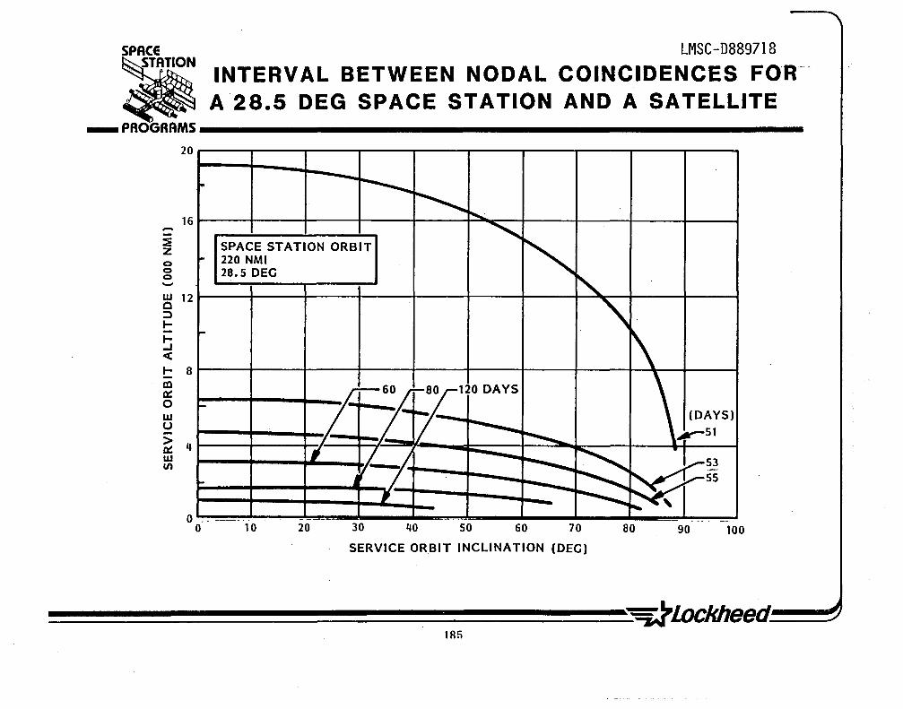
SPACE LMSC-D889718
INTERVAL BETWEEN NODAL COINCIDENCES FOR A28.5 DEG SPACE STATION AND A SATELLITE • ___ PROGRAMS ______________________________________________________ __
-:E z o o o -
20
16
w 12 a :::> l-I--I c(
I- 8 In ~ o w U
~ 4 w V)
o
.
~
P-
-
---o
-~ ~ ~
"' SPACE STATION ORBIT
" 220 NMI 28.5 DEC
~ ~
\ t
-60/ rT-12:: .f- \. (DAYS)
r--........... ,...-51 7
; it ~ •
~
~ ....-5~
--... :::::::: ....-55 , -- - ~ . -. - - --- .. --- -.-..
10 20 30 40 50 60 70 80 90 100
SERVICE ORBIT INCLINATION (DEC)
lRfi

LMSC-D8897l8
DELTA V FOR NON-OPTIMUM ORBIT TRANSFER
The chart on the facing page shows the delta V required to make an orbit transfer anytime between a space station at 220-nmi circular orbit at 60-deg, and a satellite at l,400-nmi in a circular orbit at 60-deg. The delta V required to transfer is computed using an optimized two-or three-burn maneuver with or without aerobraking. The roundtrip energy is substantially reduced if aerobraking is used on both ascent and return maneuver. The maximum apogee is limited to 50,000 miles for the three-burn maneuvers. Higher altitudes require slightly less energy, but with increased transit time. One-way transit time varies from approximately one hour for the region around nodal coincidence to a maximum of 35 hours in regions where the roundtrip delta V exceeds 25,000 ft/sec. The transit time is essentially the same with or without aerobraking. The effect of aerobraking depends on the specific transfer; however the upper limit is a maximum 7,000 ft/sec. benefit on both ascent and return.
A minimum energy roundtrip can be realized by making an immediate ascent (required, for instance, to place a spare satellite in operation), with the return flight made at nodal coincidence. The disadvantage is that the OTV and payload (if any) to be returned must wait several months on orbit before returning to the space station. An alternative mode is to immediately return to an operational altitude serviced by the Space Shuttle; the delta V required for that transfer is the same as a transfer to the station at nodal coincidence.

SPACE U'1SC-D889718
DELTA V FOR TRANSFER AT NON-OPTIMUM TIME • ___ PROGRAMS __________________________________________ ~--------------...
-U) DU.
NODAL COINCIDENCE
SPACE STATION: 220 NMI CIRCULAR 60 DEGREES
SATELLITE: 1,400 NMI CIRCULAR 60 DEGREES
60 r-----~r-------.-------~--~~_r------_.--------r_------,_--~ ROUND T IP ORBIT NSFER IMMEDIATE ASCENT AND RETURN
g 50 • ALL· PROPULSIVE (2 OR 3 BURN LIMIT OF
----+-------~-------+--------~SINGLE-STAGE o. -c w
• WITH AEROBRAKING TRANSFER
~ 40 r---~~r-------++----~~------_+--~--~--------~~~--~--~ ::> C1 w ~
> < ~
·w c 20 r-~----r_------+_------~~--~~------~~~~~~----~M_--~ ,r ..... -- ............... [ ROUND TRIP ORBIT TRANSFER
10 I-f------r--------t-------~--_\__#__+~; IMMEDIATE ASCENT (WITH t--lr--t
AEROBRAKINGl
o ----~--~--~--~--~--~--~--~--~------~----~--~--~--~ o 40 so 120 160 200' 240, 2S0
DAYS WAIT BEFORE ASCENT
187
= 0.94 = 440 = 0.S7

LMSC-D889718
CATEGORY 3-SUMMARY SUPPORT OF SATELLITES IN NEARBY INCLINATION AT NODAL COINCIDENCE
The space station can be a cost-effective base for support to satellites at nodal coincidence in nearby inclinations. Even if we constrain orbit transfer to a delta V less than 15,000 ft/sec. for a round-trip transfer, the space station can ~rovide a base to service satellites over 4,000 miles above it and up to 15 deg. inclination change. The constraint on the delta V keeps the transfer within the range where aerobraking is not beneficial. This simplifies the OTV configuration and allows us to use the Centaur and the proposed TMS.
Significant constraints are imposed by the limited time available for orbit operations at nodal coincidence and the relatively long period between nodal coincidences. Never the less, scheduled maintenance can be planned years in advance and represents a significant of potential business for the space station. In subsequent charts discussing space operation mission scenarios, it is shown that there is a substantial cost benefit to use of the space station rather than the Space Shuttle for servicing •
188

LMSC-D889718 SPACE ------- -
_
ATION CATEGORY 3 - SUMMARY SUPPORT OF SATElliTES IN NEARBY INCLINATION
AT NODAL COINCIDENCE ... PROGRAMS ________________________________________________ __
ENERGY REQUIRED:
REVISIT FREQUENCY:
OPERATIONS:
OTV:
SATELLITE LOCATION:
6V < 15,000 FPS ROUND TRIP
60 TO 300 PLUS DAYS DEPENDING ON SATELLITE AND STATION INCLINATIONS AND ALTITUDES
SCHEDULED MAINTENANCE: • EQUIPMENT CHANGEOUT • PRODUCT OR EXPERIMENT SERVICING • SPARES AND/OR FLUID RESUPPLY
• G&C UPDATE \JINDOW FOR SERVICING LIMITED TO FEW DI\YS (IF SATELLITE IS TO REMAIN IN, OR BE RETURNED TO, ORIGINAL OPERATIONAL ORBIT)
CENTAUR TYPE - AEROBRAKING NOT REQUIRED, BUT IT SIGNIFICANTLY INCREASES ROUND TRIP CAPABILITY
INCLINATION ± 15 DEGREES FROM STATION INCLINATION AL TITUDE < 4000 NM
189


CATEGORY 4 -UNIVERSAL SUPPORT OF LOW EARTH ORBIT (LEO) SATELLITES
• ONE-WAY ORBIT TRANSFER • TYPICAL MISSIONS
-ON ORBIT LAUNCH OF SPARE SATEWTE
(e.g. ITSS SPACE-BASED RADAR)
-SPACE SHUTTLE ORBITER CREW
RESCUE VEHICLE
LMSC-D889718

LMSC-D8897l8
DELTA VELOCITY REQUIRED FOR ORBIT TRANSFER AT N~N-OPTIMUM TIMES (WITHOUT AEROBRAKING)
In this section, we will examine more carefully the impact of orbit transfer at non-optimal times. A particular focus will be the influence of space station location on the energy required for orbit transfer.
Four sets of curves are presented in the figure on the facing page. The data for the delta V required to transfer from a station at 60-deg, 220-nmi, to a satellite at 60 deg, l400-nmi are identical to the data shown earlier. The energy required to transfer to a 600-nmi. satellite is also shown; interestingly, although the energy at nodal coincidence i~ significantly lower, the maximum energy for orbit transfer at non-optimum time is essentially the same, independent of s~acecraft altitude. Also, if the space station were at 28.5-deg the energy required for orbit transfer to the 60-deg satellite location at nodal coincidence is substantially increased but the energy required for transfer at a .non-optimum time is not significantly different, and, in fact, is lower than the peak energy required from the 60 deg station.
Note,.that these non-optimal tr~nsfers use a three burn trajectory with the intermediate apogee set not to exceed 50,000-nmi No aerobraking was used in determining these roundtrip delta V requirements.
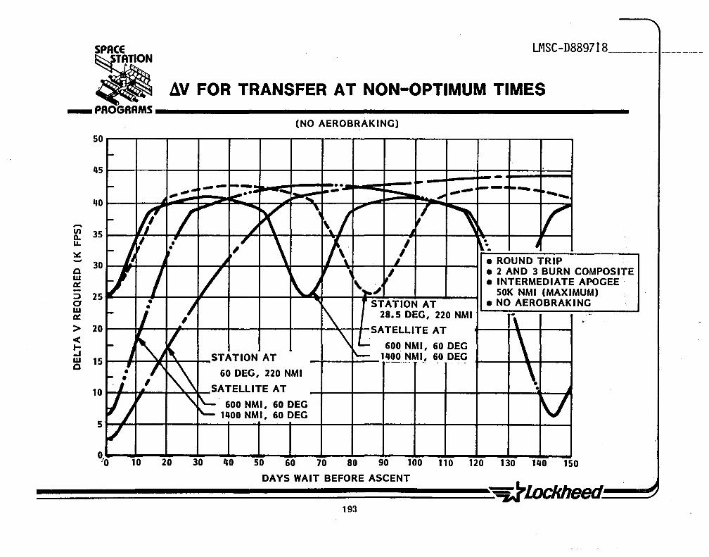
SPACE L~1SC-D889718 _______________ _
~ ~ 4V FOR TRANSFER AT NON-OPTIMUM TIMES ___ PAOGRAMS ____________________________________________________________ __
(NO AEROBRAKINC)
50
-45 -40
-en 35 D. I.L
~ - 30 a w Q: -:::J 25 a w a: > 20 c( t--I w 15 Q
10
5
~ --~- .. •• ~ ~-. ~- .. .". .". -- _ ... -..... -.- ..,. ....
~----~ ,
If / ". ~ p( '~ \/
~ ,i i\ I{ ~
~ j
~ t " .' , \ !\ I r·. J • ,
t I' ,J • ROUND TRIP
'r/ / / , , -, l • 2 AND 3 BURN COMPOSITE
\i ',..,;, • INTERMEDIATE APOGEE· 50K NMI (MAXIMUM)
- ,I " STATION AT • NO AEROBRAKINC ~ ,- li 28.5 DEC, 220 NMI \
.. . .. SATELLITE AT
~
J ~J ( \ L 600 NMI, 60 DEC \ STATION AT "- 1~OOo~MI_, 6.0 DE~ .' I' ,,\ 60 DEC, 220 NMI \ '"" . 01 ,
SA TELLITE AT ~ • ~
Ij " '\ ~ 600 NMI, 60 DEC V 1"00 NMI, 60 DEC
./ 10 20 30 "0 50 60 70 80 90 100 110 120 130 1"0 150
DAYS WAIT BEFORE ASCENT
~~~~~~~~~~~~~~~~~~~d~~ 193

CATEGORY 4-SUMMARY UNIVERAL SUPPORT OF LEO SATELLITES
LMSC-D8897l8
The eight cases examined on the preceding pages are significant because they highlight the fact that, for minimum energy transfer at non-optimum times, the location at the space station has only a small influence on total transfer energy. Also, aerobraking has a profound affect in reducing the energy required for these non-optimum transfers.
There are several of important missions that require such immediate response. An example is the rescue of a Shuttle orbiter crew. Another is. replacing an operational satellite that has failed and when there is a time-critical need to replace the failed satellite. These scenarios are explored further in subsequent sections.

LMSC-D88.97 t8 SPACE
CATEGORY 4 - SUMMARY UNIVERSAL SUPPORT OF LOW EARTH ORBIT
(LEO) SATELLITES • ... PROGRAMS ________________________________________________ __
ENERGY REQUIRED:
REVISIT FREQUENCY:
OPERATIONS:
OTV:
SATELLITE LOCATION:
~V < 23,000 FPS - NO AEROBRAKING ~ V < 17,000 F P S - WITH AEROBRAKING
(FOR ONE-WAY TRANSFER)·
UNLIMITED (TRANSFER TIME VARIES FROM 1 HOUR TO 35 HOURS, DEPENDING ON SATELLITE AND STATION LOCATIONS)
PRIMARILY USEFUL WHEN SHORT RESPONSE TIME IS REQUIRED: SHUTTLE-BASED SERVICING WILL BE COMPETITIVE IN OTHER CASES
WIDE-BODE CENTAUR TYPE - WITH AD~ITION OF AEROBRAKING
UNLIMITED .PROPELLANT STORED AT KEY ORBITS(E.G. 28.5°, 60°, 98°) COULD ALLOW AUTOMATED REFUELING OF OTV FOR RETURN FLIGHT


CATEGORY 5, -UNIVERSAL SUPPORT OF GEOSYNCHRONOUS EARTH ORBIT (GEO ) SATELLITES
• PLACEMENT OF LARGE SATELLITES
• REFUELING • AUTOMATED CHANGEOUT • MANNED MISSIONS
LMSC-D889718

LMSC-D889718
DELTA V FOR IMPULSIVE TRANSFER TO O-DEG. GEO SATELLITE
One potential servicing mission for a space-station-based OTV is one-way support of GEO satellites. First, we will consider GEO satellites at O-deg. inclination. Since there is no nodal drift between the station and a ,O-deg. inclination satellite, a two-dimensional plot of required delta V versus station inclination is adequate to define the effect of station inclination on transfer energy. Time (days wait before ascent) is not a factor in this instance. As shown on the facing page, the minimum energy transfer is made with a three-burn trajectory but without aerobraking. Since the terminal altitude is so high (19,323-nmi) an aerobraking trajectory (with a constrained maximum apogee of 50,OOO-nmi) on the ascent maneuver is of no benefit. Aerobraking will reduce the energy required on the return trajectory.
As shown in the graph, there is an effect of station location on the delta V required the transfer to GEO. However, the basic energy requirement is close to 15,000 ft/sec., which is similar to the energy required to reach an LEO satellite at non-optimum times. Transfers at this level are clearly within the capability of existing spacecraft such as the Centaur or the IUS. The propellant required to make the transfer or, conversely, the payload limitations of existing OTVs, can be determined from the data on pages OP-15 and OP-16.
198

SPACE LMSC-D889718
• DELTA V FOR TRANSFER TO o DEG GEOSYNCHRONOUS EARTH ORBIT SATELLITE ___ PROGRAMS __________________________________________________________ __
25 r-----r-~--~----~----._----~----~----~----~----~----~ stATION AT I
220 NMI, VARIOUS INCL
SATELLITE AT 19,323 NMI, 0 DEG
20 r-----r-----+-----+-----+-----;-----;-----4-----~----~----~
Vi' ONE-WAY TRANSFER ft i- WITHOUT AEROBRAK ING __ -
l~~=l===A~.S~CtE~N~T~r~-tll::;~;;~~~~~~~~~:::'-j=--~--~--~=:::~ .- t ONE-WAY TRANSFER a~::J 15 RETURNT .: .,..~-.~--:.~--=~ WITH AEROBRAKING __
w (50,000 NMI MAX. APOGEE) ....... ""' ....... 0:: . "ASCENT: ..... -~~ > r RETURN '-" ~ -----< 10 r-----r-----+-----+-----+---+-+-~~~~--4-----4-----~----~ . ~ .J,. .... "."'" -w ..... 1--" o I- , .............. -- .......
~--~--5 ~----r-----+-----+-----+-----4-----4-----4-----~----~----~
o o 10 20 30 40 50 60 70 80 90 100
STATION INCLINATION (DEG)

CATEGORY 5-SUMMARY UNIVERSAL SUPPORT OF GEO SATELLITE
LMSC-D8897l8
The energy required to reach GEO is comparable to that required to reach LEO orbits at non-optimum time. One significant difference is that aerobraking is not of value on GEO ascent missions, while aerobraking has a substantial effect in reducing energy required for LEO transfers. The energy required to reach GEO is not radically affected by space station orbit inclination, although there is a significant difference in delta V required for a GEO transfer from a 90-deg. station compared to a zero-degree station~
Orbit transfer to GEO is obviously within the capability of existing OTVs. Using a pair of OTVs in tandem can increase the payload capability significantly. thus allowing ~se of existing OTVs for space-based" operations. Clearly. space operations can be performed from a space station without building a new OTV.
200

SPACE LMSC-D889718
CATEGORY 5 - SUMMARY UNIVERSAL SUPPORT OF GEOSTATIONARY EARTH
ORBIT (GEO) SATELLITES • ... PROGRAMS ________________________________________________ _
ENERGY REQUIRED:
REVISIT FREQUENCY:
OPERATIONS:
OTV:
SATELLITE LOCATION:
ASCENT 6, V .... 13K TO 17K FPS - AEROBRAKING NOT BENEFICIAL
RETURN 6,V .... 6K TO 13K FPS - ~ITH AEROBRAKING
UNLIMITED (TRANSFER TIME APPROXIMATELY 35 HOURS)
ONE~AY PLACEMENT. AUTOMATED REFUELING AND EQUIPMENT CHANGE OUT ROUNDTRIP SATELLITE RETURN AND MANNED MISSIONS ARE SECOND GENERATION
~IDE-BODY CENTAUR TYPE. IN TANDEM IF REQUIRED. PROVIDES AN -EXISTING- CAPABILITY
UNLIMITED

\

LMSC-D889718
SPACE
• fjiiiiiii PROGRAMS iiiiiiiiiiiiiiiiiiiiiiiiiiiiiiiiiiiiiiiiiiiiiiiiiiiiiiiiiiiiiiiiiiiiiiiiiiiiiiiiiiiiiiiiiiiiiiiiiiiiiiiiiil
CONCLUSIONS
CONSTRAINTS. ON SPACE-BASED OPERATIONS IMPOSED BY ORBIT MECHANICS

LMSC-D8897l8
CONCLUSIONS CONSTRAINTS ON SPACE OPERATIONS DUE TO ORBITAL MECHANICS
The space station is clearly suitable as a base for space operations, possibly one of the most important functions of a station. For a specific mission, space-station-based and Shuttle-based support should be compared. As shown on the facing page, the station is the better choice for a broad class of satellites. The station offers a unique capability for support to any LEO orbit, but the energy required is substantial even for one-way missions. Thus, station-based missions in this category should be restricted to critical activities that warrant the energy expenditure. Several significant missions meet these criteria. In fact, these missions are so important that they are a key element in providing justification to proceed with the initial phase of the space station.
204

LMSC-D889718 SPACE
CONCLUSIONS • ... PROGRAMS __________________________________________________ ___
SPACE STATION PROVIDES POWERFUL CAPABILITY FOR SPACE-BASED OPERATIONS
UNDERSTANDING OF ORBITAL MECHANICS CONSTRAINTS IS ESSENTIAL FOR PROPER MISSION PLANNING
STATION IS BETTER THAN SHUTTLE FOR SUPPORTING SCHEDULED SERVICING. MAINTENANCE. AND RESUPPLY OF:
• PAYLOADS AND SATELLITES IN STATION TRACKING ORBITS • SATELLITES IN NEARBY INCLINATIONS AT NODAL COINCIDENCE.
TO SERVICE MAJORITY OF SATELLITES. REQUIRE STATIONS AT 28.5°. 60°. 90°
• GEO SATELLITES (STATION LOCATION NOT STRONG DRIVER)
SHUTTLE IS PROBABLY BETTER THAN STATION FOR: • SERVICING SATELLITES AT NON-OPTIMUM TIMES • EMERGENCY RESUPPLY
STATION OFFERS UNIQUE CAPABILITY INDEPENDENT OF STATION OR SATELLITE LOCATION FOR:
• RECONSTITUTION VIA SPACE-BASED LAUNCH • SHUTTLE CREW RESCUE
205


o tn Z 0 2 - ia:: <c <c a:: z w w a. 00 o Z LIJ
00 _ <c
o a. 00 -:E a:: o
.LL

LMSC-D889718
SCENARIOS FOR SPACE OPERATIONS ASSESSMENT
The mission scenarios were selected to be representative of the five categories of space operations. The astronomy platform is included in two categories to define the differences (if any) between a tethered platform and free flyers, from the mission user point of view.
Each mission was discussed with users for each area. Generally, space-based operations is viewed as one of the primary purposes of the space station and users philosophically endorse these mission descriptions on that basis. Of the mission scenario~, however, only Space Telescope is far enough ~long to provide solid endorsement·. The ITSS' space-based radar satellite study was performed in sufficient depth to provide the basis for good cost projections comparing Shuttle-based servicing with station-based servicing (station-based servicing has significant cost advantages, as shown later). However, results of the LMSC ITSS study show that satellite servicing is not cost effective since the study groundru1es were that the vehicle had to carry onboard propellant for return to the Shuttle for servicing. This is a reasonable requirement for programs planned for operation in 1985 to 1990; however, it must be reexamined for systems to be operational . in the mid-1990s.
Space-station-based support assumes that the station is in the proper inclination. Thus, one station at 28.5-deg. could support six of the seven missions (the astronomy platform is counted only once); a station at 60-deg. is required to support space-based radar maintenance.

. SPACE LMSC-D889718
a ___ PROGRAMS __________________________________________________ __
SCENARIOS FOR SPACE OPERATIONS ASSESSMENT
THESE MISSION SCENARIOS HAVE BEEN SELECTED TO COVER THE FIVE CATEGORIES OF SPACE OPERATIONS
ON-BOARD OPERATIONS 1- HARD DOCKED PAYLOADS. CAPTIVE FREE-FLYER. AND TETHERED SATELLITES
o LARGE STRUCTURES ASSEMBLY (LARGE ANTENNA FOR SPACE RADAR) o ASTRONOMY PLATFORM SUPPORT (TETHERED)
REMOTE OPERATIONS I ,
2- SUPPORT OF SATELLITES IN LOCAL STATION VICINITY o ASTRONOMY PLATFORM SUPPORT (AS A FREE-FLYER)
3- SUPPORT OF SATELLITES IN NEARBY INCLINATIONS AT NODAL COINCIDENCE o SPACE TELESCOPE MAINTENANCE o SPACE BASED RADAR (ITSS) MAINTENANCE
4- UNIVERSAL SUPPORT OF LEO SATELLITES o PROMPT SATELLITE REPLACEMENT o SHUTTLE CREW RESCUE VEHICLE
5- UNIVERSAL SUPPORT OF GEO SATELLITES o GEO SATELLITE RESUPPLY
209

LMSC-D8897l8
ESTABLISHING THE NEED FOR ON ORBIT SERVICING
As we enter the Shuttle era, more consideration is being given to the design of satellites for servicing. Although only a few satellites currently in orbit have been designed for servicing (e.g., Solar Max), many spacecraft currently in detailed design or hardware fabrication stages (such as Space Telescope) are designed for on-orbit servicing and maintenance. As users begin to exploit the capabilities of the Shuttle and space station for servicing, more satellites will incorporate necessary hardware designs to allow on-orbit maintenance, repair, and equipment update. Some key considerations in defining the level of servicing to be accommodated are indicated on the opposite page.
210

SPACE LMSC-D889718
ESTABLISHING THE NEED FOR ON-ORBIT SERVICING • ___ PROGRAMS __________________________________________________ __
1. RELIABILITY AND MTBF FACTORS 2 .. ITEMS HIGHLY SUSPECT TO MALFUNCTION BUT
WITH ~IMITED FLIGHT RELIABILITY DATA 3. PREVENTIVE MAINTENANCE CONSIDERATIONS 4. WEAR-OUT LIFETIMES 5. DEGRADATION LIFETIMES 6. ITEMS THAT MAY RECEIVE INADVERTENT
COLLATERAL DAMAGE 7. ITEMS SUBJECT TO EMI OR OTHER 'SIGNAL'
SPECTRA DAMAGE 8. INDUCED DAMAGE) E.G) LOSS OF THERMAL
CONTROL AND SUBSEQUENT CHANGE OF TEMPERATURE PAST SURVIVABILITY LEVEL
9. MICRO-METEORITE PENETRATION/DAMAGE 10. CASCADING FAILURES OR POWER SURGES 11. EQUIPMENT/EXPERIMENT ITEM UPDATE/
REPLACEMENT 12. NEW PAYLOAD REPLACEMENT 13 .. COMPLETE SUBSYSTEM REPLACEMENT 14. ETC.
211
SOLAR MAXIMUM MISSION
SPACE TELESCOPE

LMSC-D889718
PLANNED MISSIGN DISTRIBUTION
A mission model has been developed to determine the number of satellites to be in orbit from 1982 through 1992. Satellites were categorized by operational inclination and altitude and the number of satellites in each category is displayed on the facing page. Many users place satellites in specific orbits for specific requirements; however, most civilian satellites are contained in two orbits (28.5 and 98 deg). As discussed earlier, scheduled maintenance and repair for satellites is done most efficiently at nodal coincidence; energy limitations require that a space station be at 28.5 deg and 90 to 98 deg if most civilian satellites are to be serviced from a space-based system.
This mission model containing 655 satellites is speculative because not all missions are apprnved or under way. The fact that most of satellites cluster in two inclinations indicates that many satellites can be serviced from a space-based system and that it makes sense to consider servicing as a primary function of a space station. An economic trade study comparing Space-Shutt1e-based servicing with space-station-based servicing shows a substantial cost advantage to the space station system even if only a few satellites are serviced in a given year.

00 r-i
" 0") 00 00 Q
I U (I)
5
z o -I-:::::) m -a: Io -Q
o Z o -o 0· -:i Q W Z Z <C ... A.
/ I
I
w en cc CD
cc fa: Cl
..J U Z =>
o M
o rv o
3S~8 ~l~O NI SNOISSIW
-
o

LMSC-D889718
SPACE TELESCOPE SYSTEM
The Space Telescope is in production, with the first flight scheduled for 1985. This system was designed from the outset for space-based servicing and will be one of the first space facilities built with that as an underlying design philosophy. The space telescope is in a 28.5deg, 300-nmi orbit. The plans are for a scheduled maintenance at 2-1/2 years· after launch. The interval betwen nodal coincidences between a space station at 28.5 deg and 220-nmi and a satellite at 28.5 deg and 300-nmi is approximately 23 months. This is consistent with the scheduled Space Telescope maintenance interval and thus the station is a suitable base for this type of operation.
214

SPACE LMSC-D889718
SPACE TELESCOPE SYSTEM • ... PROGRAMS __________________________________________________________ __
SPACE SHUTTLE
SUPPORT SYSTEMS ___ ~::::::-~~ MODULE-
SCIENTIFIC INSTRUMENTS
OPTICAL TELESCOPE
-=i:;:ZZ--~--7 TRAC:~ DATA RELAY SATELLITE SYSTEM
ST OPERATIONS CONTROL CENTER
SCIENCE OPERATIONS

ORBIT REPLACEABLE UNITS (ORUs) IN THE SPACE TELESCOPE
LMSC-D8897l8
There are three basic categories of ORUs in the Space Telescope. Twenty-three ORUs are presently incorporated into the design and the basic engineering has been completed to increase this quantity if desired. Among other reasons, it was found to be more economical to replace trays of components than to replace individual components. It may be that repair and modification of ORUs can be performed on orbit for certain components, but refurbishment for the most part will probably be performed on the ground.
Although some ORUs are quite large, they can be handled by a suited astronaut as emonstrated in the neutral bouyancy tank at NASA-MSFC. The current plan is to place the Space Shuttle in orbit near the Space Telescope to perform the necessary maintenance. In the space station support mode, astronauts could maneuver to the Space Telescope using a manned maneuvering unit supported by a TMS loaded with appropriate ORUs for changeout at operational altitude. An alternate 1s to move the Space Telescope to the space station for maintenance. A delta velocity of less than 600 ft/sec is required for the roundtrip maneuver.

SPACE LMSC-D889718 • ORBITABLE REPLACEABLE UNITS (ORUs)
, 'IN THE SPACE TELESCOPE ... PAOGAAMS ________________________________________________ _
• LARGE MODULES: - SCIENCE INSTRUMENTS (5) - FINE GUIDANCE SENSOR (FGS) (3)
• SMALL MODULES - SCIENCE INSTRUMENT CONTROL AND
DATA HANDLING (SI C&DH) (1) - RATE SENSOR UNIT (RSU) (3)
• COMPONENTS - ELECTRONICS FOR RSU (3) - ELECTRONICS FOR FGS (3) - BATTERIES (5)
• TOTAL: 23

LMSC-D8897l8
INSTALLATION CONCEPT FOR ORU
In the Space Telescope design, a number' of hardware components with special features were developed as illustrated on the facing page. These features can be standardized and will make the design of spacecraft for maintenance, repair, and servicing on orbit much simpler to implement on future systems.

SPACE LMCS-D889718
. . , , INSTALLATION CONCEPT' _
TATION
FOR ORBITAL REPLACEMENT UNIT (ORU) ... PROGRAMS __________________________________________________________ ___
HANDLE-.f--I~·~t:l
MODULE BASEPLATE
ORU DISCONNECT B'RACKET
DRIVE ASSY, AND RACK AND PANEL CONNECTORS
EQUIPMENT STRUCTURE
'SELF-ALI GN I NG CONNECTOR
CONNECTOR BASEPLATE
RATCHET WRENCH (WITH TETltER)
INTEGRAL ORU BASE, SLIDING BOX AND CAP~nvJ: FASTENERS
CABLE CLAMP JO STRUCTURE
219
, . i :I·~ .. ' .:- . oj CABLE CLAMP ; TO DOOR


LMSC-D88~ZJ~ __
SPACE
• r=. PROGRAMS iiiiiiiiiiiiiiiiiiiiiiiiiiiiiiiiiiiiiiiiiiiiiiiiiiiiiiiiiiiiiiiiiiiiiiiiiiiiiiiiiiiiiiiiiiiiiiiiiiiiiiil
u.s. NATIONAL SECURITY SPACE OPERATIONS MISSION SCENARIO
LOW EARTH ORBIT (LEO) SPACE-BASED RADAR (SBR) FOR INTEGRATED TACTICAL
SURVEILLANCE SYSTEM (lTSS)
I, .
. \

INTEGRATED TACTICAL SURVEILLANCE SYSTEM (ITSS) SPACE BASED RADAR
LMSC-D8897l8
A study was recently performed to evaluate a space based radar satellite constellation as part of the integrated tactical surveillance system for the Navy. The study included an evaluation of on-orbit serv~cing as a key part of its design.
The individual satellites are launched from the Shuttle and carry onboard propulsion to transfer from the Shuttle orbit to the operational altitude. In analysis of this system for space based servicing, the requirement was that the satellite would return to the Shuttle operational altitude under its own power with onboard propellant. This requirement forced an increase in the size of the onboard propellant system and resulted in a substantial reduction in payload capability. For that reason on-orbit servicing was rejected as an option in that study.
An alternative to carrying onboard propellant to return the satellite to the Space Shuttle would be to use an OTV (carried to orbit by the Shuttle) to retrieve the satellite and return it to the Shuttle for servicing. This approach was rejected in the ITSS study because the OTV capability for automated docking and retrieval operations does not currently exist, and an operational system will not be available by the end of this decade. The ITSS program did not include an OTV development effort and this option was not explored further. For our present purposes, however, this is a viable option to consider for the 1990s, and it will be compared with space station based OTV servicing of satellites.
This specific scenario was chosen because it was representative of the next generation of satellites currently being designed for operation in the late 1980s. This specific configuration is representative of a br.oader class of generic systems which have similar requirements. The satellite mass and size is considered representative of those to be used in the shuttle era. .
222

SPACE
• LMSC-D889718
INTEGRATED TACTICAL SURVEILLANCE SYSTEM SPACE-BASED RADAR ___ PROGRAMS __________________________________________________ __
OBJECTIVE: • TO INFORM U.S. NAVY AND AIR FORCES CONCERNING PENDING AERIAL ATTATCKS
• TO DEFINE THE NAVY SURVEILLANCE/COMMAND. COMMUNICATION AND CONTROL IMPROVEMENTS IN SUPPORT OF ANTI-AIR WARFARE AND SURFACE/SUBSURFACE WARFARE
SYSTEM DESCRIPTION:. MULTIPLE SATELLITES ( 3) • LIFETIME> 3 YR • LAUNCH & TRANSFER VEHICLE: INITIAL LAUNCH FROM SHUTTLE • OPERATIONAL LOCATION: 600 & 1400 NMI AT BOTH 57 DEGREES
& 65 DEGREES • TOTAL MASS AT OPERATIONAL LOCATION: 23.000 TO 25.000 LB • AVERAGE OPERATIONAL POWER: 13 KW AVERAGE • DESIRED INITIAL OPERATIONAL DATE: EARLY 1990
223

INTEGRATED TACTICAL SURVEILLANCE SYSTEM (ITSS) SPACE-BASED RADAR (CONT)
LMSC-D8897l8
General requirements for servicing the space-based radar (SBR) are shown on the facing page. Primary resupply items are for propellant and 8 major equipment items.
This SBR system is compatible with the Shuttle, is contained in a single launch, and has unfurl able or deployable appendages. It is much smaller than the large space structure antenna for a.225 m SBR to be operated in geostationary satellite orbits.

SPACE LMSC-D889718
INTEGRA TED TACTICAL SURVEILLANCE SYSTEM (ITSS) SPACE-BASED RADAR • ... PROGRAMS ________________________________________________ _
GENERAL NEEDS: • SERVICING FROM STATION: FUEL/OX/PRESSURANT RESUPPLY EQUIPMENT CHANGEOUT - VARIOUS ITEMS IN 8 SUBSYSTEMS
• STATION SUPPORTS SERVICING & ITSS CHECKOUT AFTER SERVICING SCENARIO
• SERVICING USES STATION-BASED TELEOPERATOR OR -MINI OTV/MOTV-
• DATA LINK TO STATION FOR SERVICING CHECKOUT 10 MBITS/SEC

LMSC-D8897l8
ITSS SPACE BASED-RADAR SERVICING ALTERNATIVES
Several alternatives for servlClng were considered: Space-Shuttle-based servicing, space-station-based servicing, and eliminate servicing from design considerations. An option in ~tudying these alternatives is to use onboard propulsion versus an OTV for transfer from the operational altitude down to the Space Shuttle or space station altitude. Based on ITSS study results, the integral propulsion system was dropped from consideration because of the excessive penalty imposed on the satellite payload. Three cases involving OTV support for servicing operations are discussed in the following pages.
226

SPACE
ITSS SPACE-BASED RADAR SERVICING ALTERNATIVES
LMSC-D889718
• ___ PROGRAMS __________________________________________________________ ...
ALTERNATIVES CONSIDERED:
• SHUTTLE BASED SERVICING
- SATELLITE INTEGRAL PROPULSION - OTV
• SPACE STATION BASED SERVICING
- SATELLITE INTEGRAL PROPULSION - OTV
. ~. NO SERVICING
- LAUNCH ANOTHER SATELLITE WHEN ORIGINAL HAS FAILED OR HAS DEPLETED EXPENDABLES
ALTERNATIVES DESCRIBED IN THIS
REPORT
CASE A
CASE B

ITSS SPACE-BASED RADAR (SBR) CASE A - SHUTTLE-BASED SERVICING
LMSC-D8897l8
In this scenario the satellite is serviced by an OTV which is taken to orbit by the Space Shuttle. The OTV is used to retrieve the satellite from orbit and return it to shuttle altitude for basic repair or maintenance. An alternative studied but not included here is to perform on-orbit repair and maintenance with an automated OTV. The level of saphistication to perform such remote operations are considered second generation and warrant further study once the fundamental issues discussed here have been evaluated carefully.
228
J

SPACE
ITSS SPACE-BASED RADAR (SBR) CASE A - SERVICING FROM SHUTTLE
LMSC-D88g71~ ___ _
• ___ PROGRAMS ________________________________________________ __
A. SBR SERVICING LIMITED TO FUEL REPLENISHMENT
B. OTV USED AS SERVICING VEHICLE
C. SHUTTLE AT 2 ALTERNATIVE ALTITUDES CD AND INCLINATIONS FOR OTV SERVICING:
1. OPTIMUM POINT FOR OTV NODAL INTERSECT
4. NON-OPTIMUM POINT FOR OTV NODAL INTERSECT
,., --Lf--
I ,., .J. .... ~
D. OTV (WITH BASIC AND REPLENISHMENT FUEL) SIZED FOR ONE SHUTTLE CARGO BAY LOAD
E. SBR FUEL REPLENISHMENT MISSION (ON-ORBIT) WILL NOT EXCEED 7 DAYS
F. FUEL REPLENISHMENT (SBR/OTV) 'CONTROL OPS CONDUCTED 'REMOTELY' - SHUTTLE AND/OR GROUND
·SHUTTLE ORBITER AT 60° AND 220 NMI
LMSC-D8897l8
ITSS SPACE-BASED RADAR (SBR) CASE B - SERVICING AT AN OPERATIONAL ALTITUDE FROM STATION
This servicing scenario is similar to case A, except the OTV is based at the space station. As discussed in case A, repair and equipment changeout at operational altitudes are considered a second-generation evolution of an OTV and will not be considered fUrther in this scenario. However, automated refueling is considered feasible and that is the basis for the configuration in case B.

SPACE LMSC-D889718 .,N ITSS SPACE-BASED RADAR (SBR) .. ----.-.---- -_. CASE B - SERVICING AT OPERATIONAL ALTITUDE FROM STATION (60 DEG CIRCULAR, 220 NMI) ... PROGRAMS ________________________________________________ __
A. SBR SERVICING LIMITED TO FUEL REPLENISHMENT
B. OTV USED AS SERVICING VEHICLE·
C. STATION AT 2 ALTERNATIVE ALTITUDES AND INCLINATIONS FOR OTV SERVICING
1. OPTIMUM POINT FOR OTV NODAL INTERSECT 2. NON-OPTIMUM POINT FOR OTV NODAL INTERSEC
D. OTV NOMINALLY LOCATED AT STATION STAGING AREA
E. FUEL TANKAGE (FOR NON-STATION SUPPORT) EXISTS AT STATION
F. FUEL FOR OTV AND SPACECRAFT (E.G. I SBR) EXISTS AT STATION
OTV OR MOTV FILIES TO A~D ~a;:R.VICES SBR
1. SUPPLY FUEL FOR STATION SUPPORT TANKAGE (SEE ITEM E) IS GENERIC SHUTTLE MISSION 2. SBR SERVICING ASSUMES 1/4 SHUTTLE GENERAIC FUEL SUPPLY 'MANIFESTED' FLIGHT LOAD
G. OTV FLIES TOI SERVICES (FUEL REPLENISHMENT)I AND RETURNS TO STATION
H. SBR FUEL REPLENISHMENT VIA OTV MISSION TIME DURATION NOT TO EXCEED 2 DAYS
I. STATION PROVISIONS (HARDWARE/FIRMWARE/SOFTWARE) EXIST FOR OTV MAINTENANCE AND OPERATIONS (AT STATION AND REMOTE)
231

ITSS SPACE-BASED RADAR (SBR) CASE C "- SERVICING AT STATION
LMSC-D889718
Maintenance and repair of equipment on the satellite will be performed at the space station. Since this type of support must be performed at nodal coincidence (as discussed earlier under space operations), and since the window for minimum energy transfers at nodal coincidence is comparatively short (several days), careful consideration must be given to the length of time devoted to the maintenance and repair operations. In addition to returning the satellite to a specific altitude and inclination, many spacecraft must be placed in a specific phasing within a specific plane in the operational inclination. Thus the short window at nodal coincidence is in general of importance for bot~ retrevial and return of satellites.
The scenario described here involves placement of a spare satellite on orbit, which is then activated to replace the operational satellite being taken out of service. This avoids the time constraint imposed by orbit mechanics on servicing of the satellite. This sequence involves a series of automatic mating and demating operations on the part of the OTV. This capability exists now for near orbiter support, and it is an essential part of the TMS system which will be implimented by the late 1980s.
In cases A, B, and C, both the Shuttle and the space station are assumed to be in a 60-deg circular orbit at 220 nmi. As discussed under the section on constraints imposed by orbit mechanics, other inclinations could be used but the energy required to reach the satellite will increase substantially.

SPACE ITSS SPACE-BASED RADAR (SBR) CASE C - SERVICING AT STATION
(60 DEG CIRCULAR, 220 NMI)
LMSC-D889718
• ___ PROGRAMS ________________________________________________ __
A. SBR IS PLACED ON ORBIT B. OTV USED AS "LAUNCH/PLACEMENT/RECOVERY/
RETURN" SPACECRAFT C. STATION AT 2 ALTERNATE ALTITUDES AND
INCLINATIONS FOR OTV SERVICING
1 -1-8>1-~ __ ?it NEW ~~:EADY ->'\.
(5TA )-!i''''' SBR ON-QRBIT I
1. OPTIMUM POINT FOR OTV NODAL INTERSEC 2. NON-OPTIMUM POINT FOR OTV NODAL INTERSECT
D. OTV NOMINALLY LOCATED AT STATION STAGING AREA E. FUEL TANKAGE (FOR NON-STATION SUPPORT) EXISTS AT STATION F. FUEL FOR OTV AND SPACECRAFT (E.G.~ SBR) EXISTS AT STATION G. OTV LAUNCHES 'SPARE' SBR FROM STATION TO SBR (TO BE SERVICED) ALT/INCL~ RELEASES 'SPARE'
SBR~ FLIES TO AND CAPTURES SBR TO BE SERVICED~ AND RETURNS SAME TO STATION H. SBR FULL SERVICING AT STATION IS MISSION TIME DURATION CONSTRAINED TO 'TBD' DAYS I. STATION PROVISIONS EXIST FOR FULL SBR SERVICING OPERATIONS
1. STATION SERVICING CAPABILITY (HARDWARE~ FIRMWARE AND SOFTWARE) IS AVAILABLE 2. SBR SPARES (AT STATION) ASSUME 1/8 SHUTTLE 'MANIFESTED' FLIGHT LOAD 3. FUEL FOR OTV AND SBR ASSUMES 1/4 SHUTTLE GENERIC FUEL SUPPLY 'MANIFESTED' FLIGHT
LOAD
LMSC-D8897l8
CASE STUDY OF LOGISTICS ADVANTAGES
A cost trade study was performed to evaluate the benefit of station-based servicing versus Shuttle-based servicing for the ITSS space-based radar. In other studies of this type, it was assumed that propellant could be scavenged from the external tank and orbiter, thereby reducing the cost for on-orbit operations. While scavenged propellants may have a significant beneficial effect and certainly should be considered in the overall system design for the space station, it was assumed in this study that all propellant had to be transported to orbit by the Shuttle. This is a more conservative assumption and, if the space-station-based system proved more economical, scavenging propellants would only improve an already favorable economic trade.

SPACE LMSC-D889718
iIi ' CASE STUDY OF LOGISTICS ADVANTAGES ___ PROGRAMS ________________________________________________ ___
CASE SELECTED FOR STUDY:
• ITSS PROGRAM • CONSTELLATION OF 241000 LB SATELLITES • 1400 NMI ALTITUDE
GROUNDRULES: • NO ET PROPELLANT SCAVENGING FOR SPACE-BASED OTV • SCHEDULED ITSS SERVICING • SPACE-BASED OTV FLIES ONLY AT NODAL COINCIDENCE
CASES EVALUATED: A • ITSS SATELLITES SERVICED AT 1400 NMI BY GROUND BASED OTV B • ITSS SATELLITES SERVICED AT 1400 NMI BY SPACE BASED OTV C • ITSS SATELLITES CARRIED TO/FROM STATION BY SPACE BASED OTV
~n
~~~~~~~~~~~~~~~~~~~~ 235

LMSC-D8897l8
GROUND-BASED VERSUS STATION-BASED OTV SERVICING
The cost ~omparison for servicing a space-based radar system strongly favors a station-based approach. The optimum is to service the satellite in its operational orbit, but even returning the satellite to the station provides an economic benefit compared to a most favorable servicing environment from a Shuttle-base system. The comparison involves only the cost of recurring transportation and does not consider amortized costs for either a Shuttle, the OTV, or the space station itself. As discussed earlier, several satellites are available for servicing and an estimated 3 to 6 servicing missions per year is well within reasonable bounds. A significant lO-year savings can be realized, which demonstrates the benefits of a station-based system compared to a Shuttle-based system.

SPACE LMSC-DSS971S ~ ----------
_ PROGRAMS _G_R_O_U_N_D_-_B_A_S_E_D_V_S_S_T_A_T_IO_N_-_B_A_S_E_D_O_T_V_S_E_R_V_IC_I_NG (COST OF RECURRING TRANSPORTATION)
4r---------------------------------------~
en 0: < W >o ... 0: w->~ o~
3
I-U) enz 00 2 u-z::t 2m l-iI)<I-0: o 0. 1 en z < 0: I-
2 3
GROUND-BASED OTV, IN-SITU SERVICING
SPACE-BASED OTV, PAYLOAD SERVICED AT STATION
~ __ ------::::~C~ASE c SPACE-BASED OTV, -- IN-SITU SERVICING
4 5
AVERAGE NUMBER OF SPACECRAFT SERVICED PER YEAR
6
Econ ~~~~~~~~~~~~~~~~~~~kheed~~
237
APPROACHES TO REPLACEMENT OF OPERATIONAL NATIONAL SECURITY SATELLITE
LMSC-D889718
An operational concern for the space-based radar system is the procedure for replacing a satellite in the constellation if it should fail. Prompt replacement (within a matter of days) is required to keep the system fully functional and thus the minimum energy transfer at nodal coincidence is generally not possible from a space station base.
Three options are outlined on this and following pages. The current approach is to use a ground launch for a spare satellite since access to any orbit is available on a minimum energy basis within a day's notice. Also, ground basing keeps the system in a controlled environment and allows update and checkout before launch. Only one spare satellite is required to replace any failed satellite in the system.
Another option is to keep dormant spares in operational inclination and altitude, but this has the disadvantage that a spare satellite must be available in each plane within a given inclination, which significantly increases spares cost. Also, these satellites are not accessible for update and checkout before operation. Another approach is to keep a dormant spare at very high altitude and return it to operational altitude when required. Although only one spare is required to replace any satellite in the system, the inaccessibility for checkout and update, combined with the substantial energy required.to place the satellite initially and to return it when desired, makes this approach a less attractive. The space-station-based approach is discussed in the following pages. '
238

SPACE LMSC-D889718
APPROACHES TO REPLACEMENT OF OPERATIONAL NATIONAL SECURITY SATELLITE • ... PROGRAMS __________________________________________________ _
1. GROUND LAUNCH OF SPARE SATELLITE (CURRENT ITSS SBR APPROACH)
ADVANTAGES: • NO CONSTRAINT ON PLACEMENT TO OPERATIONAL ORBIT • SPARE KEPT ON GROUND - UPDATE AND CHECKOUT ARE
FACILITATED • ONE SPARE CAN REPLACE ANY SATELLITE IN SYSTEM
DISADVANTAGES:. SHUTTLE MANIFEST MAY CONSTRAIN REPLACEMENT RESPONSE • IMMEDIATE RESPONSE CAPABILITY WOULD REQUIRE DEDICATED
ELV • LAUNCH SITE IS VULNERABLE IN TIME OF CRISIS OR WAR
2. CO-ORBITAL DORMANT SPARE
ADVANTAGES: • SPARE IS AT OPERATIONAL ALTITUDE AND INCLINATION • COPLANAR MANEUVER CAN EASILY CORRECT PHASING
( A V ~ 1000 F TIs E C )
DISADVANTAGES:. MUST HAVE SPARE FOR EACH ORBIT PLANE IN USE • CHECKOUT AND SYSTEM UPDATE DIFFICULT
239

APPROACHES TO REPLACEMENT OF OPERATIONAL NATIONAL SECURITY SATELLITE (CONT)
LMSC-D8897l8
By storing the satellite at the space station, checkout and equipment update can be accomplished readily. Tr.nsfer at nodal coincidence is generally not possible; significant energy is therefore required to place the dormant satellite in its operational orbit. However, existing OTVs can be used for this purpose even with satellites as large as the ITSS space-based radar. The propellant required to make this transfer is significant, but it is feasible to provide this capability. The advantage of a space-based launch versus a ground-based launch may make this approach attractive for certain mission applications even after accounting for vulnerability and security considerations. As discussed in the section on constraints imposed by orbit mechanics, a satellite located at a station at any inclination can be boosted to any operational position for a delta V of approximately 15,000 ft/sec for a one-way transfer. As shown on the next page, it requires a small additional delta V to provide capability for the OTV to return to the space station or to a Shuttle-compatible orbit for later retrieval.

3. ON-ORBIT STORAGE OF SPARE AT SPACE STATION
ADVANTAGES: • NO CONSTRAINT ON PLACEMENT TO OPERATIONAL ORBIT ( A V tv 15.000 FT/SEC ONE WAY. FOR 24.000 LB SATELLITE - 75.000 LB OF CRYOPROPELLANT IS REQUIRED FOR TRANSFER)
• SPARE KEPT AT STATION. CHECKOUT AND SYSTEM UPDATE ARE FACILITATED
• LAUNCH OPERATIONS POTENTIALLY LESS VULNERABLE THAN GROUND SITE
• ONE SPARE CAN REPLACE ANY SATELLITE IN SYSTEM
DISADVANTAGE:. ONE-WAY TRANSIT USES EXPENSIVE OTV COMPARABLE TO GROUND LAUNCH OF ELV OTV COULD BE RECOVERED BY SHUTTLE AT LATER TIME
LMSC-D8897l8
ON-ORBIT STORAGE OF SPARE SATELLITES
The chart on the facing page shows an ITSS space-based radar satellite in the stowed configuration attached to an OTV made up of 2 Centaur-G vehicles. The mass and propellant distribution for this system are indicated on the chart and a maximum delta V capability is also shown. This system incorporates an aerobraking capability on the second-stage OTV. Up to 90,000 lb of propellant can be carried. Individual components of this system are compatible with the Shuttle orbiter.
242

SPACE LMSC-D889718
24K LB SPACE BASED RADAR--ONE-WAY TRANSFER • ___ PROGRRMS ________________________________________________________ _
REUSABLE CENTAUR-TYPE OTV CRYOGENIC PROPELLANT (lSP = 11110)
~) .
AEROBRAKE ( .J DEPLOYED~"~'
TOT AL PROPELLANT (BOTH STAGES) 90 KLB
MAXIMUM 6.V WITH 211.000-LB PAYLOAD 18.0 K -FPS

LMSC-D889718
ON-ORBIT STORAGE OF SPARE SATELLITES (CONT)
This chart displays a storable propellant OTV that provides capability similar to that available from the centaur combination shown on the proceeding page. A higher propellant load (115,000 lb) and a slightly lower total delta V result from the lower ISP (340) of this system compared to that for the Centaur (ISP = 440). The advantage of this system is that it is based on storable propellants that do not have insulation problems and boiloff considerations encountered with cryogens. The configuration shown can be readily built from existing flight-proven components; however, it is not an existing vehicle stage ready for flight. This configuration has been used in several studies for various satellite missions.

SPACE LMSC-D889718
24K LB SPACE-BASED RADAR - ONE-WAY TRANSFER • ___ PROGRRMS ________________________________________________________ _
REUSABLE OTV STORABLE PROPELLANT (lSP = 340)
DEPLOYED
245
TOT AL PROPELLANT (BOTH STAGES) 115 KLB
MAXIMUM t1V WITH 24, OOO-LB PAYLOAD 16.4 K FPS

LMSC-D889718
SHUTTLE CREW RESCUE VEHICLE
Some may question why a shuttle crew rescue mission is considered in a section on LEO satellite servicing. An orbiting shuttle is, in fact, a satellite, and crew rescue from a disabled vehicle is indeed a high priority mission, quite appropriately discussed in a section on satellite servicing •.
At the present time, the only means to rescue the crew of an orbiting disabled Space Shuttle is to launch another Shuttle orbiter. Although onboard reentry rescue capsules have been considered, this approach has the disadvantage that the reentry capsule takes weight and volume away from available payload. However, the presence of the space station allows an alternative concept to be implemented in which the Shuttle crew rescue vehicle is permanently based at the space station. Several approaches have been considered in previous studies, including rescue capsules for each crewperson. The concept discussed here considers a single vehicle sized for a crew of 10. This vehicle could be boosted to any orbit with the combination of two OTVs in a fashion similar to that used for the ITSS space- based radar satellite replacement. The rescue capsule is estimated to weigh less than 24,000 lb to carry a crew of up to 10; this rescue capsule could also provide emergency support to the space station itself. The transit time will vary from 1 to 35 hours, depending on the specific location of the space station and Space Shuttle at time of use. -
246

SPACE LMSC-D889718
SHUTTLE CREW RESCUE VEHICLE • ___ PROGRAMS __________________________________________________ __
• REENTRY VEHICLE (RV) AND OTV TO BE STORED AT SPACE STATION
• RV DESIGNED FOR 10-PERSON CAPACITY MAXIMUM SHUTTLE CREW IS SEVEN 10-PERSON CAPACITY ALLOWS GROWTH TO SUPPORT STATION NEEDS (2 RVs. RATHER THAN ONE LARGER SIZE. USED TO SUPPORT STATION CREW TO PROJECTED SIZE OF 20 IN 1998)
• PROPER OTV (E.G •• WIDE-BODY CENTAUR WITH AEROBRAKING) CAN TRANSFER RV TO ANY ORBIT FROM ANY STATION LOCATION
STATION AT 28.5 DEGREES COULD SUP-PORT RESCUE OF ORBITER CREW EVEN AT 98 DEGREES FIRST -TRUE- SAFE-HAVEN FOR ORBITER CREW TRANSIT TIME IS APPROXIMATELY 35 HR APPROXIMATELY 70.000 LB OF CRYOPROPELLANT REQUIRED
• RV COULD ALSO SERVE AS MANNED CREW AND CARGO TRANSFER VEHICLE
LMSC-D889718
TEN-PERSON RESCUE VEHICLE
A Shuttle-compatible rescue vehicle for 10 persons is shown in the sketch on the facing page. This configuration was developed using existing technology (including an Apo110-typ.e heat shield), providing volume for the crew and necessary consoles and equipment. No.detai1ed design has been developed, although a preliminary estimate indicates such a system would weigh about 24,000 lb.
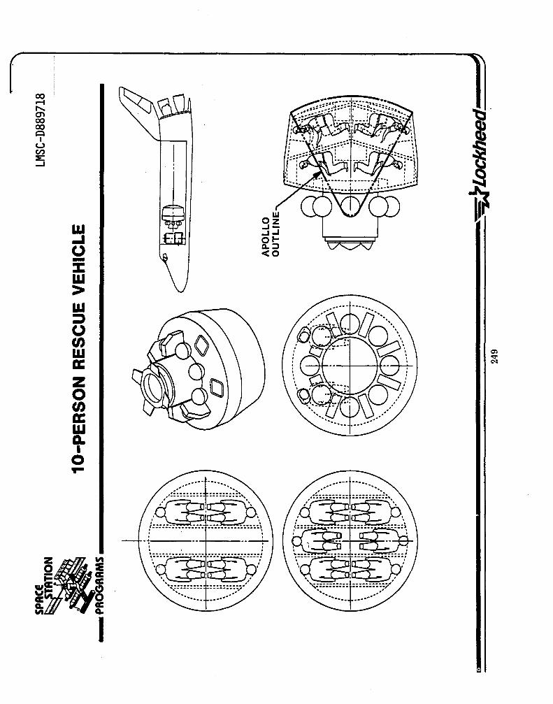
W -I o -:c w > W J o o w a: z o o a: w Q. I
o ... .,:::.: .... :.1":::::::,.
i;~:ID;\
LLI OZ -1--1-1 otQ.:::J <0
, . , . , , -t----.. ---t-
\~~':':':':': .. : ... --..... ~ ............. :::::~j .. . ,
··············t' ............. . ~~-.. ----- --------~~ --................ ---------

LMCS-D889718
OTV RESCUE CONCEPT (CONTINUED)
An alternative configuration using storable propellants is shown in the chart on the facing page. The propellant load has increased to 115,000 lbs and the delta V available has dropped, by 1,500 feet per second, but this system still has the capability to launch to almost any location at any time. It has the advantage that the storable propellants avoid the restraints imposed by long term storage of cryogens on orbit.
250

SPACE 24KLB PAYLOAD - ONE-WAY TRANSFER
REUSABLE OTV STORABLE PROPELLANT (lSP:340)
LMSC-D889718
• ___ PROGRAMS __________________________________________________________ __
,'- -.,~--;----'" \
#----'\" "\ , ", "\ .t.. ','.. .. } 'I' ~ " , I '" , ~, -.. ". '# ,
" 'f' " \.111' "--,, "n\ I ." lUll
~f--iI<-t--: -~: -:-~: :::: I'" I "" ' __ II .. UJ' " ,.. , " ,",
" 'I, ,'I, I' :,'
, ", II I , II' II. I
~----:,'" !---,'.!",' "-.r~"--
PAYLOAD PROPELLANT INERT WEIGHT AEROBRAKING INTERSTAGE
24,000 LB
INCL IN P/L
SECOND STAGE
57,570 LB 5,000 3,000
o
?51
FIRST STAGE
57,570 LB 5,080
o 320
AV (KFPS) _ STAGE ASCEN~ RETt.t.<N
ONE-WAY OTV
FIRST
SECOND
TOTAL
5.2
11.2
16.4
o o
FIRST STAGE RETURN
FIRST 4.0 4.0
SECOND 11.2 0
TOTAL 16.0
BOTH STAGE RETURN *
FIRST 4.0 4.0
SECOND 10.4 3.0
TOTAL 15.2
*SECOND STAGE RETURNS TO SHUTTLE-COMPATIBLE ORBIT

LMSC-D889718
OTV RESCUE CONCEPT
By using two centaur OTVs in tandem with aerobraking on the second stage OTV a delta V of 18,000 feet per second can be obtained. If propellant is retained in the first and second stage to allow the first stage to return to the station and to allow the second stage to return to a 220 nautical mile orbit for later pick-up by the space shuttle, the delta V of the system is reduced to 16,500 feet per second. This is still adequate to reach any LEO position from any space station location, provided aerobraking is used as indicated.
252

SPACE LMSC-D889718
24K LB PAYLOAD - ONE-WAY TRANSFER • ___ PROGRAMS __________________________________________________________ __
PAYLOAD PROPELLANT INERT' WEIGHT AEROBRAK ING INTERSTAGE
REUSABLE CENTAUR-TYPE OTV CRYOGENIC PROPELLANT (lSP = 440)
\. ! .... :
24,000 LB
INCL IN P/L
SECOND STAGE
45,000 LB 6,640 3,000
o
- .. --.. --.. --.
: ....
.. I" .'
FIRST STAGE
45,000 LB 6,640
o 360
!::.V (K FPS) STAGE ASCENT RETURN
ONE-WAY OTV
FIRST
SECOND
6.0
12.0
TOTAL 18.0
o o
FIRST STAGE RETURN
FIRST 5.4 5.4
SECOND 12.0 0
TOTAL 17.4
BOTH STAGE RETURN·
FIRST 5.4 5.4
SECOND 11. 1 3.0
TOTAL 16.5
·SECOND STAGE RETURNS TO SHUTTLE-COMPATIBLE ORBIT

LMSC-D8897l8
GEO SATELLITE RESUPPLY
A block diagram of activities required to resupply a GEO satellite is presented on the facing page. Initial satellite servicing missions for GEO satellites will likely be limited to resupply of consumables to extend system life. As capabilities for remote operations evolve, the sophistication of on-orbit servicing in GEO will grow.
Satellite systems such as MILSTAR could use the fuel resupply capability in the early stages of space station operation. The present design and system approach on existing and currently planned GEO satellites do not account for servicing. A change in approach and/or block 1 modification type effort to satellite design is required before an effective GEO satellite servicing option can be developed.
254

LMSC-D889718 SPACE
• ... PROGRAMS __________________________________________________________ ___ GEO SATELLITE RESUPPLY
ENSURE STA STA ASSEMBLES OTV FUELED AND OTV IS LAUNCHED RESERVE OF FUEL lOX r--- OTV AS REQUIRED AND -. READIED FOR -. TO DESIRED r-AND PRESSURANT FOR PERFORMS CIO AND LAUNCH FROM
GEO LOCATED SIC SAFING STA ALT/INCL
OTV DOCKS WITH OTV AND SIC SAFING OTV XFERS FUEL -. OTV RENDEZVOUS r--- SIC AND COMPLETES -. AND INTERFACE -. AND OX TO r-WITH SPACECRAFT UTILITIES IIF COMPATIBILITY
CONNECTION VERIFIED SPACECRAFT
-- OTV TO SIC ~
OTV UNDOCKS FROM ~ OTV STATION KEEPS r-. REMOTE C 10 OF
UMBILICAL DEMATED SIC AND VERIFIED WITH SIC SIC CONDUCTED -
OTV REMOTELY OTV RENDEZVOUS OTV IS SAFED AND -. CHECKED OUT FOR ....... OTV RETURNS r---- WITH STA; AND RMS r---- RESIDUAL PROD. -STATION RETURN TO STA CAPTURES IBERTHS PURGED
OTV TO STA
OTV IS CHECKED OUT RMS XFERS i.....+ AND PREPARED FOR r--- OTV TO INTERIM
INTERIM STOWAGE STOWAGE AREA

OPERATIONAL SUPPORT MATRIX FOR GEO SATELLITE RESUPPLY
LMSC-D8897l8
The use of the space station to support GEO satellite servicing imposes certain requirements on the station as shown on the facing page. These requirements are essentially identical to those imposed by satellite servicing for LEO systems and thu~ there are no conceptual or generic changes required to the space station for this activity. One operational constraint is that the propellant required for one-way transfer of a large payload taxes the capability of existing OTV systems. Thus a roundtrip mission can be envisioned if the payload (e.g., propellant resupply) 1s comparatively small. A one-way mission would be used if a payload the size of the ITSS space-based radar were to be launched to GEO.

SPACE OPERATIONAL SUPPORT MATRIX
GEO SATELLITE RESUPPLY
LMSC-D889718_ ___ _ __ _
• ... PROGRAMS __________________________________________________________ __
STATION NEEDS
..
OPERAT IONAL SUPPORT FUNCTION
1. FUEL TANKAGE
2. OXIDIZER TANKAGE
3. PRESSURANT TANKAGE
4. PROP IPRESS XFER SYS
5. AIRLOCK IXFER TUNNEL
6. OTV CAPTURE DEVICE
7. BERTHING PLATFORM
8. DOCKING UNIT
9. STAGE ASSY FACILITY
10. ON-BOARD CIO SYSTEM
11. MANIP C/O-BASE UNIT
12. EVA AIDS/XLATION TECH
13. OTV AND SIC LAUNCHI OPS CONTROL
• ,
• • • • • • • • • • • • • • • • •• •

KEY TECHNOLOGY ISSUES FOR STATIONBASED SATELLITE SERVICING
LMSC-D8897l8
Several technology issues require attention during development of the space station. These issues are highlighted on the facing page. There are no technological problems that would prevent the use of space station for satellite servicing. Exploration and development of the concepts shown.in this section will greatly benefit. however. from further advances in the technologies shown on the facing page. A few areas ~OTV Aerobraking. Crew Rescue Vehicle) require significant development activity before certain missions can be considered for space station.
258

SPACE lMSC-D889718
KEY TECHNOLOGY ISSUES FOR STATION-BASED SATELLITE SERVICING • ___ PROGRAMS ________________________________________________ ___
• DESIGN OF SPACECRAFT FOR SERVICING • SERVICING HARDWARE DEVELOPMENT • DESIGN FOR ON-ORBIT REFUELING
SHUTTLE DEMONSTRATION SATELLITE/OTV DEMONSTRATION
• DEVELOPMENT OF REUSABLE OTV • DEVELOPMENT OF OTV AEROBRAKING SYSTEM
AERO THERMO DYNAMICS STRUCTURES MATERIALS G & C
• DEVELOPMENT OF DEBRIS CAPTURE/HANDLING HARDWARE • DEVELOPMENT OF 10-MAN REENTRY VEHICLE
259

LMSC-D8897l8
CONCLUSIONS
The space station will provide a beneficial and cost-effective support base for on-orbit servicing of spacecraft and payloads. Note that existing OTVs have the capability to support space-based servicing, even for missions requiring transfer of large. payloads through trajectories involving substantial delta V. The space station is an excellent base for storing dormant satellites for launch on short notice to replace operational satellites that have failed. The station is also an excellent base for supporting a Shuttle crew rescue vehicle which will enhance the overall safety of the Space Shuttle system.
Consideration of spacecraft servicing requirements must be given careful attention in the early phases of space station design to ensure that proper capability is developed for this important function. Of equal importance, however, is the need to design spacecraft so they can be serviced on-orbit from either space station or Space Shuttle.
260

SPACE LMSC-D88971M
• ___ PROGRAMS __________________________________________________ __ CONCLUSIONS
1. SPACE STATION CAN PROVIDE A BENEFICIAL AND COST-EFFECTIVE FUNCTION IN SPACECRAFT AND PAYLOAD SERVICES
2. CONSIDERABLE TECHNOLOGY AND ASSOCIATED APPROACHES EXIST FOR DESIGN OF SPACECRAFT FOR ON-ORBIT SERVICING/MAINTENANCE
3. DESIGN FOR ON-ORBIT MAINTENANCE IS GENERALLY NOT CONSIDERED EARLY ENOUGH IN THE PROGRAM IMPLEMENTATION CYCLE
4. PRIMARY CONCERN IN DESIGN FOR MAINTENANCE IS STANDARDIZATION
5. THE ISSUE OF 'SPARES' CONTINUES TO BE A PROGRAM LEVEL PROBLEM
6. IT IS NOT TOO EARLY TO BEGIN DEVELOPING AN ORBITAL MAINTENANCE CONCEPTCS) FOR SPACE STATION
261


TASK 1-MISSION REQUIREMENTS 1.1 USER ALIGNMENT PLAN 1.2 SCIENCE AND APPLICATIONS
- PHYSICAL SCIENCES - LIFE SCIENCES
1.3 COMMERCIAL 1.4 U.S. NATIONAL SECURITY 1.5 SPACE OPERATIONS 1.6 REQUIREMENTS FROM USER NEEDS 1.7 FOREIGN CONTACTS
Vl m n -i o Z -A . 0"1

LMSC-D8897l8
REQUIREMENTS SOURCES
Th~ primary source of Space Station of requirements is the user needs. Requirements are also imposed' by the nature of operations to be conducted and by the infrastructure elements with which the station must interface. The chart on the right illustrates source categories of requirements. These categories cover both the requirements that are imposed on the station itself, and those that result from interfaces with the STS elements flight and ground communications, etc.
264

SPACE LMSC-D889718
REQUIREMENTS SOURCES • ... PAOGRAMS ____________________________________________________ __
STS INTERFACES
MANNED SPACE STATION REQUIREMENTS

LMSC -0889718
REQUIREMENTS DEFINITION
Definition of user requirements was initially based on the existing data base. This. source of information, though limited, was useful 1n the science and applications area.
New, up to date sources of user requirements were necessary in all areas, but particularly in the commercial, national security and operations categories. Extensive personal contacts with users generated some, but a very limited number of "hard requirements" for the space station. For this reason specific mission scenarios were developed to provide a focus for definition of specifics. This approach was the most fruitful in terms of defining specific requirements from user needs.

LMSC-D889718 SPACE
• _·PROGRAMS ________________________ _
REQUIREMENTS DEFINITION
• EXISTING DATA BASE
• USER CONTACTS
• MISSION SCENARIO DEVELOPMENT
2117

LMSC-D8897l8
MANNED SPACE STATION FUNCTIONS
Our user contacts resulted in a set of functions that must be accomplished by a manned space station either on the station itself or on a station controlled platform/free flyer. It is the functions that must be performed that determine requirements. The adjacent chart lists those broad categories of functions that lead to requirements.
268

LMSC-D889718
SPACE
MANNED SPACE STATION FUNCTIONS • ... PROGRRMS __________________________________________________ __
I
I
I
I,
I
I
SUPPORT FOR LONG DURATION PAYLOADS THAT NEED DIRECT MANNED INTERVENTION SUPPORT MANNED SPACECRAFT THAT NEED PERIODIC MANNED INTERVENTION
(ASSEMBLY, EXPERIMENT CHANGEOUT)
ORBIT PLACEMENT AND RECUVERY OF PAYLOADS
SUPPORT ORBIT STAGING, LAUNCH AND RECOVERY OF FREE FLYERS
TEST BED FOR DEVELOPMENT OF SENSORS, TECHNIQUES, SUPPORT SYSTEMS LOGISTICS SUPPORT INTERFACE WITH STS

LMSC-D8897l8
BASIC SPACE STATION FUNCTIONAL REQUIREMENTS
Based on our extensive contacts with potential Space Station users, a number of functional requirements surfaced, While these are general in nature they tended to be brought up frequently and must be considered to be prerequisites for any Space Station concept or architectural configuration.

LMSC-D889718
SPACE
• ___ PROGRAMS __________________________________________________ _ SPACE STATION FUNCTIONAL REQUIREMENTS
SPACE STATION MUST PROVIDE FOR: • PERMANENT MANNED HABITATION • CAPABILITY FOR LONG DURATION, LOW EARTH ORBIT OPERATIONS • ON ORBIT STATION ASSEMBLY VIA STS INTERFACE • ON ORBIT LOGISTICS SUPPORT VIA STS • DATA TRANSFER/COMMUNICATION LINKS WITH ORBIT-TO-ORBIT AND ORBIT-TO-GROUND
INTERFACES
• CAPABILITY TO SUPPORT PAYLOADS (MULTI DISCIPLINE, PERIODIC AND CONTINUOUS OPERATIONS)
• CAPABILITY FOR GROWTH (FUNCTIONS AND OPERATIONS) • COMPATIBILITY WITH STS INFRASTRUCTURE • COMPATIBILITY WITH DOD INFRASTRUCTURE
271

LMSC-D889718
MISSION SUPPORT REQUIREMENTS
Each Space Station mission scenario was analyzed to determine requirements that might be readily accomplished on the Space Station. From these requirements were developed the Mission Support Requirements, i.e., the capability the space station would need to provide in order to s~ccessfully fulfill the mission requirements. In many cases these support requirements have been included in the scenarios contained in Attachment 2, Vo 1 ume 1.
This series of 14 charts list the principal drivers that will influence space station architecture - crew size, power requirements, support, environment, EVA and manned interaction as well as orbit parameters. Based on these drivers and needs identified by users, generic types of space stations were established for each of the missions (scenarios). These ranged from manned modules to attached laboratories and platforms, both attached and free flying. These broadly identified requirements were an input to Task 2, Mission Implementation Concepts in which space station architectural concepts were developed.
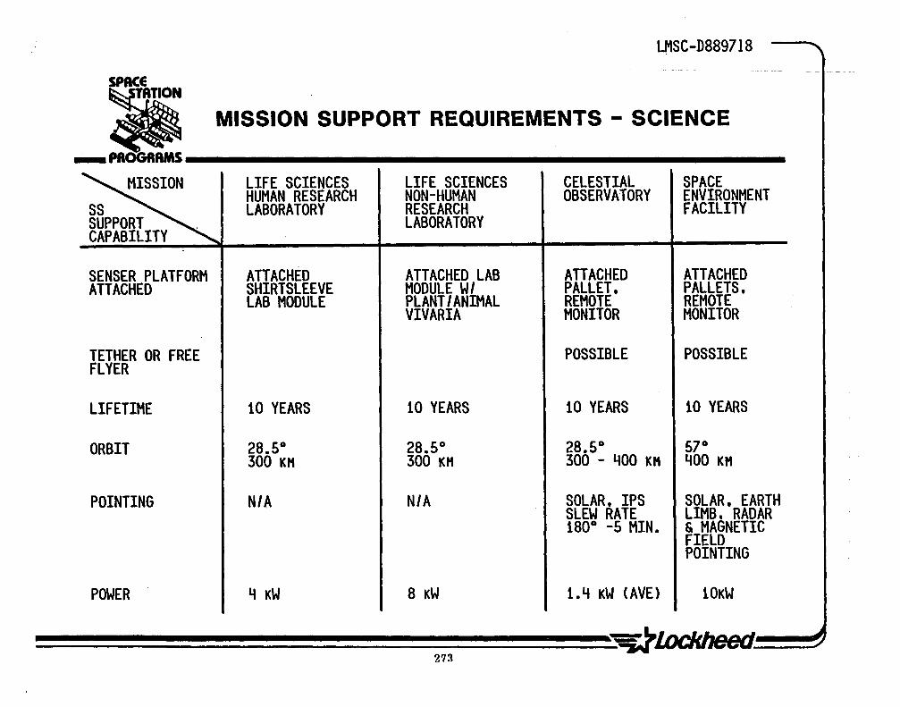
LMSC-D889718
SPACE
• MISSION SUPPORT REQUIREMENTS - SCIENCE
_PROGRAMS
~ LIFE SCIENCES LIFE SCIENCES CELESTIAL SPACE HUMAN RESEARCH NON-HUMAN OBSERVATORY ENVIRONMENT
SS LABORATORY RESEARCH FACILITY SUPPORT . LABORATORY CAPABILITY
SENSER PLATFORM ATTACHED ATTACHED LAB ATIACHED ATTACHED ATTACHED SHIRTSLEEVE MODULE W/ PALLET. PALLETS,
LAB MODULE PLANT/ANIMAL REMOTE REMOTE VIVARIA MONITOR MONITOR
TETHER OR FREE POSSIBLE POSSIBLE FLYER
LIFETIME 10 YEARS 10 YEARS 10 YEARS 10 YEARS
ORBIT 28.5° 28.5° 28.5° 57° 300 KH 300 KH 300 - 400 KH 400 KH
POINTING N/A N/A SOLAR, IPS SOLAR, EARTH SLEW RATE LIMB. RADAR 180° -5 MIN. & MAGNETIC
FIELD POINTING
POWER 4 KW 8 KW 1.4 KW (AVE) 10KW
213 ~l.ockheed

LMSC-D889718
SPACE STATION EVOLUTION
Following the establishment of mission support requirements based on user contacts, mission implementation concepts were formulated for a four phase space station evolution. A modest capability was planned for 1990 with an expanded capability station in the late 1990's. An overview of this phasing is shown in the the adjacent chart. Subsequent charts define each phase, the details of which provided ground rules for completing tasks 2 and 3.
The evo1~tion was developed within guidelines that required staying rather general in trade studies and avoiding point design while still driving towards detailed user needs. General needs may be summarized as lower inclinations, LEO, general purpose initial station capability (due in part to a lack of specific knowledge of space environments), adaptability to an unknown real future, and a user friendly station.
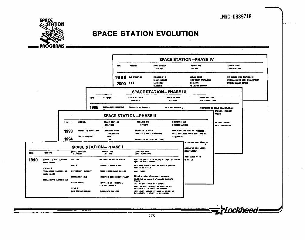
SPACE LMSC-D889718
• ___ ~ROGRAMS __________________________________________________________ __ SPACE STATION EVOLUTION
SPACE STATION-PHASE IV ,
,. IIISS'" II'<a ,...,.011 IIftCI$ ... --_as GPI'_ _._, ... 1988 --, ... r~e" -- .. , .1IIlIIIE ••• SI"_ ••
ucmQIIIU 1II0I1I1USI1'IIIfILS", IJI.,ICA&. .... " '.111 ~ amosr 2000 Cit UMZ(.w anaDIOO: SI ..... IIPIL' SfMB ._00: ... 11".1"...,.,....
SPACE STATION-PHASE III
'". ... ss .... SPACI StA .... ""ACtS All • CIMIl",S •••
'1I,.en .. " .. , CONSlHU"ON'
1995 _ ..... e. WN.L." 10_ "I~UII_ICII' ......... IODU 4IU uraal .. I!
'1_. -, SPACE STATION-PHASE II
WlSln
.. III "ISII" SPACI "nl" ._ACTS a..r e_"" ... "''''_011 n ... en OptiONS _IIH .... _ MIZ .... 1&I1d
1993 '&TELLITI IlIYle11lG _illIG rol. INCLOSE. 01 "11 I" IIIoCII IU CAlI II hftCID •
SPACae .. " '''lOCUS' _, .UUOlMS IILL PCLOSII _, SU .. ONS I'
or. SlIflC11IG or. llQUIIE.'
1994 "" un., Of nnll'c or orrl ,. ro..- '01 SP.Ult
I
SPACE STATION-PHASE I 11111_.' "1 LOCAL
S'ACE sunOM , .... Ct. AlII Catealrs UI IS""t.OII' '''111 MnSIOII SUVIUS onto:.s CONSIH""ONS
'11 IAllCO II'"
1990 SCllOC' , '''LICUION ' .. I .. n IlUCLUI 01 SOUl _EI ... " II CA .. IU or USI'" UTMEI ...... ., 'UELI 1 .... IIIIII1S nl'"'' '"11 _sa.
-II II .... " ...... LAI .lnuAL LAUIICI. SIIS:)I '.II."'/""'TS .. I I' • ACcns TO SPAn
c_ee.'L 'IOCns." 'IPIIIII(III SU'POII '1II1I1nl ..... ' .ALLn .... n_. U"I.,,,,",S
_ICAUONS ISOLAn. II.ElI ... n .. LLlt u,um fNUr ___ ,
GPlutlOfilAL II'IIIIICI s.,1.s.:1" ... "~ I II 1dI5IJ.' 1\. ....... ·"UT 1 .. 1_, sl .... n 01 ''''GUL USE 0' IS& sraCi LA. IUIUA
C, .. e.,SULI NOlI CAl tUn.OIIles II UPIAU. oa IUO' 1,,1'111 .. ,. o'in at , .... LOll C.T.UIA'IGf '''UCE"" SI.UTII ... LOIeG' SHOULI If '"" , 1t·,.,1t
U .. IILln • ISlU"LI! IISasUII

LMSC-D889718
SPACE STATION EVOLUTION PHASES
Evolution of the space station system from an initial capability in 1990 to a significantly expanded capability ten years later has been divided into four generalized phases which characterize what the station system is capable of doing at poirits in time. Initially the station will begin with a single shuttle launch which will provide enough hardware to implement an R&D in space facility that can accomodate civil and 000 needs. This facility will be further enhanced by additional launches. A second phase adds propulsive capability by means of TMS and/or OTVls which allows satellite servicing and .our orbit assembly of larger structures to commence. A third phase expands the stations capability to handle deployment, retrieval and servicing of satellites in virtually all low or medium orbit locations. The fourth phase, near the end of the decade expands both commercial and 000 capabilities. It'could then include rescue vehicles a~d possibly multiple stations.
Evolution of the system though the four phases shown here will be accomplished though several steps of station implementation. Later in the presentation evolutionary steps are referred to in Task 2 discussions of architectural development. Those steps, many in number, show how station implementation meets the capabilities of the four evolutionary station phases.
276

LMSC-D889718 SPACE
EVOLUTION PHASES • ___ PROGRAMS __________________________________________________ ___
PHASE I
R&D LABORATORY - ACCOMODATES 000 AND COMMERCIAL USER AND SCIENCE EXPERIMENTS
PHASE II
ADDS OTV AND TMS CAPABILITY WHICH ALLOWS SUPPORT TO FREE FLYERS. SATELLITE SERVICING AND ASSEMBLY IN ORBIT
PHASE III
EXPANDS DEPLOYMENT AND SERVICING TO LARGE MULTI-SATELLITE SYSTEMS IN ALL LEO AND HEO APPLICATIONS
PHASE IV
EXPANDS COMMERCIAL. 000 OPERATIONS (C2) AND RESCUE VEHICLE. COULD BE MULTIPLE STATIONS
277

LMSC-D889718
CAPABILITY GROWTH
Space station capability growth based on the phasing described in the previous charts is depicted here. This growth is based on a 10 year development span (input to the study) and progresses in a logical sequence over that period. As the study progreised and details were developed in the Mission Implementation Concepts (Task 2), we found we could accelerate the capability growth to achieve the ·ultimate- space station by the 1996.to 1997 time period and still stay within the 'strawman· program funding.
278

LMSC-D889718 SPACE
CAPABILITY GROWTH • ___ PROGRAMS ________________________________________________________ ___
1990
14 2000
I ADVANCED I INITIAL CAPABILlTY-----.~ ... I .. -----EVOLUTION----........ e----CAPABILITY----t ....
~-------BASELINE· ~
15 kW \W. - - - - -2-3 MEN f
MANNED STATION ............
TELEOPERA TOR
FREE FLYING PLATFORMS
MANNED
~--- --
------~.--
ADDED MODULES
STATIONS .... ---.,
FREE FLYING PLATFORMS,
REUSABLE OTVs
CONTINUED MODULAR GROWTH
DEDICATED FACILITIES FOR
• COMMERCIAL
• SCIENCE
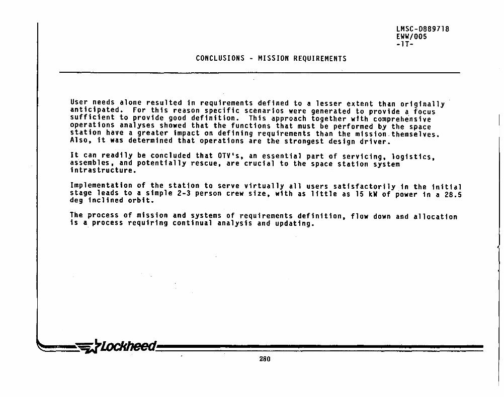
CONCLUSIONS - MISSION REQUIREMENTS
LMSC-D889718 EWW/005 -IT-
User needs alone resulted in requirements defined to a lesser extent than originally anticipated. For this reason specific scenarios were generated to provide a focus sufficient to provide good definition. This approach together with compreh~nsive operations analyses showed that the functions that must be performed by the space station have a greater impact on defining requirements than the mission. themselves. Also, it was determined that operations are the strongest design driver.
It can readily be concluded that OTVls, an essential part of servicing, logistics, assembles, and potentially rescue, are crucial to the space station system intrastructure.
Implementation of the station to serve virtually all users satisfactorily in the initial stage leads to a simple 2-3 person crew size, with as little as 15 kW of power in a 28.5 deg inclined orbit.
The process of mission and systems of requirements definition, flow down and allocation is a. process requiring continual analysis and updating.
280

SPACE LMSC-D889718
CONCLUSIONS MISSION REQUIREMENTS • ___ PROGRAMS __________________________________________________ _
• SPACE STATION FUNCTIONS DICTATE REQUIREMENTS MORE THAN MISSIONS • OPERATIONS ARE MOST SIGNIFICANT DESIGN DRIVER • OTVIS ARE ESSENTIAL ELEMENT OF SPACE STATION
- EXISTING OTVIS WILL PROVIDE AN IMMEDIATE CAPABILITY FOR CERTAIN MISSIONS
- ADVANCED OTV'S WILL SIGNIFICANTLY EXPAND CAPABILITY FOR REMOTE (TELEOPERATOR ACTIVITIES)
• INITIAL STATION IMPLEMENTATION: - POWER 13 - 15 KW
- 2-3 PERSONS - 28.50 INCLINATION - SINGLE SHUTTLE LAUNCH
?Rl


LMSC-D889718
~ -=.. PROGRAMS iiiiiiiiiiiiiiiiiiiiiiiiiiiiiiiiiiiiiiiiiiiiiiiiiiiiiiiiiiiiiiiiiiiiiiiiiiiiiiiiiiiiiiii...-J
TASK 1-MISSION REQUIREMENTS 1.1 USER ALIGNMENT PLAN 1.2 SCIENCE AND APPLICATIONS
- PHYSICAL SCIENCES - LIFE SCIENCES
1.3 COMMERCIAL 1.4 U.S. NATIONAL SECURITY 1.5 SPACE OPERATIONS 1.6 REQUIREMENTS FROM USER NEEDS 1.7 FOREIGN CONTACTS
(J) m n -f o z ... . "-I

LMSC-D8897l8
FOREIGN INFORMATION EXCHANGE
Four foreign companies signed agreements. SPAR of Toronto sent an engineer to work with us on the space station for 2 weeks. With the Europeans we have an information exchange agreement, dependent upon State Department approval. .
The European visit covered a broad range of companies, research institutes and government facilities. All of these have been involved in space exploration for some time; and they presently are engaged 1n numerous space research/flight projects.
284
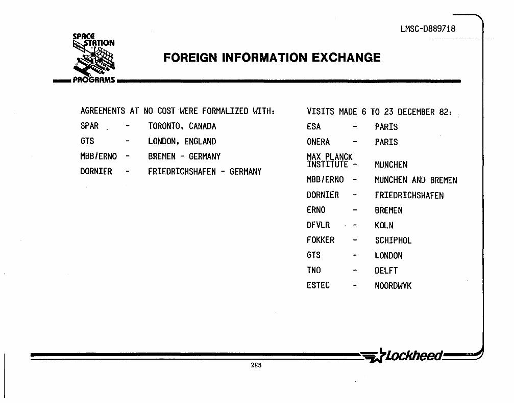
LMSC-D889718 SPACE
• ___ PROGRAMS __________________________________________________ __ FOREIGN INFORMATION EXCHANGE
AGREEMENTS AT NO COST WERE FORMALIZED WITH: VISITS MADE 6 TO 23 DECEMBER 82: SPAR TORONTO. CANADA ESA PARIS GTS LONDON. ENGLAND ONERA PARIS MBB/ERNO - BREMEN - GERMANY MAX PLANCK DORNIER FRIEDRICHSHAFEN - GERMANY
INSTITUTE - MUNCHEN MBB/ERNO - MUNCHEN AND BREMEN DORNIER FRIEDRICHSHAFEN ERNO BREMEN DFVLR KOLN FOKKER SCHIPHOL GTS LONDON TNO DELFT ESTEC NOORDWYK
LMSC-D889718
FOREIGN PARTICIPATION
To make the space station a truly international venture methods of allocating mission functions and dividing subsystems have to be devised. These subsystem separations must not let the total space station be put at risk. The most extensive and beneficial participation by other nations will be gained by including their top-priority mission and technology objectives. Contributions by other states should emphasize:
o Their leading technologies,
o A nation's patented or proprietary processes, designs, and hardware or software,
o Areas where they are giving top priority and committing substantial resources to forging breakthroughs and developing new markets, or
o Areas where they are anxious to broaden their technical base or enhance prestige in selected fields of science.
To minimize interference among the basic space s'tation,and auxiliary missions, whether foreign or domestic, the' following principles will help: .
o
o
Select mission and design alt~fnatives to eliminate or control risks of performance loss, program delay, or cost overruns '
Design auxiliary missions to allow operations and support as independent as possible from basic space station functions. This might involve separate C3 capabilities, data transmission through links with space station transparency, or various levels of system/experiment autonomy.
Examples of subsystems or configurations that can lower system interference hazards and program risks are rescue vehicles, TMS, personnel transporters, tethered systems and specialized free flyers.
286

LMSC-D889718 SPACE
• FOREIGN PARTICIPATION ... PROGRAMS __________________________________________________ ___
• TO DEVELOP THE SPACE STATION AS AN INTERNATIONAL VENTURE. PROMOTE INCLUSION OF OTHER NATIONS' DESIRED MISSIONS. TECHNOLOGIES. AND DESIGNS
• OTHER NATIONS' MAXIMUM INTEREST AND LEVEL OF CONTRIBUTIONS SHOULD EMPHASIZE A COUNTRY'S LEADING TECHNOLOGIES PARTS/MATERIALS/PROCESSES/DESIGNS PATENTED OR PRORIETARY PRIORITY DEVELOPMENTS TO COMMIT RESOURCES AND FORGE ADVANCES
LOOKING FOR BREAKTHROUGH DEVELOP NEW CAPABILITIES AND MARKETS
• MINIMIZE INTERFERENCE BETWEEN BASIC SPACE STATION AND AUXILIARY MISSIONS MINIMIZE SCHEDULE. COST. AND DESIGN UNCERTAINTIES INDEPENDENTLY OPERABLE AND SUPPORTABLE SEPARABLE. REMOVEABLE. REPLACEABLE INTERNALLY FAILSAFE. UNABLE TO CAUSE CRITICAL FAILURES IN STATION

LMSC-D8897l8
FOREIGN VISIT FINDINGS
Throughout these visits the Europeans had a unanimously enthusiastic behavior towards the prospects of a space station. However, without exception they stated a desire to be more involved than just as nuts and bolts manufacturers. They feel that being given the responsibility for a total space station subsystem would be more in line with their technical capability.
288

LMSC-D889718 SPACE
• ___ PROGRAMS __________________________________________________ _ FOREIGN VISIT FINDINGS
• EUROPEANS ENTHUSIASTIC ABOUT SPACE STATION • FINDINGS OF ESA STUDY ABOUT SAME AS LOCKHEED STUDY • EUROPEANS WANT RESPONSIBILITY FOR TOTAL S.S. SUBSYSTEM • CAPABLE AND WILLING TO BUILD ANY PART OF SPACE STATION
289


tl'ISC-D889718
r=. PROGRAMS iiiiiiiiiiiiiiiiiiiiiiiiiiiiiiiiiiiiiili_iiiiiiiiiiiiiiiiiiiiiiiiiiiiiiiiiiiiiiiiiiiiiiiiil
TASK 2-MISSION IMPLEMENTATION CONCEPTS
2.1 MISSION SCENARIO ANALYSIS AND ARCHITECTURAL CONCEPTS
2.2 ALTERNATIVE SYSTEMS CONCEPTS 2.3 MISSION OPERATIONS
. ARCHITECTURAL DEVELOPMENT 2.4 ARCHITECTURAL ANALYSIS TRADES 2.5 EVOLUTION . 2.6 CONFIGURATION 2.7 TECHNOLOGY DEVELOPMENT 2.8 CONCLUSIONS

LMSC-D889718
MISSION IMPLEMENTATION CONCEPTS AND OBJECTIVES
The objectives of this part of the study are to define space station system concepts in terms of functional architecture and configuration that will accommodate the projected mission requirements for the 1990 to 2000 era, and to define evolutionary steps to implement the system.
The terminology used throughout this part of the study is as follows:
• Space station - a manned assembly in low earth orbit (LEO) • Space station system - space station element and other operating payload,
experiment, and support elements • Exeeriment - a collection of hardware designed to achieve a single investigative
obJective • Payload - a grouping of multiple experiments designed to achieve a major
objective, either single purpose or multipurpose • Configuration - a pictorial structural arrangement of major hardware that
depicts a space station • Attached payload or experiment - physically attached to space station • Detached payload or experiment - physically separated from space station; may be
in orbit alone or tethered to space station . • Free flyer - a vehicle in orbit alone, may have single or multiple payloads or
experiments • Satellite or spacecraft - a single mission vehicle in orbit alone • Platform - an unmanned assembly in separate orbit • Support elements - major interfacing operational elements of the total space
infrastructure consisting of the space communication satellites (TDRSS, MILSATCOM); ground-based tracking, communications, and control; and the Space Transportation System (STS) launch base and Shuttle vehicle
• Orbit trans orters/services - teleoperator maneuvering system (TMS) and orbit trans er vehlC e V
292

SPACE
• MISSION IMPLEMENTATION
CONCEPTS OBJECTIVES
LMSC-D889718
... PROGRAMS ________________________________________________ __
TO IMPLEMENT MISSION REQUIREMENTS FOR 1900 - 2000 ERA
• DEFINE AND ANALYZE A RANGE OF ALTERNATIVE SYSTEM CONCEPTS TO MEET MISSION AND SATISFY OPERATIONAL REQTS.
• DEVELOP AND ANALYZE ARCHITECTURAL OPTIONS
• DEFINE A PLAN FOR EVOLUTION OF SPACE STATION
LMSC-D889718
SPACE STATION SYSTEM INFRASTRUCTURE AND TOTAL SYSTEM ARCHITECTURE
An abbreviated overview of the basic station infrastructure is illustrated on the facing page. This architectural overview does not include classified U.S. national security elements; however, the infrastructure is highly applicable at the element level. A strong case is made for the natural and progressive evolution of the station using the basic Space Transportation System (STS) as the stepping stone to achieve a smooth tra~sition and cost-effective implementation.
An important element of the infrastructure, which to date appears to have received less emphasis but is highly important, is the integrated logistics support (llS) element of the overall station infrastructure. Both nominal and emergency IlS factors must be considered very early in the station concept development sequence as they can substantially affect the basic station and support element architecture. Pivotal also is the inherent heed for an orbital transport system capability that is key to servicing and spacecraft positioning scenarios and associated mission needs. Communication is also an extre' ~ly important element and the basic issue of station autonomy versus'ground support will be a key trade study and system and subsystem architectural impact and driver.

SPACE LMSC-D889718
aSTAT.ION
SPACE STATION SYSTEMS INFRASTRUCTURE & TOTAL SYSTEMS ARCHITECTURE ... PROGRAMS __________________________________________________________ __
STS & ASSOCIATED ELEMENTS FORM A NATURAL PROGRESSIVE STEPPING STONE FOR SPACE STATION IMPLEMENTATION
STS ELEMENT
295
SPACE COMM ELEMENT
LOGISTICS ELEMENT


SPACE
• r-=.. PROGRAMS iiiiiiiiiiiiiiiiiiiiiiiiiiiiiiiiiiiiiiiiiiiiiiiiiiiiiiiiiiiiiiiiiiiiiiiiiiiiiiiiiiiiiiiiiiiiiiiiiiiiiiiiiiiiiiiiiiiiiiiiiiiiiiiiiiiiiiiiiiiiiiiiiiiiiiiil
TASK 2-MISSION IMPLEMENTATION CONCEPTS
2.1 MI"SSION SCENARIO ANALYSIS AND ARCHITECTURAL CONCEPTS
2.2 ALTERNATIVE SYSTEMS CONCEPTS 2.3 MISSION OPERATIONS
ARCHITECTURAL DEVELOPMENT . 2.4 ARCHITECTURAL ANALYSIS TRADES 2.5 EVOLUTION 2.6 CONFIGURATION 2.7 TECHNOLOGY DEVELOPMENT 2.8 CONCLUSIONS
lJ) m n -f o Z 'N . ....
LMSC-D889718
APPROACH TO DEFINING MISSION IMPLEMENTATION CONCEPTS
The basic approach to the station architectural development study effort is portrayed on the facing page. Certainly, the effort was substantially influenced by the user needs and requirements developed in Task 1 of this study. Significant effort in Task 1 was also given to development of the set of mission scenarios that formed the basis of the operation/function analyses then conducted. A number of scenario operation/function flow diagrams were prepared from which a basic set of architectural concept definitions were developed. Data sheets indicating station subelement characteristics were then generated which, in concert with the aforementioned information provided by the basic data base, were used in the architectural development activity.
A wide range of architectural station concepts were prepared and evaluated as to potential practicality, feasibility, mission suitability, cost, and support potential. Simultaneously, top-tier requirements and general assumptions were then prepared for subsequent design activity. Also concurrently, basic station support functions and interface needs were delineated for operational criteria input. Architectural review and assessment criteria were prepared for use in subsequent examination of the proposed set of station alternative concept approaches. Initial sketches of the cadre of station candidate concepts were prepared and screened according to previously prepared criteria. Again, top-tier requirements 'were imposed and several performance and feasibility trades conducted. Rationale for station evolution was defined and applied to the more promising candidate station concepts. Concurrently, costing analyses were conducted relative to the more viable station concept(s} to further substantiate the evolutionary approach and to support the reference initial and full-up station concept configuration.
~~~~~~~~~~~~~~~~~~~ 298

SPACE LMSC-D889718
• ' APPROACH TO DEFINING MISSION _PROGRAMS ____ �M_P_LE_M_E_N_1:_'I4_~_IO_N_C_O_N_C_E_P_T_S _ ______ _
DETERMINE USER CONDUCT DELINEATE NEEDS , OPS IFUNCTIONS r- OPS - SUBSETS
REQUIREMENTS ANALYSES (FUNCTIONS)
t t • IDENTIFY' IDENTIFY PREPARE DEVELOP CANDIDATE PREPARE BLOCK
DEFINE BASIC -. OVERALL OPS r-- FUNCTION FLOW !- STATION CONCEPT !- DIAGRAMS OF MISSION SCENARIOS SET DIAGRAMS CATEGORIES CONCEPT CATEGORIES
I I I DEVELOP SELECTED t
SCENARIO CANDIDATES PREPARE STA. SUB ELEMENT
DATA SHEETS -I'.'NTO" 'C",'Am""~ STA. SUBELEMENTS
11 t DEV.ARCH.APPLICATION REQTS. , OPTIONS
PREPARE CONCEPT PREPARE CONCEPT PREPARE 1st SET OF DEV. STATlON!s) SKETCHES OF STA. r-- SKETCHES OF ALT.STA. SCREENED ALTERNATIVE !- EVOLUTION
SUBELEMENTS SUBELEMENTS CONCEPT SKETCHES APPROACHES DEV.ARCH.REVIEW ,
ASSESSMT.CRIT. , APPLY
f f PREPARE SKETCHES OF CONDUCT TOP-TIER EVAL.GENERAL CONDUCT
STATION SUPPORT' SYS.PERFORMANCE PERFORMANCE COST BENEFIT INTERACTIVE I/F. , FEASIBILITY TRADES CAPABILITY ANALYSES

LMSC-D889718
MISSION IMPLEMENTATION SCENARIOS
Fifteen mission description scenarios developed from results of user surveys and evaluation of projected NASA and 000 mission models in Task 1 of this study are shown here. Detailed mission descriptions are included in Attachment 2, Volume I. These scenarios are representative of the range of missions in the science, applications, commercial, U.S. national security, and space operation categories anticipated for the 1900 to 2000 era.
Each scenario is analyzed to develop functional sequences and to identify functional support requirements. Functions are grouped in significant sube1ements to define a system architecture and to identify major interfaces. From the defined functions and interfaces, the role and attributes of the space station are defined to implement each mission.
Two of the seven missions listed for space operations were analyzed in detail, scenario 14 (On-Orbit Satellite Servicing) and scenario 15 (Large Structures Assembly). An overview evaluation of the other five missions for astronomy platform support, space telescope maintenance, prompt satellite replacement, Shuttle crew rescue vehicle, and GEO satellite resupply, has shown that the space station attributes to accommodate these five missions are essentially satisfied by those attributes identified for scenarios 14,and 15. A discussion of these space operation missions is given in Task 1.1.4.
300
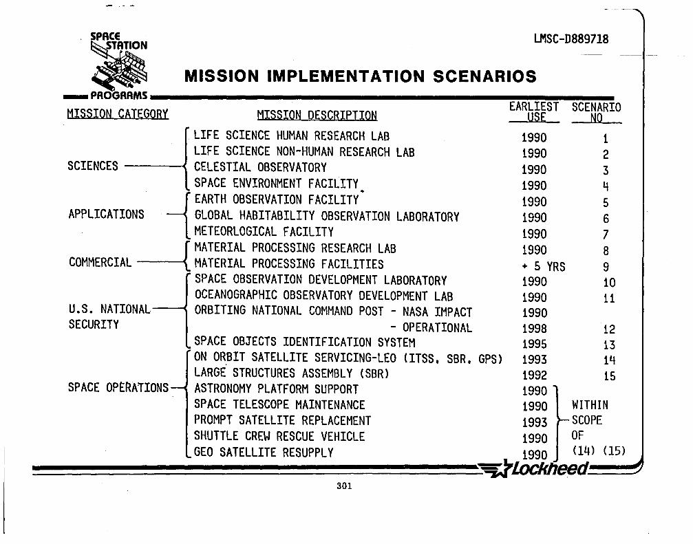
. SPACE LMSC-D889718
MISSION IMPLEMENTATION SCENARIOS • ---PROGRAMS--------------------------------------~E~A~RL~I~ES~T~S~C~EN~A~RI0 MISSION CATEGORY MISSION DESCRIPTION USE NO
LIFE SCIENCE HUMAN RESEARCH LAB 1990 1 LIFE SCIENCE NON-HUMAN RESEARCH LAB 1990 2
SCIENCES --~ CELESTIAL OBSERVATORY 1990 3 SPACE ENVIRONMENT FACILITY 1990 4 .
-1 EARTH OBSERVATION FACILITY 1990 5 APPLICATIONS, GLOBAL HABITABILITY OBSERVATION LABORATORY 1990 6
METEORLOGICAL FACILITY 1990 7 r MATERIAL PROCESSING RESEARCH LAB 1990
COMMERCIAL -------tMATERIAL PROCESSING FACILITIES + 5 YRS SPACE OBSERVATION DEVELOPMENT LABORATORY 1990 OCEANOGRAPHIC OBSERVATORY DEVELOPMENT LAB 1990
U.S. NATIONAL---< ORBITING NATIONAL COMMAND POST - NASA IMPACT 1990 SECURITY - OPERATIONAL 1998
SPACE OBJECTS IDENTIFICATION SYSTEM 1995 ON ORBIT SATELLITE SERVICING-LEO (ITSS. SBR. GPS) 1993 LARGE STRUCTURES ASSEMBLY (SBR) 1992
SPACE OP~RA1IONS ASTRONOMY PLATFORM SUPPORT 1990
8 9 10 11
12 13 14 15
SPACE TELESCOPE MAINTENANCE 1990 WITHIN PROMPT SATELLITE REPLACEMENT 1993 SCOPE SHUTTLE CREW RESCUE VEHICLE 1990 OF GEO SATELLITE RESUPPLY 1990 (14) (15)
~~~~~~~~~~~~~~~~~~~eed~~ 301

LMSC-D889718
SCENARIO ll--OCEANOGRAPHY OBSERVATORY DEVELOPMENT LABORATORY--MISSION FUNCTIONAL SEQUENCE
The objective of this mission is to provide a development laboratory and testbed in space where sensor instru~ents, systems, and operating procedures intended for use in ocean surveillance can be developed and evaluated. By means of direct crew scientist hands-on interaction with breadboard and development equipment, the. operational characteristics and man's role in controlling sensor targeting and interpreting sensor data can be evaluated.
The functional sequence to position and operate an oceanography observatory development laboratory in LEO is shown here.
302

. ,
SPACE LMSC-D889718
OCEANOGRAPHY OBSERVATORY DEVELOPMENT LABORATORY MISSION FUNCTIONAL SEQUENCE • ... PROGRAMS __________________________________________________________ __
SCENARIO 11
ON GROUND LAUNCH AND ASSEMBLE EQUIPMENT PREPARE EQU IPMENT ~ TRANSPORT EQUIPMENT --- IN LABORATORY
FOR LAUNCH :rO LOW EARTH ORBIT AND ON PALLET
I , CHECKOUT AND RETURN TRANSPORT READY SYSTEMS ~ TRANSPORT --- PERSONNEL & SUPPLIES·
FOR USE TO EARTH EARTH TO OBSERVATORY
I , READY SENSORS ORIENT AND OBSERVE, COLLECT
AND r--- PROGRAM SENSOR --- AND ANALYZE PERSONNEL TO VIEW ANGLES SENSOR DATA
PERFORM OBSERVATIONS
I , - ... MODIFY AND EVALUATE PERFORM SCHEDULED COMMUNICATE AND SENSOR SYSTEMS AND UNSCHEDULED RELAY DATA ---+ AND PERSONNEL ~ MAINTENANCE ON
TO EARTH I NTERACT ION SYSTEMS
I , REPLENISH CONDUCT CONTINUOUS
EXPENDABLES t---- MAINTAIN AND ADJUST ~ OBSERVATIONS OF ~ AND FLIGHT TRAJECTORIES EARTH OCEANS
PERSONNEL

LMSC-D889718
SCENARIO ll--OCEANOGRAPHY OBSERVATORY DEVELOPMENT LABORATORY ARCHITECTURAL CONCEPT
The system architecture for the oceanography observatory development laboratory is shown here. An enclosed laboratory-type module in combination with an open-faced experiment pallet is directly coupled to the basic space station subelements. This permits personnel to perform hands-on interaction with experiments in the laboratory and remote interaction with experiments on the pallet. The STS provides direct support to initially transport the laboratory module, pallets, and experiments to LEO and to continue logistics support for consumables, crew scientist rotation, and experiment modifications during mission lifetime. Data evaluation is conducted on board the space station, and data are transmitted to the ground data systems via the space station to ground communication link.
Functions of the system architecture are presented below:
Module 1. Habitation 2. Laboratory
3. Experiment pallet 4. Power and control
5. Communication and data system
6. Docking/berthing
7. Logistics 8. Ground communication and data
9. STS
Functions Llvlng and maintenance of crew Hands-on experiment, sensor setup and
operations Remote experiment, sensor testbed Electrical power, attitude stabilization, and
control Voice and data link, data evaluation, and
display Docking/berthing for Shuttle; transfer
personnel, equipment, and supplies Storage for facility and payload supplies Tracking, voice/data communication, and data
distribution Shuttle ground to space transport, resupply
logistics
304

LMSC-D889718 SPACE
OCEANOGRAPHY OBSERVATORY DEVELOPMENT • LABORATORY ARCHITECTURAL CONCEPT ... PROGRAMS _______________________________________________________ __
SCENARIO 11
HABITATION MODULE
LABORATORY MODULE
EXPERIMENT PALLET
POWER &
CONTROL MODULE
COMMUNICATIONS &
DATA SYSTEM MODULE
GROUND COMMUNICATION
& DATA SYSTEM
LOGISTICS MODULE
DOCKINGI BERTHING
STS

SCENARIO ll--ROlE OF SPACE STATION TO SUPPORT OCEANOGRAPHY OBSERVATORY DE VEl OPMFNT lABORATORY
LMSC-D889718
The space station provides direct, continuous, long-term support to the oceanography observatory development laboratory mission. The station provides online direct electrical power and environmental interfaces and supports on board data analysis and conferencing communications and data transfer to the ground. Direct EVA-type support is provided to service and maintain experiments mounted on the open pallet. laboratory equipment maintenance and service and consumable replenishment are conducted continuously.
Space station attributes to support this mission are shown here.
30a

LMSC-D889718 . SPACE
.'
STATION ROLE OF SPACE STATION TO SUPPORT OCEANOGRAPHY
OBSERVATORY DEVELOPMENT LABORATORY _PROGRAMS ElIw, _____________________ _
SCENARIO 11
ATTRIBUTES
• PROVIDE LONG-DURATION HABITATION FOR PERSONNEL • PROVIDE SHIRTSLEEVE INTERACTIVE "HANDS ON" LABORATORY • PROVIDE REMOTE INSTRUMENTATION/SENSOR TESTBED • PROVIDE ELECTRICAL POWER AND DATA/COMMUNICATIONS INTERFACE • PROVIDE VOICE AND DATA LINK TO GROUND • PROVIDE ALTITUDE AND ATTITUDE ORIENTATION • PROVIDE PERIODIC REPLENISHMENT OF EXPENDABLES AND PERSONNEL • PROVIDE SCHEDULED AND UNSCHEDULED MAINTENANCE • PROVIDE DOCKING AND OPERATIONAL INTERFACE WITH STS

LMSC-D889718
SCENARIO l--ROLE OF SPACE STATION TO SUPPORT HUMAN RESEARCH LABORATORY
The" space station provides direct, continuous, long-term support to the human research laboratory mission. The subjects can be crewmembers or special subjects housed in the habitation module. The station provides direct power and environmental interfaces and supports onboard data analysis and conferencing communication and data transfer to the ground. Equipment maintenance, service, and exchange is conducted continuously.
Space station attributes to support this mission are shown here.
308

SPACE
~.ION LMSC-D889718
~ ROLE OF SPACE STATION TO SUPPORT _ PROGRAMS ____ H_U_M_A_N_R_E_S_E_A_R_C_H_L_A_B_o_R_/i._~_O_R_V _______ _ SCENARIO 1
ATTRIBUTES
• PROVIDE LONG-DURATION HABITATION FOR PERSONNEL • PROVIDE SHIRTSLEEVE INTERACTIVE "HANDS ON" LABORATORY • PROVIDE ELECTRICAL P.OWER AND DATA/COMMUNICATIONS INTERFACE • PROVIDE VOICE AND DATA LINK TO GROUND • PROVIDE ALTITUDE AND ATTITUDE ORIENTATION • PPOVIDE PERIODI C REPLH~ISHMENT OF EXPENDABLES AND PERSONNEL • PROVIDE SCHEDULED AND UNSCHEDULED MAINTENANCE • PROVIDE DOCKING AND OPERATIONAL INTERFACE WITH STS
309

LMSC-D889718
SUMMARY OF SPACE STATION ATTRIBUTES TO SUPPORT MISSION SCENARIOS
Space station attributes to support the spectrum of missions analyzed previously are given in this chart. Most significantly, the greater number of attributes (functional capabilities) are required to support the category of space operations type mission such as servicing satellites in co-orbiting and other LEO positions and peiforming satellite structural assembly in LEO.
310

LMSC-D889718
SUMMARY OF SPACE STATION ATTRIBUTES TO SUPPORT MISSION SCENARIOS
MISSIONS
ATTRIBUTES
• CREW,OPERATORS HABITATION " " " " " " " " " " " " " " • POWER, ALTITUDE,ATTITUDE CONTROL " " " " " " " " " " " " " " • OPERATOR HANDS ON EXPERIMENT INTERACTION " " " " " " " " " " " " • OPERATOR ATTACHED EXP. REMOTE INTERACTION J " " " " " • tlPERATOR DETACHED EXP. REMOTE INTERACTION " " " • PAYLOAD HANDLING ASSEMBLY ,CHECKOUT " " " " " " " " " " " " " " • COMMUNICATIONS & DATA HANDLING " " " " " " " " " " " " " " " • TRANSPORT PERSONNEL & SUPPLIES " " " " " " " " " " " " " " " " • SHUTTLE DOCKING AND LOGISTICS " " " " " " " " " " " " " " " " • MAINTAIN & SERVICE ATTACHED PAYLOADS/EXPMTS " " " " " " oJ " • MAINTAIN & SERVICE DETACHED PAYLOADS/EXPMTS " " " • MAINTAIN & SERVICE CO-ORBITING SATELLITES " • MAINTAIN & LAUNCH/RECOVER TRANSPORT STAGES " " " " • ASSEMBLE, CHECKOUT, INTEGRATE SATELLITES " " " " " • CRYOGEN STORAGE & RESUPPLY " • PROPELLANT /GAS STORAGE & RESUPPLY " " • ASSEMBLE,ERECT, TRANPORT LARGE STRUCTURES " • MAINTAIN AND SERVICE ATTACHED EQUIPMENTS " "
311

LMSC-D889718
SUMMARY OF SPACE STATION ARCHITECTURAL ELEMENTS TO SUPPORT MISSION SCENARIOS
Architectural elements of the space station to support the 15 mission scenarios previously analyzed are shown in this chart. The basic manned space station consists of a habitation module, power and control module, communications module, and a Shuttle STS docking module. With these minimum elements, the space station can support a permanent manned presence in space. To accommodate the assortment of missions analyzed, the various mission-peculiar support elements must be added to the basic station.
From a configuration viewpoint, the space operations missions for satellite servicing and large structural assembly need the most supporting elements. At this stage of the analysis, the conclusion is that the missions' that will be the major factor in driving the design and operations of the space station will be the space operations category missions.
312

LMSC-D889718
•SPA~\TION
SUMMARY OF SPACE STATION _PROGRAMs ____ A_RC_H_I_T_E_C_TU_R_A_L_E_LE_M_E_N_T_S ____ ----
MISSIONS
ELEMENTS
MANNED HABITATION MODULE
" " " " " " " " " POWER AND CONTROL MODULE SOLAR " " " " " " v " v " " v. V NUCLEAR "
COMMUNICATIONS AND DATA MODULE " " " " v " v " " " " " " " " SHUTTLE DOCKING MODULE " " " " v " " " " ..; ..; " " ..; " ..; LOGISTICS MODULE " " " " " v " " " " " " ..; ..; ..; LABORATORY MODULE
ATTACHED (SHIRTSLEEVE ENVIRONMENT) " " " ..; v. " " " " ..; v V DETACHED FREE FLYER
" " " ..; ATTACHED NON-HUMAN
EXPERIMENT /SENSOR PALLET ATTACHED ..; " " " " DETACHED FREE FLYER V ..; " OPERATIONS CONTROL AND MONITOR MODULE V TMS V V V OTV " V MOT V
PROPELLANT , GAS STORAGE MODULE " " SATELLITE/SPACECRAFT SERVICE' CtlECKOUT MODULE V V
TMS/OTV SUPPORT MODULE V V SERVICE/ASSEMBLY OPERATIONS CONTI{OL MODULE .J V ASSEMBLY AND CONSTRUCTION PLATFORM V
OPERATIONS CENTER MODULE .J EXTERNAL TANK STRUCTURE .J CO-ORBITAL EXTERNAL TANKS .J
313 ~J.ockheed.

..

LMSC-D889718
Ii r-=.. PROGRAMS iiiiiiiiiiiiiiiiiiiiiiiiiiiiiiiiiiiiiiiiiiiiiiiiiiiiiiiiiiiiiiiiiiiiiiiiiiiiiiiiiiiiiiiiiiiiiiil
TASK 2-MISSION ·IMPLEMENTATION CONCEPTS
2.1 MISSION SCENARIO ANALYSIS AND ARCHITECTURAL CONCEPTS
2.2 ALTERNATIVE SYSTEMS CONCEPTS 2.3 MISSION OPERATIONS
ARCHITECTURAL DEVELOPMENT 2.4 ARCHITECTURAL ANALYSIS TRADES 2.5 EVOLUTION 2.6 CONFIGURATION 2.7 TECHNOLOGY DEVELOPMENT 2.8 CONCLUSIONS l/)
m n -I o Z ~ . ~

LMSC-D889718
ALTERNATIVE SPACE STATION SYSTEM CONCEPTS TO IMPLEMENT MISSION SCENARIOS
From the data tabulated in the previous chart and mission requirements data developed in Task 1, a compatibility analysis was performed to define alternative system concepts to implement the 15 mission scenarios.
Missions were grouped on the basis of commonality of orbit characteristics, functional requirements, and unique national security needs. Analysis results indicate that no single space station concept can satisfy all missions. Five system concepts were selected to implement the mission grouping as shown in this chart.
• Concept A is a basic space station with attached enclosed laboratory configuration in a 57-deg inclination orbit and will accommodate those missions to perform space environment, ground, and ocean Earth observation.
• Concept B is a basic space station with attached enclosed laboratory configuration in a 28.5 deg inclination orbit and will accommodate those missions to perform life science and materials processing investigations.
• Concept C is a basic space station supporting detached free-flyer satellites in a 28.5-deg inclination orbit arid will accommodate automated observation facilities for celestial and meteorological investigations and a man-tended automated materials production facility.
• Concept 0 is a basic space station with attached facilities for performing maintenance and servicing of satellites and structural assembly and launch on orbit of large structure satellites.
• Concept E are space station supported unique applications for U.S. national security and will include an attached enclosed laboratory for space objects identification and a detached autonomous orbiting command post.
316

SPACE LMSC-D889718
ALTERNATIVE SPACE STATION SYSTEM CONCEPTS TO IMPLEMENT MISSION SCENARIOS • ... PROGRAMS ________________________________________________________ ___
CONCEPT A
ATT ACHED LABORATORY
57° INCLINATION
No.
11 - OCEAN OBSERVATORY _--::L=..A;:.:B9RATORY _ ,, ___ 0_
6 - GLOBAL HABITABILITY ~."". ,bt-.!3P.RATC;>RY 4 - SPACE ENVIRONMENT
FACI LIJ,.....;Y:-_. __ _ 5 - EARTH OBSERVATION
FACILITY
No.
CONCEPT B
ATTACHED LABORATORY
.28_!...5~_INCLINATION
.10 - SPACE OBSERVATION LAB
8 - MAT'L PROCESSING LAB
2 - NON-HUMAN RESEARCH LAB
1 - HUMAN RESEARCH LAB
No.
CONCEPT C
DETACHED FACILITIES
28.5° INCLINATION
3 - CELESTIAL OBSERVATORY
9 - MAT'L PROCESSING FACILITY
7 - METEOROLOGICAL FACILITY
CONCEPT D CONCEPT E
I / SPACE-BASED SERVICING U.S. NATIONAL SECURITY
AND STRUCTURAL ASSEMBLY
LEO - 28.5° INCL.
No.
14 - SATELLITE SERVICING
lS - STRUCTURAL ASSEMBLY
317
28.5° INCLINATION
No.
,12 - ORBITING COMMAND POST
13 - SPACE OBJECTS IDENTIFICATION


LMSC-D889718
Ii ro=. PROGRAMS iiiiiiiiiiiiiiiiiiiiiiiiiiiiiiiiiiii~iiiiiiiiiiiiiiiiiiiiiiiiiiiiiiiiiiiiiiiiiiiiiiil
TASK 2-MISSION IMPLEMENTATION CONCEPTS
2.1 MISSION SCENARIO ANAL YSISAND ARCHITECTURAL CONCEPTS
2.2· ALTERNATIVE SYSTEMS CONCEPTS 2.3 MISSION OPERATIONS
ARCHITECTURAL DEVELOPMENT 2.4 ARCHITECTURAL ANALYSIS TRADES 2.5 EVOLUTION 2.6 CONFIGURATION 2.7 TECHNOLOGY DEVELOPMENT 2.8 CONCLUSIONS ~~~~~~~~~~~~~~~
(J) m n -I o Z N . W
LMSC-D889718
ARCHITECTURAL OPTIONS DEVELOPMENT AND ASSESSMENT
We analyzed fifteen (15) classes of potential space missions within the categories of Science, Applications, Commercial, US National Security and Operations. From these operations analysis space station system functions and architectural groupings were identified. On a basis of functional commona1ity.and operations compatibility, we identified five top level system concepts and the system functional interfaces. These essentially define the space station systems to accomodate the mission sets that were evaluated·.
This next section of our report describes the development and assessment of architectural options in accordance with the process as shown on this accompanying chart. Initially a top-level evaluation was performed of the alternate system concepts to identify the major influences on the station architecture. Since our emphasis during this study has been to concentrate on the conceptual framework for a space station rather than on detail design, we set aside most of the subsystem influencing factors as candidates for future studies. We did consider those subsystem drivers which will influence overall configuration arrangement and layout, such as habitation sizing and work area arrangements for personnel and for performing station satellite servicing and construction/assemb1ying operations.
Architectural options were explored from a standpoint of configuratio'n, layout arrangement, operations activities, crew support and safety. Station performance capability was evaluated based on criteria such as growth, safety, logistics support needs~ servicing and maintenance needs, orbital environmental needs, operational flexibility on orbit construction/assembly needs, crew interaction needs and ~perational compatibility with space infrastructure including space transportation elements and communication networks.
Results of the station suitability assessment were used in supporting configuration development analysis and cost effectiveness analysis to identify candidate space station configurations.
320
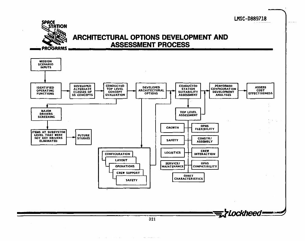
LMSC-D889718 SPACE
• ARCHITECTURAL OPTIONS DEVELOPMENT AND __ PROGRAMS ______ A .. S .. S_ES ... S .. M ....... EN ... T ...... P.R ... O ... C .. E ... S .. S ________ _
MISSION SCENARIO
INPUTS
IDENTIFIED DEVELOPED CONDUCTED DEVELOPED CONDUCTED PERFORMED ASSESS OPERATING - ALTERNATE - TOP LEVEL f- ARCH ITECTURAL -~
STATION r-~
CONFIGURATION f- COST CLASSES OF CONCEPT SUITABILITY DEVELOPMENT
FUNCTIONS SS CONCEPTS EVALUATION OPTIONS ASSESSMENT ANALYSES EFFECTIVENESS
I t
MAJOR TOP LEVEL DRIVERS ASSESSMENT r-
SCREENING
! I GROWTH ~ rl OPNS J ITEMS AT SUBSYSTEM FLEXI,BILITY
LEVEL THAT WERE FUTURE NOT KEY DRIVERS - STUDIES I ~ H CONSTRI I ELIMINATED SAFETY ASSEMBLY
CONFIGURATION I, I LOGISTICS ~ ~ CREW I INTERACTION
LAYOUT
I - I SERVICEI :~ H OPNS I OPERATIONS MAINTENANCE COMPATIBILITY
CREW SUPPORT I r ORBIT SAFETY I CHARACTERISTICS

LMSC-D8897l8
STATION OPERATIONS INFRASTRUCTURE
As. the study evolved, it became more clear that the overall station operations infrastructure required early definition as a means of assuring that the functional needs would be identified and could then be amplified. The facing page illustrates in simplified form the basic station infrastructure as invisioned at this time. Of importance to note is the continuing operational interaction with the ground and space communications asset. Integral to this infrastructure are the National Security operations, however, that aspect is not covered herein and will be presented in an accompanying classified volume.
Two operational factors which, to date~ have received less than adequate attention are the areas of rescue and emergency support, and space logistics (more aptly referred to as the integrated space logistics system). These two areas form an important part of the overall architectural definition and, as importantly, significantly influence the costing efforts. Accordingly, added effort was given to these areas to assure overall inclusion in the study.

SPACE LMSC-D889718
~ ~ STATION OPERATIONS INFRASTRUCTURE ... PROGRAMS .. ________________________________________________________ ....
STATION ASSEMBLY
& ACTIVATION
I RESCUE &
EMERGENCY SUPPORT
---..I
~
~
SPACE COMMUNICATIONS IIF
COMM & DATA I SYS OPS FLIGHT OPS SUPPORT
I I MISSION SUPPORT
I STA BASED XPORT SYS STATION r----OPERATIONS
I STAGE ASSY & CIO
+ I SERVICING/tv1AINT.
SPACE .., CONSTRUCT. & ASSY
LOGISTICS
I ORBITER SUPPORT
LCS!~TION B~I!:DUP
GROUND SYSTEM IIF & OPERATIONS
I I I STATION &
CAPABILITY
I EVOLUTION
J4- :-
J
I-I I

LMSC-D889718
OPERATIONS INFRASTRUCTURE (TYPICAL)
During the early identification and definition of station operations, two major categories of operational support evolved. These categories are:
1. Nominal & non-nominal indigenious station operations
2. Nominal & non-nominal station support fuctions
The basic station operations are listed in the facing page and are indicative of the top-tier operations only, as considerable more detail was fleshed-out in subsequent analysis. These sub-categories served, then, as the catalyst for more detailed effort relative to operations definition and identification conducted in support of the architectural configuration design and layout activities.
324

LMSC-D889718 -- - ------- - -SPACE
~ ~ OPERATIONS INFRASTRUCTURE (TVPICAL) ___ PROGRAMS __________________________________________________________ __
A. SPACE STATION OPERATIONS:
1. NOMINAL AND NON-NOMINAL STATION FUNCTIONS, e.g.:
• SYSTEM/SUBSYSTEMS OPS • CREW ROTATION/TRNG
• HOUSEKEEPING • FUEL/LIQUIDS MGMT
• LOGISTICS • DOCKING AND TRANSFER
• MAINTENANCE/REPAIR • ASSEMBLY /CONSTRUCTION
• DEGRADED SYS OPS • EMERGENCY /RESCUE OPS
, .
2. NOMINAL AND NON-NOMINAL STATION SUPPORT FUNCTIONS, e.g.:
• SPACECRAFT SERVICING • DEMONSTRATIONS
• STAGE BASING/ASSY & C/O • PROOF-OF-CONCEPT VALIDATIONS
• EXPER IMENT OPS • INDUSTRIAL MFG/MATERIALS PROCESSING
• BASIC RESEARCH • MILITARY APPLICATIONS
• TECHNOLOGY DEVELOPMENT • RESUPPLY /LOGISTICS
• FLUID XFER /MGMT • REMOTE OPS

...

LMSC-D889718
SPACE
• --- PROGRAMS iiiiiiiiiiiiiiiiiiiiiiiiiiiiiiiiiiiiiiiiiiiiiiiiiiiiiiiiiiiiiiiiiiiiiiiiiiiiiiiiiiiiiiiiiiiiiiiiiil
TASK 2-MISSION IMPLEMENTATION CONCEPTS
2.1 MISSION SCENARIO ANALYSIS AND ARCHITECTURAL CONCEPTS
2.2 ALTERNATIVE SYSTEMS CONCEPTS 2.3 MISSION OPERATIONS
ARCHITECTURAL DEVELOPMENT 2.4 ARCHITECTURAL ANALYSIS TRADES 2.5 EVOLUTION 2.6 CONFIGURATION 2.7 TECHNOLOGY DEVELOPMENT 2.8 CONCLUSIONS .
U) m n -f o Z N . I::
LMSC-D8897l8
ARCHITECTURAL IMPACT ANALYSIS
Upon completion of the mission scenario development effort, activity was initiated on the identification of the operations and associated functions relative to the basic missin study elements which were:
• • • Science Applications Commercial
• • • US National Security Space Operations (Technology Demonstration - A newly created category)
The methodology for this activity is presented in the chart on the facing page. As indicated, 23 basic operational function categories were identified and within this composite, over 280 subcategory architectural influencing factors were derived. Each factor was then examined and rated on a low, medium, and high basis. Examination of the multitude of ratings revealed that those factors exhibiting a medium to high rating score should be considered architectural impacts. Accordingly, 104 factors, approximately 40%, were th~~-'ln~orporated into other design criteria and used as a basis for subsequent design and layout of the candidate station configurations.

LMSC-D889718 SPACE
• ARCHITECTURAL IMPACT ANALYSIS ___ PROGRAMS .. ______________________________________________________ ___
A. 23 OPERATIONAL FUNCTIONS CATEGORIES IDENTIFIED
B. OVER 280 SUB-CATEGORY ARCHITECTURAL INFLUENCES FACTORS DELINEATED
C. EACH FACTOR ASSESSED ON A RANGE BASIS OF IMPACT (LOW TO HIGH)
ASSESSMENT SUB-CATEGORY CATEGORY --. IMPACT FACTORS
~ SUB-CATEGORY
DEVELOPMENT IDENTIFICATION RATING (23) ( >280)
, I
FED INTO CONFIG 1 r-- CONCEPT ANALYSES ..
& LIO DEV.
CANDIDATE ~ PRIORITI ZATION
INPUT RESULTS INTO, I- MAJOR ARCH. DRIVER .
SUMMARY
D. 104 FACTORS (40%) WERE IDENTIFIED WHICH WERE RATED AS HAVING SIGNIFICANT ARCHITECTURAL IMPACT
...

LMSC-D889718
CONFIGURATION CONCEPTS EVALUATION
The facing page presents the re~u1ts of evaluation of 11 of the 32 space station configuration developed in this study. Results for the evaluation of the other 21 configurations are given in Attachment 2 to this report.
Each of the 32 concept configurations were subjected to a KTA evaluation to determine overall practicality, mission suitability, and utility. The evaluation criteria used was as follows:
1.
2.
Orbiter Considerations 3. I No. of Orbiter launches I Config. fits cargo bay vol. I Adaptable to Orbiter support
Feasibility I Structural stability I Technical dev. practicality 4. I Ease of on-orbit assembly
F1exibil ity • Permits large struct. assy. • Multiple docking ports & access • .Adaptabi 1 i ty to growth • Permits artificial g • Meets mission/operations n~eds
Programmatics • Permits existing hdwr. application • Cost sensitive & cost practical
5. Performance Capability • Meets mission needs • Allow 0 to partial g
Each concept was individually rated one against the other based on the above criteria. Scores were then summed ·for each configuration concept and the concepts rank ordered. Results of this evaluation are presented in the Architectural Concept Configuration Evaluation Summary chart following these charts.
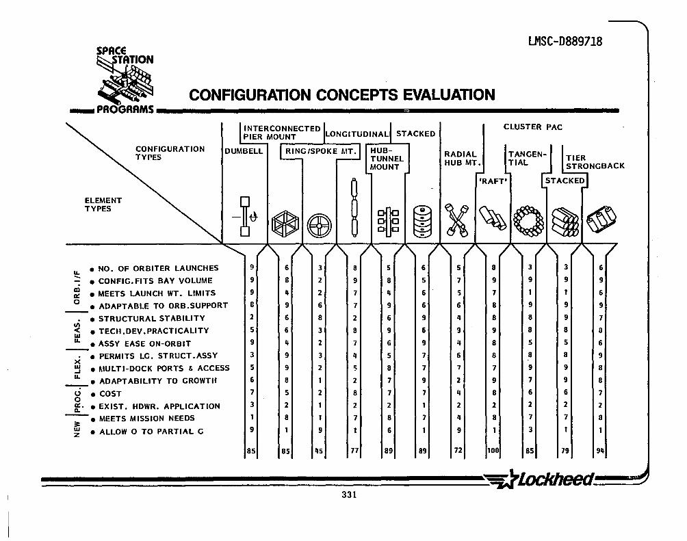
LMSC-D889718 SPACE
CONFIGURATION CONCEPTS EVALUATION • ... PROGRAMS .. ________________________________________________________ ___
CLUSTER PAC I INTERCONNECTED !. I PIER MOUNT \LONGITUDINAL\ STACKED
CONFIGURATION TYPES
DUMBELL I RING/SPOKE---,:rr.l HUB-L:.:..:.:. ,..:.::..:..:.J TUNNEL
ELEMENT TYPES
II. • NO. OF ORBITER LAUNCHES
- • CONFIG.FITS BAY VOLUME
~ • MEETS LAUNCH WT. LIMITS o
• ADAPTABLE TO ORB.SUPPORT
• STRUCTURAL STABILITY III ~ • TECU.DEV.PRACTICALITY
II. • ASSY EASE ON-ORBIT -• PERMITS LG. STRUCT .ASSY x
~ • MULTI-DOCK PORTS & ACCESS
II. • ADAPTABILITY TO GROWTH
o • COST o 8:' • EXIST. HDWR. APPLICATION
~ • MEETS MISSION NEEDS
~ • ALLOW 0 TO PARTIAL G
9
9
9
II
2
5
9
3
5
6
7
3
1
9
85
/\ 6
8
II
9
6
6
" 9
9
8
5
2
8
1
85
/ 3
2
2
6
8
3
2
3
2
1
2
1
1
9
45
/"
I
8
9
7
7
2
8
7
4
5
2
8
2
7
1
77
331
MOUNT
5
8
II
9
6
9
6
5
8
7
7
2
8
6
89
/\ 6
5
6
6
9
6
9
7
7
9
7
1
7
1
89
RADIAL HUB MT.
r'RAFT'
TANGENTIAL
TIER STRONGBACK
STACKED
/" /" 1,\ / 5
7
5
6
4
9
" 6
7
2
4
2
4
9
72
8
9
7
8
8
9
8
8
7
9
8
2
8
1
100
3
9
1
9
8
8
5
8
9
7
6
2
7
3
85
3
9
1
9
9
8
5
8
9
9
6
2
7
1
79
6
9
6
9
7
o 6
9
8
8
7
2
o 1
911

LMSC-D8897l8
FUNCTIONAL NEEDS TRANSLATED INTO ARCHITECTURAL DRIVERS
Upon completion of the development of the basic scenarios, a number of station influencing impact factors were identified. This effort resulted in the identification of some 23 categories within which numerous sub-category impact drivers were listed. The opposite page illustrates these categories within which numerous sub-category items were examined. Each of the items was then evaluated and where possible quantitatve numbers/values, etc;, developed for each. This permitted the analyst to then 'determine ' the overall impact on the station through the use of a rating score (low-medium-high). The results of this analysis were then promulgated to the architectural design team and used as a basis for preparation of basic input criteria and guidelines.
The evaluation results and summary of this effort are presented in subsequent pages herein. The activity was also closely keyed to the configuration concept analysis and assessment effort, and provided the backbone of design inputs used in the architectural definition effort.
332

SPACE LMSC-D889718
Ii . FUNCTIONAL NEEDS TRANSLATED INTO _PROGRAMS _____ A_R_C_H_I_T_E_CT_U_R_A_L_D_R_IV_E .. R_S ________ _
ENVIRONMENT
® SHUTTLE MANIFESTING
9 '.. LOGISTICS
@ POINTING & CONTROL
@ I1-i\ APP IDEPART ENVELOPES
® ® STATION ASSY 5 tr.\ MODULARrry
\UI HABITATS ®@2"" ~E~NC~LIIIIIO!ll!!S~E~D"""!V~E!'!!S~S~EL~-""'"
h:\ OPEN PLATFORM \l!I APPENDAGES
@ ~ MECH. PROVISIONS ~ CREW
OVER 280 INDIVIDUAL POTENTIAL STATION IMPACT
INFLUENCERS EXAMINED
@ COMM IIF @ ~p.;.;.;.;M~I~SS~· I~O~N""""!H"!"!!D!"!'W~R~S~UP~PO~R~T~·
---------------.., ~ ~ SUPPORT ELEMENTS A. INFLUENCE IMPACT CHARACTERIZED ~
FOR EACH CATEGORY ELEMENT
B. EACH IMPACT INFLUENCE RATED
• HIGH
• LOW
• MEDIUM
C. LOW ITEMS SCREENED OUT
D. HIGH IMED IMPACTS PRIORITI ZED
333

FUNCTIONAL NEEDS & ARCHITECTURAL DRIVERS - EXAMPLE VULNERABILITY/HAZARDS
LMSC-D8897l8
An example on the facing page of one of the 23 categories of functional impact on the station architecture is portrayed. The example illustrates the potential hazards and vulnerabilities of the station relative to the specific sub-listing within this category, each area (sub-listing) was examined relative to the potential influence on the station and a qualitative judgement made as to the extent of that influence, e.g., high, medium or low.
This page (opposite) represents the level of effort expended for each of the aforementioned 23 categories. The complete list is provided in an Attachment 2 to this document.
334

LMCS-D889718 SPACE
• _PROGRAMS _____ V_U_L_N_E_R_A_B_IL_IT_y.'_H_AZA __ R_D_S ________ _
RATING AREAS INFLUENCES (HML)
• MICRO-METEORITE ADDED 'SHIELDING'-DOUBLE BUMPER "'0.02 & 0.01 AL (EXAMPLE) L+
• SOLAR FLARE AVER.LESS THAN 20% OF PRIMARY RAD DOSE;MAX FLARE(1956) REQUIRES 500 G/CM2
"M-
• DEBRIS SCANING RADAR;BUMPER PROTECTION;MULTI-PURPOSE SCAVAGING VEH. M-
." DOCK ING OVERLOAD MAX IMPACT ",o.2 FT/SEC;HABITAT 'CLOSE-OUT';ADDED DOCK SYS. M-SAFETY FACTOR
• COLLISION CRIT .OF DOCK PORT LOCATION;EMERG.CREW RETREAT ;S/C-SHUTTLE M+ OPS APPROACH CONSTR.
• PRESSURE LOSS EMER.CREW RETREAT;"'0.90 NO PUNCTURE PROB.;EMERGENCY M+ RESCUE REQT.
• REMOTE HANDLINC DAMAGE RMS/CRANE MAX REACH(50'-100'); ORBITER RMS(50' ) ;TELEOP WITH ARMS "'101 M-
• PLUME IMPINGEMENT ORBITER "'10-2 TO 10-5 DIRECT PRCS PRESSURE;EJECTA ENVELOPE M+ ORB/OTV /TMS
• SUN SHADOWING DOCKING PORT(S) LOCATION;RADIATOR POSITION;RESULT IN S.A.SHADOW H-
• POWER LOSS SAFETY CRITICAL;BACK-UP SYSTEM;POSSIBLE CREW RESCUE/EARTH M+ RETURN
• THERMAL IMBALANCE THERMAL OVERLOAD = REDUCED FUNCTIONS (SUPPORT); M ADDED EQUIP/RADIATORS
• CONTMlINATION DOCKING PORT(S) LOCATION;APPROACH/DEPART ENVELOPES;PLUME EJECTA M+
• RADIATION LEO (QUARTERLY): BONE MARROW SCM DEPTH - 35REM;SKIN 0.1 MM DEPTH = 105 REM; LENS 3MM DEPTH = 52 REM; TESTES 3CM DEPTH = 18 REM. 60° ORBIT "'20 TO 23 REM/2q HRS;900 MORE SEVERE SHIELDING RANGE: 281° "'0.1 G/CM2 & 60° "'0.3 G/CM2 M


SPACE LMSC-D889718
CONFIGURATION CONCEPTS •• ... PROGRAMS __________________________________________________________ ...
ET'S DUMBBELL
ACC'S
ACC'S
ET COMBO
RADIAL -HUB MT.
X ACC'S
LONGITUDINAL
STACKED ET'S . ACC'S COMBO
COMBO CYL. RING/SPOKE MT.
RAFTED-PLATFORM
BEADS
LMSC-D889718
SPACECRAFT HABITABILITY VOL. COMPARISON
A number of spacecraft were examined relative to available cubic volume per crew member. The opposite page indicates the available volume for some 8 spacecraft/stations orbited to date. The chart also indicates the number of flight crew persons, maximum orbital time, and the pressurized .vo1ume per spacecraft. Obviously, the numbers provided do not take into account (for all cases) the amount of equipment volume which must be subtracted from the total available volume. Consequently, certain available volumes may appear to be extremely large in comparison to the early spacecraft. No attempt was made to determine 'lost volume' for any of the spacecraft. As shown in the previous page, the CPM available habitability volume falls above the minimum tolerance limit.
As a result of the studies consulted, actual spacecraft flight hardware values, and current NASA habitability criteria, a value of not less than 275 cu. ft. of free volume per crew person has been assumed as baseline for this study. Accordingly, this value (275 cu. ft.) has been utilized as the criteria for and during the architectural design phase.
338

LMSC-D889718 SPACE
:Ii _ PROGRAMS SPACECRAFT HABITABIUTV VOL COMPARISON
SPACECRAFT
MERCURY
GEMINI
APOLLO
SOYUZ*
SKYLAB
SALYUT
ORBITER
SPACELAB
I&II &II U.
U
S SA
500r-----r---------+-------------~
ACCEPTABLE PERFORMANCE LIMIT
100 150 200 250 300 350 qOO
PRESSURIZED VOL (CU.FT.) MAX ORBITAL TIME (DAY /HR/M)
54 1-10-20
88 13-18-35
210 12-13-51
36q 17-16-59
9,550 (USEFUL) Oq,...1-15
3178 211-x-x
2331 28-x-x(POSTULATED)
25'13 27-x-x(POSTULATED)
MERCURY = ® GEMINI = @ APOLLO = 0 SOYUZ = ® SKY LAB = @ SALYUT = @ ORBITER = ® SPACELAB = ®
NO. OF FLT .CREW CU. FT. VOL/CREWMAN
1 5'1
2 'Iq
3 70" 2 182**
3 3183** 2(+3 FOR 7 DAYS) 1589**
q 583**
II+x 636**
·ORBITAL COMPT. & RE-ENTRY MODULE (13'1.2 CU.FT.) "INTERIOR EQUIP & 'LOST VOL'NOT INCLUDED
339

LMSC-D889718
CPM - CONCEPT A - 1
This configuration is identical in basic arrangement to Concept A although several changes are to be noted as illustrated on the facing page. The 1ivinQ module has been designed toaccommadate up to 16 crew persons, and its length was limited since both the living sub-module and CZ sub-module are planned for instaliation within the external tank, therefore, certain functions had to be transferred into the C2 sub-module. Specifically, exercise/physical fitness and associated stowage lockers were positioned in the aft dome end of the sub-module. Also located in this area is a Ibio-medica1 1
panel which can be used in conjunction with the exercise regimes.
At the opposite end, a mini-health care/maintenance sub-compartment has been located. This area serves a dual purpose through provision for a commanders conference area when the dispensary type functions are not being conducted. Since there will be limited EVA, no laboratory functions, and reduced typical external station missions (free flyers, tethered platforms, etc.) support, a mini-health care and dispensary capability was considered adequate. These capabilities (dispensary and exercise area) have also been incorporated in further concepts presented in this sequence (Concepts B through E).
340

SPACE LMSC-D889718
:$I _ PROGRAMS -:=:-__ .;C;.P.:.:M:.-~C~O:::.:.:NC:::;EP~T.:..:A~-1:.... ________ _
CONFERENCE PHYSICAL FITNESS MONITORING SYSTEMS TABLE
LITTER CHAIR
~IP" SYSTEMS MODULE C2 CONSOLE CONTROL MODULE
NOISE BARRIER PARTITION
- EMERGENCY TREATMENT - MEDICAL EXAM.
WASTE MANAGEMENT
LOCKERS
GYM FUNCTIONS SECTION A A AREA ----I
I \! I
oj' ~~~;g
FITNESS EQUIP TYPICAL
OVERHEAD STORAGE
PHYSICAL FITNESS MONITORING SYSTEMS
DUCTING
~~!;;;:;;;:::;;:J;J;~~'f/-~ DUCT CABLING
~ ... , rlON ·0 - R

LMSC-D889718
PARTIAL GRAVITY STATION EXAMPLES - SCHEMATIC
The opposing page presents three selected rotation space station schematic representations~ -:Each rotate about a central hub, thereby providing partial gravity at the extremeties, e.g., outer habitat/lab or ring segment. Numerous studies indicate that the radius fro~~th~ rotational hub must be. at a minimum. at least 100 ft. and preferably 200 ft. for a gravity of over 0.5 g's and a rotation rate of about 4 rpm in order not to increase the crew persons' weight 1n excess of 15 to 20% dtie to the Coriolis and ve16c1ty l toward-rotation effects. Thus, as can be seen in the facing figures, significant impact on the station architecture is encountered in order to provide the necessary distance from the rotational hub. This constraint and others are further elaborated upon .in the next pages. .

SPACE LMSC-D889718
~ PARTIAL GRAVITY STATION EXAM PLES---" SCHEMATICS ~ (SELECTED EXAMPLES) ... PROGRAMS ________________________________________________________ ___
DUMB-BELL CONCEPT
ROTATION
0+-+
TOP VIEW
ROTATION
HABITAT
SER. MODULE
* NON-TETHERED CONCEPTS
HUB & DUMBELL CONCEPT
END VIEW
LOG. MODULE
HABITAT
CAROUSEL CONCEPT
LAB
TOP VIEW
343
LMSC-D8897l8
TETHER IMPLICATIONS & ARTIFICIAL GRAVITY
The following two charts indicate the nature of the utilization of 'tethered' spacecraft and/or elements to the station. Initial utilization of the tether was with the Gemini 6/7 Mission wherein the spacecraft was tethered to the Agena vehicle. Since'that time, numerous studies have been made relative to the use of tethers for advanced space programs. Two recent study contracts have resulted in the selection of a U.S. aerospace contractor working in concert with a European contractor to develop a tethered satellite 'suspended' from the orbiter. The next two pages briefly outline the advantages of the tethered station-spacecraft, applications of artificial G in the station, and general applications of artificial G for various tethered elements. Results of this analysis have been provided for the basic station configuration layout studies associated with tethered elements.
Of particular interest to this study were three aspects of the early analysis of tethers and are (1) Ability to 'reel in/out' pallets/platforms to support the station; (2) Possible power availability; and (3) Tether 'release energy' for 'launch or reentry' trajectories. Nonetheless, .it is felt that additional study be applied before more substantial ·application of the tether principals be incorporated into the evolution of the station architectural framework.

LMSC-D889718
~ ~ TETHER IMPLICATIONS & ARTIFICIAL GRAVITY. ___ PR~AMS ____________________________________________ __
A. TETHERING SPACECRAFT WAS INITIALLY ATTEMPTED ON GEMINI 6/7 MISSION B. LEVEL OF G (GRAVITY) OBTAINABLE IS PROPORTIONAL TO LENGTH OF·TETHER
FROM CENTER OF SYSTEM MASS & EQUALS 4 x 10⁻⁴ G/KM IN LOW EARTH ORBIT
C; ADVANTAGE: 1. FREE OF THE LARGE 'FLOOR TO CEILING' G VARIATIONS AND 2. DEBILITATING/UNPLEASANT CORIOLIS EFFECTS 3. TWO AXIS STABILIZATION
D. G-LEVEL ATTAINABLE: 1. TETHER BECOMES SIGNIFICANT PART 'OF STATION MASS TO ACHIEVE 0.1 G . 2. TETHER MASS IS RELATIVELY MINOR FOR 0.0'5 G's OR LESS "'.:.
I , .;., ~ '.
E. APPLICATIONS AT 0.01 TO 0.1 G IN A STATIPN: 1. SIMPLIFICATION OF CERTAIN CREW AIDS/ACOUTREMENTS (IVA) 2. FACILITATE LIQUID'S FLOW (SHOWER/TOILET) - (IVA) 3. MINIMIZATION OF SMALL LOOSE FLOATING OBJECTS (IVA) 4. ENHANCEMENT OF TOOL USE VIA TETHER ELIMINATION (IVA) 5. VARIABLE G FOR PHYSICS/LIFE SCIENCE/COMMERCIAL RESEARCH

..

LMSC-D889718
TASK 2-MISSION IMPLEMENTATION CONCEPTS
2.1 MISSION SCENARIO ANALYSIS AND ARCHITECTURAL CONCEPTS
2.2 ALTERNATIVE SYSTEMS CONCEPTS 2.3 MISSION OPERATIONS
ARCHITECTURAL DEVELOPMENT 2.4 ARCHITECTURAL ANALYSIS TRADES 2.5 EVOLUTION 2.6 CONFIGURATION 2.7 TECHNOLOGY DEVELOPMENT 2.8 CONCLUSIONS U)
m n -I o Z N . VI

LMSC-D8897l8
RATIONALE FOR STATION EVOLUTION
Complete and fully justified station evolution rationale is beyond the scope, and current state of mission/user need definition at this time. Nonetheless, several important and pivotal issues can be identified which bear upon the evolution consideration. Presently, six basic categories have been defined wherein the rationale has been allocated and are:
• • • Programatics Expand Capabilities Operational Enhancement
• • • User Needs Research & Development Demonstrations/Technology
Nearly 60 discrete rational items have been identified and many have sub-factors which further expand the list. The following pages. address the currently envisioned rationale per each category. They are, in general, self explanatory and need little further amplification as to meaning. Subsequent future studies could logically be addressed as to the substantive impact of each and the associated relative merit. Of all the rationale presented, that category associated with the sub-category (under Programmatics) entitled 'Intangables ' proves to be the most difficult to deal with in terms of methods of substantiation, dollar or instrinsic value, benefit, and importance. Certainly, NASA budget forecasts are difficult to portray at this time, thus, the budgetary picture is also elusive.
The general composite of rationale for evolution were submitted to and applied in the generic studies of conceptual station architectural definition and 'build-up'. As the concepts were narrowed, the rationale became· more important, particularly as to the evolutionary stepped build-up sequence and the associated costing implications.
348

--, '
SPACE I11SC-D889718
• _ PROGRAMS ___ R_/i._~_IO_N_A_L_E_F_O_R_S_T/i._~_I_O_N_E_V_O_L_U_T_IO_N ______ _
PROGRAMMATICS
I. PLANNED & ORCHESTRATED STAGED BUDGETARY ALLOCATIONS 2. POSSIBLE FINANCIAL PARTICIPATION BY FOREIGN NATIONALS 3. ENABLE GREATER SENSITIVITY TO FUTURE OUT-YEAR FUNDING PLANNING 4. PRECLUDE MUTUALLY EXCLUSIVE DEAD-END DEVELOPMENT EFFORTS 5. .GREATER UTILIZATION OF STS RESIDUALS (E.G.~ EXTERNAL TANK) 6. PROVIDE FOR AND/OR ENHANCE INTANGIBLES
NATIONAL PRESTIGE NATIONAL SECURITY TECHNOLOGY TRANSFER SUPPORT TO FOREIGN POLICY SUPPORT TO PRIVATE/EDUCATION SECTOR
349


SPACE LMSC-D889718
• _PROGRRM5 ___ R_"_~_IO_N_A_L_E_F_O_R_S~_'fi._~_O_N_EV_O_L_UTl_O_N ______ _
I. ADDED SCOPE OF R&D ACTIVITIES INCREASED NUMBER
R&D
INCREASED CAPABILITY (WT/PWR/VOL) ADDED SUPPORT PERSONNEL & FULL SHIFT OPS ADDED ON-ORBIT TIME INCREMENTS (EQUIP. TIE-UP) EXPANDED SUPPORT NEEDS INCREASED LOGISTICS POTENTIAL REMOTE OPS
2. INCREASED STRUCTURE AND HDWR TO ~ACILITATE ARTIFICIAL GRAVITY 3. ADDED CAPABILITY TO EXAMINE LONG-TERM EFFECTS ON BIOLOGICAL/
PLANT/ANIMAL SPECIMENS NON-HUMAN MODELS RESEARCH ON IN-FLT GROWN SUSTENANCE CONTINUED-DIRECT P.I. INTERACTION SERENDIPITY INTERACTION .
4. EVALUATION OF LONG-TERM CREW RESIDENCY
:lfi 1

LMSC-D889718
OPTIONS IN STATION SUPPORT/DEVELOPMENT
The station growth and evolution sequence has been defined in a series of 12 discrete steps (discussed in subsequent pages) •. A myriad of alternative support and development options are currently being addressed, however, a selected few are presented on the facing page to illustrate their significance. Although this study used the Orbiter as the primary launch .vehic1e, options such as the Ariane and Heavy Launch Vehicle (or similar vehicles) have been suggested as potential station support elements. Avai1~bi1ity of the HLV is problematical whereas the Ariane is an existing program with solid plans for uprating, thus, possible future consideration of the Ariane as an unmanned launch vehicle for station sub-elements and/or logistics may be worthy of examination particularly if European participation is desired.
The need for an orbital transport vehicle is highly viable, however, the RDT&E date for station-app1ication- support has not been formally established (e.g., 1990 to 1993 time frame). Similarly, the numbers, types, and capabilities of the free flyers anticipated for the 1990 t~ 2000 time frame are somewhat soft at this time, however, every indication tends to support ~he potential of their availability beginning late 1991 and continuing thereafter. The potential application of certain of these free flyers to more simplified payloads exists relative ,to the possib1ility of tethering these from the station itself. .
A second (or 3rd) station p~tentia1-exists and could be implemented as early as 1994/5. In association with'the station(s) will be the need for a rescue vehicle (with mu1ti-purpose,app1ications) which could come on line in the mid-1990's. A nuclear power source may be required for the Command Post Module (000 mission/program), thus, it may launched as early as 1995., This power source may also have application to station tethered Oses for supplemental power. .
352

z o -I-;:) ..I
~ ~~ z o -~ .~
en z -en z o -t: o

--------------------------------------------~--------~--------------------------
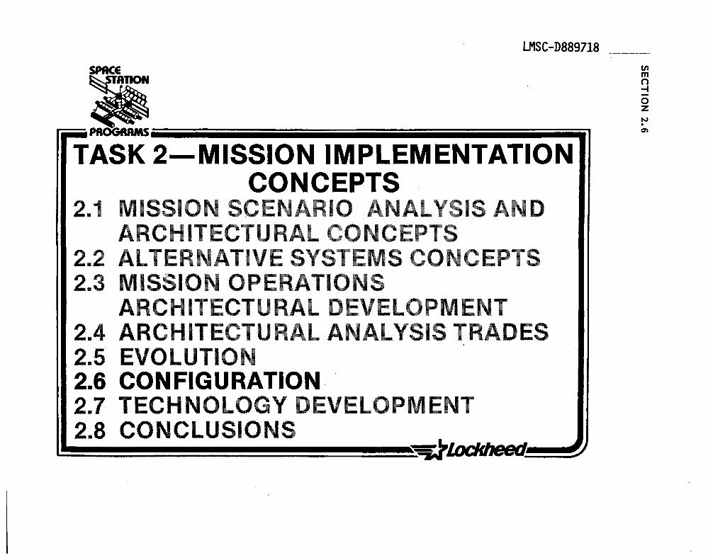
LMSC-D889718
TASK 2-MISSION IMPLEMENTATION CONCEPTS
2.1 MISSION SCENARIO ANALYSIS AND ARCHITECTURAL CONCEPTS
2.2 ALTERNATIVE SYSTEMS CONCEPTS 2.3 MISSION OPERATiONS
ARCHITECTURAL DEVELOPMENT 2.4 ARCHITECTURAL ANALYSIS TRADES 2.5 EVOLUTION 2.6 CONFIGURATION 2.7 TECHNOLOGY DEVELOPMENT 2.8 CONCLUSIONS ~~~~~~~~~~~~~~~
(J) m n -I o Z N . en
LMSC-D889718
SPACE STATION ARCHITECTURE - CONFIGURATION
The five major configuration alternatives for the space station are symbolized on this chart and discussed in this section.
The principal system design drivers for all of these configurations are listed below:
• CONTROL, STABILITY, POINTING • ORIENTATION; EARTH FIXED/INERTIAL/COMBINATIONS • SAFETY • CREW SIZE • DOCKING CAPABILITY • PAYLOAD ACCOMODATION AND FOV • ANTENNAE FOV. • MASS PROPERTIES, M OF I + CG EXCURSIONS • POWER SUPPLY TYPE + ORIENTATION • RCS PLUME INPINGEMENT/CONTAMINATION • OTY + VISITING SPACECRAFT OPERATIONS • SERVICING • MODULARITY, EVOLUTIONARY • THERMAL CONTROL • LAUNCH CONFIGURATION • EVA
The shuttle is always used as the basic transportation verhic1e with a capability of 63,000 1bs to 150 NM orbit at 28.5° inclination, this is conservative as some projections suggest that by 1985,'with all SRB, ET + shuttle improvements included, the capability could be as high as 80,000 1bs.
The probability of funding being avai1ab1~ for.~he heavy lift shu~t1e configurations is considered low at this time. Therefore, heavy lift launch vehicles are not considered in this study.
In addition to the command post concept the military space station could be developed in the same way as the LMSC reference station; or it could be a series of free flyers operating around a.basic core command system. These are numerous possibilities.
~~~~~~~~~~~~~~~~~~~~ 356

LMSC-D889718
SPACE STATION ARCHITECTURE
INTEGRAL DETACHED
ATTACHED
MOUNTED TETHERED

LMSC-D889718
REFERENCE SPACE STATION - ISOMETRIC
The reference configuration is shown here with representative visiting spacecraft, and EVA astronaut, manned maneuvering unit and two teleoperating maneuvering uni~s.
In the upper right corner is a General Dynamics space based (and assembled) cryogenic OTV concept; a wide body Centaur is stationed close by the OTV shelter and refuelling pier, (surrogate shuttle).
To the lower right can be seen an AXAF spacecraft and a typical logistics module along with a manned TMS concept.

00 r-t ....... en 00 00 &:::I
I U en 3
o -a: ~ :E o en -z o ~ ~ w o ~ en w o z w a: w u. w a:
o .. ~ - a:: •
'" ... a:: ",a:: C!)
v'" 0 f a:: '" Q.
I

LMSC-D8897l8
REFERENCE SPACE STATION BUILD UP
The attached sketches depict the evolutionary build up, through seven distinct phases, from a small 3 man/single module station to a 6 man all-embracing configuration. The build-up is arranged such that the evolution could be stopped at any ph~se and a useful facility remain operational. Twelve launches are required to place the facility on station not including approximately two resupply launches per year.
360
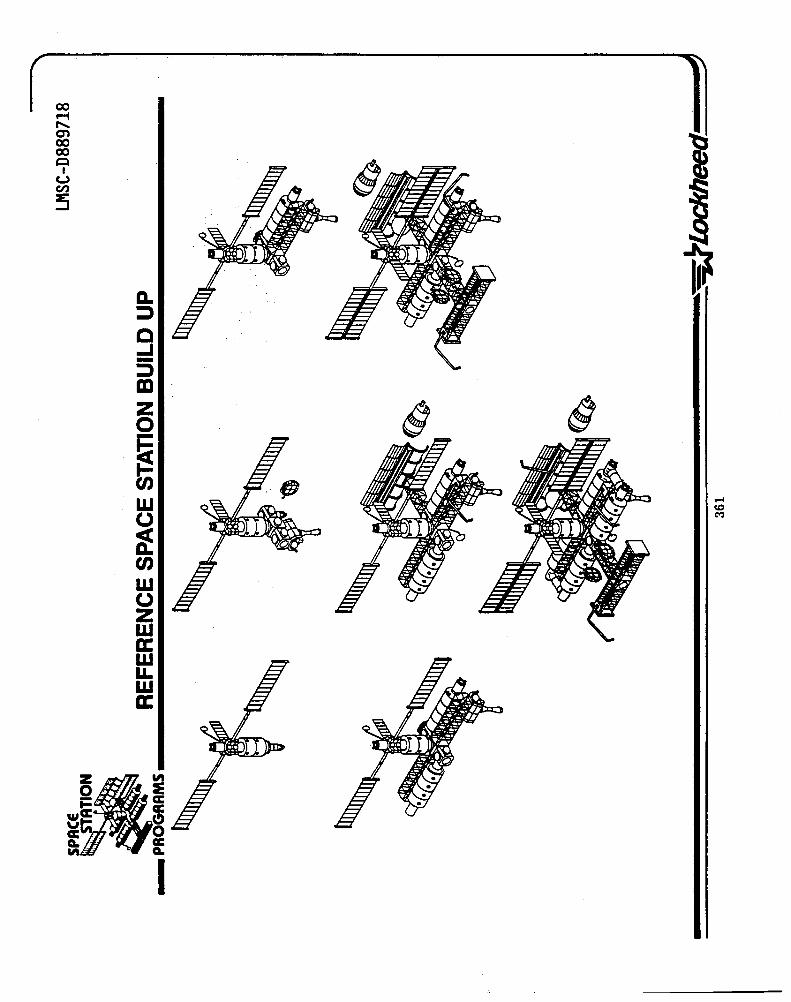
co .-t ,....., en co co ~
I U CI)
~
D. ~ :l C ...J -:l lEI Z 0 -tee t; w -' co 0 C"')
~ UJ W 0 Z w a: w LL W a:

LMSC-D8897l8
REFERENCE STATION LAUNCH CONFIGURATIONS
The shuttle payload bay is fully occupied for almost all twelve build-up launches as can be seen from this drawing, however, although the available volume is effectively used, the total weight capability is not as can be seen on the preceding chart. This excess' capability could be used, of course, for experiments, consumables, contingency etc.
362

tn Z o ~ a: :)
CJ EL: z o u :c o z :)
:3 I
z o ~ ~ w o ~ tn W o z w a: w I.L w a:

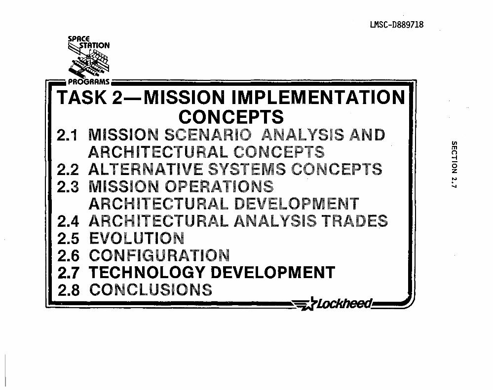
LMSC-D889718 SPACE
• r-=.. PROGRAMS iiiiiiiiiiiiiiiiiiiiiiiiiiiiiiiiiiiiiiiiiiiiiiiiiiiiiiiiiiiiiiiiiiiiiiiiiiiiiiiiiiiiiiiiiiiiiiiiiiiiiiiiiiiiiiiiiiiiiiil
TASK 2-MISSION IMPLEMENTATION CONCEPTS
2.1 MISSION SCENARIO ANALYSIS AN D ARCHITECTURAL CONCEPTS
2.2 ALTERNATIVE SYSTEMS CO CEPTS 2.3 MISSION OPERATIONS
ARCH ITECTU RAL DEVELOPM ENT 2.4 ARCHITECTURAL ANALYSIS TRADES 2.5 EVOLUTION 2.6 CONFIGURATION 2.7 TECHNOLOGY DEVELOPMENT 2.8 CONCLUSIONS
tn m n -t o Z N . ...,

LMSC-D889718
TECHNOLOGY DEVELOPMENT APPROACH
In the course of defining and identifying technologies that need to be developed further to support the feasibility of a Space Station, LMSC identified technology issues, TOMs, and technologies needing development.
The TOMs selected need to have a mix of analysis and trade-offs with an emphasis on key subsystem technologies that are drivers in the total syst~m'selected technologies must be congruent with the need to develop capabilities for an\evolutionary Space Station _ growth in habitats, larger structural assembly, propellant transfer, distributed data processing, etc.

LMSC-:-0889718 SPACE
• .. TECHNOLOGY DEVELOPMENT APPROACH ... PROGRAMS ________________________________________________ __
• TECHNOLOGY DEVELOPMENT ISSUES
• TECHNOLOGY DEVELOPMENT MISSIONS
• TECHNOLOGIES NEEDING DEVELOPMENT

'SPACE ..
TECHNOLOGY DEVELOPMENT ISSUES ELECTRICAL POWER SYSTEMS
lJ1SC-D889718
:Ii ... PROGRAMS __________________________________________________ _
IECHNOLOGY ISSUES ALIEBNAIIVE APPBOACHES SYSIEMlSUBSYSIEMlIMEACIS SOLAR ARRAY
LARGE ARRAY DYNAMICS SOLAR VS. NUCLEAR ELECT POWER
IMPROVED SOLAR CELL THIN. HIGH PERFORM CELLS STRUCTURES TECHNOLOGY
; CONCENTRATOR ARRAY ATTITUDE CONTROL SYSTEM POWER DISTRIBUTION AC VS. DC POWER POWER COND & DISTRIBUTION SYSTEM
HIGH VOLTAGE DISTRIB AC/DC DISTRIBUTION
MICROPROCESSOR CONTROL SYS THERMAL MANAGEMENT AUTOMATED POWER MGMT IMPROVED ARRAY STRUCTURE DATA MANAGEMENT
MULTI HUNDRED KW SYS. WELDED SOLAR CELL ORBITAL REPLACEMENT INTERCONNECT
REGENERATIVE FUEL CELLS OPER CONSTRAINTS TO S'_ ~VICE MODULARITY VEHICLE
NUCLEAR POWER MOMENTUM DEVICES REACTOR TECHNOLOGY ENVIRON INTERACTION -
HEAT REJECTION (POWER STORAGE) PLASMA/RADIATION NUCLEAR SHIELDING THERMAL/ELECT CONVERSION POWER PLATFORM

SPACE
• "_PROGRAMS ________________________ _
LMSC-D889718
TECHNOLOGY DEVELOPMENT MISSIONS (CONT)
SUBSYSTEM TECHNOLOGY DEVELOPMENT MISSION CRITICAL ~I~~F~OTENTIAL NEED DEMONSTRATE COMMAND/CONTROL FOR X PROXIMITY FLYERS
>.
ELECTRICAL POWER DEMONSTRATE DEPLOYMENT OF LARGE SOLAR ARRAYS
X
VERIFY LIGHTWEIGHT SOLAR ARRAY PERFORMANCE AND LIFE
X
SPACE DEMONSTRATION OF X CONCENTRATOR CELL SOLAR ARRAY DEMONSTRATE AUTOMATED POWER X
" MANAGEMENT IN SPACE HIGH VOLTAGE POWER TRANSFER X OVER LONG LINES
THERMAL DEMONSTRATE ASSEMBLY AND X MANAGEMENT PERFORMANCE OF LARGE DEPLOYED
RADIATORS VERIFY LIFE OF SYSTEM CONCENTRATED HEAT REJECTION/
X COATINGS/JOINTS

SPRCE····
TECHNOLOGIES THAT NEED DEVELOPMENT
LMSC-D889718
• ... PROGRAMS __________________________________________________ _
• LARGE SPACE STRUCTURE ASSEMBLY CONCEPTS
• PRECISION STRUCTURES ASSEMBLY IN SPACE
• METAL MATRIX FOR LARGE : STRUCTURES
• REMOTE MANIPULATOR I ROBOTICS APPLICATIONS
• CRYOGENIC STORAGEI TRANSFER/RELIQUIFICATION
..
• MONO/BIPROPELLANT TRANSFER
• PROPELLANT MANAGEMENT . DEVICES '. ( ORIENTATION)
• REHOTE-· PROPELLANT CONNECT/DISCONNECT
...
• ADVANCED PROPULSION MPD ION LOW THRUST CHEMICALS HIGH PERFORMANCE STORABLES
• ADAPTIVE CONTROL SYSTEM FOR LARGE, FLEXIBLE STRUCTURE
• AUTONOMOUS CONTROL FOR PROXIMITY FREE FLYERS
PLATFORMS OTV
• LARGE SOLAR ARRAYS DEPLOYMENT PERFORMANCE LIFE
. . MAINTENANCE SOLAR CELL IMPROVEMENTS
• NUCLEAR TECHNOLOGY' REACTOR SHIELDING THERMOELECTRIC CONVERSION HEAT REJECTION
1
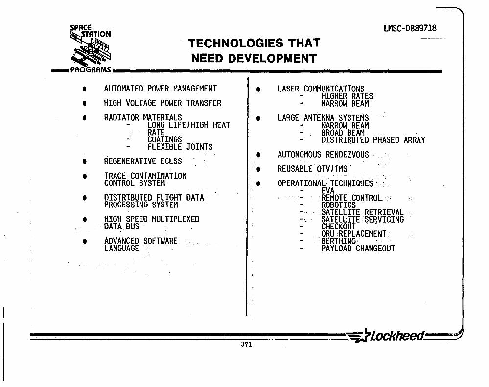
SPACE
TECHNOLOGIES THAT NEED DEVELOPMENT
LMSC-D889718
ali ___ PROGRAMS __________________________________________________ __
• AUTOMATED POWER MANAGEMENT • HIGH VOLTAGE POWER TRANSFER • RADIATOR MATERIALS
LONG LIFE/HIGH HEAT RATE COATINGS FLEXIBLE JOINTS
• REGENERATIVE ECLSS • TRACE CONTAMINATION
CONTROL SYSTEM • DISTRIBUTED FLIGHT DATA",:
PROCESSING SYSTEM • HIGH SPEED MULTIPLEXED
DATA BUS
• ADVANCED SOFTWARE LANGUAGE
•
•
• • .'
LASER COMMUNICATIONS HIGHER RATES NARROW BEAM
LARGE ANTENNA SYSTEMS NARROW BEAM BROAD BEAM . DISTRIBUTED. PHASED ARRAY
AUTONOMOUS RENDEZVOUS ' . REUSABLE OTV/TMS .
. . OPERATIONAL: TECHNIQUES,· " . . - EVA .. ..
. REMOTE CONTROL·:: ROBOTICS -
-. ~ .. ' SATELLITE ,RETRIEVAL -. SATELLITE SERVICING CHECKOUT . - ' ."
. ORU ,REPLACEMENT " BERTHING: . , PAYLOAD CHANGEOUT

--------------------------------~----~~------------------------------------

LMSC-D889718
Ii -- PROGRAMS iiiiiiiiiiiiiiiiiiiiiiiiiiiiiiiiiiiiiiiiiiiiiiiiiiiiiiiiiiiiiiiiiiiiiiiiiiiiiiiiiiiiiiiiiiiiiiiiiiiiiiiiiiiiiiiiiiiiiiiiiiiiiiiiiiiiiiiiil
TASK 2-MISSION IMPLEMENTATION CONCEPTS
2.1 MISSION SCENARIO ANALYSIS AND ARCHITECTURAL CONCEPTS
2.2 ALTERNATIVE SYSTEMS CONCEPTS 2.3 MISSION OPERATIONS
ARCHITECTURAL DEVELOPMENT 2.4 ARCHITECTURAL ANALYSIS TRADES 2.5 EVOLUTION 2.6 CONFIGURATION 2.7 TECHNOLOGY DEVELOPMENT 2.8 CONCLUSIONS Vl
m n -f o Z N . co

CONCLUSIONS TASK 2
LMSC-D889718 TASK 2 - 1T -
Our analysis of mission support requirements and development of station architectural concepts, system implementation concepts, configuration alternatives, and technology considerations leading to selection of a reference space station configuration and evolutionary plan, resulted in the conclusions shown on the facing page.
We feel that our reference configuration is a reasonable concept and in accordance with the depth to which we performed analyses of optional condidates represents the best selection.
We concluded that the station configuration is an ·open book· at this stage of inv.stigation and that more extensive subsystem performance requirements must be developed in order to provide the basis ultimately for a design selection.
A major conclusion we have reached is that the station should be designed and operated as a true ·space facility· resource that can satisfy the needs of multiple users and can also have the flexibility to meet unique user needs without interfering with the basic station capability. We conclude as a follow on to this that Logistics to support the station and the use of a ground based transportation system as well as station based transport vehicles will playa dominant role in the design and operation of the space station.

SPACE
CONCLUSIONS TASK 2
LMSC-D889718 TASK 2 - 1 -
• ___ PROGRAMS __________________________________________________ ___
• DERIVED STATION MAJOR FUNCTIONAL ATTRIBUTES ARE COMMON TO THE MAJORITY OF MISSIONS EVALUATED
• USER REQUIREMENTS CAN BE. MET BY APPLICATION OF BASIC INHERENT SPACE STATION CAPABILITIES PLUS MISSION UNIQUE SUPPORT EQUIPMENT AND PROCEDURES
• SPACE OPERATIONS CATEGORY MISSIONS ARE THE MAJOR DRIVER FOR SYSTEMS ARCHITECTURE
• THE STATION MUST RELY ON BOTH ATTACHED SUPPORT ELEMENTS AND FREE FLYER SATELLITES TO ACCOMODATE THE SPECTRUM OF MISSIONS EVALUATED
• 000 RESEARCH AND DEVELOPMENT MISSIONS CAN EFFECTIVELY USE CAPABILITY OF A SPACE STATION
• OPERATIONAL MISSIONS ARE BEST IMPLEMENTED BY DETACHED MISSION UNIQUE FREE FLYERS .
• USE OF TETHER CONCEPTS APPEARS FEASIBLE AND FURTHER STUDIES OF THIS APPLICATION ARE NEEDED
• THE STS MUST PLAY A DOMINANT ROLE IN SUPPORT OF THE SPACE ~TATION • EXTERNAL TANKS (ETS) ARE VIABLE HARDWARE CANDIDATES FOR MULTIPLE USES BY THE
STATION • STATION CONFIGURATION IS AN "OPEN' BOOK" AT THIS TIME - EXTENSIVE SUBSYSTEM
PERFORMANCE REQUIREMENTS NEED TO BE DEVELOPED • A REASONABLE EVOLUTIONARY GROWTH FROM AN INITIAL LOW CAPABILITY TO A FINAL
HIGH CAPABILITY SPACE STATION CAN BE ACHIEVED IN SIX YEARS


LMSC-D889718
• r=. PROGRAMS iiiiiiiiiiiiiiiiiiiiiiiiiiiiiiiiiiiiiiiiiiiiiiiiiiiiiiiiiiiiiiiiiiiiiiiiiiiiiiiiiiiiiiiiiiiiiiiiiiiiiiiiiiiiiiiiiiiiiiiiiiiiiiil
TASK 3 - COST AND PROGRAMMA TIC ANALYSIS
3. 1 BENEFITS 3.2 COST,SCHEDULE AND
FUNDING
en m n -I -o z CAl . ....

LMSC-D8897l8
THE LANGUAGE OF BENEFIT ASSESSMENT
Orderly discussion of Space Station benefits requires a common linguistic framework. A useful beginning is the definition of a benefit from Webster's New International Dictionary (Second Edition):
"Whatever promotes welfare; advantage; profit."
This definition suggest three convenient classifications for benefits. Each class benefits a different group and each is assessed in a different way. 'Welfare' benefits accrue to the populace at large, either nationally or internationally. They are factors that motivate decisions, yet are not us~d to justify these decisions analytically. This is because welfare benefits are the least tangible of all three classes and hence are difficult to quantify.
'Advantage' benefits accrue to the users of a system such as Space Station who have a job to be done and have alternative ways to do this job. The alternatives may be either of two types, i.e., 'equal capability' or 'unequal capability'. In the first case, the mission capability of alternatives (payload capability, data return, etc.) is approximately equal andlife cycle cost becomes the discriminator between approaches. In the unequal-capability case, the mission performance of alternative approaches is significantly different and cost is just one factor in selection of a preferred approach. For both of these advantage-type benefits, the techniques ~f cost-benefit analysis apply.
'Profit" type benefits, as defined here, accrue to a commercial firm. These are the competitive margins that c-an be realized with a new venture. They are quantified using profitability analysis, and such measures as return on investment and cash flow. Such benefits are not the focus of this analysis.
378

\
LMSC-D889718 SPACE
~ THE LANGUAGE OF BENEFIT ASSESSMENT ___ PR~AMS ________________________________________________ __
I WELFARE
• TO POPULACE. • NATIONAL SECURITY • NATIONAL PRESTIGE • TECHNO ECONOMIC
STABILITY • INT'L COOPERATION
BENEFIT ASSESSMENT (QUALITATIVE)
DEFINITION OF A BENEFIT: "WHATEVER PROMOTES WELFAREI
ADVANTAGE I PROFIT." I I
ADVANTAGE • TO USERS
_I I . I
EQUAL UNEQUAL CAPABILITY CAPABILITY
• REDUCED LOGISTICS (TRANSPORTATION 1
'MAINTENANCE) COSTS • REDUCED ACQUISITION . COSTS
• UNIQUE TECHNOLOGY • UNIQUE MISSION
CAPABILITY
--t BENEFIT/COST ANALYSIS
I
PROFIT • TO PRIVATE FIRMS
• COMPETITIVE MARGIN
•
IN EXISTING PRODUCT LI NE
NEW PRODUCT LI NE
PROFITABILITY ANALYSIS

iMSC-D8897l8
SOME QUALITATIV~ BENEFITS
The benefits categorized as 'welfare' type in the preceding figure are qualitative rather than quantitative. This figure lists some of the qualitative Space Sta~ion benefits that have emerged in this study.
One category of these benefits arises from the fact that the Space Station is the largest open program likely to occur in the next decade. The sheer size of the Space Station program makes possible:
Commercialization of space on a large scale, even to the point of contemplating space 'industrial parks'.
International cooperation in which participants can develop elements of significant size (e.g., whole modules) rather than subsystems or assemblies.
The establishment of a technology and manpower base large enough to buffer uncertainties in national policy.
Another category of non-quantifiable benefits arises from the national security advantages of a manned presence in 5pace. The U.S. has recognized that a presence in otherwise uninhabitable places such as Antarctica adds an intangible sense of cognizance in areas where national sovereignty cannot be claimed. And if, in such a relatively inaccessible area a national command authority can survive better than on earth, then the assured continuation of our defense can be made more visible.
The list of qualitative benefits on this figure is representative but not comprehensive. This effort must continue until a policy on Space Station development is established.
380
1

LMSC-D889718 SPACE
• SOME QUALITATIVE BENEFITS _PROGRAMS ______________________ _
BENEFITS DUE TO STATION 'CRITICAL MASS'
• UNIQUE FRAMEWORK FOR SPACE INDUSTRIAL PARK
• 'FLYWHEEL' TO PRESERVE TECHNOLOGICAL & INDUSTRIAL BASE
• LARGE ENOUGH FOR SIGNIFICANT INTERNATIONAL PARTICIPATION
• UNFORESEEN SPINOFFS TO CIVILIAN ECONOMY
BENEFITS TO NATIONAL SECURITY
• U.S. CONTINUING PRESENCE IN SPACE (ANTARCTICA· ANALOGY)
• SURVIVABLE NATIONAL AUTHORITY
• 'HIGH-GROUND' OBSERVER
SAFETY BENEFITS
• 'SAFE HAVEN' FOR STS CREWS

LMSC-D8897l8
SOME QUANTIFIABLE SPACE STATION BENEFITS
The next two figures summarize certain specific areas in which it is possible, at least in principle, to quantify Space Station benefits. The work of quantification was begun in this study and will be the subject of a planned follow-on effort. .
The benefit categories listed on these figures cover the following general areas:
Bringing the Space Transportation System to the full level of capability that was originally planned but never realized
Allowing man to substitute for, and improve upon, the mechanical and interpretative functions now assigned to hardware and software
Providing a low-cost test bed for technology development
Lockheed has used the case-study method to quantify benefits in key areas, as is discussed subsequently.
382
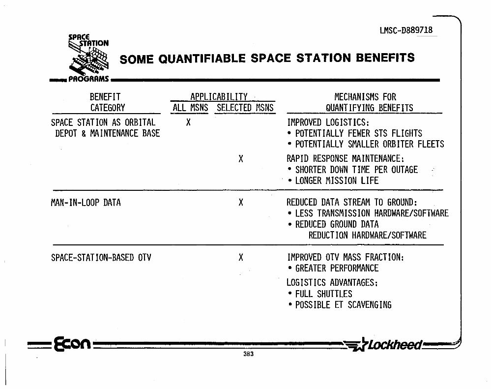
LMSC-D889718 SPACE
• SOME QUANTIFIABLE SPACE STATION BENEFITS _PAOGRRMS ______________________ _
BENEFIT CATEGORY
SPACE STATION AS ORBITAL DEPOT & MAINTENANCE BASE
MAN-IN-LOOP DATA
SPACE-STATION-BASED OTV
APPLICABILITY ALL MSNS SELECTED MSNS
X
MECHANISMS FOR QUANTIFYING BENEFITS
IMPROVED LOGISTICS: • POTENTIALLY FEWER STS FLIGHTS • POTENTIALLY SMALLER ORBITER FLEETS
X RAPID RESPONSE MAINTENANCE:
X
X
• SHORTER DOUN TIME PER OUTAGE . • LONGER MISSION LIFE
REDUCED DATA STREAM TO GROUND: • LESS TRANSMISSION HARDWARE/SOFTWARE • REDUCED GROUND DATA
REDUCTION HARDWARE/SOFTWARE
IMPROVED OTV MASS FRACTION: • GREATER PERFORMANCE LOGISTICS ADVANTAGES: • FULL SHUTTLES • POSSIBLE ET SCAVENGING

LMSC-D889718
SOME QUANTIFIABLE SPACE STATION BENEFITS (CONT'D)
In addition to the quantifiable benefits listed here, there are potential macroeconomic advantages to government spending in high technology areas. These are expected to be the focus of a forthcoming study.
384

SPACE LMSC-D889718--
SOME QUANTIFIABLE SPACE STATION BENEFITS (CONT'D) iii _PROGRAMS ______________________ _
·BENEFIT CATEGORY
TEST BED CAPABILITY
MAN-TENDED. EXPERIMENTS
TECHNOLOGY BASE FOR MANNED MISSIONS
LONG DURATION MANNED MISSION CAPABILITY
APPLICABILITY MECHANISMS FOR ALL MSNS SELECTED MSNS QUANTIFYING BENEFITS
X BRASSBOARD EXPERIMENTS FLIGHT
X
X
X
OPTION: REDUCED ANALYSISIDESIGN REDUCED TEST
REDUCED AUTOMATION~ REDUCED DATA HANDLING: HARDWARE ACQUISITION SOFTWARE DEVELOPMENT
REDUCED DDT&E FOR: MANNED PLANETARY MISSIONS OTHER ADVANCED MISSIONS
REDUCED DEMAND ON STS: POTENTIALLY SMALLER ORBITER
FLEET

LMSC-D8897l8
GROUND-BASED VS STATION-BASED OTV SERVICING
COST OF RECURRING TRANSPORTATION
A parametric approach was used in analyzing the relative costs of ground-based and. Space-Station-based servicing systems. The measure of cost was total recurring Space Transportation outlay over ten years. Concept-to-concept differences between OTV flight operations costs were judged to be small; hence, these costs were omitted. The independent variable was chosen as the average number of ITSS spacecraft serviced in a year; this figure combines the total number of spacecraft with the average frequency of servicing.
Results of this analysis show that both of the space-based OTV systems are signficantly lower in cost for ITSS servicing than the ground-based system. Moreover, these savings are of a magnitude for this one mission (roughly $2.6 billion at the high end) to offset an appreciable amount of Space Station acquisition costs.
386

lMSC-D889718
GROUND-BASED VS. STATION-BASED OTV SERVICING (COST OF RECURRiNG TRANSPORTATION). ___ PROGRAMS ________________________________________________________ ___
2 3 4 5 6
AVERAGE NO. OF SPACECRAFT SERVICED PER YEAR

..

LMSC-D88971~L __
SPACE
• ~. PROGRAMS iiiiiiiiiiiiiiiiiiiiiiiiiiiiiiiiiiiiiiiiiiiiiiiiiiiiiiiiiiiiiiiiiiiiiiiiiiiiiiiiiiiiiiiiiiiil
TASK 3 - COST AND PROGRAMMA TIC ANALYSIS
3~ *'1 BEf%JEFITS
3.2 COST, SCHEDULE AND FUNDING
U) m n -I -o z w . N

lMSC-D889718
COSTING GROUNDRUlES/ASSUMPTIONS
Emphasis in the cost analysis was on identifying cost drivers, uncertainties, and evolutionary trends. The estimates presented here cover development, production, operation and deployment of the reference lockheed Space Station evolutionary .architecture. The estimates exclude costs for development and support of Station payload costs. likewise, costs for acquisition and operation of the OTY and Te1eoperator Maneuvering System were omitted from the cost tabulations in this section even though they were used in the benefits ana1ysis~
The reference costs presented here incorporate the $83 million per flight STS user charge, while the $117 million per flight upper bo~nd was used to explore uncertainty effects. The derivation of these numbers is explained subsequently.
390

.: , t '" '·.t LMSC-D889718
SPACE
COSTING GROUNDRULESIASSUMPTIONS • __ PRO~AMS_' __________________________________________ ___
ALL COSTS IN CONSTANT 1984 DOLLARS
ONE EQUIVALENT SET OF FLIGHT HARPWARE FOR GROUND TEST , • • ! •
STS COSTS ESTABLISHED AS UNCERTAINTY BAND:
,',,' .', LOWER BOUND,= CURRENT USER CHARGE ,OF '$71M (1982) = $83M (1984)
• UPPER BOUND = EST. 1983-2000 CUM. AVG.' COSTS' = '$117M (i984)
ONLY SPACE STATION MODULES ESTIMATED:
• NO OTV COSTS
• NO TMS COSTS • NO PAYLOAD TRANSPORTATION/OPERATIONS
, ~:: . ,

lMSC-D889718
STS COST/ACTIVITY SENSITIVITIES
As noted earlier, two values of STS price per flight were used to span the uncertainty ~ange in the Space Station time frame. The lower value was the current $71 miJ1ion per flight (1982 dollars) changed to foreign and commercial users 1986-1988, as updated to 1984 dollars. Using an estimated. escalation rate of 17 percent from 1982 to 1984 dollars (PRICE model reference values) the resulting price per flight is 83 million in 1984 dollars.
The figure opposite shows how the upper bound value was derived. First, a conservative activity level of 378 STS flights for the years 1983-2000 was selected; this assumes that the combined effect of Space Station building (4 launches per year exclusive of payloads) is matched by a modest level of other STS activity and that the peak rate does not exceed 25 flights per year. A conservative acti~ity level drives price per flight upward. The 378 flight level was then entered into the ECON-derived cost/activity graph for hardware and support (left hand chart); comparable ETR launch activity levels were entered into the graph for launch and launch support (right hand chart). The resulting cost per flight is 73 million for hardware plus $27 million for launch, which totals $100 million in 1982 ~ollars, or $117 million in 1984 dollars. If these costs, which represent cumulative average cost 1983-2000, were applied as a price per flight (also a conservative assumption) then' a safe, upper bound for STS charges has been derived.
392

LMSC-D889718
STS COST / ACTIVITY SENSITIVITIES ... PROGRAMS ______________________________________________________ _
ESTIMATED CUMULATIVE AVERAGE COSTS -N 00 en HARDWARE AND SUPPORT LAUNCH -:e:: ~ -- N
00 0 en 0 r-I 0 N 90 :e:: 60
I ~ ~ -00 en :c r-I u I-
:z: 40 :::» :c S c.!:J - , ...J l-LL (I) , 0 20 I- $73M Ci) 373 FLTS u (I) 0 (2S/YR PEAK RATE) w u c.!:J
w C2 c.!:J 30 w <r: ~ a:: 400 500 600 700 800 100 200 300 400 500 w ~ NUMBER OF FLIGHTS 1983-2000 NUMBER OF ·FLI~HTS PER
LAUNCH SITE 1983-2000
LMSC-D889718
SPACE STATION PRO&RAM COSTS
This figure summarizes the incremental buildup of costs needed to implement each step of the reference Lockheed Space Station architecture. Step 1 deploys a Station that represents an initial operational capability at a cost of $2.8 billion. Steps·2 through 4 augment this capability in increments for an added cost of $2.8 billion ($5.6 billion cumulative). Step 5 adds OTV servicing capability for an added cost of $1.4 billion ($7.0 billion cumulative). Step 6 adds spacecraft servicing capability at an added cost of $1.3 billion ($8.3 bi11ion·cumu1ative). Step 7 completes the configuration and adds materials processing capability for an added $1.6 billion ($9.9 billion cumulative).
Acquisition cost drivers for the Space Station include test article philosophy (photoflight versus one or more dedicated test vehicles); relative state of the art; and inheritance (for both hardware and software). Operational cost drivers include STS resupply intervals and STS price per flight. For example, applying the upper-bound STS price .per flight of $117 million would increse the operations costs shown here by $850 million, an increase of more than 25 percent.
The influence of Space Station autonomy on life cycle cost is not completely clear. The most likely area for savings due to autonomy is in the operational cost for NCC operations, which is estimated at $50.2 million per year. However, any savings must be traded against the added acquisition costs needed to achiev~ autonomy.
394

DDT & E
PRODUCTION
OPERATIONS
TOTAL
SPACE STATION PROGRAM COSTS ($ MILLION, 1984)
LMSC-D889718
STEP 1 STEP 2 STEP 3 STEP 4 STEP 5 STEP 6 STEP 7 TOTAL
1938 129 556 392 631 321 534 4501
392 60 289 316 276 327 564 2224
511 255 255 511 511 639 456 3138
2841 444 1100 1219 1418 1287 1554 9863

LMSC-D889718
PROGRAM FUNDING PROFILE
This figure shows the funding levels for development, and operation of the Lockheed reference Space Station architecture. Costs are in millions of constant 1984 dollars. This is a composite chart that sums the funding levels for each of the seven . evolutionary steps, plus one year of steady-state operations for the all-up configurations. The one year of operations (ending December 1996) is funded at $580 million.
The assumed start of the program is October 1984 (the beginning of fiscal year 1985). This date has no significance other than in terms of the arbitrary January 1990 first-launch data shown in the LMSC evolutionary scenario. All spans and funding should be thought of as 'time zero' i.e., years from program start. In these terms, the peak funding of just under $1.5 billion occurs in the sixth and seventh years after go-ahead.
396
\

LMSC-D889718 SPACE
PROGRAM FUNDING PROFILE • ... PROGAAMS __________________________________________________________ __
TUIU n'Elln.RE SUIIIAay
COSTS II tDUAIS I JAIl 14 UIIITI .......................................................................... , '£1101 I '(1 CUT I rx'ElllnuRES roR 'EUOl I CUMULATIVE UpnlnURES I ulln I COMPLETE I ---------- ----------Ut .. 0.0 DEC IS 1.0 lEt 16 4.5 IEC 17 10.3 lEt II 17.' Irc If 27.1 IEC .0 41.1
lEt " 54.' lEt 92 66.7 ~rc n 71.1 tEt f4 17 •• tEC '5 f4.4
tEe " 100.0 ......................
TOTAL I TOTAL I -----... ------------------- -------------------------1.0 0.0 1.0 0.0
102.7 1.0 103.7 1.0 U9.' 3.5 473.3 4.5 60S.' 5.1 1071.' 10.3 752.' 7.2 IUI.7 17.6 '''.1 .. , 2831.5 27.1
1455.7 14.0 4287.3 41.1 "45.' 13.9 5733.2 54.9 122'.2 11.1 "Sf.4 ".7 1117.1 11.4 "47.2 71.1 1015.4 '.7 "61.6 17.8 691.7 ,., 9154.2 f4.4 510.2 5.' IOU4.4 100.' ................................................... ,
•••• 11 •• 111111111111.
1111111 ................. . 111I111I1I111I1I11I11I1I1il •
••• 11111111111111111111111111111 •• •• 111111111111111111111111111111111 II ....
•• • 111111111111111111111111111111111111111111111 •• 111111111111111111111111111111111111111111111111111 •• 111111
•• 11111111111111111111111111111111111111111111111111111111111111 •• 11111111111111111111111111111111111111111111111111111111111111111
•• 11111111111111111111111111111111111111111111111111111111111111111111 •• 111111111111111111111111111111111111111111111111111111111111111111111111
OCT.. tEC "
OME COUll' 2 IDMTHS
LMSC-D889718
OBSERVATIONS ON COST AND SCHEDULE
The LMSC evolutionary architecture defined in this study provides an early operational capability yet grows to provide services that bring the national Space Transporation to its full original promise. Moreover, this capability is added in increments that keep annual outlay within reasonable bounds.
398
J

LMSC-D889718 SPACE
.~ ~ OBSERVATIONS ON COST AND SCHEDULE _PROGRAMS ______________________ _
FOR THE REFERENCE LMSC SPACE STATION EVOLUTION:
• AN INITIAL CAPABILITY (STEP 1) CAN BE IMPLEMENTED FOR LESS THAN $4 BILLION (1984)
• FULL CAPABILITY (STEPS 1-7) CAN BE ATTAINED FOR LESS THAN $10 BILLION
FOR A FY1985 START1THE FUNDING LEVELS ARE:
• PEAK FUNDING LESS THAN $1.5 BILLIO~ • PEAK IN 1990-1991
DESIGN-TO-LIFE-CYCLE-COST CONSIDERATIONS:
• BEST PAYOFF IS IN REDUCING RESUPPLY COSTS ($83M - 117M/FLIGHT) • THESE SAVINGS CAN OFFSET HIGHER SUBSYSTEM DEVELOPMENT COSTS

LMSC-D889718
LOCKHEED ASSESSMENT OF SPACE STATION NEED
A space station should be initiated now for initial operations in the early 1990's. By the latter half of the 90's launch costs can be expected to be reasonable, .nd manned space operations will be routine, efficient$ and essential to the well being of the United States.
400

LMSC-D889718 SPACE
~ ~ LOCKHEED ASSESSMENT OF SPACE STATION NEED
___ PROGRAMS ________________________________________________ _
THE CAPABILITY FOR MANNED SPACE OPERATIONS IS ESSENTIAL TO THE WELL BEING OF THE UNITED STATES
A SPACE STATION PROGRAM SHOULD BE INITIATED NOW
. 401

End of Document