Embed Size (px)
Citation preview

This page has been reformatted by Knovel to provide easier navigation.
14 Aluminium
J B Dwight MA, MSc, CEng, FIStructE,MIMechEFellow of Magdalene College andEmeritus Reader in Structural Engineering,University of Cambridge
Contents
14.1 Introduction 14/314.1.1 History 14/314.1.2 Comparison with steel 14/4
14.2 Production of structural material 14/414.2.1 Primary production 14/414.2.2 Wrought products 14/414.2.3 Castings and forgings 14/5
14.3 Control of strength 14/514.3.1 Heat-treatable and nonheat-treatable
material 14/514.3.2 Heat treatment 14/514.3.3 Cold-working 14/5
14.4 Alloys 14/514.4.1 Alloy numbering system 14/514.4.2 Selected alloys – properties 14/614.4.3 Heat-treatable alloys 14/614.4.4 Nonheat-treatable alloys 14/714.4.5 Alloy selection – summary 14/7
14.5 Fabrication 14/814.5.1 Cutting and forming 14/814.5.2 Mechanical joints 14/814.5.3 Welding 14/814.5.4 Adhesive bonding 14/914.5.5 Use of extruded sections 14/9
14.6 Durability and protection 14/1014.6.1 Unpainted use of aluminium 14/1014.6.2 Protective systems 14/1014.6.3 Contact with other materials 14/10
14.7 Structural calculations 14/1014.7.1 Principles of design 14/1014.7.2 Section classification 14/1114.7.3 Resistance of cross-section 14/1114.7.4 Softening at welds 14/1214.7.5 Buckling 14/1314.7.6 Connections 14/1414.7.7 Fatigue 14/14
References 14/14
Bibliography 14/14

14.1 Introduction
14.1.1 History
Although the most abundant metal in the Earth's crust, alu-minium was ranked as a precious metal until 1890. In that yearthe modern electrolytic method of smelting was invented, whichtransformed the status of aluminium as an industrial metal.Today, it is second-cheapest, after steel, among the metalssuitable for structural use. Its volume usage roughly equals thatof all the other nonferrous metals put together.
The first strong alloy ('Duralumin') was developed in 1905,which made possible the structural use of aluminium in theGerman Zeppelins of the First World War. Between the wars itsuse was developed in aircraft, leading to a vast increase inaluminium production during the Second World War. This wasaccompanied by a dramatic decrease in cost relative to othermetals. After 1945 there was great pressure to develop freshoutlets for aluminium and many new markets were found. Bynow it is well established in a wide range of industries. Aero-space accounts for a fairly small, but important, part of the totaltonnage.
The use of aluminium for civil engineering structures waspioneered in the US during the early 1930s, the first epicexample being several 45 m dragline jibs used on the Mississipi's
levees. This was followed by the replacement of the steel deck ofthe Smith Street Bridge in Pittsburgh by an aluminium one in1933, thus uprating its load capacity. This deck lasted for over40 yr until replaced by a second aluminium one. Today, alu-minium is acknowledged as a general structural material. It ischosen for main structures in situations where its special proper-ties - low density and nonrustability - justify the extra metalcost compared with steel. Figure 14.1 shows a large aluminiumroof structure built in Malaysia. This structure is mechanicallyjointed. Welding is also now widely used as, for example, in thealuminium military bridge shown in Figure 14.2.
A much greater tonnage of aluminium is consumed in second-ary structural applications, such as maintenance gantries, glaz-ing bars, window frames, curtain walling, shopfitting, prefabri-cated buildings, greenhouses, balustrades, crash-barriers, roadsigns and lamp posts. It is also used widely in the form ofprofiled sheeting for the cladding of buildings.
Figure 14.1 Aluminium roof of 50 m diameter structure for theSelangore State Mosque, Malaysia. Tubular construction,employing special extruded node units for the joints. Tubes in6061-T6 alloy, and all other extrusions in 6082-T6. (Triodeticsystem. Courtesy: British Alcan Aluminium pic)
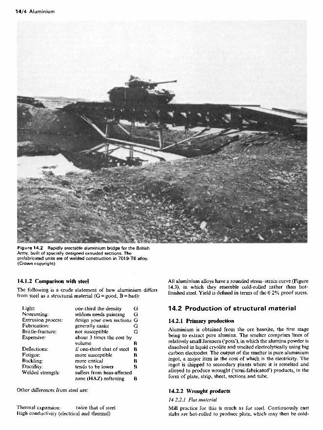
Figure 14,2 Rapidly erectable aluminium bridge for the BritishArmy, built of specially designed extruded sections. Theprefabricated units are of welded construction in 7019-T6 alloy.(Crown copyright)
14.1.2 Comparison with steel
The following is a crude statement of how aluminium differsfrom steel as a structural material (G = good, B = bad):
Light: one-third the density GNonrusting: seldom needs painting GExtrusion process: design your own sections GFabrication: generally easier GBrittle-fracture: not susceptible GExpensive: about 3 times the cost by
volume BDeflections: E one-third that of steel BFatigue: more susceptible BBuckling: more critical BDuctility: tends to be lower BWelded strength: suffers from heat-affected
zone (HAZ) softening B
Other differences from steel are:
Thermal expansion: twice that of steelHigh conductivity (electrical and thermal)
All aluminium alloys have a rounded stress-strain curve (Figure14.3), in which they resemble cold-rolled rather than hot-finished steel. Yield is defined in terms of the 0.2% proof stress.
14.2 Production of structural material
14.2.1 Primary production
Aluminium is obtained from the ore bauxite, the first stagebeing to extract pure alumina. The smelter comprises lines ofrelatively small furnaces ('pots'), in which the alumina powder isdissolved in liquid cryolite and smelted electrolytically using bigcarbon electrodes. The output of the smelter is pure aluminiumingot, a major item in the cost of which is the electricity. Theingot is shipped to secondary plants where it is remelted andalloyed to produce wrought ('semi-fabricated') products, in theform of plate, strip, sheet, sections and tube.
14.2.2 Wrought products
14.2.2.1 Flat material
Mill practice for this is much as for steel. Continuously castslabs are hot-rolled to produce plate, which may then be cold-

reduced to make strip, from which sheets are cut. The coiledstrip can be roll-formed to produce cold-rolled sections (lesscommon than in steel) or profiled sheeting.
14.2.2.2 Sections
Hot-finished sections are made by a radically different techniquefrom steel, namely extrusion. Cast billets are heated and insertedinto a horizontal extrusion press, where they are forced throughan aperture in a die, the emerging sections having a cross-sectiondetermined by the shape of the aperture. The process is highlyflexible, and the die charge is minute compared with the cost ofrolls for a steel section. It is common practice for a customer toorder new sections to meet his special requirements. The com-plexity of possible profiles is almost unlimited. Hollow shapesare readily extruded.
14.2.2.3 Tubes
Normally tubes are produced as hollow extrusions. Thin tubing,e.g.irrigation pipe, can be formed from strip by welding. Alter-natively, thin tubing for precision use may be produced asdrawn tube, at greater cost.
14.2.3 Castings and forgings
Aluminium castings (see section 14.4.4.5) may be employed inconjunction with wrought material, typically for small fittingsand attachments. They may be sand-cast, or else chill-cast (forlarger quantities). Aluminium forgings can fill a similar rolewhen better strength and ductility are needed.
14.3 Control of strength
14.3.1 Heat-treatable and nonheat-treatable material
Nearly all the aluminium alloys, unlike steel, are unacceptablyweak in the hot-finished state. There are two main kinds ofalloy: (1) 'heat-treatable'; and (2) 'nonheat-treatable'. The pro-ducer strengthens the former by heat treatment, and the latterby cold-working. The heat-treatable alloys are generally thestronger, but less tough, and are more often the choice for mainstructural use. The nonheat-treatable alloys typically appear inthe form of sheet, for which the necessary cold-working isprovided during manufacture by the reduction in the rollingoperation. Either type can be softened again by annealing.
It is essential for extrusions to be in heat-treatable alloy, sincethere is no way of cold-reducing them during manufacture.Drawn tube can be of either type.
14.3.2 Heat treatment
The strengthening process for heat-treatable alloys consists ofquenching ('solution treatment') followed by ageing. Thequench has little immediate effect, but with time the metal willgradually harden at room temperature, reaching its finalstrength after several days. Such material is said to be 'quenchedand naturally aged'.
The ageing process is speeded up usually by heating the metalin a furnace for some hours at about 150 to 20O0C ('precipi-tation treatment'). Such material is stronger than if naturallyaged. It can be described as 'quenched and artificially aged', ormore commonly as 'fully heat-treated'.
The quench ideally takes place from a carefully controlledtemperature in the region of 50O0C. The resultant distortion hasto be corrected, usually by stretching (before artificial ageing).With wide, thin, extrusions distortion is a major problem, and
may well dictate the thickness and, hence, economy of a design.A common practice with the 6000-group alloys is to spray-quench thin extrusions as they emerge from the die, which ismore economic and causes less distortion than if they wereheated and quenched in a tank as a subsequent operation. Forvery slender profiles in the 6063 alloy it is even possible to turnoff the water entirely and rely on an air-quench at the die,thereby reducing distortion even more. Ideal quenching isobviously not achieved with air-quenching and the resultingmaterial has reduced properties.
14.3.3 Cold-working
Nonheat-treatable aluminium material is strengthened bymeans of cold-working applied during manufacture. This ispossible for products that are cold-reduced in bringing them totheir final thickness, i.e. sheet and drawn tube. It is also possible,to a lesser degree, for plate at the lower end of the thicknessrange ('cold-rolled plate').
The required properties are achieved by careful control of thereduction passes and of interpass annealing. It is common torefer to cold-worked material as being one-quarter, one-half,three-quarters or fully hard, as an indication of its 'temper', i.e.of the extent to which it has been strengthened. The strongesttemper is fully hard, but a lower temper may be called for whenformability is a factor. For the stronger of the nonheat-treatablealloys the fully-hard temper is not offered.
14.4 Alloys
14.4.1 Alloy numbering system
The specification of aluminium materials has been much simpli-fied by the recent worldwide adoption of the US numberingsystem. Engineers should abide by this and use no other.
A given alloy, i.e. composition, is referred to by a four-digitnumber, the first digit of which indicates the alloy group towhich it belongs. The alloys are grouped according to mainalloying elements as follows, the groups of interest to civilengineers being given asterisks:
Heat-treatable alloys: 2000 group Copper*6000 group Magnesium
plus silicon*7000 group Zinc
Nonheat-treatable alloys: 1000 group (Pure)*3000 group Manganese4000 group Silicon
*5000 group Magnesium
Apart from the alloy it is necessary to specify the condition (heattreatment or temper). This is done by means of appropriatesymbols written after the alloy number. For heat-treatablealloys:
T6 Fully heat-treated, i.e. quenched and artificially agedT5 Air-quenched and artificially aged (extrusions)T4 Quenched and naturally aged
For nonheat-treatable alloys:
H12 or H22 Quarter-hard temperH14 or H24 Half-hard temperH16 or H26 Three-quarter-hard temperH18 or H28 Fully hard temper

For all alloys:
O AnnealedF As-extruded or as-rolled
Thus, typical material specifications would read as follows:
6082-T6 An alloy with a particular aluminium-magne-sium-silicon composition, in the fully heat-treated condition
3103-Hl4 An alloy with a particular aluminium-manga-nese composition, in the half-hard temper
In the temper designation for nonheat-treatable alloys the firstdigit after the H (1 or 2) is of academic interest to the averageuser; it merely shows whether the material has been cold-reduced to the final temper, or has been partly annealed after thelast pass. What matters is the ensuing digit (2, 4, 6 or 8) whichindicates the actual hardness.
The F-condition is ill-defined. It essentially refers to hot-finished material (extrusion, plate) that has received no furthertreatment, the properties of which cannot be specified closely.
14.4.2 Selected alloys - properties
14.4.2.1 Strength values
Table 14.1 gives a short list of structural aluminium materialsthat are of interest in civil engineering. The quoted mechanicalproperties are based on BS 147O1 (flat products) and BS 14742
(extruded sections). The reader is urged to refer to these or othernational standards for fuller information.
14.4.2.2 Physical properties
Approximate values roughly applicable to all aluminium alloysare as shown in Table 14.2. Weight of aluminium material maybe estimated using the following formulae:
Weight of section (N/m) = 0.027 x area in square millimetresWeight of plate (N/m2) = 27 x thickness in millimetres
Table 14.1 Selected structural alloys
Table 14.2
Density 2.7 g/cm3
Modulus of elasticity E 70 kN/mm2
Shear modulus 26 kN/mm2
Poisson's ratio // 0.33Linear expansion coefficient 24 x 10 ~6 per 0CMelting point 66O0C
14.4.3 Heat-treatable alloys
14.4.3.1 2000-group
This group of alloys, sometimes referred to as 'Duralumin', istypified by a high copper content (around 4%). It includes mostof the strong alloys used for aircraft, an example being 2014-T6with a tensile strength approaching 450 N/mm2. These alloys areseldom used outside the aerospace industry, because of their lowductility in the T6 condition, higher cost, inferior corrosionresistance and nonweldability. They have to be fabricated withgreat care. To reduce corrosion it is possible to use them in theform of 'clad sheet', a product with rolled-on pure aluminiumfacings.
14.4.3.2 6000-group
This very important group, covering aluminium alloyed withmagnesium and silicon, essentially comprises two basic gradesof alloy: (1) a stronger; and (2) a weaker grade. The strongercomes in slightly different versions in different parts of theworld, the European version, 6082, being broadly similar to the6061 more commonly used in North America. Material of thistype in the T6 condition may be regarded as the 'mild steel' ofaluminium, and is the commonest choice for general structuraluse. It has a 0.2% proof stress about equal to the yield of mildsteel, although with a lower tensile strength and less ductility. Itis readily welded, but with nearly 50% loss of strength in theheat-affected-zone (HAZ) (Figure 14.3). A particular feature isthe ease with which these alloys can be extruded into thinintricate sections.
The second type of alloy in the group is 6063, which isconsiderably weaker. This is the extrusion alloy par excellence
Approximate% composition
Heat-treatableZn4.0, Mg2.0MgO.9, Si 1.0, MnO.7
MgO.7, SiO.4MgO.7, SiO.4
Nonheat-treatableMg4.5, MnO.7Mg4.5, MnO.7Mg2.0, MnO.3MnO.6, MgO.5
Alloy and condition
7019-T66082-T6
6063-T66063-T5
5083-05083-H225251-H243105-H18
Form
E, PE, SPEE
PPSS
>m(mm)
2025
25
663
Minimum properties/O
(N/mm2)
330255240160110
125235175190
/.(N/mm2)
380295295185150
275310225215
elong.(%)
88888
1485
1-2
Design stressesPo(N/mm2)
330255240160110
105235175190
Pa(N/mm2)
355275265170125
145270200200
Notes:f0 = 0.2% proof stress, fu = tensile strength.E = extrusion, P = plate, S = sheettm — maximum thickness for which stresses are valid.The following are similar to the 6082 alloy, but are slightly weaker: 6061, 6081, 6181, 6261, 6351.The alloy 3103 is similar to 3105, but again slightly weaker.

Figure 14.3 Typical stress-strain curves. f0=Q.2% proof stress(even better than 6082) and is the automatic choice for slendercomplex architectural shapes, such as window sections andcurtain-wall mullions, where stiffness rather than strength isimportant. Another feature is its smooth surface finish (with awell-made die). Extrusions in 6063 can be produced in thenormal T6 or else in the weaker T5 condition (air-quenched),the latter being suitable for very slender profiles that would nototherwise be feasible; 6063 is not supplied in the form of plate orsheet.
14.4.3.3 7000-group
This group, comprising aluminium alloyed with zinc and mag-nesium, was originally developed in the form of ultra-strongmaterials for use in military aircraft, having tensile strengthsexceeding 500 N/mm2. Of value to the civil engineer are the less-strong alloys 7020 and 7019, which are of special interest forwelded construction. With these, the heat-affected materialadjacent to a weld gradually regains strength over a period atroom temperature, and after a month gets back to 75% or moreof the full T6 properties. Both alloys extrude nearly as well as6082. The weaker version 7020 has comparable strength to 6082in the T6 condition, while 7019 is up to 30% stronger.
Material of 7000-type is susceptible to stress corrosion, whenthe amount of the alloying elements exceeds a critical level. Thealloy 7020 was developed and standardized in Europe with thisdanger taken into account. As a result it is safe, but hardly anystronger than the cheaper and more readily available 6082. Thestronger 7019 version would seem more attractive to a designer.However, 7019, being more highly alloyed, is closer to thecritical level for stress corrosion. It was developed in the UK formilitary bridges, in which form some 1500Ot have been usedsatisfactorily. But this success was only achieved by very carefulcontrol of fabrication procedures. It is essential for an intendinguser to realize that 7019 is not as simple to fabricate as 6082 or6061, and to seek advice before doing so.
14.4.4 Nonheat-treatable alloys
14.4.4.1 1000-group
This comprises nominally pure aluminium with different levels
of guaranteed purity, material too weak for serious structuraluse. The cheapest version is 1200 with a minimum aluminiumcontent of 99.0%. Higher purities are available, and in theannealed condition these can provide a valid alternative to leadas a soft flashing material.
14.4.4.2 3000-group
This covers material with manganese as the main alloyingelement. The two common versions are 3103 and 3105, of which3105 is slightly the stronger. Used in the fully hard H18 temper,they represent the standard type of material used for profiledaluminium sheeting as employed for cladding of buildings.
14.4.4.3 4000-group
The only interest here in this minor group (aluminium plussilicon) is that it includes one type of weld filler wire.
14.4.4.4 5000-group
This comprises a range of alloys having varying amounts ofmagnesium as the main alloying element. They are characterizedby their ductility and toughness. They are generally unsuitablefor use as extruded sections.
The most important in structural terms is the strongest(5083), a plate material. Until recently this was supplied either inthe annealed O condition, or else in the indeterminate F con-dition (as-hot-rolled). Its use was confined to low-stress applica-tions, where toughness rather than high yield was needed as, forexample, for the entire superstructure of the liner Queen Eliza-beth II. Material 5083-0 has too low a proof stress (only125 N/mm2) for use in highly stressed structures; 5083-F willoften have a proof stress 40% higher, but this cannot beguaranteed and the designer must still work to the low0-condition properties. Recently, 5083 plate in thicknesses up to6 mm has become available in the H22 temper; in this conditionit becomes much more attractive, its properties matching thoseof 6082-T6 for which it is a valid replacement.
Other 5000-group alloys in decreasing order of strength are5154A, 5454 and 5251. They are typically used in the mediumtempers, where their combination of formability and toughnessmakes them suitable for boatbuilding and sheet metal fabrica-tions generally.
14.4.4.5 Casting alloys
A useful casting alloy contains aluminium with a nominal 12%Si (known as LM6 in the UK). This has a tensile strengthroughly comparable to that of 6063-T6, but with a proof stress50% lower. It has excellent foundry characteristics and goodductility. An alternative is the Al-5% Mg alloy (known as LM5)which is better in terms of surface finish, but which can only becast into simple shapes; it is less ductile and slightly weaker thanLM6.
14.4.5 Alloy selection - summary
For highly stressed welded construction the ideal choice is 7019-T6, because of its good strength and less severe degree of HAZsoftening. But it is vital to realize that this is not a material foramateurs in anything but the simplest fabrications because ofthe latent risk of stress corrosion if correct procedures are notfollowed.
A more common choice is 6082-T6 or 6061-T6, which issomewhat weaker but more straightforward to fabricate. HAZsoftening at welds is more severe than with 7019, and this callsfor ingenuity in the location and design of joints.
7019-T6
Grade 43 steel
5083-0
6082-T6
0.01
(N/mm2)
300
For welded stiffened plating where toughness is needed, thenormal choice would be 5083-F plate welded to 6082 (or 6061)-T6 extruded stiffeners. At thicknesses up to 6mm the plate isavailable as 5083-H22 with higher and more precise properties.
For triangulated structures (trusses, space frames) the normalchoice is 6082 (or 6061)-T6. Mechanical joints are often used,instead of welding, to avoid the problem of HAZ softening. Forextruded members whose design is governed by stiffness ratherthan strength, as for intricate architectural profiles, the naturalchoice is 6063-T6. If the section is on the limit of feasibility dueto its slenderness, the weaker condition 6063-T5 has to be usedinstead.
Profiled sheet used for the cladding of buildings is normallysupplied in 3105-H18 or the slightly weaker 3103-H18.
Sheet metal fabrications of secondary importance can bereadily made in 5251-H14 which is ductile and formable. Purealuminium in the form of 1200-H14 can be useful for unstressedsheet-metal work. Pure aluminium is also employed, in higherpurities, for chemical plant (as an alternative to stainless steel)and for electrical conductors (busbars and transmission lines).
A good general-purpose casting alloy is the Al-12% Si(known as LM6).
14.5 Fabrication
14.5.1 Cutting and forming
14.5.1.1 Cutting and machining
Thin material can be sheared like steel, but more readily. Forthicker material cold-sawing is used, with either a circular orband saw. Aluminium (except in the softest tempers) can besawn faster than steel, especially if suitable coarse-toothed sawsare used.
Aluminium is also more readily machined than steel, and it isnot unusual in design to employ extrusions incorporatingattachment flanges which are machined away over the greaterlength of the member. (Stiffened panels in aircraft are oftenmachined out of the solid.)
Ordinary flame-cutting is unsuitable for aluminium, becauseof the ragged edge produced. Instead, one can employ plasma-arc cutting, an adaptation of the tungsten inert gas (TIG)welding process.
14.5.1.2 Bending
The heat-treatable alloys in the full strength T6 condition areless easily manipulated than steel. They will only accept a smalldeformation when bent cold, due to their lower ductility.Heating, on the other hand, disturbs the heat treatment andcauses severe softening. One solution is to form the material inthe more ductile T4 condition and then bring it up to the full T6strength by subsequent artificial ageing in a low-temperaturefurnace.
With the nonheat-treatable alloys the practice for forming ismore as for steel. Cold-bending is employed when possible, thetemper of the material being selected to suit the severity of thebend. Springback is more than for steel. For severe manipula-tions it is possible to apply local heating with a gas flame, thenecessary temperature being 450 to 50O0C. Great care is neces-sary to avoid overheating the aluminium, since there is nocolour change at this temperature. Temperature-sensitivecrayons may be used; alternatively one can rub a pine stick onthe heated area and see if it leaves a mark.
14.5.2 Mechanical joints
74.5.2.7 Riveting
For many years, riveting was the normal means of making shop
joints in aluminium. More recently there has been a wholesalemove to welding, even for structures in the 6000-group alloyswhich are severely affected by HAZ softening. Riveting is littleused and rivets have become hard to get. One wonders if theswing to welding has not been overdone.
Small solid rivets would usually be in 5154A alloy with thesmall 'pan' head driven cold. Squeeze riveting is preferred tohammering. Larger rivets can be driven hot. Alternatively, onecan use 6082-T4 rivets (or equivalent) which have been held in arefrigerator since quenching, to suppress natural ageing. Theseare readily driven cold, after which they age-harden in positionto attain their proper T4 strength.
Proprietary fasteners such as 'Pop' and 'Chobert' rivets areavailable for joints in sheet-metal work. These are suitable forblind riveting, i.e. from one side, and are quick to use.
14.5.2.2 Bolting
Aluminium structures can be assembled using either ordinarybolting (dowel action) or high-strength friction-grip (HSFG)bolting (friction action).
Ordinary bolding is used with clearance or close-fittingreamered holes as appropriate, possible bolt materials being:6082-T6 aluminium (or equivalent), steel (suitably coated) orstainless steel (316Sl 6 or 304Sl 5). Aluminium bolts are nonetoo good in tension, especially in fatigue. On the other hand itmay be difficult to get steel bolts with a coating of sufficientdurability to match that of the aluminium, unless they arepainted. The ideal answer is stainless steel, which is usuallyworth paying for.
In recent years it has become acceptable to employ HSFGbolting for aluminium, taking care with the protection of thesteel bolts. Bolt material (high yield steel) and torqueing proced-ures follow HSFG practice in steel. Proper attention must, ofcourse, be paid to the condition of the contact surfaces, whichshould be grit-blasted. The slip resistance can be improved byapplying epoxy resin (HSFG bolting is not recommended foruse on plates having a 0.2% proof stress under 230 N/mm2).
14.5.2.3 Screwing
Tapped holes in aluminium tend to be unsatisfactory. Patentstainless-steel thread-inserts are available, which give goodservice on parts that have to be screwed and unscrewed repea-tedly.
14.5.3 Welding
14.5.3.1 Welding processes
Alloys in all groups except 2000 are readily welded. Unfortu-nately, welding is accompanied by local HAZ softening. Thisoccurs to a greater or lesser degree depending on the parentalloy (see section 14.7.4), except with annealed material.
The standard arc-welding process is manual inert gas (MIG),using d.c. current. This is similar to CO2 welding of steel exceptthat the shielding gas is argon (or helium in North America). Itis easy to operate and ideal for positional welds. It can be usedon thicknesses down to about 2mm. With the MIG process,aluminium can be welded as easily as steel, after an initialtraining period. Current settings are higher and deposit areastend to be greater.
For thin work the TIG process is used instead pf MIG. In thisthe arc is struck from a nonexpendable tungsten electrode, thefiller wire being held in the left hand. This is an a.c. processwhich needs more skill than MIG. It is slower and causes moredistortion.
Aluminium can be spot-welded, but with .higher energy inputsthan for steel.

14.5.3,2 Filler wire
Simplified recommendations for selection of arc welding fillerwire material are shown in Table 14.3. For further informationrefer to BS 3019 or 3571.3
Table 14.3
Parent alloy group Filler composition
6000* 5% Si (4043A), or 5% Mg(5056A, 5356)
5000 or 7000 5% Mg (5056A or 5356)3000 or 1000 Parent composition
Note:*When welding 5000 to 6000 use the 5% Mg wire.
14.5.4 Adhesive bonding
Aluminium is eminently suitable for glued joints using epoxyresin, a technique successfully used for lamp posts and othercomponents. The epoxies are attractive because of their abilityto tolerate poor fit-up. Shear strengths up to 15 N/mm2 can bedeveloped, but it is essential to guard against premature failuredue to peeling from the end of a connection. An extrudedtongue-and-groove feature is often a good way of preventingthis.
The resin can be used cold or, alternatively, can be hot-curedto give improved strength. In the latter case the curing tempera-ture is the same as that needed for artificial ageing. Thus, withheat-treatable alloys it is economic to order the material in theT4 condition, and rely on the hot-curing operation to hardenthe aluminium (up to T6).
14.5.5 Use of extruded sections
74.5.5./ Availability
The relatively low cost of extrusion dies often makes it economicto design one's own section or 'suite' of sections to suit the job inhand. The use of such sections can reduce fabrication costs andproduce an improved final product provided, of course, thequantities are sufficient.
Extrusion is mainly confined to the 6000 and 7000 alloygroups, the order of merit for extrudability being: (1) 6063;(2) 6082 or 6061; and (3) 7019 or 7020. Complex sections,including hollows, are produced in all of these. Extrusions are
also possible in 2014 (high-strength) and 5083 (high-ductility),but with severe limitations on profile and at much higher cost.
Hollow sections are normally produced using a 'bridge die' inwhich a mandrel, defining the internal shape, is supported onfeet locating on the body of the die (which defines the outershape). Since the hot plastic metal has to flow around these feetand reunite, the final section contains longitudinal welds. Thesecannot be seen and, in the vast majority of applications, arequite acceptable. But there are some situations where theywould be regarded as a potential danger. Hollow sectionsextrude more slowly than nonhollows, and thus cost more perkilogram; the die charge is also higher.
Apart from custom-made profiles, the designer has a widerange of conventional sections from existing dies to choosefrom, such as channels, angles, T- and !-sections and boxes.Stockists hold these, usually in 6082-T6 or equivalent.
Sections are extruded in long lengths and can be supplied upto 20 m long to meet special needs. The normal limit on length ismuch less than this and is dictated by handling and transport.
14.5.5.2 Limiting dimensions
Sections generally are available up to about 300 mm wide fromsmall and medium extrusion presses. With large presses, usingspecial die assemblies, it is possible to extrude sections up to600 mm wide, depending on the shape. But relatively few millscontain such equipment.
The designer often wants a section to be as thin as possible,for economy. In 6063 alloy the lower limit on thickness can veryroughly be taken as the lesser of 1.0 mm and width/120. In 6082(or equivalent) the corresponding values are l.5fmm andwidth/80, while in 7019 they are somewhat more. Sections of6063 at the limit of slenderness can be supplied in the T5condition (air-quenched) to reduce the amount of post-extru-sion straightening needed to correct distortion.
14.5.5.3 Section design
Figure 14.4 shows a few of the devices that can be incorporatedin the design of extruded shapes. Figure 14.4(a) shows a lippedchannel space-frame chord, which is a more efficient shape thana plain (unlipped) channel, having greatly increased local buck-ling resistance. The planking section (Figure 14.4(b)) incorpor-ates various features, including integral stiffeners, interlock, andanti-slip surface. Planking sections, first developed as flooringfor trucks, have also been employed in bridge decks and (afterpiercing) for open-work flooring. Figure 14.4(c) shows a double-sided planking section, again interlocking.
Figure 14.4 Examples of extruded sections

14.6 Durability and protection
14.6.1 Unpainted use of aluminium
14.6.1.1 The corrosion process
Atmospheric corrosion of unprotected aluminium proceeds bylocalized pitting, a radically different process from the rusting ofsteel. The oxide corrosion products formed at the pits arevoluminous, giving an exaggerated impression of the actualdamage. The rate of attack, defined by the depth of pitting,becomes stifled by the corrosion products and slows down afterthe first 2 or 3 yr. In outdoor sites the corrosion is less when thesurface is regularly washed or rained on.
Corrosion failures, on the rare occasions that they happenwith aluminium, usually stem from contact with other materials(see section 14.6.3).
14.6.1.2 Durability rating
Aluminium will usually last for ever unprotected, even out ofdoors. The decision whether or not to paint in an exposedenvironment depends on the durability rating of the alloy asshown in Table 14.4.
Table 14.4
Rating Alloy groups Whether to paint
A 1000, 3000, 5000 Usually no needB 6000 Only necessary when exposed
to severe industrial ormarine environment
C 2000, 7000 Generally necessary, except indry unpolluted situation
14.6.2 Protective systems
14.6.2.1 Conventional painting
When an aluminium structure has to be painted, it is importantthat the priming and subsequent coats contain no copper,mercury or graphite, and preferably no lead. A zinc chromatepriming coat is recommended.
14.6.2.2 Powder coating
In recent years, powder coating has become an economicprocess for the coating of aluminium components, on a mass-production basis, and has to some extent replaced anodizing.The powder is sprayed on and stoved, the resulting coat havinga more even thickness than with solvent-based paint. Compo-nents are often powder coated for purely decorative purposes.
14.6.2.3 Anodizing
This is a process whereby the inherent oxide film is artificiallyincreased electrolytically, the minimum oxide thickness for'architectural anodizing' being 25 um. This gives a pleasant satinappearance, which will last for years if regularly washed. Colouranodizing is also available, but only in a limited number ofshades.
14.6.3 Contact with other materials
When aluminium is in direct contact with certain other metalsunder moist conditions, the adjacent aluminium gets eatenaway. This is known as 'electrolytic' or 'galvanic' corrosion.
Failure to take suitable precautions is likely to cause serioustrouble.
Such corrosion occurs when aluminium is in contact withsteel (other than stainless) or cast iron and, more severely, withcopper, brass and bronze. The attack can be stopped bypreventing direct contact, either by means of bituminous paint,or preferably with an interposed tape or gasket. Electrolyticcorrosion need not be a problem if suitable precautions aretaken.
With copper the electrolytic effect is so strong that waterdripping off a copper roof on to aluminium sheeting will quicklyperforate the aluminium, because of dissolved copper ions. Theaction between aluminium and lead is only slight. When alu-minium and zinc are in contact it is the zinc that suffers.Galvanized bolts in an exposed aluminium structure tend to losetheir protection more quickly. Aluminium that is to be embed-ded in concrete should be protected with bituminous paint;otherwise it will suffer attack while the concrete is 'green'.
14.7 Structural calculations
14.7.1 Principles of design
14.7.1.1 Codes of practice
At the time of writing (1987) existing codes for aluminiumdesign are in the process of being redrafted into limit stateformat. In the UK, BS 8118 Structural use of aluminium which isnear to publication and due to replace CP 118:1969, will be intwo parts. Part 1: 'Code of practice for design' and Part 2:'Specification for materials, fabrication and protection'. Thesimplified design rules given below have been broadly based onthe draft to Part 1, which is still subject to possible alteration.
14.7.1.2 Basic requirements
All structures should satisfy: (1) the ultimate, and (2) theserviceability limit state. Fatigue may also be a factor (seeSection 14.7.7).
14.7.1.3 Ultimate limit state
Every component, i.e. member, joint, must satisfy the following:
Action under factored loading ̂ factored resistance
where action means moment or force, as appropriate, resistancemeans ability to withstand that action, factored loading isnominal loading x yf and factored resistance is calculated resis-tance/^.
The partial factor yf, applied to the nominal working loads, hasbasic values as follows:
Dead loads 1.20Imposed loads (except wind) 1.33Wind loads 1.20
However, when more than one imposed or wind load actssimultaneously it is permissible, in the case of that whichproduces the second, third or fourth most severe action, tomultiply the basic value by 0.8, 0.6 or 0.4 respectively.
The partial factor ym, applied to the ideal calculated resis-tance, is taken thus:
Members JointsNonwelded construction 1.20 1.25Welded construction 1.25 1,30

14.7.1.4 Limiting design stresses
Resistance calculations (see sections 14.7.2 to 14.7.5) involve theuse of limiting stresses p0 and/?fl, listed in Table 14.1 for selectedalloys. p0 is usually taken to be equal to the guaranteed 0.2%proof stress. However, a reduced value is taken for materialshaving a high ratio of ultimate to proof stress, such as 5083-0,for which the stress-strain curve tends to be more rounded. Thisis to prevent plastic deformation at working load.
14.7.1.5 Combined actions
When a member carries simultaneous axial load and moment,the ultimate limit state is satisfied if:
P/PR + M/MR^1.0
where P and M are actions arising under factored load and PRand MR are the separate factored resistances.
14.7.1.6 Serviceability limit state
The requirement is that recoverable elastic deflection undernominal (unfactored) loading should not exceed the specifiedlimiting value. In view of the lower modulus it is common toaccept larger deflections in aluminium than those normal withsteel.
14.7.2 Section classification
14.7.2.1 Compact and slender sections
The first step in checking a member for the ultimate limit state,except in simple tension, is to establish whether it has a compactcross-section. If, instead, it is of slender section, the resistancewill be reduced by premature failure due to local buckling.
14.7.2.2 Classification for axial load or moment
The plate elements comprising a section are of two basic sorts:outstand and internal (Figure 14.5). The procedure for classify-ing the section is as follows:
(1) Determine the parameter /?/£ for each of the elementscomprising the section (except the tension flange of a beam).ft depends on the width: thickness ratio b: t as follows, with bmeasured to the toe of the root fillet (if any):
Plain outstand element, uniformcompression 0=b:t
Internal element, uniform compression fl=b:tWeb of beam, neutral axis at centre /?=0.356: tand £ = J25Q/p0 with p0 in newtons per square millimetre(Table 14.1).
(2) Classify the individual elements, according to the value of0/e, in Table 14.5.
Table 14.5
Outstand Internal
Element instrut Compact ^7(6) ^22(18)
Slender >7(6) > 22(18)
Element inbeam Fully compact ^ 6(5) ^18(15)
Semi-compact ^ 7(6) ^ 22( 18)Slender >7(6) > 22(18)
The values in brackets represent the tighter limitsapplicable to welded elements.
(3) The classification of the section is then taken as that of theleast favourable element.
14.7.2.3 Reinforced outstand elements
The ability of outstands to resist local buckling can be increasedby stiffening the free edge with a lip or bulb (Figure 14.5). Forsuch an element, if reinforced by a standard lip of thickness /equal to that of the plate, a more favourable value of ft may betaken as follows:
P=(b:t){\ + 0.03(c:/)3}-'/3 (14.1)
where c is the internal lip height (Figure 14.5).
If c is large, there is the chance of the lip itself bucklingprematurely as a plain outstand, and this should be checked.With any other shape of reinforcement, ft should be found byreplacing it with an equivalent standard lip (thickness /)» theinertia of which about the mid-plane of the plate is the same asthat for the actual reinforcement.
(Note: In channel-section struts it is immaterial if lips face inor out. But in a beam any lip on the compression flange must beinward facing to be effective.)
14.7.2.4 Classification for shear force
This depends on the depth: thickness ratio d: t of the web orwebs and on e (defined in section 14.7.2.2), as follows:
Compact d: t ̂ 49eSlender d:t>49e
14.7.3 Resistance of the cross-section
14.7.3.1 Axial load resistance
The factored resistance PR of an unwelded section is found asfollows:
Figure 14.5 Plate elements as considered for local buckling,(a) Outstand (plain and reinforced): (b) internal element

Tension: PR = lesser ofpaAJym and p0A/ym (14.2)
Compression (with overall buckling prevented):
Compact, unwelded section PR=p0A/ym (14.3a)
Other sections P*=P0AJym (14.3b)
where pa, p0 = limiting design stresses (Table 14.1), A, An = grossand net section areas, Ae = area of effective section (see sections14.7.3.3, 14.7.4.4) and ym = partial safety factor (see section14.7.1.3).
14.7.3.2 Bending moment resistance
The moment resistance MR of an unwelded section in theabsence of lateral-torsional buckling, is found thus:
Fully compact, unwelded section MR=p0S/ym (14.4a)
Fully compact, welded section M^=p0SJym (14.4b)
Semi-compact, unwelded section MR=p0Z/ym (14.4c)
Other sections MR=p0ZJym (14.4d)
where S and Z are plastic and elastic section moduli and S6, Zeare the same for the effective section (see sections 14.7.3.3 and14.7.4.4).
14.7.3.3 Effective section
For sections classified as slender (see section 14.7.2.2) the effectof local buckling is catered for by basing the section properties(A6 and Ze) on an effective section, instead of the true one. Inunwelded construction the effective section is found by taking athickness of kL times the true thickness for any slender elementwithin the section. kL is read from Figure 14.6, the quantities /?and e needed to enter which are as defined in sections 14.7.2.2and 14.7.2.3.
The effective section to be used for welded members, to allowfor HAZ softening at welds, is defined in section 14.7.4.4.
14.7.3.4 Shear force resistance
The factored shear resistance KR is found thus for sectionshaving unwelded compact webs, normally orientated:
V* = ̂ PoAJym (14.5)
where Av is the web area.
For unwelded webs classified as slender (see section 14.7.2.4) thefollowing formula may be used:
_ 600 x \WAVR (d:tYym (14.6)
For welded webs, refer to section 14.7.4.4. Note that Equation(14.6) becomes oversafe if applied to very slender stiffened webs.
14.7.3.5 Moment and shear combined
The moment resistance is unaffected by the presence of a shearforce V not exceeding half the value of VR. For higher values ofK, MR becomes reduced as follows:
Figure 14.6 Local buckling factor /CL for slender plate elements,(a) Outstand: (b) internal. N = unwelded, W=welded
14.7.4 Softening at welds
14.7.4.1 Severity of softening
In welded construction the designer must allow for the localsoftening that occurs in the HAZ adjacent to welds, except whenthe parent metal is in the annealed (O) condition. It is assumedthat within a certain distance of each weld the material proper-ties are reduced to the parent properties multiplied by a soften-ing factor /c,, which depends on the alloy as follows:
7000-group, T6 condition k, = 0.75
MR== M1^l-8(F/KR-0.5)3} (14.7)
where M^ is the factored resistance in the absence of shear.

6000-group, T6 condition kz = 0.55
CAAA j tensile strength in O condition5000-group k = -—-.— * . A Tz tensile strength in temper used
14.7.4.2 Extent of the HAZ
The area over which the material properties are thus reduced(the HAZ) is assumed to extend a distance z from a weld,measured: (1) transversely from the centre of a butt weld or theroot of a fillet; and (2) longitudinally from the end of any weld.Provided welding is by the MIG process, with rigorous thermalcontrol (see below), z may be generally taken as the lesser of twovalues found as in Table 14.6, where /, is the average thicknessof the plates joined (but not exceeding 1.5/2), and J2 is thethinnest plate thickness. But note that these values becomeunreliable if: (1) I2 exceeds 25 mm; or (2) longitudinal weldshave a total deposit area exceeding 3% of the gross area of thesection for 7000- or 5000-group alloys, or 4% thereof for 6000-group.
Table 14.6
Butt Fillet
7000-,5000-groups 4.5/, or 35 mm (4.5/2
2//,) or 35 mm6000-group 3/, or 25 mm (3/2
2/O or 25 mm
It is important to exercise rigorous thermal control duringwelding to limit the extent of the HAZ. The values of z givenabove are only valid if the metal temperature adjacent to a weldat the start of deposition, of any pass, does not exceed 4O0C (for7000- and 5000-group parent alloys) or 5O0C (for 6000). If thesetemperatures are exceeded, the predictions in section 14.7.4.2will underestimate the affected area. Also, with 7000-groupmaterial the softening factor k, may drop below 0.75.
14.7.4.4 Effective section of welded members
To allow for the effects of HAZ softening, the true section isreplaced by an effective one, which is assumed to have fullparent properties throughout, but with reduced thickness in theHAZs. The resistance is then found generally as in section14.7.3, using section properties based on the effective section:
(1) Compact sections. The effective section is obtained by takingan assumed thickness in the HAZ equal to kzt instead of thetrue thickness t.
(2) Slender sections. For any plate element that is both slenderand affected by welding, the assumed thickness is taken asthe lesser of kzt and kLt in the HAZ and as kLt elsewhere inthat element. The rest of the section is treated according to(1) above or section 14.7.3.3 as appropriate.
The shear resistance of a welded web of slender proportions maybe taken as the lower of two values: (1) based on Equation(14.5) with HAZ effects allowed for in the calculation of Avusing compact sections in (1) above; and (2) based on Equation(14.6) with HAZ effects ignored.
14.7.5 Buckling
14.7.5.1 Buckling of struts
There are two possible modes of overall buckling to be con-
sidered in axial compression: (1) flexural\ and (2) torsional.Torsional buckling tends to become critical for thin opensections such as angles and channels.
The factored resistance for either mode is taken as the basicresistance PR of the section (Equation (14.3a) or (14.3b)) timesthe factor kc which is read from Figure 14.7. In order to enter thefigure the quantity e is found as follows, with p0 in newtons persquare millimetre:
Compact, unwelded section e = V(250//?J (14.8a)
Other sections s = J(250A/PR) (14.8b)
When considering ordinary flexural buckling, the slendernessparameter A is simply the effective slenderness ratio kL:r as usedin conventional steel design.
For torsional buckling, A may be obtained from the generalexpression:
A = TiV(E \/P0) (14.9)
where Pcr is the elastic critical load for torsional buckling of astrut, as given in textbooks, allowing for interaction with flexurewhen necessary.
For struts of plain angle section (unreinforced) the torsionalbuckling check may be waived when the section is compact(section 14.7.2.2). If the angle section is slender, it can beassumed that torsion is adequately covered by simply taking PR
based on the effective section, with kc = 1.(Note: The use of Figure 14.7 may tend slightly to overesti-
mate buckling strength of struts that are: (1) welded; or (2) ofvery asymmetric section (buckling axis much nearer to one edgethan the other).)
Figure 14.7 Overall buckling factors kc (struts) and kb (beams)
14.7.5.2 Lateral-torsional buckling of beams
The factored moment resistance for a member prone to lateral-torsional buckling is taken as the basic resistance AfR of thesection (based on Equation (14.4a), (14.4b), (14.4c) or (14.4d)times the factor kb which is again read from Figure 14.7. Inentering the figure s is now found as follows, again with p0 innewtons per square millimetre:

Fully compact, unwelded section £ = ̂ /(250/p0) (14.1Oa)
Other sections e = V(250S/MR) (14.1Ob)
The slenderness parameter A may be obtained from the follow-ing general expression:
Ji = nJ(ES/ Ma)
where Afcr is the elastic critical moment for lateral-torsionalbuckling, as given in textbooks. Alternatively, for beams ofconventional I-, channel, T-shapes, A may be found using theappropriate steel data.
14.7.6 Connections
14.7.6.1 Ordinary riveting and bolting
Limiting stresses for aluminium fasteners, to be used in conjunc-tion with an appropriate value of ym (see section 14.7.1.3), aregiven in Table 14.7 in newtons per square millimetre. Thecorresponding bearing stress on the ply is taken as 2pa (see Table14.1). Limiting stresses for steel fasteners should normally betaken as 0.7/?y, 2py and py respectively for shear, bearing andtension, where p is the yield stress.
Table 14.7
Fastener Shear Bearing Tension
5154A rivet 125 400 -6082-T4 rivet 95 310 -6082-T6bolt 170 550 220
14.7.6.2 Friction grip bolting
The factored resistance in shear (depending on friction capa-city), again with an appropriate ym, may be based on a slip factorof 0.3. This is valid provided: (1) the surfaces are grit-blasted;(2) the bolt diameter is not less than the combined ply thick-ness; and (3) the 0.2% proof stress of the ply material is not lessthan 230 N/mm2.
14.7.6.3 Welded joints
Suitable limiting stresses for weld metal, used in conjunctionwith an appropriate value of ym (see section 14.7.1.3), are givenin Table 14.8 in newtons per square millimetre. These assumethat the welds are sound, and that the right filler wire is used (seesection 14.5.3.2).
Table 14.8
Parent alloy Tension Shear
7019, 7020, 5083 240 1706082, 6061, 5251 150 100
14.7.7 Fatigue
Fatigue calculations are generally based on stress arising undernominal working loads (unfactored). In the new aluminiumcodes (e.g. BS 8118) fatigue data will be presented in terms ofstress range, following steel practice. Details are classifiedbroadly as in steel. For a given detail the stress range to be usedin design, corresponding to a given number of cycles, is aboutone-third of the corresponding stress range for steel. It is largelyindependent of the alloy used.
References
1 British Standards Institution (1972) Specification for wroughtaluminium and aluminium alloys for general engineeringpurposes - plate, sheet and strip. BS 1470. BSI, Milton Keynes.
2 British Standards Institution (1972) Specification for wroughtaluminium and aluminium alloys for general engineeringpurposes-bars, extended round tube and sections. BS 1474. BSI,Milton Keynes.
3 British Standards Institution (1985) Specification for manual inertgas welding of aluminium and aluminium alloys. BS 3571, Part 1.BSI, Milton Keynes.
Bibliography
British Standards Institution (1972) Specification for profiled aluminiumsheet for building. BS 4868. BSI, Milton Keynes.
British Standards Institution (1972) Specification for wrought aluminiumand aluminium alloys for general engineering purposes - drawn tube.BS 1471. BSI, Milton Keynes.
British Standards Institution (1972) Specification for wrought aluminiumand aluminium alloys for general engineering purposes- rivet, bolt andscrew stock. BS 1473. BSI, Milton Keynes.
British Standards Institution (1974) Specification for anodic oxidecoatings on wrought aluminium for external architectural applications.BS 3987. BSI, Milton Keynes.
British Standards Institution (1976) Specification for performance andloading criteria for profiled sheeting in building. BS 5427. BSI, MiltonKeynes.
British Standards Institution (1983) Specification for filler rods andwires for gas-shielded arc welding. BS 2901, Part 4. BSI, MiltonKeynes.
British Standards Institution (1984) Specification for powder organiccoatings for application and sloving aluminium extrusions, sheet andpreformed sections for external architectural purposes and for thefinish on aluminium alloy extrusions, sheet and preformed sectionscoated with powder organic coatings. BS 6496. BSI, Milton Keynes.
British Standards Institution (1984) Specification for liquid organiccoatings for application to aluminium extrusions, sheet and preformedsections for external architectural purposes, and for the finish onaluminium alloy extrusions, sheet and preformed sections coated withliquid organic coatings. BS 4842. BSI, Milton Keynes.
Mazzolani, F. M. (1985) Aluminium alloy structures. Pitman, London.Narayanan, R. (ed.) (1987) Aluminium structures. Elsevier Applied
Science, London.Robertson, I. and Dwight, J. B. 'HAZ softening in welded aluminium,
3rd international conference on aluminium weldments, Munich.