Embed Size (px)
Citation preview
11Pneumatic Conveying of Food andChemicals
1 INTRODUCTION
A vast number of different materials are conveyed in both the food and chemicalsindustries. Probably as a consequence food and chemical products tend to have areputation for causing more problems in both the design and operation of pneu-matic conveying systems than any other group of materials. They can exhibit anextremely wide range of conveying capabilities; certainly wider than those of coaland ash considered in the previous chapter, and their conveying performance canalso vary during conveying. As with most materials, there is a dilute to densephase capability limitation, but with food and chemical products there is a morepronounced divide between moving bed and plug type flows, for those materialsthat are capable of being conveyed in dense phase.
These materials tend to come in a wide variety of forms, from fine powdersto granules and pellets, and the conveying performance of each can differ widely.The name of a material alone, in most cases, is not sufficient to define its convey-ing capability, for the same material can come in a number of different forms andgrades, and the performance of each can vary significantly. The main differencesare in the minimum conveying air velocity necessary for conveying, and in the airsupply pressure necessary to convey at a given rate. An adverse change in eitherone of these parameters is likely to result in pipeline blockage.
Copyright 2004 by Marcel Dekker, Inc. All Rights Reserved.
336 Chapter 11
1.1 Systems and Components
In terms of the types of conveying systems employed for food and chemical prod-ucts the entire range of systems considered in chapter 1 are used. Probably themajority of these materials in finely divided form are potentially explosive andmany have very low values of minimum ignition level. As a consequence closedloop systems and the use of nitrogen for conveying is not uncommon.
The entire range of feeding devices considered in Chapter 2 are also em-ployed, although high pressure rotary valves are often preferred to blow tanks forhigh pressure conveying systems. Blow tanks are widely used for coal and ash,considered in the previous chapter, and there are no reasons why they could not bemore widely accepted in the food and chemicals industries. Other system compo-nents such as air movers, filters and valves are more or less common to all indus-tries.
1.2 Erosion and Degradation
Erosive wear tends not to be a problem of major concern, as it is with coal and ash,although with many harvested grains and seeds it does need to be given due con-sideration. Attrition and degradation of many materials, however, is often a majorconcern. As a consequence data is presented for a number of representative mate-rials, specifically to illustrate the effects that pneumatic conveying can have onthis group of materials. The problems of material degradation are considered inmore general terms in Chapter 21.
1.3 Conveying Data
To illustrate the nature of the problems of pneumatic conveying, and to show therange of conveying characteristics that can be obtained with different materials,performance data for a number of materials is presented. This conveying data willalso help to show that virtually any food or chemical product can be conveyed in apneumatic conveying system, although a large bore pipeline or a high air supplypressure may be required to achieve the desired flow rate with some materials.
2 LOW PRESSURE CONVEYING
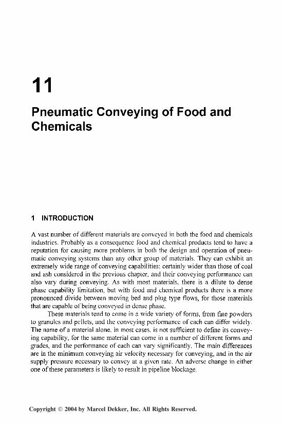
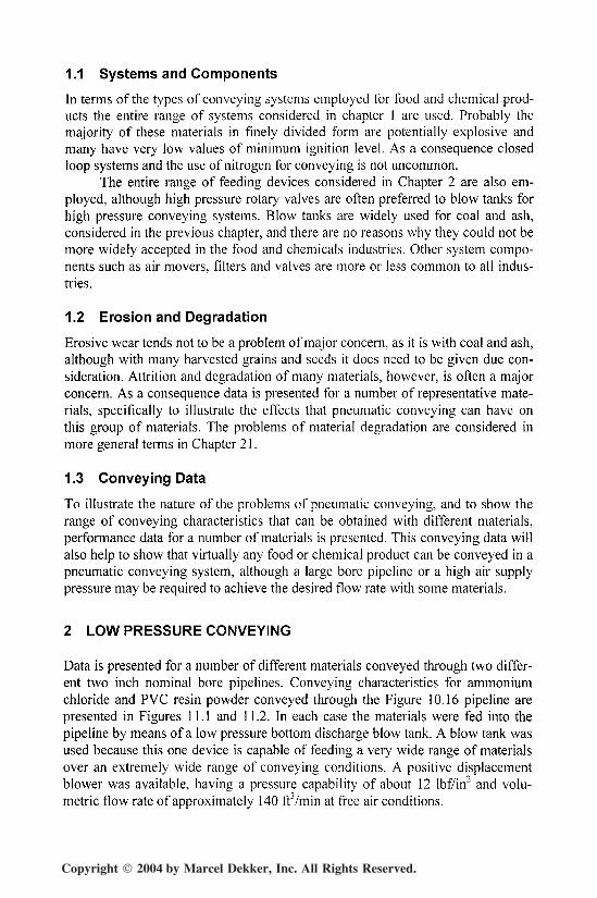
Data is presented for a number of different materials conveyed through two differ-ent two inch nominal bore pipelines. Conveying characteristics for ammoniumchloride and PVC resin powder conveyed through the Figure 10.16 pipeline arepresented in Figures 11.1 and 11.2. In each case the materials were fed into thepipeline by means of a low pressure bottom discharge blow tank. A blow tank wasused because this one device is capable of feeding a very wide range of materialsover an extremely wide range of conveying conditions. A positive displacementblower was available, having a pressure capability of about 12 lbf/in2 and volu-metric flow rate of approximately 140 fWmin at free air conditions.
Copyright 2004 by Marcel Dekker, Inc. All Rights Reserved.
Food and Chemicals 337
10
JO~ 6
1
I 2
0
Conveying LinePressure Drop - lbf/in2
Solids LoadingRatio
50 100
Free Air Flow Rate - ftVmin
150
Figure 11.1 Conveying characteristics for ammonium chloride conveyed through thepipeline shown in figure I O.I 6.
Sketches of the two pipelines were presented earlier in Figures 4.15 and10.16. These provide details of pipeline lengths and the number and geometry of
bends for reference.
10
ocSoi
|4
Conveying LinePressure Drop - lbf/in2
50 100
Free Air Flow Rate - ftVmin
Solids LoadingRatio
150
Figure 11.2 Conveying characteristics for PVC resin powder conveyed through thepipeline shown in figure 10.16.
Copyright 2004 by Marcel Dekker, Inc. All Rights Reserved.
338 Chapter 11
Conveying LinePressure Drop
- lhf/in2
Solids LoadingRatio
10
I
i6
03oi
|4'—~3
00 50 100
Free Air Flow Rate - trYmin
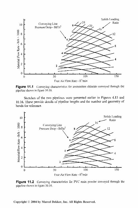
Figure 11.3 Conveying characteristics for sodium chloride (salt) conveyed through thepipeline shown in figure 4.19.
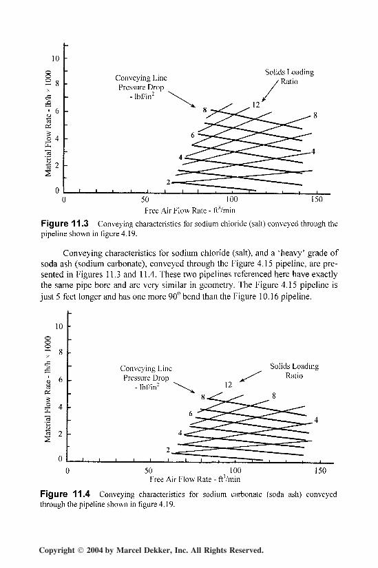
Conveying characteristics for sodium chloride (salt), and a 'heavy' grade ofsoda ash (sodium carbonate), conveyed through the Figure 4.15 pipeline, are pre-sented in Figures 11.3 and 11.4. These two pipelines referenced here have exactlythe same pipe bore and are very similar in geometry. The Figure 4.15 pipeline isjust 5 feet longer and has one more 90° bend than the Figure 10.16 pipeline.
10
Conveying LinePressure Drop
- lhf/in2
Solids LoadingRatio
12
150Free Air Flow Rate - fr/min
Figure 11.4 Conveying characteristics for sodium carbonate (soda ash) conveyedthrough the pipeline shown in figure 4.19.
Copyright 2004 by Marcel Dekker, Inc. All Rights Reserved.
Food and Chemicals 339
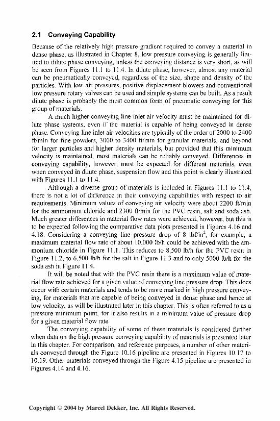
2.1 Conveying Capability
Because of the relatively high pressure gradient required to convey a material indense phase, as illustrated in Chapter 8, low pressure conveying is generally lim-ited to dilute phase conveying, unless the conveying distance is very short, as willbe seen from Figures 11.1 to 11.4. In dilute phase, however, almost any materialcan be pneumatically conveyed, regardless of the size, shape and density of theparticles. With low air pressures, positive displacement blowers and conventionallow pressure rotary valves can be used and simple systems can be built. As a resultdilute phase is probably the most common form of pneumatic conveying for thisgroup of materials.
A much higher conveying line inlet air velocity must be maintained for di-lute phase systems, even if the material is capable of being conveyed in densephase. Conveying line inlet air velocities are typically of the order of 2000 to 2400ft/min for fine powders, 3000 to 3400 ft/min for granular materials, and beyondfor larger particles and higher density materials, but provided that this minimumvelocity is maintained, most materials can be reliably conveyed. Differences inconveying capability, however, must be expected for different materials, evenwhen conveyed in dilute phase, suspension flow and this point is clearly illustratedwith Figures 11.1 to 11.4.
Although a diverse group of materials is included in Figures 11.1 to 11.4,there is not a lot of difference in their conveying capabilities with respect to airrequirements. Minimum values of conveying air velocity were about 2200 ft/minfor the ammonium chloride and 2300 ft/min for the PVC resin, salt and soda ash.Much greater differences in material flow rates were achieved, however, but this isto be expected following the comparative data plots presented in Figures 4.16 and4.18. Considering a conveying line pressure drop of 8 lbf/in2, for example, amaximum material flow rate of about 10,000 Ib/h could be achieved with the am-monium chloride in Figure 11.1. This reduces to 8,500 Ib/h for the PVC resin inFigure 11.2, to 6,500 Ib/h for the salt in Figure 11.3 and to only 5000 Ib/h for thesoda ash in Figure 11.4.
It will be noted that with the PVC resin there is a maximum value of mate-rial flow rate achieved for a given value of conveying line pressure drop. This doesoccur with certain materials and tends to be more marked in high pressure convey-ing, for materials that are capable of being conveyed in dense phase and hence atlow velocity, as will be illustrated later in this chapter. This is often referred to as apressure minimum point, for it also results in a minimum value of pressure dropfor a given material flow rate.
The conveying capability of some of these materials is considered furtherwhen data on the high pressure conveying capability of materials is presented laterin this chapter. For comparison, and reference purposes, a number of other materi-als conveyed through the Figure 10.16 pipeline are presented in Figures 10.17 to10.19. Other materials conveyed through the Figure 4.15 pipeline are presented inFigures 4.14 and 4.16.
Copyright 2004 by Marcel Dekker, Inc. All Rights Reserved.
340 Chapter 11
2.2 Material Degradation
With the sodium chloride and soda ash, presented in Figures 11.3 and 11.4, pro-grams of conveying trials were undertaken to determine the level of degradationresulting from the pneumatic conveying of these materials [1]. Both materials wereconveyed through the Figure 4.15 pipeline for this purpose. Fresh material wasloaded into the test facility, it was circulated a total of five times and samples weretaken during each run.
Guaranteeing uniformity and accuracy in the sampling of bulk particulatematerials is always a problem and it is generally recommended that samplesshould be taken from a moving stream of the bulk material. In this case sampleswere taken by means of a diverter valve that was positioned near to the end of thepipeline.
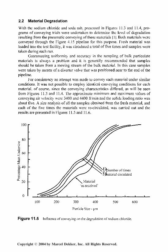
For consistency an attempt was made to convey each material under similarconditions. It was not possible to employ identical conveying conditions for eachmaterial, of course, since the conveying characteristics differed, as will be seenfrom Figures 11.3 and 11.4. The approximate minimum and maximum values ofconveying air velocity were 3400 and 4400 ft/rnin and the solids loading ratio wasabout five. A size analysis of all the samples obtained from the fresh material, andeach of the five times the materials were re-circulated, was carried out and theresults are presented in Figures 11.5 and 11.6.
100 r
80Nt/3b-a5 60Cfl
a
" 40 r // ^ x\\x i-v; Clumber of times
Sjhaterial circulated
20
100 200 300 400 500 600
Particle Size - urn
Figure 11.5 Influence of conveying on the degradation of sodium chloride.
Copyright 2004 by Marcel Dekker, Inc. All Rights Reserved.
Food and Chemicals 341
100 r
80
cD 60
a 40TO
20
0100 200 500 600300 400
Particle Size - u,m
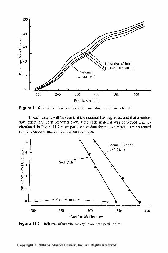
Figure 11.6 Influence of conveying on the degradation of sodium carbonate.
In each case it will be seen that the material has degraded, and that a notice-able effect has been recorded every time each material was conveyed and re-circulated. In Figure 11.7 mean particle size data for the two materials is presentedso that a direct visual comparison can be made.
Sodium Chloride'(Salt)
HU8
u.0
3
0
Soda Ash
Fresh Material
200 350250 300
Mean Particle Size - um
Figure 11.7 Influence of material conveying on mean particle size.
400
Copyright 2004 by Marcel Dekker, Inc. All Rights Reserved.
342 Chapter 11
For the salt there was an overall reduction of about 78 jum from the freshmaterial, having a mean particle size of about 388 /jm. For the soda ash there wasan overall reduction of about 68 /um from the fresh material, having a mean parti-cle size of about 343 //m.
3 HIGH PRESSURE CONVEYING
All of the preceding data in this chapter has been for the low pressure (up to 8lbf/in2), and hence dilute phase, suspension flow of the materials considered,whether they had dense phase conveying capability or not. In this section, data ispresented for materials conveyed with air pressures of up to 30 lbf/in2 gauge.
With higher pressure air, for approximately the same length of pipeline,pressure gradients are now such that dense phase conveying is a possibility, butonly for materials that are naturally capable of being conveyed at low velocity,since this is a conventional type of conveying facility.
Although the data presented is derived from a high pressure conveying facil-ity, low pressure results are also included within the overall conveying characteris-tics, and so this area is equally appropriate for low pressure conveying systems.The data is simply compressed into a small area, rather than being magnified, aswith Figures 11.1 to 11.4.
The authors have conveyed a considerable number of different materialsthrough one particular pipeline and a sketch of this was presented earlier in Figure4.2. This is also a two inch nominal bore pipeline and materials were fed into thepipeline by means of a blow tank once again, for the same reasons as outlinedabove for the low pressure conveying data. In this case it was a high pressure, topdischarge, blow tank with a pressure rating of 100 lbf/in2 gauge. The air supplycame from a reciprocating compressor capable of delivering 200 ftVmin of free airat a pressure of 100 lbf/in2 gauge.
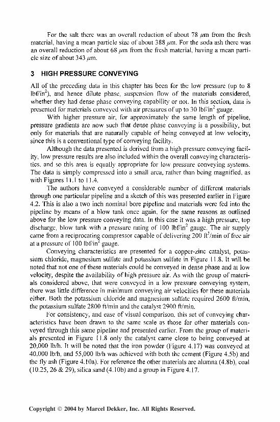
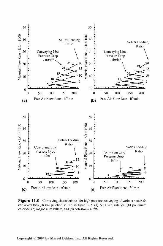
Conveying characteristics are presented for a copper-zinc catalyst, potas-sium chloride, magnesium sulfate and potassium sulfate in Figure 11.8. It will benoted that not one of these materials could be conveyed in dense phase and at lowvelocity, despite the availability of high pressure air. As with the group of materi-als considered above, that were conveyed in a low pressure conveying system,there was little difference in minimum conveying air velocities for these materialseither. Both the potassium chloride and magnesium sulfate required 2600 ft/min,the potassium sulfate 2800 ft/min and the catalyst 2900 ft/min.
For consistency, and ease of visual comparison, this set of conveying char-acteristics have been drawn to the same scale as those for other materials con-veyed through this same pipeline and presented earlier. From the group of materi-als presented in Figure 11.8 only the catalyst came close to being conveyed at20,000 Ib/h. It will be noted that the iron powder (Figure 4.17) was conveyed at40,000 Ib/h, and 55,000 Ib/h was achieved with both the cement (Figure 4.5b) andthe fly ash (Figure 4. lOa). For reference the other materials are alumna (4.8b), coal(10.25, 26 & 29), silica sand (4.1 Ob) and a group in Figure 4.17.
Copyright 2004 by Marcel Dekker, Inc. All Rights Reserved.
Food and Chemicals 343
50
2 40X
J
1 30IBOH
1 20
."s'C
3 10
: 50
oo; Solids Loading ~ 40
Ratio jl
Conveying Line \ ^ 30Pressure Drop \ 3
I - Ibf/in2 \ ^ >X 25 ^^20 o 20
^"^ tu
: 2°^<W15 31S^^^^ o_^>^-«r-10 | 10
™^~~<^^ c ^• '-^^^^^r
"
; Solids LoadingRatio
\
Conveying Line \Pressure Drop \
". - Ibf/in2 ^\ ^2°
; V ._^-15
•jn " -̂J> '''*'
.^1^^^^^10 "V .̂ * ^^^"^
: r̂ ^^S"5
0 u0 50 100 150 200 0 50 100 150 200
50
0
2 40X
1"7 30u"3ai| 20
•1I 102
Q
• 50
oo2 40XJ3iB
i Solids Loading 7 39Ratio |
[ Conveying Line \ c£Pressure Drop \ | jn
". - Ibf/in2 i ^ E
: V 30 <^ 3 |~ *• i A ^ 1 0
20j,t f^... "S
"• 12_=--^==^IT~ 5
1 I 1 1 1 1 1 1 1 1 1 1 1 1 1 n
:
•
-•; Solids LoadingI Conveying Line Ratio
Pressure Drop i• - Ibf/in2 1 1. j
' 2^_ ^- *£-̂ ^J"L.' 4" , , , , , , r-rr ,*, , i , , , , 1-1 . ,
0 50 100 150 200 0 50 100 150 200
/_» Free Air Flow Rate - ft3/min / ji Free Air Flow Rate - ft3/min
Figure 11.8 Conveying characteristics for high pressure conveying of various materialsconveyed through the pipeline shown in figure 4.2. (a) A Cu-Zn catalyst, (b) potassiumchloride, (c) magnesium sulfate, and (d) potassium sulfate.
Copyright 2004 by Marcel Dekker, Inc. All Rights Reserved.
344 Chapter 11
3.1 Conveying Capability
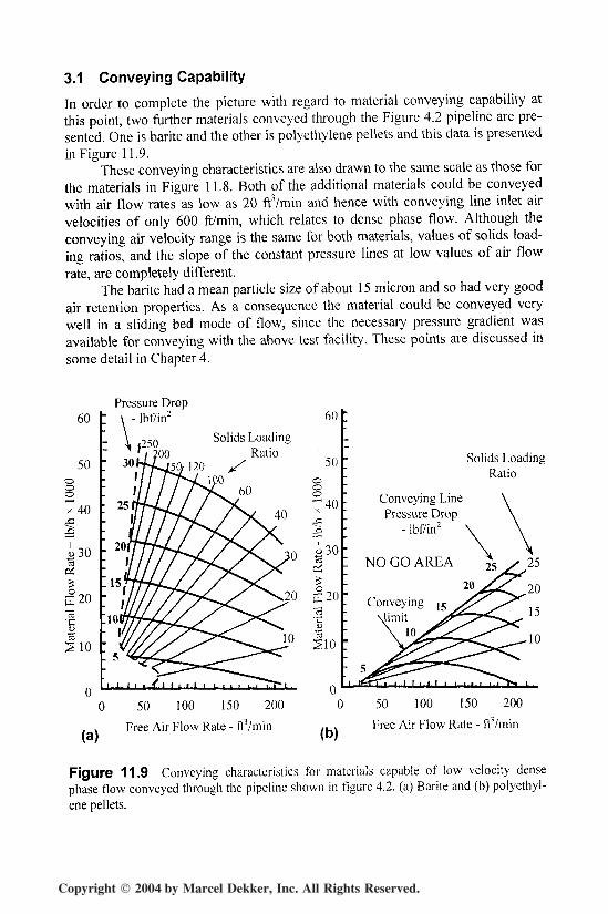
In order to complete the picture with regard to material conveying capability atthis point, two further materials conveyed through the Figure 4.2 pipeline are pre-sented. One is barite and the other is polyethylene pellets and this data is presentedin Figure 11.9.
These conveying characteristics are also drawn to the same scale as those forthe materials in Figure 11.8. Both of the additional materials could be conveyedwith air flow rates as low as 20 ftVmin and hence with conveying line inlet airvelocities of only 600 ft/min, which relates to dense phase flow. Although theconveying air velocity range is the same for both materials, values of solids load-ing ratios, and the slope of the constant pressure lines at low values of air flowrate, are completely different.
The barite had a mean particle size of about 15 micron and so had very goodair retention properties. As a consequence the material could be conveyed verywell in a sliding bed mode of flow, since the necessary pressure gradient wasavailable for conveying with the above test facility. These points are discussed insome detail in Chapter 4.
60
S10
Pressure Drop- lbf/in2
(a)
0 50 100 150 200
Free Air Flow Rate - ftVmin (b)
Solids LoadingRatio
Conveying LinePressure Drop
- lbf/in2
NO GO AREA
50 100 150 200
Free Air Flow Rate - frYmin
Figure 11.9 Conveying characteristics for materials capable of low velocity densephase flow conveyed through the pipeline shown in figure 4.2. (a) Barite and (b) polyethyl-ene pellets.
Copyright 2004 by Marcel Dekker, Inc. All Rights Reserved.
Food and Chemicals 345
The polyethylene pellets had a mean particle size of about 0-15 in (4 mm)and a particle density of about 57 Ib/fT. The main feature, however, was that theparticles were all uniform and so there was virtually no separate particle size dis-tribution. As a consequence the material had very good permeability and so wouldconvey in dense phase, at low velocity, in a conventional pneumatic conveyingsystem, in plug type flow.
The very high permeability accounts for the relatively low maximum valueof solids loading ratio achieved. Powdered materials have almost no permeability,but have very good air retention properties, and so very high values of solids load-ing ratio can be achieved, particularly if high pressure gradients are available forconveying.
Although the material will convey with air velocities down to 600 ft/min,material flow rates are low at low air flow rates. There is a marked pressure mini-mum with this type of conveying characteristic, such that below the pressureminimum a decrease in air flow rate will result in a decrease in material flow ratefor a given air supply pressure.
If particle melting, and the formation of 'angel hairs' is a problem with thistype of material, however, low velocity conveying is an option for minimizing theproblem. The conveying characteristics of this type of material are consideredfurther in a later section in this chapter.
3.2 Dilute Phase Conveying
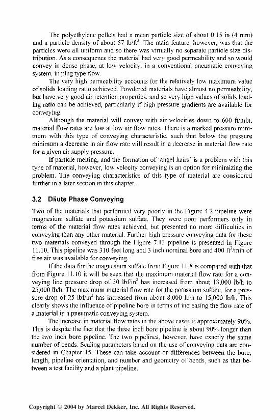
Two of the materials that performed very poorly in the Figure 4.2 pipeline weremagnesium sulfate and potassium sulfate. They were poor performers only interms of the material flow rates achieved, but presented no more difficulties inconveying than any other material. Further high pressure conveying data for thesetwo materials conveyed through the Figure 7.13 pipeline is presented in Figure11.10. This pipeline was 310 feet long and 3 inch nominal bore and 400 ft3/min offree air was available for conveying.
If the data for the magnesium sulfate from Figure 11.8 is compared with thatfrom Figure 11.10 it will be seen that the maximum material flow rate for a con-veying line pressure drop of 30 lbf/in2 has increased from about 13,000 Ib/h to25,000 Ib/h. The maximum material flow rate for the potassium sulfate, for a pres-sure drop of 25 lbf/in2 has increased from about 8,000 Ib/h to 15,000 Ib/h. Thisclearly shows the influence of pipeline bore in terms of increasing the flow rate ofa material in a pneumatic conveying system.
The increase in material flow rates in the above cases is approximately 90%.This is despite the fact that the three inch bore pipeline is about 90% longer thanthe two inch bore pipeline. The two pipelines, however, have exactly the samenumber of bends. Scaling parameters based on the use of conveying data are con-sidered in Chapter 15. These can take account of differences between the bore,length, pipeline orientation, and number and geometry of bends, such as that be-tween a test facility and a plant pipeline.
Copyright 2004 by Marcel Dekker, Inc. All Rights Reserved.
346 Chapter 11
Conveying LinePressure Drop
- lbf/in2 v
NO GO AREA
Solids Loadingp RatioLine Ratio
0 100
(a)
1UU Z.UU JUU
Free Air Flow Rate
100
5 - ftVminFree
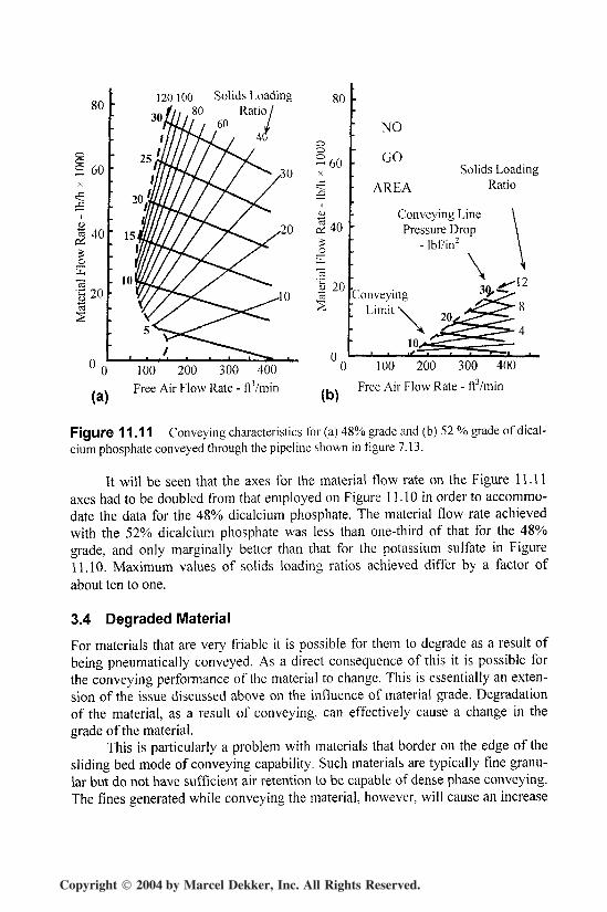
Figure 11.10 Conveying characteristics for materials conveyed through the pipelineshown in figure 7.13. (a) Magnesium sulfate and (b) potassium sulfate.
3.3 Material Grade
Great care must be exercised when a specific name is given to a material. Manymaterials are available in a variety of grades and it is quite possible for the convey-ing characteristics for different grades to be very different from one another. Aparticular case is that of pulverized fuel ash, and this was considered in some de-tail in Chapter 10. Although it is exactly the same material, the ash collected indifferent hoppers in a boiler plant will have very different particle size distribu-tions. That collected in the economizer hoppers, close to the combustion zone, willgenerally be very coarse and have no dense phase conveying capability at all. Thatcollected in the electrostatic precipitator hoppers, furthest from the combustionzone, will be a very fine powder and will convey in dense phase very well. Thedifferences in conveying capability were clearly illustrated in Figure 10.14.
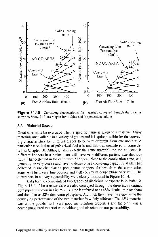
Data for the conveying of two grades of dicalcium phosphate is included inFigure 11.11. These materials were also conveyed through the three inch nominalbore pipeline shown in Figure 7.13. One is referred to as 48% dicalcium phosphateand the other as 52% dicalcium phosphate. Although they have the same name theconveying performance of the two materials is widely different. The 48% materialwas a fine powder with very good air retention properties and the 52% was acoarse granulated material with neither good air retention nor permeability.
Copyright 2004 by Marcel Dekker, Inc. All Rights Reserved.
Food and Chemicals 347
80
2 60
I 40
_o
20
0
30
120100 Solids Loading80 Ratio I
60
25
80
o0
2 60X
JD
iJ
_0
"s'£ 2003
n
•
; NO
" GOSolids Loading
• AREA Ratio
Conveying Line \Pressure Drop \
- lbf/in2 \
[ \ *^^1 -^
U-\^^'0
(a)
100 200 300 400Free Air Flow Rate - ftVmin (b)
100 200 300 400
Free Air Flow Rate - ft3/min
Figure 11.11 Conveying characteristics for (a) 48% grade and (b) 52 % grade of dical-cium phosphate conveyed through the pipeline shown in figure 7.13.
It will be seen that the axes for the material flow rate on the Figure 11.11axes had to be doubled from that employed on Figure 11.10 in order to accommo-date the data for the 48% dicalcium phosphate. The material flow rate achievedwith the 52% dicalcium phosphate was less than one-third of that for the 48%grade, and only marginally better than that for the potassium sulfate in Figure11.10. Maximum values of solids loading ratios achieved differ by a factor of
about ten to one.
3.4 Degraded Material
For materials that are very friable it is possible for them to degrade as a result ofbeing pneumatically conveyed. As a direct consequence of this it is possible forthe conveying performance of the material to change. This is essentially an exten-sion of the issue discussed above on the influence of material grade. Degradationof the material, as a result of conveying, can effectively cause a change in thegrade of the material.
This is particularly a problem with materials that border on the edge of thesliding bed mode of conveying capability. Such materials are typically fine granu-lar but do not have sufficient air retention to be capable of dense phase conveying.The fines generated while conveying the material, however, will cause an increase
Copyright 2004 by Marcel Dekker, Inc. All Rights Reserved.
348 Chapter 11
in the air retention properties of the material and this, in turn, will result in a grad-ual lowering of the minimum velocity at which the material can be conveyed.
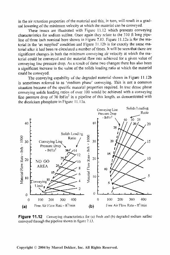
These issues are illustrated with Figure 11.12 which presents conveyingcharacteristics for sodium sulfate. Once again they relate to the 310 ft long pipe-line of three inch nominal bore shown in Figure 7.13. Figure 11.12a is for the ma-terial in the 'as supplied' condition and Figure 11.12b is for exactly the same ma-terial after it had been re-circulated a number of times. It will be seen that there aresignificant changes in both the minimum conveying air velocity at which the ma-terial could be conveyed and the material flow rate achieved for a given value ofconveying line pressure drop. As a result of these two changes there has also beena significant increase in the value of the solids loading ratio at which the materialcould be conveyed.
The conveying capability of the degraded material shown in Figure 11.12bis sometimes referred to as 'medium phase' conveying. This is not a commonsituation because of the specific material properties required. In true dense phaseconveying solids loading ratios of over 100 would be achieved with a conveyingline pressure drop of 30 lbf/in2 in a pipeline of this length, as demonstrated withthe dicalcium phosphate in Figure 11.1 la.
40
- 30X
|
u
(2 20
_0
u."sI 10
Conveying LinePressure Drop
- Ibf7in2
Solids LoadingRatio
Solids LoadingRatio /
Conveying Line /Pressure Drop \ /
-lbf/in2 30//14'12
25J""NO GO
40
2 30
ID
I 20
I 10Conveying
Limit
(a)
100 200 300 400
Free Air Flow Rate - ftVmin (b)
100 200 300 400
Free Air Flow Rate - ft3/min
Figure 11.12 Conveying characteristics for (a) fresh and (b) degraded sodium sulfateconveyed through the pipeline shown in figure 7.13.
Copyright 2004 by Marcel Dekker, Inc. All Rights Reserved.
Food and Chemicals 349
If the material were to be re-circulated and degraded further it is likely thatconveying would be possible at progressively lower velocities and higher solidsloading ratios. For materials with no dense phase conveying capability it isunlikely that they could be conveyed at a solids loading ratio much higher than 25with a conveying line pressure drop of 30 lbf/in2 in a pipeline of this length.
If dramatic changes such as these occur to a material over relatively shortconveying distances, it is generally necessary to undertake conveying trials withfresh material every time it is conveyed. If this is not done serious errors can resultif conveying characteristics such as those presented here are to be produced. Theissue of material degradation as a result of re-circulating is considered in moredetail in relation to soda ash later in this chapter.
3.5 Plastic Materials
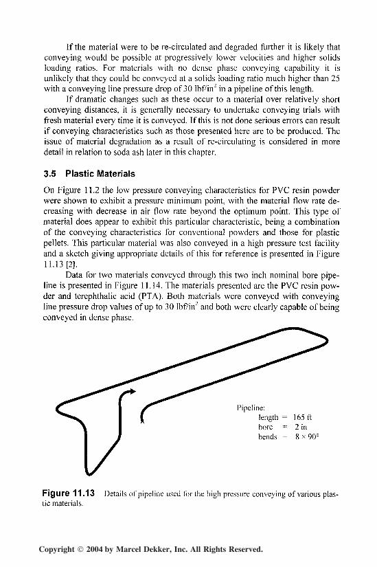
On Figure 11.2 the low pressure conveying characteristics for PVC resin powderwere shown to exhibit a pressure minimum point, with the material flow rate de-creasing with decrease in air flow rate beyond the optimum point. This type ofmaterial does appear to exhibit this particular characteristic, being a combinationof the conveying characteristics for conventional powders and those for plasticpellets. This particular material was also conveyed in a high pressure test facilityand a sketch giving appropriate details of this for reference is presented in Figure11.13 [2].
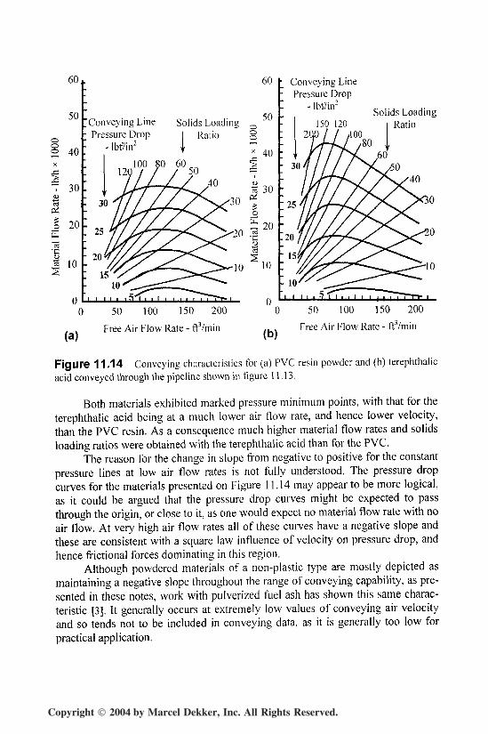
Data for two materials conveyed through this two inch nominal bore pipe-line is presented in Figure 11.14. The materials presented are the PVC resin pow-der and terephthalic acid (PTA). Both materials were conveyed with conveyingline pressure drop values of up to 30 lbf/in2 and both were clearly capable of beingconveyed in dense phase.
Pipeline:length = 165ftbore = 2 inbends = 8 * 90°
Figure 11.13 Details of pipeline used for the high pressure conveying of various plas-tic materials.
Copyright 2004 by Marcel Dekker, Inc. All Rights Reserved.
350 Chapter 11
60
50
60
Conveying LinePressure Drop
Solids LoadingRatio
50ooo
1 Conveying LinePressure Drop
- Ibf/in2
Solids LoadingRatio
(a)Free Air Flow Rate - ft/min (b)
50 100 150 200
Free Air Flow Rate - ftVmin
Figure 11.14 Conveying characteristics for (a) PVC resin powder and (b) terephthalicacid conveyed through the pipeline shown in figure 11.13.
Both materials exhibited marked pressure minimum points, with that for theterephthalic acid being at a much lower air flow rate, and hence lower velocity,than the PVC resin. As a consequence much higher material flow rates and solidsloading ratios were obtained with the terephthalic acid than for the PVC.
The reason for the change in slope from negative to positive for the constantpressure lines at low air flow rates is not fully understood. The pressure dropcurves for the materials presented on Figure 11.14 may appear to be more logical,as it could be argued that the pressure drop curves might be expected to passthrough the origin, or close to it, as one would expect no material flow rate with noair flow. At very high air flow rates all of these curves have a negative slope andthese are consistent with a square law influence of velocity on pressure drop, andhence factional forces dominating in this region.
Although powdered materials of a non-plastic type are mostly depicted asmaintaining a negative slope throughout the range of conveying capability, as pre-sented in these notes, work with pulverized fuel ash has shown this same charac-teristic [3]. It generally occurs at extremely low values of conveying air velocityand so tends not to be included in conveying data, as it is generally too low forpractical application.
Copyright 2004 by Marcel Dekker, Inc. All Rights Reserved.
Food and Chemicals 351
The pipeline shown in Figure 11.13 is very similar in terms of distance andgeometry to that of the Figure 4.2 pipeline and so the data for the materials pre-sented in Figure 11.12 can be compared reasonably well with that for the materialsshown in Figures 11.8 and 11.9.
It will be seen that the material flow rates obtained with both the PVC resinand the terephthalic acid were much higher than any of the materials presented inFigure 11.8. This is due, in part to the fact that the plastic materials could be con-veyed in dense phase, and hence at very much lower air flow rates. In comparisonwith the barite in Figure 11.9, however, material flow rates were significantlylower.
3.6 Pelletized Materials
Conveying characteristics for polyethylene pellets were presented earlier in Figure11.9. These were derived for flow through a two inch nominal bore pipeline. Inanalyzing the conveying data to produce the conveying characteristics it wasfound that the lines of constant conveying line pressure drop gradually mergedtogether as the air flow rate reduced and it was felt that this was a function of therelatively small bore pipeline employed.
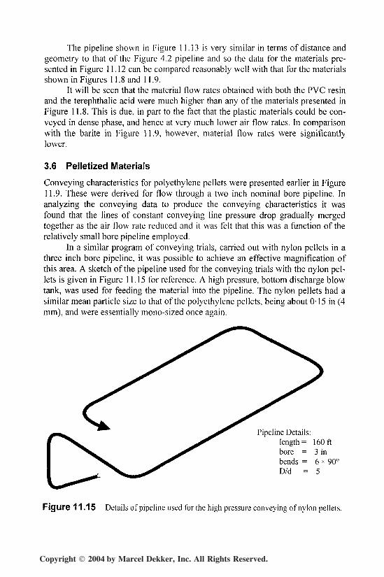
In a similar program of conveying trials, carried out with nylon pellets in athree inch bore pipeline, it was possible to achieve an effective magnification ofthis area. A sketch of the pipeline used for the conveying trials with the nylon pel-lets is given in Figure 11.15 for reference. A high pressure, bottom discharge blowtank, was used for feeding the material into the pipeline. The nylon pellets had asimilar mean particle size to that of the polyethylene pellets, being about 0-15 in (4mm), and were essentially mono-sized once again.
Pipeline Details:length = 160ftbore = 3 inbends = 6 * 90°D/d = 5
Figure 11.15 Details of pipeline used for the high pressure conveying of nylon pellets.
Copyright 2004 by Marcel Dekker, Inc. All Rights Reserved.
352 Chapter 11
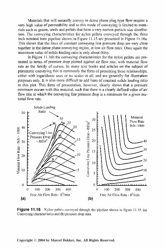
Materials that will naturally convey in dense phase plug type flow require avery high value of permeability and so this mode of conveying is limited to mate-rials such as grains, seeds and pellets that have a very narrow particle size distribu-tion. The conveying characteristics for nylon pellets conveyed through the threeinch nominal bore pipeline shown in Figure 11.15 are presented in Figure 11.16a.This shows that the lines of constant conveying line pressure drop are very closetogether in the dense phase conveying region, at low air flow rates. Once again themaximum value of solids loading ratio is only about thirty.
In Figure 11.16b the conveying characteristics for the nylon pellets are pre-sented in terms of pressure drop plotted against air flow rate, with material flowrate as the family of curves. In many text books and articles on the subject ofpneumatic conveying this is commonly the form of presenting these relationships,either with logarithmic axes or no scales at all, and are generally for illustrationpurposes only. It is also more difficult to add lines of constant solids loading ratioto this plot. This form of presentation, however, clearly shows that a pressureminimum occurs with this material, such that there is a clearly defined value of airflow rate at which the conveying line pressure drop is a minimum for a given ma-terial flow rate.
Solids Loading
50 h Ratio \
40
30
20
10
,30
-Conveying LinePressure Drop
- Ibf7in2
(a)
0 100 200 300 400
Free Air Flow Rate - ft3/min
30
~ 25
20
15
CJc
co0
10
MaterialFlow RateIb/hxlOOO
40
(b)
0 100 200 300 400
Free Air Flow Rate - fr'/min
Figure 11.16 Nylon pellets conveyed through the pipeline shown in figure 11.15. (a)Conveying characteristics and (b) pressure drop data.
Copyright 2004 by Marcel Dekker, Inc. All Rights Reserved.
Food and Chemicals 353
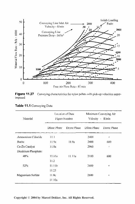
From Figure 11.16a it will be seen that the pressure minimum point occursat a gradually reducing value of air flow rate as the value of conveying line pres-sure drop decreases. This pressure minimum point does, in fact, occur at a convey-ing line inlet air velocity of approximately 2600 ft/min over the entire range ofpressures investigated. Above this velocity the conveying characteristics are verysimilar to those of any other material conveyed in dilute phase, suspension flow.2600 ft/min is approximately the minimum value of conveying air velocity for thedilute phase conveying of this material. This point is considered further later inthis chapter.
The material, however, is clearly capable of being conveyed at much lowervelocities than 2600 ft/min and it is also clear that at the pressure minimum pointthe mode of flow starts to change to one of plug flow, with reduction in air flowrate. Some materials have a smooth transition from dilute to dense phase flow withreduction in air flow rate, some show very erratic and unreliable behavior in thisregion, and others have a band of velocity values across which they cannot beconveyed, but when the velocity reduces to about 1000 or 1200 ft/min most mate-rials of this type will be capable of dense phase plug type flow in a conventionalconveying system.
3.7 Soda Ash
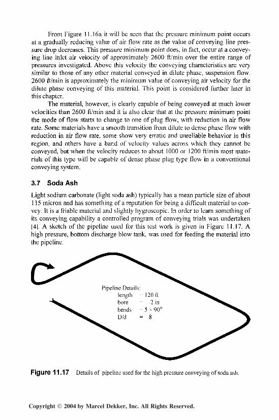
Light sodium carbonate (light soda ash) typically has a mean particle size of about115 micron and has something of a reputation for being a difficult material to con-vey. It is a friable material and slightly hygroscopic. In order to learn something ofits conveying capability a controlled program of conveying trials was undertaken[4]. A sketch of the pipeline used for this test work is given in Figure 11.17. Ahigh pressure, bottom discharge blow tank, was used for feeding the material intothe pipeline.
Pipeline Details:length =120 ft
Figure 11.17 Details of pipeline used for the high pressure convey ing of soda ash.
Copyright 2004 by Marcel Dekker, Inc. All Rights Reserved.
354 Chapter 11
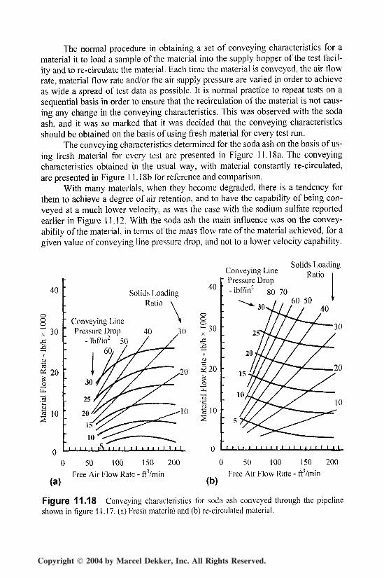
The normal procedure in obtaining a set of conveying characteristics for amaterial it to load a sample of the material into the supply hopper of the test facil-ity and to re-circulate the material. Each time the material is conveyed, the air flowrate, material flow rate and/or the air supply pressure are varied in order to achieveas wide a spread of test data as possible. It is normal practice to repeat tests on asequential basis in order to ensure that the recirculation of the material is not caus-ing any change in the conveying characteristics. This was observed with the sodaash, and it was so marked that it was decided that the conveying characteristicsshould be obtained on the basis of using fresh material for every test run.
The conveying characteristics determined for the soda ash on the basis of us-ing fresh material for every test are presented in Figure 11.18a. The conveyingcharacteristics obtained in the usual way, with material constantly re-circulated,are presented in Figure 11.18b for reference and comparison.
With many materials, when they become degraded, there is a tendency forthem to achieve a degree of air retention, and to have the capability of being con-veyed at a much lower velocity, as was the case with the sodium sulfate reportedearlier in Figure 11.12. With the soda ash the main influence was on the convey-ability of the material, in terms of the mass flow rate of the material achieved, for agiven value of conveying line pressure drop, and not to a lower velocity capability.
Solids LoadingRatio
40
Solids LoadingConveying Line Ratjo
Pressure Drop
30
(a)
0 50 100 150 200Free Air Flow Rate - ftVmin
(b)
0 50 100 150 200Free Air Flow Rate - ft3/min
Figure 11.18 Conveying characteristics for soda ash conveyed through the pipelineshown in figure 11.17. (a) Fresh material and (b) re-circulated material.
Copyright 2004 by Marcel Dekker, Inc. All Rights Reserved.
Food and Chemicals 355
As will be seen from Figure 11.18a, the fresh material had a degree of densephase conveying capability since it could be conveyed at solids loading ratios ofup to about 60. Although higher values of solids loading ratio were achieved withthe degraded material this was due to the fact that higher material flow rates wereachieved. The fresh material showed a marked pressure minimum point in theconveying characteristics, whereas the degraded material showed no change inslope of the constant conveying line pressure drop curves with reduction in airflow rate.
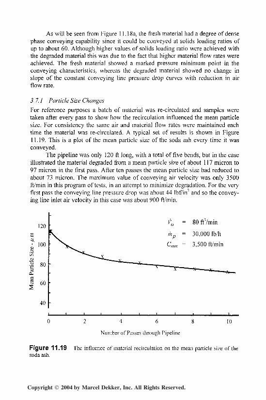
3.7.1 Particle Size Changes
For reference purposes a batch of material was re-circulated and samples weretaken after every pass to show how the recirculation influenced the mean particlesize. For consistency the same air and material flow rates were maintained eachtime the material was re-circulated. A typical set of results is shown in Figure11.19. This is a plot of the mean particle size of the soda ash every time it wasconveyed.
The pipeline was only 120 ft long, with a total of five bends, but in the caseillustrated the material degraded from a mean particle size of about 117 micron to97 micron in the first pass. After ten passes the mean particle size had reduced toabout 73 micron. The maximum value of conveying air velocity was only 3500ft/min in this program of tests, in an attempt to minimize degradation. For the veryfirst pass the conveying line pressure drop was about 44 Ibf/in" and so the convey-ing line inlet air velocity in this case was about 900 ft/min.
120E
I'00
1 8°<X
I 6°
40
V0 = 80 frVmin
mp = 30,000 Ib/h
Cmax = 3,500 ft/min
4 6 8
Number of Passes through Pipeline
10
Figure 11.19 The influence of material recirculation on the mean particle size of thesoda ash.
Copyright 2004 by Marcel Dekker, Inc. All Rights Reserved.
356 Chapter 11
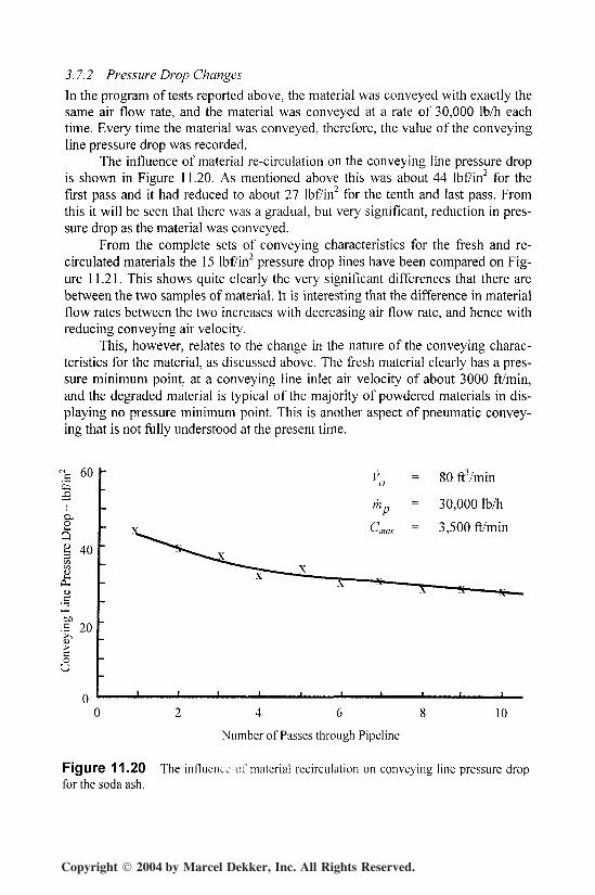
3.7.2 Pressure Drop Changes
In the program of tests reported above, the material was conveyed with exactly thesame air flow rate, and the material was conveyed at a rate of 30,000 Ib/h eachtime. Every time the material was conveyed, therefore, the value of the conveyingline pressure drop was recorded.
The influence of material re-circulation on the conveying line pressure dropis shown in Figure 11.20. As mentioned above this was about 44 lbf/in2 for thefirst pass and it had reduced to about 27 lbf/in2 for the tenth and last pass. Fromthis it will be seen that there was a gradual, but very significant, reduction in pres-sure drop as the material was conveyed.
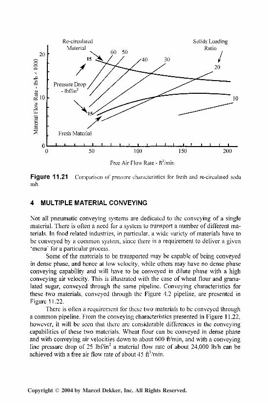
From the complete sets of conveying characteristics for the fresh and re-circulated materials the 15 lbf/in2 pressure drop lines have been compared on Fig-ure 11.21. This shows quite clearly the very significant differences that there arebetween the two samples of material. It is interesting that the difference in materialflow rates between the two increases with decreasing air flow rate, and hence withreducing conveying air velocity.
This, however, relates to the change in the nature of the conveying charac-teristics for the material, as discussed above. The fresh material clearly has a pres-sure minimum point, at a conveying line inlet air velocity of about 3000 ft/min,and the degraded material is typical of the majority of powdered materials in dis-playing no pressure minimum point. This is another aspect of pneumatic convey-ing that is not fully understood at the present time.
c 60„
m = 30,000 Ib/h
Qg 40
00.S 20
CoU
= 80 fr/min
P= 3,500 ft/min
0 2 4 6 8 1 0
Number of Passes through Pipeline
Figure 11.20 The influence of material recirculation on conveying line pressure dropfor the soda ash.
Copyright 2004 by Marcel Dekker, Inc. All Rights Reserved.
Food and Chemicals 357
20ooo
110
_ou.
Re-circulatedMaterial
60 50
Solids LoadingRatio
15
/Pressure Drop
- lbf/in2
Fresh Material
I I I I I I I I
50 100 150
Free Air Flow Rate - ftVmin
200
Figure 11.21 Comparison of pressure characteristics for fresh and re-circulated sodaash.
4 MULTIPLE MATERIAL CONVEYING
Not all pneumatic conveying systems are dedicated to the conveying of a singlematerial. There is often a need for a system to transport a number of different ma-terials. In food related industries, in particular, a wide variety of materials have tobe conveyed by a common system, since there is a requirement to deliver a given'menu' for a particular process.
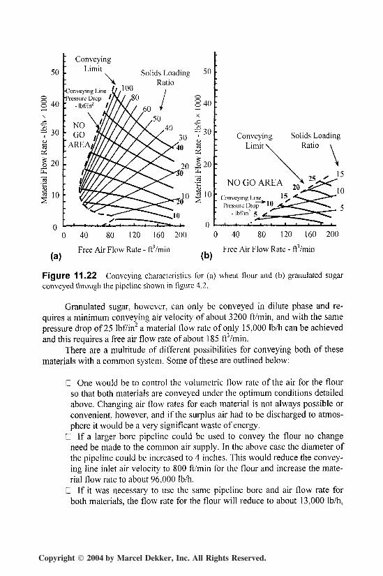
Some of the materials to be transported may be capable of being conveyedin dense phase, and hence at low velocity, while others may have no dense phaseconveying capability and will have to be conveyed in dilute phase with a highconveying air velocity. This is illustrated with the case of wheat flour and granu-lated sugar, conveyed through the same pipeline. Conveying characteristics forthese two materials, conveyed through the Figure 4.2 pipeline, are presented inFigure 11.22.
There is often a requirement for these two materials to be conveyed througha common pipeline. From the conveying characteristics presented in Figure 11.22,however, it will be seen that there are considerable differences in the conveyingcapabilities of these two materials. Wheat flour can be conveyed in dense phaseand with conveying air velocities down to about 600 ft/min, and with a conveyingline pressure drop of 25 lbf/in2 a material flow rate of about 24,000 Ib/h can beachieved with a free air flow rate of about 45 ftVmin.
Copyright 2004 by Marcel Dekker, Inc. All Rights Reserved.
358 Chapter 11
50
40
- 30
I 20tu
10
ConveyingLimit , Solids Loading
i inn RatioConveying Line {//Pressure Drop VX/ ,80
- lbf/in2
50
ConveyingLimit
NO GO AREA
Solids LoadingRatio
Conveying LinePressure Drop '0
- lbf/in2 5
160 200
(a)Free Air Flow Rate - ft/min
(b)
0 40 80 120 160 200
Free Air Flow Rate - ftVmin
Figure 11.22 Conveying characteristics for (a) wheat flour and (b) granulated sugarconveyed through the pipeline shown in figure 4.2.
Granulated sugar, however, can only be conveyed in dilute phase and re-quires a minimum conveying air velocity of about 3200 ft/min, and with the samepressure drop of 25 lbf/in2 a material flow rate of only 15,000 Ib/h can be achievedand this requires a free air flow rate of about 185 ff/min.
There are a multitude of different possibilities for conveying both of thesematerials with a common system. Some of these are outlined below:
D One would be to control the volumetric flow rate of the air for the flourso that both materials are conveyed under the optimum conditions detailedabove. Changing air flow rates for each material is not always possible orconvenient, however, and if the surplus air had to be discharged to atmos-phere it would be a very significant waste of energy.
D If a larger bore pipeline could be used to convey the flour no changeneed be made to the common air supply. In the above case the diameter ofthe pipeline could be increased to 4 inches. This would reduce the convey-ing line inlet air velocity to 800 ft/min for the flour and increase the mate-rial flow rate to about 96,000 Ib/h.
0 If it was necessary to use the same pipeline bore and air flow rate forboth materials, the flow rate for the flour will reduce to about 13,000 Ib/h,
Copyright 2004 by Marcel Dekker, Inc. All Rights Reserved.
Food and Chemicals 359
as will be seen from Figure 11.22a, which is less than that for the sugar,and is clearly a very inefficient option.
D If an air flow rate of 45 ftVmin was to be used for both materials 24,000Ib/h of flour would be conveyed, but as will be seen from Figure 11.22b,there would be no possibility of conveying any sugar. Only if the diameterof the pipeline for the sugar was reduced to one inch would it be possibleto convey the sugar with 45 ftVmin at 25 psig, but the material flow ratewould be reduced to about 3,000 Ib/h, which is unlikely to be acceptable.
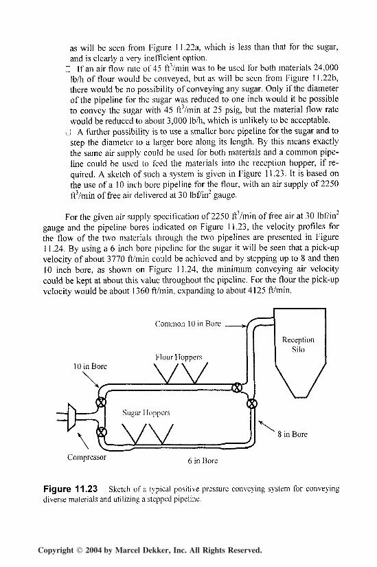
D A further possibility is to use a smaller bore pipeline for the sugar and tostep the diameter to a larger bore along its length. By this means exactlythe same air supply could be used for both materials and a common pipe-line could be used to feed the materials into the reception hopper, if re-quired. A sketch of such a system is given in Figure 11.23. It is based onthe use of a 10 inch bore pipeline for the flour, with an air supply of 2250ftVmin of free air delivered at 30 lbf/in2 gauge.
For the given air supply specification of 2250 fVVmin of free air at 30 lbf/in2
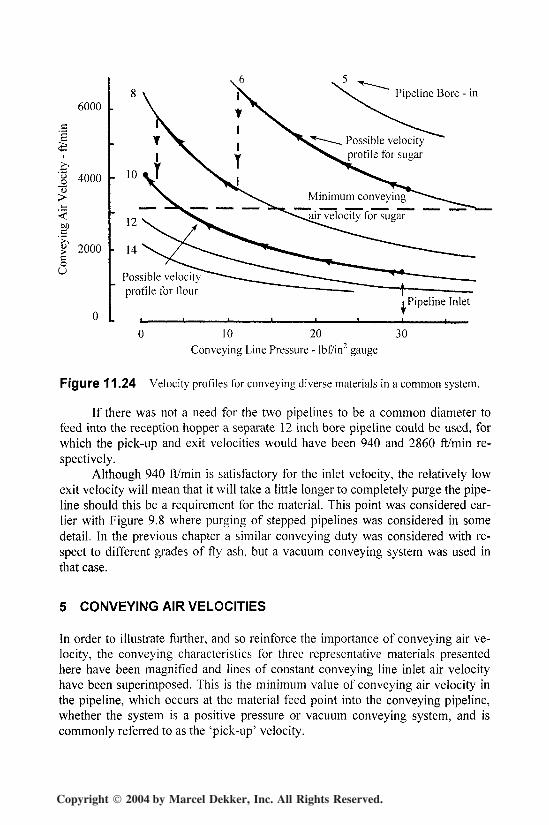
gauge and the pipeline bores indicated on Figure 11.23, the velocity profiles forthe flow of the two materials through the two pipelines are presented in Figure11.24. By using a 6 inch bore pipeline for the sugar it will be seen that a pick-upvelocity of about 3770 ft/min could be achieved and by stepping up to 8 and then10 inch bore, as shown on Figure 11.24, the minimum conveying air velocitycould be kept at about this value throughout the pipeline. For the flour the pick-upvelocity would be about 1360 ft/min, expanding to about 4125 ft/min.
10 in Bore
Common 10 in Bore
Flour HoppersvvReception
Silo
8 in Bore
Compressor 6 in Bore
Figure 11.23 Sketch of a typical positive pressure conveying system for conveyingdiverse materials and utilizing a stepped pipeline.
Copyright 2004 by Marcel Dekker, Inc. All Rights Reserved.
360 Chapter 11
_o"u
6000
4000
00c
2000coU
Pipeline Bore - in
Minimum conveying
air velocity for sugar
Possible velocityprofile for flour
line Inlet
0 10 20 30
Conveying Line Pressure - lbf/in2 gauge
Figure 11.24 Velocity profiles for conveying diverse materials in a common system.
If there was not a need for the two pipelines to be a common diameter tofeed into the reception hopper a separate 12 inch bore pipeline could be used, forwhich the pick-up and exit velocities would have been 940 and 2860 ft/min re-spectively.
Although 940 ft/min is satisfactory for the inlet velocity, the relatively lowexit velocity will mean that it will take a little longer to completely purge the pipe-line should this be a requirement for the material. This point was considered ear-lier with Figure 9.8 where purging of stepped pipelines was considered in somedetail. In the previous chapter a similar conveying duty was considered with re-spect to different grades of fly ash, but a vacuum conveying system was used inthat case.
5 CONVEYING AIR VELOCITIES
In order to illustrate further, and so reinforce the importance of conveying air ve-locity, the conveying characteristics for three representative materials presentedhere have been magnified and lines of constant conveying line inlet air velocityhave been superimposed. This is the minimum value of conveying air velocity inthe pipeline, which occurs at the material feed point into the conveying pipeline,whether the system is a positive pressure or vacuum conveying system, and iscommonly referred to as the 'pick-up' velocity.
Copyright 2004 by Marcel Dekker, Inc. All Rights Reserved.
Food and Chemicals 361
30 Conveying Line Inlet AirVelocity - ft/min
Solids Loadingj. Ratio
7 20Conveying Line
Pressure Drop - lbf/in2
1 10<D
I
00 100 200 300 400
Free Air Flow Rate - ftVmin
Figure 11.25 Conveying characteristics for 52% dicalcium phosphate with pick-upvelocities superimposed.
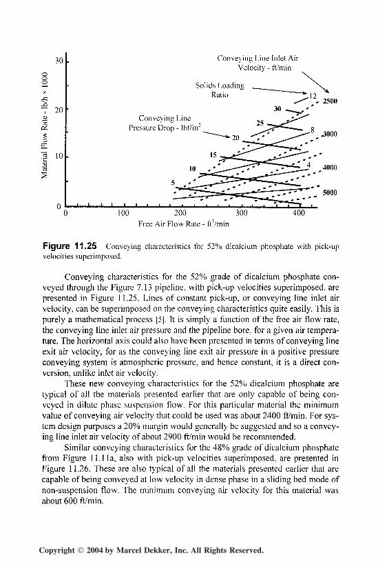
Conveying characteristics for the 52% grade of dicalcium phosphate con-veyed through the Figure 7.13 pipeline, with pick-up velocities superimposed, arepresented in Figure 11.25. Lines of constant pick-up, or conveying line inlet airvelocity, can be superimposed on the conveying characteristics quite easily. This ispurely a mathematical process [5J. It is simply a function of the free air flow rate,the conveying line inlet air pressure and the pipeline bore, for a given air tempera-ture. The horizontal axis could also have been presented in terms of conveying lineexit air velocity, for as the conveying line exit air pressure in a positive pressureconveying system is atmospheric pressure, and hence constant, it is a direct con-version, unlike inlet air velocity.
These new conveying characteristics for the 52% dicalcium phosphate aretypical of all the materials presented earlier that are only capable of being con-veyed in dilute phase suspension flow. For this particular material the minimumvalue of conveying air velocity that could be used was about 2400 ft/min. For sys-tem design purposes a 20% margin would generally be suggested and so a convey-ing line inlet air velocity of about 2900 ft/min would be recommended.
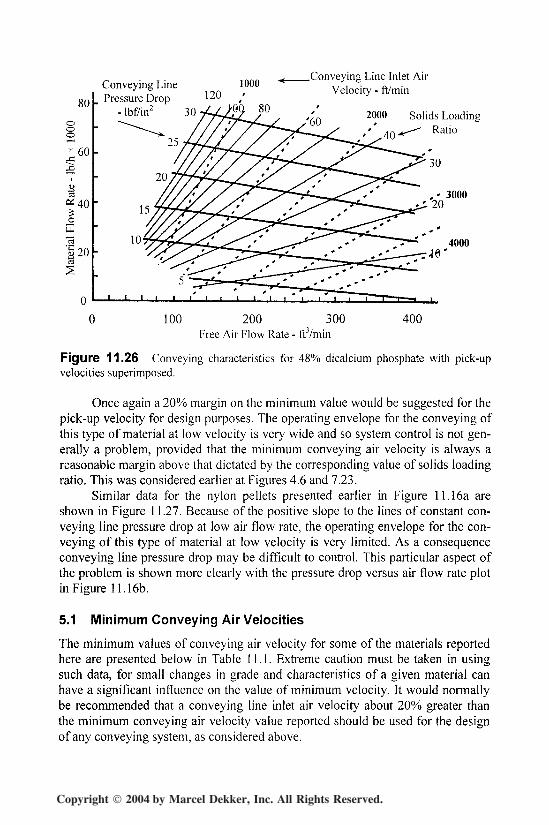
Similar conveying characteristics for the 48% grade of dicalcium phosphatefrom Figure 11.11 a, also with pick-up velocities superimposed, are presented inFigure 11.26. These are also typical of all the materials presented earlier that arecapable of being conveyed at low velocity in dense phase in a sliding bed mode ofnon-suspension flow. The minimum conveying air velocity for this material wasabout 600 ft/min.
Copyright 2004 by Marcel Dekker, Inc. All Rights Reserved.
362 Chapter 11
,„„„ ^ Conveying Line Inlet AirConveying Line 1000 Velocity - ft/min
gQ i Pressure Drop 'zu
" 2000 Solids LoadingRatio
~25////// X' ^* ^^w~x 60
I
0
a 20I
0
100 200 300 400Free Air Flow Rate - ft'/min
Figure 11.26 Conveying characteristics for 48% dicalcium phosphate with pick-upvelocities superimposed.
Once again a 20% margin on the minimum value would be suggested for thepick-up velocity for design purposes. The operating envelope for the conveying ofthis type of material at low velocity is very wide and so system control is not gen-erally a problem, provided that the minimum conveying air velocity is always areasonable margin above that dictated by the corresponding value of solids loadingratio. This was considered earlier at Figures 4.6 and 7.23.
Similar data for the nylon pellets presented earlier in Figure 11.16a areshown in Figure 1 1.27. Because of the positive slope to the lines of constant con-veying line pressure drop at low air flow rate, the operating envelope for the con-veying of this type of material at low velocity is very limited. As a consequenceconveying line pressure drop may be difficult to control. This particular aspect ofthe problem is shown more clearly with the pressure drop versus air flow rate plotin Figure 11.16b.
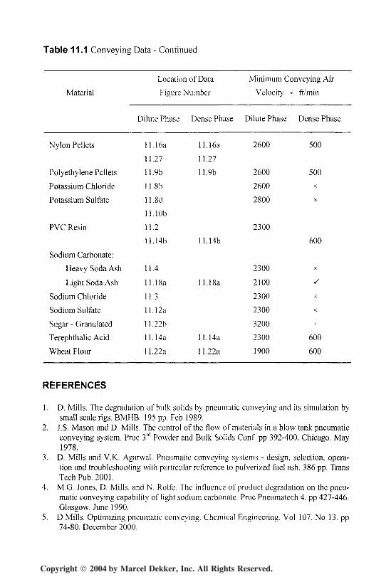
5.1 Minimum Conveying Air Velocities
The minimum values of conveying air velocity for some of the materials reportedhere are presented below in Table I l . l . Extreme caution must be taken in usingsuch data, for small changes in grade and characteristics of a given material canhave a significant influence on the value of minimum velocity. It would normallybe recommended that a conveying line inlet air velocity about 20% greater thanthe minimum conveying air velocity value reported should be used for the designof any conveying system, as considered above.
Copyright 2004 by Marcel Dekker, Inc. All Rights Reserved.
Food and Chemicals 363
50
o2 40X
^ 30<u"cdOS5.2 20
"2
13S 10
Conveying Line Inlet AirVelocity - ft/min
Conveying Line ^Pressure Drop - lbf/in2
Solids LoadingRatio
1000
I I I
100 200 300Free Air Flow Rate - ftVmin
400
Figure 11.27 Conveying characteristics for nylon pellets with pick-up velocities super-imposed.
Table 11.1 Conveying Data
Material
Ammonium Chloride
Barite
Cu-Zn Catalyst
Dicalcium Phosphate:
48%
52%
Magnesium Sulfate
Location of Data
Figure Number
Dilute Phase Dense Phase
I I . I
11. 9a 11.9a
11. 8a
l l . l l a l l . l l a
11.2
11. l i b
11.25
11. 8c
l l . l O a
Minimum Conveying Air
Velocity -
Dilute Phase
2400
2400
2900
2100
2400
2600
ft/min
Dense Phase
X
600
X
600
x
x
Copyright 2004 by Marcel Dekker, Inc. All Rights Reserved.
364 Chapter 11
Table 11.1 Conveying Data - Continued
Material
Location of Data
Figure Number
Minimum Conveying Air
Velocity - ft/min
Dilute Phase Dense Phase Dilute Phase Dense Phase
Nylon Pellets
Polyethylene Pellets
Potassium Chloride
Potassium Sulfate
PVC Resin
Sodium Carbonate:
Heavy Soda Ash
Light Soda Ash
Sodium Chloride
Sodium Sulfate
Sugar - Granulated
Terephthalic Acid
Wheat Flour
11.16a 11.16a
11.27 11.27
11. 9b 11. 9b
11. 8b
11. 8d
l l . l O b
11.2
11.14b ll.Hb
11.4
11.18a 11.18a
11.3
11.12a
11.22b
11.14a 11.14a
11.22a 11.22a
2600
2600
2600
2800
2300
2300
2100
2300
2300
3200
2300
1900
500
500X
X
600
X
/
X
x
X
600
600
REFERENCES
1. D. Mills. The degradation of bulk solids by pneumatic conveying and its simulation bysmall scale rigs. BMHB. 195 pp. Feb 1989.
2. J.S. Mason and D. Mills. The control of the flow of materials in a blow tank pneumaticconveying system. Proc 3rd Powder and Bulk Solids Conf. pp 392-400. Chicago. May1978.
3. D. Mills and V.K.. Agarwal. Pneumatic conveying systems - design, selection, opera-tion and troubleshooting with particular reference to pulverized fuel ash. 386 pp. TransTech Pub. 2001.
4. M.G. Jones, D. Mills, and N. Rolfe. The influence of product degradation on the pneu-matic conveying capability of light sodium carbonate. Proc Pneumatech 4. pp 427-446.Glasgow. June 1990.
5. D Mills. Optimizing pneumatic conveying. Chemical Engineering. Vol 107. No 13. pp74-80. December 2000.
Copyright 2004 by Marcel Dekker, Inc. All Rights Reserved.