Embed Size (px)
Citation preview

PHOTOGRAPHS
WRITTEN HISTORICAL AND DESCRIPTIVE DATA
HABS GU-2HABS GU-2
ANDERSEN AIR FORCE BASE, BUILDING 21000North Field, Anderson Air Force BaseYigoGuam
HISTORIC AMERICAN BUILDINGS SURVEYNational Park Service
U.S. Department of the Interior1849 C Street NW
Washington, DC 20240-0001

HISTORIC AMERICAN BUILDINGS SURVEY
ANDERSEN AIR FORCE BASE, BUILDING 21000 HABS No. GU-2 Location: Building 21000 is located at North Field, Andersen Air Force Base, about four
miles northeast of the town of Yigo, Guam County, in northeastern Guam, Marianas Islands. Situated in the eastern portion of the military installation, North Field contains the main cantonment and airfield of Andersen Air Force Base. Building 21000 occupies an entire rectangular-shaped block bounded by Kenny Avenue on the north, Crumm Avenue on the east, Bonis Boulevard on the south, and Twining Avenue on the west. The location is depicted on the Pati Point 7.5-minute U.S. Geological Survey (USGS) quadrangle.1 The building’s midpoint is 276,666.679 W, 1,501,667.879 N, Zone 55, Universal Transverse Mercator (UTM). The building rests on a slight rise approximately 559’ above mean sea level west of the installation golf course with a clear view of the Pacific Ocean to the east.
Present Owner/ Occupied by the 36th Wing, Pacific Air Forces, Thirteenth Air Force as host unit; Occupant: owned by Joint Region Marianas, U.S. Navy. Present Use: Building 21000 is used by the U.S. Air Force for a variety of Andersen Air Force
Base administrative uses, including credit union, base library, Base Historian’s office, and family and educational support services. Smaller portions of the building are used for contingency lodging.
Significance: Building 21000 is significant as one of the earliest post-World War II permanent
buildings at Andersen Air Force Base, Guam, and thereby played an important role in the base’s transition to a permanent Cold War forward Pacific installation. Designed in 1947 and completed in 1948, Building 21000 served as the installation’s enlisted men’s barracks. By 1957, portions of the building were used for administrative functions by the 3rd Air Division, Strategic Air Command even while continuing to serve as enlisted men’s barracks.2 Architecturally, the building is significant for demonstrating typical permanent postwar Pacific military architectural construction in its use of concrete, and its long and low massing, precast reinforced concrete slab construction, and flat roof.
Historian: Marjorie Nowick, HDR|e²M, August 2008 and September 2009. Project Information: This research and documentation project was conducted by HDR|e²M for
Andersen Air Force Base. Marjorie Nowick, M.S. and M.Phil., HDR|e²M, was
1 U.S. Geological Survey, Topographic Map of Guam, Mariana Islands, 7.5-minute Series (Reston, VA: U.S. Geological Survey, 1978). 2 Building 21000 is known from architectural drawings to have been used for the offices of the Commander and Vice-Commander by 1957. The host unit for Andersen Air Force Base during that time was the 3rd Air Division, Strategic Air Command. That Building 21000 gradually came to include the offices of the protocol officer, police, and court room lends credence to it being the administrative complex for the host unit, the 3rd Air Division. However, no specific corroborating information has been found confirming that it housed the offices of the Commander and Vice-Commander of the host unit.
ANDERSEN AIR FORCE BASE, BUILDING 21000 HABS No. GU-2
(Page 2)
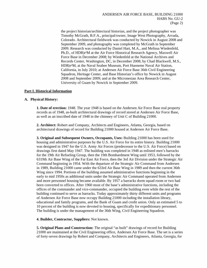
the project historian/architectural historian, and the project photographer was Timothy McGrath, B.F.A., principal/owner, Image West Photography, Arvada, Colorado. Architectural fieldwork was conducted by Nowick in August 2008 and September 2009, and photography was completed by McGrath in September 2009. Research was conducted by Daniel Hart, M.A., and Melissa Wiedenfeld, Ph.D., of HDR|e²M at the Air Force Historical Research Agency, Maxwell Air Force Base in December 2008; by Wiedenfeld at the National Archives and Records Center, Washington, DC, in December 2008; by Chad Blackwell, M.S., HDR|e²M, at the Naval Seabee Museum, Port Hueneme Naval Air Station, California, in July 2010; at Andersen Air Force Base 36th Civil Engineering Squadron, Heritage Center, and Base Historian’s office by Nowick in August 2008 and September 2009; and at the Micronesian Area Research Center, University of Guam by Nowick in September 2009.
Part I. Historical Information A. Physical History:
1. Date of erection: 1948. The year 1948 is based on the Andersen Air Force Base real property records as of 1948, as-built architectural drawings of record stored at Andersen Air Force Base, as well as an inscribed date of 1948 in the chimney of Unit C of Building 21000.
2. Architect: Robert and Company, Architects and Engineers, Atlanta, Georgia, based on architectural drawings of record for Building 21000 housed at Andersen Air Force Base.
3. Original and Subsequent Owners, Occupants, Uses: Building 21000 has been used for housing and administrative purposes by the U.S. Air Force for its entire history. Building 21000 was designed in 1947 for the U.S. Army Air Forces (predecessor to the U.S. Air Force) based on drawings first dated May 1947. The building was completed in 1948 as enlisted men’s barracks for the 19th Air Refueling Group, then the 19th Bombardment Wing until 1953, followed by the 6319th Air Base Wing of the Far East Air Force, then the 3rd Air Division under the Strategic Air Command beginning in 1954. With the departure of the Strategic Air Command from Andersen in 1989, Building 21000 came under the 633rd Air Base Wing in 1989 and then the current 36th Wing since 1994. Portions of the building assumed administrative functions beginning in the early to mid 1950s as additional units under the Strategic Air Command operated from Andersen and more personnel housing became available. By 1957 a barracks dorm squad room or two had been converted to offices. After 1960 most of the base’s administrative functions, including the offices of the commander and vice-commander, occupied the building even while the rest of the building continued to serve as barracks. Today approximately thirty different units and programs of Andersen Air Force Base now occupy Building 21000 including the installation library, educational and family programs, and the Bank of Guam and credit union. Only an estimated 5 to 10 percent of the building is now devoted to housing, specifically for expeditionary personnel. The building is under the management of the 36th Wing, Civil Engineering Squadron.
4. Builder, Contractor, Suppliers: Not known.
5. Original Plans and Construction: The original “as built” drawings of record for Building 21000 are maintained at the Civil Engineering office, Andersen Air Force Base. The set is a series of forty-seven drawings by Robert and Company, Architects and Engineers, Atlanta, Georgia, for

ANDERSEN AIR FORCE BASE, BUILDING 21000 HABS No. GU-2
(Page 3)
the Guam District, Corps of Engineers dated May 1947. Individual drawings are marked “as built” drawings of record as of September 1948 through March 1949.
6. Alterations and Additions: There have been no additions to Building 21000. However, there have been many major changes to the façade treatment and fenestration of Building 21000. The original jalousie doors and windows have been removed throughout and openings in-filled as solid concrete block construction walls with new smaller windows installed. The original pipe railings of terraces and balconies were removed and replaced with full- or half-height exterior wall screens of perforated concrete block that shelter doors and obscure the façade of the building. Originally the typical fenestration consisted of a single-leaf wood jalousie door flanked by three single-leaf full-length wood jalousie windows set within a 13’-3-3/4” wide x 7’-3-1/8” high opening. This fenestration pattern originally occurred on each structural bay of the building with four sets of four half-height windows on lobby/stair units. Beginning in 1957 plywood panels were installed over some of the lower half of the jalousie windows, and some of the jalousie exterior doors were replaced with single-leaf solid flush or panel metal doors. In some cases, the louvers remained on the upper half of the windows.3 During the 1960s with the addition of various commercial and administrative uses there were many changes to the fenestration of Building 21000 with various solutions. The jalousie windows and doors either were removed entirely or covered over; the original openings that held a door and three windows were in-filled with solid concrete block walls, or new smaller aluminum or steel windows of various configurations were installed. This was a gradual, bay-by-bay process. Today there are no original windows or doors in the building, and no intact original door or window openings. Replacement windows are metal and of various configurations, predominantly being horizontal sliding type, double- or single-hung sash type, and fixed type. There are a small number of windows with metal louvers or ventilation fans. The replacement doors are single- or double-leaf flush metal doors or metal doors with a single small upper window. In most cases the original window or door openings have been completely in-filled with solid concrete masonry units or replacement windows, and the historic openings are unrecognizable. The other major change to the exterior of Building 21000 is the removal of the pipe railings from the terraces and balconies, and construction of concrete masonry unit screening in their place at the edge of the terraces and balconies. The original railings comprised a series of three simple parallel 1-1/2” diameter pipes that established the edges of the first-floor terraces and the second-story balconies. The railings gently curved over changes of balcony or terrace levels. The terraces and balconies were otherwise open, and the building façades were visible. At some point, possibly after Super Typhoon Karen in 1962, the railings were removed and replaced with screen walls of concrete masonry units. The screen walls more or less correspond to each structural bay of the building and are in two configurations. One configuration is for the ends of each bay to be framed in eighteen double courses of block stacked from balcony or terrace floor to eave supporting a half-height block solid wall of concrete block in a running pattern. The second
3 Drawing titled “Renovation of Dormitory Building 21000,” project AND-15-157, drawing AND-B-37, dated 30 August 1957 by Belt, Lemmon and Co. architects of Honolulu and Guam specifies the changes to the exterior jalousie doors and windows. A photograph tentatively dated mid-1960s in pencil on the back in the Base Historian’s office, Andersen Air Force Base shows the modified doors and windows very clearly. In the photo, a sign says 3960th Support.

ANDERSEN AIR FORCE BASE, BUILDING 21000 HABS No. GU-2
(Page 4)
configuration is a taller screen wall fourteen blocks high in a running pattern with openings. Blanks of four open-faced blocks are in the middle ten courses, or five stacks of seven blocks with openings. The exterior screen walls shelter Building 21000’s terraces, balconies, doors, and windows from the elements, but also obscure view of them and the overall façades from outside. The screening diminishes the open flow between the exterior terraces and balconies and interior spaces. Building 21000 sits at an angle to the prevailing winds. With its enclosure from removal of jalousies and addition of screen walls, the building no longer relies on natural light and ventilation to the interior spaces. Artificial climate control was added to the building as part of this process. Analysis of the architectural drawings and other records suggests that this was a gradual process that occurred for a variety of reasons: need for increased security for new functions housed in the building, climatic control for computers, storage, and repairs to windows damaged or blown out due to typhoon damage. The changes occurred gradually on a bay-by-bay basis as new functions were housed in Building 21000. The building retains its original reinforced concrete building construction, two-way slab method of floor construction, and unusual plan with fourteen independent modular units of open bay dorm (squad sleeping/day rooms) units (bays) connected by six lobby/stair units and joined by floating joints. The retention of these significant features is notable as changes were made to the building. The interiors of the accessible portions of the building have been fitted with new finishes. Floors are plain concrete or recent linoleum over concrete. Recent paneled or drywall interior partitions divide rooms in new configurations. Interior walls have recent wood paneling or drywall furred over the original walls. Originally the interiors had hung ceilings with acoustical tile which has been replaced in recent years. Only the interiors of the lobby/stair units and first floor of Bays 1, 7, and 13 were inspected as the remainder of the interior of Building 21000 was inaccessible.
B. Historical Context: Guam Guam’s post-World War II history is tied to its mid-Pacific location, natural harbor, and relatively large size as a Pacific island. The island is 138 miles from Saipan, about 1,500 miles from Tokyo and Manila, and about 3,700 miles from Honolulu, Hawaii. Prior to World War II, U.S. controlled Guam and the Philippines which limited Japan’s expansion and control of the Pacific, prompting Japan to give priority to removing the Americans from Guam. On 10 December 1941, only hours after the attack on Pearl Harbor, the Japanese captured the island of Guam and ruled for the next thirty-one months until the American recapture of the island on 8 August 1944.4 Following the recapture of the island, the U.S. military quickly moved to rebuild Guam as a critical forward command and supply post for the Pacific campaign against Japan. Guam effectively replaced Hawai’i’s pre-World War II forward status. U.S. military constructed five U.S. Army Air Forces airfields on Guam and the Mariana Islands for the very heavy bombers of the Twentieth Air Force for the strategic
4 Robert F. Rogers, Destiny’s Landfall: A History of Guam (Honolulu: University of Hawai‘i Press, 1995), 162–205. Mark D. Roehrs and William A. Renzi, World War II in the Pacific (Armonk, NY: M.E. Sharpe, Inc., 2004), 131–154; Philip A. Crowl, Campaign in the Marianas (Washington, DC: U.S. Government Printing Office, 1960), 361–456.

ANDERSEN AIR FORCE BASE, BUILDING 21000 HABS No. GU-2
(Page 5)
bombing of Japan.5 The Americans rebuilt Japanese’s three coral-surfaced airfields at Orote Peninsula and Dededo (renamed Depot Field and later Harmon Field). By November 1944 the Depot Field runway was operational, and planning for the construction of two new airfields, Northwest Field and North Field, at the north end of the island was underway. Both fields were designed for the new B-29 Superfortress aircraft (a long-range, very heavy bomber) to be used by the Twentieth Air Force in the campaign against Japan. Prior to the Japanese invasion, the northern portion of the island had been occupied by jungle and small farms. The two airfields were planned by the Army Engineer Aviation Battalions (EABs) assigned to the 5th Naval Construction Brigade. Planning for Northwest Field began in November 1944. Ground was broken in January 1945. The first flight from Northwest Field was 1 June 1945.6 The airfield served B-29s and other aircraft until it was closed in 1949.7 Construction of North Field began in November 1944 following three months of ground investigations. The 1895th EAB planned the new field, and conducted needed ground investigations. Even before planning North Field, they had to clear the jungle to prepare topographic maps to design and construct the airfield and camp areas. North Field’s first runway was completed in only three months, and the first B-29 arrived on 3 February 1945 flown by Major General Curtis LeMay. B-29s of the 314th Wing made regular takeoffs from North Field beginning 25 February 1945, even as the design of the field’s taxiways, hardstands, and aprons was still in flux and construction was not yet completed. A second runway was completed by 1 May 1945 with construction hastened by the efforts of two additional EABs, the 1885th and 1889th. North Field’s asphalt paved runways were 8,500 feet by 200 feet with unpaved overrun areas at either end. Support functions at North Field occupied temporary structures (mostly Quonset huts) at that time.8 Once operational, North and Northwest Fields worked together with North and West Fields on Tinian and with Isley Field on Saipan as the departure point for the B-29 raids against Japan. The B-29 Enola Gay flew from Tinian on 6 August 1945 to drop the first atomic bomb on Hiroshima. On 9 August 1945 the B-29 Bockscar dropped a second atomic bomb on Nagasaki prompting Japan to officially surrender.9 On 21 March 1946, the U.S. Army Air Forces was reorganized as three combat commands: the Strategic Air Command, the Tactical Air Command, and the Air Defense Command. General George C. Kenny became the first commanding officer of Strategic Air Command on 15 October 1946. The National Security Act of 1947 established the U.S. Air Force as a separate service branch of the U.S. military on 16 September of that year. The first major postwar test of the U.S. military came with the imposition of a blockade of Berlin by the Soviet Union on 24 June 1948. The U.S. military under the Strategic Air Command responded by putting B-29 bombers on twenty-four hour alert. The United States, aided by the British and French, airlifted food and supplies to Berlin’s residents until the Soviets lifted the blockade on 12 May 1949. To maintain the supply of basic commodities, the United States continued the airlift for several months longer. Many historians and military analysts regard the Soviet blockade of Berlin and
5 Roger W. Gale, The Americanization of Micronesia: A Study of the Consolidation of U.S. Rule in the Pacific (Washington, DC: University Press of America, 1979). 6 D. Jayne Aaron, Daniel Hart, and S. Chris Baker, Andersen Air Force Base, Northwest Field, Historic American Engineering Record HAER No. GU-5 (Washington, DC: Library of Congress, 2007). 7 D. Jayne Aaron, Regional Cold War Historic Context for the Military Installations, Including Air Force, Navy, and Army in Guam and the Northern Mariana Islands, Department of Defense Legacy Resource Management Program No. 09-454 (Washington, DC: Department of Defense, 2010). 8 Yoklavich and Tuggle, Andersen Air Force Base Historic Survey Report, 14-15. 9 “Tinian” in Global Security.org, http://www.globalsecurity.org/military/facility/tinian.htm (accessed 20 November 2009).

ANDERSEN AIR FORCE BASE, BUILDING 21000 HABS No. GU-2
(Page 6)
Berlin Airlift as the first conflict of the Cold War. The conflict served to impress the importance of regional conflicts and air operations in the Cold War. The strategic value of the Pacific was reinforced by events in Asia during the immediate postwar years. The Communist Party of China took control of China and the Nationalist Kuomintang (KMT) fled to Taiwan in 1949. The Chinese communists soon overtook the Tibetan army in the area of Chamdo. On 25 June 1950, North Korea crossed the thirty-eighth parallel to invade South Korea. The United Nations force under General McArthur entered the conflict on 15 September 1950, and Chinese forces entered the war beginning in November. With the September 1951 signing of the U.S.-Japan Mutual Security Treaty, U.S. presence in the Far East became an even longer term affair. Formulating a cohesive American military strategy that included the Far East proved to be somewhat problematic. Air Force and Strategic Air Command leaders disagreed on policies regarding the role that the forward bearing bases such as Andersen Air Force Base should play in the overall U.S. military strategy. A study by the Rand Corporation advocated that B-29 bombers would be least vulnerable if located in the ZI (Zone of the Interior; i.e., the continental United States) bases, and that in-flight refuelers should be located at forward bases such as Andersen. Leaders of the Strategic Air Command disagreed, thinking that this overstated the vulnerability of the forward Strategic Air Command bases.10 After the American victory against Japan, the United States adopted a worldwide military strategy of a “base network” in which a network of bases worldwide would create a “frontier” to keep the U.S. western flank safe against Communist expansion in Asia. In this Pacific strategy, Guam would continue the frontal role that the Marianas Islands had played against Japan during World War II. Devastated by World War II, Guam’s postwar governance and basic political relationship to the United States had to be established. On 30 May 1946, the U.S. Naval Government was reinstalled on Guam, and in July 1947 the Northern Marianas became a United Nations Trust Territory administered by the United States. In accordance with Executive Order 10077, the administration of Guam was formally transferred to the Department of the Interior, effective 1 July 1950. On 1 August 1950, President Truman signed HR 7273 as the Organic Act of Guam, designating Guam an official unincorporated territory of the United States. The act gave American citizenship to Guamanians, and the right of self-governance. Even with the government of Guam assuming civil jurisdiction, the U.S. military presence on the island remained primary.11 The entire island of Guam required substantial rebuilding of its infrastructure and establishment of new military institutions. New roads, utilities, and facilities for Guam’s congress, police, post office, and bank were needed. Initial naval efforts were devoted to improving Guam’s harbor and establishing a naval supply depot of about 6,000 acres near Apra Beach.12 Guam’s rebuilding effort was part of a larger installation construction program initiated nationwide by the U.S. Air Force through the mid-1950s. The architecture and engineering firms of Skidmore Owings & Merrill, Thomas B. Bourne Associates, Inc., and Black and Veach were primary contractors nationwide. Congress passed Public Law 80-564 on 17 June 1950, which provided funding for $45 million to construct facilities on lands under military control on Guam. The Navy contracted much of the island construction to a consortium known as Brown-Pacific-Maxon.13 The contractors brought laborers from the Philippines on one- or two-year contracts, a labor solution that had started somewhat earlier. The 10 Mason Architects, Inc., Historic Building and Associated Landscape/Viewsheds Inventory and Evaluation for Andersen Air Force Base, Guam, 2004 Update, Contract No. F41624-03-M-8912 (Honolulu: Mason Architects, Inc, 2004), 5. 11 Rogers, Destiny’s Landfall, 212–222. 12 Aaron, Regional Cold War Historic Context, 4-2. 13 Yoklavich and Tuggle, Andersen Air Force Base Historic Survey Report, 6.

ANDERSEN AIR FORCE BASE, BUILDING 21000 HABS No. GU-2
(Page 7)
laborers were paid about a quarter of the American wages and lived in segregated work camps that dotted the island.14 By 1950, non-Chamarro workers accounted for fully 65 percent of the island’s workforce, most of whom were Filipinos brought by the construction contract firms. The Seabees, the U.S. Army Corps of Engineers, and the 2nd Marine Engineer Battalion also had a hand in the effort. The island saw the construction of the Naval Air Station Agana, a floating drydock for maintenance of the Pacific fleet, and a new naval hospital.15 Typhoons Alyn, Alice, and Lola hit Guam in 1949, 1953, and 1957, respectively, complicating the progress of construction projects. Nevertheless, reconstruction of Guam as the major advance base was completed by 1960. Guam was the first location outside of the United States proper where nuclear weapons were stored. In 1951, fifteen nuclear bombs for the bombers and a shipment of nuclear capsules—the bomb’s plutonium or uranium core—were sent to Guam and stored at Andersen Air Force Base and the Fena Naval Magazine.16 Guam also had ship-launched Regulus cruise missiles that were guided by an escort plane and shipboard Talos anti-aircraft missiles. The submarines stationed at Guam were among the Navy’s first nuclear-powered ballistic missile submarines.17 Military construction and typhoons influenced the construction and materials used in postwar construction. Concrete dominated, especially precast concrete, because of the need for earthquake- and typhoon-proof construction. Reinforced concrete floor slabs were cast and cured on-site, and reinforced concrete structural beams were cast at a central yard. The cement used took advantage of the coral and limestone aggregate available on the Pacific islands.18 The resulting architectural forms were long and low so that winds would move across the top of the buildings. Jalousie doors and windows provided the major ventilation, and buildings were sited at angles to the prevailing wind to catch the natural breezes. Roofs were flat, and joist ends were exposed at the eaves. These new construction materials and practices became more widely used after Super Typhoon Karen in 1962.19 Andersen Air Force Base With the establishment of the Air Force as a separate service branch in September 1947, North Field and Northwest Field were transferred from the Army to the new Air Force. Previously known as North Air Base under the Army Air Forces, the installation was renamed the North Field and then North Guam Air Force Base. Northwest Field became part of North Guam Air Force Base and was relegated to aircraft and other storage after 1949. The installation was designated Andersen Air Force Base on 7 October 1949 in honor of Brigadier General James R. Andersen, former Chief of Staff for the Army Air Forces, Pacific, who was lost at sea in his B-24 Liberator on 26 February 1945 on a flight from Kwajalein to Hawai‘i.20
14 Rogers, Destiny’s Landfall, 218. 15 Aaron, Regional Cold War Historic Context, 4-2. 16 Rogers, Destiny’s Landfall, 232. 17 Richard R. Burgess, “Guam Resumes Role As Submarine Base,” Navy League of the United States, November 2002, http://www.navyleague.org/sea_power/nov_02_24.php (accessed 29 January 2009). 18 “Navy Rebuilds Pacific Fortress,” This Earth 3, no.1 (January 1950). 19 Nicholas Y. Quinata, “Kaiser Pre-Fab Homes,” in Guampedia, http://guampedia.com/kaiser-pre-fab-homes/ (accessed 10 June 2010); Aaron, Regional Cold War Historic Context, 4-7f; “AAFB Sets Pace in Rebuilding,” Territorial Sun (Agana, Guam), 15 December 1963, 7. 20 “Andersen AFB” in GlobalSecurity.org, http://www.globalsecurity.org/military/facility/andersen.htm (accessed 30 November 2009).

ANDERSEN AIR FORCE BASE, BUILDING 21000 HABS No. GU-2
(Page 8)
Personnel supporting the two airfields occupied temporary facilities, largely Quonset huts and tents. Planning for permanent facilities at North Field began in 1946, and initial concepts for the installation’s facilities were quite impressive: the enlisted men’s housing was rendered as long, two-story buildings of concrete with many intersecting wings and long banks of windows, similar to Building 21000.21 Brigadier General Thomas Power, commander of the 314th Bombardment Wing, observed that Andersen Air Force Base “was originally filled with rows of temporary wartime structures, but from the late 1940s through 1964 the base was under almost perpetual construction resulting in most structures found on the base today.”22 Typhoons in the fall of 1946 and again in 1949 slowed the construction of permanent facilities. “A strong typhoon in 1946 blew away many of the temporary buildings at [North and Northwest] Fields… Architects were hired to design and supervise construction of permanent buildings to replace these damaged structures. This program was partially completed,” according to the 1955 Andersen Air Force Base master plan.23 The master plan also reported that the 1949 typhoon damaged or destroyed one third of the buildings at North Field and caused $16 million to be spent to repair the damage. Nevertheless, construction of facilities at Andersen accelerated, and permanent housing and administrative facilities were completed in 1948–1950. As part of this initial permanent building campaign, a large complex to house 2,000 enlisted men (Building 21000), an adjacent dining building (Building 21001), and a long, low base headquarters building were completed in September 1948. Officers were housed in the 120-unit Jennings Minor area south of the installation’s main gate and entrance road. While it was designated an officers’ area, over time it became housing for airmen. Ten units were demolished after a B-19 of the 9th Bombardment Wing crashed into the housing area in December 1953. The remaining units were demolished after they were damaged by Super Typhoon Karen in November 1962. At that time only thirty-seven units were occupied and the area was designated for demolition.24 On 25 June 1950, the North Korean People’s Army (KPA) crossed the thirty-eighth parallel and invaded South Korea. President Truman ordered naval vessels and aircraft against North Korea. Three days later on 28 June 1950, B-29s flown by the 19th Bombardment Group left Andersen Air Force Base and bombed North Korean targets. These B-29 flights from Andersen are notable as the first ever combat deployment of Strategic Air Command power. Deploying B-29s from North Field was an obvious choice as they were the only aircraft in a location capable of hitting North Korea at that time. Shortly thereafter the 19th Bombardment Group was detached from the 19th Bombardment Wing and deployed to the base at Okinawa, while the wing remained at Andersen Air Force Base, performing administrative and logistic functions. Personnel at Andersen Air Force Base provided maintenance for transient aircraft and operated Guam’s many postwar ammunition dumps during the years of the Korean conflict.25
21 Guam: Key to the Pacific. (Guam: Twentieth Air Force, 1947), 23. Publication available at the Micronesian Area Research Center, University of Guam. 22 Andersen Air Force Base, “The Air Force on Guam: The Mission through the Decades,” Heritage to Horizons…Commemorating 60 Years of Air and Space Power (Washington, DC: U.S. Air Force, 2006). 23 Yoklavich and Tuggle, Andersen Air Force Base Historic Survey Report, 6. 24 U.S. Air Force, “Jennings Manor Housing Area” (undated memo), Record Group Andersen Air Force Base – History, Micronesian Area Research Center, University of Guam (accessed 30 September 2009). See also Colonel Payne Jennings, Jr., and Phoebe Burns, Command Historian, “Information Concerning Memorialization,” U.S. Air Force Personnel Center, 18 August 1963, Base Historian’s office, Andersen Air Force Base. 25 “Andersen AFB” in GlobalSecurity.org, http://www.globalsecurity.org/military/facility/andersen.htm (accessed 30 November 2009).

ANDERSEN AIR FORCE BASE, BUILDING 21000 HABS No. GU-2
(Page 9)
The Strategic Air Command stationed personnel on Guam to control and coordinate air activities. In July 1950, the U.S. Air Force reactivated the Far East Bomb Command. Boeing B-29 Superfortress bombers operating from Andersen Air Force Base and Northwest Field flew to bases in Japan and Okinawa and then to Korea. In 1951, Andersen Air Force Base was chosen as one of several Strategic Air Command overseas locations to support rotational unit deployments of bomber forces from stateside bases. Squadrons of B-50 bombers and KB-29 refueling tankers along with support personnel were deployed to Andersen on ninety-day rotations.26 By the end of 1951, the Strategic Air Command allocated fifteen nuclear bombs to Guam as deterrents against the Soviet Union. This meant that by 1952 nuclear bombs were stored at Andersen Air Force Base for use by Strategic Air Command’s nuclear deterrent force.27 When the Korean War ended in 1953, the headquarters of the 19th Bombardment Wing was transferred to Kadena Air Force Base, and on 1 June 1953 the Far East Air Forces activated the 6319th Air Base Wing at Andersen Air Force Base. A Guam reporter noted that no drastic changes occurred as a result of the move and activation.28 The 6319th Air Base Wing and the 19th Bombardment Group maintained first line operational readiness, and practiced raids over Okinawa. In August through September 1953, Operation BIG STICK, a large scale military exercise utilizing the new B-36 Peacemaker bomber, commenced on Guam. It was the first of numerous large-scale Cold War exercises that were launched from Guam as a show of force/deterrent. Guam’s forward location in the Pacific made it the ideal location for such exercises and began Andersen Air Force Base’s rise as a valuable Cold War asset.29 Concurrent with the 19th Bombardment Wing’s move, Headquarters 3rd Air Division was activated at Andersen Air Force Base on 18 June 1954 to control all Strategic Air Command units operating in the Far East. That October the 92nd Bombardment Wing deployed to Andersen, marking the first deployment of an entire B-36 wing to an overseas base. From June 1954 until April 1955, the 3rd Air Division operated as a tenant unit on Andersen, receiving host-base support from the 6319th Air Bombardment Wing. During this interim, the 3rd Air Division deployed bombers to Andersen under the ninety-day unit rotational training program. On 1 April 1955 the Strategic Air Command took command of Andersen Air Force Base ending its tenant status on the installation. The installation saw a large-scale building boom.30 A 1955 master plan drawn by Thomas B. Bourne Associates called for new personnel support facilities at the center of the installation including the chapel, theatre, clinic, and a number of large barracks buildings. Ten million dollars were spent to construct a recreation complex, food inspection facility, bakery, liquid oxygen plant, civil engineering and military airlift command facilities, and an air freight facility.31 New housing in single-family and duplexes was set subdivision-style in curvilinear streets. The new buildings continued the earlier tradition of long, low buildings of concrete in typhoon-proof construction. Many of the personnel support buildings still present at the installation date to this expansion. So successful was the building campaign that the real property at Andersen Air Force Base was valued at more than $115 million by the end of 1956.32
26 “Andersen AFB” in GlobalSecurity.org, http://www.globalsecurity.org/military/facility/andersen.htm (accessed 30 November 2009). 27 Rogers, Destiny’s Landfall, 232. 28 “19th Bomb Wing—27 Yrs. of Defense,” Guam Daily News, 23 July 1953, 13. 29 Rogers, Destiny’s Landfall. 30 “Air Force History,” Guam Daily News, 21 July 1954, 8, 33. 31 “Millions Spent on Construction at Andersen,” Territorial Sun (Agana, Guam), 25 September 1956, 10. 32 Yoklavich and Tuggle, Andersen Air Force Base Historic Survey Report, 7.

ANDERSEN AIR FORCE BASE, BUILDING 21000 HABS No. GU-2
(Page 10)
Super Typhoon Karen hit Guam on 11 November 1962, damaging more than 350 buildings at Andersen Air Force Base. A year later a $3 million repair campaign had been completed, and a $5.3 million construction campaign was underway and scheduled for completion in 1964. The use of pre-cast reinforced concrete building units made the rapid construction possible. Reinforced concrete beams were poured at a central location and trucked to the site; reinforced concrete floor slabs were poured on site, cured, and raised into place with a crane. Under construction were fourteen buildings including a civil engineering, Strategic Air Command crew readiness, bakery, air freight terminal, Military Air Transport Service squadron operations, open messes for officers, non-commissioned officers (NCO), and airmen, and other facilities totaling 353,000 square feet of space. Black Construction Co. of Guam and E. E. Black and Co. of Hawai‘i were construction contractors on the project.33 In April 1964 the B-47 Stratojet bomber (the first all-jet bomber) was phased out, and the B-52 Stratofortress bomber deployed from Andersen Air Force Base. Andersen received the new KC-135 Stratotankers in June 1964. That same year the new Polaris submarine launch ballistic missiles replaced earlier versions in the Navy’s submarine fleet on Guam. The island’s long-range bombers and submarine launch ballistic missiles made the island the only place in the world at that time where two of these weapons were located together. The Strategic Air Command approach was to move the large bombers like the B-52s to overseas bases and have them on alert for a period, later replaced by another group.34 Andersen Air Force Base is perhaps remembered best for its military contributions to the Vietnam conflict. As the headquarters and principal base for the 3rd Air Division, the Strategic Air Command at Andersen Air Force Base staged and organized much of the Operation ARC LIGHT , LINEBACKER I, and LINEBACKER II campaigns. To summarize these campaigns, between June 1965 and August 1973, 126,615 B-52 sorties under the Strategic Air Command were flown in Operation ARC LIGHT over Southeast Asia. The B-52s were fitted for carrying conventional weapons, and conducted sorties to bomb Viet Cong base operations, troop concentrations, and supply lines.35 Waves of B-52s blanketed bombs over areas approximately a mile long by slightly more than a half mile wide from altitudes of 25,000 to 30,000 feet, causing massive devastation. After the first couple of years, bombing was guided by ground-directed radar from seven radar sites that covered all of South Vietnam, eastern Cambodia, southern Laos, and the southern part of North Vietnam. This use of B-52s in a conventional bomber role continued with only a hiatus from August 1970 to early 1972.36 During those operations, the U.S. Air Force lost thirty-one B-52s: eighteen from hostile fire over North Vietnam and thirteen from operational causes. Andersen Air Force Base was a central staging and administrative center for the Operation ARC LIGHT, LINEBACKER I, and LINEBACKER II campaigns. By early 1965, the Strategic Air Command began to augment Andersen’s squadron-size B-52 units assigned the year earlier. The first of the twenty-seven B-52s left Andersen Air Force Base on 18 June 1965 flown by pilots from Mather and Carswell Air Force Bases.37 During that first summer of Operation ARC LIGHT the pace of B-52 missions on the ground at Andersen was so intense that locals in July 1965 correctly speculated that the installation’s B-52s were
33 “AAFB Sets Pace in Rebuilding,” Territorial Sun (Agana, Guam), 15 December 1963, 7. 34 “B-52s Replacing B-47s Here,” Guam Daily News, 4 April 1965, 12; also Rogers, Destiny’s Landfall, 241. 35 “More B-52s Seen for Guam After 4th Raid,” Guam Daily News, 20 July 1965, 5. 36 “Andersen AFB” in GlobalSecurity.org, http://www.globalsecurity.org/military/facility/andersen.htm (accessed 30 November 2009). 37 John T. Corell, “Arc Light: The B-52s Fought Their War in Vietnam without Ever Leaving SAC,” Air Power Magazine 92, no. 1 (January 2009).

ANDERSEN AIR FORCE BASE, BUILDING 21000 HABS No. GU-2
(Page 11)
fully occupied conducting raids and that an expansion of the B-52 force at Andersen would occur shortly. To keep the B-52s and other planes flying, the servicing of aircraft at Andersen took an accelerated pace. The Military Air Transport Service instituted “quick stop” servicing of visiting airlift planes at Andersen and other Pacific bases, compressing the ground maintenance of visiting airlift planes to one hour.38 It was less than a year later on 11 April 1966 that Andersen B-52Ds flew their first mission into North Vietnam. In early 1972, 153 B-52s lined the airfield in a surge of ARC LIGHT missions named BULLET SHOT. It took five miles of ramp space to park them and an expert to ensure their orderly movement since a blocked taxiway could prove a mission-crippling impasse.39 In general the ARC LIGHT bombing was controversial among some American military and the public. This conventional tactical mission was unusual for the Strategic Air Command nuclear alert force, although the B-52s did have conventional warfare as well as nuclear capabilities. The commander of the Military Assistance Command in Saigon and the Joint Chiefs of Staff persuaded the Strategic Air Command to use the B-52s for tactical bombing over large areas of South Vietnam. Earlier bombing efforts had been unsuccessful, and the intention was that the heavy bombers would inflict as much psychological effect as immediate destruction.40 On 18 December 1972 Operation LINEBACKER II was initiated and continued until 29 December. In less than two hours, eighty-seven B-52s took off from Andersen Air Force Base. They were responsible for slightly more than half of the 729 sorties flown during the eleven-day bombing of Haiphong and Hanoi by the Air Force and Navy Task Force 77. The B-52 Stratofortress bombers targeted specific facilities including airfields, railroad yards, repair and storage depots, Radio Hanoi, power plants, and surface-to-air missile sites. LINEBACKER II is credited as contributing to bringing North Vietnam to the table for the renewed Paris Peace talks and for the signing of a cease-fire agreement with the government of South Vietnam on 28 January 1973.41 When Okinawa was returned to Japan in 1972, an additional 12,000 airmen were “temporary duty stationed” to Andersen Air Force Base. The airmen were assigned rooms at local hotels or housed in on-base tent camps. Andersen received the B-52 units because the runways at Clark Air Force Base were insufficient for the very wide bombers, and Utapao Air Force Base in Thailand was full to capacity. 42 Andersen’s Vietnam involvement continued with its participation in Operation NEW LIFE in 1975. The base provided temporary shelter to thousands of Vietnamese refugees until they were processed and relocated to the United States. In the end, 109,553 refugees departed Andersen Air Force Base for the United States aboard 518 aircraft.43 As the Cold War came to a close in 1989, Andersen Air Force Base was transferred to 633rd Air Base Wing, a unit of Pacific Air Forces. This ended the command of the Strategic Air Command at Andersen. On 1 October 1994, the 36th Air Base Wing was assigned to Andersen Air Force Base, and later was redesignated the 36th Air Expeditionary Wing. 38 “1507th Does Things In a Hurry Under ‘Quick Stop’ Procedure,” Guam Daily News, 3 December 1965, 14. 39 Air Force Historical Research Agency, U.S. Air Force Fact Sheet: 3 Air Division, http://www.afhra.af.mil/factsheets/factsheet_print.asp?fsID=10052&page=1 (accessed 21 January 2009). 40 Corell, “Arc Light.” 41 “Operation Linebacker II” in Global Security.org, http://www.globalsecurity.org/military/ops/linebacker-2.htm (accessed 30 November 2009). 42 “Guam Up to its Runways in Vietnam War” (undated and unattributed news article), Record Group Andersen Air Force Base – History, Micronesian Area Research Center, University of Guam (accessed 30 September 2009). 43 Air Force Historical Research Agency, U.S. Air Force Fact Sheet: 3 Air Division, http://www.afhra.af.mil/factsheets/factsheet_print.asp?fsID=10052&page=1 (accessed 21 January 2009).

ANDERSEN AIR FORCE BASE, BUILDING 21000 HABS No. GU-2
(Page 12)
Building 21000 Buildings 21000 and 21001 were designed concurrently by Robert and Company as the barracks for 2,000 enlisted men and the adjacent dining hall, respectively.44 Both represent the earliest permanent construction of Guam as a postwar forward Pacific military base. Building 21001, the dining room for enlisted personnel housed in the adjacent barracks, is tucked in a courtyard created by Bays 1, 3, 5, 7, and 8 at the northwest corner of Building 21000. Both were completed in 1948.45 They were constructed on a rectangular parcel that rose to 563’ above mean sea level at its northeast corner and sloped downward to the west and south. The site was graded about 4’ at that corner and the rest of the site about 2’ overall. A unique characteristic of the building is its orientation at an approximately 45 degree angle to the rectangular parcel boundaries and surrounding street grid.46 Architecturally Building 21000 is a rambling complex comprising fourteen full independent dormitory bays and six connecting lobby/stair units. Although designed originally as fifteen full bays, only fourteen full bays were constructed; one unit to be located in the southwest corner of the building was marked for future construction on the drawings but was not built. Each dormitory bay unit is composed of an open bay squad sleeping room and day room. The design of each dormitory unit is based the plan for “40-men barracks, tropical” by the U.S. Army Corps of Engineers.47 The earliest documentation of Buildings 21000 and 21001 is the architectural drawings by Robert and Company, Inc. for the War Department. The initial date on the plot plan and other early drawings of Building 21000 is May 1947. The installation name was North Air Base (or North Guam Air Base), the name under the Army Air Forces. The May 1947 date was four months prior to the September 1947 passage of the National Security Act that established the Air Force as a separate military branch. Individual series of the drawing set, e.g., electrical, structural, etc., is marked “as built” drawings of record in the successive months from September 1948 to March 1949. Sometime afterward, the installation name North Air Base on the drawings was crossed out, and replaced in hand printing with the newer name of Andersen Air Force Base, the name of the installation after 7 October 1949 in honor of Brigadier General James R. Andersen.48 Buildings 21000 and 21001 were designed for the War Department, Corps of Engineer Guam District by Robert and Company, Architects and Engineers. Robert and Company was an Atlanta-based firm that
44 Caption on a photograph of Building 21000 gives the number of enlisted personnel to be housed in the building at 2,000, Andersen Air Force Base Heritage Center, November 2008. Building 21001 is shown on the Robert and Company plot plan for Building 21000, Andersen Air Force Base, Civil Engineering. 45 The year of completion of Buildings 21000 and 21001 is based on the year of construction in the Andersen Air Force Base real property list (2008), completion dates as shown on Buildings 21000 and 21001 “as built” drawings, and the inscribed year (1948) at the top of the chimney of Unit C, Building 21000. 46 The original topography of building site and grading for construction of Buildings 21000 and 21001were reconstructed based on original site contours and constructed site contours on Building 21000 “Plot Plan,” original dated May 1947, marked as built drawing of record, 22 March 1949. Drawing is stored at Andersen Air Force Base, Civil Engineering. 47 Reference to “40-men barracks, tropical” is contained in the legend, plot plan drawing, original dated 22 July 1947 marked “as built as constructed” on 22 March 1949. It is stored at Andersen Air Force Base, Civil Engineering. 48 Changes of the name of the installation are from a number of architectural drawings of Building 21000, Andersen Air Force Base, Civil Engineering. General information about the history of the U.S. Air Force is from Frederick J. Shaw, Jr., and Timothy Warnock, The Cold War and Beyond: Chronology of the United States Air Force 1947–1997 (Bolling Air Force Base, DC: Air Force History and Museums Program in association with the Air University Press, 1997).

ANDERSEN AIR FORCE BASE, BUILDING 21000 HABS No. GU-2
(Page 13)
designed numerous governmental and military projects during the 1930s through the 1950s. The firm was founded by L. W. Robert, Jr., in 1917 following his graduation from Georgia Institute of Technology with degrees in civil and experimental engineering. Beginning in the 1920s the firm took on numerous designs for power and water treatment plants, and municipal buildings. In 1933, Robert was appointed Assistant Secretary of the Treasury in charge of Public Works by President Franklin Roosevelt. By the end of the 1930s, Robert and Company had become a national company, completing projects in 250 municipalities in thirty-seven states. During the mobilization effort for World War II, the company worked on military projects, most notably the Bell B-29 bomber plant in Marietta, Georgia. The main assembly building encompassed more than 3.2 million square feet and took thirteen months to construct. The firm was one of three companies to receive a citation from the U.S. Navy for its outstanding service. Other notable military and federal work included assistance with the engineering of the U.S. Air Force Academy and work through a joint venture on the U.S. Capital Building, U.S. Supreme Court Chambers, and the Library of Congress.49 Robert and Company also took on the design of local civic and governmental buildings. Notable Atlanta projects from the postwar period include the Art Moderne Atlanta Constitution Building completed in 1948 and Grady Memorial Hospital completed in 1958, which is considered an early application of the modern steel frame aesthetic to hospital design.50 The 1947 architectural drawings for Building 21000 are marked “40-men E.M. [enlisted men] barracks-tropical.” As designed, each 105’-0” x 29’-0” dorm unit (Bays 1–15)51 had an open bay squad room to house a platoon or squad of about 40 men. Day rooms for recreation were at the ends of the dorm units adjoining the squad rooms. Non-commissioned officers were housed together. The plans indicate there were four 105’-3” x 29’-0” dorm bay units each with twelve rooms dimensioned 17’0” x 11’-6” for non-commissioned officers. The twelve rooms were arranged double deep along a central corridor. Each room is shown with a door that opened to the balcony and another door that opened to the central corridor of the bay. The 1947 drawings indicate six lobby/stair units (Units A–F) housed a shower room, latrine, washroom (lavatory), utility room, and janitor’s room. On the façades, the bathroom facilities of the lobby/stair unit are adjacent to the dayrooms and could be distinguished by jalousie windows that are half-height only. This description is based on room names and notes on the original architectural plans, and not on information describing actual use of rooms or spaces.52 The earliest photograph of Building 21000 is dated ca. 1950 and shows the building as originally designed. Two mid-1950s photographs attributed to the 1955 Andersen Air Force Base Thomas B. Bourne master plan also show Building 21000 with its jalousies and terrace and balcony railings intact.53 49 Robert and Company, “History of Robert and Company,” http://www.robertandcompany.com/History.html (accessed on 28 June 2010). 50 Robert Craig, “Emerging Modernism Architecture: Overview,” The New Georgia Encyclopedia, 2006 (accessed at http://www.georgiaencyclopedia.org/nge/Article.jsp?id=h-2592 on 28 June 2010). 51 In the original plans, Bay 14 was to be constructed on the southwest corner joining the west side of Unit F. It was not constructed, and instead Bay 14 refers to a small stub and architecturally is part of Unit F. 52 The earliest photo of Building 21000 appears in a ca. 1950 publication, Guam, by Paul Carano, published by Andersen Air Force Base in the collection of the University of Guam, Micronesian Area Research Center. It shows the dormitory wings with its original jalousie-type doors and windows and balcony and terrace pipe railings. 53 Ann K. Yoklavich, John L. Craib, and Patricia Drolet, Final Report, Cultural Resources Management Overview Survey, Andersen Air Force Base, Mariana Islands, Territory of Guam. Prepared for Department of the Navy Pacific Division, Naval Facilities Engineering Command, Contract Number N62742-91-D-0507, Delivery Order Number 0005 (Honolulu, HI: Ogden Environmental and Energy Services, Inc., August 1996). Figures 46 and 47, p 105, 109-110 show Building 21000 as it appeared mid-1950s and shown in the 1955 Thomas B. Bourne and Associates master plan for the installation. It should be noted that this report also assesses the historic integrity of Building 21000 as poor due to changes in fenestration and the addition of concrete block piers (screens) on the exterior balconies and terraces in place of the original pipe railings.

ANDERSEN AIR FORCE BASE, BUILDING 21000 HABS No. GU-2
(Page 14)
Administrative functions began to be moved into portions of Building 21000 less than ten years after its construction or beginning about 1957, shortly after the master plan was developed. This resulted mainly in changes to the building’s fenestration. Meanwhile most of the building continued to serve as a barracks. The earliest documented modifications were in Bay 9. A 1957 plan for renovations of Bay 9 called for removing lower louvers in jalousie doors and replacing them with plywood panels. The same drawing also notes air conditioning and sound proofing were added to Bay 9.54 By 1960 most of the base’s administrative functions had moved to Building 21000 from the installation’s administrative building constructed in 1948 and demolished after Typhoon Karen. It was located where the Arc Light memorial is today.55 Architectural drawings from 1959-60 of the first floor of Building 21000’s Bay 13 show it to have been modified as the command post and a courtroom with a waiting room. The conference room was air conditioned, and in 1960 the jalousies were backed with solid material to close off the louvers. Otherwise Bay 13’s jalousie windows and doors remained intact. Five years later, in 1965, Bay 13’s jalousies had been in-filled and flush doors installed. The group headquarters was housed in Building 21000’s first floor, Bay 15 at the southeast corner of the building. The headquarters contained offices for the commander, vice-commander, wing protocol officer, records management, reproduction and publishing, and library in 1961. The commander’s office already had fixed glass windows, not jalousies, and received new air conditioning that year. The rest of the bay had jalousie doors and windows in their original openings. The base comptroller occupied the first and second floors of Bay 6 and first floor of Bay 5. Installation of counters and a vault in the comptroller’s office in 1962 coincided with the enclosure of the windows in those bays. In general the modifications of Building 21000 for administrative functions seemed to emphasize security and climate control although the specific architectural solutions varied by bay. A 1966 drawing shows a library, offices, and classrooms in Bay 8, and the Tarague Credit Union, a coffee shop, and offices in Bay 9 as fully air conditioned. In Bay 10, jalousies in a storeroom were covered with plywood. A 1965 drawing for Bay 10 specified the removal of all remaining jalousies and enclosure of openings with concrete block for the personnel department. Yet another drawing for Bay 10 marked 1966 has a legend titled “Repair Jalousie and Door Panels, East Side.” The drawing shows four louvered upper jalousie units moved from Bay 14 to the first floor of Bay 10 and the opening partially in-filled with concrete block. A 1966 drawing of Bay 14 shows jalousie units in the upper portions of the windows and concrete block in the lower portions of the openings, and notes that jalousie units would be repaired. By 1965 a clothing store in the first floor of Bay 2 had covered its windows with plexiglass and security bars had been added. The store was cooled with a floor-mounted air conditioning unit. A data automation center in the lower portion of Bay 5 required the raising of the floor for electrical and temperature control, and enclosure of windows. In 1972 the Bank of Guam occupied Bay 1. Today Bay 1 remains a bank for installation personnel.56 54 “Renovation of Dormitory Building 21000,” project AND-15-157, drawing AND-B-37, dated 30 August 1957 by Belt, Lemmon and Co., Architects of Honolulu and Guam. 55 The administrative uses of Building 21000 indicated by the cited 1957-1961 architectural drawings indicate room functions but do not indicate assigned units. The photograph of the 1948 headquarters building is dated March 1948 and is displayed at the Andersen Air Force Base Heritage Center. This same building photo appears in a publication, Destination Guam, ca. 1950. The caption to a photograph of Building 21000 also in the Andersen Air Force Base Heritage Center states that “the building [21000] soon [after its construction] became the administrative center of Andersen Air Force Base.” 56 The uses of the various bays and changes to the fenestration and reasons for the changes are from various architectural drawings of Building 21000, Andersen Air Force Base, Civil Engineering. Among the most important are Bay 10: drawing AND-58-4 for project 175-2 dated 8 April 1966; drawing AND-E-191dated 20 January 1969;

ANDERSEN AIR FORCE BASE, BUILDING 21000 HABS No. GU-2
(Page 15)
Part II. Architectural Information A. General Statement
1. Architectural character: Building 21000, completed in 1948, sits angled 45 degrees on a rectangular-shaped parcel in the eastern portion of the cantonment, Andersen Air Force Base, Guam. It overlooks a golf course and the ocean to its east, and tennis courts and buildings to its west. Building 21000 is a large and rambling two-story building of concrete block and reinforced concrete construction. At it longest dimensions, it extends 616’-0” north (northeast)/south (southwest) and 380’-0” west (northwest)/east (southeast). It is notable for its unusual plan of many projecting and connecting wings, creating courtyards of lawns and asphalt parking lots. The building is comprised of fourteen 105’-9” x 29’-0” dormitory units (bays) that intersect and connect to each other and to six lobby/stair units at the junctures of the intersections of the wings. The building is strongly horizontal because of its flat roof with overhanging eaves and long wings with first-floor terraces and second-floor balconies that run the full length of the building wings. Open metal staircases at the ends of the wings provide access to the second floors as do interior stairs in the lobby/stair units. Openings in the wing terraces and at the end of the wings provide access to the first-floor wings. Screens of open concrete block, both half- and full-height, dominate the façades and replace the original pipe railings of the terraces and balconies.
2. Condition of fabric: Building 21000 is in fair to poor condition. Building and site drainage is poor, resulting in standing water on balconies, terraces, and some interior spaces. Utility lines, metal doors, and aluminum windows show substantial rusting and deterioration. The roof is patched in areas. Maintenance of the building is poor and deferred. Nevertheless, the concrete building exterior shows no obvious major cracks.
B. Description of Exterior:
1. Overall dimensions and plan: Building 21000 is a large building that extends 616’-0” northeast/southwest by 380’-0” northwest/southeast. It has an irregular plan comprising fourteen rectangular dormitory bay units and six lobby/stair units that interconnect to more or less form a plan shaped like two upper case letter “E’s.” The northernmost wings constitute one “E” and the southern remaining wings together create the lower “E” in plan.
Currently (and historically) each of the fourteen full dormitory (squad/day room) wings is referred to as a “bay” and is designated with numbers (e.g., Bay 1, Bay 2, etc.). Each bay is an independent structural unit, rectangular in plan, measuring 105’-3” long x 29’-0” wide with two stories high measuring 23’-1” from top of first floor to eave in height. Connecting the fourteen full bays are six interior lobby/stair units, which are also independent structural units. Bay 1 is at the northwestern end of the building, and Bay 15 is at the southeastern end. A full fifteenth bay was planned for the southwest corner of the building to be connected to the west side of Unit F. It was not built.57 The bays are now numbered one through fifteen with Bay 15 connected to the
Bay 13: courtroom plan, project AND-B-78 dated 8 February 1960; Bay 14: drawing AND-48-4 dated 31 January 1966; Bay 15: drawings AND-59-1 and AND-R-52-2/3 dated 12 December 1961; and four drawings AND-B-145 dated 7 September 1965. 57 Drawing -1, plot plan dated 1947, for Building 21000 by Robert and Company shows the bay at the southwest corner of the building connecting to Unit F as dashed lines. As-built notations indicate the dashed lines of the bay as “portion of building--future construction.” This bay was not constructed.

ANDERSEN AIR FORCE BASE, BUILDING 21000 HABS No. GU-2
(Page 16)
east side of Unit F at the southeast corner of the building. Current Bay 14 is the small stub end of Unit F and is not a full structural bay.
The six internal lobby/stair units to which the bays connect are designated with letters (Units A–F). Unit A is at the northernmost end of the building, and Unit F is at the building’s southern end. The building is composed of fourteen bays connected to the six internal lobby/stair units. There are three types of lobby/stair units according to their plan shape and number of connecting bays: type I units with variants a, b, and c have straight (rectangular)-shaped plans that connect a bay at either end; type II is characterized by a perpendicular cross plan that connects four wings, one at each end of the lobby/stair unit; and type IVa is a L- or T-shaped unit that connects three wings. There are six concrete exterior steps with pipe rails leading from each unit to the corresponding bay to account for the differences in site grade.
As mentioned above, the overall plan of the building is very irregular with many projecting wings that together more or less resemble two upper case “E’s” in plan. The longest dimension of the building is its east-west width extending 616’-0” comprised of six wings or connecting units: Bay 9, Unit D, Bay 8, Bay 7, Unit C, and Bay 6. The building’s length extends 380’-0” north/south comprised of Bay 3A, Unit A, Bay 3, Unit B, Bay 5, Units C/D, Bay 10, Unit E, Bay 13, and Unit F in a line (the upper group [Bays 3, 3A, 5, Units A, B] and lower group [Units C/D, E, F, Bays 10 and 13] are offset).
Moving from the northwestern end of the building (Bay 1) easterly and southerly to its southeastern end (Bay 15), the building bays and units as shown in the drawings are described here. Bay 1 extends east/west to the west side of Unit A and is an end wing on the west side and very northwest corner of the building. Bay 2 extends east/west from the east side of Unit A and is an end unit on the east side or very northeast corner of the building. Bay 3 extends to the south from the south end of Unit A. A small portion or stub of Bay 3 extends north of Unit A and is designated Bay 3A, and the portion south of Unit A is designated Bay 3B or on some drawings Bay 3. Bay 3 connects north/south to Units A and B; Bay 4 extends east/west from the east side of Unit B; Bay 5 extends north/south from the south side of Unit B to connect to the north side of Unit C; Bay 6 extends east/west from the east side of Unit C and is an end wing on the east side of the building; Unit C connects Bays 5, 6, and 7. The west end of Bay 7 abuts a 17’-0” wide passageway that allows access to the northern portion of the building and to Building 21001. The east end of Bay 8 abuts the passageway and connects on its west end to Unit D; Unit D connects Bays 8, 9, and 10; Bay 9 connects on its east to Unit D and is an end wing on the western side of the building; Bay 10 connects to Unit D on its north end and Unit E on its south end. Unit E connects Bays 10, 11, 12, and 13. Bay 11 connects on its east end to Unit E and is an end wing on the western side of the building. The west end of Bay 12 connects to Unit E and is an end wing on the eastern side of the building; the north end of Bay 13 connects to Unit E and its south end connects to Unit F; Unit F is an end unit on the southern side of the building that connects Bays 13 and 14. Bay 15 is a structural dorm unit that marks the southeast corner of the building that connects into the east side of Unit F. There are three lobby/stair unit plan types according to overall configuration and number and location of connecting bay units. These are rectangular plan type, perpendicular-cross plan type, and T- or L-shaped plan type. Each lobby/stair unit is described below. Unit A is a T-shaped unit measuring 81’-6” x 29’-0” with first-floor terraces and second-floor balconies extending out 6’-2-1/2” from both longitudinal sides of the unit. Unit A connects Bays 1, 2, and 3. The 6” thick exterior walls and the interior stairs of Unit A are supported by ten 10”

ANDERSEN AIR FORCE BASE, BUILDING 21000 HABS No. GU-2
(Page 17)
square reinforced concrete columns that sit on footings. Unit A is designated a type IVa lobby/stair and latrine plan. Also connecting three bays is Unit F, an L-shaped unit measuring 81’-6” x 29’-0” with the first-floor terrace and second-floor balcony extending out 6’-4-1/2” from one longitudinal exterior wall and the terrace and balcony extending 7’-2” from the other wall. Unit F connects Bays 13, 14, and 15. There is no unit on the west side of the unit since the original Bay 14 was not constructed, and Bay 14 is a small stub on the south side of Unit F. On the 1947 “as built” drawings Unit F is identified as a type IVa lobby/stair and latrine plan. Units B, C, and D are straight (rectangular)-shaped units measuring 95’-2-1/2” x 29’-0” with first-floor terraces and second-floor balconies extending 6’-2-1/2” out from both longitudinal sides of each unit. Unit B connects Bays 3, 4, and 5; Unit C connects Bays 5, 6, and 7; and Unit D connects Bays 8, 9, and 10. On Units B and C, three interior steps provide access to their corresponding connecting units. The 6” thick exterior walls of Unit B (also Units C and D) are supported by eight 10” square footings which are distributed as six footings under the longitudinal exterior walls and two under the outer side façade. The original 1947 “as built” drawings designate Unit B as type Ia stair and latrine plan, Unit C as type Ib, and Unit D as type Ic. Stair locations vary slightly among the plan sub-types. Unit E is a perpendicular cross-shaped unit that connects Bays 10, 11, 12, and 13. It is 126’-0” x 29’-0” and is divided with rooms measuring 60’-0” and 37’-0” long and an internal room with width of 29’-0” between them that connects to Bays 11 and 12. The foundation and exterior walls are supported by sixteen 10” square concrete footings distributed with eight footings on both longitudinal walls. Unit E is type II stair and latrine plan.
2. Foundations: Building 21000 is composed of fourteen independent structural units (bays) each dimensioned 105’-3” x 29’-0” connected to six lobby/stair units that measure 96’-6” x 29’-0”, also independent structural units. Each dormitory wing is supported by fourteen perimeter reinforced concrete footings, each 5’-0” x 3’-2” on intervals of 17’-4-1/2”. On the footings sit two sets of reinforced concrete columns, one 3’-0” x 1’-0” column backed by a 10”-square reinforced concrete column. The 10”-square column extends the full two stories of the building to support the second-floor beam and floor slab and the reinforced concrete roof beams. The open stairs at the ends of the dorm bays are supported by reinforced concrete footings 8’-0”x 7’-0” at the middle of the end walls, and two 6’-5” x 5’-5” footings at the corners of the end of the bay units.
The six lobby/stair units are supported by perimeter reinforced concrete footings variously dimensioned 5’-4”x 3’9”, 5’-4”x 5’-4”, and 4’-2”x4’-2” at intervals of 15’-0”. The footings support reinforced concrete columns 10” square that extend the full two stories to the concrete roof beams.
The dorm bay units and the lobby/stair units are connected to each other by free joints. The joints are apparent on the exterior walls, balconies and terraces, and roofs of connecting units.
3. Walls: The exterior walls of Building 21000 are of reinforced concrete and concrete masonry units. The first-story walls of each wing are 10” thick. They stand 11’-3” high from the floor to first-floor eaves. The second-story walls are 8” thick and measure 10’-0” high from floor to the eaves. The end walls of the dorm units are solid without any openings except for recessed doorways on both floors centered on the wall. The door of the second floor is accessed from the stair landing. The exterior terraces and balconies terminate at the end of each dorm bay unit.

ANDERSEN AIR FORCE BASE, BUILDING 21000 HABS No. GU-2
(Page 18)
Some of the terrace and balcony ends are open; most have been in-filled with concrete block and stuccoed and painted to match the adjacent wing end wall. The dormitory wing façades are organized as façade bay units each 17’-4-1/2” long between reinforced concrete piers dimensioned 4’-3” long and 10” deep. Behind the piers are structural columns that stand the full two-story height of the building. Originally an opening 13’-3-3/4” wide x 7’-3-1/8” high was centered in each façade bay into which the jalousie-type door and three-jalousie windows fit. The doors and windows have been removed throughout the building and the openings in-filled with concrete block as solid walls. Into most of the concrete block wall openings, aluminum windows, metal louvered vents, and flush metal doors have been installed at locations corresponding to interior spatial requirements and without regard to a regular program of fenestration.
4. Structural system, framing: Building 21000 is supported by the 10”-square reinforced concrete columns that extend the full two-story height of the building. The 8”-thick first- and second-story slab floors are attached to the columns with steel pinnings and straps.
5. Porches, stoops, balconies, bulkheads: Building 21000 has prominent first-floor terraces and second-floor balconies along the longitudinal sides of its wings. The terraces and balconies are constructed of the floor concrete slabs that extend 6’-4-1/2” beyond the façade planes. The first floor of each dormitory bay unit sits on an 8”-thick concrete slab, and the second floor slab is 6” thick. The second-floor balconies are sheltered by the roof overhangs that extend beyond the façade plane by 7’-8”. As described in the alterations section above, screens of open concrete masonry units are on the outside edges of the terraces and balconies. They replace the original 1-1/2” diameter terrace and balcony pipe railings. Some of the screens are full height floor to eaves, and others are half height. The screens shelter the doors and windows as well as the balconies and terraces from the elements but also obscure view of the façades.
The first-floor terraces are accessed by three concrete steps at the end of each unit and a small staircase at the midpoint of the longitudinal sides of each bay. Open concrete staircases with metal pipe railings are on the exterior of each wing end. A 17’-10”-wide passageway between Bays 7 and 8 on the first floor allows access to and from the barracks dining room in Building 21001 without going around Building 21000’s long wings. The passageway lines up with the south stairs of Building 21001.
6. Chimneys: Bays 3, 5, 8, 9, and the lobby/stair units have small chimney stacks of concrete block covered with stucco. The chimneys are 3’-6” square, and 4’-0” high. The chimney in Unit C is inscribed “1948.” This is the year of completion of Building 21000. The chimneys were for venting gas.
7. Openings, doors, and windows: All exterior doors and windows are of recent installation; the historic fenestration no longer exists and there are no original doors or windows or window or door openings in the building. Doors are plain, single-leaf metal doors, some with small windows in the upper portion or narrow sidelights. Replacement windows are aluminum and of various configurations, predominantly being horizontal sliding type, double- or single-hung sash type, and fixed type. There are a small number of windows with metal louvers or ventilation fans. Above the windows are roll-up metal typhoon shutters. As originally built, the long exterior concrete walls of the fourteen dorm/squad room wings had openings 13’-3-3/4” wide x 7’-3-1/8” high in the 17’-4” spans between structural columns. The original openings were in-filled with concrete masonry units as solid walls. In a few cases, the original openings are “readable” in the

ANDERSEN AIR FORCE BASE, BUILDING 21000 HABS No. GU-2
(Page 19)
material differences between the concrete masonry unit in-filled opening and the original surrounding concrete exterior wall.
Originally the façades of the dormitory wings were divided into units with a centered opening. Each openings held a single-leaf jalousie door with transom flanked by one full height jalousie window on the left, and two jalousie windows to the right of the door. The single-leaf jalousie doors were set into metal thresholds. On the lavatory and lobby portions of the lobby/stair units were four sets of four jalousie windows on each story. A fifth set of four half-height jalousie windows were on the second floor above the three double-leaf doors, the main entrance to the lobby/stair units and above stairs. The architectural drawings and historic photos show this pattern of fenestration as consistent across the building.58
The exterior ends of each wing have two doors, one on each story. Each door is a plain, single-leaf metal door centered on the wing end wall and recessed from the façade plane. The second-story door is accessed from the landing of the open metal exterior staircase.
8. Roof: Building 21000 has an extremely shallow gable roof constructed of a built-up surface over concrete slabs. Over the lobby/stair units where the intersecting dorm bays and lobby/stair units connect, the roof sections meet in low cross gables. The roof is built of 6”-thick reinforced concrete slabs that extend across the width of each unit. The slabs are supported by reinforced concrete beams that rest on the perimeter structural columns. Each roof slab is dimensioned 17’-4” x 44’-0” and is of one-way slab construction. The lobby/stair units have a 1’-6”-high roof parapet which is covered with roof flashing. Flashing also covers the connections between the independently constructed dorm bays and lobby/stair units. The roof surfaces are patched in some places.
9. Stairs: At the exterior end of each dorm/squad bay unit is an open exterior concrete stairs leading from the ground level to the second floor. A simple landing of three concrete steps leads to two dog-leg flights to the second-floor landing, which is cantilevered from the building face. Each flight is of ten concrete steps. The half-space landing is supported by a solid concrete wall beneath. The stairs on the west side of the building have an additional flight ranging from three to six steps to accommodate the lower slope of the building site on its west end. All of the end stairs have the original handrails of three parallel metal pipes. Recessed single-leaf metal doors, one under the landing and the other at the second-floor landing but recessed, access the building interior.
The terraces sit on a podium of 8” concrete slabs that levels the building across the sloping building site. Two to four plain concrete steps lead from the ground level at the midpoint of each wing onto the terraces. Three to six plain concrete steps lead from the wing (bay) terraces and balconies into the lobby/stair units depending on the site slope at that location.
First and second floors are of 8”-thick slabs of two-way concrete construction.
58 The clearest photograph of the original fenestration and open terraces and balconies of Building 21000 is in Destination Guam, a publication of the Public Information Office, 19th Bombardment Wing-Medium, Andersen Air Force Base, Micronesian Area Research Center, University of Guam. The fenestration also has been reconstructed by comparing the Robert and Company elevations and plans against actual field conditions.

ANDERSEN AIR FORCE BASE, BUILDING 21000 HABS No. GU-2
(Page 20)
C. Description of Interior: Most of Building 21000 was not accessible for documentation and therefore is not described here. Access was available only to some rooms in Bay 1, first floor (Bank of Guam); Bay 7, first floor (library); Bay 5, first floor (Base Historian’s office and Services MSF/PFM); Bay 5, second floor (contingency dorm-small); and Bay 8, second floor (higher education offices).
1. Floor plans: Each dorm bay unit is an independent wing that has been partitioned into smaller interior rooms for offices and other functions. These rooms are accessed from the outside by doors that open to the terraces or balconies or to the interior of the lobby/stair units. In many cases, rooms with access to the exterior are further partitioned into interior rooms that do not have direct exterior access. The size and configuration of these interior spaces is ad hoc and varies. Exterior doors leading from the balconies or terraces to rooms have been located where needed for use of interior spaces with no apparent concern with the building’s overall façade scheme or exterior design. The upper story of each wing is accessed via the interior stairs in the six lobby/stair units that lead to the balconies on the second story or by the exterior stairs at the wing ends.
2. Stairways: Interior stairways are in the six lobby/stair units leading to the balconies of the connecting bay units. They have split staircases each with six plain concrete stairs. The landings have plain pipe railings that in many cases have been replaced.
3. Flooring: Interior floors are plain polished concrete in the lobby/stair units with tile or vinyl baseboards. Interior spaces are plain concrete or covered with carpet or vinyl flooring.
4. Wall and ceiling finish: Currently (and as designed and originally constructed), Building 21000 has suspended ceilings of standard acoustical panels. Interiors were designed as plain concrete walls but have paneling in some cases, and other finishes are applied to furred walls. Other interior spaces have walls of plain painted concrete block.
5. Openings
a. Doorways and doors: Exterior doors are simple, flush metal type, both single and double leaf. Interior doors are metal single- and double-leaf type. Some interior doors have a upper square light glazed with mesh safety windows, and others have a narrow vertical glazed light also of mesh safety glass. Doors are set into metal thresholds.
b. Windows: Few of the interior spaces have windows; more than half of the original openings have been infilled with concrete block and are solid walls today. In the remaining cases windows are simple sliders, fixed, or double- or single-hung sash metal windows fitted with vertical rolling typhoon shutters.
6. Decorative features and trim: Building 21000 was constructed as a very modest and strictly utilitarian building. Decorative finish or trim consists of little more than 6”-square ceramic tile floors in some of the unit lobbies although this tile is of recent installation and not original according to the as-built architectural drawings. Since access was not granted to the interior of most of the building for the current project, it cannot be stated definitively that there are no original decorative features or trim. The interior spaces are not used for their original dormitory functions.

ANDERSEN AIR FORCE BASE, BUILDING 21000 HABS No. GU-2
(Page 21)
7. Original furnishings: There are no known original furnishings in Building 21000. Original furnishings would have been standard military issue for enlisted men barracks. Since access was not granted to the interior of most of the building for the current project, it cannot be stated definitively that there are no original furnishings. However, the interior spaces are mostly not used for their original dormitory functions so original furnishings would have been removed with the change of room functions.
D. Site
1. Historic landscape design: Historic photos and the original architectural drawings show the landscape surrounding Buildings 21000 and 21001 very much as it is today. Lawn and asphalt parking lots surround the building and the courtyards between its wings. Today the largest parking lots are at the northern end of the building, at the northeast corner of the building, and at southern end of the building. There are smaller parking lots on the east and west sides of the building. Concrete sidewalks surround the rectangular parcel that the building sits on, and lead to the ends of each bay unit and connecting lobby/stair/lobby unit. On the lawns are occasional hibiscus plants and small rubber trees. The lawn continues the lush green landscape of the golf course to the east of the building.
2. Outbuildings: Building 21001 is the dining hall for Building 21000, now used as the installation post office. A major building in its own right rather than an outbuilding, it was designed complementary to adjacent Building 21000 by Robert and Company in 1947. Building 21001 is a one-story structure of reinforced concrete building with near flat roof and moderate overhanging eaves. The building sits in a courtyard formed of Bays 1, 3, 5, 7, and 8, and Unit C of Building 21000. It is inset 68’-6” from Bays 7 and 8 on the south and from Unit C on its east. Building 21001’s primary entrance is via its west façade. The structure’s 187’-6” x 56’-3” building block is recessed behind an arcade of rectangular columns on its west, south, and east façades and rests on a concrete podium measuring 213’-9” x 82’-6”. The building is surrounded by asphalt parking. Like Building 21000, there have been many alterations to Building 21001 including removal of original jalousie doors and windows and infilling their openings with concrete block to render the building virtually windowless. Loading docks and utility entries are on the east and north sides of the building.
Buildings 21002 and 21003 are small concrete block enclosures that screen the heating, ventilation, and air conditioning condensers for Buildings 21000 and 21001.
Part III. Sources of Information
A. Architectural Drawings: Andersen Air Force Base Civil Engineering has an extensive collection of architectural drawings of Building 21000 dating 1947–2008. The following describes the major series of drawings:
Robert and Company, Architects and Engineers, Atlanta, Georgia.
Building 21000, as-built drawings in forty-seven sheets including plot plan; architectural plans, sections, and elevations; structural; electrical; and plumbing and mechanical. Individual drawings are marked “as built” drawings of record, September 1948 through March 1949. The drawings were prepared for the Department of Defense and are on file at Andersen Air Force Base Civil Engineering.

ANDERSEN AIR FORCE BASE, BUILDING 21000 HABS No. GU-2
(Page 22)
Strategic Air Command and Department of Naval Facilities Engineering Command, Public Works Center, Guam.
Various series and individual drawings for interior and exterior alterations and systems upgrades of Building 21000 were commissioned or designed by SAC and NAVFAC, Guam. 1957–1993. The drawings were prepared for the Department of Defense and are on file at Andersen Air Force Base Civil Engineering.
Various architects.
Various series and individual drawings for interior and exterior alterations and systems upgrades of Building 21000. 1994–2006. The drawings were prepared for the Department of Defense and are on file at Andersen Air Force Base Civil Engineering.
Provido Tan Architects, Guam.
Building 21000, drawings for interior alterations, 2008. These are primarily upgrades to restrooms and common areas including finishes and lighting. This is the most recent series of drawings as of September 2009. The drawings were prepared for the Department of Defense and are on file at Andersen Air Force Base Civil Engineering.
B. Early Views:
Andersen Air Force Base Base Historian’s Office
ca. 1950s. Photograph, Building 21000, oblique view possibly taken from control tower, shows jalousie windows and doors. November 2008. Undated. Photographer unknown. Photograph was prepared for the Department of Defense. Original is in the Andersen Air Force Base Historian’s office and a print is on display in the Andersen Air Force Base Heritage Center.
Andersen Air Force Base Historian’s office
ca. mid 1960s. Photograph, Building 21000 with sign for the 3960th Support, shows jalousie windows and doors. November 2008. Undated. Photographer unknown.
Andersen Air Force Base
ca. 1950. Photograph of Building 21000 from Guam, an informational booklet published by Andersen Air Force Base, shows original jalousie windows and doors and pipe railing on balconies and terraces. Informational booklet written by Paul Carano, published by the 19th Bombardment Wing, Andersen Air Force Base.
Yoklavich, Ann K., John L. Craib, and Patricia Drolet
pre-1955. Figures 46 and 47, pages 105, 109-110 show Building 21000 as it appeared mid-1950s and shown in the 1955 Thomas B. Bourne and Associates master plan for the installation. Final Report, Cultural Resources Management Overview Survey, Andersen Air Force Base, Mariana Islands, Territory of Guam. Prepared for Department of the Navy Pacific Division, Naval Facilities Engineering Command, Contract Number N62742-91-D-0507, Delivery Order Number 0005 (Honolulu, HI: Ogden Environmental and Energy Services, Inc., August 1996).

ANDERSEN AIR FORCE BASE, BUILDING 21000 HABS No. GU-2
(Page 23)
C. Selected Sources:
Primary Sources
Carano, Paul ca. 1950 Guam [Informational booklet]. Guam: Andersen Air Force Base. Publication available
at the Micronesian Area Research Center, University of Guam (Record Group: Andersen Air Force Base-History).
Guam Daily News
1953 19th Bomb Wing—27 Yrs. of Defense. 23 July 1953, 13.
1954 Air Force History. 21 July 1954, 8, 33.
1965 B-52s Replacing B-47 Here. 4 April 1965, 12.
1965 More B-52s Seen for Guam After 4th Raid. 20 July 1965, 5.
1965 1507th Does Things In a Hurry Under “Quick Stop” Procedure. 3 December 1965, 14.
Jennings, Payne, Jr., and Phoebe Burns, Command Historian, 1963 Information Concerning Memorialization. U.S. Air Force Personnel Center, 18 August
1963.
Micronesian Area Research Center, Record Group: Andersen Air Force Base-History Collection includes various photographs, news clippings, base publications, and other
ephemeria with unit histories and Andersen Air Force Base developmental history.
Territorial Sun (Agana, Guam) 1956 Millions Spent on Construction at Andersen. 25 September 1956, 10.
1963 AAFB Sets Pace in Rebuilding. 15 December 1963, 7.
This Earth
1950 Navy Rebuilds Pacific Fortress. This Earth 3, no.1 (January 1950).
Twentieth Air Force 1947 Guam: Key to the Pacific. Guam: Twentieth Air Force, 23. Publication available at
Publication at the Micronesian Area Research Center, University of Guam.
U.S. Geological Survey 1978 Topographic Map of Guam, Mariana Islands. 7.5-minute Series. Reston, VA: U.S.
Geological Survey.
Secondary Sources
Aaron, D. Jayne, Daniel Hart, and S. Chris Baker 2007 Andersen Air Force Base, Northwest Field. Historic American Engineering Record
HAER No. GU-5. Washington, DC: Library of Congress.

ANDERSEN AIR FORCE BASE, BUILDING 21000 HABS No. GU-2
(Page 24)
Aaron, D. Jayne 2010 Regional Cold War Historic Context for the Military Installations, Including Air
Force, Navy, and Army in Guam and the Northern Mariana Islands. Department of Defense Legacy Resource Management Program No. 09-454. Washington, DC: Department of Defense.
Air Force Historical Research Agency
2009 U.S. Air Force Fact Sheet: 3 Air Division http://www.afhra.af.mil/factsheets/factsheet_print.asp?fsID=10052&page=1 (accessed 21 January 2009).
Andersen Air Force Base
2006 The Air Force on Guam: The Mission through the Decades. Heritage to Horizons…Commemorating 60 Years of Air and Space Power. Washington, DC: U.S. Air Force.
Burgess, Richard R.
2002 Guam Resumes Role As Submarine Base. Navy League of the United States, November 2002, http://www.navyleague.org/sea_power/nov_02_24.php (accessed 29 January 2009).
Corell, John T.
2009 Arc Light: The B-52s Fought Their War in Vietnam without Ever Leaving SAC. Air Power Magazine 92, no.1 (January).
Craig, Robert
2010 Emerging Modernism Architecture: Overview. The New Georgia Encyclopedia http://www.georgiaencyclopedia.org/nge/Article.jsp?id=h-2592 (accessed 28 June 2010).
Crowl, Philip A.
1960 Campaign in the Marianas. Washington, DC: U.S. Government Printing Office.
Gale, Roger W. 1979 The Americanization of Micronesia: A Study of the Consolidation of U.S. Rule in the
Pacific. Washington, DC: University Press of America.
GlobalSecurity.org 2009a Andersen AFB. http://www.globalsecurity.org/military/facility/andersen.htm
(accessed 30 November 2009).
2009b Operation Linebacker II. http://www.globalsecurity.org/military/ops/linebacker-2.htm (accessed 30 November 2009).
2009c Tinian. http://www.globalsecurity.org/military/facility/tinian.htm (accessed 20 November 2009).
Mason Architects, Inc.
2004 Historic Building and Associated Landscape/Viewsheds Inventory and Evaluation for Andersen Air Force Base, Guam, 2004 Update. Contract No. F41624-03-M-8912. Honolulu: Mason Architects, Inc, 5.

ANDERSEN AIR FORCE BASE, BUILDING 21000 HABS No. GU-2
(Page 25)
Pomeroy, Earl S. 1948 American Policy Respecting the Marshalls, Carolines, and Marianas, 1898–1941.
Pacific Historical Review 17, no. 1 (February): 43–53.
Quinata, Nicholas Y. 2010 Kaiser Pre-Fab Homes. Guampedia http://guampedia.com/kaiser-pre-fab-homes/
(accessed 10 June 2010).
Robert and Company 2010 “History of Robert and Company,” http://www.robertandcompany.com/History.html
(accessed on 28 June 2010).
Roehrs, Mark D. and William A. Renzi 2004 World War II in the Pacific. Armonk, NY: M.E. Sharpe, Inc.
Rogers, Robert F.
1995 Destiny’s Landfall: A History of Guam. Honolulu: University of Hawai‘i Press.
Shaw, Frederick J., Jr., and Timothy Warnock 1997 The Cold War and Beyond: Chronology of the United States Air Force 1947–1997.
Bolling Air Force Base, DC: Air Force History and Museums Program in association with the Air University Press.
Yoklavich, Ann K., John L. Craib, and Patricia Drolet
1996 Final Report, Cultural Resources Management Overview Survey, Andersen Air Force Base, Mariana Islands, Territory of Guam. Prepared for Department of the Navy Pacific Division, Naval Facilities Engineering Command, Contract Number N62742-91-D-0507, Delivery Order Number 0005. Honolulu: Ogden Environmental and Energy Services, Inc.
Yoklavich, Ann K. and H. David Tuggle
2004 Andersen Air Force Base Historic Survey Report. Honolulu: International Archaeological Research Institute, Inc.
D. Supplemental Material:
Supplemental Materials include two historic photographs of Building 21000. The photographs were prepared for the Department of Defense, circa 1950.

ANDERSEN AIR FORCE BASE, BUILDING 21000 HABS No. GU-2
(Supplemental Materials Page 1)
Supplemental Material
Historical Photographs

ANDERSEN AIR FORCE BASE, BUILDING 21000 HABS No. GU-2
(Supplemental Materials Page 2)
Figure 1. Digital photograph of ca. 1950 photograph of Building 21000 (Photograph was prepared for the Department of Defense and is on display in the Andersen Air Force Base Heritage Center).
Figure 2. Ca. 1950 photograph of Building 21000 prepared for the Andersen Air Force Base informational booklet Guam, written by Paul Carano and published by
the 19th Bombardment Wing, Andersen Air Force Base.


![Historic American Building Survey [HABS]](https://img.pdfslide.net/doc/110x75/577c80001a28abe054a6e902/historic-american-building-survey-habs.jpg)