Embed Size (px)
Citation preview
ANGLE MODULATION
EKT358 – Communication System
Muzammil Jusoh
1
Introduction
Angle modulation is the process by
which the angle (frequency or phase) of
the carrier signal is changed in
accordance with the instantaneous
amplitude of modulating or message
signal.
2
EKT358 – Communication System
Muzammil Jusoh
Cont’d…
classified into two types such as ◦ Frequency modulation (FM) ◦ Phase modulation (PM)
Used for : ◦ Commercial radio broadcasting ◦ Television sound transmission ◦ Two way mobile radio ◦ Cellular radio ◦ Microwave and satellite communication system
3
EKT358 – Communication System
Muzammil Jusoh
Cont’d…
Advantages FM/PM over AM: Freedom from interference: all natural and
external noise consist of amplitude variations,
thus receiver usually cannot distinguish
between amplitude of noise or desired signal.
AM is noisy than FM.
Operate in very high frequency band (VHF):
88MHz-108MHz
Can transmit musical programs with higher
degree of fidelity.
4
EKT358 – Communication System
Muzammil Jusoh
Principles of FM A sine wave carrier can be modified for
the purpose of transmitting information
from one place to another by varying its
frequency. This is known as frequency
modulation (FM).
In FM, the carrier amplitude remains
constant and the carrier frequency is
changed by the modulating signal
5
EKT358 – Communication System
Muzammil Jusoh
Principles of FM
As the amplitude of the information signal
varies, the carrier frequency shifts
proportionately.
As the modulating signal amplitude
increases, the carrier frequency increases.
With no modulation the carrier is at its
normal center or resting frequency
6
EKT358 – Communication System
Muzammil Jusoh
Principles of FM Frequency deviation (fd) is the amount
of change in carrier frequency produced by the modulating signal.
The frequency deviation rate is how many times per second the carrier frequency deviates above or below its center frequency.
The frequency of the modulating signal determines the frequency deviation rate.
EKT358 – Communication System
Muzammil Jusoh
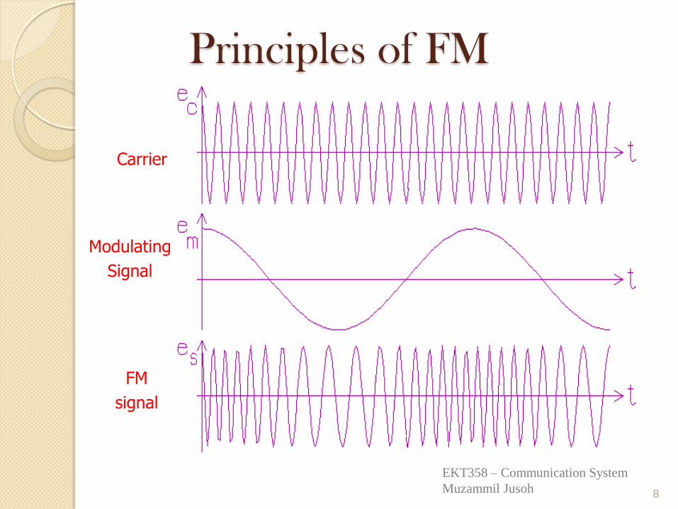
Principles of FM
8
Carrier
Modulating
Signal
FM
signal
EKT358 – Communication System
Muzammil Jusoh
Principles of Phase Modulation, PM
When the amount of phase shift of a constant-frequency carrier is varied in accordance with a modulating signal, the resulting output is a phase-modulation (PM) signal.
Phase modulators produce a phase shift which is a time separation between two sine waves of the same frequency.
The greater the amplitude of the modulating signal, the greater the phase shift.
EKT358 – Communication System
Muzammil Jusoh
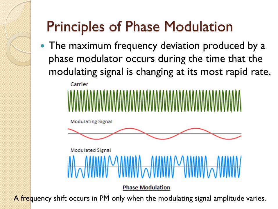
Principles of Phase Modulation
The maximum frequency deviation produced by a
phase modulator occurs during the time that the
modulating signal is changing at its most rapid rate.
A frequency shift occurs in PM only when the modulating signal amplitude varies.
Principles of Phase Modulation
Phase-Shift Keying
◦ The process of phase modulating a carrier
with binary data is called phase-shift keying
(PSK) or binary phase-shift keying
(BPSK).
◦ The PSK signal has a constant frequency, but
the phase of the signal from some reference
changes as the binary modulating signal
occurs.
EKT358 – Communication System
Muzammil Jusoh
Principles of Phase Modulation
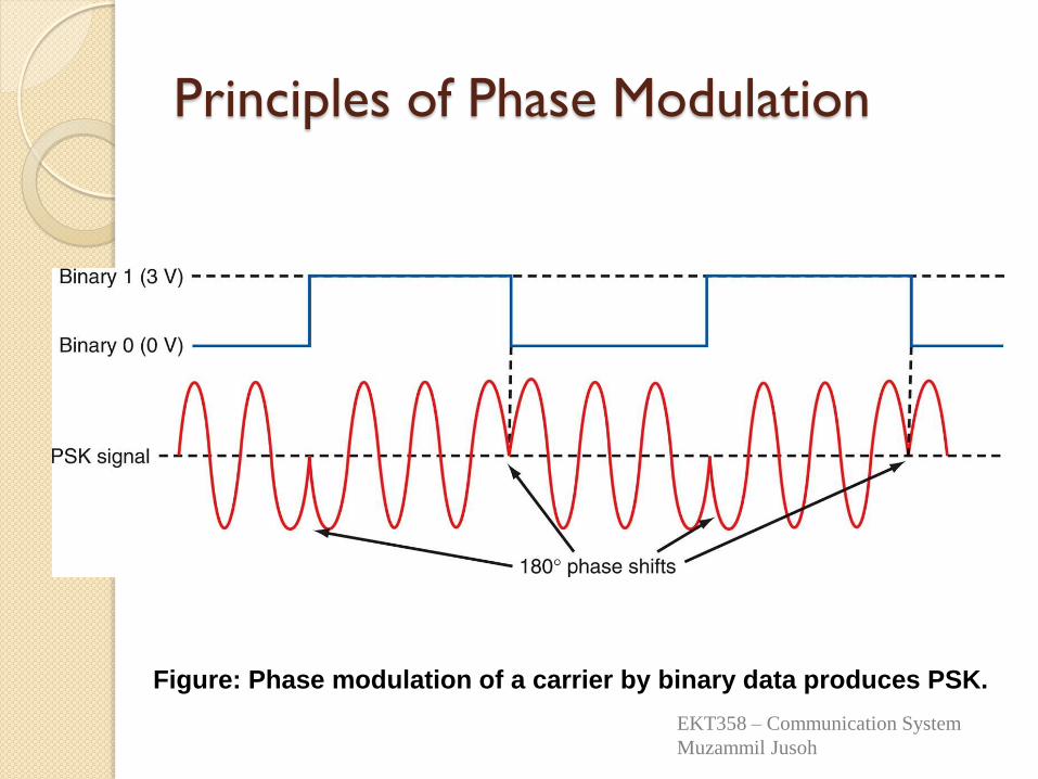
Figure: Phase modulation of a carrier by binary data produces PSK.
EKT358 – Communication System
Muzammil Jusoh
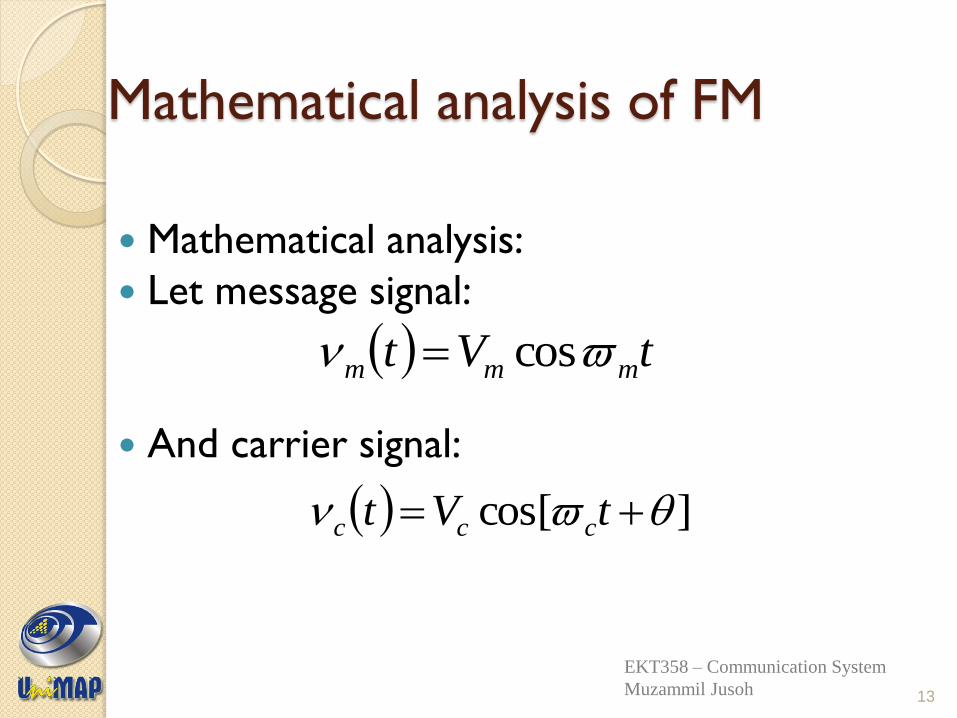
Mathematical analysis of FM
Mathematical analysis:
Let message signal:
And carrier signal:
tVt mmm cos
]cos[ tVt ccc
13
EKT358 – Communication System
Muzammil Jusoh
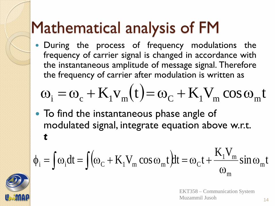
Mathematical analysis of FM During the process of frequency modulations the
frequency of carrier signal is changed in accordance with the instantaneous amplitude of message signal. Therefore the frequency of carrier after modulation is written as
To find the instantaneous phase angle of modulated signal, integrate equation above w.r.t. t
tcosVKtvK mm1Cm1ci
tsinVK
tdttcosVKdt m
m
m1Cmm1Cii
14
EKT358 – Communication System
Muzammil Jusoh
Mathematical analysis of FM
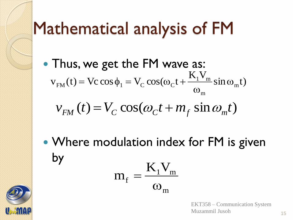
Thus, we get the FM wave as:
Where modulation index for FM is given
by
)tsinVK
tcos(VcosVc)t(v m
m
m1CC1FM
)sincos()( tmtVtv mfCCFM
15
m
m1f
VKm
EKT358 – Communication System
Muzammil Jusoh
Mathematical analysis of FM
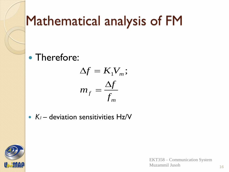
Therefore:
K1 – deviation sensitivities Hz/V
m
f
m
f
fm
VKf
;1
16
EKT358 – Communication System
Muzammil Jusoh
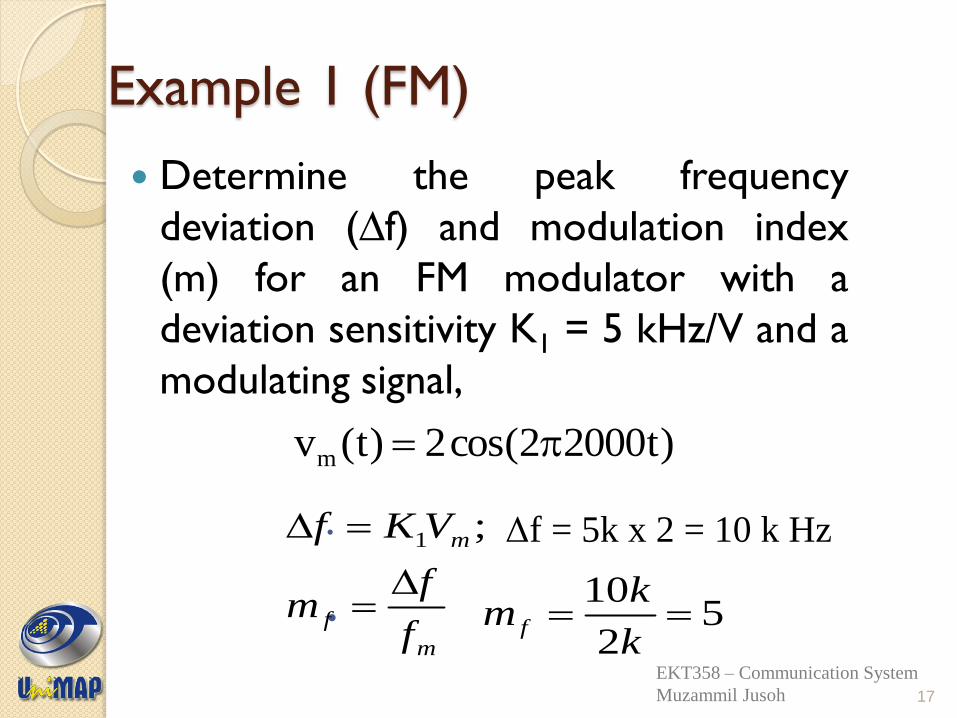
Example 1 (FM)
Determine the peak frequency
deviation (∆f) and modulation index
(m) for an FM modulator with a
deviation sensitivity K1 = 5 kHz/V and a
modulating signal,
Δf = 5k x 2 = 10 k Hz
)t20002cos(2)t(vm
17
m
f
m
f
fm
VKf
;1
52
10
k
km f
EKT358 – Communication System
Muzammil Jusoh
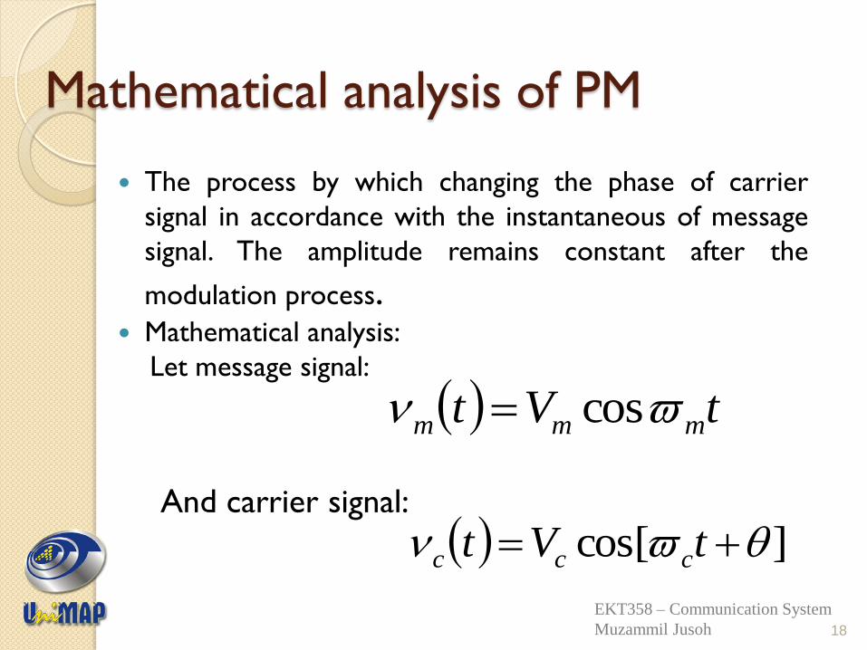
Mathematical analysis of PM
The process by which changing the phase of carrier
signal in accordance with the instantaneous of message
signal. The amplitude remains constant after the
modulation process. Mathematical analysis:
Let message signal:
And carrier signal:
tVt mmm cos
]cos[ tVt ccc
18
EKT358 – Communication System
Muzammil Jusoh
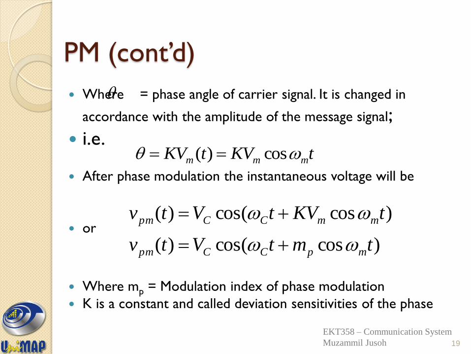
PM (cont’d)
Where = phase angle of carrier signal. It is changed in
accordance with the amplitude of the message signal;
i.e.
After phase modulation the instantaneous voltage will be
or
Where mp = Modulation index of phase modulation
K is a constant and called deviation sensitivities of the phase
tKVtKV mmm cos)(
)coscos()(
)coscos()(
tmtVtv
tKVtVtv
mpCCpm
mmCCpm
19
EKT358 – Communication System
Muzammil Jusoh
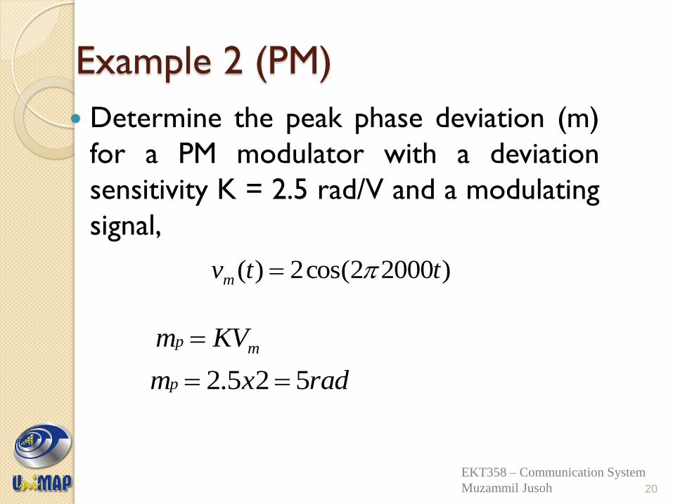
Example 2 (PM)
Determine the peak phase deviation (m)
for a PM modulator with a deviation
sensitivity K = 2.5 rad/V and a modulating
signal,
)20002cos(2)( ttvm
20
mp KVm
radxmp 525.2
EKT358 – Communication System
Muzammil Jusoh
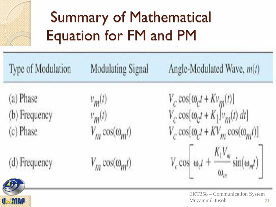
Summary of Mathematical
Equation for FM and PM
21
Tomasi
Electronic Communications Systems, 5e Copyright ©2004 by Pearson Education, Inc.
Upper Saddle River, New Jersey 07458
All rights reserved.
EKT358 – Communication System
Muzammil Jusoh
Modulation Index
and Sidebands
Any modulation process produces sidebands.
When a constant-frequency sine wave modulates a carrier, two side frequencies are produced.
Side frequencies are the sum and difference of the carrier and modulating frequency.
The bandwidth of an FM signal is usually much wider than that of an AM signal with the same modulating signal.
EKT358 – Communication System
Muzammil Jusoh
Modulation Index
and Sidebands Modulation Index ◦ The ratio of the frequency deviation to the
modulating frequency is known as the modulation index (mf).
◦ In most communication systems using FM, maximum limits are put on both the frequency deviation and the modulating frequency.
◦ In standard FM broadcasting, the maximum permitted frequency deviation is 75 kHz and the maximum permitted modulating frequency is 15 kHz.
◦ The modulation index for standard FM broadcasting is therefore 5.
EKT358 – Communication System
Muzammil Jusoh
Modulation Index
and Sidebands
Bessel Functions
◦ The equation that expresses the phase angle
in terms of the sine wave modulating signal is
solved with a complex mathematical process
known as Bessel functions.
◦ Bessel coefficients are widely available and it is
not necessary to memorize or calculate them.
EKT358 – Communication System
Muzammil Jusoh
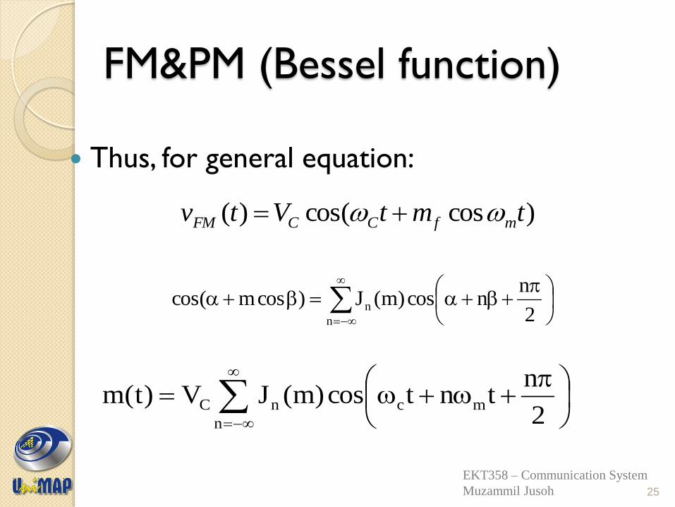
FM&PM (Bessel function)
Thus, for general equation:
)coscos()( tmtVtv mfCCFM
2
nncos)m(J)cosmcos(
n
n
25
n
mcnC2
ntntcos)m(JV)t(m
EKT358 – Communication System
Muzammil Jusoh
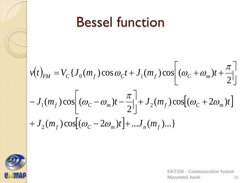
Bessel function
)...}(...)2(cos)(
)2(cos)(2
)(cos)(
2)(cos)(cos)({
2
21
10
fnmCf
mCfmCf
mCfCfCFM
mJtmJ
tmJtmJ
tmJtmJVtv
26
EKT358 – Communication System
Muzammil Jusoh
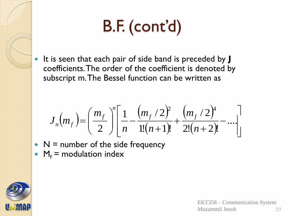
B.F. (cont’d)
It is seen that each pair of side band is preceded by J coefficients. The order of the coefficient is denoted by subscript m. The Bessel function can be written as
N = number of the side frequency Mf = modulation index
....
!2!2
2/
!1!1
2/1
2
42
n
m
n
m
n
mmJ
ff
n
f
fn
27
EKT358 – Communication System
Muzammil Jusoh
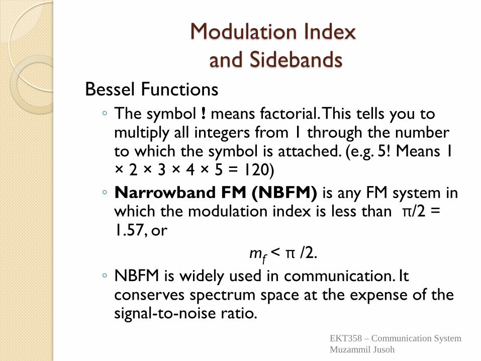
Modulation Index
and Sidebands
Bessel Functions
◦ The symbol ! means factorial. This tells you to multiply all integers from 1 through the number to which the symbol is attached. (e.g. 5! Means 1 × 2 × 3 × 4 × 5 = 120)
◦ Narrowband FM (NBFM) is any FM system in which the modulation index is less than π/2 = 1.57, or
mf < π /2.
◦ NBFM is widely used in communication. It conserves spectrum space at the expense of the signal-to-noise ratio.
EKT358 – Communication System
Muzammil Jusoh
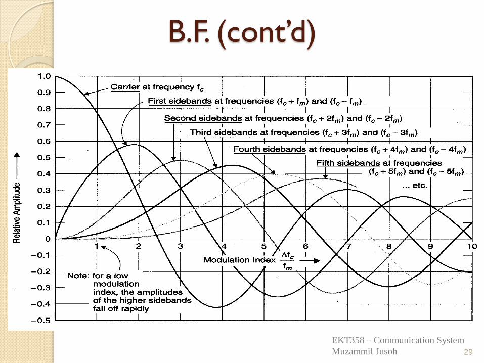
B.F. (cont’d)
29
EKT358 – Communication System
Muzammil Jusoh
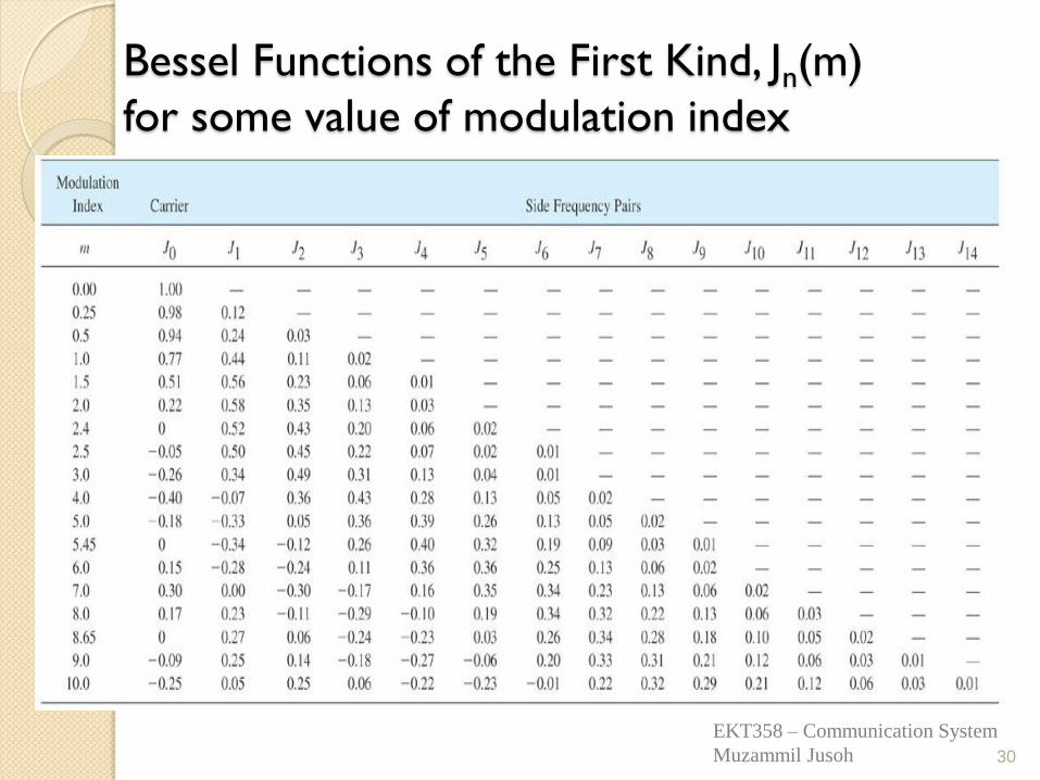
Bessel Functions of the First Kind, Jn(m)
for some value of modulation index
30
EKT358 – Communication System
Muzammil Jusoh
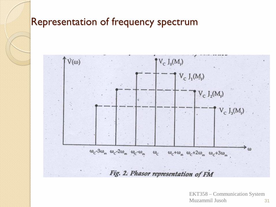
Representation of frequency spectrum
31
EKT358 – Communication System
Muzammil Jusoh
Example 3
For an FM modulator with a modulation index m = 1, a modulating signal vm(t) = Vm sin(2π1000t), and an unmodulated carrier vc(t) = 10 sin(2π500kt). Determine the number of sets of significant side frequencies and their amplitudes. Then, draw the frequency spectrum showing their relative amplitudes.
32
EKT358 – Communication System
Muzammil Jusoh
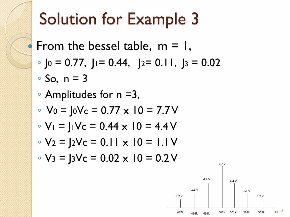
Solution for Example 3
From the bessel table, m = 1,
◦ J0 = 0.77, J1= 0.44, J2= 0.11, J3 = 0.02
◦ So, n = 3
◦ Amplitudes for n =3,
◦ V0 = J0Vc = 0.77 x 10 = 7.7 V
◦ V1 = J1Vc = 0.44 x 10 = 4.4 V
◦ V2 = J2Vc = 0.11 x 10 = 1.1 V
◦ V3 = J3Vc = 0.02 x 10 = 0.2 V
EKT343 –Principle of Communication
Engineering 33
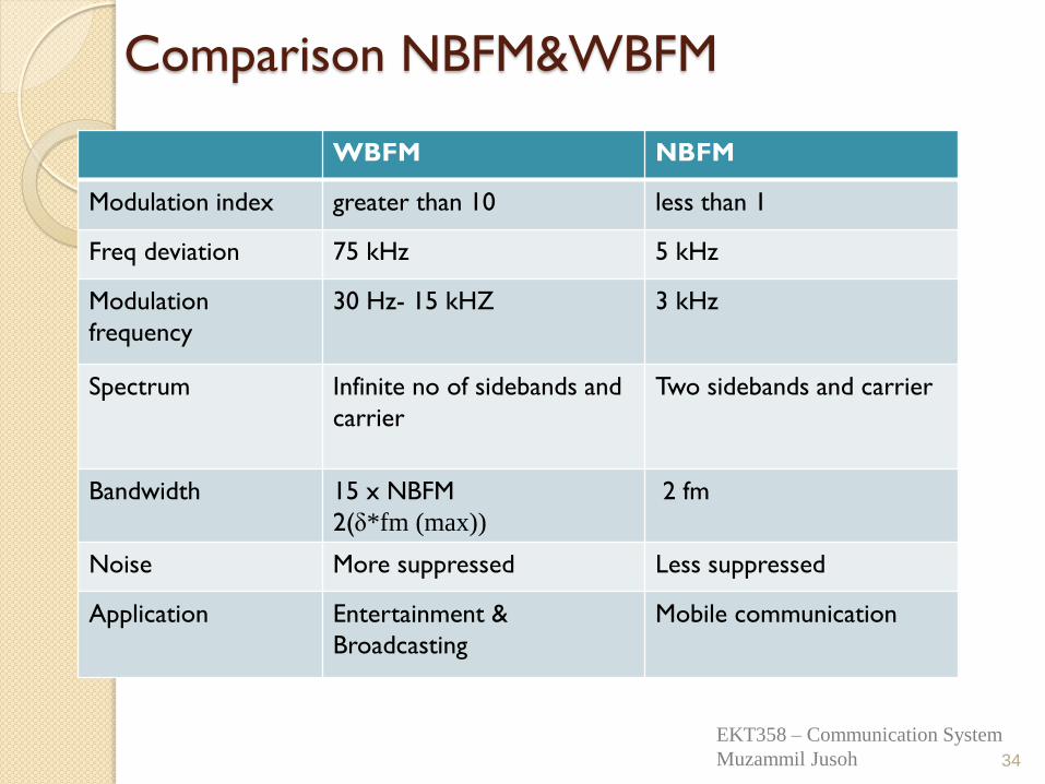
Comparison NBFM&WBFM
34
WBFM NBFM
Modulation index greater than 10 less than 1
Freq deviation 75 kHz 5 kHz
Modulation
frequency
30 Hz- 15 kHZ 3 kHz
Spectrum Infinite no of sidebands and
carrier
Two sidebands and carrier
Bandwidth 15 x NBFM
2(δ*fm (max))
2 fm
Noise More suppressed Less suppressed
Application Entertainment &
Broadcasting
Mobile communication
EKT358 – Communication System
Muzammil Jusoh
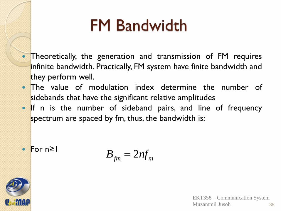
FM Bandwidth
Theoretically, the generation and transmission of FM requires
infinite bandwidth. Practically, FM system have finite bandwidth and
they perform well.
The value of modulation index determine the number of
sidebands that have the significant relative amplitudes
If n is the number of sideband pairs, and line of frequency
spectrum are spaced by fm, thus, the bandwidth is:
For n≥1
mfm nfB 2
35
EKT358 – Communication System
Muzammil Jusoh
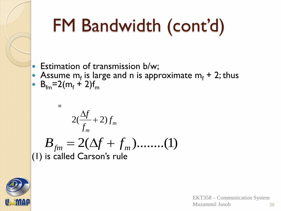
FM Bandwidth (cont’d)
Estimation of transmission b/w; Assume mf is large and n is approximate mf + 2; thus Bfm=2(mf + 2)fm
= (1) is called Carson’s rule
m
m
ff
f)2(2
36
)1)........((2 mfm ffB
EKT358 – Communication System
Muzammil Jusoh
Example 4
For an FM modulator with a peak frequency deviation, Δf = 10 kHz, a modulating-signal frequency fm = 10 kHz,
Vc = 10 V and a 500 kHz carrier, determine ◦ Actual minimum bandwidth from the Bessel function
table.
◦ Approximate minimum bandwidth using Carson’s rule.
◦ Plot the output frequency spectrum for the Bessel approximation.
37
EKT358 – Communication System
Muzammil Jusoh
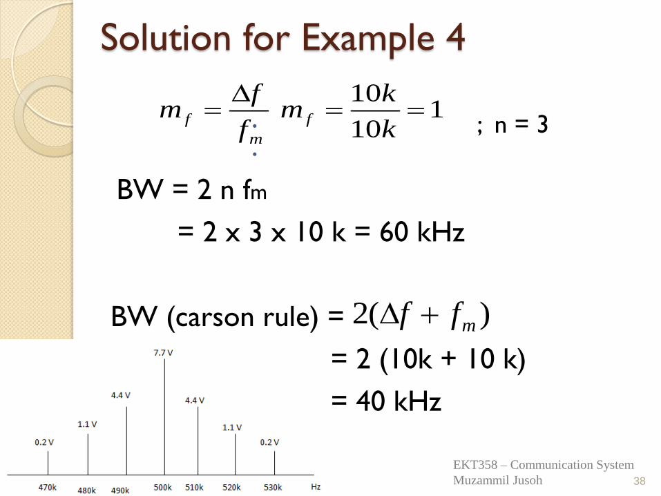
Solution for Example 4
; n = 3
BW = 2 n fm
= 2 x 3 x 10 k = 60 kHz
BW (carson rule) =
= 2 (10k + 10 k)
= 40 kHz
38
m
ff
fm
1
10
10
k
km f
)(2 mff
EKT358 – Communication System
Muzammil Jusoh
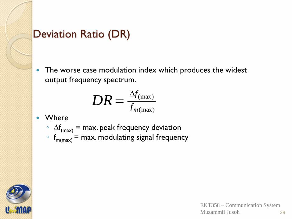
Deviation Ratio (DR)
The worse case modulation index which produces the widest
output frequency spectrum.
Where
◦ ∆f(max) = max. peak frequency deviation
◦ fm(max) = max. modulating signal frequency
(max)
(max)
mf
fDR
39
EKT358 – Communication System
Muzammil Jusoh
Example 5
Determine the deviation ratio and bandwidth for the worst-case (widest-bandwidth) modulation index for an FM broadcast-band transmitter with a maximum frequency deviation of 75 kHz and a maximum modulating-signal frequency of 15 kHz.
Determine the deviation ratio and maximum bandwidth for an equal modulation index with only half the peak frequency deviation and modulating-signal frequency.
40
EKT358 – Communication System
Muzammil Jusoh
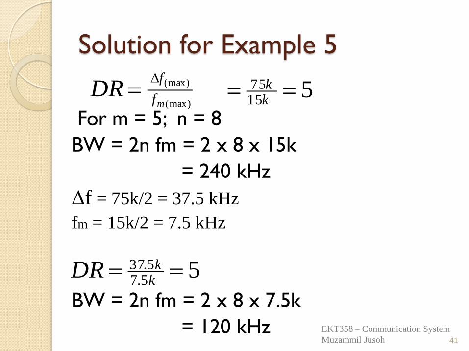
Solution for Example 5
For m = 5; n = 8
BW = 2n fm = 2 x 8 x 15k
= 240 kHz
Δf = 75k/2 = 37.5 kHz
fm = 15k/2 = 7.5 kHz
BW = 2n fm = 2 x 8 x 7.5k
= 120 kHz
41
(max)
(max)
mf
fDR
5
1575
kk
55.75.37 kkDR
EKT358 – Communication System
Muzammil Jusoh
Angle Modulation
Part 2
Power distribution of FM
Generation & Demodulation of FM
Noise in FM
Application of FM
42
EKT358 – Communication System
Muzammil Jusoh
FM Power Distribution
As seen in Bessel function table, it shows that as the sideband relative amplitude increases, the carrier amplitude,J0 decreases.
This is because, in FM, the total transmitted power
is always constant and the total average power is equal to the unmodulated carrier power, that is the amplitude of the FM remains constant whether or not it is modulated.
43
EKT358 – Communication System
Muzammil Jusoh
FM Power Distribution (cont’d)
In effect, in FM, the total power that is originally in the
carrier is redistributed between all components of the
spectrum, in an amount determined by the modulation
index, mf, and the corresponding Bessel functions.
At certain value of modulation index, the carrier
component goes to zero, where in this condition, the
power is carried by the sidebands only.
44
EKT358 – Communication System
Muzammil Jusoh
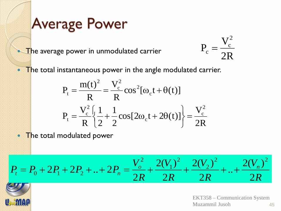
Average Power
The average power in unmodulated carrier
The total instantaneous power in the angle modulated carrier.
The total modulated power
R2
VP
2
cc
R2
V)]t(2t2cos[
2
1
2
1
R
VP
)]t(t[cosR
V
R
)t(mP
2
cc
2
ct
c
22
c
2
t
45
R
V
R
V
R
V
R
VPPPPP no
nt2
)(2..
2
)(2
2
)(2
22..22
22
2
2
1
2
210
EKT358 – Communication System
Muzammil Jusoh
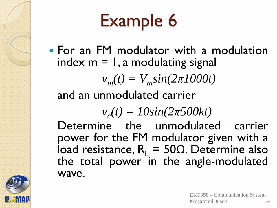
Example 6
For an FM modulator with a modulation index m = 1, a modulating signal
vm(t) = Vmsin(2π1000t)
and an unmodulated carrier
vc(t) = 10sin(2π500kt)
Determine the unmodulated carrier power for the FM modulator given with a load resistance, RL = 50Ω. Determine also the total power in the angle-modulated wave.
46
EKT358 – Communication System
Muzammil Jusoh
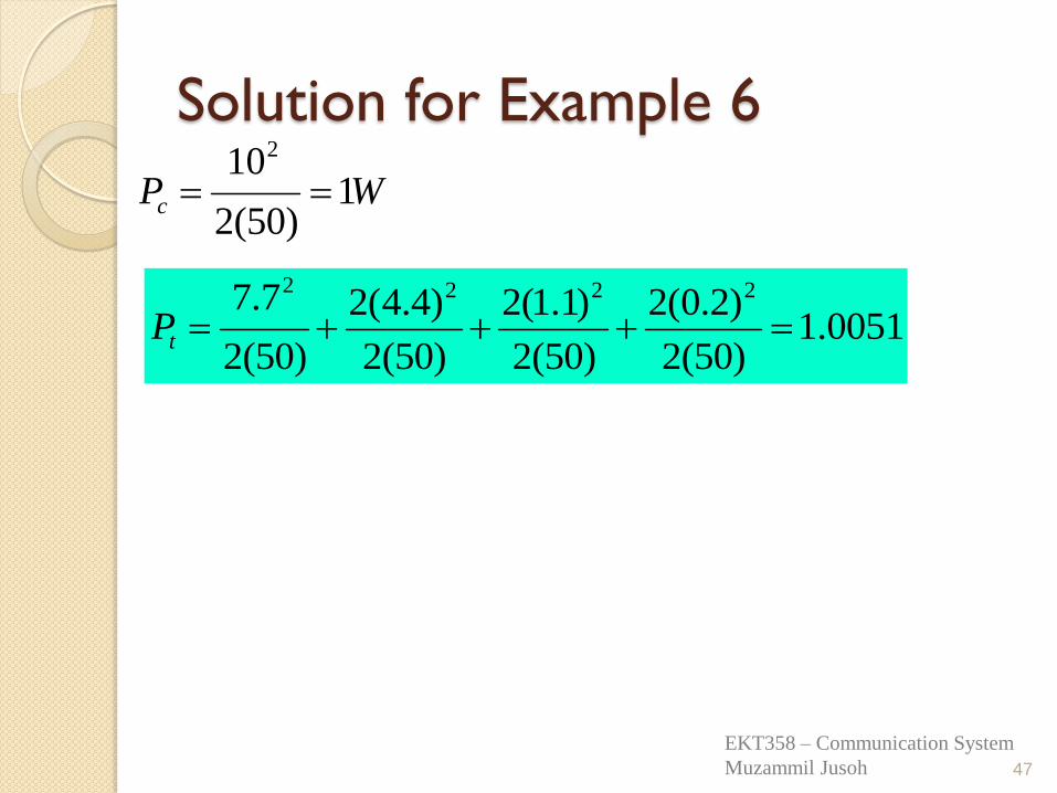
Solution for Example 6
47
0051.1)50(2
)2.0(2
)50(2
)1.1(2
)50(2
)4.4(2
)50(2
7.7 2222
tP
WPc 1)50(2
102
EKT358 – Communication System
Muzammil Jusoh
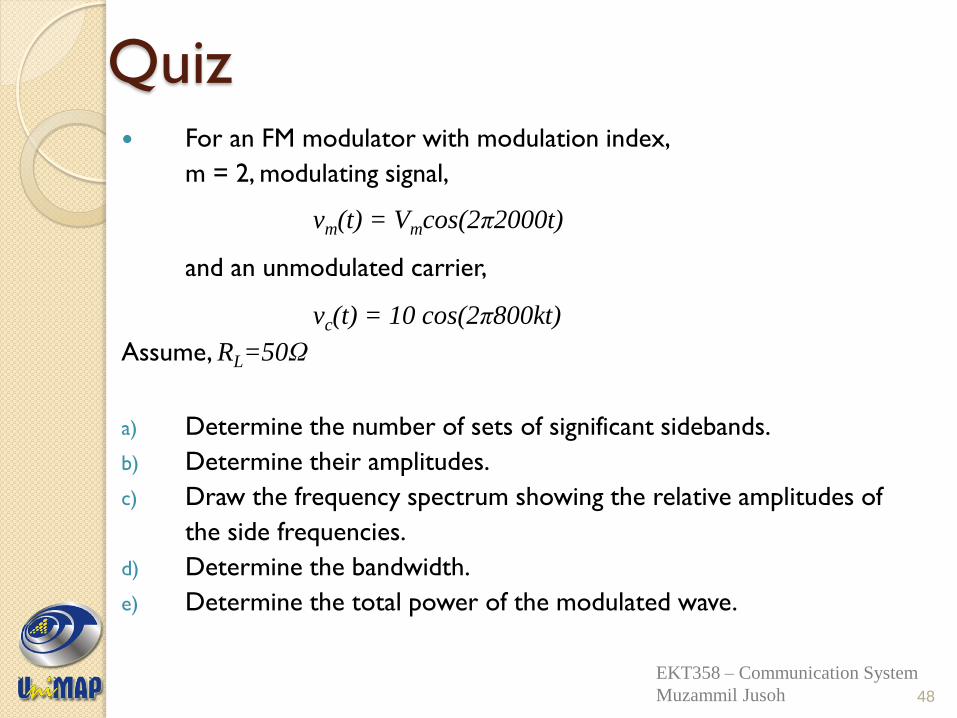
Quiz For an FM modulator with modulation index,
m = 2, modulating signal,
vm(t) = Vmcos(2π2000t)
and an unmodulated carrier,
vc(t) = 10 cos(2π800kt)
Assume, RL=50Ω
a) Determine the number of sets of significant sidebands.
b) Determine their amplitudes.
c) Draw the frequency spectrum showing the relative amplitudes of
the side frequencies.
d) Determine the bandwidth.
e) Determine the total power of the modulated wave.
48
EKT358 – Communication System
Muzammil Jusoh
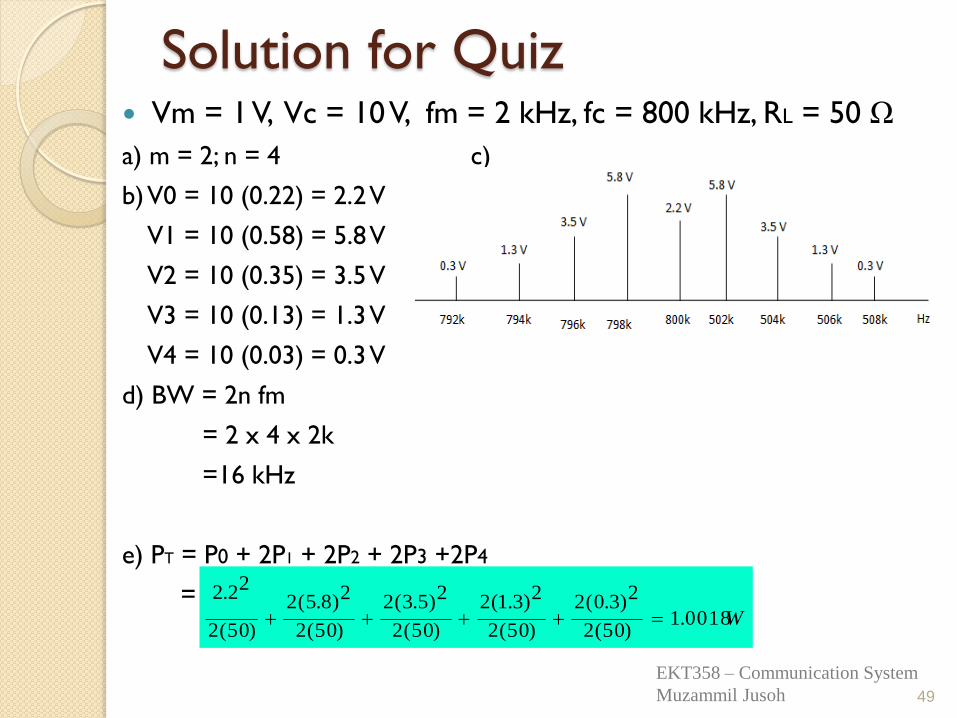
Solution for Quiz Vm = 1 V, Vc = 10 V, fm = 2 kHz, fc = 800 kHz, RL = 50 Ω
a) m = 2; n = 4 c)
b) V0 = 10 (0.22) = 2.2 V
V1 = 10 (0.58) = 5.8 V
V2 = 10 (0.35) = 3.5 V
V3 = 10 (0.13) = 1.3 V
V4 = 10 (0.03) = 0.3 V
d) BW = 2n fm
= 2 x 4 x 2k
=16 kHz
e) PT = P0 + 2P1 + 2P2 + 2P3 +2P4
=
49
W0018.1)50(2
2)3.0(2
)50(2
2)3.1(2
)50(2
2)5.3(2
)50(2
2)8.5(2
)50(2
22.2
EKT358 – Communication System
Muzammil Jusoh
Generation of FM
Two major FM generation: i) Direct method:
i) straight forward, requires a VCO whose oscillation
frequency has linear dependence on applied voltage.
ii) Advantage: large frequency deviation
iii) Disadvantage: the carrier frequency tends to drift and
must be stabilized.
iv) Common methods: i) FM Reactance modulators
ii) Varactor diode modulators
50
EKT358 – Communication System
Muzammil Jusoh
Generation of FM (cont’d)
ii) Indirect method: i. Frequency-up conversion.
ii. Two ways: a. Heterodyne method
b. Multiplication method
iii. One most popular indirect method is the Armstrong
modulator
51
EKT358 – Communication System
Muzammil Jusoh
52
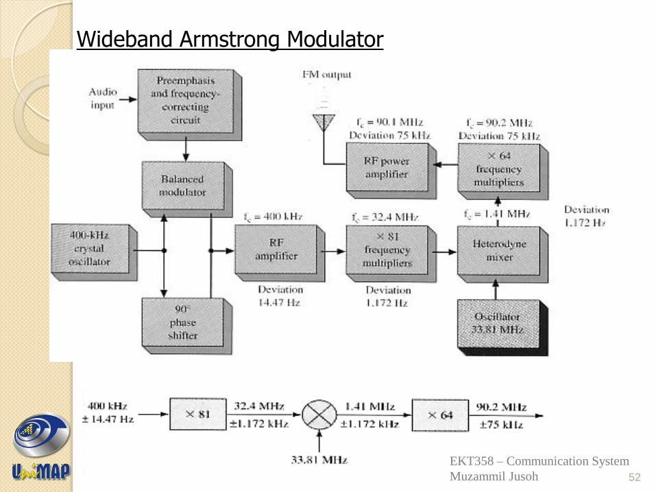
Wideband Armstrong Modulator
EKT358 – Communication System
Muzammil Jusoh
A complete Armstrong modulator is supposed to
provide a 75kHz frequency deviation. It uses a
balanced modulator and 90o phase shifter to phase-
modulate a crystal oscillator. Required deviation is
obtained by combination of multipliers and mixing,
raise the signal from
suitable for broadcasting.
Armstrong Modulator
53
kHz75MHz2.90toHz47.14kHz400
EKT358 – Communication System
Muzammil Jusoh
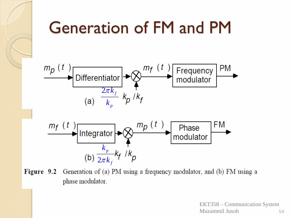
Generation of FM and PM
54
2 f
p
k
k
2
p
f
k
k
EKT358 – Communication System
Muzammil Jusoh
FM Detection/Demodulation FM demodulation ◦ is a process of getting back or regenerate the
original modulating signal from the modulated FM signal.
◦ It can be achieved by converting the frequency
deviation of FM signal to the variation of equivalent voltage.
◦ The demodulator will produce an output where
its instantaneous amplitude is proportional to the instantaneous frequency of the input FM signal.
55
EKT358 – Communication System
Muzammil Jusoh
FM detection (cont’d)
To detect an FM signal, it is necessary to have a circuit whose output voltage varies linearly with the frequency of the input signal.
The most commonly used demodulator is the PLL
demodulator. Can be use to detect either NBFM or WBFM.
56
EKT358 – Communication System
Muzammil Jusoh
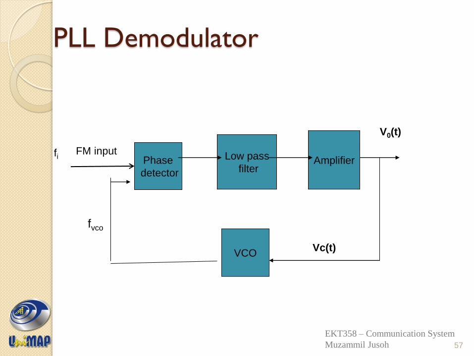
PLL Demodulator
57
Phase
detector
VCO
Low pass
filter Amplifier
FM input
Vc(t)
fvco
V0(t)
fi
EKT358 – Communication System
Muzammil Jusoh
PLL Demodulator
The phase detector produces an average output voltage
that is linear function of the phase difference between
the two input signals. Then low frequency component is
pass through the LPF to get a small dc average voltage
to the amplifier.
After amplification, part of the signal is fed back through
VCO where it results in frequency modulation of the
VCO frequency. When the loop is in lock, the VCO
frequency follows or tracks the incoming frequency.
58
EKT358 – Communication System
Muzammil Jusoh
PLL Demodulator
Let instantaneous freq of FM Input,
fi(t)=fc +k1vm(t),
and the VCO output frequency,
f VCO(t)=f0 + k2Vc(t);
f0 is the free running frequency.
For the VCO frequency to track the
instantaneous incoming frequency,
fvco = fi;
59
EKT358 – Communication System
Muzammil Jusoh
PLL Demodulator
f0 + k2Vc(t)= fc +k1vm(t), so,
If VCO can be tuned so that fc=f0, then
Where Vc(t) is also taken as the output voltage, which therefore is the demodulated output
)()( 10 tvkfftV mcc
)()( 1 tvktV mc
60
EKT358 – Communication System
Muzammil Jusoh
Noise in FM Noise is interference generated by
lightning, motors, automotive ignition systems, and power line switching that produces transient signals.
Noise is typically narrow spikes of voltage with high frequencies.
Noise (voltage spikes) add to a signal and interfere with it.
Some noise completely obliterates signal information.
61
EKT358 – Communication System
Muzammil Jusoh
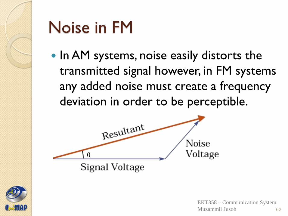
Noise in FM
In AM systems, noise easily distorts the
transmitted signal however, in FM systems
any added noise must create a frequency
deviation in order to be perceptible.
62
θ
EKT358 – Communication System
Muzammil Jusoh
Noise in FM(Cont’d)
The maximum frequency deviation due to random noise occurs when the noise is at right angles to the resultant signal. In the worst case the signal frequency has been deviated by:
δ = θfm
This shows that the deviation due to noise increases as the modulation frequency increases. Since noise power is the square of the noise voltage, the signal to noise ratio can significantly degrade.
Noise occurs predominantly at the highest frequencies within the baseband
63
EKT358 – Communication System
Muzammil Jusoh
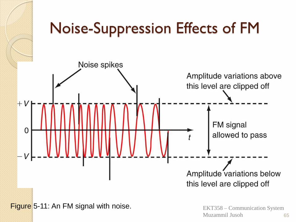
Noise-Suppression Effects of FM
FM signals have a constant modulated carrier amplitude.
FM receivers contain limiter circuits that deliberately restrict the amplitude of the received signal.
Any amplitude variations occurring on the FM signal are effectively clipped by limiter circuits.
This amplitude clipping does not affect the information content of the FM signal, since it is contained solely within the frequency variations of the carrier.
64
EKT358 – Communication System
Muzammil Jusoh
Noise-Suppression Effects of FM
65
Figure 5-11: An FM signal with noise. EKT358 – Communication System
Muzammil Jusoh
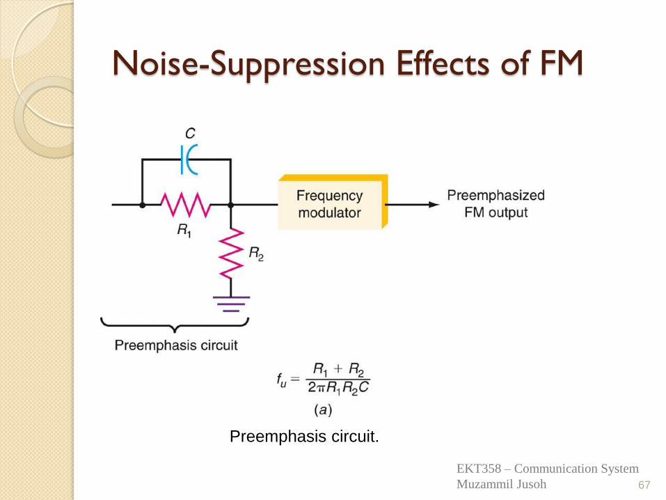
Noise-Suppression Effects of FM
Preemphasis ◦ Noise can interfere with an FM signal and
particularly with the high-frequency components of the modulating signal. ◦ Noise is primarily sharp spikes of energy and
contains a lot of harmonics and other high-frequency components. ◦ To overcome high-frequency noise, a
technique known as preemphasis is used. ◦ A simple high-pass filter can serve as a
transmitter’s pre-emphasis circuit. ◦ Pre-emphasis provides more amplification of
only high-frequency components.
66
EKT358 – Communication System
Muzammil Jusoh
Noise-Suppression Effects of FM
67
Preemphasis circuit.
EKT358 – Communication System
Muzammil Jusoh
Noise-Suppression Effects of FM
Preemphasis ◦ A simple low-pass filter can operate as a
deemphasis circuit in a receiver. ◦ A deemphasis circuit returns the frequency
response to its normal flat level. ◦ The combined effect of preemphasis and
deemphasis is to increase the signal-to-noise ratio for the high-frequency components during transmission so that they will be stronger and not masked by noise.
68
EKT358 – Communication System
Muzammil Jusoh
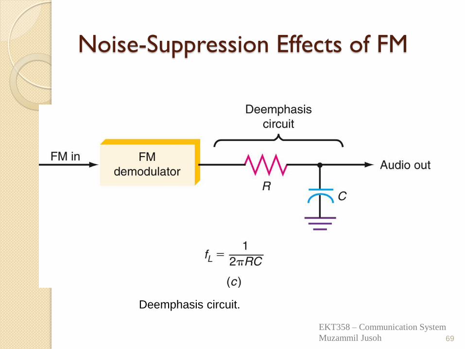
Noise-Suppression Effects of FM
69
Deemphasis circuit.
EKT358 – Communication System
Muzammil Jusoh
Application of FM
FM is commonly used at VHF radio frequencies for high-fidelity broadcasts of music and speech (FM broadcasting). Normal (analog) TV sound is also broadcast using FM. The type of FM used in broadcast is generally called wide-FM, or W-FM
A narrowband form is used for voice communications in commercial and amateur radio settings. In two-way radio, narrowband narrow-fm (N-FM) is used to conserve bandwidth. In addition, it is used to send signals into space.
70
EKT358 – Communication System
Muzammil Jusoh
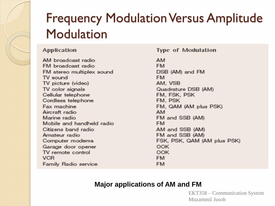
Frequency Modulation Versus Amplitude
Modulation
Major applications of AM and FM
EKT358 – Communication System
Muzammil Jusoh
Advantages Wideband FM gives significant improvement in the SNR at the
output of the RX which proportional to the square of
modulation index.
Angle modulation is resistant to propagation-induced selective
fading since amplitude variations are unimportant and are
removed at the receiver using a limiting circuit.
Angle modulation is very effective in rejecting interference.
(minimizes the effect of noise).
Angle modulation allows the use of more efficient transmitter
power in information.
Angle modulation is capable of handing a greater dynamic range
of modulating signal without distortion than AM.
72
EKT358 – Communication System
Muzammil Jusoh
Disadvantages Angle modulation requires a transmission
bandwidth much larger than the message
signal bandwidth.
Angle modulation requires more complex
and expensive circuits than AM.
73
EKT358 – Communication System
Muzammil Jusoh
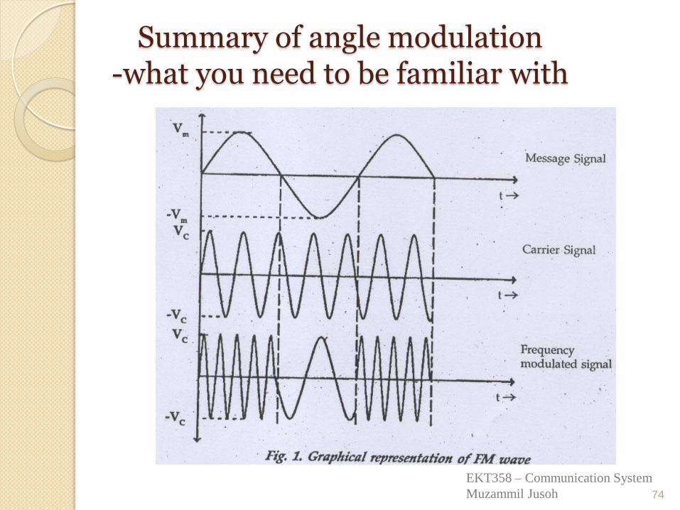
Summary of angle modulation -what you need to be familiar with
74
EKT358 – Communication System
Muzammil Jusoh
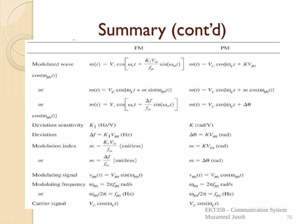
Summary (cont’d)
75
EKT358 – Communication System
Muzammil Jusoh
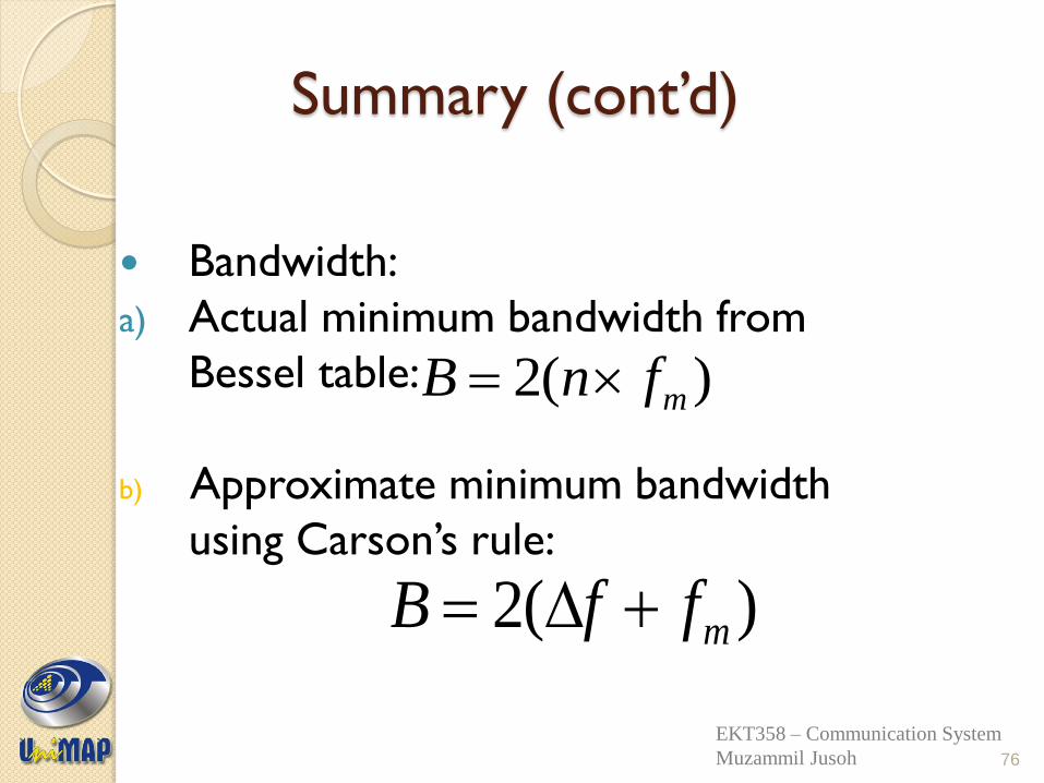
Summary (cont’d)
Bandwidth:
a) Actual minimum bandwidth from
Bessel table:
b) Approximate minimum bandwidth
using Carson’s rule:
)(2 mfnB
)(2 mffB
76
EKT358 – Communication System
Muzammil Jusoh
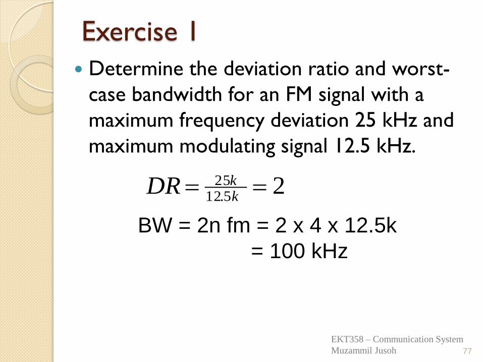
Exercise 1
Determine the deviation ratio and worst-
case bandwidth for an FM signal with a
maximum frequency deviation 25 kHz and
maximum modulating signal 12.5 kHz.
77
25.12
25 kkDR
BW = 2n fm = 2 x 4 x 12.5k
= 100 kHz
EKT358 – Communication System
Muzammil Jusoh
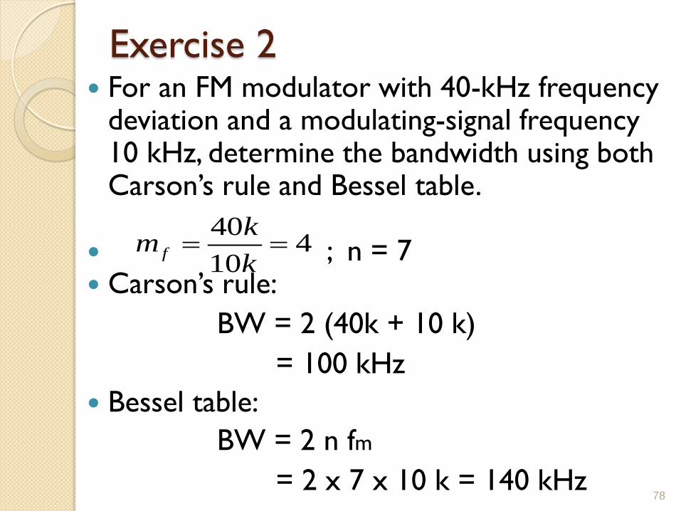
Exercise 2 For an FM modulator with 40-kHz frequency
deviation and a modulating-signal frequency 10 kHz, determine the bandwidth using both Carson’s rule and Bessel table.
; n = 7 Carson’s rule:
BW = 2 (40k + 10 k)
= 100 kHz
Bessel table:
BW = 2 n fm
= 2 x 7 x 10 k = 140 kHz
78
410
40
k
km f
Exercise 3
For an FM modulator with an
unmodulated carrier amplitude 20 V, a
modulation index, m = 1, and a load
resistance of 10-ohm, determine the
power in the modulated carrier and each
side frequency, and sketch the power
spectrum for the modulated wave.
79
EKT358 – Communication System
Muzammil Jusoh
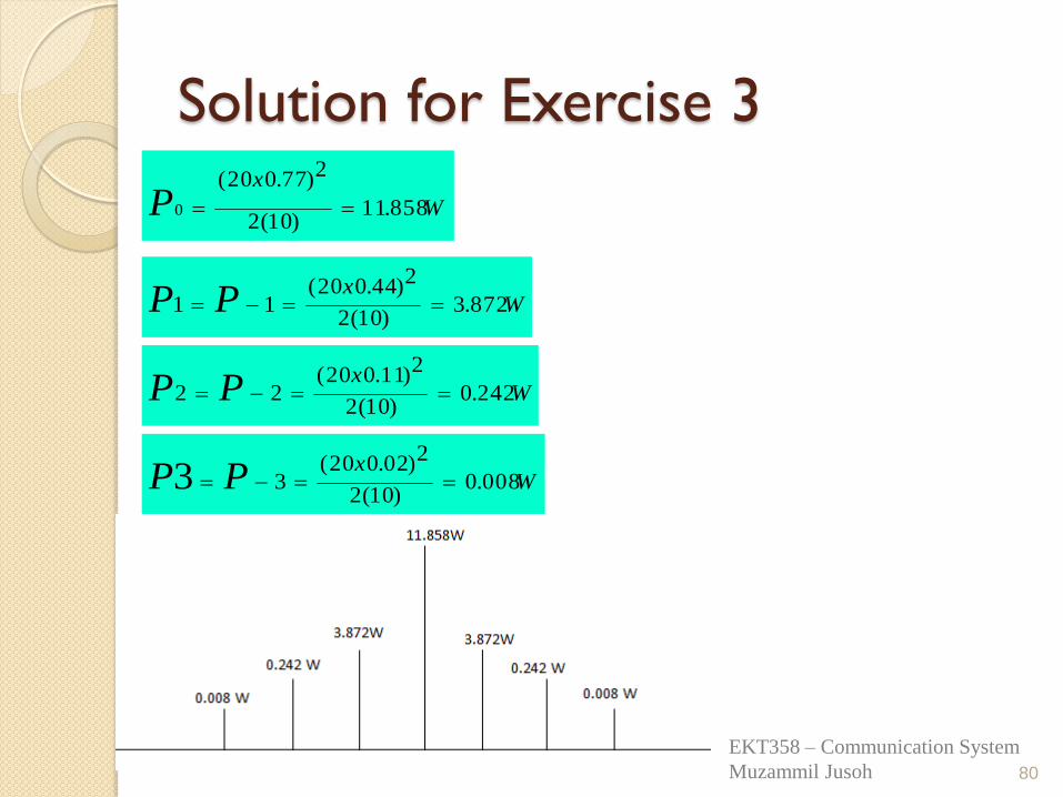
Solution for Exercise 3
80
W
x
P 858.11)10(2
2)77.020(
0
Wx
PP 872.3)10(2
2)44.020(11
Wx
PP 242.0)10(2
2)11.020(22
Wx
PP 008.0)10(2
2)02.020(33
EKT358 – Communication System
Muzammil Jusoh
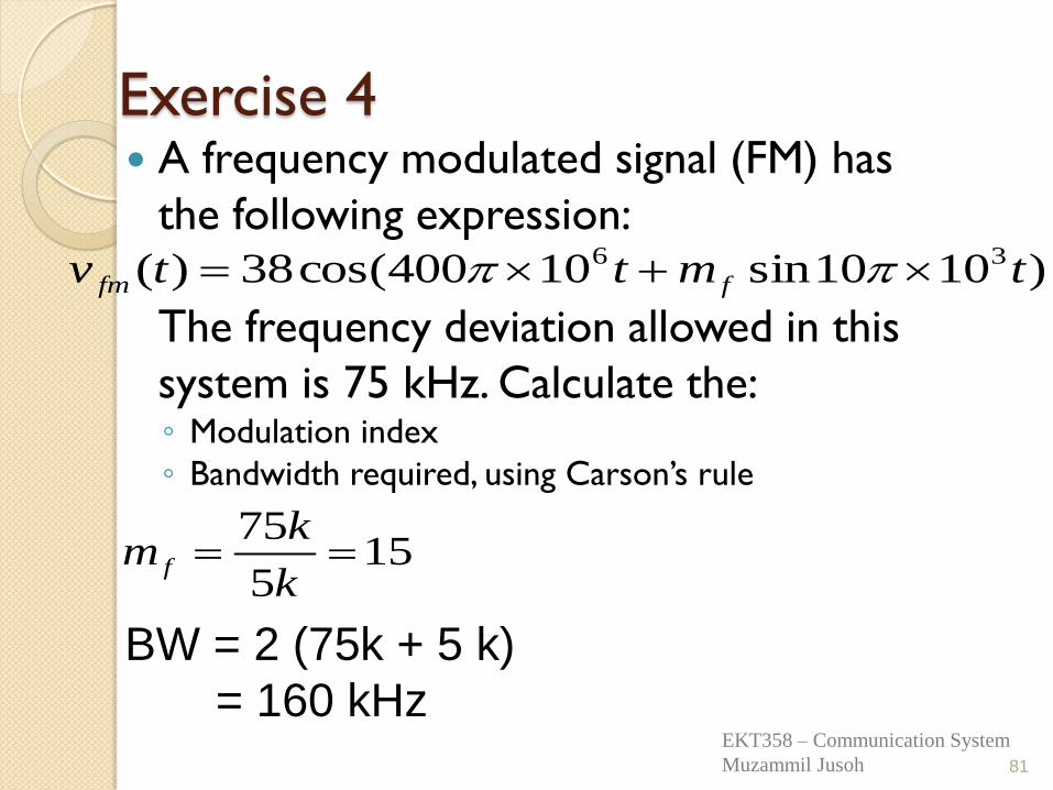
Exercise 4 A frequency modulated signal (FM) has
the following expression:
The frequency deviation allowed in this
system is 75 kHz. Calculate the: ◦ Modulation index
◦ Bandwidth required, using Carson’s rule
)1010sin10400cos(38)( 36 tmttv ffm
81
155
75
k
km f
BW = 2 (75k + 5 k)
= 160 kHz EKT358 – Communication System
Muzammil Jusoh
END OF ANGLE
MODULATION
82
EKT358 – Communication System
Muzammil Jusoh


![UNIVERSITI MALAYSIA PERLIS - portal.unimap.edu.myportal.unimap.edu.my/portal/page/portal30/STD_ACA_BULL_BOARD/ABB...EAT472 Kejuruteraan Air Sisa Termaju [Advanced Wastewater Engineering]](https://img.pdfslide.net/doc/110x75/5d48251a88c99344508b6af1/universiti-malaysia-perlis-kejuruteraan-air-sisa-termaju-advanced-wastewater.jpg)
![Aggregate Planning - portal.unimap.edu.myportal.unimap.edu.my/portal/page/portal30/Lecture Notes/KEJURUTERAAN...Chapter 05 - ENT 489 [1011] 2 Aggregate Planning Goal: To plan gross](https://img.pdfslide.net/doc/110x75/5d5fcf1b88c993c53c8bb3a6/aggregate-planning-noteskejuruteraanchapter-05-ent-489-1011-2-aggregate.jpg)


![UNIVERSITI MALAYSIA PERLIS - portal.unimap.edu.myportal.unimap.edu.my/portal/page/portal30/STD_ACA_BULL_BOARD/ABB...Keusahawanan Kejuruteraan [Engineering Entrepreneurship] BFT110](https://img.pdfslide.net/doc/110x75/5e06fe40a88f4c0645780452/universiti-malaysia-perlis-kejuruteraan-engineering-entrepreneurship-bft110.jpg)