Embed Size (px)
Citation preview
1
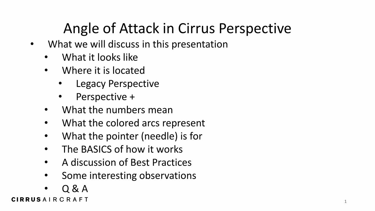
Angle of Attack in Cirrus Perspective • What we will discuss in this presentation
• What it looks like • Where it is located
• Legacy Perspective • Perspective +
• What the numbers mean • What the colored arcs represent • What the pointer (needle) is for • The BASICS of how it works • A discussion of Best Practices • Some interesting observations • Q & A

2
What it looks like What do the numbers mean? • Garmin
• Normalized to 1.0 • 1.0 = STALL • .60 = 1.3 Vs AT CURRENT A/C
WEIGHT : THIS IS THE MAGIC NUMBER FOR APPROACH TO LANDING
• Number below ‘AOA’ = Current AOA
• .20 = Don’t worry about it! • Others
• Percent of Critical AOA • 1.0 = 100% wing at Critical AOA
• No reserve lift • .60 = 60% of Critical AOA 1.3 Vs
• 40% below Critical AOA • .20 = Don’t worry about it.
3
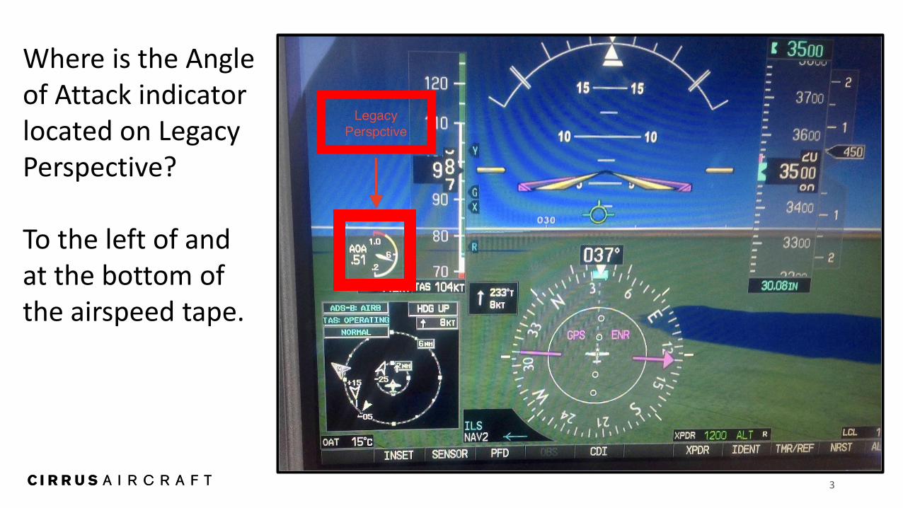
Where is the Angle of Attack indicator located on Legacy Perspective? To the left of and at the bottom of the airspeed tape.
4
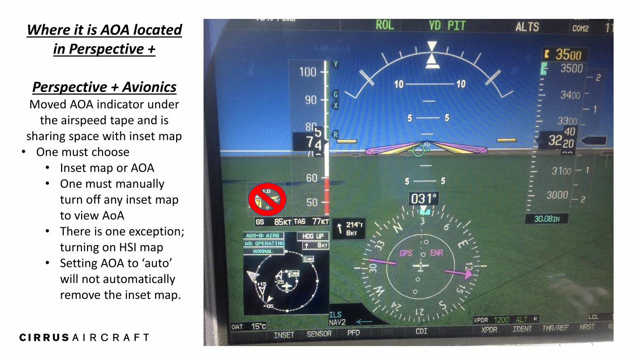
Where it is AOA located in Perspective +
Perspective + Avionics
Moved AOA indicator under the airspeed tape and is
sharing space with inset map • One must choose
• Inset map or AOA • One must manually
turn off any inset map to view AoA
• There is one exception; turning on HSI map
• Setting AOA to ‘auto’ will not automatically remove the inset map.
5
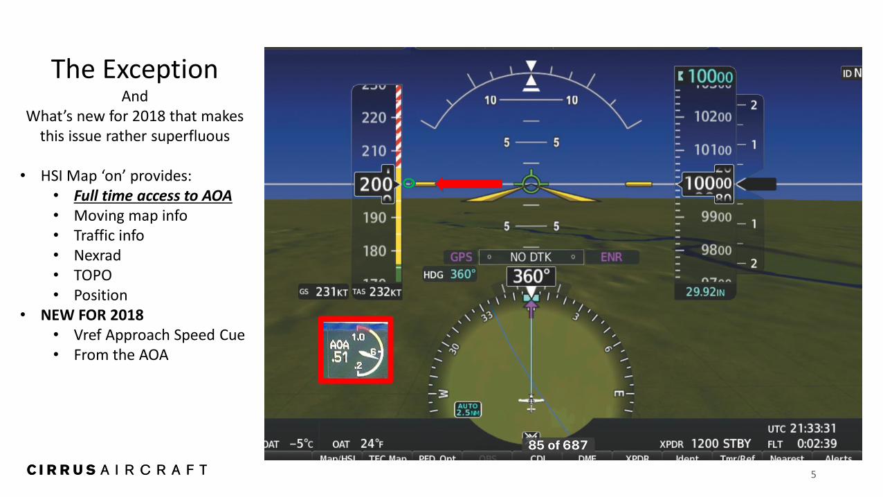
The Exception And
What’s new for 2018 that makes this issue rather superfluous
• HSI Map ‘on’ provides:
• Full time access to AOA • Moving map info • Traffic info • Nexrad • TOPO • Position
• NEW FOR 2018 • Vref Approach Speed Cue • From the AOA
6
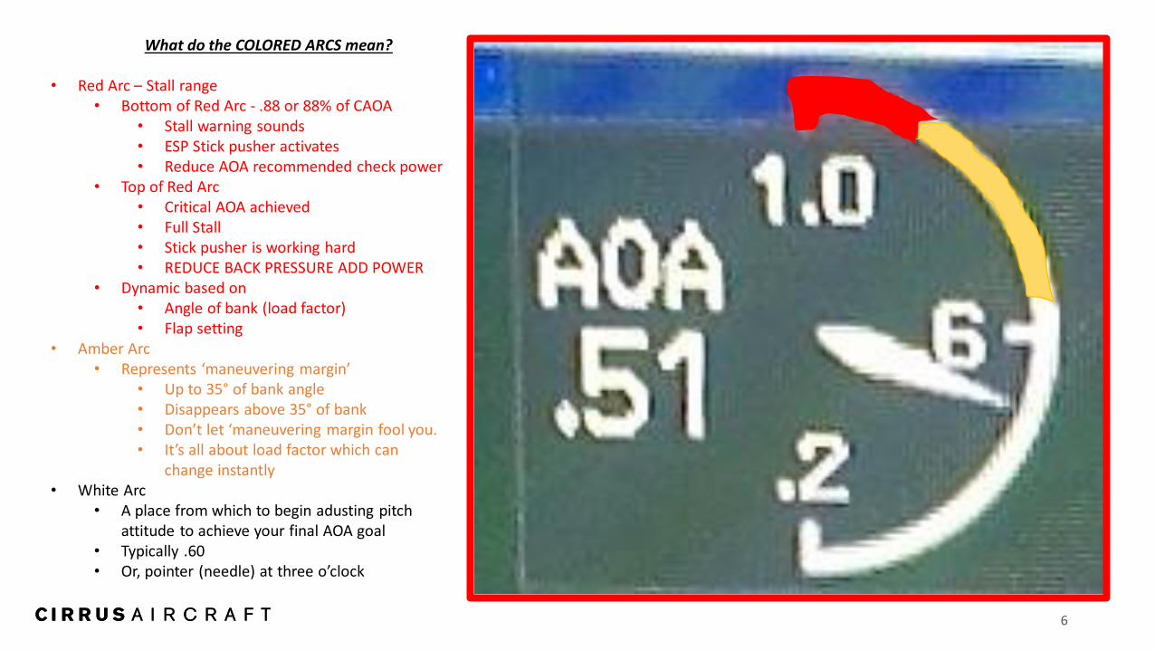
What do the COLORED ARCS mean? • Red Arc – Stall range
• Bottom of Red Arc - .88 or 88% of CAOA • Stall warning sounds • ESP Stick pusher activates • Reduce AOA recommended check power
• Top of Red Arc • Critical AOA achieved • Full Stall • Stick pusher is working hard • REDUCE BACK PRESSURE ADD POWER
• Dynamic based on • Angle of bank (load factor) • Flap setting
• Amber Arc • Represents ‘maneuvering margin’
• Up to 35° of bank angle • Disappears above 35° of bank • Don’t let ‘maneuvering margin fool you. • It’s all about load factor which can
change instantly • White Arc
• A place from which to begin adusting pitch attitude to achieve your final AOA goal
• Typically .60 • Or, pointer (needle) at three o’clock
7
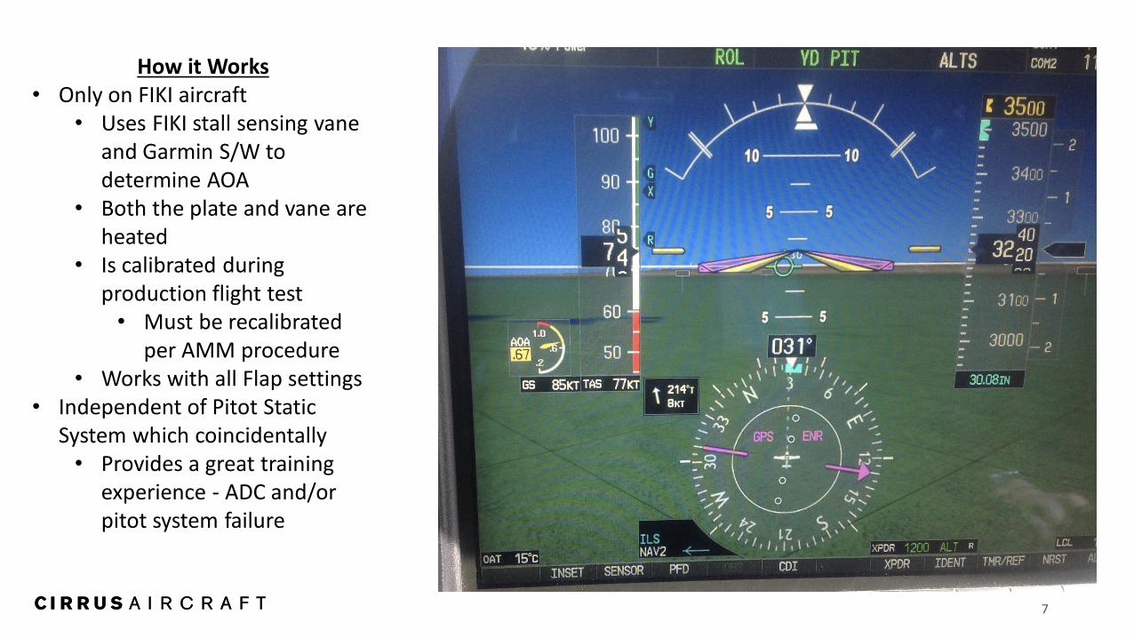
How it Works • Only on FIKI aircraft
• Uses FIKI stall sensing vane and Garmin S/W to determine AOA
• Both the plate and vane are heated
• Is calibrated during production flight test • Must be recalibrated
per AMM procedure • Works with all Flap settings
• Independent of Pitot Static System which coincidentally • Provides a great training
experience - ADC and/or pitot system failure
8
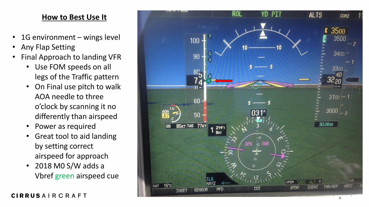
How to Best Use It
• 1G environment – wings level • Any Flap Setting • Final Approach to landing VFR
• Use FOM speeds on all legs of the Traffic pattern
• On Final use pitch to walk AOA needle to three o’clock by scanning it no differently than airspeed
• Power as required • Great tool to aid landing
by setting correct airspeed for approach
• 2018 M0 S/W adds a Vbref green airspeed cue
9
INTERESTING OBSERVATIONS • IF ONE TAKES THE TIME TO WORK WITH AOA ONE MIGHT NOTICE
• BEHAVIOR OF AIRCRAFT AT CONSTANT AOA BUT NOTING AIRSPEED FOR: • DIFFERENT FLAP SETTING • DIFFERENT POWER SETTING • AIRCRAFT ATTITUDE
• BEHAVIOR OF AIRCRAFT AT CONSTANT AIRSPEED BUT NOTING AOA FOR: • DIFFERENT FLAP SETTING • DIFFERENT POWER SETTINGS • AIRCRAFT ATTITUDE
10
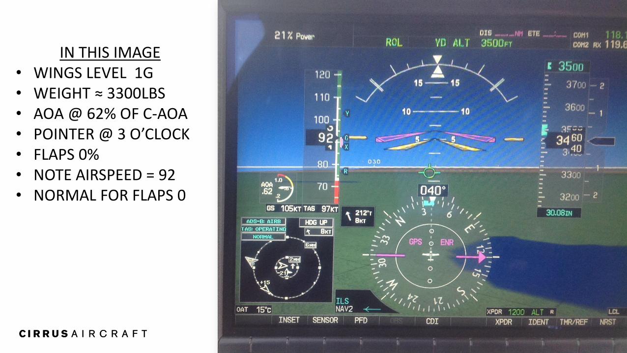
IN THIS IMAGE • WINGS LEVEL 1G • WEIGHT ≈ 3300LBS • AOA @ 62% OF C-AOA • POINTER @ 3 O’CLOCK • FLAPS 0% • NOTE AIRSPEED = 92 • NORMAL FOR FLAPS 0
11
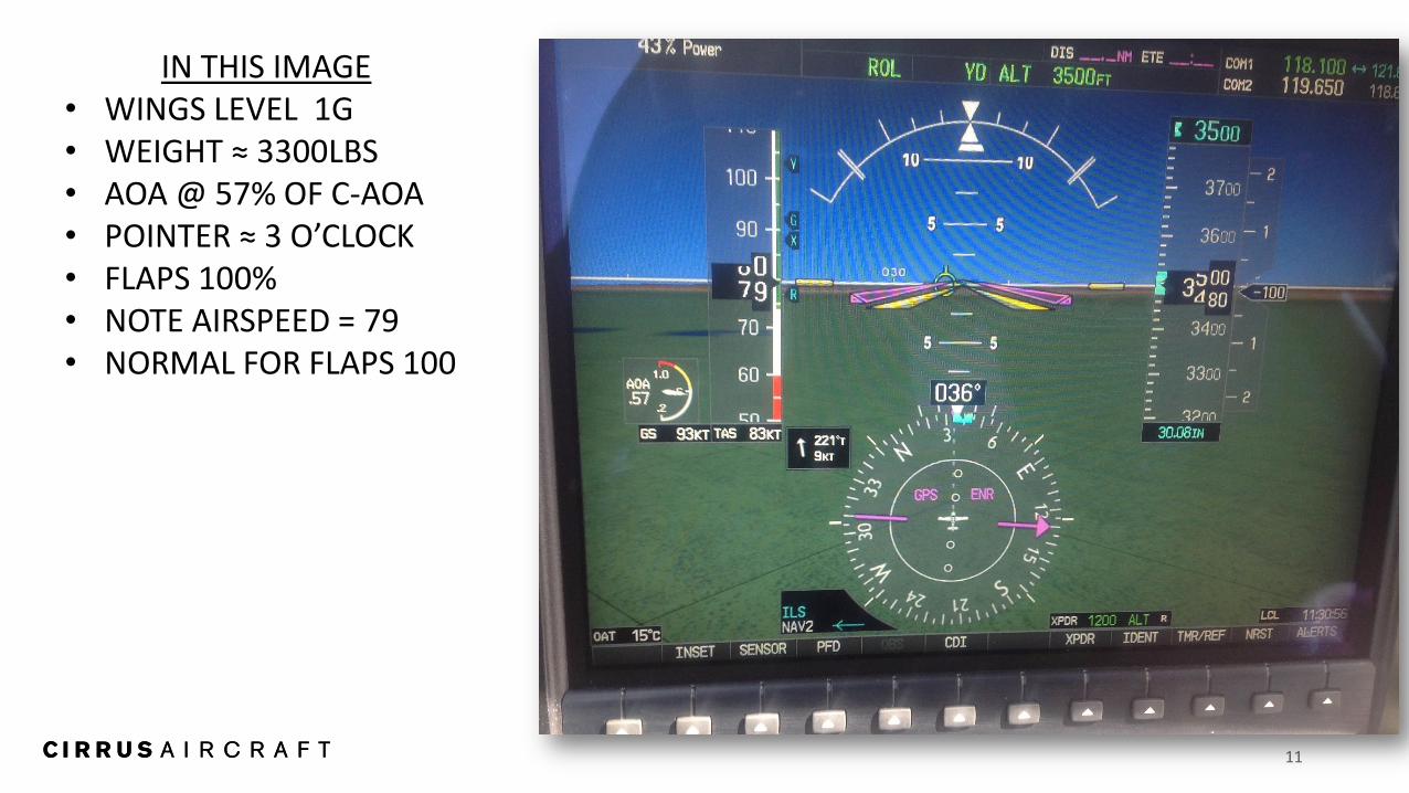
IN THIS IMAGE • WINGS LEVEL 1G • WEIGHT ≈ 3300LBS • AOA @ 57% OF C-AOA • POINTER ≈ 3 O’CLOCK • FLAPS 100% • NOTE AIRSPEED = 79 • NORMAL FOR FLAPS 100
12
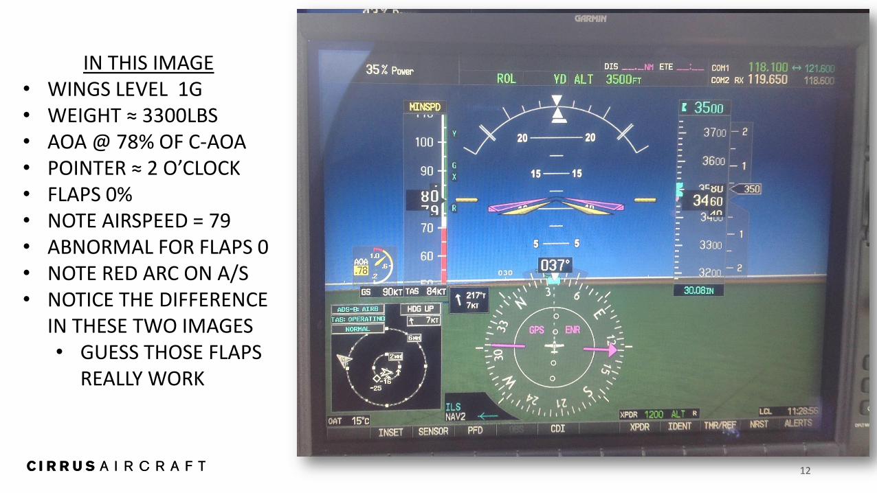
IN THIS IMAGE • WINGS LEVEL 1G • WEIGHT ≈ 3300LBS • AOA @ 78% OF C-AOA • POINTER ≈ 2 O’CLOCK • FLAPS 0% • NOTE AIRSPEED = 79 • ABNORMAL FOR FLAPS 0 • NOTE RED ARC ON A/S • NOTICE THE DIFFERENCE
IN THESE TWO IMAGES • GUESS THOSE FLAPS
REALLY WORK
13
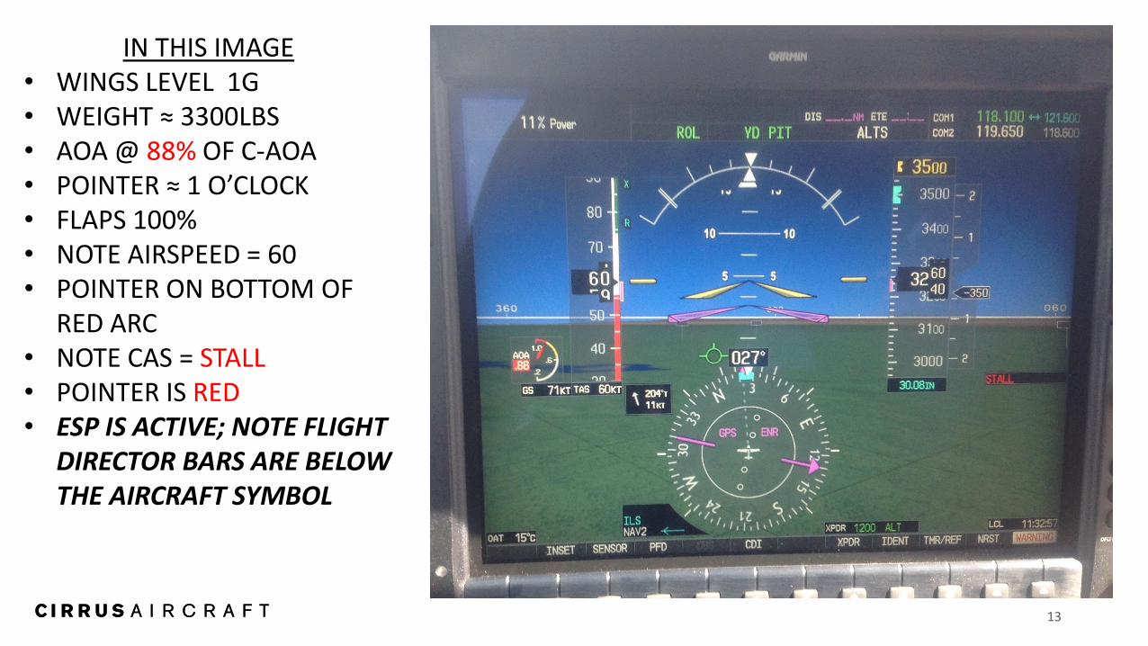
IN THIS IMAGE • WINGS LEVEL 1G • WEIGHT ≈ 3300LBS • AOA @ 88% OF C-AOA • POINTER ≈ 1 O’CLOCK • FLAPS 100% • NOTE AIRSPEED = 60 • POINTER ON BOTTOM OF
RED ARC • NOTE CAS = STALL • POINTER IS RED • ESP IS ACTIVE; NOTE FLIGHT
DIRECTOR BARS ARE BELOW THE AIRCRAFT SYMBOL