Embed Size (px)
Citation preview
Surgical Technique
Ankle Spanning, Metaphyseal/Diaphyseal, Optional Cannulated and Hybrid


Nota BeneThe technique description herein is made available to the healthcare professional to illustrate the author’s suggested treatment for the uncomplicated procedure. In the final analysis, the preferred treatment is that which addresses the needs of the specific patient.
JET-X™ CENTRAL Unilateral External Fixator SystemAnkle Spanning, Metaphyseal/Diaphyseal, Optional Cannulated and HybridSurgical Technique
Contents
Design Features ..........................................................................4
Ankle Spanning Surgical Technique
Rationale ............................................................................. 14
Surgical Technique ............................................................. 15
Metaphyseal/Diaphyseal Surgical Technique
Rationale ............................................................................ 24
Surgical Technique ............................................................ 25
Hybrid Surgical Technique
Rationale ............................................................................ 30
Surgical Technique ............................................................. 31
Important Medical Information ................................................. 34
Catalog Information .................................................................. 36

4
Design Features
Central BodyPart Number: 7105-1041 Short Central Body 7105-1042 Standard Central Body 7105-1043 Long Central Body 7105-1721 Extra Short Central Body
Description:
The Central Body is the main component of the fixator. Complete frames can be easily constructed by snapping a module onto the ball joint connectors on either end. Each Central Body can be compressed or distracted, either acutely or gradually, using the snap-on Compression/Distraction Device. One Allen Wrench tightens the Central Body bolt and each ball joint bolt.
Engineering Data:
Short Central Body
Materials Carbon Fiber Composite High Strength Aluminum Stainless SteelOverall Distracted Length 139mmOverall Compressed Length 119mmTotal Distraction 20mmWrench Needed 6mm Allen Wrench
Standard Central Body
Materials Carbon Fiber Composite High Strength Aluminum Stainless SteelOverall Distracted Length 179mmOverall Compressed Length 139mmTotal Distraction 40mmWrench Needed 6mm Allen Wrench
Long Central Body
Materials Carbon Fiber Composite High Strength Aluminum Stainless SteelOverall Distracted Length 249mmOverall Compressed Length 174mmTotal Distraction 75mmWrench Needed 6mm Allen Wrench
Extra Short Central BodyMaterials Carbon Fiber Composite High Strength Aluminum Stainless SteelOverall Distracted Length 114mmOverall Compressed Length 104mmTotal Distraction 10mmWrench Needed 6mm Allen Wrench
Used with:
Offset Clamp, Straight Clamp, T-Clamp, Ankle Clamp, Ring Adapter, 6mm Allen Wrench, Compression/Distraction Device

5
Offset ClampPart Number: 7105-1722
Description:The Offset Clamp allows placement of half pins anterior-medial in the tibia. There are five pin placement options, which hold 5mm or 6mm half pins. A minimum of two half pins per Offset Clamp is required. Each clamp is spring -loaded to provisionally grip instruments and pins.
Engineering Data: Materials: High Strength Aluminum Stainless SteelTotal Angulation at the Ball 40°Distance Between Outer Pins 46mmDistance From Outer Pins to Center Pin 23mmDistance From Ball to 5mm Half Pins 39.5mmDistance From Ball to 6mm Half Pin 40.0mm
Wrench Needed: 6mm Allen Wrench
Used with:Central Body, 5mm or 6mm Half Pin, Tissue Protector, Drill Sleeve, Trocar, 6mm Allen Wrench
Pin TowerPart Number: 7105-1018
Description:
The Pin Tower allows an additional half pin to be placed oblique to the pin clamps. It will attach to either the T-Clamp or the Straight Clamp.
Engineering Data:
Materials Stainless SteelOverall Height 63.4mmOverall Width 15.9mmWrench Needed 10mm Wrench 6mm Allen WrenchUsed with:
Straight Clamp, T-Clamp, Half Pin, Tissue Protector, Drill Sleeve, Trocar, 10mm Wrench, 6mm Allen Wrench

6
Translating Ankle ClampPart Number: 7105-1054
Description:
The Translating Ankle Clamp is designed to span the ankle for fixation of pilon fractures. The Ankle Clamp offers two options for calcaneal pin placement to best fit a patient’s anatomy. It offers independent coronal and sagittal plane adjustment of the fracture. The removable swivel clamp is lockable and can be switched from left to right ankle configurations. The stem’s radiolucent carbon fiber composite material allows clear visualization of the ankle joint. For stabilization, tightening the center bolt on the hinge clamp prevents plantar flexion and dorsiflexion.
Engineering Data:
Materials Carbon Fiber Composite High Strength Aluminum Stainless SteelDistance Between Outer Pins 58.4mmTotal Angulation at the Ball 40°Diameter of Pin Hole at Center of Rotation of Hinge 1.6mmPlantar Flexion 37°Dorsiflexion 67°Wrench Needed 6mm Allen Wrench
Straight ClampPart Number: 7105-1045
Description:
The Straight Clamp allows placement of half pins in-line with the Central Body. There are five pin placement options, and the clamp holds 5mm or 6mm half pins.
A minimum of two half pins per Straight Clamp is required. Each clamp is spring-loaded to provisionally grip instruments and pins.
Engineering Data:
Materials Carbon Fiber Composite High Strength Aluminum Stainless SteelTotal Angulation at the Ball 40°Length 102.6mmDiameter 37mmDistance from Outer Pins to Center Pin 23mmDistance Between Outer Pins 46mmWrench Needed 6mm Allen Wrench
Used with:
Central Body, Half Pin, Tissue Protector, Drill Sleeve, Trocar, 6mm Allen Wrench
Used with:
Central Body, Half Pin, Tissue Protector, Drill Sleeve, Trocar, 6mm Allen Wrench
7
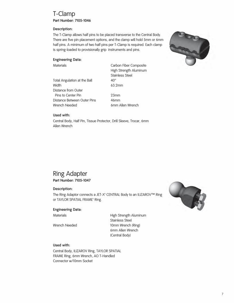
T-ClampPart Number: 7105-1046
Description:
The T-Clamp allows half pins to be placed transverse to the Central Body. There are five pin placement options, and the clamp will hold 5mm or 6mm half pins. A minimum of two half pins per T-Clamp is required. Each clamp is spring-loaded to provisionally grip instruments and pins.
Engineering Data:
Materials Carbon Fiber Composite High Strength Aluminum Stainless SteelTotal Angulation at the Ball 40°Width 63.2mmDistance from Outer Pins to Center Pin 23mmDistance Between Outer Pins 46mmWrench Needed 6mm Allen Wrench
Used with:
Central Body, Half Pin, Tissue Protector, Drill Sleeve, Trocar, 6mm Allen Wrench
Ring AdapterPart Number: 7105-1047
Description:
The Ring Adaptor connects a JET-X™ CENTRAL Body to an ILIZAROVT Ring or TAYLOR SPATIAL FRAME™ Ring.
Engineering Data:
Materials High Strength Aluminum Stainless SteelWrench Needed 10mm Wrench (Ring) 6mm Allen Wrench (Central Body)
Used with:
Central Body, ILIZAROV Ring, TAYLOR SPATIALFRAME Ring, 6mm Wrench, AO T-HandledConnector w/10mm Socket

8
Hybrid StrutPart Number: 7105-1048 Short Hybrid Strut 7105-1049 Long Hybrid Strut
Description:
The Hybrid Strut supports the ring on the fixator in a hybrid application. In a tibial plateau application, the Hybrid Strut attaches distally to the Straight Clamp and proximally to the ring.
Engineering Data:
Short Hybrid Strut
Materials High Strength Aluminum Stainless SteelTotal Telescoping Movement 57.2mmWrench Needed 10mm Wrench 6mm Allen Wrench
Used with:
Straight Clamp, ILIZAROVT Ring, TAYLOR SPATIAL FRAME™ Ring, 10mm Wrench, 6mm Allen Wrench
AO T-Handle Connector with 10mm SocketPart Number: 7106-3001
Description:
The AO T-Handle Connector with 10mm Socket is a dual-purpose instrument. The AO Connector allows the manual insertion of half pins with the T-Handle, while the 10mm Socket provides compatibility with ILIZAROV Composite Rings in hybrid applications.
Engineering Data:
Material Stainless SteelOverall Size (Top of Handle to End of Socket) 91.4mmHandle Size 101.6mm x 31.2mmConnection AO Connection 10mm SocketUsed with:Ring Adaptor, 5mm Half Pin, 10mm Connector
Long Hybrid Strut
Materials High Strength Aluminum Stainless SteelTotal Telescoping Movement 108mmWrench Needed 10mm Wrench 6mm Allen Wrench

9
6mm Allen WrenchPart Number: 7105-3006
Description:
The 6mm Allen Wrench is the only instrumentneeded to tighten all JET-X™ CENTRAL modules.
Engineering Data:
Material Stainless SteelOverall Length 190mm
Used with:
Central Body, Straight Clamp, T-Clamp, Trauma Ankle Clamp, Pin Tower, Compression/Distraction Device
Compression/Distraction DevicePart Number: 7105-1051 Short Central Body 7105-1052 Standard Central Body 7105-1053 Long Central Body 7105-1721 Extra Short Central Body
Description:
The Compression/Distraction Device compresses or distracts the Central Body. It can be added to the fixator before, during or after surgery. Posts on both ends of the Device simply plug into the mounting holes on the end caps of the Central Body.
Engineering Data:
Short C/D Device
Materials Stainless Steel Teflon®
Overall Distracted Length 110mmOverall Compressed Length 90mmTotal Distraction 20mmWrench Needed 6mm Allen Wrench
Standard C/D Device
Materials Stainless Steel TeflonOverall Distracted Length 149.5mmOverall Compressed Length 109.5mmTotal Distraction 40mmWrench Needed 6mm Allen Wrench
Used with:
Central Body, 6mm Allen Wrench
Long C/D Device
Materials Stainless Steel TeflonOverall Distracted Length 219.5mmOverall Compressed Length 144.5mmTotal Distraction 75mmWrench Needed 6mm Allen Wrench
Extra Short C/D Device
Materials Stainless Steel TeflonOverall Distracted Length 86mmOverall Compressed Length 76mmTotal Distraction 10mmWrench Needed 6mm Allen Wrench

10
10mm Ratchet WrenchPart Number: 7106-3003
Description:
The 10mm Ratchet Wrench may be used with any 10mm connector.
Engineering Data:
Material Stainless SteelLength 159mmConnection 10mm Open-end 10mm Closed-endUsed with:
Ring Adaptor, Hybrid Strut, Pin Tower
3.5mm Graduated Drill with AO ConnectorPart Number: 7106-3006
Description:
The 3.5mm Drill is used to pre-drill for 5mm half pins.
Engineering Data:
Material Stainless SteelLength 260.4mmDiameter 3.5mmConnection AO Connection
Used with:
Straight Clamp, T-Clamp, Ankle Clamp, Pin Tower, Tissue Protector, Drill Sleeve, Half Pin

11
3.5mm/1.6mm Graduated Cannulated Drill with AO ConnectorPart Number: 7106-3013
Description:
The 3.5mm/1.6mm Drill is used to pre-drill over a 1.6mm wire for 5mm Cannulated Half Pins.
Engineering Data:
Material Stainless SteelOverall Length 165.1mmDiameter 3.5mmCannulation 1.6mmConnection AO Connection
Used with:
Ankle Clamp, 1.6mm Wire, 1.6mm Wire Guide, Cannulated Pin Tissue Protector, Cannulated Pin Drill Sleeve, Cannulated Half Pin
Trauma Ankle Clamp Drill GuidePart Number: 7106-3014
Description:
The Trauma Ankle Clamp Drill Guide assists in pin placement for talar and calcaneal pins.
Engineering Data:
Materials Stainless Steel Aluminum Ultem®
Distance Between Outer Pins 58.4mmDiameter of Pin Hole at Center ofRotation of Guide 1.6mm
Used with:
1.6mm Wire, 5mm Tissue Protector, Trocar, 3.5mm Drill Sleeve, 5mm Half Pin, Trauma Ankle Clamp

12
5mm x 40mm x 1.6mmCannulated Half PinPart Number: 7106-5405
Description:
The 5mm Cannulated Half Pin is used in conjunction with a 1.6mm Wire for precise placement in the talar neck.
Engineering Data:
Material Stainless SteelOverall Length 175mmThread Length 40mmDiameter 5mmCannulation 1.6mmConnection AO Connection
Used with:
Ankle Clamp, 1.6mm Wire, 1.6mm Wire Guide,Cannulated Pin Tissue Protector, Cannulated PinDrill Sleeve, Cannulated Drill

13
Ankle Spanning Surgical Technique

14
Rationale
The JET-X™ CENTRAL Unilateral External Fixator is used to rapidly stabilize open and/or unstable fractures, to secure osteotomies and for fracture fixation (open and closed). It is especially useful in cases where the soft tissue damage prevents incisions and soft tissue recovery is needed.
Indications for the JET-X CENTRAL Ankle Fixator
1. The first part of a two-stage treatment protocol for complex pilon fractures (open reduction and internal fixation [ORIF] of the fibula and placement of an external fixation until soft tissue healing occurs to allow ORIF of the distal tibia).
2. The definitive treatment of ankle and plafond fractures that cannot be treated by ORIF (ie severely damaged soft tissue or open fractures).
JET-X CENTRAL Modular Quick Assembly
The modular components of the JET-X CENTRAL Unilateral External Fixation System can be quickly combined to construct a simple yet versatile ankle fixation frame. Simply snap-click the Offset Clamp and Ankle Clamp modules into the connecting ports at each end of a Central Body (short, standard, long or extra short).
Relevant Anatomy
Care must be taken to avoid neurovascular structures and intraarticular penetration. Shaded areas: Medial talar and medial calcaneal safe pin zones.

15
JET-X™ CENTRAL Unilateral External Fixator Ankle Spanning Surgical Technique
Placement of Ankle PinsStep One
Make a stab wound in the skin one finger breadth inferior and one finger breadth anterior to the medial malleolus parallel to the talus.
Step Two
Bluntly dissect down to the neck of the talus. Place 3.5mm drill guide into 5mm tissue protector, insert trocar and push to bone to find center of talar neck.

16
Placement of Ankle Pins (Cont.)
Step Three
Insert the 3.5mm graduated drill through the 3.5mm drill guide and tissue protector, with the C-arm coming from the ipsilateral side of the injury in the Mortise view (15° internal rotation from the AP) drill across the talus parallel to the dome.
Step Four
Verify drill placement on lateral C-arm (A). Remove 3.5mm drill and drill guide. Insert 5mm half pin through the 5mm tissue protector into the talus achieving bicortical purchase (B).
Option: Manually insert JET-X™ Half Pins using the T-handle connector. Attach half pin to the T-handle connector by pulling back on the gold locking collar.
Note: JET-X Half Pins are self-drilling and self-tapping, and may be inserted under power without pre-drilling.)
A
B

17
Placement of Ankle Pins (Cont.)Step Five
Place the ankle clamp drill guide over the talar half pin, and then place the 5mm tissue protector over the talar half pin.
Step Six
Place a 5mm tissue protector and 3.5mm drill guide in the desired calcaneal slot, and line up the center of the ankle clamp drill guide at the subtalar joint. Make a stab wound and bluntly dissect to bone. Place the 5mm tissue protector and 3.5mm drill guide to bone. Insert self-drilling half pin or pre-drilled half pin. Remove ankle clamp drill guide.

18
Apply FixatorStep Seven
Ensure the JET-X™ CENTRAL Body is extended at least 1cm to allow compression or distraction. Adjust fixator to appropriate length via telescoping Central Body. Lock Central Body telescoping lock using the 6mm Allen Wrench.
Place the fixator over the talar and calcaneal pins. Tighten the anterior and posterior bolts on the ankle clamp with the 6mm Allen Wrench.
Insertion of Proximal PinsStep Eight
Provisionally tighten the ball joints of the fixator using the 6mm Allen Wrench for added stability in placing the tibial half pins.
Use the pin clamp as a template. The spring-loaded pin clamp will provisionally hold 5mm tissue protectors in place. Make a stab incision and bluntly dissect to the anteromedial face of the tibia. Insert self-drilling or pre-drilled half pins through the 5mm tissue protector. (See Step 3 for pre-drilling technique.) Remove the tissue protectors and tighten the pin clamps around the half pins. Leave 2cm between fixator and skin for swelling. Pins can be cut at the fixator level and pin caps applied.
Supplementary half pins can be used for additional stability. (See Pin Tower on Page 20.)
19
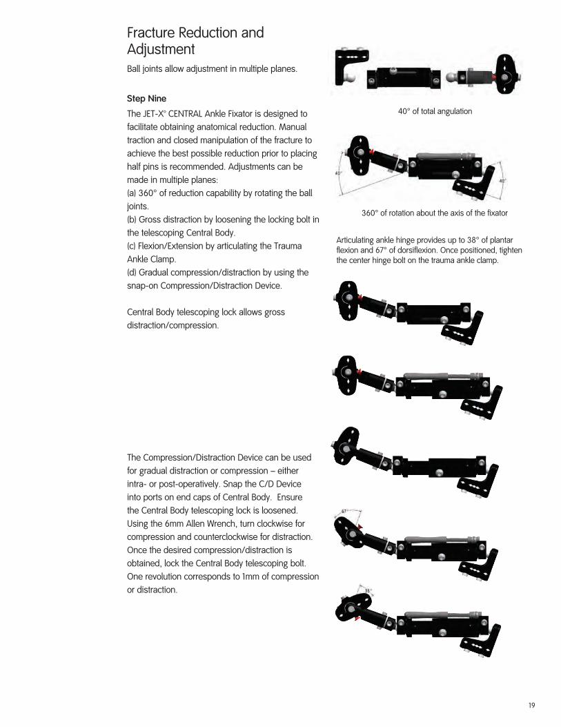
Fracture Reduction and AdjustmentBall joints allow adjustment in multiple planes.
Step Nine
The JET-X™ CENTRAL Ankle Fixator is designed to facilitate obtaining anatomical reduction. Manual traction and closed manipulation of the fracture to achieve the best possible reduction prior to placing half pins is recommended. Adjustments can be made in multiple planes: (a) 360° of reduction capability by rotating the ball joints. (b) Gross distraction by loosening the locking bolt in the telescoping Central Body. (c) Flexion/Extension by articulating the Trauma Ankle Clamp. (d) Gradual compression/distraction by using the snap-on Compression/Distraction Device.
Central Body telescoping lock allows gross distraction/compression.
The Compression/Distraction Device can be used for gradual distraction or compression – either intra- or post-operatively. Snap the C/D Device into ports on end caps of Central Body. Ensure the Central Body telescoping lock is loosened. Using the 6mm Allen Wrench, turn clockwise for compression and counterclockwise for distraction. Once the desired compression/distraction is obtained, lock the Central Body telescoping bolt. One revolution corresponds to 1mm of compression or distraction.
40° of total angulation
360° of rotation about the axis of the fixator
Articulating ankle hinge provides up to 38° of plantar flexion and 67° of dorsiflexion. Once positioned, tighten the center hinge bolt on the trauma ankle clamp.

20
Fracture Reduction and Adjustment (Cont.)Each ball joint on the JET-X™ CENTRAL Unilateral External Fixator provides 360° of rotation about the axis of the fixator, within 40° of angulation, for smooth anatomical reduction.
Final Fixator TighteningStep Ten
After reduction is achieved, ensure the pin clamp bolts, ball joint bolts, telescoping lock bolt and hinge bolt are all securely tightened with the 6mm Allen Wrench. No torque wrench is necessary. Tighten the ball joint bolt until the gap in the housing is completely closed.
Pin TowerThe Pin Tower allows placement of a half pin convergent to those placed through a Straight or T-clamp. Attach the Pin Tower to a clamp by threading the base of the Pin Tower into the threaded hole located on top of the T-clamp or on the side of the Straight Clamp. The Pin Tower base should not be tightened at this point, and the hinge bolt on the Pin Tower should be loose. Place the 5mm tissue protector through the Pin Tower clamp, verify location of pin insertion and insert the half pin.
Note: JET-X Half Pins are self-drilling, but could be pre-drilled if desired.
Tighten the base of the Pin Tower with a 10mm wrench. Tighten the hinge joint and pin clamp bolts using the hex wrench.

21
Optional Cannulated Technique for Talar Pin PlacementStep One
Make a stab wound in the skin one finger breadth inferior and one finger breadth anterior to the medial malleolus parallel to the talus.
Step Two
Bluntly dissect down to the neck of the talus. Use the 5mm cannulated pin tissue protector; insert the 3.5mm cannulated pin drill sleeve with the inserted trocar to find the center of the talar neck. Remove the trocar. Insert the 1.6mm wire guide.
Step Three
With the C-arm coming from the ipsilateral side of the injury in the Mortise view (15° internal rotation from the AP view) drill the 1.6mm guide wire across the talus parallel to the dome.

22
Optional Cannulated Technique for Talar Pin Placement (Cont.)Step Four
Verify guide wire placement on lateral C-arm. Remove 1.6mm wire guide and the 3.5mm cannulated pin drill sleeve. Drill the 5mm cannulated half pin over the guide wire into the talus achieving bicortical purchase.
Option: The talar pin placement may be pre-drilled using the 3.5/1.6mm graduated cannulated drill.)
Step Five
Place the ankle clamp drill guide over the talar half pin, and then place the 5mm tissue protector over the talar half pin. (See Step Six, Ankle Spanning Technique page 17.)
Note: JET-X™ Half Pins have a tapered minor diameter and a constant major diameter which maintains excellent cortical contact even when pin is backed out to achieve optimal position.
23
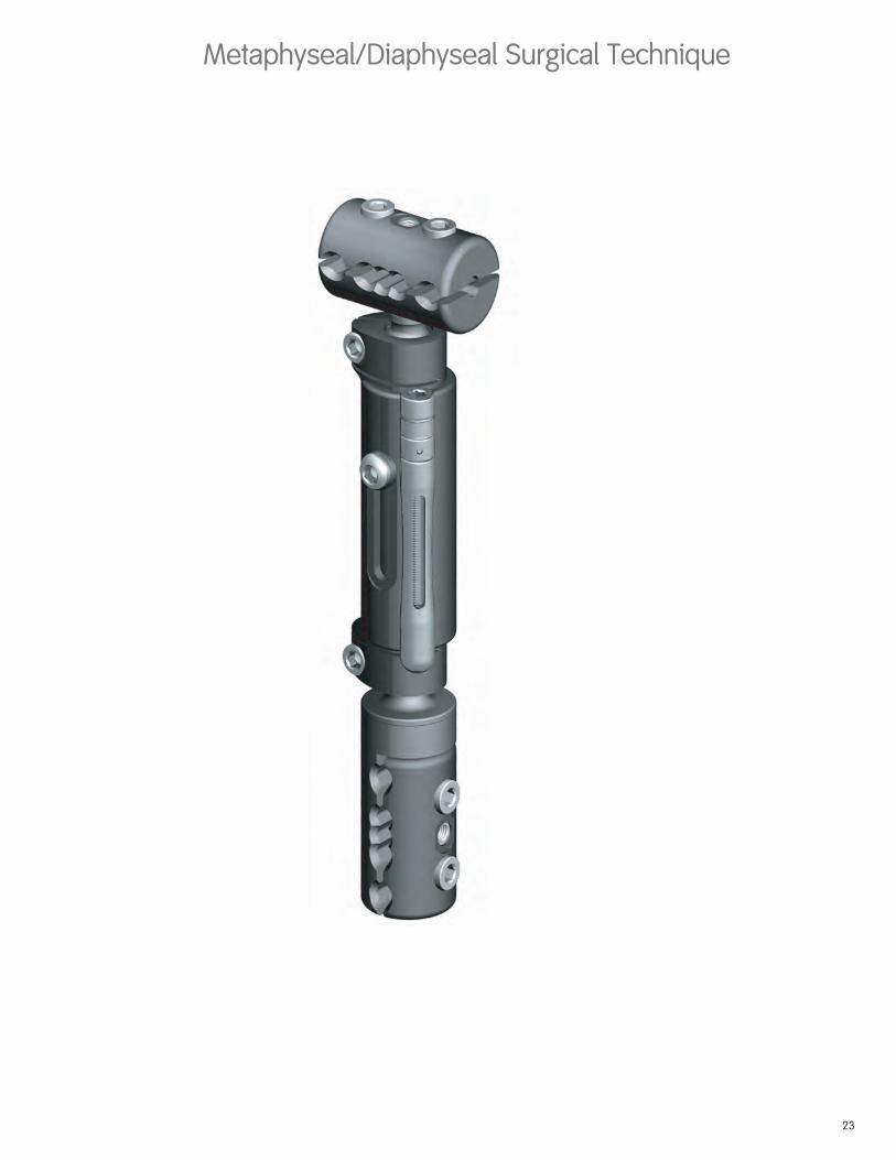
Metaphyseal/Diaphyseal Surgical Technique

24
Rationale
Preoperative planning helps to ensure that the optimal fixator will be constructed for each case as dictated by the soft tissue injury and fracture pattern. It is important to first obtain gross manual alignment of the fracture.

25
JET-X™ CENTRAL Unilateral External Fixator Metaphyseal/Diaphyseal Surgical Technique
General Half Pin ApplicationStep One
With any diaphyseal fracture, prior reduction–especially rotation–is preferred. Place two half pins on one side of the fracture, preferably the shorter segment. Use the spring-loaded pin clamps to hold the 5mm tissue protectors in position.
Step Two
Make a stab skin incision, bluntly dissect to bone, and place the 5mm tissue protector to bone.
Step Three
Insert the 5mm self-drilling half pins. (Optionally, pre-drill with a 3.5mm drill.) Once the first pin is placed, leave the tissue protector guide in place and insert the second half pin in a similar fashion.
Step Four
Once the second half pin is placed, remove the two 5mm tissue protectors, and tighten the pin clamp.
Assemble the fixator: Snap lock selected pin clamps into selected Central Body ensuring that the Central Body of the fixator is lengthened at least 1cm for compression or distraction.
Step Five
Slightly tightening the ball joint using the 6mm Allen Wrench gives stability to the frame for placement of the second set of half pins.

26
General Half Pin Application(Cont.)Step Six
Use the second pin clamp as a template for pin placement. Insert the two half pins through the pin clamp on the opposite side of the fracture.
Step Seven
Tighten the second pin clamp using the 6mm Allen Wrench. Make final adjustments using ball joints and Central Body translation. Usually leave 2cm between the skin and fixator for swelling.
Step Eight
Tighten all bolts using the 6mm Allen Wrench. Ball joints are sufficiently tightened when the gap in the housing is completely closed.
Step Nine
The JET-X™ CENTRAL Unilateral External Fixator is designed to facilitate obtaining anatomical reduction. Manual traction and closed manipulation of the fracture to achieve the best possible reduction prior to placing half pins is recommended. Adjustments can be made in multiple planes: (a) 360° of reduction capability by rotating the ball joints. (b) Gross distraction by loosening the locking bolt in the telescoping Central Body. (c) Gradual compression/distraction by using the snap-on Compression/Distraction Device. (See Page 9 for diagram.)

27
JET-X™ CENTRAL Unilateral External Fixator ApplicationsTibial Shaft Frame
Fixator is usually placed along the medial face of the tibia avoiding the muscles of the tibia.
Additional half pins may be used for stability.
Proximal or Distal Tibia Metaphyseal Fracture
Placement of the T-clamp proximal anteromedial.
28
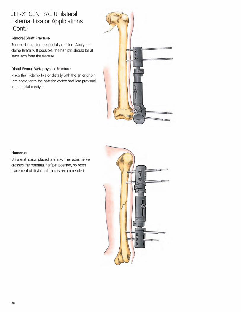
JET-X™ CENTRAL Unilateral External Fixator Applications (Cont.)Femoral Shaft Fracture
Reduce the fracture, especially rotation. Apply the clamp laterally. If possible, the half pin should be at least 3cm from the fracture.
Distal Femur Metaphyseal Fracture
Place the T-clamp fixator distally with the anterior pin 1cm posterior to the anterior cortex and 1cm proximal to the distal condyle.
Humerus
Unilateral fixator placed laterally. The radial nerve crosses the potential half pin position, so open placement at distal half pins is recommended.

29
Hybrid Surgical Technique

30
Rationale
The JET-X™ CENTRAL Unilateral External Fixator can easily accommodate either ILIZAROVT or TAYLOR SPATIAL FRAME™ rings using the snap-fit Hybrid Ring Adaptor.
Indications
Metaphyseal and articular fractures in proximal and distal tibia and distal femur.

31
Proximal Tibia
Femur Anterior
JET-X™ CENTRAL Unilateral External Fixator Hybrid Surgical Technique
General TechniqueStep One
Selection of either a full ring (distal tibia) and/or 5/8 ring (distal femur; proximal tibia) is preferred. The transfixing wire closest to the joint is inserted first, parallel to the joint surface. Olive wires or smooth wires can be placed. (Olive wires allow translation correction along the axis of the wire). The initial reference wire is tensioned using the dynametric wire tensioner to the full ring (130 kg) or 5/8 ring(110 kg).
The proper wire insertion technique is to push the wire through the soft tissue and drill through the bone using a moist lap to hold the wire during insertion. Use the C-arm to ensure the wire is parallel to the joint. Avoid the joint capsule (in the knee, 14mm below the joint laterally and 9mm below the joint medially).
Insert a second transfixing wire on the opposite side of the ring ensuring the ring remains parallel to the joint. Additional wires and half pins (using Rancho cubes) may be added for stability.
Distal Tibia

32
Fixator Quick AssemblyStep Two
Select a Central Body (short, standard, long or extra short). Snap Hybrid Ring Adaptor into one end of the Central Body and Straight Clamp into the other end.
Step Three
Using a 10mm wrench, attach the Hybrid Adaptor to the ring with the 2 bolts. The ball joint in the Hybrid Adaptor facilitates reduction and optimal pin placement by providing 20° of adjustment in any direction. Connect the 5/8 ring to the other ring using threaded rods and nuts.
Step Four
Select short or long Hybrid Struts. Insert the two mounting pins located on the hybrid strut-mounting bar into the central pin slots of the Straight Clamp.
33
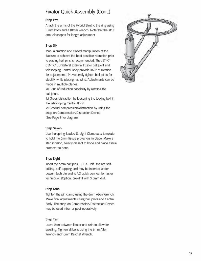
Fixator Quick Assembly (Cont.)Step Five
Attach the arms of the Hybrid Strut to the ring using 10mm bolts and a 10mm wrench. Note that the strut arm telescopes for length adjustment.
Step Six
Manual traction and closed manipulation of the fracture to achieve the best possible reduction prior to placing half pins is recommended. The JET-X™ CENTRAL Unilateral External Fixator ball joint and telescoping Central Body provide 360° of rotation for adjustments. Provisionally tighten ball joints for stability while placing half pins. Adjustments can be made in multiple planes:(a) 360° of reduction capability by rotating theball joints.(b) Gross distraction by loosening the locking bolt inthe telescoping Central Body.(c) Gradual compression/distraction by using thesnap-on Compression/Distraction Device.(See Page 9 for diagram.)
Step Seven
Use the spring-loaded Straight Clamp as a template to hold the 5mm tissue protectors in place. Make a stab incision, bluntly dissect to bone and place tissue protector to bone.
Step Eight
Insert the 5mm half pins. (JET-X Half Pins are self-drilling, self-tapping and may be inserted under power. Each pin end is AO quick connect for faster technique.) (Option: pre-drill with 3.5mm drill.)
Step Nine
Tighten the pin clamp using the 6mm Allen Wrench. Make final adjustments using ball joints and Central Body. The snap-on Compression/Distraction Device may be used intra- or post-operatively.
Step Ten
Leave 2cm between fixator and skin to allow for swelling. Tighten all bolts using the 6mm Allen Wrench and 10mm Ratchet Wrench.

34
Important Medical InformationExternal Fixation Systems
SPECIAL NOTEExternal fixation should be used only under the directions of physicians who have a thorough knowledge of the anatomy, physiology and surgical principles involved. Physicians are strongly encouraged to obtain instruction from experienced clinicians or to observe surgical application of the apparatus prior to its initial use.
DESCRIPTIONExternal Fixation Systems consist of various components used to build constructs to treat the indications listed below. External Fixation Systems are modular, therefore, different frame configurations are possible. An individualized configuration should be designed for each case to suit the specific application. Refer to supporting instruction information provided by Smith & Nephew or component information assembly instructions, and surgical techniques for each individual external fixation system. All External Fixation System components are designed for single use only.
Unless outlined in supporting instructional information, each External Fixation System is designed as a system and does not allow the substitution of components from other systems or manufacturers.
External Fixation Systems are made from various types of metal, plastic, and composite materials. The component material is provided on the outside carton label.
The COMPASS™ Universal Hinge is used with the ILIZAROVTM External Fixator to control distraction and rotation of an injured joint to regain, maintain, or increase the range of motion of the joint. It utilizes circular frame and half-pin fixation techniques and procedures for placement of the device. The device is intended to be centered on the axis of rotation. The device allows some adjustability to permit adjustment on the axis. Please refer to the surgical technique for complete details of the recommended procedures.
The TAYLOR SPATIAL FRAME™ Fixator utilizes computer software to recommend adjustments to the fixation frame based on surgeon-derived measurements and examination.
INDICATIONS1. Post-Traumatic joint contracture which has resulted in loss of range of motion (not applicable for
Smith & Nephew Rail System) 2. Fractures and disease which generally may result in joint contractures or loss of range of motion
and fractures requiring distraction3. Open and closed fracture fixation4. Pseudoarthrosis of long bones5. Limb lengthening by epiphyseal or metaphyseal distraction (not applicable for COMPASS
Universal Hinge or JET-X™ Fixator)6. Correction of bony or soft tissue deformities (not applicable for COMPASS Universal Hinge)7. Correction of segmental bony or soft tissue defects8. Joint arthrodesis (not applicable for Smith & Nephew Rail System)9. Infected fractures or nonunions10. Mini external fixator systems are indicated for the management of comminuted intra-articular
fractures of the distal radius (not applicable for Smith & Nephew Rail System)11. Calandruccio devices are indicated for arthrodesis of the ankle or subtalar joints, as well as
some select fractures, nonunion, or osteotomy of the distal tibia; and acute transverse fractures or nonunion of the distal tibia (not applicable for Smith & Nephew Rail System)
CONTRAINDICATIONSExternal fixation devices are contraindicated for use in uncooperative or mentally incompetent patients who are unable to follow the postoperative regimen.
Calandruccio devices are also contraindicated for fractures that will most likely heal satisfactorily with noninvasive conservative management, either casting or cast bracing without loss of joint function. Other contraindications include fractures or nonunions which do not permit multiple pin fixation in the coronal plane and patients with medical problems that require weight-bearing on the extremity.
WARNINGS1. The correct selection of device components is extremely important. The appropriate type and
size should be selected for the patient based on injury, weight, compliance, etc.2. Preliminary frame assembly is recommended to reduce operative times and to assure an
adequate supply of components prior to surgery.3. Intraoperative fracture or instrument breakage can occur. Instruments which have been used
extensively or with excessive force are susceptible to fracture. Examine all instruments for wear and damage prior to surgery. Replace where necessary. Single use devices should not be reused due to risks of breakage, failure or patient infection.
4. Correction of varus, valgus, procurvatum, and recurvatum movement of limb segments during distraction should be planned preoperatively by selecting an appropriate prophylactic ring tilt and strategically positioning wires with stoppers, fulcrums, half pins, and hinges.
5. Wire and pin placement requires strict anatomical consideration to avoid damage to nerves, muscles, tendons, and vessels. Wires should be gently pushed through soft tissue, not drilled, to reduce the possibility of injury.
6. Wire drilling through the bone should be done slowly to avoid heat necrosis of surrounding tissues and bone.
7. Use caution when handling the sharp tips of wires. The tip of the wire should be held when clipped. Eye protection is recommended for operating room personnel.
8. Pin/wire site care is crucial in reducing infections.9. Periodic postoperative follow-up and radiographs are recommended during the distraction phase.
PRECAUTIONS1. Use extreme care in handling and storing components. Cutting, bending, or scratching the
surface of components can reduce the strength and fatigue life of the device. Any components damaged during the course of the treatment should be replaced. Wire bending can be avoided by using various types of washers to build the ring to the wire.
2. Surgical technique information is available upon request. The surgeon should be familiar with the devices, instruments and surgical technique prior to surgery.
3. Unless specified, only components from the same system should be used together. Refer to supporting instruction information for details on each external system.
4. Proper fixation and assembly of components are essential. All wires and miscellaneous parts should be securely fastened with the appropriate instrument. Wires should be tensioned as specified in product literature.
5. The proper wire diameter should be used to ensure sufficient wire strength and to maintain appropriate axial stiffness of the apparatus. The 1.8 mm wires are usually recommended for the tibia and femur in normal adults, while the 1.5 mm wires are usually recommended for the upper limbs and pediatric lower limb applications.
6. The diameter of the rings, assembled half rings or frames, are recommended to be about 4cm larger than the maximum diameter of the operated limb segment to accommodate swelling.
7. Wire/pin security in bone, wire tension, and device frame integrity should be routinely checked. The gap at a fracture site should be reassessed during healing. Adjustments should be made as necessary.
8. The patient should be instructed to report any adverse or unanticipated effects to the physician as soon as possible and should also be advised of the distraction and adjustment requirement.
9. Preoperative planning for the TAYLOR SPATIAL FRAME Fixator requires special software and programs. Accurate inputs are critical for accurate results. Verify and double check all input parameters. The computer program should be run twice to verify that the parameters have been correctly entered into the software. The TAYLOR SPATIAL FRAME Fixator can be used as a template to compare the adjusted frame to the deformity to verify fit. Output of strut lengths from the program can exceed any strut length for a particular preassembled frame. If this occurs, refer to Surgical Technique and Instruction Manuals.
10. Intraoperative placement of the TAYLOR SPATIAL FRAME Fixator according to preoperative plans is imperative to achieve predetermined results. If intraoperative conditions require a change to frame placement (eccentricity) or size (parameters), new strut lengths should be calculated by entering the new inputs into the program. Small changes may affect accuracy of outcome.
11. Touch down weight bearing may be allowed postoperatively. Weight bearing may be increased as the callus thickens.
12. For patients with Calandruccio devices, postoperative care and physical therapy should be structured to prevent weight bearing on the operated leg until sufficient healing is evident on the x-ray.
13. MRI Information
JET-X Unilateral External Fixator System components are labeled MR Conditional according to the terminology specified in ASTM F2503-05, Standard Practice for Marking Medical Devices and Other Items for Safety in the Magnetic Resonance Environment.
Non-clinical testing demonstrated that the JET-X Unilateral External Fixator System components, when used in the specific configuration stated herein, are MR Conditional. Representative JET-X Unilateral External Fixator System components used in a typical construct included bar/pin clamps, multi-pin clamps, composite bars and metal half pins. A patient with the JET-X Unilateral External Fixator System can be scanned safely immediately after placement under the following conditions:
• Static magnetic field of 1.5-Tesla with the center of the JET-X Unilateral External Fixator System frame positioned at least 30cm from the isocenter of the bore
• Static magnetic field of 3.0-Tesla with no restriction for the position of the JET-X Unilateral External Fixator System frame
• Highest spatial gradient magnetic field of 720-Gauss/cm or less
• Maximum MR system reported, whole-body-averaged specific absorption rate (SAR) of 2 W/kg, (i.e. normal operating mode only).
Note: In non-clinical testing, a JET-X Unilateral External Fixator System construct (comprised of 4 bar/pin clamps, 4 stainless steel half pins and a 350mm long composite bar) was combined with a JET-X Unilateral External Fixator System Knee Spanning fixator construct (comprised of 4 bar/pin clamps, 3 bar/bar clamps, 1 multiple pin clamp, 4 stainless steel half pins and 3 composite bars ranging from 150mm to 600mm in length) to produce the worst-case “conduction loop”. In this non-clinical testing, the maximum observed heating was 19°C for 1.5T and 5.7°C for 3.0T. Because higher in vivo heating could be possible, close patient monitoring and communication with the patient during scanning is required.
Patients may be safely scanned in the MRI chamber when the center of the JET-X Unilateral External Fixator System frame is positioned at least 30cm from the isocenter/longitudinal center of the bore of the magnet. To maintain this distance, patients may need to be positioned differently dependent on the anatomic placement of the JET-X Bar fixator frame (e.g. on the Upper or Lower extremity). All other Smith & Nephew External Fixation Systems do not claim MRI safety or conditionality and no testing has been performed to evaluate the products for safety and compatibility in the MR environment. The External Fixation Systems have not been tested for heating or migration in the MR environment.
Artifact InformationMR image quality may be compromised if the area of interest is in the exact same area or relatively close to the position of the JET-X Unilateral External Fixator System construct. Therefore, it may be

35
necessary to optimize MR imaging parameters in order to compensate for the presence of the JET-X Unilateral External Fixator System construct.
Representative components used to assemble a typical JET-X Unilateral External Fixator System construct have been evaluated in the MRI chamber. Artifact test results are summarized below. Overall, artifacts created by JET-X Unilateral External Fixator System components may present problems if the MR imaging area of interest is in or near the area where the JET-X Unilateral External Fixator System construct is located. See Table 1 below for artifact information.
Table 1 - Summary of MRI Artifacts @ 3-Tesla for Components of the JET-X Unilateral External Fixator System
Artifact Information
JET-X CENTRAL-to-Pin Clamp (51mm x 32mm x 25mm)
Pulse Sequence T1 - SE T1 - SE GRE GRE
Signal Void Size 13,652 mm2 11,555 mm2 21,494 mm2 21,809 mm2
Imaging Plane Parallel (long axis) Perpendicular (short axis)
Parallel (long axis) Perpendicular (short axis)
JET-X 350mm Composite Bar (10.5mm diameter x 350mm long)
Pulse Sequence T1 - SE T1 - SE GRE GRE
Signal Void Size 1,726 mm2 109 mm2 1,823 mm2 112 mm2
Imaging Plane Parallel (long axis) Perpendicular (short axis)
Parallel (long axis) Perpendicular (short axis)
JET-X Long Titanium Nitride Half Pin (6mm diameter x 232mm long)
Pulse Sequence T1 - SE T1 - SE GRE GRE
Signal Void Size 6,311 mm2 2,446 mm2 12,073 mm2 6,115 mm2
Imaging Plane Parallel (long axis) Perpendicular (short axis)
Parallel (long axis) Perpendicular (short axis)
JET-X Multi-Pin Clamp (102mm x 32mm x 25mm)
Pulse Sequence T1 - SE T1 - SE GRE GRE
Signal Void Size 26,643 mm2 12,200 mm2 25,538 mm2 23,800 mm2
Imaging Plane Parallel (long axis) Perpendicular (short axis)
Parallel (long axis) Perpendicular (short axis)
T1 - SE = T1-weighted spin echo GRE = gradient echo
ADVERSE EFFECTS1. Damage to nerves or vessels resulting from insertion of wires and pins2. Infection including persistent drainage of the pin tracts, or after wire removal; chronic pin/wire site
osteomyelitis3. Edema or swelling, possible compartment syndrome4. Joint contracture, loss of range of motion or reduction, joint subluxation or dislocation5. Septic arthritis and osteomyelitis6. Loosening or breakage of the pins, wires, or other components including inadvertent injury to
the patient or operating room personnel caused by the wire (e.g. projective wire from tip cutting during surgery)
7. Intractable pain or delayed unions or both8. Persistence or reoccurrence of the initial condition requiring treatment9. Reoperation to replace a component or the entire apparatus10. Foreign body reaction to pins, wires, or other components11. Tissue necrosis occurring during pin or wire insertion or at the pin/wire tissue junction12. Excessive operative bleeding or muscle tendon impalement13. Skin pressure problems caused by external components14. The intrinsic risks associated with anesthesia15. Premature consolidation during bone elongation16. Secondary equinus contracture17. Failure of bone to regenerate satisfactorily; development or persistence of nonunion or
pseudoarthrosis18. Fracture of regenerated bone or fracture through a hole after removal of the device19. Abnormal growth plate development in patients who are not skeletally mature, including
premature fusion, and slowed or accelerated growth20. Loss of bone mass due to “stress shielding”21. Limb length discrepancy22. Bone sequestration secondary to rapid drilling of the bony cortex, with heat build-up and bone
necrosis23. Excessive motion at the fracture site due to failure to tighten the component parts of the device;
improper tensioning of wires, flexion from use of too few pins or pins that are too small24. Ankle stiffness if multiple transfixion pins are used in tibial fractures25. Thrombosis, late erosion or arteriovenous fistulas26. Persistent drainage after wire removal; chronic wire site osteomyelitis27. Bone deformity28. Inability to compress the bone surface if the pins are not securely seated in bone
PACKAGING AND LABELINGComponents should only accepted if received by the hospital or surgeon with the factory packaging and labeling intact. For implants that are provided sterile, if the sterile barrier has been broken, return the component to Smith & Nephew, Inc.
STERILIZATIONFor components provided sterile, the sterilization method is noted on the label. Sterile implant components are supplied sterile to a Sterility Assurance Level (SAL) of 10-6. Sterile packaged implant components are supplied in protective sterile barrier packaging. Inspect packages for punctures or other damage prior to surgery. If the sterile barrier has been broken, return the component to Smith & Nephew, Inc.If not specifically labeled sterile, the components are supplied non-sterile and must be cleaned and sterilized prior to surgery. For non-sterile external fixation devices, remove all original packaging and labeling inserts prior to sterilization.It is important that adequate cleaning be carried out prior to sterilization. Please also see the document, “Recommendations for decontamination and sterilization of Smith & Nephew orthopaedic devices,” which is provided with Smith & Nephew instrument sets, for further information on cleaning instructions and validated sterilization procedures. DO NOT REUSE implant components or single use disposable instruments.HA coated half pins are provided STERILE packaged and cannot be resterilized.
RECOMMENDED STEAM STERILIZATION CYCLE PARAMETERS (for devices provided non-sterile)• Dynamic Air Removal (Prevacuum) Steam Cycle: 132°C (270°F) for 4 minutes or 135°C
(275°F) for 3 minutes, and a minimum vacuum drying time of 30 minutes.• Flash Steam Cycle (Reusable instruments only): 132°C (270°F) for 10 minutes in a Gravity
Displacement Cycle or 4 minutes in a Dynamic Air Removal (Prevacuum) Cycle.• United Kingdom Steam Cycle: 134°C (273°F) for 3 minutes and a minimum vacuum drying
time of 30 minutes. (Note: Sterilization evacuation and pulsing should be carried out in accordance to HTM 2010).
Containment devices should be wrapped with an approved central supply wrap (CSR) or placed in an approved reusable rigid container for sterilization. All sterilization wraps may not be approved for all cycle types. Check with manufacturer for approvals.
RETRIEVAL AND ANALYSIS OF REMOVED IMPLANTSThe most important part of surgical implant retrieval is preventing damage that would render scientific examination useless. Special care should be given to protect the implant from damage during handling and shipment. Follow internal hospital procedures for the retrieval and analysis of implants removed during surgery. When handling removed implants, use precautions to prevent spread of bloodborne pathogens.
If the implant will be returned to Smith & Nephew, Inc. for analysis, contact Customer Service using the phone numbers outlined in the Information section.
INFORMATIONFor further information, please contact Customer Service at (800) 238-7538 for calls within the continental USA and (901) 396-2121 for all international calls.
Caution: Federal Law (USA) restricts this device to sale by or on the order of a physician.
™Trademark of Smith & Nephew, Certain Marks Reg. in US Pat. & TM Off., All trademarks acknowledged.
Manufacturing facilities and EC representative: Smith & Nephew Inc.1450 Brooks RoadMemphis, TN 38116 USATel.: 901-396-2121
Smith & Nephew Orthopaedics GmbHAlemannenstrasse 1478532 Tuttlingen, GermanyTel.: 07462/208-0Fax: 07462/208-135
81056329 Rev. C 2010-04

36
Catalog Information
JET-X™ CENTRAL – Implants
Male Ring Adaptor(Not shown)Cat. No. 7105-1016
Large Fixed Straight ClampCat. No. 7105-1005
Description
OverallCompressedLength
OverallDistractedLength
7105-1041 Short 119mm 139mm
7105-1042 Standard 139mm 179mm
7105-1043 Long 174mm 249mm
7105-1721 Extra Short 104mm 114mm
Central Body – Carbon Composite, High StrengthAluminum, Stainless Steel
Straight ClampCat. No. 7105-1045
Ring AdaptorCat. No. 7105-1047
T-ClampCat. No. 7105-1046
Short Hybrid Support StrutsCat. No. 7105-1048

37
JET-X™ CENTRAL – Implants
Description
7105-1051 Short
7105-1052 Standard
Description
7105-1053 Long
7105-1720 Extra Short C/D
Central Modules
Translating Ankle ClampCat. No. 7105-1054
Straight ConnectorCat. No. 7105-1055
Hinged ConnectorCat. No. 7105-1056
Hybrid Clamp(Not shown) Cat. No. 7105-1723
Offset ClampCat. No. 7105-1722
Long Hybrid Support StrutsCat. No. 7105-1049

38
JET-X™ CENTRAL – Instruments
Pin Tower Cat. No. 7105-1018
1.6mm x 240mm Wire Cat. No. 7105-1039
AO T-handle Connectorwith 10mm SocketCat. No. 7106-3001
6mm Allen WrenchCat. No. 7105-3006
3.5mm Drill SleeveCat. No. 7106-3008
5mm Tissue ProtectorCat. No. 7106-3007
3.5mm Drill with AO ConnectorCat. No. 7106-3006
10mm Ratchet WrenchCat. No. 7106-3003
10.5mm to Ring Freedom Clamp Cat. No. 7106-2722

39
1.6mm Wire GuideCat. No. 7106-3011
JET-X™ CENTRAL – Instruments
Ankle Clamp Drill Guide Cat. No. 7106-3014
1.6mm/3.5mm Cannulated Drillwith AO ConnectorCat. No. 7106-3013
5mm Trocar Cat. No. 7106-3012
10mm Open-faced Ratchet WrenchCat. No. 7106-3015
Translating Ankle Clamp Drill Guide (Not shown)Cat. No. 7106-3019
3.5mm Cannulated Pin Drill Sleeve Cat. No. 7106-3018
5mm Cannulated Pin Tissue ProtectorCat. No. 7106-3017

40
Combination Tissue Protector & Drill Sleeve for 6mm Half PinsCat. No. 7106-3022
JET-X™ CENTRAL – Instruments
4.8mm Graduated Step Drill for 6mm Short Half PinsCat. No. 7106-3026
4.8mm Step Drill for 6mm Half PinsCat. No. 7106-3025
Extra Short Tissue ProtectorCat. No. 7106-3023
AO T-handle Connector with 10mm SocketCat. No. 7106-7326
Drill Sleeve with Trocar for 5mm/6mm Short Half PinsCat. No. 7106-3027
5mm/6mm Tissue Protector For Short Half PinCat. No. 7106-7313
41
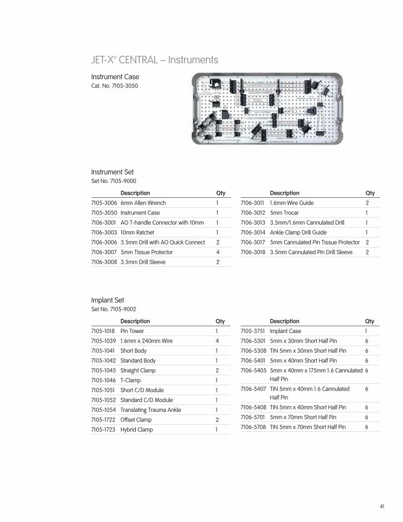
JET-X™ CENTRAL – InstrumentsInstrument Case Cat. No. 7105-3050
Instrument SetSet No. 7105-9000
Description Qty
7105-3006 6mm Allen Wrench 1
7105-3050 Instrument Case 1
7106-3001 AO T-handle Connector with 10mm 1
7106-3003 10mm Ratchet 1
7106-3006 3.5mm Drill with AO Quick Connect 2
7106-3007 5mm Tissue Protector 4
7106-3008 3.5mm Drill Sleeve 2
Description Qty
7106-3011 1.6mm Wire Guide 2
7106-3012 5mm Trocar 1
7106-3013 3.5mm/1.6mm Cannulated Drill 1
7106-3014 Ankle Clamp Drill Guide 1
7106-3017 5mm Cannulated Pin Tissue Protector 2
7106-3018 3.5mm Cannulated Pin Drill Sleeve 2
Implant SetSet No. 7105-9002
Description Qty
7105-1018 Pin Tower 1
7105-1039 1.6mm x 240mm Wire 4
7105-1041 Short Body 1
7105-1042 Standard Body 1
7105-1045 Straight Clamp 2
7105-1046 T-Clamp 1
7105-1051 Short C/D Module 1
7105-1052 Standard C/D Module 1
7105-1054 Translating Trauma Ankle 1
7105-1722 Offset Clamp 2
7105-1723 Hybrid Clamp 1
Description Qty
7105-3751 Implant Case 1
7106-5301 5mm x 30mm Short Half Pin 6
7106-5308 TiN 5mm x 30mm Short Half Pin 6
7106-5401 5mm x 40mm Short Half Pin 6
7106-5405 5mm x 40mm x 175mm 1.6 Cannulated Half Pin
6
7106-5407 TiN 5mm x 40mm 1.6 Cannulated Half Pin
6
7106-5408 TiN 5mm x 40mm Short Half Pin 6
7106-5701 5mm x 70mm Short Half Pin 6
7106-5708 TiN 5mm x 70mm Short Half Pin 6
42
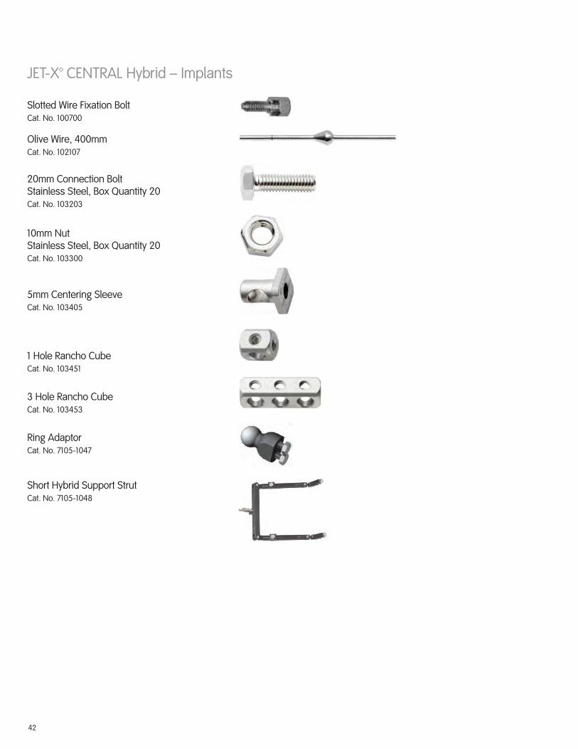
JET-X™ CENTRAL Hybrid – Implants
Slotted Wire Fixation Bolt Cat. No. 100700
Ring AdaptorCat. No. 7105-1047
Short Hybrid Support StrutCat. No. 7105-1048
Olive Wire, 400mm Cat. No. 102107
5mm Centering SleeveCat. No. 103405
1 Hole Rancho CubeCat. No. 103451
3 Hole Rancho CubeCat. No. 103453
20mm Connection BoltStainless Steel, Box Quantity 20Cat. No. 103203
10mm NutStainless Steel, Box Quantity 20 Cat. No. 103300

43
JET-X™ CENTRAL Hybrid – Implants
8mm Pin Clamp Spring Cat. No. 7105-3032
8mm Ball Joint Locking Bolt Cat. No. 7105-3038
8mm Body Bolt Cat. No. 7105-3030
Pin Clamp Locking Bolt, 8mm CapCat. No. 7105-3031
Long Hybrid Support StrutCat. No. 7105-1049
Dynamometric Wire TensionerCat. No. 7107-0341
8mm Central Body Lock Bolt Washer Cat. No. 7105-3033

44
Hybrid CaseCat. No. 7105-3060
JET-X™ CENTRAL Hybrid – Sets
Hybrid SetSet No. 7105-9004
Description Qty
100700 Wire Fixation Bolt, Slotted 5
102107 Wire with Stopper, 400mm 12
103203 Bolt, 20mm 20
103300 Nut, 10mm 20
103405 Centering Sleeve, 5mm 6
103451 Rancho Cube, 1 Hole 4
103453 Rancho Cube, 3 Hole 4
Description Qty
7105-1047 Ring Adaptor 1
7105-1048 Short Hybrid Strut 1
7105-1049 Long Hybrid Strut 1
7107-0341 Dynametric Wire Tensioner 1
7112-9401 Small Outer Case, 2.4 inches 1
7112-9402 Lid for Outer Case 1

45
Implant CaseCat. No. 7105-3751
JET-X™ CENTRAL Hybrid – Sets
Implant/Instrument SetSet No. 7105-9005
Description Qty
7105-1018 Pin Tower 1
7105-1039 1.6mm x 240mm Wire 4
7105-1041 Short Body 1
7105-1042 Standard Body 1
7105-1043 Long Body 1
7105-1045 Straight Clamp 2
7105-1046 T Clamp 1
7105-1051 C/D Module, Short 1
7105-1052 C/D Module, Standard 1
7105-1053 C/D Module, Long 1
7105-1054 Translating Trauma Ankle Clamp 1
7105-3006 6mm Allen Wrench 2
7105-3050 Instrument Case 1
7105-3751 Implant Case 1
7106-3001 AO T-handle Connector with 10mm Socket
1
7106-3003 10mm Ratchet 2
7106-3006 3.5mm Drill with AO Connector 2
7106-3007 5mm Tissue Protector 2
Description Qty
7106-3008 3.5mm Drill Sleeve 2
7106-3011 1.6mm Wire Guide 2
7106-3012 5mm Trocar 1
7106-3013 3.5mm/1.6mm Cannulated Drill 1
7106-3014 Ankle Clamp Drill Guide 1
7106-3017 5mm Cannulated Pin Tissue Protector 2
7106-3018 3.5mm Cannulated Pin Drill Sleeve 2
7106-5301 5mm x 30mm Short Half Pin 6
7106-5308 TiN 5mm x 30mm Short Half Pin 6
7106-5401 5mm x 40mm Short Half Pin 6
7106-5405 5mm x 40mm x 175mm 1.6mm Cannulated Half Pin
6
7106-5407 TiN 5mm x 40mm 1.6 Cannulated Half Pin
6
7106-5408 TiN 5mm x 40mm Short Half Pin 6
7106-5701 5mm x 70mm Short Half Pin 6
7106-5708 TiN 5mm x 70mm Short Half Pin 6
7106-7313 5mm Short Protector 2
7112-9400 Large Outer Case, 4.8 inches 1
7112-9402 Lid for Outer Case 1

46
Notes:

47
Notes:

™Trademark of Smith & Nephew. Reg. in US Pat. & TM Off. 7108-0633 REV0 10/11
Smith & Nephew, Inc.7135 Goodlett Farms ParkwayCordova, TN 38016USA
Telephone: 1-901-396-2121Information: 1-800-821-5700Orders/Inquiries: 1-800-238-7538
www.smith-nephew.com
©2011 Smith & Nephew, Inc.