Embed Size (px)
Citation preview
Experimental Facilities Division Progress Report1997-98
ANL/APS/TB-34
Table of Contents (All links are pdf files)
Acronyms
1 INTRODUCTION
1.1 Background1.2 Mission of the APS Experimental Facilities Division1.3 APS User Sector Layout1.4 XFD Organization1.5 User Operations1.6 APS User Administration and Technical Support1.7 R&D in Support of User Operations and Scientific Research1.8 SRI-CAT1.9 Collaborative Work1.10 Long-Term R&D Plans
2 XFD OPERATIONS
2.1 Introduction2.2 Installation and Commissioning Status2.3 Operations Experience2.4 Reliability Analysis2.5 Maintenance2.6 Beamline Operations
2.6.1 Introduction2.6.2 Insertion Devices2.6.3 Front Ends2.6.4 User Beamlines2.6.5 User Interfaces2.6.6 Sector 5 Front-End Problem
2.7 Interlock Systems and Instrumentation
2.7.1 The APS Personnel Safety System2.7.2 The Equipment Protection System2.7.3 Instrumentation2.7.4 Controls
2.8 Experiment Floor Operations
ANL/APS/TB-30 Table of Contents
http://www.aps.anl.gov/xfd/tech_bulletins/tb34/tb34.html (1 of 4) [05/01/2001 2:01:04 PM]
2.8.1 Shielding Validation of the Experiment Stations2.8.2 Measurement of Radiation Dose Received by IDs2.8.3 Measurement of Bremsstrahlung Absorbed Dose in Tissue Phantoms2.8.4 Photoneutron Dose Measurements in the First Optics Enclosures
3 USER ADMINISTRATIVE SUPPORT
3.1 APS Users
3.1.1 Collaborative Access Teams3.1.2 Independent Investigators/Collaborators3.1.3 User Community Description
3.2 User Support
3.2.1 User Communications3.2.2 User Registration, Orientation, and Badging3.2.3 User Data Management3.2.4 Support of User Advisory Groups3.2.5 Conference and Workshop Organization and Support3.2.6 User Agreements3.2.7 User Accounts3.2.8 User Policies and Procedures3.2.9 Beamline Design Reviews3.2.10 Technical Policy Support
3.3 User Safety
3.3.1 Experiment Safety Review3.3.2 Independent CAT Safety Assessments3.3.3 Safety Actions, Reviews, and Audits
4 USER TECHNICAL SUPPORT
4.1 X-ray Optics Fabrication and Metrology
4.1.1 X-ray Optics Metrology Laboratory4.1.2 Deposition Laboratory4.1.3 Fabrication Laboratory4.1.4 X-ray Characterization Laboratory4.1.5 X-ray Mirror Design and Characterization
4.2 Beamline Controls and Data Acquisition
4.2.1 Improvements in Scan Software4.2.2 Improvements in Data-Storage and Display Software4.2.3 Support for Message-Based Devices4.2.4 Support for Remote Beamline Operation4.2.5 Other Highlights
4.3 References
5 R&D IN SUPPORT OF OPERATIONS
ANL/APS/TB-30 Table of Contents
http://www.aps.anl.gov/xfd/tech_bulletins/tb34/tb34.html (2 of 4) [05/01/2001 2:01:04 PM]
5.1 Radiation Source Performance
5.1.1 Undulator A Performance5.1.2 Elliptical Multipole Wiggler Performance5.1.3 Circularly Polarized Undulator (CPU)5.1.4 Simultaneous Operation of Two Undulators5.1.5 5-mm Chamber and Undulator Measurements at 8.5-mm Gap5.1.6 Storage Ring Installation - Phase-25.1.7 Collaborations
5.2 Beamline Engineering
5.2.1 Introduction5.2.2 Brazing Capabilities for Beamline Components5.2.3 Beamline and Front-End Design for New Sectors and User Support5.2.4 Laser Doppler Angular Encoder with Sub-Nanoradian Sensitivity
5.3 X-ray Optics Development
5.3.1 Introduction5.3.2 Cryogenically Cooled Silicon Monochromators5.3.3 Diamond Monochromators5.3.4 High-Heat-Load Optics for the Future (or Enhanced Storage RingOperation)5.3.5 Other X-ray Optics Related Activities
5.4 New Instruments and Techniques
5.4.1 Introduction5.4.2 Sector 15.4.3 Sector 25.4.4 Sector 35.4.5 Sector 4
5.5 References
6 MAJOR PLANS FOR THE FUTURE
6.1 Summary of Major Plans for the Future6.2 Phase-2 Initiative
6.2.1 Background6.2.2 Beamline Plan in the APS Phase-2 Initiative
6.3 FEL Project
6.3.1 FEL Computer Code6.3.2 The FEL Line6.3.3 Characteristics of the FEL Undulator6.3.4 The Optical Diagnostics
6.4 Center for Combinatorial Materials Science and Technology6.5 Structural Genomics Project
ANL/APS/TB-30 Table of Contents
http://www.aps.anl.gov/xfd/tech_bulletins/tb34/tb34.html (3 of 4) [05/01/2001 2:01:04 PM]
6.6 References
7 APPENDICES
Appendix 1: 1997-1998 Publications by XFD Staff
Appendix 2: 1997-1998 Invited Presentations by XFD Staff
Appendix 3: SRI-CAT Staff and Members
Appendix 4: Review Status of APS Collaborative Access Teams
Appendix 5: User Agreement and Proprietary Account Status (8/25/98)
Appendix 6: XFD Safety Report for FY 1998
ANL/APS/TB-30 Table of Contents
http://www.aps.anl.gov/xfd/tech_bulletins/tb34/tb34.html (4 of 4) [05/01/2001 2:01:04 PM]
vii
Acronyms
AFM Atomic Force MicroscopeALS EPU Advanced Light Source Elliptically Polarized UndulatorANL Argonne National LaboratoryAPD Avalanche PhotodiodeAPS Advanced Photon SourceAPS RES Advanced Photon Source - Research InitiativeAPSUO Advanced Photon Source Users OrganizationASD Accelerator Systems Division
BCM Bent-Crystal MonochromatorBCTF Beamline Component Test FacilityBESSY Berliner Elektronenspeicherring-Gesellschaft fur SynchrotronstrahlungBM Bending MagnetBNL Brookhaven National LaboratoryBPM Beam Position Monitor
CAT Collaborative Access TeamCBT Computer-Based TrainingCCD Charge Coupled DeviceCCST Coordination Council for Science and TechnologyCHESS Cornell High Energy Synchrotron SourceCM Configuration ManagementCMS Chemical Management SystemCMB Center for Mechanistic Biology and Biotechnology at ANLCPU Circularly Polarized UndulatorCT Compact TensionCVD Chemical Vapor Deposition
DCM Double-Crystal MonochromatorDEC Digital Equipment CorporationDESY Deutsches Elektronen-SynchrotronDI Deionized WaterDMM Double-Multilayer MonochromatorDOE Department of EnergyDOT Department of TransportationDX Design ExchangeDXRL Deep X-ray Lithography
EMW Elliptical Multipole WigglerEPICS Experimental Physics and Industrial Control SystemEPS Equipment Protection SystemEQO ESH/QA Oversight GroupER Environmental ResearchESAF Experiment Safety Approval FormES&H Environmental, Safety and(or ESH) HealthESH-TR ESH Division’s Training SectionESRF European Synchrotron Radiation FacilityETS Equipment Tracking System
viii
FDR Final Design ReportFE Front EndFEA Finite Element AnalysisFEEPS Front-End Equipment Protection SystemFEL Free-Electron LaserFOE First Optics EnclosureFV Fast ValveFWHM Full Width Half Maximum
GERT General Employee Radiation Training
HazMats Hazardous MaterialsHDF Hierarchical Data Format
ID Insertion DeviceII Independent InvestigatorIIP Individual Investigator ProgramIOC Input/Output ControllerIR Infra-RedISI Interlock Systems and InstrumentationISM Integrated Safety Management
JHQ Job Hazard Questionnaire
LDAE Laser Doppler Angular EncoderLDDM Laser Doppler Displacement MeterLDRD Laboratory Directed Research & DevelopmentLN2 Liquid NitrogenLOM Laboratory/Office ModuleLTP Long Trace ProfilerLSO Laser Safety Officer
MCD Magnetic Circular DichroismMCS Magnetic Compton ScatteringMEMS Micro-Electromechanical SystemsMIT Massachusetts Institute of TechnologyMSD Materials Science Division at ANL
OUI Operator/User Interface
PDR Preliminary Design ReportPEB Program Evaluation BoardPHOENIX Phonon Excitation by Nuclear Inelastic Absorption of X-raysPLC Programmable Logic ControllerPMMA PolymethylmethacrylatePS1 Photon Shutter 1PS2 Photon Shutter 2PSD Power Spectral Density FunctionPSS Personnel Safety SystemPZT Piezoelectric Transducer
QA Quality Assurance
ix
RBC Red Blood CellsR&D Research & DevelopmentRE Rare EarthRF Radio FrequencyRGA Residual Gas Analyzerrms Root Mean Square
SASE Self-Amplified Spontaneous EmissionSGM Spherical Grating MonochromatorSI Strategic InitiativeSPring Super Photon Ring – 8 GeV (Japan)SRI Synchrotron Radiation InstrumentationSXM Scanning X-ray Microscope
TEY Total Electron YieldTLD Thermoluminescent DosimeterTMS Training Management SystemTTL Transitor-Transitor LogicTTU Topo Test Unit
UA2 Undulator A (sector 8)UHV Ultrahigh VacuumUTIG User Technical Interface Group
VDOS Vibrational Density of StatesVUV Vacuum Ultraviolet
XBPM X-ray Beam Position MonitorXFCS X-ray Fluorescence Correlation SpectroscopyXFD Experimental Facilities DivisionXFT X-ray Fluorescence TomographyXFM X-ray Fluorescence MicroscopyXIFS X-ray Intensity Fluctuation SpectroscopyXMD X-ray MicrodiffractionXMDC X-ray Magnetic Circular DichroismXMSAS X-ray Microbeam Small-Angle ScatteringXPS X-ray Polarization and Spectroscopy
1 INTRODUCTION
1
1.1 Background
This Progress Report summarizes theactivities of the APS Experimental FacilitiesDivision (XFD) over the period 1997-98.The XFD personnel focused on supportingthe Advanced Photon Source (APS) usersfrom day-to-day operations support to long-term research and development (R&D)needs. The XFD personnel would like toproudly share their major accomplishmentswith the readers of this report.
Over the past eighteen months, many newbeamlines have begun performing scientificresearch, and the user presence at the APShas grown continually. At Argonne NationalLaboratory (ANL), the APS has become thecenterpiece of user programs, and manyprogrammatic divisions at Argonne havestarted to derive the benefit of this majorresearch resource.
Thirty-five of the forty storage ring sectorsinclude both insertion device and bendingmagnet sources. Of these 35 sectors, theAccelerator Systems Division (ASD) usesradiation from one undulator (35-ID) andone bending magnet source (35-BM) toperform storage ring diagnostics. Theremaining 34 sectors are for the R&D workby the APS users.
In the first phase of the APS (Phase-1), 20 ofthese 34 sectors have been instrumentedbehind the shield wall to deliver insertiondevice and bending magnet radiation to theAPS users. As of August 1998, the usershave built beamlines in 19 of the 20 sectorsas planned, and XFD personnel haveinstalled and commissioned insertion
devices and beamline front ends to provideradiation to all the APS user beamlines. Inaddition, Personnel Safety Systems (PSS)have been designed to meet user needs.These PSS have been installed, validated,commissioned, and operated in over80 experiment stations on these beamlinesby XFD personnel in time to meet users’objectives. The majority of these beamlineshave taken advantage of the ‘standard andmodular’ beamline components designed,constructed, and tested by XFD.
The continued R&D support, advice, andguidance provided to the APS CollaborativeAccess Teams (CATs) by the XFDpersonnel has contributed to realizing earlyresearch at the majority of user beamlines.The Synchrotron Radiation Instrumentation(SRI) CAT, made up primarily of XFDpersonnel, has continued to make a majorimpact on the development of newinstruments and techniques, as well as onnew areas of science, using beamlines inthree sectors (1, 2, and 3). The ‘ScientificMembers’ of SRI-CAT have participatedextensively with the XFD staff inperforming frontier scientific research.
SRI-CAT has begun construction of abeamline in sector 4 that will be dedicated tothe development of instruments andtechniques to explore the frontiers of scienceusing polarized x-rays. In addition, XFD isnow getting ready for newer CATs planningto build beamlines in sectors beyond 21.
This report summarizes many of the primaryactivities and accomplishments of the XFDpersonnel in supporting APS users.
1 INTRODUCTION
2
1.2 Mission of the APSExperimental FacilitiesDivision
The mission of the XFD is unchanged and isconsistent with the vision of the APS tofunction as a reliable and preeminent sourceof synchrotron radiation for APS users.
XFD believes that we can best serve theAPS user community by investing in threeimportant goals: reliable and successfuloperation, high-quality user technical andadministrative support, and innovative R&Din support of user operations and scientificresearch. These goals enable us to gobeyond the traditional role of Department ofEnergy (DOE) user facilities to create anintelligent partnership with our users.
We commit ourselves to an organization thatshares the following principles:
• Understanding our users’ operationalgoals and striving to exceed theirneeds
• Providing seamless support to ourusers in all areas
• Creating a rewarding, enriching, andcollaborative R&D environment forour staff and the users to facilitatethe long-term success of the APS asthe premier user facility in the world
• Expanding our worldwide leadershiprole in the synchrotron radiationcommunity
• Assuring the safety of APS users,visitors, and APS/XFD personnel,and the protection of theenvironment
• Approaching our daily work withenthusiasm, a dedication to users anda sense of humor
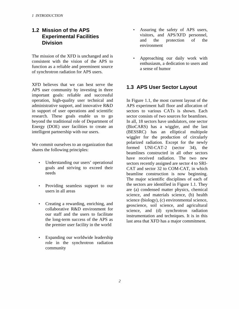
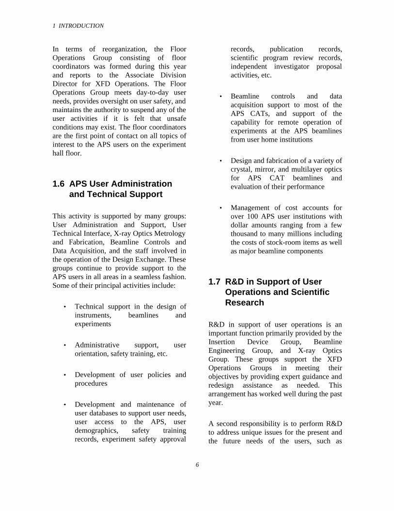
1.3 APS User Sector Layout
In Figure 1.1, the most current layout of theAPS experiment hall floor and allocation ofsectors to various CATs is shown. Eachsector consists of two sources for beamlines.In all, 18 sectors have undulators, one sector(BioCARS) has a wiggler, and the last(BESSRC) has an elliptical multipolewiggler for the production of circularlypolarized radiation. Except for the newlyformed UNI-CAT-2 (sector 34), thebeamlines constructed in all other sectorshave received radiation. The two newsectors recently assigned are sector 4 to SRI-CAT and sector 32 to COM-CAT, in whichbeamline construction is now beginning.The major scientific disciplines of each ofthe sectors are identified in Figure 1.1. Theyare (a) condensed matter physics, chemicalscience, and materials science, (b) healthscience (biology), (c) environmental science,geoscience, soil science, and agriculturalscience, and (d) synchrotron radiationinstrumentation and techniques. It is in thislast area that XFD has a major commitment.
1 INTRODUCTION
3
Fig. 1.1 APS Collaborative Access Teams by sector and discipline.
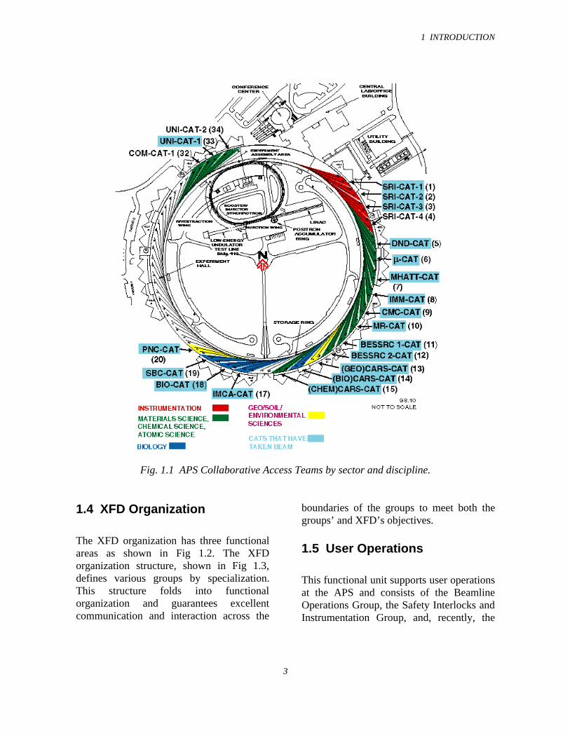
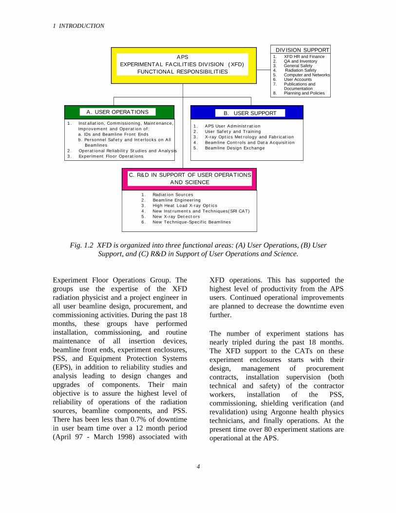
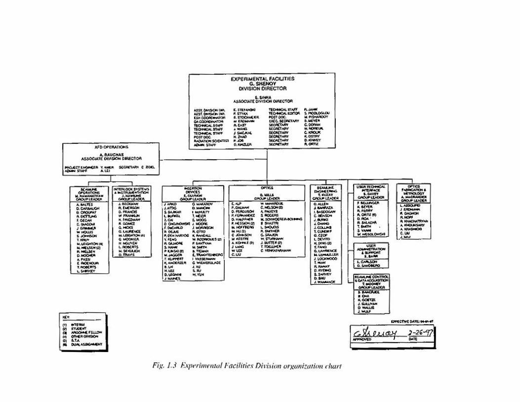
1.4 XFD Organization
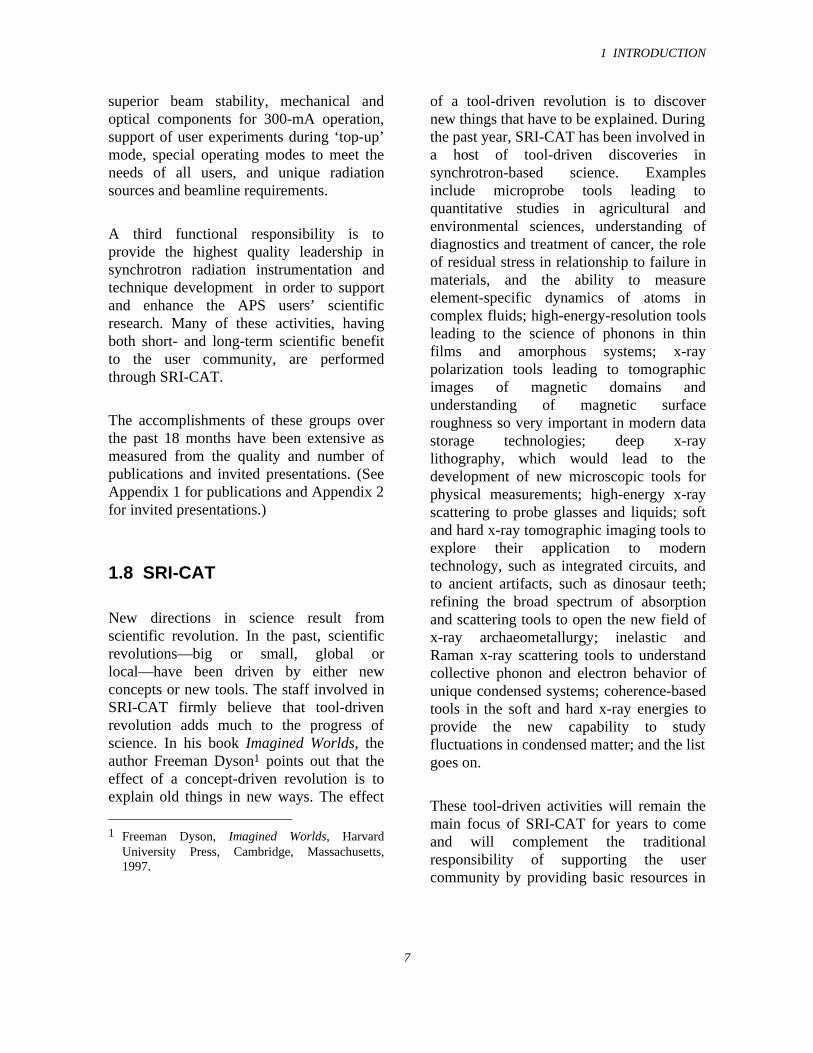
The XFD organization has three functionalareas as shown in Fig 1.2. The XFDorganization structure, shown in Fig 1.3,defines various groups by specialization.This structure folds into functionalorganization and guarantees excellentcommunication and interaction across the
boundaries of the groups to meet both thegroups’ and XFD’s objectives.
1.5 User Operations
This functional unit supports user operationsat the APS and consists of the BeamlineOperations Group, the Safety Interlocks andInstrumentation Group, and, recently, the
1 INTRODUCTION
4
C. R&D IN SUPPORT OF USER OPERATIONS AND SCIENCE
1. Radiation Sources2. Beamline Engineering3. High Heat Load X-ray Optics4. New Instruments and Techniques(SRI CAT)5. New X-ray Detectors6. New Technique-Specific Beamlines
DIVISION SUPPORT
1. APS User Administration2. User Safety and Training3. X-ray Optics Metrology and Fabrication4. Beamline Controls and Data Acquisition5. Beamline Design Exchange
B. USER SUPPORT
1. Installation, Commissioning, Maintenance, Improvement and Operation of:a. IDs and Beamline Front Endsb. Personnel Safety and Interlocks on All Beamlines
2. Operational Reliability Studies and Analysis3. Experiment Floor Operations
A. USER OPERATIONS
APSEXPERIMENTAL FACILITIES DIVISION (XFD)
FUNCTIONAL RESPONSIBILITIES
1. XFD HR and Finance2. QA and Inventory3. General Safety4. Radiation Safety5. Computer and Networks6. User Accounts7. Publications and Documentation8. Planning and Policies
Fig. 1.2 XFD is organized into three functional areas: (A) User Operations, (B) UserSupport, and (C) R&D in Support of User Operations and Science.
Experiment Floor Operations Group. Thegroups use the expertise of the XFDradiation physicist and a project engineer inall user beamline design, procurement, andcommissioning activities. During the past 18months, these groups have performedinstallation, commissioning, and routinemaintenance of all insertion devices,beamline front ends, experiment enclosures,PSS, and Equipment Protection Systems(EPS), in addition to reliability studies andanalysis leading to design changes andupgrades of components. Their mainobjective is to assure the highest level ofreliability of operations of the radiationsources, beamline components, and PSS.There has been less than 0.7% of downtimein user beam time over a 12 month period(April 97 - March 1998) associated with
XFD operations. This has supported thehighest level of productivity from the APSusers. Continued operational improvementsare planned to decrease the downtime evenfurther.
The number of experiment stations hasnearly tripled during the past 18 months.The XFD support to the CATs on theseexperiment enclosures starts with theirdesign, management of procurementcontracts, installation supervision (bothtechnical and safety) of the contractorworkers, installation of the PSS,commissioning, shielding verification (andrevalidation) using Argonne health physicstechnicians, and finally operations. At thepresent time over 80 experiment stations areoperational at the APS.
1 INTRODUCTION
6
In terms of reorganization, the FloorOperations Group consisting of floorcoordinators was formed during this yearand reports to the Associate DivisionDirector for XFD Operations. The FloorOperations Group meets day-to-day userneeds, provides oversight on user safety, andmaintains the authority to suspend any of theuser activities if it is felt that unsafeconditions may exist. The floor coordinatorsare the first point of contact on all topics ofinterest to the APS users on the experimenthall floor.
1.6 APS User Administrationand Technical Support
This activity is supported by many groups:User Administration and Support, UserTechnical Interface, X-ray Optics Metrologyand Fabrication, Beamline Controls andData Acquisition, and the staff involved inthe operation of the Design Exchange. Thesegroups continue to provide support to theAPS users in all areas in a seamless fashion.Some of their principal activities include:
• Technical support in the design ofinstruments, beamlines andexperiments
• Administrative support, userorientation, safety training, etc.
• Development of user policies andprocedures
• Development and maintenance ofuser databases to support user needs,user access to the APS, userdemographics, safety trainingrecords, experiment safety approval
records, publication records,scientific program review records,independent investigator proposalactivities, etc.
• Beamline controls and dataacquisition support to most of theAPS CATs, and support of thecapability for remote operation ofexperiments at the APS beamlinesfrom user home institutions
• Design and fabrication of a variety ofcrystal, mirror, and multilayer opticsfor APS CAT beamlines andevaluation of their performance
• Management of cost accounts forover 100 APS user institutions withdollar amounts ranging from a fewthousand to many millions includingthe costs of stock-room items as wellas major beamline components
1.7 R&D in Support of UserOperations and ScientificResearch
R&D in support of user operations is animportant function primarily provided by theInsertion Device Group, BeamlineEngineering Group, and X-ray OpticsGroup. These groups support the XFDOperations Groups in meeting theirobjectives by providing expert guidance andredesign assistance as needed. Thisarrangement has worked well during the pastyear.
A second responsibility is to perform R&Dto address unique issues for the present andthe future needs of the users, such as
1 INTRODUCTION
7
superior beam stability, mechanical andoptical components for 300-mA operation,support of user experiments during ‘top-up’mode, special operating modes to meet theneeds of all users, and unique radiationsources and beamline requirements.
A third functional responsibility is toprovide the highest quality leadership insynchrotron radiation instrumentation andtechnique development in order to supportand enhance the APS users’ scientificresearch. Many of these activities, havingboth short- and long-term scientific benefitto the user community, are performedthrough SRI-CAT.
The accomplishments of these groups overthe past 18 months have been extensive asmeasured from the quality and number ofpublications and invited presentations. (SeeAppendix 1 for publications and Appendix 2for invited presentations.)
1.8 SRI-CAT
New directions in science result fromscientific revolution. In the past, scientificrevolutions—big or small, global orlocal—have been driven by either newconcepts or new tools. The staff involved inSRI-CAT firmly believe that tool-drivenrevolution adds much to the progress ofscience. In his book Imagined Worlds, theauthor Freeman Dyson1 points out that theeffect of a concept-driven revolution is toexplain old things in new ways. The effect
1 Freeman Dyson, Imagined Worlds, Harvard
University Press, Cambridge, Massachusetts,1997.
of a tool-driven revolution is to discovernew things that have to be explained. Duringthe past year, SRI-CAT has been involved ina host of tool-driven discoveries insynchrotron-based science. Examplesinclude microprobe tools leading toquantitative studies in agricultural andenvironmental sciences, understanding ofdiagnostics and treatment of cancer, the roleof residual stress in relationship to failure inmaterials, and the ability to measureelement-specific dynamics of atoms incomplex fluids; high-energy-resolution toolsleading to the science of phonons in thinfilms and amorphous systems; x-raypolarization tools leading to tomographicimages of magnetic domains andunderstanding of magnetic surfaceroughness so very important in modern datastorage technologies; deep x-raylithography, which would lead to thedevelopment of new microscopic tools forphysical measurements; high-energy x-rayscattering to probe glasses and liquids; softand hard x-ray tomographic imaging tools toexplore their application to moderntechnology, such as integrated circuits, andto ancient artifacts, such as dinosaur teeth;refining the broad spectrum of absorptionand scattering tools to open the new field ofx-ray archaeometallurgy; inelastic andRaman x-ray scattering tools to understandcollective phonon and electron behavior ofunique condensed systems; coherence-basedtools in the soft and hard x-ray energies toprovide the new capability to studyfluctuations in condensed matter; and the listgoes on.
These tool-driven activities will remain themain focus of SRI-CAT for years to comeand will complement the traditionalresponsibility of supporting the usercommunity by providing basic resources in
1 INTRODUCTION
8
the development of new optics, beamlinecomponents, new techniques, etc.
The accomplishments and future plans ofSRI-CAT are discussed in more detailelsewhere in this document. (See Appendix3 for a list of current SRI-CAT members.)
1.9 Collaborative Work
During the past year the major collaborativeactivities of the XFD staff have been:
• Design and construction of allundulator vacuum chambers for thenew BESSY II storage ring in Berlin
• Design and construction of thevacuum chamber for the free-electron laser (FEL) project TESLAat HASYLAB
• Performance evaluation of theTESLA FEL undulator system
• Construction of critical high-heat-load components for the SPring-8undulator beamline front ends
• Design support to the beamlinegroup at the synchrotron radiationfacility in Taiwan
• Design and delivery of an 8-mm-aperture undulator vacuum chamberto the European SynchrotronRadiation Facility (ESRF)
• Beamline design support to COM-CAT, and assistance in managing
State of Illinois funds for thebeamlines
• Tuning of an undulator to meetunique technical specifications forthe operation of a 5-micron self-amplified spontaneous emission(SASE) FEL at Brookhaven NationalLaboratory (BNL)
This work is in addition to innumerablehours of technical support and adviceprovided to all APS users and the CATs.These efforts point to the high regard of theworld-wide synchrotron radiationcommunity for work performed by XFDstaff.
1.10 Long-Term R&D Plans
The staff in XFD actively participates inlong-term R&D activities. These activitiesare supported by Laboratory DirectedResearch and Development (LDRD) fundsdistributed by the Argonne NationalLaboratory Director through a laboratory-wide competitive process. These funds areprovided for the following four categories ofinitiatives:
1. Strategic Initiatives of theLaboratory (SI)
2. Research Initiatives of the APS(APS-RES)
3. Programs approved by theCoordination Council for Scienceand Technology to encourageinteractions between variousArgonne Divisions (CCST)

1 INTRODUCTION
9
4. Individual Investigator program topromote unique ideas fromindividuals (IIP)
The following is a list of LDRD programsfrom the XFD staff funded during FY 1998:
1. Development of a long undulatorline for a new generation ofsynchrotron radiation sources (SI)
2. Radiation damage to Nd-Fe-Bpermanent magnets due to very highradiation doses (SI)
3. Investigation of a SASE process in a5-micron FEL (SI)
4. Development of x-ray intensityfluctuation spectroscopy (XIFS) forstudy of atomic-scale equilibriumdynamics (SI with the MaterialsScience Division - MSD)
5. Anomalous inelastic x-ray scatteringwith meV resolution (SI)
6. Chemical vapor deposition (CVD)diamond imaging detector (SI)
7. Nanometer-resolution x-ray zoneplates (SI)
8. High-speed shutter for temporalmodification of the APS x-ray beam(SI)
9. Development of micromachiningtechnique based on deep x-raylithography (DXRL) (APS-RES)
10. Low work function coatings andLIGA-type fabrication (CCST withMSD)
11. Short-focal-length crystal lens foruse in medical imaging (IIP)
12. Compact laser Doppler linearencoder with near-angstromresolution (IIP)
2 XFD OPERATIONS
11
2.1 Introduction
The XFD Operations Organization isresponsible for assuring that the APSeffectively meets the operational needs ofthe user community and for assuring thatXFD and user activities conform to theapplicable requirements. In support of theAPS user activities, the XFD OperationsOrganization also gathers specific facilityoperating requirements, integrates therequests, determines the operating modesthat are needed to meet the requirements,and works with the Accelerator SystemsDivision (ASD) to satisfy the requirements.The Operations Organization is under thedirection of an Associate Division Directorfor Operations and includes three majorgroups: the Beamline Operations Group, theInterlock Systems and InstrumentationGroup, and the Experiment Floor OperationsGroup, as well as support staff to aid thegroup activities. The latter group wasorganized recently and consists of the floorcoordinators, who were transferred toOperations from the User TechnicalInterface Group. The activities of thesegroups are described in more detail in thefollowing sections.
2.2 Installation andCommissioning Status
The APS storage ring design incorporates amagnetic lattice with 35 5-meter-longstraight sections available for installation ofinsertion devices (IDs). The design alsoincorporates the necessary beam ports forextracting radiation from 35 of the 80storage ring bending magnets (BMs). Witheach sector containing an ID beamline and aBM beamline, the APS can accommodate atotal of 70 beamlines. The funding for the
APS Project included the funds to construct20 sectors worth of front ends (FEs) and IDsavailable for user research and an additionalsector for particle beam diagnostics studiesby the APS facility. All of these FEs and IDshave been installed, and most have beencommissioned and are providing beam to theuser beamlines. Two additional sectors havereceived funding, and work is underway tofabricate the necessary IDs and FEcomponents. Installation of thesecomponents is planned to begin in 1999. Theremaining 12 IDs and 24 FEs will be builtand installed as future funding becomesavailable.
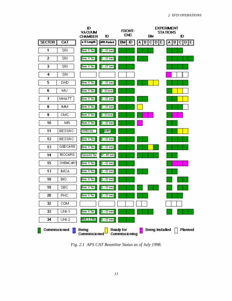
User beamline installation continues,although the installation schedule isprimarily governed by the user fundingavailability. The APS personnel areresponsible for managing the installationcontracts of the experiment stations andbeamline utilities. As of July 1998,101 experiment stations have beencompleted on 31 beamlines. Of these31 beamlines, all have had x-rays deliveredto at least the first optics enclosure (FOE).The dates for the start of commissioning, foreach of these beamlines, are shown inTable 2.1. Another seven stations are eitherunder construction or are planned for thenear future. The current beamline status isshown in Fig. 2.1.
2.3 Operations Experience
It is now three and one-half years since thestorage ring began commissioning onFebruary 20, 1995. The facility hasdeveloped and improved substantially overthat period. In calendar year 1996, about2000 hours of time were scheduled for useroperations. Last year, this number was
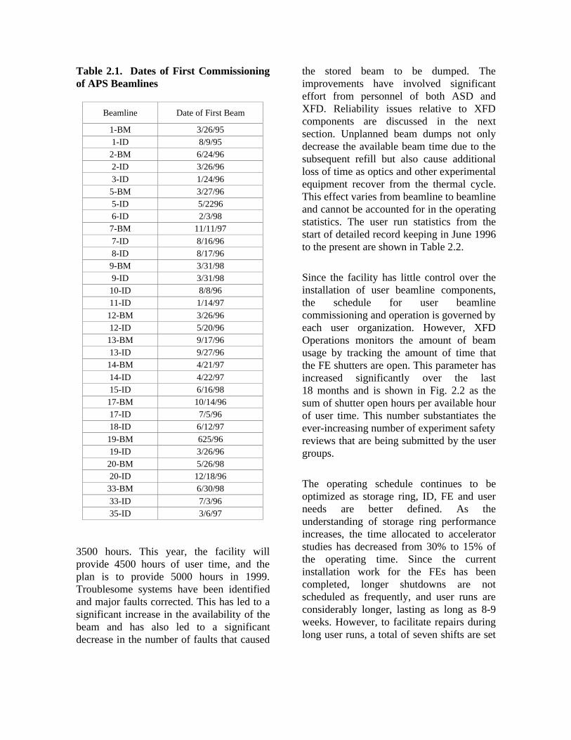
Table 2.1. Dates of First Commissioningof APS Beamlines
Beamline Date of First Beam
1-BM 3/26/951-ID 8/9/95
2-BM 6/24/962-ID 3/26/96
3-ID 1/24/965-BM 3/27/965-ID 5/22966-ID 2/3/98
7-BM 11/11/97
7-ID 8/16/968-ID 8/17/96
9-BM 3/31/989-ID 3/31/98
10-ID 8/8/9611-ID 1/14/97
12-BM 3/26/9612-ID 5/20/9613-BM 9/17/9613-ID 9/27/9614-BM 4/21/97
14-ID 4/22/9715-ID 6/16/9817-BM 10/14/9617-ID 7/5/9618-ID 6/12/97
19-BM 625/9619-ID 3/26/9620-BM 5/26/9820-ID 12/18/9633-BM 6/30/98
33-ID 7/3/9635-ID 3/6/97
3500 hours. This year, the facility willprovide 4500 hours of user time, and theplan is to provide 5000 hours in 1999.Troublesome systems have been identifiedand major faults corrected. This has led to asignificant increase in the availability of thebeam and has also led to a significantdecrease in the number of faults that caused
the stored beam to be dumped. Theimprovements have involved significanteffort from personnel of both ASD andXFD. Reliability issues relative to XFDcomponents are discussed in the nextsection. Unplanned beam dumps not onlydecrease the available beam time due to thesubsequent refill but also cause additionalloss of time as optics and other experimentalequipment recover from the thermal cycle.This effect varies from beamline to beamlineand cannot be accounted for in the operatingstatistics. The user run statistics from thestart of detailed record keeping in June 1996to the present are shown in Table 2.2.
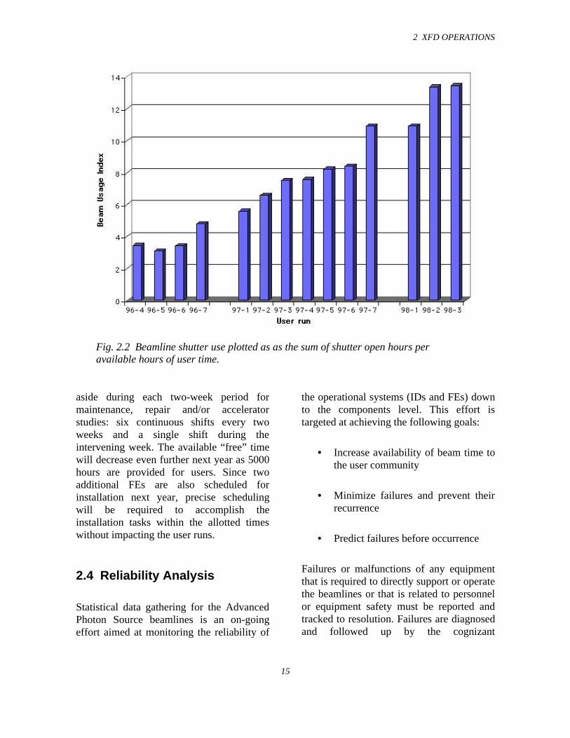
Since the facility has little control over theinstallation of user beamline components,the schedule for user beamlinecommissioning and operation is governed byeach user organization. However, XFDOperations monitors the amount of beamusage by tracking the amount of time thatthe FE shutters are open. This parameter hasincreased significantly over the last18 months and is shown in Fig. 2.2 as thesum of shutter open hours per available hourof user time. This number substantiates theever-increasing number of experiment safetyreviews that are being submitted by the usergroups.
The operating schedule continues to beoptimized as storage ring, ID, FE and userneeds are better defined. As theunderstanding of storage ring performanceincreases, the time allocated to acceleratorstudies has decreased from 30% to 15% ofthe operating time. Since the currentinstallation work for the FEs has beencompleted, longer shutdowns are notscheduled as frequently, and user runs areconsiderably longer, lasting as long as 8-9weeks. However, to facilitate repairs duringlong user runs, a total of seven shifts are set
2 XFD OPERATIONS
13
Fig. 2.1 APS CAT Beamline Status as of July 1998.
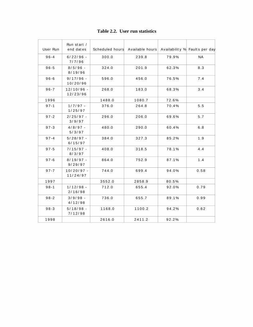
Table 2.2. User run statistics
User RunRun start /end dates Scheduled hours Available hours Availability % Faults per day
96-4 6/22/96 -7/7/96
300.0 239.8 79.9% NA
96-5 8/5/96 -8/19/96
324.0 201.9 62.3% 8.3
96-6 9/17/96 -10/20/96
596.0 456.0 76.5% 7.4
96-7 12/10/96 -12/23/96
268.0 183.0 68.3% 3.4
1996 1488.0 1080.7 72.6%
97-1 1/7/97 -1/25/97
376.0 264.8 70.4% 5.5
97-2 2/25/97 -3/9/97
296.0 206.0 69.6% 5.7
97-3 4/8/97 -5/3/97
480.0 290.0 60.4% 6.8
97-4 5/28/97 -6/15/97
384.0 327.3 85.2% 1.9
97-5 7/15/97 -8/3/97
408.0 318.5 78.1% 4.4
97-6 8/19/97 -9/29/97
864.0 752.9 87.1% 1.4
97-7 10/20/97 -11/24/97
744.0 699.4 94.0% 0.58
1997 3552.0 2858.9 80.5%
98-1 1/12/98 -2/16/98
712.0 655.4 92.0% 0.79
98-2 3/9/98 -4/12/98
736.0 655.7 89.1% 0.99
98-3 5/18/98 -7/12/98
1168.0 1100.2 94.2% 0.62
1998 2616.0 2411.2 92.2%
2 XFD OPERATIONS
15
Fig. 2.2 Beamline shutter use plotted as as the sum of shutter open hours peravailable hours of user time.
aside during each two-week period formaintenance, repair and/or acceleratorstudies: six continuous shifts every twoweeks and a single shift during theintervening week. The available “free” timewill decrease even further next year as 5000hours are provided for users. Since twoadditional FEs are also scheduled forinstallation next year, precise schedulingwill be required to accomplish theinstallation tasks within the allotted timeswithout impacting the user runs.
2.4 Reliability Analysis
Statistical data gathering for the AdvancedPhoton Source beamlines is an on-goingeffort aimed at monitoring the reliability of
the operational systems (IDs and FEs) downto the components level. This effort istargeted at achieving the following goals:
• Increase availability of beam time tothe user community
• Minimize failures and prevent theirrecurrence
• Predict failures before occurrence
Failures or malfunctions of any equipmentthat is required to directly support or operatethe beamlines or that is related to personnelor equipment safety must be reported andtracked to resolution. Failures are diagnosedand followed up by the cognizant
individuals and tracked/analyzed by thequality assurance (QA) reliability engineers.
All system/component performance datafrom the Experimental Physics andIndustrial Control System (EPICS) isconstantly logged and monitored. Thisfacilitates data gathering and analysis ofspecific trends and provides the flexibilityfor advance warning on failures. Problemscan then be dealt with in a pro-activemanner.
The life history of each critical component ismaintained in the Equipment TrackingSystem (ETS). This is a database systemwritten in ORACLE designed to archive keyinformation on beamline criticalcomponents.
The ETS can keep a complete history ofeach individual component from incominginspection to failure and/or removal fromservice. In addition, users can be notified ofmaintenance and calibration requirements ofcomponents when applicable. Hard copyreports are also available of all data to makeanalysis much easier and more useful.
This database has been adapted for use onthe APS Web page. The main benefit of thisexercise is to make the data more accessiblefor users. On the Web, a user/operator isable to obtain a complete FE or IDcomponent list on-screen simply by clickingon the appropriate sector prompt. The usercould then click on a specific component inthe list, and a pop-up window will appearwith more detailed information on thecomponent of interest.
Another benefit of adapting the ETS to theWeb is the ability to connect the ETSdatabase fields with current XFD Operations
Web sites. XFD Operations is currentlyemploying a failure reporting system calledTrouble Reports on the Web. TroubleReports are generated when any problemarises during normal operations. Datagathered from the trouble reports and therepair logs are analyzed for failurecorrelations and trends.
In order to pro-actively maintain thebeamline components, the ETS also has thecapability of generating maintenanceschedules for performing preventivemaintenance during beam shutdown periods.
To date, 43 FEs and 21 ID systems are in theoperational stage. Failure or malfunctiondata have been collected on these systemsby XFD personnel through the construction,installation, and operation phases of the APSFEs and IDs. The data have been organizedinto two main groups: 1) critical componentrejections during incoming inspection, and2) failures after component installation andoperation. Rejections during incominginspection are documented using the ANLnonconformance reports and are also enteredinto the XFD ETS database. Componentanomalies after installation and operationare logged into the XFD Operations TroubleReports, which are Web based.
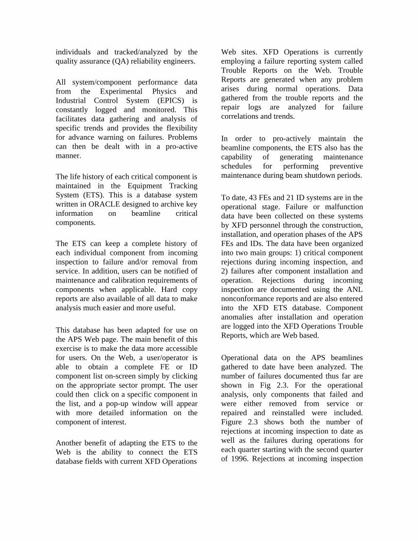
Operational data on the APS beamlinesgathered to date have been analyzed. Thenumber of failures documented thus far areshown in Fig 2.3. For the operationalanalysis, only components that failed andwere either removed from service orrepaired and reinstalled were included.Figure 2.3 shows both the number ofrejections at incoming inspection to date aswell as the failures during operations foreach quarter starting with the second quarterof 1996. Rejections at incoming inspection
2 XFD OPERATIONS
17
Fig. 2.3 Statistical data on component performance.
do not appear after Quarter II 1996, becausethe majority of critical components for theFEs and IDs were already inspected at thattime. A manufacturing problem with the FEpressure transmitters led to rejection of380 units accounting for 41% of the totalrejections.
Failures after installation and operation fallinto three main categories: mechanical,electrical, and vacuum. Electrical andmechanical failures are the most prevalent,occurring in cases such as modules for thePSS and EPS, encoders, controllers, andpressure transmitters. To a lesser extent,vacuum leaks have been recognized on FEequipment as well.
Analysis of the statistical data gathered forthe period covered by this report indicatesthe following:
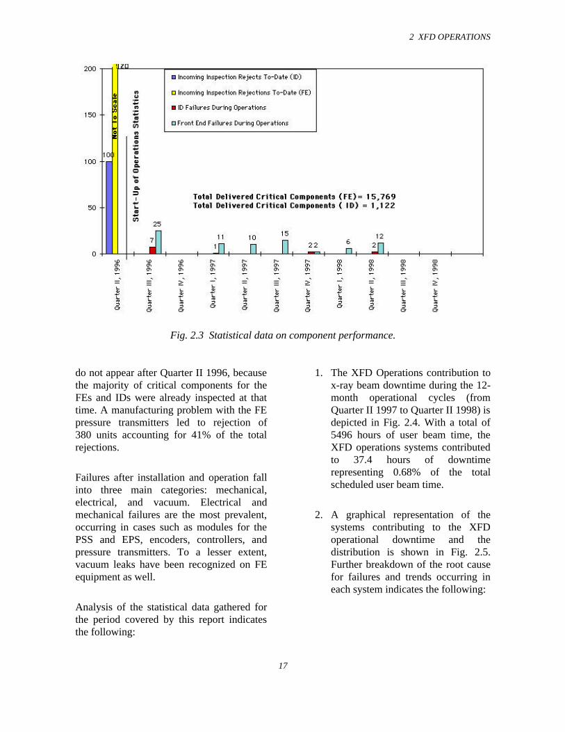
1. The XFD Operations contribution tox-ray beam downtime during the 12-month operational cycles (fromQuarter II 1997 to Quarter II 1998) isdepicted in Fig. 2.4. With a total of5496 hours of user beam time, theXFD operations systems contributedto 37.4 hours of downtimerepresenting 0.68% of the totalscheduled user beam time.
2. A graphical representation of thesystems contributing to the XFDoperational downtime and thedistribution is shown in Fig. 2.5.Further breakdown of the root causefor failures and trends occurring ineach system indicates the following:
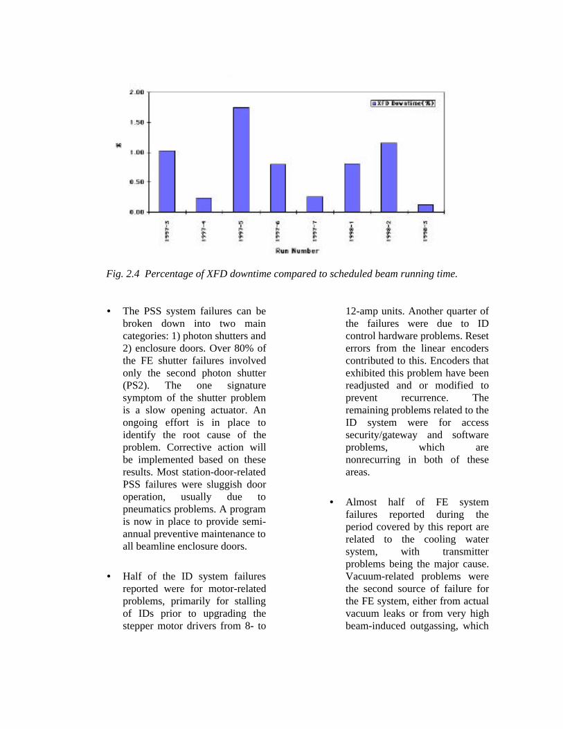
Fig. 2.4 Percentage of XFD downtime compared to scheduled beam running time.
• The PSS system failures can bebroken down into two maincategories: 1) photon shutters and2) enclosure doors. Over 80% ofthe FE shutter failures involvedonly the second photon shutter(PS2). The one signaturesymptom of the shutter problemis a slow opening actuator. Anongoing effort is in place toidentify the root cause of theproblem. Corrective action willbe implemented based on theseresults. Most station-door-relatedPSS failures were sluggish dooroperation, usually due topneumatics problems. A programis now in place to provide semi-annual preventive maintenance toall beamline enclosure doors.
• Half of the ID system failuresreported were for motor-relatedproblems, primarily for stallingof IDs prior to upgrading thestepper motor drivers from 8- to
12-amp units. Another quarter ofthe failures were due to IDcontrol hardware problems. Reseterrors from the linear encoderscontributed to this. Encoders thatexhibited this problem have beenreadjusted and or modified toprevent recurrence. Theremaining problems related to theID system were for accesssecurity/gateway and softwareproblems, which arenonrecurring in both of theseareas.
• Almost half of FE systemfailures reported during theperiod covered by this report arerelated to the cooling watersystem, with transmitterproblems being the major cause.Vacuum-related problems werethe second source of failure forthe FE system, either from actualvacuum leaks or from very highbeam-induced outgassing, which
2 XFD OPERATIONS
19
Fig. 2.5 System/component failures impacting beamline operations indelivering 5496 hours of user beam time.
caused high pressure levels thattripped setpoint-actuated inter-locks. The most significantfailure occurred in March 1998,when a ratchet-wall collimatordeveloped a major leak taking anentire beamline off-line (seesections 2.6.6 and 5.2.2).
• Failures reported for the EPSsystem are usually due toproblems, such as vacuum orwater systems, that cause an EPStrip. Since the APS becameoperational in December of 1996,the FE EPS system has neverfailed as an operational system.
2.5 Maintenance
The maintenance program of the XFDoperational systems consists of three parts:
1) Preventive maintenance includes tasksperformed on a scheduled periodic basisto prevent failures while equipment is inuse. This is accomplished in part byconstantly monitoring equipmentperformance via the EPICS data logs.Maintenance schedules of this nature aredriven mainly by beam run-timeschedules due to the fact that much ofthe work can only be performed duringshutdown periods. In addition, asshutdown time decreases, it becomes
critical to optimize the amount of workperformed. Undulator maintenance is aprime example of this.
2) Reliability-centered maintenanceincludes a scheduled maintenanceprogram that increases the availability ofan item of equipment by identifyingfailures or potential failures before theydegrade equipment effectiveness.Examples of this type of maintenanceare the semi-annual PSS validation anddoor maintenance program.
3) Emergency maintenance includesaccidental failures for which a goodinventory of spare parts is maintained.
2.6 Beamline Operations
2.6.1 Introduction
The Beamline Operations Group isresponsible for reliable operation of all FEsand IDs. In this effort, the Group regularlyuses the expertise of personnel in theInsertion Devices Group and the BeamlineEngineering Group in XFD. The BeamlineOperations Group is also responsible forproviding technical support to users. All thePhase-1 40 FEs and 20 IDs were installed.In addition, the ASD diagnostic beamline,sector 35, was commissioned with a specialundulator and a different type of FE. Duringthe past year, of the original 20 IDsinstalled, 19 provided radiation to thebeamlines on the experiment hall floor. Alsoof the 20 bending magnet beamlines, 12provided radiation to the beamlines on theexperiment hall floor. This past year was
mainly devoted to maintenance andupgrades of existing FEs and IDs.
2.6.2 Insertion Devices
Currently, a total of 22 IDs are installed in21 sectors of the storage ring. Most devicesare 3.3-cm-period undulators, 2.4 meterslong. Sector 2 has two devices installed, one3.3-cm-period undulator and one 5.5-cm-period undulator. Sector 3 has a 2.7-cm-period undulator. Sector 11 has an ellipticalmultipole wiggler (EMW). Sector 14 has an8.5-cm-period wiggler, and sector 35 has a1.8-cm-period 4.5-meter-long undulator.
The ID vacuum chamber in sector 3 wasreplaced with a small vertical aperturechamber with a maximum vertical openingof 5 mm and an external vertical size of 8mm. This change has enabled the 2.7-cm-period undulator to reach a gap of 8.5 mm,which corresponds to a first harmonicenergy of 5 keV, enhancing the capability ofthe sector 3 beamline.
All ID vacuum chambers have a transitionchamber at either end, which allows theconversion from the standard 40-mm-aperture storage ring chamber to the 8-mmID chamber. Internally, these transitionchambers are made of copper and are watercooled as they are exposed to a significantheat load during normal operation due toradio frequency (RF) heating. Recently onsome sectors there was a significant pressuredrop across these cooling lines. Thetechnique developed to clean FEcomponents was adapted to clean theseabsorber cooling lines. In addition thecooling circuits were reconfigured to be partof lower flow circuits.
2 XFD OPERATIONS
21
Upgrades to the IDs were undertaken toenhance their capabilities and to increasetheir reliability. All IDs, with the exceptionof the EMW in sector 11, were retrofittedwith new machine protection systemswitches and actuators. This arrangementallows the switches to trip at a gap of 50 mmand stay tripped at any gap larger than50 mm. The upgrade provides confirmationthat the gaps are effectively “open” withouthaving to fully open the devices to 200 mm.This capability has effectively reduced thestorage ring refill times by nearly 50%.During the past year, many of the devicesbegan stalling at moderate speeds. Toovercome this problem, the stepping motordrivers were upgraded from 8-amp to 12-amp capacity. More than half the sectors arecurrently equipped with the new steppingmotor drivers. The higher current driversallow the existing ID motors to producemore torque, resulting in more reliable IDoperation, faster acceleration, and higheropening and closing speeds. This is a majorbenefit to users who are “scanning” an ID,moving the gap to a new energy, and takingdata every few seconds. Linearpotentiometers were installed on all devicesas a redundant method of gap measurement.They can be used as input for the EPS. Theyare also used as inputs for a gap monitorsystem in sectors with multiple IDs, such assector 2, where two devices are installed andthe FE components cannot handle the powerof both devices simultaneously at fullyclosed gaps.
Extensive modifications were made to theID control software for more reliableoperation, user friendliness, and easierrevision when new features are added. Abeamline commissioning limit wasestablished, allowing users to specify aminimum gap for ID operation forprotection of their own beamline and
experimental components. This softwarelimit is independent of limits established forprotection of the ID, ID vacuum chamber,FE components, and experiment stations. A“deadband” was added to the controlprogram to allow users to specify a toleranceon the desired gap. This is especially usefulfor scanning of the ID in small steps over acertain energy range. Time is not wasted inextremely precise positioning of the ID iflower precision is acceptable for theexperimental demands of the user. The gap-to-energy conversion in the ID controlsoftware was enhanced. New code is used tocorrect the energy calculation to correspondmore closely to the x-ray energy. The finitebeam size is taken into consideration incalculating the energy for any specificharmonic and gap. Users were given theoption of specifying the required harmonic(maximum 7th order) for energy readbackand control values.
2.6.3 Front Ends
Currently there are 41 FEs installed, ofthese, 31 have provided radiation to theexperiment hall floor and 20 (includingsector 35-ID) are for ID beamlines. Duringthe course of the last few years of operation,certain inherent problems have surfaced. Inaddition to resolving these problems,upgrades and modifications have beenperformed.
The EPICS interface to the FE controls wasenhanced during the past year. Control ofthe all the devices is now possible viaEPICS. At the present time, floorcoordinators and operators can reset faultsand open and close vacuum valves remotelyfrom their workstations. Access security wasimplemented to avoid unwarranted operationof devices. In addition the FE system
manager can control all the vacuum pumps.Residual gas analyzers (RGAs) in all theFEs have been interfaced to EPICS,allowing for remote control and constantmonitoring of the RGAs, which is useful fordiagnosing vacuum problems. Alarmhandlers have been implemented in EPICSfor all FE systems. Advance warnings (inthe form of e-mail to pagers) warn ofpotential faults, so preventive action can betaken to rectify the problem.
In order to meet the CATs’ needs, seven ofthe ID FEs and one BM FE have beenretrofitted with differential pumps forwindowless operation of the beamlines.Windowless operation allows the beamlineto utilize lower energy x-rays and reducescattering. Also reduction of flux/brilliancedue to x-ray absorption in windowassemblies (containing a set of filters) isavoided. All these windowless beamlineshave an RGA just downstream of thedifferential pump. Work on interlocking andalarming on RGA signals is underway.
Problems have occurred in recent months onthe FE vacuum systems. The problems wereidentified to be one of two types. Thevacuum fast valve has sprung vacuum leaksin several FEs. The vacuum leak occurs atthe wire seal located in the ring surroundingthe conflat flange. Similar problems havebeen reported by other facilities when theybaked their valve to 250°C. (At the APS, itwas baked only to 150°C.) The seals havebeen replaced in some of the FEs, whichrequires venting half the FE and subsequentbaking. The other vacuum failure has beenattributed to the viton seal in the FE exitvalve located just outside the shield wall.This valve was chosen for its characteristicparticle-free nature, fast closing speed, and1-million-cycle lifetime. Failures wereobserved in the form of slow leaks through
the seal. Some of the valves were sent backto the manufacturer for analysis. Based onthese results, the manufacturer has modifiedthe valve and has rated the valve only for100,000 cycles and longer closing times.Thus, all future replacements will be madewith series 10 valves, which are 1/3 the cost.
One common failure mode during the pastyear has been due to the FE cooling watersystem. This failure triggers the protectionsystem to halt operation of both thebeamline and the storage ring. The problemhas been traced to the pressure-sensitivetransducers. The manufacturer hasacknowledged the problem in these devicesand has retrofitted them whenever thedevices were taken out of the system. Inaddition it was noticed that most of thecomponents in the FE were not meeting thedesign specification for coolant flow. Allmesh-based components in the FE weresubsequently cleaned by a techniquedeveloped locally. The cleaning cleared theblockages in the cooling channels andbrought flow rates to their design values.The output of the pressure transducers wasinterfaced to the EPS system. Each flow ordifferential pressure has both an upper- andlower-limit alarm that can trigger an inhibitfor operation of beamline/storage ring. Theupper-limit alarm was found unnecessaryand was removed. As an added preventivemeasure, EPICS alarms were set to notifystaff when the flow/pressure was within30% of the trip level. All theseenhancements have resulted in increasedreliability of this system.
Each FE has two x-ray beam positionmonitors (XBPMs) installed. These devicescan measure the position and angle in boththe vertical and horizontal planes in the caseof ID beamlines and in the vertical plane inBM beamlines. All the XBPMs in the FEswere instrumented. The current signals
2 XFD OPERATIONS
23
originating from the XBPMs were amplifiedand converted to voltage and fed to a fastADC processor. The digital output of theADC processor is transmitted via fiber opticto a VME-based receiver module. Thereceiver module is located in the storagering feedback input output controller (IOC)system. High-speed XBPM data areavailable for the storage ring feedbacksystem for future closed-orbit feedbacksystems. On 9 of 20 ID front ends, a digital-signal-processor-based XBPM calibratedsystem has been implemented. Oncecalibrated, this system reports the x-raybeam position in real units independent ofID gap or storage ring current.
2.6.4 User Beamlines
As the APS moves towards a matureoperational state, the Beamline OperationsGroup has started providing support to theusers on a regular basis. Most of thebeamlines use processed water for all theircomponent cooling needs. The processedwater for each sector is a closed-loop systemconsisting of a deionized (DI) water plantlocated in the mechanical mezzanine and adistribution system for each station. Most ofthe CATs have chosen the DI water plantdesigned by the APS. Beamline Operationshas taken on the responsibility ofcommissioning and subsequent maintenanceof the DI water systems for the CATs. TheCATs are provided round-the-clockcoverage for emergency repair service ontheir DI water plants.
The undulator beam delivered at the APShas very high power density and total power.Most of the beamlines use a monochromatoras their first optics to handle this powerfulbeam. Liquid nitrogen is the coolant ofchoice for the monochromator, as it keeps
the optics distortion at a minimum whileproviding the necessary cooling capacity tohandle the high head loads. Most of thebeamlines use an Oxford Instruments liquidnitrogen pump for pumping liquid nitrogenthrough the monochromator crystal. TheBeamline Operations Group has taken on theresponsibility for providing emergencyservice and routine maintenance of theseuser pumps. Spares needed for the service ofthese pumps are available to meetemergencies.
2.6.5 User Interfaces
At the Advanced Photon Source, all controlsare standardized with EPICS. This systemconsists of equipment interfaced to VME-based hardware. The VME crate (normallycalled the IOC) talks to the computers viathe Ethernet. With EPICS, access to thecontrols is available from any computerlocated on the same network. This schemehas a great degree of flexibility.
Most of the CATs have chosen EPICS as thecontrol system for their beamlines.Beamlines routinely need variousinformation from the APS control system. Amulti-prong approach was taken todisseminate the relevant information to theuser at the APS. The Web has been used asone platform for providing informationabout the machine. This information is notin real time. The Web platform is usedmostly for archived data and for informativepurposes. A cable TV system with 14-channel capability was installed around thestorage ring, and the information is alsodistributed to the rest of Argonne includingthe Guest House. At the current time, only 2of the 14 channels are being used. The dataare in real time providing information aboutthe storage ring operating status on one
channel and the beam pinhole image andsize on another channel. A plan is underwayto provide other desired information on therest of the channels in the future.
Users requiring data in real time cannot useeither of the above-mentioned schemesowing to the need for security and isolationof the control system. An EPICS interfacegateway has been developed to overcomethis limitation. A high-speed Unix-basedUltra Sparc system was set up with bridgesto the two networks. The gateway providesany data that are available in the controlsystem to the users as read-only on a real-time basis. In addition the gateway is used inspecific cases to provide specific usersaccess to control equipment in the controlsystem, for example, the IDs. For each ofthe ID beamlines, users can control their IDfrom designated computers.
The EPICS gateway has some limitations.Due to the large number of beamlines andusers, the performance of the gateway candegrade and will not be able to provide dataat the same rate as available on the controlsystem. Hence, for the present, the gatewayis throttled down to avoid any down time,while new solutions are sought to mitigatethis limitation.
A new system is being implemented using afiber optic link. Each beamline has adedicated multiconductor fiber optic cableinstalled from their respective ID controlsystem IOC (VME-based). The intent of thissystem is to provide a direct link from theAPS control system to the beamline controlsystem while making sure that security isnot compromised. The receiver module islocated in the beamline control systemIOCs. The data flow is unidirectional fromthe APS control system to the beamlines.
All CATs were provided with a stand-alonereceiver module. This module has displaysin the form of LEDs and an alpha-numericdisplay for current. In addition, it hasoutputs in the form of voltage, current loop,and frequency, corresponding to the storedbeam current. All LED displays have acorresponding transitor-transitor logic (TTL)signal for various bilevel signals likeinjection status, shutter status, orbitcorrection status, etc. In addition, therevolution clock signal (P0) is available onthese units for users performing timingexperiments.
A VME-based receiver module has beensuccessfully tested in one of the sectors. TheVME receiver module can be located at anyof the beamline station IOCs. The fiber opticlink is used by this receiver to provide thedata to the user’s experiment. The data fromthe APS control system are available to theusers seamlessly. Installation of the moduleis under way for the remaining sectors. TheVME-based receiver module has sector-specific information available to the usersdirectly in their IOCs. Some of these signalsare related to ID parameters, FE beamposition monitor (BPM) signals and storagering particle BPM signals for both the IDand BM beamlines, as well as FE shutterstatus. In addition, all the common signals,like storage ring current, injection status,etc., are also available.
The fiber optic information system helpsrelieve the load on the EPICS gateway. Inaddition, the users have the advantage ofhaving the data available directly in theirIOCs for seamless integration to theirexperimental setup. This system preservesthe high level of security to the APS controlsystem and also distributes the loaduniformly around the ring to various IOCs.Plans are under way to provide the users
2 XFD OPERATIONS
25
with bunch clock signals for timingexperiments.
2.6.6 Sector 5 Front-End Problem
At the APS, our first major failure of a FEtook place in March 1998, disabling thesector 5-ID beamline from operating for aperiod of about three weeks. During themaintenance period following the operatingcycle, the FE was fixed and the beamlinewas put on-line. The CAT lost about threeweeks of useful user beamline operationtime.
In early March, whenever the CAT closedthe device to small gaps there was anoticeable rise in the pressure in the FEvacuum system. As time passed, the vacuumfurther degraded, and the EPS disallowedthe opening of beamline shutters. During thenext available access to the storage ring,vacuum leak checking identified theproblem as the ratchet-wall collimator. Theratchet-wall collimator tube was found to bebent. At the next scheduled maintenancetime, the FE was surveyed, and allcomponents downstream of the slow valvewere removed. The second photon shutterand the safety shutter were found to be ingood condition. The ratchet-wall-collimatorvacuum chamber was bent, and a smallcrater was found about 3 inches from theupstream side of the collimator tube.
After extensive investigation and review, itwas determined that the wall collimator tubeshould not be constrained at both endsbecause the constraint prevented the wallcollimator tube from expanding andcontacting linearly. If both ends areconstrained, the tube can bend at the leastconstrained point. Once the tube started
bending, it was close to the beam and in aposistion to be exposed to heating from thebeam, which in turn resulted in furtherbending. Eventually the bottom surface ofthe collimator tube was in the path of thedirect undulator beam, which caused a craterand the subsequent vacuum failure.
At the current time, the cause of thecontraction of the collimator tube is notclear. However it was clear thatunconstraining the collimator tube wouldhave averted the failure. As a preventiveaction, all ratchet-wall collimators weremodified to allow for dimensional changesin the tube.
2.7 Interlock Systems andInstrumentation
The Interlock Systems and Instrumentation(ISI) Group is responsible for generatingand/or supporting the design, installation,testing, and maintenance of the PSS, EPS,and FE instrumentation. This includes anyand all documentation, testing, and field-work required for supplying the XFD withhigh reliability systems. Each systemconsists of numerous subsystems that arehigh reliability and fail safe. The PSS is aredundant interlocked system that monitorspersonnel access into beamline enclosures.The EPS is an interlocked system thatreduces risk of damage to FE beam transportequipment. The group is organized intothree functional blocks. The interlocksystem design section provides interlocksystems requirements, scheduling,budget/cost development and control,drafting, and project management support.These systems are designed to applicablecodes, orders, and standards for suchsystems. Software is developed in the
software development section under thesoftware development plan and conforms tothe Laboratory’s Software QualityAssurance Plan. The hardware function inthe hardware design section relates to thedesign, systems requirements, scheduling,budget/cost, drafting, and projectmanagement support of FE instrumentation.
2.7.1 The APS Personnel SafetySystem
Introduction
The APS is designed with the capability tooperate at least 70 beamlines concurrently.Each beamline includes several shieldedexperiment stations. Personnel access intothese stations is controlled during beamlineoperation via the APS/XFD PSS. The PSS isan engineered safety system that interlockspersonnel access to these stations with x-raybeam-off conditions via beam shutteroperation and, if required, storage ringoperation.
Although there are a variety of beamlinedesigns that reflect the types of experimentsbeing done at the APS, basic PSSconfiguration and control functions remainthe same. If required, specialized usercontrol panels are incorporated into thestandard library of PSS hardware.
The PSS is designed to comply withaccelerator safety standards in DOE Ordersand other relevant good practices foraccelerator facilities. Among therequirements derived from the abovecriteria, to which the PSS conforms, some ofthe more important items are as follows:
• The system is designed to be failsafe, so that common failure modesleave the PSS in a safe, beam-offstate.
• The designs incorporate redundantprotection, ensuring that no singlecomponent or subsystem failureleaves the PSS in an unsafecondition.
• Provisions for testing are included,so the proper component and systemfunction may be verified.
• Access and egress controls areincorporated so that personnel arenot exposed to x-ray radiation.These include emergency shut-offdevices, status signs, search andsecure procedures, and emergencyexit mechanisms.
• A strict configuration control systemprotects documentation, circuits andsoftware against unauthorized andinadvertent modification. Criticaldevices are clearly labeled to notethat tampering is strictly forbidden.
PSS Configuration Management Plan
Safety experts consider rigorousconfiguration management (CM) mandatoryfor any organization responsible fordeveloping safety critical systems. Thus,CM is essential to the mission of the ISIGroup. XFD has implemented CM thatprovides the mechanism whereby assurancescan be made that the appropriate system isbeing used.
2 XFD OPERATIONS
27
PSS Installation Status
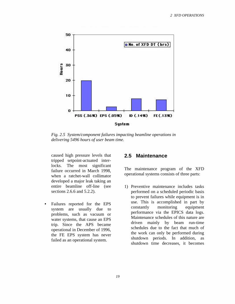
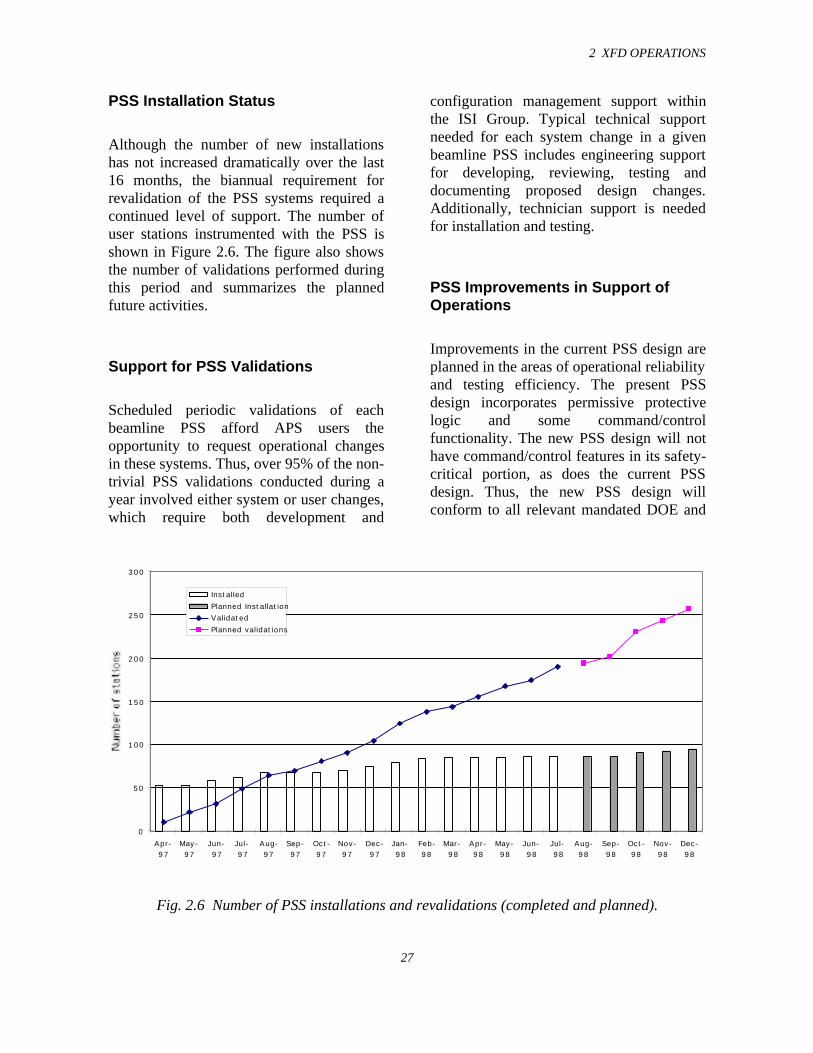
Although the number of new installationshas not increased dramatically over the last16 months, the biannual requirement forrevalidation of the PSS systems required acontinued level of support. The number ofuser stations instrumented with the PSS isshown in Figure 2.6. The figure also showsthe number of validations performed duringthis period and summarizes the plannedfuture activities.
Support for PSS Validations
Scheduled periodic validations of eachbeamline PSS afford APS users theopportunity to request operational changesin these systems. Thus, over 95% of the non-trivial PSS validations conducted during ayear involved either system or user changes,which require both development and
configuration management support withinthe ISI Group. Typical technical supportneeded for each system change in a givenbeamline PSS includes engineering supportfor developing, reviewing, testing anddocumenting proposed design changes.Additionally, technician support is neededfor installation and testing.
PSS Improvements in Support ofOperations
Improvements in the current PSS design areplanned in the areas of operational reliabilityand testing efficiency. The present PSSdesign incorporates permissive protectivelogic and some command/controlfunctionality. The new PSS design will nothave command/control features in its safety-critical portion, as does the current PSSdesign. Thus, the new PSS design willconform to all relevant mandated DOE and
Fig. 2.6 Number of PSS installations and revalidations (completed and planned).
0
50
100
150
200
250
300
Apr-97
May-97
Jun-97
Jul-97
Aug-97
Sep-97
Oct-97
Nov-97
Dec-97
Jan-98
Feb-98
Mar-98
Apr-98
May-98
Jun-98
Jul-98
Aug-98
Sep-98
Oct-98
Nov-98
Dec-98
Installed
Planned Installation
Validated
Planned validations
ANL safety design criteria and will providebetter operational performance, withvirtually exhaustive safety test coveragewhile reducing the testing duration.Ultimately this means a more seamless PSSinterface for the APS users while providingmore enhanced personnel access safety.
PSS EPICS Interface
Based on run time experience, it is evidentthat the PSS must have significantdiagnostics available to minimize userbeamline downtime.
Furthermore, quick accurate troubleanalysis, useful data logging of PSSparameters, and user “remote”operation/monitoring of some PSSparameters not only enhance beamlineoperating efficiencies but provide essentialinformation for preventative maintenance.These fundamental diagnostic and loggingtools are best provided via an EPICSinterface with the PSS.
The needed diagnostics and loggingcapabilities will be provided by configuringthe PSS EPICS so there is one PSS EPICSIOC per beamline.
2.7.2 The Equipment ProtectionSystem
Introduction
The APS has presented a number of designchallenges in protecting FE and beamlinecomponents from being damaged by thermalloads produced by high-brilliance hard
x-rays. Another major goal is to ensure thatthe storage ring vacuum is not compromisedunder any vacuum-failure scenario in the FEor beamline.
The FE Equipment Protection System(FEEPS) monitors and controls deviceslocated in the beamline FEs. Actions takendepend largely on the severity of the fault,ranging from merely setting an alarm, toclosing shutters and valves, to inhibitingstored beam. One of the majorconsiderations driving system design was tolimit beam aborts thus contributing to higheroperating efficiency of the facility.
Fail-safe principles are incorporated into thedesign, and the system will lapse into apredetermined safe condition (de-energizedto trip) following a failure, including loss ofpower, air-pressure drop, drop in water flow,shorted outputs, and open circuits.
System Overview
Programmable logic controllers (PLCs) areused to handle all system monitoring,control, troubleshooting, and reportingfunctions. PLCs allow for the design of avery advanced interlock and control systemthat can handle a large number of distributedI/O points. Each FE is provided with anautonomous equipment protection systemthat monitors the following parameters:cooling water flow and differential pressure,vacuum sensors, pneumatic pressure, photonand safety shutter positions, positions ofvacuum valves, and status of the systems towhich the FEEPS interfaces
In order to isolate different power systems,all interfaces between the FEEPS and othersystems and subsystems are implemented
2 XFD OPERATIONS
29
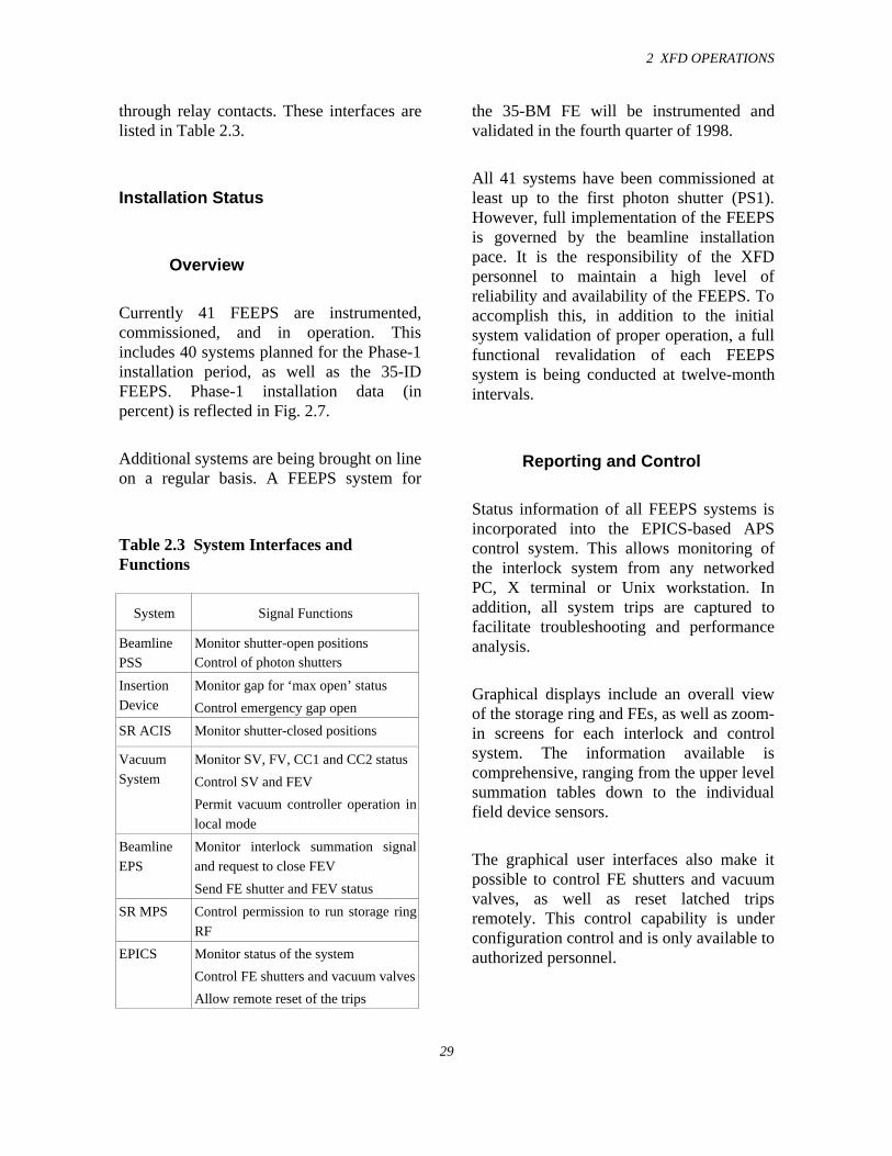
through relay contacts. These interfaces arelisted in Table 2.3.
Installation Status
Overview
Currently 41 FEEPS are instrumented,commissioned, and in operation. Thisincludes 40 systems planned for the Phase-1installation period, as well as the 35-IDFEEPS. Phase-1 installation data (inpercent) is reflected in Fig. 2.7.
Additional systems are being brought on lineon a regular basis. A FEEPS system for
Table 2.3 System Interfaces andFunctions
System Signal Functions
Beamline
PSS
Monitor shutter-open positionsControl of photon shutters
Insertion
Device
Monitor gap for ‘max open’ status
Control emergency gap open
SR ACIS Monitor shutter-closed positions
Vacuum
System
Monitor SV, FV, CC1 and CC2 status
Control SV and FEV
Permit vacuum controller operation in
local mode
Beamline
EPS
Monitor interlock summation signal
and request to close FEV
Send FE shutter and FEV status
SR MPS Control permission to run storage ring
RF
EPICS Monitor status of the system
Control FE shutters and vacuum valves
Allow remote reset of the trips
the 35-BM FE will be instrumented andvalidated in the fourth quarter of 1998.
All 41 systems have been commissioned atleast up to the first photon shutter (PS1).However, full implementation of the FEEPSis governed by the beamline installationpace. It is the responsibility of the XFDpersonnel to maintain a high level ofreliability and availability of the FEEPS. Toaccomplish this, in addition to the initialsystem validation of proper operation, a fullfunctional revalidation of each FEEPSsystem is being conducted at twelve-monthintervals.
Reporting and Control
Status information of all FEEPS systems isincorporated into the EPICS-based APScontrol system. This allows monitoring ofthe interlock system from any networkedPC, X terminal or Unix workstation. Inaddition, all system trips are captured tofacilitate troubleshooting and performanceanalysis.
Graphical displays include an overall viewof the storage ring and FEs, as well as zoom-in screens for each interlock and controlsystem. The information available iscomprehensive, ranging from the upper levelsummation tables down to the individualfield device sensors.
The graphical user interfaces also make itpossible to control FE shutters and vacuumvalves, as well as reset latched tripsremotely. This control capability is underconfiguration control and is only available toauthorized personnel.
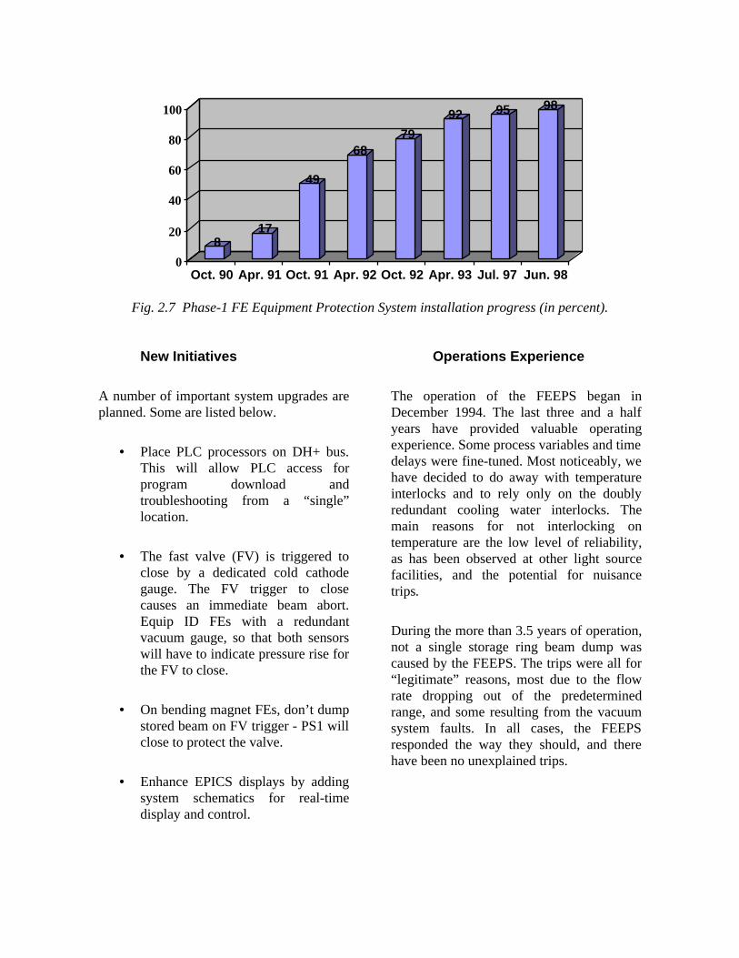
817
49
6879
92 95 98
0
20
40
60
80
100
Oct. 90 Apr. 91 Oct. 91 Apr. 92 Oct. 92 Apr. 93 Jul. 97 Jun. 98
Fig. 2.7 Phase-1 FE Equipment Protection System installation progress (in percent).
New Initiatives
A number of important system upgrades areplanned. Some are listed below.
• Place PLC processors on DH+ bus.This will allow PLC access forprogram download andtroubleshooting from a “single”location.
• The fast valve (FV) is triggered toclose by a dedicated cold cathodegauge. The FV trigger to closecauses an immediate beam abort.Equip ID FEs with a redundantvacuum gauge, so that both sensorswill have to indicate pressure rise forthe FV to close.
• On bending magnet FEs, don’t dumpstored beam on FV trigger - PS1 willclose to protect the valve.
• Enhance EPICS displays by addingsystem schematics for real-timedisplay and control.
Operations Experience
The operation of the FEEPS began inDecember 1994. The last three and a halfyears have provided valuable operatingexperience. Some process variables and timedelays were fine-tuned. Most noticeably, wehave decided to do away with temperatureinterlocks and to rely only on the doublyredundant cooling water interlocks. Themain reasons for not interlocking ontemperature are the low level of reliability,as has been observed at other light sourcefacilities, and the potential for nuisancetrips.
During the more than 3.5 years of operation,not a single storage ring beam dump wascaused by the FEEPS. The trips were all for“legitimate” reasons, most due to the flowrate dropping out of the predeterminedrange, and some resulting from the vacuumsystem faults. In all cases, the FEEPSresponded the way they should, and therehave been no unexplained trips.
2 XFD OPERATIONS
31
2.7.3 Instrumentation
Instrumentation Improvement inSupport of Operations
A wireless communication network forefficient operations support is planned. Theintent is to provide a portable computer witha wireless communication interface that canbe used to assist in diagnosing PSS orFEEPS problems. This unit will supplysystem information, automated trouble-shooting guidance and voicecommunications that can be carried to thesystem hardware in question on theexperiment hall floor.
Engineering support is being provided forthe following beamline instrumentationprojects:
• High voltage solenoid pulser – theAPS has need of a high-speed x-raybeam chopper to be used within aprogram devoted to time-resolvedmeasurements. The required high-speed chopper will operate within atime window of 2.35 µs. Also, thebeam chopper motor must have thespeed, precision and stabilitynecessary to phase lock the timewindow of the beam chopper to therevolution frequency of the storagering and the variability to allowmatching the beam chopper timewindow opening to the “bucket”pattern of the APS synchrotronradiation. An 80K rpm motor fromSpeedring and associated feedbackcontrol is planned to implement thisdesign goal.
• Engineering analysis of FE shutteroperation using high-speed dataacquisition systems interfaced to theFE EPICS control system.
2.7.4 Controls
Due to the flexibility provided by EPICS, alldata are available at all times to anyone withaccess to the computer network. At the APS,we have a separate subnet with restrictedaccess for all the control systems. All theIOCs are located on this subnet. Thisprovides an added security fromunwarranted access to the IOCs. With thelocation of a EPICS gateway, data from thecontrol system are provided to other subnets.
In a typical FE, currently EPICS can onlyread and is not allowed to control. Allcontrols for the FE have to be performed at alocation on top of the storage ring. Allvacuum pump and gauge controllers areinterfaced with EPICS. The interfaceenables the ion pump current and thevacuum to be read continuously. All waterflow and pressure systems are alsointerfaced to EPICS via the RS-485 interfaceavailable in the interface controllers. Alldata from EPICS are constantly logged. Thisprovides for later analysis of specific trends.The constant monitoring of data provides uswith flexibility for advance warning onfailures, thereby preemptive action can betaken to avoid them.
The XBPM raw voltage signals for thecurrent amplifier are interfaced to thecontrol system via an RS-485 interface. Thenormalization of the raw signals isperformed in the IOC. All signals, both rawand normalized, are available via EPICS.
Insertion device control is also implementedwith EPICS. The ID motor controllers arecommanded by EPICS, and the encoders areused to read the precise position of thedevice. Using the EPICS gateway, addedsecurity control to the IDs is provided tospecific users of a particular beamline.
The PSS and FEEPS operator/user interface(OUI) is provided for APS facility use. Theremote OUI for PSS and FEEPS has thecapability to interface with EPICS. Userscreens have been developed thatgraphically represent the PSS status, and theremote OUI does not control any PSSfunctionality.
2.8 Experiment Floor Operations
In March 1998, the APS floor coordinatorsbecame members of the Experiment FloorOperations Group. Their principalresponsibilities remain the same: theyprovide the day-to-day technical support forthe APS users. In addition to their supportrole, the floor coordinators provide theprimary APS oversight of beamline opera-tions. The coordinators’ offices aredistributed around the experiment hall, withtwo coordinators assigned to the four sectorsthat are associated with a specific LOM.Floor coordinators familiarize themselveswith the operation of the beamlines withintheir areas of responsibility and have theauthority to suspend operations if they feelthat unsafe conditions may exist. Wheneverthe facility is operating or wheneverbeamlines are undergoing significantmodification, a floor coordinator will be “onduty” representing the APS.
During the past year, five floor coordinatorshave been hired. The floor coordinator team
is being built with personnel who areexperienced in a variety of different aspectsof the construction and operations ofresearch facilities. In addition to the on-the-job training for new coordinators, a seminarseries was organized to introduce thecoordinators to some of the experimentalprograms at the APS as well as to develop adeeper understanding of the detailedoperation of the APS technical systems. Asthe number of users increases, so does thevariety of samples and experiments on thebeamlines. The floor coordinator duties willexpand to provide service in the areas ofbiological, radioactive, and chemical samplehandling.
2.8.1 Shielding Validation of theExperiment Stations
The Experimental Facilities Division, incollaboration with the Health PhysicsPersonnel from ANL’s Environment, Safetyand Health (ES&H) Division, performs theshielding verification of all the userexperiment stations in the presence of CATpersonnel. The governing process forcommissioning is documented and has beenapproved by the DOE. The CATs areinformed immediately of any shieldingdeficiencies discovered during the enclosurecommissioning. Activity on the beamlinecannot proceed until the deficiency ismitigated. The CATs are allowed to proceedwith commissioning activity of beamlineinstruments only after successful completionof shielding verification of the enclosures.
Shielding verification is done forbremsstrahlung, synchrotron radiation, andneutrons. So far, 45 first optics enclosures/white-beam stations and 33 pink/mono-beam stations have been verified at the APS.
2 XFD OPERATIONS
33
2.8.2 Measurement of RadiationDose Received by IDs
The radiation dose received by the magneticstructures of the IDs was monitored for eachrun. Radiochromic films were placed atvarious locations by each of the IDs beforeeach run. The accumulated dose shows thatthe maximum dose received by the IDs untilnow is in the range of a few Mrads (5-10Mrads).
A program to study the degradation of thepermanent magnets as a result of highradiation doses is in progress. Nd-Fe-Bpermanent magnet samples will be irradiatedwith x-rays, gamma rays, and neutronsunder controlled conditions. The totalabsorbed dose in each case will be measuredby an appropriate high-dose dosimetrytechnique, such as radiochromic films orphotoluminescence dosimeters. Thetemperature of the magnet during irradiationwill be closely monitored. The first batch ofmagnets will be irradiated by x-rays at the20-BM beamline during Run 4 of 1998.Gamma irradiation will be measured at thehigh-dose Co-60 gamma cell (9 KGy/h) atNIST.
2.8.3 Measurement ofBremsstrahlung AbsorbedDose in Tissue Phantom
High-energy electron storage rings generateenergetic bremsstrahlung photons throughradiative interaction of electrons (orpositrons) with the residual gas moleculesand other components inside the storagering. At the APS, where the beamlines arechanneled out of the storage ring, acontinuous bremsstrahlung spectrum, with amaximum energy of the positron beam is
present. Measurement of the primarybremsstrahlung energy spectra has beenconducted at the APS ID beamlines and hasbeen reported in the Experimental FacilitiesDivision Progress Report 1996-97(ANL/APS/TB-30).
A polymethyl methacccrylate (PMMA) slabphantom of 30 cm × 30 cm × 30 cm is usedto measure the absorbed dose bybremsstrahlung radiation in tissue equivalentmaterial. Thermoluminescent dosimeters(TLDs) (LiF, TLD-700) are used to measurethe dose. The PMMA slabs were placed inthe bremsstrahlung beam in the FOE of the15-ID beamline. The TLDs measured theabsorbed dose in the longitudinal and thetransverse directions in the phantom. Thepreliminary results indicate a maximumnormalized absorbed dose rate of 1.0 × 10⁻²
mGy/h/nT/mA. Detailed analysis of thisexperiment is underway.
2.8.4 Photoneutron DoseMeasurements in the FirstOptics Enclosures
Bremsstrahlung of sufficiently high energy(>10 MeV) can interact with beamlinecomponents, such as beam stops andcollimators, generating neutrons of varyingenergies. There are three main processes bywhich neutrons may be produced by thehigh-energy bremsstrahlung photons: giantresonance dipole decay (10 < Eγ < 30 MeV),quasi-deuteron production and decay(50 <Eγ < 300 MeV), and a photopionproduced cascade (Eγ > 140 MeV). At theAPS, where bremsstrahlung energy can beas high as 7 GeV, production of neutronsinvarying yields is possible from all threeprocesses.

A simultaneous measurement ofbremsstrahlung and the correspondingphotoneutron dose rates from differenttargets like Fe, Cu, W, and Pb wasconducted at the FOE of the APS beamlinesto obtain the photoneutron dose rates as afunction of bremsstrahlung power. An
Andersson-Braun remmeter that houses asensitive 3He detector is used for neutrondose measurements. The dose equivalentrates, normalized to bremsstrahlung power,are measured with the four targets. Theresults are given in Fig. 2.8.
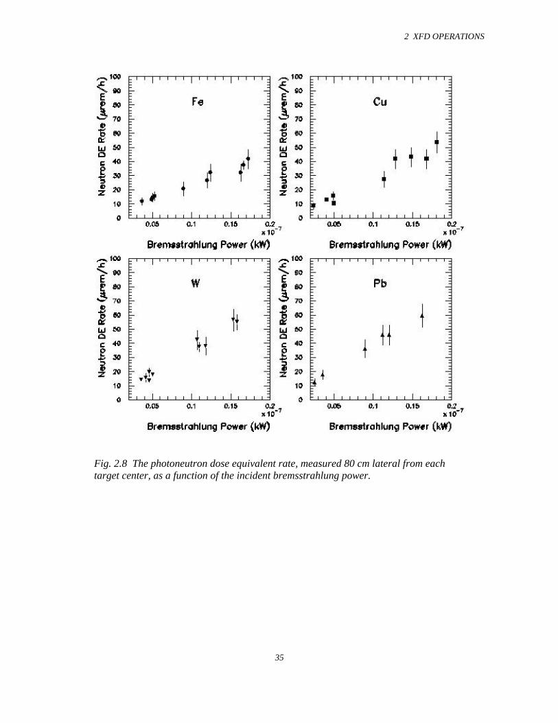
2 XFD OPERATIONS
35
Fig. 2.8 The photoneutron dose equivalent rate, measured 80 cm lateral from eachtarget center, as a function of the incident bremsstrahlung power.
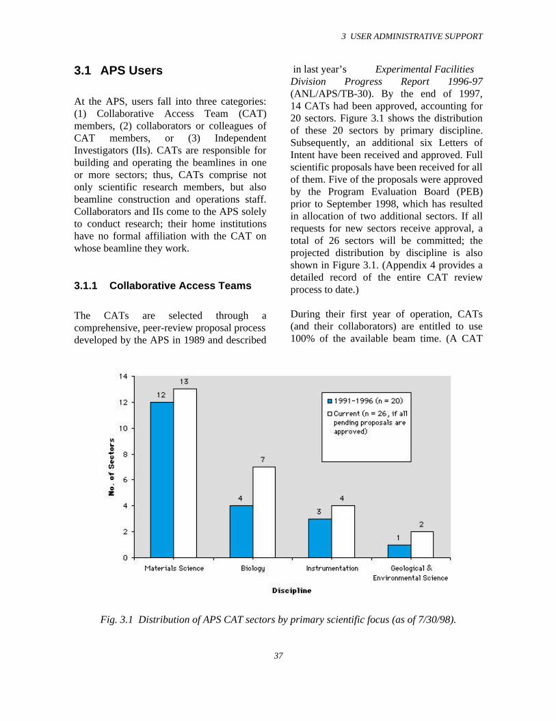
3 USER ADMINISTRATIVE SUPPORT
37
3.1 APS Users
At the APS, users fall into three categories:(1) Collaborative Access Team (CAT)members, (2) collaborators or colleagues ofCAT members, or (3) IndependentInvestigators (IIs). CATs are responsible forbuilding and operating the beamlines in oneor more sectors; thus, CATs comprise notonly scientific research members, but alsobeamline construction and operations staff.Collaborators and IIs come to the APS solelyto conduct research; their home institutionshave no formal affiliation with the CAT onwhose beamline they work.
3.1.1 Collaborative Access Teams
The CATs are selected through acomprehensive, peer-review proposal processdeveloped by the APS in 1989 and described
in last year’s Experimental FacilitiesDivision Progress Report 1996-97(ANL/APS/TB-30). By the end of 1997,14 CATs had been approved, accounting for20 sectors. Figure 3.1 shows the distributionof these 20 sectors by primary discipline.Subsequently, an additional six Letters ofIntent have been received and approved. Fullscientific proposals have been received for allof them. Five of the proposals were approvedby the Program Evaluation Board (PEB)prior to September 1998, which has resultedin allocation of two additional sectors. If allrequests for new sectors receive approval, atotal of 26 sectors will be committed; theprojected distribution by discipline is alsoshown in Figure 3.1. (Appendix 4 provides adetailed record of the entire CAT reviewprocess to date.)
During their first year of operation, CATs(and their collaborators) are entitled to use100% of the available beam time. (A CAT
Fig. 3.1 Distribution of APS CAT sectors by primary scientific focus (as of 7/30/98).
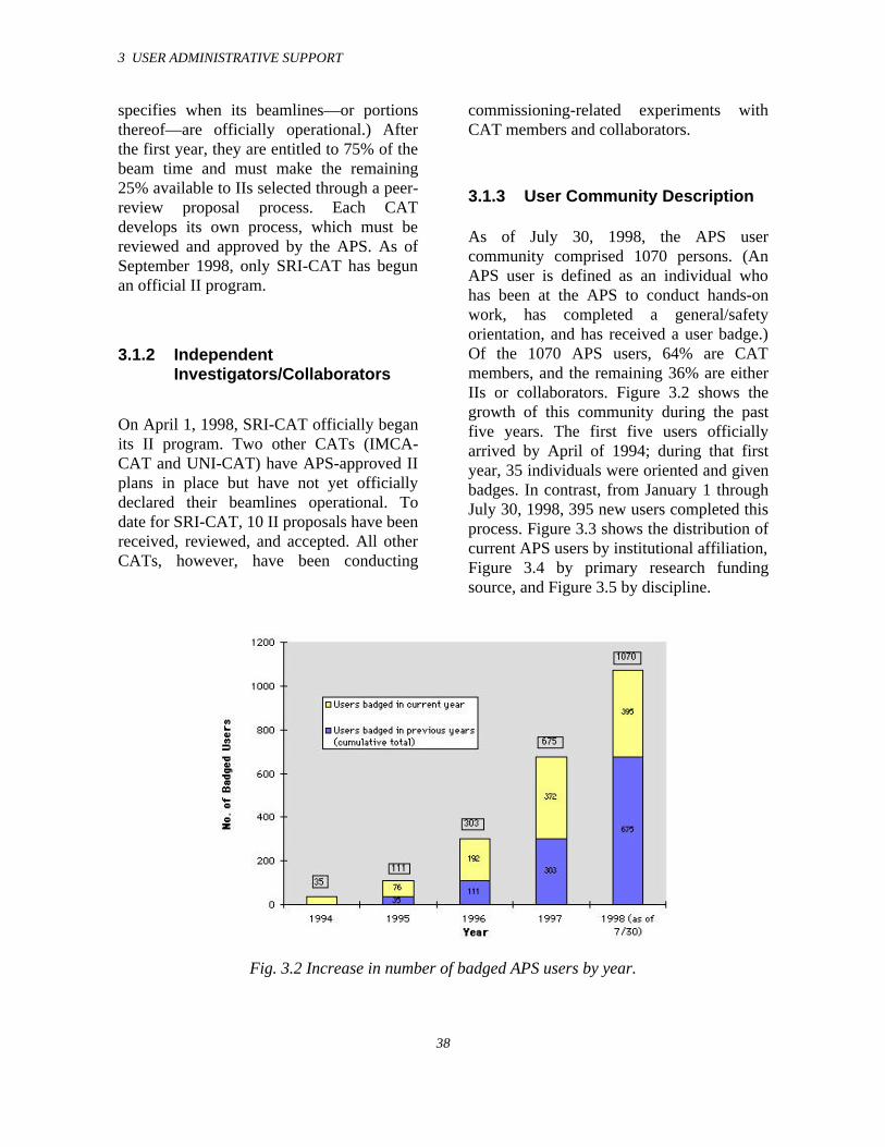
3 USER ADMINISTRATIVE SUPPORT
38
specifies when its beamlines—or portionsthereof—are officially operational.) Afterthe first year, they are entitled to 75% of thebeam time and must make the remaining25% available to IIs selected through a peer-review proposal process. Each CATdevelops its own process, which must bereviewed and approved by the APS. As ofSeptember 1998, only SRI-CAT has begunan official II program.
3.1.2 IndependentInvestigators/Collaborators
On April 1, 1998, SRI-CAT officially beganits II program. Two other CATs (IMCA-CAT and UNI-CAT) have APS-approved IIplans in place but have not yet officiallydeclared their beamlines operational. Todate for SRI-CAT, 10 II proposals have beenreceived, reviewed, and accepted. All otherCATs, however, have been conducting
commissioning-related experiments withCAT members and collaborators.
3.1.3 User Community Description
As of July 30, 1998, the APS usercommunity comprised 1070 persons. (AnAPS user is defined as an individual whohas been at the APS to conduct hands-onwork, has completed a general/safetyorientation, and has received a user badge.)Of the 1070 APS users, 64% are CATmembers, and the remaining 36% are eitherIIs or collaborators. Figure 3.2 shows thegrowth of this community during the pastfive years. The first five users officiallyarrived by April of 1994; during that firstyear, 35 individuals were oriented and givenbadges. In contrast, from January 1 throughJuly 30, 1998, 395 new users completed thisprocess. Figure 3.3 shows the distribution ofcurrent APS users by institutional affiliation,Figure 3.4 by primary research fundingsource, and Figure 3.5 by discipline.
Fig. 3.2 Increase in number of badged APS users by year.
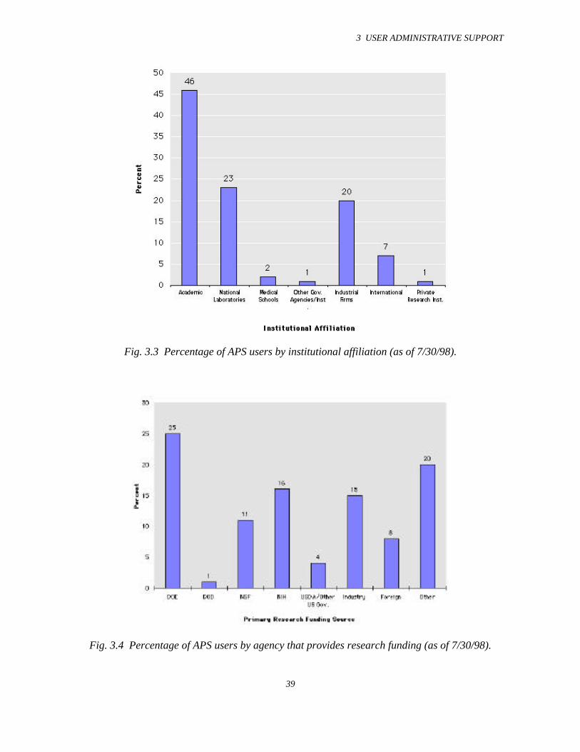
3 USER ADMINISTRATIVE SUPPORT
39
Fig. 3.3 Percentage of APS users by institutional affiliation (as of 7/30/98).
Fig. 3.4 Percentage of APS users by agency that provides research funding (as of 7/30/98).
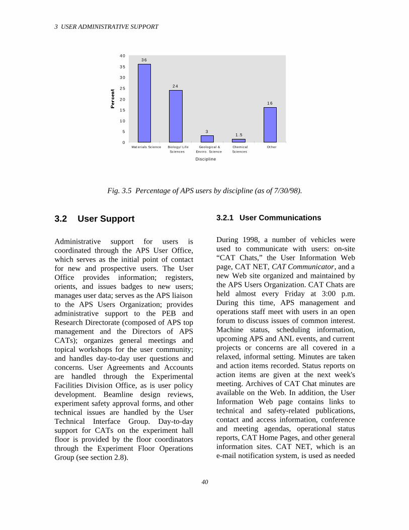
3 USER ADMINISTRATIVE SUPPORT
40
Fig. 3.5 Percentage of APS users by discipline (as of 7/30/98).
3.2 User Support
Administrative support for users iscoordinated through the APS User Office,which serves as the initial point of contactfor new and prospective users. The UserOffice provides information; registers,orients, and issues badges to new users;manages user data; serves as the APS liaisonto the APS Users Organization; providesadministrative support to the PEB andResearch Directorate (composed of APS topmanagement and the Directors of APSCATs); organizes general meetings andtopical workshops for the user community;and handles day-to-day user questions andconcerns. User Agreements and Accountsare handled through the ExperimentalFacilities Division Office, as is user policydevelopment. Beamline design reviews,experiment safety approval forms, and othertechnical issues are handled by the UserTechnical Interface Group. Day-to-daysupport for CATs on the experiment hallfloor is provided by the floor coordinatorsthrough the Experiment Floor OperationsGroup (see section 2.8).
3.2.1 User Communications
During 1998, a number of vehicles wereused to communicate with users: on-site“CAT Chats,” the User Information Webpage, CAT NET, CAT Communicator, and anew Web site organized and maintained bythe APS Users Organization. CAT Chats areheld almost every Friday at 3:00 p.m.During this time, APS management andoperations staff meet with users in an openforum to discuss issues of common interest.Machine status, scheduling information,upcoming APS and ANL events, and currentprojects or concerns are all covered in arelaxed, informal setting. Minutes are takenand action items recorded. Status reports onaction items are given at the next week'smeeting. Archives of CAT Chat minutes areavailable on the Web. In addition, the UserInformation Web page contains links totechnical and safety-related publications,contact and access information, conferenceand meeting agendas, operational statusreports, CAT Home Pages, and other generalinformation sites. CAT NET, which is ane-mail notification system, is used as needed
36
24
31.5
16
0
5
10
15
20
25
30
35
40
Materials Science Biology/LifeSciences
Geological &Enviro. Science
ChemicalSciences
Other
Discipline
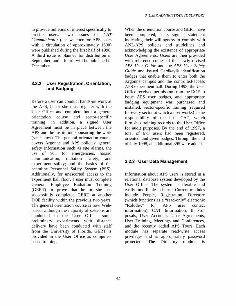
3 USER ADMINISTRATIVE SUPPORT
41
to provide bulletins of interest specifically toon-site users. Two issues of CATCommunicator (a newsletter for APS userswith a circulation of approximately 1600)were published during the first half of 1998.A third issue is planned for distribution inSeptember, and a fourth will be published inDecember.
3.2.2 User Registration, Orientation,and Badging
Before a user can conduct hands-on work atthe APS, he or she must register with theUser Office and complete both a generalorientation course and sector-specifictraining; in addition, a signed UserAgreement must be in place between theAPS and the institution sponsoring the work(see below). The general orientation coursecovers Argonne and APS policies; generalsafety information such as site alarms, theuse of 911 for emergencies, hazardcommunication, radiation safety, andexperiment safety; and the basics of thebeamline Personnel Safety System (PSS).Additionally, for unescorted access to theexperiment hall floor, a user must completeGeneral Employee Radiation Training(GERT) or prove that he or she hassuccessfully completed GERT at anotherDOE facility within the previous two years.The general orientation course is now Web-based; although the majority of sessions areconducted in the User Office, somepreliminary experiments with distancedelivery have been conducted with stafffrom the University of Florida. GERT isprovided in the User Office as computer-based training.
When the orientation course and GERT havebeen completed, users sign a statementindicating their willingness to comply withANL/APS policies and guidelines andacknowledging the existence of appropriateUser Agreements. Users are then providedwith reference copies of the newly revisedAPS User Guide and the APS User SafetyGuide and issued Cardkey® identificationbadges that enable them to enter both theArgonne campus and the controlled-accessAPS experiment hall. During 1998, the UserOffice received permission from the DOE toissue APS user badges, and appropriatebadging equipment was purchased andinstalled. Sector-specific training (requiredfor every sector at which a user works) is theresponsibility of the host CAT, whichfurnishes training records to the User Officefor audit purposes. By the end of 1997, atotal of 675 users had been registered,oriented, and given badges. Through the endof July 1998, an additional 395 were added.
3.2.3 User Data Management
Information about APS users is stored in arelational database system developed by theUser Office. The system is flexible andeasily modifiable in-house. Current modulesinclude People, Registration, Directory(which functions as a “read-only” electronic“Rolodex” for APS user contactinformation), CAT Information, II Pro-posals, User Accounts, User Agreements,User Training, Meetings and Conferences,and the recently added APS Tours. Eachmodule has separate read/write accessprivileges and is appropriately passwordprotected. The Directory module is
3 USER ADMINISTRATIVE SUPPORT
42
accessible through the User InformationPage on the Web, where individual userentries can be self-updated.
3.2.4 Support of User AdvisoryGroups
Administrative support is provided for threemain user-related advisory groups: the16-member APS Users OrganizationSteering Committee meets quarterly andserves as a support, advisory, and advocacygroup for the APS (the APS User ProgramAdministrator serves as the primary APSliaison for this group); the ResearchDirectorate, which also meets quarterly, ischaired by David Moncton and facilitated bya CAT Director selected by his peers; andthe Program Evaluation Board, mentionedearlier, meets at least annually to reviewnew Letters of Intent and proposals andconduct CAT progress reviews. This year,the PEB met for three days in February; asecond two-day meeting took place inSeptember.
3.2.5 Conference and WorkshopOrganization and Support
General APS user meetings are held every18 months, with an average attendance ofabout 500. Comprehensive organizationalsupport for these meetings is provided bythe User Office. The Eighth Users Meetingwas held on April 15-17, 1997, and theNinth Users Meeting, which includes sixspecialized workshops, is scheduled forOctober 13-15, 1998. In addition, the UserOffice provides support as requested forspecialized meetings and workshops held atthe APS and elsewhere. The most recent was
the Sixth International Conference onBiophysics and Synchrotron Radiation heldat the APS on August 4-8, 1998, with anattendance of over 300. The next scheduledmeeting with User Office support is the 18thInternational Conference on X-ray and InnerShell Processes planned for August 23-27,1999, in Chicago.
3.2.6 User Agreements
As mentioned above, before a user canconduct hands-on work at the APS, a UserAgreement must be signed by ArgonneNational Laboratory and the institutionsponsoring the work. These agreementsaddress financial, liability, and intellectualproperty issues. As of August 7, 1998, APSUser Agreements are in place with140 institutions, including 65 universitiesand non-profit institutions, 27 industrialfirms, 12 U.S. government-funded labs, and36 international institutions. The list ofinstitutions that have signed APS UserAgreements can be found in Appendix 5.
3.2.7 User Accounts
User Accounts are established at the APS toenable users to pay for ancillary equipment,supplies, and services, as well as beam timeused for proprietary research. Four types ofaccounts are currently in place: construction,capital equipment, operating, andproprietary. As of July 30, 1998, 105 UserAccounts are in place, serving54 institutions. Of those, 15 are constructionaccounts, 29 are for capital equipment,46 for operating expenses, and 15 forproprietary beam time. During the currentfiscal year, the funds managed by the APSon behalf of users totaled $17.1 M.
3 USER ADMINISTRATIVE SUPPORT
43
3.2.8 User Policies and Procedures
APS User Policies and Procedures is acomprehensive umbrella document designedto provide guidelines for all aspects of APSparticipation by CATs and IIs and to clarifythe roles of the APS staff and various useradvisory groups. Development of userpolicies and procedures is an ongoingprocess. A comprehensive index of allpolices (both currently existing and underdevelopment) appears on the UserInformation Web page. When new policiesare developed (or existing policies arechanged), they are presented to the APSUsers Organization Steering Committee, theResearch Directorate, and the ProgramEvaluation Board for review and comment.The Associate Laboratory Director for theAPS has final approval. As soon as thepolicy or policy change has been approved,it is added to the Web policy library.
3.2.9 Beamline Design Reviews
During the beamline design phase, the UserTechnical Interface Group (UTIG) workswith CATs to ensure that their preliminaryand final designs not only comply with theCAT’s operational requirements but alsocomply with applicable safety standards andAPS operational requirements. During 1997-98, Preliminary Design Reports (PDRs)were completed for 18 sectors, and FinalDesign Reports (FDRs) for 16; additionally,a number of design report updates werereviewed. Installation of beamline systemshas continued at a rapid pace throughout theyear; this activity is coordinated by UTIG.Continuing support was also provided forthe design and installation of user beamlineutilities and the construction of userlaboratory and office space in thelaboratory/office modules (LOMs).
3.2.10 Technical Policy Support
Additional efforts this year have been madeto tailor APS and ANL requirements tobetter meet the needs of the growing usercommunity. These activities have rangedfrom defining the policies and procedures bywhich users can bring third-party contractorsto work in CAT facilities to establishing astandard for transporting small quantities ofhazardous materials on the ANL site that isconsistent with Department of Trans-portation requirements. Periodic TechnicalUpdates are used to communicate thesedevelopments to the user community.
3.3 User Safety
At the APS, safety is a line managementresponsibility that is shared by the CATs.The following are the basic elements of theapproach used by the APS and the CATs tocreate and sustain a safe workingenvironment for APS users:
• The CATs identify hazards andincorporate appropriate engineeredsafeguards and procedural controlsinto their APS facilities andoperations.
• Each CAT conducts its activities atthe APS in accordance with a writtensafety plan developed by the CATand approved by the APS.
• Users receive appropriate safetytraining for their activities at theAPS.
• The APS, ANL, and the CATsthemselves perform safety oversightof user activities.
3 USER ADMINISTRATIVE SUPPORT
44
This overall approach was described indetail in last year’s Experimental FacilitiesDivision Progress Report 1996-97(ANL/APS/TB-30). The Experiment SafetyReview process and the Independent CATSafety Assessment process have continuedto evolve since the above report was written;updates on these processes, which areconsistent with DOE’s guidelines forIntegrated Safety Management, are givenbelow. Recent safety actions, reviews, andaudit activities are also summarized in thissection. A broader summary of XFD’ssafety activities during FY 1998 is given inAppendix 6.
3.3.1 Experiment Safety Review
The CATs have the primary responsibilityfor safety reviews of proposed experiments.The information needed to perform thesereviews is obtained through the use of astandard APS Experiment Safety ApprovalForm. This form is completed in part by theexperimenter, who describes the materialsand equipment to be used, the knownhazards, and the ways in which thesehazards will be mitigated; and in part by theCAT Director or designee, who reviews theinformation, makes recommendations asneeded, and ultimately signs off to indicateapproval. An individual designated by theCAT must also sign the form just before thebeginning of the experiment to verify that allrequired safeguards are in place. The form isthen posted at the beamline for the durationof the experiment.
A Web-based system for submission andapproval of the Experiment Safety Approvalform is currently (as of mid-August 1998) inbeta testing; it is expected to be available forgeneral use before the end of FY 1998. The
system includes safety guidance for theexperimenters and the CATs.
An XFD committee oversees the CATexperiment safety review process to ensurecompliance with ANL safety requirementsand provide additional guidance on safety-related issues. The committee (whichincludes the XFD Division Director,Associate Director for Operations, ES&HCoordinator, and Experiment Safety ReviewCoordinator) meets weekly to discussongoing and future experiments. The XFDExperiment Safety Review Coordinatorserves as the liaison between the CATSafety Coordinators and the APS.
3.3.2 Independent CAT SafetyAssessments
To take advantage of the CATs’ growingexperience in managing their own safetyprograms at the APS, XFD has also initiatedthe formation of three Independent CATSafety Assessment groups, within which theCATs conduct reciprocal assessments ofeach other’s safety programs. A set of modelassessment criteria has been provided byXFD. Each of the CATs currently inresidence at the APS has named arepresentative to one of these groups, andthe XFD Experiment Safety ReviewCoordinator is an ex officio member of allthree groups. Each CAT is reviewed by theother CATs in its group at least annually, ona rotating basis. After a given CAT isreviewed, it receives a written report (whichis copied to XFD) identifying action itemsand a schedule for completing these actions.The groups are also encouraged to makerecommendations to the APS for enhancedsafety support. As of mid-August 1998, thesafety programs of five CATs have beenreviewed in this manner.
3 USER ADMINISTRATIVE SUPPORT
45
3.3.3 Safety Actions, Reviews andAudits
During the past 18 months, ANL has beenevaluating its operations for conformancewith DOE Policy 450.4, Safety ManagementSystems Policy . To comply with this policy,DOE contractors’ safety programs mustreflect seven “Guiding Principles” anddefine the manner in which five “CoreFunctions” are being carried out. At theAPS, Integrated Safety Management (ISM),the term used to describe the DOE’sexpectations, is not a new concept.
APS CATs have benefited from theemphasis the APS has long placed on safetyplanning and the incorporation of CATs intothe APS line management structure withregard to safety issues.The general approachthe Division has taken in working with theuser community is entirely consistent withthe ISM principles and functions. Forexample, the guiding ISM principles can beseen in the “Introduction” to the model CATsafety plan created by XFD. The model planprovides a number of mechanisms forcarrying out ISM’s five Core Functions.Ongoing reviews and APS oversightactivities confirm that the CATs areimplementing these mechanisms and thatthey view safety as a primary managementconcern.
XFD continues to provide technical andadministrative safety support to the CATsthrough the User Technical Interface Groupand the XFD ES&H Coordinator. TheDivision also provides ongoing informalsurveillance and oversight and periodicaudits and reviews. Each of these activitieshelps CATs to improve their safetyperformance.
XFD also continues to conduct periodicwalk-through inspections of CAT-occupiedfacilities and to provide feedback to CATSabout observed behaviors and workplaceconditions. In general, CATs are providedadvance notice of these inspections so thatknowledgeable CAT personnel will beavailable to participate and to answerquestions posed by the inspection team.
In response to guidance from ANL, XFDconducted a “chemical vulnerability” auditduring the last quarter of CY97. The auditfound no unacceptable risk or other lack ofconformance to expectations. Theconclusions of the audit were later validatedby a team consisting of representatives fromDOE and from ANL’s ESH/QA OversightGroup.
Since housekeeping is an importantcomponent of safety, XFD organizes acomprehensive cleanup of the experimentfloor at least four times a year and morefrequent cleanings of the aisleways betweensectors.
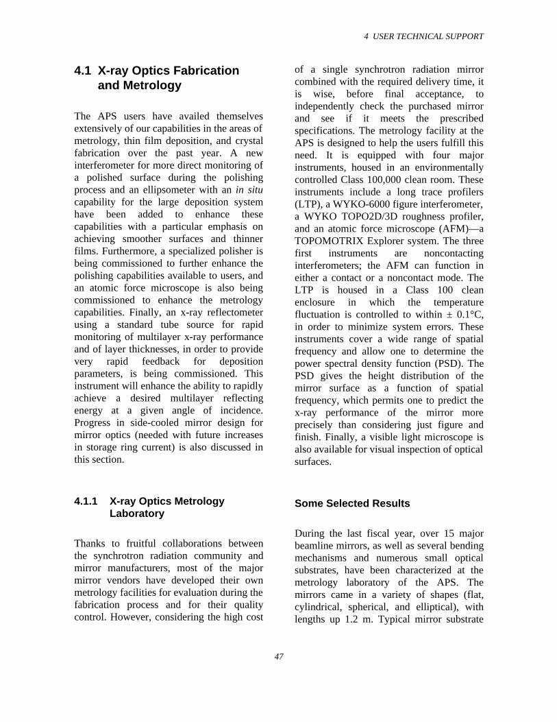
4 USER TECHNICAL SUPPORT
47
4.1 X-ray Optics Fabricationand Metrology
The APS users have availed themselvesextensively of our capabilities in the areas ofmetrology, thin film deposition, and crystalfabrication over the past year. A newinterferometer for more direct monitoring ofa polished surface during the polishingprocess and an ellipsometer with an in situcapability for the large deposition systemhave been added to enhance thesecapabilities with a particular emphasis onachieving smoother surfaces and thinnerfilms. Furthermore, a specialized polisher isbeing commissioned to further enhance thepolishing capabilities available to users, andan atomic force microscope is also beingcommissioned to enhance the metrologycapabilities. Finally, an x-ray reflectometerusing a standard tube source for rapidmonitoring of multilayer x-ray performanceand of layer thicknesses, in order to providevery rapid feedback for depositionparameters, is being commissioned. Thisinstrument will enhance the ability to rapidlyachieve a desired multilayer reflectingenergy at a given angle of incidence.Progress in side-cooled mirror design formirror optics (needed with future increasesin storage ring current) is also discussed inthis section.
4.1.1 X-ray Optics MetrologyLaboratory
Thanks to fruitful collaborations betweenthe synchrotron radiation community andmirror manufacturers, most of the majormirror vendors have developed their ownmetrology facilities for evaluation during thefabrication process and for their qualitycontrol. However, considering the high cost
of a single synchrotron radiation mirrorcombined with the required delivery time, itis wise, before final acceptance, toindependently check the purchased mirrorand see if it meets the prescribedspecifications. The metrology facility at theAPS is designed to help the users fulfill thisneed. It is equipped with four majorinstruments, housed in an environmentallycontrolled Class 100,000 clean room. Theseinstruments include a long trace profilers(LTP), a WYKO-6000 figure interferometer,a WYKO TOPO2D/3D roughness profiler,and an atomic force microscope (AFM)—aTOPOMOTRIX Explorer system. The threefirst instruments are noncontactinginterferometers; the AFM can function ineither a contact or a noncontact mode. TheLTP is housed in a Class 100 cleanenclosure in which the temperaturefluctuation is controlled to within ± 0.1°C,in order to minimize system errors. Theseinstruments cover a wide range of spatialfrequency and allow one to determine thepower spectral density function (PSD). ThePSD gives the height distribution of themirror surface as a function of spatialfrequency, which permits one to predict thex-ray performance of the mirror moreprecisely than considering just figure andfinish. Finally, a visible light microscope isalso available for visual inspection of opticalsurfaces.
Some Selected Results
During the last fiscal year, over 15 majorbeamline mirrors, as well as several bendingmechanisms and numerous small opticalsubstrates, have been characterized at themetrology laboratory of the APS. Themirrors came in a variety of shapes (flat,cylindrical, spherical, and elliptical), withlengths up 1.2 m. Typical mirror substrate
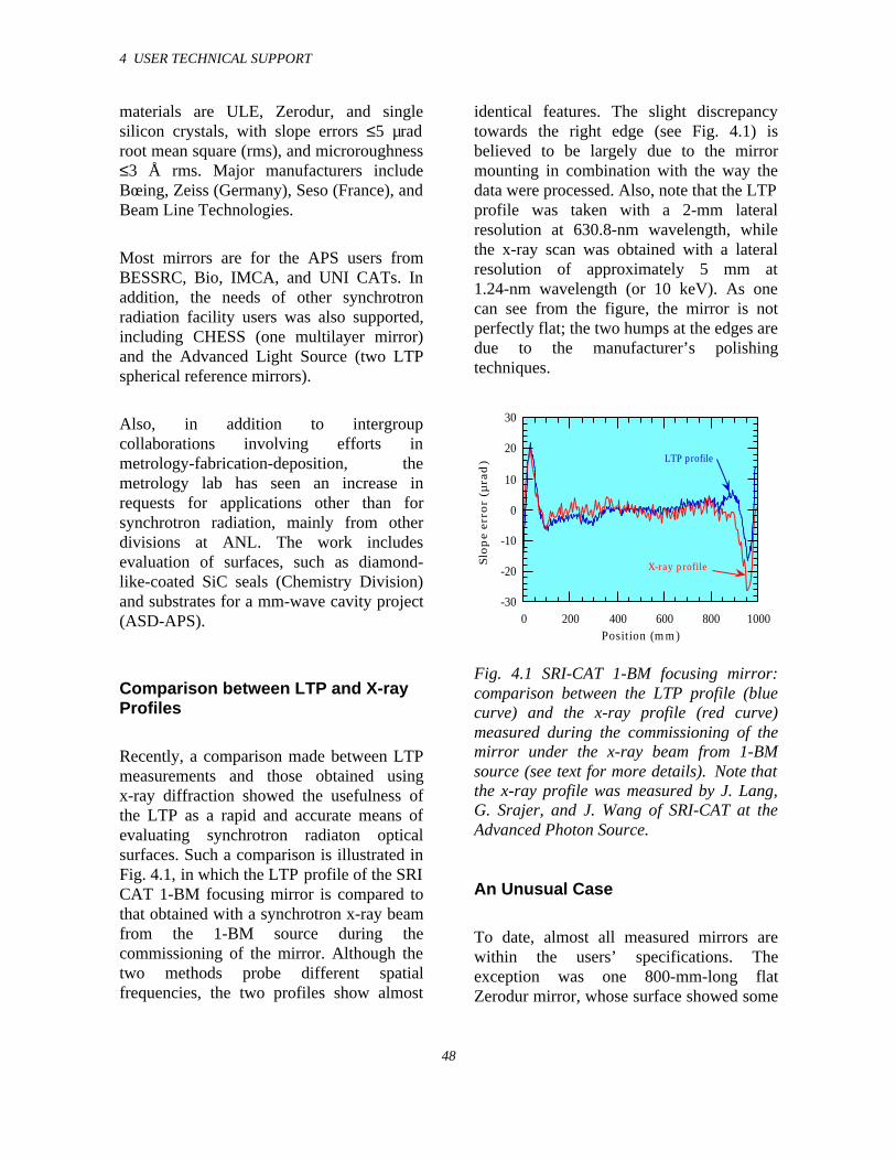
4 USER TECHNICAL SUPPORT
48
materials are ULE, Zerodur, and singlesilicon crystals, with slope errors ≤5 µradroot mean square (rms), and microroughness≤3 Å rms. Major manufacturers includeBœing, Zeiss (Germany), Seso (France), andBeam Line Technologies.
Most mirrors are for the APS users fromBESSRC, Bio, IMCA, and UNI CATs. Inaddition, the needs of other synchrotronradiation facility users was also supported,including CHESS (one multilayer mirror)and the Advanced Light Source (two LTPspherical reference mirrors).
Also, in addition to intergroupcollaborations involving efforts inmetrology-fabrication-deposition, themetrology lab has seen an increase inrequests for applications other than forsynchrotron radiation, mainly from otherdivisions at ANL. The work includesevaluation of surfaces, such as diamond-like-coated SiC seals (Chemistry Division)and substrates for a mm-wave cavity project(ASD-APS).
Comparison between LTP and X-rayProfiles
Recently, a comparison made between LTPmeasurements and those obtained usingx-ray diffraction showed the usefulness ofthe LTP as a rapid and accurate means ofevaluating synchrotron radiaton opticalsurfaces. Such a comparison is illustrated inFig. 4.1, in which the LTP profile of the SRICAT 1-BM focusing mirror is compared tothat obtained with a synchrotron x-ray beamfrom the 1-BM source during thecommissioning of the mirror. Although thetwo methods probe different spatialfrequencies, the two profiles show almost
identical features. The slight discrepancytowards the right edge (see Fig. 4.1) isbelieved to be largely due to the mirrormounting in combination with the way thedata were processed. Also, note that the LTPprofile was taken with a 2-mm lateralresolution at 630.8-nm wavelength, whilethe x-ray scan was obtained with a lateralresolution of approximately 5 mm at1.24-nm wavelength (or 10 keV). As onecan see from the figure, the mirror is notperfectly flat; the two humps at the edges aredue to the manufacturer’s polishingtechniques.
-30
-20
-10
0
10
20
30
0 200 400 600 800 1000
Slo
pe e
rro
r (µ
rad
)
Position (mm)
LTP profile
X-ray profile
Fig. 4.1 SRI-CAT 1-BM focusing mirror:comparison between the LTP profile (bluecurve) and the x-ray profile (red curve)measured during the commissioning of themirror under the x-ray beam from 1-BMsource (see text for more details). Note thatthe x-ray profile was measured by J. Lang,G. Srajer, and J. Wang of SRI-CAT at theAdvanced Photon Source.
An Unusual Case
To date, almost all measured mirrors arewithin the users’ specifications. Theexception was one 800-mm-long flatZerodur mirror, whose surface showed some
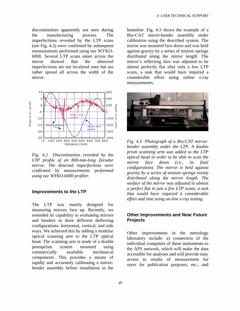
4 USER TECHNICAL SUPPORT
49
discontinuities apparently not seen duringthe manufacturing process. Theimperfections revealed by the LTP scans(see Fig. 4.2) were confirmed by subsequentmeasurements performed using our WYKO-6000. Several LTP scans taken across themirror showed that the observedimperfections are not localized ones but arerather spread all across the width of themirror.
-25
-20
-15
-10
-5
0
5
10
-400
-300
-200
-100
0
100
200
300
0 100 200 300 400 500 600 700 800
Slo
pe e
rror
(µra
d)
Heig
ht e
rror (n
m)
Distance (mm)
Slope errorprofile
Height error profile
Discontinuities
Fig. 4.2 Discontinuities revealed by theLTP profile of an 800-mm-long Zerodurmirror. The detected imperfections wereconfirmed by measurements performedusing our WYKO-6000 profiler.
Improvements to the LTP
The LTP was mainly designed formeasuring mirrors face up. Recently, weextended its capability to evaluating mirrorsand benders in three different deflectingconfigurations: horizontal, vertical, and sideways. We achieved this by adding a modularoptical scanning arm to the LTP opticalhead. The scanning arm is made of a doublepentaprism system mounted usingcommercially available mechanicalcomponents. This provides a means ofrapidly and accurately calibrating a mirror-bender assembly before installation in the
beamline. Fig. 4.3 shows the example of aBio-CAT mirror-bender assembly undercalibration using the described system. Themirror was mounted face down and was heldagainst gravity by a series of tension springsdistributed along the mirror length. Themirror’s reflecting face was adjusted to bealmost perfectly flat after only a few LTPscans, a task that would have required aconsiderable effort using online x-raymeasurements.
Fig. 4.3 Photograph of a Bio-CAT mirror-bender assembly under the LTP. A doubleprism scanning arm was added to the LTPoptical head in order to be able to scan themirror face down (i.e., its finalconfiguration). The mirror is held againstgravity by a series of tension springs evenlydistributed along the mirror length. Thesurface of the mirror was adjusted to almosta perfect flat in just a few LTP scans, a taskthat would have required a considerableeffort and time using on-line x-ray testing.
Other Improvements and Near FutureProjects
Other improvements in the metrologylaboratory include: a) connection of theindividual computers of these instruments tothe APS network, which will make the dataaccessible for analyses and will provide easyaccess to results of measurement forusers for publication purposes, etc.; and
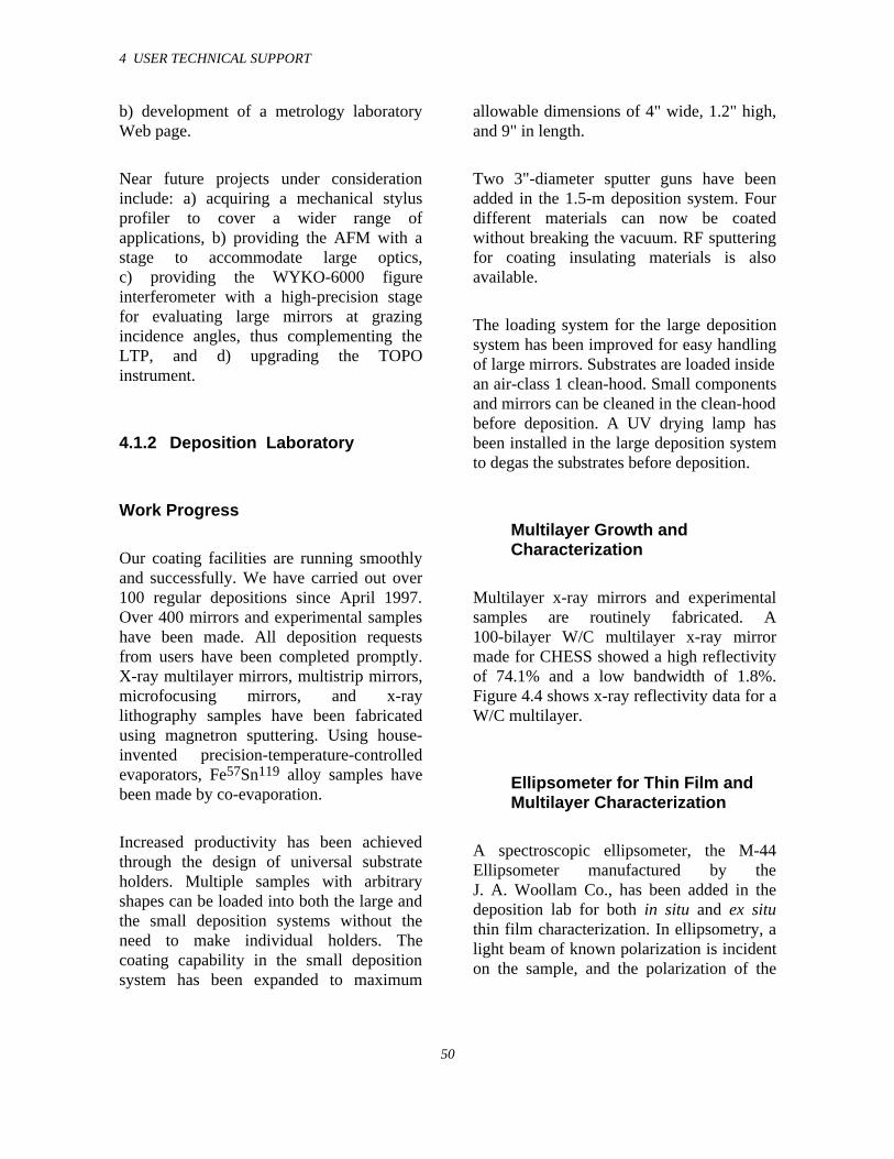
4 USER TECHNICAL SUPPORT
50
b) development of a metrology laboratoryWeb page.
Near future projects under considerationinclude: a) acquiring a mechanical stylusprofiler to cover a wider range ofapplications, b) providing the AFM with astage to accommodate large optics,c) providing the WYKO-6000 figureinterferometer with a high-precision stagefor evaluating large mirrors at grazingincidence angles, thus complementing theLTP, and d) upgrading the TOPOinstrument.
4.1.2 Deposition Laboratory
Work Progress
Our coating facilities are running smoothlyand successfully. We have carried out over100 regular depositions since April 1997.Over 400 mirrors and experimental sampleshave been made. All deposition requestsfrom users have been completed promptly.X-ray multilayer mirrors, multistrip mirrors,microfocusing mirrors, and x-raylithography samples have been fabricatedusing magnetron sputtering. Using house-invented precision-temperature-controlledevaporators, Fe57Sn119 alloy samples havebeen made by co-evaporation.
Increased productivity has been achievedthrough the design of universal substrateholders. Multiple samples with arbitraryshapes can be loaded into both the large andthe small deposition systems without theneed to make individual holders. Thecoating capability in the small depositionsystem has been expanded to maximum
allowable dimensions of 4" wide, 1.2" high,and 9" in length.
Two 3"-diameter sputter guns have beenadded in the 1.5-m deposition system. Fourdifferent materials can now be coatedwithout breaking the vacuum. RF sputteringfor coating insulating materials is alsoavailable.
The loading system for the large depositionsystem has been improved for easy handlingof large mirrors. Substrates are loaded insidean air-class 1 clean-hood. Small componentsand mirrors can be cleaned in the clean-hoodbefore deposition. A UV drying lamp hasbeen installed in the large deposition systemto degas the substrates before deposition.
Multilayer Growth andCharacterization
Multilayer x-ray mirrors and experimentalsamples are routinely fabricated. A100-bilayer W/C multilayer x-ray mirrormade for CHESS showed a high reflectivityof 74.1% and a low bandwidth of 1.8%.Figure 4.4 shows x-ray reflectivity data for aW/C multilayer.
Ellipsometer for Thin Film andMultilayer Characterization
A spectroscopic ellipsometer, the M-44Ellipsometer manufactured by theJ. A. Woollam Co., has been added in thedeposition lab for both in situ and ex situthin film characterization. In ellipsometry, alight beam of known polarization is incidenton the sample, and the polarization of the
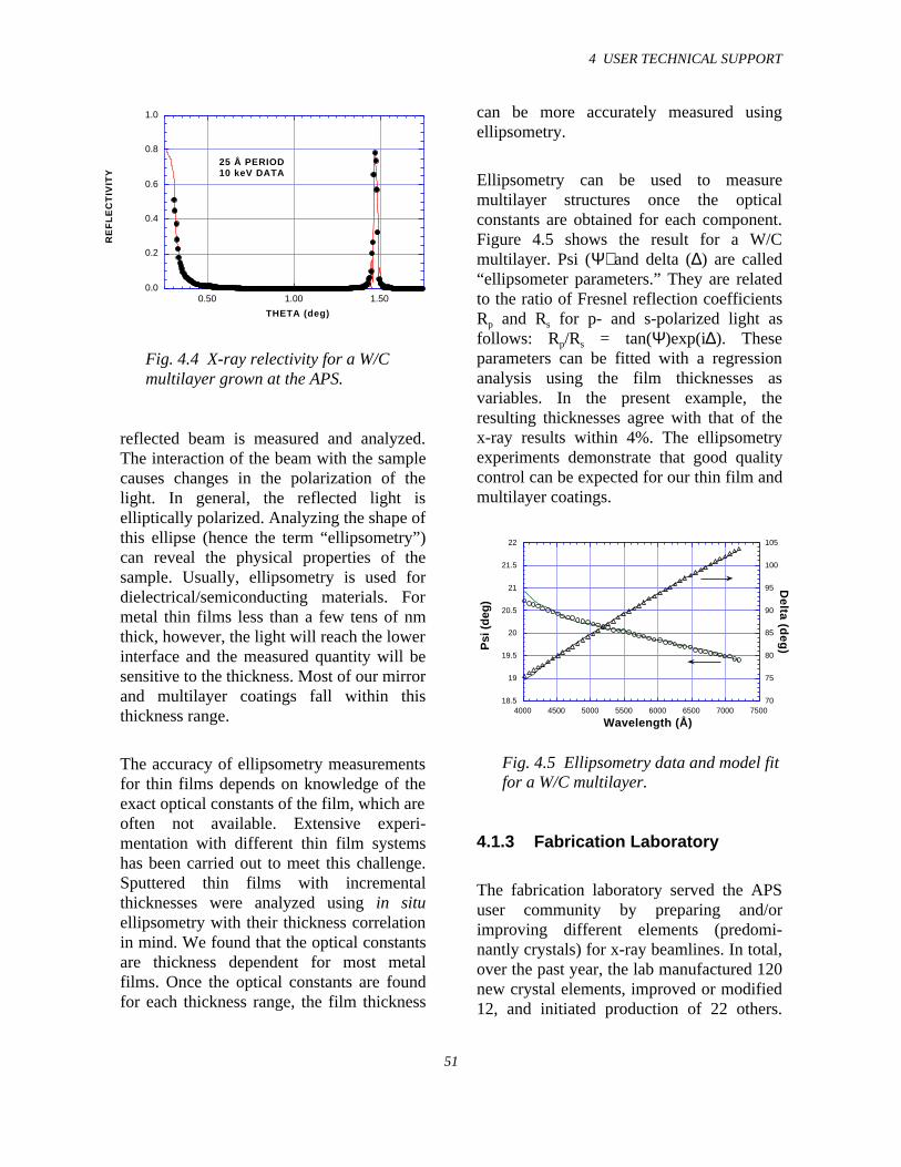
4 USER TECHNICAL SUPPORT
51
0.0
0.2
0.4
0.6
0.8
1.0
0.50 1.00 1.50
RE
FL
EC
TIV
ITY
THETA (deg)
25 Å PERIOD10 keV DATA
Fig. 4.4 X-ray relectivity for a W/Cmultilayer grown at the APS.
reflected beam is measured and analyzed.The interaction of the beam with the samplecauses changes in the polarization of thelight. In general, the reflected light iselliptically polarized. Analyzing the shape ofthis ellipse (hence the term “ellipsometry”)can reveal the physical properties of thesample. Usually, ellipsometry is used fordielectrical/semiconducting materials. Formetal thin films less than a few tens of nmthick, however, the light will reach the lowerinterface and the measured quantity will besensitive to the thickness. Most of our mirrorand multilayer coatings fall within thisthickness range.
The accuracy of ellipsometry measurementsfor thin films depends on knowledge of theexact optical constants of the film, which areoften not available. Extensive experi-mentation with different thin film systemshas been carried out to meet this challenge.Sputtered thin films with incrementalthicknesses were analyzed using in situellipsometry with their thickness correlationin mind. We found that the optical constantsare thickness dependent for most metalfilms. Once the optical constants are foundfor each thickness range, the film thickness
can be more accurately measured usingellipsometry.
Ellipsometry can be used to measuremultilayer structures once the opticalconstants are obtained for each component.Figure 4.5 shows the result for a W/Cmultilayer. Psi (Ψ) and delta (∆) are called“ellipsometer parameters.” They are relatedto the ratio of Fresnel reflection coefficientsRp and Rs for p- and s-polarized light asfollows: Rp/Rs = tan(Ψ)exp(i∆). Theseparameters can be fitted with a regressionanalysis using the film thicknesses asvariables. In the present example, theresulting thicknesses agree with that of thex-ray results within 4%. The ellipsometryexperiments demonstrate that good qualitycontrol can be expected for our thin film andmultilayer coatings.
18.5
19
19.5
20
20.5
21
21.5
22
70
75
80
85
90
95
100
105
4000 4500 5000 5500 6000 6500 7000 7500
Psi
(d
eg)
Delta (d
eg)
Wavelength (Å)
Fig. 4.5 Ellipsometry data and model fitfor a W/C multilayer.
4.1.3 Fabrication Laboratory
The fabrication laboratory served the APSuser community by preparing and/orimproving different elements (predomi-nantly crystals) for x-ray beamlines. In total,over the past year, the lab manufactured 120new crystal elements, improved or modified12, and initiated production of 22 others.
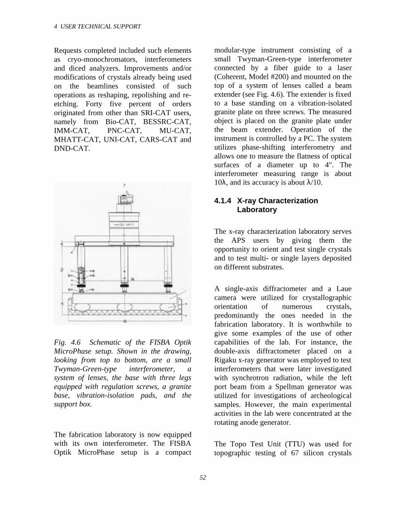
4 USER TECHNICAL SUPPORT
52
Requests completed included such elementsas cryo-monochromators, interferometersand diced analyzers. Improvements and/ormodifications of crystals already being usedon the beamlines consisted of suchoperations as reshaping, repolishing and re-etching. Forty five percent of ordersoriginated from other than SRI-CAT users,namely from Bio-CAT, BESSRC-CAT,IMM-CAT, PNC-CAT, MU-CAT,MHATT-CAT, UNI-CAT, CARS-CAT andDND-CAT.
Fig. 4.6 Schematic of the FISBA OptikMicroPhase setup. Shown in the drawing,looking from top to bottom, are a smallTwyman-Green-type interferometer, asystem of lenses, the base with three legsequipped with regulation screws, a granitebase, vibration-isolation pads, and thesupport box.
The fabrication laboratory is now equippedwith its own interferometer. The FISBAOptik MicroPhase setup is a compact
modular-type instrument consisting of asmall Twyman-Green-type interferometerconnected by a fiber guide to a laser(Coherent, Model #200) and mounted on thetop of a system of lenses called a beamextender (see Fig. 4.6). The extender is fixedto a base standing on a vibration-isolatedgranite plate on three screws. The measuredobject is placed on the granite plate underthe beam extender. Operation of theinstrument is controlled by a PC. The systemutilizes phase-shifting interferometry andallows one to measure the flatness of opticalsurfaces of a diameter up to 4". Theinterferometer measuring range is about10λ, and its accuracy is about λ/10.
4.1.4 X-ray CharacterizationLaboratory
The x-ray characterization laboratory servesthe APS users by giving them theopportunity to orient and test single crystalsand to test multi- or single layers depositedon different substrates.
A single-axis diffractometer and a Lauecamera were utilized for crystallographicorientation of numerous crystals,predominantly the ones needed in thefabrication laboratory. It is worthwhile togive some examples of the use of othercapabilities of the lab. For instance, thedouble-axis diffractometer placed on aRigaku x-ray generator was employed to testinterferometers that were later investigatedwith synchrotron radiation, while the leftport beam from a Spellman generator wasutilized for investigations of archeologicalsamples. However, the main experimentalactivities in the lab were concentrated at therotating anode generator.
The Topo Test Unit (TTU) was used fortopographic testing of 67 silicon crystals
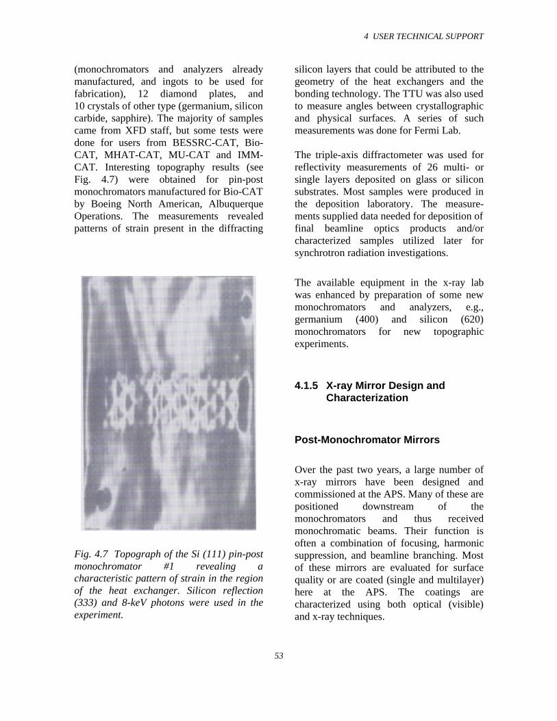
4 USER TECHNICAL SUPPORT
53
(monochromators and analyzers alreadymanufactured, and ingots to be used forfabrication), 12 diamond plates, and10 crystals of other type (germanium, siliconcarbide, sapphire). The majority of samplescame from XFD staff, but some tests weredone for users from BESSRC-CAT, Bio-CAT, MHAT-CAT, MU-CAT and IMM-CAT. Interesting topography results (seeFig. 4.7) were obtained for pin-postmonochromators manufactured for Bio-CATby Boeing North American, AlbuquerqueOperations. The measurements revealedpatterns of strain present in the diffracting
Fig. 4.7 Topograph of the Si (111) pin-postmonochromator #1 revealing acharacteristic pattern of strain in the regionof the heat exchanger. Silicon reflection(333) and 8-keV photons were used in theexperiment.
silicon layers that could be attributed to thegeometry of the heat exchangers and thebonding technology. The TTU was also usedto measure angles between crystallographicand physical surfaces. A series of suchmeasurements was done for Fermi Lab.
The triple-axis diffractometer was used forreflectivity measurements of 26 multi- orsingle layers deposited on glass or siliconsubstrates. Most samples were produced inthe deposition laboratory. The measure-ments supplied data needed for deposition offinal beamline optics products and/orcharacterized samples utilized later forsynchrotron radiation investigations.
The available equipment in the x-ray labwas enhanced by preparation of some newmonochromators and analyzers, e.g.,germanium (400) and silicon (620)monochromators for new topographicexperiments.
4.1.5 X-ray Mirror Design andCharacterization
Post-Monochromator Mirrors
Over the past two years, a large number ofx-ray mirrors have been designed andcommissioned at the APS. Many of these arepositioned downstream of themonochromators and thus receivedmonochromatic beams. Their function isoften a combination of focusing, harmonicsuppression, and beamline branching. Mostof these mirrors are evaluated for surfacequality or are coated (single and multilayer)here at the APS. The coatings arecharacterized using both optical (visible)and x-ray techniques.
4 USER TECHNICAL SUPPORT
54
For rapid characterization of mirrors andsingle- and multilayer-coated substrates(e.g., evaluation of coating quality andthickness for establishing deposition rate inthe deposition laboratory), a laboratory x-raysystem consisting of a Spellman x-raysource and a suitable beam guide has beendesigned and is being assembled. X-rays areproduced by a conventional x-ray tube (Cuor Mo targets) with a maximum power of 2kW. A horizontal beam from this source isdirected, consecutively, through a slit, amonochromator, another slit, a beamscatterer (to determine photon counts by abicron scintillation detector), and throughanother slit onto the mirror being analyzed.The mirror is placed on a Bede stage that isdesigned to fit onto a θ-2θ goniometer, andthe two in combination provide thenecessary smooth rotation and translation ofthe sample for detailed mirror surfaceanalyses. The reflected beam from thesubstrate passes through a slit and ananalyzer to a Bede detector, which has over5 orders-of-magnitude linear dynamic range.The stage, goniometer, and several of theslits are motorized for rapid sampleevaluation. Standard APS beamline dataacquisition hardware and software are usedwith a friendly computer interface on a Sunworkstation. Design of this system iscompleted, and hardware are ready and infinal stage of assembly. Additionally, acompatible but modular setup at the APSsector 2 bending magnet beamline isplanned so that samples evaluated in the labcan also be easily tested on a beamline.
Mirrors as First Optical Elements
In addition to the post-monochromatormirrors, an increasing number of APS beam-lines (at least 6) use or plan to use a mirroras the first optical element. This approach to
beamline design has been motivated, at leastin part, by the success in the design ofsimple high-heat-load mirrors at the APSand by their reliability and ease of operationestablished over the past two years. As anexample, the contact-cooled high-heat-loadmirror at the sector 2 undulator beamline ofthe APS has been operating for two yearswithout any mirror-related downtime. Thepreliminary thermal and structuralperformance of this mirror at commissioningand during subsequent observationsindicates a tangential rms slope error ofabout 2-4 µrad (Khounsary et al., 1998); aprecise measurement of the mirror has beenplanned for this summer (1998).
Plans have also been made for precise re-evaluation of this mirror using ‘pink’ beamradiation this summer. For this, we havedesigned a cooled composite slit arrayconsisting of a thin copper plate with thirtyholes, each 60 µm in diameter and located at300-µm center-to-center intervals, maskinganother slit array of thirty 30-µm holesconfigured in a thin tantalum plate. Thesetwo plates are aligned, with the one havinglarger holes acting as a thermal shield for thesecond plate. Pink undulator beam reflectedfrom the mirror passes through the slit arrayand is recorded on a charge-coupled device(CCD). Transient and steady-state tangentialslope errors in the mirror under various heatload conditions are mapped from the shiftsin the slit images on the CCD camera.
Another attribute of the mirror-firstbeamline design is the ability to use a water-cooled monochromator downstream of themirror. A simple contact-cooledmonochromator—dubbed U-monochromatorfor its U-shaped cross section—wasdesigned, installed, and evaluated. Bothearly evaluations (Lee et al., 1997) andrecent experience indicate that this contact-
4 USER TECHNICAL SUPPORT
55
cooled monochromator is capable ofcomfortably handling post-mirror undulatorbeam.
Mirror Characterization Using anin situ LTP
Another set of measurements aimed atevaluating mirror performance under high-heat-load x-ray beam was made using anin situ long trace profiler developed at theAPS sector 2-ID beamline in collaborationwith Brookhaven National Laboratory. Inthis setup, a laser beam scans the length of acontact-cooled high-heat-load 200-mm-longmirror to determine its transient and steady-state slope errors. Preliminary results(Takacs and Randall, 1998) indicate athermally induced slope error of about7 µrad at steady-state conditions and athermal time constant of about 10 minutes.These are in excellent agreement withdesign predications made earlier (Khounsaryand Yun, 1996).
X-ray Mirror Design for Higher BeamPowers
As new generations of vacuum chambersmake smaller undulator gap openingspossible and as enhancement in storage ringcapabilities make ring operation at higherbeam currents possible, the ramifications ofusing mirrors as first optical elements withsubstantially higher power x-ray beams needto be examined. A program aimed atdeveloping mirrors for higher heat loads hasled to a design that is expected to meet therequirements.
With closer undulator gap and/or higherstorage beam current, the heat load on
mirrors used as the first optical element willbe substantially increased. At a gap openingof 11.5 mm, a typical 1.2-m-long mirrorlocated at about 30 m from the source at a0.15° angle with respect to the x-ray beam(reflecting photons up to 35 keV with a Ptcoating) receives about 1.2 kW of power anda peak heat load of about 0.4 W/mm2. Themaximum temperature and rms slope errorsare 45°C and 2 µrad, respectively. At acloser 10.5-mm gap and a hypothetical300-mA storage ring current, the incidentheat load on the same mirror will be 5 kWwith a peak heat flux of 1.5 W/mm2. Theincreased heat load lead to highertemperature, higher slope errors, and higherstress in the mirror. While moderate heatload increases (up to about 30%) on thepresent mirrors can be tolerated at the costof about 50% increase in slope error, moresignificant increases can lead tounacceptable temperature, slope errors, andstresses.
We have embarked on designing anothersimple contact-cooled mirror aimed athandling, with acceptable performance, theabove hypothetical heat load. The keyfeatures of this mirror design are(1) introduction of a pair of notches in themirror substrate (see Fig. 4.8) for a moreeffective thermal moment balance in thesubstrate, (2) replacement of the indium foilused as interstitial material (between thecopper cooling and silicon mirror) withIn/Ga eutectic for a more efficient heattransfer, and (3) an increase in the coolingblock width to reduce substrate temperature.Preliminary analyses indicate thatincorporation of these three features wouldlead to a mirror with under 5-µrad slopeerror with a maximum temperature of about80°C for the above hypothetical power load.Stress levels in the mirror are high, and aprototype should be made and tested undersimulated heat-load conditions.
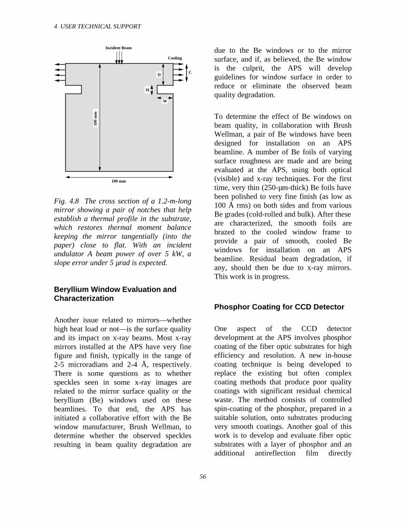
4 USER TECHNICAL SUPPORT
56
100 mm
Incident Beam
100
mm
Cooling
CD
W
H
Fig. 4.8 The cross section of a 1.2-m-longmirror showing a pair of notches that helpestablish a thermal profile in the substrate,which restores thermal moment balancekeeping the mirror tangentially (into thepaper) close to flat. With an incidentundulator A beam power of over 5 kW, aslope error under 5 µrad is expected.
Beryllium Window Evaluation andCharacterization
Another issue related to mirrors—whetherhigh heat load or not—is the surface qualityand its impact on x-ray beams. Most x-raymirrors installed at the APS have very finefigure and finish, typically in the range of2-5 microradians and 2-4 Å, respectively.There is some questions as to whetherspeckles seen in some x-ray images arerelated to the mirror surface quality or theberyllium (Be) windows used on thesebeamlines. To that end, the APS hasinitiated a collaborative effort with the Bewindow manufacturer, Brush Wellman, todetermine whether the observed specklesresulting in beam quality degradation are
due to the Be windows or to the mirrorsurface, and if, as believed, the Be windowis the culprit, the APS will developguidelines for window surface in order toreduce or eliminate the observed beamquality degradation.
To determine the effect of Be windows onbeam quality, in collaboration with BrushWellman, a pair of Be windows have beendesigned for installation on an APSbeamline. A number of Be foils of varyingsurface roughness are made and are beingevaluated at the APS, using both optical(visible) and x-ray techniques. For the firsttime, very thin (250-µm-thick) Be foils havebeen polished to very fine finish (as low as100 Å rms) on both sides and from variousBe grades (cold-rolled and bulk). After theseare characterized, the smooth foils arebrazed to the cooled window frame toprovide a pair of smooth, cooled Bewindows for installation on an APSbeamline. Residual beam degradation, ifany, should then be due to x-ray mirrors.This work is in progress.
Phosphor Coating for CCD Detector
One aspect of the CCD detectordevelopment at the APS involves phosphorcoating of the fiber optic substrates for highefficiency and resolution. A new in-housecoating technique is being developed toreplace the existing but often complexcoating methods that produce poor qualitycoatings with significant residual chemicalwaste. The method consists of controlledspin-coating of the phosphor, prepared in asuitable solution, onto substrates producingvery smooth coatings. Another goal of thiswork is to develop and evaluate fiber opticsubstrates with a layer of phosphor and anadditional antireflection film directly
4 USER TECHNICAL SUPPORT
57
deposited on them to make simple,integrated substrates for use in x-raydetectors.
4.2 Beamline Controls andData Acquisition
The XFD beamline-controls effort has twocomplementary missions of approximatelyequal priority: (1) to develop general-purpose control and data-acquisitionsoftware that all APS CATs can use andprovide technical support to CATdevelopers; (2) to implement software andcomputer-related infrastructure (network,file server, workstations, printers, etc.) forthe SRI-CAT beamlines and laboratories.This arrangement implies that SRI-CATusers test software for the rest of the facilityand provide much of the feedback directingits development. Our contact with other APSusers is generally indirect, through theirdevelopers.
Nearly all APS beamlines run XFD-developed software, though theimplementations vary from CAT to CAT.Some CATs run virtually the same softwareas does SRI-CAT, from user interfacethrough low-level drivers; others run ourlow-level and middle-level software in theirVME crates and supplement or replace ouruser-interface layer with their own customsoftware. The APS Beamline ControlsCollaboration, which includes developersrepresenting all APS CATs, chose EPICS asthe basis for beamline software developmentin part because it allows for this kind offlexibility of implementation.
EPICS does not guarantee this flexibility,however; nor does the mere implementationof support for a device (e.g., an optical
table) or a technique (e.g., on-the-flyscanning) in EPICS software guarantee thatthe support can be used facility-wide. Asidefrom the quality of a software module, thelayer in which it is implemented determineswhether it can be run by higher-levelsoftware and whether it can run lower-levelsoftware. Software that can do both providesthe greatest flexibility, and consequentlymuch of our focus is on this kind ofsoftware.
Most of XFD's beamline-softwaredevelopment effort is in server-sidesoftware—the low-level and middle-levelsoftware that runs in VME crates—asopposed to client-side software that runsmostly on workstations. Roughly half of ourdevelopment is of driver software, whichinteracts directly with hardware and clearlymust run on the server side. But much of therest could be done either in server or inclient software, and we choose server-sidedevelopment whenever possible—some-times even when client-side would be amore natural choice—because anythingimplemented in server software can be usedby all CATs, regardless of their choices ofclient software, workstation type, andoperating system.
The past year's development effort hasfocused on five general areas: improvementsin scan and data-storage software; supportfor message-based devices; support forremote beamline operation; support for newdevices; and exploratory studies of software,hardware, and techniques that may one daybecome useful in beamline control.
4 USER TECHNICAL SUPPORT
58
4.2.1 Improvements in Scan Software
The EPICS scan software described in lastyear's report worked around a fundamentallylimited completion detector—themechanism for determining whenpositioners or detectors have completed theirmovements or acquisition. The oldcompletion detector could be fooled bynetwork latency into thinking that a set ofpositioners was done if the “busy” and“done” messages from one positioner werereceived before the “busy” message fromanother was received. The completiondetector also required developers tomaintain a list of all slow devices eligiblefor scans. This list had to be modifiable atrun time, and the implementation of thatrequirement limited scan speeds to a fewtens of data points per second. Finally, thecompletion detector was confusing to newusers and a frequent source of trouble.
The new scan software takes advantage ofrecent improvements in EPICS that allow itto track the flow of execution through acomplex assembly of software moduleslinked together at run time, and to reportcompletion of the entire assembly to themodule that initiated the operation. Wemodified the scan software to use this newcapability as a completion detector. Most ofour custom records, databases, and sequenceprograms also required modification, tofollow the new rules that allow thiscompletion detector to function properly.
The resulting system allows users to scanany correctly implemented device withoutidentifying it in advance to the scansoftware, is unaffected by normal networklatency, and is nearly an order of magnitudefaster than the old system. Scans can nowacquire several hundred data points persecond, significantly extending the range
beyond which custom hardware (e.g.,waveform generators and multichannelscalers) is required. One type of run-timecoordination supported by the oldcompletion detector is no longer supporteddirectly, although users sophisticatedenough to require that type of coordinationcan program the new scan software to runthe old completion detector as a pseudopositioner.
4.2.2 Improvements in Data-Storageand Display Software
The data-storage and display softwaredescribed in last year’s report consisted of asingle client program running on aworkstation. That arrangement wasexpedient and got us through a few difficultyears, but it put storage and displaypriorities in conflict, and resulted in acomplex event loop that made the softwaredifficult to maintain end extend. Also, thedual-use program allowed users to deleteonline data, and one user did thisunintentionally.
Now, data storage is handled by a clientrunning in the VME crate that writesdirectly to the file server. Normallypriviledged users can no longer delete rawdata, and data storage continues throughworkstation reboots, license-managerrestarts, etc.
Display software for online data is nowhandled by a separate program with noresponsibilities other than display. Theprogram is still somewhat complicatedbecause it must monitor real-time data usingEPICS calls and read recently stored datafrom data files. (For scans of two or more
4 USER TECHNICAL SUPPORT
59
dimensions, both real-time and stored datamust be displayed.)
For long-term data storage, and forexporting data to users' home facilities, theplan is still to use the Hierarchical DataFormat (HDF) based file format agreed onby the APS Beamline ControlsCollaboration and supported by third partybrowsers and some data-analysis packages.This format, now called NeXus, has evolvedsignificantly in recent years, and theperformance of HDF has improved as well,though we still cannot write NeXus files fastenough to keep up with real-time dataacquisition.
4.2.3 Support for Message-BasedDevices
Visiting APS users occasionally bringspecial-purpose serial or GPIB devices withthem and need to integrate support for thesedevices into the control system. CARS-CATdeveloped generic modules to send andreceive strings to/from serial and GPIBports, but users still have to format and parsethe strings. Until recently, that task requiredcustom client software, and the resultingdevice support could not be used by server-side software. We filled part of the needwith boot-time configurable modules thatserver software could call, but the result wasunsatisfactory, arcane, and difficult tomaintain.
This year we bridged the gap by addingstring support to EPICS run-timeprogrammable calculation software (withwhich many users already are familiar).Now run-time programmable support formessage-based devices behaves just likenative EPICS device-support software, is
useable both by client-side and by server-side software, and can easily beprogrammed by users. This means we canfully integrate selected functions of mostserial or GPIB devices into the controlsystem in a few minutes.
4.2.4 Support for Remote BeamlineOperation
EPICS has always provided for sharedlocal/remote beamline control. Thecapability has thus far been used mostly bydevelopers for technical support and by asmall number of users to do simple thingslike checking the progress of very long-running scans from home.
This year we found a user for serious remotebeamline operation. We wrote software tomanipulate a remotely controllable videocamera using an unmodified Web browser,modified some public-domain software tosend selected video streams (also to anunmodified browser), installed standardEPICS client software on a workstation atthe University of Florida, and demonstratedrunning a beamline from there to anaudience of developers, users, and programdirectors.
4.2.5 Other Highlights
Over the past year, we responded to roughly2300 tech-support requests. This number issignificantly lower than last year’s, and therequests are qualitatively much different.We received relatively few requests forhardware information, since most of thatinformation is now on our Web pages. Mostof the CAT developers are well up theEPICS learning curve by now, and our Web-
4 USER TECHNICAL SUPPORT
60
based software documentation is also muchimproved. The requests we do get generallyare more complex than in previous yearsand, on average, take much longer to handle.
We performed system and networkadministration for six beamlines and relatedlabs. The control systems supported by ourgroup now comprise 27 VME crates,approximately 60 computers, and 12printers.
We hosted the second internationalNOBUGS (New Opportunities for BetterUser Group Software) workshop forsoftware developers from synchrotron-radiation and neutron-scattering facilities.Of 106 participants, 49 were from Argonne,including 31 from the APS.
We have largely taken over EPICS buildsfor the APS project and distribution of mostEPICS software for the EPICScollaboration. We also have beguncontributing to the maintenance of Hideossoftware and VxWorks board-supportsoftware on both of which most APSbeamline-control systems depend.
In addition, we have:
• Developed support for two newoptical-table geometries and nowallow for fewer than six degrees offreedom
• Delivered 110 motor-signal interfaceboards to CATs, bringing the total to300
• Converted all SRI-CAT workstationsfrom the SunOS operating system toSolaris
• Solved the input-termination prob-lem in the StepPack motor-driverinterface board and fabricatedsufficient patch kits for all APSbeamlines
• Developed hardware and softwaresupport for servo motors, piezo-drivers, and the Keithley 2000scanning digital multimeter
4.3 References
Khounsary, A. M., W. Yun, B. Lai, I.McNulty, Z. Cai (1998) “Performance ofside-cooled high-heat load mirrors,” paperpresented at the SPIE Conference onAdvances in Mirror Technology for X-ray,Synchrotron, and Laser ApplicationsConference, San Diego, July 20, 1998.
Khounsary, A. M. and W. Yun (1996) Rev.Sci. Instrum. 67 (9) CD ROM.
Lee, W-K., P.B. Fernandez, A. Khounsary,W. Yun, and E. Trakhtenberg (1997) SPIEProc. Vol. 3151, 208-215.
Takacs, P. and K. Randall (1998) “Mirrordistortion measurements with an in situLTP,” paper presented at the SPIEConference on Advances in MirrorTechnology for X-ray, Synchrotron, andLaser Applications Conference, San Diego,July 20, 1998.
5 R&D IN SUPPORT OF OPERATIONS
61
5.1 Radiation SourcePerformance
5.1.1 Undulator A Performance
Twenty-two insertion devices are nowinstalled in the storage ring (Table 5.1).During 1998, we acquired considerableoperating experience with these devices. Thefirst measurements made on undulator A atthe APS were reported previously (Cai et al.,1996; Ilinski et al., 1996). This year,additional diagnostics and analyses wereperformed on the sector 8 undulator (UA2).
The UA2 undulator is a standard 3.3-cm-period APS undulator A (Dejus et al., 1994),which was positioned downstream from thecenter of the straight section at sector 8. Thediagnostics included the angular-spectralmeasurements of the undulator radiation todetermine the undulator radiation absolutespectral flux and the particle beamdivergence. The undulator diagnostics setupincluded a pinhole slit assembly to reducethe incident power and to define the angularacceptance and a crystal spectrometer forabsolute spectral flux measurements (Ilinskiet al., 1996). All components were mountedon a standard APS optical table with five
Table 5.1. Insertion devices installed atthe APS as of August 1998.
Type Number
3.3-cm-period undulator (undulator A) 175.5-cm-period undulator 1
2.7-cm-period undulator 11.8-cm-period undulator 18.5-cm-period wiggler 1elliptical multipole wiggler 1
degrees of freedom, so that the setup axiscould be adjusted to the axis of the undulatorradiation and transverse scans could beperformed. The setup was installed in thefirst optical enclosure (FOE) after two250 µm Be windows.
The results of the undulator UA2 diagnosticsshowed that the undulator spectrummeasured at different gaps (18.0, 18.5,19.0 mm) is close to what one could expect.At a gap of 18.5 mm, the measuredundulator flux is in a good agreement withthe calculated flux (as shown in Fig. 5.1).Flux calculations were performed using themeasured undulator UA2 magnetic fieldprofile at a gap of 18.5 mm and the values ofthe particle beam divergence, particle energyspread, and distance to the source.Comparisons were done for the standardstorage ring lattice and for the lattice withlow vertical beta function.
For the standard lattice that was used in1997 (βx = 14.2 m, βy = 10.0 m, coupling =2-4%), the measured absolute flux for thefirst and third harmonics at a gap of18.5 mm was within 1% of the calculatedundulator flux. The measured flux of thefifth harmonic was 15% less than calculated.For the low-beta lattice that has been usedsince February 1998 (βx = 16.6 m, βy =3.0 m, coupling = 1.2-1.7%), on-axis fluxdensity of the first harmonic decreased to92% of that for the standard latticeconfiguration. The flux density did notchange significantly because the horizontaldivergence dominates the vertical when two-dimensional convolution is performed.Nevertheless, the larger vertical divergencefor the low-beta lattice configuration couldrequire increasing the size of the verticalaperture of the apparatus to obtain the sametotal photon flux as for the standard latticeconfiguration.
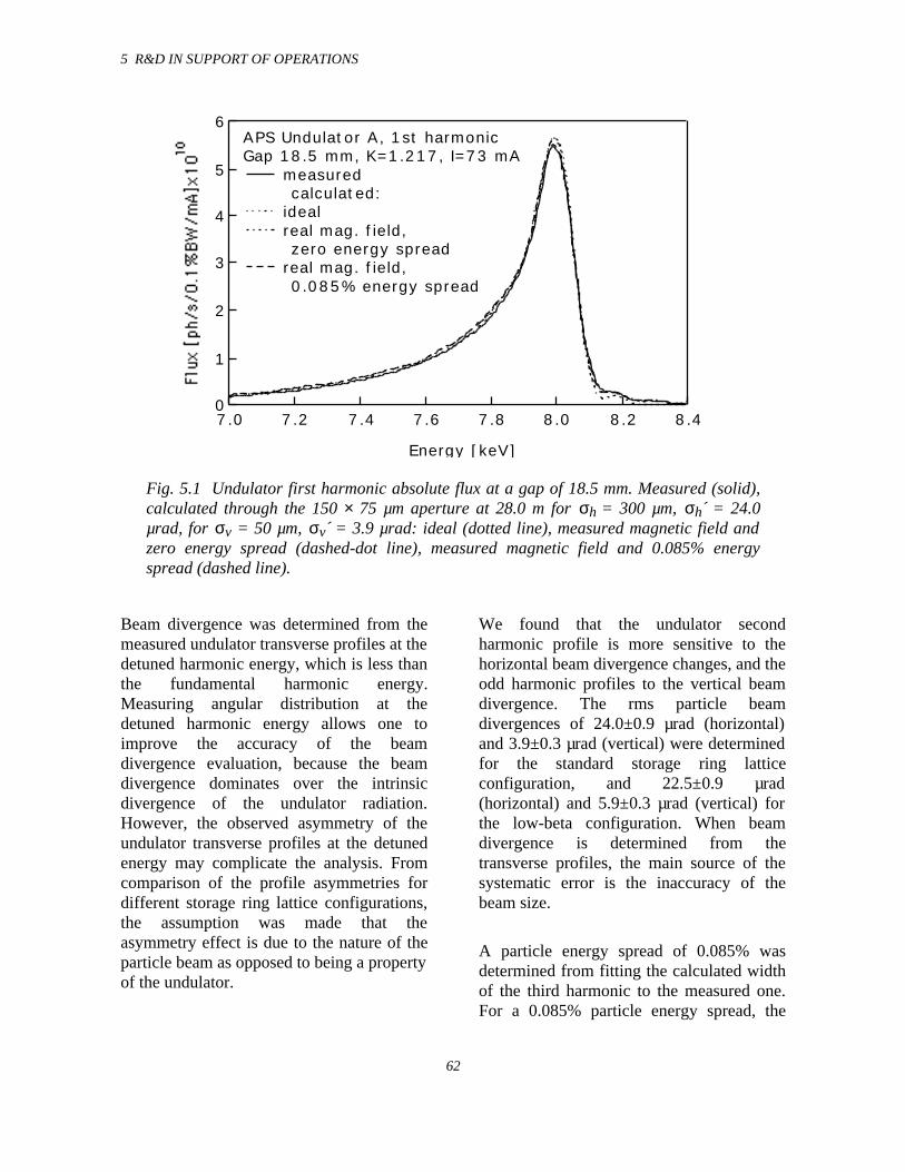
5 R&D IN SUPPORT OF OPERATIONS
62
6
5
4
3
2
1
08.48.28.07.87.67.47.27.0
Energy [keV]
APS Undulator A, 1st harmonicGap 18.5 mm, K=1.217, I=73 mA
measured calculated:
ideal real mag. field,
zero energy spread real mag. field,
0.085% energy spread
Fig. 5.1 Undulator first harmonic absolute flux at a gap of 18.5 mm. Measured (solid),calculated through the 150 × 75 µm aperture at 28.0 m for σh = 300 µm, σh´ = 24.0µrad, for σv = 50 µm, σv´ = 3.9 µrad: ideal (dotted line), measured magnetic field andzero energy spread (dashed-dot line), measured magnetic field and 0.085% energyspread (dashed line).
Beam divergence was determined from themeasured undulator transverse profiles at thedetuned harmonic energy, which is less thanthe fundamental harmonic energy.Measuring angular distribution at thedetuned harmonic energy allows one toimprove the accuracy of the beamdivergence evaluation, because the beamdivergence dominates over the intrinsicdivergence of the undulator radiation.However, the observed asymmetry of theundulator transverse profiles at the detunedenergy may complicate the analysis. Fromcomparison of the profile asymmetries fordifferent storage ring lattice configurations,the assumption was made that theasymmetry effect is due to the nature of theparticle beam as opposed to being a propertyof the undulator.
We found that the undulator secondharmonic profile is more sensitive to thehorizontal beam divergence changes, and theodd harmonic profiles to the vertical beamdivergence. The rms particle beamdivergences of 24.0±0.9 µrad (horizontal)and 3.9±0.3 µrad (vertical) were determinedfor the standard storage ring latticeconfiguration, and 22.5±0.9 µrad(horizontal) and 5.9±0.3 µrad (vertical) forthe low-beta configuration. When beamdivergence is determined from thetransverse profiles, the main source of thesystematic error is the inaccuracy of thebeam size.
A particle energy spread of 0.085% wasdetermined from fitting the calculated widthof the third harmonic to the measured one.For a 0.085% particle energy spread, the
5 R&D IN SUPPORT OF OPERATIONS
63
harmonic widths of the calculated first andfifth harmonics do not exactly match themeasured widths of the undulatorharmonics. The calculated full width halfmaximum (FWHM) of the fifth harmonic is330 eV compared to 366 eV for themeasured value.
The diagnostics of undulator A at sector 8demonstrated once more that theperformance of the standard APS ID is quiteclose to that of an ideal undulator. Also,readily available ID diagnostics equipmentwith capabilities to measure spectral andspatial radiation distributions proved to bean essential tool at this user facility.
5.1.2 Elliptical Multipole WigglerPerformance
Over the past decade, synchrotron radiationhas increasingly been used to probe themagnetic properties of materials. Thesemeasurements have generally involved themodulation (or analysis) of the polarizationof the incident (or scattered/absorbed) x-raybeams. Techniques, such as circularmagnetic x-ray dichroism, core levelphotoemission, and magnetic Comptonscattering, which utilize circularly polarizedphotons, have attracted particular interest.Because circularly polarized photons coupledifferently with the magnetic moment of anatom than do neutrons, they are able toprovide unique magnetic information notgenerally accessible by neutron techniques.The development of circularly polarizedx-ray diffraction and spectroscopytechniques, however, has been hampered bythe lack of efficient sources. Measurementsthus far have been primarily taken utilizingoff-axis synchrotron radiation from abending magnet source, which greatly limitsincident x-ray flux. The available flux is
particularly important for these types ofexperiments, due to the inherently smallnature of the magnetic x-ray cross section.To increase the available circularlypolarized x-ray flux, an elliptical wigglerwas first proposed and built by Yamamotoet al. (1989). This device consisted of aseries of dipole magnets supplemented by ahorizontal magnetic field for tilting particletrajectories up and down to obtain circularlypolarized radiation along the axis of thewiggler.
Efficient sources of circularly polarizedx-rays should provide both the highestpossible flux and degree of circularpolarization (Pc). Recently, an ellipticalmultipole wiggler (EMW) has beendesigned, built, and operated on the 11-IDbeamline of the APS to provide just suchcharacteristics. A comparison of the EMWwith other techniques used for theproduction of circularly polarized x-rays hasbeen given (Lang et al., 1996). The EMWprovides a helicity-switchable (<10 Hz),highly polarized, high flux source of hardx-rays (5 < E < 200 keV). The firstmeasurements characterizing theperformance of this device between 10 and100 keV have been performed. A detaileddescription of the EMW facility at the APShas been previously reported (Montano etal., 1995), and only a brief description willbe given here. The EMW is based on adesign by Gluskin et al. (1995); it has16 periods and a period length of 16 cm. The24-mm wiggler gap yields a horizontaldeflection parameter (Ky) of 14.6,corresponding to a critical energy of 32 keVand a total wiggler power of 5.4 kW at100 mA. An electromagnet controls thevertical deflection parameter (Kx), whichcan be continuously varied from 0.0 to 1.3.The use of the electromagnet allows forrapid helicity reversal up to 10 Hz. The
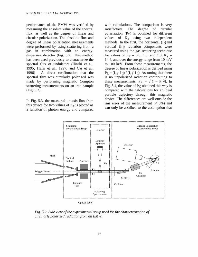
5 R&D IN SUPPORT OF OPERATIONS
64
performance of the EMW was verified bymeasuring the absolute value of the spectralflux, as well as the degree of linear andcircular polarization. The absolute flux anddegree of linear polarization measurementswere performed by using scattering from agas in combination with an energy-dispersive detector (Fig. 5.2). This methodhas been used previously to characterize thespectral flux of undulators (Ilinski et al.,1995; Hahn et al., 1997; and Cai et al.,1996) A direct confirmation that thespectral flux was circularly polarized wasmade by performing magnetic Comptonscattering measurements on an iron sample(Fig. 5.2).
In Fig. 5.3, the measured on-axis flux fromthis device for two values of Kx is plotted asa function of photon energy and compared
with calculations. The comparison is verysatisfactory. The degree of circularpolarization (PC) is obtained for differentvalues of Kx using two independentmethods. In the first, the horizontal (I ) andvertical (I⊥) radiation components weremeasured using the gas-scattering techniquefor values of Kx = 0.8, 1.0, and 1.3, Ky =14.4, and over the energy range from 10 keVto 100 keV. From these measurements, thedegree of linear polarization is derived usingPL = (I − I⊥) / (I + I⊥). Assuming that thereis no unpolarized radiation contributing tothese measurements, PΧ = √[1 – PL2]. InFig. 5.4, the value of PC obtained this way iscompared with the calculations for an idealparticle trajectory through this magneticdevice. The differences are well outside therms error of the measurement (< 5%) andcan only be ascribed to the assumption that
Wiggler beam
Entrance Slit
Slit
DetectorAperture
Conical Pinhole
Detector
IonChamber
Si (111)
ScatteringSpectrometer
Circular Polarization Measurement Setup
Aperture
Detector
Mask
Sample
Optical Table
B
φ
α
Cu filter
Scattering Measurement Setup
Fig. 5 2 Side view of the experimental setup used for the characterization ofcircularly polarized radiation from an EMW.
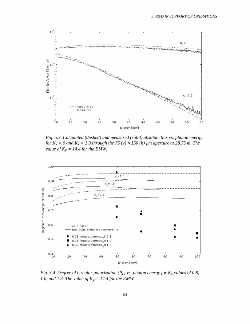
5 R&D IN SUPPORT OF OPERATIONS
65
2
3
4
567
107
2
3
4
567
108
2
3
4
567
109
6055504540353025201510
Energy [keV]
Kx=0
Kx=1.3
calculated measured
Fig. 5.3 Calculated (dashed) and measured (solid) absolute flux vs. photon energyfor Kx = 0 and Kx = 1.3 through the 75 (v) × 150 (h) µm aperture at 28.75 m. Thevalue of Ky = 14.4 for the EMW.
1.0
0.9
0.8
0.7
0.6
0.5
0.4100908070605040302010
Energy [keV]
Kx=0.8
Kx=1.0
Kx=1.3
calculated gas scattering measurements
MCS measurements, Kx=0.8 MCS measurements, Kx=1.0 MCS measurements, Kx=1.3
Fig. 5.4 Degree of circular polarization (Pc) vs. photon energy for Kx values of 0.8,1.0, and 1.3. The value of Ky = 14.4 for the EMW.
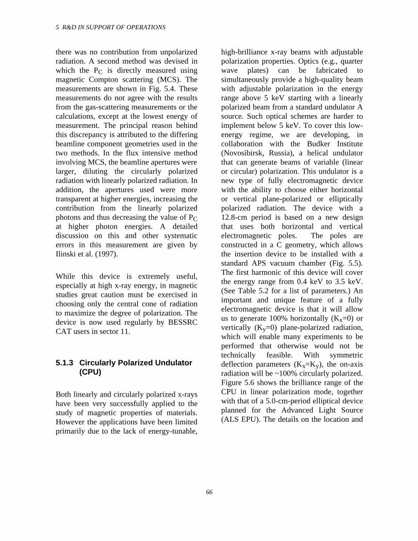
5 R&D IN SUPPORT OF OPERATIONS
66
there was no contribution from unpolarizedradiation. A second method was devised inwhich the PC is directly measured usingmagnetic Compton scattering (MCS). Themeasurements are shown in Fig. 5.4. Thesemeasurements do not agree with the resultsfrom the gas-scattering measurements or thecalculations, except at the lowest energy ofmeasurement. The principal reason behindthis discrepancy is attributed to the differingbeamline component geometries used in thetwo methods. In the flux intensive methodinvolving MCS, the beamline apertures werelarger, diluting the circularly polarizedradiation with linearly polarized radiation. Inaddition, the apertures used were moretransparent at higher energies, increasing thecontribution from the linearly polarizedphotons and thus decreasing the value of PCat higher photon energies. A detaileddiscussion on this and other systematicerrors in this measurement are given byIlinski et al. (1997).
While this device is extremely useful,especially at high x-ray energy, in magneticstudies great caution must be exercised inchoosing only the central cone of radiationto maximize the degree of polarization. Thedevice is now used regularly by BESSRCCAT users in sector 11.
5.1.3 Circularly Polarized Undulator(CPU)
Both linearly and circularly polarized x-rayshave been very successfully applied to thestudy of magnetic properties of materials.However the applications have been limitedprimarily due to the lack of energy-tunable,
high-brilliance x-ray beams with adjustablepolarization properties. Optics (e.g., quarterwave plates) can be fabricated tosimultaneously provide a high-quality beamwith adjustable polarization in the energyrange above 5 keV starting with a linearlypolarized beam from a standard undulator Asource. Such optical schemes are harder toimplement below 5 keV. To cover this low-energy regime, we are developing, incollaboration with the Budker Institute(Novosibirsk, Russia), a helical undulatorthat can generate beams of variable (linearor circular) polarization. This undulator is anew type of fully electromagnetic devicewith the ability to choose either horizontalor vertical plane-polarized or ellipticallypolarized radiation. The device with a12.8-cm period is based on a new designthat uses both horizontal and verticalelectromagnetic poles. The poles areconstructed in a C geometry, which allowsthe insertion device to be installed with astandard APS vacuum chamber (Fig. 5.5).The first harmonic of this device will coverthe energy range from 0.4 keV to 3.5 keV.(See Table 5.2 for a list of parameters.) Animportant and unique feature of a fullyelectromagnetic device is that it will allowus to generate 100% horizontally (Kx=0) orvertically (Ky=0) plane-polarized radiation,which will enable many experiments to beperformed that otherwise would not betechnically feasible. With symmetricdeflection parameters (Kx=Ky), the on-axisradiation will be ~100% circularly polarized.Figure 5.6 shows the brilliance range of theCPU in linear polarization mode, togetherwith that of a 5.0-cm-period elliptical deviceplanned for the Advanced Light Source(ALS EPU). The details on the location and
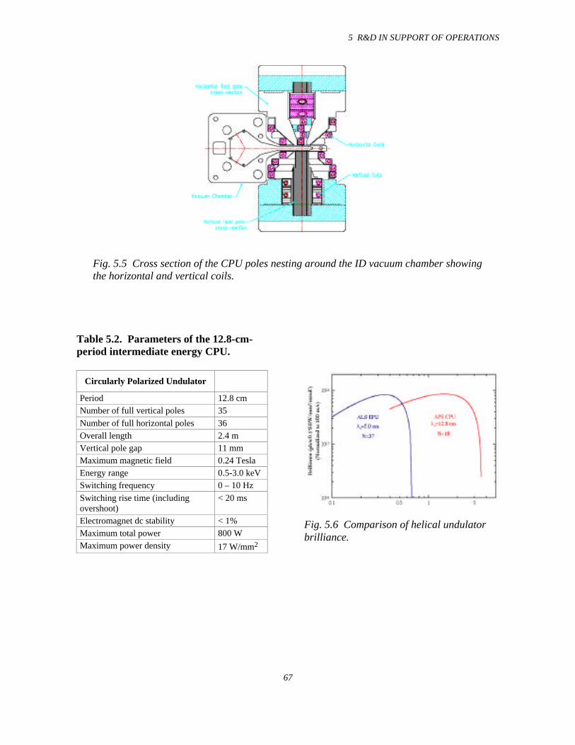
5 R&D IN SUPPORT OF OPERATIONS
67
Fig. 5.5 Cross section of the CPU poles nesting around the ID vacuum chamber showingthe horizontal and vertical coils.
Table 5.2. Parameters of the 12.8-cm-period intermediate energy CPU.
Circularly Polarized Undulator
Period 12.8 cmNumber of full vertical poles 35
Number of full horizontal poles 36Overall length 2.4 mVertical pole gap 11 mmMaximum magnetic field 0.24 TeslaEnergy range 0.5-3.0 keVSwitching frequency 0 – 10 Hz
Switching rise time (includingovershoot)
< 20 ms
Electromagnet dc stability < 1%Maximum total power 800 WMaximum power density 17 W/mm2
Fig. 5.6 Comparison of helical undulatorbrilliance.
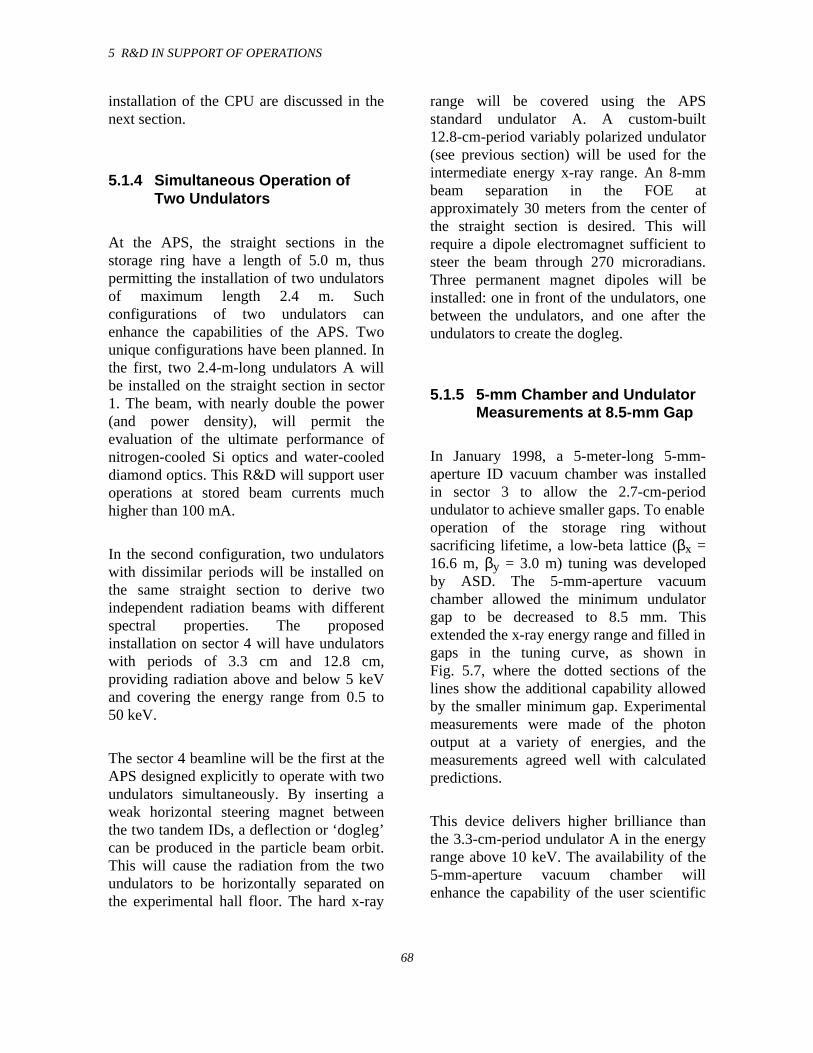
5 R&D IN SUPPORT OF OPERATIONS
68
installation of the CPU are discussed in thenext section.
5.1.4 Simultaneous Operation ofTwo Undulators
At the APS, the straight sections in thestorage ring have a length of 5.0 m, thuspermitting the installation of two undulatorsof maximum length 2.4 m. Suchconfigurations of two undulators canenhance the capabilities of the APS. Twounique configurations have been planned. Inthe first, two 2.4-m-long undulators A willbe installed on the straight section in sector1. The beam, with nearly double the power(and power density), will permit theevaluation of the ultimate performance ofnitrogen-cooled Si optics and water-cooleddiamond optics. This R&D will support useroperations at stored beam currents muchhigher than 100 mA.
In the second configuration, two undulatorswith dissimilar periods will be installed onthe same straight section to derive twoindependent radiation beams with differentspectral properties. The proposedinstallation on sector 4 will have undulatorswith periods of 3.3 cm and 12.8 cm,providing radiation above and below 5 keVand covering the energy range from 0.5 to50 keV.
The sector 4 beamline will be the first at theAPS designed explicitly to operate with twoundulators simultaneously. By inserting aweak horizontal steering magnet betweenthe two tandem IDs, a deflection or ‘dogleg’can be produced in the particle beam orbit.This will cause the radiation from the twoundulators to be horizontally separated onthe experimental hall floor. The hard x-ray
range will be covered using the APSstandard undulator A. A custom-built12.8-cm-period variably polarized undulator(see previous section) will be used for theintermediate energy x-ray range. An 8-mmbeam separation in the FOE atapproximately 30 meters from the center ofthe straight section is desired. This willrequire a dipole electromagnet sufficient tosteer the beam through 270 microradians.Three permanent magnet dipoles will beinstalled: one in front of the undulators, onebetween the undulators, and one after theundulators to create the dogleg.
5.1.5 5-mm Chamber and UndulatorMeasurements at 8.5-mm Gap
In January 1998, a 5-meter-long 5-mm-aperture ID vacuum chamber was installedin sector 3 to allow the 2.7-cm-periodundulator to achieve smaller gaps. To enableoperation of the storage ring withoutsacrificing lifetime, a low-beta lattice (βx =16.6 m, βy = 3.0 m) tuning was developedby ASD. The 5-mm-aperture vacuumchamber allowed the minimum undulatorgap to be decreased to 8.5 mm. Thisextended the x-ray energy range and filled ingaps in the tuning curve, as shown inFig. 5.7, where the dotted sections of thelines show the additional capability allowedby the smaller minimum gap. Experimentalmeasurements were made of the photonoutput at a variety of energies, and themeasurements agreed well with calculatedpredictions.
This device delivers higher brilliance thanthe 3.3-cm-period undulator A in the energyrange above 10 keV. The availability of the5-mm-aperture vacuum chamber willenhance the capability of the user scientific
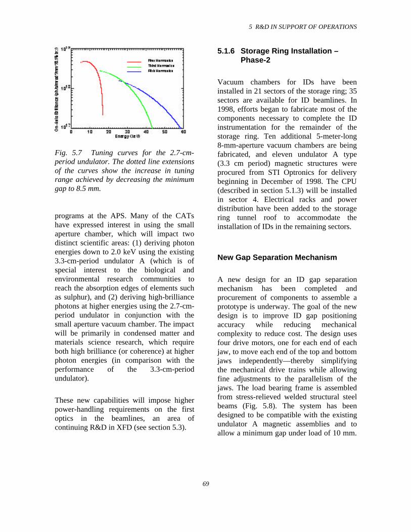
5 R&D IN SUPPORT OF OPERATIONS
69
Fig. 5.7 Tuning curves for the 2.7-cm-period undulator. The dotted line extensionsof the curves show the increase in tuningrange achieved by decreasing the minimumgap to 8.5 mm.
programs at the APS. Many of the CATshave expressed interest in using the smallaperture chamber, which will impact twodistinct scientific areas: (1) deriving photonenergies down to 2.0 keV using the existing3.3-cm-period undulator A (which is ofspecial interest to the biological andenvironmental research communities toreach the absorption edges of elements suchas sulphur), and (2) deriving high-brilliancephotons at higher energies using the 2.7-cm-period undulator in conjunction with thesmall aperture vacuum chamber. The impactwill be primarily in condensed matter andmaterials science research, which requireboth high brilliance (or coherence) at higherphoton energies (in comparison with theperformance of the 3.3-cm-periodundulator).
These new capabilities will impose higherpower-handling requirements on the firstoptics in the beamlines, an area ofcontinuing R&D in XFD (see section 5.3).
5.1.6 Storage Ring Installation –Phase-2
Vacuum chambers for IDs have beeninstalled in 21 sectors of the storage ring; 35sectors are available for ID beamlines. In1998, efforts began to fabricate most of thecomponents necessary to complete the IDinstrumentation for the remainder of thestorage ring. Ten additional 5-meter-long8-mm-aperture vacuum chambers are beingfabricated, and eleven undulator A type(3.3 cm period) magnetic structures wereprocured from STI Optronics for deliverybeginning in December of 1998. The CPU(described in section 5.1.3) will be installedin sector 4. Electrical racks and powerdistribution have been added to the storagering tunnel roof to accommodate theinstallation of IDs in the remaining sectors.
New Gap Separation Mechanism
A new design for an ID gap separationmechanism has been completed andprocurement of components to assemble aprototype is underway. The goal of the newdesign is to improve ID gap positioningaccuracy while reducing mechanicalcomplexity to reduce cost. The design usesfour drive motors, one for each end of eachjaw, to move each end of the top and bottomjaws independently—thereby simplifyingthe mechanical drive trains while allowingfine adjustments to the parallelism of thejaws. The load bearing frame is assembledfrom stress-relieved welded structural steelbeams (Fig. 5.8). The system has beendesigned to be compatible with the existingundulator A magnetic assemblies and toallow a minimum gap under load of 10 mm.
5 R&D IN SUPPORT OF OPERATIONS
70
Fig. 5.8 New gap separation mechanism forundulator A.
The frame is extremely rigid; finite elementcalculations show a deflection of less than3 µm when the 3.3-cm-period magneticstructure is closed to an 8.5-mm gap.
5.1.7 Collaborations
BESSY Chambers
For several years, the ID group of XFD hascollaborated with the staff of the BerlinerElektronenspeicherring-Gesellschaft furSynchrotronstrahlung (BESSY), located inBerlin, Germany, to design and fabricate IDvacuum chambers for the BESSY II project.These chambers used the innovativetechnology developed by the APS for smallaperture vacuum chambers. In 1998 thisproject was completed; ten chambers weredelivered to Berlin for installation into thestorage ring. One of these chambers isshown in Fig. 5.9.
DESY Chambers
The Deutsches Elektronen-Synchrotron(DESY), located in Hamburg, Germany, isbuilding a vacuum ultraviolet (VUV) FELbased on the TESLA Test Facility linearaccelerator. The APS is an official partner inthis project. Towards this objective, XFD isdesigning and fabricating the small-apertureextruded-aluminum vacuum chambers thatwill be used for the FEL undulators. Seven9.5-mm-aperture chambers, each 4.516 mlong, are being built. Figure 5.10 shows thefirst chamber after preliminary machining.The project is expected to be completed inthe spring of 1999, and the FEL tests will beperformed during the fall of 1999. The FELoperated at 1 GeV is expected to produceradiation with a wavelength of 70 nm.
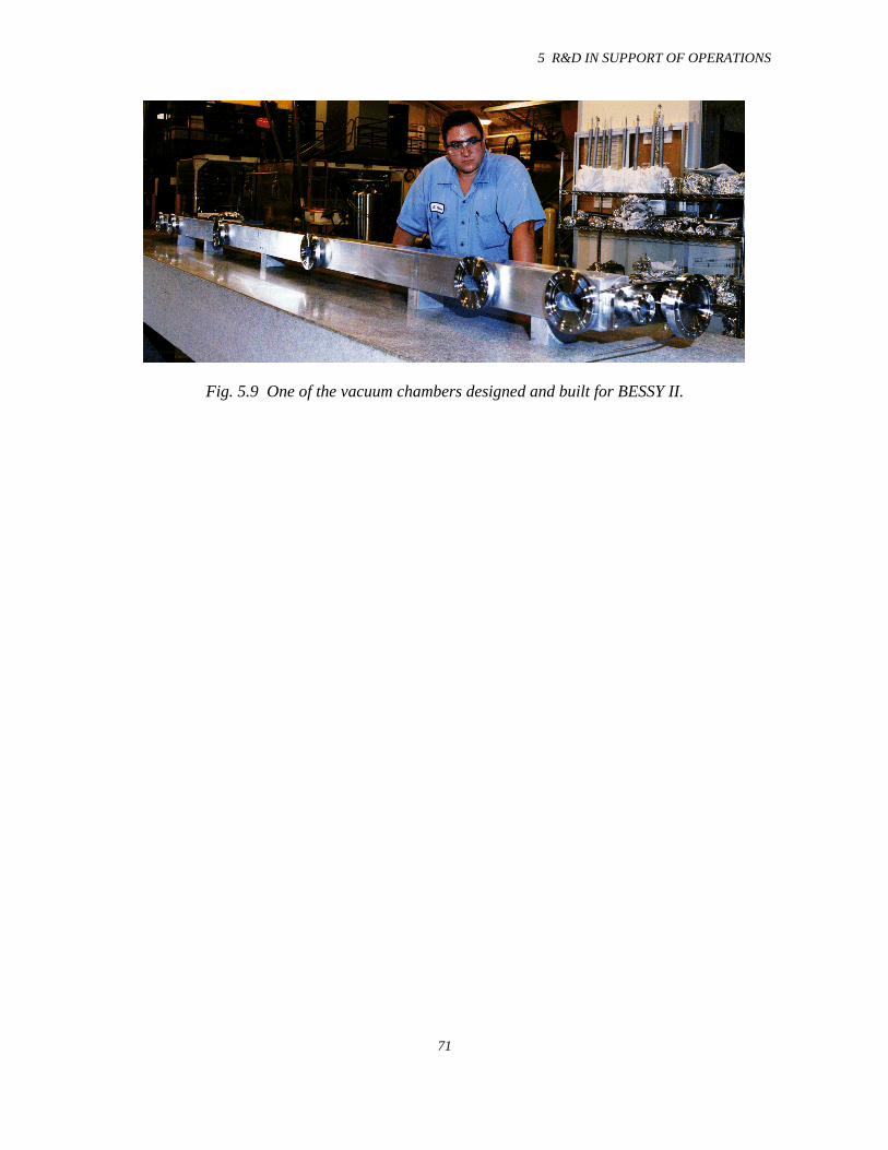
5 R&D IN SUPPORT OF OPERATIONS
71
Fig. 5.9 One of the vacuum chambers designed and built for BESSY II.
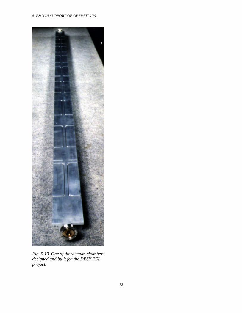
5 R&D IN SUPPORT OF OPERATIONS
72
Fig. 5.10 One of the vacuum chambersdesigned and built for the DESY FELproject.
5 R&D IN SUPPORT OF OPERATIONS
70
5.2 Beamline Engineering
5.2.1 Introduction
The beamline engineering effort during thefacility construction years focused on thedesign, construction, and commissioning ofvarious beamline components, whichincluded the beamline front ends, theexperiment enclosures; various experiment-specific components, etc. These efforts havepaid off as measured by the successfuloperation of user beamlines. During the pastyear, the focus of the staff working on theR&D in support of beamline engineering hasmoved to evaluation of the performance ofbeamline components, leading to new
5 R&D IN SUPPORT OF OPERATIONS
71
concepts and developments for fututrebeamlines. Attention was also given to thenew requirements, present and future, tomeet goals of the user scientific programs.
One of the major shortcomings in themanufacture of various beamlinecomponents by the vendors was their limitedsuccess in brazing Glidcop to variousmetals. The staff working on beamlineengineering hence developed variousbrazing technologies and capabilities tobridge the gap so that users couldsuccessfully begin their scientific programs.In the next section, the brazing furnaces andtheir capabilities are described.
In order to meet new requirements of theusers, conceptual and design changes in thefront ends are needed in the newerbeamlines planned for construction. Thesedesigns and their new capabilities aredescribed in section 5.2.3.
Finally in section 5.2.4, a description of botha laser Doppler displacement meter and anangular encoder with sub-nanoradian
sensitivity required for high-resolutionmonochromators is provided. These uniquedesigns will have a much wider applicationin the future as users plan moresophisticated experiments.
5.2.2 Brazing Capabilities forBeamline Components
Small Brazing System
A new metallurgical brazing system hasbeen developed by the BeamlineEngineering Group that is used primarily forbrazing small samples and heat transferexperimental tubes. Due to the small size ofthe system, it is ideal for brazing smallcomponents at a fraction of the costcompared to one of our larger brazingsystems. The capability supports specialneeds of the users, as well as unique R&Dneeds for the beamline engineering effort.The small system size allows for rapidheating and cooling, and consequentlysamples can be processed in a minimal
5 R&D IN SUPPORT OF OPERATIONS
72
amount of time. A Carbolite three-zoneclam-shell-type resistance heating furnace isused as the heat source. The three zones areindependently controllable via threetemperature controllers remotely located onthe system control module. A 2-inch (insidediameter) by 4-foot-long clear quartz tubeequipped with quartz feedthrough end capsis used for the brazing chamber.
Vacuum Furnace for LargeComponent Brazing
Another brazing system has been developedto provide state-of-the-art brazingcapabilities for future front-end andbeamline components. This new systemincorporates a significant number ofimprovements over our older system toprovide several levels of automated controlover the brazing process. As before, a thin-walled high-temperature material tube wasused for the brazing chamber to minimizeheating and cooling times, an essentialrequirement for brazing Glidcop®. AHastolloy-X rolled and welded tube with a7 1/2 inch inside diameter and 15 feet longwas selected due to the superior high-temperature properties of this material. Thelong tube length provides the flexibility tobraze very long parts.
A 15-kW three-zone Lindburg® clam-shell-type resistance heating furnace is used as theheat source and is mounted with precisionslides on a rail system to allow easymovement of the furnace along the tube. Thefurnace is coupled via a magnet lock to aprecision ball screw drive system, which iscontrollable from a remote keypad andjoystick. The controller can be easilyprogrammed from a PC to provide anycombination of motion and positioning
5 R&D IN SUPPORT OF OPERATIONS
73
referenced from a “home” position with amaximum speed of 2 inches per second. Themotion control system provides thecapability to oscillate the oven over longparts to achieve repeatable uniform heatingand also provides an absolute positionreference for repeating previous braze runs.The magnet lock can be instantly de-energized via a large emergency stop buttonto decouple the oven from the drive system.
As with the older brazing system, the threeoven zones can be individually controlledfrom remote temperature controllers,however, an “auto-tune” feature has beenadded to eliminate the need to calibrate thebraze run. Another key feature of the newsystem is a fully automated pump and purgecontroller. Prior to brazing, the chamberneeds to be pumped and purged in arepetitive fashion with a high purity inertgas in order to “wash” contamination fromthe chamber walls and the component. Ifdone manually, this process is timeconsuming. The pump and purge systemwill automatically perform this process, andthe number of cycles and pumping times canbe changed via keypads on the controller.The gas delivery system accommodates fourseparate gas sources, typically Ar, He, andtwo N2 supplies. The microbleed circuit isused during the brazing process to achieve areduced atmosphere in the chamber, and thequenching circuit is used to rapidly coolbrazed parts. All of these circuits haveprecision flow-control valves and flowmeters for repeatable gas delivery rates. Thevacuum aspects of the new brazing systemare far superior to the system usedpreviously in this effort.
During the year, several braze techniques forjoining stainless steel to GlidCop® weredeveloped. These techniques were used tofabricate several fixed masks that are now
installed in the front ends. In addition, someof the components for the SPring-8 frontends were designed and fabricated, whichinvolved various specialized brazing jobs.
5-ID Ratchet-Wall Collimator TubeExaminations
In section 2.6.6, a detailed description of thesector 5 front-end problem was provided.This single incidence in which the ratchet-wall collimator was distorted requiredindependent examination. The collimator,when isolated for study, showedconsiderable residual distortion.
The collimator itself was displaced by asmuch as 9 mm in the shield wall, with abouta 6-mm bend in the tube. When it wasexamined in the laboratory, the residualbend was only 2.1 mm. In order tounderstand the source of this distortion, adetailed examination was performed.Corrosion was found in the lead shotsurrounding the collimator. Chemical testresults showed that most of the corrosionwas aluminum oxide deposited on the leadshot. Lead oxides and concrete were alsofound, although the amounts were small incomparison.
A bend test was designed to simulatepossible conditions in the shield wall. Asshown in Fig. 5.11, approximately 36,000 Ndisplaced the tube 7 mm and left a residualbend of 3.2 mm. In the actual front ends, thecause of such force is unclear; however, thepressure would not have been generated ifboth ends of the collimator were notclamped. As described in section 2.6.6, allratchet-wall collimators were modified as apreventative measure to allow for changes inthe collimator dimensions. The chemical
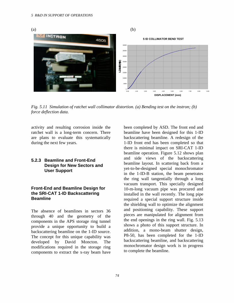
5 R&D IN SUPPORT OF OPERATIONS
74
(a) (b)
Fig. 5.11 Simulation of ratchet wall collimator distortion. (a) Bending test on the instron; (b)force deflection data.
activity and resulting corrosion inside theratchet wall is a long-term concern. Thereare plans to evaluate this systematicallyduring the next few years.
5.2.3 Beamline and Front-EndDesign for New Sectors andUser Support
Front-End and Beamline Design forthe SRI-CAT 1-ID BackscatteringBeamline
The absence of beamlines in sectors 36through 40 and the geometry of thecomponents in the APS storage ring tunnelprovide a unique opportunity to build abackscattering beamline on the 1-ID source.The concept for this unique capability wasdeveloped by David Moncton. Themodifications required in the storage ringcomponents to extract the x-ray beam have
been completed by ASD. The front end andbeamline have been designed for this 1-IDbackscattering beamline. A redesign of the1-ID front end has been completed so thatthere is minimal impact on SRI-CAT 1-IDbeamline operation. Figure 5.12 shows planand side views of the backscatteringbeamline layout. In scattering back from ayet-to-be-designed special monochromatorin the 1-ID-B station, the beam penetratesthe ring wall tangentially through a longvacuum transport. This specially designed10-m-long vacuum pipe was procured andinstalled in the wall recently. The long piperequired a special support structure insidethe shielding wall to optimize the alignmentand positioning capability. These supportpieces are manipulated for alignment fromthe end openings in the ring wall. Fig. 5.13shows a photo of this support structure. Inaddition, a mono-beam shutter design,P8-50, has been completed for the 1-IDbackscattering beamline, and backscatteringmonochromator design work is in progressto complete the beamline.
5 ID COLLIMATOR BEND TEST
0
5000
10000
15000
20000
25000
30000
35000
40000
0.00 1.00 2.00 3.00 4.00 5.00 6.00 7.00 8.00 9.00
DISPLACEMENT (mm)
LO
AD
(N
)
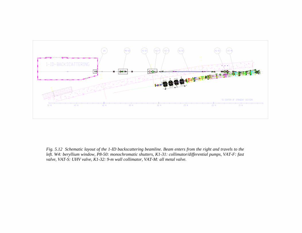
Fig. 5.12 Schematic layout of the 1-ID backscattering beamline. Beam enters from the right and travels to theleft. W4: beryllium window, P8-50: monochromatic shutters, K1-31: collimator/differential pumps, VAT-F: fastvalve, VAT-S: UHV valve, K1-32: 9-m wall collimator, VAT-M: all metal valve.
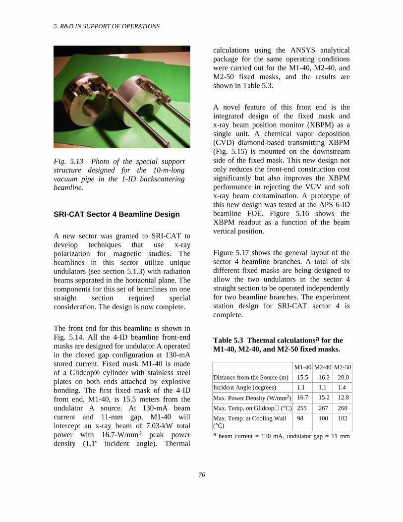
5 R&D IN SUPPORT OF OPERATIONS
76
Fig. 5.13 Photo of the special supportstructure designed for the 10-m-longvacuum pipe in the 1-ID backscatteringbeamline.
SRI-CAT Sector 4 Beamline Design
A new sector was granted to SRI-CAT todevelop techniques that use x-raypolarization for magnetic studies. Thebeamlines in this sector utilize uniqueundulators (see section 5.1.3) with radiationbeams separated in the horizontal plane. Thecomponents for this set of beamlines on onestraight section required specialconsideration. The design is now complete.
The front end for this beamline is shown inFig. 5.14. All the 4-ID beamline front-endmasks are designed for undulator A operatedin the closed gap configuration at 130-mAstored current. Fixed mask M1-40 is madeof a Glidcop® cylinder with stainless steelplates on both ends attached by explosivebonding. The first fixed mask of the 4-IDfront end, M1-40, is 15.5 meters from theundulator A source. At 130-mA beamcurrent and 11-mm gap, M1-40 willintercept an x-ray beam of 7.03-kW totalpower with 16.7-W/mm2 peak powerdensity (1.1o incident angle). Thermal
calculations using the ANSYS analyticalpackage for the same operating conditionswere carried out for the M1-40, M2-40, andM2-50 fixed masks, and the results areshown in Table 5.3.
A novel feature of this front end is theintegrated design of the fixed mask andx-ray beam position monitor (XBPM) as asingle unit. A chemical vapor deposition(CVD) diamond-based transmitting XBPM(Fig. 5.15) is mounted on the downstreamside of the fixed mask. This new design notonly reduces the front-end construction costsignificantly but also improves the XBPMperformance in rejecting the VUV and softx-ray beam contamination. A prototype ofthis new design was tested at the APS 6-IDbeamline FOE. Figure 5.16 shows theXBPM readout as a function of the beamvertical position.
Figure 5.17 shows the general layout of thesector 4 beamline branches. A total of sixdifferent fixed masks are being designed toallow the two undulators in the sector 4straight section to be operated independentlyfor two beamline branches. The experimentstation design for SRI-CAT sector 4 iscomplete.
Table 5.3 Thermal calculationsa for theM1-40, M2-40, and M2-50 fixed masks.
M1-40 M2-40 M2-50
Distance from the Source (m) 15.5 16.2 20.0
Incident Angle (degrees) 1.1 1.1 1.4
Max. Power Density (W/mm2) 16.7 15.2 12.8
Max. Temp. on Glidcop (°C) 255 267 260
Max. Temp. at Cooling Wall(°C)
98 100 102
a beam current = 130 mA, undulator gap = 11 mm
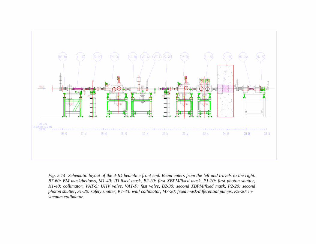
Fig. 5.14 Schematic layout of the 4-ID beamline front end. Beam enters from the left and travels to the right.B7-60: BM mask/bellows, M1-40: ID fixed mask, B2-20: first XBPM/fixed mask, P1-20: first photon shutter,K1-40: collimator, VAT-S: UHV valve, VAT-F: fast valve, B2-30: second XBPM/fixed mask, P2-20: secondphoton shutter, S1-20: safety shutter, K1-43: wall collimator, M7-20: fixed mask/differential pumps, K5-20: in-vacuum collimator.
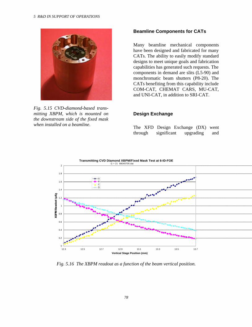
5 R&D IN SUPPORT OF OPERATIONS
78
Fig. 5.15 CVD-diamond-based trans-mitting XBPM, which is mounted onthe downstream side of the fixed maskwhen installed on a beamline.
Beamline Components for CATs
Many beamline mechanical componentshave been designed and fabricated for manyCATs. The ability to easily modify standarddesigns to meet unique goals and fabricationcapabilities has generated such requests. Thecomponents in demand are slits (L5-90) andmonchromatic beam shutters (P8-20). TheCATs benefiting from this capability includeCOM-CAT, CHEMAT CARS, MU-CAT,and UNI-CAT, in addition to SRI-CAT.
Design Exchange
The XFD Design Exchange (DX) wentthrough significant upgrading and
Transmitting CVD Diamond XBPM/Fixed Mask Test at 6-ID-FOE
0
0.2
0.4
0.6
0.8
1
1.2
1.4
1.6
1.8
2
12.3 12.5 12.7 12.9 13.1 13.3 13.5 13.7
Vertical Stage Position (mm)
XB
PM
Re
ad
ou
t (µ
A)
ABCD
G = 21 98040705.dat
Fig. 5.16 The XBPM readout as a function of the beam vertical position.
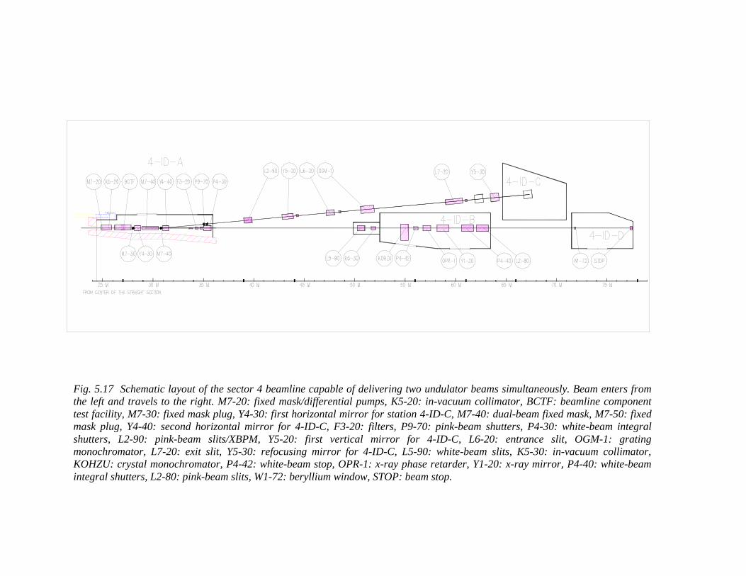
Fig. 5.17 Schematic layout of the sector 4 beamline capable of delivering two undulator beams simultaneously. Beam enters fromthe left and travels to the right. M7-20: fixed mask/differential pumps, K5-20: in-vacuum collimator, BCTF: beamline componenttest facility, M7-30: fixed mask plug, Y4-30: first horizontal mirror for station 4-ID-C, M7-40: dual-beam fixed mask, M7-50: fixedmask plug, Y4-40: second horizontal mirror for 4-ID-C, F3-20: filters, P9-70: pink-beam shutters, P4-30: white-beam integralshutters, L2-90: pink-beam slits/XBPM, Y5-20: first vertical mirror for 4-ID-C, L6-20: entrance slit, OGM-1: gratingmonochromator, L7-20: exit slit, Y5-30: refocusing mirror for 4-ID-C, L5-90: white-beam slits, K5-30: in-vacuum collimator,KOHZU: crystal monochromator, P4-42: white-beam stop, OPR-1: x-ray phase retarder, Y1-20: x-ray mirror, P4-40: white-beamintegral shutters, L2-80: pink-beam slits, W1-72: beryllium window, STOP: beam stop.
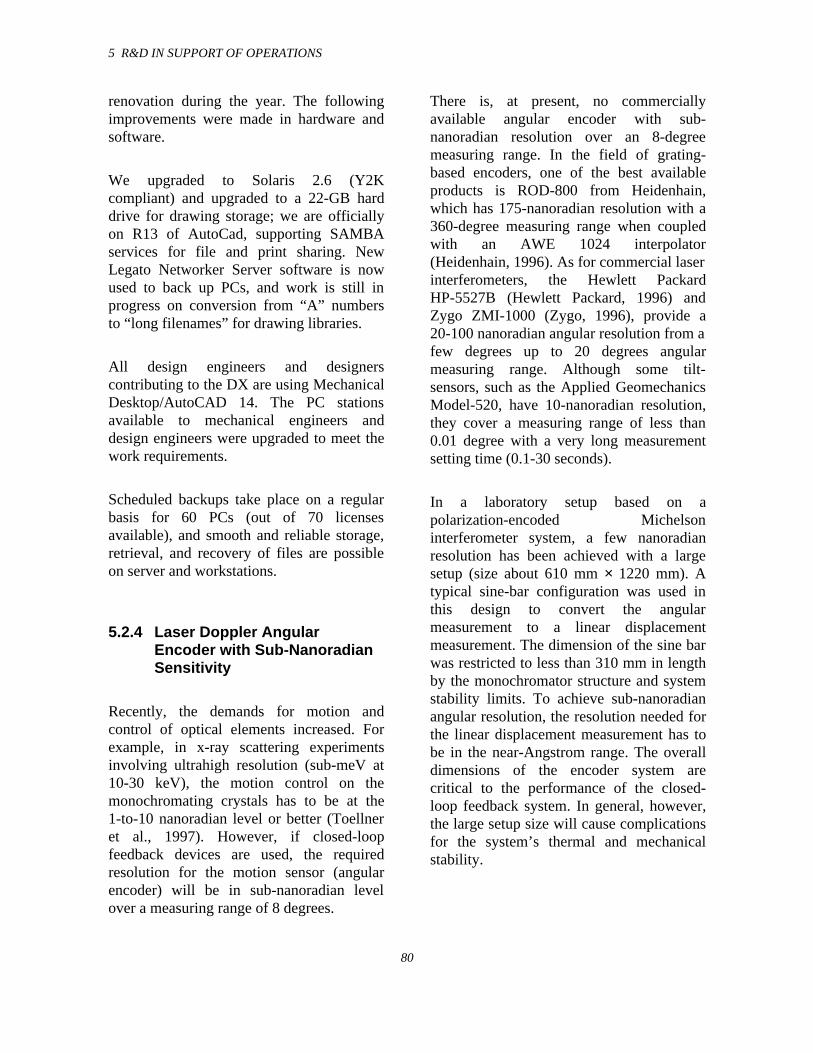
5 R&D IN SUPPORT OF OPERATIONS
80
renovation during the year. The followingimprovements were made in hardware andsoftware.
We upgraded to Solaris 2.6 (Y2Kcompliant) and upgraded to a 22-GB harddrive for drawing storage; we are officiallyon R13 of AutoCad, supporting SAMBAservices for file and print sharing. NewLegato Networker Server software is nowused to back up PCs, and work is still inprogress on conversion from “A” numbersto “long filenames” for drawing libraries.
All design engineers and designerscontributing to the DX are using MechanicalDesktop/AutoCAD 14. The PC stationsavailable to mechanical engineers anddesign engineers were upgraded to meet thework requirements.
Scheduled backups take place on a regularbasis for 60 PCs (out of 70 licensesavailable), and smooth and reliable storage,retrieval, and recovery of files are possibleon server and workstations.
5.2.4 Laser Doppler AngularEncoder with Sub-NanoradianSensitivity
Recently, the demands for motion andcontrol of optical elements increased. Forexample, in x-ray scattering experimentsinvolving ultrahigh resolution (sub-meV at10-30 keV), the motion control on themonochromating crystals has to be at the1-to-10 nanoradian level or better (Toellneret al., 1997). However, if closed-loopfeedback devices are used, the requiredresolution for the motion sensor (angularencoder) will be in sub-nanoradian levelover a measuring range of 8 degrees.
There is, at present, no commerciallyavailable angular encoder with sub-nanoradian resolution over an 8-degreemeasuring range. In the field of grating-based encoders, one of the best availableproducts is ROD-800 from Heidenhain,which has 175-nanoradian resolution with a360-degree measuring range when coupledwith an AWE 1024 interpolator(Heidenhain, 1996). As for commercial laserinterferometers, the Hewlett PackardHP-5527B (Hewlett Packard, 1996) andZygo ZMI-1000 (Zygo, 1996), provide a20-100 nanoradian angular resolution from afew degrees up to 20 degrees angularmeasuring range. Although some tilt-sensors, such as the Applied GeomechanicsModel-520, have 10-nanoradian resolution,they cover a measuring range of less than0.01 degree with a very long measurementsetting time (0.1-30 seconds).
In a laboratory setup based on apolarization-encoded Michelsoninterferometer system, a few nanoradianresolution has been achieved with a largesetup (size about 610 mm × 1220 mm). Atypical sine-bar configuration was used inthis design to convert the angularmeasurement to a linear displacementmeasurement. The dimension of the sine barwas restricted to less than 310 mm in lengthby the monochromator structure and systemstability limits. To achieve sub-nanoradianangular resolution, the resolution needed forthe linear displacement measurement has tobe in the near-Angstrom range. The overalldimensions of the encoder system arecritical to the performance of the closed-loop feedback system. In general, however,the large setup size will cause complicationsfor the system’s thermal and mechanicalstability.
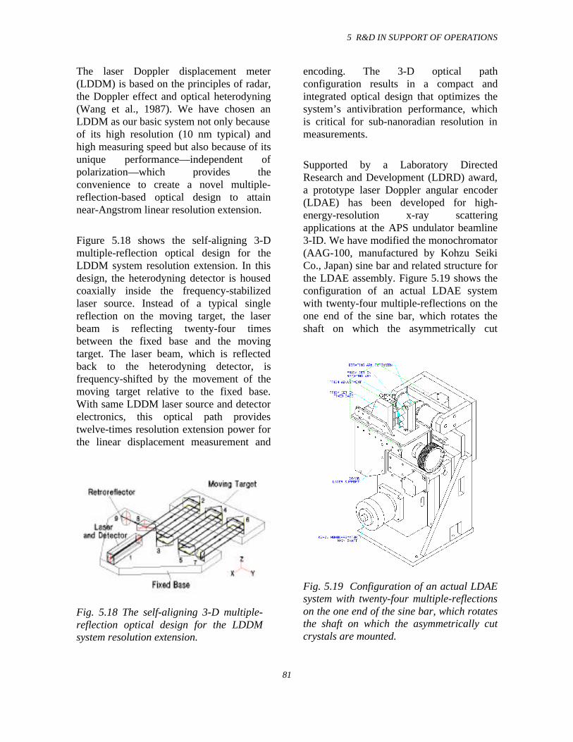
5 R&D IN SUPPORT OF OPERATIONS
81
The laser Doppler displacement meter(LDDM) is based on the principles of radar,the Doppler effect and optical heterodyning(Wang et al., 1987). We have chosen anLDDM as our basic system not only becauseof its high resolution (10 nm typical) andhigh measuring speed but also because of itsunique performance—independent ofpolarization—which provides theconvenience to create a novel multiple-reflection-based optical design to attainnear-Angstrom linear resolution extension.
Figure 5.18 shows the self-aligning 3-Dmultiple-reflection optical design for theLDDM system resolution extension. In thisdesign, the heterodyning detector is housedcoaxially inside the frequency-stabilizedlaser source. Instead of a typical singlereflection on the moving target, the laserbeam is reflecting twenty-four timesbetween the fixed base and the movingtarget. The laser beam, which is reflectedback to the heterodyning detector, isfrequency-shifted by the movement of themoving target relative to the fixed base.With same LDDM laser source and detectorelectronics, this optical path providestwelve-times resolution extension power forthe linear displacement measurement and
Fig. 5.18 The self-aligning 3-D multiple-reflection optical design for the LDDMsystem resolution extension.
encoding. The 3-D optical pathconfiguration results in a compact andintegrated optical design that optimizes thesystem’s antivibration performance, whichis critical for sub-nanoradian resolution inmeasurements.
Supported by a Laboratory DirectedResearch and Development (LDRD) award,a prototype laser Doppler angular encoder(LDAE) has been developed for high-energy-resolution x-ray scatteringapplications at the APS undulator beamline3-ID. We have modified the monochromator(AAG-100, manufactured by Kohzu SeikiCo., Japan) sine bar and related structure forthe LDAE assembly. Figure 5.19 shows theconfiguration of an actual LDAE systemwith twenty-four multiple-reflections on theone end of the sine bar, which rotates theshaft on which the asymmetrically cut
Fig. 5.19 Configuration of an actual LDAEsystem with twenty-four multiple-reflectionson the one end of the sine bar, which rotatesthe shaft on which the asymmetrically cutcrystals are mounted.
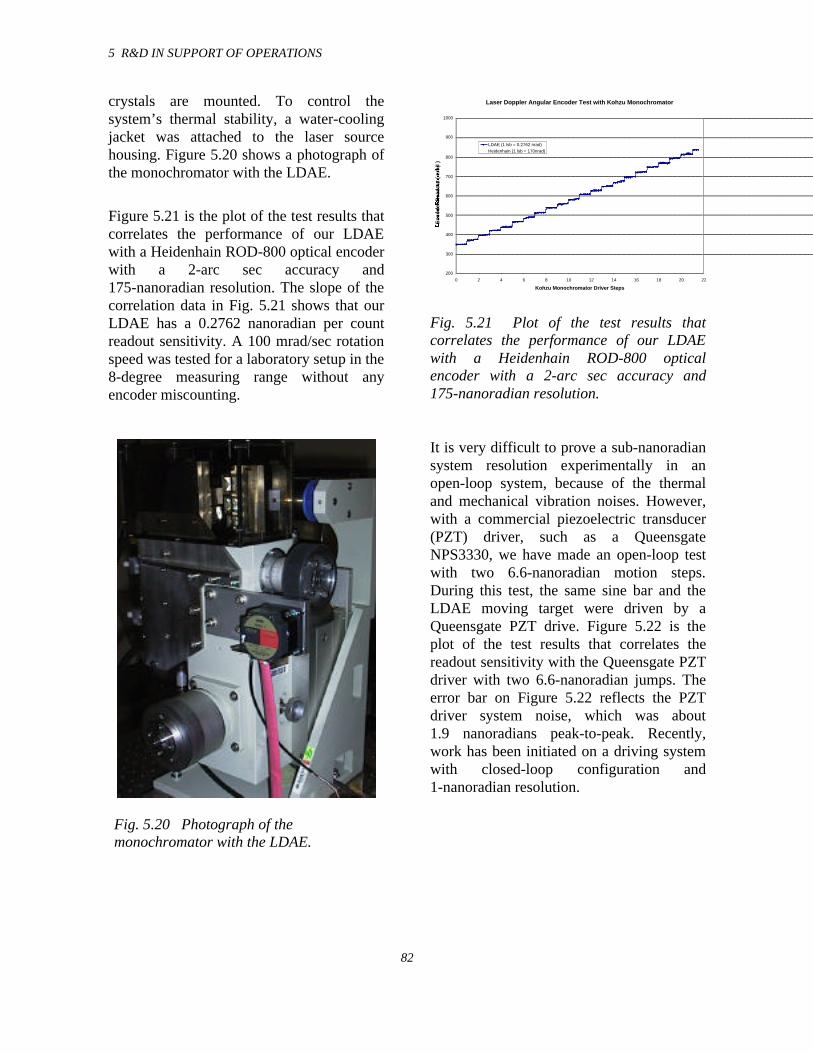
5 R&D IN SUPPORT OF OPERATIONS
82
crystals are mounted. To control thesystem’s thermal stability, a water-coolingjacket was attached to the laser sourcehousing. Figure 5.20 shows a photograph ofthe monochromator with the LDAE.
Figure 5.21 is the plot of the test results thatcorrelates the performance of our LDAEwith a Heidenhain ROD-800 optical encoderwith a 2-arc sec accuracy and175-nanoradian resolution. The slope of thecorrelation data in Fig. 5.21 shows that ourLDAE has a 0.2762 nanoradian per countreadout sensitivity. A 100 mrad/sec rotationspeed was tested for a laboratory setup in the8-degree measuring range without anyencoder miscounting.
Fig. 5.20 Photograph of themonochromator with the LDAE.
Laser Doppler Angular Encoder Test with Kohzu Monochromator
200
300
400
500
600
700
800
900
1000
0 2 4 6 8 10 12 14 16 18 20 22
Kohzu Monochromator Driver Steps
En
co
der
Read
ou
t (
nra
d )
LDAE (1 lsb = 0.2762 nrad)
Heidenhain (1 lsb = 170nrad)
Fig. 5.21 Plot of the test results thatcorrelates the performance of our LDAEwith a Heidenhain ROD-800 opticalencoder with a 2-arc sec accuracy and175-nanoradian resolution.
It is very difficult to prove a sub-nanoradiansystem resolution experimentally in anopen-loop system, because of the thermaland mechanical vibration noises. However,with a commercial piezoelectric transducer(PZT) driver, such as a QueensgateNPS3330, we have made an open-loop testwith two 6.6-nanoradian motion steps.During this test, the same sine bar and theLDAE moving target were driven by aQueensgate PZT drive. Figure 5.22 is theplot of the test results that correlates thereadout sensitivity with the Queensgate PZTdriver with two 6.6-nanoradian jumps. Theerror bar on Figure 5.22 reflects the PZTdriver system noise, which was about1.9 nanoradians peak-to-peak. Recently,work has been initiated on a driving systemwith closed-loop configuration and1-nanoradian resolution.
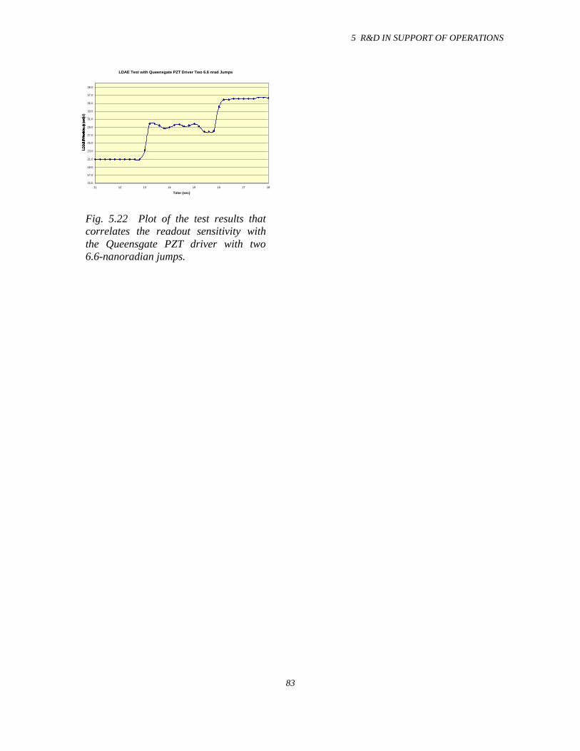
5 R&D IN SUPPORT OF OPERATIONS
83
LDAE Test with Queensgate PZT Driver Two 6.6 nrad Jumps
15.0
17.0
19.0
21.0
23.0
25.0
27.0
29.0
31.0
33.0
35.0
37.0
39.0
11 12 13 14 15 16 17 18
Time (sec)
LD
AE
Read
ou
t (n
rad
)
Fig. 5.22 Plot of the test results thatcorrelates the readout sensitivity withthe Queensgate PZT driver with two6.6-nanoradian jumps.
5 R&D IN SUPPORT OF OPERATIONS
83
5.3 X-ray Optics Development
5.3.1 Introduction
During the past years, the focus of the staffworking on x-ray optics was almostexclusively on the development of high-heat-load monochromators and mirrors andtheir associated hardware. That work haspaid off in the successful development ofcryogenically cooled optical systems(crystals and liquid nitrogen pumps), water-cooled diamond monochromators, andcontact-cooled mirrors with post-mirror,water-cooled monochromators. Many of theother CATs at the APS currently usecryogenically cooled siliconmonochromators and a liquid nitrogen (LN2)pumping system, specified by XFD staff andfirst tested at the APS on the 1-ID beamlineof SRI-CAT. To date, the cryogenicmonochromators and pumps have performedvery well with minimal lost beam time dueto inadequate operation of the cryosystem. Afew of the CATs have opted for a mirror-first geometry utilizing side-cooled silicon
mirrors, also developed by the XFD staff, asthe first optical components in theirbeamlines. These too have performed asdesigned.
We are continuing to improve theperformance of existing optical components,some of those programs are described indetail below, while simultaneously lookingahead to components capable of operationunder even higher powers and powerdensities from enhanced storage ringperformance, such as higher current andsmaller vacuum chamber gaps, and/or5-meter insertion devices. Although thisstudy into higher power optical componentsis not yet complete, some of the initialresults of that study have been included inthis report.
Albeit the design and testing of high-heat-load optical components continue to occupya good part of the time, some staff time hasbeen allocated to x-ray optics developmentsnot directly related to high-heat-load opticalsystems. Sagittally focusing crystals, x-rayinterferometers, compound refractive lens,and use of gradient d-spacing crystals arebut a few of the projects that are currentlyunder development in XFD.
It should be pointed out that an importantside benefit or spin-off of the high-heat-loadmonochromator development program wasthe establishment at the start of the programof a high-quality facility for the fabricationand characterization of single-crystal opticalcomponents. This facility continues tofabricate single-crystal optical componentsfor high-heat-load optics development byXFD staff in addition to providing itsservices to all CATs at the APS. (Seechapter 4 for more details on the capabilitiesand accomplishments of the x-ray opticsfabrication and metrology laboratory.)
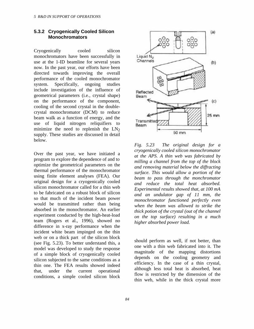
5 R&D IN SUPPORT OF OPERATIONS
84
5.3.2 Cryogenically Cooled SiliconMonochromators
Cryogenically cooled siliconmonochromators have been successfully inuse at the 1-ID beamline for several yearsnow. In the past year, our efforts have beendirected towards improving the overallperformance of the cooled monochromatorsystem. Specifically, ongoing studiesinclude investigation of the influence ofgeometrical parameters (i.e., crystal shape)on the performance of the component,cooling of the second crystal in the double-crystal monochromator (DCM) to reducebeam walk as a function of energy, and theuse of liquid nitrogen reliquifiers tominimize the need to replenish the LN2supply. These studies are discussed in detailbelow.
Over the past year, we have initiated aprogram to explore the dependence of and tooptimize the geometrical parameters on thethermal performance of the monochromatorusing finite element analyses (FEA). Ouroriginal design for a cryogenically cooledsilicon monochromator called for a thin webto be fabricated on a robust block of siliconso that much of the incident beam powerwould be transmitted rather than beingabsorbed in the monochromator. An earlierexperiment conducted by the high-heat-loadteam (Rogers et al., 1996), showed nodifference in x-ray performance when theincident white beam impinged on the thinweb or on a thick part of the silicon block(see Fig. 5.23). To better understand this, amodel was developed to study the responseof a simple block of cryogenically cooledsilicon subjected to the same conditions as athin one. The FEA results showed indeedthat, under the current operationalconditions, a simple cooled silicon block
Fig. 5.23 The original design for acryogenically cooled silicon monochromatorat the APS. A thin web was fabricated bymilling a channel from the top of the blockand removing material below the diffractingsurface. This would allow a portion of thebeam to pass through the monchromatorand reduce the total heat absorbed.Experimental results showed that, at 100 mAand an undulator gap of 11 mm, themonochromator functioned perfectly evenwhen the beam was allowed to strike thethick potion of the crystal (out of the channelon the top surface) resulting in a muchhigher absorbed power load.
should perform as well, if not better, thanone with a thin web fabricated into it. Themagnitude of the mapping distortionsdepends on the cooling geometry andefficiency. In the case of a thin crystal,although less total heat is absorbed, heatflow is restricted by the dimension of thethin web, while in the thick crystal more
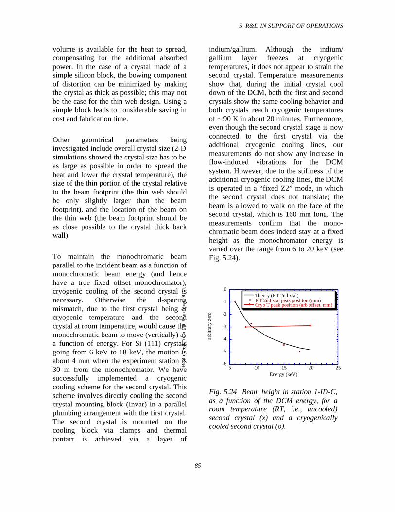
5 R&D IN SUPPORT OF OPERATIONS
85
volume is available for the heat to spread,compensating for the additional absorbedpower. In the case of a crystal made of asimple silicon block, the bowing componentof distortion can be minimized by makingthe crystal as thick as possible; this may notbe the case for the thin web design. Using asimple block leads to considerable saving incost and fabrication time.
Other geomtrical parameters beinginvestigated include overall crystal size (2-Dsimulations showed the crystal size has to beas large as possible in order to spread theheat and lower the crystal temperature), thesize of the thin portion of the crystal relativeto the beam footprint (the thin web shouldbe only slightly larger than the beamfootprint), and the location of the beam onthe thin web (the beam footprint should beas close possible to the crystal thick backwall).
To maintain the monochromatic beamparallel to the incident beam as a function ofmonochromatic beam energy (and hencehave a true fixed offset monochromator),cryogenic cooling of the second crystal isnecessary. Otherwise the d-spacingmismatch, due to the first crystal being atcryogenic temperature and the secondcrystal at room temperature, would cause themonochromatic beam to move (vertically) asa function of energy. For Si (111) crystalsgoing from 6 keV to 18 keV, the motion isabout 4 mm when the experiment station is30 m from the monochromator. We havesuccessfully implemented a cryogeniccooling scheme for the second crystal. Thisscheme involves directly cooling the secondcrystal mounting block (Invar) in a parallelplumbing arrangement with the first crystal.The second crystal is mounted on thecooling block via clamps and thermalcontact is achieved via a layer of
indium/gallium. Although the indium/gallium layer freezes at cryogenictemperatures, it does not appear to strain thesecond crystal. Temperature measurementsshow that, during the initial crystal cooldown of the DCM, both the first and secondcrystals show the same cooling behavior andboth crystals reach cryogenic temperaturesof ~ 90 K in about 20 minutes. Furthermore,even though the second crystal stage is nowconnected to the first crystal via theadditional cryogenic cooling lines, ourmeasurements do not show any increase inflow-induced vibrations for the DCMsystem. However, due to the stiffness of theadditional cryogenic cooling lines, the DCMis operated in a “fixed Z2” mode, in whichthe second crystal does not translate; thebeam is allowed to walk on the face of thesecond crystal, which is 160 mm long. Themeasurements confirm that the mono-chromatic beam does indeed stay at a fixedheight as the monochromator energy isvaried over the range from 6 to 20 keV (seeFig. 5.24).
-6
-5
-4
-3
-2
-1
0
5 10 15 20 25
Theory (RT 2nd xtal)RT 2nd xtal peak position (mm)Cryo T peak position (arb offset, mm)
Bea
m h
eigh
t (m
m)
at 3
0 m
fro
m D
CM
,
arbi
trar
y ze
ro
Energy (keV)
Fig. 5.24 Beam height in station 1-ID-C,as a function of the DCM energy, for aroom temperature (RT, i.e., uncooled)second crystal (x) and a cryogenicallycooled second crystal (o).
5 R&D IN SUPPORT OF OPERATIONS
86
Although the application of cryogeniccooling has been an overwhelming success,the system does have some overheadassociated with its operations. One of theseoverhead items is replacement of liquidnitrogen that has been lost from the systemdue to boil-off in the heat exchanger and tosystem losses. Depending on the cross-sectional size of the incident white beam andthe setting of the undulator A gap, thecryogenic system requires approximately180 liters of LN2 per day. This 180 litersincludes the system losses (throughinsufficient insulation, for example, and isestimated to be in the 80-100 W range) and,depending on the white-beam slit size andundulator gap, that due to the powerabsorbed by the crystal, which can be inexcess of 500 W. (At the highest power, thesystem requirements can double to 360 litersper day.) Currently there is no distributedLN2 in the experiment hall to provide for theLN2 boil-off. Therefore to minimize theneed to constantly change LN2 supplydewars, we have been testing the use ofreliquifiers to recapture the LN2 boil-off.The reliquifaction system we have at presentconsists of two cold heads, each of which iscapable of extracting 180 W from thegaseous nitrogen. As you can see, unless theundulator is running at a very large gapand/or with small slits, the capacity of thecold heads is not sufficient, and we still needto have a LN2 supply tank to supplement thereliquifiers. However, with the addition ofthe reliquifiers, our need to change/resupplythe LN2 tanks has been considerablyreduced from about one per day to about oneevery 3 or 4 days. Efforts to improve thereliability and efficiency of the cryogenicsystem continues with particular effort onimprovements in the efficiency of thecryopumping system.
5.3.3 Diamond Monochromators
A water-cooled diamond high-heat-loadmonochromator was installed as apermanent component in the sector 3 IDbeamline in May 1997. The monochromatorconsists of two synthetic type 1b diamondplates, 7 mm by 5.5 mm by 0.4 mm in size,oriented along the (111) direction. Recentlya 5-mm (beam aperture) ID vacuumchamber, which allows a minimumundulator magnetic gap of 8.5 mm, wasinstalled in the 3-ID beamline straightsection. In this configuration, the calculatedmaximum power and surface power densityfrom the 2.7-cm-period undulator that areabsorbed by the first crystal are 20% and35% larger, respectively, than for undulatorA with a minimum gap of 11 mm. Duringthe January 1998 run, we tested the thermalperformance of the monochromator underthis enhanced heat load. Figure 5.25 showsthe measured FWHM of the (111) and (333)double-crystal rocking curves as a functionof the energy of the (111) reflection, E(111).The undulator gap was changed so that thefirst harmonic energy corresponded withE(111). The calculated maximum absorbedpower was 46 W at 10 keV (13.5-mm gap),and the calculated maximum absorbedsurface power density was 6.8 W/mm2 at9 keV (12.4-mm gap). The absorbed powerand surface power density decrease as afunction of energy for E > 10 keV. We seeno thermal effects on the measured FWHMas a function of the absorbed power orpower density. One possible explanation forthe increasing deviation from theoreticalvalue of the (111) rocking curve FWHM asa function of energy is near-surfaceimperfections/defects in the crystals becausethe beam footprint on the crystal increases
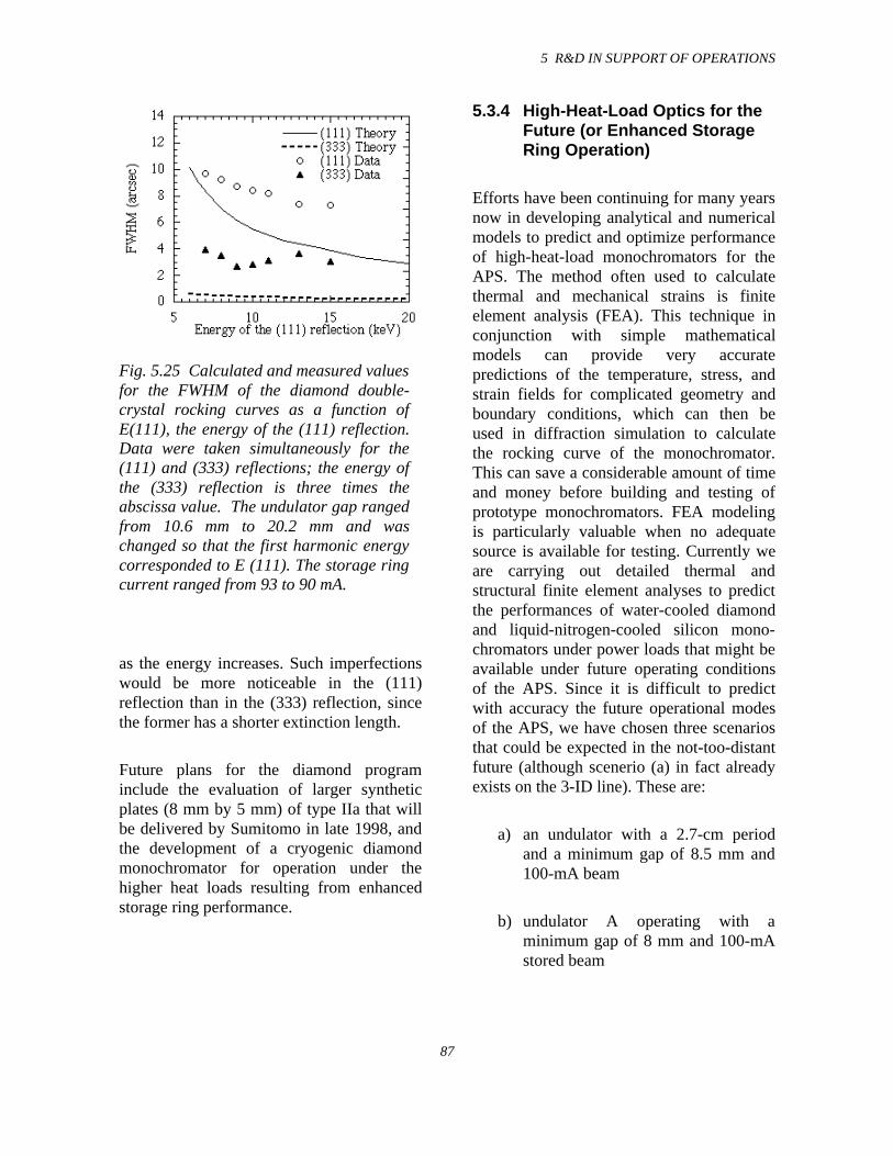
5 R&D IN SUPPORT OF OPERATIONS
87
Fig. 5.25 Calculated and measured valuesfor the FWHM of the diamond double-crystal rocking curves as a function ofE(111), the energy of the (111) reflection.Data were taken simultaneously for the(111) and (333) reflections; the energy ofthe (333) reflection is three times theabscissa value. The undulator gap rangedfrom 10.6 mm to 20.2 mm and waschanged so that the first harmonic energycorresponded to E (111). The storage ringcurrent ranged from 93 to 90 mA.
as the energy increases. Such imperfectionswould be more noticeable in the (111)reflection than in the (333) reflection, sincethe former has a shorter extinction length.
Future plans for the diamond programinclude the evaluation of larger syntheticplates (8 mm by 5 mm) of type IIa that willbe delivered by Sumitomo in late 1998, andthe development of a cryogenic diamondmonochromator for operation under thehigher heat loads resulting from enhancedstorage ring performance.
5.3.4 High-Heat-Load Optics for theFuture (or Enhanced StorageRing Operation)
Efforts have been continuing for many yearsnow in developing analytical and numericalmodels to predict and optimize performanceof high-heat-load monochromators for theAPS. The method often used to calculatethermal and mechanical strains is finiteelement analysis (FEA). This technique inconjunction with simple mathematicalmodels can provide very accuratepredictions of the temperature, stress, andstrain fields for complicated geometry andboundary conditions, which can then beused in diffraction simulation to calculatethe rocking curve of the monochromator.This can save a considerable amount of timeand money before building and testing ofprototype monochromators. FEA modelingis particularly valuable when no adequatesource is available for testing. Currently weare carrying out detailed thermal andstructural finite element analyses to predictthe performances of water-cooled diamondand liquid-nitrogen-cooled silicon mono-chromators under power loads that might beavailable under future operating conditionsof the APS. Since it is difficult to predictwith accuracy the future operational modesof the APS, we have chosen three scenariosthat could be expected in the not-too-distantfuture (although scenerio (a) in fact alreadyexists on the 3-ID line). These are:
a) an undulator with a 2.7-cm periodand a minimum gap of 8.5 mm and100-mA beam
b) undulator A operating with aminimum gap of 8 mm and 100-mAstored beam
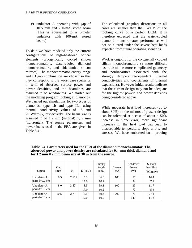
5 R&D IN SUPPORT OF OPERATIONS
88
c) undulator A operating with gap of10.5 mm and 200-mA stored beam(This is equivalent to a 5-meterundulator with 100-mA storedbeam.)
To date we have modeled only the currentconfigurations of high-heat-load opticalelements (cryogenically cooled siliconmonochromtators, water-cooled diamondmonochromators, and side-cooled siliconmirrors). The monochromator energy rangeand ID gap combination are chosen so thatthey correspond to the worst case scenariosin term of absorbed surface power andpower densities, and the beamlines areassumed to be windowless. We started outthe modeling program looking at diamonds.We carried out simulations for two types ofdiamonds: type 1b and type IIa, usingthermal conductivity values of 15 and20 W/cm-K, respectively. The beam size isassumed to be 1.2 mm (vertical) by 2 mm(horizontal). The source parameters andpower loads used in the FEA are given inTable 5.4.
The calculated (angular) distortions in allcases are smaller than the FWHM of therocking curve of a perfect DCM. It istherefore expected that the water-cooleddiamond monchromator performance willnot be altered under the severe heat loadsexpected from future operating scenarios.
Work is ongoing for the crygencially cooledsilicon monochromators (a more difficulttask due to the more complicated geometryand nonlinearities associated with thestrongly temperature-dependent thermalconductivities and coefficients of thermalexpansions). However initial results indicatethat the current design may not be adequatefor the highest powers and power densitiesbeing considered above.
While moderate heat load increases (up toabout 30%) on the mirrors of present designcan be tolerated at a cost of about a 50%increase in slope error, more significantincreases in the heat load can lead tounacceptable temperature, slope errors, andstresses. We have embarked on improving
Table 5.4 Parameters used for the FEA of the diamond monochromator. Theabsorbed power and power density are calculated for 0.4-mm-thick diamond andfor 1.2 mm × 2 mm beam size at 30 m from the source.
SourceGap
(mm) K E (keV)
BraggAngle(deg.)
Current(mA)
AbsorbedPower(W)
Surfaceheat flux
(W/mm2)
Undulator A,period=2.7 cm
8.5 2.181 5.117.0
36.310.2
100 5794
14.47.1
Undulator A,period=3.3 cm
8.0 3.57 3.517.0
59.310.2
100 3372
11.75.4
Undulator A,period=3.3 cm
10.5 2.7 3.517.0
59.310.2
200 73149
27.111.2
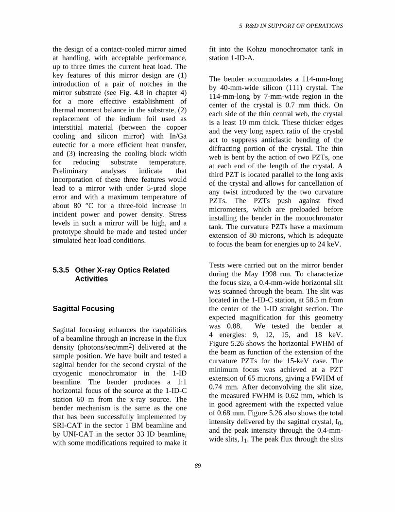
5 R&D IN SUPPORT OF OPERATIONS
89
the design of a contact-cooled mirror aimedat handling, with acceptable performance,up to three times the current heat load. Thekey features of this mirror design are (1)introduction of a pair of notches in themirror substrate (see Fig. 4.8 in chapter 4)for a more effective establishment ofthermal moment balance in the substrate, (2)replacement of the indium foil used asinterstitial material (between the coppercooling and silicon mirror) with In/Gaeutectic for a more efficient heat transfer,and (3) increasing the cooling block widthfor reducing substrate temperature.Preliminary analyses indicate thatincorporation of these three features wouldlead to a mirror with under 5-µrad slopeerror and with a maximum temperature ofabout 80 °C for a three-fold increase inincident power and power density. Stresslevels in such a mirror will be high, and aprototype should be made and tested undersimulated heat-load conditions.
5.3.5 Other X-ray Optics RelatedActivities
Sagittal Focusing
Sagittal focusing enhances the capabilitiesof a beamline through an increase in the fluxdensity (photons/sec/mm2) delivered at thesample position. We have built and tested asagittal bender for the second crystal of thecryogenic monochromator in the 1-IDbeamline. The bender produces a 1:1horizontal focus of the source at the 1-ID-Cstation 60 m from the x-ray source. Thebender mechanism is the same as the onethat has been successfully implemented bySRI-CAT in the sector 1 BM beamline andby UNI-CAT in the sector 33 ID beamline,with some modifications required to make it
fit into the Kohzu monochromator tank instation 1-ID-A.
The bender accommodates a 114-mm-longby 40-mm-wide silicon (111) crystal. The114-mm-long by 7-mm-wide region in thecenter of the crystal is 0.7 mm thick. Oneach side of the thin central web, the crystalis a least 10 mm thick. These thicker edgesand the very long aspect ratio of the crystalact to suppress anticlastic bending of thediffracting portion of the crystal. The thinweb is bent by the action of two PZTs, oneat each end of the length of the crystal. Athird PZT is located parallel to the long axisof the crystal and allows for cancellation ofany twist introduced by the two curvaturePZTs. The PZTs push against fixedmicrometers, which are preloaded beforeinstalling the bender in the monochromatortank. The curvature PZTs have a maximumextension of 80 microns, which is adequateto focus the beam for energies up to 24 keV.
Tests were carried out on the mirror benderduring the May 1998 run. To characterizethe focus size, a 0.4-mm-wide horizontal slitwas scanned through the beam. The slit waslocated in the 1-ID-C station, at 58.5 m fromthe center of the 1-ID straight section. Theexpected magnification for this geometrywas 0.88. We tested the bender at4 energies: 9, 12, 15, and 18 keV.Figure 5.26 shows the horizontal FWHM ofthe beam as function of the extension of thecurvature PZTs for the 15-keV case. Theminimum focus was achieved at a PZTextension of 65 microns, giving a FWHM of0.74 mm. After deconvolving the slit size,the measured FWHM is 0.62 mm, which isin good agreement with the expected valueof 0.68 mm. Figure 5.26 also shows the totalintensity delivered by the sagittal crystal, I0,and the peak intensity through the 0.4-mm-wide slits, I1. The peak flux through the slits
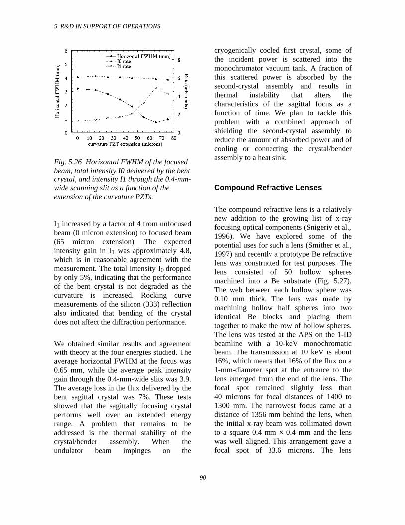
5 R&D IN SUPPORT OF OPERATIONS
90
Fig. 5.26 Horizontal FWHM of the focusedbeam, total intensity I0 delivered by the bentcrystal, and intensity I1 through the 0.4-mm-wide scanning slit as a function of theextension of the curvature PZTs.
I1 increased by a factor of 4 from unfocusedbeam (0 micron extension) to focused beam(65 micron extension). The expectedintensity gain in I1 was approximately 4.8,which is in reasonable agreement with themeasurement. The total intensity I0 droppedby only 5%, indicating that the performanceof the bent crystal is not degraded as thecurvature is increased. Rocking curvemeasurements of the silicon (333) reflectionalso indicated that bending of the crystaldoes not affect the diffraction performance.
We obtained similar results and agreementwith theory at the four energies studied. Theaverage horizontal FWHM at the focus was0.65 mm, while the average peak intensitygain through the 0.4-mm-wide slits was 3.9.The average loss in the flux delivered by thebent sagittal crystal was 7%. These testsshowed that the sagittally focusing crystalperforms well over an extended energyrange. A problem that remains to beaddressed is the thermal stability of thecrystal/bender assembly. When theundulator beam impinges on the
cryogenically cooled first crystal, some ofthe incident power is scattered into themonochromator vacuum tank. A fraction ofthis scattered power is absorbed by thesecond-crystal assembly and results inthermal instability that alters thecharacteristics of the sagittal focus as afunction of time. We plan to tackle thisproblem with a combined approach ofshielding the second-crystal assembly toreduce the amount of absorbed power and ofcooling or connecting the crystal/benderassembly to a heat sink.
Compound Refractive Lenses
The compound refractive lens is a relativelynew addition to the growing list of x-rayfocusing optical components (Snigeriv et al.,1996). We have explored some of thepotential uses for such a lens (Smither et al.,1997) and recently a prototype Be refractivelens was constructed for test purposes. Thelens consisted of 50 hollow spheresmachined into a Be substrate (Fig. 5.27).The web between each hollow sphere was0.10 mm thick. The lens was made bymachining hollow half spheres into twoidentical Be blocks and placing themtogether to make the row of hollow spheres.The lens was tested at the APS on the 1-IDbeamline with a 10-keV monochromaticbeam. The transmission at 10 keV is about16%, which means that 16% of the flux on a1-mm-diameter spot at the entrance to thelens emerged from the end of the lens. Thefocal spot remained slightly less than40 microns for focal distances of 1400 to1300 mm. The narrowest focus came at adistance of 1356 mm behind the lens, whenthe initial x-ray beam was collimated downto a square 0.4 mm × 0.4 mm and the lenswas well aligned. This arrangement gave afocal spot of 33.6 microns. The lens
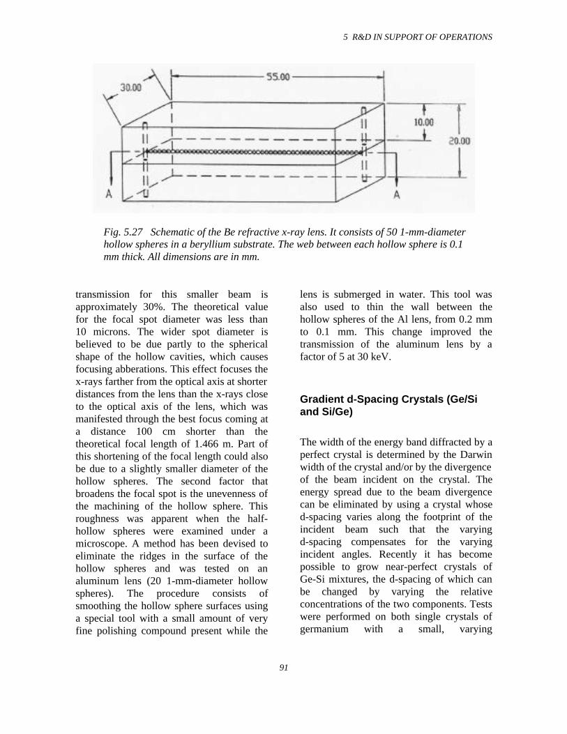
5 R&D IN SUPPORT OF OPERATIONS
91
Fig. 5.27 Schematic of the Be refractive x-ray lens. It consists of 50 1-mm-diameterhollow spheres in a beryllium substrate. The web between each hollow sphere is 0.1mm thick. All dimensions are in mm.
transmission for this smaller beam isapproximately 30%. The theoretical valuefor the focal spot diameter was less than10 microns. The wider spot diameter isbelieved to be due partly to the sphericalshape of the hollow cavities, which causesfocusing abberations. This effect focuses thex-rays farther from the optical axis at shorterdistances from the lens than the x-rays closeto the optical axis of the lens, which wasmanifested through the best focus coming ata distance 100 cm shorter than thetheoretical focal length of 1.466 m. Part ofthis shortening of the focal length could alsobe due to a slightly smaller diameter of thehollow spheres. The second factor thatbroadens the focal spot is the unevenness ofthe machining of the hollow sphere. Thisroughness was apparent when the half-hollow spheres were examined under amicroscope. A method has been devised toeliminate the ridges in the surface of thehollow spheres and was tested on analuminum lens (20 1-mm-diameter hollowspheres). The procedure consists ofsmoothing the hollow sphere surfaces usinga special tool with a small amount of veryfine polishing compound present while the
lens is submerged in water. This tool wasalso used to thin the wall between thehollow spheres of the Al lens, from 0.2 mmto 0.1 mm. This change improved thetransmission of the aluminum lens by afactor of 5 at 30 keV.
Gradient d-Spacing Crystals (Ge/Siand Si/Ge)
The width of the energy band diffracted by aperfect crystal is determined by the Darwinwidth of the crystal and/or by the divergenceof the beam incident on the crystal. Theenergy spread due to the beam divergencecan be eliminated by using a crystal whosed-spacing varies along the footprint of theincident beam such that the varyingd-spacing compensates for the varyingincident angles. Recently it has becomepossible to grow near-perfect crystals ofGe-Si mixtures, the d-spacing of which canbe changed by varying the relativeconcentrations of the two components. Testswere performed on both single crystals ofgermanium with a small, varying
5 R&D IN SUPPORT OF OPERATIONS
92
concentration of silicon and single crystalsof silicon with a varying concentration ofgermanium grown by Nikolai Abrosimov atthe Institute for Crystal Growth, Berlin.Both rocking curves and d-spacings weremeasured. The concentration of Si in theGe/Si crystals varied from 0.1% to 2.6%,which changed the d-spacing by 0.104%.The rocking curves varied from 5 to 20 arcsec in the low Si region (less than 1% Si)and from 20 to 200 arc sec in the high Siregion (greater than 1% Si). Theconcentration of Ge in the two Si/Gecrystals was 3.0% and 3.9%. The rockingcurves (FWHM) varied from 40 arc sec to50 arc sec in the 3.9% Ge crystal and from60 to 120 arc sec in the 3.0% Si crystal.Thus the rocking curves appear to be moresensitive to the parameters and conditionsused during the growing of these crystalsthan to the concentration of Si. A 4% changein the concentration of Ge will change the d-spacings by 0.16%. This would correspondto 67 arc sec at 10 keV for the [111] planesin silicon. At 30 m, this corresponds to avertical height of 10 mm; thus a change inconcentration of 1% or less will be sufficientfor most synchrotron applications. Crystalswith concentration changes of Ge of 1% orless have been grown with mosaic structurewidths of a few arc sec and, thus, should beuseful in synchrotron experiments.
Crystal Lenses for Medical Imaging
A short focal length crystal diffraction lenshas been developed for medical imagingapplications. The lens is designed to focusthe 141-keV gamma ray from 99mTc, whichis injected into the blood stream of cancerpatients. Fast growing cancer cells willincorporate more of the radioactivity thannormal cells. A full body scan is then madeto locate possible cancer sites in the body.
The new medical lens will be used to verifythe presence of these enhanced sites andobtain a 3-D image of the cancer. This 3Dimage will greatly simplify the taking oftissue samples and help guide subsequentsurgery. The lens system will also be able toreject those borderline indications in the fullbody scan that are false and eliminateunnecessary tissue sampling. The lens isconstructed of small copper crystals 4 mmby 4 mm on a side and 2 to 3 mm thick,mounted in rings such that each ring uses adifferent set of crystalline planes to diffractand focus the gamma rays. The focal lengthof this lens for the 141-keV 99mTc line is 50cm. The patient will be located 100 cm (twofocal lengths) from the lens, and the detectorwill be located 100 cm behind the lens.Scanning on and off the cancer site will bedone by moving the patient.
Crystal Lenses for AstrophysicalApplications
An international collaboration (U.S., France,England, Italy, and Germany) has beenformed to perform a series of astrophysicsballoon experiments that use a crystaldiffraction lens to look at gamma rays fromdistant super nova remnants and otherdistant astrophysics sources. The lens willuse Ge and Ge/Si crystals and will beconstructed at the CESR laboratory inToulouse, France. Argonne has supplied theTi-Al alloy lens frame and support structure,as well as the design and technology neededto mount and align the lens crystals.Argonne will also be supporting this effortby making measurement of the diffractionefficiency of different mosaic crystals.Measurements have been made on crystalsof Ge, Ge/Si, and Cu. The first samples ofMo and W crystals are expected in Nov.1998.
5 R&D IN SUPPORT OF OPERATIONS
93
5.4 New Instruments andTechniques
5.4.1 Introduction
The development of beamlineinstrumentation and techniques thatdemonstrate and enhance the uniqueopportunities that are available at theAdvanced Photon Source is undertakenprimarily by XFD scientists and engineersworking on the Synchrotron RadiationInstrumentation Collaborative Access Team(SRI-CAT) beamlines. As the facility hasmatured, the role of SRI-CAT has alsoevolved as reflected in our recently updatedmission statement:
• To conduct R&D activities towardsthe improvement of IDs, standardcomponents, high-heat-load optics,and other novel x-ray opticalcomponents and to developinnovative techniques useful to theentire community of APS CATs.
• To develop and implement strategicinstrumentation programs that willopen up new areas of research at theAPS.
• To attract, educate, and foster newresearch communities in the uses forand applications of synchrotronradiation.
Testing of beamline components and x-rayoptics and the development of novelexperimental techniques primarily take placeon those SRI-CAT beamlines that weredesigned with flexibility in mind. Thebeamlines designed to carry out specific
areas of technique development, calledstrategic instruments, have seen an increasein user demand as they have proceeded fromthe commissioning to the operational phaseover the last year. Construction has begunon sector 4, for another strategicinstrumentation program, namely thegeneration and use of variably polarized x-rays over the energy range of 0.5 to 100keV. The sector 4-ID beamline will jointhose of sectors 2 and 3 to make up thecomplete set of the SRI-CAT strategicinstrumentation programs:
• a milli-electron volt resolutioninstrument
• a micro-to-nano-electron voltinstrument to perform nuclearresonant scattering experiments
• a 1-4 keV radiation source andinstrumentation for use of coherentsoft x-rays
• instrumentation for development ofhard x-ray microfocusing optics andtechniques
• a 0.5 keV to 100 keV variablepolarization beamline
A schematic of the locations of theseprograms, along with the other majorprograms on the SRI-CAT beamlines, isshown in Fig. 5.28. Also indicated inFig. 5.28 is a backscattering beamline (seesection 5.2.3 for details). Because of thelocation of the 1-ID straight section withrespect to other beamlines (i.e., there are noother beamlines immediately upstream), thisbeamline affords a unique opportunity forthe development of a backscattering
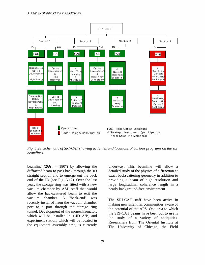
5 R&D IN SUPPORT OF OPERATIONS
94
SRI CATSRI CAT
Sector 1 Sector 2
FOE FOE FOE FOE
Diagnostics,Optics
Development &
High Energy
Optics Development
&Time
Resolved
OpticsDevelopment
&Hard X-rayLithography
#0.5-4 keVCoherentImaging
#Hard X-rayImaging
& Microfocus
FOE - First Optics Enclosure# Strategic Instrument (participation form Scientific Members)
ID ID
Sector 3
FOE
#Inelastic X-ray
Scattering
#Nuclear
ResonantScattering
IDBM BM
Operational
Under Design/Construction
Diagnostics,Optics
Development &
High Energy
#0.5-4 keVVariable
PolarizationTechniques
#Hard X-rayPolarizationOptics &
Techniques
Sector 4
FOE
ID
OpticsDevelopment
andTesting
Back-scatteringBeamline
Fig. 5.28 Schematic of SRI-CAT showing activities and locations of various programs on the sixbeamlines.
beamline (2ΘB = 180°) by allowing thediffracted beam to pass back through the IDstraight section and to emerge out the backend of the ID (see Fig. 5.12). Over the lastyear, the storage ring was fitted with a newvacuum chamber by ASD staff that wouldallow the backscattered beam to exit thevacuum chamber. A "back-end" wasrecently installed from the vacuum chamberport to a port through the storage ringtunnel. Development of the monochromator,which will be installed in 1-ID A/B, andexperiment station, which will be located inthe equipment assembly area, is currently
underway. This beamline will allow adetailed study of the physics of diffraction atexact backscattering geometry in addition toproviding a beam of high resolution andlarge longitudinal coherence length in anearly background-free environment.
The SRI-CAT staff have been active inmaking new scientific communities aware ofthe potential of the APS. One area to whichthe SRI-CAT beams have been put to use isthe study of a variety of antiquities.Researchers from The Oriental Institute atThe University of Chicago, the Field
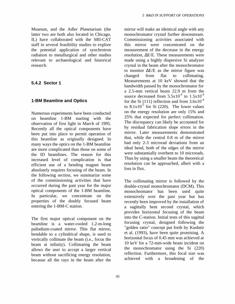
5 R&D IN SUPPORT OF OPERATIONS
95
Museum, and the Adler Planetarium (thelatter two are both also located in Chicago,IL) have collaborated with the SRI-CATstaff in several feasibility studies to explorethe potential application of synchrotronradiation to metallurgical and other studiesrelevant to archaeological and historicalresearch.
5.4.2 Sector 1
1-BM Beamline and Optics
Numerous experiments have been conductedon beamline 1-BM starting with theobservation of first light in March of 1995.Recently all the optical components havebeen put into place to permit operation ofthis beamline as originally designed. Inmany ways the optics on the 1-BM beamlineare more complicated than those on some ofthe ID beamlines. The reason for thisincreased level of complication is thatefficient use of a bending magnet beamabsolutely requires focusing of the beam. Inthe following section, we summarize someof the commissioning activities that haveoccurred during the past year for the majoroptical components of the 1-BM beamline.In particular, we concentrate on theproperties of the doubly focused beamentering the 1-BM-C station.
The first major optical component on thebeamline is a water-cooled 1.2-m-longpalladium-coated mirror. This flat mirror,bendable to a cylindrical shape, is used tovertically collimate the beam (i.e., focus thebeam at infinity). Collimating the beamallows the user to accept a larger verticalbeam without sacrificing energy resolution,because all the rays in the beam after the
mirror will make an identical angle with anymonochromator crystal further downstream.Commissioning activities associated withthis mirror were concentrated on themeasurement of the decrease in the energyresolution, ∆E/E. These measurements weremade using a highly dispersive Si analyzercrystal in the beam after the monochromatorto monitor ∆E/E as the mirror figure waschanged from flat to collimating.Measurements at 10 keV showed that thebandwidth passed by the monochromator fora 2.5-mm vertical beam 22.9 m from thesource decreased from 5.5x10⁻⁴ to 1.5x10⁻⁴
for the Si (111) reflection and from 3.6x10⁻⁴
to 8.1x10⁻⁵ for Si (220). The lower valueson the energy resolution are only 15% and25% that expected for perfect collimation.The discrepancy can likely be accounted forby residual fabrication slope errors in themirror. Later measurements demonstratedthat, while the central 0.8 m of the mirrorhad only 2-3 microrad deviations from anideal bend, both of the edges of the mirrorwere substantially overbent to 10 microrads.Thus by using a smaller beam the theoreticalresolution can be approached, albeit with aloss in flux.
The collimating mirror is followed by thedouble-crystal monochromator (DCM). Thismonochromator has been used quiteextensively over the past year but hasrecently been improved by the installation ofa sagittally bent second crystal, whichprovides horizontal focusing of the beaminto the C-station. Initial tests of this sagittalfocusing crystal, designed following the"golden ratio" concept put forth by Kushniret al. (1993), have been quite promising. Ahorizontal focus of 0.45 mm was achieved at10 keV for a 72-mm-wide beam incident onthe monochromator using the Si (220)reflection. Furthermore, this focal size wasachieved with a broadening of the
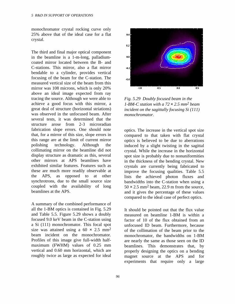
5 R&D IN SUPPORT OF OPERATIONS
96
monochromator crystal rocking curve only25% above that of the ideal case for a flatcrystal.
The third and final major optical componentin the beamline is a 1-m-long, palladium-coated mirror located between the B- andC-stations. This mirror, also a flat mirrorbendable to a cylinder, provides verticalfocusing of the beam for the C-station. Themeasured vertical size of the beam from thismirror was 108 microns, which is only 20%above an ideal image expected from raytracing the source. Although we were able toachieve a good focus with this mirror, agreat deal of structure (horizontal striations)was observed in the unfocused beam. Afterseveral tests, it was determined that thestructure arose from 2-3 microradianfabrication slope errors. One should notethat, for a mirror of this size, slope errors inthis range are at the limit of current mirrorpolishing technology. Although thecollimating mirror on the beamline did notdisplay structure as dramatic as this, severalother mirrors at APS beamlines haveexhibited similar features. Features such asthese are much more readily observable atthe APS, as opposed to at othersynchrotrons, due to the small source sizecoupled with the availability of longbeamlines at the APS.
A summary of the combined performance ofall the 1-BM optics is contained in Fig. 5.29and Table 5.5. Figure 5.29 shows a doublyfocused 9.0 keV beam in the C-station usinga Si (111) monochromator. This focal spotsize was attained using a 60 × 2.5 mm2
beam incident on the monochromator.Profiles of this image give full-width half-maximum (FWHM) values of 0.25 mmvertical and 0.60 mm horizontal, which areroughly twice as large as expected for ideal
Fig. 5.29 Doubly focused beam in the1-BM-C station with a 72 × 2.5 mm2 beamincident on the sagittally focusing Si (111)monochromator.
optics. The increase in the vertical spot sizecompared to that taken with flat crystaloptics is believed to be due to aberrationsinduced by a slight twisting in the sagittalcrystal. While the increase in the horizontalspot size is probably due to nonuniformitiesin the thickness of the bending crystal. Newcrystals are currently being fabricated toimprove the focusing qualities. Table 5.5lists the achieved photon fluxes andbandwidths into the C-station when using a50 × 2.5 mm2 beam, 22.9 m from the source,and it gives the percentage of these valuescompared to the ideal case of perfect optics.
It should be pointed out that the flux valuemeasured on beamline 1-BM is within afactor of 10 of the flux obtained from anunfocused ID beam. Furthermore, becauseof the collimation of the beam prior to themonochromator, the bandwidths on 1-BMare nearly the same as those seen on the IDbeamlines. This demonstrates that, byproperly designing the optics on a bendingmagnet source at the APS and forexperiments that require only a large
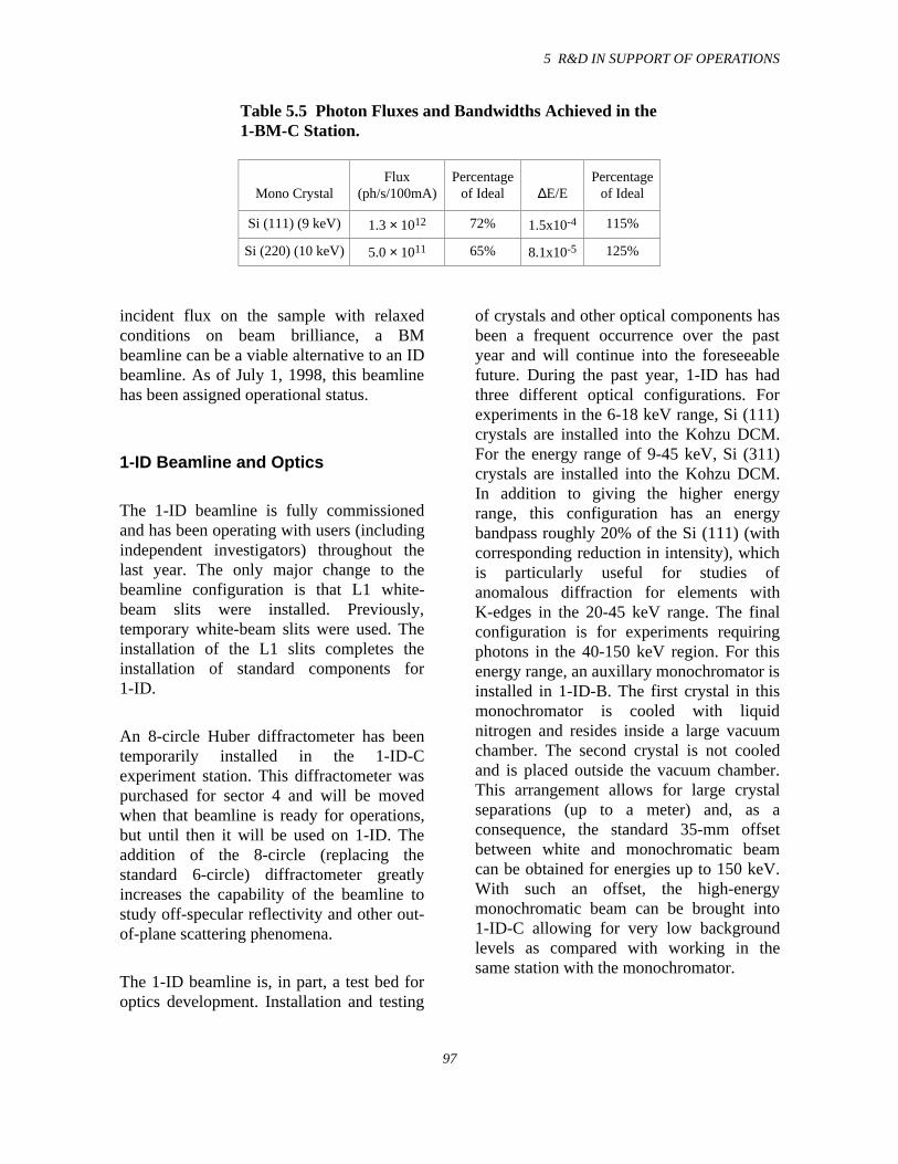
5 R&D IN SUPPORT OF OPERATIONS
97
Table 5.5 Photon Fluxes and Bandwidths Achieved in the1-BM-C Station.
Mono CrystalFlux
(ph/s/100mA)Percentage
of Ideal ∆E/EPercentage
of Ideal
Si (111) (9 keV) 1.3 × 10¹² 72% 1.5x10⁻⁴ 115%
Si (220) (10 keV) 5.0 × 10¹¹ 65% 8.1x10⁻⁵ 125%
incident flux on the sample with relaxedconditions on beam brilliance, a BMbeamline can be a viable alternative to an IDbeamline. As of July 1, 1998, this beamlinehas been assigned operational status.
1-ID Beamline and Optics
The 1-ID beamline is fully commissionedand has been operating with users (includingindependent investigators) throughout thelast year. The only major change to thebeamline configuration is that L1 white-beam slits were installed. Previously,temporary white-beam slits were used. Theinstallation of the L1 slits completes theinstallation of standard components for1-ID.
An 8-circle Huber diffractometer has beentemporarily installed in the 1-ID-Cexperiment station. This diffractometer waspurchased for sector 4 and will be movedwhen that beamline is ready for operations,but until then it will be used on 1-ID. Theaddition of the 8-circle (replacing thestandard 6-circle) diffractometer greatlyincreases the capability of the beamline tostudy off-specular reflectivity and other out-of-plane scattering phenomena.
The 1-ID beamline is, in part, a test bed foroptics development. Installation and testing
of crystals and other optical components hasbeen a frequent occurrence over the pastyear and will continue into the foreseeablefuture. During the past year, 1-ID has hadthree different optical configurations. Forexperiments in the 6-18 keV range, Si (111)crystals are installed into the Kohzu DCM.For the energy range of 9-45 keV, Si (311)crystals are installed into the Kohzu DCM.In addition to giving the higher energyrange, this configuration has an energybandpass roughly 20% of the Si (111) (withcorresponding reduction in intensity), whichis particularly useful for studies ofanomalous diffraction for elements withK-edges in the 20-45 keV range. The finalconfiguration is for experiments requiringphotons in the 40-150 keV region. For thisenergy range, an auxillary monochromator isinstalled in 1-ID-B. The first crystal in thismonochromator is cooled with liquidnitrogen and resides inside a large vacuumchamber. The second crystal is not cooledand is placed outside the vacuum chamber.This arrangement allows for large crystalseparations (up to a meter) and, as aconsequence, the standard 35-mm offsetbetween white and monochromatic beamcan be obtained for energies up to 150 keV.With such an offset, the high-energymonochromatic beam can be brought into1-ID-C allowing for very low backgroundlevels as compared with working in thesame station with the monochromator.
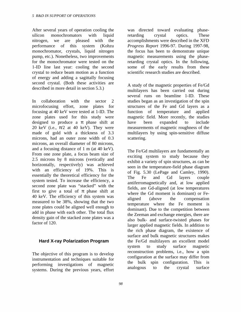
5 R&D IN SUPPORT OF OPERATIONS
98
After several years of operation cooling thesilicon monochromators with liquidnitrogen, we are pleased with theperformance of this system (Kohzumonochromator, crystals, liquid nitrogenpump, etc.). Nonetheless, two improvementsfor the monochromator were tested on the1-ID line last year: cooling the secondcrystal to reduce beam motion as a functionof energy and adding a sagittally focusingsecond crystal. (Both these activities aredescribed in more detail in section 5.3.)
In collaboration with the sector 2microfocusing effort, zone plates forfocusing at 40 keV were tested at 1-ID. Thezone plates used for this study weredesigned to produce a π phase shift at20 keV (i.e., π/2 at 40 keV). They weremade of gold with a thickness of 3.3microns, had an outer zone width of 0.3microns, an overall diameter of 80 microns,and a focusing distance of 1 m (at 40 keV).From one zone plate, a focus beam size of2.5 microns by 8 microns (vertically andhorizontally, respectively) was achievedwith an efficiency of 19%. This isessentially the theoretical efficiency for thesystem tested. To increase the efficiency, asecond zone plate was “stacked” with thefirst to give a total of π phase shift at40 keV. The efficiency of this system wasmeasured to be 38%, showing that the twozone plates could be aligned well enough toadd in phase with each other. The total fluxdensity gain of the stacked zone plates was afactor of 120.
Hard X-ray Polarization Program
The objective of this program is to developinstrumentation and techniques suitable forperforming investigations of magneticsystems. During the previous years, effort
was directed toward evaluating phase-retarding crystal optics. Theseaccomplishments were described in the XFDProgress Report 1996-97. During 1997-98,the focus has been to demonstrate uniquemagnetic measurements using the phase-retarding crystal optics. In the following,some of the early results from thesescientific research studies are described.
A study of the magnetic properties of Fe/Gdmultilayers has been carried out duringseveral runs on beamline 1-ID. Thesestudies began as an investigation of the spinstructures of the Fe and Gd layers as afunction of temperature and appliedmagnetic field. More recently, the studieshave been expanded to includemeasurements of magnetic roughness of themultilayers by using spin-sensitive diffusescattering.
The Fe/Gd multilayers are fundamentally anexciting system to study because theyexhibit a variety of spin structures, as can beseen in the temperature-field phase diagramof Fig. 5.30 (LePage and Camley, 1990).The Fe and Gd layers coupleantiferromagnetically and, at low appliedfields, are Gd-aligned (at low temperatureswhere the Gd moment is dominant) or Fe-aligned (above the compensationtemperature where the Fe moment isdominant). Due to the competition betweenthe Zeeman and exchange energies, there arealso bulk- and surface-twisted phases forlarger applied magnetic fields. In addition tothe rich phase diagram, the existence ofsurface and bulk magnetic structures makesthe Fe/Gd multilayers an excellent modelsystem to study surface magneticreconstruction problems, i.e., how a spinconfiguration at the surface may differ fromthe bulk spin configuration. This isanalogous to the crystal surface
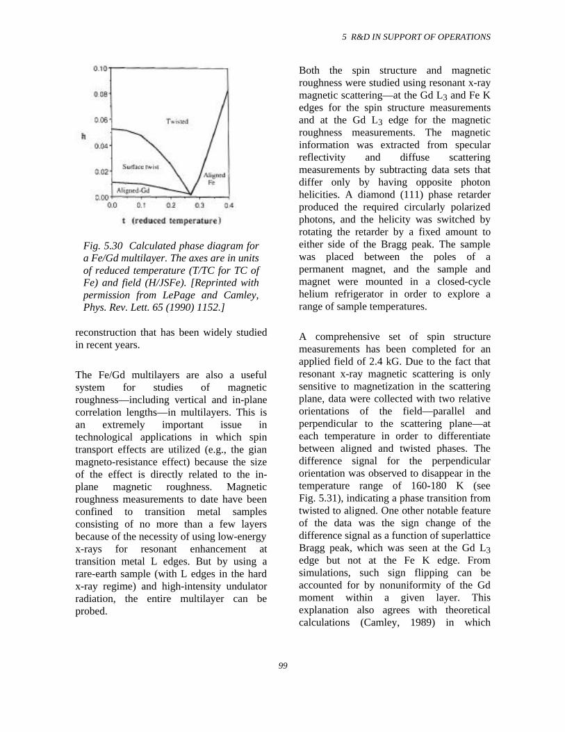
5 R&D IN SUPPORT OF OPERATIONS
99
Fig. 5.30 Calculated phase diagram fora Fe/Gd multilayer. The axes are in unitsof reduced temperature (T/TC for TC ofFe) and field (H/JSFe). [Reprinted withpermission from LePage and Camley,Phys. Rev. Lett. 65 (1990) 1152.]
reconstruction that has been widely studiedin recent years.
The Fe/Gd multilayers are also a usefulsystem for studies of magneticroughness—including vertical and in-planecorrelation lengths—in multilayers. This isan extremely important issue intechnological applications in which spintransport effects are utilized (e.g., the gianmagneto-resistance effect) because the sizeof the effect is directly related to the in-plane magnetic roughness. Magneticroughness measurements to date have beenconfined to transition metal samplesconsisting of no more than a few layersbecause of the necessity of using low-energyx-rays for resonant enhancement attransition metal L edges. But by using arare-earth sample (with L edges in the hardx-ray regime) and high-intensity undulatorradiation, the entire multilayer can beprobed.
Both the spin structure and magneticroughness were studied using resonant x-raymagnetic scattering—at the Gd L3 and Fe Kedges for the spin structure measurementsand at the Gd L3 edge for the magneticroughness measurements. The magneticinformation was extracted from specularreflectivity and diffuse scatteringmeasurements by subtracting data sets thatdiffer only by having opposite photonhelicities. A diamond (111) phase retarderproduced the required circularly polarizedphotons, and the helicity was switched byrotating the retarder by a fixed amount toeither side of the Bragg peak. The samplewas placed between the poles of apermanent magnet, and the sample andmagnet were mounted in a closed-cyclehelium refrigerator in order to explore arange of sample temperatures.
A comprehensive set of spin structuremeasurements has been completed for anapplied field of 2.4 kG. Due to the fact thatresonant x-ray magnetic scattering is onlysensitive to magnetization in the scatteringplane, data were collected with two relativeorientations of the field—parallel andperpendicular to the scattering plane—ateach temperature in order to differentiatebetween aligned and twisted phases. Thedifference signal for the perpendicularorientation was observed to disappear in thetemperature range of 160-180 K (seeFig. 5.31), indicating a phase transition fromtwisted to aligned. One other notable featureof the data was the sign change of thedifference signal as a function of superlatticeBragg peak, which was seen at the Gd L3edge but not at the Fe K edge. Fromsimulations, such sign flipping can beaccounted for by nonuniformity of the Gdmoment within a given layer. Thisexplanation also agrees with theoreticalcalculations (Camley, 1989) in which
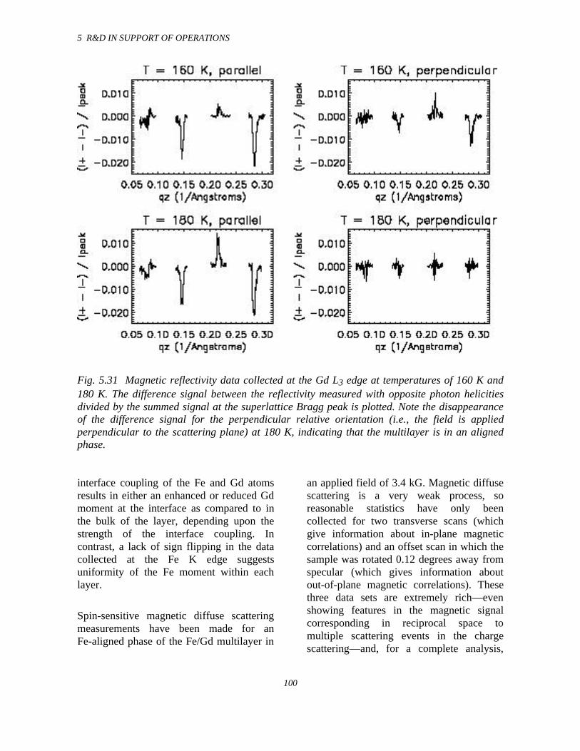
5 R&D IN SUPPORT OF OPERATIONS
100
Fig. 5.31 Magnetic reflectivity data collected at the Gd L3 edge at temperatures of 160 K and180 K. The difference signal between the reflectivity measured with opposite photon helicitiesdivided by the summed signal at the superlattice Bragg peak is plotted. Note the disappearanceof the difference signal for the perpendicular relative orientation (i.e., the field is appliedperpendicular to the scattering plane) at 180 K, indicating that the multilayer is in an alignedphase.
interface coupling of the Fe and Gd atomsresults in either an enhanced or reduced Gdmoment at the interface as compared to inthe bulk of the layer, depending upon thestrength of the interface coupling. Incontrast, a lack of sign flipping in the datacollected at the Fe K edge suggestsuniformity of the Fe moment within eachlayer.
Spin-sensitive magnetic diffuse scatteringmeasurements have been made for anFe-aligned phase of the Fe/Gd multilayer in
an applied field of 3.4 kG. Magnetic diffusescattering is a very weak process, soreasonable statistics have only beencollected for two transverse scans (whichgive information about in-plane magneticcorrelations) and an offset scan in which thesample was rotated 0.12 degrees away fromspecular (which gives information aboutout-of-plane magnetic correlations). Thesethree data sets are extremely rich—evenshowing features in the magnetic signalcorresponding in reciprocal space tomultiple scattering events in the chargescattering—and, for a complete analysis,
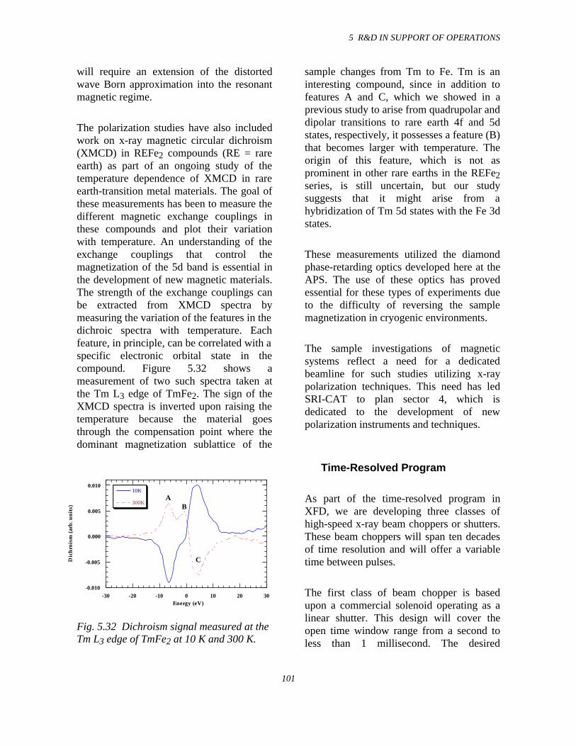
5 R&D IN SUPPORT OF OPERATIONS
101
will require an extension of the distortedwave Born approximation into the resonantmagnetic regime.
The polarization studies have also includedwork on x-ray magnetic circular dichroism(XMCD) in REFe2 compounds (RE = rareearth) as part of an ongoing study of thetemperature dependence of XMCD in rareearth-transition metal materials. The goal ofthese measurements has been to measure thedifferent magnetic exchange couplings inthese compounds and plot their variationwith temperature. An understanding of theexchange couplings that control themagnetization of the 5d band is essential inthe development of new magnetic materials.The strength of the exchange couplings canbe extracted from XMCD spectra bymeasuring the variation of the features in thedichroic spectra with temperature. Eachfeature, in principle, can be correlated with aspecific electronic orbital state in thecompound. Figure 5.32 shows ameasurement of two such spectra taken atthe Tm L3 edge of TmFe2. The sign of theXMCD spectra is inverted upon raising thetemperature because the material goesthrough the compensation point where thedominant magnetization sublattice of the
-0.010
-0.005
0.000
0.005
0.010
-30 -20 -10 0 10 20 30
10K
300K
Dic
hro
ism
(ar
b. u
nit
s)
Energy (eV)
AB
C
Fig. 5.32 Dichroism signal measured at theTm L3 edge of TmFe2 at 10 K and 300 K.
sample changes from Tm to Fe. Tm is aninteresting compound, since in addition tofeatures A and C, which we showed in aprevious study to arise from quadrupolar anddipolar transitions to rare earth 4f and 5dstates, respectively, it possesses a feature (B)that becomes larger with temperature. Theorigin of this feature, which is not asprominent in other rare earths in the REFe2series, is still uncertain, but our studysuggests that it might arise from ahybridization of Tm 5d states with the Fe 3dstates.
These measurements utilized the diamondphase-retarding optics developed here at theAPS. The use of these optics has provedessential for these types of experiments dueto the difficulty of reversing the samplemagnetization in cryogenic environments.
The sample investigations of magneticsystems reflect a need for a dedicatedbeamline for such studies utilizing x-raypolarization techniques. This need has ledSRI-CAT to plan sector 4, which isdedicated to the development of newpolarization instruments and techniques.
Time-Resolved Program
As part of the time-resolved program inXFD, we are developing three classes ofhigh-speed x-ray beam choppers or shutters.These beam choppers will span ten decadesof time resolution and will offer a variabletime between pulses.
The first class of beam chopper is basedupon a commercial solenoid operating as alinear shutter. This design will cover theopen time window range from a second toless than 1 millisecond. The desired
5 R&D IN SUPPORT OF OPERATIONS
102
operating parameters are two fold. First, alinear motion of the solenoid plunger, whichcan open or close an aperture quickly, on theorder of 1 to 2 ms, and remain open orclosed for a period varying from 20 ms to asecond. The maximum operation rate wouldbe 50 Hz. Second, we want a system thatcan open and close the time window on theorder of 300 microseconds and remainclosed for an unspecified time. Both of thesedesigns depend upon the driving powersupply. A pulsed high-voltage (400 V)high-current (5 A) power supply is beingdeveloped in house to drive the solenoidbeam choppers. They will be used with thecharge coupled device (CCD) cameradetectors and high-speed beam chopperdescribed below.
The next class of beam chopper is also basedupon a commercial product, namely a high-speed line scanner. The central componentfor this device is a high-speed (80000 RPM)rotating beryllium cylinder with a narrowslot through the center that can rotatesynchronously with respect to the orbitalfrequency of the storage ring. The largenumerical aperture of the slot forms a fixedopen time window of about2.65 microseconds. (The close time is about300 microseconds, hence the need for thefast solenoid shutter described above forapplications requiring a longer close time.)Pulses shorter than 2.65 microsecondswould require selective loading patterns ofthe APS storage ring, but in general, x-raypulses as short as 75 psec, corresponding toa single bunch of stored particles, could beachieved with this synchronously operatedbeam chopper. Delivery of this item isexpected in the fall of 1998.
The final class of beam chopper consists of arotating Si crystal cube. In the normal fillpattern of the APS storage ring, about two
thirds of the ring is filled, usually with about25 bunches. The time between thesebunches is typically about 100 - 150 ns(depends on the exact fill pattern). Forcertain time-resolved experiments, theability to change this time structure isdesirable. In particular, a longer inter-bunchtime may be useful. With a rotating crystal,we have demonstrated that it is possible toincrease the time between x-ray bursts. Byusing a 15-mm silicon cube mounted on aStanford Research Instruments SR 540 beamchopper motor, we were able to takeadvantage of the small Darwin widthopening angle of the crystal as a fast shutterfor a monochromatic beam. The crystal wascut so that there were four Si (220)reflecting surfaces available. Depending onthe speed of the crystal rotation,monochromatic x-ray bursts with varyinginterburst times from about 1 second to 250msec were achieved. In the first case, thelength of the x-ray burst is actually the entirefill pattern of the synchrotron ring(~ 2.5 µsec); while in the latter case, thelength of the x-ray burst is actually oneindividual pulse (~ 100 ps) from the fillpattern. In this initial demonstration, therotating crystal chopper was operatedasynchronously with the storage ring period(Fig. 5.33). In order to be a more usefulinstrument, the rotating crystal chopper mustbe able to operate synchronously with thestorage ring. We are currently looking intoimprovements of the rotation devices thatwill permit synchronous operations.
The other main area of instrumentationdevelopment ongoing in the time-resolvedprogram involves a high-speed digital CCDcamera. During the last year, the softwarefor operating the camera has been improvedsignificantly. The following aspects havebeen added or enhanced: user friendliness,ability of executing loop commands within
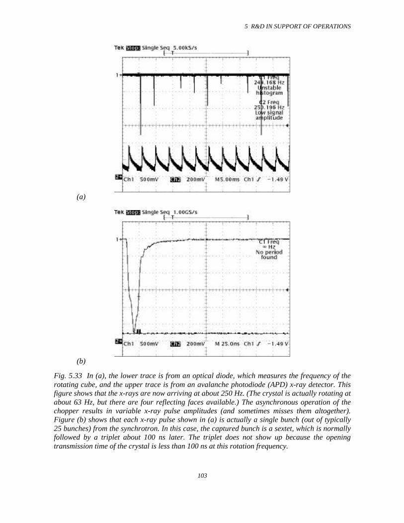
5 R&D IN SUPPORT OF OPERATIONS
103
(a)
(b)
Fig. 5.33 In (a), the lower trace is from an optical diode, which measures the frequency of therotating cube, and the upper trace is from an avalanche photodiode (APD) x-ray detector. Thisfigure shows that the x-rays are now arriving at about 250 Hz. (The crystal is actually rotating atabout 63 Hz, but there are four reflecting faces available.) The asynchronous operation of thechopper results in variable x-ray pulse amplitudes (and sometimes misses them altogether).Figure (b) shows that each x-ray pulse shown in (a) is actually a single bunch (out of typically25 bunches) from the synchrotron. In this case, the captured bunch is a sextet, which is normallyfollowed by a triplet about 100 ns later. The triplet does not show up because the openingtransmission time of the crystal is less than 100 ns at this rotation frequency.
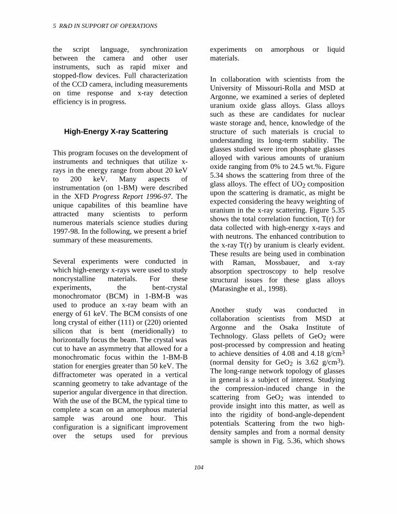
5 R&D IN SUPPORT OF OPERATIONS
104
the script language, synchronizationbetween the camera and other userinstruments, such as rapid mixer andstopped-flow devices. Full characterizationof the CCD camera, including measurementson time response and x-ray detectionefficiency is in progress.
High-Energy X-ray Scattering
This program focuses on the development ofinstruments and techniques that utilize x-rays in the energy range from about 20 keVto 200 keV. Many aspects ofinstrumentation (on 1-BM) were describedin the XFD Progress Report 1996-97. Theunique capabilites of this beamline haveattracted many scientists to performnumerous materials science studies during1997-98. In the following, we present a briefsummary of these measurements.
Several experiments were conducted inwhich high-energy x-rays were used to studynoncrystalline materials. For theseexperiments, the bent-crystalmonochromator (BCM) in 1-BM-B wasused to produce an x-ray beam with anenergy of 61 keV. The BCM consists of onelong crystal of either (111) or (220) orientedsilicon that is bent (meridionally) tohorizontally focus the beam. The crystal wascut to have an asymmetry that allowed for amonochromatic focus within the 1-BM-Bstation for energies greater than 50 keV. Thediffractometer was operated in a verticalscanning geometry to take advantage of thesuperior angular divergence in that direction.With the use of the BCM, the typical time tocomplete a scan on an amorphous materialsample was around one hour. Thisconfiguration is a significant improvementover the setups used for previous
experiments on amorphous or liquidmaterials.
In collaboration with scientists from theUniversity of Missouri-Rolla and MSD atArgonne, we examined a series of depleteduranium oxide glass alloys. Glass alloyssuch as these are candidates for nuclearwaste storage and, hence, knowledge of thestructure of such materials is crucial tounderstanding its long-term stability. Theglasses studied were iron phosphate glassesalloyed with various amounts of uraniumoxide ranging from 0% to 24.5 wt.%. Figure5.34 shows the scattering from three of theglass alloys. The effect of UO2 compositionupon the scattering is dramatic, as might beexpected considering the heavy weighting ofuranium in the x-ray scattering. Figure 5.35shows the total correlation function, T(r) fordata collected with high-energy x-rays andwith neutrons. The enhanced contribution tothe x-ray T(r) by uranium is clearly evident.These results are being used in combinationwith Raman, Mossbauer, and x-rayabsorption spectroscopy to help resolvestructural issues for these glass alloys(Marasinghe et al., 1998).
Another study was conducted incollaboration scientists from MSD atArgonne and the Osaka Institute ofTechnology. Glass pellets of GeO2 werepost-processed by compression and heatingto achieve densities of 4.08 and 4.18 g/cm3
(normal density for GeO2 is 3.62 g/cm3).The long-range network topology of glassesin general is a subject of interest. Studyingthe compression-induced change in thescattering from GeO2 was intended toprovide insight into this matter, as well asinto the rigidity of bond-angle-dependentpotentials. Scattering from the two high-density samples and from a normal densitysample is shown in Fig. 5.36, which shows
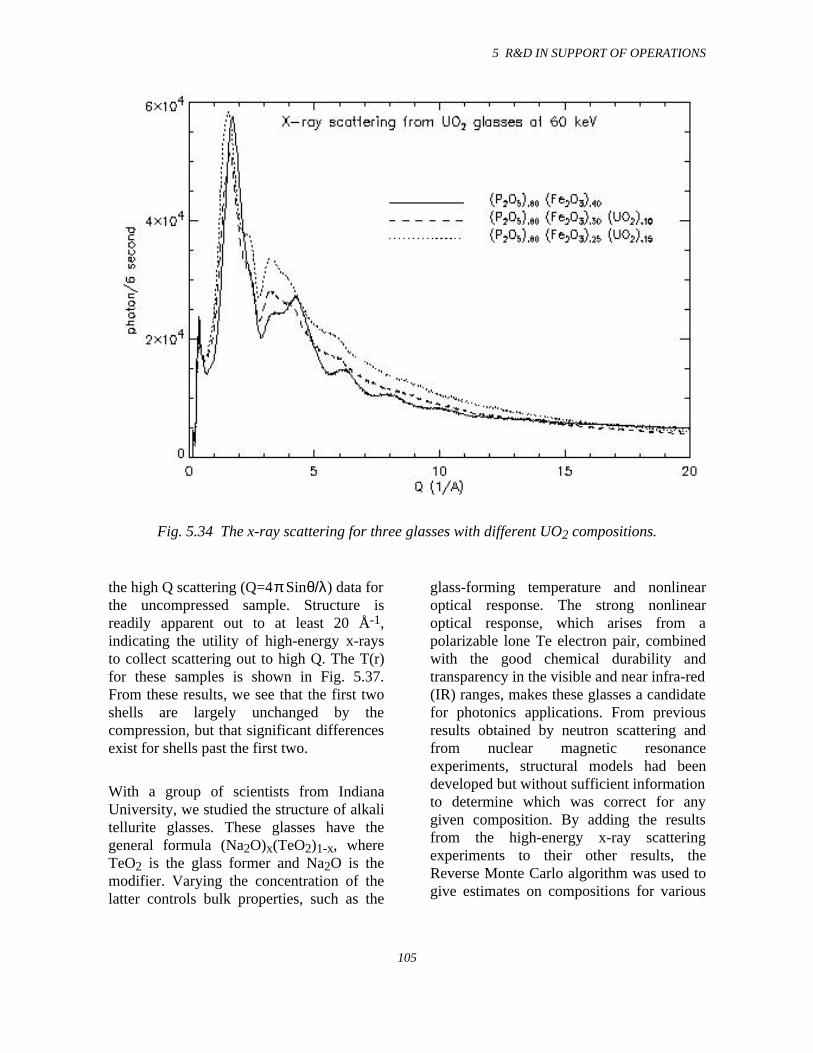
5 R&D IN SUPPORT OF OPERATIONS
105
Fig. 5.34 The x-ray scattering for three glasses with different UO2 compositions.
the high Q scattering (Q=4π Sinθ/λ) data forthe uncompressed sample. Structure isreadily apparent out to at least 20 Å-1,indicating the utility of high-energy x-raysto collect scattering out to high Q. The T(r)for these samples is shown in Fig. 5.37.From these results, we see that the first twoshells are largely unchanged by thecompression, but that significant differencesexist for shells past the first two.
With a group of scientists from IndianaUniversity, we studied the structure of alkalitellurite glasses. These glasses have thegeneral formula (Na2O)x(TeO2)1-x, whereTeO2 is the glass former and Na2O is themodifier. Varying the concentration of thelatter controls bulk properties, such as the
glass-forming temperature and nonlinearoptical response. The strong nonlinearoptical response, which arises from apolarizable lone Te electron pair, combinedwith the good chemical durability andtransparency in the visible and near infra-red(IR) ranges, makes these glasses a candidatefor photonics applications. From previousresults obtained by neutron scattering andfrom nuclear magnetic resonanceexperiments, structural models had beendeveloped but without sufficient informationto determine which was correct for anygiven composition. By adding the resultsfrom the high-energy x-ray scatteringexperiments to their other results, theReverse Monte Carlo algorithm was used togive estimates on compositions for various
5 R&D IN SUPPORT OF OPERATIONS
106
Fig. 5.35 The total correlation function derived from neutron and x-ray scatteringfor three glasses with different UO2 compositions.
structural components (McLaughlin et al.,1998).
The high-energy scattering capabilityprovided at beamline 1-BM is unique, andmany scientists have taken advantage of it tostudy materials science problems requiringx-ray scattering data for full understanding.
5.4.3 Sector 2
2-BM Beamline and Optics
The 2-BM beamline, consisting of a bendingmagnet source and the 2-BM-A and 2-BM-B
experiment stations, has been commissionedand operational since the end of 1997. Thebeamline as a whole has demonstratedexcellent performance. The last majoroptical component to be installed was theM2 mirror in 2-BM-B, a 1.2-m-long Si flat,side-cooled mirror with Si, Rh, and Ptstripes on its reflective surface forbroadband energy selection up to ~35 keV.This mirror and its cousin in 2-BM-A haveperformed very well, demonstratingreflectivity curves that are within 5% of theexpected theoretical reflectivities. The lastremaining optical component to be installedas per the Sector 2 Final Design Report is adouble-multilayer monochromator (DMM)for medium-bandwidth energy selection.
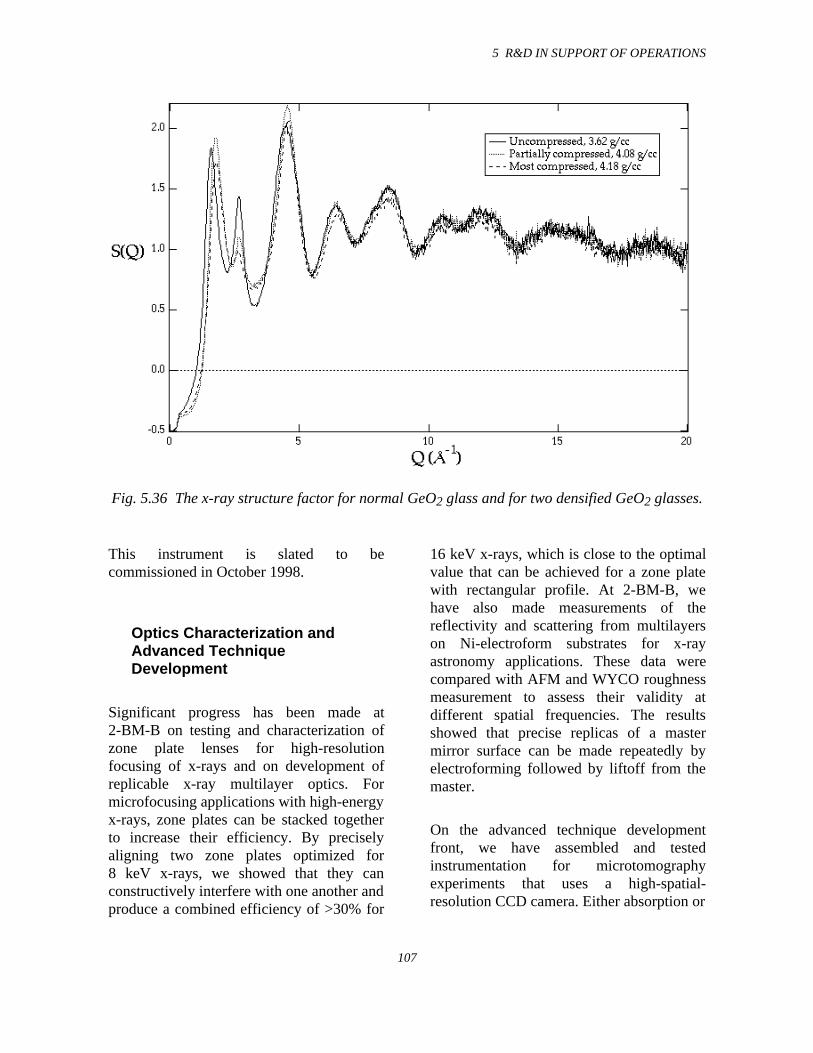
5 R&D IN SUPPORT OF OPERATIONS
107
Fig. 5.36 The x-ray structure factor for normal GeO2 glass and for two densified GeO2 glasses.
This instrument is slated to becommissioned in October 1998.
Optics Characterization andAdvanced TechniqueDevelopment
Significant progress has been made at2-BM-B on testing and characterization ofzone plate lenses for high-resolutionfocusing of x-rays and on development ofreplicable x-ray multilayer optics. Formicrofocusing applications with high-energyx-rays, zone plates can be stacked togetherto increase their efficiency. By preciselyaligning two zone plates optimized for8 keV x-rays, we showed that they canconstructively interfere with one another andproduce a combined efficiency of >30% for
16 keV x-rays, which is close to the optimalvalue that can be achieved for a zone platewith rectangular profile. At 2-BM-B, wehave also made measurements of thereflectivity and scattering from multilayerson Ni-electroform substrates for x-rayastronomy applications. These data werecompared with AFM and WYCO roughnessmeasurement to assess their validity atdifferent spatial frequencies. The resultsshowed that precise replicas of a mastermirror surface can be made repeatedly byelectroforming followed by liftoff from themaster.
On the advanced technique developmentfront, we have assembled and testedinstrumentation for microtomographyexperiments that uses a high-spatial-resolution CCD camera. Either absorption or
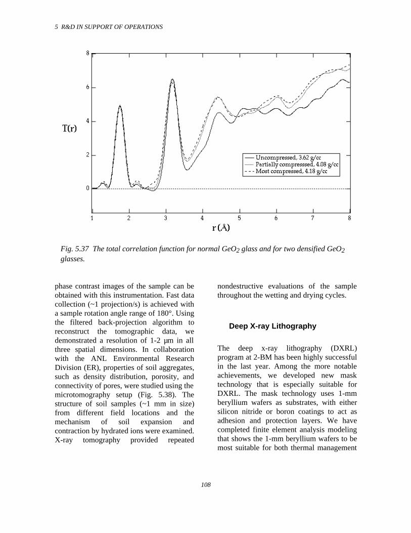
5 R&D IN SUPPORT OF OPERATIONS
108
Fig. 5.37 The total correlation function for normal GeO2 glass and for two densified GeO2glasses.
phase contrast images of the sample can beobtained with this instrumentation. Fast datacollection (~1 projection/s) is achieved witha sample rotation angle range of 180°. Usingthe filtered back-projection algorithm toreconstruct the tomographic data, wedemonstrated a resolution of 1-2 µm in allthree spatial dimensions. In collaborationwith the ANL Environmental ResearchDivision (ER), properties of soil aggregates,such as density distribution, porosity, andconnectivity of pores, were studied using themicrotomography setup (Fig. 5.38). Thestructure of soil samples (~1 mm in size)from different field locations and themechanism of soil expansion andcontraction by hydrated ions were examined.X-ray tomography provided repeated
nondestructive evaluations of the samplethroughout the wetting and drying cycles.
Deep X-ray Lithography
The deep x-ray lithography (DXRL)program at 2-BM has been highly successfulin the last year. Among the more notableachievements, we developed new masktechnology that is especially suitable forDXRL. The mask technology uses 1-mmberyllium wafers as substrates, with eithersilicon nitride or boron coatings to act asadhesion and protection layers. We havecompleted finite element analysis modelingthat shows the 1-mm beryllium wafers to bemost suitable for both thermal management
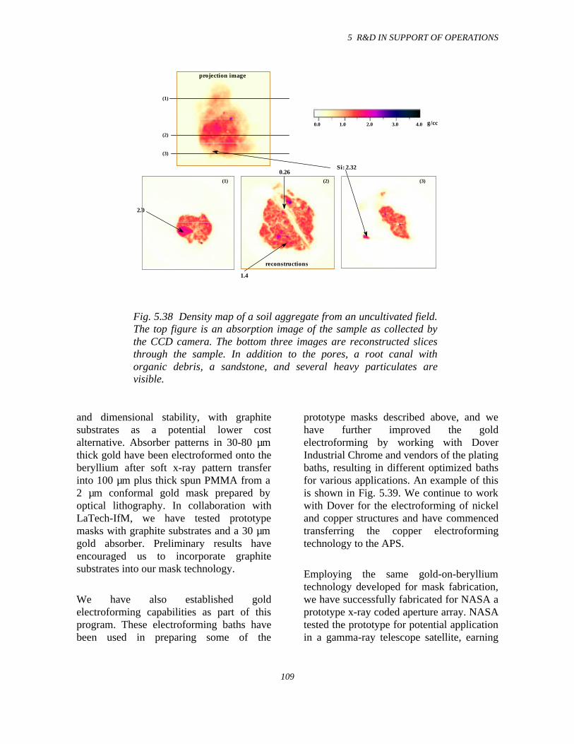
5 R&D IN SUPPORT OF OPERATIONS
109
Si: 2.32
1.4
2.0
0.26
0.0 4.01.0 2.0 3.0
(1)
(2)
(3)
(1) (2) (3)
g/cc
projection image
reconstructions
Fig. 5.38 Density map of a soil aggregate from an uncultivated field.The top figure is an absorption image of the sample as collected bythe CCD camera. The bottom three images are reconstructed slicesthrough the sample. In addition to the pores, a root canal withorganic debris, a sandstone, and several heavy particulates arevisible.
and dimensional stability, with graphitesubstrates as a potential lower costalternative. Absorber patterns in 30-80 µmthick gold have been electroformed onto theberyllium after soft x-ray pattern transferinto 100 µm plus thick spun PMMA from a2 µm conformal gold mask prepared byoptical lithography. In collaboration withLaTech-IfM, we have tested prototypemasks with graphite substrates and a 30 µmgold absorber. Preliminary results haveencouraged us to incorporate graphitesubstrates into our mask technology.
We have also established goldelectroforming capabilities as part of thisprogram. These electroforming baths havebeen used in preparing some of the
prototype masks described above, and wehave further improved the goldelectroforming by working with DoverIndustrial Chrome and vendors of the platingbaths, resulting in different optimized bathsfor various applications. An example of thisis shown in Fig. 5.39. We continue to workwith Dover for the electroforming of nickeland copper structures and have commencedtransferring the copper electroformingtechnology to the APS.
Employing the same gold-on-berylliumtechnology developed for mask fabrication,we have successfully fabricated for NASA aprototype x-ray coded aperture array. NASAtested the prototype for potential applicationin a gamma-ray telescope satellite, earning
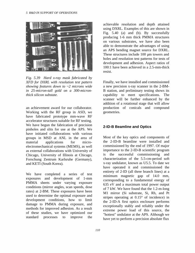
5 R&D IN SUPPORT OF OPERATIONS
110
Fig. 5.39 Hard x-ray mask fabricated byXFD for DXRL with resolution test patternshowing features down to ~2 microns widein 25-micron-tall gold on a 300-micron-thick silicon substate.
an achievement award for our collaborator.Working with the RF group in ASD, wehave fabricated prototype mm-wave RFaccelerator structures suitable for RF testing.We have begun the fabrication of precisionpinholes and slits for use at the APS. Wehave initiated collaborations with variousgroups in MSD at ANL in the area ofmaterial applications for micro-electromechanical systems (MEMS), as wellas external collaborations with University ofChicago, University of Illinois at Chicago,Forschung Zentrum Karlsruhe (Germany),and KETI (South Korea).
We have completed a series of testexposures and development of 1-mmPMMA sheets under varying exposureconditions (mirror angles, scan speeds, doserates) at 2-BM. These exposures have beenused to determine the optimal exposure anddevelopment conditions, how to limitdamage to PMMA during exposure, andmethods for improved adhesion. As a resultof these studies, we have optimized ourstandard processes to improve the
achievable resolution and depth attainedusing DXRL. Examples of this are shown inFig. 5.40 (a) and (b). By successfullyproducing 1-6 mm thick PMMA structureson various substrates, we have also beenable to demonstrate the advantages of usingan APS bending magnet source for DXRL.These structures include 100 µm towers andholes and resolution test patterns for tests ofdevelopment and adhesion. Aspect ratios of100:1 have been achieved in a 2.5-mm-thickresist.
Finally, we have installed and commissioneda new precision x-ray scanner in the 2-BM-B station, and preliminary testing shows itscapability to meet specifications. Thescanner will be further enhanced by theaddition of a rotational stage that will allowproduction of conicals and compoundgeometries.
2-ID-B Beamline and Optics
Most of the key optics and components ofthe 2-ID-B beamline were installed andcommissioned by the end of 1997. Of majorimportance to the 2-ID-B scientific programis the successful commissioning andcharacterization of the 5.5-cm-period softx-ray undulator, known as U5.5. To date wehave operated it and commissioned theentirety of 2-ID (all three branch lines) at aminimum magnetic gap of 14.0 mm,corresponding to a fundamental energy of635 eV and a maximum total power outputof 7 kW. We have found that the 1.2-m-longM1 mirror (Si substrate, Si, Rh, and Ptstripes operating at 0.15° of incidence) inthe 2-ID-A first optics enclosure performsexceptionally stably and reliably under theextreme power load of this source, the"hottest" undulator at the APS. Although wehave yet to perform a precision absolute flux
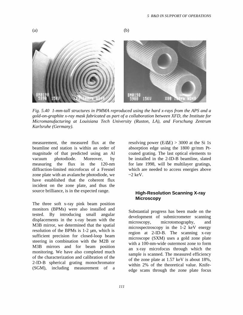
5 R&D IN SUPPORT OF OPERATIONS
111
(a) (b)
Fig. 5.40 1-mm-tall structures in PMMA reproduced using the hard x-rays from the APS and agold-on-graphite x-ray mask fabricated as part of a collaboration between XFD, the Institute forMicromanufacturing at Louisiana Tech University (Ruston, LA), and Forschung ZentrumKarlsruhe (Germany).
measurement, the measured flux at thebeamline end station is within an order ofmagnitude of that predicted using an Alvacuum photodiode. Moreover, bymeasuring the flux in the 120-nmdiffraction-limited microfocus of a Fresnelzone plate with an avalanche photodiode, wehave established that the coherent fluxincident on the zone plate, and thus thesource brilliance, is in the expected range.
The three soft x-ray pink beam positionmonitors (BPMs) were also installed andtested. By introducing small angulardisplacements in the x-ray beam with theM3B mirror, we determined that the spatialresolution of the BPMs is 1-2 µm, which issufficient precision for closed-loop beamsteering in combination with the M2B orM3B mirrors and for beam positionmonitoring. We have also completed muchof the characterization and calibration of the2-ID-B spherical grating monochromator(SGM), including measurement of a
resolving power (E/∆E) > 3000 at the Si 1sabsorption edge using the 1800 gr/mm Pt-coated grating. The last optical elements tobe installed in the 2-ID-B beamline, slatedfor late 1998, will be multilayer gratings,which are needed to access energies above~2 keV.
High-Resolution Scanning X-rayMicroscopy
Substantial progress has been made on thedevelopment of submicrometer scanningmicroscopy, microtomography, andmicrospectroscopy in the 1-2 keV energyregion at 2-ID-B. The scanning x-raymicroscope (SXM) uses a gold zone platewith a 100-nm-wide outermost zone to forman x-ray microfocus through which thesample is scanned. The measured efficiencyof the zone plate at 1.57 keV is about 18%,within 2% of the theoretical value. Knife-edge scans through the zone plate focus
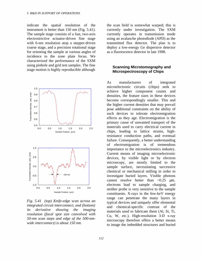
5 R&D IN SUPPORT OF OPERATIONS
112
indicate the spatial resolution of theinstrument is better than 150 nm (Fig. 5.41).The sample stage consists of a fast, two-axiselectrostrictive actuator-driven fine stagewith 6-nm resolution atop a stepper-drivencoarse stage, and a precision rotational stagefor orienting the sample at various angles ofincidence to the zone plate focus. Wecharacterized the performance of the SXMusing pinhole and grid test samples. The finestage motion is highly reproducible although
0.4
0.5
0.6
0.7
0.8
0.9
1.0
0.0 0.5 1.0 1.5 2.0 2.5
Tra
nsm
itted
Inte
nsity
(ar
b. u
nits
)
Sample Position (µm)
-1.0
-0.5
0.0
0.5
1.0
0.0 0.5 1.0 1.5 2.0 2.5
Tra
nsm
itted
Inte
nsity
(ar
b. u
nits
)
Sample Position (µm)
150 nm
Fig. 5.41 (top) Knife-edge scan across anintegrated circuit interconnect, and (bottom)its derivative showing the imagingresolution (focal spot size convolved with50-nm scan steps and edge of the 500-nm-wide interconnect) is about 150 nm.
the scan field is somewhat warped; this iscurrently under investigation. The SXMcurrently operates in transmission modeusing an avalanche photodiode (APD) as thetransmitted flux detector. The plan is todeploy a low-energy Ge dispersive detectoras a fluorescence detector in late 1998.
Scanning Microtomography andMicrospectroscopy of Chips
As manufacturers of integratedmicroelectronic circuits (chips) seek toachieve higher component counts anddensities, the feature sizes in these devicesbecome correspondingly smaller. This andthe higher current densities that may prevailpose additional constraints on the ability ofsuch devices to tolerate electromigrationeffects as they age. Electromigration is theprimary cause of unwanted transport of thematerials used to carry electrical current inchips, leading to lattice strains, high-resistance conduction paths, and eventualfailure. Consequently, a better understandingof electromigration is of tremendousimportance to the microelectronics industry.Current means of imaging microelectronicdevices, by visible light or by electronmicroscopy, are mostly limited to thesample surface, necessitating successivechemical or mechanical milling in order toinvestigate buried layers. Visible photonscannot resolve better than ~0.25 µm,electrons lead to sample charging, andneither probe is very sensitive to the sampleconstituents. X-rays in the few-keV energyrange can penetrate the many layers intypical devices and uniquely offer elementaland chemical-specific contrast of thematerials used to fabricate them (Al, Si, Ti,Cu, W, etc.). High-resolution 3-D x-raymicroscopy therefore offers a better meansto image the imbedded structures and buried
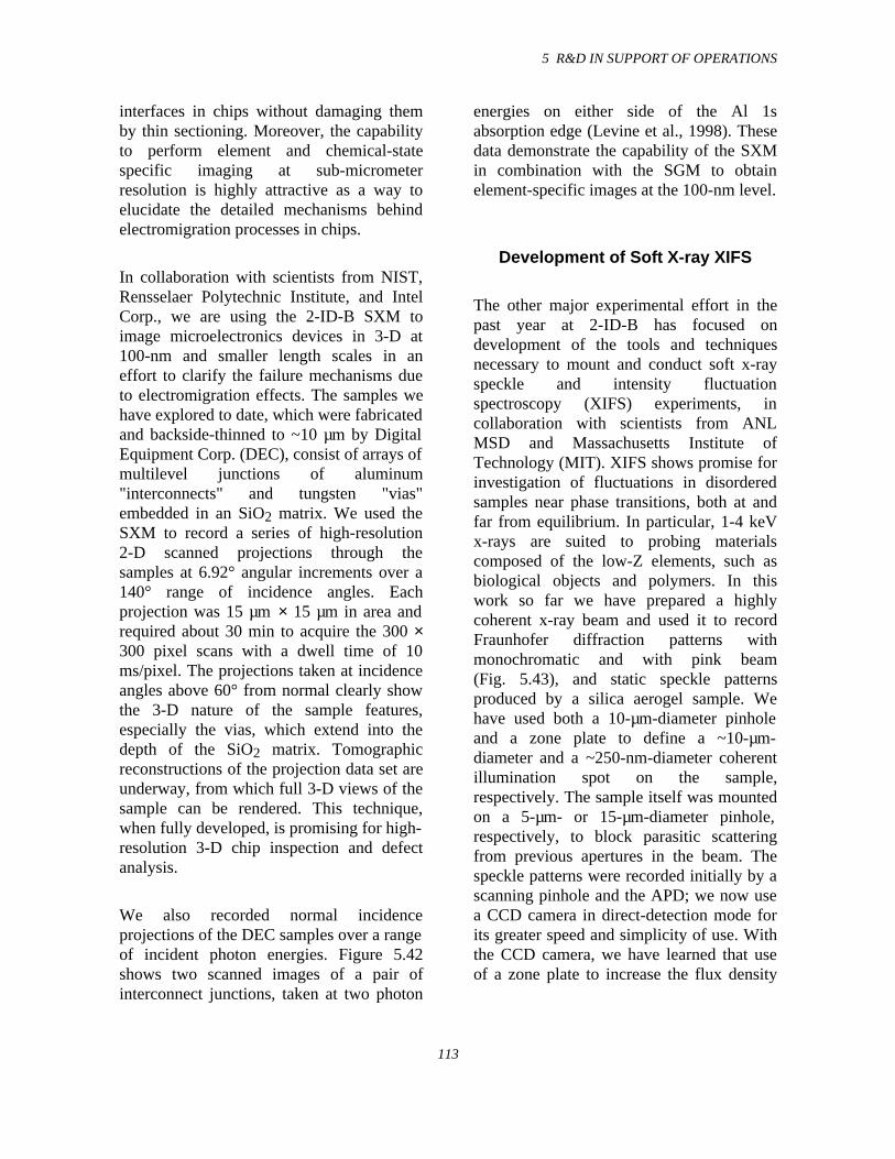
5 R&D IN SUPPORT OF OPERATIONS
113
interfaces in chips without damaging themby thin sectioning. Moreover, the capabilityto perform element and chemical-statespecific imaging at sub-micrometerresolution is highly attractive as a way toelucidate the detailed mechanisms behindelectromigration processes in chips.
In collaboration with scientists from NIST,Rensselaer Polytechnic Institute, and IntelCorp., we are using the 2-ID-B SXM toimage microelectronics devices in 3-D at100-nm and smaller length scales in aneffort to clarify the failure mechanisms dueto electromigration effects. The samples wehave explored to date, which were fabricatedand backside-thinned to ~10 µm by DigitalEquipment Corp. (DEC), consist of arrays ofmultilevel junctions of aluminum"interconnects" and tungsten "vias"embedded in an SiO2 matrix. We used theSXM to record a series of high-resolution2-D scanned projections through thesamples at 6.92° angular increments over a140° range of incidence angles. Eachprojection was 15 µm × 15 µm in area andrequired about 30 min to acquire the 300 ×300 pixel scans with a dwell time of 10ms/pixel. The projections taken at incidenceangles above 60° from normal clearly showthe 3-D nature of the sample features,especially the vias, which extend into thedepth of the SiO2 matrix. Tomographicreconstructions of the projection data set areunderway, from which full 3-D views of thesample can be rendered. This technique,when fully developed, is promising for high-resolution 3-D chip inspection and defectanalysis.
We also recorded normal incidenceprojections of the DEC samples over a rangeof incident photon energies. Figure 5.42shows two scanned images of a pair ofinterconnect junctions, taken at two photon
energies on either side of the Al 1sabsorption edge (Levine et al., 1998). Thesedata demonstrate the capability of the SXMin combination with the SGM to obtainelement-specific images at the 100-nm level.
Development of Soft X-ray XIFS
The other major experimental effort in thepast year at 2-ID-B has focused ondevelopment of the tools and techniquesnecessary to mount and conduct soft x-rayspeckle and intensity fluctuationspectroscopy (XIFS) experiments, incollaboration with scientists from ANLMSD and Massachusetts Institute ofTechnology (MIT). XIFS shows promise forinvestigation of fluctuations in disorderedsamples near phase transitions, both at andfar from equilibrium. In particular, 1-4 keVx-rays are suited to probing materialscomposed of the low-Z elements, such asbiological objects and polymers. In thiswork so far we have prepared a highlycoherent x-ray beam and used it to recordFraunhofer diffraction patterns withmonochromatic and with pink beam(Fig. 5.43), and static speckle patternsproduced by a silica aerogel sample. Wehave used both a 10-µm-diameter pinholeand a zone plate to define a ~10-µm-diameter and a ~250-nm-diameter coherentillumination spot on the sample,respectively. The sample itself was mountedon a 5-µm- or 15-µm-diameter pinhole,respectively, to block parasitic scatteringfrom previous apertures in the beam. Thespeckle patterns were recorded initially by ascanning pinhole and the APD; we now usea CCD camera in direct-detection mode forits greater speed and simplicity of use. Withthe CCD camera, we have learned that useof a zone plate to increase the flux density
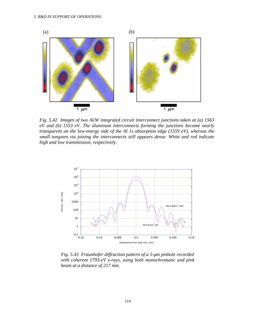
5 R&D IN SUPPORT OF OPERATIONS
114
(a) (b)
Fig. 5.42 Images of two Al/W integrated circuit interconnect junctions taken at (a) 1563eV and (b) 1553 eV. The aluminum interconnects forming the junctions become nearlytransparent on the low-energy side of the Al 1s absorption edge (1559 eV), whereas thesmall tungsten via joining the interconnects still appears dense. White and red indicatehigh and low transmission, respectively.
0.1
1
10
100
1000
10 4
10 5
10 6
10 7
-0.15 -0.10 -0.050 0.0 0.050 0.100 0.15
Inte
nsity
(a
rb.
units
)
Displacement from Optic Axis (mm)
Mono (E/∆E ~500)
Pink (E/∆E ~50)
Fig. 5.43 Fraunhofer diffraction pattern of a 5-µm pinhole recordedwith coherent 1793-eV x-rays, using both monochromatic and pinkbeam at a distance of 217 mm.
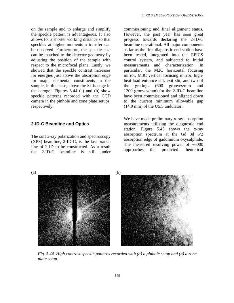
5 R&D IN SUPPORT OF OPERATIONS
115
on the sample and to enlarge and simplifythe speckle pattern is advantageous. It alsoallows for a shorter working distance so thatspeckles at higher momentum transfer canbe observed. Furthermore, the speckle sizecan be matched to the detector geometry byadjusting the position of the sample withrespect to the microfocal plane. Lastly, weshowed that the speckle contrast increasesfor energies just above the absorption edgefor major elemental constituents in thesample, in this case, above the Si 1s edge inthe aerogel. Figures 5.44 (a) and (b) showspeckle patterns recorded with the CCDcamera in the pinhole and zone plate setups,respectively.
2-ID-C Beamline and Optics
The soft x-ray polarization and spectroscopy(XPS) beamline, 2-ID-C, is the last branchline of 2-ID to be constructed. As a resultthe 2-ID-C beamline is still under
commissioning and final alignment status.However, the past year has seen greatprogress towards declaring the 2-ID-Cbeamline operational. All major componentsas far as the first diagnostic end station havebeen tested, integrated into the EPICScontrol system, and subjected to initialmeasurements and characterization. Inparticular, the M2C horizontal focusingmirror, M3C vertical focusing mirror, high-heat-load entrance slit, exit slit, and two ofthe gratings (600 grooves/mm and1200 grooves/mm) for the 2-ID-C beamlinehave been commissioned and aligned downto the current minimum allowable gap(14.0 mm) of the U5.5 undulator.
We have made preliminary x-ray absorptionmeasurements utilizing the diagnostic endstation. Figure 5.45 shows the x-rayabsorption spectrum at the Gd 3d 5/2absorption edge of gadolinium oxysulphide.The measured resolving power of ~6000approaches the predicted theoretical
(a) (b)
Fig. 5.44 High contrast speckle patterns recorded with (a) a pinhole setup and (b) a zoneplate setup.
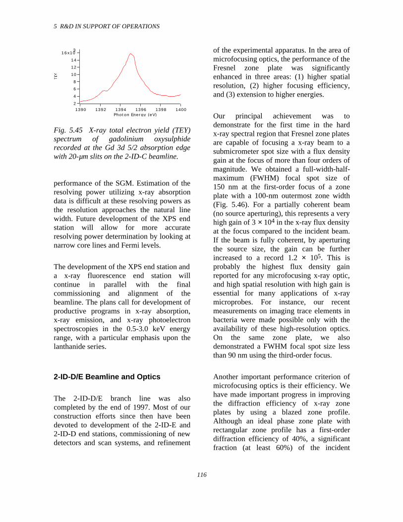
5 R&D IN SUPPORT OF OPERATIONS
116
16x103
14
12
10
8
6
4
2140013981396139413921390
Photon Energy (eV)
Fig. 5.45 X-ray total electron yield (TEY)spectrum of gadolinium oxysulphiderecorded at the Gd 3d 5/2 absorption edgewith 20-µm slits on the 2-ID-C beamline.
performance of the SGM. Estimation of theresolving power utilizing x-ray absorptiondata is difficult at these resolving powers asthe resolution approaches the natural linewidth. Future development of the XPS endstation will allow for more accurateresolving power determination by looking atnarrow core lines and Fermi levels.
The development of the XPS end station anda x-ray fluorescence end station willcontinue in parallel with the finalcommissioning and alignment of thebeamline. The plans call for development ofproductive programs in x-ray absorption,x-ray emission, and x-ray photoelectronspectroscopies in the 0.5-3.0 keV energyrange, with a particular emphasis upon thelanthanide series.
2-ID-D/E Beamline and Optics
The 2-ID-D/E branch line was alsocompleted by the end of 1997. Most of ourconstruction efforts since then have beendevoted to development of the 2-ID-E and2-ID-D end stations, commissioning of newdetectors and scan systems, and refinement
of the experimental apparatus. In the area ofmicrofocusing optics, the performance of theFresnel zone plate was significantlyenhanced in three areas: (1) higher spatialresolution, (2) higher focusing efficiency,and (3) extension to higher energies.
Our principal achievement was todemonstrate for the first time in the hardx-ray spectral region that Fresnel zone platesare capable of focusing a x-ray beam to asubmicrometer spot size with a flux densitygain at the focus of more than four orders ofmagnitude. We obtained a full-width-half-maximum (FWHM) focal spot size of150 nm at the first-order focus of a zoneplate with a 100-nm outermost zone width(Fig. 5.46). For a partially coherent beam(no source aperturing), this represents a veryhigh gain of 3 × 10⁴ in the x-ray flux densityat the focus compared to the incident beam.If the beam is fully coherent, by aperturingthe source size, the gain can be furtherincreased to a record 1.2 × 10⁵. This isprobably the highest flux density gainreported for any microfocusing x-ray optic,and high spatial resolution with high gain isessential for many applications of x-raymicroprobes. For instance, our recentmeasurements on imaging trace elements inbacteria were made possible only with theavailability of these high-resolution optics.On the same zone plate, we alsodemonstrated a FWHM focal spot size lessthan 90 nm using the third-order focus.
Another important performance criterion ofmicrofocusing optics is their efficiency. Wehave made important progress in improvingthe diffraction efficiency of x-ray zoneplates by using a blazed zone profile.Although an ideal phase zone plate withrectangular zone profile has a first-orderdiffraction efficiency of 40%, a significantfraction (at least 60%) of the incident
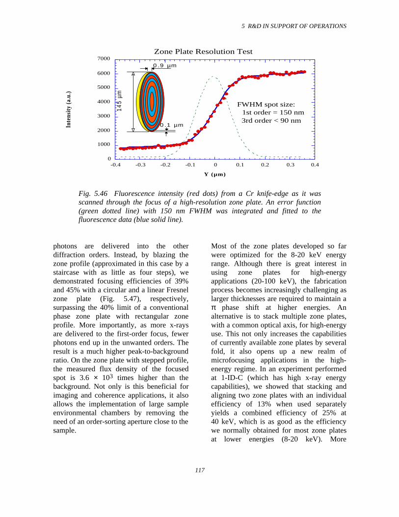
5 R&D IN SUPPORT OF OPERATIONS
117
145
µm
0.9 µm
0.1 µm
0
1000
2000
3000
4000
5000
6000
7000
-0.4 -0.3 -0.2 -0.1 0 0.1 0.2 0.3 0.4
Zone Plate Resolution Test
Inte
nsit
y (a
.u.)
Y (µm)
FWHM spot size: 1st order = 150 nm 3rd order < 90 nm
Fig. 5.46 Fluorescence intensity (red dots) from a Cr knife-edge as it wasscanned through the focus of a high-resolution zone plate. An error function(green dotted line) with 150 nm FWHM was integrated and fitted to thefluorescence data (blue solid line).
photons are delivered into the otherdiffraction orders. Instead, by blazing thezone profile (approximated in this case by astaircase with as little as four steps), wedemonstrated focusing efficiencies of 39%and 45% with a circular and a linear Fresnelzone plate (Fig. 5.47), respectively,surpassing the 40% limit of a conventionalphase zone plate with rectangular zoneprofile. More importantly, as more x-raysare delivered to the first-order focus, fewerphotons end up in the unwanted orders. Theresult is a much higher peak-to-backgroundratio. On the zone plate with stepped profile,the measured flux density of the focusedspot is 3.6 × 10³ times higher than thebackground. Not only is this beneficial forimaging and coherence applications, it alsoallows the implementation of large sampleenvironmental chambers by removing theneed of an order-sorting aperture close to thesample.
Most of the zone plates developed so farwere optimized for the 8-20 keV energyrange. Although there is great interest inusing zone plates for high-energyapplications (20-100 keV), the fabricationprocess becomes increasingly challenging aslarger thicknesses are required to maintain aπ phase shift at higher energies. Analternative is to stack multiple zone plates,with a common optical axis, for high-energyuse. This not only increases the capabilitiesof currently available zone plates by severalfold, it also opens up a new realm ofmicrofocusing applications in the high-energy regime. In an experiment performedat 1-ID-C (which has high x-ray energycapabilities), we showed that stacking andaligning two zone plates with an individualefficiency of 13% when used separatelyyields a combined efficiency of 25% at40 keV, which is as good as the efficiencywe normally obtained for most zone platesat lower energies (8-20 keV). More
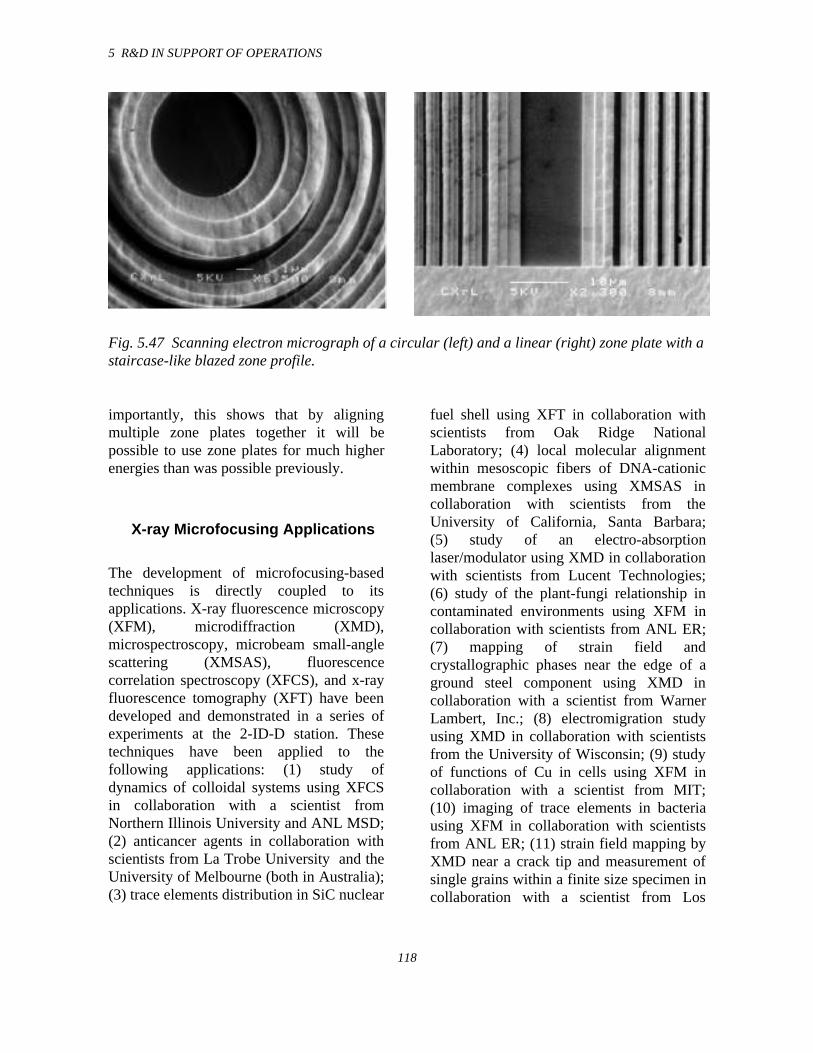
5 R&D IN SUPPORT OF OPERATIONS
118
Fig. 5.47 Scanning electron micrograph of a circular (left) and a linear (right) zone plate with astaircase-like blazed zone profile.
importantly, this shows that by aligningmultiple zone plates together it will bepossible to use zone plates for much higherenergies than was possible previously.
X-ray Microfocusing Applications
The development of microfocusing-basedtechniques is directly coupled to itsapplications. X-ray fluorescence microscopy(XFM), microdiffraction (XMD),microspectroscopy, microbeam small-anglescattering (XMSAS), fluorescencecorrelation spectroscopy (XFCS), and x-rayfluorescence tomography (XFT) have beendeveloped and demonstrated in a series ofexperiments at the 2-ID-D station. Thesetechniques have been applied to thefollowing applications: (1) study ofdynamics of colloidal systems using XFCSin collaboration with a scientist fromNorthern Illinois University and ANL MSD;(2) anticancer agents in collaboration withscientists from La Trobe University and theUniversity of Melbourne (both in Australia);(3) trace elements distribution in SiC nuclear
fuel shell using XFT in collaboration withscientists from Oak Ridge NationalLaboratory; (4) local molecular alignmentwithin mesoscopic fibers of DNA-cationicmembrane complexes using XMSAS incollaboration with scientists from theUniversity of California, Santa Barbara;(5) study of an electro-absorptionlaser/modulator using XMD in collaborationwith scientists from Lucent Technologies;(6) study of the plant-fungi relationship incontaminated environments using XFM incollaboration with scientists from ANL ER;(7) mapping of strain field andcrystallographic phases near the edge of aground steel component using XMD incollaboration with a scientist from WarnerLambert, Inc.; (8) electromigration studyusing XMD in collaboration with scientistsfrom the University of Wisconsin; (9) studyof functions of Cu in cells using XFM incollaboration with a scientist from MIT;(10) imaging of trace elements in bacteriausing XFM in collaboration with scientistsfrom ANL ER; (11) strain field mapping byXMD near a crack tip and measurement ofsingle grains within a finite size specimen incollaboration with a scientist from Los
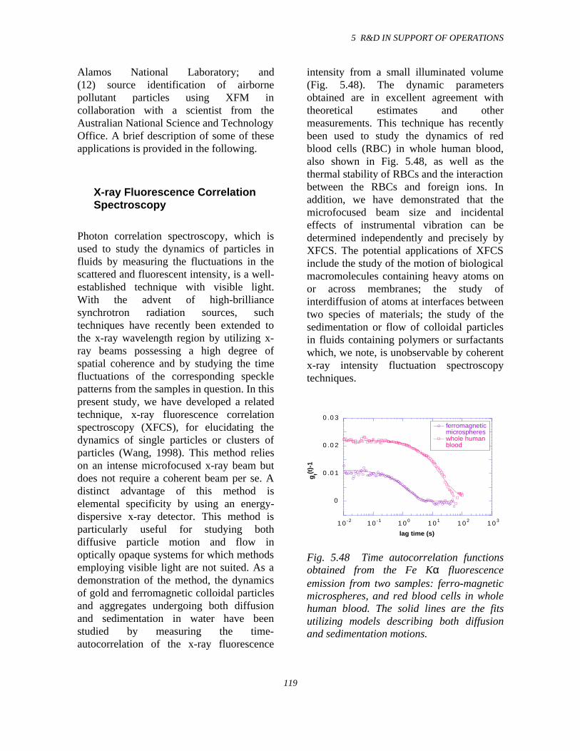
5 R&D IN SUPPORT OF OPERATIONS
119
Alamos National Laboratory; and(12) source identification of airbornepollutant particles using XFM incollaboration with a scientist from theAustralian National Science and TechnologyOffice. A brief description of some of theseapplications is provided in the following.
X-ray Fluorescence CorrelationSpectroscopy
Photon correlation spectroscopy, which isused to study the dynamics of particles influids by measuring the fluctuations in thescattered and fluorescent intensity, is a well-established technique with visible light.With the advent of high-brilliancesynchrotron radiation sources, suchtechniques have recently been extended tothe x-ray wavelength region by utilizing x-ray beams possessing a high degree ofspatial coherence and by studying the timefluctuations of the corresponding specklepatterns from the samples in question. In thispresent study, we have developed a relatedtechnique, x-ray fluorescence correlationspectroscopy (XFCS), for elucidating thedynamics of single particles or clusters ofparticles (Wang, 1998). This method relieson an intense microfocused x-ray beam butdoes not require a coherent beam per se. Adistinct advantage of this method iselemental specificity by using an energy-dispersive x-ray detector. This method isparticularly useful for studying bothdiffusive particle motion and flow inoptically opaque systems for which methodsemploying visible light are not suited. As ademonstration of the method, the dynamicsof gold and ferromagnetic colloidal particlesand aggregates undergoing both diffusionand sedimentation in water have beenstudied by measuring the time-autocorrelation of the x-ray fluorescence
intensity from a small illuminated volume(Fig. 5.48). The dynamic parametersobtained are in excellent agreement withtheoretical estimates and othermeasurements. This technique has recentlybeen used to study the dynamics of redblood cells (RBC) in whole human blood,also shown in Fig. 5.48, as well as thethermal stability of RBCs and the interactionbetween the RBCs and foreign ions. Inaddition, we have demonstrated that themicrofocused beam size and incidentaleffects of instrumental vibration can bedetermined independently and precisely byXFCS. The potential applications of XFCSinclude the study of the motion of biologicalmacromolecules containing heavy atoms onor across membranes; the study ofinterdiffusion of atoms at interfaces betweentwo species of materials; the study of thesedimentation or flow of colloidal particlesin fluids containing polymers or surfactantswhich, we note, is unobservable by coherentx-ray intensity fluctuation spectroscopytechniques.
0
0.01
0.02
0.03
10-2 10-1 100 101 102 103
ferromagneticmicrosphereswhole human blood
g f(t)-
1
lag time (s)
Fig. 5.48 Time autocorrelation functionsobtained from the Fe Kα fluorescenceemission from two samples: ferro-magneticmicrospheres, and red blood cells in wholehuman blood. The solid lines are the fitsutilizing models describing both diffusionand sedimentation motions.
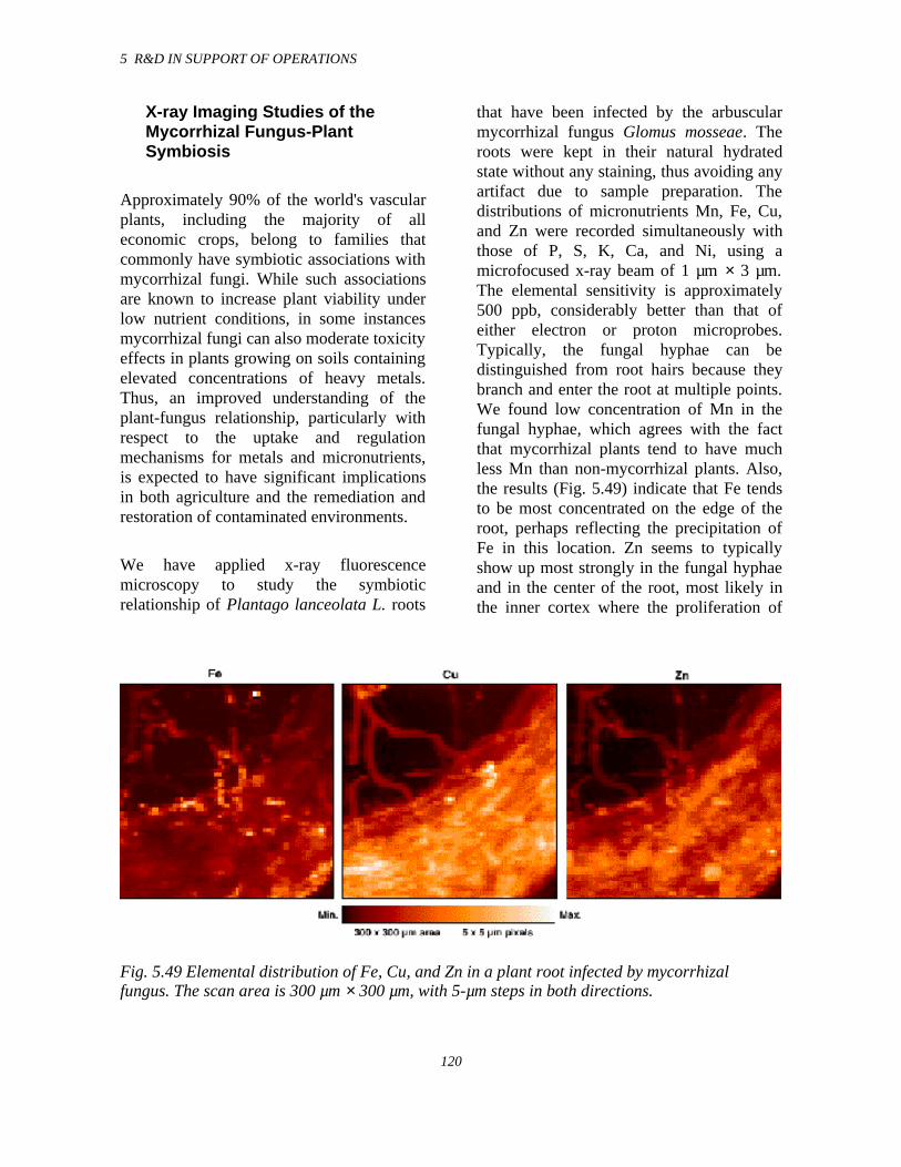
5 R&D IN SUPPORT OF OPERATIONS
120
X-ray Imaging Studies of theMycorrhizal Fungus-PlantSymbiosis
Approximately 90% of the world's vascularplants, including the majority of alleconomic crops, belong to families thatcommonly have symbiotic associations withmycorrhizal fungi. While such associationsare known to increase plant viability underlow nutrient conditions, in some instancesmycorrhizal fungi can also moderate toxicityeffects in plants growing on soils containingelevated concentrations of heavy metals.Thus, an improved understanding of theplant-fungus relationship, particularly withrespect to the uptake and regulationmechanisms for metals and micronutrients,is expected to have significant implicationsin both agriculture and the remediation andrestoration of contaminated environments.
We have applied x-ray fluorescencemicroscopy to study the symbioticrelationship of Plantago lanceolata L. roots
that have been infected by the arbuscularmycorrhizal fungus Glomus mosseae. Theroots were kept in their natural hydratedstate without any staining, thus avoiding anyartifact due to sample preparation. Thedistributions of micronutrients Mn, Fe, Cu,and Zn were recorded simultaneously withthose of P, S, K, Ca, and Ni, using amicrofocused x-ray beam of 1 µm × 3 µm.The elemental sensitivity is approximately500 ppb, considerably better than that ofeither electron or proton microprobes.Typically, the fungal hyphae can bedistinguished from root hairs because theybranch and enter the root at multiple points.We found low concentration of Mn in thefungal hyphae, which agrees with the factthat mycorrhizal plants tend to have muchless Mn than non-mycorrhizal plants. Also,the results (Fig. 5.49) indicate that Fe tendsto be most concentrated on the edge of theroot, perhaps reflecting the precipitation ofFe in this location. Zn seems to typicallyshow up most strongly in the fungal hyphaeand in the center of the root, most likely inthe inner cortex where the proliferation of
Fig. 5.49 Elemental distribution of Fe, Cu, and Zn in a plant root infected by mycorrhizalfungus. The scan area is 300 µm × 300 µm, with 5-µm steps in both directions.
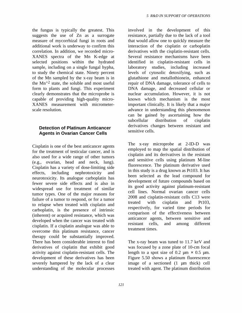
5 R&D IN SUPPORT OF OPERATIONS
121
the fungus is typically the greatest. Thissuggests the use of Zn as a surrogatemeasure of mycorrhizal fungi in roots andadditional work is underway to confirm thiscorrelation. In addition, we recorded micro-XANES spectra of the Mn K-edge atselected positions within the hydratedsample, including on a single fungal hypha,to study the chemical state. Ninety percentof the Mn sampled by the x-ray beam is inthe Mn+2 state, the soluble and most usefulform to plants and fungi. This experimentclearly demonstrates that the microprobe iscapable of providing high-quality micro-XANES measurement with micrometer-scale resolution.
Detection of Platinum AnticancerAgents in Ovarian Cancer Cells
Cisplatin is one of the best anticancer agentsfor the treatment of testicular cancer, and isalso used for a wide range of other tumors(e.g., ovarian, head and neck, lung).Cisplatin has a variety of dose-limiting sideeffects, including nephrotoxicity andneurotoxicity. Its analogue carboplatin hasfewer severe side effects and is also inwidespread use for treatment of similartumor types. One of the major reasons forfailure of a tumor to respond, or for a tumorto relapse when treated with cisplatin andcarboplatin, is the presence of intrinsic(inherent) or acquired resistance, which wasdeveloped when the cancer was treated withcisplatin. If a cisplatin analogue was able toovercome this platinum resistance, cancertherapy could be substantially improved.There has been considerable interest to findderivatives of cisplatin that exhibit goodactivity against cisplatin-resistant cells. Thedevelopment of these derivatives has beenseverely hampered by the lack of a clearunderstanding of the molecular processes
involved in the development of thisresistance, partially due to the lack of a toolthat would allow one to quickly measure theinteraction of the cisplatin or carboplatinderivatives with the cisplatin-resistant cells.Several resistance mechanisms have beenidentified in cisplatin-resistant cells inlaboratory studies, including increasedlevels of cytosolic detoxifying, such asglutathione and metallothionein, enhancedrepair of DNA damage, tolerance of cells toDNA damage, and decreased cellular ornuclear accumulation. However, it is notknown which mechanism is the mostimportant clinically. It is likely that a majoradvance in understanding this phenomenoncan be gained by ascertaining how thesubcellular distribution of cisplatinderivatives changes between resistant andsensitive cells.
The x-ray microprobe at 2-ID-D wasemployed to map the spatial distribution ofcisplatin and its derivatives in the resistantand sensitive cells using platinum M-linefluorescence. The platinum derivative usedin this study is a drug known as Pt103. It hasbeen selected as the lead compound fordevelopment of future compounds based onits good activity against platinum-resistantcell lines. Normal ovarian cancer cells2008 and cisplatin-resistant cells C13 weretreated with cisplatin and Pt103,respectively, for varied time periods forcomparison of the effectiveness betweenanticancer agents, between sensitive andresistant cells, and among differenttreatment times.
The x-ray beam was tuned to 11.7 keV andwas focused by a zone plate of 10-cm focallength to a spot size of 0.2 µm × 0.5 µm.Figure 5.50 shows a platinum fluorescenceimage of a sectioned (1 µm thick) celltreated with agent. The platinum distribution
5 R&D IN SUPPORT OF OPERATIONS
122
Fig. 5.50 Elemental distribution of Ptagent measured on a thin section (1 µmthick) of an ovarian cancer cell. The Ptdistribution is very localized. The scanarea was 40 µm × 40 µm.
is highly localized, which can provideinsights into understanding the reaction ofthe cancer cells to the agent at a subcellularlevel. In addition, we measured thefluorescence signals obtained fromindividual whole cells, thereby studying theefficiencies of cisplatin and Pt103 to 2008and C13 cells under different treatmenttimes. The results show that the Pt103derivative is five times more effective thancisplatin in platinum-resistant cells and isthree times more effective in normal2008 cancer cells after treatment for 8 and24 hours. The effectiveness of both agents in2008 and C13 cells increased as treatmenttime increased. For most of the cisplatinsamples scanned, there was a morepronounced nuclear localization than forPt103, which showed a more homogeneousdistribution. The level of platinumsensitivity was several orders of magnitudehigher than previous results obtained withthe proton microprobe PIXE. This showsthat a x-ray microprobe can provide a newtool for studying uptake of chemical agentsat the cellular and subcellular levels.
Measurement of Strain Field andCrystallographic Phases at theEdges of Steel Components
The surface hardness and fatigue resistanceof the edges of a ground component made ofmartensitic stainless steel are a function ofthe amount of retained austenite, its residualstress, and its carbide parameters. The coldwork induced by grinding causes a phasetransformation from austenite to martensite,which is associated with a volume expansionand increased residual compressive stress.The residual stress at the ground surface ofsuch components has not been measuredsuccessfully before because of the largebeam size of conventional x-ray diffractionsources. In order to optimize theperformance of these components, it isessential to establish a method to measurethe residual stress at the ground surface onmicrometer length-scales, and to understandhow the residual stress changes are relatedto the grinding process.
At beamline 2-ID-D/E, we used an x-raymicrodiffraction technique to characterizethe lattice strain distribution in thinmartensitic stainless steel components as afunction of their grinding parameters. Thelattice strain of the samples was determinedfrom CCD camera images of the x-raymicrodiffraction pattern resulting from themartensite (110) and austenite (111) planes.Micrometer-size (0.5 µm × 3 µm) areas nearthe edges of the samples were illuminatedwith a 12-keV x-ray microbeam formed witha zone plate lens. The samples were alignedsuch that the scattering vector was
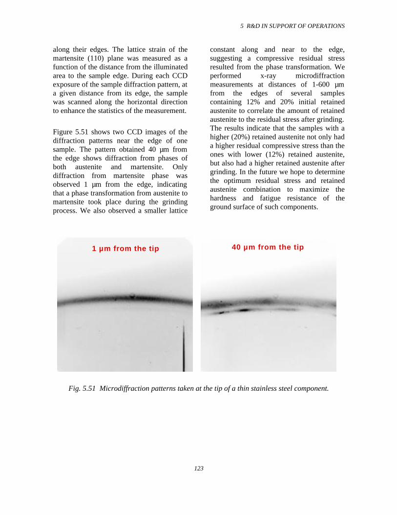
5 R&D IN SUPPORT OF OPERATIONS
123
along their edges. The lattice strain of themartensite (110) plane was measured as afunction of the distance from the illuminatedarea to the sample edge. During each CCDexposure of the sample diffraction pattern, ata given distance from its edge, the samplewas scanned along the horizontal directionto enhance the statistics of the measurement.
Figure 5.51 shows two CCD images of thediffraction patterns near the edge of onesample. The pattern obtained 40 µm fromthe edge shows diffraction from phases ofboth austenite and martensite. Onlydiffraction from martensite phase wasobserved 1 µm from the edge, indicatingthat a phase transformation from austenite tomartensite took place during the grindingprocess. We also observed a smaller lattice
constant along and near to the edge,suggesting a compressive residual stressresulted from the phase transformation. Weperformed x-ray microdiffractionmeasurements at distances of 1-600 µmfrom the edges of several samplescontaining 12% and 20% initial retainedaustenite to correlate the amount of retainedaustenite to the residual stress after grinding.The results indicate that the samples with ahigher (20%) retained austenite not only hada higher residual compressive stress than theones with lower (12%) retained austenite,but also had a higher retained austenite aftergrinding. In the future we hope to determinethe optimum residual stress and retainedaustenite combination to maximize thehardness and fatigue resistance of theground surface of such components.
1 µm from the tip 40 µm from the tip
Fig. 5.51 Microdiffraction patterns taken at the tip of a thin stainless steel component.
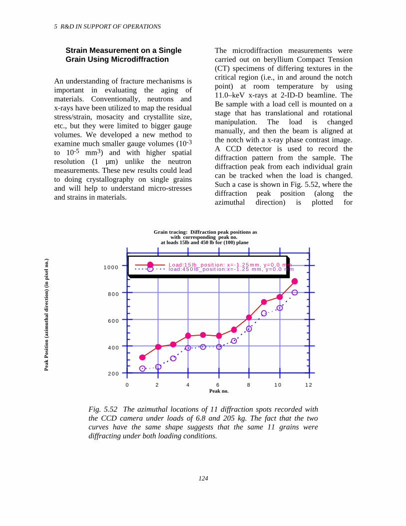
5 R&D IN SUPPORT OF OPERATIONS
124
Strain Measurement on a SingleGrain Using Microdiffraction
An understanding of fracture mechanisms isimportant in evaluating the aging ofmaterials. Conventionally, neutrons andx-rays have been utilized to map the residualstress/strain, mosacity and crystallite size,etc., but they were limited to bigger gaugevolumes. We developed a new method toexamine much smaller gauge volumes (10-3
to 10-5 mm3) and with higher spatialresolution (1 µm) unlike the neutronmeasurements. These new results could leadto doing crystallography on single grainsand will help to understand micro-stressesand strains in materials.
The microdiffraction measurements werecarried out on beryllium Compact Tension(CT) specimens of differing textures in thecritical region (i.e., in and around the notchpoint) at room temperature by using11.0–keV x-rays at 2-ID-D beamline. TheBe sample with a load cell is mounted on astage that has translational and rotationalmanipulation. The load is changedmanually, and then the beam is aligned atthe notch with a x-ray phase contrast image.A CCD detector is used to record thediffraction pattern from the sample. Thediffraction peak from each individual graincan be tracked when the load is changed.Such a case is shown in Fig. 5.52, where thediffraction peak position (along theazimuthal direction) is plotted for
200
400
600
800
1000
0 2 4 6 8 10 12
Load:15lb_position: x=-1.25mm, y=0.0 mmload:450lb_position:x=-1.25 mm, y=0.0 mm
Pea
k P
osit
ion
(azi
mut
hal d
irec
tion
) (i
n pi
xel n
o.)
Peak no.
Grain tracing: Diffraction peak positions as with corresponding peak no.
at loads 15lb and 450 lb for (100) plane
Fig. 5.52 The azimuthal locations of 11 diffraction spots recorded withthe CCD camera under loads of 6.8 and 205 kg. The fact that the twocurves have the same shape suggests that the same 11 grains werediffracting under both loading conditions.
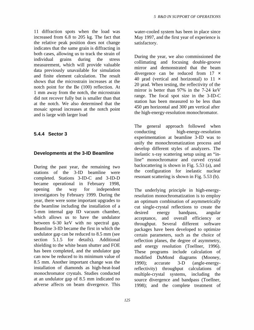
5 R&D IN SUPPORT OF OPERATIONS
125
11 diffraction spots when the load wasincreased from 6.8 to 205 kg. The fact thatthe relative peak position does not changeindicates that the same grain is diffracting inboth cases, allowing us to track the strain ofindividual grains during the stressmeasurement, which will provide valuabledata previously unavailable for simulationand finite element calculation. The resultshows that the microstrain increases at thenotch point for the Be (100) reflection. At1 mm away from the notch, the microstraindid not recover fully but is smaller than thatat the notch. We also determined that themosaic spread increases at the notch pointand is large with larger load
5.4.4 Sector 3
Developments at the 3-ID Beamline
During the past year, the remaining twostations of the 3-ID beamline werecompleted. Stations 3-ID-C and 3-ID-Dbecame operational in February 1998,opening the way for independentinvestigators by February 1999. During theyear, there were some important upgrades tothe beamline including the installation of a5-mm internal gap ID vacuum chamber,which allows us to have the undulatorbetween 6-30 keV with no spectral gap.Beamline 3-ID became the first in which theundulator gap can be reduced to 8.5 mm (seesection 5.1.5 for details). Additionalshielding to the white beam shutter and FOEhas been completed, and the undulator gapcan now be reduced to its minimum value of8.5 mm. Another important change was theinstallation of diamonds as high-heat-loadmonochromator crystals. Studies conductedat an undulator gap of 8.5 mm indicated noadverse affects on beam divergence. This
water-cooled system has been in place sinceMay 1997, and the first year of experience issatisfactory.
During the year, we also commissioned thecollimating and focusing double-groovemirror and demonstrated that the beamdivergence can be reduced from 17 ×40 µrad (vertical and horizontal) to 11 ×20 µrad. When testing, the reflectivity of themirror is better than 97% in the 7-24 keVrange. The focal spot size in the 3-ID-Cstation has been measured to be less than450 µm horizontal and 300 µm vertical afterthe high-energy-resolution monochromator.
The general approach followed whenconducting high-energy-resolutionexperimentation at beamline 3-ID was tounify the monochromatization process anddevelop different styles of analyzers. Theinelastic x-ray scattering setup using an “in-line” monochromator and curved crystalbackscattering is shown in Fig. 5.53 (a), andthe configuration for inelastic nuclearresonant scattering is shown in Fig. 5.53 (b).
The underlying principle in high-energy-resolution monochromatization is to employan optimum combination of asymmetricallycut single-crystal reflections to create thedesired energy bandpass, angularacceptance, and overall efficiency orthroughput. Several different softwarepackages have been developed to optimizecertain parameters, such as the choice ofreflection planes, the degree of asymmetry,and energy resolution (Toellner, 1996).These programs include calculation ofmodified DuMond diagrams (Mooney,1990); accurate 3-D (angle-energy-reflectivity) throughput calculations ofmultiple-crystal systems, including thesource divergence and bandpass (Toellner,1998); and the complete treatment of
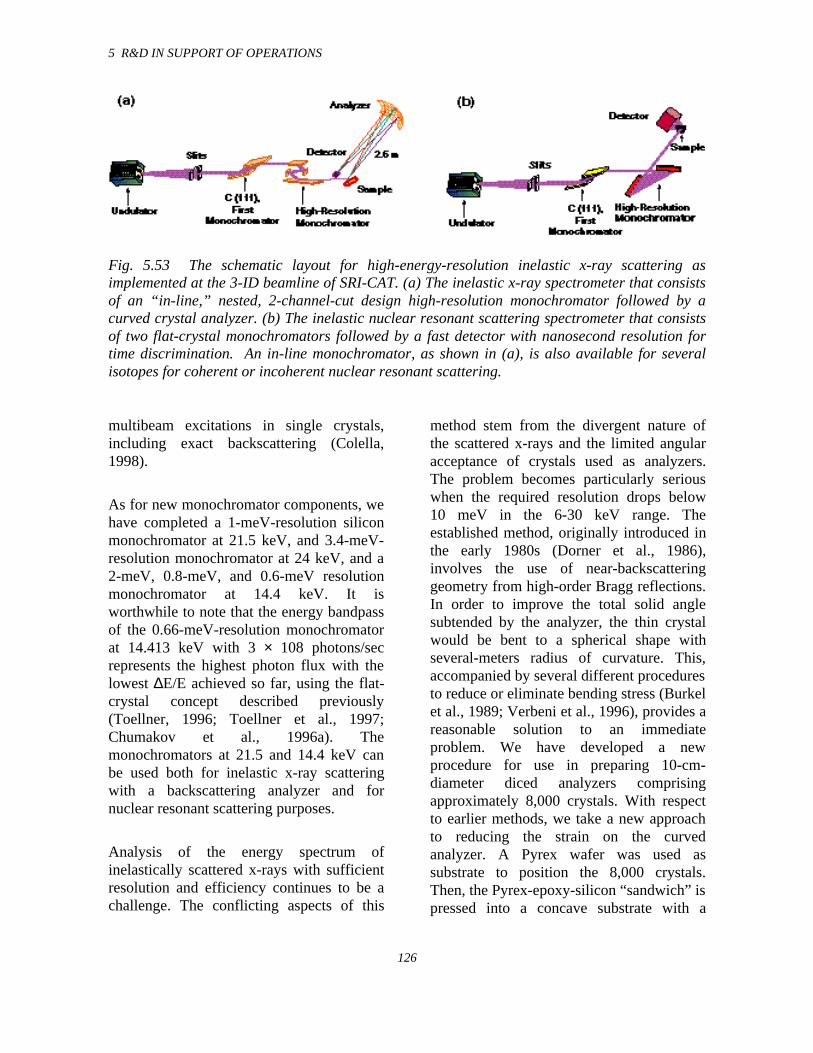
5 R&D IN SUPPORT OF OPERATIONS
126
Fig. 5.53 The schematic layout for high-energy-resolution inelastic x-ray scattering asimplemented at the 3-ID beamline of SRI-CAT. (a) The inelastic x-ray spectrometer that consistsof an “in-line,” nested, 2-channel-cut design high-resolution monochromator followed by acurved crystal analyzer. (b) The inelastic nuclear resonant scattering spectrometer that consistsof two flat-crystal monochromators followed by a fast detector with nanosecond resolution fortime discrimination. An in-line monochromator, as shown in (a), is also available for severalisotopes for coherent or incoherent nuclear resonant scattering.
multibeam excitations in single crystals,including exact backscattering (Colella,1998).
As for new monochromator components, wehave completed a 1-meV-resolution siliconmonochromator at 21.5 keV, and 3.4-meV-resolution monochromator at 24 keV, and a2-meV, 0.8-meV, and 0.6-meV resolutionmonochromator at 14.4 keV. It isworthwhile to note that the energy bandpassof the 0.66-meV-resolution monochromatorat 14.413 keV with 3 × 10⁸ photons/secrepresents the highest photon flux with thelowest ∆E/E achieved so far, using the flat-crystal concept described previously(Toellner, 1996; Toellner et al., 1997;Chumakov et al., 1996a). Themonochromators at 21.5 and 14.4 keV canbe used both for inelastic x-ray scatteringwith a backscattering analyzer and fornuclear resonant scattering purposes.
Analysis of the energy spectrum ofinelastically scattered x-rays with sufficientresolution and efficiency continues to be achallenge. The conflicting aspects of this
method stem from the divergent nature ofthe scattered x-rays and the limited angularacceptance of crystals used as analyzers.The problem becomes particularly seriouswhen the required resolution drops below10 meV in the 6-30 keV range. Theestablished method, originally introduced inthe early 1980s (Dorner et al., 1986),involves the use of near-backscatteringgeometry from high-order Bragg reflections.In order to improve the total solid anglesubtended by the analyzer, the thin crystalwould be bent to a spherical shape withseveral-meters radius of curvature. This,accompanied by several different proceduresto reduce or eliminate bending stress (Burkelet al., 1989; Verbeni et al., 1996), provides areasonable solution to an immediateproblem. We have developed a newprocedure for use in preparing 10-cm-diameter diced analyzers comprisingapproximately 8,000 crystals. With respectto earlier methods, we take a new approachto reducing the strain on the curvedanalyzer. A Pyrex wafer was used assubstrate to position the 8,000 crystals.Then, the Pyrex-epoxy-silicon “sandwich” ispressed into a concave substrate with a
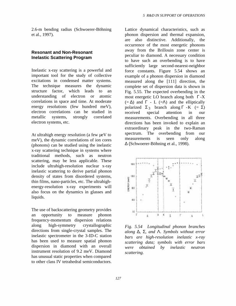
5 R&D IN SUPPORT OF OPERATIONS
127
2.6-m bending radius (Schwoerer-Böhninget al., 1997).
Resonant and Non-ResonantInelastic Scattering Program
Inelastic x-ray scattering is a powerful andimportant tool for the study of collectiveexcitations in condensed matter systems.The technique measures the dynamicstructure factor, which leads to anunderstanding of electron or atomiccorrelations in space and time. At moderateenergy resolutions (few hundred meV),electron correlations can be studied inmetallic systems, strongly correlatedelectron systems, etc.
At ultrahigh energy resolution (a few µeV tomeV), the dynamic correlations of ion cores(phonons) can be studied using the inelasticx-ray scattering technique in systems wheretraditional methods, such as neutronscattering, may be less applicable. Theseinclude ultrahigh-resolution nuclear x-rayinelastic scattering to derive partial phonondensity of states from disordered systems,thin films, nano-particles, etc. The ultrahigh-energy-resolution x-ray experiments willalso focus on the dynamics in glasses andliquids.
The use of backscattering geometry providesan opportunity to measure phononfrequency-momentum dispersion relationsalong high-symmetry crystallographicdirections from single-crystal samples. Theinelastic spectrometer in the 3-ID-C stationhas been used to measure spatial phonondispersion in diamond with an overallinstrument resolution of 9.2 meV. Diamondhas unusual static properties when comparedto other class IV tetrahedral semiconductors.
Lattice dynamical characteristics, such asphonon dispersion and thermal expansion,are also distinctive. Additionally, theoccurrence of the most energetic phononsaway from the Brillouin zone center ispeculiar to diamond. A necessary conditionto have such an overbending is to havesufficiently large second-nearest-neighborforce constants. Figure 5.54 shows anexample of a phonon dispersion in diamondmeasured along the [111] direction, thecomplete set of dispersion data is shown inFig. 5.55. The expected overbending in themost energetic LO branch along both Γ -X(= ∆) and Γ - L (=Λ) and the ellipticallypolarized Σ 3 branch along Γ - K (= Σ)received special attention in ourmeasurements. Overbending in all threedirections has been invoked to explain anextraordinary peak in the two-Ramanspectrum. The overbending from ourmeasurements is seen only along∆ (Schwoerer-Böhning et al., 1998).
Fig. 5.54 Longitudinal phonon branchesalong ∆, Σ, and Λ. Symbols without errorbars are high-resolution inelastic x-rayscattering data; symbols with error barswere obtained by inelastic neutronscattering.
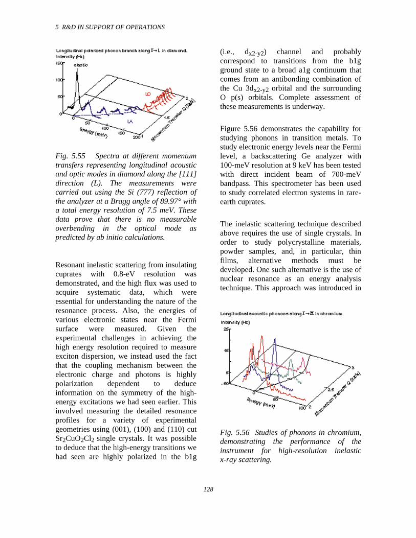
5 R&D IN SUPPORT OF OPERATIONS
128
Fig. 5.55 Spectra at different momentumtransfers representing longitudinal acousticand optic modes in diamond along the [111]direction (L). The measurements werecarried out using the Si (777) reflection ofthe analyzer at a Bragg angle of 89.97° witha total energy resolution of 7.5 meV. Thesedata prove that there is no measurableoverbending in the optical mode aspredicted by ab initio calculations.
Resonant inelastic scattering from insulatingcuprates with 0.8-eV resolution wasdemonstrated, and the high flux was used toacquire systematic data, which wereessential for understanding the nature of theresonance process. Also, the energies ofvarious electronic states near the Fermisurface were measured. Given theexperimental challenges in achieving thehigh energy resolution required to measureexciton dispersion, we instead used the factthat the coupling mechanism between theelectronic charge and photons is highlypolarization dependent to deduceinformation on the symmetry of the high-energy excitations we had seen earlier. Thisinvolved measuring the detailed resonanceprofiles for a variety of experimentalgeometries using (001), (100) and (110) cutSr2CuO2Cl2 single crystals. It was possibleto deduce that the high-energy transitions wehad seen are highly polarized in the b1g
(i.e., dx2-y2) channel and probablycorrespond to transitions from the b1gground state to a broad a1g continuum thatcomes from an antibonding combination ofthe Cu 3dx2-y2 orbital and the surroundingO p(s) orbitals. Complete assessment ofthese measurements is underway.
Figure 5.56 demonstrates the capability forstudying phonons in transition metals. Tostudy electronic energy levels near the Fermilevel, a backscattering Ge analyzer with100-meV resolution at 9 keV has been testedwith direct incident beam of 700-meVbandpass. This spectrometer has been usedto study correlated electron systems in rare-earth cuprates.
The inelastic scattering technique describedabove requires the use of single crystals. Inorder to study polycrystalline materials,powder samples, and, in particular, thinfilms, alternative methods must bedeveloped. One such alternative is the use ofnuclear resonance as an energy analysistechnique. This approach was introduced in
Fig. 5.56 Studies of phonons in chromium,demonstrating the performance of theinstrument for high-resolution inelasticx-ray scattering.
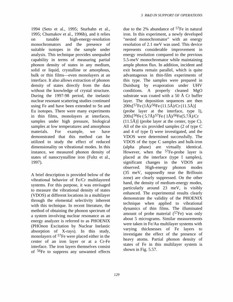
5 R&D IN SUPPORT OF OPERATIONS
129
1994 (Seto et al., 1995; Sturhahn et al.,1995; Chumakov et al., 1996b), and it relieson tunable high-energy-resolutionmonochromators and the presence ofsuitable isotopes in the sample underanalysis. This technique provides unequaledcapability in terms of measuring partialphonon density of states in any medium,solid or liquid, crystalline or amorphous,bulk or thin films—even monolayers at aninterface. It also allows extraction of phonondensity of states directly from the datawithout the knowledge of crystal structure.During the 1997-98 period, the inelasticnuclear resonant scattering studies continuedusing Fe and have been extended to Sn andEu isotopes. There were many experimentsin thin films, monolayers at interfaces,samples under high pressure, biologicalsamples at low temperatures and amorphousmaterials. For example, we havedemonstrated that this method can beutilized to study the effect of reduceddimensionality on vibrational modes. In thisinstance, we measured phonon density ofstates of nanocrystalline iron (Fultz et al.,1997).
A brief description is provided below of thevibrational behavior of Fe/Cr multilayeredsystems. For this purpose, it was envisagedto measure the vibrational density of states(VDOS) at different locations in a multilayerthrough the elemental selectivity inherentwith this technique. In recent literature, themethod of obtaining the phonon spectrum ofa system involving nuclear resonance as anenergy analyzer is referred to as PHOENIX(PHOnon Excitation by Nuclear Inelasticabsorption of X-rays). In this study,monolayers of 57Fe were placed either in thecenter of an iron layer or at a Cr-Feinterface. The iron layers themselves consistof 56Fe to suppress any unwanted effects
due to the 2% abundance of 57Fe in naturaliron. In this experiment, a newly developed"nested monochromator" with an energyresolution of 2.1 meV was used. This devicerepresents considerable improvement inenergy resolution compared to the previous5.5-meV monochromator while maintainingample photon flux. In addition, incident andexit beams remain parallel, which is quiteadvantageous in thin-film experiments ofthis type. The samples were prepared inDuisburg by evaporation under UHVconditions. A properly cleaned MgOsubstrate was coated with a 50 Å Cr bufferlayer. The deposition sequences are then200x[57Fe ( 1Å)/56Fe ( 11.5Å)/Cr ( 11.5Å)](probe layer at the interface, type I),200x[56Fe ( 5.7Å)/57Fe ( 1Å)/56Fe(5.7Å)/Cr(11.5Å)] (probe layer at the center, type C).All of the six provided samples (2 of type Cand 4 of type I) were investigated, and theVDOS were determined successfully. TheVDOS of the type C samples and bulk-iron(alpha phase) are virtually identical.However, when the 57Fe-probe layer isplaced at the interface (type I samples),significant changes in the VDOS areobserved. High-energy phonon modes(35 meV, supposedly near the Brillouinzone) are clearly suppressed. On the otherhand, the density of medium-energy modes,particularly around 23 meV, is visiblyenhanced. The experimental results clearlydemonstrate the validity of the PHOENIXtechnique when applied to vibrationaldynamics of thin films. The illuminatedamount of probe material (57Fe) was onlyabout 5 micrograms. Similar measurementswere taken in Fe/Au multilayer systems withvarying thicknesses of Fe layers toinvestigate the effect of the presence ofheavy atoms. Partial phonon density ofstates of Fe in this multilayer system isshown in Fig. 5.57.
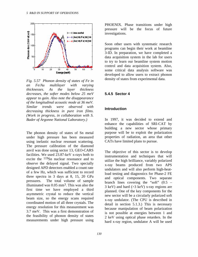
5 R&D IN SUPPORT OF OPERATIONS
130
Fig. 5.57 Phonon density of states of Fe inan Fe/Au multilayer with varyingthicknesses. As the layer thicknessdecreases, the softer modes below 25 meVappear to gain. Also note the disappearanceof the longitudinal acoustic mode at 36 meV.Similar trends were observed withdecreasing thickness in pure iron films.(Work in progress, in collaboration with S.Bader of Argonne National Laboratory.)
The phonon density of states of Sn metalunder high pressure has been measuredusing inelastic nuclear resonant scattering.The pressure calibration of the diamondanvil was done using sector 13, GEO-CARSfacilities. We used 23.87-keV x-rays both toexcite the 119Sn nuclear resonance and toobserve the delayed signal. Two speciallydesigned APD detectors enabled a count rateof a few Hz, which was sufficient to recordthree spectra in 3 days at 8, 15, 20 GPapressures. The total volume of sampleilluminated was 0.05 mm3. This was also thefirst time we have employed a thirdasymmetric crystal to reduce the verticalbeam size, so the energy scans requiredcoordinated motion of all three crystals. Theenergy resolution for this measurement was3.7 meV. This was a first demonstration ofthe feasibility of phonon density of statesmeasurements under high pressure using
PHOENIX. Phase transitions under highpressure will be the focus of futureinvestigations.
Soon other users with systematic researchprograms can begin their work at beamline3-ID. In preparation, we have completed adata acquisition system in the lab for usersto try to learn our beamline system motioncontrol and data acquisition system. Also,some critical data analysis software wasdeveloped to allow users to extract phonondensity of states from experimental data.
5.4.5 Sector 4
Introduction
In 1997, it was decided to extend andenhance the capabilities of SRI-CAT bybuilding a new sector whose primarypurpose will be to exploit the polarizationproperties of radiation, an area that otherCATs have limited plans to pursue.
The objective of this sector is to developinstrumentation and techniques that willutilize the high brilliance, variably polarizedx-ray beams produced from two APSundulators and will also perform high-heat-load testing and diagnostics for Phase-2 FEand optical components. Two separatebranch lines covering the “soft” (0.5 –3 keV) and hard (>3 keV) x-ray regions areplanned. One of the key components for thenew sector will be a circularly polarized softx-ray undulator. (The CPU is described indetail in section 5.1.3.) This is necessarybecause manipulation of beam polarizationis not possible at energies between 1 and2 keV using optical phase retarders. In thehard x-ray region, undulator A will be used
5 R&D IN SUPPORT OF OPERATIONS
131
with crystal optics, such as transmissionBragg and Bragg-Laue phase retarders.
Transferring the hard x-ray polarizationprograms from sector 1 and the soft x-rayspectroscopy program from sector 2 willallow for improved sharing of beam timeamong all four SRI-CAT sectors. It will alsogive a clearer definition of the SRI-CATsector structure. Sector 1 will specialize inhigh-energy x-ray optics development andtime-resolved experiments, sector 2 will bethe imaging and coherence techniquessector, sector 3 will remain as is: meV andnano-eV techniques, and sector 4 willbecome a polarization techniques sectorwith capabilities for testing components thathave to withstand high heat loads. Anotherimportant aspect is that SRI-CAT will beable to make efficient use of the financialcontributions from the X-ray Physics Groupand the Australian Group, giving them andoutside users improved accessibility to all ofthe SRI-CAT scientific resources.
The three major programs targeted for thisnew sector are:
1. Development of 0.4-3 keV instrumen-tation for high-spectral-resolution/ high-photon-flux polarization-dependentspectroscopy programs. This will beachieved with an elliptically polarizedundulator and a polarization-preservinggrazing-incidence monochromator. Thescientific program will cover magneticcircular dichroism (MCD), resonantmagnetic scattering, spin-resolvedphotoemission, and x-ray fluorescence.An important aspect of this program isthat this energy range covers thetransition metal and rare earth L and Medges, respectively, as well as numerousimportant elements, such as the O K, CuL, and Si K edges.
2. Development of polarizing optics andtechniques for the 3-100 keV x-rayenergy range. This program will use aplane-polarized x-ray beam fromundulator A together with polarization-manipulating crystal optics. Thescientific program will cover resonantand non-resonant magnetic scattering,magnetic circular dichroism, magneticreflectivity, and magnetic Comptonscattering.
3. Development of high-heat-load FE andoptical components for use with storagering currents up to 300 mA. Thisprogram will use an experimentalchamber as close to the shield wall aspossible for thermal cycling of FE andbeamline components.
In order to accomplish the objectives of thethree programs outlined above, the spectralrequirements outlined in Table 5.6 must bemet.
In order to provide x-rays from 0.4-100 keVwith high brilliance, two undulators will beinstalled in the sector 4 straight section.Both devices will be 2.4 m long. The hardx-ray range will be covered using undulatorA. A custom 12.8-cm-period CPU willprimarily be used for the soft x-ray range.Figure 5.6 shows the brilliance range of thesoft x-ray device in the linear polarizationmode, together with a 5.0-cm-periodelliptical device planned for the AdvancedLight Source. The 12.8-cm device has beendescribed in section 5.1.3 of this report.
A key innovation of this beamline was theproposed operation of two undulatorssimultaneously, supplying radiation to twoindependent branch lines, one for hard x-rayexperiments and the other for soft x-ray
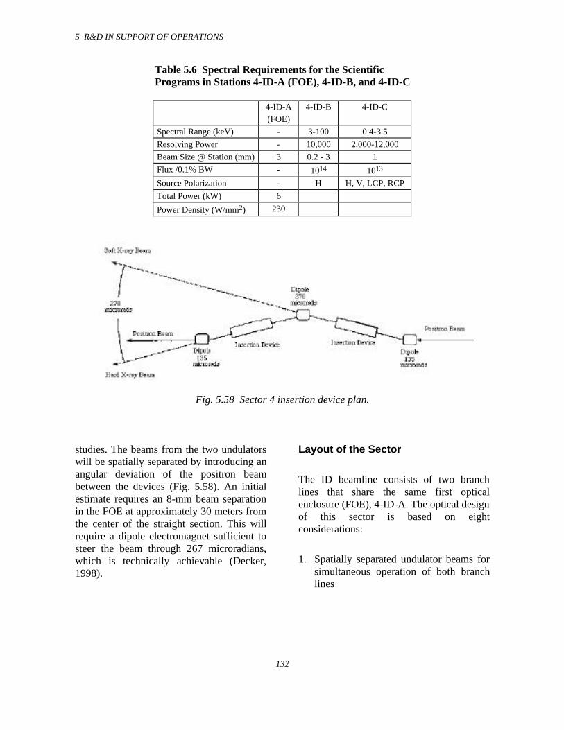
5 R&D IN SUPPORT OF OPERATIONS
132
Table 5.6 Spectral Requirements for the ScientificPrograms in Stations 4-ID-A (FOE), 4-ID-B, and 4-ID-C
4-ID-A(FOE)
4-ID-B 4-ID-C
Spectral Range (keV) - 3-100 0.4-3.5
Resolving Power - 10,000 2,000-12,000
Beam Size @ Station (mm) 3 0.2 - 3 1
Flux /0.1% BW - 1014 1013
Source Polarization - H H, V, LCP, RCP
Total Power (kW) 6
Power Density (W/mm2) 230
Fig. 5.58 Sector 4 insertion device plan.
studies. The beams from the two undulatorswill be spatially separated by introducing anangular deviation of the positron beambetween the devices (Fig. 5.58). An initialestimate requires an 8-mm beam separationin the FOE at approximately 30 meters fromthe center of the straight section. This willrequire a dipole electromagnet sufficient tosteer the beam through 267 microradians,which is technically achievable (Decker,1998).
Layout of the Sector
The ID beamline consists of two branchlines that share the same first opticalenclosure (FOE), 4-ID-A. The optical designof this sector is based on eightconsiderations:
1. Spatially separated undulator beams forsimultaneous operation of both branchlines

5 R&D IN SUPPORT OF OPERATIONS
133
2. Access to white beam (undulator A)directly adjacent to the shield wall forthermal loading tests
3. A windowless front end for access tosoft x-ray energies
4. Access to white beam in a hutch beyondthe FOE
5. A clear path beyond the white-beamhutch for possible extension of the hardx-ray branch line
6. Use of a grazing-incidence soft x-raymonochromator for presentation of thesoft x-ray source polarization
7. Simple vacuum mechanical design forminimum downtime of both lines
8. Maximum utilization of available floorspace
Layout of the ID Beamline
The ID beamline is split into two branchlines to optimize the utilization of the 0.5-30keV undulator radiation (Fig. 5.58). Therationale for this branching is described inthe first part of this section. The IDbeamline is divided into three functionalparts. The three parts are the first opticsenclosure and the two branch lines, whichare described separately below.
Beamline Branching
Our plan is to branch the two end stations,4-ID-B and 4-ID-C, by spatially separating
the undulator beams. The outboard (hardx-ray) beam will pass through the FOEundeviated to the hard x-ray white-beamstation (4-ID-B). The inboard (soft x-ray)beam will be deflected outward to branchline 4-ID-C using a pair of horizontallydeflecting mirrors. (See Fig. 5.17 for alayout of the beamline.) The incidence angleonto each mirror is 1.25° giving a totaldeflection of 5°.
Major considerations for beam branchinginclude:
• the compatibility of beamline opticalcomponents that are required for thedifferent scientific programs in termsof polarization preservation,monochromator resolving power inthe required energy range, mirrorfocusing requirements andmonochromator dispersion planerequirements; and
• the engineering and construction ofthese optical components, thermalmanagement of these optical devices,together with other aspects, such asbeamline vacuum and radiation-shielding requirements, and overalloperation of the two branches.
The hard x-ray branch line is designed forpolarization manipulation in the 3-100 keVx-ray energy range. This will be achieved byusing crystal optics following the DCM.
The soft x-ray branch line is designed topreserve the source polarization propertiesand to deliver an x-ray beam of high energyresolution in the 0.4-3.5 keV energy spectralregion. This branch will be used for high-resolution polarization-dependentspectroscopy.
5 R&D IN SUPPORT OF OPERATIONS
134
Beamline Component Test Facilitywith Movable Mask
The sector 4 FOE will also accommodate a1.75-m-long vacuum chamber for abeamline component test facility (BCTF).The chamber will be equipped with largeaccess flanges for insertion of a variety oftest components, such as white-beam photonshutter blades, white-beam masks, or white-beam slits. Numerous smaller flanges willbe used for thermocouple, electrical andwater-cooling feedthroughs, infra-redcamera and visible light viewports andactuator ports to vary the angle of incidenceon the component under test.
In order to test high-heat-load components,the BCTF chamber will be vented and thecomponent will be mounted on an actuationstage. At this time, a fixed mask and photonstop will be mounted and locked in positionon the downstream wall of the BCTFchamber. The photon stop will be designedfor a maximum 6-kW total beam power with400 W/mm2 heat flux.
Soft X-ray Horizontally DeflectingMirrors
To deliver undulator radiation to the softx-ray branch line (4-ID-C), two horizontaldeflection mirrors located at approximately29.9 meters will be inserted into the beamand will deflect the undulator radiationoutboard 5° (1.25° incidence angle ontoeach mirror).
The incidence angle of 1.25° results fromthe compromise between reasonably highreflectivity for 0.4-3.5 keV x-rays forseveral mirror materials and sufficientseparation between the two branch lines for
placement of optical elements upstream. Themirrors will be coated with Rh, which has acut-off energy of 2.6 keV. Multilayers willbe used to reach higher energies.
The maximum total power and powerdensity on the first mirror surface are 28.6W and 0.9 W/cm2, respectively. Theequivalent mirror designed for the 2-ID-Cbranch line has an absorbed power onedecade higher and a power density twodecades higher. Therefore we do notconsider this to be a concern in the sector 4design.
Hard X-ray Branch Line 4-ID-B
The hard x-ray branch line is designed forpolarization manipulation in the 3-100 keVx-ray energy range. The primary goal of thisbeamline is to use the linearly polarizedbeam from undulator A and convert it tocircularly polarized beam by using phaseretarding crystal optics. Depending on theenergy range, different schemes will be used(Lang et al., 1996). In the energy range up to20 keV, a DCM will be used in conjunctionwith either perfect diamond or silicon phaseretarders. In the energy range above 20 keV,a germanium phase retarder will be used. Amirror following the DCM will focusradiation in the vertical direction.
Double-Crystal Monochromator(DCM)
The DCM is the first optical component thatis exposed to high-heat-load conditions.Liquid nitrogen cooling of crystals will beimplemented, as in the 1-ID beamline.
5 R&D IN SUPPORT OF OPERATIONS
135
Focusing Mirror
The function of this mirror is to verticallyfocus radiation into the end station. Sincethe mirror is placed after themonochromator, substrate cooling is notrequired. The shape of the mirror iscylindrical, with a radius that can be variedin order to achieve maximum flexibility infocusing.
0.4-3.5 keV Soft X-raySpectroscopy Branch Line 4-ID-C
The 4-ID-C branch line will be dedicated tospectroscopy and instrument development inthe intermediate energy range from 0.4 to3.5 keV. The principal aim of this beamlineis to preserve the undulator sourcepolarization. It will also maximize fluxthroughput at relatively high resolvingpowers, of the order of several thousand.The source polarization will be preserved byusing grazing angles of incidence. The entirebranch line upstream and including the Y5vertical focusing mirror assembly will betransposed directly, as is, from branch line2-ID-C. The only re-engineering involvedfor this branch line will be the Y4 doublemirror assembly. Also a new vertical mirrorwill be required because of the modifiedsource-to-mirror distance, however themechanical assembly from the existingsector 2 beamline will be used.
At the end station, a flexible UHVexperimental chamber will be used.Currently a two-tier UHV experimentalchamber is under testing. This will be used
for thin film and multilayer, as well as gasphase, studies. The monochromatic beamwill enter the bottom analysis chamber,which is equipped with a Perkin Elmerhemispherical analyzer with a mean radiusof 140 mm, an acceptance angle of ± 20°and multichannel electron detector, and anelectron gun with 1000-Å beam diameter.The top preparation chamber will beequipped with a reverse-view LEED, anelectron gun and hemispherical analyzer forAuger analysis, two thin-film depositionsources, a quartz-crystal thin-film depositionmonitor, and an ion sputter gun. Thin-filmsamples prepared in the upper chamber willbe transported into the lower analysischamber by a precision 600-mm-travellinear manipulator that also has liquidnitrogen and resistive heating capabilities.An electron spin detector will be added toone of the hemispherical analyzers in thenear future. In collaboration with theadjacent imaging/coherence beamlines 2-ID-B and 2-ID-E, we also plan to implement azone-plate-based photoelectron microscopewith a spatial resolution of approximately1 micron.
A photoelectron conversion microscope witha spatial resolution of less than 20 nm is alsobeing considered. To achieve these levels ofstability, an environmental enclosure tominimize acoustic vibrations will berequired.
In May of 1998, the MOU for sector 4 wassigned and shortly thereafter constructioncommenced. The first beam in the FOE isplanned at the beginning of 1999. The sector4 construction and commissioning scheduleis presented in Table 5.7.
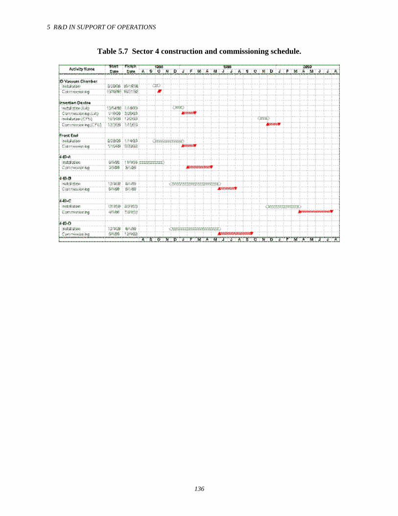
5 R&D IN SUPPORT OF OPERATIONS
136
Table 5.7 Sector 4 construction and commissioning schedule.
5 R&D IN SUPPORT OF OPERATIONS
136
5.5 References
Burkel, E., et al. (1989) SPIE Proc. Vol.1140, 426.
Cai, Z., R. J. Dejus, P. D. Hartog, Y. Feng,E. Gluskin, D. Haeffner, P. Ilinski, B. Lai,D. Legnini, E. R. Moog, S. Shastri, E.Trakhtenberg, I. Vasserman, and W. Yun(1996) Rev. Sci. Instrum. 67 (9) CD ROM.
Camley, R. E. (1989) Phys. Rev. B 39,12316.
Chumakov, A., J. Metge, A. Q. R. Baron, H.Grunsteudel, H.F. Grunsteudel, R. Ruffer,and T. Ishikawa, et al. (1996a) Nucl. Instr.Meth. A 383, 642.
Chumakov, A., A.Q. R. Baron, R. Ruffer, H.Grunsteudel, H. F. Grunsteudel, and A.Meyer (1996b) Phys. Rev. Lett. 76, 4258.
Colella, R. (1998) N-beam program (PurdueUniversity) available from J. Sutter,Argonne National Laboratory, e-mail:[email protected].
Decker, G. (1998) Argonne NationalLaboratory, unpublished information.
Dejus, R. J., B. Lai, L. Moog, E. Gluskin(1994) Undulator A Characteristics andSpecifications: Enhanced Capabilities,Argonne National Laboratory ReportANL/APS/TB-17.
Dorner, B., E. Burkel, and J. Peisl (1986)Nucl. Instr. Methods A 246, 450.
5 R&D IN SUPPORT OF OPERATIONS
137
Fultz, B., C. C. Ahn, E. E. Alp, W.Sturhahn, T. Toellner (1997) Phys. Rev. Lett79, 937.
Gluskin, E., D. Frashon, P. M. Ivanov, J.Maines, E. A. Medvedko, E. Trakhtenberg,L. R. Turner, I. Vasserman, G. I. Erg, Y. A.Evtushenko, N. G. Gavrilov, G. N.Kulipanov, A. S. Medvedko, S. P. Petrov, V.M. Popik, N. A. Vinokurov, A. Friedman, S.Krinsky, G. Rakowsky, and O. Singh (1995)The Elliptical Multipole Wiggler Project, inProceedings of the 1995 ParticleAccelerator Conference, Dallas, Texas,1426-1428.
Hahn, U., H. Schulte-Schrepping, K.Balewski, J. R. Schneider, P. Ilinski, B. Lai,W. Yun, D. Legnini, and E. Gluskin (1997)J. Synchrotron Rad. 4, 1-5.
Heidenhain GmbH, ROD 800 catalogue(1996), str. 5, D-83301 Traunreut,Deutschland.
Hewlett-Packard Co., HP-5527B catalogue(1996), S. Manhatttan Ave., Fullerton, CA92631, U.S.A.
Igor Pro, WaveMetrics, P.O. Box 2088,Lake Oswego, OR 97035, U.S.A.
Ilinski, P., W. Yun, B. Lai, E. Gluskin, andZ. Cai (1995) Rev. Sci. Instrum. 66, 1907-1909.
Ilinski, P., R. J. Dejus, E. Gluskin, T. I.Morrison (1996) Some Practical Aspects ofUndulator Radiation Properties, Optics forHigh-Brightness Synchrotron RadiationBeamlines II, SPIE Proc. Vol. 2856, 16-25.
Ilinski, P., C. T. Venkataraman, J. C. Lang,and G. Srajer (1997) Characterization of theElliptical Multipole Wiggler at theAdvanced Photon Source, SynchrotronRadiation Instrumention: Tenth U.S.National Conference, ed. E. Fontes(American Institute of Physics) pp. 49-54
Kohzu Seiki Co., Ltd., catalogue (1996), 2-27-37 Mishuku, Setagaya-ku, Tokyo 154,Japan.
Kushnir, V. I., J. P. Quintana, and P.Georgopoulus (1993) Nucl. Instrum. Meth.A328, 558.
Lang, J. C., G. Srajer, and R. J. Dejus (1996)Rev. Sci. Instrum. 67, 62-67.
LePage, J. G., and R. E. Camley (1990)Phys. Rev. Lett. 65, 1152-1155.
Levine, Z. H., A. R. Kalokin, S. P. Frigo, I.McNulty, and M. Kuhn (1998) ArgonneNational Laboratory, unpublishedinformation.
Marasinghe, G. K., M. Karabulut, C. S. Ray,D. E. Day, P. G. Allen, J. J. Bucher, D. K.Shuh, Y. Badyal, M . L. Saboungi, M.Grimsditch, S. D. Shastri, and D. R.Haeffner (1998) Argonne NationalLaboratory, unpublished information.
McLaughlin, J. C., S. L. Tagg, J. W.Zwanziger, D. R. Haeffner, and S. D. Shastri(1998) Argonne National Laboratory,unpublished information.
5 R&D IN SUPPORT OF OPERATIONS
138
Montano, P. A., G. S. Knapp, G. Jennings,E. Gluskin, E. Trakhtenberg, I. B.Vasserman, P. M. Ivanov, D. Frachon, E. R.Moog, L. R. Turner, G. K. Shenoy, M. J.Bedzyk, M. Ramanathan, M. A. Beno, andP. L. Cowan (1995) Rev. Sci. Instrum. 66,1839-1841.
Mooney, T. (1990) Program “DuMond”based on linearized Bragg equation as givenby T. J. Davis (1990) J. of X-ray Science &Tech. 2, 180.
Optodyne Inc., catalogue (1996), 1180Mahalo Place, Compton, CA 90220, U.S.A.
Rogers, C.S., D. M. Mills, W.-K. Lee, P. B.Fernandez, and T. Graber (1996) Proc. SPIEVol. 2855, 170-179.
Schwoerer-Böhning, M., P. Abbamonte, A.Macrander, and V. Kushnir (1997) SPIEProc. Vol. 3151, 282.
Schwoerer-Böhning, M., A. Macrander, andD. A. Arms (1998) Phys. Rev. Lett. 80,5572-5575.
Seto, M., Y. Yoda, S. Kikuta, X,. W. Zhang,M. Ando (1995) Phys. Rev. Lett. 74, 3828.
Shu D. (1997) Patent applied for, ANL-IN-97-004.
Smither, R. K., A. M. Khounsary, and S. Xu(1997) Proc. SPIE Vol. 3151, 150-163.
Snigirev, A., V. Kohn, I. Snigireva, and B.Lengeler (1996) Nature 384, 49.
Sturhahn, W., T. S. Toellner, E. E. Alp, X.W. Zhang, M. Ando, Y. Yoda, S. Kikuta, M.
Seto, C. W. Kimball, and B. Dabrowski(1995) Phys. Rev. Lett. 74, 3832.
Toellner, T. (1996) Ph.D. Thesis,Northwestern University.
Toellner, T. (1998) Argonne NationalLaboratory), e-mail: toellner @aps.anl.gov.
Toellner, T., M. Y. Hu, W. Sturhahn, K.Quast, and E. E. Alp (1997) Appl. Phys.Lett. 71, 2112-2114.
Verbeni, R., F. Sette, M. Krisch, U.Bergman, B. Gorges, C. Halcoussis, K.Martel, C. Masciovecchio, J. F. Ribois,G. Ruocco, and H. Sinn (1996) J. Sync. Rad.3, 426.
Wang, C., et al. (1987) Laser & Optronics p.69.
Wang, J., A. K. Sood, P. V. Satyam, Y.Feng, X.-Z. Wu, Z. Cai, W. Yun, and S. K.Sinha (1998) X-ray FluorescenceCorrelation Spectroscopy: A Method forStudying Particle Dynamics in CondensedMatter, Phys. Rev. Lett. 80, 1110-1113
Yamamoto, S., H. Kawata, H. Kitamura, M.Ando, N. Saki, and N. Shiotani (1989) Phys.Rev. Lett. 62, 2672.
Zygo Co., ZMI-1000 catalogue (1996),Laurel Brook Road, Middlefield, CN 06455,U.S.A.
6 MAJOR PLANS FOR THE FUTURE
139
6.1 Summary of Major Plans forthe Future
A summary of XFD future plans is providedbelow, which includes both short-terminitiatives and long-term strategic initiatives:
• Funds have been requested from theDOE to improve the performance ofvarious components of majorsystems, such as insertion devices,front ends, PSS, EPS, etc., that areunder XFD responsibility. Short-term needs will be supported tomaintain the reliability of operationsin order to deliver maximum beamtime to the users. These tasks willreceive the highest priority in XFDoperations workload. Theimprovements will be performedusing funds made available under theAccelerator Improvement Program.
• During FY 1998, the APS has setaside funds to design and build aliquid nitrogen distribution systemon the experiment hall floor. Thesystem will deliver liquid nitrogen toall the first optics enclosures on CATbeamlines to cool the optics. Thesystem will be built during FY 1999.
• Effort and resources will be madeavailable during FY 1999 to supportthe “top-up” mode at the APS.Implementation requires not only aclose evaluation of the impact of themode on user experiments but alsoprovision for developing requiredsystems to mitigate any difficultiesencountered by the users inperforming their experiments.
• SRI-CAT will be developing sector 4for the use of polarized x-rays. Theeffort to deliver two independentx-ray beams from two undulatorslocated on the same straight sectionto two independent beamlines posesnew technical challenges. These willbe addressed during FY 1999. Thetwo radiation sources (undulator Aand the CPU in a “dog-leg”configuration on straight-section 4 ofthe storage-ring), beamline front end,and the beamlines are planned forcommissioning in early FY 2000. Inthe future, this type of dog-legconfiguration can add an extrabeamline in any sector of the APS bythe installation of two undulatorsources canted in the horizontalplane on the same straight section.
• The beamline, front end, andundulator for COM-CAT are fundedby the State of Illinois. XFD staff areinvolved in completing theconstruction of this beamline duringFY 1999.
• The APS Phase-2, which wasdescribed in the last XFD ProgressReport 1996-97, has been submittedto the DOE. This Phase-2 initiative,in which the remaining sectors of theAPS will be fully developed, isconsistent with the recommendationsof the BESAC Panel on DOESynchrotron Sources and Science,November 1997 (chaired byR. J. Birgeneau and Z.-X. Shen).According to the plans included inthe DOE Basic Energy Sciences(BES) Facilities Roadmap (July1998, Fig. 6.1), this new initiativebegins in FY 2000 and extends
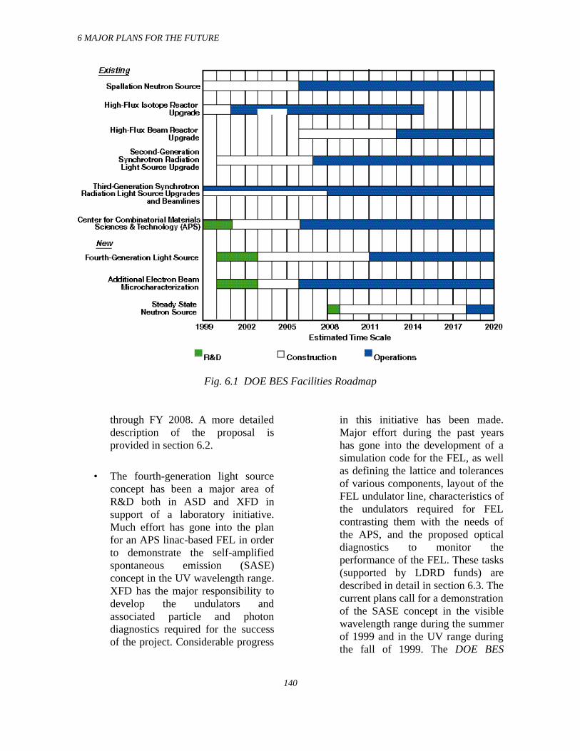
6 MAJOR PLANS FOR THE FUTURE
140
Fig. 6.1 DOE BES Facilities Roadmap
through FY 2008. A more detaileddescription of the proposal isprovided in section 6.2.
• The fourth-generation light sourceconcept has been a major area ofR&D both in ASD and XFD insupport of a laboratory initiative.Much effort has gone into the planfor an APS linac-based FEL in orderto demonstrate the self-amplifiedspontaneous emission (SASE)concept in the UV wavelength range.XFD has the major responsibility todevelop the undulators andassociated particle and photondiagnostics required for the successof the project. Considerable progress
in this initiative has been made.Major effort during the past yearshas gone into the development of asimulation code for the FEL, as wellas defining the lattice and tolerancesof various components, layout of theFEL undulator line, characteristics ofthe undulators required for FELcontrasting them with the needs ofthe APS, and the proposed opticaldiagnostics to monitor theperformance of the FEL. These tasks(supported by LDRD funds) aredescribed in detail in section 6.3. Thecurrent plans call for a demonstrationof the SASE concept in the visiblewavelength range during the summerof 1999 and in the UV range duringthe fall of 1999. The DOE BES
6 MAJOR PLANS FOR THE FUTURE
141
Facilities Roadmap (Fig. 6.1)includes a fourth-generation userfacility with R&D funds for thefacility starting in FY 2000.
• A major new initiative has beenplanned to develop a Center forCombinatorial Materials Science andTechnology that will use beamlinesin a sector at the APS. This proposalwill involve staff from both XFD andthe Materials Science Division(MSD) at ANL. The initial plan forthis center (see section 6.4) wassubmitted to the DOE and has beenwell received; DOE has included thisin the DOE BES Facilities Roadmap(Fig. 6.1). The center is expected todevelop massively paralleltechniques for complex materialssynthesis using combinatorialmethods and massively parallelphysical characterization of thematerials using microsensorsdeveloped using both deep-etchx-ray lithographic techniques andx-ray microprobes.
• Another major new laboratoryinitiative that addresses structuralgenomics is called the “IlluminatorProject” and involves staff fromXFD and the Center for MechanisticBiology and Biotechnology (CMB)at Argonne. In understanding the“blue-print” of life, the knowledge ofDNA sequence coding for thousandsof proteins is a prerequisite. Whilethe genome project has madeconsiderable progress towards thisgoal, the information is insufficientfor full understanding of human andother living systems. The knowledge
of 3–D protein structures and theirfolding patterns is an essential nextstep to make greater strides in thisfield. In this quest, there are twomajor bottlenecks in which XFDstaff plan to contribute:(a) production of thousands ofpurified crystals for structuralanalysis, and (b) measurement ofthese structures using an APSbeamline. Neither can be performedin a time efficient way with existingcapabilities. Both these bottleneckscan be overcome through thedevelopment of robotics capabilitiesfor crystal growth and operation of“smart” beamlines. In anticipation offunding support for the IlluminatorProject, the Laboratory is providingLDRD funds starting in FY 1999 toCMB and XFD to jointly pursuethese tasks (see section 6.5). Thebenefit of this R&D is expected toinfluence all disciplines representedby the APS user community inperforming research in a moreefficient fashion.
Strategic planning has been performed byXFD to develop new initiatives included inthe above list to meet future APS goals. Thisplanning has resulted in four major newinitiatives: 1) a Phase-2 plan to develop theremaining beamlines at the APS, 2) a SASEFEL, 3) a proposed Center forCombinatorial Material Science andTechnology, and 4) the Illuminator Project.The DOE BES Roadmap, shown in Fig. 6.1,includes three of the above initiatives. In thefollowing sections, brief technicaldescriptions of these four initiatives areprovided.
6 MAJOR PLANS FOR THE FUTURE
142
6.2 Phase-2 Initiative
6.2.1 Background
In the completed phase (Phase-1) of the APSProject, 40 of the 68 possible x-ray sourceshave been readied for use. Within the scopeof Phase-1 construction, IDs and beamlineFEs were built and installed by XFD so thatthe users could build 40 beamlines on theexperiment hall floor to perform research.The 40 x-ray sources to be completed inPhase-1 have already been committed totheir full use through this century by thescientific and technological users. Two moresectors have recently been awarded (SRI-CAT sector 4 and COM-CAT sector 32),which leaves 12 more sectors available forthe development of Phase-2 beamlines.Demand for beamlines spanning a widevariety of scientific disciplines continues toincrease. Many of the new users are alsoproposing technique-specific beamlines tobe developed at the APS to support nationalcommunities of users. The concept oftechnique-specific beamlines is alsoendorsed by the Birgeneau-Shen committeein their report. These new beamline facilitieswill be targeted for the most importantscience/technology goals of the U.S.research community and will be available ona peer-review or proprietary basis to allresearchers from universities, federallaboratories, and industry.
In this APS Phase-2 Initiative, 2.5-m-longand 5-m-long ID x-ray sources will be builton 12 straight sections of the APS storagering, and an additional 12 BM sources willalso be put in use. The beamline FEs forthese 24 x-ray sources will be built tocontain and safeguard access to these brightx-ray beams. In addition, funds will be
provided to build an additional six state-of-the-art technique-specific beamlines to meetscientific and technological researchdemands well into the next century. Theseinclude, for example, the demands of thebiotechnology, medical imaging,environmental science, microprobe, andhigh-energy x-ray scattering communities.
The APS Phase-2 Initiative also proposes tobuild two laboratory-office modules for theusers. These modules are similar to the sixincluded in the Phase-1 construction project.In addition, a specialized laboratory will beadded to meet specific scientific goals of theusers performing research in the areas ofcombinatorial materials research (seesection 6.4) and biotechnology (seesection 6.5).
6.2.2 Beamline Plan in the APSPhase-2 Initiative
In the APS Phase-2 Initiative, the plan is toprepare an additional 12 sectors (or24 beamlines) of the APS. There will be12 straight sections of the APS storage ringthat can accommodate IDs. It is proposedthat the IDs in six of these straight sectionswill be undulators similar to those built inthe current phase. Such sectors are referredto as Type A sectors. On the remaining sixstraight sections of the storage ring, IDs tomeet the specific needs of unique scientificand technological research communities willbe built. These technique-specific sectors arereferred to as Type B sectors and will alsoinclude the beamlines to be constructed bythe APS staff. Details of the current userstatus are given in Table 6.1.
In this new initiative, the six Type A sectorswill be completed to meet the demand of the
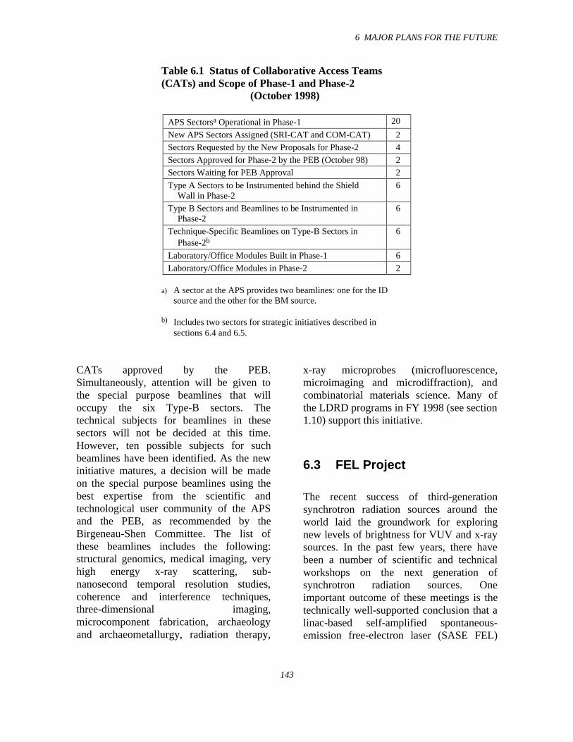
6 MAJOR PLANS FOR THE FUTURE
143
Table 6.1 Status of Collaborative Access Teams(CATs) and Scope of Phase-1 and Phase-2
(October 1998)
APS Sectorsa Operational in Phase-1 20
New APS Sectors Assigned (SRI-CAT and COM-CAT) 2
Sectors Requested by the New Proposals for Phase-2 4
Sectors Approved for Phase-2 by the PEB (October 98) 2
Sectors Waiting for PEB Approval 2
Type A Sectors to be Instrumented behind the ShieldWall in Phase-2
6
Type B Sectors and Beamlines to be Instrumented inPhase-2
6
Technique-Specific Beamlines on Type-B Sectors inPhase-2b
6
Laboratory/Office Modules Built in Phase-1 6
Laboratory/Office Modules in Phase-2 2
a) A sector at the APS provides two beamlines: one for the IDsource and the other for the BM source.
b) Includes two sectors for strategic initiatives described insections 6.4 and 6.5.
CATs approved by the PEB.Simultaneously, attention will be given tothe special purpose beamlines that willoccupy the six Type-B sectors. Thetechnical subjects for beamlines in thesesectors will not be decided at this time.However, ten possible subjects for suchbeamlines have been identified. As the newinitiative matures, a decision will be madeon the special purpose beamlines using thebest expertise from the scientific andtechnological user community of the APSand the PEB, as recommended by theBirgeneau-Shen Committee. The list ofthese beamlines includes the following:structural genomics, medical imaging, veryhigh energy x-ray scattering, sub-nanosecond temporal resolution studies,coherence and interference techniques,three-dimensional imaging,microcomponent fabrication, archaeologyand archaeometallurgy, radiation therapy,
x-ray microprobes (microfluorescence,microimaging and microdiffraction), andcombinatorial materials science. Many ofthe LDRD programs in FY 1998 (see section1.10) support this initiative.
6.3 FEL Project
The recent success of third-generationsynchrotron radiation sources around theworld laid the groundwork for exploringnew levels of brightness for VUV and x-raysources. In the past few years, there havebeen a number of scientific and technicalworkshops on the next generation ofsynchrotron radiation sources. Oneimportant outcome of these meetings is thetechnically well-supported conclusion that alinac-based self-amplified spontaneous-emission free-electron laser (SASE FEL)
6 MAJOR PLANS FOR THE FUTURE
144
could represent a future fourth-generationsynchrotron radiation source.
Several laboratories around the world,including the APS, recently startedconstruction of SASE FELs for theVUV/x-ray wavelength range. The APSSASE FEL would consist of two majorparts: the 600-MeV linac equipped with asmall-emittance electron gun, and a set oftwelve undulators that would generate andfinally lase VUV radiation. Initially,operations will be at a lower energy in orderto produce light at a visible wavelength.This relaxes requirements for the electronbeam, undulator, and diagnostics. Afterexperience is gained at 510 nm, the linacenergy will be increased to achieve SASEoperation at 120 nm. This entire project issupported by LDRD funds.
XFD is responsible for the design,construction and commissioning of theundulator line of the APS SASE FEL, whileASD is responsible for delivering theelectron beam. For the XFD staff, the SASEFEL project is a very natural continuation ofthe ID development process that has beenquite extensive during the entire APSproject. As of summer 1998, there are22 IDs installed in the APS storage ring, asdescribed in section 5.1 of this report. Theuniquely equipped ID MagneticMeasurement Facility and innovativemethods of magnetic tuning provide a solidbase of support for the state-of-the-artperformance of APS IDs. Also, x-raydiagnostic techniques developed andimplemented at the APS permit independentverification and confirmation of IDperformance. All this expertise is essentialin beginning development of a newgeneration of synchrotron radiation sources.
The main difference between thedevelopment of IDs for the APS storage ringand for the FEL is the integration process.While IDs for the APS storage ring must beintegrated into the existing magnetic latticeof the machine, the FEL IDs themselves arethe lattice, and therefore the choice oflattice, in most cases, lies in the hands of theID developers. With this choice comes theresponsibility for justifying the lattice andthe ID specifications. In order to accomplishthis task, new codes for the simulation ofSASE FEL performance have been writtenand extensively tested, and the results werefound to agree with results from previousSASE FEL codes.
Once the new codes were validated, theirefficiency and flexibility were used todetermine that the magnetic lattice for theAPS SASE FEL could be based on aseparated functions approach, i.e., theundulators and quadrupole lenses do notneed to be combined in the same magneticelement. The calculated FEL output poweris not affected significantly by the choice ofcombined or separated focusing functions inthe magnetic lattice. This crucial resultbrings extremely critical simplifications tothe FEL undulator design, in that the well-developed and well-proven approach used inthe design and construction of the APS IDscan be applied to the SASE FEL. Inaddition, conventional beam diagnostics canbe placed along with the quadrupoles in thebreaks between separated IDs.
6.3.1 FEL Computer Code
A computer code was developed toinvestigate important design considerationsfor the APS FEL. For example, the
6 MAJOR PLANS FOR THE FUTURE
145
possibility of the horizontal focusing beingseparate from the undulator was studied,and, more recently, mechanical toleranceshave been determined. The code numericallyintegrates the equation derived byVinokurov (1996) to determine the electrondistribution function in a high-gain FEL.The ability to handle longitudinallyinhomogeneous magnetic systems, such asseparated undulator segments withquadrupole focusing lenses inserted in thebreaks between undulators, was specificallybuilt into the code. For the case of acontinuous undulator, verifications againstsemianalytical expressions and other codes,such as GINGER and TDA3D, have beenperformed, with very good agreement in allcases.
The results of calculations that looked at thedifference between a continuous undulatorand separated undulator segments withhorizontally focusing quadrupoles betweenthe segments are shown in Fig. 6.2. Thepower output of the FEL is proportional tothe modulus, squared, of the electron bunchpeak current density. This quantity isexpected to grow exponentially for a perfectcontinuous undulator, with horizontalfocusing provided by shaping of the poletips. The dotted line in the top panel ofFig. 6.2 is indeed a straight line, as expectedfor a log plot. The solid line shows the resultof the simulation for the planned APS FELdesign. The amplification is reduced due tothe breaks between undulators, but thereduction of ln(|J|2) is the ratio of the breaklength to the cell (i.e., undulator plus break)length. Thus, the electron bunch peakcurrent density is not adversely affected by alattice with separate function elements. Noextra undulator magnetic structure length isneeded to compensate for loss of gain in thebreaks. The lower panel of Fig. 6.2 shows
the scaling factor F, which is inverselyproportional to the power gain length. Theintegral of F is also proportional to ln(|J|2).
The calculations were performed at a beamenergy of 220 MeV for a beam emittance of2.50 × 10-8 m-rad (for both the horizontaland vertical directions), and a beam energyspread (s.d.) of 0.15%. The undulatorperiod length was 3.30 cm, and the totallength of one undulator segment was2.3265 m (70.5 periods). The break lengthwas fixed at 36.5 cm with a singlehorizontally focusing quadrupole (off-centered longitudinally by 8.0 cm, and focallength 1.00 m) in each break. The undulatorK values were 3.10. These parameters give afundamental harmonic in the visible lightrange (5168 Å). (This differs slightly fromthe plan for the APS FEL, which is to adjustthe beam energy slightly away from220 MeV in order to have a fundamentalharmonic of 5100 Å.) The undulators wereperfectly aligned, the incident beam wascentered, and matched beam parameters atthe entrance were used.
We have also examined beam andmechanical tolerances and were able todetermine the full set of necessaryspecifications. The misalignments of oneundulator with respect to adjacentundulators were simulated, and thesensitivity to unmatched beam parameters(the Twiss parameters α and β) at theentrance and to a noncentered incident beam(xo, xo’, yo, yo’) were checked (for a fullreport see Dejus and Vasserman, 1998). Thecalculated tolerances given in Table 6.2 arebased on requiring that the power output notchange more than approximately 10% for agiven parameter.
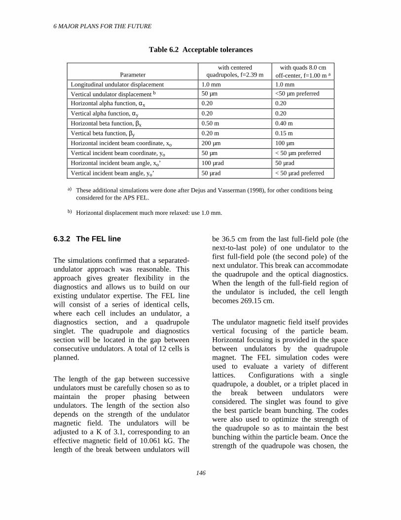
6 MAJOR PLANS FOR THE FUTURE
146
Table 6.2 Acceptable tolerances
Parameterwith centered
quadrupoles, f=2.39 mwith quads 8.0 cm
off-center, f=1.00 m a
Longitudinal undulator displacement 1.0 mm 1.0 mm
Vertical undulator displacement b 50 µm <50 µm preferred
Horizontal alpha function, αx 0.20 0.20
Vertical alpha function, αy 0.20 0.20
Horizontal beta function, βx 0.50 m 0.40 m
Vertical beta function, βy 0.20 m 0.15 m
Horizontal incident beam coordinate, xo 200 µm 100 µm
Vertical incident beam coordinate, yo 50 µm < 50 µm preferred
Horizontal incident beam angle, xo’ 100 µrad 50 µrad
Vertical incident beam angle, yo’ 50 µrad < 50 µrad preferred
a) These additional simulations were done after Dejus and Vasserman (1998), for other conditions beingconsidered for the APS FEL.
b) Horizontal displacement much more relaxed: use 1.0 mm.
6.3.2 The FEL line
The simulations confirmed that a separated-undulator approach was reasonable. Thisapproach gives greater flexibility in thediagnostics and allows us to build on ourexisting undulator expertise. The FEL linewill consist of a series of identical cells,where each cell includes an undulator, adiagnostics section, and a quadrupolesinglet. The quadrupole and diagnosticssection will be located in the gap betweenconsecutive undulators. A total of 12 cells isplanned.
The length of the gap between successiveundulators must be carefully chosen so as tomaintain the proper phasing betweenundulators. The length of the section alsodepends on the strength of the undulatormagnetic field. The undulators will beadjusted to a K of 3.1, corresponding to aneffective magnetic field of 10.061 kG. Thelength of the break between undulators will
be 36.5 cm from the last full-field pole (thenext-to-last pole) of one undulator to thefirst full-field pole (the second pole) of thenext undulator. This break can accommodatethe quadrupole and the optical diagnostics.When the length of the full-field region ofthe undulator is included, the cell lengthbecomes 269.15 cm.
The undulator magnetic field itself providesvertical focusing of the particle beam.Horizontal focusing is provided in the spacebetween undulators by the quadrupolemagnet. The FEL simulation codes wereused to evaluate a variety of differentlattices. Configurations with a singlequadrupole, a doublet, or a triplet placed inthe break between undulators wereconsidered. The singlet was found to givethe best particle beam bunching. The codeswere also used to optimize the strength ofthe quadrupole so as to maintain the bestbunching within the particle beam. Once thestrength of the quadrupole was chosen, the
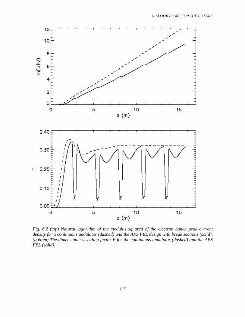
6 MAJOR PLANS FOR THE FUTURE
147
Fig. 6.2 (top) Natural logarithm of the modulus squared of the electron bunch peak currentdensity for a continuous undulator (dashed) and the APS FEL design with break sections (solid).(bottom) The dimensionless scaling factor F for the continuous undulator (dashed) and the APSFEL (solid).
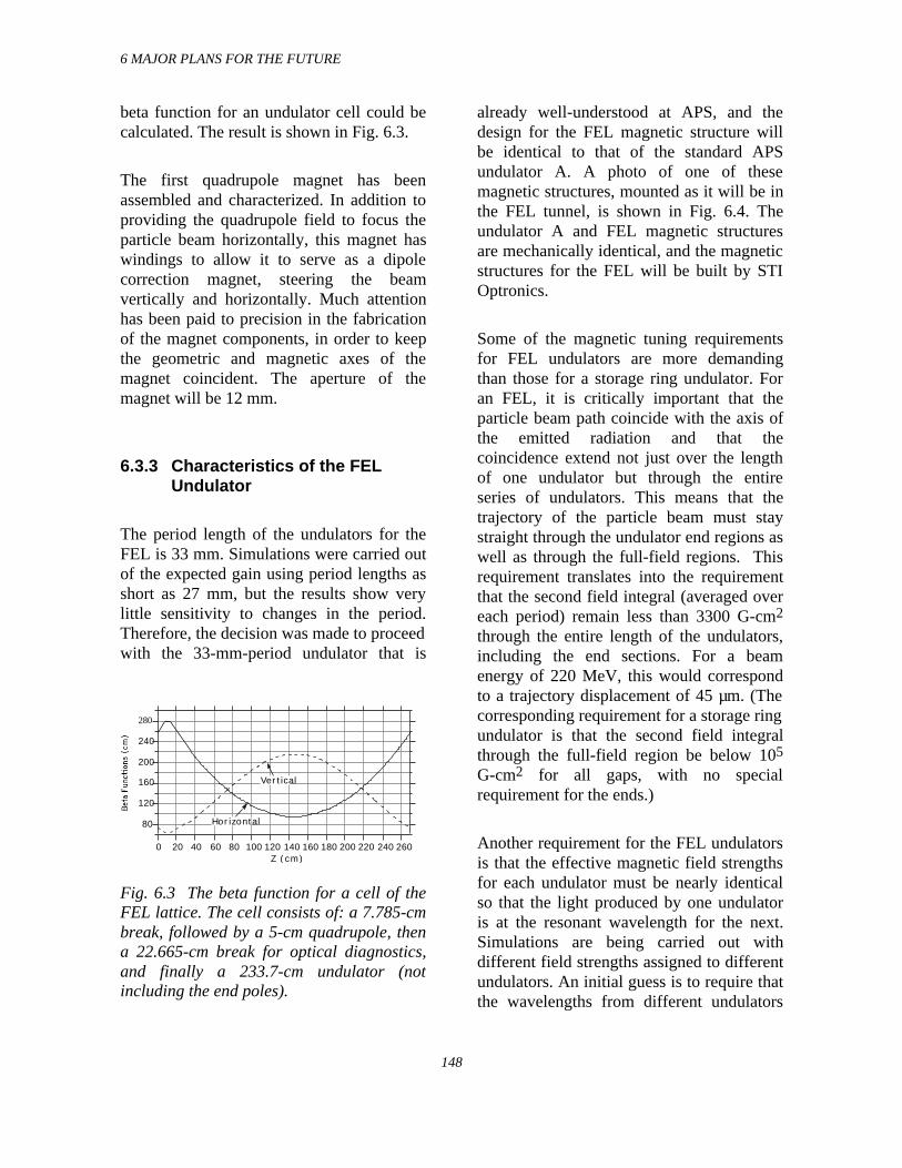
6 MAJOR PLANS FOR THE FUTURE
148
beta function for an undulator cell could becalculated. The result is shown in Fig. 6.3.
The first quadrupole magnet has beenassembled and characterized. In addition toproviding the quadrupole field to focus theparticle beam horizontally, this magnet haswindings to allow it to serve as a dipolecorrection magnet, steering the beamvertically and horizontally. Much attentionhas been paid to precision in the fabricationof the magnet components, in order to keepthe geometric and magnetic axes of themagnet coincident. The aperture of themagnet will be 12 mm.
6.3.3 Characteristics of the FELUndulator
The period length of the undulators for theFEL is 33 mm. Simulations were carried outof the expected gain using period lengths asshort as 27 mm, but the results show verylittle sensitivity to changes in the period.Therefore, the decision was made to proceedwith the 33-mm-period undulator that is
280
240
200
160
120
80
260240220200180160140120100806040200Z (cm)
Horizontal
Vertical
Fig. 6.3 The beta function for a cell of theFEL lattice. The cell consists of: a 7.785-cmbreak, followed by a 5-cm quadrupole, thena 22.665-cm break for optical diagnostics,and finally a 233.7-cm undulator (notincluding the end poles).
already well-understood at APS, and thedesign for the FEL magnetic structure willbe identical to that of the standard APSundulator A. A photo of one of thesemagnetic structures, mounted as it will be inthe FEL tunnel, is shown in Fig. 6.4. Theundulator A and FEL magnetic structuresare mechanically identical, and the magneticstructures for the FEL will be built by STIOptronics.
Some of the magnetic tuning requirementsfor FEL undulators are more demandingthan those for a storage ring undulator. Foran FEL, it is critically important that theparticle beam path coincide with the axis ofthe emitted radiation and that thecoincidence extend not just over the lengthof one undulator but through the entireseries of undulators. This means that thetrajectory of the particle beam must staystraight through the undulator end regions aswell as through the full-field regions. Thisrequirement translates into the requirementthat the second field integral (averaged overeach period) remain less than 3300 G-cm2
through the entire length of the undulators,including the end sections. For a beamenergy of 220 MeV, this would correspondto a trajectory displacement of 45 µm. (Thecorresponding requirement for a storage ringundulator is that the second field integralthrough the full-field region be below 105
G-cm2 for all gaps, with no specialrequirement for the ends.)
Another requirement for the FEL undulatorsis that the effective magnetic field strengthsfor each undulator must be nearly identicalso that the light produced by one undulatoris at the resonant wavelength for the next.Simulations are being carried out withdifferent field strengths assigned to differentundulators. An initial guess is to require thatthe wavelengths from different undulators
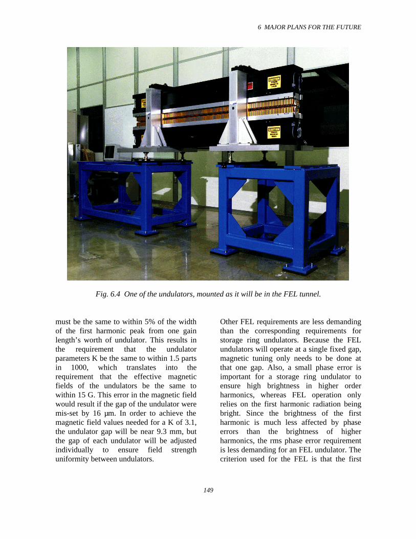
6 MAJOR PLANS FOR THE FUTURE
149
Fig. 6.4 One of the undulators, mounted as it will be in the FEL tunnel.
must be the same to within 5% of the widthof the first harmonic peak from one gainlength’s worth of undulator. This results inthe requirement that the undulatorparameters K be the same to within 1.5 partsin 1000, which translates into therequirement that the effective magneticfields of the undulators be the same towithin 15 G. This error in the magnetic fieldwould result if the gap of the undulator weremis-set by 16 µm. In order to achieve themagnetic field values needed for a K of 3.1,the undulator gap will be near 9.3 mm, butthe gap of each undulator will be adjustedindividually to ensure field strengthuniformity between undulators.
Other FEL requirements are less demandingthan the corresponding requirements forstorage ring undulators. Because the FELundulators will operate at a single fixed gap,magnetic tuning only needs to be done atthat one gap. Also, a small phase error isimportant for a storage ring undulator toensure high brightness in higher orderharmonics, whereas FEL operation onlyrelies on the first harmonic radiation beingbright. Since the brightness of the firstharmonic is much less affected by phaseerrors than the brightness of higherharmonics, the rms phase error requirementis less demanding for an FEL undulator. Thecriterion used for the FEL is that the first
6 MAJOR PLANS FOR THE FUTURE
150
harmonic intensity should not decrease bymore than 5% due to phase errors. Thisleads to the requirement that the rms phaseerror be less than 10°.
6.3.4 The Optical Diagnostics
The diagnostics serve two purposes: 1) tomonitor and maintain the alignment betweenthe particle beam and the undulatorradiation, and 2) to evaluate thecharacteristics of the light that is producedby the FEL.
A schematic of the diagnostics section thatwill be located between the undulators isshown in Fig. 6.5. Since it is critical that theparticle beam and the axis of the emittedlight beam coincide through the entire seriesof undulators, three different andcomplementary monitors of the particlebeam position have been included. Thecapacitive button BPM, or beam positionmonitor, is the same as the BPMs used at theends of the insertion device straight sectionsin the APS storage ring. The relativepositions of the buttons are different than inthe storage ring; however, because the FELvacuum chamber has a smaller verticalaperture than the usual storage ring IDvacuum chamber, the buttons will bevertically closer. They will also be closertransversely in order to improve theirsensitivity. The wire BPM is an absoluteposition monitor that consists of twoperpendicular sets of four parallel wires. Thewires are spaced 0.5 mm apart and have adiameter of 15 µm. The current toindividual wires is monitored as the particlebeam is steered to strike the wires. Thebeam can be centered vertically andhorizontally by determining where it hits thewires on opposite sides of the beam centerline and splitting the difference. During
normal operation the beam will not strikethe wires because the spacing between wireswill be a few times the beam size. The thirdbeam position monitor is the YAGscintillator crystal. The optics that will beused to image the YAG crystal will give a1:1-sized image of the YAG crystal on aCCD camera, so that the 6.5 × 6.25 µm pixelsize will be the resolution at the crystal.Therefore, the optical resolution will becomparable to the 10 µm resolution reportedfor the YAG crystal itself (Safranek andStefan, 1996).
Upstream of the undulators, there will be achicane for the particle beam. Thesynchrotron radiation produced at its bendswill be monitored as a means ofcharacterizing the particle beam, and it willalso provide a place for an alignment laser tobe inserted. The alignment laser will bedirected down the inside of the vacuumchamber and will be used to define thedesired straight-line beam path. Since thealignment laser light will travel through thesame optical systems as the FEL light andthe light from the YAG crystal, the desiredposition of the light on the CCD arrays canbe defined.
In order to relate the overlap between theparticle and emitted light beams inside theundulators to where it is measured betweenthe undulators, it is convenient to requirethat the particle beam stay in a straight line,with no displacements or deflections,through the ends of the undulators. (Theparticle beam needs to be straight throughthe length of the full-field region of theundulators in any case.) Because no positionmonitors will be located inside theundulators themselves, careful magneticcharacterization and tuning of the undulatorswill ensure the straightness of the trajectorythrough the ends as well as through the full-
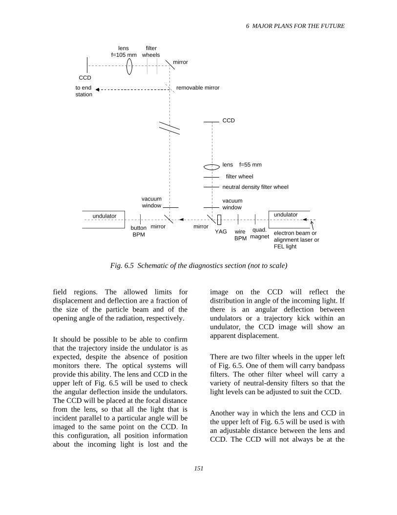
6 MAJOR PLANS FOR THE FUTURE
151
CCD
lensf=105 mm
vacuumwindow
mirror
mirror
removable mirror
undulator
filterwheels
to endstation
electron beam oralignment laser orFEL light
CCD
lens f=55 mm
vacuumwindow
YAGmirror
neutral density filter wheel
filter wheel
wireBPM
buttonBPM
quad.magnet
undulator
Fig. 6.5 Schematic of the diagnostics section (not to scale)
field regions. The allowed limits fordisplacement and deflection are a fraction ofthe size of the particle beam and of theopening angle of the radiation, respectively.
It should be possible to be able to confirmthat the trajectory inside the undulator is asexpected, despite the absence of positionmonitors there. The optical systems willprovide this ability. The lens and CCD in theupper left of Fig. 6.5 will be used to checkthe angular deflection inside the undulators.The CCD will be placed at the focal distancefrom the lens, so that all the light that isincident parallel to a particular angle will beimaged to the same point on the CCD. Inthis configuration, all position informationabout the incoming light is lost and the
image on the CCD will reflect thedistribution in angle of the incoming light. Ifthere is an angular deflection betweenundulators or a trajectory kick within anundulator, the CCD image will show anapparent displacement.
There are two filter wheels in the upper leftof Fig. 6.5. One of them will carry bandpassfilters. The other filter wheel will carry avariety of neutral-density filters so that thelight levels can be adjusted to suit the CCD.
Another way in which the lens and CCD inthe upper left of Fig. 6.5 will be used is withan adjustable distance between the lens andCCD. The CCD will not always be at the
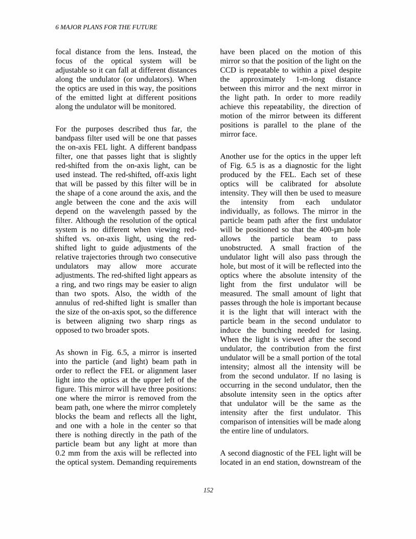
6 MAJOR PLANS FOR THE FUTURE
152
focal distance from the lens. Instead, thefocus of the optical system will beadjustable so it can fall at different distancesalong the undulator (or undulators). Whenthe optics are used in this way, the positionsof the emitted light at different positionsalong the undulator will be monitored.
For the purposes described thus far, thebandpass filter used will be one that passesthe on-axis FEL light. A different bandpassfilter, one that passes light that is slightlyred-shifted from the on-axis light, can beused instead. The red-shifted, off-axis lightthat will be passed by this filter will be inthe shape of a cone around the axis, and theangle between the cone and the axis willdepend on the wavelength passed by thefilter. Although the resolution of the opticalsystem is no different when viewing red-shifted vs. on-axis light, using the red-shifted light to guide adjustments of therelative trajectories through two consecutiveundulators may allow more accurateadjustments. The red-shifted light appears asa ring, and two rings may be easier to alignthan two spots. Also, the width of theannulus of red-shifted light is smaller thanthe size of the on-axis spot, so the differenceis between aligning two sharp rings asopposed to two broader spots.
As shown in Fig. 6.5, a mirror is insertedinto the particle (and light) beam path inorder to reflect the FEL or alignment laserlight into the optics at the upper left of thefigure. This mirror will have three positions:one where the mirror is removed from thebeam path, one where the mirror completelyblocks the beam and reflects all the light,and one with a hole in the center so thatthere is nothing directly in the path of theparticle beam but any light at more than0.2 mm from the axis will be reflected intothe optical system. Demanding requirements
have been placed on the motion of thismirror so that the position of the light on theCCD is repeatable to within a pixel despitethe approximately 1-m-long distancebetween this mirror and the next mirror inthe light path. In order to more readilyachieve this repeatability, the direction ofmotion of the mirror between its differentpositions is parallel to the plane of themirror face.
Another use for the optics in the upper leftof Fig. 6.5 is as a diagnostic for the lightproduced by the FEL. Each set of theseoptics will be calibrated for absoluteintensity. They will then be used to measurethe intensity from each undulatorindividually, as follows. The mirror in theparticle beam path after the first undulatorwill be positioned so that the 400-µm holeallows the particle beam to passunobstructed. A small fraction of theundulator light will also pass through thehole, but most of it will be reflected into theoptics where the absolute intensity of thelight from the first undulator will bemeasured. The small amount of light thatpasses through the hole is important becauseit is the light that will interact with theparticle beam in the second undulator toinduce the bunching needed for lasing.When the light is viewed after the secondundulator, the contribution from the firstundulator will be a small portion of the totalintensity; almost all the intensity will befrom the second undulator. If no lasing isoccurring in the second undulator, then theabsolute intensity seen in the optics afterthat undulator will be the same as theintensity after the first undulator. Thiscomparison of intensities will be made alongthe entire line of undulators.
A second diagnostic of the FEL light will belocated in an end station, downstream of the
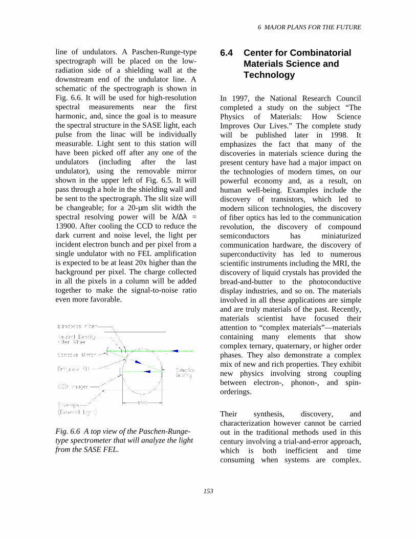
6 MAJOR PLANS FOR THE FUTURE
153
line of undulators. A Paschen-Runge-typespectrograph will be placed on the low-radiation side of a shielding wall at thedownstream end of the undulator line. Aschematic of the spectrograph is shown inFig. 6.6. It will be used for high-resolutionspectral measurements near the firstharmonic, and, since the goal is to measurethe spectral structure in the SASE light, eachpulse from the linac will be individuallymeasurable. Light sent to this station willhave been picked off after any one of theundulators (including after the lastundulator), using the removable mirrorshown in the upper left of Fig. 6.5. It willpass through a hole in the shielding wall andbe sent to the spectrograph. The slit size willbe changeable; for a 20-µm slit width thespectral resolving power will be λ/∆λ =13900. After cooling the CCD to reduce thedark current and noise level, the light perincident electron bunch and per pixel from asingle undulator with no FEL amplificationis expected to be at least 20x higher than thebackground per pixel. The charge collectedin all the pixels in a column will be addedtogether to make the signal-to-noise ratioeven more favorable.
Fig. 6.6 A top view of the Paschen-Runge-type spectrometer that will analyze the lightfrom the SASE FEL.
6.4 Center for CombinatorialMaterials Science andTechnology
In 1997, the National Research Councilcompleted a study on the subject “ThePhysics of Materials: How ScienceImproves Our Lives.” The complete studywill be published later in 1998. Itemphasizes the fact that many of thediscoveries in materials science during thepresent century have had a major impact onthe technologies of modern times, on ourpowerful economy and, as a result, onhuman well-being. Examples include thediscovery of transistors, which led tomodern silicon technologies, the discoveryof fiber optics has led to the communicationrevolution, the discovery of compoundsemiconductors has miniaturizedcommunication hardware, the discovery ofsuperconductivity has led to numerousscientific instruments including the MRI, thediscovery of liquid crystals has provided thebread-and-butter to the photoconductivedisplay industries, and so on. The materialsinvolved in all these applications are simpleand are truly materials of the past. Recently,materials scientist have focused theirattention to “complex materials”—materialscontaining many elements that showcomplex ternary, quaternary, or higher orderphases. They also demonstrate a complexmix of new and rich properties. They exhibitnew physics involving strong couplingbetween electron-, phonon-, and spin-orderings.
Their synthesis, discovery, andcharacterization however cannot be carriedout in the traditional methods used in thiscentury involving a trial-and-error approach,which is both inefficient and timeconsuming when systems are complex.
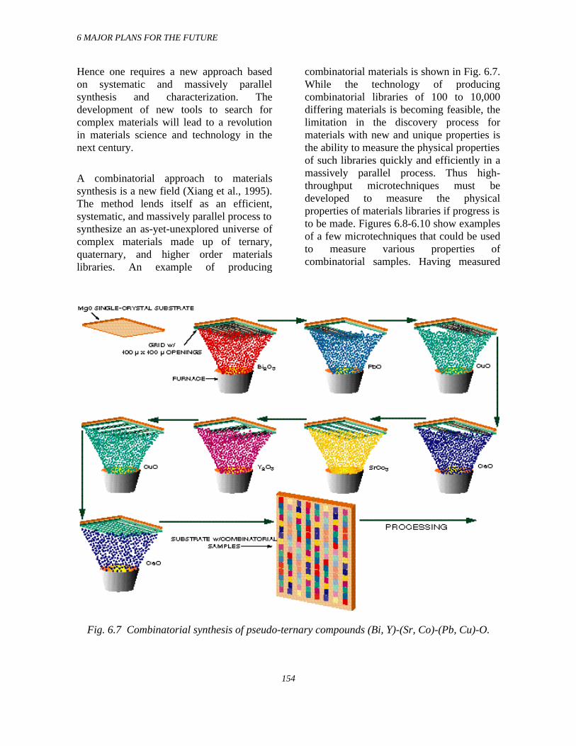
6 MAJOR PLANS FOR THE FUTURE
154
Hence one requires a new approach basedon systematic and massively parallelsynthesis and characterization. Thedevelopment of new tools to search forcomplex materials will lead to a revolutionin materials science and technology in thenext century.
A combinatorial approach to materialssynthesis is a new field (Xiang et al., 1995).The method lends itself as an efficient,systematic, and massively parallel process tosynthesize an as-yet-unexplored universe ofcomplex materials made up of ternary,quaternary, and higher order materialslibraries. An example of producing
combinatorial materials is shown in Fig. 6.7.While the technology of producingcombinatorial libraries of 100 to 10,000differing materials is becoming feasible, thelimitation in the discovery process formaterials with new and unique properties isthe ability to measure the physical propertiesof such libraries quickly and efficiently in amassively parallel process. Thus high-throughput microtechniques must bedeveloped to measure the physicalproperties of materials libraries if progress isto be made. Figures 6.8-6.10 show examplesof a few microtechniques that could be usedto measure various properties ofcombinatorial samples. Having measured
Fig. 6.7 Combinatorial synthesis of pseudo-ternary compounds (Bi, Y)-(Sr, Co)-(Pb, Cu)-O.
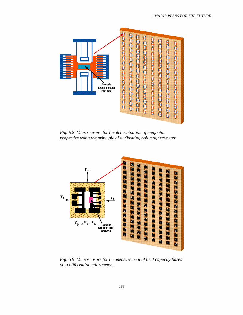
6 MAJOR PLANS FOR THE FUTURE
155
Fig. 6.8 Microsensors for the determination of magneticproperties using the principle of a vibrating coil magnetometer.
Fig. 6.9 Microsensors for the measurement of heat capacity basedon a differential calorimeter.
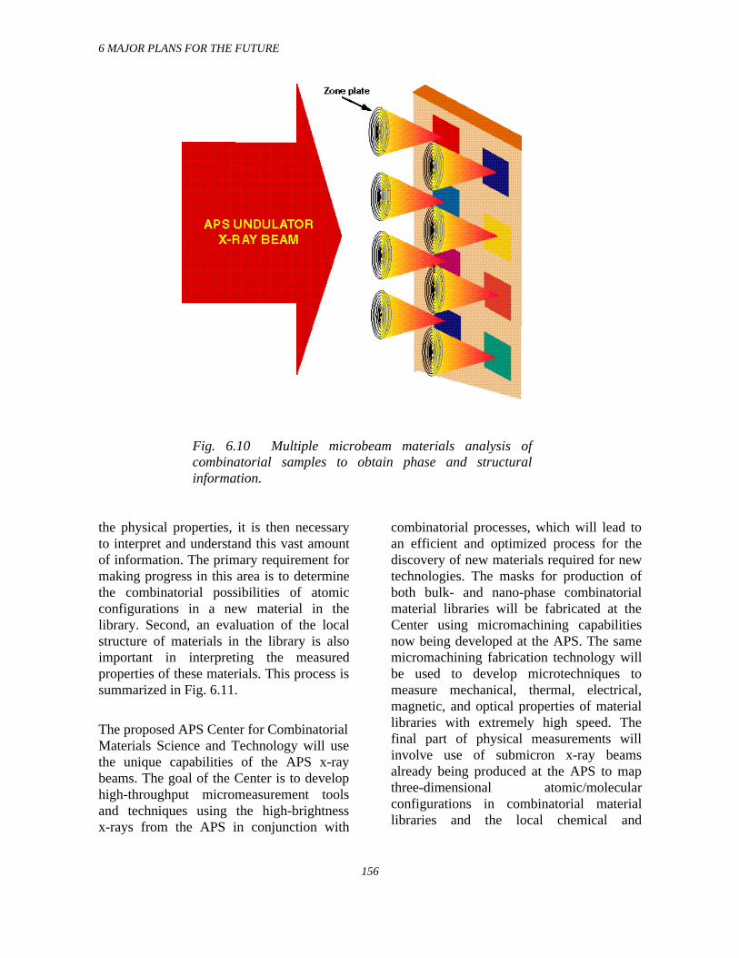
6 MAJOR PLANS FOR THE FUTURE
156
Fig. 6.10 Multiple microbeam materials analysis ofcombinatorial samples to obtain phase and structuralinformation.
the physical properties, it is then necessaryto interpret and understand this vast amountof information. The primary requirement formaking progress in this area is to determinethe combinatorial possibilities of atomicconfigurations in a new material in thelibrary. Second, an evaluation of the localstructure of materials in the library is alsoimportant in interpreting the measuredproperties of these materials. This process issummarized in Fig. 6.11.
The proposed APS Center for CombinatorialMaterials Science and Technology will usethe unique capabilities of the APS x-raybeams. The goal of the Center is to develophigh-throughput micromeasurement toolsand techniques using the high-brightnessx-rays from the APS in conjunction with
combinatorial processes, which will lead toan efficient and optimized process for thediscovery of new materials required for newtechnologies. The masks for production ofboth bulk- and nano-phase combinatorialmaterial libraries will be fabricated at theCenter using micromachining capabilitiesnow being developed at the APS. The samemicromachining fabrication technology willbe used to develop microtechniques tomeasure mechanical, thermal, electrical,magnetic, and optical properties of materiallibraries with extremely high speed. Thefinal part of physical measurements willinvolve use of submicron x-ray beamsalready being produced at the APS to mapthree-dimensional atomic/molecularconfigurations in combinatorial materiallibraries and the local chemical and
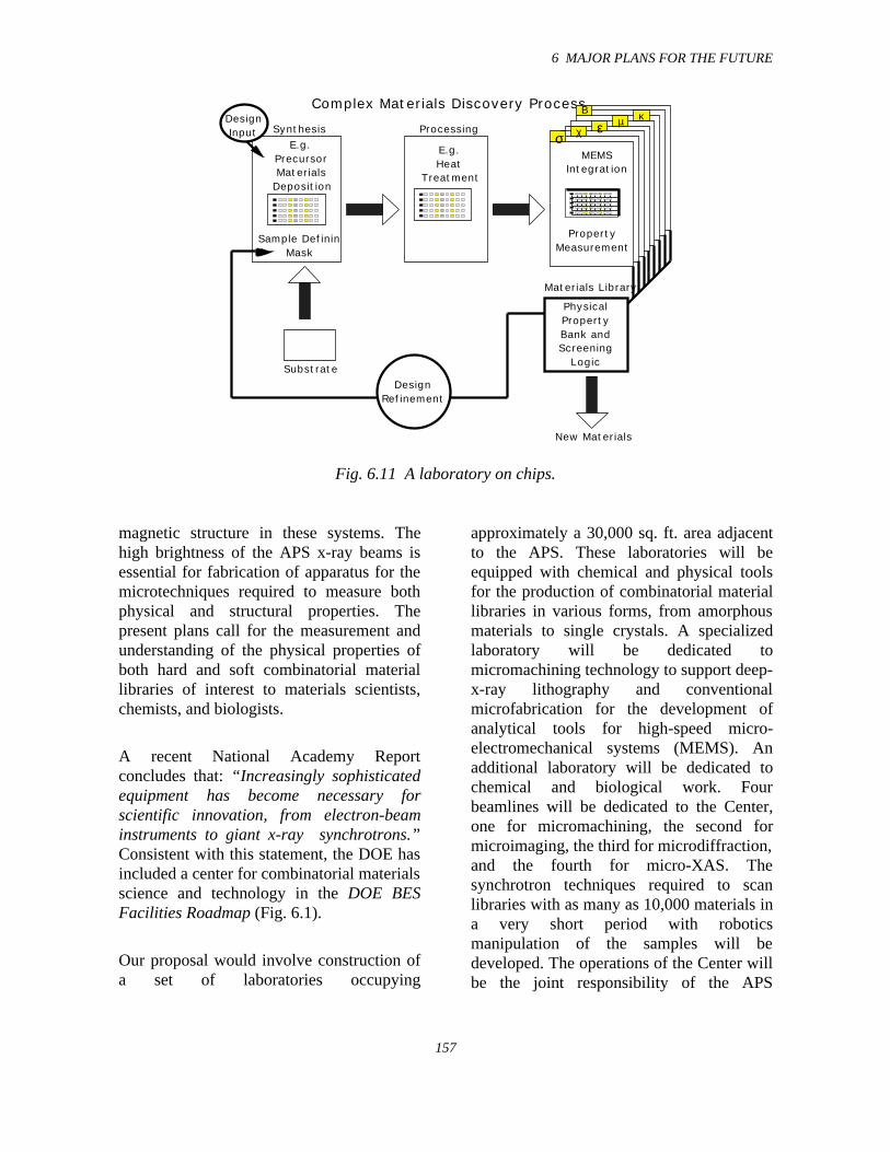
6 MAJOR PLANS FOR THE FUTURE
157
DesignInput
DesignRefinement
Physical PropertyBank andScreening
Logic
MEMS Integration
E.g.Heat
Treatment
E.g.Precursor MaterialsDeposition
Synthesis Processing
New Materials
Substrate
Sample Defining Mask
PropertyMeasurement
Complex Materials Discovery Process
σ εχ
µ κB
Materials Library
Fig. 6.11 A laboratory on chips.
magnetic structure in these systems. Thehigh brightness of the APS x-ray beams isessential for fabrication of apparatus for themicrotechniques required to measure bothphysical and structural properties. Thepresent plans call for the measurement andunderstanding of the physical properties ofboth hard and soft combinatorial materiallibraries of interest to materials scientists,chemists, and biologists.
A recent National Academy Reportconcludes that: “Increasingly sophisticatedequipment has become necessary forscientific innovation, from electron-beaminstruments to giant x-ray synchrotrons.”Consistent with this statement, the DOE hasincluded a center for combinatorial materialsscience and technology in the DOE BESFacilities Roadmap (Fig. 6.1).
Our proposal would involve construction ofa set of laboratories occupying
approximately a 30,000 sq. ft. area adjacentto the APS. These laboratories will beequipped with chemical and physical toolsfor the production of combinatorial materiallibraries in various forms, from amorphousmaterials to single crystals. A specializedlaboratory will be dedicated tomicromachining technology to support deep-x-ray lithography and conventionalmicrofabrication for the development ofanalytical tools for high-speed micro-electromechanical systems (MEMS). Anadditional laboratory will be dedicated tochemical and biological work. Fourbeamlines will be dedicated to the Center,one for micromachining, the second formicroimaging, the third for microdiffraction,and the fourth for micro-XAS. Thesynchrotron techniques required to scanlibraries with as many as 10,000 materials ina very short period with roboticsmanipulation of the samples will bedeveloped. The operations of the Center willbe the joint responsibility of the APS
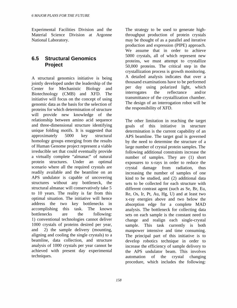
6 MAJOR PLANS FOR THE FUTURE
158
Experimental Facilities Division and theMaterial Science Division at ArgonneNational Laboratory.
6.5 Structural GenomicsProject
A structural genomics initiative is beingjointly developed under the leadership of theCenter for Mechanistic Biology andBiotechnology (CMB) and XFD. Theinitiative will focus on the concept of usinggenomic data as the basis for the selection ofproteins for which determination of structurewill provide new knowledge of therelationship between amino acid sequenceand three-dimensional structure identifyingunique folding motifs. It is suggested thatapproximately 5000 key structuralhomology groups emerging from the resultsof Human Genome project represent a viableirreducible set that could eventually providea virtually complete “almanac” of naturalprotein structures. Under an optimalscenario where all the required crystals arereadily available and the beamline on anAPS undulator is capable of uncoveringstructures without any bottleneck, thestructural almanac will conservatively take 5to 10 years. The reality is far from thisoptimal situation. The initiative will henceaddress the two key bottlenecks inaccomplishing this task. The knownbottlenecks are the following:1) conventional technologies cannot deliver1000 crystals of proteins desired per year,and 2) the sample delivery (mounting,aligning and cooling the single crystals) to abeamline, data collection, and structureanalysis of 1000 crystals per year cannot beachieved with present day experimentaltechniques.
The strategy to be used to generate high-throughput production of protein crystalsmay be thought of as a parallel and iterativeproduction and expression (PIPE) approach.We assume that in order to achieve5000 crystals, all of which represent newproteins, we must attempt to crystallize50,000 proteins. The critical step in thecrystallization process is growth monitoring.A detailed analysis indicates that over athousand examinations have to be performedper day using polarized light, whichinterrogates the reflectance and/ortransmittance of the crystallization chamber.The design of an interrogation robot will bethe responsibility of XFD.
The other limitation in reaching the targetgoals of this initiative in structuredetermination is the current capability of anAPS beamline. The target goal is governedby the need to determine the structure of alarge number of crystal protein samples. Thefollowing additional constraints increase thenumber of samples. They are (1) shortexposures to x-rays in order to reduce thecrystal damage from radiation, thusincreasing the number of samples of onekind to be studied, and (2) additional datasets to be collected for each structure withdifferent contrast agent (such as Se, Br, Eu,Re, Os, Ir, Pt, Au, Hg, U) and at least twox-ray energies above and two below theabsorption edge for a complete MADanalysis. The bottleneck for collecting datasets on each sample is the constant need tochange and realign each single-crystalsample. This task currently is bothmanpower intensive and time consuming.The principal part of this initiative is todevelop robotics technique in order toincrease the efficiency of sample delivery tothe APS undulator beam. This involvesautomation of the crystal changingprocedure, which includes the following:
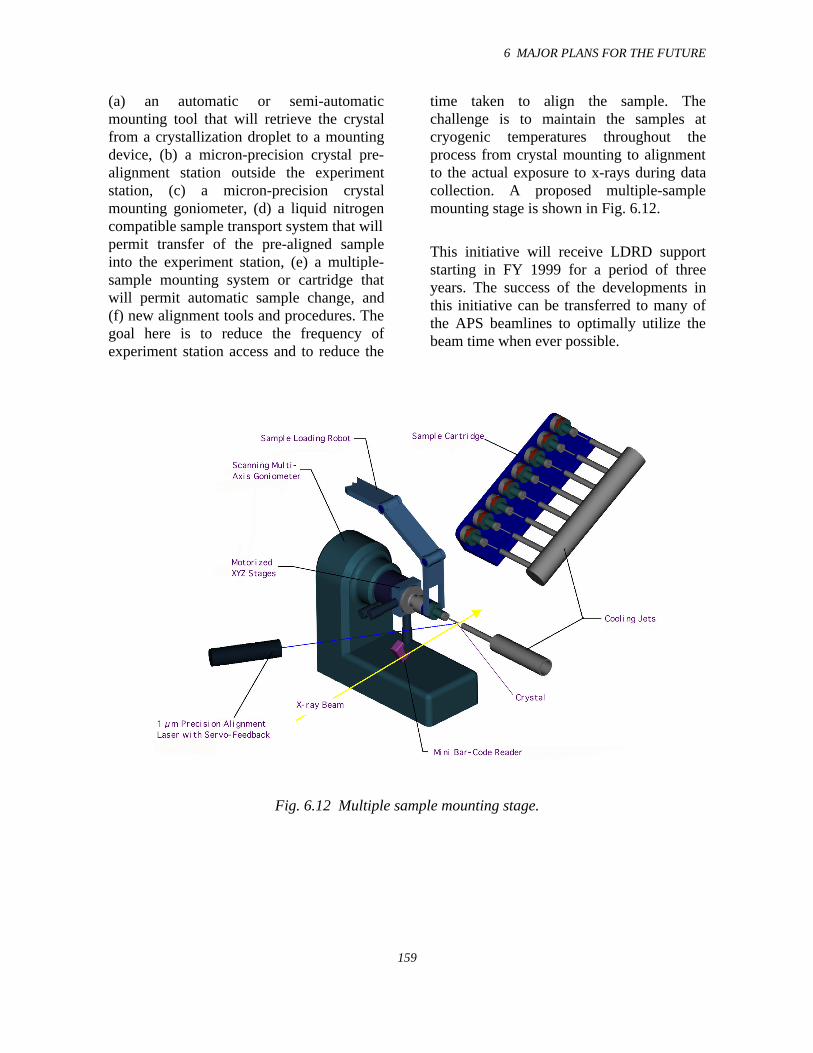
6 MAJOR PLANS FOR THE FUTURE
159
(a) an automatic or semi-automaticmounting tool that will retrieve the crystalfrom a crystallization droplet to a mountingdevice, (b) a micron-precision crystal pre-alignment station outside the experimentstation, (c) a micron-precision crystalmounting goniometer, (d) a liquid nitrogencompatible sample transport system that willpermit transfer of the pre-aligned sampleinto the experiment station, (e) a multiple-sample mounting system or cartridge thatwill permit automatic sample change, and(f) new alignment tools and procedures. Thegoal here is to reduce the frequency ofexperiment station access and to reduce the
time taken to align the sample. Thechallenge is to maintain the samples atcryogenic temperatures throughout theprocess from crystal mounting to alignmentto the actual exposure to x-rays during datacollection. A proposed multiple-samplemounting stage is shown in Fig. 6.12.
This initiative will receive LDRD supportstarting in FY 1999 for a period of threeyears. The success of the developments inthis initiative can be transferred to many ofthe APS beamlines to optimally utilize thebeam time when ever possible.
Fig. 6.12 Multiple sample mounting stage.
6 MAJOR PLANS FOR THE FUTURE
160
6.6 References
Dejus, R., and I. Vasserman (1998) ArgonneNational Laboratory, unpublished results.
Safranek, J., and P.M. Stefan (1996)Proceedings of EPAC ‘96, the FifthEuropean Particle Accelerator Conference,p. 1573.
Vinokurov, N. A. (1996) “The IntegralEquation for a High Gain FEL,” ArgonneNational Laboratory Report ANL/APS/TB-27.
Xiang, X.-D., et al.(1995) Science 268,1738.
APPENDIX 1
161
1997-1998 Publications by XFD Staff
Agamalian, M., J. M. Drake, S. K. Sinha, and J. D. Axe, “Neutron Diffraction Study ofthe Pore Surface Layer of Vycor Glass,” Phys. Rev. E 55 (1997) 3021-3027
Badyal, Y.S., M.-L. Saboungi, D.L. Price, D.R. Haeffner, and S.D. Shastri, "Atomic andElectronic Structure of Liquid Iron Trichloride," Europhys. Lett. 39 (1997) 19-24
Basdogan, I., T. J. Royston, J. Barraza, D. Shu, and T. M. Kuzay, "A Theoretical andExperimental Study of the Vibratory Behavior of a High-Precision OpticalPositioning Table," Proc. of DETC'97, 1997 ASME Design Engineering TechnicalConferences, DETC97/VIB-4215 (1997) 1-11
Basdogan, I., T. J. Royston, A. A. Shabana, J. Barraza, D. Shu, and T. M. Kuzay,"Analysis of High-Precision Optical Positioning Systems for Vibration Stability atthe Advanced Photon Source,” SPIE Vol. 3132 (1997) 47-55
Cai, Z., B. Lai, W. Yun, E. Gluskin, D. Legnini, P. Ilinski, E. Trakhtenberg, S. Xu, W.Rodrigues, H-R. Lee, “Beam Size Measurement of the Stored Electron Beam at theAPS Storage Ring Using Zone Plate Optics and Undulator Radiation,” AIP Conf.Proc. 417 (1997) 101
Experimental Facilities Division Progress Report 1996-97, Argonne National LaboratoryReport ANL/APS/TB-30 (April 1997)
Feng, Y. P., I. McNulty, Z. Xu, and E. Gluskin, “Signal-to-Noise Ratio of IntensityInterferometry Experiments with Highly Asymmetric X-ray Source,” ArgonneNational Laboratory Light Source Note LS-258 (1997)
Fernandez, P. B., T. Graber, W.-K. Lee, D. M. Mills, C. S. Rogers, and L. A. Assoufid,"Test of a High-Heat-Load Double-Crystal Diamond Monochromator at theAdvanced Photon Source," Nucl. Instrum. Meth. Phys. Res. A 400 (1997) 476-483
Fernandez, P. B., T. Graber, S. Krasnicki, W.-K. Lee, D. M. Mills, C. S. Rogers, and L.A. Assoufid, "Test Results of a Diamond Double-Crystal Diamond Monochromatorat the Advanced Photon Source," Synchrotron Radiation Instrumention: Tenth U.S.National Conference, ed. E. Fontes (American Institute of Physics, 1997) pp.89-94
Fultz, B., C. C. Ahn, E. E. Alp, W. Sturhahn, and T. S. Toellner, “Phonons inNanocrystalline 57Fe,” Phys. Rev. Lett. 79 (1997) 937-940
Fultz, B., T. A. Stephens, W. Sturhahn, T. S. Toellner, and E. E. Alp, “Local ChemicalEnvironments and the Phonon Partial Densities of States of 57Fe in 57Fe3Al,” Phys.Rev. Lett. 80 (1998) 3304-3307
APPENDIX 1
162
Graber, T., S. Krasnicki, P. B. Fernandez, D. M. Mills, Q.-Y. Tong, and U. M. Gösele,“Progress in Silicon-to-Silicon Direct Bonding and its Application to SynchrotronX-ray Optics,” SPIE Vol. 3151 (1997) 54-64
Hahn, U., H. Schulte-Schrepping, K. Balewski, J. R. Schneider, P. Ilinski, B. Lai, W.Yun, D. Legnini, E. Gluskin, “Measurements of Emittance and Absolute SpectralFlux of the PETRA Undulator at DESY Hamburg,” J. Synchrotron Rad. 4 (1997) 1
Hoffberg, M., R. Laird, F. Lenkzsus, C. Liu, B. Rodricks, and A. Gelbart, "TheDevelopment of a HIgh-Speed 100 fps CCD Camera," Nucl. Instrum. Meth. Phys.Res. A 392 (1997) 214-219
Ilinski, P.,”Undulator A Diagnostics at the Advanced Photon Source,” Argonne NationalLaboratory Report ANL/APS/TB-33 (1998)
Ilinski, P., C. T. Venkataraman, J. C. Lang, and G. Srajer, “Characterization of theElliptical Multipole Wiggler at the Advanced Photon Source,” SynchrotronRadiation Instrumention: Tenth U.S. National Conference, ed. E. Fontes (AmericanInstitute of Physics, 1997) pp.49-54
Ishimatsu, N., C. T. Venkataraman, H. Hashizume, N. Hosoito, K. Namikawa, and T.Iwazumi, “X-ray Reflectivity at the L Edges of Gd,” J. Synchrotron Rad. 4 (1997)175-179
Kushnir, V. I., P. M. Abbamonte, A. T. Macrander, and M. Schwoerer-Böhning,"Backscattering Channel-Cut High Resolution Monochromator for Inelastic X-rayScattering,” SPIE Vol. 3151 (1997) 324-328
Lal, J., S. K. Sinha, and L. Auvray, “Structure of Polymer Chains Confined in Vycor,” J.de Physique II 7 (1997) 1597
Lee, H.-R, "A Novel Iterative Optimizing Quantization Technique for Limited DataComputed Tomography,” Optical Engineering Monthly Journal, April 1997
Lee, H.-R., B. Lai, W. Yun, D. Mancini, Z. Cai, “X-Ray Microtomography as a FastThree-Dimensional Imaging Technology using a CCD Camera Coupled with aCdWO4 Single-Crystal Scintillator,” SPIE Vol. 3149 (1997) 257
Lee, H.-R., W. Yun, Z. Cai, W. Rodrigues, D. S. Kupperman, “X-ray MicrodiffractionStudies to Measure Strain Fields in a Metal Matrix Composite,” AIP Conf. Proc.417 (1997) 166
APPENDIX 1
163
Lee, W.-K., P. B. Fernandez, A. Khounsary, W. Yun, and E. Trakhtenberg, "AdvancedPhoton Source Undulator Beamline Tests of a Contact-Cooled Silicon U-ShapedMonochromator," SPIE Vol. 3151 (1997) 208-215
Liu, C., D. Shu, T. M. Kuzay, R. Wen, and C. A. Melendres, "Ion Beam Induced SurfaceModification of Chemical Vapor Deposition Diamond for X-ray Beam PositionMonitor Applications,” J. Vac. Sci. Technol. A 15 (1997) 1200-1205
Lynn, J. W., S. Skanthakumar, Q. Huang, S. K. Sinha, Z.Hossain, L. C. Gupta, R.Nagerajan, and C. Godart, “Magnetic Order and Crystal Structure in theSuperconducting RNi2B2C Materials,” Phys. Rev. B 55 (1997) 6584
Macrander, A. T., M. Schwoerer-Böhning, P. M. Abbamonte, and M. Hu, "HighResolution Monochromator for Inelastic Scattering Studies of High EnergyPhonons Using Undulator Radiation at the Advanced Photon Source," SPIE Vol.3151 (1997) 271-281
Makarov, O. A., P. Den Hartog, E. R. Moog, and M. L. Smith, “Control System forInsertion Devices at the Advanced Photon Source,” Synchrotron RadiationInstrumention: Tenth U.S. National Conference, ed. E. Fontes (American Instituteof Physics, 1997) pp.43-47
Mills, D. M., "X-ray Optics Developments at the APS for the Third Generation of High-Energy Synchrotron Radiation Sources," J. Synchrotron Rad. 4 (1997) 117-124
Mochrie, S. G. J., A. M. Mayes, A. R. Sandy, M. Sutton, S. Brauer, G. B. Stephenson, D.L. Abernathy, and G. Grubel, “Dynamics of Block Copolymer Micelles Revealedby X-ray Intensity Fluctuation Spectroscopy,” Phys. Rev. Lett. 78 (1997) 1275-1278
Moog, E. R., P. K. Den Hartog, E. J. Semones, and P. K. Job, “Radiation Doses toInsertion Devices at the Advanced Photon Source,” Synchrotron RadiationInstrumention: Tenth U.S. National Conference, ed. E. Fontes (American Instituteof Physics, 1997) pp. 219-223
Mui, P. H., G. Srajer, and D. M. Mills, "In-situ Surface Monitoring System forSynchrotron Mirrors under High Heat Load," Applied Optics 36 (1997) 5546-5551
Ocko, B. M., X. Z. Wu, E. B. Sirota, S. K. Sinha, O. Gang, and M. Deutsch, “SurfaceFreezing in Chain Molecules: I. Normal Alkanes,” Phys. Rev. E 55 (1997) 3164
Pisharody, M., P. K. Job, S. Magill, J. Proudfoot, and R. Stanek, "Measurement of GasBremsstrahlung from Electron Storage Rings," Nucl. Instrum. Meth. Phys. Res. A401 (1997) 442-462
APPENDIX 1
164
Pisharody, M., P. K. Job, S. Magill, J. Proudfoot, and R. Stanek, “Measurement of GasBremsstrahlung from the Insertion Device Beamlines of the Advanced PhotonSource,” Argonne National Laboratory Light Source Note LS-260 (1997)
Pisharody, M., E. Semones, and P. K. Job, “Dose Measurements of Bremsstrahlung-Produced Neutrons at the Advanced Photon Source,” Argonne National LaboratoryLight Source Note LS-269 (1998)
Pisharody, M., P. K. Job, S. Magill, J. Proudfoot, and R. Stanek, “Measurement of GasBremsstrahlung from the Insertion Device Beam Lines of the Advanced PhotonSource,” Proceedings of the Third Specialists Meeting on Shielding Aspects ofAccelerators, Targets and Irradiation Facilities (Nuclear Energy Agency, OECDPublications, Paris, France, 1998) pp. 33-40
Randall, K. J., Z. Xu, J. F. Moore, and E. Gluskin, “Soft X-ray Spectroscopy UndulatorBeamline at the Advanced Photon Source,” SPIE Vol. 3150 (1997) 189-194
Rodrigues, W., Z. Cai, W. Yun, H-R. Lee, P. Ilinski, E. Isaacs, J. Grenko, “X-rayMicrodiffraction Studies of an Integrated Laser-Modulator System,” AIP Conf.Proc. 417 (1997) 161
Röhlsberger, R., E. Gerdau, R. Rüffer, W. Sturhahn, T. S. Toellner, A. I. Chumakov, andE. E. Alp, “X-ray Optics for µeV-Resolved Spectroscopy,” Nucl. Instrum. Meth.Phys. Res. A 394 (1997) 251-255
Rosenkranz, S., R. Osborn, J. F. Mitchell, L. Vasiliu-Doloc, J.W. Lynn, S. K. Sinha, andD. N. Argyriou, "Magnetic Correlations in the Bilayer ManganiteLa1,2Sr1.8Mn2O7," J. Appl. Phys. 83 (1998) 7348
Sanchez del Rio, M., and R. J. Dejus, "XOP: A Multiplatform Graphical User Interfacefor Synchrotron Radiation Spectral and Optics Calculations,” SPIE Vol. 3152(1997) 148-157
Schwoerer-Böhning, M., P. M. Abbamonte, A. T. Macrander, and V. I. Kushnir, "ASpherical Bent Focusing Analyzer for High Resolution Inelastic X-ray Scattering,"SPIE Vol. 3151 (1997) 282-286
Schwoerer-Böhning, M., A. T. Macrander, and D. A. Arms, “Phonon Dispersion ofDiamond Measured by Inelastic X-ray Scattering,” Phys. Rev. Lett. 80 (1998)5572-5575
Schwoerer-Böhning, M., A. T. Macrander, P. M. Abbamonte, , and D. A. Arms, “HighResolution Inelastic X-ray Scattering Spectrometer at the Advanced PhotonSource,” Rev. Sci. Instrum. 69 (1998) 3109-3112
APPENDIX 1
165
Shastri, S.D, R. J. Dejus, and D. R. Haeffner, "Experimental Characterization of APSUndulator A at High Photon Energies (50-200 keV)," J. Synchrotron Rad. 5 (1998)67-71
Shu, D., C. Benson, J. Chang, J. Barraza, T. M. Kuzay, E. E. Alp, W. Sturhahn, B. Lai, I.McNulty, K. Randall, G. Srajer, Z. Xu, and W. Yun, “Mirror Mounts Designed forthe Advanced Photon Source SRI-CAT,” Synchrotron Radiation Instrumention:Tenth U.S. National Conference, ed. E. Fontes (American Institute of Physics,1997) pp.179-185
Sinha, S. K., and R. Pynn, “Diffuse X-ray and Neutron Reflection from Surfaces andInterfaces,” in Local Structure from Diffraction, eds. S. J. L. Billinge and M. F.Thorpe (Plenum Press, New York, 1998)
Sinha, S. K., M. Tolan, and A. Gibaud, “Effects of Partial Coherence on the Scattering ofX-rays by Matter,” Phys. Rev. B 57 (1998) 2740-2758
Smither, R. K., A. M. Khounsary, and S. Xu, "Potential of a Beryllium X-ray Lens,"SPIE Vol. 3151 (1997) 150-163
Sutter, J., E. Alp, J. Barraza, and D. Shu, “Vibrational Measurements in 3-ID-B,”Argonne National Laboratory Light Source Note LS-265 (1998)
Toellner, T. S., M. Y. Hu, W. Sturhahn, K. Quast, and E. E. Alp, "Inelastic NuclearResonant Scattering with Sub-meV Energy Resolution," Applied Physics Letters 71(1997) 2112-2114
Tolan, M., and S. K. Sinha, "X-ray Scattering with Partially Coherent Radiation: TheExact Relationship between Resolution and Coherence," Physica B 248 (1998) 399
Tolan, M., O. H. Seeck, J.-P Schlomka, W. Press, J. Wang, S. K. Sinha, Z. Li, M.Rafailovich, and J. Sokolov, "Evidence for Capillary Waves on Dewetted PolymerFilm Surfaces: A Combined X-ray and Atomic Force Microscopy Study," Phys.Rev. Lett. 81 (1998) 2731
Ulmer, M., R. Altkorn, A. Krieger, D. Parsignault, Y. Chung, M. Wong, B. Lai, D.Mancini, P. Takacs, E. Church, “Super Mirror Fabrication via Electroforming,”SPIE Vol. 3153 (1997) 240
Vasserman, I., “Test of Horizontal Field Measurements Using Two-Axis Hall Probes atthe APS Magnetic Measurement Facility,” Argonne National Laboratory ReportANL/APS/TB-32 (1998)
Venkataraman, C. T., J. C. Lang, C. S. Nelson, G. Srajer, D. R. Haeffner, and S. D.Shastri, “A High Energy Phase Retarder for the Simultaneous Production of Right-
APPENDIX 1
166
and Left-Handed Circularly Polarized X-rays,” Rev. Sci. Instrum. 69 (1998) 1970-1973
Vignaud, G., A. Gibaud, J. Wang, S. K. Sinha, J. Daillant, G. Grubel, and Y. Gallot, “AnX-ray Scattering Study of Laterally Modulated Structures: The Example of DiblockCopolymers,” J. Phys.: Condens. Matter 9 (1997) L125
Vinokurov, N. A., R. J. Dejus, H. Friedsam, E. S. Gluskin, J. Maines, S. V. Milton, E. R.Moog, E. M. Trakhtenberg, and I. B. Vasserman, “Design Considerations for theMagnetic System of a Prototype X-ray Free Electron Laser,” SPIE Vol. 2988(1997) 64-68
Wang, J., A. K. Sood, P. V. Satyam, Y. Feng, X.-Z. Wu, Z. Cai, W. Yun, and S. K.Sinha, “X-ray Fluorescence Correlation Spectroscopy: A Method for StudyingParticle Dynamics in Condensed Matter,” Phys. Rev. Lett. 80 (1998) 1110-1113
Wang, J., “Characterizing Surfaces and Interfaces Using X-ray Standing Waves,” Invitedpaper to be published in Current Opinion in Colloid and Interface Science, Vol.3/3, 1998
Xu, Z. and K. J. Randall, “Virtual Sine Arm Kinematic Mount System,” SPIE Vol.3150(1997) 183-188
Zhao, M., D. S. Dmitriy, Z. Cai, and S. A. Rice, "Structure of Liquid Ga and the Liquid-Vapor Interface of Ga, Phys. Rev. E 56 (1997) 7033-7042
Patent Application
Bajiakar, S. S., Francesco De Carlo, Joshua J. Song, “Enhanced adhesion for LIGAmicrofabrication by using a buffer layer,” Department of Energy Patent ApplicationNumber S-89, 870, May 1998
APPENDIX 2
167
1997-1998 Invited Presentations by XFD Staff
Alp, E. E., American Physical Society, March Meeting, March 17-21,1997, Kansas City, MO
Alp, E. E., Eighth Users Meeting for the Advanced Photon Source, April 15-17,1997, ArgonneNational Laboratory, IL
Alp, E. E., Crystallographic Applications of Synchrotron Radiation, July 31-August 1,1997,KEK-Tsukuba, Japan
Alp, E. E., Inelastic Scattering Probes of Condensed Matter, University of Chicago, May 13-15,1998, Chicago, IL
Alp, E. E., Free Electron Laser Workshop, Argonne National Laboratory, IL
Alp, E. E., SPIE, Time Resolved Studies Symposium July 20-24, 1998, San Diego, CA
Alp, E. E., HFI-11, International Conference on Hyperfine Interactions, Aug 24-28,1998,Durban, South Africa
Alp, E. E., International Workshop on Inelastic X-ray Scattering, October 19-21, 1998, Montauk,NY
Alp, E. E., 2nd International Conference on Synchrotron Radiation in Material Science, October31-November 3,1998, Kobe, Japan
Cai, Z., Studies of Strain Field in EML Devices and Electromigration in Thin Al/Cu ConductWires Using an X-ray Microscope, Scanning 98 (Tenth Annual International Meeting onScanning Microscopies), May 11, 1998, Baltimore, MD
Fernandez, P.B., Test Results of a Diamond Double-Crystal Monochromator at the AdvancedPhoton Source, Synchrotron Radiation Instrumentation: Tenth US National Conference,Cornell University, Ithaca, NY (1997)
Lai, B., Capabilities and Applications of an Advanced Scanning X-ray Microprobe, Scanning 98(Tenth Annual International Meeting on Scanning Microscopies), May 11, 1998,Baltimore, MD
Lai, B., Capabilities of X-ray Microprobe at the Advanced Photon Source, Principal ResidualStress Workshop, July 28, 1997, Los Alamos National Laboratory, NM
Moog, L., Magnetic Performance of Insertion Devices at the Advanced Photon Source, ParticleAccelerator Conference (PAC 97), May 12-165, 1997, Vancouver, Canada
APPENDIX 2
168
Moog, L., Insertion Devices at the Advanced Photon Source, November 1997 monthly meetingof the Joint Chicago Chapter of the IEEE Nuclear and Plasma Sciences Society and theIEEE Magnetics Society, Nov. 1997, Chicago, IL
Mooney, T., Overview of EPICS-based Beamline Software, New Opportunities forBetter UserGroup Software (NOBUGS '97), Dec. 10-12, 1997, Argonne National Laboratory
Shenoy, G. K., 7-GeV Advanced Photon Source, Fermi National Accelerator Laboratory, Sept24, 1997, Batavia, IL
Shenoy, G. K., 7-GeV Advanced Photon Source, Ceramic Society, June 25, 1998, ArgonneNational Laboratory
Shenoy, G. K., Possible Application of the APS to the Rotating Equipment Industry, RotatingEquipment Consortium, Sept. 30, 1998, Argonne National Laboratory
Shu, D., a series of 20 lectures on synchrotron radiation beamline design topics at the BeijingSynchrotron Radiation Facility (BSRF), Institute of High Energy Physics (IHEP), ChineseAcademy of Sciences, May 8-12, 1998, Beijing, China
Shu, D., APS Synchrotron Radiation Beamline Front-End Design, Shanghai Institute for NuclearResearch, Chinese Academy of Sciences, May 13, 1998, Shanghai, China
Sinha, S., X-Ray Studies of Surface Phase Transitions, Penn State U. Physics Colloquium, May7, 1997,
Sinha, S., Review of Condensed Matter Studies Using Synchrotron Radiation, (Birgeneau Panel)BESAC Sub-Committee on X-Ray Sources, May 10, 1997
Sinha, S., X-Ray Scattering from Condensed Matter Using Coherent Beams, 5th InternationalConference onSurface X-Ray and Neutron Scattering, July 18, 1997, DaresburyLaboratory, U.K.
Sinha, S., Synchrotron Radiation Studies of the Structure and Dynamics of Complex Fluid Films,European Physical Society Meeting, August 26, 1997, Leuwen, Belgium
Sinha, S., X-Ray Fluorescent Correlation Spectroscopy - a New Method of Studying SlowDynamics, XFEL Workshop, October 28, 1997, APS, Argonne National Laboratory
Sinha, S., The Use of Coherent, Partially Coherent and Incoherent Radiation to StudyFluctuations In Condensed Matter, SR-50 Meeting (Highlights of Synchrotron RadiationResearch), November 18, 1997
Sinha, S., The Use of Partially Coherent Radiation to Study Condensed Matter, PurdueUniversity, Physics Colloquium, Feb. 12, 1998, Lafayette, IN
APPENDIX 2
169
Sinha, S., Frontiers of Materials Science using Synchrotron Radiation, Johns Hopkins UniversityPhysics Colloquium, Mar. 26, 1998, Baltimore, MD
Sinha, S., Condensed Matter Studies using Coherent and Microfocused X-ray Beams, Universityof Wisconsin Physics Colloquium, April 3, 1998, Milwaukee, WI
Sinha, S., X-ray Diffuse Scattering as a Probe for the Study of Structural and MagneticRoughness in Metallic Multilayers, 3rd International Symposium on Metallic Multilayers,June 14-19, 1998, Vancouver, BC
Sinha, S., Synchrotron Radiation Studies of Liquid Polymer Films, American CrystallographicAssociation, July 18-23, 1998, Arlington, VA
Sinha, S., Neutron X-ray Scattering from Porous Media Fractals and Rough Surfaces, 6th
International Summer School on Neutron Scattering, Aug. 8-14, 1998, Zuoz, Switzerland
Sinha, S., New Developments in the Application of Synchrotron Radiation to Materials Science,Plenary Lecture SRMS-2 Conference, Oct. 31-Nov. 3, 1998, Kobe, Japan
Srajer, G., Magnetic Reflectivity Measurements in Fe/Gd Multilayers, Conference on “X-rays inMagnetism,” July 1998, Daresbury Laboratory, U.K.
Sturhahn, W., Inelastic Nuclear Resonant Scattering: Technique and Data Evaluation, Workshopon Inelastic Nuclear Resonant Scattering, April 21 - 22, 1997, Argonne NationalLaboratory
Sturhahn, W., Inelastic Nuclear Resonant Scattering, Gordon Conference on X-ray Physics,August 3-8, 1997, Plymouth, NH
Sturhahn, W., Introduction to Nuclear Resonant Scattering with Synchrotron Radiation,International Conference on the Applications of the Mossbauer Effect, Sept. 14 - 20, 1997,Rio de Janeiro, Brazil,
Sturhahn, W., Vibrational Dynamics of Thin Films by Inelastic Nuclear Resonant Scattering ofSynchrotron Radiation, International Conference on the Physics of X-ray MultilayerStructures, Mar. 1 - 5, 1998, Breckenridge, CO
Sturhahn, W., Vibrational Density of States Obtained from Inelastic Nuclear ResonantAbsorption of Synchrotron Radiation, Ninth International Conference on PhononScattering in Condensed Matter, July 26-31, 1998, Lancaster, U.K.
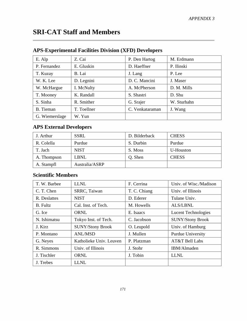
APPENDIX 3
171
SRI-CAT Staff and Members
APS-Experimental Facilities Division (XFD) Developers
E. Alp Z. Cai P. Den Hartog M. Erdmann
P. Fernandez E. Gluskin D. Haeffner P. Ilinski
T. Kuzay B. Lai J. Lang P. Lee
W. K. Lee D. Legnini D. C. Mancini J. Maser
W. McHargue I. McNulty A. McPherson D. M. Mills
T. Mooney K. Randall S. Shastri D. Shu
S. Sinha R. Smither G. Srajer W. Sturhahn
B. Tieman T. Toellner C. Venkataraman J. Wang
G. Wiemerslage W. Yun
APS External Developers
J. Arthur SSRL D. Bilderback CHESS
R. Colella Purdue S. Durbin Purdue
T. Jach NIST S. Moss U-Houston
A. Thompson LBNL Q. Shen CHESS
A. Stampfl Australia/ASRP
Scientific Members
T. W. Barbee LLNL F. Cerrina Univ. of Wisc./Madison
C. T. Chen SRRC, Taiwan T. C. Chiang Univ. of Illinois
R. Deslattes NIST D. Ederer Tulane Univ.
B. Fultz Cal. Inst. of Tech. M. Howells ALS/LBNL
G. Ice ORNL E. Isaacs Lucent Technologies
N. Ishimatsu Tokyo Inst. of Tech. C. Jacobson SUNY/Stony Brook
J. Kirz SUNY/Stony Brook O. Leupold Univ. of Hamburg
P. Montano ANL/MSD J. Mullen Purdue University
G. Neyes Katholieke Univ. Leuven P. Platzman AT&T Bell Labs
R. Simmons Univ. of Illinois J. Stohr IBM/Almaden
J. Tischler ORNL J. Tobin LLNL
J. Trebes LLNL
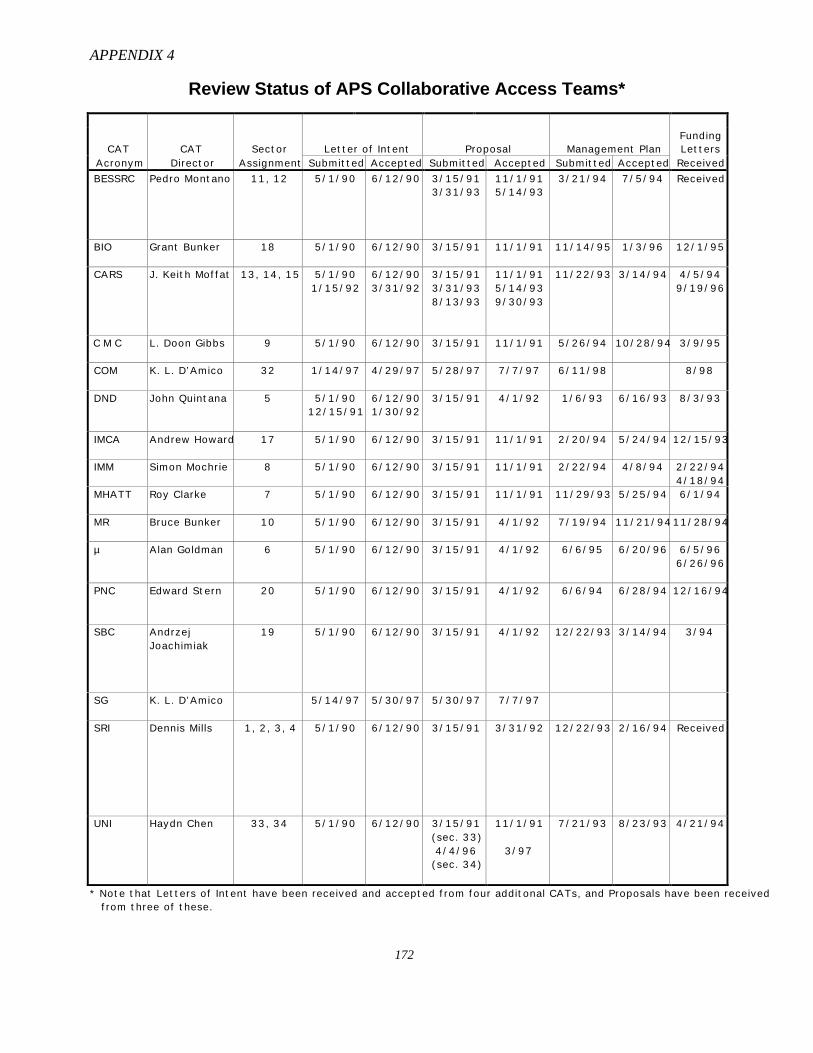
APPENDIX 4
172
Review Status of APS Collaborative Access Teams*
CAT CAT Sector Letter of Intent Proposal Management PlanFundingLetters
Acronym Director Assignment Submitted Accepted Submitted Accepted Submitted Accepted Received
BESSRC Pedro Montano 11, 12 5/1/90 6/12/90 3/15/913/31/93
11/1/915/14/93
3/21/94 7/5/94 Received
BIO Grant Bunker 18 5/1/90 6/12/90 3/15/91 11/1/91 11/14/95 1/3/96 12/1/95
CARS J. Keith Moffat 13, 14, 15 5/1/901/15/92
6/12/903/31/92
3/15/913/31/938/13/93
11/1/915/14/939/30/93
11/22/93 3/14/94 4/5/949/19/96
C M C L. Doon Gibbs 9 5/1/90 6/12/90 3/15/91 11/1/91 5/26/94 10/28/94 3/9/95
COM K. L. D’Amico 32 1/14/97 4/29/97 5/28/97 7/7/97 6/11/98 8/98
DND John Quintana 5 5/1/9012/15/91
6/12/901/30/92
3/15/91 4/1/92 1/6/93 6/16/93 8/3/93
IMCA Andrew Howard 17 5/1/90 6/12/90 3/15/91 11/1/91 2/20/94 5/24/94 12/15/93
IMM Simon Mochrie 8 5/1/90 6/12/90 3/15/91 11/1/91 2/22/94 4/8/94 2/22/944/18/94
MHATT Roy Clarke 7 5/1/90 6/12/90 3/15/91 11/1/91 11/29/93 5/25/94 6/1/94
MR Bruce Bunker 10 5/1/90 6/12/90 3/15/91 4/1/92 7/19/94 11/21/9411/28/94
µ Alan Goldman 6 5/1/90 6/12/90 3/15/91 4/1/92 6/6/95 6/20/96 6/5/966/26/96
PNC Edward Stern 20 5/1/90 6/12/90 3/15/91 4/1/92 6/6/94 6/28/94 12/16/94
SBC AndrzejJoachimiak
19 5/1/90 6/12/90 3/15/91 4/1/92 12/22/93 3/14/94 3/94
SG K. L. D’Amico 5/14/97 5/30/97 5/30/97 7/7/97
SRI Dennis Mills 1, 2, 3, 4 5/1/90 6/12/90 3/15/91 3/31/92 12/22/93 2/16/94 Received
UNI Haydn Chen 33, 34 5/1/90 6/12/90 3/15/91(sec. 33)4/4/96(sec. 34)
11/1/91
3/97
7/21/93 8/23/93 4/21/94
* Note that Letters of Intent have been received and accepted from four additonal CATs, and Proposals have been receivedfrom three of these.
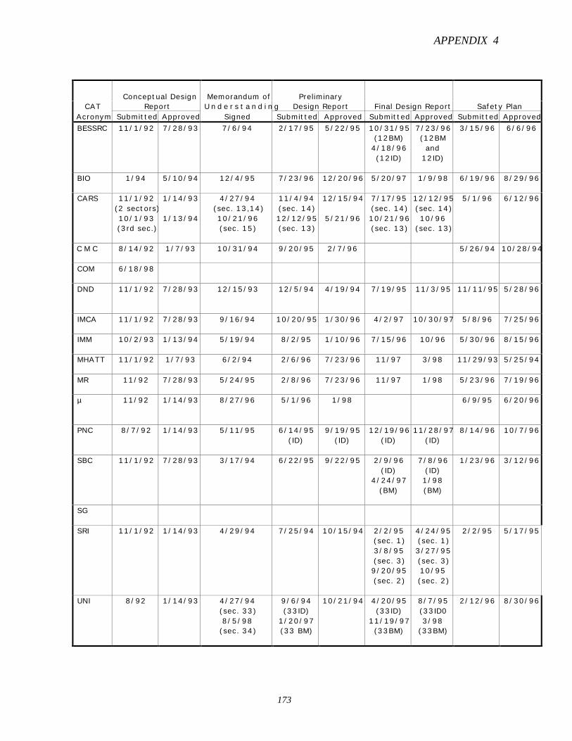
APPENDIX 4
173
Conceptual Design Memorandum of PreliminaryCAT Report U n d e r s t a n d i n g Design Report Final Design Report Safety Plan
Acronym Submitted Approved Signed Submitted Approved Submitted Approved Submitted Approved
BESSRC 11/1/92 7/28/93 7/6/94 2/17/95 5/22/95 10/31/95(12BM)4/18/96(12ID)
7/23/96(12BMand
12ID)
3/15/96 6/6/96
BIO 1/94 5/10/94 12/4/95 7/23/96 12/20/96 5/20/97 1/9/98 6/19/96 8/29/96
CARS 11/1/92(2 sectors)10/1/93(3rd sec.)
1/14/93
1/13/94
4/27/94(sec. 13,14)10/21/96(sec. 15)
11/4/94(sec. 14)12/12/95(sec. 13)
12/15/94
5/21/96
7/17/95(sec. 14)10/21/96(sec. 13)
12/12/95(sec. 14)10/96
(sec. 13)
5/1/96 6/12/96
C M C 8/14/92 1/7/93 10/31/94 9/20/95 2/7/96 5/26/94 10/28/94
COM 6/18/98
DND 11/1/92 7/28/93 12/15/93 12/5/94 4/19/94 7/19/95 11/3/95 11/11/95 5/28/96
IMCA 11/1/92 7/28/93 9/16/94 10/20/95 1/30/96 4/2/97 10/30/97 5/8/96 7/25/96
IMM 10/2/93 1/13/94 5/19/94 8/2/95 1/10/96 7/15/96 10/96 5/30/96 8/15/96
MHATT 11/1/92 1/7/93 6/2/94 2/6/96 7/23/96 11/97 3/98 11/29/93 5/25/94
MR 11/92 7/28/93 5/24/95 2/8/96 7/23/96 11/97 1/98 5/23/96 7/19/96
µ 11/92 1/14/93 8/27/96 5/1/96 1/98 6/9/95 6/20/96
PNC 8/7/92 1/14/93 5/11/95 6/14/95(ID)
9/19/95(ID)
12/19/96(ID)
11/28/97(ID)
8/14/96 10/7/96
SBC 11/1/92 7/28/93 3/17/94 6/22/95 9/22/95 2/9/96(ID)
4/24/97(BM)
7/8/96(ID)1/98(BM)
1/23/96 3/12/96
SG
SRI 11/1/92 1/14/93 4/29/94 7/25/94 10/15/94 2/2/95(sec. 1)3/8/95(sec. 3)9/20/95(sec. 2)
4/24/95(sec. 1)3/27/95(sec. 3)10/95(sec. 2)
2/2/95 5/17/95
UNI 8/92 1/14/93 4/27/94(sec. 33)8/5/98(sec. 34)
9/6/94(33ID)
1/20/97(33 BM)
10/21/94 4/20/95(33ID)
11/19/97(33BM)
8/7/95(33ID03/98
(33BM)
2/12/96 8/30/96

APPENDIX 5
174
User Agreement and Proprietary Account Status (8/25/98)
Listed below are the 143 institutions that have signed APS User Agreements as financially contributingCAT members (indicated by CAT acronyms) and/or as non-members (indicated by “II”) as of August 25,1998. A CAT Agreement covers users’ activities at that CAT’s beamlines; an II Agreement covers users’activities at any APS beamline. All listed Agreements are nonproprietary unless otherwise noted. Asuperscript p indicates that a proprietary User Account has also been established.
Abbott Laboratories (IMCA*,p, II)Adler Planetarium (II)Ames Lab (µ, II)Amoco (MR*,p)ANSTO (CARS, SRI)Bar-Ilan U. (II)Bayer Corp. (IMCA*)Bayerisches Geoinstitut (II)Bede Scientific (II)Bell Labs/div. of Lucent (MHATT, II)Biotechnology Research Inst. (II)Brandeis U. (II)Bristol-Myers Squibb (IMCA*,p)Brookhaven National Lab (CMC, II)California Inst. of Technol. (II)Carnegie Inst. of Washington/Geophys. Lab (II)Case Western Reserve U. (II)CINVESTAV-Merida (II)Columbia U. (II)Cornell U. (II)Daresbury Laboratory (II)DESY (II) (this Agreement covers HASYLAB)Digital Equipment Corp. (II)Dow (DND*,p)Duke University (II)DuPont (DND*,p)DuPont Merck (II*,p)Eli Lilly (IMCA*,p)Engineering & Mgmt. Specialists, Inc. (II*)ESRF (II)Exxon (CMC*)Field Museum (II)Florida State U. (II)Forschungszentrum Jülich (µ)Genentech, Inc. (II*)Georgia Inst. of Technol. (µ)Gerhard-Mercator-U. Duisburg/Laboratory of
Applied Physics (II)Glaxo (IMCA*,p)Goshen College (II)Harvard U. (II)Hebrew U. of Jerusalem (II)
Howard U. (MHATT)IBM (IMM, II)Illinois Inst. of Technol. (Bio, IMCA, MR, II)Indiana U. (II)Kent State U. (µ)Korea Electronics Technology Inst. (II)Kraft Foods Technol. Center (Bio*,p)Kyoto U. (II)Laboratoire de Minéralogie-Cristallographie Paris (II)Laboratoire Sciences de la Terre ENS Lyon (II)Lawrence Berkeley National Lab (II)Lawrence Livermore National Lab (II)Los Alamos National Lab (CMC, II)Louisiana State U. (II)Louisiana Tech. U./Inst. for Micromanufactg. (II)Massachusetts Inst. of Technol. (IMM)Max Planck Soc./Res. Unit for StructMolBiol.
(II)Mayo Foundation (II)McGill U. (IMM)Merck & Co., Inc. (IMCA*,p)Monsanto/Searle (IMCA*)Naval Research Lab (II)NCI-Frederick Cancer R&D Center (II)New Jersey Institute of Technology (II)NIST (SRI, UNI, II)North Carolina State U. (II)Northeastern U. (II)Northern Illinois U. (BESSRC, CARS)Northwestern U. (DND, MR, II)Oak Ridge Associated Universities (UNI)Oak Ridge National Lab (CMC, UNI, II)Ohio State U. (II)Pacific Northwest National Lab (PNC, II)Parke-Davis (IMCA*)Paul Scherrer Inst. (II)Pennsylvania State U. (II)Pharmacia & Upjohn (IMCA*,p)Photon Factory/KEK (II)Princeton U. (CMC, II)Procter & Gamble (IMCA*,p)Purdue Research Foundation (SRI)

APPENDIX 5
175
Purdue U. (II)Queens U. (IMM)Radiation Science, Inc. (II)Rensselaer Polytechnic Inst. (II)Rockefeller U. (II)Rutgers U. (II)St. Jude Children’s Research Hospital (II*)Schering-Plough Research Inst. (IMCA*,p)Scripps Research Inst. (II)Simon Fraser U. (PNC)SmithKline Beecham (IMCA*,p)Southern Illinois U. at Carbondale (CARS*, II*)Stanford U./SSRL (II)State U. of New York at Stony Brook (µ, II)Synchrotron Radiation Research Center (II)Technische Universität München (II)Tokyo Inst. of Technol. (II)Tokyo U. of Science (II)Tulane U. (II)U. de Marne la Vallée (II)U. College London Geological Sciences (II)U. of Alabama-Birmingham (II*)U. of California-Berkeley, Dept. of Geology and
Geophysics (II)U. of California-Irvine (II)U. of California-Santa Barbara (CMC, II)U. of Chicago (CARS, II)U. of Florida (MR, II)U. of Frankfurt (II)U. of Georgia (II)U. of Hamburg/Inst. für Experimentalphysik (II)
U. of Houston (II)U. of Illinois (UNI, II)U. of Kentucky (II)U. of Leuven (II)U. of Manchester (II)U. of Maryland (II)U. of Maryland Biotech Inst. (II)U. of Michigan (MHATT, II)U. of Minnesota (II)U. of Missouri-Columbia (µ, II)U. of Missouri-Kansas City (II)U. of New South Wales (II)U. of North Carolina (II)U. of Notre Dame (MR)U. of Paderborn (II)U. of Pennsylvania (CMC)U. of Rostock (II)U. of Tennessee (CMC, II)U. of Texas Southwestern Medical Center (II)U. of Vermont (II)U. of Vienna Inst. für Materialphysik (II)U. of Virginia/Dept. of Molec. Phys. (II)U. of Washington (PNC, II)U. of Western Ontario (II)U. of Wisconsin (µ, II)UOP (UNI*)Warsaw U. Poland (II)Washington U. (µ, II)Western Michigan U. (BESSRC, II)X-Ray Analytics, Ltd. (SBC, II)Yale U. (II)
*Both proprietary and nonproprietary Agreements have been signed.p A Proprietary User Account has been established.
APPENDIX 6
176
XFD Safety Report for FY 1998
1. Introduction
An important element of XFD’s mission is ensuring the safety of APS users, visitors, andAPS/XFD personnel, and the protection of the environment. In keeping with Integrated SafetyManagement (ISM) Core Function 5, “provide feedback and continuous improvement,” XFD isinitiating periodic reporting of its safety-related activities and statistics, beginning with thissummary for FY 1998.
2. Safety Training for XFD Personnel
Determining Training Requirements
The safety training requirements for most XFD personnel are determined by completing an ANLJob Hazard Questionnaire (JHQ). This document is used to identify the hazards employeesencounter on the job. Approximately once each year, employees and their supervisors jointlyreview the JHQ to ensure that it reflects the employees’ current assignments.
The data from completed JHQs are entered into ANL’s Training Management System (TMS), adatabase that uses the JHQ responses and Division input to identify each individual's trainingrequirements. The system produces a report, known as a Training Profile, that lists required andsuggested training, dates when training was completed, and dates by which training/retrainingmust be completed.
XFD supervisors and managers have real-time access to the records of those they supervisethorough a password-protected Web-based window into the TMS. This enables them to verify thatappropriate training is in place before assigning work. Employees also have access to their ownrecords.
Computer-Based and Web-Based Training
The following courses are available as computer-based training (CBT) administered by the XFDES&H Office:
• ESH738, General Employee Radiation Training
• ESH700, Radiological Worker Training – Level 1
• ESH702, Radiological Worker Training – Level 2
• ESH707, Accelerator Worker Radiation Safety
• DIV832, Chemical Hazards Training – Agents that Damage the Skin, MucousMembranes and Eyes
• DIV834, Chemical Hazards Training – Corrosives, Irritants, and Sensitizers
The following courses are available via the Web:
• ESH108/382, Building Safety Orientation
• ESH108/400/401, Building Safety Orientation
APPENDIX 6
177
• ESH223, Computer Protection
• ACIS/Tunnel Safety Courses
• Orientation for Chemical Management System Users (Nonmandatory)
Radiological Worker Training
All XFD personnel are required to complete ESH738, General Employee Radiation Training(GERT), and/or other courses from the following list as required by their work assignments:
• ESH700, Radiological Worker Training – Level 1
• ESH702, Radiological Worker Training – Level 2
• ESH707, Accelerator Worker Radiation Safety
• ESH709, Sealed Radioactive Source Custodian
• ESH713, Radiological Worker Training for X-ray Users
• APS457, APS Experimental Facilities Division X-Ray Laboratory Training
Most of these courses have both refresher and retraining requirements, which are met by attendingcourses with slightly different content and different course numbers.
Training Completed by XFD Personnel
To date, XFD personnel have attended more than 40 different safety courses and have collectivelycompleted approximately 2,935 hours of training
Training Compliance Progress
XFD’s compliance with training requirements, as calculated by TMS, has improved steadilythroughout FY 1998 to 98.7% as of October 5, 1998.
3. Safety Training for Users
The responsibility for APS user safety training is shared by the APS and the CATs. This trainingfalls into three broad categories:
“Core” training is required for all APS users and is administered by the APS User Office. As ofJuly 30, 1998, 1,070 APS users have completed the core training program, which consists of thefollowing elements:
APS User Orientation: This Web-based orientation, developed and updated as needed byXFD staff, is currently being delivered to newly arrived APS users via on-site computers;some preliminary experiments with remote delivery to users at their home institutions havebeen conducted. The general orientation course covers ANL and APS policies; generalsafety information such as site alarms, the use of 911, hazard communication, radiationsafety, and experiment safety; and the basics of the beamline Personnel Safety System(PSS). Additional safety information is provided by the APS User Guide and the pocket-
APPENDIX 6
178
sized APS User Safety Guide, both prepared by XFD staff; these booklets are part of theuser registration package and are also posted on the Web. All incoming users sign astatement confirming that they have read and understood both the APS User Guide and theUser Orientation and will follow the guidelines given there.
General Employee Radiation Training (GERT): The GERT training is a general APSrequirement consistent with DOE policy. APS users who do not have a current GERT cardfrom another DOE facility must pass a computer-based GERT exam. They may prepare forthe exam by taking a CBT course at the APS or via the Web, or by reading a hard-copystudy guide, which is part of the user registration package.
Sector-specific training is also required for all APS users; it is administered by the CATs. Tofacilitate this training, XFD has provided a model checklist of topics to be covered; each CAT maymodify the list as necessary. The training focuses on communicating specific information needed toimplement the CAT’s safety plan; examples include locations of utility shutoffs, chemical storagelocations and practices, and beamline-specific operation of the PSS. The CAT signs off on thechecklist and sends a copy to the APS User Office to verify that each new user who will beworking under its auspices has completed this training. To date, the User Office has receivedsigned-off “sector orientation records” for 797 APS users.
Task-specific training is the third element of APS user training. The CATs identify task-specific training needs for their personnel and users in accordance with their CAT safety plans.Qualified CAT staff members may perform some of this training themselves; two examples aretraining users to operate the hoists in the experiment stations and orienting experienced machinetool users to the CAT’s machine shop. Many other task-specific training needs are met, in wholeor in part, through courses offered by ANL’s ESH Division; the XFD ES&H Coordinator’s officehandles user enrollments in these courses. XFD supports the course selection process both by one-on-one consultation with users and by maintaining an XFD-developed computer program thatmatches available courses and certifications to planned activities. XFD has also worked closelywith the ESH Division’s Training Section (ESH-TR) to tailor courses and course requirements toAPS users’ needs. A recent example is the condensed DOT HazMat Worker Training coursedescribed in Section 5 below. To date, APS users who are not employed by ANL have taken atotal of 33 different optional and required ESH-TR courses and have collectively completedapproximately 347 hours of formal ESH-TR training.
4. Support Services Provided by the ANL ESH Division
Dosimetry
At present, permanent dosimeters are assigned to approximately 182 XFD employees and 447 APSusers. (Users who plan to spend only a short time at the APS are generally given temporarydosimeters.) In CY 1997, the total cumulative dosage received by all XFD personnel and APSusers was 40 mrem. (The maximum permissible dose for a single individual classified as a “non-radiation worker” is 100 mrem/yr.) For the period January-September 1998, the total cumulativedosage received by all XFD personnel and APS users was 20 mrem.
Industrial Hygiene Surveys
In March 1998, XFD personnel were surveyed for exposure to hazards associated with flamespray deposition of metals. Exposures to chromium and nickel were found to be well below
APPENDIX 6
179
permissible limits. Noise exposures continued to be high. Affected personnel already participatein a hearing conservation program and will continue to do so.
5. Processes and Procedures
Transporting Small Quantities of Hazardous Materials
The ANL Transportation Safety Board recently approved an XFD proposal to allow APS users tobring small quantities of certain nonradioactive hazardous materials (HazMats) directly to the APSin personal or rental vehicles, when packaged and transported in accordance with U.S. Departmentof Transportation (DOT) “Small Quantity Exception” regulations. The transport of these materialsmust be pre-approved by the CAT that is hosting the user’s experiment, as part of the experimentsafety review process described in Section 11 below. A condensed DOT HazMat Worker Trainingcourse has been provided to representatives of all the APS CATs to enable them to provide users oftheir beamlines with appropriate guidance and review. (A number of XFD staff members havealso taken this course.) The training included an overview of other relevant DOT requirements anda brief review of DOT enforcement activities.
Working with Radioactive Samples
Users have begun doing experiments with radioactive samples at the APS. These samples presentnew requirements in terms of nuclear material accountability and radiation safety. XFD Operationspersonnel are working closely with Health Physics personnel in ANL’s ESH Division to establishguidelines and develop procedures, and with the CATs to prepare and plan for these experiments.Certain categories of radioactive samples fall into the “accountable nuclear material” category,which carries with it additional DOE-imposed requirements for sample accountability andmovement. A Web-based database is being developed to provide sample accountability by trackingthe arrival of samples at the APS, sample movement between beamlines, and final disposition atthe completion of the experiment. Preparations are underway to construct a dedicated area at theAPS for receiving sample shipments and checking the integrity of the containment. Work is alsoongoing to generate detailed radioactive-sample safety envelopes (see Section 11 below), whichwill classify samples and activity levels into well-defined categories with corresponding,predefined safety requirements. This information will greatly reduce the amount of time requiredby the CATs to plan experiments with radioactive samples.
Chemical Tracking System
In August 1998, XFD completed an inventorying activity that resulted in the bar-code labeling ofDivision-owned chemicals and the creation of records for these chemicals in the ANL ChemicalManagement System, or CMS. (Formerly, XFD had maintained records in an internallyadministered database.) Concurrently, the APS procurement system was enhanced to provide forthe automatic entry of new chemicals into CMS at the time of purchase. Plans are now being madeto bring APS users into the system.
Laser Safety
ANL’s Laser Safety Officer (LSO) or Deputy LSO inspects all new Class 3b and Class 4 laserinstallations at the Laboratory before they are put into service, specifies required hazard controls,approves Standard Operating Procedures, and verifies that all laser operators (including APSusers) are properly trained. The LSO and Deputy LSO are employees of the ANL ESH Division.Each CAT that uses a laser in one of the above classes has designated a Laser Custodian to ensurethat the recommended controls, procedures, and training are implemented. The XFD ES&HCoordinator has received the necessary training to serve as a Deputy LSO if the need arises.
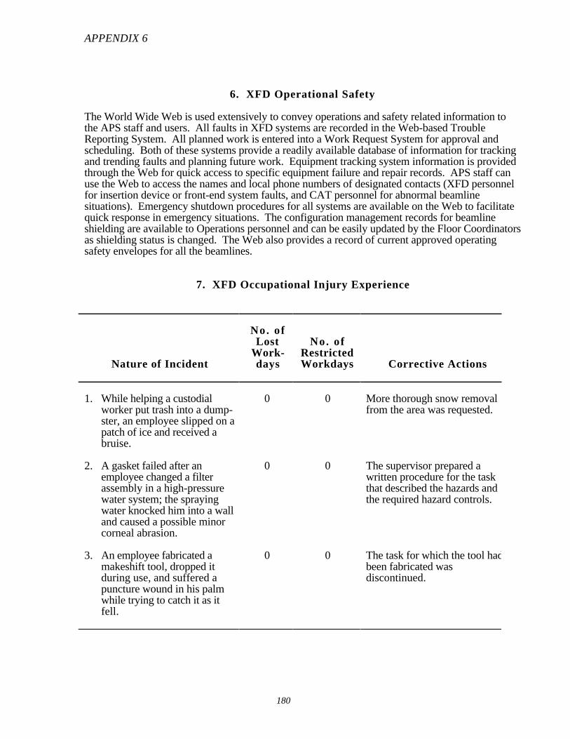
APPENDIX 6
180
6. XFD Operational Safety
The World Wide Web is used extensively to convey operations and safety related information tothe APS staff and users. All faults in XFD systems are recorded in the Web-based TroubleReporting System. All planned work is entered into a Work Request System for approval andscheduling. Both of these systems provide a readily available database of information for trackingand trending faults and planning future work. Equipment tracking system information is providedthrough the Web for quick access to specific equipment failure and repair records. APS staff canuse the Web to access the names and local phone numbers of designated contacts (XFD personnelfor insertion device or front-end system faults, and CAT personnel for abnormal beamlinesituations). Emergency shutdown procedures for all systems are available on the Web to facilitatequick response in emergency situations. The configuration management records for beamlineshielding are available to Operations personnel and can be easily updated by the Floor Coordinatorsas shielding status is changed. The Web also provides a record of current approved operatingsafety envelopes for all the beamlines.
7. XFD Occupational Injury Experience
Nature of Incident
No. ofLost
Work-days
No. ofRestrictedWorkdays Corrective Actions
1. While helping a custodialworker put trash into a dump-ster, an employee slipped on apatch of ice and received abruise.
0 0 More thorough snow removalfrom the area was requested.
2. A gasket failed after anemployee changed a filterassembly in a high-pressurewater system; the sprayingwater knocked him into a walland caused a possible minorcorneal abrasion.
0 0 The supervisor prepared awritten procedure for the taskthat described the hazards andthe required hazard controls.
3. An employee fabricated amakeshift tool, dropped itduring use, and suffered apuncture wound in his palmwhile trying to catch it as itfell.
0 0 The task for which the tool hadbeen fabricated wasdiscontinued.
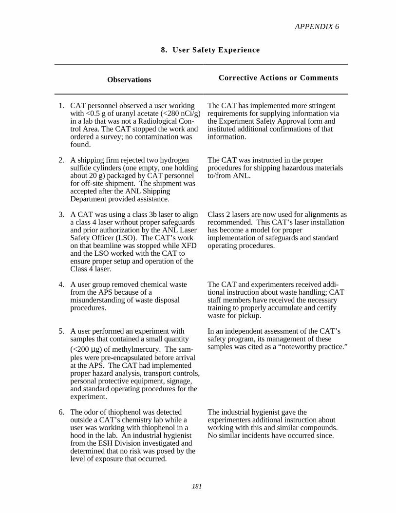
APPENDIX 6
181
8. User Safety Experience
Observations Corrective Actions or Comments
1. CAT personnel observed a user workingwith <0.5 g of uranyl acetate (<280 nCi/g)in a lab that was not a Radiological Con-trol Area. The CAT stopped the work andordered a survey; no contamination wasfound.
The CAT has implemented more stringentrequirements for supplying information viathe Experiment Safety Approval form andinstituted additional confirmations of thatinformation.
2. A shipping firm rejected two hydrogensulfide cylinders (one empty, one holdingabout 20 g) packaged by CAT personnelfor off-site shipment. The shipment wasaccepted after the ANL ShippingDepartment provided assistance.
The CAT was instructed in the properprocedures for shipping hazardous materialsto/from ANL.
3. A CAT was using a class 3b laser to aligna class 4 laser without proper safeguardsand prior authorization by the ANL LaserSafety Officer (LSO). The CAT’s workon that beamline was stopped while XFDand the LSO worked with the CAT toensure proper setup and operation of theClass 4 laser.
Class 2 lasers are now used for alignments asrecommended. This CAT’s laser installationhas become a model for properimplementation of safeguards and standardoperating procedures.
4. A user group removed chemical wastefrom the APS because of amisunderstanding of waste disposalprocedures.
The CAT and experimenters received addi-tional instruction about waste handling; CATstaff members have received the necessarytraining to properly accumulate and certifywaste for pickup.
5. A user performed an experiment withsamples that contained a small quantity(<200 µg) of methylmercury. The sam-ples were pre-encapsulated before arrivalat the APS. The CAT had implementedproper hazard analysis, transport controls,personal protective equipment, signage,and standard operating procedures for theexperiment.
In an independent assessment of the CAT’ssafety program, its management of thesesamples was cited as a “noteworthy practice.”
6. The odor of thiophenol was detectedoutside a CAT’s chemistry lab while auser was working with thiophenol in ahood in the lab. An industrial hygienistfrom the ESH Division investigated anddetermined that no risk was posed by thelevel of exposure that occurred.
The industrial hygienist gave theexperimenters additional instruction aboutworking with this and similar compounds.No similar incidents have occurred since.
APPENDIX 6
182
.9. Safety Surveys and Results
Between August 1997 and the time of this writing, XFD has conducted three self-assessments ofits safety programs. In each case, a comprehensive survey of employees at all levels was used togather the needed information. The scope and results of each self-assessment are summarizedbelow.
XFD Integrated Safety Management Self-Assessment, August 1997: Thisself-assessment was designed to evaluate the degree to which XFD’s activities incorporatethe seven guiding principles and five core functions of ISM. Most XFD employeesindicated that they are fully participating in, and seeing the benefits of, this integratedapproach. The results also indicated that XFD’s primary opportunity for safetyimprovement was in the area of supervisor participation in inspections. The Divisionfollowed up by having its managers implement the DuPont Safety Training ObservationProgram.
XFD Hazardous Materials Management Practices Self-Assessment,December 1997: This self-assessment looked at the degree to which XFD personnelunderstand and carry out assigned responsibilities and comply with ANL requirements forhazardous materials management. The results indicated a high level of awareness of andcompliance with the requirements for procurement, storage, use, labeling, hazardcommunication, waste management, etc., and the application of good managementpractices. Some areas for improvement were identified, and corrective actions wereimplemented by XFD Group Leaders. These actions included initiating regular inspectionsof chemical labs and satellite waste accumulation areas and reminding PrincipalInvestigators of the need to develop work plans and consult more closely with the LabSafety Captains.
Gap Analysis for the Experimental Facilities Division, August 1998: Thisself-assessment was similar in scope to that of August 1997 (discussed above). Thesurvey questions were designed to measure the degree to which XFD’s practices met ISMcriteria. Only minor gaps were identified. A corrective action plan is being formulated; itwill include efforts to better communication existing policies, guidance, and inspectionresults to XFD personnel.
10. Independent Assessments and Audits
During FY 1998, XFD was the subject of independent oversight activities and audits covering thefollowing areas:
Chemical Vulnerability, January 1998: This audit was conducted by a team ofrepresentatives from ANL’s ESH/QA Oversight Group (EQO) and the DOE. The activity verifieddeterminations previously reported by XFD in conjunction with its December 1997 HazardousMaterials Management Practices Assessment (see above). No findings resulted. The reportrecommended the integration of Divisional inventory databases into CMS, as XFD was alreadyplanning to do.
Radiation Protection Program, March 1998: ANL's ESH Division assessed the radiationprotection programs implemented by both APS Divisions. The XFD program was found to be incompliance with 10 CFR 835 and Chapter 5 of the ANL Environment, Safety and Health Manual.
APPENDIX 6
183
The resulting report contained no safety-related findings or observations, and took note of fivenoteworthy procedures or processes.
ESH Training, April 1998: This review was conducted by representatives from DOE’sArgonne Group as part of an ANL Program Review. No findings pertaining to XFD resulted; thereport characterized XFD training records as “well maintained and complete” and acknowledgedXFD’s noteworthy practice of prohibiting certain activities unless required training had beenverified.
Hoisting and Rigging Program, May-June 1998: This ANL-wide review was arrangedand conducted by EQO with technical support provided by various ANL staff members. Nofindings or recommendations pertaining to XFD resulted.
Biosafety/Infection Control, July 1998: This review was conducted by representativesfrom DOE’s Argonne Group as part of an ANL Program Review. No findings pertaining to XFDresulted. However, the DOE did recommend that XFD obtain evidence of training completed byAPS users from other ANL Divisions. (XFD had already made arrangements for access to theTMS records of APS users who are not ANL employees.) XFD will inform the CATs that it mayask for evidence/documentation of training during experiment safety review oversight activities(see Section 12 below).
11. User Experiment Safety
The CATs have the primary responsibility for safety reviews of proposed experiments. Theinformation needed to perform these reviews is obtained through the use of a standard APSExperiment Safety Approval Form (ESAF). In addition, some CATs have instituted more detailedexperiment and safety questionnaires to be submitted with users’ proposals. The forms arecompleted by the experimenter, who describes the materials and equipment to be used, the knownhazards, and the ways in which these hazards will be mitigated. The CAT Director or designatedsafety coordinator reviews the information and makes recommendations as needed. The CATsmay ask the XFD Experiment Safety Review Coordinator or the XFD ES&H Coordinator toadvise them on mitigating potential hazards, or to participate in the review process. When thesafety review is completed, the CAT Director or designee lists any required hazard mitigationmeasures and signs off to indicate approval of the experiment. Before the experiment may begin,an individual designated by the CAT also verifies that all required safeguards are in place and signsthe form. An APS Floor Coordinator posts the form at the beamline for the duration of theexperiment. An XFD committee oversees the CAT experiment safety review process to ensurecompliance with ANL safety requirements and to provide additional guidance on safety-relatedissues. This committee meets weekly to discuss ongoing and future experiments. The XFDExperiment Safety Review Coordinator serves as the liaison between the CAT Safety Coordinatorsand the APS.
The numbers of users and experiments at the APS, as reported on ESAFs, greatly increased duringfiscal year 1998; 540 experiments were carried out in the course of 2,012 “user visits” involving822 different individuals.
The APS is currently implementing two methods to assist the CATs with their experiment safetyreview process. The first, a Web-based system for the submission and approval of ESAFs, iscurrently in final beta testing and is expected to be implemented in early FY 1999. When a usersubmits an ESAF on-line, it will be transmitted to the appropriate CAT and, concurrently, to theXFD Experiment Safety Review Coordinator, who will be able to insert comments about anysafety concerns the APS may have; those comments will be automatically transmitted to the CAT
APPENDIX 6
184
Safety Coordinator. The XFD Experiment Safety Review Coordinator will be notified when theCAT approves the experiment. When the users are ready to begin the experiment, the ESAF willbe printed out for sign-off and posting as described above.
The Web-based system also includes safety guidance for the experimenters and the CATs. Theguidance is based on the materials, hazards, and equipment that the experimenter checks off on theESAF. The system will display either the requirements for working with a particular hazard or alink to other documentation on mitigating the hazard.
The second form of assistance that is now being implemented is a standard set of APS “experimentsafety envelopes,” which group proposed experiments on the basis of hazards. These envelopeshave been developed in accordance with a graded approach that takes into account the severity ofthe hazards. Each envelope specifies a set of controls, including procedural and engineeredcontrols, restrictions, shipping guidance, training requirements, and additional safety guidancereferences, that is sufficient to provide for the safe conduct of all individual experiments in thatclass. In addition, a set of Safety Guidelines for certain hazards is appended to the safetyenvelopes document. The guidelines provide more detailed information for working withindividual hazards. When reviewing and approving an experiment, the CAT chooses theapplicable envelope(s) and ensures that the specified controls are in place. The envelope(s)applicable to a given experiment are also listed on the ESAF that is posted at the beamline duringthe experiment.
The nine APS Experiment Safety Envelopes are:
1. APS Base Hazard Class2. Cryogenic Hazards3. High Temperatures4. Class 3 and 4 Lasers5. High Pressure Systems6. Chemicals7. Biosafety8. Radioactivity9. Other Hazards
The envelopes are currently being reviewed by the APS Research Directorate. The envelopedescriptions will be posted on the Web and put into effect as soon as they are finalized. There willalso be a link from the Web-based ESAF Safety Guide, which will list suggested envelopes foreach experiment based on the hazards noted on the corresponding ESAF. The final determinationof applicable safety envelopes is made by the CAT during the experiment safety review process.
12. Safety Oversight
XFD Walkthroughs
During FY 1998, XFD conducted a number of routine walkthrough inspections of spaces occupiedby XFD employees and APS users. It also conducted one inspection in response to an ImmediateAction Request from the ESH Division.
Ergonomics Walkthrough, September-October 1997: XFD personnel inspected officespaces as part of an ongoing self-assessment that focused on ergonomic issues. At XFD’srequest, an ergonomics specialist from the ESH Division participated. The observations resulted
APPENDIX 6
185
in substantial modifications to two XFD staff members’ offices and minor modifications in otherlocations.
General Walkthrough, October 1997: XFD personnel conducted a general walkthrough ofXFD- and CAT-occupied spaces. The walkthrough resulted in 25 observations that requiredfollow-up; three of these remain open at the time of this writing.
General Walkthrough, February 1998: XFD personnel conducted another generalwalkthrough of XFD- and CAT-occupied spaces. The invited participants included a fire protectionspecialist and a safety specialist, both from the ESH Division. The walkthrough resulted in 13observations that required follow-up; all have since been closed out.
General Walkthrough, July 1998: XFD personnel conducted another general walkthrough ofXFD- and CAT-occupied spaces. The invited participants again included a fire protection specialistand a safety specialist from the ESH Division. The walkthrough resulted in several observationsthat required follow-up; all have since been closed out.
Immediate Action Request, July 1998: The ESH Division asked XFD to review thepotential for localized oxygen-deficient or other hazardous atmospheres. In response, the XFDES&H Coordinator and User Technical Interface Group Leader conducted a walkthrough of XFD-and user-occupied spaces. The only observation of note was a previously identified concernrelated to the use of liquid nitrogen. Owing to anticipated changes in the liquid nitrogendistribution system and the lack of any previous problems, further investigation will be deferreduntil the new system is put in place. However, the potential for catastrophic releases will beconsidered during the design of the new, centralized distribution system.
Independent CAT Safety Assessments
To take advantage of the CATs’ growing experience in managing their own safety programs at theAPS, XFD has initiated the formation of three Independent CAT Safety Assessment groups,within which the CATs conduct reciprocal assessments of each other’s safety programs. XFD hasprovided a set of model assessment criteria. Each of the CATs currently in residence at the APShas named a representative to one of these groups, and the XFD Experiment Safety ReviewCoordinator is an ex officio member of all three groups. Each CAT is reviewed by the other CATsin its group at least annually, on a rotating basis. After a given CAT is reviewed, it receives awritten report (which is copied to XFD) identifying action items and a schedule for completingthese actions. The groups are also encouraged to make recommendations to the APS for enhancedsafety support. Groups I and III have already started their assessment programs, and Group II willdo so in early FY 1999.
The CATs’ group affiliations, sector assignments (in parentheses), and assessment dates areshown below.
Group I Group II Group IIIBESSRC (11, 12) 2/98 1/99 IMM (8) Bio (sector 18)CMC (9) 6/98 4/99 MHATT (7) CARS (sectors 13, 14, 15)DND (5) 9/97 10/98 m (6) IMCA (sector 17)SRI (1, 2, 3) 7/97 7/98 PNC (20) MR (sector 10)
UNI (33, 34) SBC (sector 19) 6/98
The Independent Safety Assessment model criteria include (but are not limited to) the followingsteps:
APPENDIX 6
186
1. CAT safety overview presentation (CAT safety organization, communications, training,operations, safety planning, safety inspections, unique hazards, incident reports, follow-ups,lessons learned, etc.).
2. Questions by assessment team and inspection of safety-related records.
3. Walkthrough of CAT sector(s) and labs.
4. Executive session and close-out (report writing, action item identification, mitigation schedule,report to CAT of findings, recommendations to APS for safety improvements, and reportdistribution).
13. XFD Safety Communication Activities
Safety Communication with XFD Employees
Group Meetings: The XFD ES&H Coordinator attends all meetings of the Experimental FloorOperations Group; since the XFD Floor Coordinators belong to this group, user safety issues arealways a subject of discussion there. He also participates in most of the meetings of the other XFDgroups, where he discusses general and group-specific safety issues.
Division Meetings: Safety issues are discussed at most XFD Division Meetings, which areheld approximately twice a year. At the most recent Division Meeting, the Division Directorreviewed the findings of XFD’s August 1997 Integrated Safety Management Self-Assessment.
Safety Communication with APS Users
XFD has several forums for regular safety-related communication with APS users. At thequarterly APS Research Directorate Meetings, XFD management formally presents new safetypolicies and guidance to the CAT Directors as a group, and discusses any generic safety concernsthat are best addressed by the CATs in a “top-down” manner. At the weekly “CAT Chats,” XFDmanagement discusses safety issues directly with the CAT staff members who manage and carryout the CATs’ day-to-day activities on the experiment floor. In addition, safety information ismade available to the entire user community both through the quarterly publication CATCommunicator (which is mailed to about 1600 APS users) and via the APS Web site.