Embed Size (px)
Citation preview

//i("..RMINE T, pl:RnAPATO..~Anl"'''H PASSAIC VALLI:Y SI:WI:RAGI: COMMISSIONI:RS
SEYMOUR .4. LUSETKINCHIE"I"' ESGJS!E:£;:t
"OUEHT ~ DAVENPORT'c.c C"A~H"'A.N
600 WILSON AVENUE
NEWARK, N.J. 07105
(201) 344-1600
JAMES V. SEGRETOCHIEP COUNSEl..
, 10104"5 .I. CIFELLI-""CHAEI.. A. GIULIANO
tli:N W. CORCONJ05£PH M. KEEGANCH"RLES A. LAGOSCOMMISSIONERS
MRS. CHARLES T. SCH.lr.ECEL.Ct.ERK.TREASURER
January 21, 1976
Mr. C. E. Maginn, Jr.,Division Superintendent - EssexElectric Transmission and DistributionPublic Service Electric and Gas Co.938 Clinton AvenueIrvington, New Jersey 07111
Dear Mr. Maginn:
On Wednesday, January 14, 1976, while conducting a routine inspec-tion to Lawyer's Ditch, a tributary of the Passaic River adjacent to thePublic Service Essex Generating Station, PVSC Inspectors encountered employeesof the Distribution Division of Public Service pumping an oily type materialout of a manhole onto the ground. This liquid formed a large puddle andbegan slowly seeping into the ground adjacent to Lawyer's Ditch, which wasabout 75 feet from the manhole. Besides the material reaching the ditchvia seepage, that residue which remains on the surface will reach the stream
"- during each storm and therefore PVSC deem this as an unacceptable method ofdisposal by Public Service.
In the past this type of operation had been called you your atten-tion and, in fact, we have a letter on file from you dated June 19, 1975which informed us that your manhole cleaning truck will discharge into yourskimming facilities located in Irvington and at your Roseland ~witching Sta-tion.
Mr. D'Ascensio contacted your Mr. Ray Fernandez, who was the StationEngineer of the Essex Generating Station located adjacent to this area, andcomplained of this operation.
Mr. Rutledge of the Essex Distribution Division called ~~. D'Ascensioon January 19 at approximately 10:40 A.M. and explained that the normal methodfor removing liquids from the manhole was to pump this material into a tanktruck, discharging it subsequently into your oil skimming facilities as pre-viously explained by you. Mr. Rutledge then assured Mr. D'Ascensio that -theEssex County Distribution Division was aware of this requirement, but thatthe occurrence of January 14 was caused by the Hudson County Division personnelwho were not aware of this prohibition. Mr. Rutledge then stated that subse-quently all personnel concerned had been informed of the prohibition and thathe would notify PVSC in writing to that effect.
TIERRA-B-001286

'- January 21, 1976 Page 2
Later on, just before noon on January 19, while Mr. D'Ascensiowas rechecking the area, he encountered another Public Service truck whichhad just completed pumping out a different manhole in that area, and Mr.D'Asccnsio noticed evidence of oil in the street. Upon questioning thedriv~rs, they admitted that they had pumped the residue from the manhole tothe street.
It is obvious that this method of cleaning manholes causes pollu-tion of our streams, if not immediately in some cases, then subsequentlyafter the first rain, and I believe it is imperative that Public Service en-act a more firm policy than has been enacted in the past, to see that themethods which you have indicated are provided for, are truly enforced.
Please reply to this letter informing PVSC as to exactly what isbeing done so as to insure that this type of violation which we have observedwill not be repeated again within the PVSC district.
Very truly yours,
PASSAIC
S. A. Lubetkin,Chief Engineer
SAL/klCertif ied Mail~rr. Rutledge - Essex Distribution DivisionMr. McAlpine - Hudson Distribution DivisionP.V.S.C.Messrs. Segreto, D'Ascensio, Goldberg, Cuccinello
TIERRA-B-001287

(..... 'X ... " ~. \
."
captain of the PortU. S. Coast Guard
Governors IslandNew York, NY 1004Tel: (212) 668-7920
16465
Gentlemen:
This is to inform you that a pollution incident was discovered atSEd-Go £55- 6£ -N STAT,oN on 76 )fAN 1981!,.
for which your V'essel faci11ty may be considered responsible.Under Federal Statutes, the United States Government has aninterest in this incident and further, may take appropriateaction to minimize any damage which may be caused by thispollution.
The discharge of a harmful quantity of oil is a violatin of theFederai Water Pollution Control Act, as amended (33 USC 1161).Under this Act, you are responsible for taking proper action toremove the pollutant and adequately mitigate its effect. Removalis being done properly if it is in accordance with FederalStatutes and regulations and the procedures and criteria of theNational Oil and Hazardous Substances Pollution Contingency Plan(40 CFR 300). The adequacy of your actions shall be determined
by the U. S. Coast Guard on Scene Coordinator, captain R. C.NORTH or his representative. As long as you are taking adaquateaction in this matter, Federal action will be to monitor progressof cleanup activities as well as to provide guidance asnecessary.
If it is determined that you are not taking prompt andappropriate actions to contain, cleanup, and dispose of thepollutants, Federal response may be initiated. Your~e~~el/facility will be held responsible for all costs incurredby the Federal Government as set forth in Section 311(f) of theFedral Water pollution Control Act. Should you require furtherinformation concerning this matter, you should contact thePollution Response Office at (212) 668-7920.
Sincerely, '~...J,,~~~..8 t1(.u-.~
COTPNY-13 (Rev 7-87)
TIERRA-B-001288

IIWM 00·1l'INO New Jersey Department of Environmental Protection
Division of Hazardous Waste Managementc;/ ~01 - J-g -/?'SO 2 Babcock Place
West Orange, N.J. 07052(201) 669·3960
NOTICE OF VIOLATlON
DATE / /it,/q II
NAME OF FACILITY j)SEtb /Essex ~/a/'~~ ,rtt:i6~,",/7/
LOCATION OF FACILlTY;,a= !8?y&O/lc! d~l/i) i lkiA/iP/C) Es !'CX
NAME OF OPERATOR;J?e Rv 5S FuR/ltC'.e I
10 NO, _
You are hereby NOTIFIED that during my inspection of your facility on the above date. the following
violation(s) of the Solid Waste Management Act. (N.J.S.A. 13:1 E-1 et seq.) and Regulations (N,J.A,C,
7:26-1 et seq.) promulgated thereunder and/or the Spill Compensation and Control Act. (N.J.SA
58: 10-23.11 et seq.) and Regulations (N.J.A,C. 7:1 E-1 et seq.) promulgated thereunder were observed,
These violation(s) have been recorded as part of the permanent enforcement history of your facility.
DESCRIPTION OF ViOLATION 11. if:.5.,LJ, 56 ..10 .-d 3. /1 (cJD,scA':r 0'/ <9 j"~"'f",5 'fV6d,vw~ /5 j2/ok b<tfer' (F'";"'1"7,b"...."/ie_e bc>/?? -.:§.e>'c.r;'S v/l.'£'"...:;/('I"6' tI .,.£;;/ l/.I1e)7 :;;;>
Remedial action to correct these violations must be initiated immediately and be completed by
A S /t. .iJ. ' Within fifteen (15) days of receipt of this Notice of Violation, you
shall submit in writing. to the investigator issuing this notice at the above address, the corrective
measures you have taken to attain compliance. The issuance of this document serves as notice to you
that a violation has occurred and does not preclude the State of New Jersey. or any of its agencies from
initiating further administrative or legal action, or from assessing penalties. with respect to this or other
violations. Violations of these regulations are punishable by penalties of $50,000 per violation.
Investigator, Division of Hazardous Waste ManagementDepartment of Environmental Protection
TIERRA-B-001289

Forn.' DWM.()511186
'"' C)NE~SEY DEPARTMENT OF ENVIRONMENTAL PROTECTION
DIVISION OF WASTE MANAGEMENTPage _)_Of L
INVESTIGA nON
CASE #:
INVESTIGATOR: r; r ~lA (; o../LtLOCATION: P5 E" e- r;:.~..,\ e.rc~~"""kADDRESS: go.. y rt-ttJ",.d 81",c/ t>
,,d./e- ..-&'c< r-h County. 13c.;.>-ex-
DATE: ;;..b~/9:(f+t:< f",; ...,pROPERTY OWNER: ~_...:....----.::::::......:~-=------
DWM FILE #: 67-: I L{ ~ ;;) '5 (TIME ARRIVED: S-.·d-<:l P f"-"[.
TIME DEPARTED: {p :Od 1'7n-Pr;:+- (i:.
MAILING ADDRESS:, _
BLOCK:
LOCATION TELEPHONE #:
EPA ID #: ~~ _
LOCAL HEALTH DEPT, REP, TELEPHONE #: _
ORIGIN OF COMPLAINT: TELEPHONE #: _
NATURE OF COMPLAINT:
PHOTOGRAPHS TAKEN: ~~~~~ _
LOT: RESPONSIBLE PARTy _
-- ADDRESS:
SAMPLE #: __ 4CC-_Jt:;....-'---'- _
~3>~~O fj-~ /10-". k(k~r9f,.~V! Cr ";-5 c. 4. CAr-fr C< crt- P> £ -f-r.i: • g"t?1-1. "-crt:L +"'17-5fc ...-r,,, th g-e."""-,,,,;-K..J rt-.., > afro'CA!..- £2rcJv.,<IJ #~ &vr-rc;/tc..Ob;,5'-p ~g;=2aM ez/~3 -+- ~4 ~ ·rh.~ 14I((JtA.!,,~ q;.cc tit-e...
''ik· ~
I I' V C i---
-- - --Q)
-7
;J"- a v'. "..(e-cI tz,,f'
/
C; ( c· ~"- " £. I ..,', ir;;
Supervisor Signature
COPIES: White, D WMFile Yellow· Local Health Dept. Pink, Investigator
TIERRA-B-001290
o oF"rm DWM.QSl B1186
NEW JERSEY DEPARTMENT OF ENVIRONMENTAL PROTECTIONDIVISION OF WASTE MANAGEMENT
Page--=-of L
INVESTIGATIONq f - 0 t -JR' ~/i(sP
2-/~3/'1:1CASE #
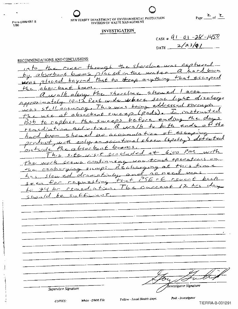
RECOMMENDA nONS AND CONCLUSIONS:
/a A-Ar..l 10<9<."-
/:L
Supervisor Signature
COPIES: White - DWM File Yellow, Local Health Dept. Pink • Investigator
TIERRA-B-001291

.~, ..~- ~
ell //91/7// ?s:t:=!6 W,C5 /.4[//eclr.?c/ /~ /25jJO/7se;r~ d/) ~ ';/./151('./''" /-:~c.cko/ r"f,p/ c:z d// {//lc1e'jI'0vi1d
!e/CSC?/7e -r;?-~ ~/lr /'~ ~?'s r:;~/l~ /0 .6e k,cL-/-?J ..'! ! "cR,R/~/l/ ~I rAe s(~ -Z ,/7/e/ w/I{, ~p f0se/ h,r/7~//
.. !.?/7 6:'v,ro;/l?ed:k1 &.f//:Jce/ r;/" /?5.e:~s ,~ /c~r;P"r~/7/ecl
~'I'iAiii ,#)e 0/7 0 hv/ c~ /..fe ~c//0,i
j
..j
~ . q~ /b2./l..o I"r ¢#/e/~/y c::,r ~ i"d (jJ)' s/v /r:k;~/7 v/l rhe
/!uoJeJ-J,: /'/r h;"c" C'd~,;e5r rc r.i{- A3:.e/ ":v-,,f/C-4 ~
#~ ~oc;.-/~-,tX' 9~//.;./J y /:,jCi/e ?~{?v/l cI 5r/:;t'4'/ .p
TIERRA-B-001292

TIERRA-B-001293

L· --Ir'llc" if 5! \ ~\,~J1\~ c? ~\!) ~ J \~ r ,'J .,; 0 STATE OF NEW JERSEY, -\~A ~./ DIlP TMENT OF LAW AND PUBLIC SAFIlTY k' E eEl V E 0
(] 'YJ\tJ''1 OFFICE OF THE ENVIRONMENTAL PROSECUTOR'
~N MAR 261991MEMORANDUM
Hf\ZARDOUS WASTEENfORCEMENT~3·Jr;1
TO: James Hamilton, Assistant Director for EnforcementDivision of Water Resources
FROM:
Wayne Howitz, Assistant Director for EnforcementDivision of Hazardous Waste Management
Kevin P. Moynahan \(~r"'"Assistant State Environmental
DATE: March 20, 1991
prosecuto~ JE C IE H V IE: II:»APR 4 1991
SUBJECT: PSE&G - Essex Generating StationOEP *446
Attached is an investigation report from the New JerseyMarine Police concerning a discharge on February 2, 1991 ofKerosene from the PSE&G facility to the Passaic River.
This Office is forwarding the information to your respectiveenforcement elements so that the NJDEP may take any appropriateenforcement actions against PSE&G and/or any other partiesresponsible for this discharge, if the NJDEP has not done soalready.
I would appreciate being directly copied on any enforcementactions your elements may take in this matter.
If there is a need to discuss this further, please contactme at 2-3924.
/juattachmentc: Steven J. Madonna, State Environmental Prosecutor
Thomas F. Flanagan, Administrator
TIERRA-B-001294

.-
'-
/' ..-.n..,. .•
NEW JERSEY STATE POLICE INVESTIGATION REPORT I .C ..............
I ' .,., ~.... """ •. ---- ..... :.' ...... ~)1e~..ark 3av
j """._ I J ;- ._. '.0 ~... '"c_ 'I •
C1.ear -.: ....X -.: '( I -. - "'C
:. 3_ I '1.""- ., Jftt c~ I 5 · '..1 t ~- I ..
:' 1,.i..Q 90 :~I" I 7 I, I ? I 01.•. :, .... ' I"CIOIM ia..xlllilllllft
Pollution (Kerosene) 2.3::-29'l.,•..~....
:ll.;- ...
State Of ~ew Jersey;,. ;l.01. ..~-_ .....- 201-578-a173
~S? ~ ~OO Corbin St. Port ~ewark. N.J. 07114~ James Stewart 9624
Leak in unde~round oice allc~ed ~erosene to enter ~.J.State ~ters.J7/_ I ]I, 1_ '». - - - I olO - ~- 1'1::- 4L .._ ..... s_ Q. ".1.".• 'l....... -
dIl __ 'x" '."';SI'. s.rs --~ -~ --'-- --tl 5_111: '.-~,..,.... --""-' ....... "- '-. ---~ ---...... -
1I.~_.___M.r_
17._ ... _ ..UM.
------;"fA: T..Joe-- 11'IL_e--lo.s-,,-Active Invest.
!At a-.a'SI;InmONII - 1.4l: ... l-.ty A_ ....OCWN- ~ '_68.......s~ - c_ Acuan r.... Indulle ~ ... a..._.", I~ __ F'tIwaI EYICIIMe FouIlCl - WMIw. lIV w.... - 0 r..... S-'....,... -1"_ ot v_. w~ p..,.e-- - S_ca -ANCft Victim ~ ~ ~_ - A1QCI'I$~ - e-t "- - AI NCIC """1_ - ~ 0---..
February 2. 1991 ; This date the undersijpJed alaDg vitb MPO 1ArIgill 9706 aM •Mm...BI~.lha9754 wre on patrol in the area of the Passai~ewark. 'Ibi 5 off'; cprQRuri.ecl a sheen on the .. t~urface 100 feet fran shore of PSF&(; Essex C.enerar; ngSot-anon 155 Raymgnd Blvd. Newark, Nul. 07105, 201-430-8964. Also it was nhsermt that€rem the at. 1&9 S'kywy, the area had j n ph,. e a contai men t Ixxm stretched along theshereli". northward for approximately tOO yard,. On approach to the Jxxm T observed ,that the product ins; de of the Man Wi' 5 .scapi og wi tb tbe j nMUDd tide 0, vena, T [.thm...spcke wi th Cbd s Cj es 1an: z~ of Cl pan HartXlTs T'X 201-805-9355; 250 T ackl aM Or- _ !Middlesex, N.J. a88~.6.-.MI:, CipsJarrzyk. advised, that on Tannary 28, "1991 PSF&Ghadrecp1e,ted their seMee, to c""ta;" and clean the are. dlle to an "rvfergmurvf pipeleaking kernseDe I was furt"e,. advj sed that ,] ean HarMrs had az:r:iyed. at IpFOxirnatel:.. I5.lOO PM em 1-28-91, and sirep that date tn 2-2-91 tbey bad Tec""UecI app=&imetely15,000 gallons of IDixed water and urosene of wch 6,000 gallons WIre keroSine. I17. __ ,,.,..r_ .. ~~ IS."" I"~·"-' 1"'__ •__ -MPOJ... St...-rt ~ 1 of 2 2-2-91
.JI""'7 ~ ,l- 1&~~:::-';;"-"""'-=-::"'::=-'I""!I.~-,-T-I-ER-R-A--B---OO-1-'295v c:h_,,_. __

'. cjl,JiIIC'" .. 'lIr 1;:;;0 I "·0..... 0' ...... ,,~ I' ;~~~~;;- 1~ewark Bav
..........._........_ .......- .............._.__......_.-_·_·········i······:.:;O··_:;·_·_····-e-· __ ···_··--··_·h·; ...__._:;-.;.;...._.._._.._-...._........_......._..................."'--" I_._._...On ...lMQ....!1lpp;Q~;LIDat~.y._~ ....r.ee t_ ... ;:qn.~hi~~·L_L~S. ...9..U~c~;:._Q.b$.g{~.j.n...~ ..._...._..__.
I..e.:<caVa.~;..9.Jl..g;i.~.~l.LJi.U~~...~~~Q_~._~~._~f.l.d'Llt~~..j,p~ ...:(i~':L.i.tQy;j4_~.~~r .._~QWld ....i..~..and ...._~-=....What. ...;.,:M...Jg~~~f;..ld-q_~~g$.~~~ tc.~e$._i..Q~;:.n8-Qn....~Qp._Q.t.._~~1-6.:rn!JI'l(t.:"'a.te:r:.-C:ean._' I:::~~~;~ ...had....a_$.igbQ.n...hg$ •. _~.t._.tne_',",a ~et'S....~: ac.~ ..ski:rmj,(Ii-.~t~t__anci ....~.e.tQ.s.en.e....""n:'C:i. __ I
!t~a$....~t;Ul...~J:Lf~~ ...ir;:qt.XId. sa tura t;'Qn_.ar.~::Ltiae __\l!-a.ter.......L:.(a.s_.f~.;he.r._adv.:is.~.j~'___ ,,::.~.,.._C1~~.~zy.k_..tha.LagptQld::late.luQ..;QQ-t.u2.~ iall~ms af ke.t.Qsene.J1a.cLl.e.akeQ._ i...fran._the ...pip.eline.L· _ I
.. •.. On ...sc.ene ...._I_therunec:('I"l :::_?~a<i._shif.:.-s.uper.lis.or ...:1aDua.LSar;o._Mr ...3ar.;o I,...adY.i.se<:L.tbat...Qn...Sa.tu.td.a~Jar:l..Oa:/._":5 ~~L=,"'.e-t.:S.CG_oL.'lY...~ki.ni-the ..=i ...·e= _ ,._.fQt. ..i_saurc.JLft:an...a...s.hHtLon-::.e. ..~",'ater.k.~ L;Q.uld 00 t locate it. PSE&:i...personeL:..a.c. __di .ed.....tba.l· -:1c' . ~ . is:! -1991 . e.l¥-J.l·QO !he. ",-'".... s<;.gy£ - UtLQD c.aay__a::.~,l.......:..:. .a..Lapp~xmt. AM. ._"'..'-' ___
.._liaS...Cocctac.ted ... who then issl.:ea;a~~4'Ct.~r aul.s .13~on.sJ15~"he. ____
....&Loa..Jias._"Qtl.tac..:ad.-ei.v.i.s~LJL:4a.s.te.-a."1anagement ::1i ke Walker respcDdsd.-Wc.-issl.:.ec. __ a...CQ.tic.LQLriQlat.:..cILCas~1~·:1::2 ~li~Q.-C201..l£69:.396G...-lbi.s...g£fic.ar.J:h.en.-C.Onuc.:.~.-tbe.JlS~ ...EQllu.tiQn...Res~DSIL"'::':.:..6cd - i920 and the :u DE? L6Ulli69:.3960 via phcee....tQ..._..-adY.ise that kerOSecL.pl:oauc:.... ...a.LSti] J seeping frau Qut of the grolm into tha....wate:l:... _-and....e.scapiDg...-auLc£ the beaned.. 'U"'ea r wa.. also given a...J;CW Of a c1eamsp proposal ;,:-:- :....aean HarboJ::.s.-b:cm ~ . ..saz:~a-. i
I:...H~~."l.:U."LS_t.a.t_i.Qn_<:Q.m:::a:".de~S.E'C E Herklo~as. notified..~bQ aclti.s.e.<Lt."la ::.JUl.J!l.n.Y.~.;:'1 28. l.i'iL~h~.s_s_~a_t.~n.....hA.d inve.!.ti6a.r..ed a sb.aen OD the Pa..s...s.a.i.:...J..i..¥..t~.i ..t1LQ.(LSJ:Ul.r-,,-e--.f Q l;~d • See Inyest F0109115. I
.J.~~.ILti.n.u.~~~=-?J . II,I
i
I,jI
II
I,I
II
iI
II
.
I,
- I,
In. ,..._."-. r.... .......- ~,.... 1&0.. ___ l"·...........-HPO ,-- - 9624 2 of 2 2-2-91s..... ~~-,·J?~
& I- Is.~_2'OA IIf..,. lItl1 IS.Q.~. an TIERRA-B-0012
CQN'iiNU~ 'ilON PAGE
96

,"'-""",U
NEW JERSEY STATE ?OLICS SUPPt.;MENT~~Y INveSTIGATION REPORT I .~" I " ~-Irl
'-.
I 04i J.''EtQ!1''l ~t\l' I .5 :.- ~5 ..., .... ..JiG ..... .,I"e .......... ~ t.~~entIIOrlo I' ._ .....- ._- I JJ;~;:~ I~ewark 9av I :01') 201·57~-~1·3
.., ~"""" IftCloOtW'lis •••••r·. 115=_ - I·~·:I"'·- I : ;~....~/A ....; ..., X 'Pc ...... X .... ... '( IPollution (Kerosene) '2 :".2' ::'lII"ilt1 "' ..... ..:"..... ,..... rI:~ :'s.·...... _ a"-'."'.:11~ ..... .- ,
:
;I."c_ ~._._ ::-So ._, __ .,...:~ ~""''''''''''''':.I."",
State Of ~ew Jersey1 .__ ...
....e- ....- ... :'ft ,'s~ _._- -" . - •.'-- ilS "',"- ..~aOomOflM, 1_'- a................
y...~II.~"'1lO","" N/A N/A ~/A ~/A ~/A N/Am, __ ,Y_ DS.-_i-. 1_ --.£. tiS,S_'" GS. A.--. M'V ....... 'N..-, "iIIt ~ i~ .....'. ... Y• ...
54.~_ ..._ ......... ' .... $1, -~>.rs - - ,.... - L.•. :-1.&"- S7S,e- .... ",- ",--,va
!...'- - - -- ...... -- X-,-- -,~o...- '- - - ,.... - -v., ..., XU"': v• ..., :'( .... ~ - - 100& ...... - L
.......- ...._- ..-..- ~,.:-s_c... •. e-s_c.. ........... t .... ,s-....- S-
O 1 1 0 Adm. Clr. Courtv__
...,LL4t~" 0III'I of P.- ArtWlWllfS_ - :_ ..tomo_ Oft ..... ""-fS __ - 1_~ ~torI - 5..-. - ._ ..O••• aD...... ,. Sincil YM FI-. - Eo..... _ c.......';;l'..-qe - _ A.ddI_ .,,_ of V~ ~_~. wm- - Iv..-. - r __ ._._5_ PfOOIftY- R-..a ~ - Couft A.c_ - ~_ 0-'-- - ...... "-- Sra._ - "taI:ft ....... yicwft P_ '-- il_ i-(
-'I _. ___ .S_":S _.:.-e-_,5_ ... '11....... 'q s. .......:.. .. : ; I
PSE&G Essex Generating Station 155 Ravmond Blvd. Newark. N.J. 071Q5. Fe.bruary 4, 1991 the utJ_g.J~siined issued to PSE&G a SymmoDS • 5.5.l..S.o._who w~s foun4 to be in viq.l~ti..Qn of NJSA 23:5-28. Pros~utors Cop.~fsJJmmons~s deliver~~~~unty Syperior Cpurt Spec.ial Civil ? a:.:..3...-S~etion-A~iined in the ;2J.:U..e.oc.eof the County Court Clel:k
I
;!.. i
II
III
- I'.
--17'1• ...,,..., ..... T., ~~....,'!i ..,. lr6n"Mm/~~MPO J...... Stewart 624 . 10f 1
~~~'-. ~,~.:'\.. 1 __ ."
s...... y TIERRA-B-00129.__ ... 7
'''--

:ll'I'!" , -w
t-----------------------------------------------
_____ AI!CIIP'I' t ....T • ~ __
,-.7-"!."!
- .----------- ------------------~-.
.... ,- "" D,sposmOH OF CASE.... "\ ......... "ADJOURNMENTS: (Da•• I)
TO ""SON ----.c------~ ::. .:. :~.
TO ~ __ =-~.R .. SON-----;<l".-.J
4i • _
.. ;j, .' \. ..... .. ... ...
IAIL: AM~U~": S.. . C CASH.. CJ IOND ~• 't"\ \ -" - - ..\., "". '.\ .-, ,..l ..... ~ -....'...l .... POSTID WITH (Nlme a TItle) - '-'
....... ~. .. yo: ......... "o 'OAnITUAI: AMOUNT.s - DAT1
DISPOSITlON DATI ----Iy: 0 Court or a Vl04 !"
PUA PlNDINQ _
SENTINCE: PlNI S -----_cosn s _JAIL DAY'\~~~!\.. -
• ' OTHER
...
._ omc...·•COM,.1H1'S --=. : C. ;:(' •• Inltrvcdo". Oft Co.. ,) ._-
6-" _.-... ..... ....~..... ~
~Ioo ....." .... .. _ •
. .. -~ I ( "'.":__ " ...a ......~... ••,.... ." ~ ..~ ..~ , ,-., -
., C t :

PUBLIC SERVICE ELECTRICAND GAS COMPANY
RESPONSE TO USEPAAPRIL 30, 199.6
REQUEST FOR INFORMATION
ESSEX GENERATING STATION
DATED: AUGUST 13, 1996
850010001
TIERRA-B-001299

1.0 Background 61.1 Introduction 61.2 Corporate History 8
2.0 General Site Development 102.1 Site Location 102.2 Site Ownership 102.3 Station Infrastructure 11
3.0 Site Processes and Related Operations 133. 1 Low Pressure Turbine/Generators and Boilers 14
3. 1.1 Process Description 143.1.2 Auxiliary Processes , 16
3.1.2.] BoilerWater 163.1.2,2 Non-Contact Cooling 183.1.2.3 Station Sewer System 213.1.2.4 Equipment Lubrication 22
3.1.3 Raw Materials 233.1.4 Products 253.1.5 By-Products , 253.1.6 Maintenance Processes 28
3.1.6.1 Boiler Cleanings , 283.1.6.2 Fireside Cleaning 293.1.6.3 Condenser Chemical Cleanings 30
3.2 Unit NO.7 High Pressure Turbine/Generator and Nos. 25 and 26 HighPressure Boilers 323.2.1 Process Description 323.2.2 Auxiliary Process 35
3.2.2.] Boiler Water 363.2.2.2 Non-Contact Cooling 373.2.2.3 Equipment Lubrication 37
3,2.3 Raw Materials 383.2.4 Products 403.2.5 By-Products 403.2.6 Maintenance Processes , 42
3.2.6. I Boiler Cleanings 423.2.6,2 Chemical Cleaning of Feed water Heaters 443.2.6.3 Air Heater Washes 463.2.6.4 Fireside Wash 46
3.3 High Pressure Unit No.1 473.3.1 Process Description 473.3.2 Auxiliary Processes 49
850010002
TIERRA-B-001300

3.3.2.1 Boiler Water 493.3.2.2 Non-Contact Cooling , 503.3.2.3 Equipment Lubrication 50
3.3.3 Raw Materials , 513.3.4 Products 533.3.5 By-Products 533.3.6 Maintenance Processes , 55
3.3.6.1 Boiler Cleanings 553.3.6.2 Condenser Chemical Cleanings 593.3.6.3 Chemical Cleaning of Feedwater Heaters 603.3.6.4 Air Heater Washes 61
3.4 Combustion Gas Turbines (1963 - Present) 613.4. 1 Process Description 623.4.2 Ancillary Operations 64
3.4.2.1 Engine Cleanings 643.4.2,2 Purge Oil Collection System 663.4.2.3 Equipment Coolers : 66
3.5 House Heating Boiler , . . . . . . . . . . . . . . . . . . . . 683.6 Yard Operations , 69
3.6.1 Coal Handling and Storage , 693.6.2 NO.6 Fuel Oil Handling and Storage 713.6.3 Natural Gas Supply 723.6.4 No.2 Fuel Oil and Kerosene Storage 733.6.5 Diesel Fuel and Gasoline Storage and Use 743.6.6 Ash Handling and Removal 743.6,7 Refuse 753.6.8 Sewage 753.6.9 Dredging Operations , 76
3.7 Demolition Activities ,.................. 783.8 Substation and Switchyard Operations , 78
4.0 Regulatory Programs 824. 1 Effluent Discharges 82
4.1.1 Circa 1948 Effluent Discharges 834.1.1.1 Discharge Canal Outfall , 834.1.1.2 Ash Pit Overflow Outfall 874.1. 1.3 Cable Vault Sump Pump Outfall 884.1.1.4 Ash Lake Overflow Outfall , 884.1.1.5 Drainage Ditch 88
4. 1.2 Circa 1970 Modifications to Effluent Discharge System 894.1.3 NPDES Permitting 894.1.4 Discharges to Passaic Valley Sewerage Commission 92
4.2 Air Permits and Emissions 94
850010003
TIERRA-B-001301

4.3 DPCC/DCRlSPCC Programs , , 984.3.1 Spill Discharge History 100
4.4 Hazardous Waste Management , .. , . . . . . . . . 1104,5 Underground Storage Tanks 1124.6 Floods, Fires and Other Incidents , : 1134.7 Environmental Media Studies! Analyses . . . . . . . . . . . . . . . . . . . . . . . . . . . . . . 117
850010004
TIERRA-B-001302

1.0 Background
1.1 Introduction
The United States Environmental Protection Agency ("USEPN') served Public Service
Electric and Gas Company ("PSE&G") with a Request For Information Diamond Alkali
Superfund Site, Passaic River Study Area, dated April 30, 1996 under the Comprehensive
Environmental Response, Compensation and Liability Act of 1998, as amended, 42 U.S.C.
Section 9601 et seq. ("Request For Information"). By this Request For Information, USEPA
seeks information and records concerning industrial operations conducted at two PSE&G
facilities: the former Harrison Gas Plant in Harrison, New Jersey, and the Essex Generating
Station in Newark, New Jersey.
PSE&G's response to this Request For Information was originally scheduled to be
provided to USEPA within thirty calendar days of receipt of same. USEPA has extended the time
for the submission ofthis response until August 13, 1996.
PSE&G has prepared this submission as its response to the Request For Information.
PSE&G submits that this submission is responsive and, further, it commits to make all relevant
records referenced herein available for inspection at the USEPA's request. PSE&G wishes to
apprise USEP A of certain background information to consider in connection with evaluating this
6
850010005
TIERRA-B-001303

response.
Industrial operations at the Harrison Site commenced in 1902. Initially, the Site was used
as a satellite storage facility for a manufactured gas plant. In 1926, construction of a
manufactured gas plant was completed at the Site and commercial operations of this facility
began. Base load gas manufacturing operations ceased in 1965. Thereafter, the Site was utilized
as a peak-shaving facility operating on average approximately 100 hours per year. Peak-shaving
operations were generally terminated after the 1986/87 winter. The gas plant has been
dismantled. After operations ceased, there was no concerted effort made to preserve or maintain
Plant operating records.
A steam electric generating station commenced commercial operations at the Essex Site in
1915. A substantial portion of the stearn generating facility was removed from service in the
early 1970s and the entire steam plant was removed from service in 1978. The steam plant was
dismantled in 1990. The Site still houses a fleet of combustion turbines which generate electricity
on peak demand days in the summer and winter. After steam electric generating operations
ceased there was no concerted effort made to preserve or maintain Station operating records.
PSE&G has attempted in good faith to locate and review documents potentially relevant
and responsive to the Request For Information. The absence of any organized records has made
this task extremely difficult. This difficulty has been compounded by the long history of the
operations, the nature and scope of the Request For Information and the limited period within
7
850010006
TIERRA-B-001304

which to respond. This response should be considered in this context. PSE&G recognizes its
continuing obligation to 'supplement this response jf information not known or not available as of
the date of this response should later become known or available to it.
Finally, PSE&G advises USEPA that this response was prepared by a team ofPSE&G
employees with assistance from certain external resources. A Project Manager was designated to
coordinate its response to the Request for Information for each facility and each Project Manager
worked with a small team including Company counsel to prepare a response for that facility. The
Project Manager for each such facility is designated as the knowledgeable person for such facility
and has executed the required certification.
1.2 Corporate History
Public Service Enterprise Group Incorporated ("Enterprise") was incorporated in 1985
under the laws of the State of New Jersey. Its principal executive offices are located at 80 Park
Plaza, Newark, New Jersey 07101. It is a public utility holding company that neither owns nor
operates any physical properties. A copy of the Certificate of Incorporation of Enterprise is
produced herewith as Appendix A. Enterprise has two direct wholly-owned subsidiaries, Public
Service Electric and Gas Company ("PSE&G") and Enterprise Diversified Holdings Incorporated
("EDrn"). Enterprise's principal subsidiary, PSE&G, is an operating public utility engaged
principally in the generation, transmission, distribution and sale of electric energy service and in
the transmission, distribution and sale of gas energy service in New Jersey. The agent for service
8
850010007
TIERRA-B-001305

of process for PSE&G is E. 1. Biggins, Jr., Corporate Secretary.
PSE&G was formed in 1924 by the merger, i.nta: alia, of the Public Service Gas Company
and the Public Service Electric Company. The Public Service Gas Company and the Public
Service Electric Company were also New Jersey corporations organized in 1873 and 1910,
respectively. Both entities were, at the time of the merger, wholly owned subsidiaries of The
Public Service Corporation, a New Jersey corporation organized in 1903. PSE&G was, as a
result of the merger, and remained until 1948, a wholly owned subsidiary of The Public Service
Corporation. The Public Service Corporation was dissolved in 1948 and as part of the Plan for
Dissolution, PSE&G became a publicly owned utility.
EDHI is the parent of Enterprise's non-utility businesses: Community Energy Alternatives
Incorporated ("CEA"), an investor in and developer and operator of cogeneration and
independent power production facilities; Public Service Resources Corporation ("PSRC"), which
makes primarily passive investments; Enterprise Group Development Corporation ("EGDC"), a
diversified nonresidential real estate development and investment business; PSE&G Capital
Corporation ("Capital"), which provides debt financing on the basis of a minimum net worth
maintenance agreement from Enterprise; and Enterprise Capital Funding Corporation
("Funding"), which provides privately placed debt financing.
Enterprise Form 10-K for the year ended 1995 is enclosed as Appendix A.
9
850010008
TIERRA-B-001306

2.0 General Site Development
Section 2.0 provides general information relating to the Essex Generation Station's
("Station" or "Essex") location, property acquisition history and Station infrastructure.
2.1 Site Location
The Station is located in Newark, New Jersey on the west shore of the Passaic River
immediately north of the Pulaski Skyway at a river location commonly referred to as "Point No
Point" (see Figure 2.1). The street address is 1S5 Raymond Boulevard.
2.2 Site Ownership
The lands comprising the site of the Station were purchased in a series of transactions over
a number of years. Figure 2.2 presents a summary of these transactions. Available conveyance
instruments are available for inspection.
2.3 Station Infrastructure
Essex began operation in 1915 with four low pressure stoker boilers and two, 22,500
kilowatt (UkW") turbine/generators. In 1916, four additional low pressure stoker boilers were
added. Four more low pressure stoker boilers and a 40,000 kW turbine/generator were installed
A\lIUIl13, 1996 (IO:3lpm) 10S:\USEP A.I04IESSEX.DOC
850010009
TIERRA-B-001307

in 1918. Four more low pressure stoker boilers were added in 1919. Three identical 36.000 kW
turbine/generators and eight additional low pressure stoker boilers were installed by 1924 _
completing the initial phase of Station construction. As of 1924, the Station was comprised of
twenty-four low pressure stoker boilers and six turbine/generators with a combined capacity of
193,000 kW. The low pressure stoker boilers were originally equipped to bum only coal.
The Station also contained electric distribution switching equipment. The switching
equipment included buses, oil circuit breakers, transformers, physical disconnect switches and
transmission and distribution line connections. Circa 1925, the Station became a key feeder point
within the Company's then existing high voltage transmission system. To accommodate this new
operation, additional switching equipment was installed.
In 1937, eight of the low pressure stoker boilers were removed and replaced with two
high pressure boilers ("Nos. 25 & 26"). The two new boilers were designed to bum both coal and
oil as fuel. One turbine/generator (known as "Unit No. 7") was also added. This equipment
increased Station capacity by 50,000 kW. Low pressure (225 psi) exhaust steam from Unit NO.7
was not condensed but was fed to the main low pressure steam header and then directed to the
existing low pressure turbine/generator units to produce an additional 70,000 kWofelectricity.
In 1946, the original Unit No. I turbine/generator was retired along with four low
pressure stoker boilers. A new 100,000 kW turbine/generator, high pressure boiler combined unit
was installed in 1947. The new boiler (referred to as the "New Unit No. 1") provided steam to its
AIlg\III13, 1996 (lO:3lpm) 11 S:\USEP A. I 04\ESSEX.DOC
850010010-_.~._--------
TIERRA-B-001308

dedicated turbine/generator. This boiler was designed to bum coal, oil or gas. With the addition
of the New Unit No.1, the Station possessed its largest electric stearn driven generating capacity
of320,SOO kW.
A major reconstruction of the electrical switching operation was completed by 1940.
Additional switching equipment was installed at the Station in 1946, 1950, 1970 and 1991 to
upgrade switching operations to handle increased electric power routed through the Station for
distribution to customers.
Commencing in the early 1970s, the Station began a phase-out of its steam-powered
electric generation. The last steam unit was removed from service in 1978 and the steam Station
was demolished in 1991.
Commencing in 1963, combustion turbine peaking units were installed at the Station to
provide supplemental generating capacity during peak periods of demand. Combustion turbines
are pre-fabricated, self-contained electric generating units which combust fuel (low sulfur distillate
oil or natural gas) producing exhaust gases that drive a coupled turbine/generator to produce
electricity. The first unit (known as "Unit No.8") commenced operations in ]963. Four
additional units were installed, three in 1971 (known as "Units Nos. 9 through 11") and a fourth
in 1972 (known as Unit No. 12). As of 1972, the Station reached combustion turbine electric
generating capacity of 585,333 kW (nameplate rating).
August 13, 1996 (lO:3lpm) 12 S:IUSEPAI04\ESSEX.DOC
850010011
TIERRA-B-001309

In 1980, combustion turbine Unit No.8 was removed from service. In 1990, Unit NO.9
was replaced with a new combustion turbine unit ("New Unit No.9") with an electric generating
capacity of90,OOO kW, the same capacity as former Unit No.9. Four combustion turbine units
remain in service today with a combined total capacity of 664,333 kW (nameplate capacity).
Available engineering drawings of Station generating and auxiliary equipment are available
for inspection. Figures 2.3 through 2.7 depict the layout of the Station as of 1925, 1940, 1951,
1974 and 1996.
3.0 Site Processes and Related Operations
Section 3.0 provides a description of the electric generation processes as well as auxiliary
and maintenance processes used at the Station Over its operating life. Information relative to the
raw materials used and the residuals generated is also provided.
This section has been prepared from, among other things, information contained in various
available Plant records and relevant corporate history references. In addition, the Electric Power
Research Institute "Power Plant Integrated Systems: Chemical Emissions Studies" has been
referenced to identitY and characterize many of the materials utilized and generated at the Plant.
3.1 Low Pressure Turbine/Generators and Boilers
August 13, 199iS00:31pm) 13 S:\USEPAI 04\ESSEX,DOC
850010012
TIERRA-B-001310

This section presents a discussion of the electric generation process and auxiliary
processes involved with the generation of electricity using low pressure boilers and
turbine/generators. A process flow diagram is provided as Figure 3.1.
3.1.1 Process Description
The Station's initial electric generation process began in 1915 using a combination of
Babcock & Wilcox wet bottom underfeed, coal fired, low pressure stoker boilers and General
Electric turbine/generator units. By 1924, twenty additional boilers and four additional
turbine/generator units were installed. The six turbine/generators were all housed in the turbine
building and the 24 low pressure boilers were housed in three integrated sections, without
separating walls within the boiler house in sets of eight to a section. Table 3.1 provides the
operating parameters for the low pressure boilers and turbine/generator units. Table 3.2 lists the
raw materials used in both the generation and auxiliary processes at Essex.
Steam was generated by burning coal, fed into the boiler at the bottom of the furnace by
stokers. City water was heated in the boiler to an approximate temperature of 5450 F, creating
steam at a pressure of 225 pounds per square inch ("psi"). City water was treated with chemicals
prior to use in the boiler to prevent boiler tube internal scaling and corrosion which adversely
affected boiler tube heat transfer efficiency and created the potential for boiler tube overheating.
The boilers were equipped with forced draft and induced draft fans. The forced draft fans
supplied air via a duct to the boiler from the bottom of the furnace. The induced draft fans at the
AIIg\IOC 13, 1996 (lO:J8pm) 14S:\USEPAI04\ESSEX.DOC
850010013
TIERRA-B-001311

top of the boiler provided draft which facilitated movement of combusted (heated) gases within
and through the boiler. The heated combustion gases passed around the boiler tubes to heat the
boiler feedwater in the boiler tubes to produce steam. A fire brick baftle in each of the boilers
forced the heated combustion gases to turn and pass around the boiler tubes several times before
exiting the boiler through the stack. The residual combusted gases were exhausted to the
atmosphere. This boiler design optimized heat transfer and reduced particulate emissions, as
materials trapped in the combustion gases tended to drop to the furnace floor.
Low pressure steam generated in the boilers was delivered to the turbines by means of
carbon steel pipelines and expanded through the turbines. Each turbine was comprised of a series
of blades attached to a hardened steel shaft. Low pressure steam expanded against the turbine
blades and caused the turbine shaft to rotate at a rate of 1800 revolutions per minute ("rpmn).
Each generator rotor, which consisted of a hardened steel shaft and a series of copper conductors,
was directly coupled to the turbine shaft and thus rotated at the same speed as the turbine. The
generator rotor rotated inside a stator, consisting of a series of copper windings, which produced
an electromagnetic field resulting in generation of electric power.
The steam exited the turbine under vacuum entering the water-cooled condenser located
directly below the turbine. The steam was condensed, and the condensate was pumped to a surge
tank from where it was gravity fed to boiler feed pumps for reuse in the electric generation
process. The non-contact cooling water used to condense the process steam was withdrawn from
the Passaic River through an intake canal, passed through the condenser, and discharged back to
AugIlIl13. 1996 (10:38pm) 15S:\USEPA 104\F,SSEX.DOC
850010014
TIERRA-B-001312

the Passaic River via a discharge canal.
Circa 1933, oil burners were installed in the low pressure boilers. By 1949, all the
remaining low pressure boilers were converted to oil, thus eliminating the use of coal stokers.
Eight low pressure boilers were removed from service and dismantJed in 1937, and by 1955
another eight low pressure boilers were removed from service. The remaining eight low pressure
boilers continued to be available to supply steam to the low pressure turbine/generators until they
were taken out of service circa the mid 19708.
3.1.2 Auxiliary Processes
This Subsection describes the ancillary processes associated with the generation of
electricity using low pressure boilers including boiler water treatment, non-contact cooling of the
main condensers and auxiliary equipment, and the Station's internal sewer system.
3.1.2.1 Boiler Water
The water supplied as makeup to the boilers to create steam was purchased from the City
of Newark water supply. Minerals (such as calcium and magnesium bicarbonates and silica) and
oxygen in city water have the potential to cause scaling and corrosion on the inner walls of boiler
tubes, which in turn reduces the heat transfer efficiency of the boiler and can also lead to
overheating of boiler tubes. The boiler tubes in the low pressure boilers were made of carbon
August lJ. 19% (I0:311pm) 16S:IUSEP AI04\ESSEX.!XlC
850010015
TIERRA-B-001313

steel and were four inches in diameter. City water was initially fed to a surge tank and then
gravity fed to open heaters. The open heaters were designed to drive off dissolved oxygen,
which corrodes boiler tubes and Station piping systems. The removal of oxygen from the boiler
feedwater significantly limited the buildup of corrosion products on the inner wall of the boiler
tubes. Treatment chemicals were added to the city water in the open heaters to control boiler
water chemistry and to prevent scaling and corrosion. Treatment chemicals included soda ash,
caustic soda, sodium sulfate, phosphoric acid and disodium phosphate. (See Table 3.2) Typical
boiler chemistry limits are provided in Table 3.3. These limits are consistent with prevailing
industry practice at the time. Because the minerals contained in the city water concentrated in
the boiler, boiler water was periodically blown down by bleeding the lower header of the boiler
to limit the concentration of minerals in the boiler. Slowdown was conducted once per day. The
average volume of blow down per day was approximately 52,000 gallons total for the twenty-
four low pressure boilers. (Available data regarding chemical composition of the low pressure
boiler blowdown is contained in Table 3.4).
The boiler blowdown was routed to a blowdown pit, an in-ground concrete structure.
Available documentation indicates that the construction of the blowdown pit was ofa type that
facilitated the evaporation of the hot blowdown water. Residual minerals and water were
percolated to the ground.
3.1.2.2 Non-Contact Cooling
A\lfIUlII 13, 1996 (lO:38pm) 17S:\USI!.PAI04IESSEX.DOC
850010016
TIERRA-B-001314

Non-contact cooling water used to condense turbine exhaust steam was withdrawn from
the Passaic River. The non-contact cooling water was pumped through the condensers and
discharged directly back to the river.
The cooling water intake was equipped with twelve circulating water pumps (two per
condenser) with an original non-contact cooling water design capacity (as of 1924) of378,SOO
gallons per minute ("gpml').l The water intake was equipped with a trash rack, traveling screens
and a trash sluice which were used to remove and manage debris from the water withdrawn from
the Passaic River.
The low pressure boiler plant had six condensers. The condensers were steel or cast iron
closed box-like vessels, consisting of an inlet water box, condenser tube bundles (supported by
tube sheets) and an outlet waterbox. Tubes were approximately 3/4" in diameter. The flooded
capacity of the waterside of the condensers were: two condensers at 7,800 gallons, two
condensers at 13,500 gallons, and two condensers at 15,550 gallons. The condensers were
mounted under the turbines so that the steam from the turbines exhausted directly into the top of
the condensers. Exhaust steam entered the top of the condensers, passed down, around and
between the tubes. The outside of the condenser tubes were exposed to steam and the inside to
the non-contact cooling water. Condensate formed by the cooling of the steam was catIected
and routed to a surge tank for re-use in the generation of steam. In condensing this relatively
IThe cooling water system was upgraded in 1947. The upgrade resulted in an increase inthe non-contact cooling water flow design capacity to 430,500 gpm.
Auguol 13, 1996 00:31pm) 18S:\USEPAI04\ESSEX.OOC
850010017
TIERRA-B-001315

large volume of steam into a smaller volume of water, a vacuum is created on the steamside of
the condenser which reduces the back pressure on the turbine and increases the unit's efficiency.
The river water used for non-contact cooling entered the inlet water box and flowed
through the condenser tubes in sufficient quantity to condense the turbine exhaust steam. The
non-contact cooling water exited the condenser at the outlet water box and was directly
discharged to the river through the discharge canal.
Organisms in the river water (e.g., barnacles, algae and river grass) attached themselves
and grew on the interior of the inlet and outlet water boxes of the condenser, inside the
condenser tubes and on the tube sheets. The growth of these organisms fouled the water boxes
and the inner walls of the condenser tubes causing cooling water flow restriction which in turn
reduced the cooling efficiency of the condensers.
A chlorination system was installed in 1933 which allowed the automatic injection of
chlorine into the non-contact cooling water ahead of the condensers. Chlorine was used as a
biocide to control the growth of organisms on the heat exchange surfaces of the condenser.
Chlorination of the river water substantially reduced biofouling conditions in the condensers,
thereby maintaining the cooling efficiency of the condensers. Chlorine was stored on-site in a
pressurized metal storage container, typically a thirty (30) ton railcar.
Information concerning the frequency and/or volume of chlorine injection is limited over
August 13,1996 (lO;38pm) 19S:\USEPA 1~IESSEX.DOC
850010018
TIERRA-B-001316

the operating life of the steam units. Available information indicates that when all units were in
service, each section of the intake canal would have received the chlorine at the same rate. This
information also indicates that the total daily use would have ranged from 1400 to 2000 pounds
per day.
In 1974 when the Station filed its application for a National Pollutant Discharge
Elimination System ("NPDES") permit, only Unit No. I was operating and only one of the three
sections of the intake canal was in service. The Station's May 1974 application indicates that the
non-contact cooling water was chlorinated twice a day for 135 minutes per period at a rate of
125 Ibs per hour for a maximum daily consumption rate of approximately 565 Ibs of chlorine per
day.
Lubricating oils were used to cool and lubricate rotating equipment, such as the boiler
feed pumps and the turbine shaft load-bearing surfaces. The heated lubricating oils needed to be
cooled for reuse. River water used for non-contact cooling was pumped through small tubed
heat exchangers which cooled the lubricating oils flowing through the oil space of the heat
exchangers. Heat exchanger design and operation was similar to that of the condensers.
City water and condensate were also used to cool certain auxiliary equipment in a similar
manner in heat exchanger-type equipment which operated in a manner similar to that of the
condenser. AIl cooling water (river water and city water) was directly discharged to the Passaic
River via the discharge canal. Condensate, however, was recovered for re-use in the steam
Auguoll3, J 9!l6 (I0:38pm) 20S:IUSEP A.J04'£SSEX.DOC
850010019
TIERRA-B-001317

generation process.
3.1.2.3 Station Sewer System (Non-Sanitary)
The Station had a system of sewer piping ("Station Sewer System") which was used to
convey process wastewaters to the Passaic River. The Station Sewer System fed directly to the
Station non-contact cooling water system. Based on available engineering drawings, the core
component of this system may be summarized as follows:
Two 8 inch and two 24 inch ceramic tile lines from the Boiler House __these lines
ran from south to north and were placed in an alternative sequence starting with an
8" on the west side of the building followed by a 24", an 8" and a 24", all of these
lines discharged into the non-contact cooling water discharge canal. Roof drains
and floor drains from the Boiler House, coal bunker and the east side of the
Turbine Building; sump pump and direct pipe equipment drains were believed to
be discharged into these lines. Discharges from these lines other than storm water
were ended circa 1978 with the deactivation of the steam generation equipment.
18 inch ceramic tile line from the Switch HouseITurbine Building _ this line ran
from south to north between the two buildings and originally crossed through the
Intake Structure foundation and discharged into the non-contact cooling water
discharge canal. In 1959. this line was cut at a point just west of the Intake
Auguoll3, 1996 (lO:3Ipm) 21S;IUSEPAJ04IESSEX.Doc
850010020
TIERRA-B-001318

Structure foundation and rerouted directly to the river. Roof drains from the east
side of the Switch House and the west side of the Turbine Building, some Turbine
Building floor drains and sump pumps were believed to discharge to this line.
Discharge from the line was ended in 1986.
3.1.2.4 Equipment Lubrication
Station moving equipment required lubrication. Lube oil was heated as it flowed past the
rotating bearing surface and was then cooled with non-contact river cooling water for reuse.
The turbine lube oil system included equipment which would filter and/or separate solid particles
(sludge) contained in the lube oil. The lube oil was reused until its lubricating properties were
spent (i.e., the viscosity of the oil was diminished). An early Station print (dated 1917) indicates
that water and sludge drains from lube oil filters, and drains from a lube oil storage tank were
Augusl13, 1996 (IO:3Ipm) 22 S;\USEPA.J04IESSEX.DOC
850010021
TIERRA-B-001319
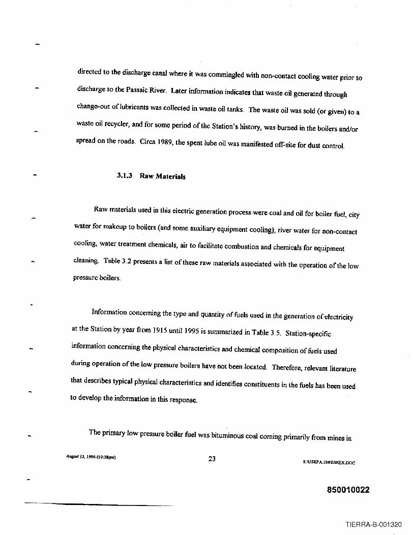
directed to the discharge canal where it was commingled with non-contact cooling water prior to
discharge to the Passaic River. Later infonnation indicates that waste oil generated through
change-out oflubricants was collected in waste oil tanks. The waste oil was sold (or given) to a
waste oil recycler, and for some period of the Station's history, was burned in the boilers andlor
spread on the roads. Circa 1989, the spent lube oil was manifested off-site for dust control.
3.1.3 Raw Materials
Raw materials used in this electric generation process·were coal and oil for boiler fuel, city
water for makeup to boilers (and some auxiliary equipment cooling), river water for non-contact
cooling, water treatment chemicals, air to facilitate combustion and chemicals for equipment
cleaning. Table 3.2 presents a list of these raw materials associated with the operation of the low
pressure boilers.
Information concerning the type and quantity of fuels used in the generation of electricity
at the Station by year from 1915 until 1995 is summarized in Table 3.5. Station-specific
information concerning the physical characteristics and chemical composition of fuels used
during operation of the low pressure boilers have not been located. Therefore, relevant literature
that describes typical physical characteristics and identifies constituents in the fuels bas been used
to develop tbe information in this response.
The primary low pressure boiler fuel was bituminous coal coming primarily from mines in
Avawt 13, 1996 (I0:31pm) 23 8:IUSEPAI04\ESSEX.DQC
850010022
TIERRA-B-001320

West Virginia and Pennsylvania. Coal was delivered by barge and stored both in the yard and in
a coal bunker house. Coal was crushed in a Bradford breaker to a nominal size oftwo inches or
less prior to introduction in the boilers. Tables 3.6 through 3.9 provide a list of the typical
properties and constituents of bituminous coal. Only those constituents identified on the
Comprehensive Environmental Response Compensation and Liability Act ("CERCLA")
hazardous substance list as a hazardous substance are identified.
Fuel oil used in these boilers in later years was No.6 Fuel Oil. Fuel oil was delivered by
barge, stored on site in above-ground tanks and delivered to. the boilers by an intra-faciltiy
pipeline. No.6 Fuel Oil is not listed on CERCLA's hazardous substance list as a hazardous
substance. Table 3.10 presents a list of the properties of No. 6 Fuel Oil and Table 3.11 identifies
constituents in oil that have been listed on the CERCLA hazardous substance list as hazardous
substances.
Chemicals were used in the low pressure boilers to maintain proper water chemistry. (See
Section 3. 1.2.1). The list of these chemicals is presented in Table 3.2. Low concentrations of
these treatment chemicals were used to maintain the boiler chemistry within given limits. Typical
low pressure boiler water chemistry limits obtained from relevant literature are presented in
Table 3.3, which are consistent with prevailing industry practice at the time.
Chemicals were used in the low pressure boiler to clean condenser tubes. The list of
these chemicals is presented in Table 3.2. NEP-22 identified in Table 3.2 was used as an
AugusI13. 19% (IO:3Bpm) 24 S:IUSEPA.I04\ESSEX.!XX:
850010023
TIERRA-B-001321

additive to hydrochloric acid to inhibit Or reduce the aggressiveness of the acid when used in
boiler or condenser c1~nings. Station records arid/or data from relevant literature concerning
the composition ofNEP-22 is not available. Oakite (trisodium phosphate) also identified in
Table 3.2 was used as a surfactant and an alkalizer in the cleaning process.
Chlorine was used as a biocide to treat the non-contact river cooling water.
3.1.4 Products
Electric power was the only product generated at this facility. Table 3.5 provides a listing
by year from 1915 to 1924 and from 1938 through 1995 of the electric power generated at
Essex. Records of the annual. production of electricity produced during the years of 1925
through 1937 are unavailable. Annual production for these years has been estimated based on
electric power generation in 1923 and ]924, when the first phase of Station construction was
completed.
3.1.5 By-Products
The coal used in the low pressure stoker boilers prior to 1949 was of a coarse size, two
inches or less, and was fed into the boilers at the bottom of the furnace. Burning of coal as a fuel
in the low pressure boilers resulted in the production of coal bottom ash. The ash produced was
gravity fed along the slope of the stokers into a rotating clinker grinder, where the hot ash was
A....... 13, 1996 (lO:3Spm) 25S:IUSEPA.ICM\J'.SSEX.DOC
850010024
TIERRA-B-001322

quenched with river water, fragmented, crushed and then gravity fed into an ash hopper. The ash
was transported via the hopper to a small hand-pushed rail car which transported the ash and
water to an ash pit. The ash pit was wood-lined on four sides. The dock side was reinforced by
a concrete retaining wall. The bottom ash material deposited in the pit settled out of the water to
the bottom of the pit. The water which accumulated in the ash pit was decanted via a pipe and
discharged to the Passaic River. Given that water was used solely for quenching (cooling and
fragmentation), it is believed that the volume of water transferred to the ash pit via the hand-
pushed rail cars was not substantiaL
The settled ash was subsequently removed from the ash pit by a mobile crane and
transported off-site for sale or use as fill material. Company records indicate that revenues were
derived from the sale of coal ash from 1950 through ]966. While Company documentation for
the pre-) 950 period has not been located, it is believed that a market for coal ash existed during
the pre-] 950 period.
Relevant literature indicates that the average ash percentage in West Virginia and
Pennsylvania coal was approximately 10% (Table 3.6). This literature also indicates that the
underfeed low pressure stoker boilers were capable of capturing 85% of this coal ash as bottom
ash. Station-specific information concerning the chemical composition of bottom ash and fly ash
have not been located. Compounds identified on the CERCLA hazardous substance list as
hazardous substances have been identified in Pennsylvania and West Virginia coal ash, but at
trace levels. (See Tables 3. 12 - 3.15.)
Auguol 13. 1996 (I0:38P11l) 26S;\USEPA 104\ESSEX.DOC
850010025
TIERRA-B-001323

Station-specific information concerning the chemical composition of the water overflow
from the ash pit is not available. Typical trace chemical constituents listed on the CERCLA
hazardous substance list as hazardous substances for ash pit overflow water have, however, been
located in relevant literature (Tables 3.16 and 3.17). Relevant literature concerning organic
substances are not available for sluice water and ash pit water overflow. As indicated above,
relevant literature does indicate that bottom ash contains very low and/or non-detectable levels
of organic substances (See Table 3.] 4). Therefore water overflow from the ash pit would
contain even lower levels of such substances.
Burning oil as a fuel in the low pressure boilers also resulted in the production of ash. The
ash produced was predominantly (98%) fly ash. Neither Station-specific nor relevant literature
concerning the chemical composition of the NO.6 Fuel Oil ash have been located. No.6 Fuel Oil
however contains lower levels of ash than coal, usually in the range of 0.01 percent to 0.5
percent (Table 3.10). Accordingly, ash emissions from No.6 fuel oil would have been
significantly less than ash emissions when firing coal in the boilers.
A residual not captured in the steam electric generation process is the flue gas
resulting from fuel combustion. This residual is released via the boiler stack to the atmosphere.
The composition of the flue gas emitted varies dependent upon the fuel fired, the equipment
design and the level of emission control. Station specific data on emission characteristics are not
available. The EPRI PISCES Database and other relevant literature provide information on the
identity of the trace constituents in the flue gas from boilers fired by either coal, oil or natural gas
A\I&UI13, 1996 (l0:3Ipm) 27S:\USEP AI04\ESSEX.DOC
850010026
TIERRA-B-001324

which have been identified by EPA under the Clean Air Act Amendments as hazardous air
pollutants. This databa'se also presents emission factors for these trace constituents, Attachment
Iprovides the list of these trace constituents and their associated emission factors.
3.1.6 Maintenance Processes
3.1.6.1 Boiler Cleanings
The generation of steam in the boilers caused minerals originally contained in boiler
feedwater and city water makeup to settle out in the boiler. While certain quantities of minerals
collected in the boiler, some would form scale deposits on the inner walls of the boiler tubes.
The dissolved oxygen remaining in the boiler water would also react with boiler tube material,
forming a thin corrosion layer on the inner sulface of the boiler tubes. The presence of the
corrosion products and mineral scale deposits decreased the heat transfer efficiency of the boiler
tubes. Periodic removal of the corrosion products and mineral scale deposits was required to
maintain boiler heat transfer efficiency. The tubes were cleaned by a mechanical process which
involved the use of small rotating scrapers, referred to as turbines, which were driven through
each tube with water pressure. Station records are not available on the frequency of the
mechanical c1eanings; however, it is believed, based on prevailing industry practice, that this type
of cleaning would have been done on average once per year. The tube cleaning residues were
collected at the lower header of the boiler, where the residues were directed by water to a floor
drain which was connected to the Station Sewer System. The residues were then directed to the
August 13, 1996 (]O;Jlpm) 28S;IUSEP A.I 04\ESSEX.DOC
850010027
TIERRA-B-001325

discharge canal, where they were commingled with the non-contact cooling water and discharged
to the Passaic River. Station records are also not available on the chemical composition ofthe
boiler scale, but it is believed that the principal constituents in the boiler scale would have
included metal oxides of copper and zinc. Small amounts of these oxides would be expected in
the discharge that was commingled with the non-contact cooling waters in the discharge canal.
3.1.6.2 Fireside Cleaning
Boiler maintenance procedures also included the periodic removal of combustion soot
deposited on the exterior of the boiler tubes in the furnace. This soot was removed with the use
of air and stearn lances with the boiler out of service. Force draft fans at low operating speed
were used to move the soot from the furnace chamber to the flue duct. The soot was exhausted
to the atmosphere. Some of the heavier soot would have settled in the base of the boiler stack
which was periodically cleaned. These materials would have been deposited in the ash pit.
Station records concerning the chemical composition of the soot are not available. It is believed,
however, that the chemical composition would be similar to that of fly ash.
Circa 1933, the Station began the use of No. 6 Fuel Oil in some of its boilers. An ash
residue from combustion of the fuel would build up on the exterior of the boiler tubes. Over
time, this ash residue would have reduced heat transfer within the boiler. The boiler was
periodically taken out of service and the exterior of the boiler tubes was washed with high
pressure city water. The water and the combustion ash residue (carbon black) were flushed to
August 13, 1996 (lO:38pm) 29S:IUSEPAI04\ESSEX.DOc
850010028
TIERRA-B-001326

the bottom of the furnace. The residual would either have passed through a floor drain to the
Station Sewer System for discharge to the Passaic River via the discharge canal or have been
collected and commingled with other ash in the ash pit. The chemical composition of the ash
removed in the washwater is believed to be similar to the ash composition of No. 6 Fuel Oil, the
composition of which has not been identified.
3.1.6.3 Condenser Chemical Cleanings
The use of river water for cooling caused biofouling and the deposition of a corrosion
scale on the internal condenser tube surfaces. AJthough injection of chlorine into the river
cooling water substantially reduced biofouling, corrosion scale remained an operating problem.
During the early years of operation, the internal tube surfaces were cleaned manually by brushes
and the inlet and outlet water boxes and tube sheets were manually scraped. The residuals
removed during the manual cleanings were primarily organic materials which would have been
handled as trash.
Available Station records indicate that the turbine/generator was out of service for
approximately 250 hours per year as a result of these cleanings. This cleaning operation required
the turbine/generator to be taken out of service because the low pressure turbine/generators were
provided with a single condenser per turbine. The flooded capacity of the waterside of the
condensers was 7,800 to 15,500 gallons depending on the condenser.
Augusl 13, J 996 (I0:38pm) 30 S:\USEPA.l04IESSDC.DOC
850010029
TIERRA-B-001327

Later, the Station conducted chemical cleaning of the condenser to remove scales and
biofouling materials. Station records concerning the frequency and procedures for chemical
c1eanings prior to 1945 have not been located. Station records have been located, however, with
respect to the frequency and method associated with chemical c1eanings from 1945 until the
Station's steam boilers were taken out of service in the mid to late 1970s. Available information
indicates that a total oftwenty+four chemical c1eanings were perfonned on the waterside of the
low pressure condensers during the operating history of the Station. Table 3.18 presents a list of
c1eanings and relevant details concerning each of these c1eanings.
The methods utilized in each of these cleanings was generally the same. A chemical
cleaning solution was prepared in a chemical mix tank consisting of water, hydrochloric acid
("HellO) and NEP-22. NEP-22 was used as an inhibitor to reduce the dissolution rate of the base
metals by the hydrochloric acid. Station records indicate that the solution was prepared and
maintained at a concentration ranging from 2% to 5% ofHCl. After isolating the condenser, the
cleaning solution was pumped into the condenser and recirculated in the condenser tubes for one
to two hours. Given that the flooded capacity of the water side of the condensers ranged from
7,800 to 15,500 gallons, an equivalent volume of spent cleaning solution may have been drained
directly to the discharge canal where it was commingled with the non-contact cooling water.
Considering the flow of the non-contact cooling water in the canal, spent solution would have
been diluted by approximately 25 to I if discharged over a period of one minute. River water
was used to flush any residual material in the waterside of the condenser. Station records as to
the chemical composition of the discharge have not been located. A search of relevant literature
AlIglUI 13, 1996 (lO:3Ipm) 31 S:\USEPA 104IESSF.X.DOC
850010030
TIERRA-B-001328

fails to identify typical chemical composition data. The discharge to the Passaic River would,
however, have contained biological materials (e.g., barnacles), certain metals (e.g., copper and
zinc), and a dilute Hel solution.
3.2 Unit No.7 High Pressure Turbine/Generator and Nos. 2S and 26 HigbPressure Boilers
This section presents a discussion of the electric generation process and auxiliary
processes involved with the generation of electricity using high pressure turbine/generators and
boilers. A process flow diagram has been provided as Figure 3.2.
3.2.1 Process Description
Eight of the low pressure boilers were demolished in 1937 and two high pressure
pulverized coal fired boilers (Nos. 25 & 26) and one high pressure non-condensing
turbine/generator (Unit No.7) were installed. Electric power was generated using the same
processes used to generate electric power in the low pressure process. A detailed list of
operating parameters of this equipment is provided in Table 3.19.
Boilers Nos. 25 and 26 generated steam at a higher pressure (1250 psi) and a higher
temperature (950"F). The steam was fed to a new, high pressure turbine/generator which rotated
at a rate of3600 RPM. Exhaust steam at a pressure of225 psi from the high pressure turbine
was piped to the existing low pressure turbine/generators rather than to condensers, as in the low
August 13, 1996 (I0:3 I pm) 32 S~USEPA.I04IJ:.SSEX.DOC
850010031
TIERRA-B-001329

pressure system design. The volume/mass aflow pressure steam exhausted from the new high
pressure turbine effectively replaced the volume/mass of low pressure steam for generation
previously produced by the eight low pressure boilers removed from service. The stearn was
exhausted from the low pressure turbines to the low pressure condensers where it formed
condensate. The condensate was pumped to a surge tank where it was combined with
condensates from the other low pressure boilers for reuse in the generation of steam. A portion
of this water was also pumped to a condensate storage tank for use as a makeup water source
for the high pressure units.
Boilers Nos. 25 and 26 were more efficient than the low pressure boilers for a number of
reasons, which may be summarized as follows:
• Fuel Preparation: The coal type used in these boilers was the same as that used in the
low pressure boilers, but the preparation process was improved. The coal was pulverized
and reduced to a fine powder which was blown into the boilers with air from the forced
draft fan duct. By using pulverized coal, more of the surface area of the fuel was exposed
to the oxygen in the air during the combustion process. The pulverized coal was blown
through the burners and exited the burner tips where it mixed with air from the forced
draft fan in the furnace. This resulted in an increase in the rate at which fuel was heated.
resulting in an increase in the boiler combustion temperature by several hundred degrees .
• Boiler Design: Two changes in boiler design improved boiler heat transfer efficiency.
August B, 1996 (l0:38pm) 33 S:\USEPA.l04IESSEX.DOC
850010032
TIERRA-B-001330

The boiler tubes were designed with a smaller diameter, thereby providing more heat
transfer surface per unit volume of water. In addition, boiler waterside tubes were
installed along the walls and floors of the furnace, increasing the volume of water heated
per unit of furnace volume .
• Economizers and Superheaters: Boilers Nos. 2S and 26 contained an economizer and a
superheater which are heat recovery equipment. Boiler water preheated by feedwater
heaters was routed to the economizer for further preheating prior to circulation through
the boiler drum and the furnace boiler tubes. Heated water from the boiler tubes was then
circulated to a drum where it separated into water and saturated stearn phases. The
saturated steam was piped to the superheater section of the boilers where the temperature
of the steam was raised to 950°F at a pressure of 1250 psi. This section of the boiler
utilized waste flue gases (heated combustion gas) as a heat source, which in the lower
pressure boiler had been exhausted out the stack. This use of heat recovery equipment
resulted in greater boiler thermal efficiency .
• Air Preheaters: Boilers Nos. 25 and 26 were equipped with air preheaters. Air
preheaters are sections of metal plates, called baskets, fitted into a circular form which are
rotated at a point between the exhaust duct and the air inlet duct. When the baskets were
in the exhaust duct, they received heat from the flue gases exhausted from the boiler. This
waste heat would raise the temperature of the metal plates in the air heater baskets. As
the baskets rotated out of the flue gas area and into the air inlet duct, the heat stored in the
Augusl13, 1996 (10:npm) 34 S:\USEPA,l04IESSEX.DOC
850010033
TIERRA-B-001331

metal plates would have been released (transferred) into the incoming air for use in the
combustion process. As was the case with the superheater and economizer. the air heaters
utilized as a heat source what had previously been waste flue gases in the low pressure
boilers. The use of air heaters to pre-heat the combustion air to the boiler also increased
the overall Station thermal efficiency .
• Feedwater Heaters: Boilers Nos. 2S and 26 were equipped with feedwater heaters, which
used extracted (bleed) steam from the turbines to pre-heat boiler feedwater. Preheating of
the boiler water increased the overall thermal efficiency of the Station by reducing the
amount offuel required to generate a unit value of electricity.
• Electrostatic Precipitators: Boilers Nos. 2S and 26 were equipped with electrostatic
precipitators ("ESPs") collected fly ash particles from the exhaust flue gases, thus reducing
particulate emissions associated with the generation of fly ash. Collected fly ash from the
precipitators was fed to stationary hoppers and then piped to the bottom ash collection pit
in the bottom of the boiler.
3.2.2 Auxiliary Process
3.2.2.1 Boiler Water
Boiler water for operation of the high pressure boilers was supplied by condensate from
Auguot 13, 1996 (IO:3lpm) 35 S:\USEPA.I04\£SSEX.DOC
850010034
TIERRA-B-001332

the condensate storage tank that was fed from the low pressure boiler system. Condensate from
this source had been chemically treated, deaerated and distilled in the low pressure boiler system
process. This condensate was gravity fed from the condensate storage tank to the high pressure
boilers by way of a feed water deaerator, which preheated the condensate. The deaerator was a
more efficient design compared to the low pressure boiler system open heaters.
Sodium sulfite was added to the feed water at the deaerator to remove dissolved oxygen.
Trisodium phosphate was also fed to the deaerator to establish and maintain a boiler water pH
low enough to prevent caustic embrittlement of boiler tubes .. Typical high pressure boiler water
chemistry limits employ~d by the Station are presented in Table 3.21. These limits were
consistent with industry practice at the time. The water was gravity fed to tbe condensate
pumps, which pumped tbe condensate through the low pressure feedwater beater for further
preheating. The water was then directed to the boiler feed pumps, then through a high pressure
feed water heater before entering the boiler. Minerals in the water (boiler feed) collected in the
boiler drum. The quantity of minerals in the IUghpressure boiler water was considerably less
than in the low pressure boiler water because of the use of the pure condensate from the lower
pressure boiler system for makeup. This reduced the amount of boiler chemicals required.
Blowdown was conducted on a continuous basis at a rate of 10 to 20 gpm. The boiler
blowdown was collected and routed to a drain tank, and then to the open heaters for preheating
and reuse in the generation of steam in the low pressure boilers.
3.2.2.2 Non-Contact Cooling
August 13, 1996 (lO:38pm) 36 S:IUSEP A.1G4\ESSEX.DOC
850010035
TIERRA-B-001333

As discussed above, the high pressure turbine/generator (Unit No.7) that was installed
with the two high pressure boilers (Nos. 25 & 26) was a topping, non-condensing turbine. There
was no condenser for Unit No. 7 and therefore no non-contact cooling water was required for
the system. The stearn exhausted from Unit NO.7 was routed to the low pressure turbines to
generate electricity. This steam, when exhausted from the low pressure turbines, was then
routed to the existing low pressure condensers for condensing. The condensate was then routed
to the condensate tank for reuse in the steam generation process.
Lubricating oils were used to cool and lubricate rotating equipment, such as the boiler
feed pumps and the tur~ine shaft load-bearing surfaces. The lubricating oils were in a closed
looped system and accordingly, once heated the lubricating oils needed to be cooled for reuse.
Non*contact river cooling water was pumped through small tubed heat exchangers where the
river water cooled the lubricating oils. Heat exchanger design and operation were similar to that
of the condensers.
3.2.2.3 Equipment Lubrication
Station moving equipment required lubrication. Lube oil was heated as it flowed past the
rotating bearing surface and was then cooled with non-contact river cooling water for reuse.
The turbine lube oil system included equipment which would filter and/or separate solid particles
(sludge) contained in the lube oil. The lube oil was reused until its lubricating properties were
spent (i.e., the viscosity of the oil was diminished). An early Station print (dated 1917) indicates
Auaust 13, 19% (I 0:38pm) 37 S;\USEPAI04IESSEX.DOC
850010036
TIERRA-B-001334

that water and sludge drains from lube oil filters, and drains from a lube oil storage tank were
directed to the discharge cana! where it was commingled with non-contact cooling water prior to
discharge to the Passaic River. Later information indicates that waste oil generated through
change-out of lubricants was collected in waste oil tanks. The waste oil was sold (or given) to a
waste oil recycler, and for some period of the Station's history, was burned in the boilers and/or
spread on the roads. Circa 1989, the spent lube oil was manifested off-site for dust control.
3.2.3 Raw Materials
Raw materia!s used in this electric generation process were coal and oil for boiler fuel, city
water for some auxiliary equipment cooling, boiler water treatment chemicals, air to facilitate
combustion and chemicals for equipment cleaning. Table 3.20 presents a list of these raw
materials.
Information concerning the type and quantity of fuels used in the generation of electricity
at the Station by year from 1915 through 1995 is summarized in Table 3.5. Station-specific
information concerning the physical characteristics and chemical composition of fuels used
during operation of these high pressure boilers has not been located.
The coal used at the Station was bituminous coal coming primarily from mines in West
Virginia and Pennsylvania. Coal for these units was delivered to and managed by the Station in
the same manner as the coal for the low pressure boilers. Coal was crushed in a Bradford
Augusl13, 1996 (JO:3Ipm) 38 S:\USEPA.l04IESSEX.DOC
850010037
TIERRA-B-001335

breaker to a nominal size of two inches or less. After crushing, the coal was delivered to the
pulverizers and reduced to a fine powder. This coal powder was then blown in the boilers with
air through specially designed burners. Table 3.6 presents the typical chemical composition of
these coals and Tables 3.7 through 3.9 list the constituents of these coals that are on the
CERCLA hazardous substance list as hazardous substances.
In later years, the fuel oil used in these boilers, was NO.6 Fuel Oil. Fuel oil was delivered
by barge, stored on site in above~ground tanks and delivered to the boilers by pipeline. Tables
3.10 and 3.11 present a list of the properties of the oil and constituents of No. 6 Fuel Oil that are
on the CERCLA hazardous substance list as hazardous substances.
Chemicals were used in the high pressure boilers to maintain proper boiler water
chemistry. The list of these chemicals is presented in Table 3.20. Low concentrations of these
treatment chemicals were used to maintain the boiler chemistry within given limits. Typical high
pressure boiler water chemistry limits employed by the Station are presented in Table 3.21.
These limits were consistent with industry practice at the time.
Chemicals were used to clean boiler tubes and feedwater heaters. A list of these chemicals
is presented in Tables 3.22 and 3.23 respectively.
3.2.4 Products
Augud 13. 1996 (lO:3apm) 39 S:\USEPA,1 O4IF.SSEX.DOC
850010038
TIERRA-B-001336

Electric power was the only product produced at this facility. Table 3.5 provides a listing
by year from 1915 to 1924 and from 1938 through 1995 of the electric power generated at
Essex. Documentation of the annual production of electricity produced during the years of 1925
through 1937 is unavailable. Annual production for these years has been estimated based on
electric power generation and fuel usage in 1923 and 1924 when the first phase of Station
construction was completed.
3.2.5 By-Products
The use of pulverized coal changed the type of ash generated from primarily bottom ash or
cinders to primarily a fly ash. The fly ash suspended in the combustion gases would move
through the boiler to the stack where it would be collected in ESPs. Relevant literature indicates
that these ESPs were very efficient (i.e. 90%) in removing fly ash from the flue gas. Fly ash
collected by the ESPs dropped into stationary hoppers and was piped to a slag tank pit at the
bottom of the boiler, mixed with the bottom ash and sluiced via a concrete lined sluice trench to
the ash pit. The bottom ash was collected on the floor of the furnace as a molten slag and flowed
over a water-cooled dam into a slag tank pit where it was quenched with river water. The
resultant sluice was gravity fed to the sluice trench. and transported to the ash pit.
The ash handling system was modified in 1947, coincident with the construction of New
Unit No.1. The bottom ash was collected on the floor of the furnace as a molten slag, which
flowed over a water-cooled dam into a slag tank where it was quenched with river water. The
Augual 13, 1996 (lO:38pm) 40 S:\USEPA.I04IESSEX.DOC
850010039
TIERRA-B-001337
resultant sluice was pumped to an ash lake, where solids were settled out and the sluice water
was decanted to the Passaic River by means of an overflow box and discharge pipe.
The ash produced was generally collected by material handling equipment on the property
for sale or other off-site disposition such as for fill. Company records indicate that revenues
were derived from the sale of this coal ash from 1950 through 1966. Although documentation
for the pre-1950s is not available, it is believed that a market for coal ash existed during the pre-
1950 period.
Relevant literatu~e indicates that the average ash percentage in West Virginia and
Pennsylvania coal was approximately 10% (Table 3.6). Station-specific information concerning
the chemical composition of bottom ash and fly ash is not available. Tables 3.12 through 3.15
identitY the constituents in the bottom and fly ashes from these coals which are on the CERCLA
hazardous substance list as hazardous substances.
Station-specific information concerning the chemical composition of the water overflow
from the ash pit is not available. Tables 3.16 and 3.17 identify the constituents that may have
been in the sluice water and overflow from the ash pit which are on the CERCLA hazardous
substance list as hazardous substances. Relevant literature concerning organic substances are not
available for sluice water and water overflow. As indicated above, relevant literature does
indicate that bottom ash contains very low and/or non-detectable levels of organic substances.
(See Table 3.14). Therefore, sluice water and water overflow from the ash pit/pond would
AU£IISI13, 19% (10:3&pm) 41 S:\USEP A. 104\ESSEX.DOC
850010040
TIERRA-B-001338

contain even lower levels of such substances.
Burning of oil as a fuel also resulted in the production of ash, predominantly fly ash
(98%). Station specific information concerning the chemical composition offuel oil bottom and
fly ash is not available. Fuel oil typically contains only 0.01-0.5% by weight ash (Table 3.10).
A residual not captured in the steam electric generation process is the flue gas
resulting from fuel combustion. This residual is released via the boiler stack to the atmosphere.
The composition of the flue gas emitted varies dependent upon the fuel fired, the equipment
design and the level of emission control, Station specific data on emission characteristics are not
available. The EPRI PISCES Database and other relevant literature provide information on the
identity of the trace constituents in the flue gas from boilers fired by either coal, oil or natural gas
which have been identified by EP A under the Clean Air Act Amendments as hazardous air
pollutants. This database also presents emission factors for these trace constituents. Attachment
I provides the list of these trace constituents and their associated emission factors.
3.2.6 Maintenance Processes
3.2.6.1 Boiler Cleanings
Periodic removal of corrosion and scale on the interior of the boiler tubes was required to
maintain boiler heat transfer efficiency. The tubes in the high pressure boilers were more
AugustlJ, 1996 (IO:JRprn) 42 S:IUSEP A.I04\ESSE.X.DOC
850010041
TIERRA-B-001339

numerous and smaller in diameter than in the low pressure boilers, making the cleaning of the
tube surfaces using mechanical methods impossible. A cleaning process using chemicals was
necessary. Chemical cleaning of the boilers generally involved the cleaning of only the waterside
boiler tubes and drums. The maximum flooded capacity of these boiler components was 13,000
gallons. The economizers were generally not chemically cleaned. The superheaters were not
cleaned.
-Available information indicates that the waterside of each of the two high pressure boilers
(Nos. 25 and 26) was chemically cleaned twenty-three times: A chemical solution ofHCI and
NEP-22 was used in thy first twenty-one c1eanings. The solution was prepared and maintained at
a concentration ranging from 1% to 5% HCl. The twenty· first cleaning of each boiler was done
using Vertan 675 (tetra ammonium ethylene diamine tetra acetic acid). The twenty-second
cleaning for each boiler was done using Citrosolv, an ammoniated citric acid. Table 3.22 lists the
c1eanings and presents details associated with each cleaning.
For the cleanings which used inhibited HCl, the boiler tubes were drained. Chemical
solutions were mixed with water in a chemical cleaning tank and the resultant solution was
pumped into the boiler waterside and circulated through the boiler water tubes. The boiler tubes
were filled once, with the chemical cleaning solution, circulated and drained. The solution was
recirculated to the chemical cleaning tanks for concentration analysis, additional chemicals were
added as required, and then the solution was pumped back to the waterside of the boiler for
recirculation through the boiler tubes. After the boiler tubes were drained, the boiler waterside
Auauol13, 19% (IO:3Ipm} 43 S:\USEPA.I04IESSEX.DOC
850010042
TIERRA-B-001340

was flushed with fresh water. Station records documenting the methods used to handle the spent
cleaning solution or rinse waters from these c1eanings or the chemical composition of the spent
solution or rinse waters have not been located. Prevailing industry practice, however, was to
direct the spent cleaning solution to the discharge canal where it was commingled with the non-
contact cooling water and discharged to the Passaic River. Relevant literature provides typical
compositional makeup of the spent solution and the first rinse drain. The compositional data are
presented in Table 3.24.
Subsequent c1eanings (Nos. 21 and 22) utilized alternate chemical cleaning methods that
improved cleaning efficiency, i.e. iron and copper removal. Vertan 675 or CitroSolv was used in
these c1eanings. The waterside was isolated after introduction of the chemicals. The solution
was circulated through the boiler waterside by periodically beating and cooling the solution. The
spent cleaning solution was either directed to the other boiler (No. 25 if26 were being cleaned
and No. 26 if25 were being cleaned) and evaporated in the furnace of the boiler, or trucked off
site (see Table 3.22). The boiler waterside was flushed with water after the boiler tubes were
drained of solution. Rinse water was drained to the discharge canal where it was commingled
with the non-contact cooling water and discharged to the Passaic River.
3.2.6.2 Chemical Cleaning of Feedwater Heaters
The electric generation process associated with the use of higher pressure boilers (Nos. 25
and 26) utilized feedwater heaters to pre-heat water for steam generation. Feedwaterheaters are
AuguJI13, 1996 (1O:38pm) 44 S:\uSEP A.I04\E.SSEX.DOC
850010043
TIERRA-B-001341

heat exchange devices containing tubing similar to condensers. Station records concerning the
flooded capacity of the waterside and steamside for Units 25 and 26 feedwater heaters are not
available. The capacities, however, would have most likely been similar to the capacities for the
New Unit No. 1 feedwater heaters, i.e. flooded capacity of the waterside of 400 gallons and of
the steamside of approximately 1,500 gallons (See Section 3.3.6.3) .
.As was the case for the boiler tubes, the flow of water in the feedwater heater tubes
created the potential for deposition of corrosion scale and mineral deposits on the inside of the
tubes. This reduced the heat transfer efficiency of the feedwater heaters. Chemical c1eanings
were performed to remove scale and mineral deposits to increase effectiveness of heat transfer.
Available information indicates that fourteen cleanings were performed. Table 3.23 lists
the cleanings and relevant details associated with each of the cleanings.
The method for all of these cleanings was generally the same. A cleaning solution
consisting of water, a chemical cleaning agent and an inhibitor was prepared in the chemical mix
tank. The cleanings were one volume cleanings. Cyanide and, later, HCI were used as the
cleaning agents. The cleaning solution was circulated within the tubes in the feedwater heater.
The tubes were likely rinsed with city water. Station records documenting the discharge of the
spent cleaning solution and rinses have not been located. Prevailing industry practice, however,
was to direct the spent cleaning solution to the discharge canal where it was commingled with
the non-contact cooling water and discharged to the river.
AIIgUIII3, 1996 (!0:31pm) 45 S:\USEPAI04IESSEX.DOC
850010044
TIERRA-B-001342

3.2.6.3 Air Heater Washes
Air heaters were washed with river water to remove ash. dust, and soot from the air heater
baskets to ensure maintenance of heat transfer efficiency. The air heaters were cleaned one to
two times each year. The washwater was directed to the ash sluiceway and routed to the ash pit
until 1947, when it was routed to the ash lake. Circa 1970. when the ash lake was removed, the
wash water was rerouted to the chemical waste basin (See Section 4.1.5).
3.2.6.4 Fireside Wash
When firing NO.6 Fuel Oil, combustion ash residues (e.g .• soot) would build up on the
exterior of the boiler tubes. Over time. this residue would reduce heat transfer within the boiler.
The boiler was periodically taken out of service and the exterior of the boiler tubes was washed
with high pressure city water.
The water and combustion ash residues were flushed to the bottom ofthe furnace. The
residual was drained to a floor drain, directed to the discharge canal, commingled with the oon-
contact cooling water, and discharged to the Passaic River.
3.3 High Pressure Unit No.1
This section presents a discussion of the electric generation process and auxiliary
Auguol13, 1996 (I0:31pm) 46 S:\USEP A,104\ESSEX.DOC
850010045
TIERRA-B-001343

processes involved with the generation of electricity using a unitized high pressure boiler and
multi-stage turbine/ generator. A process flow diagram is depicted in Figure 3.3. The boiler and
turbine/generator are tied together in a unitized system, and are independent from the rest of the
generating Station equipment.
3.3.1 Process Description
Circa 1946, four low pressure boilers and one low pressure turbine/generator (original
Unit No.1) were removed from service. One high pressure boiler with one high pressure tandem
compound double-flow turbine/generator ("New Unit No. I") was installed. The boiler supplied
steam only to the New Unit No. 1 high pressure turbine. The New Unit No. 1 boiler was
designed to burn coal, oil or gas. All three fuels were used interchangeably in this unit depending
on a myriad of factors including fuel cost and availability.
Electric power was produced in this unit in a manner similar to that in the other Station
electric generation processes described in Sections 3.1 and 3.2. While physically larger, the
boiler design included a number of the same component equipment as high pressure boiler Nos.
25 & 26 (i.e., furnace with wall and floor tubes, economizer and superheater sections. feedwater
heaters, air pre-heaters, pulverizers, and electrostatic precipitators). The boiler design
incorporated a more sophisticated feedwater heating system and boiler tubes that were even
smaller in diameter than the tubes in Nos. 25 and 26 boiler. Again, as with the design of Nos. 25
and 26 boilers, the design was focused on the capture for reuse of water and waste energy.
AIlflII"l13, 1996 (lO:38pm) 47 S~USEPA.l04\ESSEX.DOC
850010046
TIERRA-B-001344

thereby increasing the net Station thennal efficiency.
The boiler generated steam at a pressure of 1265 psi at a temperature of 1000°F. The
turbine/generator shaft rotated at a rate of 3600 rpm. Exhaust steam was directed to a dedicated
condenser where the steam was condensed to water. The waterside flooded capacity of this
condenser was 17,460 gallons. Condensate was collected in a hotwell and gravity fed to
condensate pumps. The hotwell operated under a vacuum and served a function similar to that
of the deaerator removing oxygen from the condensate. The condensate was pumped through a
condensate cooler (containing water-filled tubes) for further cooling using river water as the non-
contact coolant The c,?oled condensate water was then pumped to generator coolers and other
miscellaneous coolers for use as a coolant for auxiliary equipment. This was the first stage for
the preheating of the condensate water for reuse as boiler feedwater. The feedwater to the boiler
was then routed through a series of feedwater heaters for further preheating prior to being routed
to the boiler for steam generation. The heat source for the feedwater heaters was steam,
extracted from various stages of the turbine exhaust This steam was re-routed to the hotweU as
a condensate after passing through the feedwater heaters, and subsequently re-circulated through
the feedwater heaters and back to the boiler for steam generation.
The unit had an ESP which captured the fly ash. When coal was used as the boiler fuel,
fly ash captured by the ESP was returned to the furnace and fired. This significantly reduced the
volume of fly ash and improved overall Station thermal efficiency. Fly ash returned to the boiler
would increase the quantity of bottom ash.
AuguIt 13, 1996 (lO:3Bpm) 48 S:IUSEPA.l04\ESSEX.DOC
850010047
TIERRA-B-001345

3.3.2 Auxiliary Processes
3.3.2.1 Boiler Water
Water used to generate stearn in New Unit No. I boiler was supplied by condensates from
the existing low pressure boilers. The condensate had been chemically treated, deaerated and
distilled in the low pressure boilers. This condensate was gravity fed from the condensate
storage tank where it had been collected from the low pressure system, and pumped to a hotwell.
The hotwell replaced the function performed by the deaerator used in Boilers No. 25 and 26.
The water was then rou,ted to the condensate cooler for cooling and then circulated through the
condensate and feed water system for use in the boiler for steam generation. Sodium sulfite
solution was pumped into the feed water to the boiler drum to remove any residual oxygen.
Trisodium phosphate solution was pumped to the boiler drum to maintain pH between 10.5 and
10.8. Typical boiler chemistry limits are provided in Table 3,27. These limits are consistent with
prevailing industry practice at the time. Boiler blowdown was conducted on a continuous basis
at a rate of 10 to 20 gpm, piped to a drain tank and routed to the low pressure boiler open
heaters. The open heaters fed condensatelblowdown to the existing low pressure boilers for
reuse in the generation of steam, as the quality of the high pressure boiler blowdown was better
than that of city water. Overflow from the drain tank was routed to the Passaic River.
3.3.2.2 Non-Contact Cooling
Auguol13, 19% (IO:3Ipm) 49 S:IUSEPA.I04\ESSEX.DOC
850010048
TIERRA-B-001346

New Unit No. 1 was equipped with one condenser. The non-contact cooling process
exhausted steam for New Unit No. 1 was the same process utilized for non-contact cooling of
exhausted steam in the low pressure system. In connection with the installation of this unit, the
cooling water intake system was upgraded, increasing the non-contact cooling water flow design
capacity to 430,500 gpm.
Lubricating oils were used to cool and lubricate rotating equipment, such as the boiler
feed pumps and the turbine shaft load-bearing surfaces. The heated lubricating oils needed to be
cooled for reuse. River cooling water was pumped through small tubed heat exchangers where
the river water cooled the lubricating oils. Heat exchanger design and operation were similar to
that of the condensers. The cooled lubricating oils were reused in a closed cycle for equipment
lubrication and cooling.
3.3.2.3 Equipment Lubrication
Station moving equipment required lubrication. Lube oil was heated as it flowed past the
rotating bearing surface and was then cooled with non-contact river cooling water for reuse.
The turbine lube oil system included equipment which would filter and/or separate solid particles
(sludge) contained in the lube oil. The lube oil was reused until its lubricating properties were
spent (i.e., the viscosity of the oil was diminished). An early Station print (dated 1917) indicates
that water and sludge drains from lube oil filters, and drains from a lube oil storage tank were
directed to the discharge canal where it was commingled with non-contact cooling water prior to
August 13, 1996 (lO:3Ipm) 50 S:\USE.P A-104\ESSEX.DOC
850010049
TIERRA-B-001347

discharge to the Passaic River. Later jnformation indicates that waste oil generated through
change-out oflubricants was collected in waste oil tanks. The waste oil was sold (or given) to a
. waste oil recycler, and for some period of the Station's history, was burned in the boilers and/or
spread on the roads. Circa 1989, the spent lube oil was manifested off-site for dust control.
3.3.3 Raw Materials
Raw materials used in this electric generation process were coal, oil, or gas for boiler fuel,
city water for some auxiliary equipment cooling, river water for non-contact cooling, boiler
water treatment chemic!lls, air to facilitate combustion and chemicals for equipment cleaning.
Table 3.25 presents a list of these raw materials.
Information concerning the type and quantity offuels used in the generation of electricity
at the Station by year from 1915 through 1995 is summarized in Table 3.5. Station-specific
information concerning the physical characteristics and chemical composition of materials used
during operation of the high pressure boilers is unavailable.
The coal was bituminous coal primarily from mines in West Virginia and Pennsylvania.
Coal was crushed in a Bradford breaker to a nominal size of two inches or less. After crushing,
the coal was delivered to the pulverizer and reduced to a fine powder. This coal powder was
then blown in the boiler with air through specially designed burners. Table 3.6 presents a list of
the chemical properties of these coals and Tables 3.7 through 3.9 identifies those constituents
AuguIt 13, 1996 (lO:3Ipm) 51 S:lUSEPA.I04\ESSEX.DOC
850010050
TIERRA-B-001348
which are on the CERCLA hazardous substance list as a hazardous substance.
The fuel oil used in New Unit No. 1 boiler was NO.6 Fuel Oil. Tables 3.10 and 3.11
present a list of the properties ofthe oil and constituents identified in NO.6 Fuel Oil that are on
the CERCLA hazardous substance list as a hazardous substance. Fuel oil was delivered by
barge, stored on site in above ground storage tanks and delivered to the boilers by pipeline.
Natural gas was also used as a boiler fuel New Unit No.1. Natural gas was fed to the Station
via a high pressure transmission line from Transcontinental Gas Pipe Line Corporation. Table
3.26 presents the typical chemical composition of natural gas.
Chemicals were used in the high pressure boilers to maintain proper water quality. The
list of these chemicals is presented in Table 3.25. Low concentrations of these treatment
chemicals were used to maintain the boiler chemistry within given limits. Typical high pressure
boiler water chemistry limits employed by the Station are presented in Table 3.27. These limits
were consistent with prevailing industry practice at that time.
Chemicals were used to clean the boiler condensers and feedwater heaters. These
chemicals are presented in Table 3.25.
Chlorine was used to treat the non-contact cooling water. Chlorine was stored on-site in
pressurized metal storage containers.
August 13, 1996 (IQ:38pm) 52 S:\USEPA.1Q4IESSEX.DOC
850010051
TIERRA-B-001349

3.3.4 Products
Electric power was the only product generated at this facility. Table 3.5 provides a listing
by year from 1915 to 1924 and from 1938 through 1995 of the electric power generated at
Essex. Station records as to the annual production of electricity during the years of 1925
through 1937 are unavailable. Annual production for these years has been estimated based on
electric power generation in 1923 and 1924, when the first phase of Station construction was
completed.
3.3.5 By~Products
The use of pulverized coal changed the type of ash generated. Similar to Nos. 25 and 26
boilers, the ash produced was primarily fly ash; the balance was bottom ash. The fly ash would
be carried suspended in the combustion gases through the boiler. Fly ash was collected by the
electrostatic precipitator and then gravity fed to stationary hoppers and returned to the boiler for
refiring. Fly ash was introduced back into the furnace through "dust nozzles" for recombustion,
forming additional bottom ash.
The electrostatic precipitators installed at Essex were some of the earliest applications of
this technology. Relevant literature indicates that these emission control systems were very
efficient in removing fly ash from the boiler exhaust gases generally 90% or greater.
AlIgIiIt 13, 1996 (1O:38pm) 53 S:\USEPA. J04IESSEX.DOC
850010052
TIERRA-B-001350

The ash handling system was modified in 1947. coincident with the construction of the
New Unit NO.1. The bottom ash was collected on the floor of the furnace as a molten slag and
flowed through a slag tap into a slag tank where it was quenched with river water. The resultant
ash sluice was then pumped to an ash lake where solids were settled out. Water was decanted to
the River by means of an overflow box and discharge pipe.
Relevant literature indicates that the average ash percentage in West Virginia and
Pennsylvania coal was 10% (Table 3.6). Station-specific information concerning the chemical
composition of bottom ash and fly ash is not available. Tables 3.12 through 3.15 identify the
constituents identified for bottom and fly ash from West Virginia and Pennsylvania coals that are
on the CERCLA hazardous substance list as hazardous substances.
Station-specific information concerning the chemical composition of the water overflow
from the ash lake is not available. Using data available from relevant literature, Tables 3.16 and
3. I7 present the constituents that were believed to be present for this water which are on the
CERCLA hazardous substance list as hazardous substances. Relevant literature concerning
organic substances is not available for sluice water and water overflow. As indicated above,
relevant literature does indicate that bottom ash contains very low and/or non-detectable levels
of organic substances. (Table 3. 14) Therefore, sluice water and water overflow from the ash
lake would contain even lower levels of such substances.
The ash produced was generally collected by material handling equipment on the property
AU&UIII3. 1996 (lO:3Ipm) 54 S:\USEP A.I04\ESSEX.DOC
850010053
TIERRA-B-001351

for sale or other off-site disposition. Company records indicate that revenues were derived from
the sale of this coal ash from 1950 through 1966. Although documentation is not available, it is
believed that a market for coal ash existed during the pre-1950 period.
A residual not captured in the steam electric generation process is the flue gas
resulting from fuel combustion. This residual is released via the boiler stack to the atmosphere.
The composition of the flue gas emitted varies dependent upon the fuel fired, the equipment
design and the level of emission control. Station specific data on emission characteristics are not
available. The EPRI PISCES Database and other relevant literature provide information on the
identity of the trace constituents in the flue gas from boilers fired by either coal, oil or natural gas
which have been identified by EPA under the Clean Air Act Amendments as hazardous air
pollutants. This database also presents emission factors for these trace constituents. Attachment
I provides the list of these trace constituents and their associated emission factors.
3.3.6 Maintenance Processes
3.3.6.1 Boiler Cleanings
Periodic removal of corrosion and scale on the interior of the boiler tubes was required to
maintain boiler heat transfer efficiency. As was the case with high pressure boilers Nos. 25 and
26, the tubes in the high pressure Boiler No. 1 were more numerous and smaller in diameter than
in the low pressure boilers, making the cleaning of the tube surfaces using mechanical methods
August 13, 1996 (10:3Bpm) 55 S:\USEPA.104\ESSEX.DOC
850010054
TIERRA-B-001352

impossible. A cleaning process using chemicals was necessary. Chemical cleaning of the boilers
involved only the cleaning of the waterside boiler tubes, drum and economizer. The flooded
capacity of these components was 40,000 gallons. The superheater was not cleaned.
Available information indicates that this high pressure boiler was chemically cleaned once
prior to commercial operation (see below) and eight times during its operating history. Table
3.28 presents a list of the cleanings performed during New Unit NO.1 Boiler's operating history
and relevant details associated with each of the c1eanings. The chemical cleaning done prior to
commercial operation used different chemicals and procedures than used to perfonn the boiler
c1eanings after commer~ial operations began.
The pre-operational chemical cleaning was perfonned on November 15, 1947 utilizing the
following procedures: an alkaline boil-out using trisodium phosphate, sodium hydroxide and
sodium meta-silicate followed by a rinse; then a conventional acid cleaning using hydrochloric
acid (with an inhibitor); and finally three rinses with condensate water. Available documentation
indicates that the concentration ofHCI in the cleaning solution was 3.8%. The first rinse used
city water and condensate from the low pressure system. Available documentation indicates that
the concentration of HeI in the first rinse was 0.15%. The second rinse used 0.25% caustic soda
and 0.5% trisodium phosphate solution. The third rinse used condensate. Station records
documenting the chemical composition of the spent solution or rinse waters have not been
located.
August 13, 1996 (lO:3Bpm) 56 S;\USEPA.l04IESSEX.DOC
850010055
TIERRA-B-001353

-,
The next six cleanings used HCI and were performed during the period from 1949 to
1958. These acid cleanings were perfonned utilizing methods similar to those used for Boiler
Nos. 25 and 26. In addition, the management of the spent cleaning solution and its chemical
composition would likely have been the same as that for Boiler Nos. 25 and 26 (See Section
3.2.6.1 and Table 3,24).
An eighth cleaning was performed in October 1965 by an outside contractor - Dow
Industrial Services. The cleaning consisted of two stages. The first stage, or "Bromate Stage",
was performed for copper oxide removal and utilized a bromate solution consisting of a total of
3,250 gallons of aqua ammonia, 4,900 pounds of ammonium carbonate, and 2,700 pounds of
sodium bromate. This solution was placed in the boiler for a six hour soak. Neutralization was
performed using 6,000 gallons of28% HCI. The boiler was then rinsed twice using city water.
The second stage, referred to as the hydrochloric acid stage, used 9,850 gallons of28%
hydrochloric acid (diluted to approximately 7.5%), 120 gallons of A-120 inhibitor, and 10,100
pounds of thiourea (for copper removal-- copper sources being condenser tubes, feedwater
heater tubes, etc.), The solution was placed in the boiler for a six hour soak.
Four rinses were performed. The first rinse used condensate. The following three rinses
used condensate with 0.50% citric acid, and 100 ppm hydrazine. This was followed by a
neutralizing boil out with 0.5% tri-sodium phosphate, 100 ppm hydrazine, and 40,000 gallons of
condensate.
August 13, 1996 (lO:38pm) 57 S:\USEPA.I04\ESSEX.DOC
850010056
TIERRA-B-001354

Boiler cleaning solutions for this cleaning were collected and routed to an ash sump where
river water was added. This solution was pumped from the ash sump to the ashlake. En route a
neutralization chemical, caustic soda was added to the solution. The solids settled out and were
mixed with the ash in the ash lake. Water was decanted from the ash lake via an overflow pipe
and discharged to the Passaic River.
The ninth and last, chemical cleaning of New Unit No. I boiler was performed in
December 1973. This cleaning was performed by an outside contractor, Dow Industrial
Services. The cleaning solution consisted of 6% hydrochloric acid, 2% thiourea, and 0.30%
inhibitor. This solution was introduced into the boiler tubes and the furnace temperature was
maintained at 140"F to 150°F for a period of approximately 6.5 hours. The first rinse was
performed with condensate. The second rinse was performed using 0.10% citric acid. The third
rinse used 0.5% caustic which was left to soak in the boiler while the furnace temperature was
maintained at 180"F to 190°F. The spent solution was then drained from the boiler, collected in
tanker trucks and transported off-site for disposal. The rinse water was believed to have been
routed to the chemical waste basin. The cleaning solution and first two rinses were drained
under nitrogen to protect the newly-cleaned surfaces.
Station records are not available concerning the chemical composition of the spent
solutions and rinse waters. A search of relevant literature has not identified typical compositions
for these streams.
Allgldl B, 19% (IO:JBpm) 58 S,\USEP A.l04IESSEX.DOC
850010057
TIERRA-B-001355

3.3.6.2 Condenser Chemical Oeanings
The use of river water for cooling caused biofouling and deposition of a corrosive scale on
the condenser tube internal surfaces. While injection of chlorine into the river cooling water
substantially reduced biofouling, corrosion of condenser tubes remained an operating problem.
Station records indicate that the Station conducted condenser chemical cleanings to maintain the
thermal efficiency of the condensers.
Station records have been located describing the frequency and method associated with
chemical cleanings of New Unit No. 1 condenser. Nine chemical deanings were performed
between 1953 and 1973. Table 3.29 presents a list of these cleanings and relevant information
with respect to each of the cIeanings.
The methods used in each of these deanings were generally the same. A chemical
cleaning solution was prepared in a chemical mix tank consisting of water, Hel and an inhibitor.
The solution was monitored to maintain a concentration of from 2% to 5% HCI. After isolating
the condenser, the condenser was pumped full of cleaning solution. The water flooded capacity
of the New Unit NO.1 condenser was 17,460 gallons. The solution was then recirculated in the
condenser for one to two hours. The solution was drained to the Station Sewer System and to
the discharge canal where it was commingled with the non-contact cooling water and discharged
to the Passaic River. Given that the flooded capacity of the waterside of the condensers was
17,460 gallons, an equivalent volume of spent solution was drained directly to the discharge
AugusI13, J 996 (I 0:31pm) 59 S:\USEPA.I04\ESSEX.DOC
850010058
TIERRA-B-001356

canal where it was commingled with the non-contact cooling water. Considering the flow of the
non-contact cooling water in the canal, the spent solution would have been diluted by
approximately 25 to 1, if discharge over a period of one minute.
3.3.6.3 Chemical Cleaning of Feedwater Beaters
The electric generation process associated with the use of the New Unit No. 1 boiler
utilized feedwater heaters to preheat water for steam generation. Feedwater heaters are heat
exchange devices containing tubing similar to those in condensers. The flooded capacity of the
waterside of the feedwater heater tubes was 400 gallons and the flooded capacity of the
steamside of the heaters was less than 1,500 gallons. As was the case with boilers Nos. 25 and
26, the flow of water in the feedwater heater tubes created the potential for deposition of metal
oxide corrosion layers on the inside of the feedwater heater tubes. This deposition reduced heat
transfer efficiency. Chemical cleanings were performed to remove the deposition and restore
heat transfer efficiency. These cleanings involved both the steamside and waterside; however,
they were generally done separately. Station records indicate that cleanings were performed on
four separate dates over the operating life of this unit. Table 3.30 lists these deanings and the
details associated with each of the four documented cleanings events.
The method for these deanings was generally the same. A solution consisting of water,
cleaning agent chemicals and an inhibitor was prepared in the chemical mix tank. HCI was
generally used as the cleaning agent. The cleaning solution was circulated within the feedwater
Augwt 13, 1996 (I 0:38pm) 60 s:\USEP A.I04\ESSEX.DOC
850010059
TIERRA-B-001357

3.3.6.4 Air Heater Washes
Air heaters were washed with river water to remove ash, dust, and soot from the air heater
baskets to maintain heat transfer efficiency. The air heaters were cleaned one to two times each
year. The washwater was directed to the ash sluiceway and routed to the ash pit until 1947
when it was routed to the ash lake. Circa, 1970 when the ash lake was removed, air heater
washes were rerouted to the chemical waste basin as described in Section 4. 1.5.
3.4 Combustion Gas Turbines (1963 ~Present)
This section presents a discussion of the electric generation process involved with the
generation of electricity using combustion turbines. A process flow diagram is provided as
Figure 3.4. Table 3.31 provides the operating parameters for the combustion turbine units.
3.4.1 Process Description
August 13, 1996 (lO:38pm) 61 S:\USEPA.l04IESSEX.DOC
850010060
TIERRA-B-001358

Commencing in 1963, combustion turbine units were installed at the Station. The first
unit (Unit No.8) was installed in 1963 and burned only natural gas. Four additional units were
installed, three (Units No. 9 ~ 11) in 1971 and one (Unit No. 12) in 1972. These units are
capable of burning both gas and low sulfur distillate oil as a fuel. As of 1972, the capacity of the
combustion turbine units was 585,333 kW (generator nameplate rating). In 1989, Unit NO.9
was destroyed by a fire and retired. In 1990, a new combustion turbine ("New Unit No.9") was
installed. The New Unit NO.9 is capable of burning either low sulfur distillate oil or natural gas.
These generating units supply electricity during peak load periods, typically the warmest days in
the summer and the coldest days in the winter.
The combustion turbines are pre-fabricated, self-contained electric generating units which
combust fuel producing exhaust gases, that drive turbine/generators to produce electricity.
Specifically, the combustion turbine units operate as follows: the engine continuously draws
filtered air from an inlet plenum, compresses it and mixes it with fuel in the combustion chamber.
The fuel is combusted producing hot gases, which are directed to a free turbine. The flow of hot
gases exhausts through the turbine and rotates a drive shaft at 3,600 rpm which is coupled to the
generator rotor. The generator rotor rotates inside a stator, consisting of a series of copper
windings, which produces an electromagnetic field resulting in the generation of electric power.
The hot gases are exhausted through the turbine to the atmosphere.
Tables 3.26 and 3.32 and 3.33 present the typical chemical compositions of natural gas,
Augwt 13,1996 (J0:38pm) 62 S:IUSEP A.I O4IESSEX,DOC
850010061
TIERRA-B-001359
low sulfur distiHate fuel oj) and kerosene used as fuel in combustion turbines.2 Tables 3.34 and
3.35 identitY constituents in low sulfur distillate fuel oj) and kerosene that have been identified on
the CERCLA hazardous substance list as hazardous substances. Raw materials used in the
operation of combustion turbine generators are identified in Table 3.36.
There is no solid waste or wastewater effluent stream generated during the combustion
turbine generation process other than the discharge of non-contact cooling water that is used in
Unit NO.8 to cool lubricating oils (see Section 3.4.2.3).
Unit Nos. 10, 1] and 12 use a smoke suppressant to control the visible emissions (opacity)
associated with exhaust gases. Former Unit No.9 also used a smoke suppressant. The
suppressant is (was) continuously injected into the fuel at a rate of one gallon to 2,000 to 2,500
gallons offue! prior to the combustion chamber. The suppressants that have been used include
initially a barium and manganese based formula and later a cerium based fonnula.
The design of the New Unit No.9 incorporates a water injection system as part of the
combustion process. Demineralized water is injected into the combustion chamber to reduce the
emissions of nitrogen oxides (UNOx") in gases exhausted to the atmosphere. The water is
consumed in the combustion process. The demineralized water is supplied by a contractor and
2PSE&G notes that while the data in these tables are typical for the types offuels burnedin these types of units, PSE&G's combustion turbines bum fuels which comply with New Jersey'smore stringent sulfur content regulations (set forth at N.J.A.C. 7:27-9) as well as the morestringent limit imposed in New Unit No. 9's Air Permit.
Augusl 13, 1996 (lO:3Ipm) 63 S;\USEPA.I04IESSEX.DOC
850010062
TIERRA-B-001360

stored on site for use in the unit.
A residual not captured in the combustion turbine electric generation process is the flue
gas resulting from fuel combustion. This residual is released via the exhaust stack to the
atmosphere. The composition of the flue gas emitted varies dependent upon the fuel fired, the
equipment design and the level of emission control. Station specific data on emission
characteristics are limited. The EPRI PISCES Database and other relevant literature provide
information on the identity of the trace constituents in the flue gas from boilers fired by either
coal, oil or natural gas which have been identified by EPA under the Clean Air Act Amendments
as hazardous air pollutants. This database also presents emission factors for these trace
constituents. While EPRI has not completed work on the combustion turbine portion of this
database, Attachment I provides the list of these trace constituents and their associated emission
factors.
3.4.2 Ancillary Opnations
3.4.2.1 Engine Cleanings
Combustion offuel over time causes carbon deposits to build up in the engine's
combustion chamber, reducing combustion efficiency of the unit. The combustion chambers are
periodically cleaned to remove these carbon deposits. Three different methods have been used to
perform these c1eartings.
AUgUll 13, 1996 (lO:3l1pm) 64 s:\USEP A.104\ESSEX.DOC
850010063
TIERRA-B-001361

The first method involved the introduction of pulverized walnut (or pecan) shells into the
combustion chamber with the engine running at idle speed. The walnut shells acted as a blasting
agent to grind carbon deposits from the metal surfaces. The shells and the carbon deposits were
then combusted and exhaust gases discharged through the unit's stack. (It is believed that the
characteristics of the exhaust gases during these c1eanings may have been similar to the exhaust
gases during nonnal operation).
The second method involved the injection of untreated city water into the combustion
chamber with the engine running at idle speed. The water was vaporized and the vapor
exhausted to the atmosphere. The carbon deposits were combusted in the combustion chamber
and exhaust gases discharged through the stack.
The third method involved the washing of the combustion manifold with the unit off-line
with a solution of water and a cleaning surfactant. This technique has been and continues to be
conducted once a year when the fuel source is switched from natural gas to oil. One frequently
used surfactant is Penetone 19, The Material Safety Data Sheet for this product is available for
inspection. The cleaning solution was initially discharged to the Station Sanitary Sewer which
discharged to the Passaic Valley Sewerage Commission ("PVSC"). The solution is now collected
in drums and disposed off-site by a contractor.
3.4.2.2 Purge Oil Collection System
A\IiUSl 13, 1996 (lO:3Ipm) 65 S:\USEP A.I04IESSEX.DOC
850010064
TIERRA-B-001362

The combustion turbines have an automatic purge system which allows unburned distillate
oil to drain automatically to underground collection tanks upon unit shut down. The original
collection tanks were periodically pumped and the oil was returned to above ground storage
tanks for reuse as fuel in the combustion turbine.
Circa 1990, the auxiliary equipment associated with the purge system was upgraded to
mitigate the potential for discharges occasioned by a purge valve malfunction. The upgrade
included the removal of underground collection tanks and their replacement with new collection
tanks inside concrete vaults which act as secondary containment. The purge oil gravity drains
into these collection tanks and is automatically pumped via pipeline to an above ground fuel oil
storage tank for reuse.
3.4.2.3 Equipment Coolers
Rotating equipment (e.g., rotors and drive shafts) within the combustion turbines must be
lubricated with lube oil at bearing surfaces to minimize friction. The combustion turbines have
lube oil reservoirs with capacities ranging up to 3,300 gallons (see Table 3.37). The lube oil is
circulated to the bearing where it becomes heated in the process and requires cooling prior to
reuse in the system. The lube oil was generally changed during routine maintenance. Table 3.38
identifies constituents in typical lube oil that are listed on the CERCLA hazardous substance list
as a hazardous substance.
AugusI13, 1996 (IO:38pm) 66 S:\USEP A.I04IESSEX.DOC
850010065
TIERRA-B-001363

Lube oil is cooled by passing it through an air-cooled radiator. The lube oil in fonner Unit
No. 8 (dismantled in 1980) was cooled by tubed heat exchangers using city water. The non-
contact cooling cycle was a closed looped system_ Unless operating conditions required
otherwise, the cooling water would have been drained twice annually -- once in the summer to
remove the anti-freeze and once in the winter to add anti-freeze. Anti-freeze was added to
prevent freezing of the cooling water. Cooling water drained from the system was discharged to
a sump pit that also collected storm water. The waters collected in the sump pit were routed to a
catch basin and discharged to the Passaic River via Lawyers Ditch. A corrosion inhibitor was
added to the cooling water to protect the tubing. Station records do not contain any
information on the inhibitor that was used.
3.4.2.4 Storm water Discharges
The design of the combustion turbines allowed stormwater to collect in the unit's
equipment compartment. This stormwater would enter the unit through exhaust stacks. The
stormwater would eventually drain to the floor of the equipment compartment. The stormwater
in former Unit No. 8 would collect and be directed to a sump and was pumped via a catch basin
to Lawyers Ditch. Stormwater from old Unit No.9 and Unit Nos. 10, II and 12 would pass
through the compartment and drain to the ground.
Lube oil or fuel oil drips and leaks on the equipment compartment floor may have mixed
with the stormwater prior to discharge. Circa 1990, systems were installed on Units 10, 1] and
Augusll3, 1996 (lO:3Ipm) 67 S,\USEP A.104IESSEX.DOC
850010066
TIERRA-B-001364

12 and incorporated in New Unit No. 9's design to collect stonn water that collects in the
combustion turbine units. These systems include piping which gravity feeds the water collected
on the equipment compartment floor to a collection tank in a concrete vault. This water is then
pumped to a double-walled, above ground storage tank. Periodically this water is either
disposed of off-site at an approved facility.
3.5 House Heating Boiler
A York Shipley fire tube boiler was installed in 1979 for house heating. The boiler was
physically small, approximately] 0 feet long and 6 feet in diameter, and burned No.2 Fuel OiL
This boiler supplied steam for house heating and hot water during the heating season. Hot water
during the non-heating season was supplied by means of electric heaters. Auxiliary equipment
included a fuel oil storage tank and condensate collection system. The boiler was removed from
service in 1994.
Feed water for this boiler was city water, treated with trisodium phosphate. This boiler
was a closed loop system. Until the chemical waste basin was removed from service circa 1984,
boiler blowdown was routed to the basin where it was allowed to evaporate. After the chemical
waste basin was removed from service, the blowdown was collected in a flash tank in the Switch
House basement and pumped to the sewage pit, where it was discharged to the PVSC system.
Station records concerning the frequency and the volume of blowdown are not available.
Available infonnation, however, suggests that the boiler was only blown down when a high level
Augustl3,l9%(IO:J8pm) 68S;\USEP AI04IESSEX.DOC
850010067
TIERRA-B-001365

alarm was activated. The volume of blowdown was de minimis.
3.6 Yard Operations
This section describes the yard operations which were performed in support of electric
production. These operations were common to aUunits and included fuel handling and storage,
dock-side operations (e.g., dredging), and ash handling.
3.6.1 Coal Handling and Storage
Coal was the primary source offue! for steam operations at Essex from 19] 5, when the
first boilers were installed, until the late 1930s. Commencing circa 1953, fuel oil and later
natural gas became the primary boiler fuel(s). The Station ceased using coal as a fuel in 1970.
Coal was delivered to the Station by barge and rail car. Coal was unloaded from the
barges using the two coal tower clamshell buckets and placed on conveyors. Coal was unloaded
from rail cars by means of a track hopper and placed on conveyors. The conveyors transported
the coal to a Bradford Breaker where the coal was broken to a maximum size of two inches.
Upon exiting the Bradford Breaker, the coal was directed via conveyor to coal bunkers for inside
storage or to the yard for outside storage. Coal directed to the coal bunkers was fed by gravity
from the bunkers into a Lorry Crane, which was a traveling hopper. The Lorry Crane dispensed
coal into each stoker. Coal directed for outside storage was staged as reserve. Coal was
A1lglU113, 1996 (JO:38pm) 69S :\USEPA 104IESSEX.DOC
850010068
TIERRA-B-001366

conveyed to the boilers from outside staging areas, through a "grizzly" (metal grid) for removal
of oversized materials and then to the coal bunkers. From the coal bunkers, the coal followed
the same path into the stokers as described above.
Pulverizers were introduced into the system with the installation of high pressure boilers
Nos. 25 and 26 in 1938. Coal was removed from the barges using a coal tower c1amsh~:ket
and placed on conveyors leading to the Bradford Breaker. Coal exiting the Bradford Breaker
was directed to the new coal bunker for Nos. 25 and 26 boilers, the remaining coal bUnkers for
the stoker boilers, or to the yard for outside storage. By ]941, on-site storage capacity for coal
was approximately 134,000 tons. The outside coal storage area was not surrounded by a
containment system. Coal exited the coal bunker for Nos. 25 and 26 boilers via Redler
conveyors and transported to the pulverizer hoppers. Coal was then gravity fed into the
pulverizers, where it was pulverized to the consistency of talcum powder and injected into the
boilers through the burners under pressure, using air. Coal from the yard was conveyed via a
grizzly to the coal bunkers and then to the pulverizers prior to introduction into the boilers.
Available information indicates that Station personnel reclaimed coal which entered the
river during coa] barge unloading operations. A clamshell on a railroad steam crane was used.
The clamshell was capable of reaching approximately 25 feet out from the dock for a distance of
approximately] 00 to 125 feet along the dock. The reclaimed coal was used as fuel at the
Station.
August 13, 1996 00:31pm) 70S:IUSEPA. 104IESSEX.O<X:
850010069
TIERRA-B-001367

A supply of Coal Trol was discovered at the Station during demolition. Product
packaging indicated that its use was to protect coal stored in outdoor areas from freezing.
Station records do not indicate whether it was used, and if so, for what period of time.
3.6.2 No.6 Fuel Oil Handling and Storage
The Station began to use NO.6 Fuel Oil circa 1933. Fuel oil was brought to the Station
primarily by barge. It was unloaded at a barge unloading station at the dock and pumped via
pipeline using barge pumps to the Station's fuel oil storage tanks. Circa 1942, Essex installed
equipment to allow fuel oil delivery by railcar. Fuel oil was also delivered by truck. In 1973, an
Amerada Hess Corporation underground fuel oil pipeline, originating at Hess' Bayonne terminal,
was installed and placed into service. This pipeline was the primary source of No. 6 Fuel Oil for
the Station through 1978.
A 20,000 barrel steel fuel oil storage tank (Fuel Oil Tank No. 1) was installed circa 1933
on a bed of sand inside a ringwall foundation which was supported by an 18" thick concrete mat.
The ringwall partially served as a containment system. The tank was also surrounded by an
approximately ten foot high earthen dike. The tank was equipped with a tank oil heater with
1,000 square feet ("sf') of heating surface. This tank was dismantled in 1990.
A 100,000 barrel fuel oil storage tank (Fuel Oil Tank No.2), which was equipped with
two suction heaters, was installed in 1951. It was installed on a bed of sand inside a ringwall
Augusl 13, 19% (I0:38pm) 71S:IUSEPA.I04IESSEX.DOC
850010070
TIERRA-B-001368

foundation which was supported by a 12" thick concrete mat. The ringwall partially served as a
containment system. The tank was also surrounded by an approximately twenty-five foot high
steel wall on a concrete foundation. This tank is now used to store demineralized water for New
Unit No. 9's water injection system.
3.6.3 Natural Gas Supply
The New Unit No.1, which was installed in 1947, was designed to bum natural gas, in
addition to coal and NO.6 Fuel Oil. Natural gas became available to the Station in 1951 when a
Transcontinental Gas Pipeline Corporation natural gas supply pipeline was tied into a PSE&G
natural gas line installed at the Station. Natural gas use at the Station increased with the
installation of combustion turbines beginning in I963. All combustion turbine units possessed
the capability to bum natural gas. The Station's natural gas supply capacity was increased in
1986 by a tie-in with the Texas Eastern Gas Pipeline ("TETCO") natural gas pipeline at an off..
site location.
All Station units which utilized natural gas as a fuel were equipped with scrubbers which
collected moisture and other residuals in the natural gas including polychlorinated biphenyls
("PCBs"). Circa 1987, the scrubbers were collecting condensates with PCB contamination.
These condensates were collected and drained to 55-gallon drums for storage and eventual off-
site disposal.
Auguat 13, 1996 (l0:38pm) 72S:IUSEPAI04\ESSEX.DOC
850010071
TIERRA-B-001369

3.6.4 No.2 Fuel Oil and Kerosene Storage
No.2 Fuel Oil and kerosene were used as fuels for combustion turbine Unit Nos. 9, 10, 11
and 12. These fuels were brought to the Station initially by barge. Subsequent to removal of the
steam Station from service, No. 2 Fuel Oil and kerosene were brought to the Station by truck.
The fuels were stored in Fuel Oil Tank No.3 which was installed in 1971. Fuel Oil Tank
No.3 has a capacity of 120,000 barrels and was constructed on a four inch sand bed underlain by
a three foot thick concrete slab on wood piles at grade. The tank was surrounded by an earthen
dike approximately ten foot high. A c1aymax liner was installed in 1989 inside the earthen dike
containment to provide complete secondary containment for the tank. In 1990, this tank was
upgraded by repairing the old floor, which involved installing a new floor with an underlay of an
80 mil polyethylene liner six inches above the old floor.
An 8,000 gallon above ground storage tank was installed in 1979 on a concrete pad for
storage of No. 2 Fuel Oil for the house heating boiler. A concrete containment system was
constructed in 1986 On a concrete foundation. Fuel was piped via an above ground pipe to the
house heating boiler. This tank was removed from service in 1994.
3.6.5 Diesel Fuel and Gasoline Storage and Use
Diesel fuel and gasoline underground storage tanks were installed at the Station. A 1,000
AugtlIl13, 1996 (lO:33pm) 73S:\USEP A.104\ESSEX.DOC
850010072
TIERRA-B-001370
gallon gasoline storage tank was installed in 1924 and a 1,000 gallon steel diesel fuel tank was
believed to have been installed circa) 930. A 3,000 gallon steel diesel fuel tank was installed in
1952. A 1,000 gallon fiberglass gasoline tank had also been installed. Date of installation
unknown. Station records documenting the removal of the 1924 tank have not been located.
These remaining tanks were removed in 1988. Since 1988, fuel for vehicles has been supplied
from an above ground tank andlor an off-site source. (See Section 4.5 and Table 3-39).
3.6.6 Ash Handling and Removal
Until 1947, as previously discussed, ash generated in the stoker boilers and Unit Nos. 25
and 26 boilers was deposited in the hoppers and transported to an ash pit, a 20 ft. deep wood-
lined excavation with a reinforced concrete wall on the dock side. The ash pit was a settling
basin with an overflow line to the Passaic River. The ash settled out and was removed by crane.
The decanted water was discharged to the Passaic River.
The Station's ash handling systems were modified in 1947 with the construction of New
No. I Unit. The new system included an ash sluice system and ash lakes. Ash generated after
1947 was quenched with river water and sluiced out to ash lakes. Dust which collected in the
precipitator for New Unit No. 1 was sluiced to the ash lake if it could not be re-fired in the
furnace. The ash lakes were man-made above ground structures constructed of earthen diked
walls approximately nine feet high. The ash lakes had an overflow piping system for discharging
ash lake overflow directly to the Passaic River. Like the ash pit, the ash lake functioned as a
Augus113. 1996 (lO:38pm) 74S:IUSEP A.I04\ESSEX.DOC
850010073
TIERRA-B-001371
settling basin.
The ash produced was generally colelcted by material handling equipment on the propety
for sale Or other off-site disposition. Company records indicate that revenues were derived from
the sale of this coal ash from 1950 through 1966. Although documentation for the pre-1950s is
not available, it is believed that a market for coal ash existed during the pre-1950 period.
3.6.7 Refuse
Refuse generated at the Station was burned on site in a small incinerator unit during the
period from 1915 to approximately 1950. The incinerator was a brick pit with a grate. The
refuse was deposited in the pit and burned. Incinerator operations ceased circa 1950.
Incinerator ash from the incinerator was removed using a crane bucket and placed in the adjacent
ash pit. Circa 1950, the Station commenced using trash haulers for refuse disposal.
3.6.8 Sewage
From 1917 through 1927, sanitary sewage consisting of wastes from cafeteria, bathrooms
and showers was collected and transported via pipeline to a cistern. No information is available
with respect to the specific character of the wastes and whether, and, ifso, what treatment of the
wastes was performed there. Available information indicates that the cistern discharged to the
Passaic River.
Auguat 13, 1996 (I0:38pm) 75S:IUSEP A.l 04\ESSl'.X.DOC
850010074
TIERRA-B-001372

The cistern was abandoned in 1927. Sewage ejectors, receiving pits, sewage pumps and
piping were installed and the Station's sanitary sewer piping system was connected to the PVSC
system. Thereafter, all sanitary sewage from the Station was routed to the PVSc. Circa 1970,
wastewater from the Station's laundry was also routed to the PVSc.
3.6.9 Dredging Operations
Dredging operations were routinely perfotmed within the Passaic River adjacent to the
Station by the Army Corps of Engineers ("ACOE") and PSE&G.
The ACOE dredged the lower Passaic River to maintain the navigational channel.
PSE&G dredged the area in front of the inlet channel to maintain adequate flow of non-contact
cooling water and insure adequate depth for barge ingress and egress to and from the dock fuel
unloading area.
Table 3.40 contains available information concerning ACOE dredgings encompassing the
period from 1917 through 1983.
Available Station records document PSE&G dredging from 1922 through 1975. These
records may be summarized as follows:
July 1922No recorded infonnation is available to estimate quantities. (No infonnation on
Auguot 13, 1996 00:38pm)76
S:\USEPA.I04IESSEX.DOC
850010075
TIERRA-B-001373

disposal.)
May 1924 Approximately 10,972 cubic yards ("cu. yd.") of material were dredged. (Materialwas to have been disposed "according to law".)
May 1926 No recorded information is available to estimate quantities. (No information ondisposal.)
Jan. 1928 12,300 cu. yd. of material dredged. (Material was to have been disposed "inaccordance with law".)
Jan. 1929 10,019 cu. yd. of material dredged. (No information on disposal.)
Feb. 1932 15,055 cu. yd. of material dredged. (Material was to have been disposed "inaccordance with law".)
May 194 I 3,500 cu. yd. of material dredged. (Material disposed at sea)
July 1943 2,500 cu. yd. of material dredged. {No information on disposal)
Jan. 1946 8,000 cu. yd. of material dredged. (No infonnation on disposal)
Dec. 1946 5,481 cu. yd. of material dredged. (No information on disposal)
April 1948 19,620 cu. yd. of material dredged. (Disposal of materials is uncertain)
Feb. 1956 7,680 cu. yd. of material dredged. (Material disposed at sea)
April 1967 27,000 cu. yd. of material dredged. (No information on disposal)
Feb 1975 81,781 cu. yd. of material dredged (Material disposed at sea)
Available Station records concerning PSE&G dredgings are available for inspection.
3.7 DemOlition Activities
PSE&G retained Interstate Wrecking Company, Inc. to decommission and demolish the
AU£UII13, 1996 (lO:38pm) 77 8:\U8EP A. J041ES8EX.1JOC
850010076
TIERRA-B-001374

Station steam Station. Malcolm Pirnie was retained to ensure that materials resulting from the
demolition were handled and disposed in compliance with applicable regulatory requirements.
The Essex steam Station consisted offour main structures: the turbine building area, the boiler
house, the coal bunker, and the switch house. The structural demolition began in June 1990 and
was completed in August ]992. The turbine building, boiler house and coal bunker were
demolished. The cooling water intakes were sealed. The switch house was not demolished. The
demolition consisted of the removal of all asbestos-containing material, mechanical equipment,
electrical equipment, and structures. All structural metal removed during the demolition was
salvaged by Interstate Wrecking. A total of 3,800 tons of scrap metal went to Naparano Scrap
Metal and 10,702 tons of scrap metal went to Trenton Iron. Materials handling activities were
generally documented. Relevant documents related to the demolition and related activities are
available for inspection.
3.8 Substation and Switchyard Operations
Electrical power from generating stations is directed to switch yard and substation
facilities ("Electrical Switching Facility" or "Facility"). Electric Switching Facilities have electric
switching equipment which facilitate delivery of the generated electric power to customers at the
desired voltage level over a system of wires ("Electrical Conductors"). The Electric Switching
Facility and Electric Conductors system is collectively referred to as the utilities' transmission
and distribution system. The Electric Switching Facility contains the above-ground equipment
necessary to ensure reliable, safe and efficient control necessary for the delivery of electric power
Augusl 13, 1996 (l0:38pm) 78S:\USEP A.I O4IESSEX.Doc
850010077
TIERRA-B-001375

to customers. This equipment includes buses, transformers, breakers, disconnect switches,
reactors, and certain low voltage control devices such as relays, potential transformers and
current transformers. This equipment may be described as follows:
Transformers convert electric energy from one voltage level to another to facilitate
efficient transportation of power from one location to another and eventually for customer
use. The transformers are oil-filled equipment. The oil provides a medium to dissipate
heat generated Vlithin the transformer's core as a result of electric current flow and also
acts as a dielectric insulator to isolate the transformer's internal components.
Circuit breakers provide a mechanism to interrupt the current between electrical devices
for system protection and maintenance. Breakers operate automatically on information
from a relay or can be operated manually. Most breakers are oil-filled. The oil serves to
extinguish electrical arcing formed by the separating contacts under load.
Disconnects are manual sVlitches to separate electrical components where and as
necessary. Typically, disconnects are not oil-filled and are not designed to be operated
automatically. Disconnects are used to provide the required electrical separation
necessary to perform regular maintenance operations safely.
• Busses are interconnected copper tubes, supported by ceramic insulators mounted on rigid
steel structures, which route electric power to and through equipment in the Electrical
Switching Facility. Buses operate in the open air. No further insulation or cooling is
required.
Reactors provide a buffer between two electrical components to protect against surges of
AI1gUoI13,19%(1O:3Ipm) 79S:\USEPA IlH\ESSllX.IXx;
850010078
TIERRA-B-001376

current. Reactors can be oil-filled to provide a means of cooling the internal components.
Most are not designed to contain oil.
• Relays, potential transformers and current transformers work as a system to provide
protection for Electrical Switching Facility equipment in the event of a system failure.
Potential transformers and current transformers are generally oil-filled.
Electrical power is distributed from the Electrical Switching Facility to electric conductors
either by overhead wires or underground cables. Underground cables are utilized for
transmission with high voltage transmission systems. These cables are generally encased in steel
pipe for protection. They contain oil to act as a coolant and a dielectric insulator.
The oil contained in Electrical Switching Facility equipment and underground cables is
referred to as transil oil, a dielectric mineral oil. The characteristics oftransil oil are described in
Tables 3.41 and 3.42.
When the Station commenced commercial operation circa 1915, it housed both indoor and
outdoor Electrical Switching Facility equipment. The Electrical Switching Facility was expanded
and upgraded in ] 925 to tie the Station into PSE&G's high voltage transmission system. This
connection enabled PSE&G to have a greater flexibility in the management of peak power
demands. This expansion and upgrade included a system to maintain the quality of the oil used in
the Electrical Switching Facility Equipment. This system which included above-ground piping,
pumps, and a purification facility (containing filter press equipment) provided the Electrical
AUguoll3, 1996 (lO:38pm) 80S:IUSEP A.104\ESSEX.DOC
850010079
TIERRA-B-001377

Switching Facility with the capability to route the oil in the equipment for purification and
dehydration and subsequent reuse in connection with routing equipment maintenance Oil
impurities were entrained in the filters and disposed with the filters as a waste. Station records
have not been located concerning disposal of these wastes. This system was upgraded circa
1940. It is believed that this system was removed from service circa 1970. Station-specific
information has not been located concerning the actual date when the system was removed from
service,
In 1936, a fire destroyed a major portion of the Electrical Switching Facility. Over the
ensuing four-year period, the facility was rebuilt and expanded to accommodate the Station's
upgraded generation capacity and the growth in the surrounding service territory. The Electrical
Switching Facility was expanded again in 1953 (to facilitate the tie-in of additional distribution
locations) and in the early 1970s (to allow the facility to receive high voltage transmission from
outside the Station). An underground oil static cable was also installed in 1953 in place of a bus
due to lack of required overhead clearance. Additional underground oil static cables were
installed as part of an upgrade ofPSE&G's high voltage transmission system.
Table 3.37 presents an inventory of the Electrical Switching Facility equipment that
contains transil oil as of circa 1980.
PSE&G conducted a test of the oils in transformers at Electrical Switching Facilities in
1986 to check for the presence and/or levels of PCBs. The data did not disclose the presence of
AiJgUoIl3, 1996 (IO:3Hpm) 81 S:IUSEP A.I04\ESSEX.DOc
850010080
TIERRA-B-001378

PCBs in excess of 50 ppm in any Station transformer. PSE&G conducted a second test of oils in
transformers at Essex in 1995 which confirmed the results of the initial test.
Tests performed on OCBs, potential transformers and current transfonners from New
Unit NO.1 in connection with the demolition indicate the presence of elevated levels of PCBs in
the transH oil. In addition, these tests indicated elevated levels in the oil purification equipment
and three 4,440 lighting transfonners.
Tests performed on oil from reactors in 1994 and 1995 indicated that certain units
contained elevated levels of PCBs. Records relating to laboratory analyses for the tests
described in this section are available for inspection.
4.0 Regulatory Programs
This section presents a summary of relevant available infonnation concerning certain
PSE&G regulatory programs/activities and/or contacts with environmental regulatory agencies
related thereto. Correspondence by and between PSE&G and environmental regulatory agencies
concerning regulatory programs/activities are available for inspection
4.1 Effluent Discharges
The Station supplemented steam electric generation capacity circa 1947 with the
Augusl13, 1996 00:31pm) 82S:IUSEP A 104\ESSEX.Doc
850010081
TIERRA-B-001379

installation of New Unit No. 1 high pressure boiler and tandem compound double-flow
turbine/generator, reaching its largest steam electric generating capacity.
The Station's management of non-contact cooling and wastewater effluents changed in
1947. New equipment and facilities for the management of bottom and fly ash were installed at
that time. This equipment included new ash collection equipment (i.e., ash tanks and sumps), a
new ash transfer system (i.e., piping and ash sluice pumps) and new settling facilities (Le., ash
lakes). The ash collection and transfer equipment for Nos. 25 and 26 boilers were also re-
engineered to make use of the new settling facilities. This reengineering included the
modification of the ash sluice trench. The modified sluice trench was connected directly to the
ash pit overflow outfall. The ash pit was removed from service.
4.1.1 Circa 1948 Effluent Discharges
Circa 1948, after New Unit No. 1 commenced commercial operations, non-contact
cooling and wastewater effluents were managed for discharge by outfall to the Passaic River as
follows: 3
4.1.1.1 Discharge Canal Outfall
(i) TurbineRoom Discharges to Discharge Canal Outfall
3Effluent discharges are depicted graphically on Figures 2.3 through 2.7.
AUj!UOlI3, 19% (I0:38pm) 83 S:\USEPAI04\ESSEX.DOC
850010082
TIERRA-B-001380

Saltwater
Discharge and drains from #] -6 Condensers.
Discharge and drains from #] 1-]2 Condensate Coolers.
Discharge and drains from #3-6 Generator Air Coolers.
Discharge and drains from #2-6 Turbo Air Pumps.
Discharge and drains from #6A Steam Jet Air Pump.
Discharge and drains from #2-6 Turbine Oil Cooler.
Discharge and drains from #7 Turbine H2 & Oil Coolers.
Cooling water and gland leak-off#2-6A Circulators.
Cooling water and gland leak-off#4-5-6 Saltwater Pumps.
Cooling water and gland leak-off#1-4-5 Air Compressors.
Sump pump and steam syphon discharges.4
Condensate - City or Service Water
Seal catch-all drains #] 1 & ]2 Circulators.
Seal catch-all drains #]] & 12 Condensate Pumps.
Seal catch-all drains #3 & 7 Saltwater Pumps.
Seal catch-aU drains #2-6A Condensate Pumps.
Drain from #] Condenser Hotwell.
Overboard from #2-6A Condensate Pumps.
(ii) No. 2 Pump Room Discharges To Discharge Canal Outfall Indirectly Via Station Sewer
4These discharges were re-routed in ]959 directly to the Passaic River.
Augusl 13, 19% (IO;38pm) 84 S:IUSEPA 104IESSEX.DOC
850010083
TIERRA-B-001381
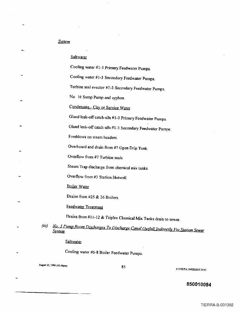
Saltwater
Cooling water #1-3 Primary Feedwater Pumps.
Cooling water #1-3 Secondary Feedwater Pumps.
Turbine seal evactor #1-3 Secondary Feedwater Pumps.
No. 16 Sump Pump and syphon.
Condensate - City or Service Wat&!:
Gland leak-off catch-ails #1-3 Primary Feedwater Pumps.
Gland leak-off catch-ails #1-3 Secondary Feedwater Pumps:
Freeblows On steam headers.
Overboard and drain from #7 Open Drip Tank.
Overflow from #7 Turbine seals.
Steam Trap discharge from chemical mix tanks.
Overflow from #3 Station HotwelJ.
Boiler Water
Drains from #25 & 26 Boilers.
Feedwater Treatment
Drains from #1 1-12 & Triplex Chemical Mix Tanks drain to sewer.
(iii) No. 3 Pum~
Saltwater
Cooling water #6-8 Boiler Feedwater Pumps.
AIlgU8I13, 1996 (lO:3~pm) 85S:IUSEP A.I 04\ESSEX.DOC
850010084
TIERRA-B-001382

Steam syphon from trench.
Discharge from steam header manifolds.
Condensat~
Gland leak-off catch-ails #6-9 Boiler Feedwater Pumps.
Drains from #6-9 Boiler Feedwater Pumps.
Overflow and drains #5-6-7 Open Heaters.
Overflow #3 Surge Tarue
Freeblows and traps from steam headers.
(iv) Fuel Qj! Room Discharge To Discharge Canal Qut[alllndirectly Via Station SewerSystem
Saltwater
Cooling water # 1-3 Fuel Oil Pump Reduction Gears.
Condensat~
L.P. Steam Traps on #1-3 Fuel Oil Pump Turbines.
(v)
Sump pump discharges condensate from steam traps and seepage.5
(vi) creenHouse
Saltwate[
Wash water for Canal Screens.
Condensate
SThis line was rerouted directly to the Passaic River in 1959.
Augwt 13, 1996 (lO:38pm) 86S:\USEP A.104IESSEX.DOC
850010085
TIERRA-B-001383

Heating system traps.
(vii) No.1 Unit - Elev. 100'
Saltwater
Cooling water #11-12-13 Mills.
Drain and overflow #11-12 Acid Cleaning Tanks.
Overflow from seal # 11~12 Ash Tanks.
Condensate
Catch-all drains # 11-12-13 Boiler Feedwater Pumps.
Drain from #11 Drain Tank.
Drain from Condensate System.
Boiler Water
Drains from # I Boiler.
4.1.1.2 Ash Pit Overflow Outfall
Circa 1948, the ash sluice trench was modified and the ash pit was removed from service.
The modified ash sluice trench was tied directly to the ash pit overflow outfall. Wastewater
effluents routed to this modified outfall included the foJlowing:
Surface runoff
Laundry effluent
Boiler Nos. 25 and 26 sluiceway effluents included boiler seal water overflow andmiscellaneous leakage from piping and valves
Auguo113. 1996 (lO:38pm) 87 S:\USEP A.104IESSEX.lJOC
850010086
TIERRA-B-001384

Surface water runoff and spillage from the chemical unloading area
Miscellaneous roof and floor drains
4.1.1.3 Cable Vault Sump Pump Outfall
Groundwater and surface water runoff in an electrical cable vault located in the northwest
section of property.
4.1.1.4 Ash Lake Overflow Outfall
Overflow in ash lake from ash sluice from No. I, No. 25 and No. 26 boilers
Overflow in ash lake from Air Heater Wash Water from No. I, No. 25 and No. 26boilers
4.1.1.5 Drainage Ditch
Certain wastewater effluents were routed to a naturally occurring on-site drainage ditch
which flowed to the Passaic River. Wastewater effluents routed to the drainage ditch included
groundwater and surface water collections in the Station's other electrical cable vault.
Circa 1963, the following effluents were routed to the drainage ditch:
Boiler blowdown pit overflow
Augwl 13, 1996 (lO:38pm) 88 S :\USEP A.I O4IESSEX.DOC
850010087
TIERRA-B-001385

No.8 combustion gas turbine building and equipment drain and non-contact cooling water
Surface water ru;lOff
4.1.2 Circa 1970 Modifications to Effluent Discharge System
Circa 1970, the Station modified certain of the processes associated with the management
of cooling and wastewater effluents. The principal modification involved the installation of a
288,000 gallon chemical waste basin. The basin was an above ground structure with a liner and
a dike. Approximate dimensions of the basin were 50 ft wide, 100 ft long, and 8 ft deep. The
basin discharge was routed to the former ash pit overflow outfall (hereinafter referred to as
Discharge Serial Number - "DSN" 342). Certain of the wastewater effluents were re-routed to
the basin for primary treatment prior to discharge to the Passaic River via DSN 342. These
wastewater effluents included wastewaters from low pressure boiler blowdown, high pressure
boiler air heater washes and high pressure boiler washes. This modi.fication coincided with the
termination of the Station's use of coal as a fuel, and the removal of the ash lakes and ash lake
overflow outfall from service. The final modification involved a change in practice with respect
to chemical cleanings. Spent cleaning solutions generated by the chemical cleaning of major
equipment were no longer discharged to the Passaic River, but disposed off-site.
4.1.3 NPDES Permitting
Subsequent to the enactment of the Federal Water Pollution Control Act of 1972 and
AU£UI1IJ, 1996 (JO:38pm) 89 S,\USEPA-I04IE.SSEX.DOC
850010088
TIERRA-B-001386

USEP A's assumption of primary responsibility for implementation of the NPDES pennitting
program, PSE&G submitted a revised application for an NPDES permit in November 1973.
This revised application reflected the cooling and wastewater management system described
above. The application was supplemented in May 1974, when PSE&G advised USEPA that the
low pressure and certain of the high pressure steam electric generating equipment had been
removed from service. These submissions identified discharges directly to the Passaic River
consisting of: river water for condenser and condensate cooling and miscellaneous heat
exchanger cooling; condensate and city water leakage from equipment; roof and floor drains; and
traveling screen wash water. These submissions also identified other discharges (i.e., fireside
washes, boiler blowdowns and air heater washes) to the chemical waste basin and then to the
Passaic River. In January 1975, USEPA issued PSE&G NPDES Permit No. NJ0000565 for
Station outfalls DSNs 341 and 342 with an effective date of January 30, 1975.
By letter dated August 15, 1978, PSE&G advised the USEPA that it had placed on
inactive status all steam electric generating equipment at the Station. PSE&G advised that it
would, however, have periodic batch discharges of approximately lO,OOOgallons per year of
boiler blowndown and drains associated with the continued operation of a low pressure boiler for
house heating. PSE&G further advised that these wastewater effiuents would be routed to the
chemical waste basin for primary treatment prior to discharge to the Passaic River. Operations
of the remaining low pressure boiler were terminated in 1979 with the installation of a package
boiler for house heating. The low pressure boiler remained inactive and was eventually
dismantled and removed from the site circa 1990.
Augwt 13, 1996 (1O:38pm) 90 S:\USEP AI04IESSEX.1XlC
850010089
TIERRA-B-001387

PSE&G submitted an application for renewal ofthe Station's NPDES permit in August
1979. The renewal application generally identified two outfalls to the River, DSNs 341 and 342,
and a sanitary sewer connection to PVSC. Effluent described as rainwater or groundwater
seepage from Station building sumps was identified as being routed to the discharge canal (DSN
341) or the overboard line adjacent to the discharge canal for discharge to the Passaic River.
Annual flow was estimated at 50,000 gallons per year. No pollutants were identified as being
present since all equipment had been deactivated, drained and/or flushed. With respect to DSN
342, the application indicated that approximately 25,000 gallons per year would enter the
chemical waste basin -- 10,000 gallons would have been effluent from boiler blowdown and
boiler drains and 15,000 gallons would have been rain water that would collect in the basin. The
application indicated that there would be no discharge via DSN 342 to the Passaic River since
the basin's outlet valve would remain closed and the influents would be allowed to evaporate in
the basin.
Circa 1980, Station operations consisted of electric power generation using combustion
turbines. Net generating capacity was 664,333 kW. Electric generation by use of combustion
turbine did not involve the discharge of cooling or wastewater effluents to surface waters. The
one low pressure boiler then in operation had been removed from service, as the steam used for
house heating was then being supplied by a package boiler. Blowdown from the package boiler
was initially routed to the chemical waste basin where it was evaporated. The blowdown was
subsequently routed to a flash tank in the Switch House basement where it was pumped to the
sewage ejector pit for discharge to the PVSC system. Circa 1980, effluent discharges from the
Augwt 13, 1996 (I0:38pm) 91 S:\USEPA1 04\ESSEX.DOC
850010090
TIERRA-B-001388

Station generally were limited to stormwater and groundwater seepage in buildings. These
effluents were being routed to existing outfalls for discharge to the Passaic River.
The NJDEP issued the Station a renewal permit in 1986 which authorized the Station to
discharge non-process waste waters, specifically untreated stonnwater, through three outfalls.
The permit provided that neither discharge of non-contact cooling water via the discharge canal
outfall nor discharge of process water via the former ash pit overflow outfall would be permitted
without prior approval from NJDEP since the steam units had been retired.
PSE&G submitted a permit renewal application for the Station in 1990. Supplements to
this application were filed. Circa 1990, field work activities associated with the demolition of the
Station commenced. Demolition of the Station was completed in 1992. Equipment remaining at
the Station includes combustion turbines, above ground fuel oil storage structures and electrical
switching equipment located in the Switch House. The NJDEP issued a renewal NJPDES permit
for the Station effective July 1995 permitting the discharge of stormwater from existing process
areas associated with the combustion turbines and oil storage structures.
4.1.4 Discharges to Passaic Valley Sewerage Commission
In 1927, the Station's sanitary sewer system was connected to the PVSC System. Circa
1970, wastewaters from the Station's laundry were also routed to the PVSC.
Augwl 13, 1996 (1O;38pm) 92 S:\USEP AI04IESSEX.DOC
850010091
TIERRA-B-001389

In ]975, the PVSC advised PSE&G that all industries were required to remove
incompatible pollutants' prior to discharge to the PVSC system and requested certain information
regarding Essex's discharges to the PVSC and to the Passaic River. PSE&G's response
indicated that the only discharge to the PVSC from the Station was sanitary wastes. PSE&G
supplied analytical results for sanitary waste waters collected at its Hudson Generating Station
since no data were available relative to the effluent discharged from Essex. PSE&G stated that
the Hudson data were deemed to be representative of the sanitary waste effluent from Essex.
PSE&G provided analytical data used in NPDES applications relative to the quality and quantity
of pollutants present in effluents discharged to the Passaic River via two outfalls: (1) the "Main
Discharge Canal" which consisted of river water treated with chlorine used for non-contact
cooling; and (2) the "Overboard Line" which consisted primarily of blow down from the low
pressure boiler used for house heating and, occasionally, wash waters from air heater and fireside
washes.
The quantity of effluent discharged to PVSC decreased as Station operations were
removed from service. In] 988, PVSC requested and PSE&G completed a Questionnaire for
Potential Large Industrial User. PVSC forwarded to PSE&G in 1989 an application for a
sewage connection permit. PSE&G completed the application, advising the PVSC that the
Station did not produce process wastes and there were no manufacturing process discharges to
the PVSC system. The Station's sanitary sewer system continues to discharge to the PVSC
system.
August n, 1996 (10:3Spm) 93 S,IUSEPA.l04IESSEX.DOC
850010092
TIERRA-B-001390

4.2 Air Permits and Emissions
New Jersey amended its air pollution control statute in 1967 to provide, in pertinent part,
that "no person shall construct, install, or alter any equipment or control apparatus" unless an
application had been filed and the NJDEP had issued a permit to construct andlor a certificate to
operate ("Air Permit") such equipment or apparatus. The statute also provided the NJDEP with
the requisite discretion to phase in the statutorily mandated air permit program. Commencing in
1968, the N.J. Department of Health ("NJDOH") and then the NJDEP adopted implementing
regulations under N.J.A.C. 7:27-8.1, ~~. specifying the types of equipment requiring an air
permit, if such equipment were installed, constructed or altered after the dates specified in the
regulations. In effect, the regulations exempted from the air permitting requirements equipment
which was constructed or installed (and not altered) after a given date ("Grandfathered
Equipment").
Section 2.a above describes the various types of equipment at Essex and provides the
installation dates for each. Although the types of equipment at Essex (e.g., boilers, fuel oil
tanks) were among the types of sources requiring air permits under N.J.A.C. 7:27-8.1 ~~, the
equipment was deemed Grandfathered Equipment in that it was constructed prior to the
designated date triggering an air permit.
Although much of the equipment at Essex was not subject to the requirements ofN.J.A.C.
7:27-8.1 ~ £e.Q... air permits have been obtained for the following Station equipment:
Augw113. 1996 00:31pm) 94 S~USEPA.I04IESSEX.DOC
850010093
TIERRA-B-001391

PSE&G installed an Auxiliary Boiler, commonly referred to as a "House Heating Boiler"
in 1979. The boiler had a maximum heat input of 4.0 MMBtu/hr. PSE&G applied for
and was issued an Air Permit for this boiler in 1979. The boiler was removed from
service in 1994, and its Air Pennit was canceled.
PSE&G installed an 8,000 gallon fuel oil tank in 1979 to serve the House Heating Boiler
referred to as the "No.2 Fuel Oil Tank at the Switch House". Although an Air Permit had
been issued for this tank, a subsequent review indicated that no pennit was actually
required for this tank because it had a capacity ofless than ]0,000 gallons and stored a
volatile organic liquid with a vapor pressure ofless than 0.02 pounds per square inch
absolute ("psi a") at standard conditions. This tank was removed from service in 1994 and
the Air Permit was canceled at or about that time.
Combustion turbine Unit NO.9 was replaced in 1990 with a new state-of-the-art
combustion turbine unit ("New Unit No.9"). The Station applied for an Air Permit in
1989 to operate New Unit NO.9 using natural gas. PSE&G conducted ambient air quality
studies in connection with the preparation of the application. Mathematical modeling,
which relied upon manufacturer's emission data and proposed unit operations, was used to
determine whether the proposed Unit 9 would cause or significantly contribute to an
exceedance of an ambient air quality standard. In conjunction with the Unit 9 modeling
studies, less rigorous modeling studies were conducted for Units 10, 11 and ]2, using
August 13, 1996 (I0:31pm) 95 S,IUSEPAI04IESSEX.OOC
850010094
TIERRA-B-001392

estimates of exhaust gas characteristics as model inputs. The modeling studies for Units
10-12 was performed to identify issues that might arise if the modeling study for Unit 9
would have predicted the potential to cause an exceedance of a significant impact level.
• NJDEP issued an Air Permit/Certificate in 1990 for New Unit No.9 which was amended
in 1993, based upon PSE&G's supplementary application, to allow New Unit NO.9 to
burn natural gas as the primary fuel and distillate oil as a secondary fuel. This Air Permit,
in part, requires stack testing every five years for NOx, Carbon monoxide ("CO"), non-
methane hydrocarbons, total suspended particulates (''TSP'') and PM-IO. In addition, it
required the installation and operation of a continuous emission monitor ("CEM") to
record NOx, CO and O2 emission data. Annual emission reports for the emission years
1990 and 1992 through 1995; and data from the CEMs for the years 1990 through 1995
are available upon request.
In early 1990, Congress enacted the Clean Air Act Amendments of 1990 ("CAAA").
New Jersey also adopted major amendments to its air pollution control statute in 1993. Each of
these acts and their implementing regulations established supplemental requirements and/or
standards relative to the control of air pollution, certain of which were applicable to the Station.
Title V of the CAAA requires states to develop and implement facility-wide operating
permit programs. The USEPA and NJDEP promulgated regulations establishing facility-wide
operating permit programs ("Operating Permit"). In anticipation that the NJDEP might require
Au..... 13, 19% (10:311pm) 96 S:\USEP A.I O4IESSEX.DOC
850010095
TIERRA-B-001393

applicants for Title V permits to submit ambient air quality analyses (for certain criteria
pollutants and TSP) with such applications, PSE&G conducted preliminary, in-house modeling
studies for Unit Nos. 10, 11 and 12 between 1992 and 1995. Sensitivity analyses were
conducted in 1994 and 1995 to address, among other things, uncertainties in model inputs, (e.g.,
emission rates, exhaust gas flow and temperature and exhaust gas velocity) the complexity of the
arrangement of structures surrounding the stacks, and changes in stack heights.
PSE&G, pursuant to the Operating Permit regulations, submitted an operating permit
application for all significant sources at Essex to the NJDEP in August 1995. The final
regulations adopted byNJDEP did not require the conduct of ambient air quality studies.
NJDEP advised PSE&G in January 1996 that its application was timely filed and administratively
complete. The application is currently undergoing technical review by the NJDEP.
In addition to the requirements to apply for an Operating Permit, the CAAA, the 1993
New Jersey Act and their' implementing regulations impose other requirements relative to the
control of air-borne emissions from Essex. In this regard, PSE&G has, among other things: (1)
made submittals to NJDEP relative to applicable NOx RACT requirements including a system-
wide NOli'Emissions Averaging Plan which was approved by NJDEP in November 1995~(2)
made submittals to NJDEP relative to applicable volatile organic compounds ("VOC") RACT
requirements; and (3) filed requisite data and reports with USEPA and NJDEP.
PSE&G also has conducted a limited number of stack tests at Essex. These include: (I) a
August 13, 1996 (I0:38pm) 97 S:\USEP A.I04IESSEX.DOC
850010096
TIERRA-B-001394

-series of stack tests on one stack at Unit 10 was performed to determine whether the TSP
emission rates were typ~cal ofPSE&G's fleet of combustion turbines and the extent of which
TSP is present in stack gases due: to the combustion process; background concentrations in the
ambient air; or particulates added to the ambient air that passes through the housing surrounding
the combustion turbine; and (2) a special study to investigate the reentrainment of exhaust gases
through the combustion turbines' air intakes.
Documents, correspondence, data, and written studies are available for inspection.
4.3 DPCCIDCRlSPCC Programs
Beginning in the mid 1970s with the promulgation by the USEPA of regulations pursuant
to Section 311 of the Clean Water Act, PSE&G was required to prepare a Spill Prevention
Control and Countermeasures ("SPCC") Plan for Essex. Pursuant to these USEPA regulations,
PSE&G developed and implemented an SPCC Plan for the Site which set forth specific
information with respect to the facilities, equipment and personnel at Essex relating to the
storage of oil at the Station as well as preventative measures and spill response plans for any spill
of oil into navigable waters.
Subsequently, the NJDEP developed a substantially similar regulatory program pursuant
to its authority under the New Jersey Spill Compensation and Control Act. This state regulatory
program, which is codified at NJ.A.C. 7: 1E-l ~., required PSE&G to prepare and to file
A\llUSI 13. 1996 (I0:38pm) 98 S:\USEP A.l04\ESSEX.OOC
850010097
TIERRA-B-001395

with the NJDEP a Discharge Prevention, Containment and Countermeasures ("DPCC") Plan and
a Discharge Cleanup and Removal ("DCR") Plan. The substance and purpose of the DPCC and
DCR Plans required by the NJDEP and the SPCC Plan required by USEPA were essentially
similar; however, the DPCC/DCR regulations expanded the scope of the program to include
discharges of hazardous substances.
Subsequent to the adoption of these regulations, PSE&G prepared a consolidated SPCC
and DPCCIDCR Plan. This consolidated Plan was submitted to the NJDEP in 1977.
Subsequent to this submission, the Station prepared revised Plans in response to a series of
NJDEP comments. The Plan received final NJDEP approval in 1986. A list of
SPCCIDPCCIDCR applicable storage and processing equipment (including underground storage
tanks ("USTs")) from circa 1980, through January 1996 are presented on Table 3.37. The list
does not include SPCCIDPCC applicable storage and processing equipment associated with the
steam electric generating facilities which had been removed from service as of 1978.
PSE&G has periodically updated, revised and supplemented its SPCCIDPCCIDCR Plan
for the Station in accordance with the requirements of applicable state and federal regulations.
These are on-going regulatory programs and PSE&G continued to have contact with NJDEP
and, from time to time, USEPA concerning issues relating to its SPCCIDPCCIDCR Plan for the
Station.
Pursuant to the Oil Pollution Act of 1990 ("OPA"), PSE&G was required to submit a
August 13, 1996 (I 0:38pm) 99 S:\USEPA.I04\ESSEX.DOC
850010098
TIERRA-B-001396

Facility Response Plan (t1FRP") for Essex in that the Station was, as of the applicable trigger
date, a non-transportation-related onshore facility. PSE&G submitted its FRP to USEPA on
February 18, 1993.
Upon completion of its initial review in June 1993, USEPA requested additional
information. This information was submitted in July 1993. In July 1994, USEPA advised
PSE&G that it had conducted another initial review and requested additional information. This
infonnation was submitted in September 1994. As of this date, PSE&G has not received notice
affinal agency action with respect to the FRP.
Available correspondence by and between PSE&G and relevant regulatory agencies
relating to SPCC/DPCC/DCRIOP A issues is available for inspection.
4.3.1 Spill Discharge History
The Station was an industrial operation that involved the handling and storage of materials
(primarily coal and oil). Spills and discharges that may have involved releases to the environment
occurred. Housekeeping policy and practice was directed at prevention, early detection and
expeditious corrective action. While PSE&G's file search is not yet complete, this section
presents a summary of discharge and spill incidents for which documentation has been located to
date, involving releases to the environment as detailed below:
Auguat 13, 1996 (!0:31pm) 100 S:IUSEPA.104IESSEX.DOC
850010099
TIERRA-B-001397

In June 1973, solidified No.6 Fuel Oil (Bunker C Fuel Oil) in a fuel oil heater became
heated, liquefied; and drained into a sump tank in the fuel oil room causing the tank to
overflow. The oil that overflowed the tank entered the Station's drain system and flowed
into the Passaic River. Spill response measures were performed by a contractor. There is
no documentation available estimating the quantity of material discharged. The discharge
was reported to the United States Coast Guard ("USCG") which responded. Corrective
actions were implemented with USCG oversight. There is no record that sampling of any
media was performed. The USCG issued a notice of violation ("NOV") which was
resolved.
In July 1973, NO.6 Fuel Oil leaked from a fuel oil heater valve causing oil to enter the
Station's drain system and flow into the Passaic River. Spill response measures were
performed by a contractor. There is no documentation available estimating the quantity of
material discharged. The discharge was reported to the USCG, the USCG responded, and
corrective actions were implemented with USCG oversight There is no record that
sampling of any media was performed. The USCG issued a NOV which was resolved.
In November 1974, No.6 Fuel Oil leaked from a valve on a fuel oil heater, entered the
Station's drain system and flowed into the Passaic River. Available information indicates
that approximately 40 gallons of fuel oil were discharged. Spill response measures were
perfonned by Station personnel. The discharge was reported to the USCG. The USCG
responded, and corrective actions were implemented with USCG oversight. There is no
Augual13, 1996 00:31pm) 101 S:\USEPAI04IESSEX.DOC
850010100
TIERRA-B-001398

....record that sampling of any media was perfonned. The USCG issued a NOV which was
resolved .
In October 1975, a thin narrow film of material was observed along the dock front. As
the tide receded, it appeared that the material was entering the river from DSN 342. The
material was described as a pale, bluish-gray substance; however, there was not enough
material present to collect a full sample. The material lacked the characteristic rainbow
spectrum sheen that an oil droplet displays over water. Further investigations suggested
that the material was a detergent, cleaning agent or non-petroleum type substance which
had entered the flow drain system of the low pressure boiler area. The USCG, NJDEP,
USEP A, and the PVSC were notified by Station personnel. The estimated quantity of
material was one to two quarts. Station personnel cleaned up the substance. One sample
was collected; however, due to the limited sample volume, all that could be concluded was
that the material was not oil. Available Station records do not indicate any further
regulatory actions as a result of the incident.
In January 1976, during a routine inspection by representatives of the PVSC, a black oily
liquid was observed being pumped from a manhole near the Station onto the ground
where it then flowed to Lawyers Ditch, a tributary of the Passaic River. The quantity and
constituent substances of this discharge are unknown. PSE&G employees complied with
the PVSC request to cease the pumping operation immediately. It is unknown whether
any remedial actions were taken with respect to this discharge.
A_In, 1996(lO;3Spm) 102 S;\USEP A.I04IESSEX.DOC
850010101
TIERRA-B-001399

In October 1989~ PSE&G notified the NJDEP hotline of a small leak detected at Fuel Oil
Tank No.1 during a tank cleaning associated with the planned retirement of the tank.
Several gallons of No. 6 Fuel Oil appeared outside the tank in the six inch area between
the tank and its concrete containment. The oil most likely appeared because the steam and
high pressure water was used to remove solidified NO.6 Fuel Oil from the tank. The oil
was then forced out of some of the small corrosion openings that had developed around
rivets which were part of the tank's construction. PSE&G cut holes in the tank floor to
inspect the ground under the tank. This inspection verified that oil leakage was limited
and that there was no potential hazard to the ground water or surface water.
When Fuel Oil Tank No. 1 was demolished in September 1990, PSE&G re-examined the
ground under the tank and found oil-soaked soil in the containment at the circumference
of the tank, which was collected in plastic bags and placed in the Station's hazardous
waste dumpster. There was some oil-soaked soil in the area of the tank sump. This area
did not have a heavy concentration of oil; however, PSE&G removed several cubic yards
of material, excavating as much as two feet below grade. There are no other records
related to this spill.
In June 1990, a kerosene leak:from an above ground storage tank was detected. The
kerosene that leaked from the tank was contained in the tank's secondary containment
system, an earthen dike with a c1aymax liner. Approximately 3,000 gallons of kerosene
August 13, 19% (lO:38pm) 103 S:\USEPA.104IESSEX.DOC
850010102
TIERRA-B-001400

entered into the secondary containment system. Response measures were initiated by
Station personnel and completed by a contractor. None of the material was discharged to
the ground and/or to the waters of the State. The leak was reported and actions to curtail
the leak and upgrade the tank to prevent future leaks were implemented with NJDEP
oversight. Sampling of environmental media was not performed.
In July 1990, a discharge of No. 4 Fuel Oil occurred at a relief plug in a pipeline pig-
catcher being used in an Amerada Hess fuel oil transfer pipeline located at the Station. As
a routine practice, Amerada Hess used NO.4 Fuel Oil to flush its transfer pipeline
following delivery of No. 6 Fuel Oil to the Station. Discharge response measures were
initiated by Amerada Hess personnel and completed by an Amerada Hess contractor.
Approximately 800 gallons of No. 4 fuel oil were discharged to the ground. None of the
material migrated to the Passaic River. The discharge was reported to NJDEP and
corrective actions were implemented. Sampling of environmental media was not
performed.
In Janual)' 1991, a leak of kerosene occurred in a below ground fuel oil delivery line for a
kerosene storage tank. Approximately 13,000 gallons of kerosene were discharged into
the ground. Seepage from the discharge migrated to the Passaic River. Discharge
response measures were initiated by Station personnel and completed by a contractor.
The discharge was reported to NJDEP, USCG and USEPA and corrective actions were
implemented with NJDEP and USCG oversight. The USCG issued a NOV which was
Augwt 13, 1996 (IO:38pm) 104 S:\USEPA.1 04\ESSEX.DOC
850010103
TIERRA-B-001401
resolved. The NJDEP also issued a NOV requiring PSE&G to implement a remedial
action program. PSE&G resolved the NOV by entering into a Memorandum of
Agreement ("MOA") pursuant to which a site remediation program was implemented.
The site remedial program included limited media characterization, excavation and off site
disposal of contaminated soils and a groundwater recovery and monitoring program; the
treated groundwater was discharged to the Passaic River. PSE&G completed the site
remedial program and the NJDEP issued PSE&G a No Further Action ("NFA") Letter in
June 1994.
In May 1992, a discharge occurred in an aboveground portion of a 26 kV cable dielectric
oil pipeline. Approximately 40 gallons of dielectric transil oil were discharged to the
ground surface. The discharged material did not migrate to the Passaic River. Response
measures were initiated by Station personnel. The discharge was reported to NJDEP and
corrective actions were implemented. Sampling of environmental media was not
performed. No violation was issued.
In May 1992, a leak occurred in a drum containing transil oil causing a discharge of
approximately one gallon oftransil oil to the ground. The discharged material did not
migrate to the Passaic River. Discharge response measures were performed by Station
personnel. The discharge was reported to NJDEP and corrective actions were
implemented. Sampling of environmental media was not performed.
AugwC 13, 1996 (IO:3~pm) 105 S:\USEPAI04IESSEX.DOC
850010104
TIERRA-B-001402

• In July 1992, petroleum hydrocarbon·contaminated soil was encountered in an excavation.
The source of the contamination was not identified. The discharge was reported to
NJDEP and corrective actions were implemented. Corrective actions involved the
excavation of soils in a discrete area visibly contaminated with petroleum hydrocarbons.
Sampling of environmental media was not performed.
In November 1992, a leak occurred in a fuel oil line for a combustion turbine unit.
Approximately 50 gallons of kerosene were discharged into the ground. The kerosene did
not migrate to the Passaic River. Discharge response measures were initiated by Station
personnel and completed by a contractor. The discharge was reported to the NJDEP and
corrective actions were implemented. Sampling of environmental media was not
performed.
In November 1992, a vent valve from an overhead section of a fuel oil line to a
combustion turbine unit opened causing a discharge of approximately 3,000 gallons of
kerosene to the ground. The kerosene did not migrate to the Passaic River. Discharge
response measures were initiated by Station personnel and completed by a contractor.
The discharge was reported and corrective actions implemented with NJDEP oversight.
Sampling of environmental media was performed. PSE&G implemented a site remedial
program under an MOA with the NJDEP. The program included post-excavation soil
sampling. A Remedial Action Report is currently being prepared.
Augusll3, 1996 (I0:38pm) 106 S:IUSEP A.I04IESSEX.DOC
850010105
TIERRA-B-001403

In January 1993, a leak occurred in an above ground purge fuel oil line for one ofthe
combustion turbine units. Approximately 15 gallons of kerosene were discharged to the
ground surface. The kerosene did not migrate to the Passaic River. The discharge was
reported to the NJDEP and corrective actions were implemented. Sampling of
environmental media was not performed.
• In September 1993, a transformer cooling radiator failed causing a discharge of
approximately 900 gallons of mineral oil to the ground surface. The extent of the
discharge was limited by the presence of a firewall under the transformer. The mineral oil
did not discharge to the Passaic River. Discharge response measures were initiated by
Station personnel and completed by a contractor. The discharge was reported and
corrective actions implemented with NJDEP oversight. Sampling of environmental media
was performed. PSE&G implemented a site remedial action program under an MOA with
the NJDEP. The program included the excavation and off-site disposal of contaminated
soils. A Remedial Action Report for this remedial program was submitted to the NJDEP.
NJDEP issued a NFA letter in June 1996.
In October 1993, approximately 30 gallons oftransil oil were discharged to the ground
during the course of an underground electrical transmission line repair project. The transil
oil did not migrate to the Passaic River. Discharge response measures were perfonned by
Station personnel. The discharge was reported to the NJDEP and corrective actions were
implemented. Sampling of environmental media was not performed.
AlIgWIll3, 1996 (IO:JHpm) 107 S:\USEP A 1G4\ESSEX.DOC
850010106
TIERRA-B-001404

In January 1994, a leak occurred in an above ground fuel pipeline causing the discharge of
approximately 5 gallons of kerosene to the ground surface. The kerosene did not migrate
to the Passaic River. Discharge response measures were performed by Station personnel.
The discharge was reported to the NJDEP and corrective actions were implemented.
Sampling of environmental media was not performed.
In March 1994, a leak occurred in an above ground fuel pipeline causing the discharge of
approximately 5 gallons of kerosene to the ground surface. The kerosene discharged did
not migrate to the Passaic River. Discharge response measures were performed by Station
personnel. The discharge was reported to the NJDEP and corrective actions were
implemented. Sampling of environmental media was not performed.
In June 1994, a discharge of purge oil from an above ground fuel oil line occurred due to
the failure of a fuel pump. Approximately four gallons of kerosene were discharged to
the ground surface. The kerosene did not migrate to the Passaic River. Discharge
response measures were performed by Station personnel. The discharge was reported to
the NJDEP and corrective actions were implemented. Sampling of environmental media
was not performed.
• In August 1994, a discharge of coolant from a gauge glass on a combustion turbine unit
cooling tower occurred as a result of an equipment malfunction. Approximately two
gallons of oil were discharged to the ground. The coolant did not migrate to the Passaic
August 13, 1996 (lO:38pm) 108 S:\USEPA.ID4\ESSEX.DOC
850010107
TIERRA-B-001405

River. Discharge response measures were performed by Station personnel. The discharge
was reported to the NIDEP and corrective actions were implemented. Sampling of
environmental media was not performed.
In September] 994, a kerosene residue was observed on the ground surface. The source
of the residue was not identified. The quantity of residue was estimated at approximately
two gallons. The residue did not migrate to the Passaic River. Discharge response
measures were performed by Station personnel. The discharge was reported to the
NIDEP and corrective actions were implemented. Sampling of environmental media was
not performed.
In October 1994, a 230 kV above ground oUstatic cable piping failed causing a discharge
of mineral oil to the ground surface. Approximately 15 gallons of mineral oil were
discharged. The mineral oil did not migrate to the Passaic River. Discharge response
measures were performed by Station personnel. The discharge was reported to the
NJDEP and corrective actions were implemented. Sampling of environmental media was
not performed.
• In May 1995, during the demolition of the old Unit No.9 combustion turbine, subsurface
deposits of lubricating oil and kerosene were encountered. Approximately 2,900 gallons
oflubricating oil and water were encountered. No estimate of the quantity of kerosene
encountered is available. The discharged materials did not migrate to the Passaic River.
Augwl 13, 1996 (10:31"",) 109S:IUSEP A.I04IESSEX.DOC
850010108
TIERRA-B-001406

-Discharge response measures were performed by Station personnel. The discharge was
reported to the NIDEP. No NOV was issued. Sampling of environmental media was
performed. PSE&G implemented a site remedial action program under a MOA with the
NJDEP. The program included the removal of the free product and excavation and off
site disposal of contaminated soils. PSE&G submitted a Remedial Action Report to
NJDEP in July 1996,
Available correspondence by and between PSE&G and relevant regulatory agencies
concerning these spill incidents is available for inspection. Available reports concerning sampling
of environmental media and any reports of corrections are also available for inspection.
4.4 Hazardous Waste Management
The Resource Conservation and Recovery Act ("RCRA") provides the basic framework
for regulation of hazardous waste. ReRA was adopted in 1976 as a revision and expansion of
the Solid Waste Disposal Act of 1965. It introduced a nationwide program for management of
hazardous wastes by controlling the generation, transportation, treatment, storage and/or
disposal of hazardous waste through a comprehensive system of hazardous waste management
requirements. The RCRA statute, .inter Alia, directed USEPA to develop standards for handling,
tracking and disposing of hazardous wastes. USEP A adopted certain implementing regulations
in 1980.
AUgust 13, 1996 (IO:31lpm) 110 S:\USEPA.I04IESSEX.DOC
850010109
TIERRA-B-001407

RCRA regulations create an elaborate system for tracking hazardous waste from the time
it is generated until its ultimate disposal. RCRA divides the universe of entities that shepherd
hazardous waste through its life cycle into categories. Generators are one such category and
include "[a]ny person, by site, whose act or process produces hazardous waste." Generators
bear responsibility for determining whether their solid waste is hazardous. Upon making such a
determination, they must: (l) obtain a hazardous waste identification number from USEPA; (2)
carefully package and label wastes; (3) ship them to an authorized treatment, storage and
disposal facility; and, (4) prepare a manifest which tracks the waste from the generator's site to
its ultimate disposal site. Generators must bieIUlially submit'reports on waste generating
activities,
iRCRA provides that States may establish their own hazardous waste programs so long as
they meet or exceed minimum USEPA requirements. Over period from 1978 through 1981,
New Jersey adopted regulations implementing a hazardous waste program consistent with
federal requirements, (See N.J.A.C. 7:26-1 et seq.). Pursuant to the New Jersey Solid Waste
Management Act (NJ.S.A. 13:1E-l ~ gq.) These regulations imposed requirements on
generators associated with, inter 1ill.a, the management for off-site disposal of hazardous wastes.
These regulations require, inter alia, that generators: (1) have an USEPA generator J.D. No.; (2)
complete a USEP NNJDEP-approved hazardous waste manifest form in connection with the off-
site disposal of hazardous wastes; (3) file with the NJDEP an annual report of such shipments;
and, (4) retain manifests and annual reports for a period of three years.
August 13, 1996 (lO:38pm) 111 S:IUSEPA.I04IESSEX.DOC
850010110
TIERRA-B-001408

In 1980, the Station obtained a USEPA generator number (No. NJD000574000). The
Station submitted Hazardous Waste Generator Annual Reports to the NJDEP thereafter.
The Station's Hazardous Waste Manifests for the years 1989 through 1995 and
Hazardous Waste Generator Annual Reports for the years 1984 through 1995 are available for
inspection.
4.5 Underground Storage Tanks
New Jersey enacted a statute in )986 (as amended in 1990) providing for, inter alia, the
registration of underground storage tanks ("USTslI). Station USTs were identified in connection
with the preparation of the SPCCIDPCCIDCR Plan (see Table 3.37). The Station initiated the
registration process for certain of the USTs then at the Station. At that time, there were twenty-
five USTs at the Station.6 These USTs are identified in Table 3.39.
The twenty-five USTs fall into three categories: twenty-one purge oil collection USTs for
the combustion turbine generations; three USTs used for vehicle fuel storage; and one UST used
for lube oil storage.
With respect to the three vehicle fuel storage USTs, records indicate the following: two
6As discussed in Section 3.6.5 above, a 1,000 gallon steel UST for diesel fuel oil storagehad been installed circa 1924. Records are not available with respect to the removal of this tarue
Augwt 13, 1996 (I0:38pm) Il2 8:\U8EP A.104IESSEX.DOC
850010111
TIERRA-B-001409

were of steel construction and one was fiberglass; the 3,000 gallon diesel UST was installed in
1951; and there is no indication of an installation date for the other two USTs. Records relating
to the regulatory registration and compliance with then-applicable NJDEP regulatory
requirements with respect to these three USTs are incomplete. There is an indication that the
3,000 gallon diesel UST was registered pursuant to NJDEP regulations. In April 1988, all three
of these vehicle fuel USTs were removed, according to available records.
The lube oil UST was discovered in 1989 under the coal tower. It was cleaned and
removed by a contractor in September 1989. There are no records indicating whether it was
registered, nor is there any indication of its size or condition.
The twenty-one purge oil USTs were installed for the combustion turbines. These USTs
were not initially registered with the NJDEP because, as flow through process tanks, they were
exempt from regulation under then-applicable NJDEP rules. Records indicate that circa 1990,
five of these USTs were removed. The remaining sixteen USTs were registered with the NJDEP
after a regulatory amendment required such registration. In 1992, PSE&G instituted closure and
removal of these sixteen USTs pursuant to applicable NJDEP regulations and with NJDEP
oversight. Site assessment work related to these UST removals is on-going.
Relevant records relating to Station USTs are available for inspection.
4.6 Floods, Fires and Other Incidents
A_! 13. 1996 (lO:38pm) 113 S:\USEP A.104IESSEX.DOC
850010112
TIERRA-B-001410

...Based on available inforamtion, several floods, fires and explosions occurred at Essex over
the operating life of the Station. These incidents are summarized below .
Explosion and Fire -- A & B Group Selector Oil Switches and Equipment...
An explosion and fire occurred on the "A & B Group Selector Oil Switches and
Equipment" on May 16, 1927. Damage was extensive, necessitating the replacement of nine
barrier walls in the oil circuit breaker compartments and forty-two cell doors. Repairs were
made to the A & B Group selector oil switches, disconnecting switches, current transfonners,
control wiring, cable compartments, and compartment doors in the 4th and 5th floors of the
Switch House.
Fire on Fifth Floor Switch House
A fire occurred in the Switch House at Essex on December 28, 1936. Relevant file
information describing the maintenance work that was performed to repair the damage to the
Switch House is available. Section 3.8 above provides additional information relative to these
repairs.
Fire on Sixth Floor Switch House
On August 19, 1938 at 6:38 p.m., a bus short circuited, igniting a fire between Nos. 2 and
Augwt 13, 1'196 (10:38pm) 114 S:\USEPA.I04\ESSEX.rx:x:
850010113
TIERRA-B-001411

3 phases on the new M-group tie bus on the sixth floor of the Switch House. This fire damaged
the 13,000 volt bus, bus insulators, disconnecting switches, and compartment structures and
doors. Repairs were completed on or before September 21, 1938.
Dock Collapse
On September 14, 1948, the dock collapsed between the coal tower and discharge canal.
Although the dock had been recapped in 1937, the support piles had been installed in 1915. As a
safety precaution, the small section of the dock which remained after the collapse was removed.
Both sections of the dock were completely rebuilt
Storm Damage
Various ancillary equipment and building structures (e.g., cracked lights and windows, building
roofs, screen doors), were damaged during a severe wind storm which took place on November
25, 1950.
Many areas of the Essex property were flooded during the "NorEaster" (Northeastern)
storm of March 6, 1962. During this stann, available records indicated that river elevation in the
vicinity of the Harrison Gas Plant upriver of Essex reached 7.78 ft. above mean sea level. Cars
AIIgIlBI 13, 19% (I0:3~pm) 115 S:IUSEP A. i04IESSEX.DOC
850010114
TIERRA-B-001412

parked on Station property were caught in waters which reached the elevation ofa standard car's
steering wheel.
No.6 Unit Condenser Explosion
An explosion occurred in the Unit No.6 condenser circa 1971. No records, other than
photographs, have been located relative to this event.
Unit No. 10 Fire. 103 Inlet Filters
A fire occurred on No. 10 Unit, 103 Inlet Filters on June 27, 1994 at 2:39 p.m. The local
fire department responded and extinguished the burning filters. No release of materials was
reported.
No.9 Gas Turbine Fire
The old Unit No.9 combustion turbine was destroyed by fire on January 3, 1989. The fire
began at approximately 8:00 p.m. when lube oil ignited. Foam and chemical fire protection
systems were activated. Station personnel used a 150 lb cylinder of "K" dry chemical on the fire.
The Newark Fire Department was called and the fire was extinguished by approximately 8:45
p.m. The unit was damaged beyond repair and was eventually demolished in 1995. A New Unit
No.9 was constructed in the early 1990s to replace the damaged unit.
J\ugual n. 1996 00:31pm) 116 S:IUSEPA 104\ESSEX.DOC
850010115
TIERRA-B-001413

In December 1992, a storm caused excessively high tides. Flood waters inundated the
Station. Available information indicates that these flood waters did not rise over the level of any
secondary containments. There is no record of a release of a hazardous substance as a result of
this flood.
4.7 Environmental Media Studies/Analyses
Analytical data from environmental media sampling at Essex may be summarized as
follows:
In November 1989, approximately 6,000 cu. yd. of soil was excavated in connection with
the preparations for New Unit NO.9 foundation construction. Analysis was performed to
conduct a waste classification pursuant to NJDEP solid waste regulations. Excavated
soils were classified as ill27 non-hazardous waste and recycled as asphalt aggregate.
• As a result of a kerosene delivery pipe failure discovered on January 28, 1991,
approximately 13,000 gallons of kerosene was discharged into the ground. During
remediation of the discharge, periodic groundwater monitoring was conducted. Final
groundwater sampling results submitted to NJDEP in 1992 reported levels below
published standards for groundwater classification Class IIA cleanup standards. NJDEP
AugusI13, 1996 (IO:3BpmJ 117 S:IUSEP A.I04IESSEX.OOC
850010116
TIERRA-B-001414

has issued a NF A letter.
• During demolition of the Steam Station in 1991, PCBs were found to be present in several
pieces of electrical switching equipment for No. 1 Unit. The foundation and surrounding
soil were sampled. The sampling from the concrete foundation had elevated levels of
PCBs which were remediated. Post-remediation sampling indicated that the remaining
concrete and surrounding soil levels were below NJDEP cleanup guidance levels for
residential areas.
Post-excavation soil samples taken in an area impacted by a discharge of3,000 gallons of
kerosene in November 24, 1992 indicated non-detects for VOCs. A Remedial Action
Report is currently being prepared.
Following the remediation of the area under a 132-1 transformer phase which had a
radiator fail in 1993, post excavation samples were taken. A Remedial Action Report was
submitted to NJDEP in May 1996.
During demolition of old No.9 Unit in April 1995, approximately 2,900 gallons of oil and
water were found under the foundation. Kerosene was also detected during post-
excavation sampling and additional soils were excavated. The combustion turbine,
including the foundation, was demolished and the soil surrounding the unit was excavated.
Post-excavation soil and groundwater indicated that residual levels were below NJDEP
Auguol13, 19% (10:311pm) 118 S:\USEPA.I04\ESSEX.DOC
850010117
TIERRA-B-001415

residential cleanup guidance levels. A Remedial Action Report was submitted to the
NJDEP in July 1996.
Groundwater monitoring wells and post-excavation soil and groundwater samples were
collected and analyzed under the NJDEP-approved closure plan associated with the closure of
sixteen purge oil collection tanks. Activities relative to the closure plan are continuing under
NJDEP guidance.
August 13, 1996 (IO:3!lpm) 119 S:IUSEPA. J 04IESSEX.DOC
850010118
TIERRA-B-001416

Table 3.1
Table 3.2
Table 3.3
Table 3.4
Table 3.5
Table 3.6
Table 3.7
Table 3.8
Table 3.9
Table 3.10
Table 3.1 J
Table3.12
Table 3.13
Table 3.14
Table 3.15
Table 3.16
Table 3.17
Table 3.18
Table 3.19
Table 3.20
Table 3.21
ESSEX GENERATING STATIONLIST OF TABLES
Low Pressure Units - Operating Parameters
Raw Materials - Low Pressure Boilers (191 5-1978)
Typical Low Pressure Boiler Chemistry Limits (1915-1978)
Boiler Blowdown - Low Pressure Boilers (1915-1978)
Fuels/Generation Statistics - Essex Generating Station
Pennsylvania and West Virginia Bituminous Coal ConstituentslProperties
Bituminous Coals from West Virginia - Hazardous Substances
Bitumlnous Coals from Pennsylvania - Hazardous Substances
Bituminous Coal from Eastern USGS Province - Hazardous Substances
No.6 Fuel Oil - Typical Properties
No.6 Fuel Oil - Hazardous Substances
Bituminous Bollom Ash from West Virginia Coal - Hazardous Substances
Bituminous Fly Ash from West Virginia Coal - Hazardous Substances
Bituminous Bottom Ash from Pennsylvania Coal - Hazardous Substances
Bituminous Collected Fly Ash from Pennsylvania Coal - Hazardous Substances
Bottom Ash Sluice Water, Western Pennsylvania Bituminous Coals _ HazardousSubstances, Metals
Ash Pond Effluent from Western Pennsylvania Coat - Hazardous Substances
Available Information - Condenser Chemical Cleanings (Unit Nos. I through 6)
High Pressure Units - Operating Parameters
Raw Materials - Unit No.7, Boilers 25 & 26 (1937-1974)
Typical Boiler Units 25 & 26, High Pressure Boiler Chemistry Limits
850010119
TIERRA-B-001417

....
Table 3.22
Table 3.23
Table 3.24
Table 3.25
Table 3.26
Table 3.27
Table 3.28
.... Table 3.29
Table 3.30
Table 3.31
Table 3.32
Table 3.33
Table 3.34
Table 3.35
Table 3.36
Table 3.37
Table 3.38
Table 3.39
Table 3.40
Table 3.41
Table 3.42
ESSEX GENERATING STATIONLIST OF TABLES
Available Information - Boiler Chemical Cleanings (Boiler Nos. 25 & 26)
Summary of Feedwater Heater Chemical Cleanings (Boiler Nos. 25 & 26)
Typical HCI Boiler Chemical Cleaning Drain Water Characteristics
Raw Materials - Unit No.1 (1947-1978)
Natural Gas - Typical Chemical Composition
Typical Unit No. 1 High Pressure Boiler Chemistry Limits
Summary of Boiler Chemical Clcanings (New Unit No I)
Summary of Condenser Chemical Cleanings (New Unit No. ))
Summary of Feedwater Heater Chemical Cleanings (New Unit No. ))
Combustion Turbine Units - Operating Parameters
Low Sulfur Distillate Fuel Oil - Typical Characteristics
Kerosene - Typical Characteristics
Low Sulfur Distillate Fuel Oil - Metallic Hazardous Substances
Kerosene - Hazardous Substances
Raw Materials - Combustion Turbines
Essex Generating Station Storage and Process Equipment
Lubricating Oils - Hazardous Substances
Essex Generating Station - Underground Storage Tanks
Summary of ACOE Dredging Along Passaic River
Characteristics ofTransil Oils Supplied by Various Equipment Manufacturers
Switching <lnd Gener<lting Station Stor<lge Tanks - Oil Analysis
850010120
TIERRA-B-001418

Figure 2.1
Figure 2.2
Figure 2.3
Figure 2.4
Figure 2.5
Figure 2.6
Figure 2.7
Figure 3.1
Figure 3.2
Figure 3.3
figure 3,4
ESSEX GENERATING STA TIONLIST OF FIGURES
Site Map - Essex Generating and Switching Station (U.S.C.&G.S., Jersey CityQuadrangle)
Site Ownership Transactions Map
Station Site Plan Circa 1925
Station Site Plan Circa 1940
Station Site Plan Circa 1951
Station Site Plan Circa 1974
Station Site Plan Circa 1996
Process Flow Diagram - Low Pressure Tu rbine/Generators and Boilers (1915-1978)
Process Flow Diagram - Addition of No. 7 High Pressure Turbine/Generator andNos. 25 & 26 Boilers (1937-]974)
Process Flow Diagram - Addition of New Unit No. I and Ash Lake (1947-1978)
Process Flow Diagram - Simple Cycle Combustion Turbines (1963-Present)
850010121
TIERRA-B-001419

CERTIFICATION OF ANSWERS TO REOUEST FOR INFORMATION
State of New Jerseyss.
County of Essex
I certify under penalty of law that I have personally examinedand am familiar with the information submitted in this document(response to EPA Request for Information) and all documentssubmitted herewith, and that based on my inquiry of thoseindividuals immediately responsible for obtaining theinformation, I believe that the submitted information is true,accurate, and complete, and that all documents submitted herewithare complete and authentic unless otherwise indicated. I amaware that there are significant penalties for submitting falseinformation, including the possibility of fine and imprisonment.I am also aware that my company is under a continuing obligationto supplement its response to EPA's Request for Information ifany additional information relevant to the matters addressed inEPA's Request for Information or the company's response theretoshould become known or available to the company.
Horace G. CampbellNAME (print or type)
Manager, Site Remediation, Project Development - FossilTlb (pnnt :;p~~~~r-Sworn to before me this 13th dayof August, 1996.
~"])d}+-~Notary Public
Rosann DelTufo.UiIorioNOTARY PU8UC OJ HEW JERSEy
\4y Comiftissjon Expires May 14, 1999
850010122
TIERRA-B-001420

...... --------'"-------~ ......~-_...~~.~,.. -~-_.~.-,---. -~....._-- -'.'~-~ ..... _ .. ~.-
850010123
TIERRA-B-001421

Table 3.1
Low Pressure Units - Operating Parameters
Low Pressure Boilers
Year Installed No, of BoilN'S Fuels'Manufactul'er HP PIUSUI'e(psi)
[j915
11373B&W 4 Coal, Oil242
I 1917 B&W 242 8 Coal, Oil1278
1919 B&W 1278 4 Coal, Oil242
InJ B&W 2 ConI, Oil1859 2411924 B&W 1859 242 6 Coal, Oil
Low Pressure Steam Turbine/GeneratorsF-~~~~~"F""M~lI~nu~f";a~ct~u~I'~er-'l,~-;, r-~ ,'r---V-o-IIs-~---r-M-aX-in-l-u-m-G-en-e-I'-Bt-o-r--~
Nome Plate Racing (KW)YeRl'llIstalled
]1 ·1 ". SIlO 1 m'110 I 13.21lO "13J·500 I 25,0001 13,200 22500 KW
1915 GE 22500 KW
1915 (iE
[ " 191R GE 53.6ll0 4ll.1I00 13,200 411,OOllKW
'I 47)()(l -I 35.DnO ILI923 OE 36.(10(1 KW13,20{)
192) GE 3S,DOO 13,200 36,000 KW
1924 (IE 56.600 13,200 36,OOOKW40.(I01l
B&W = Babcock & WilcoxGE = General ElectricHP = Horsepowerpsi ~ Poul1ds Per Square Il1chKW = Kilowatts
IEssex began using No.6 Fuel Oil, Circa 19]].
850010124
TIERRA-B-001422

Table 3.2
Raw MaterialsLow Pressure Boilers
Essex Generating Station 1915 to 1978
Materials Use and Descrilltion EPA CERCLA U.t.dL,Il.r Sub"an ..,
I!
F..t"Dilumin<lu5 Coal (WVa &. PA Sources) Boiler Fuel ..No.6 Fuel Oil , Boiler Fuel .. .Combustion Air i Boil"'" and Combu£lion Turbines
1'"..1A,ldlll" ... fir T ... al .... DI.
I CMI Trol (22% rh"spl",r;o Aoid) ~l.y h.ve Il"L'tIu..:u r,,,, Ireatmenl or oo.~1 ..nil~ t., pr~vcnl rr.:~zjf\g
Doll .. Walt. T .... llllrDI ClwlIIlrnls I rI S,'dium C,...hoIL,le (S"d. A.,Il) , I B"il", Waler Treatrnenl. pH Adju.tm"nt
I Sodi"m Sui rate Boiler Water Trl!atrnl!nl '" _. -- _._rho.<phor'c AL'id Boile' Chen,istry Control, Adju.imenl or ..
l'h''''flha,e Cancell1,..tim
I Sodium Hydroxide (Causlie) Bnill!t Water Treatment and as ..Neutralizing Agel'll
I Di.odiunl rh"spha'e Boiler WaiL" Treatml!l\l, Ph"""hale1
..Additinn
Chrmi<al ""'0 ror Eq"II''''''DI (lnniDI!-'
Hydroohloric '\c'd C.)nd~n~...y CI.:al1ings *NEP22 C.illd~IISL~ CI~aninv:
I Sodium Cyanide Cnn&.~CI.'Ming. Oxide Ren1llVal (ODe I .. I '"cleaning onlv)
O.ki'e (Trisodium Phnspha .. ) Condenser C1e.lIling.Oxide Renloval (one '"cleaning only)
Caustic Soda Neut.alizl!t (,,,,~ c1ealling only) '"I I r --_.
\\,fatrr Sour(,"~5
I River Waler I C""lillg and Vari<J'1SIn-rlant tI_ r-I Newark City Waler(po,ahle) [lu'l.,. Makeup alld Sanila')' tlMS
I I r= IN<Jn·CoII1 .... t CooliJlII \\',,1,. T.n'm.nl C1... R1k.1s r IChloril1< (o;rea 1933) N'lIl-C,"llaL"l C.....'ling Wal", Conu"n."" ..
Rinfoulinl! Cl1<l,,,>t
850010125
TIERRA-B-001423

Table 3.3
Typical Low Pressure Boiler Chemistry LimitsEssex Generating Station 1915 to 1978
II Constituent I Limit or Range Ii Phosphate I 60.0 - 120.0 ppm
I Hydroxide 1- 0 - 5 ppm
I pH .r 11.0 - 11.3
I Sulfate to Alkalinity Ratio r 3.1
I Total Solids I 1,500 ppm
Ro·f: ESSEX Op~r.lille D"l"
850010126
TIERRA-B-001424

Table 3.4
Boiler BlowdownLow Pressure Boilers
Essex Generating Station 1915 to 1978
Substance Typicnl Concentration(nnmw)
Total Dissolwd Solids 499.0
I Suspcmded Solids 10
I Calcium Carhonate CaCO, 283
11 Magnesium Carhonate MgCO, I 4.83
II Sodium Carhonate Na,CO, I 10.44
II Sodium Hvdroxide NaOH I 3472
I Sodiulll Chloride NaCI 142.0 -
SodiulIl Sulphate Na.SO 238.0
Trisodium Phosphate Na,PO 4H
Silica SiO, 19.5
Iron and alumina 0.1
pH 10.5
On'nni,' Mnllt>r ----.liU.
ppmw = pal1s per million hy weig.htRef· Analysis ofPSE&G LolV Pressure Boiler B111wdO\lill - CYl1ls \VM. Rice & Company April 1937
850010127
TIERRA-B-001425

Table 3.5
Fuels I Generation Statistics Essex Generating Station
0)U'Ioo..a.o..a.N(lO
11 STEAM UNITS ] COMBUSnON TURBINES
RITUl\IlNOl'SGAS
NETOIL NET
YEAR COAL OIL r;F.NF.R.\T10N GASGENERATION COMMENTS
(TON) •• (I\ICF) BARRELS(",.h)
(MeF) RARRELS(K..1t)
1?1~ 1.7(,(, I"IA 1"/.\ U3,ll<Ill 1'1/.1. NIA 1'11.1.19'6 1119..167 1'/,\ 1"/.1. 153.Y5 1.500 1'1/.\ 1'/.\ 1'11,\IY17 1641.56' NIA NIA 13J111l5.000 1'1/.\ 1'1,\ /'11.1.1918 11l..l91 N/A NIA l'fl~~".noo /'I/A I"/A NIAI9IY 143.511 /'I/A N/A lY~.481.1 00 NIA NIA NfA1910 319,14Y N/A 1'1/.\ 380,006,900 1'1/.1. I'IA N"/A1911 141,881 N/A 1"1.1. J3J,no,QOO NIA 1"IA I"/A.911 1111,011 I"IA 1"1.\ 3H9,11~,ooo NIA NIA 1"1.1..Y13 311.H3 NIA I"/A 51J.566,900 f"/A f"IA 1'11.1.1914 '50.140 f"/A "'A 675,979,861 N/A NIA 1'1,\192~ 411,191 NIA NIt' 618,000,000 1'1.1. 1'1,\ N/A 2.1 Ra-il .... I .. tenint926 · 411,191 1'1/.\ 1'/.1. ~ I JI.~HKJ.f)OO 1"/.1. 1'/.1. N/I\ I1917 · ~11,1YI 1"/.1. 1"/.1. , 18,000.000 1"1.1. '\'fA 1"1.\1918 · ~1I,191 1'1/.1. 1"1.1. 618,000.IlOO 1"/.1. NIA 1'1/.1. I1919 · 411,IYl 1'1/.1. NIA 618.000.IlOO NIA NIA 1"1.1.
!.Y.lll 411.1YI NIA NIA 618.000.000 1"1.1. /'11.1. /'IIAIY31 ~1I,191 1"1,\ NIA 61 ~."OO,1lOO NIA /'11.1. NIA1932 · ~1I,191 1"IA 1"1.1. 618.1100.ooo I"IA 1"1.1. NIA I
I1933 ~1I.19' NIA NIA··· 618.000,Il!HI NIA N/A 1'1/.1. I I193< 411.191 I'll" I"/A··· 618.000.000 I"IA I"/A NIA1935 .1I,1YI 1'1/,\ ruA··· 618,000.IlOO NIA N/A 1'1/.1.IY36 .... ~1I.191 NIA 1"1.1.·'· 6U,IH'Hl.1lOO NtA NIA NIAIY31 '11,111 1"/.\ NI.\··· 618,1lOO.1lOO ''II,\ NIA 1'1/.\
I .. Low p,....."," 80'1""",- J Htch PrnI-_"" BoU"n '1~.. "16 1. SeniuIU8 12Y,~1Y N/A 5t5,6n4 !91.8111.191l NIA ~1I." NIAlY3Y' IIUYI 1'11.1. 1,171)114 l.ll42.M~2,12n 1'1/.1. i\:/..\ 1'1/.\ iFint \"H1r or A_th,..ti'i_l' ...Y.n JJJ,1'Y N/A 72ft.9J2 8~.5Y2.6611 NIA N/A Nt.\.19~1 ~ln.Jfi5 1'11.1. JJ3,JYM 1.~~Hfit411,'70 N/.\ "".\ NIA19'1 55Y.515 f\o:lA 47..19.1 1.111l.15y.nI0 N/,\ I"IA N/.\.Y43 ~HJ. 7Y6 NIA 1~~,6~1 1.1111.~~5.6nn NIA 1"1.\ I'IIA19~~ 6111.J11'1 NIA lJ1.265 '.15J,11J.un "'/A NtA , 1'1/.1. .19....~ 52J.~5n N/A 'Y'J'~l 1••tn6.'HJ.ft80 NIA "'A NIA F+".I ~... r .nth,...ri ... ('G...... uN1946 "!"~17'" NIA 6(1l.29~ 1.1l5~."'.130 NIA I'IIA NIA
i 1,.7 .l~N,161 NtA 9M~,1nl 1.01n,011,75n 1"/..1. I"IA 1'1/.1. Ill ..... P ........ Boilo", 3 H.... r ......... Boilon i.Soo'vl«.lY~~ 1>61..1O! N/A 02J.729 '.664.165.710 I"/A 1'11.\ N/.\19~' 317,.156 NtA 1.7~1,IO~ 11....761D69~noo 1'4/"- NIA I 1'4/.1.1950 179.1159 N/A l.fu.95~ 1.41'.1",720 1'1/.1. NIA NIA"~l 16O.JJ5 250.2H9 1.1.0,.567 1..179.Y31,16O NIA N/A , 1'4/.1. G....... Finl UoodI. 5t .... uollIY52 15"''''1 511.93& ~.. U.5ft 1.~MO.1IJ.HOO /'I/A NIA 1'1/"-.'5J ~.195 J.1lJ~.~I' 1.1.0,.161 l,jll6.01J,.500 1'4/.1. NIA 1'4/.1.
I t9~.a ft I,1U.fi68 1.721.H95 ffi,OO.,jOO N/.\ NtA N/A
~~55 ~",6!l-n 2~'~5,N17 I.NU..IU 1.171,606..100 1"/.1. 1"1..1. 1'1/.\ t Low r ........ Roilo", .... J II .... r .... .- hll .... S.al1 of n.1d C'" l' ..: 1~ 11J.H16 I.IHI,.'. '.15J.~6' .....,.!',,,,....600 N/A I"IA NIA
19n .. '.'IY ...61..~ltt 111511~' 1,111.97'.500 I'll,.\, 1"1.\ I'I/A hot or r ....otC.k. U.. ,I 19~N 05,191 ~,.I&~.697 •••!tIt,NYJ "4..54~.1(10 I'I/A NI.\ N/,\
1959 ",1191 J.N1~."~l 1.12~.915 '~1..110,100 NIA 1"1.1. I'IIA1960 ft 2.1J~.OJI 1..161.il6J 806.163._ 1'1/.1. NIA 1'1/.\ :
TIERRA-B-001426

Table 3.5
Fuels I Generation Statistics Essex Generating Station
co(Jloo-o-NcD
Ir roo.... r .a ..... t",r I TCO II COMBUSTION TURBINES II,:)I LA.I"-. UI'II ~
BITUMINOl'S G,\S OILNET GAS OIL
NET
YEAR COAl, GENERATION GENERATION COI\IMENTS
[TON) •• (I\ICF) BARRELS (", .. h)(I\ICF) BARRELS (I..:"fJ)
'061
~
}O.:'16 ~IO,"~ 1.196.329 639.W36.!'OO I'/A i'\fA I I'l/A
'962 7,IU M6.l.lUJ 9,7.H7 HJ.~66.MOO N/A NfA I N/A
196J 1J1.7JI 377. 7~J !'49~~l s ......Jn • .JfMI H.~'1 ~'A I I.':'~)COO No.8 l:lI)IIIh.llHIMlI T.""'.e I. MI"'Io'; ....
19tt.i
~
i't\1.12J i.ili.n; .. ~O~,JO: ~,-!.~.U.5~ u".·nJ N/A I ~6.M76JOO
1'9-(j~ IIJ.OI7 1.l~.lO1 'U.I79 719.17;.JiIO 2l0,MJ !'if A 11.!'6~.IOO
"66 107.11' 2.0J'."26 U'~,017 N'''.IM2._ 2",~9 J'''';'A '.4'7._
'967 "7.;19 1.914,:'71 1,lI'1.091 I.090~·7J.OOO 217.3"; I'IA 10.14J.IHIO I
l':lMi 0 ~Q.'''5 2.41M.OWN 'N~.'"".noo nl,n1 r'tll\ , %'.7J ....00"
1969 0 ~4M,N" J.o.J9.3'4 1.171.421._ HJ,2~2 I'/A 17.1"'._
1970 11.942 177.7'lM 3."'12 ... ·.(% 1.169.196.000 :'9O.J~7 I'IA JI,W67.000 t...1 Y•• r or Rnord~ SoIWiflftll. w4
jij71 0 ~.u.7KJ ':.'14.He.s '.06!.,!(1'W.~HlIt 1C!"1.S'79 JM2900 211.IJI.OOO ! C()",h.~lio.11111r"i ..... No. 9,,10 a 11 i. "",·in
1971 0 0 IJ;9.77J ';2 •• 1IJ.000 7:'3.:'6.3 1100412 7~~,O"",OOO r-o,. 6 S...... T .. rbin~lInit M....i"""..No. 12: C .... lhgslhm r"rbi",I' h' "",in-
1973 0 0 1.9';,9)6 60~.961.O00 1,1166.J14 1~7179) ... ',!6J.OOf
197" 0 141.290 960t ......6 J70jIR,onn 19I.57J 9~HJ8 JM;.m.ooo Sin," U.lb 2J.~.541 R.I;'"
197; 0 17~,OJ9 J83.814 160,96~,OOO 6~.690 - 31.280,000
.,,~ 0 119.066 '93J68 219.2~ 7.000 21.~19 1~106J 91,2J8._
1977 0 417,649 413 .... 6 20J.692.000 6M)· .99861 19~.481.1lOO,
I?1W tl 0 93.0~ ~5.109.flOO 17,716 329691 129,019._ Unit tit o. 1... f1h .....Sta' ••I
.979 0 0 0 0 H9.1H 213091 101.6~.OOO
1YHn 0 0 0 0 J.".,646 HJ071 H8,814,IIOO
19MI 0 0 0 0 J.318 .... N 77018 247.610.000
19N2 0 0 0 0 1.... 5,20) 5M112 115.,.5~J.,OOO,
'9NJ ~O 0 0 0 2,29 •• 141 9764. 187,2J6.ooo
~~M4 0 0 0 0 1,617.49~ 6J1Z6 130.415,000 l'.lt " 1 Roll ....
198:' 0 0 0 0 I.IJI.~J" J"":' W~,N6Il,OOO
19M6 0 0 0 0 1,:'06,649 51." 1I~,109.llOO
19W7 0 0 0 0 ••609.47; 143N7 JJI,197.000
1988 0 0 (I 0 '.""".~'1 509"~ 312._.IlOO
I9M9 0 0 0 0 4.1l1.5~ 6J972 3B.~67,OOO
1990 I 0 0 0 0 .a1o.nc....u 10;J J~'8,J·.iJ.O'uij
I199\ 0 0 0 0 3,613,:''' (47) 2~2.N5'tOOO :1992 0 0 U 0 2.00I ....c:~9 96M4 161,270.000
\99J 0 {I 0 0 1,,",,.7., ":',, lJIJ:'J.OOO
1994 0 0 0 0 2J"M.447 HO 6 11l'l.!'J6,OOO
I19'/$ I I 0 \0 I 0 I 0
JIJ ..fol,,1i4 ! ;J17J \ 27S ...m.()OoO
TOT,\L 1'*.869,175 37,242,313 50,039,312 48.717,!llIl!,709 JI 52,170.133 6,736,677 6,319,051.100 INOTES
1 . Th ..... IlgUr<-5 .. 'ur arri,..d al h~'a\'.raglng Ih•• oal rurl .... r"r Ih.. ~'.8'" or 1923 ..~d 1924. G..n... fl'>n .. 'as arrh ..d h~'prnpnrtlonlnll.n ..... t1ollln ..081 u.. ror 192...
2 .. A Tn',,1 ..r63,596 Ion. "tAnlhradlr and 39.41)7lono orl'lulll Cok •.... N ,,10" " ... d. This •• pr•• ml.I •• s Ihan 1% of Ih.lolal.oal usr al E...... In•• 1915-
J •• t11 ..\"ltuu!h .uhl .. "II "'". ".rd nn III. Lo... rr •• "u~ Bollrn in Ih. ~...... 1933 - 1937.lhr quanlll~~has nolbr.n id.nliflrd or rslln •• I..d.
TIERRA-B-001427

Table 3.6
Pennsylvania Bituminous Coal ConstituentslProperties
Typical PropertiesI
Pllrnmctcr Ave:. I Min. MlIX.
Ash 10.1 % 3.85% 19.8%
I Carlton I 75.9% I 65.8% 77.95%
I. Hvdrog~n . I 5.14 % 4.60% 5.33 %
IMO:llr~. ] I
4.40% 9.0% lUg % i
I Nitrogen I 147% I 1.37 % 1.60%
II O:-''YlZ~n I 6.29% I 4.96% I 7.68%
II Sulfilr I 2.)5% 1 0.5% I 8.25 %
J-n-lV RIII/Ih 117()fi 117;0 14m2
West Virginia Bituminous Coal ConstituentslProperties
IITypical Properties
II Parameter A'·I!. I Min. MIIX.I
Ash:
9.89% I 6.05% 15.50%
C<lrhon 75.80 % 7130% 77.95 %
Hvdrogen 5.10% 4,(;4 % 6.09%
Moisture 5.69% 1.20% 8.38 %
I Nitrop;en 1.52% 1.40% 1.60%
II O>.:Vllen 6.93 % I 4.78% 9.30%
II SlIlfilf 1.32% I 0.82% 1.92 %
l-l'UV RIII/Ih 11 ').;r, 11 <;<;4 14077
Ref: [PRI PISCES Datahll~'"
850010130
TIERRA-B-001428

Table 3.7
Bituminous Coals from West VirginiaHazardous Substances
I Typical Concentration (ppmw) ISuhstance I AV2. Min. Malt. I
Antimonv 0.91 0.5 1.42:
Arsenic .. 13.86 1.82 32.3
Barium * 124 28 270
Bervlliulll 0.68 om 0.9
Cadmiulll .. 0.29 .... 0.05 0.6
Chloride .. 615 66.2 910
ChromIum .. 1 19.88 I 10 I 349 I
Copper * 1 27.35 52 160
Fluoride 95.7 534 128
Lead .. I 7.39 I 25 I 17.37
Mercury",
0."16 0.05 0.41
Nickd .. 1 1552 1 8 I 42
Selenium 1 3.46 1 0.9 I 7.8
Silver 1 0.27 .. 1 0.05 1 057 ...
Sulfur .. 1 13,248 1 8,ZOO 1 19,200
Thallium 1 1 1 3.1
II Vanadium 1 39 1 29 1 61
II 7jn~ .. 104 .. 227*· ,,')
ppmw = parts per million hy weight
.. Chemicals cited in USEPA's leller 01" Aplil 30, 1996 10 PSE&G
Ref: EPRI PISCES Datahase
Nolo.::The EPRI PISCES Database conselvatively rcp0l1s "Non-Delect" lllllllytical resultsas the detection level of the :mlllytical method used. Minimum and Maximum data markedhy ... ore, or in lhe case of Average include, Non-Delect data repol1ed at the delectionlevel of the anal~1icaI111ethod(s) used.
850010131
TIERRA-B-001429

Table 3.8
Bituminous Coals from PennsylvaniaHazardous Substances
I Typical Concentration (ppmw)
~Suhstance I Mean I Min. r Malt.
Antimonv 0.76 0.24 1.42
Arsenic .- : 17.48 I 58.43I
IIBarimn •
I125.&5 24.48 270
Rervllium 062 ~ 007 I 0.9 ~
II Cadmium .- I \.03 .. I 0.03 :1.4·· II
IChloride • R42.116 740 9111 IChrol11iul11.. 20.77 8.J5 34.9
II Copper • 1 52.13 •• 30.7 .. 1611 ~
II Fluorine I 72.17 563 107
II Lead· 6.87 1.8 l7.11
Mercurv .- 023 O.OJ 0.85
Nickel • 18.76 •• R 42
II Pho~llh(lrus .- 1 18.75 r 4.5 I 37 I
II Sdenillll\ 1 J.05 ] 1 L7.8 I
II Silver 1 0.44 •• :I 0.01 I 1.25 ••
Sulfur • 23543 5.000
I62.500
Thalliul11 3.1
~
Vanadium I 32.9 C 10.9 I 61
1...
J IZinc • "4 .,., 458 46
I'l'mw K parts per million by weight
.. Chemicals cited in USEPA's leller of April 30. 1996 to I'SE&G
Rc:l' EPRI PISCES Datahase:
Note: The EPRI PISCES Database: eOll~crvaliwly reports "Non-Dctt:1:C analytical rc~ults as lhe detectionlevel oflhe anal)1iealmclhod used. Minimulll and MaximulIl d:lla marked by'· are. or in the case ofAverage include. Non·Detect dala reported allhe dcteclionlcvel orlhe lInal}1ical mcthod(s) \Ise:d.
850010132
TIERRA-B-001430

Table 3.9
Bituminous Coal from Eastern USGS ProvinceHazardous Substances
I Tvnir!!1 r"n ....ntr"!ion {nnmw\ ~
Substance AV2. Min. RIA...cena..,hthene OO! O.Ol 0.01
Acensr,hthvlene 0.15 0,07 r 023.]1
.A~t'timonv 1.26·· 0.24 r 4 IIArsenic • 12.68 0.7
f ~~~=-:JII
Hnnnl" * 101.95 13
Ben7n( A )"vr~ne * 0.09 0.06 r 0.12 . =.JlI Benlo( l!.h.i )pervlcne 0.16 0.07 [ 0.2\ IIII Rervllill!T1 I J.I 0,07 I 2.4~
I R is( 2-ethvl hexvl)p h Ihnl nte I ~~5:~Cncimillf" a 1.52·· 0.03
I Chloride • 854 66.2 I 5.500
11 Chrorniwn • 18.31 2 I 60 JII Chrvsene • 0.18 0.15 I 0.23 III
co;pc:r • 27.Dll •• I 5.36 I 160 Iniheulo(a.h)allthracene • 0.02 002 0.02
II Fluoranthene 0.1 I O.os II 0.13 ].II Fluorene • 0.09 I 0.06 I[ 0.12 III 1
-
I ILead • 23.47 .. 18 590
I Mercury • 0.21·· 0 I 1.25
Nophll1nlene • 202 1.6 I 2.7
II I I I,
Nickel • 18.11" 5.15 46
II Phenanthrene: I 071 1 045 I I
I Phosphorus· 75.7·· 0.01 I 234
11 l'vren,,· (J.n 007 (J.:!
Selenium I 3.23·· ~ .. 001 I 14
Silver 0.39·· 0.01
11.25
Sulfur • 19.1\68 5.0nO 62.500
Thallium 2.13 •• 0.63·· I 4.96 ..
Vanadium I 35.61 .I 5.5 j 78.5
7tnC! • 3486 I " "7 I "go
ppmw - puts per million by welt.:ht
• Ch\'miculs dtl'd in USEPA 'sl"u"I' of Arl·il30. 1996 10 PSE&G
Rd: [PRI PISCES Olltllhllse
Nole: The EPRI PISCES DatoboS\' cons"n'oth'dy rep(lrls ..NOIl-Dcl"ct" lInal)'licall-esulls as thedd"clion le\'el of IhQ 1I1l111)'liclllmethod used. Minimum und Maximum dalu mal'l,ed by •• ore.or ill the cast' of A"el"l1gc indudr. Non-Del"cl data l·rpol·tl'd ul 111" dcl"clioll le""1 ufthe analyticalmrthod(s) used.
850010133
TIERRA-B-001431

Table 3.10
No.6 Fuel OilTypical Properties
I I !Pcrt'cnt bv WCi2ht:Sulfur 0.7 - 3,5 iHydrogen (9.5 to 120) ..
I Carhon I (86.5 to 90.2) • ,!I A~h I 0.01 - 0.5,
'I Gr;l\'itv: IDegree API 71022Specilic Gravity 1.022 to 0,922Densitv lpound/jwllon) K51 to 768
I Pour Point, F I + 15 to + 85
I Viscositv Vlllucs: II Centisiokes at 100° F I 26010750
SSF tit I2ZO F 45 to 300
I 1I Water and sediment, % hy vol 0.05 to 2.0
I Heating value. Btn/pound gross I 17,4101018,990
I *Estimaled I
API = American Petroleum InstituteSSF = Seconds Sayholt Fllrol
Ref: Sleam-Its G~'11eralionand Use, Bahcock & Wilcox,40th Edition. 1992. page g·15, Tahle 13
850010134
TIERRA-B-001432

Table 3.11
No.6 Fuel OilHazardous Substances
,I Typical Concentration (ppmw) ISub~tnnce I AVl!:. I Min. Mal.
Antimony I 0.23 I 0.03 0.52
Arsenic ... I 0.41** I 0.09 2 I!
Barium'" I 3.87 .. I 253 ** 5.87
Bell/Ilium 0.04** 0.01 ** 0.22"
Cadmium ... I 0.58 ** I 0.2 .. 3.5··
I
Chloride .. 145 \2 799
Chromium ... 1 0.91 ** 0.18 5··I
Copper .. 5.55·'" 0.01 12.6
Fluoride I 7.78 I 6 12
Lead ... 2.71 •• 0.1 19.5
Mercurv" 0.04·'" 00\ 0.\"
Nickel ... 32 II 43.5
Phosnhorus ... 1.79 0.36 7.73
Selenium 028" 0.05 ** 1.\"
Silver 0.08 .. 0.05 .... 0.08
Sulfur • 7,854 2,500 57,900
I
Vmwdium 12.5 4 69
7;11(' .. II el') Ii fll 1 I
ppmw = parts per million hy weight
• Chemicals cited in USEPA's It:tter of April 30. 1996 to PSE&G
Rd: EPRI PISCES Database
Noh~: The EPR] PISCES Database conservatively repoI1s "Non·Delect" analytical results asthe detection level oflhe nnalyticalmelhod used. Minimum and MII:'iilllUllldata markedhy ... are. or in the case of Avernge include, Non·Detect dala rep0l1ed at the dt:tection leveloftlJe annlyticallllelhnd(s) used.
850010135
TIERRA·B·001433

Table 3.12
Bituminous Bottom Ash from West Virginia CoalHazardous Substances
I Tvn; ..,,1 rnn ..pnt ....t.n {nntnUl\ I,
Substance AVl!:. Min. Mill. ]I Antimony I 399" I 1.6 7__~
Ar~enic • 8.74·· 4 30.9 I
Barium * I,OR6,13 740 1,600 I
Bery lliulll 12,57 .. 8,48 ** 23
Cadmium • ND -0.97
I ChlOlide * 16.24 055 60
II Clu'omium * I 145.07 103 I 221
II" Copper· I I26.4R .. 86,4 .. II 220··
II Fluoride I I I ND-019
I Lead • 9h.5H .* 148 700
II Mercurv • ] 0.01·· I () I 002
11 Nickel • 1 121.68 I 63.1 r' 252
I Phosphorus • 1946
II Selenium I 64.64 *. I 055 I 938
II Silver ] 5943 ** I 9.7·· I 208
II Sulfur * ] 3.521 •• 343 [ 16,000
II Thallium ] ] I ND-97
!Vanadium ] 211 C 157 j 273
linc • ] 127 J1 •• r= ')3 5 j 201
ppmw = parts per million by weight
ND - 0.19, 0.97. or 97 = Not Detected by Analytical Melhod to 0.19. 0.97, or 97 ppm Limit
• Chemicals cited in USEPA's leller of April 30. 1996 to PSE&G
Note: hll()tlnation 110tavailable for typical organic hazardous suhstances for West Virginia coal
Note: The EPRI PISCES Database conservatively n:poI1:- "'Non-Detect" anal)1ic:l1 results :IS the detectionlevel of lhe anlllytical method used. Minimum and Maximum d:lla lt1:1rkedby .* are. or in lhe Cllseof
Average include, Non-Dcl~t dat:l repol1ed (lIthe detectioLllevel of the :Ul:llyticalmethod($) used.
850010136
TIERRA-B-001434

Table 3.13
Bituminous Fly Ash from West Virginia CoalHazardous Substances
IIITypical Concentration (ppmw) I
Suh~tance Avg. Min. Mal.
I Antimonv 6.1\4 .. 1.1 I 1\ I-- -- .. _ ... ... - - ... __ . -
Arsenic • LH.8 26.3 308
Barium • I 1.060 618 2.200
I :
Beryllium 1:'.6 8.72 27
I ,Cadmium • 1.05·· 0.1 :U I
Chloride • 104.11 2.5 I 610:,
Chromium· 168J4 97.1 II 259
I Copper • \96.47·· i 85 532
I Fluoride ! 3:'44 1.7 145 I
Lead •,
1fl3.711 8 800I
Mercury • 0.25 0 0.8R
I~Nickel· I 127.27 6.6 I 299 II Phosphonls • 2551
I Seknium 72.05 5.4 1.193
Silver 21.:'2·· 0.3 187
Sulfur • \0,511·· 1400 66.000
I IThalliulll ! 91.7 •• 25 100··
I Vanadium 2110.1 152 I 560 III 7'11'- •
II "3463 16 [ 750 Ippmw - parts per million hy weight
• Chemicals cited in USEPA's lettcr of April 30, 1996 to PSE&G
Note: (nfonnation not available for lypical organic hazardous substances for West VirginiaBituminous coal
Note: The EPRJ PISCES Datahase conservatively reports "Non·Deleer' analytical results as thedetection level ofthe anat}1icalmelhod used. Minimulll and Maxilllllln data marked hy •• are, or in lhecase of Average include, Non-Detect data reported at lhe deteCtion level of the analytical methodes) used.
850010137
TIERRA-B-001435

Table 3.14
Bituminous Bottom Ash from Pennsylvania CoalHazardous Substances
I Typical Concentration (ppmw) ISUh~'llnce AV2. Min. Max.
1.2.4.5- T <lrnchloroh"nune ND-I
1.2.4- Trichloroh"'lZetlo' NO-I
I.J-Oichlo,ohenzene NO-I
1.4 • Oichlnrnhenzene NO-I
I • N.phthvl.min. NOd
2.J.4.6·T "lr:l"hl,',<>ph.',,<>1 NO-2
2.4.~- Trichh""phc"ol NO-I
2.4.ti~ TriC'hll,n.'r)h~n()1 NO-I
2.4· ni":'hlur'l'lih~mll NO·1
2.4-0im<lhvlnh.-nnl NO-I
2.4-f);nil,oph""ol NO- 5
2.4~Oinit(l*'lu~n~ NO-I
2.6-0ichloronh'·'l<,1 NO·1
2.6·nin;trnt(,lu.~t~ NO·1
2·Chlor''''.l'hlh.I,,\c NO·1
2·C1lloroph""ol ND·I
2·kaphll,vl.mill. ND-I
2-1\';I",ph.nol ND-I
2-Picoli~h.· ND-I
).) - f>iol~hInrt1hL~IlZid;~ ~D-23..t\.felh\'l.;'h(ll;:1nlhr~.,e NO-I
4·Arom.'nhenvl I'h"'1\'1 elh", NO-I
4·Chl"",phcnvl L~h", NO·1
4-Nilr1Iflh~nol NO-5
Aco".phlh.". NO·1
AC""'l'hlhvl"n. ND-I
Ac"lol'h.non. :>:D-l
Anil1n~ NO-I
- . ,'n ,
I'l'mw = I':ln., ""r mili,'n by weigh I
NO·1. 2 or 5 = Nol Oel"'1.d hy An.lj1i<:.1 M.lh.ld 1<1 1.2 or S I'l'tn Limit
• Chemic. Is ciled in lISEPA's I""e< "f April 30. 1996 Il' PSF..&U
Ref: EI'RIPISCES O... h.. e
1\',,1.: ll,e EPRI PISCES 0.1.10 ......... ns...-v.livoly r.l'on., '"Nn,,·!h:ICl.1." .n.I)1ic.1 ,,,,"I"' •• 'h. delCl."1iun1'\'1:1 oflh<flllai)1ical Ul~lj"KI us.."tI. f\linilnum 3ud l\t~",inJum d,t.., nmrio:.~ hy •• ar~. (\f in lhe -ea.~ of Av-corag.e indudc-. Nlln-Dd<"''1..tal. '''f'o'1.d .llh. d.1'...1i'~1 Ie"d ..flhe .n.I)1ic.1 m"lh'ld(,} """d,
850010138
TIERRA-B-001436

Table 3.14 (Cont)
Bituminous Bottom Ash from Pennsylvania CoalHazardous Substances
Typical Concentration (ppmw)
Suhstllnce A,,!. Min. Max.Anlimonv 22.12 1.6 69
M~uic· 7,9~ 2.8 30.9
Bariu", • 1,008.4 650 1.600
n...·nz(n)nll1hrnc~l1~• NO·1
J1L'tI7.idin~ NO·1
n~Ulo('" )rI.\T~n~ • NO·1
n...."117..n(ll)ntlnrtll.,h~n..: • NO·1
n(11l\1(",h.i)"",,·k,,< NO·1
Jkl1l.1(k)nn",al1lh<n< • ND.I
Rel1Zl\ic a.:id ND·5
Ikrvllinm ~.12 4.8 5,4
\'Ii,( 2-.:hlor'"'' I,,','\')m,,'han< NO-I
11;,(2 -<h10""-'II,\'I)<[h« ND-l
fli,( 2-<lh"lh<\'\'I)11111h.l1al. NO·1
Ca-l.lmiw'll • 1.9~ 0.49 ~Chlorid. • ~L29 11.6 60Chromium· 6?5,5 84 5820
Chrv"", •• NO·1
C"oo« • 20$.4 19 932
I)iht:nl.,'\o(n.h):l.,tllr::lc~n~ • NO·1
nih~n7..fJ-furan ND·I
[) inl!;'1h",II11h",,'dllvl.1.Jl1 illC NO.1
Elh"lnk1han,"""II,,,,al< ND-I
Fllhlftmlh ...'11t NO-I
Flunr~,'t' • NO·1
n"...id< 14JJ 3.87 32.4
",. ," ",n I
I'pmw ~ P3rts p.:r mil;on hy wdg.ht
NO· 1.2 or 5 ~ No. D<l""1<d hy Analytic31 M.'1hoo III I.2 ... 5 I'pm Limit
• Chcmical' ,'ikd in l'SEI'A', kner of Al'ril30. 1996 10 PSE&G
R<r: EI'RI PISCES Dalah",""
NIlI.: '11.. EI'IlI PISCES l)a","",,,,, COn'''11I3Ii\'<l)I r"I"''''' ··N"n·D"I.~'\" 311Olytk,,1 r"SlIIL' "" Ih" d<l",'\iul1l"vd nflhcau.1h1icalmcthud lISlo.'d.~lininllllH ;UI(.1~101ximtIJn lkita lU:lrk~d h~' .. ar~. or in the C:l~ of Av~ra&c: indude .. N{)n·~It1..'"tdnta rCOp'\11l!d at lh~ dd~..:1iul1 I'o.!vd of lh.: 3n3Iyti ...·:lII11~·lh(·.lId(!")u",~d,
850010139
TIERRA-B-001437

Table 3.14 (Cont.)
Bituminous Bottom Ash from Pennsylvania CoalHazardous Substances
._-
I Typical Concentration (ppmw) I1 SuhNtnnce I AV2. Min. Mu.
II H ~:"<.:1t;'hhlr~_lh,!.adi~nt: I NO-I III H ~s:.:'!dl !t'!rnL"'\'l'h'r!.'n!~"H!!!1~ I NO-1 III !mt~f! t1.2,J--!..~.d) l)V'n~'n~ I NO-I I
l...nrlmtone I NO-I.~
L~:ld • 120.117 6.2 lOIl2
M.r;"fa:~~rv • 0.04 I 0.G2 0.05
N-N itn..~odir11~thvlalUin~ NO·1
N~ N itrO!l:.(\di nhL"flvl:Ul1 in~ I I ND·I .--.J,
I I I,N.Ni1fl)!oi(l(lipt:rtdi"C NO-I
Nan4hthak'r111:" 6 I I I\'D·I I'Ni,·k.1 • 40~.~4 ~ll 2.939
Nitn\I'tl:llZ.:n..:' ND-l
r':li101l.''hl()n)lll:nl.~nt N[)· I
II P.:ni.::'I.I;h Inr0l1i Irnh\..'11ZL"11¢ 1 I~
ND· I
'\:nladdnronh~nol 1 I --- ND-5
Phtn:h::.:t in ND-I
PI....,lOnlhr<ll. 1 I NO·1
Ph.:-nnl· 1 ND·I
Ph"Sflh<>OIS• 1.726.67 1.660 \.780
Pn'lmm,de 1 I ND-I
r\'rell~ • 'l ND-I
Pvridil)t I ND-I
1/ 1 r- .. -
S~h.·lIiul11 1.9 0.55 2.9
I Si~v~r 5.J 4.9 ~.9
II Slilli" • 1 2.719 r 337 I 16.000
l11OlIi"OI 58.11l 49 85 I
Valladi"m 210119 8l 537
Zinc • 123.05 l5 295
II r- r>i n)CdlVI allli 1l11.,-'1l-ohl.·nz~l1e ] j I ND·1
rrmw ~ fla." p•.,. ",ili"" hy w.ight
ND • I. 2 '" ~ ~ N"I D<t~''''cd hy AIl~I)1ie.II\I.lhmlltl I, 2 <>r~ ppm Limit
• Chemical. cited inl1SEP A'. Ion ... "I' April 30. J 996 I" PSE&O
Ref: ErRI PISCES n~l~ha~
:'-I"l.: 11", ErR) PISCES Dalaba."" ,·tln""rv~Liv.ly r<p"rts "N'lI1-Dcl«"t·· an~I)1ical res"It.< •• Ih. d.I"""!'on level of thea,mlytical melhod u""d. Minimull' a"d Maximum d.~la mark.d hy •• are. or in the case "f Awrag. ind"de. N,,,,-r>..'1.ctd,ta r'1",,1cd Ollh" d"l ...."li.'" 1,,'<1 oflhe anal)1ical n,ell>,'<1(.) used.
850010140
TIERRA-B-001438

Table 3.15
Bituminous Collected Fly Ash from PennsylvaniaHazardous Substances
I Typical Concentration (ppmw) ISulutance An:. Min. Max.
Antimony 28.08 •• 4 240
Arsenic • 209.34 •• 12 ! 1180
Barium • J.2Q4.2.I_ 0.2 2.200._ .. .. - . - _.
Hcrvllium 4.8 0.2 7.91
Cadmium • 1.47 •• 0.1 6.9
!Chtoridc' I 37.96 I 6.58 67
Chromium • 214.64 130 500-, .. _. -- --_.- -- .
COI'I'''r • 145.7 •• ! 57 327
Fluoride 12.12 1.98 34.9
Lead • 145.73 4.8 1154
Mj:rcurv • 0.16" 0.02 0.7
Nickel • 153.26 66 259
I'hnst,horlts • 2.010 500 2.630
I Sclcllilll11 I 22 I 0.5 70
Silver 12.2 •• 4.9 •• 24 ••
I Sullilr • 93.775 2000 66.000
Thallium 120.113 •• 25 240"
VauaLliuJ11 305.63 60 723
I 7 r!)i~• ] 19lU I 16 'H7
I'pmw = parts per million by weighl
• Chemicals cited in USEPA's leiter of April 30. 199610 PSE&G
Ref: EPRl PISCES Database
Note: The EflR! PISCES Database conservatively reports "Non-Detect" analyt~cal results 85 the detectionlevel of the anal}1icalmelhod used. Minimum and Maximulll data marked by •• are, or in the case of A..erageinclude. Non-Delcel data re~,orted at the deh:etionlcvel of the nnnlytiealmethod(s) used.
850010141
TIERRA-B-001439

Table 3.16
Bottom Ash Sluice Water from Western PennsylvaniaBituminous Coals
Hazardous Substances - Metals(Concentrations in mglL)
II }. _._-
I._ ..
ilCh~miclli COllf"IlU'lItion RAnge M~an
I Antimony 1 I 4).1
I Arsenic· 1 0.01 ·0.029 I 0.023
Barium· 0.25·0.54 0.40 ,
Beryllium 0.002 ·0.0032 0.0025
Cadmium· • JJ.(JU(
I Chromium" 1 lUll - 0.0:13 I 0.024
I Copper" ·ll.02lJ
[ Len,j* O.CllJ411·OClon Oom3
I Mangal\C'~c I 0.04 - 0.16 0.12
Mercury· ·:lJ.OOO2
I Molybdenum 0.066 - 0.077 0.072---,._-,. ...
Nickel" 0.027·0.042 0.035
Selenium ·iU)(lS
I Silver I I ·.1J.(I(
I... _ .. __ .-
'1 IVanadium 0.036· n.o'.l l1.O68
Zinc 0.02 Cl.O:n
·Chcmicals cited in USEI'A's IcltcrofApril30. )99610 PSE&G.
mg/L ~ milligrams per liler
Nole: Melals listed as hazardous substances under CERCLA or in EPA's lener of April 3D, 1996 to f'SE&G lhat were detected inboltom ash sluice.
850010142
TIERRA-B-001440

Table 3.17
Ash Pond Effluent from Western Pennsylvania CoalHazardous Substances
(Concentrations in mgIL)
'II Chemical Filtered SAmples [Unfiltered Samples IBarium* 0.91 0.1
II I.. _-- --
Beryllium <0.0001 <0.0001
Cadium* <0.0001 <0.00015
Chromium* 0.0015 0.0025
I Copper* 0.0015 0.0015
[ Nickel* 'I 0.007 0.008
I Zinc I 0.007 I 0.015
mgIL = milligrams per liter
* C~emicals cited in USEPA's letter of April 30. 1996 to PSE&G.
NOTE: Metals listed as hazardous substances under CERCLA or in EPA'sletter of April 30, 1996 to PSE&G that were detected in ash pond effluentfrom Western Pennsylvania Coal.
850010143
TIERRA-B-001441

CD(J'Ioo...o...~~
Tabl~ 3.18
Available InformationCondenser Cheil1ic:al Cleanings
(Unit Nos. 1-6)
I Date 1 Equipment Name 1 Area Cleaned 1 Materials Us.edand Procedure Notes Discharges
1938 or 1939 NO.4 Condenser Waler Side The water side of the condenser was cleaned using sodium Spent cleaning solution wasey:mide and oakite at 180" F Coreight to ten hours, with discharged to the river "ia thelimited circulation. discharge canal.
r No. I Condenser Water Side The cleaning solution contained approximately 1,296 The solution was drained to thegallons (gals.) oChydrochloric acid (20° BE) + 110 quarts discharge canal.(qts.) ofNEP-22 inhibitor, resulting in a 6% HCI solution.
7/21/45 No.2 Condenser Water Side The cleaning solution contained approximately 980 gallons The solution was drained to the(gals.) oChydrochloric acid (20° BE} + 100 quarts (qts.) of discharge canal.NEp·22 inhibitor, resulting in a 4.5% HCI solution.
6/28/52 No.2 Condenser Water Side The cleaning solution contained approximately 800 gallons The solution was drained to the(gals.) of hydrochloric acid (20° BE) + 68 quarts (qts.) of discharge canal.NEP·22 inhibitor, resulting in a 3.7% HCI solution.
r NO.2 Condenser Water Side The cleaning solution contained 1,376 gallons hydrochloric The solution was drained to theacid with NEP-22 inhibitor. The solution was drained to the discharge canal.discharge canal and flushed using the circulators, resultingin a 6.4% HCI solution.
r No.3 Condenser Water Side The cleaning solution contained approximately 1,200 The solution was drained to thegallons (gals.) oChydrochlorie acid (2008E) + 120 quarts discharge canal.(qts.) ofNEP·22 inhibitor, resulting in a 3.8% He) solution.
6/3/49 No.3 Condenser Water Side The cleaning solution contained approximately 1,950 The solution was drained to thegallons (gals.) of hydrochloric acid (200BE) + 144 quarts discharge canal.(qts.) ofNEP·22 inhibitor. Condenser was nushed for 2hours with circulators, resulting in a 4.6% Hel solution.
5/13/54 NO.3 Condenser Water Side The cleaning solulion contained approximately 2,000 The solulion was drained to thegallons (gals.) of hydrochloric acid (2008E) + 152 quarts discharge canal.(qts.) orNEP·22 inhibitor, resulting in a 4.6% HCI solution.
TIERRA-B-001442

Table 3.1.8 (Continued)
II Date -I Equipment Name Area Cleaned Materials Used and Procedure Notes Dischar2es
I_._-
No.3 Condenser Steam Side The cleaning solution contained approximately 2,000 gals. The solution was drained to theof hydrochloric acid (20° BE) + 152 qts. ofNEP-22 discharge canal.inhibitor. A caustic soda solution was used for aneutralizing flush nnd rinse.
5/13-14/54* No.3 Condenser Water Side The cleaning solution contained approximately 1,100 The solution was drained to thegallons (gals.) of hydrochloric acid (200BE) + 110 quarts discharge canal..(qts.) ofNEP-22 inhibitor, resulting in a 2.5% HCI solution.
I No.4 Condenser Water Side The cleaning solution contnincd approximately 1,768 The solution was drained to thegallons (gals.) of hydrochloric acid (200BE) + about 120 discharge canal.quarts (qts.) ofNEP-22 inhibitor, resulting in a 4.7% HCIsolution.
3/25/49 No.4 Condenser Water Side The cleaning solution contained approximately 1,350 The solution was drained to thegallons (gals.) ofhydrochlorie acid (20oBE) + 100 quarts discharge canal.(qts.) ofNEP-22 inhibitor. Condenser was flushed for 3/4of an hour with circulntors, resulting in a 3.6% HCI solution.
3/16/50 No.4 Condenser Water Side The cleaning solution contained approximately 1,000 The solution was drained to thegallons (gals.) of hydrochloric acid (20oBE) + 100 quarts discharge canal.(qts.) ofNEP-22 inhibitor, resulting in a 2.7% HCI solution.
1
4n5152 No.4 Condenser Water Side The cleaning solution contained approximately 868 gallons The solution was drained to the(gals.) of hydrochloric acid (200BE) + 64 quarts (qts.) of discharge canal.NEP-22 inhibitor, resulting in a 2.3% HCI solution .
_._- ._-_ ...
5/21/55 No.4 Condenser Water Side The cleaning solution contained 1,150 gallons (gals.) of The solution was drained to thehydrochloric acid (200BE) + 120 quarts (qts.) ofNEp·22 discharge canal.inhibitor, resulting in a 3.0% Hel solution.
3/31/45 No.5 Condenser Watcr Side The cleaning solution contained approximately 880 gallons The solution was drained to the(gals.) of hydrochloric acid (20° BE) + 90 quarts (qts.) of discharge canal.NEP-22 inhibitor, resulting in a 2.3% HCI solution.
-2-
TIERRA-B-001443

Table 3..18(Continued)
I I Equipment Name 1 1 .Date Area Cleaned Materials Used and Procedure Notes Discharges
7/20/46 NO.5 Condenser Water Side The cleaning solution contained approximately 1,336 The solution was drained to thegallons (gals.) of hydrochloric acid (200BE) + 99 quarts discharge canal.(qls.) ofNEP·22 inhibitor. Condenser was flushed for Yzhour with circulators, resulting in a 3.5% HCI solution.r No.5 Condenser Water Side The cleaning solution contained approximately 1,357 The solulion was drained to thegallons (gals.) of hydrochloric acid (20° BE) + 150 quarts discharge canal. -'(qts.) ofNEP·22 inhibitor, resulting in a 3.5% HCI solution.
I No.5 Condenser Water Side The cleaning solulion was approximately 5% hydrochloric The solution was drained to theacid with 132 quarts (qts.) ofNEP-22 inhibitor. The discharge canal.solution was drained to the discharge canal and flushedusing the circulators.
r Condenser No.6 Water Side The cleaning solution contained approximately 1,415 The solution was drained to thegallons (gals.) of hydrochloric acid (200BE) + 130 quarts discharge canal.(qts.) ofNEP·22 inhibitor, resulting in a 3.6% HCI solution.
. . ---- .".- ... -
4/8/49 Condenser No.6 Water Side The cleaning solution contained approximately 1,620 The solution was drained to thegallons (gals.) of hydrochloric acid (20° BE) + 126 quarts discharge canal.(qts.) of NEP·22 inhibitor, resulting jn a 4.1% HCI solution.
r Condenser No.6 Water Side The cleaning solution contained approximately 1,145 The solution was drained to thegallons (gals.) ofhydrochlorie acid (200BE) + 88 quarts discharge canal.(qts.) ofNEP-22 inhibitor, resulting in a 2.9% HCI solution.
9/13/51 Condenser No.6 Water Side The cleaning solution contained approximately 1,000 The solution was drained to thegallons (gals.) of hydrochloric acid (200BE) + 100 quarts discharge canal.(qts.) ofNEP-22 inhibitor, resulting in a 2.5% HCI solution.
7/5/52 Condenser NO.6 Water Side The cleaning solution contained approximately 800 gallons The solution was drained to the(gals.) of hydrochloric acid (200BE) + 54 quarts (qts.) of discharge canal.NEP-22 inhibitor, resulting in a 2% Hel solulion.
0)CJ\Co~o~ *Area cleaned was "steam space" (steam side of condenser tubes)..I:ll.en
-3-
TIERRA-B-001444

Table 3.19
High Pressure Units - Operating Parameters
1947 (iE
13,200 50.000 KW
High Pressure Boilers (Nos. 25 & 26)
Manufacturer I ~p~;SUI'e I No. of Boilcrs lr---........:-----------I1-----1
1B&W ] I ~150 . 1 2 1
. B&W I 1,350] 111---------------1
Veal' Installed Fuels
1938 Conl,Oil
1947 Coal. Oil. Gas
High Pressure Steam Turbine/Generators (Unit No.7)
...... if-M_n_n_u_fa_c_tu_r_er_.~l __ T_)_'pe__ .+I--~~~_+- ---!I
III----J] J 50.1100 I Topping ]
. . J 105.400 I Condensing I1938 OE
j MltXimum Genenlor i
Name Plate R8tin~ (KW) I
IVoltsVenr Installed
13.800 IB&W - BabcOt:k & WilcoxGE - General Eleclricpsi - Pounds Per Square InchKW = Kilowatts
850010147
TIERRA-B-001445

Table 3.20
Raw MaterialsUnit No.7, Boilers 25 & 26
1937 - 1974
!
--- ---M"I .. riab llse Il.nd D.'snll'li'lII EPA CERCLA
Leiter Usle4Sub.lall'"
Fo..b,
Bituminous COAl(WVa Prin.vy Source Ie. PA Allemate Source) Boiler Fuel ..No_ 6 Fuel Oil I DoHi!!' Fu.l I .. ICt'lmh""'1i,," Air I Boil,.", and Comllll"ioll Turhin .. II
:1 II
I Fuel Additives o. T ... "tll'''lIl1 I :1
I Co.l T",I (22% rhosphoric .cid) M.y lIave &m t~d I'>r T ... tm""l of Co. I Pil"" In Prevenl FteCzillg
~..
Roilrr "':Id",r Trt"atntrnt Chrmi('ul:s
S<>diulllSulfil. 8<,jl.r W ..... Tr<.1lllle,U O,,"Ytell Scanvcllger. U.ed in ppm Oosag"" ..J Sodium Hydroxide B<'il" Water Tre.1UlIenl and as N.ulraliziog Agenl ..I Anhydrous D;.odium Ph""phale Boiler Wnl..- Trealmel1l. I~",sph.le AddiliOll Used in pl'm O"""ges I I ..
I~~'
AI~lydrous TriS<>diulll Ph""phale Boil" Waler Trealmell~ Plwpha.e Addition Used in ppm D"""ges ..I
I 0 ... 111..... '" If...d 1'0. Ellull'm ..nl (1uIIII, ... I I C-I Hydmdllnric Acid (n.k.n. A(juakkell) Bnik'f He.1ler Chellli ... 1CI."";Ilg. Iroo Oxid. R.mnvnl ..I [)Ow A·124 Inhihitoo- I B"il..- Chemical CI<.ning. Iron Oxide Remov.l ~, II CiltoSolv Formulnlinn (Ammoni.l.d Cilric Add) Dniler Ch"",ic.1 Ck.lling (nne <leaning) HI NEP - 22 lnhihilor Ao;ler Chemic.1 C1~,"ill"'. Iron Removal
I Vert.n 675 (I~lm .l11mol1iurn EDTA) I B,>iler Ch.mi".1 CIe.nings. C<>pper Removal ...A.nunoniutll liydroxide (Anhydrou,,,'AIIU' Anunon;.) Boilo:r Chemic.l. pli Adjustmenl (V.:rtan or Citro ....lve) Cltanings .. ..
I-_ ...
Uokil~ (Trisodium phosphnle) F.. dwoler lie.l .... Cle.ning., (hide Remov.1 ..Sodium Cyanide F.edwnler He.lets Ck.l1in8-', O.ide Removal .. *Sodium }J ;Irile 8<,il..- Chemic.1 CI •• ning *R.,dille J I A I"hil,ilol Boilo:r Chemic.1 Cleonillg
I S,>di"m Hvdrn.idc (Ca"sl;c) Boilerlfcedwnt" 1-1".1 ..... Che",ic.1 Cle.nin2 (n~lIlr.lliz.,.i<,n\ I I •I C
"'a.cor SOlln....5
Not Arrlicahle • Thi. \.Init did noI have a c"md .. ,-'er
New.rk Cily Wal .....(pol.hle) Snn;I:\l)' USolS.Boiler l\lok."p Pn\\'ided From Low Pressufe Bui'" (s)Cond..~ .. alt
I I I I:'Im.,C .. nIAct Coolin!! 'VAl". T .... lmelll Ch.ndral. ] ] JNot AI'plicahle • Thi. l:nil did nol have. cond ..n._
~ ~ ]
850010148
TIERRA-B-001446

Table 3.21
Typical Boiler Units 25 & 26High Pressure Boiler Chemistry Limits
II Constituent I . Limit or Range II pH I 10.5· 11.0
Silica 2 to 5 ppm maximum
PO. 25 to 50 ppm
I Total Solids I 100 - 150 ppm maximum
Specific Conductivity 350 - 550 umhos/cm._- -
850010149
TIERRA-B-001447

co01oo~o~C1Io
l
Table 3.22Available Information .. Boiler Chemical Cleanings
(Boiler Nos. 25 and 26)
II Date I Eculi..-.ment Name I Area Cleaned I Matf'rials Used and Procedure Notes I DischareesI
1939 or 1940 Boiler No. 25 Economiler Only This cleaning was perfonned on only the economizer T Spent solution drained to thesection of the boiler and was performed only once for each I discharge canal to the Passaicboiler. The economizer of each boiler was chemically River.cleaned using a solution of 400-600 grains/gallon ofhydrochloric acid along with NEP-22 inhibitor. Therewere approximately 55 economizertubes in each boiler.Economizer cleaning was labor intensi"e and timeconsuming.' Four economizer tubes were cleaned at atime. Hoses were connected to the inlet and outlet end ofeach tube. Cleaning chemicals (He I and NEP-22) wereplaced in a mix tank. Circulation of the cleaning solutionthrough the economizer tubes was from the mixing tank,"ia pump, through the four inlet hoses, through theeconomizer tubes, and "ia four outlet hoses to the mixingtank. It took approximatcly eight hours to clean each setof four economizer tubes. The water capacity for eacheconomizer was i1pproximate1y4,280 gallons.
(NOTE: For all subsequent acid cleanings of this boiler,the economizer tubes were lert full of condensate, whichser"cd as a buffer against backllow of aeid into theeconomizer section. At the conclusion of each chemicalcleaning, the economizer section would be Oushed out.)
TIERRA-B-001448
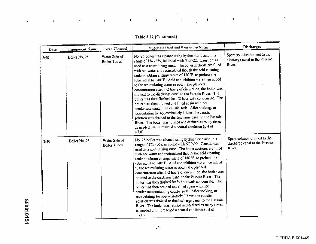
Table 3.22 (Continued)
rDate Eauipment Name Area Cleaned Materials Used and Procetfure Notes . Discharges
2/40 Boiler No. 25 Water Side of No. 25 boiler was cleaned using hydrochloric acid in a Spent solution drained to the
Boiler Tubes range of 1%·5%, inhibited with NEP-22. Caustic was discharge canal to the Passaic
used as a neutralizing rinse. The boiler sections are filled River.with hot water and recirculated though the aeid cleaningtanks to obtain a temperature of 180°F, to preheatlhetube metal to 140°F, Acid and inhibitor were then addedto the recirculating water to obtain the planned -concentration after 1-2 hours of circulation, the boiler wasdrained to the discharge canal to the Passaic Ri\'er. Theboiler "as then flushed for 1/2 hour with condensate. Theboiler was then drained and filled again with hotcondensate containing caustic soda. After soaking, orrecirculating for approximately I hour, the causticsolution was drained to the discharge canal to the PassaicRiver. The boiler was refilled and drained :IS many timesas needed until it reached a neutral condition (pH of,,7.0).
8/40 Boiler No. 25 W:ltcr Side of No. 25 boiler W:lScleaned using hydrochloric acid in a Spent solution drained to theI
Boiler Tubes range of 1% - 5%, inhibited with NEP·22. Caustic was discharge canal to the PassaicIused as a neutralizing rinse. The boiler sections arc filled River.
w·jth hot water and recirculated though the acid cleaningtanks to obtain a tcmperature of (80°F, to preheat thetube metal to 140"F. Acid and inhibitor were then addedto the recirculating water to obtain the plannedconcentration after 1-2 hours of circulation, thc boiler was
Idrained to the discharge canal to the Passaic River. Theboiler was thcn flushed for Y: hour with condensate. Theboilcr was then drained and filled again with hotcondcnsate containing caustic soda. After soaking, orrecirculating for approximately I hour, the causticsolution was drained to the discharge canal to the PassaicRi"er. The boiler was refilled and drained as many timeSas needed until it reached a neutral condition (pH of"7.0). ..
-2-
TIERRA-B-001449

00c.noo~o~c.nf\,)
Table 3.22 (Continued)
Date
4/41
Equipment Name
Boiler No. 25
Area Cleaned
Watcr Sidc ofBoilcr Tubes
Materials Used and Procedure Notes Disch a n!:es
Spent solution drained to thedischarge canal to the PassaicRi\·er.
7/41 Boiler No. 25 Watcr Side ofBoiler Tubcs
No. 25 boiler was cleaned using hydrochloric' acid in arange of 1% - 5%, inhibited with NEP·22. Caustic wasused as a ncutralizing rinse Thc boiler sections are filled
I with hot water and recirculated though thc acid cleaningI
tanks to obtain a tcmpcraturc of 180" F, to preheat thetube metal to 140~F. Acid and inhibitor were then addedto the recirculating \later to obtain the plannedconcentration aftcr )·2 hours of circulation, the boilcr wasdrained to the discharge canal to the Passaic River. Theboiler was thcn nushcd for Y2 hour with condcnsate. Theboiler was then drained and filled again with hotcondensate containing caustic soda. After soaking, orrecirculating for approximately I hour, the causticsolution was drained to the discharge canal to the PassaicRi\·er. The boiler was refilled and drained as many timesas needed until it reached a neutral condition (pH of::7.0).
No, 25 boilcr was cleaned using hydrochloric acid in arange of 1% - 5%, inhibitcd with NEP·22. Caustic wasused as a neutralizing rinse. The boiler sections are filledwith hot water and recirculated though the acid cleaningtanks to obtain a temperature of 180"F, to preheat thetubc metal to 140°F. Acid and inhibitor were then addedto the rccirculating water to obtain the plannedconcentration after 1-2 hours of circulation, the boiler wasdrained to the discharge canal to the Passaic Ri\·er. Theboiler was thcn nushcd for % hour with condensate. Theboiler was then drained and filled again with hotcondensate containing caustic soda. After soaking, orrecirculating for approximately I hour, the causticsolution was drained to the discharge canal to the PassaicRi\'cr. The boiler was refilled and drained as many timesas nceded until it reached a neutral condition (pH of::7.0).
-3-
Spent solution drained to thedischarge canal to the PassaicRiver.
TIERRA-B-001450

coCJ'Ioo....o....enw
Table 3.2~ (Continued)
II Date I Elluinment Name 1 Area Cleaned ) Materials Used and Procedure Notes,
Discharges,
10/41 Boiler No. 25 Water Side of No. 25 boiler was cleaned using hydrochloric acid in a Spent solution drained to theBoiler Tubes range of 1% - 5%, inhibited with NEP-22 Caustic was discharge canal to the Passaic
used as a neutralizing rinse The boiler sections are filled Ri,·er.!
with hot water and recirculated though the ilcid cleaningtanks to obtain a temperature of IgO°F, to preheat the i
tube metal to 140°F. Acid and inhibitor \\ere then addedto the recirculating water to obtain the plannedconcentration after 1-2 hours of circulation, the boiler was I
drained to the discharge canal [0 the Passaic Ri\"er. TheI
boiler was then llushed for 1;2 hour with condensate. The I
boiler was then dmined and filled again with hoti
condensate containing caustic soda. After soaking, orrecirculating for approximately 1hour, the causticsolution was drained to the discharge canal to the PassaicRi,·er. The boiler was refilled and drained as many timesas needed until it reached a neutral condition (pH of I
::::7.0).
1142 Boiler No. 25 Waler Side of No. 25 boiler was cleaned using hydrochloric acid in a Spent solution drained to theBoiler Tubes range of 10/0 - 5%, inhibited with NEP·22. Caustic was discharge canal to the Passaic
used as a neutralizing rinse. The boiler sections arc filled Ri\"cr.with hot water and recirculated though the acid cleaningtanks to obtain a temperature of 1800 F, 10 prehe3tthetube metal to 140°F. Acid and inhibitor were then addedto the recirculating water to obtain the plannedconcenlration after 1-2 hours of circulation, the boiler wasdrained to the discharge canal to the Passaic Ri\'er. Theboiler was then flushed for 1/1hour with condensate. Theboiler was then drained and filled again with hotcondensate containing caustic soda. After soaking, orrecirculating for approximately I hour, the causticsolution was draine.d to the discharge canal to the PassaicRiver. The boiler was refilled and drained as man\' timesas needed ~til it reached a neutral condition (pH Qf::::7.0).
-4-
TIERRA-B-001451

Table 3.22 (Continued)
coCJ'loo..10o..10U'I,1:1.
~ Date '1 Equipment Name 1 Area nf'Jlf!erl I Materials Used and Procedure Notes II Discharges I, ,
2/42 Boiler No. 25 Wnter Side of No. 25 boiler '\lis cleaned using hydrochloric acid in a !I Spent solution drained to theBoiler Tubes range of l% - 5%, inhibited with NEP-22. Caustic was discharge canal to the Passaic
used as a neulralizing rinse. The boiler sections arc filled River.with hot water and recirculated though the acid cleaninglanks to obtain a temperature of 1&0°F, to preheat thetube metal to 140°F. Acid and inhibitor were then addedto the recirculnting water to oblain Ihe plannedconcentration nfter 1-2 hours of circulation, the boiler wasdrained 10 the discharge canal to the Passaic River. Theboiler \\-as then Oushed for ~ hour wilh condensate_ Theboiler WlISthen drained and filled again with hotcondensllle containing caustic soda. Afler soaking, orrecirculaling for approximlllcly I hour, the clluslicsolution was drained to the discharge cllnal 10 the PassaicRiver. The boiler WlISrefilled lInd drllined as many timesas needed until it reached a neutral condition (pH of=7.0).
9/42 Boiler No. 25 Water Side of No. 25 boiler was cleaned using hydrochloric acid in a Spent solution drained to theBoiler Tubes range of 1% - 5%, inhibited with NEP-22. Causlic was discharge canal to the Passaic
used as a nculralizing rinse. The boiler scclions are filled Ri\'er."ilh hot walcr and recirculated Ihough the ncid cleaninglanks to obtain a temperature of 1800 F, to preheat thelube melallo 140'F. Acid and inhibitor wcre then addedto the recirculating waler 10 obtllin the planned
:
concentralion after 1-2 hours of circulalion, Ihe boiler wasdrained 10 Ihe discharge canal to the Passaic Ri\·cr. Theboiler was then flushed for VIhour with condensate. Theboilcr was then drained and filled again with hotcondensate containing caustic soda. After soaking, orrecirculating for approximately I hour, thc causticsolution was dmincd to the discharge canal to the PassaicRiver. The boiler was refilled and drained as many timesas needed until it reached a neutral condition (pH Qf:::7.0)_
-5-
TIERRA-B-001452
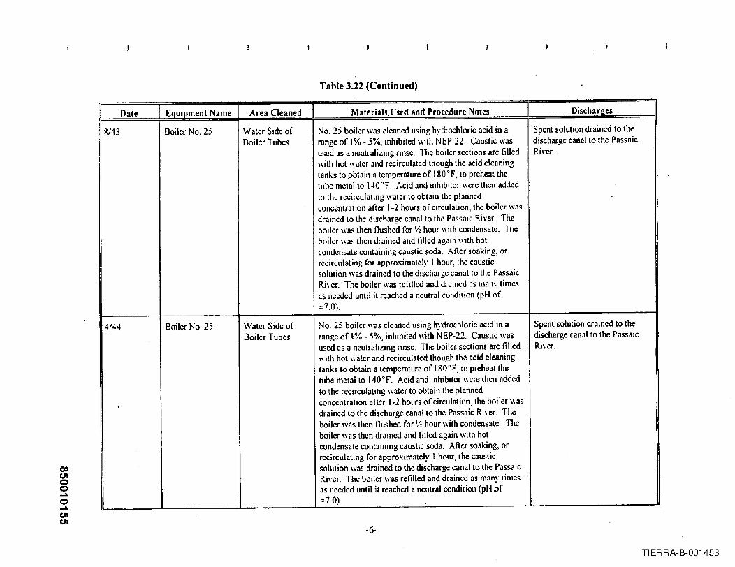
(X)c.noo-o-c.nc.n
Table 3.22 (Continued)
Date ] Equipment Name Area Cleaned Materials, Used and Procedure Notes Discharges
~/43 Boiler No. 25 Watcr Side of No. 25 boiler was cleaned using hydrochloric acid in a Spent solution drained to theBoiler Tubes range of 1%·5%, inhibited with NEP-22. Caustic was discharge canal to the Passaic
used as a neutralizing rinse. The boiler sections arc filled Ri,·cr.with hot water and rccirculated though the acid cleaningtanks to obtain a temperature of IgO°F, to preheat thetube metal to 140°F. Acid and inhibilor were then addedto lhe recirculating waler to obtain the plannedconcentration after 1-2 hours of circulation, thc boiler wasdrained to the discharge canal to the Passaic Ri\"er. Theboiler was then flushed for Yz hour wilh condensate. Theboiler was then drained and filled again ,,,ith hotcondensate containing caustic soda. After soaking, orrecirculating for approximately I hour, the causticsolution was drained to the discharge canal to the PassaicRi"er. The boiler was rcfilled and drained as many timesas needed until it reached a neutral condition (pH of:;7.0)
4/44 Boiler No, 2; Water Side of No. 25 boiler was c1eancd using hydrochloric acid in a Spent solution drained to theBoiler Tubes range of 1% - ;%, inhibited with NEP-22. Caustic was discharge canal to the Passaic
used as a neutralizing rinse. The boiler seclions are filled Ri\'er.with hot water and recirculatcd though the acid cleaningtanks to obtain a temperature of IRO°F, to preheat thetube metal to 140"'F. Acid and inhibitor wcre then addcd
I
to the recirculating water to obtain the planncdconcentration after 1-2 hours of circulation, the boiler wasdrained to the discharge canal to the Passaic River. Theboilcr was then flushed for Ih hour wilh condcnsate. The
I
boiler '\as then drained and filled again with hotcondensate containing caustic soda. After soaking, orrecirculating for approximately I hour, thc causticsolution was drained to the discharge canal to the PassaicRi,'er. The boiler was refilled and drained as many timcsas needed until it reached a neutral condition (pH of:;7.0).
-6-
TIERRA-B-001453

Table 3.22 (Continued)
II Date 'I Equipment Name 1 Area Cleaned 1 Materials Used and Procedure Notes . I Discharges
11/44 Boiler No. 25 Water Side of No. 25 boiler was cleaned using hydrochloric acid in a Spent solution drained to theBoiler Tubes range of 1%- 5%, inhibited with NEP·22. Caustic was discharge canal to the Passaic
used as a neutralizing rinse. The boiler sections are filled Rh'cr.with hot water and recirculated though the acid cleaningtanks to obtain a temperature of 1800 F, to preheat thetube metal to 140°F. Acid and inhibitor were then addedto the recirculating water to obtain the plannedconcentration after 1-2 hours of circulation, the boiler wasdrained to the discharge canal to the Passaic River. The I
boiler was then nushed for ~ hour with condensate. The I
boiler was then drained and filled again with hotcondensate containing caustic soda. After soaking, orrecirculating for approximately I hour, the causticsolution was-drained to the discharge canal to the Passaic ,
River, The boiler was refilled and drained as many timesas needed until it reached a neutral condition (pH of0;7.0).
... --- ----
12/45 Boiler No. 25 Water Side of No. 25 hailer was cleaned using hydrochloric acid in a Spent solution drained to the I
IBoiler Tubes range of 1%- 5%, inhibited with NEp·22. Caustic was discharge canal to the Passaicused as a neutralizing rinse. The boiler sections arc filled Ri\·er.with hot water and recirculated though the acid cleaningtanks to obtain a temperature of 180°F, to preheat thelube metal to 140°F. Acid amI inhibitur wcre then addedto the recirculating water to obtain the plannedconcentration after 1-2 hours of circulation, the boiler wasdrained 10 the discharge canal to the Passaic River. Theboiler was then flushed for ~ hour with condensate. Theboiler was then drained and filled again with hotcondensate containing caustic soda. After soaking, orrecirculating for approximately I hour, the causticsolution was drained to the discharge canal to the PassaicRi\·er. The boiler was refilled and drained as many timesas needed until it reached a neutral condition (pH of0;7,0).
-7-
TIERRA-B-001454
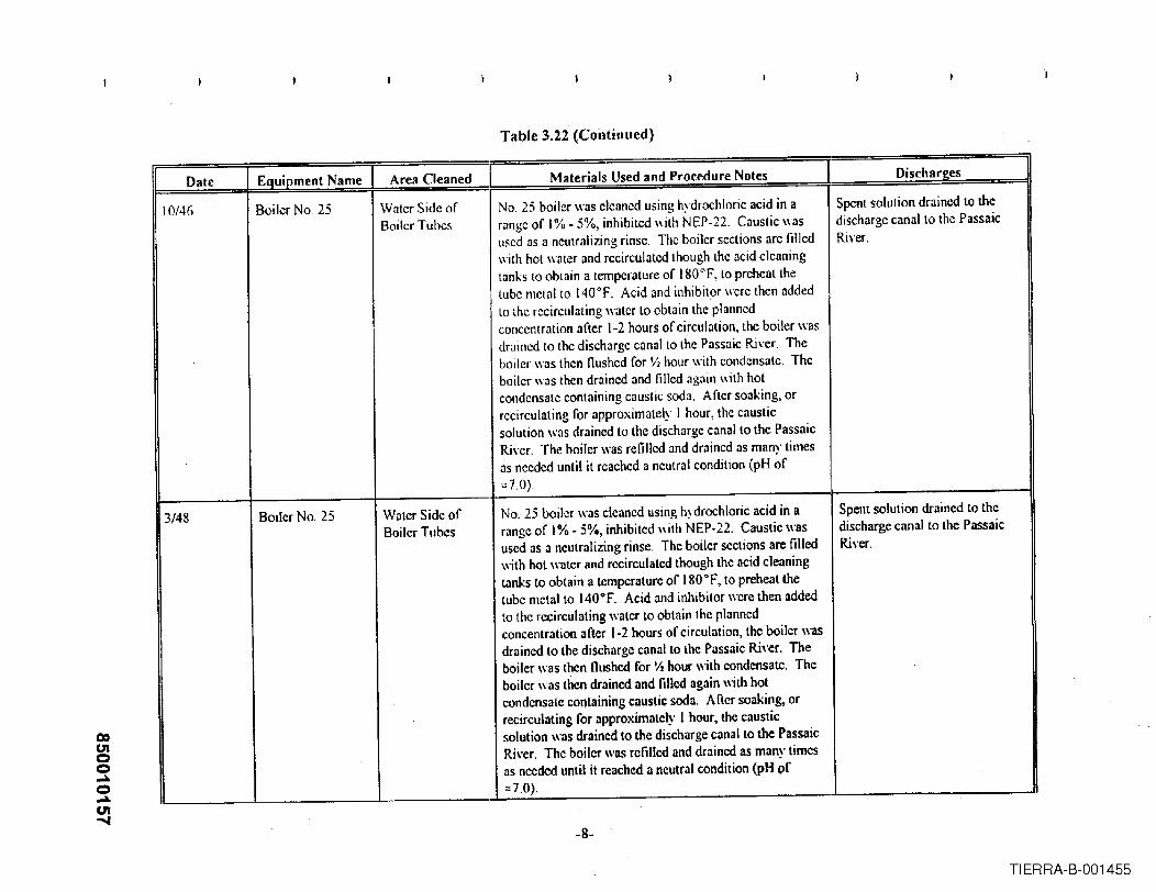
Table 3.22 (Continued)
II I.,
CD01oo-o-01.....
ualt LQiiipmeiit l~ame I*",.A'" Anln.a. ... aterHLS se lInri roce ure otes ISC arges
.rIo"""O ....... ''''a.' ....... I
10/46 Boiler No 25 Water Side of No, 25 boiler was cleaned using hydrochloric acid in a Spent solulion drained to theBoiler Tubes range of 1% - 5%, inhibited wilh NEP-22. Causlic was discharge canal to the Passaic
used as a neulralizing rinse, The boiler seclions arc filled Ri,'er.wilh hot water and recirculated though the acid cleaningtanks 10 obtain a temperature of 180°F, 10 preheat thetube metlll to 140°F. Acid and inhibitor were then addedto the recirculating waler La oblain the plannedconcentration after 1-2 hours of circulation, the boiler wasdfilined to the discharge canal 10 the Passaic River. Theboiler was then nushed for 1/2 hour with condensate. Theboiler was then drained and lilled again \\"ilhhotcondensate containing causlic soda, After soaking, orrecirculating for approximately I hour, the causticsolution was drained to the discharge canal to the PassaicRi\'er. The boiler was refilled and drained as many timesas nceded until it rcached a neutral condition (pH of:.:7.0).
3/48 Boiler No. 25 Water Side of No. 25 boiler was cleaned using hydrochloric acid in a I Spent solution drained 10 theBoiler Tubes range of 1% - 5%, inhibited with NEP·22. Caustic was discharge canal to the Passaic
used as a neulralizing rinse. The boiler sections are filled River.with hot water and recirculated though the acid cleaningtanks to obtain a lemperature of IRO°F, to preheat thetube metal to 140°F. Acid and inhibitor werc then addedto the recirculating water to obtain the plannedconcentration after 1-2 hours of circulation, the boiler wasdrained 10 the discharge canal to the Passaic Ri,·er. Theboiler was then flushed for 'Ii hour with condensate. Theboiler was then drained and filled again with hotcondensate containing caustic soda. Afier soaking, orrecirculating for approximately I hour, the causticsolution was drained to the discharge canal 10 the PassaicRiver. The boiler was refilled and drained as many timesas needed until it reached a neutral condition (pH pf",7.0).
p d N O· hA M . I II rI
-8-
TIERRA-B-001455

coc.noo...ll.o...ll.C1ICO
Table 3.2~ (Continued)
II Date ] Equipment Name J Area Cleaned Materials Used and Procedure Notes Dischan!es
4/49 Boiter No. 25 Water Side or No. 25 boiler was cleaned using hydrochloric acid in a Spent solution drained to theBoiler Tubes mnge or 1% - 5%, inhibited with NEP-22. Caustic was discharge canal to the Passaic
used as a neutralizing rinsc. The boiler scctions are filled River.with hot water and recirculated though the acid cleaningtanks to obtain a temperaturc or J 80°F, to preheat thetube mctalto 140°F. Acid and inhibitor wcre then addedto the recirculating water to obtain the planned
. concentration after 1-2 hours or circulation, the boiler wasdr:Jined to the discharge canal to the Passaic Rh'er. Theboiler was thcn flushed ror Yz hour with condensate. Theboiler was thcn drained and fillcd again with hotcondensate containing caustic soda. Aftcr soaking, orrecirculating ror approximately I hour, the causticsolution was drained to the discharge canal to the PassaicRi\·cr. The boiler was refilled and drained as many timesas nceded until it rcached a neutral condition (pH or0:7.0).
5/50 Boiler No. 25 Water Side or No. 25 boiler was cleaned using hydrochloric acid in a Spent solution drained to theBoiler Tubes range or 1% - 5%, inhibited with NEP-22. Caustic was discharge canal to the Passaic
used as a neutralizing rinse. The boiler sections are tilled Ri\'er.with hot water and recirculated though the acid cleaningtanks to obtain a temperature of IgO°F, to preheat thetube metal to 140°F. Acid and inhibitor \lcre thcn addedto the recirculating water to obtain the plalUlcdconcentration after 1-2 hours of circulation, the boiler wasdrained to the discharge canal to the Passaic River. Theboiler was then flushed for 'h hour \lith condensate. Theboiler was then drained and filled again with hotcondensate containing caustic soda. After soaking, orrecirculating for approximately I hour, the causticsolution was drainc,d to the discharge canal to the PassaicRivcr. The boiler was retilled and drained as manv timesas needed ~nlil it reached a neutral condition (pH ~f:::7.0) .
-9-
TIERRA-B-001456

coc.noo....o....c.ncg
Table 3.22 (Continued)
11 Date ] Equipment Name 1 Area Cleaned 'I Materials Used and Procedure Notes I Discharges :=J9/51 Boiler No. 25 Water Side of No. 25 boiler \\'lIS cleaned using hydrochloric acid in a Spent solution drained to the
Boiler Tubes range of 1% - 5%, inhibited with NEP-22. Caustic was discharge canal to the Passaicused as a neutralizing rinse, The boiler sections are filled River.with hot water and recirculated though the acid cleaningtanks to obtain a temperature of 180°F, to preheat thetube metal to 140°F. Acid and inhibitor were then addedto the recirculating water to obtain the plannedconcentration after 1-2 hours of circulation, the boiler wasdrained to the discharge canal 10 the Passaic Ri"er. Theboiler \las Ihen flushed for ;12 hour with condensate. Theboiler \Ias then drained and filled again with hotcondensate containing caustic soda, After soaking, orrecirculating for approximately I hour, Ihe causticsolution was drained to the discharge canal to the PassaicRiver. The boiler was refilled and drained as many timesas needed until it reached a neutral condition (pH of::::7.0).
6/53 Boilcr No. 25 Watcr Side of No. 25 boiler was cleaned using hydrochloric acid in a Spent solution draincd to theBoiler Tubcs range of 10/0• 5%, inhibited with NEP-22. Caustic was discharge canal to the Passaic
used as a neutralizing rinse. The beiler sections are filled River.with hot water and recirculated though the acid cleaningtanks to obtain a temperature of 180°F, to preheat thelUbemctal to 140°F. Acid and inhibitor wcre then addedto (hc recirculating water to obtain the plannedconcentration after 1-2 hours of circulation, the boiler wasdrained 10 the discharge canal to the Passaic River. Theboiler was thcn flushed for Y2 hour with condensate. Theboiler was then drained and filled again with hotcondensate containing caustic soda. Arter soaking, or i
recirculating for approximately 1 hour, the causticsolution was drilined to the discharge canal to the PassaicRi,"er. The boiler was refilled and drained as many timesas needed until it reached a neutral condition (pH of:;;7.0).
-10-
TIERRA-B-001457

Table 3.22 (Continued)
co01oo...a.o...a.eno
I Date I Equipment Name I Area Cleaned ] J\faterials ysed and Procedure Notes Discharees
2/55 Boiler No. 25 Water Side of No, 25 boiler \\'as cleaned using hydrochloric acid in a Spent solution drained to theBoiler Tubes range of 1% • 5%, inhibited with NEP-22, Caustic was discharge canal to the Passaic
used as a neutralizing rinse. The boiler sections are filled Ri\'er.with hot water and recirculated though the acid cleaningtanks to obtain a temperature of 180°F, to preheat thetube metal to 140°F. Acid and inhibitor were then addedto the recirculating water 10 obtain the plannedconcentration after 1-2 hours of circulation, the boiler was
idrained to the discharge cnnallo Ihe Passaic Ri,'er. Theboiler was then Oushed for Y2 hour \\'ilh condensate. Theboiler was then drained and filled again with hotcondensate containing caustic soda, After soaking, orrecirculating for approximately I hour, the causticsolution was drained to the discharge canal to the PassaicRi\'er. The boiler was refilled and drained as many timesas needed until it reached a neutral condition (pH of;:;7.0).
12/57 Boiler No. 25 Water Side of No. 25 boiler Wl!5 cleaned using hydrochloric acid in a Spent solution drained to theBoiler Tubes range of 1% - 5%, inhibited with NEP-22. Caustic was discharge canal to the Passaic
used as a neutralizing rinse The boiler sections are filled River.with hot water and recirculated though the acid cleaningtanks to obtain a temperature of 1800 F, to preheat thelube mclalto 140nF. Acid and inhibilor were then addedto the recirculating water to oblain Ihe plarUledconcentration after 1-2 hours of circulation, the boiler wasdrained 10 the discharge canal to the Passaic Ri\'er. Theboiler was then flushed for Y2hour with condensate. Theboiler was then drained and filled again with hotcondensate containing caustic soda. After soaking, orrecirculating for approximately I hour, the causticsolution was drained to the discharge canal to the PassaicRiver. The boiler was refilled and drained as many timesas nccded until it reached a neutral condition (pH of:::7,0).
-11-
TIERRA-B-001458

co01oC)....C)....Q)....
Table 3.22 (Continued). -,..
Date EQuipment Name ] Area Cleaned . Materials Used and Procedure Notes . Discharges
3/15/72 Boiler No. 25 Water Side of The boiler was cleaned using Vertan 675 (letra- Spent solution trucked off sileoBoiler Tubes ammonium ethylenediamine tetra acetic acid), an alkaline
copper remO\'alprocess patented by the Dow ChemicalCo. The boiler\\'as lilled with the A-124 inhibitor, firedand cooled at a frequency to cause the boiler pressure tooscillate between 50 and 150 psi, thus causing thecleaning solution to naturally circulate in the boiler.Additional chemical was injected when necessa~" tomaintain the required parameters. When iron and Vertanconcentrations leyeled out, indicating completion ortheiron remO\"alphase, the liring ccased and the boiler wascooled to approximately 170 'F. Air was then injectedinto \'arious connections in the lower headers to effectcopper removal and passinlte the newly cleaned metalsurfaces. When copper nllues le"e1edout the air injectionstopped and the boiler drnined to the discharge canal, andthen gi\'en a rinse with hot ((80'F) condensate.
Chemical Used: 78,400 Ibs of Vertan 615 LMetals remo\"ed: Iron - 3,664 Ibs, Copper - 325 lbs
-12-
TIERRA-B-001459.

Table 3.22 (Continued)
II 1 Equipment Name 1-
Date Area Cleaned Materials Used and Procedure Notes DischareesI
10/2';,/72 Boiler No. 25 Water Side of The boiler was cleaned by Halliburton Industrial Cleaning Spent solution \\as e\"Jporat~d inBoiler Tubes Seryice using the CitroSolY process. The boiler was No 26 Boiler.
heated, then filled with a 3% solution of ammoniatcdcitric acid at approximately 200 0 F, with an a"erngc pH of4.0. When iron concentration and acid concentrationle"e1ed out, indicating completion of the iron remO\'al i
phase, the boiler was allowed to cool to 150" F, for thecopper remo-i'aland metal passi\'ation stage. AnhydrousunmlOniawas then added to the recirculating pump
,
suction to raise the pH to 9.0. A sodium nitrite solutionwas pumped to the boiler. Additional anhydrousammonia was pumped to the system to raise the pH to10.0. When the copper concentrations IC\'e1edout, theboiler was drained.
Chemicals used wcre: 10,300 Ibs citric acid, 300 gals. iII
ammonium hydroxide, 9 gals Rodine 31A inhibitor and800 Ibs sodium nitrite. The soh'ent uYcragcd205 OF, 3.3pH and l2% citric acid for the iron phase. The copperremoyal phase JYeragcd a 9.1 pH and 135OF.Approximately 1,130 Ibs Fe and 30 Ibs Cu were removed.
00c.nco-o~mN
-13-
TIERRA-B-001460
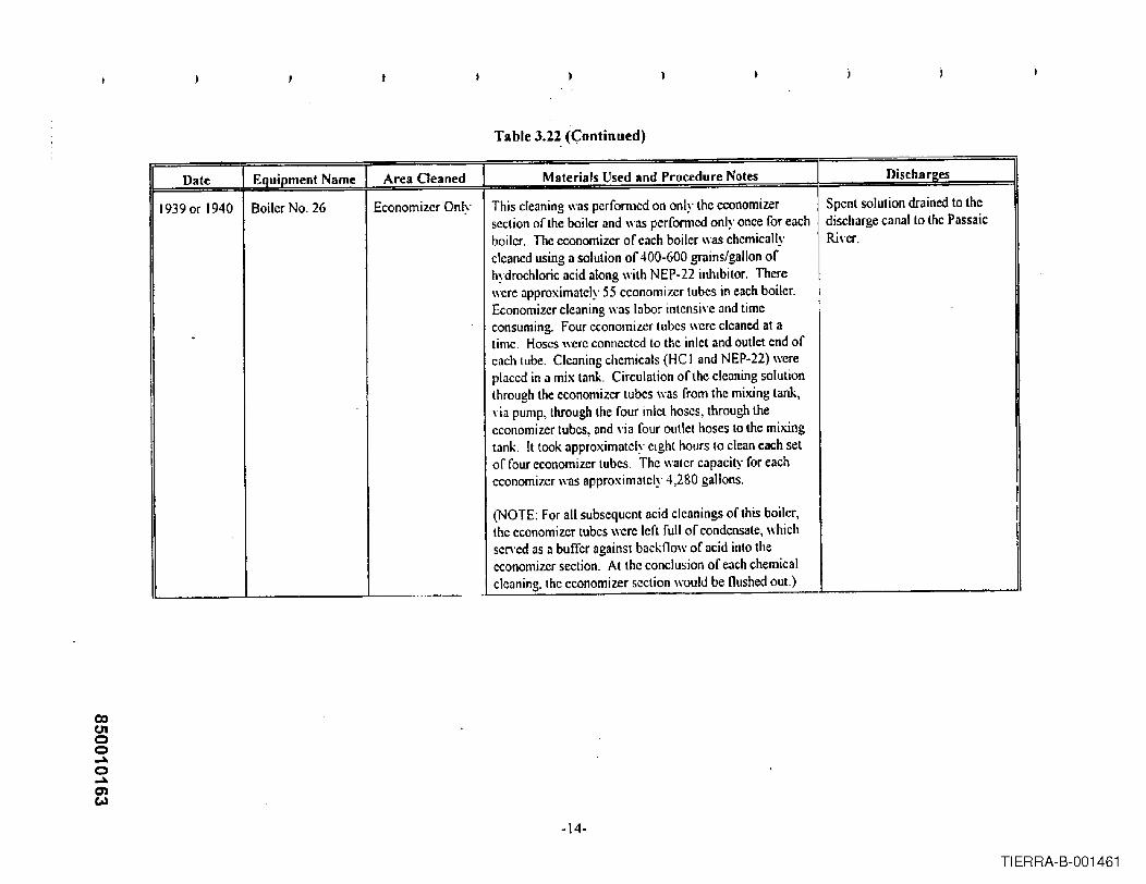
Table 3.22.«:ontinued)
II Date I Equipment Name 'I Area OPII nprl I Materials Used and Procedure Notes I: DischargesI
1939 or 1940 Boiler No. 26 Economizer Only This cleaning was pcrfonned on only the economizer Spent solution drained to thesection of the boiler i1nd was performed only once for each discharge canal 10 the Passaicboiler. The economizer of each boiler was chemically River.cleaned using a solution of 400-600 grains/gallon of Ihydrochloric acid along with NEP-22 inhibitor. There !were approximately 55 economizer tubes in each boiler.Economizer cleaning wns Inbor intellsi\'e and time
- consuming. Four economizer tubes were cleaned at atime. Hoses were connected to the inlet and outlet end ofcilch lube. Clenning chemicnls (HC I ilnd NEP·22) wereplaced in n mix tank. Circulation of the cleaning solutionthrough the economizer tubes was from the mixing tank,\iil pump, through the four inlct hoses, through theeconomizer tubes, and "ia four outlet hoses 10 the mixingtank. It took approximately eight hours to clean each setof four economizer tuhcs. The water capacily for eacheconomizer was approximately 4,280 gallons.
(NOTE: For all subsequent acid c1eanings of this boiler,the economizer tubes were left full of condensate, whichser.ed as a buffer against backllo\\' 'of acid into theeconomizer section. At the conclusion of each chemicalcleaning, the economizer section would be flushed OUI.)
CD0'1oo......o......0)(..)
-14-
TIERRA-B-001461

Table 3.22. (Continued)
II Date I Equipment Name -, Area Cleaned 1 Materials Used and Procedure Notes I n:r""' ..........ft.a..I ....·., ...."a.·6~.,
3/40 Boiler No. 26 Water Side of No. 26 boiler was cleaned using hydrochloric acid in a Spent solution drained to theBoiler Tubes range of 1%· 5%, inhibited with NEP-22 .. Caustic was discharge canal to the Passaic
used as a neutralizing rinse. The boiler sections are filled Ri,·er.with hot waler and recirculated though the acid cleaningtanks to obtain a tcmperature of 180°F, to preheat thetube mctal to 1400F. Acid and inhibitor were then addedto the recirculaling water to obtain the planned -
concentration nfter 1-2 hours of circulation, Ihe boiler wasdrained to the discharge canal to the Passaic River. Theboiler was then flushed for Y2 hour with condensate. Theboiler was then drained and filled again wiLh hotcondensate containing causLic soda. After soaking, orrecirculating for approximately Ihour, the causticsolution was drained Lothe discharge canal to the PassaicRj\'l~r. The boiler was refilled and drained as many timesas necded until il reached a neutral condition (pH of,"7.0).
9/40 Boiler No. 26 Water Side of No. 26 boiler was cleaned using hydrochloric acid in a Spent solution drained to theBoiler Tubes range of 1%· 5%, inhibited with NEP-22. Caustic was discharge canal to the Passaic
used as a neutralizing rinse. The boiler sections arc filled River.with hot water and recirculated though the acid cleaningtanks to obtain a tcmperature of 180°F, to preheat thetube metal to 140'T Acid and inhibitor were then addedto the recirculating wilter to obtain the plannedconcentration after 1-2 hours of circulation, the boiler wasdrained to the discharge canal to the Passaic River. Theboiler \\'as then flushed for 1;2 hour with condensate. Theboiler was Ihen drained and filled again with hotcondensate containing caustic soda. After soaking, orrecirculating for approximatcly I hour, the causticsolution was drained to the discharge canal to the PassaicRi,·cr. The boiler was refillcd and drained as many times
II
as nceded until it reached a neutral condition (pH,ofI , :::7.0).
-15-
TIERRA-B-001462

coU'Ioo~o...0)U'I
Table 3.22 (Continued)
I Date Equipment Name Area Cleaned Material.s Used and Procedure Notes Discharl!;es-- ---
3/41 Boiler No_ 26 Wilter Side of No. 26 boiler was cleaned using hydrochloric acid in a Spent solution drained to theBoiler Tubes range of 1% - 5%, inhibited with NEP-22. Caustic was discharge canal to the Passaic
used as a neutralizing rinse. The boiler sections arc filled Ri\'cr.with hot \rater and recirculated though the acid cleaningtanks to obtain a temperature of 1800 F, to preheat thetube metal to 140'F Acid ilnd inhibitor were then addedto the recirculating water to obtain the plannedconcentration after 1-2 hours of circulation, the boiler was
, drained 10 Ihe discharge canal to the Passaic Ri\·er. Theboiler \I'as then flushed for 'Il hour wilh condensate. Theboiler was then drained and filled again with hotcondensate containing caustic soda, After soaking, orrecirculating for ..pproximately I hour, the causticsolution was drained to the discharge canal to the PassaicRi\·er. The boiler WilSrefilled and drained as many timesas needed until it reached a neutral condition (pH of:;7.0).
6/41 Boiler No. 26 Water Side of No_26 boiler WilScleaned using hydrochloric acid in a Spent solution drained 10 theBoiler Tubes range of 1%- 5%, inhibiled with NEP-22, Caustic was discharge canal to the Passaic
used as a neulralizing rinse. The boiler sections are filled River.with hot water nnd recirculated though the acid cleaningtanks to obtain a temperature of 1800 F, to preheat thetube metal to 140"F Acid nnd inhibitor were then added
I to the recirculating water to obtain the pl..nncdconcentration nftcr 1-2 hours of circulation, the boilcr wnsdrained to the discharge canal to the Passaic Rivcr. Thcboiler was then flushed for '11 hour with condensate. The
Iboiler was then drained and filled again with hotcondensate containing caustic soda. After soaking, or
!
recirculating for approximately I hour, the caustic, solution was drained to the discharge cnnalto the Passaic
!I
Ri\'er. The boiler was refilled and drnined as many timesas needed until it reached a neutral condition (pH of:::7.0).
-16-
TIERRA-B-001463

Table 3.22 (Continued)
I Date 1 Equipment Name Area Cleaned Materials Used and Procedure Notes . ] Discharges
R/41 Boiler No. 26 Water Side of No. 26 bOIlerwas cleaned using hydrochloric acid in a Spent solution drained to theBoiler Tubes range of I 'Yo- 5%, inhibited with NEP-22. Caustic was discharge canal to the Passaic
used as a nell(ralizing rinse. The boiler sections arc filled Rj\·er.with hot water and recirculated though the acid cleaningtanks to obtain a temperature of l80"F, to preheat thelube metal to 140 T Acid and inhibitor were then addedto the recirculating water to obtain Ihe plannedconcentralion after 1·2 hours of circulation, the boiler wasdrained to the discharge canal to the Passaic River. Theboiler was then nushed for Y2 hour with condensate. Theboiler was thcn drained and filled again with hotcondensate containing caustic soda. After soaking, or
Irecirculating for approx.imately Ihour, the causticsolution was drained to the discharge canal to the PassaicRiver. The boiler was refilled and drained as many timesas needed until it reached a neutral condition (pH of;:;;70).
3/42 Boiler No. 26 Water Side of No. 26 boiler was cleaned using hydrochloric acid in a Spent solution drained to theBoiler Tubes range of 1% - 5%, inhibited with NEP-22. Caustic was discharge canal to the Passaic
used as a neutralizing rinse. The boiler sections are fillcd Rivcr.with hot wilter ilod rccirculatcd though the acid cleaninglanks to obtain a temperature of 180"F, to prehcat thetube Illetllito 140" F. Acid and inhibitor "'ere then addedto Ihe rccircuillting waler to obtain the plannedconcentration lifter 1-2 hours of circulation, the boiler wasdrained to the discharge canal to the Passaic River. Theboiler was then nushcd for 1/2 hour with condensate. The I
boiler was then drained and filled again with hotI
I
condensate contllining caustic soda. After soaking, orrecirculating for approx.imately Ihour, the causticsolution was drained to the discharge cllMlto the PassaicRi\cr. The boiler WlIS refilled and drained as many timesas needed until it reached 11 neutral condition (pH of;:;;7.0).
-17-
TIERRA-B-001464

CD(J'Ioo-"o-"C).....
Table 3".22-{Continued)
Dale Equipment Name Area Cleaned Materials Used and Procedure Notes Discharees
10/42 Boilcr No. 26 Walcr Side of No, 26 boiler was c1caned using hydrochlon"c acid in a Spent solution drained to theBoiler Tubes range of 1% - 5%, inhibiled with NEP-22_ Caustic was discharge canal to the Passaic
used as a neutralizing rinse. The boiler sections are filled River.\\-ith hot water and recirculated though the ncid cleaningtnnks to obtnin a tempernture of IllO°F, to preheat thelube metnl to 140<>F. Acid nnd inhibitor ,\-ere then addedto the rccirculnling willer to oblain the plannedconcenlmtion nfter 1-2 hours of circulalion, lhe boiler wasdrained lo Ihe dischnrgc canal to the Passaic Ri\'er. Theboiler WilSthen flushed for III hour with condensate. Theboiler was then drained .md filled agilin "ith hotcondensale containing caustic soda, After soaking, orrecirculating for approximately I hour, the causticsolulion "-as drained to the discharge ennni to the PnssnicRj,'cr. The boiler was refilled and drnined ns mnny times,as needed until it reached a ncutrJI condition (pH of,
, :::7.0).. -- . -_ .. -_._- .._- --- - --,
2/43 Boiler No_ 26 Wnler Side of No. 26 boiler "as c1eJned using hydrochloric acid in a Spent solulion drained to theI Boiler Tubes range of 1% - 5%, inhibited "ith NEP-22. Caustic "ns discharge canal to the Passaic!
used as a neutralizing rinse. The boiler seclions are filled River.
! with hot water and recirculated though the acid cleaningtanks to obtain a temperalure of IgO°F, to preheat thelube metal to 140"r:. Acid and inhibitor ,\ere then nddcdto the recirculating water to oblain the plannedconcentration nftcr 1·2 hours of circulntion, the boiler wasdraincd to the disehnrge canal to the Passaic Ri'"er. Theboiler was then nushed for '12 hour with condensate. Theboiler was then drained and filled again with hot
, condensate containing caustic soda_ After soaking, orrecirculating for approximntely I hour, the cnusticsolution was drnined to the discharge canal to the PassaicRi,·cr. The boiler was relilled and drnined as many timesas nccded until il renchcd J neutral condition (pl-lof:::7.0) .
-18-
TIERRA-B-001465

coC1Ioo~o~0)CO
Table 3.~2 (Continued)
IIOate 1 Equipment Name 1 Area Cleaned I Materials Used and Procedure Notes 1 Diuharpf's
11/43 Boiler No. 26 Water Side of No, 26 boiler was c!cilned using hydrochloric acid in a Spent solution drained to theBoiler Tubes range of 1% - 5%, inhibited with NEP·22. Caustic was discharge canal to the Passaic
used as a neutralizing rinse, The boiler sections are filled R.i\·cr.with hot water and recirculilted though the acid cleaningtanks to obtain a temperature of 180 °F, to preheat thctube metal to 140°F, Acid and inhibitor were then addedto the recirculating \\·'lIer·to obtain the planned
. concentration after 1·2 hours of circulation, the boiler wasdrained to the discharge canal to the Passaic Riyer. Theboiler \\'as then flushed for Y, hour with condensate. Theboiler was then drained and filled again with hotcondensate containing caustic soda. Arter soaking, orrecirculating for approximately Ihour, the causticsolution was drained to the discharge canal to the PassaicR.iyer. The boiler was refilled and drained as many times ;
as needed until it reached a neutral condition (pH of",7.0).
7/44 Boiler No. 26 Water Side of No. 26 boiler was cleaned using hydrochloric acid in a I Spent solution drained to theBoiler Tubes range of 1% - 5%, inhibited with NEP·22. Caustic was discharge canal to the Passaic
used us a neutralizing rinse. The boiler sections are filled Ri\"er.\\'ith hot water and recirculated though the acid cleaningtanks to obtain a temperature of 180 ° F, to preheat thetube metal to 140°F. Acid and inhibitor were then addedto the recirculating water to obtain the planned
:
concentration after 1-2 hours of circulation, the boiler wasdrained to the discharge canal to the Passaic Ri\"er. Theboiler was then nushed for Y2 hour with condensate. Theboiler was then drained and filled again with hotcondensate containing caustic soda. After soaking, or I
recirculating for approximately I hour, the causticIsolution was drail)ed to the discharge canal to the Passaic ,
Rj\"er. The boiler was refilled and drained as many limesas needed until it reached a neutral condition (pH of
I'" 7.0).
..
-19-
TIERRA-B-001466

coUIoo....o....0')CO
}
Table 3.22 (Continued)
n. • Ie :JIU&1.e , Lqulpmen .. l ....ame ....~4 .p".JIn~ ... ster!lI.s ~Sl" an roce ure otes ISC ar2esI ~ 1I." .... P. _ .............. '-- I . _.
2/45 Boiler No. 26 \Vater Side of No. 26 boiler '\\'as cleaned using hydrochloric acid in a Spent solution drained to the
Boiler Tubes range of 1%- 5%, inhibited with NEP-22. Caustic was discharge canal to the Passaicused as a neutralizing rinse. The boiler sections are lilled Ri\'er.with hot water and recirculated though the acid cleaningtanks to obtain a temperature of 1800 F. to preheat thetube metal to 140"F. Acid and inhibitor were then addedto the recirculating water to obtain lhe plannedconccntralion after 1-2 hours of circulation, the boiler wasdrained to the discharge canallo the Passaic Ri,'er. Theboiler was then nushed for 112 hour with condensate. Theboiler was then drained and filled again \\'ith hotcondensate containing caustic soda. After soaking, orrecirculating for approximately I hour, the caustic
,
solution was drnined to the discharge eanalto the Passaic I
Ri\'er. The boiler was refilled and drained as many times!
as needed until it reached a neutral condition (pH of i
:::7.0).
9/45 Boiler No. 26 Water Side of No. 26 boiler ,\as cleaned using hydrochloric acid in a Spent solution drained to the
Boiler Tubes range of 1% - 5%, inhibited with NEP-22_ Caustic was discharge canal to the Passaicused ilS a neutralizing rinse. The boiler sections are filled I
Ri\"er.with hot water and recirculated though the acid cleaning I
tanks to obtain a temperature of 1800 F, to preheat thetube metal to 140~F. Acid and inhibitor were then addedto the recirculating \\ater to obtain the plannedconcentration after 1-2 hours of circulation, the boiler wasdrained to the discharge canal to the Passaic Ri,·er. Theboiler was then flushed for '12 hour with condensate. Theboiler was then drained and filled again with hotcondensate containing caustic soda. After soaking, orrecirculating for approximately I hour, the causticsolution was drained to the discharge canal to the PassaicRi\'er. The boiler was refilled and drained as many timesas needed until it reached a neutral condition (pH of"'7.0). .
rl M "11Ilt dP d N D" h
-20-
TIERRA-B-001467

co01oo~o~~o
Table 3.22 (Continued)
II Date ]Eql;ipment Name -, Area Cleaned Materials Used llnd ProC'prlllrp Notes Discha r2,es2/47 Boiler No. 26 Watcr Sidc of No. 26 boilcr was cleaned using hydrochloric acid in a Spent solution drained to the
Boiler Tubcs rangc of 1%· 5%, inhibited with NEP-22. Caustic was discharge eanalto the Passaicuscd as a neutralizing rinse. Thc boiler scctions are filled RiYcr.with hot water and rccirculatcd though the acid cleaningtanks to obtain a temperature of 180°F, to preheat thetube metal 10 1400 F Acid and inhibitor wcre then addcdto the recirculating water to obtain the plannedconcentration after 1-2 hours of circulation, the boiler wasdrained to the dischargc canal to the Passaic RiYcr. Theboiler \'as then nushed for ~ hour with condensate. Theboilcr was then drained and filled again with hotcondensatc containing caustic soda, After soaking, orrecirculating for approximalcly I hour, the causticsolution was drained to the discharge canal to the PassaicRi"cr. The boiler was refilled and drained as many timesas necded until it reachcd a neutral condition (pH of:::7.0).
4/48 Boiler No. 26 Water Side of No. 26 boiler w~s cleaned using hydrochloric acid in a Spent solution drained to theBoiler Tubes range of 1% - 5%, inhibited with NEP-22. Caustic was discharge canal to the Passaic
used as a neutralizing rinse. The boiler sections are filled Rh·er.with hot water and recirculated though the aeid cleaningtanks to oblain a temperature of 180°F, to preheat thetubc metal to 140"F. Acid and inhibitor wcre then added10 the recirculating water to obtain the planncdconcentration after 1-2 hours of circulation, the boiler wasdrained to the discharge eanalto the Passaic Ri,·cr. Theboiler was thcn llushcd for 'h hour with condensate. Theboiler was then drained and filled again with hotcondensate containing caustic soda. After soaking, orrccirculating for approximately I hour, the caustic
, solution was draincd to the discharge canal to the PassaicRiver. The boiler was relillcd and drained as many times
i as nceded until it reached a neutral condition (pH Qf~ ,,7.0).
-21-
TIERRA-B-001468

00U1oQ.-Q.-........-
Table 3.22 (Continued)
II Date 1 EQuioment Name I Area Cleaned I Materials Used alld Procedure Notes . I Discharges, ,. . -
4/50 Boiler No. 26 Water Side of No. 26 boiler was cleaned using hydrochloric acid in a SPCllt solution drained to theBoiler Tubes rangc of 1%.5%, inhibited with NEP·22. Caustic was discharge caMlto the Passaic
used as a neutralizing rinse. Thc boiler sections are filled Ri\·cr.with hot water and recirculated though the acid cleaningtanks to obtain a temperature of 1800 F, to preheat thetube metal to 1400 F. Aeid and inhibitor were then addedto the recirculating \\ilter 10 obtainlhe plannedconcentration after 1-2 hours of circulation, the boiler wasdraincd La thc discharge canal to the Passaic Ri\·cr. Theboiler was then flushed for '/2 hour \\iLh condensaLe. Theboiler was Lhen drained and filled again with hotcondensate containing caustic soda. After soaking, orrecirculating for approximately I hour, the causticsolution was drained to the discharge canal to the PassaicRi\cr. The boiler was refilled and drained as many timesas nceded until it reached a neutral condition (pH of"7.0).
8/52 Boiler No. 16 WOlLerSide of No. 26 boiler was cleaned using hydrochloric acid in a Spent solution drained to theBoiler Tubes range of 1% - 5%, inhibitcd with NEP-21. Caustic was discharge canal to the Passaic
used &IS a neutralizing rinse. The boiler sections are filled Rivcr.\\'ith hot water and recircul<ed though the acid cleaningtanks to oblain a temperature of 1800 F, to preheat thelube melalto 140°F. Acid and inhibitor were then addedto the recirculating watcr to obt&linthe plannedconcentration after 1-2 hours of eircul<ion, the boiler wasdrained 10 the discharge canal to the Passaic Ri,·er. Theboiler W&lSthen flushed for 'l2 hour "ilh condcnsate. Theboiler was then drained and filled again with hotcondensate containing caustic soda. After soaking, orrccirculating for approximately I hour, the causticsolution was drained to the discharge canal to the PassaicRi\·cr. The boiler was refilled and drained as many timesas needed until it reached a neutral condition (pH of0:7.0) . _ . _ ..... - ,.
-22-
TIERRA-B-001469

CDUIoo...o...~N
}
Table 3.22 (Continued)
II Date ] Equipment Na~.e ] Area Cleaned 1 Materials Used and Procedure Notes.,
Dischar~es.-
3/54 Boiler No. 26 Water Side of No. 26 boiler was cleaned using hydrochloric acid in a Spent solution drained to theBoiler Tubes range of 1%- 5%, inhibited with NEp-22. Caustic was dischargc canal to the Passaic
used as il neutralizing rinse. The boiler sections arc filled Ri,·cr.with hot \Iater and recirculated though the acid cleaningtanks to obtain a temperature of IgO°F, to preheat thetube metal to 140°F. Acid and inhibitor \\crc then addedto the recirculating water to obtain the plannedconcentration after 1-2 hours of circulation, the boiler wasdrained to the dischargc canal to the Passaic Ri,·er. Theboiler \Ias then Ilushed for Y2 hour with condensate. Thcboiler "as then draincd and filled again with hotcondensate containing caustic soda. After soaking, orrccirculating for approximately I hour, the causticsolution ",as draincd to the discharge canal to thc PassaicRi\"cr. The boiler ",as refilled and drained as many timesas needed until it reached a neutral condition (pH of:::7.0).
4/5Cl Boiler No. 26 Water Side of No. 26 boiler wus cleaned using hydrochloric ucid in a Spent solution drained to theBoiler Tubes range of 1%- 5%, inhibited with N EP-22. Caustic was dischurge cunal to the Passaic
used as a neutralizing rinse. The boiler sections arc fillcd River.with hot wuter and recirculated though the acid cleaningtanks to oblain a temperature of 180 OF, to preheat thetube metal to 1400 F. Acid and inhibitor \\crc thcn addedlO the recirculating water to obtain the plmmedconcentration after 1-2 hours of circulation, thc boiler wasdrained to the discharge canal to thc Passuic River. Theboiler \\'as then Ilushcd for '/2 hour with condensate. Theboiler was then drained and fillcd again with hotcondensute comaining caustic soda. After soaking, or
!
recirculating for upproximutely Ihour, the CJusticsolution was drained to the dischargc canal to the PassaicRi,·cr. The boiler was retilled and drained as many timesas needed until it reached a neutral condition (pH of:::7.0) .
..
-23-
TIERRA-B-001470

Table 3.22 (Continued)
II Date 1 Equipment Name 1 Area Cleaned Materials Used and Procedure Notes Discharges
3/4/58 Boiler No. 26 Water Side of No. 26 boiler was cleaned using hydrochloric acid in a Spent solution drained to theBoiler Tubes range of 1% - 5%, inhibited with NEP-22. Caustic was discharge canal to the Passaic
used as a neutralizing rinse. The boiler scctions are filled River.with hot water and recirculated though the acid cleaningtanks to obtain a temperature of I&0OF, to preheat thelube metal to 140"F, Acid and inhibitor wcre then addedto the recirculating water to obtain the planned .concentration after 1-2 hours of circulation, the boiler was. drained to the discharge canal to the Passnic R..i\'er. Theboiler was then nushed for 1/2 hour with condensate. Theboiler wns then drained and filled again with hotcondensnte containing caustic sodn. After soaking, orrecirculating for approximately I hour, the causticsolution was draincd to the discharge canal to the PassaicRi"er, The boiler was refilled and drained as many timesas needed until it reached a neutral condition (pH of:::7.0).
. .._.
11/8/61 Boiler No. 26 Water Side of No 26 boiler was cleaned using hydrochloric acid in a Spent solution drained to theBoiler Tubes range of 1%·5%, inhibited with NEP-22. Caustic was discharge canal to the Passaic
used as a neutralizing rinse. The b(liler sections are filled R..iver. I
with hot water and recirculated though the acid cleaningtanks to obtnin a tcmpcfnture of 1800 F, to preheat thetube metal to 140°F. Acid and inhibitor were then addedto the recirculating water to obtain the plannedconcentration after 1-2 hours of circulation, the boiler wasdrained to the discharge canal to the Passaic River. Theboiler was then flushed for '!l hour with condensate. Theboiler was thcn drained and filled again with hotcondensate containing caustic soda. After soaking, orrecirculating for approximately I hour, the causticsolution was drained to thc discharge canal to the PassaicRi,'Cr. The boiler ,\'as refilled and drained as many timesas needed until it reached a neutral condition (pH Qf:::7.0) ... ... _-
-24-
TIERRA-B-001471.

)
Table 3.22 (Continued)
\I Date Equipment Name Area Cleaned Materials Used and Procedure Notes Discharges
219/72 Boiler No. 26 Water Side of The boiler was cleaned using Yertan 675 (tetra- Spent solution was evaporated inBoiler Tubes ammonium ethylenedi<lmine tetr<lacetic acid), an alkaline No, 25 Boiler.
I copper remo\'al process patented by the 00,\, ChemicalCo. The boiler \\as tilled \lith the A·124 inhibitor, fired
I and cooled at a frequency to cause the boiler pressure tooscillate between 50 and 150 psi, thus causing the
I cleaning solution to naturally circulate in the boiler.I
Additional chemical was injected when necessary tomaintain the required parameters. When iron and Yertan
I
concentrations ie\'eled out, indicating completion of theiron relllO\'alphase, the /iring ceased and the boiler wascooled to approximately 170°F, Air \las lhen injected
Iinto ,'arious connections in the IO\ler headers to elfeetcopper remO\'al and passivate the newly cleaned metalsurfaces. When copper "'lIues bclcd out the air injection I
I stopped and the boiler drained to the discharge canal, andthen given a rinse with hot (180°F) condensate.
I Chemical Used: 75,2641bs of Vertan 675I
Mct<llsremoved: Iron· 4,602 Ibs, Copper - 4341bs~
-25-
TIERRA-B-001472

c»U1oo-o-.....U1
I
Tahle 3.22 (Continued)
Date ] Equipment Name I Area Cleaned Materials Used and Procedure Notes Dischar2,es
1219172 Boiler No 26 Water Side of The boiler was cleaned by Haliburton Industrial Cleaning Spent solution was e\'aporatcd inBoiler Tubes SCr\'ice using the Citrosoh' process. The boiler was No. 25 Boiler.
heated. then filled with a 6% solution of ammoniatedcitric acid at approximately 200eF, with an a\'erage pH of4.0. When iron concentration and aeid concentrationIe"eled out, indicating completion of the iron removalphase, the boiler was allo\\'ed to cool to 150 °F, for thecopper removal and metal pasSi\alion stage. Anhydrousammonia was then added to the recirculating pumpsection to r.,ise the pH to 9.0. A sodium nitrite solution\HIS pumped to the boiler. Additional anhydrousammonia was pumped to the syslem to raise the pH to Rinse water drained to the10.0. When the copper concentrations leveled out, the discharge canal.
boiler was drained.
Chemicals used were 7,500 Ibs citric acid, 300 galsammonium hydroxide, 9 gals Rodine 31 A inhibitor, and!loa Ibs sodium nitrite. The solyent averaged 202°F, 3.9pH and 6% citric acid for the iron rcmm'al phase, Thecopper removal phase a\'craged a 9.9 pH and 134 OF.Approximately 852 Ibs Fe and 3 Ibs eu were remo\'ed.
-26-
TIERRA-B-001473

co(J'Ioo.....o..........en
Table 3.23Summary of Feedwater Heater Chemical Cleanings
(Boiler Nos. 25 And 26)
II Date ] Equipment Name Area Cleaned Materials Used and Procedure Notes Dischare,cs
07-02-39 No.7 Turbine High Water Side Cleaned heater with inhibited hYdrochloricacid neutralized No records.Pressure Drain with caustic Acid (5 gal.), Inhibitor (I pint), Caustic (3Cooler Ibs.)
12-23-39 NO.7 Turbine Low Water Side Cleaned drain cooler with Oakite (99 Ibs.), Cyanide (21.5 No records.Pressure Drain Ibs.) and Acid (4.75 gals.) with Inhibitor (1.675 pts.).Cooler Volume of system was 300 gallons.
12-27-39 No.7 Turbine Low Water Side Cleaned heater with Oakite (60 Ibs.), Cyanide (15 Ibs.), and No records.Pressure Heater Acid (2&gals.) with Inhibitor. Acid neutralized \\;th 5 Ibs
Caustic. Volume of system was 400 gallons.
12-30-39 No. 7 Turbine Low Steam Side Cleaned heater \\;th Oakite (200 Ibs.), Cyanide (37.5 Ibs.) No records.Pressure Drain and Acid (56 gals.) •• initial application. Second applicationCooler was Oakitc (125 Ibs.) and Cyanide (75 Ibs.). No record of
Inhibitor usage. Volume of system was 790 gallons.
12-31-39 No.7 Turbine Low Water Side Cleaned heater with solution from pre\'ious cleaning (the No records.Pressure Drain second application of oakite-cyanide) and added 12 Ibs.Cooler Oakite and 7 Ibs. Cyanide. Volume of system was 300
gallons.
01-02-40 No.7 Turbine Low Steam Side Cleaned heater with Oakite (4&0Ibs.), Cyanide (95 Ibs.) and No records.Pressure Heater Acid (135 gals.) with Inhibitor (37 pts.). Second treatment
used 443 Ibs. Oakite and 265 Ibs. Cyanide. Volume ofsystem was 2000 gallons.
01-17-40 No, 7 Turbine High Water Side Cleaned heater with Oakite (38 Ibs.), Cyanide (8 Ibs.) and No records.Pressure Drain Acid (13 gals.) with Inhibitor (3.5 pts.). Second applicationCooler used 33 Ibs. Oakite and 191bs. Cyanide. Volume was 175
gallons.
0\-18·40 No.7 Turbine High Steam Side Cleaned heater with Oakite (87.5 Ibs.) and Cyanide (18.75 No records.Pressure Drain Ibs.) Second application contained acid (28 gallons' andCooler Inhibitor (7 pts.) Acid was neutralized with caustic (3 Ibs.)
Third application contained Oukite (62.5 Ibs.) and Cyanide I
(37.5lbs.). Volume of system was 400 gallons.
TIERRA-B-001474

00c.noo.....o........"..."
Table 3;23 (Continued)
11 Date 1 Equipment Name -, Area Cleaned Materials Used and Procedure Notes Di~chll r.,es
01-20-40 No.7 Turbine High Water Side Cleaned heater with Oakite (100 Ibs.) and Cyanide (37.5 No records.Pressure Heater Ibs). No ncid was used for this cleaning and no second
Oakite treatment.
01-21-40 NO.7 Turbine High ] Ste,m S;d, Oakite (750 Ibs.) and Cyanide (300 lbs.). No acid used for No records.Pressure Heater this cleaning. Volume or system was 2400 gallons.
02-07-44 No. 7 Turbine High Water Side Cleaned heater with Oakite (112 Ibs) and Cyanide (42 Ibs.). No records.Pressure Heater
" .
02-10-44 No. 7 Turbine High Steam Side Clenned heater "ith Oakite (720 Ibs.) and Cyanide (270 No records.Pressure Heater Ibs.).
02-25-53 No.7 Turbine Low Water Side Cleaned heater with Aquaklcen (hydrochloric) Aeid (108 All chcmicals, solutions, ele.Pressure Heater gallons) and Inhibitor (8 pts.), recirculating for were discharged o\'erboard.
approximately 3.5 hours at an avcragc tcmperature of142°F. System was draincd ovcrboard and refilled, addingcaustic (3 gallons). System was again drained overboard.Rcpairs were made. Systcm refilled with the addition offlake caustic (400 Ibs.) nnd recirculnted for approximately2.5 hours at an a\'erage temperature of 140°F. Causticconcentration averagc 3.0%. Heater was drained andflushed. System was refillcd and heater was cleaned againwith the Aquakleen Acid (67.5 gallons) and Inhibitor (5pts.), recirculating for about 2 hours at an a\'eragetcmperature of 143OF. Acid concentration a\'erage 1.9%.System \\"asdrained o\crboard and flushed with senicewater.
-2~
TIERRA-B-001475
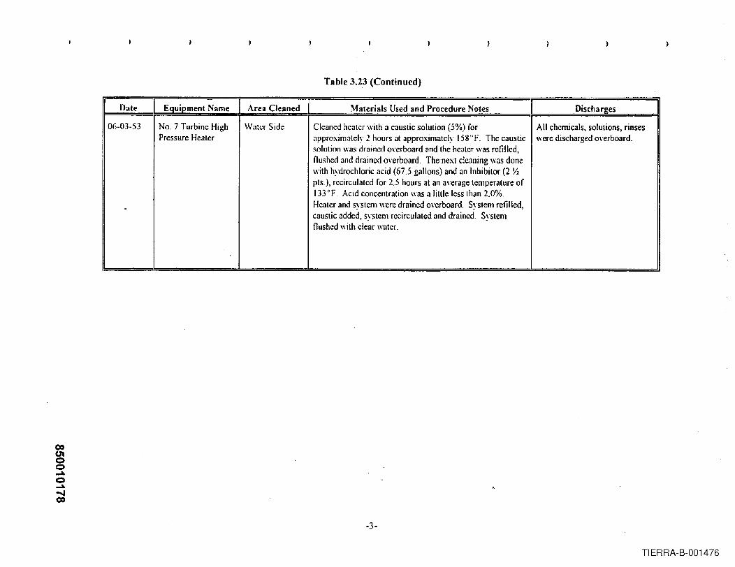
coU"Ioo...a.o...a.~CO
)
Table 3.23 (Continued)
[ Date I Equipme~t ~ame Area Cleaned C Materials Used and Procedure Notes I .Discha rges- . - - - ---
06-03-53 NO.7 Turbine High Water Side Cleaned heater with a caustic solution (5%) for All chemicals, solutions, rinsesPrcssure Heater approximately 2 hours at approximately 15goF. The caustic were discharged o\·erboard.
solution was drained overboard and the heater was refilled,flushed and drained Q\·erboard. The next cleaning was donewith hydrochloric acid (67.5 gallons) and an Inhibitor (2 YJpts.), recirculated for 2.5 hours at an average temperature of133OF. Acid concentration \\as a Iiltle less than 2.0%.Heater and system were drained o\·erboard. System refilled,caustic added, system recirculatcd and drained. System
I flushed with clear water.I
!
-3~
TIERRA-B-001476

Table 3.24
Typical HCIBoiler Chemical Cleaning
Drain Water Characteristics
AIl ..I)1.. Sp"" (.1unlllC D....ln Flnt IUIIU Oral" I""tH 1.5I
M~!ilu!"~t!'tgl:li! IIr\~n 5?00 ~,,,n 0.14 ~",II ICOf'fl".... nOnnm 0.311'1'111 1Nick=:! 210nnm 0.03ppm _JZil\~ 30 ~~" (HI I 1'1'1111
fl:lriuPh
'0,002 rrm Oll02 prm IOOlrrlll~-----.---10.17 nnlll
ou..·..('( IIIIKIII nlS
I._ .. .. . e
I I... _-
AL:idit"Alkalinity
A!!L!!1!lmm ". ~ 011'111 ··0.05I'nl1l ...
Ammnnia
t Amimnnv I 5.6rrm O.O~ ppm
I nl,,'r\'lIilll'~ I . 0.1 rrlll I '·0.001 ~nlll
I n\\n\I' I 6,21'1'111 0.23 n!'1ll
(':tkium. I 74 rpm I~ f1I1l11
r ('III",i<1< IChn>l1Iillm VI I 0.24pprn 1(\.h"lt 1.6 nom ' O.fJ06ppm
CoDFhh,.id<
M;'Ii!n~ium 42rrm 6.2 rrm
~lan2an""" 31prm o flfll1l
I ~l"!yhd",,um I 0.72 rrm I 0,03rrm
I ~ilral~ I 1:";Iril<
I ]'ll1l:<Oph.lfll\lS I II l'~llao;"..ium I .:}l'l'm I 3.2 Prrn
I ~iliCI)1l I 22rrlll .! 6.7 rrm
I S~lditlm I !(,°rrm I 35rrm
I S"It~I< I II "nlalli,,," I . 9 rem ~I IUI?rrl1l
ToeI V:m.1dium I fJ·.:\rnm I O.O! prill
R.·r: ,'.I'IH I'ISCES I),••• b.....
850010179
TIERRA-B-001477

Table 3.25
Raw MaterialsUnit No.1 (1947 - 1978)
I Mal. nab lln "nd O••• ri"tlo" EP" CERCLA Llst.dL.u...· S"b.t.ll.r
Furl.Bilumill~us Coal (wv. PrimM)' Source &. PA A!1cm.1Ie BoikrFud *Source-)
Na. '" Fue! Oil Boil".. Fuel ..Nahit:li Gas lloil(fand Comhust.en Turhine furl I I ~Comhust;on Air I R..~il~ and C~);'l1hu~tiflnTum;n~ I I , ~
I IF" ..I " .. ,Iiti ..... or Trr.l""-,,l, J IC~al Trol (22% Phosphoric Acid) M.y 11•• e Beenl1sed for Tr<olm""1 o!"Co.l Pi]es 10 Prevenl
.Fr~~zing
I plliier \VAil'r Trri.'u ......i ('SH"iui",als
I Sod.lIIll Sulfile B ..)il~r W.nt~r TTen"'l1~nt O:'\.'Y8.rn Sc-an\'cng,:r I .. ISo"ium Hydroxide NeUlralizing Agem I. .. I
I A---'lhydrouto Di~(.,dium Phrn:rh3'~ I B.,il".. Waler T...almenl. Ph""pl"1Ie Addil;on 1 .. II A,lhydmus Tri><XIium rhosphate Boil .... Wal .... Treatment. Phosphale Addilion .. II Ch",!"!'!:I('a'~IT,,...d 'For EOlllnli.,. .... (1('-anllll!l
I Sodium M.~.-Silicate Inili.1 Pre-()p.:raiion.1 Boiler CI,,,,"";c.l Cle.ninjl; IDow A • 120 Inhillil,..- Pre-O .... lion.1 Boil"r CIl",""ic,,1 CleMill [ron Oxide
·11-- lr~R~e~I1l~"::;~.:::.I------~---------~,---+--------I Thi,,,,,,,,, O"il.,. Chemic. I Cle.uing. ... C01'l"'r Rem,,..1
g.
I Cilric Acid BI,il ... Ch"lIlic.1 Cle'min~. Cun""r Rel1Klv,,1 :C==j11ydrochloric Acid Boil",/Cotld.'llSl.'r/Ue'I .... Ch"mic.1 Cle.nings. !r,", Removnl ..N£P·22 Inhi"il'" lnhihi .." lI""d Willi Hvdrodlloric Acid
Call'1;cS"dium lIydr"xid.:lCall.tic (N.OII) Ncutr.lize Acid;c Iligh Ch.-mical Cle"nill!l" for ..HI1;1",/Colldcn,.rIHe"l~
Amm.,nillln Hydroxide (A'I'" Ammonia) -I B"il ... Chemic.1 Cleaning Orllm.l. Clean;ngs I #<II
#<
1
I-,. -
Hydrnzine.1 100 Will waler ."I"tion llydrazine Wa.< lIsed As A p....... valiug Agent In Some 1 I ..B.,i] .... Chemic.1 Cle.ning Procedures I
Allhydrnu. T,i.odiulll Phosphale 1 Pre.Oper.lio","l D.'il .... Ch"mic.1 CleMillg'He.ler Cleaning I ..I P'htl ...nh~m(;Acid I noikr Chem,,,.l Cleaning I I ·
Allm,,'niul1l Carhon.'e noik,. Chemic.l Ck'\II;"~ j I ·S.~\.;1i~lm [lrom:ll~ n"II~r{~hcnticnl Ct~nn1ng
Pot:l.s,....hlln P~nnan~.j\nntr: F".'ll ... t,.,. 11".1<1"Chemic,,' Ck."injl; I I •I th.licAcid I F•• dwa!er lIe.I'" CII•.,,,;cal Cleaning I II Sodiunl C.rhon'le (Soda Ash) Neulr:llize Acidic Chemic.1 Cleanings for
J !Boil"r IColldell ....,./I1e.ders
I I I II W.tpr Sour,," I I i
Rivft"\\.'at~ C,'olin" 'md V.rillU. In-PI.nt ll"",
+==1N"w:lrk City W.l'" (pol,,"I,,) SanilAry Uses, B.,ikr M.keup Provided From Low Pressurenoiler i.} C"nd",," ..,le
I--
J
I I'".. n-(.'nll\:l"t (.' .... liIlP "-"h-r T ...."tlll.1I1 (1'''1111,,,\0 ~-I I
I Chlor;ne (drca 19:1:1) I 'Nt'rla(\'1I1~lo..1 Couling \\'ah.:r Cund..:n~r. ni~~iouiing C\lutru; I 1 "
850010180
TIERRA-B-001478

Table 3.26
Natural GasTypical Chemical Composition
Coml)otn·nt Mole Pcrccnhll'e
l"Jitrollcn 0.67%
Cad~ln D!oxid~ 0.71 %
~"i~thane 95.61 %
IEthane 2.37 %
I -
Pronane 0.36%
Iso-Butane 0.08%
N(l!11)~I-BHl:lI1<l 0.08%
III~o-Penlnne 002%
Nonnni Penlane 0.02 %
rl-k,;mes 0.06%
I Specific (iravitv 0.5848
SalHrnh.:d Bill PCI'Cllhie Foot (alI4,73 p~i ],014
I Drv Btu Per Cubic Font (0114.73 psi 1,032
850010181
TIERRA-B-001479

Table 3.27
Typical Unit No.1High Pressure Boiler Chemistry Limits
I Constituent I Limit or Range ]pH 10.5 - 10.8
Silica 2 - 5 ppm maximum
PO .. 25 - 50 ppm
Total Solids 100 - 150 ppm maximum
Specific Conductivity 350 - 550 umhoslcm
850010182
TIERRA-B-001480

coCJ'Ioo~o~ClOW
Table, 3.28Summary of Boiler Chemical Cleanings
(New Unit No. 1)
Date Equipment Name Area Cleaned ] Materials Used and Procedure Notes Discharges
11-15-47 No. I Boilcr Watcr Side of Thc boilcr was gh'en an alkaline boil out using the following The boiler was cooled andBoiler Tubes chemical combination: 2600 ppm trisodium phosphate, 125 drained "ia the discharge canal(Pre-Operational ppm caustic soda and 800 ppm sodium meta-silicate. Boiler to the Passaic River.Cleaning) was !ired for approximately 18 hours while blowing dO\\l1
through the "arious blowdo\\TI\'ah-es, Drum pressurevaried from 21 to 225 psi.
i.
Thc boiler was refilled with hot condensate, including thecconomizer and superheater, and then drained, leaving thesuperheater and economizer full.
The boiler was acid c1eancdwith Cl 3,8% hydrochloric acid The neutralized solution wassolution at IGO°F. Arter soaking for approximately 4 hours, drained via the discharge canalthe boiler was then drained to the acid cleaning tanks, where to the Passaic Ri"er.the spent solution was neutralized with caustic soda, beforedraining.
The boiler was then filled with city water and condensate at The city water rinse was drained I
150°F, and drained immediately (csti.matcd concentration of via the discharge canal to the0.15% Hel in the rinse water), Passaic River.
The neutralizing solution wasA neutrnlizing solution of city water and condensate with drained via the discharge canal0.25% NaOH and 0.5% Na,PO~ at IliO°F was pumped to to the Passaic Ri,·er.the boiler. Arter a I hour soak, lhe boiler was drained.
No record.The boiler was next filled with 190"F condensate anddrained to the acid cleaning tanks.
Chemicals Used:910 Ibs. trisodium phosphate280 Ibs. sodrum metasilieate44 Ibs. Oake caustic soda
,
5,000 gals, inhibited hydrochloric acid8 1/2 drums liquid caustic soda4 carboys phosphoric acid·
_._ ... ,. .._-_. _.". __ ..
TIERRA-B-001481

co(J'Ioo001.o.JoCO~
Table 3.28 (Continued)
II Date 1 Equipment Name 1 Area C"leJinerl I Materials Used and Procedure Notes Dischare:esI I I
02-01-49 Boiler No. I Water Side Chemicals Used': No record.S5 1/2 carboys of hydrochloric acid·55 1/2 quarts ofNEP-22 inhibitor9 drums of liquid causticNo other information available,
06-07·51 Boiler No.1 Water Side Chemicals used: No record.60 carboys of hydrochloric acid· -60 quarts ofNEP-22 inhibitor51 gals. (approx:)"of liquid causticNo other information available i
10-02-52 Boiler No. I Water Side Chemicals used: No record.1,000 gals. (approx.) of hydrochloric acid ("ia tank truck)23 gals. of NEP-22 inhibitor26 gals. of liquid causticNo other information a\'ailable
11-07-53 Boiler No. I Water Side Chemicals used: No record.1,400 gals. of hydrochloric acid ("ia tank truck)27 gals. (approx.) of NEP-22 inhibitor27 gals. (approx.) of liquid causticNo other information available,
-2-
TIERRA-B-001482
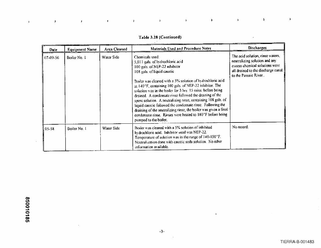
co01oo~o~COUI
Table 3.28 (Continued)
II n.....1110 I ~ _ •• : .....wTto6rt .. PUn.t'ftA ..A~reaCleaned Materia!s 1Isert and Procedure Notes I ()ischar~es ~van:: I L,.o'1UII'II.~IIL 1 .... 11.'--
07·09-56 Boiler No. I Water Side Chemicals used: The acid solution. rinse waters,5,011 gals. of hydrochloric acid neutralizing solution and any100 gals. of NEP-22 inhibitor excess chemical solutions were108 gals. of liquid caustic all drained to the discharge canal
to the Passaic River ..I
Boiler \\as cleaned with a 5% solution of hydrochloric acidI,
at 140°F, containing 100 gals. ofNEP-22 inhibitor. Thesolution was in the boiler for 3 hrs, 15 mins. before beingdrained. A condensate rinse followed the draining of thespent solution. A neutralizing rinse, cont<lining 108 gals. of
Iliquid caustic followed the condensate rinse. Following thedraining of the neutralizing rinse, the boiler was given a finalcondensate rinse. Rinses were hel1tedto 180°F before beingpumped to the boiler.
05·58 Boiler No. I Water Side Boiler \\I1S clel1nedwith a 5% solution of inhibited No record.hydrochloric acid. Inhibitor used \I"I1S NEP-22.Temperature of solution was in the range of 140-150°F.Neutralization done with caustic soda solution, No otherinformation a\'ailable.
-3-
TIERRA-B-001483

Table 3.28 (Continued)
Date Equipment Name Area Cleaned Materials Used and Procedure Notes . Dischar2es
10-03-65 Boiler No. I Water Side The boiler was cleaned in two stages. All drains from the boiler wenIFirst Stage: Copper remo\'al using ammonium bromate at to the south ash lake.(80°F. Solution contact lime was 6 hrs. Two rinses withcity \\ater at 1800 F completed this phase.Second Singe: Iron and copper remO\al using 7.5% Uninhibitcd hydrochloric acidhydrochloric acid, 3.0% thiourea and 03% A 120 inhibitor at was injected into the bromate150'T The solution contact time was 6 1m. The solution drain to reduce the bromate towas drained under a nitrogen blanket. The boiler was filled bromide.with condensate at 1500 F for the first rinse, and was drainedunder nitrogen The boiler was filled again \\ith condensatecontaining 0.5% citric acid and 100 ppm hydrazine for the~ rinse, and drained under nitrogen. The boiler wasliIh::dagain with 150°F condensate containing 100 ppmhydrazine, and 0.5% citric acid for the third rinse, anddrained under nitrogen. The boiler \\'as then filled with aneutralizing solulion containing 0.5% trisodium phosphateand 100 ppm hydrazine at 150OF. The boiler was fired to75 psig pressure for 6 hrs. The boiler was blO\m dO\m andfinally drained when chemistry requirements were met.
-4-
TIERRA-B-001484

Table 3:28 (Continued)
Ir Date I EQuipment Name I Area Cleaned Materia!s Use.-i an.-i Prnct"dur~ Notes Discha"l!~sI
10-03-65 Boiler No. 1 Water Side Chemicals used in First Stage:
(cont'd) 3,250 gals. aqua ammonia4,900 Ibs. ammonium carbonate2,700 Ibs. sodium bromate6,000 gals. 28% hydrochloric acid (used for neutralizingbromate).
Chemicals used in Second Stage:9,850 gals. 28% hydrochloric acid120 gals. A 120 inhibitor10, I00 Ibs. thiourea450 Ibs. hydrazine1,800 Ibs. trisodium phosphate700 Ibs. citric acid3,750 gals. sodium hydroxide7 gals. anti foam agent
Metal rcmo"cd:7,874 Ibs. iron (as Fe)2,693 Ibs. copper (as Cu)
-5-
TIERRA-B-001485

co0'1oo...a.o~CO00
Table 3.28 (Continued)
II Date 1 Equipment Name 1 Area C'leanl"li I Materials Used and Procedure Notes DischareesI ! I
12-08-73 Boiler No. I Water Side The boiler was cleaned with a 6% solution of hydrochloric The spent solution was drainedacid, containing 2.0% thiourea (for copper remO\'al), and to trucks for off site disposal.03% inhibitor. The boiler water side ,olumc was 40,000gallons. The solution temperature was 140-150'F, and All other boiler condensatecontact time was approximately 6.5 hrs. The boiler was solution were drained to thedrained under nitrogen to trucks for off sile disposal. The chcmical waste basin.boiler was rrlled with hot condensate and drained under
- nitrogen, to the chemical waste basin. The boiler wasrefilled again with hot condensate cont:!ining 0 1% citricacid and drained under nitrogen, to the chemic:!1waste basin.The boiler was refilled again with hot (180.1900 F)condensate containing 0.5% caustic for neutralization. Aftersoaking for approximately 2 hrs., the boiler was drained tothe chemical waste basin. The boiler was lilled again withhot (180°F) condensate and drained to the chemical wastebasin.
Metals remoycd (approx.):3,000 Ibs. iron (as Fe)
_ ..__ .- .500 Ibs. copper (as Cu).
,
* A carboy contains 13 II2 gallons.
-6-
TIERRA-B-001486

Table 3.29Summary of Condenser Chemical C1eanings
(New Unit No. t)
II Ijate I EqUIpment Name ! Area Cleaned I Materials Used and Procerfllrp Notes DischargesI
7/25/53 No. I Condenser Water Side Cleaned with il solution containing approximately 1,680 Spent solution drained to thegallons of hydrochloric acid and 132 quarts of NEP·22, discharge canal to the Passaicresulting in a 3.5% HCl solution. Spent solution drained. River. o·
FCondenser nushed with fresh water.
No. I COlldenser Water Side Cleaned with <lpproximately a 2.5% hydrochloric acid Spent solution drained to theinhibited with 128 quarts of NEP 22. Liquid caustic used discharge canal to the Passaicfor neutralization. Tcmpeniturc ",as IIO'F-115"F. Ri\'er.Circul<ltion method used. No other data a\·ailable.
4//16/55 No. I Condenser Water Side CIc<lned with 2.0% hydrochloric acid inhibited with NEP 22. Spent solution drained to theLiquid caustic used for neutralization. Temperature was discharge canal to the Passaic12WF. Circulation mcthod used. No other data available. River .
..
7/11/56 No. I Condenser Water Side Cleaning solution contained approximately 1,200 gallons of Spent solution drained to the20~ Baume hydrochloric acid and 124 quarts ofNEP-22, discharge canal to the Passaicresulting in a 2.5% Hel solution. Liquid caustic was used River.for neutralization. Temperature was 122 "F-125"F.Circulation method was used.
5/14/5R No. I Condenscr Water Side Clenning solution contained approximately 1,524 gallons of Spent solution drained to the i
20e. Bnume hydrochloric acid, inhibited with 55 gallons of discharge canal to the Passaic
NEP-22, resulting in a 3.2% HCI solution. Liquid caustic Riyer.\\as used for neutralization. Temperature was 104 "F-124 "F. Circulation method was used. No other dataa\'ailnble
()C)(hoo...o...()C)CD
TIERRA-B-001487

00U1oo.....o.....c.oo
Table 3.29 (Continued)
Date Equipment Name Area Cleaned Materials Used and Procedure Notes Discharl!es
12/21/58 No. I Condenser WlIter Side Cleaning solution contained npproximately 2,000 gallons of Spent solution drained to the200 Baume hydrochloric acid inhibited with 40 gallons of discharge canal to the PassaicNEP·22, resulting in a 4.2% Hel solution. Liquid caustic Ri\"er.WllS used for neutrali7.ation. Temperature was l28°F-136~F. Circulation method used. No other data available.
F No. I Condenser Water Side Cleaned with 3% inhibited hydrochloric llcid. Soak method No records.used No other data anilable.
6/21/6R No. ICondenser Water Side Condenser and two condensate coolers foam cleaned with Solution drained to the north ash4,400 gallons of 28% hydrochloric acid containing 32 lake. ,
gallons of A-120 inhibitor. Anti-foam (12 gallons) wasi
uscd to collapse the foam when it reached the outlet waterboxes. No other data a\"aiI3ble.IFlNO~ICondenser ~aler Side
---
FOilm cleaned wilh hydrochloric acid (10%). No other No records.information 3\':lilable.
-2-
TIERRA-B-001488

Table 3.30
Summary of Feedwater Heater Chemical Cleanings(New Unit No.1)
II Date 1 Equipment Name 1 Area Cleaned Materials Used and Procedure Notes Discharges
01-01-60 No. I Unit Hcaters Steam and Cleaned both st~am and water sidcs with 3% hydrochloric All solutions wcnt to dischargeI5 through 18 Watcr Sides acid and NEP-22. Neutralizcd with caustic. Rinscd with canal to the Passaic R.j,·cr.
condensate. Did thrce acid stages with same acid mix onfeedwatcr side only. Used a total of 100 gal. caustic and1,580 gal. acid.
II 07-26~69 No. I Unit Heaters Stcam and Cleancd with 8% solution of trisodium phosphate and No records.15 and 16 Water Sides 0.03% wctting agent, at 2400 F,
01-03·70 No. I Unit Heaters Water Side Clcaned with 5% caustic +2% potassium pemlanganatc at All solutions wcnt to discharge15 through Ig 200°F, followcd by a city water rinsc. Second stage was 7 canal to the Passaic Ri\"er.
1/2% hydrochloric acid +.2% A 120 inhibitor plus .25%oxalic acid, followed by a city water rinsc, followed by aflush until effiuent was same pH and conductivity as citywater, Third stage was 3% soda ash, which was drained hotto ash pit. Approximately 105 Ibs of iron, 7 Ibs ofmanganese, and .4 Ibs of copper were rcmo\"ed.
08-23-73 No. 1 Unit Heaters Steam and First stage: Cleaned with 3% caustic +2% potassium None. Drained to truck for off15 through 18 Water Sides permanganate for 6 hours at 180OF. Solution recirculated. site disposal.
Flushed "ith hot water. Initial portion wcnt to disposal Remainder of flush water totruck, remainder to waste basin. chemical waste basin for settling
and subsequent discharge fromstandpipe.
Flushed again with city waler. Flush watcr to chemical wastebasin.
Second stage: Cleaned with 15% hydrochloric acid +.3% None. Pumped to truck for offA 120 inhibitor for 6 hours at 165°F. Solution recirculatcd. site disposal.
Flushed with city water. Flush water to chemical wastebasin.
Third stage: A repeat of first stage. , None. Drained to truck for offsite disposal.
Flushes after third stage. Flush water to chemical wastebasin.
_ .... --_.
TIERRA-B-001489

Table 3.30 (Continued)
II Date I Equipment Name 1 Area C!ellnerf 1 Materials Used and Procedure Notes Dischar2esI I I
08·23-73 No. I Unit Heaters Steam and Fourth stage: A repeat of second stage plus acid fill and None. Pumped to truck for off(Continued) 15 through 1& Water Sides soak of steam side of heaters with same formulation. site disposal.
I
Heaters nushed on water ;md steam sides. Flush water to chemical wastebasin.
Fifth stage: Neutralization ,,"ith3% soda ash on water and Neutralization solution drainedstcam sides. Water sidc rccirculated. Stcam side just and nushed to chemical wastesoaked. basin.
Metals remo,"cd: 120 Ibs iron (Fe); 160 Ibs copper (Cu).
1
I
Water sidc "olurnc" 1,500 gallons
--Steam side \olurne .. 6,000 gallons
,
TIERRA-B-001490

Table 3.31
Combustion Turbine Units ~Operating Parameters
ComhustionTurhine IDI I
No, 10 Gas Turbine
No, II Gas Turbine
No, 12 Gas Turbine
I N<:\\ No, 9 Gas Turbine
... Retired......Replaced
coc.noo~o...:..CDW
Fuel UsedYearIn!talled
Voltlll\C
13,800
13,800
13,800
13,800
13,800
13,800
!963
Phasei i
Frcqucnc~' I Name PlateKW Rating
3
3
3
3
r60
6060
60 167,400
60 167,400
90,00060
No. or UnitsIn Plant
I 1 II~' _---I,
Il I II
I I I
Plant Capacit~·Maximum GeneratorName Plate Ratin2
30,000
53,133
167,400
167,400
~+I----~--~167,400
Of\ /VlI\7V,VVV
TIERRA-B-001491

Table 3.32
Low Sulfur Distillate Fuel OilTypical Characteristics
Perl' ..!!h bv Weill'ht:S!!lf!!r 0.05 to 1.0
HvdroQcn 11.8 to 13.9
ICarholl 86.\ to 88.2
Nitrll!'.<:n nil toO.1
Grlt,'i'v Vllluc~:
Del!rees API 28 t040 ..
Sp~cific Gravity 0.887 to 0.825
1\
D~n;cilv (po\lnd/g,allon) I 739106.87
III
Pour Pnilll, ell-g. F o to· 40
III Vi~clI~ih' Vnlues:~ C~1l1isloke~al 100°F --.
1.9 to 3.0
U SSF ;'11 122"f -.-~
..
II Water and sediment. % by vol OtoO.1
II He-~r.ing \'cllle BtH/pound gros'S IQ 1'1(\ ,,, 107':;""
API = American Pdrol~llm InstituteSSF = Seconds Sayhoh Fuml
Ref Sleam·lts Generation and Use, Bahcock & Wilcox. 40lh Edition, 1992,pa~e g. J 5, Tuhle 13
850010194
TIERRA-B-001492

Table 3.33
KeroseneTypical Characteristics
IPcrccnlagc! by \Vci,;bt: I I! !I Sullilr 10.01100.5
IHydrogen 13.31014.1
ICarhon 85.91086.7
Nilrogcn nil toO.1
Gravity V'llucs:
D.:grecs API 40 to 44
Specilic Graviry 0.825 100.806
Density (pounds/gallon) 6.87 t06.71
II Pour Point. dcg. F..... _- 1010-50
C. 1Visco.~itJValucs:
C.:nlislokes al lOooF I 1.4 to 2.2
I SSFnI 122°F ---~
I W:lter and~dimenl, % hy vol. --- .....
Healing value, BIll/pound gross 19,(\70 to 19,860
API = American Pelroleum InstituteSSF = Seconds Suyholt Furol
ReF: Sleam-lts General ion and Use, Bahcock & Wilcox, 40th Editions, 1992.page 8-15, Table 13
850010195
TIERRA-B-001493

Table 3.34
Low Sulfur Distillate Fuel OilMetallic Hazardous Substances
Typical Concentration (ppmw)
Suhdalnce An. Min. Mn.
Arsenic • NO·0.25
Beryllium ND - 0.05
Cadmiulll • ND - 005
Chloride .. ND - 30
Chrom iUIIl .. 005 .. 0.05 .. 0.06
Copper .. 0.2** 0.1" 0.5
Lead • 0.34 .. 0.25·· 0.5
Mercury • ND-O.I
Nickel .. 0.06 .. 005 .. 0.08
Seleniulll ND - 0.25
Sult\'r • 550 500 600
Zinc 0.15 0.06 0.26
,-ppmw = pans per million h}' weight
• Chemicals ciled in USEPA's leiter of April 30. 1996 to PSE&G
NO - 0.25. 0.1, or 30 '" Not Detected hy Anal)1ical Method 100.25,0.1 or 30 ppm Limit
Ref: EPRI PISCES Datahase
Nole: The EPRI PISCES Datahase conservatively reports "Non-Detect" analytical results as the detectionlevel of the analytical method used. Minimum :md Maximum data marked hy .. are, or in the case ofAverage include, NOll-Detect data reported at the detection level of the anal)1icalmdhod(s) used.
,-
850010196
TIERRA-B-001494

Table 3.35
KeroseneHazardous Substances
Typical Concentration
Ref 1 [ Ref2
Suhstllnce I (mg/L) (m2!k1l:)
3-Methvlcholanlhrene <0.\ ,<0.08
7,12 - --, 17.0
IIDiiiiethy 1hen.z( n)anthracene
I rAcenapht!1t~ne 40,51
25, 38 "''''
0.04< 2.0,73!D,~r,',."",,,,,,,< 0.50 , < 0.30 <0.01
< 0.75, < 0.09 <0.01
,..
II--_._., ~...Benz!)( ohi)nt'."'ilene 1 <2.0, <0.30 I[ II
II. ,£... ". -- ,- --
1Renzo(k)!lilor:mthene • < 0.50 , < 0.04 ! I:
~ Chrysene • 1 <2.0,<0.11 I U III Dihenz(n,h)anthral.:ene '" ] < 0.75 , <0.50 1 III flullranthene F < 4,0, to .I 0.09 III fluorene '" < 2.0.36 J III lnueno( I ,2,3-c,d)pyrene I < 2.0, <0.30 JII Naphlhalene '" J 1,286 , 2,000 JII Phen:mthrene J 1.9,493 J U
II pyrene '" J <20 20 J 016
<075 <020[. II
mg = milligramskg = kilogramsL= LiterRef I - Gnodm:m & Harbison 1980Ref2 . Guerin, 1978
• Chemicals cited in USEPA 's leller of April 30, 1996 to PSE&G·.Range and mean values reported
U =Umklel.:led
,- 850010197
TIERRA-B-001495

Table 3.36
.... Raw MaterialsCombustion Turbines
1963· Present
Chcmicab Used for Cooling System (UnitNo. II and New Unit No.9 Only
I Ethylene GlycolCOITosion Inhihitor (unspecified)
*
Comhustion Air Comhustion Turbines
~CERCLA Listed
Letter Suhstllmce
I I
I
*I * --
-- ,,_.
Fuel Additives or Treatments
Comhustion Turhine Fuel
Material Use lInd Descrilltion...
Natura! GnsNo, 2 Distillate Oil Comhustion Turhine Fuel
Kerosene Comhustion Turhine Fuel
COlllustion Tm-him: Fuel Additives *
Comustion Tllrhine Fuel Additivcs
Pcnctone 19(1)] II-----~
I,:Cb.cmicaIsUsed Fo.r Equipment Clenning~Not Annlicahle
Water SourcesNewark City Water (potahk) Makeup to Closed Loop Cooling
Non-Contact Cooling Wnter TreatmentChemicals
I Nol Applicahle~:.w;;u.:JL.:.!.!.:;l!.~ ,JL.... J.__ •..l....-_--_.1
(I) Conluins hexylene glycol (13,0%), whch is not on lhe CERCLA huzardo\ls S\lt>stances list Other constituents ofPenetone-19 are not identified_
850010198
TIERRA-B-001496

1 1 "} 1 ;
TABLE 3.37ESSEX GENERATING STATION STORAGE & PROCESS EQUIPMENT
1
II 1 Carttairter'TVf//!
Cun-ertt StMU$Lccatiotl
1,673 gal
Concr.'. Dike
Conere,. Dik.
Productn'ne
Product(Juafiiitv
Corttairtment/Diverslort~ T...",
Eanh.n Dike
No.2 Tank Steel Tank (ES)U •• Changed - 1990
No. I Tank Sleel Tank (ES) 5.E. Comer Yard No.6 Fuel Oil 20,000 hhls
SI.el Dike
No.2 Tank 51eel Tank (ES)
Steel Housing (PJ11 No. II 5talio" Power Transf.
Sl.el Housing (P)II No.5 $'3'",n Power T.-.n,f.
II No.6 Slation Power Transf.
IIHO'..... H •• li~g BQi!e. Tank
Ga5Q~ine Tank
II Di.s,,1 Tank (2)
Stee I Housing (Pi
5.1'.. Comer Yard
S. E. Comer Vard
N. Boiler House
TransHOil
Tr8nsH Oil
No.6 Fuel Oil 100.000 bbl.
OM Waler 100.000 bbls
E. ~-,ac;rHouse
1,955 gal
I 1,955 gal
5.1'.. No. I Dri". House
&,000 gal
G"oline
Sleel Dike
Concr.te Dike
Co", .. le Oil.'."No.2 Fu"l OilSleel Tank (ES)
Fibergla •• Tank (UST)
W. Side Switoh House
5.1'.. No. I Drh. Hoose
None1,000 gal
None3,000 gal1,000 galSleel Tank (UST) Di ... IO;1
II Hazardous Wasle Drum StOr8ge Ar.a
II C-13H Ruclor
I St.e1 DNms!(ES)
S•• e1 Housing (P)
I s. Unil No. 12
13SKV Yard
I Wast. Oil J55 gal Drums = 15
_ Drum.
13.700 gal
Hous<:k"eping (CrushedStone)
Remov.d From S"rvic.
Dieleclric Fluid (Transil Oil) 5.725 gal
H-1308 R"actor S,.eI Housing (P)Hous<:keeping
W·1323 Rea.:tor 51eel Housing (P)R"moved From S.rvic"
138KV Vard Dielectric Fluid 3,725 gal
Housekeeping
No. 132-1Pha .. I
S,.el Housing (P)
II No. 132-1S.eel Housing (P)
138KV Yud
138KV Vard
138KV Yard
TransilOil 3,725 gal
Hou.eke.ping
Housekeeping
, Replaced
Replaced
Steel Housing (Pl
II ::~:2-1Phas.3
It N.o .. 13.2-1. Pha.e I
....:...:.;=..:....--------.+-----~-J "'KV Y••Ste.1 Housing (P) 13RKV Yard
Transil Oil 13,700 gll
TransilOil
I Transil Oil
I Diel.ctric Fluid
\13.700 lIal
I 4.595 gal
IT.nk Cod,,, P : Pr"" ... ; ES : Exl.rior Storage; IS = Interior Siorage; U5T . Underground Slorage Tank
-I Hou .. keel'ingReplaced
J H()u.ekeepinll
850010199 IOFt6
TIERRA-B-001497

) ")-, ,
TABLE 3.37ESSEX GENERATING STATION STORAGE & PROCESS EQUIPMENT
r Designation 1 COnlaind I Location I Product I f'roduct r CoJllainmrntIDi,·trsioll Cu"rnt SlQ/usII
TVl't Tv"t '}:u:r:tltv TI'"e
fIIo.132·1 Sleel Housing (P) I311KV V.rd Diele~lric Fluid 4,595 g.1 HOluekeeping
Ph.s.: 2
No. 132·1 Sleel Housing (P) 138KV V.rd Dkk~lric Fluid 4,595 gal Housekeeping
Phase 3IIII
....::O~iIO:.:.sl;;;.;al.:..;.ic...:.T,;;,;..n:;,;.k ......:.;.;;;.;..:..:;;;;;:..~---l_..::.:.;..;...:.;;;.:;...:..:.=---+-...::.:..;.=.;:...:..:,;;,;.::...-----i--=:.;.:..:.;~:;;..----·+....::;=:;=;;;.;;;;;;,;;;.;.;;;..;...;;~--4TC-----
~.~n Un"~ IIi Sleei Tank (P) I
Oil P"l.inlp House
t
D;~le~'ri~ Fluid 20.000 i/.I Devonion/Concrele Dik.
Sled Housing (P) Pump House Dielectric Fluid I fIIIA o.versionlCnncre!e Dike
'1 SI.el Tank (P) I Nexl 10 Pump H()u~ I Did.ctric Fluid II 10,000 g.' Covered Con<:rele
1 Sleel Tank (P) 1 Oil Pump House I Ditkctric FluidII
12,000 g.1 Devenion/Concrele Dike
1i
(6,000 galleal:
51eel Housing (P) S. No.8 Unil TransilOil 3.800 gal Concrelo Dike
] 5'eel Housing (P) .I N. No.9 Unil I Trans;lOil 3.560 gal Concrele Dike
I
Sleel T.nk (P) Nn.9 Unil Generalor UiDe Oil 3,300 galI
51«1 Tank (ES) N. No.9 Unit DOT-2M 1,000 gal Concrele D;ke I Removed From ServIce
I
Old fila. 9 Unil Gen. LUDeOil Reservoir
Old No.9 UnilII Chemical Additive Tank 1 1\ :,::::N~::~:, ON;' T", Steel Tank (USn N.W. Comer fIIo. 9 Unit No.2 Fuel Oil 275 g.1 Removed From Service
] ~.
, I
Sleel Tank (1)) N. Side of Unit No. 9 183 gal j Hoosekeeping Removed From Service
(91 Ital/ea)
II Drum Storage Ar.a J St •• 1 DNms (ES)~
W. Unil No. 10 I V.ar;ous Orums~
55 gal Drums (47) i Concrete Dtk.e I IUnit No. 10 Fuel oil Reclaim Sumps 51•• 1Tank (P) 5. Unit No. 10 Kern .. ..: 100 gal (55gallea) Con~re,e Vauii
(2)
No. 10 Unit Fuel Oil Drain Tank (4) Steel Tank (UST) fII. & S. Comer No. 10 No.2 Fuel Oil 250 gallea 1,000 gal Removed From Service
Unil
Tank No.3 Sleel T.nk Installed
JS.E. Corner Yard
IKerosetK
~
5,040,000 ItalEo""" 0;'"'''' C1"~'1
With Leak Deteelion(ES)
Liner
II No. '20-1 Transformer J,
Sled Housing (p) I 230KV Vard I Dick,trio: Fluid (Transil Oil) I 2' ,000 @ai I Hou30:L.~~ping
20fl6
'T.nk Codes: P = 1>ro.:e.. ; ES = Exterior Storag.~ IS = lntaior Slorage~ UST • Underground Storage Tank850010200
TIERRA-B-001498

) -. ) ") ) ")
TABLE 3.37ESSEX GENERATING STATION STORAGE & PROCESS EQUIPMENT
II Designation 1 Contain,,} 1 fAlcation 1 f'roduct I f'roducl I Canuzin""1Itl Di,',rIianI
Current Sialus
T'i'fJ~ r"I"Jt Ouafltitv n'pe
11/'01", 220-2 T"n.f.,rm.r 5 ... 1 Housing (P) r 230KV Yard Di.k"I';" Fluid (Tron.i1 Oil) 18.000 gat (17,010 g.I?) Housekeeping
II No, 26-2,0. Transformer j 5••• 1 Housing (P) I I3KV Yard I Oiel«lri" Fluid (Tronsil Oil) 7,380 gal Housd,.eping
~ :: :::: T,,",f,~,I Sl;::~!Housing (P) I !.3KV y,.!"~ I Di<leClri. Fluid (Transil Oil) I 7 ,3M ~al Ilou.d:«ping !I
1
- ----
Sled Housing (P) I3KV Yard Dieleclnc Fluid (Transi! Oir) 2.145 gal Housekeeping
II ~lasd
1
~ --
51.. 1 Huusing (1') I3KV Yard Diel ... ri. Fluid (Transil Oil) 2,145 gal HousekeepingNu.26-IAPh:ll ......,
II ~~-.':6~ I A S.eel Huusing (P)1
I3KV Yard Diek"lnc Fluid (Transil Oil) 2,145 gal Hou,.keeping
II ::'.':6'.1 B 1 S•• el Housing (P)1
I3KV Yard Di<l.",nc Fluid (Transil Oil) I 2.145 gal Housekeeping
PhA"'~ 3-
II N", 26-18 Sleel H"",ing (I') 1IJKV Yard Dieleclnc Fluid (Transi\ Oil)
12,145 gal I Hou..:keeping
II ~~~':6~IB
----,---
51.. 1 Housing (P) 1 13KV Yard DielOClnc Fluid (Tnns;1 Oil) [2,145 gal I Housekeeping
P1use t
II Transil Oil Tants (5) 1 S'~~I Tank (ES)
"'
13KV Yard ] TransilOil 1 30,675 gal I HouKkeeping Removed From Service
No. 132"3 Tap Changer Sleel HOlls;ng (P) 13KV Yard Transit Oil 4,350 gal Housekeeping Remnv.::d From ServiceII
No, 132-J St .. 1 Housing (I') 13KV Yard Diel.elne Fluid (Transil Oil) 7,430 gal HOUK keep ing
Phase 3
II Nt>. 132-3 -r
~~Sle.1 Huusing (I') I3KV Yard Diele"lric Fluid (Transil Oil) j 7,430 gal I Housekeeping ]
Phase 2
No. 132-3 Sleel Housing (P) I3KV Yard Di.leclric Fluid (Transil Oil) 7,4JO gal HOOl"keeping
PhaM I
Nu. 132-2 Trap Changer SI"el Housing (P) 13KV Yard Dielecln~ Fluid (Transif Ojl) 3.960 gal Houseke~ping
I No. 1J2-2 SlOel Housing (P) IJKV Yard Dielectric Fluid (Transil Oil) J7,430 gal I Housekeeping
""as. 2
3 OF16
'Tank Cude., P = Pro« .. ; ES = EXlerior Slorage; IS = [nle ..ior Stor.ge; UST - Underground Slor.ge Tank 850010201TIERRA-B-001499 .

TABLE 3.37ESSEX GENERATING STATION STORAGE & PROCESS EQUIPMENT
r Designation
Ii N<J. 132-2
1 ConltJinerTl'~(! I 13KV y~'.'
ProductT,'ne
I Product ContainmentlOi"trslonTI'f/e
CurreN Stalus
Sttd Housing (P)
jl3KV Yard
Diek"tri" Fluid (Transil Oil)
Diek"tri" Fluid (Transil Oil)~
I 7,430 gal I HO<Jsekteping ~-'No. 132-4 Transfonner
Unit No. 10 aeneralor Lube OilR~~~rvoil' (4)
Sttd Housing (P)
Stttl Tank (P)
N. Unit No. 10
Unit N". 10 Generalor
Did«I";" Fluid
Lube Oil
No.2 Futl OilN. & S. Coma No. IIUnil
9,500 gal
400 gal (100 gal/ea)
Hm.... kteping
Building
Removed From Strvice
Sted Housing (P)
Steel Tank (E.S)
51eel Housing (P)
Sletl Tank (USn
Steel Housing (P)
Sttel Tank (P)
1 N. No~ II Unit
Unit No. II
Dielectric Fluid
Kerotene
I [1,440 gal
275 gall.. f2.200 gal)
I 3,900 gal
950 gal(475 gallea)
Housekeeping
Concrete Vault Removed From ServiceIN."M N. "
1 Sleel Tank (P) Unit No. II Generator 1 Lube Oil ]1,000 gal
(250 ga1lO8)1 Building
Chemical Addiliv. Tank S. Unit Nos. 10 & II DGT-2M 2,500 gal ConereI. Pad & Dik.
No~ 12 Main Transformer
No. 12 Unit Fuel Oil DrainTank (8)
1 51eel Tank
N. No. 12 Unil TransilOil
N, & S. Comer No. 12 ., No.2 Fuel OilUnit
14,130 gal
275 gal/ea (2,200 gal)
Housekeeping Removed From Service I
Lube Oil Storage Steel Drums W. 1'10.12 Unit Multigear B, Gulf"resl 44,Turbo Oil, 2380, Fryquc1 220,Harmony 4JAW, Alurl>rio71
55 gal drums
No. 12 Main Transforn.er
I
Unit No. 12 Fuel Oil Reclaim Tank(2)
Unil No. 12 Generator Lube OilReservoir (4)
Steel Housing (P)
St~tl Tant (I')
Stetl Tant (P)
N. Unit No, 12
S. Unil No. 12
Unit No. 12 Gen~ralor
Oidcctrk Fluid
Lube Oil
'Tank Code" P = Pro.:e.. ; £S = Exterior Storage; [S = Inlorior Storago!: UST . Undttground Storage Tank
8,900 gal Housekeeping
Building
850010202
Removtd From Sorvicc
40Fl6
TIERRA-B-001500

TA~LE3.37ESSEX GENERATlNG STA nON STORAGE & PROCESS EQUIPMENT
II l)esi/tnali,m
I::':'::~,~:::r:~.II~:~~:ir9G.n..-alor.Lube Oil
26KV Tie BusO-U R.a~lors (3\
1 ~:CI
II:'~~A""
Lub. Oil
1~;::':':':''::':'----------·-I----------+----------I_D_i._I_h_'ln_'"_F1_U_id _
Oielemie Fluid
1 C01Uainltri_____________ 1-' ...;.T:.;;\"f:;;t -ii- f. .....::;;::.~ .I_-----':..::.::.:::.::.::..-- __Il----..:.:~--- __f--------=
1151«! ra"k (I'-~l
SI.e1 Housing (I')
1 5te.1 Tan"- (P)
Group ·u· OCB (3)
51•• 1 Housing (I')
51.. 1 Housing (P)
Ulcalion
S. Unit No. 12
Unit No.9
Unit No.9 G.n.ralor
26KVS",il<hvard
26KV 5wilchyard
ProdUCIO/lQnliJv
ConlainmltnllDi.rrswnTvpr
If Concrete Pad & Di ....
Concrele Padday pil with Sump
Diversionory ColleclionSv5lem
Currtlll StaJus
C·289, N-248 OCB (2) Sleel Housing (I') 26KV Swilchyard Dielectric Fluid 530 gal1165 "aile.)
Housekeeping
Plan"- Rd Reactors!'base's 1-3(3)
II V-48 PI.n'" Rd OCBm
II No.9 G.""ralor Transrormer
Sleel Housing (P)
Steel Housing (P) 375 gal(125 0.lIe3)
j 330 gal(IIOga11<3)
26KV Swilchyard
26KV Swilchyard
1,071 gal(357 val'.a)
Housekeeping
I Sltel Housin: (P)
Sleel Housing (P) 26KV Swilchyard
Di.leclric Fluid
Housekeeping
Housekeep;ng
L·12 Ironbound OCB (3)Transformer
Sleel Housing (P) 26KV S... ilchyard
Di.lwric Fluid
240 ..al
Housekeeping
26-2 Trans. Group ·U· OCB (3) Ste~1 Housing (P) 26KV Swi.chy~rd
D;electric Fluid 1,071 gal(357 2.1Iea)
Housekeeping
Group 'U' Secondary PT (3) Sl~el Housin, (P) 26KV S.....ilchyard
Dielectric Fluid 375 gal(\ 25 0.11•• )
Hou .. k~eping
No. II Slal;on Power INo .. · No. 13)
26KV Transformer Bus OCB (3) 318 galtJ06 Dal/e.l
Sleel Housin2 (I')
Sleel Housing (P)
26KV Switchvard
26KV Switchy.rd
Dieleclric Fluid 315 gal(l05 ..a110a)
Dieleclric AuM! 15 gal(5 ... 1/•• )
Dieleclric. Fluid
Did.elri. Fluid
'Tank Codes: P = Process; ES = Exterior 5.<>rag<: IS = Interior Stor.ge: U5T . Underground Storage Tank
Housekeeping
850010203 501'16
TIERRA-B-001501

TABLE 3.37ESSEX GENERATING STATION STORAGE & PROCESS EQUIPMENT
I llesigllalioll CM/oiller' I l..ocoli,m /'I"m/ucl Product COII/ojllmelllllJil'efS iOll I Currelll Sl4tur II T\''''e T\'"r Oualltitv Tw'ei
G,ou(> O~U Trans Bus RO•• lors (3) Sto<l Housing (1') 26KV Swit.hyard Di.lwri. Fluid 1,071181 Housd:'<el'ing057 ~811.. )
26KV 132·4 Primary PT (3) St.:ol Housing (I') 26KV SW;I"hyard Diok.tri. Fluid 12 gal Hous<l:.<eping(4 ~al/ .. )
26KV Grouo '0· OCB St .. 1 Housin .. (I') 26KV S"'j,,h\'.rd Di<lwrie Fluid 105 ~.1I•• II Hou .. keeoin~
51.:.' Housin" (I')
IIHou,ekeenin!"0327 Roa"tor & 1556 26KV S""iloh"",d Did«I";" Fluid 265 0.11•• !I
II H~1l6 Plank Rd Roaclor (3) I I I II
St.:el Housing (1') 26KV SW;lchyo,d Dioleelrie Fluid 720 gll I HousekeepingI(240 !"olloa)
I H-86 OCB's (3) Steel Housing (1') 26KV Swilchylrd Diel ... ,.;. Fluid 375 gal I Housekeeping(125 Pille a)
It r'Lts..1.'O ........I ....~ I S!'!~!Hnu!~n"(p .. I 26KV Sw~t~hv~"d I Oiel~.:lnc Fluid I 265 !"al I Housok"l'in~
I ::::: ;:~~:~nd Rmton (3)
--
SI.:eI Hnosing (I') 26KV Sw;tohyard Di"omie Fluid 971 gal Housekeeping05701l/ea)
II 0-368 OCB's (3) I Sleel Housing (1') I 26KV Swilchylrd I Di .... trie Fluid J 375 gal I Housekeeping(125 "all •• )
I 1-87 Pllnk Rd R.lclor (3) Sleel Housing (1') 26KV SwilehYlrd Di.l .. lric Fluid 1,011 gll I Housekeeping(351 "allea)
I (-87 OCB (3) Stod Housing (P) 26KV Switch yard Dielectric Fluid 375 gal I Housekeeping(125 oalloal
I 132-4 26KV Group '0' OCR (3) Steel Housing (P) 26KV S",·it.hyard Didoclne Fluid 315 gal I Hou..,keeping
J(105 "aIle.)
I No, 12 SIOlion P..,wer 51.:<1 Housin!" (P) 26KV Swil.h\'.,d Diel .. tric Fluid 240 val 1 Housekeeping~
111-85 Harrison OCB (3) (Nn .. ' 4-25) I Slc,d Housing (1') I 26KV Swilchyard Dielccllic Fluid 375 g,l
.1HouutcepinJ
J(125 ",Ilea)
I_ ..
j JX-102 A&.B OCB(J) SI .. I Housing (P) 26KV Swilohy.rd Diel«lric Fluid 411 gal Hoenekeeping
(137 ltall.11
I T-358 CI.)' SI .. OI OCB (3) (Now 1'.1- Sled Housing (1') 26KV Swilchyard Dielectric Fluid 318 galJ
Hous<kc<ping j21\ fI 06 oal/ •• ,
60Fl6
'Tank Cod.s: P = Process; ES = £"I<rio' Slor.g,,; IS = Inl<';I>' Stl>rog"; UST - Underground Storlg. Tank 850010204TIERRA-B-001502

TABLE 3.37ESSEX GENERATING STATION" STORAGE & PROCESS EQUIPMENT
Perigtlll/lo" Cotl/ai"e'; Loca/io" /'rodUCI ('roduCI Con/aj"metl/IOi"ers/o" Curre'" SIll/us
Tme TWIt Ollarl/m' T\'oe
Z·52 Hurison OCB(3) St.,el Housing (P) 26KV Swi(,:hyard Dide~tri~ Fluid 411 gol Housekeeping(\37 ~allea)
I~KV Group M OCB(3)J
Steel Hoosing (P) I 26KV Swi("hrard Dide.:tric Fluid 390 golI
Housek«p;ng1130 ~allen)
I 132-1 Tronsformer Group Mace Steel Housing (1') 26KV S....ilch)'ard j Dieket";~ Fluid I 390 gll Housekeeping
(31 (130 gollea)
132-1 Transformer 26KV PTS (3) Sleel Housing (P) 26KV S....itohyard Dide':l";c Fluid 45 gol HousekC<(Iing115 ,,"lIe.)
26KV Transformer Bus I-M OCB Sled Hausin" (PI 26KV Switch"ard Dielectric Fluid 125 "ollea Hoosekeeninl!
Transformer Bus I·M Synch Sleel Housing (1') 26KV S,I..itchy*rd DieleelT;c Fluid 5 gol Housekeeping
Transformer
1'-94 Hamson OCD (3) Steel Housing (P) 26KV Swit.hyord Dielocuie Fluid 375 gol Hou""keoping
I J-556 Path OCB (3) (Now G-1(3)
(125I1,l/e*t
Sleel Housing (1') 26KV Switchyord Dicle~lri.: Fluid 31S gll HousekeepingI
((06 0311ea)I
5-357 A&B Re"l<lr 51«\ HOl.. i"" (PI 26KV S" ..it~h,·ard Di.l.w;.: Fluid 265 ..01 Housek«"in ..
H-346 Clay SI OCB(3) Steel Housing (P) 26KV SwitehYlrd Dicleclric Fluid 318 gll Housekeeping
I(l06 "alleal
26KV Tie Bus Group -." OCB(3) Steel Housing (I') 26KV S"'ilchyard 1 Did«lrie Fluid I 390 gll Housekeeping
I(130 J!all~a)
132-1 Transformer 26KV Group. Sled Housing (P) 26KV Swilchyard Dieleclric Fluid 390 gal Housekeep; ng
OCRI]1 / 130 gall~.)
I 26KV N~utrol R~$;sIOr Shunl OCB ] Sle ..1 Hous;"!! (f) I 26KV Swilchllud~
Diele~lric Fluid I 100 Fal (-rrrex) t Houselc~eping
I 26-1 Transform~r 26KV OCB(3)
~51....1 Housine (1') I
26KV Swil~hyard
-\Dielectric Fluid
I315 gll
~
Housekeeping(105 ,ol/co)
!26KV Tie Bus Group I-M Rcaelon
~Sleel Houling (1') I 26KV Switchyord
-IDicle.:tric Fluid
I3,300 gal
~
Housekeeping
. (3) (1,100 !!"1/~0)
1126.1 Pot Tran.form" (3) J Sleel Hou,ing (1') I 16KV Swilchysrd J Dielectric Fluid I 45 gal.I
Housekccpine Removed From Service(15 g.l/e3)
,
850010205 701'16
IT•nk Cod.:s: P = Pro;:ess; ES = E'lerior St,,,ag¢; IS = Inlerior Slor.g~; UST • Underground Slorage T.nk
TIERRA-B-001503

TABLE 3.37ESSEX GENERATING STATION STORAGE & PROCESS EQUIPMENT
1[1DtsillnOlion 1 Con/aintr I V:J(:a/iolt
1Produc/ I l'roducl Con/a;nl/lt It/!l>i"trsion currtnJ~~
Tr?, Tv", OUQIf/ifI' Tl'pt
Polo,"li.1 Tran.f"nn~r 51.. / Hou.inJ! (P) 132KV 5witeh"ard D;~l<eln.; Fluid 15 oal (al'l'r<lx) Hous<k.. "inJ!
C·IH5 & 132·4 B&R OCB (3) SI~.I Housing (P) 132KV S"'itchyanJ Did."ne Fluid 3,510g.' Hou .. k~~ping
I 210· I.138KV Br.ak~r (3) I(1./70 g.ll.o)
51.01Housing (P) 132KV SWileh)'ord Oi.l<ctne Fluid 2,550 g.1 Hous.k~.ping(N50~all•• )
\I 132·1 Transfom,.r 132KV OCB(3) I SI~oIHousing (P) I InKV Sw;tehyard I D;.kelne Fluid I 3,510 gal1
Hous.ke~ping
I ](I. 170 ~.11•• )
132KV Main Bus S.e 3·4 (3) SI.. 1 Housing (P) 132KV Swil.;hyard Di.le.;tne Fluid 2.550 gal Hou .. ke·ring(850 oal/.a)
I H-1308 & No II Main Transform.r 51.01 Housing (P) 132KV Switch)'ard j Di.l.elne Ruid 2,475 gal Hou$Ok•• ping
l38KV B.. aku (3) (825 l!al/.a)
11132.2 Tran.form.r 132KV DCB (3) I St.oI Housing (P) I I32KV 5"'itchyard I Dielectric Fluid j 2,550 gal1
Hou.. keering I
1
(N50~al/<l) I
132KV See 2, Bus T;~ OCB (3) Sled Housing (P) InKV S"'ilehyard Diel.Clrie Fluid 2.550 gal Ho.... k··r;og(850 "all'O)
11220-2, 138 KV OCB (3) SI~el Housing (P) I32KV Swilehyard
JDi~leclric Fluid 3.510 gal
~Houseke.ring
(1,170 J!all~a)
132·3, 132KV OCB(3) St•• 1 Housing (P) 132KV Swilehyard Di.I.elri. Fluid 3,420 gal Hou .. k.~J1ingII,! 40 "all~a)
IJ2KV "lain Bus Se. 1-30OCB (3) St.d Housing (P) 132KV S,,·it.hyard Di.leetric Fluid 2,550 gal Hous.k··ring(850 oall.a)
II No. g Li1!hlingTrnnsform.r J St.<I Housing (P) -I 13KV S"'itch"ard .1 Diele<tric Fluid ~ 20 ga' (approx) ~Houstke-~ping
II No. 7 Lighting Transform<r ~ SI.~I Housing (P) ~IJKV Sw;I.hvard
~Diel.<lnc Fluid
·120 gal (ap!,I'OX)
~Hou~k.~pinl!
II OCR's (3) St.e1 Housing (P)
.113KV Swil<hyard
.1Oi.l.otne Fluid
~
174 gal
~HouKk··ri",
(58 gal/.a)
0319 Cily DIXk IJKV OCD (3) Steel Housing (P) I3KV Swil"hyard Oi~leetri. Fluid 174 gal Hou~kecring(511".1: •• )
VJ37 Cilv Dod. 13KV OCB (3) St.. 1Housing (P) I3KV Swit.:hy"rd Di.l."'rie Fluid 174 gal Housek.. pingIN",,· y.j)7\ 158 •• 1/."'
850010206 801'16
'Tank Cod.s: P ~ PrIX."; ES R EXlorior Slorag.; IS = Interi"r Storage; liST - Underground Slorag. Tank
TIERRA-B-001504

TABLE 3.37ESSEX GENERATING STATION STORAGE & PROCESSEQUlPMENT
II /)esigno/il)r/ Con/oinel Loca/wn Product /'roi/ud II Containment/Oil'ersion l~Current Slatus
T\"iiE T\'~e Ollanlin' Trpt Iii
H320 OCB (3) SI~.1 Housing (P) I3KV S,,'i!,;hyard Oi,;le,;t,;,; Fluid 174 gal Hous.:keeping1511..allea)
L324 13KV OCB (3) S!.~I Housing (P) UKV Swit,;hyard Djd4!~,ri, Fluid 174 gal Hoo...k«"ing(511l'al/,;a)
1132-3 Transformer 13KV Group ·0· SI~e1Housing (P) 13KV Swil,;hyard Di<l"t,;,; Fluid 390 gal I
Housek«,,;ng
~ IOCB (]) (130 v.I/.:.)
I 26-\ Transformer I3KV Group ·0' SI«\ Housing (P) I3KV Swil,;hyard Oid«tr;,; Fluid 390 gal I Housek~.ping
~ IOCB 131 (DO ..alha)
I 13KV N,;ulral Ground Transfo"""r SI•• I Housing (P) I3KV Swilchyard Di~I~..:trk Fluid 390 gal
IHou.ekeeping
~ II3KV Grooo '0' OCB (31 (I 30 ~.I/<a)
I3KV Ti. Bus Grou" ·0· oCB (3) SI.e1 Housing (P) 1JKV Switohyard Di.kClric Fluid 345 gal Hou~k~.pjng(115 ~all.a)
I3KV Ti. Bus Group ·U· OCB (3) SI~e1Housing (Pl I3KV Swilohyard Did~clric Fluid 345 gal Housekeeping(I 15 23l1ea)
II I3KV Bus Group "U" vr (3) I St.e1 Housing (P) I I3KV Swil,;hy.rd I Did,;,;!';,; Fluid I 45 gal I Housekeeping J I(15 gal/ea)
I13KV Neulral Ground Tran. 13KV Ste~1Housing (P) I3KV Sw;(chy.rd Did.cl';c Fluid ~345 gal IHousek•• ping
~Grouo AU· OCB (3\ 1\ 15 ~al/ea)
1
I
1JKV N~lI'ral Ground Transformer 5,«1 HOllsin!!(P) 13KV S,,'il~hva,d Dioleolric Fluid 1.013 j!.1 I Hous.k •• pio/! -1 I1126-1 Transform« PTS (3) I SI•• 1 Housing (P) I I3KV Swil,;hyard I Di.I",';, Fluid I 57 gal
JHous~k.eping J I(19 BaIJ~a)
Group O-U PT's (3) SI•• I Hou.ing (P) I3KV Swil,;hya,d Oieleotri,; Fluid 30 gal Hou.. k~.ping(10 ... 1/•• )
26-1 Transform.r I3KV Group ·U· S.eel Housing (P) 13KV S,,'il~hyard Di.I~ct';c Fluid 390 g.1 Housek~eping
OCBm 130 ~.I/ •• )
132-3 Transfurmer I3KV Group ·U· SI~~IHousing (P) 13KV Switohy.rd Di.I"lr;' Fluid 342 gal Ho.... k•• ping
oca (3)1114 pall•• )
No.5 Slat Puwer Transformer OCB St~e1Housing (P) 13KV Switchyard Did,;.;lri.; Fluid 174 gal Hous.:l:«ping
13\ 15Rpall.a)
850010207 90Fl6
ITa"'" Cod;:.s: P ::::::Pr\.)..:ess; ES = Ext..:rior Stor;;]~~~ IS = Intc.r;or Storag.:; UST • Und..:rground Storage Tank
TIERRA-B-001505

TAB~E3.37ESSEX GENERATlNG STATION STORAGE & PROCESS EQUIPMENT
II
--
Dts;gnllt;on I CO'Ullitl~,J 1 IAH:(J/;otl I Product I Product ConJllitlm~nJ/ l}jl'~rsiotl Curr~nt SUJlus
T\'"e T"nr lJuantiN TI'''~
V-256 OCB(l) SI~~IHousing (I') I3KV Swit,hyard Oiele':lri, Fluid 174 gal Housekeeping(5&~alfea)
0·82 OCB (l) Ste~1Housing (I') I3KV Swit,hyatd Dielemi, Fluid 171 gal Housekeeping
II D·316OCB (3) I(59 ~all<a)
- Ste~1Housing (P) 13KV Swit,hyatd Dide<lri, Fluid 174 gal I Housekeeping I(5&eallea)
II X-3l\8 OCB (3) I St~el Housing (P) 13KV Swit,hyard O;el«lri, Fluid 156 gal I Housekeeping I152 .. Ilea)
II No.5 & 6 Lighting Transformer (2) I Sleel Housing (P) I I3KV S,,'it,hyard I Oid~clric Fluid I 42 gal I Housekeeping I(21 l!all~a)
13KV Group. ·0· and "6" Shunl (3) Sleel Housing (PJ I3KV Switchyard Dieleclric Fluid 459 gal Housekeeping1153 ~al!ta)
No, II Slation Powu Transfotmu Sleel Housing (P) 13KV Swit,hyard Oitlectric Fluid 174 gal HousekeepingOCB(3) (58 ~all<o)
H-I64 OCB(3) Steel Hou.ing (P) I3KV Sw;"hyard Dielem;c Fluid 174 gal Houseke~ping
I L·376 Penna 13KV OCB (3)
(58 gall~a)
Sleel Housing (P) I3KV Swil,hyard Di.lcelri, Fluid "174 gal Houseke~ping(58 ..allea)
II 5-461 13KV OCB (3) I 510el Housing (PJ I I3KV Swit.:hyatd I Oi.l<clri, Fluid 1174 gar j Housek~cping I(58 l!arl.al
I No.1 Stalion Po\\'.r Transform.t Sleel Housing (P) IJKV S\v;tchyard Dieloctric Fluid 174 gal HousekeepingOCB (3) (58 ..al/eo)
1132.3 Tunsform., Group "R" OCB Steel Housing (P) I3KV 5wilchyard Dielectric Fluid 342 gal Hous<keeping(3\ (114 ..all.a)
No. 5 G~neralor Group OR ° OCB (3) SI<el Housing (P) I3KV Switchyord Di~lC<1ri.Fluid 345 gal Housek<eping NO!In S.....i..(! 15 ~all.a)
No, 2 G<nualor Group oR· OCB (3) SI~el Hoo.ing (P) 13KV Swildryard Oiel.ctri. Fluid 345 gal Housekeeping Nol In Se....;ce(! 15 "all.a)
I3KV Ti. Bus Group "R" OCB (3) Slccl Housing (P) 13KV 5wilchyard Oiel."ri.; Fluid 345 gal . Housek.<ping1115 ... l/c3)
IOOFI6
'Tan].; Codes: P = Pr,,,,.s.; ES = Ext.rior SIOtag.; IS = Inl.rior Slot.g<; UST • Undorground Storage Tank 850010208TIERRA-B-001506

TABLE 3.37ESSEX GENERATING STATION STORAGE & PROCESS EQUIPMENT
-- -- ",,-
/)esit:na/illn Con/ainel Loca/ion Producl PrIld,J(/ COlI/aintrltllJllH,'errion Currenl ~alUSn'lle n'lle O,u)IIlil,' Tl'nt
IJKV Tie Bus Group 'X' OCB (3) Sled Housing (P) 1JKV Swjt.;hyard Diekolrio Fluid )45 gal Housekeep ingIII 5 l?al/e.}
1 1I No_ 2 Generahlr IJKV GrollI' 'X' 5 ••• 1 HUll,ing (P) 'I 13KV Swilchyard 'I Diel<mio Fluid 1 J42 :ral Housekeeping NOI In ServiceDCB (3) (I14 gall •• )
INo,5 Generalllr IJKV Gr<>up 'X' Sled Housing (P) I3KV Swill:hy.rd I Did • .:,ri.: Fluid 345 g.1
1Housekeeping ] Not In Service
OCB (3) (115 u.I/.:.)
I132-) Tr.n.fvrm<r IJKV Group 'X' Sleel Housing (P) j I3KV Swilohyard
JDideolr;.: Fluid 342 gal
JHousekeeping
JOCB I3l (114 gal/ea)
L-38 Mill« 51 OCB (3) Sleel Housing (P) I3KV Swi.chyard Dielectric Fluid 174 gal Housekeeping
~
(5~ jlal/.a)
T-3J2 OCB (J) 51•• 1 Housing (P) 13KV Swilchyard Di.lectric Fluid 174 gal Housekeeping, (58,al/.a)
I £--473 OCB (3) Steel Housing (P) 13KV Swilchyard Dieleclric Fluid 174 gal Housekeeping(58 gal/.a)
\Z,442 OCB (3) 51•• 1 Housing (P) IJKV Swilohyard I Di.k':lri.: Fluid 1 174 gal
1 Housekeeping I(51\ 1!al/.a)
S--487 OCB (3) Steel Housing (P) IJKV Swilchyard I Dieleolric Fluid
124J gal
1Housekeeping j
--- _ ... (Slgal/ •• )
No 26-1 Spare Transform.r G.eel ;;o~sin£ (P) 1 IJKV Suh .. alion I Dioeleclric fluid I 2,145 gal I Hou.ekeeping IIII No 26-1 Transformer A&8 810\'''.r I SI.e1 Housing (P)
J13KV Substation I Dielectric Fluid I 35 g.1 I Housekeeping IMOlor (S gal/ea)
I Allis-Chalmers 45KV A Unil 51•• 1 HousinJ! (P) IJKV _~_":ll~hy.rd ..... Di~l~c~-:-i~.Fluid _7,000 gal .". HooS<'ke.ping _ _._- -- IIII No 132·J Sr.re Transform.r l 51•• 1 Housing (P) ~ lJKV Sw;'chvard I Di.l<etric Fluid 1 7,430 gol I Hoo""k.eping I I
~IINo.7 Pule Transfomltr I 51•• 1 Housing (P) j I3KV S"'ilohyard I Dicl.ctrio Fluid
1so g.1 j HouS<'keering I(20 gall •• )
!IlOiloslahc 26 2A&2B Tank __J St •• I T.nk (p)1
Transfonner R.pair I Dielectric FluidI
470 g.l I Building I IBuilding
\r No 12 Statton PO""~r Tnmsronn~r Steel Housing (P) Wesl of Swilchg.ar Oi<leclric Fluid 155 gal HousekeepingBuildina
'Tank Cod.s: P = Pro.: ... ; ES = EX1.rior Slurag.; IS = Interior Storage; UST - Und<rground Storage Tank850010209 IIOFI6
TIERRA-B-001507

TABLE 3.37ESSEX GENERATING STATION STORAGE & PROCESS EQUIPMENT
r _. --". .. - --
OrsiKnolion I Cnnloinrl 1 UJCol;on 1 Product I ('",duct Contoinment/Oi.'en;on Current StotusTl'Ve Tl'Vr Ol/onlill' T""r
IBalt.:ry Slalion 60 c.lIs Gla .. Conlain.rs (P) 26 Control He>u•• I Sulfllric Acid I ISO gal I Building ](2.5 gall •• )
II Kt:ros~n~ Piping I St.ol P'p. (P) I Ahov. & 8<low Gmund I K~rt)!'~n~ I NfA I B.lnw Ground SI.tl Pine II Unil No. 10 Nelson Winslow Fill.rs Steel Housing (P) S. Unil No. 10 I Fuel Oil I 400 gal (aprro.) I Co""",le Dikt
(2)
II Unit No. 10 Luh. Oil Remvo'rs (16) I St .. 1 Housing (P) I Inside Unit No. 10 I Luhe Oil I 480 gal I Building I30 ~alf.a
Drum Slorag. Ar.a 55 gal Dl1lm (IS) Unil No. 10 Mainl.nan.:. Lube Oil W.sle Oil 55 gal (appro.) BuildingArea
Unil No. II Nelson Winslow Fill.r Sleel Housing (P) S. Unil No. II Kerosene 2.400 gal Concl'I:le Dike(6) ._.... (400 talfea)
;1
Unil No. II Lobe Oil Reservoirs (24) Steel Housing (P) Inside Unil No. II Lubt Oil 720 gal Building(30 eall.o)
I Unil No. 12 Luhe Oil Reservoirs 51«1 Housino (P) I Inside Unit 1'10. 12 I Luhe Oil I 30 ;alf.a I Building III ~~il NO: .12 Nelson Winslow Fillm I Sle,,1 Housing (P) I S. Unil No. 12 I :K,ero~n~ I 1,600 gal I Concrele Dike I(400 gallea)
I Unit No. 12 Nalurol Gas Distillate Sleel Housing (P) I S. Uni. No. 12 I Waltr& Oil I 10 J!'al (."prox) I Co""",te Dike IFuel Oil Forv.·arding Pump. & S'e~1 Valves (P) W. Sid~ Tank No.3 Kerosene N/A Conc,ete Dike
I
V.lv .. Dike
Unit No.9 4KV Cranking Steel Housing (1') S.W. Corrn:r Un;1 No.9 Diel ... ri, Fluid 250 gal (approx) Housek"pingTransformer - . - ... -
Unit No. 9 4ROV Aux Transformer Steel Housin!! (P) S.W. Comer Unit No.9 Dii:I~Clri.: Fluid 250 gal (approx) Housek«"in"
Unit No. 9 Luh~ Oil SUl'l'e Tank St~el Hou.iog (P) Unil No.9 Lube Oil 100 l!al (ap"rox) Building
I Unit No.9 Vo.:uum D.mist.r Pol Sletl Hou.in .. (P) N. Unil No.9 Wasle Oil ~o2>1 (arnwx) Buildinl/
I,
Unit No. 15 5t'lion Pow<r Stetl Housing (P) 2JOKV Switehyard Oiele':I"' Fluid 70 gal (-rpm.) HousekeepingT ra ns former
I Unit 1'10. 14 Sial ion Pow.r Sle,,1 Housing (P) 230KV S,,·it.:hyard Dieleelri.: Fluid 70 gal (approx) I Houseke<ping Removd From ServiceTran~f(')m't.:r
,;
'T.nk Codes: P = Pro.:tn; ES = EXI.rior SI<1,age; IS ~ Inl~ri"r Storage; UST • Unde,groulld SI",ag. Tank850010210 120FI6
TIERRA-B-001508

·1
TABLE 3.37ESSEX GENERATING STATION STORAGE & PROCESS EQUIPMENT
Designatioll Con/alner' f.ocalion Product Product Coll1ainml'nl/Dil'l'nlon CUn'l'rrJ .'ila/us
Tr{le Tn,e QUUfJlit'>' 1\'{le
N.l"," Win,l"w Fill"" (2) SI.e! Housing (P) Tank No. 3 Unloading K~roscn(: 800 gal Con~rele OiL:e
IAr~a (400 J!alha)
Batt.ry Sialion (60 B.ll.,;OS) Glas. ConlainOl. (P) 230KV Yard C.nlraJ I Sulfuri. Add 300 gal I Building IBuilding IS ~allca)
! Batt.ry Sialion (100 Batleri.s) Gla.s Cunlainors (P) Unit No, 10 Conlro! j 5ulfuri~ A~id I 500 gal I None
JRoom (S fall •• )
II O",m Storage Area 1 55 ,al Drums (IS) 1 Maint.n.n~. Shop 1 Lu!>. Oil I 600 gal I Building 1II Lub. Oil Storage Sh.ds (5) I 55 gal Drum. (P) I N • ., Ea'h a.nualor I Luh. Oil I 8 Drums I H.zmat Storage Shed IUn;1
I Group "A" Ti. Bus OCB (3) Stoel Housing (P) 5wil.h Hous<, 6111Floor I Di.IM';e Fluid 600 gal I Building Not In Service1200 ~al/•• )
Group "M" Tic Bus OCB (3) S"el Housing (P) Swit.h House, 6th Flnnr Did.cl';e Fluid 600 gal Building Not In Service1200 "all .. )
Group -I- Tie Bus OCB (3) Sled Housing (P) 5wit<:hHouse, 6th Flnnr Di.lw';c Fluid 600 gal Building No! In Sel'\';ce1'00 ual/•• )
Gn>Up"B' Tie Bus OCB (3) S"el Housing (P) Swil.h Hou"", 61h Floor Oicl<:ol,;cFluid 600 gal Building Not In Service1200 ulha)
I Group "B- Tie No, 1 Ow.r.tor OCB St.el Housing (P) Switch House, 2nd Floor1
Di.leclric Fluid I 600 gal I Building.1
Not In Service(3) (200 gat/e.)
I Group· A· Ti< No.1 G.n.ralor OCB SI.~1 Housing (P) Swil.:h Hous.:, 2nd Floor OJ.I.<I';.: Fluid 600 gal I Building
1Not In SeMee
(3) (200 vall •• )
1132.2 T,ans. GfOup "B" OCB (3) Sicel Housing (P) S,,·il.h Hous<, 2nd Floor
JDitltcl,;C Fluid I 600 gal I Building
,INot In S.rvice
(200 gall.a)
]32·2 Tr.ns,Group •A' OCB (3) 51cel Housing (P) Swih:h Hou.e, 2ncl Floor Oi.I •• I';c Fluid 600 gal Building Not In Service(200 ull ••)
No. '* 0<0... 10' On>Up-," OCB (3) 51«1 Housing (P) Swit~h House, 2nd Fll'Or D;.I<~tric Fluid 600 gll Building Not In Service1200 valleal
I No, '* Gcneralo, Group "M' OCB (3) 1 51«1 Housing (P) Switch House. 2nd FloorJ
Oiele':lric Fluid ]600 gllJ
Building .1 Not In S.rvic... .. . .. . .. GOOg.llcal
'Tonk Codes: P = Proccss; ES = EXleriorS...,ral:e; IS '" InlOlior 510rag.; UST • Und.rground SlolOg' Tank850010211 13 01'16
TIERRA-B-001509

TABLE 3.37ESSEX GENERATING STATION STORAGE & PROCESS EQUIPMENT
/In'Signalion
"
COlfta;n,r 1 Locatiolf 1 I'roduct '1 l'roduct COlfta; Ifm'lftl/)ivers;olf CurreN Sta111S71'1>' Tl"ne nflf.l!lt!J,' Tt<ft#I "",;'. - ·r~
26-2 Trans. JJKV Group T OCB Sted Housing (I') Swildl Hous~, 2nd Floor Di.IWri.: Fluid 600 gal Not In S.rvi.:.(3l (2()() 201/•• )
26-2 Trans. JJKV Group -1\," OCB S.. d Housing (P) Swit"h Hous., 2nd Floor Did.:.:!';.: Fluid 600 gal Building Not In S.rvi.:.(J) (200 201/<»
1\001·S.:e I JJKV N.:twork OCB (3) 51•• 1Housing (I') Swil"h Hous~, 4th Fill'" Did~.:tlic Fluid 3()()gal Building Not In S.rvi".
1 1
(100 201/<0)
II LP-324 Ess.x Transmission OCH(3) 1 St.. 1Hoosing (P) Swil.:h H"us., 41h Floor 0;.1.':11'': Fluid 300 gal Building Not In S.rvk.(] 00 2al/c3)
II X-492 Substation OCB (3) Sted Housing (P) SWil.:hHous., 4th Floor1
Dielectric Fluid1 300 gal I Building Not In S.rvi.:e
noo 2al/.o) I
I No. I Station Pow.r I3KV OCB (3) Sltel Housing (P) Swit.:h Hous., 4th Floor I Di.ltclric Fluid 300 gal I Building Not In S.rv;c.(100 2011•• )
II Q-69 Long·Noi.n OCB (3) SI.. l Housing (P) Swit.:h Hous., 4th Floor I Did •• lri. Floid I 300 gal I Building Not In S. rvi.:e(100 g.l/.:a)
8003-Se.: I 13KV Netw()rk Group 51.:<1Housing (P) Swit.:h House, 40, Floor Di~Jt:"::lri.; Fluid 300 g.' Building Not In S.rvi"."A" OCD (3) (100 ..all•• )
8001·See 1 13KV N.'work OCD (3) St•• 1Housing (P) Swil.:h House, 4th Floor Di.leclric Fluid 300 gll Building Not In S.rvke(100 2.1/•• )
II J·M8 P.Y.J.C. FPEG Y·I03 NI"a) Sleel Housing (P) Swil.:h House. 4th Floor , Dielectric Fluidr
300 gal Building Not In ServiceShin"ard OCD (3) (100 gall •• )
I._ .._-
I r I1\1·325Essex V...d T11ln.mission Sleel Housing (P) Swi'''h Hou•• , 4th Fll>or Di.I."t';" Fluid 300 glt Building Not In ServiceOCBm (100 gall.a)
No.2 SIII;on Power Trans, I3KV SI.e1 Housing (P) Swil.:h House, 4th Floor Diele':lric Fluid 300 glt Building Nol In S.rviceOCDm (100 2allea)
P-S62 BKR OCD (3) SI.e1 Housing (P) SW'i'chHouse, 4th Floor Did."lric Fluid 300 gll Building Not In Service(100 ..all•• )
8003· S.c 1 13 KV Group "B" OCB Sle.1 Housing (I') Swi'''h Hous., 4th Floor Diele.:lric Fluid 300 gll Building Not In Service(3) (100 pal/eai
I 13 KV Group" A' & "B" R.le'or Sleel Housing (P) SW'itchHouse, 4th Floor Iu Diel• .:I";.: Fluid GOOgil , Building Not In S.rviceShunl Oroun "B" OCR (]i 200 gol/.o) I
'Tank Codes: P = Process; ES = Ext.rior Slorage; IS = Int.rior Siorag.; UST - Und.rground Stor.g~ Tank850010212 I~ OFI6
TIERRA-B-001510

TA~LE 3.37ESSEX GENERATING STA nON STORAGE & PROCESS EQUIPMENT
...
Des ignQ/ion Container /-ocati(1ft /'roduct l'ruduc/ Con/ainmentlD/"triIOn Currelll SlQ/us
T~'Pe n'ne Ollontitv TWle
13 KV Group "A" & "B" R~a~tor 51.. 1Housing (P) Swi"h Hous~, 4th Floor Di~k~lri;: Fluid 600 g.1 Building Not In S~rliceShunl GroUI' "A" OCB (3) 1200 ".1/".)
I No. 3 G~n<ralor Grollp "I" OCB (3) 51•• 1Huu.ing (P) S"';kh HOII•• , 4th Floor Di.l«'ri" Fluid 600 g.1 j Building I NO!In S.rlice(200 ".1/".)
I No.3 G.n.ralor Grour "M- OCB (3) St.el Housing (P) $,,';I.;h H"u•• , 4th Floor Did~ct ...i~ Ftuid 600 gal j Building I Not In Service1200 ".1/•• )
LP-4J2- See I Group T OCB (3) Sleel Hou.ing (P) $,,'ill:h HOllse, 4th Flnnr Di.I<.:lr;': Fluid 300 gar Building Nol In Service(100 ~al/.a)
No,6 Slal;on Po,,'''' Trans. 13 KV St<d Hou.iAg (P) S"'iICh HOII.e. 4th Floor Dkl"clri;: Fluid 300 gal Building Not [n $erli;:eOCBiJI (100 ~.l/e.)
LP-4J2- S.c I Group "m- OCB (3) SI.el Housing (P) Swileh Hous<. 4th Floor Didoelrie Fluid 300 gal Building NO!In Serlice(Ioo~alleaJ
I 0-41 W.shinglon Avo OCR (3) Sleel Housing (P) S"'il"h House. 4th Fluor Dide",;c Fluid 300 gal Building Not In Service1100 "al' •• )
I
II £-473 W.stern Ave OCR (3) I SI.el Housing (P) I Swilch House, 4th Flnnr I Dicleclri;: Fluid I 300 gal I Building I Not In Service(I00 ~al/e.)
I No.3 Slalion Pow.r Trans. lJKV Sleel Housing (P) Swih:h House. 4th Floor Dielectric Fluid '300 gal Building Not In ServiceOCB (3) fI00 "al/ea)
I R-96 Washinglon Av. OCB (3) Steel Hou.ing (P) Switch House, 41h Flnnr Didcclri;: Fluid 300 gal Building Nol In Serlice(100 NII.a)
IBatte!)' Slalion (240 B.lleri.s) Glass Con.ainers (P) S..';tch Building Sulfuric Acid 3,600 gal j Building I115 "al/eo)
11 Dmm S."ro"e Area I SS £'al Dmm liS) I Tran,fl1rm.r Buildin~ I Luhe Oil I 55 gal I Ovemack Drum
II Air Compressor I Steel Hou.ing (P) Transformer Buildina Lub. Oil 20 nl Buildin!!!II Unit No, II (4) Ballery Station
1Glass Conlaintrs (P) I Unit No. 11 I Sulfuric Acid I 1.500 gal J None I(60 Cells) (25 zallea)
I Unil No. 12 (4) Bau.f')' Slal;on (6{) Glass Containers (P) Unit No. 12 Sulfuric A~;d 1,500 gal j Non. ICells) 125.alr .. jn I St•• 1Housing (P) I N. Unil No. 10 I
!II Unil Nil. 10 OCB', (3) Di... .;lno Fluid I 336 g.1 IHouuketl'ing I(l12~all •• )
IS OFI6
'Tank C",k.: P = Proc.ss; ES = Ext«ior Slorage: IS = Inl«;or Storage; UST - Und.rground Storage T.nk 850010213TIERRA-B-001511

TABLE 3.37ESSEX GENERATING STATION STORAGE & PROCESS EQUIPMENT
II
ITl'oe T,'{;€ Oua!!!;'" n'ne
Paint Storag~ St~el Conu.iners (P) Trailer West of i Paint 100 gal Building
~ IMaint~nance (Approx.)
II~ ... llea)
Baner: Stalion Old Unil No, 9 (60 Glasa Containe .. (P) Old Unit Sulfuri.: A,id 360 gal No,,", IR.emoved From Service
B;]U;!ri~~" No. 9 (6 ~all~a)
I Baltery Stalion Unit No.9 (56 ,ell.) 1 Glass Conlaine,s (P) I Unit No.9 I Sulfuri, A,id 168 gal I Building I II
i(3 eall~.)
No •. 3 and 4 Tran.fornlers I Steel (PI N. Side ofT,on.forme, D;elcctric Fluid 128 gallea Operator in Anendance
\R~p.a;r Hou-s~
111Q...12 Reclaim Oil Tank 1 St~c1 Tank I WeS! of No. 13 Fuel Oil Fuel OilI
8,000 gal Earthen D'k. & Clay,",,' III Di.sel Storag~ Tank
L;n~r
j I i ISteel Tank N. Of Heliport Di•• el Fuel 500 gal Concrete Dike & Curbing
Unit No. II Fucl Oil Redaim Tank St~c1 Tank (P) Unit No. II KCrl.)5~nc: (2) 55 gal T~mpo ... ry , Concrel. Vault
(2)Holding Tania
I
Unit No. 12 Fuel Oil Reclaim Tank Steel Ta nt (P) S. Unit No. 12 Keros~"" (2) 55 gal Temporat)' ! Concrete Vall"
{2}Holding Tanks
Unit No. 10 Nalural G •• Distill". Steel Housing (P) S. Unit No. 10 D;51;lIale 10 gal (approx,) Drip Pan
Unit No. II Natural Ga. Distillate St~el Housing (P) S. Unit No. II Watu&OiJ 10 gal (appro •. ) Drip Pan
1 Unil No.9 Suclion Sl,ainers (2) j St~~1 Housing (P) I E. of Unit Nn. 9~
K~ro~ne i NIA1
Con.:rele Dike & Roof
II Unil No.9 Fucl 0;1 Fot'&'arding I Steel Housing (P) ~ E. of Unit No.9 J K~tosen.:
.\NIA Small Building wilhin
Pum!'s (1) and H.aler (I)Con'lainml!nt
I Unit No.9 Fuel Oil Filte .. (2) Steel Housing (P) E. of Unit No.9 in Small J Kero •• no:
.INIA. Concrete Dike &< Roof
I
Building
Mainlcnance Shop Sal<lliie 55 gal Drum. (IS) N. of Mainlenance Shop W .. te Oil Sp~nt Solvents 110 gal
ISlorage Sh~d
Accumula.ion Area(55 gallca)
Storm,,·.t .. FraCk Tank (Ponabl¢) J Stecl (ES) I W. of No. 3 Fu~1 Oil Storm"'ater R~sidllal Oil J 20,000 1101 I Operator in Ancndo .. eI
Tank '.
Otsignal/on Con/oiner l..ol.'o/Ion /.,.OOuc/ r Conlail\mtnlll){I't~101\ . Cumnl ~::JI
850010214 160FI6
'Tank Codes: P = ProceSS; ES _ Exterio' Sto",&e; IS .. Interior Storag.; UST - Und<tground Siorag. Tank
TIERRA-B-001512

Table 3.38
Lubricating OilsHazardous Substances
II TYPICAL CONCENTRATION (ppmw) II Substance II Refl I Refl
Anthracene'" 9.9 0.13
Benzo(a)anthracene* 0.68 0.34
Benzo(a)pyrene* 0.23 0.03
I Benzo(ghi)perylene I 0.85 I 0.07
Benzofluoroant hene* 0.62 0.41
I Chrysene* I 3.2 J 1.26
1 Fluoranthene I..
I2.0 0.70. -_ ..
Fluorene* 11.7
Phenanthrene 46.5 7.09
Pyrene* r- 2.5 .J. 1.83
ppmw = pans per million by weightRef I - Neff et aI., 1994Ref2 - Grimmer aI., 1981
*Chemicals cited in USEPA's letter of April 1996 to PSE&G
850010215
TIERRA-B-001513

Table 3.39
Essex Generating StationUnderground Storage Tanks
(All Have Been Removed)
Drsianlllion & No. ofTlinks Con la inrt· Tvpc! Location I Type I Size ~ Dille uf Instollotion IiNo.91Jllit Sleel Tank N.W. Corner No.2 Fuel Oil 275 gal 1971Fuel Oil Drain Tank NO.9 Unil
No. 10 Unit I Steel Tank N. & S. Corner No.2 Fuel Oil 250 gal 1971Fuel Oil Drain Tank No.IOUnil
N~ 10 Unit :1 N. & S. Corner No.2 Fuel Oil 250 gal 1971: Sleel TankFuel Oil Drain Tank : No. 10 Unit ;
I,
No. 10 Unit Steel Tank I N. & S. Corner No.2 Fuel Oil 250 gal 1971Fuel Oil Drain Tank No. 10 Unit INo. 10 Unit Sleel Tank N. & S. Corm:r NO.2 Fuel Oil 250 gal 1971Fut':!Oil Drain Tank No.IOUnil
No. II UI,il Steel Tank N.&S NO.2 Fuel Oil 275 gal 1971Fuel Oil Drain Tank NO.II Unit
No.11 Unit Sled Tank N.&S. No.2 Fuel Oil 275 gal 1971Fllel Oil Drain Tank No.11 Unit
No. II Unit Steel Tank N.&S. No.2 Fuel Oil 275 gal 1971Fuel Oil Drain Tank No. II Unit
No. II Unit I Steel Tank N.&S. No.2 Fuel Oil 275 gal I 1971Fuel Oil Drain Tank No. II Unit
No. II Ilnit Steel Tank N.&S. No.2 Fuel Oil 275 gal 1971Fl,e1 Oil Dmin Tank No. II Unit
NO.II Unit I Sleel Tank N.&S. No.2 Fucl Oil 275 gal 1971Fuel Oil Drain Tank No.11 Unit
No.11 Unit I Steel Tank N.&S. No.2 Fuel Oil 275 gal 1971Fuel Oil Drain Tank No.ll Unit
...
NO.1II/nit Steel Tank N.&S NO.2 Fuel Oil 275 gal 1971Fuel Oil Drain Tank NO.II Unit
No. 12 Unit 1 Sleel Tank N.& S.Comer No.2 Fuel Oil 275 gal 1972Fuel Oil Drain Tank NO.12Ih,il
...
No.12lJnit Steel Tank N. & S. Corner NO.2 Fuel Oil 275 !tal 1972Fuel Oil Drain Tank No 12IJnit
No. 121111;1 Sleel Tank N. & S. Corner No.2 FudOil 275 gal 1972Fuel Oil Drain Tank NO.12UIl;t
1--
No. 12 Unit Sled Tank N. &S.Comer No.2 Fuel Oil 27511nl 1972Fuel Oil Drain Tank No. 12 Unit
No.12Ullit 1 St~"t:1Tallk N. & S. Corner No.2 Fuel Oil 1 27511al I1972Fuel Oil Drain Tank No. 12Unit
No. 12 {Init Steel Tank N. & S. Corner No.2 Fuel Oil 2751181 1972Fud Oil Drain Tank No.12Unil
No. 12 Unit Steel Tank N. & S. Corner No.2 Fuel Oil 275 llal 1972
fuel Oil Drain Tank No. 12 Unit
850010216
TIERRA-B-001514

Table 3.39 (Continued)
IDl'signacinn & No. orTlInk.~ I ConCainrr Type IloclltiOn I Tvre ] Size I OnCe of InSlllllatioo INo.12Unjt I SI~e1 Tank N. & S. Comer No.2 Fuel Oil 1275 gal I 1972Fuel Oil Drain Tank No.12UnilI Ga~oline Tallk Fibo:rglass Tank S.E. No.1 Gasoline 11.000 gal 1 Unknown
Drive House
I Diesel Tank Steel Tank S.E. No_ 1 Diesel Oil 3,000 gal 1952Drive House
I Di~sel Tank 1 Steel Tank S.E. No. I Di~~IOil I.noo gal UnknownDrive I-louse
- -
Coal Equipment Sleel Tank Cool Unloading Lube Oil Unknown lTnknowl'Lube Oil Tank Tower
850010217
TIERRA-B-001515

}
Table 3.40Summary of ACOE Dredging Along Passaic River
co(J'loo~oto.)-a.co
II DREDGING DATES 1 DEPTH (FEET) 1 AREAIREACH _Q!IANTITY (CUBrC YARDS)
II 4/17 - 5/19 1 16 1 Jackson St. to Clay Strcet 185,178
5/21 - 6/21 i 20 Bay to Jackson Street 102,732
2/21 - 7/22 20 From 7,600' to 8,500' aborc Pcnn RR Bridge 62,805
I6/21/22 - 6/22/22 I 20 From 1,000' abo\'e Lincoln H\\y Bridge 7,600' abO\'e 515,500
Pcnn RR Bridge
I10/22 - 2/23
120 From 8,500' above Penn RR Bridge to Jackson St. 159,176
Upper 800' was new work
II 1...,,--_ .. ,. --
9/26 10 At Bcllc"illc (6-foot depth) 2,666
II 7/28 10 At Belle\'ille (6-foot depth) 3,908
4/30 - 6/30 1 10 1 At Belle,-ille 36,658
6/30 - 10/30 1 10 'j At Bcllc,-illc 55,597
7/30 - 8/30 1 10 -I Abo\'e Rutherford A\'enue Bridge 35,042
8/30·6/31 10 Belleville Bar to 8th St. Bridge 567,357-_ ..
1/31- 6131 10 Abo\'c Rutherford A\'enue Bridgc 39,382
7/31-11131 10 Above Rutherford Avenue Bridge 65,856
II 7/31 - 12/31 ] 30 - J Entire Stretc~l - 1,430,706
I[....... _- _.
J,
7/31 - 2/32 10 Bellcville Bar to 8th Street Bridge Uppcr Lcvel 589,110
T.ble J_~O· rage 1 of"
TIERRA-B-001516

Table 3.40 (Continued)
co0'1oo-'"otI.)-'"<0
!I DREDGING DATES l DEPTH (FEET) AREAIREACH QUANTllY (CUBIC YARDS)
I 7/31 - 10/32
I10 Scatlcrcd rock shoals 30,550
, -,
3/32·4/32 10 Passaic Rivcr 8,735
.I 6/32 I 10 Scattered rock' shoals I 3,202
9/32· 11/32 16 Vicinity Congoleum Mfg. Co. to Erie R.R. Bridge 228,344(Montclair & Greenwood Lake Di\')
10/32 - 6133 30 Junction to 3,000' above Lincoln H\\y Bridge 607,212
12/32 I 10 IAt DL & W R.R. Bridge r Not Documented
R/33
I
16 At Erie RR Bridge (Montclair & Greenwood Lakc Not DocumentedDiv)
9/33 - (1133 10 Belle,·ille Bar 30,051
[ I I Lower end of Jackson Sl. Bridge... - -- - ---
6/36 - 10/36 20 800,860: 10/6/37· 10128/37 10 Vic. Montclair & Greenwood Lake RR Bridge 32,553II
5/39· 6/39 \0 Passaic R. Mouth of Second Ri,·er, Belle,·ille, NJ & 3,173bel. Union A'enue Bridge Rutherford & 2nd Sl. Br.Passaic, NJ
7/39 - 10/39 10 Passaic R_Mouth of Second R.i,·cr,Bellcville, NJ & 51,815bel. Union A\'enue Bridge Rutherford & 2nd Sl. Br.Passaic, NJ
7/40-4/41 30 Junction Lo3,000' above Lincoln H\\y Bridgc (Part of 1,202,000
I
Contract with Newark Bay. Main Channel &Hackensack Ri,·er)
I
Tobl. 3AO - "os< 2 of 4
TIERRA-B-001517

Table 3.40 (Continued)
!=~ ~~~~==1~~~~b=Ii=oP=pos=ite=5ec=ond~Ri\;;;;"er ~~==::::!!!OO::==::::!!!OO::=l::= ~~~~~kll
IJunclion 10 3,000' abO\e Lincoln Hwy Bridge (Part of 1Contract with Newark Ba\" - Main Channel &
11
~ __ ~~~ l+- ~ -+r_H_ac_k_en_s_a_ck_-Ri_"_,"e_r_)-----------If.-------------IIObstruction Passaic R"
DREDGING DATES
11/44 - 5/45
2/46 - 6/46
12/46
DEPTH (FEET)
10
AREAIREACH
30
5/49 - 6/49 Penn RR Freight Bridge & Center 51. Bridge16
Penn RR Freight Bridge & Center 51. Bridge7/49 - 8/49
9/49·4/50
16
16
QUANTITY If:HRIC: YAROS\..... -, l
25,632
Center 51. Bridge to Nairn Linoleum Works
934,507
272,753
97,074
344,739
1/50 - 4/50 10 Gregory ill 8th 51. Bridge 153,501
5/50 - 6/50 Miscellaneous Shoals
1/51 ·3/51 I Junction to CRR ofNJ Bridge 329,225
4/53 - 6/53
30
30
Junelion to CRR ofNJ Bridge (Part of conlract with !
Hackensack River)
10,000
10/56 - 12/56
1/57 - 4/57
1/57 - 6/57
30 Junction 10500' north of Junclion (Part of Contractwilh Newark Bay Main Channel & HackensackRi,"er)
37,234
130,657
283,284
11/61 - 4/62
2/65·6/65
850010220
10 Vie 2nd River
30
30
CRR ofNJ Bridge 102,000' upstream
Junclion to eRR of NJ Bridge
30
Junclion to Lincoln Hwy Bridge
245,000
505,535
T.bIe 3.40 - I'.3 "r ~
TIERRA-B-001518

Table 3,40 (Continued)
II "I
---
jDREDGING DATES DEPTH (FEET) AREAfREACH QUANTIlY (CUBIC YARDS)
II 5/20171 - 7/2171 30 Junction to 1,000' South ofCRR ofNJ Bridge 1 155,556
II 12/71·3/72 30 From Newark Bay to Lincoln High\\llY Bridge l 74,551
II 1/74 - 2/74 10 1 Vic 2nd Ri\"er 1 64,970
I
3/76-7/76 20 (Location Not Specified) 191,621
5/77·7/77 30 From Jet. to Kearny Pt. Reach (CNJ Br) 477,988
I 5/77 - 9/88 30 From Jet. to Kearny PI. Reach (CNJ Br.) 477,988
9/2/81· 10/7/81 -- (Rcmo\"al ofWrceks and Associated Debris from [ N/APassaic Ri\"cr)
7/14/83 - 9/23/83 30 Junction to Lincoln Bridge 540,000
II I__'_0.
J1983 30 From Newllrk Sa....to Lincoln Highwa\' Bridge 540,000.- ..
CDCJ1oo.....oNN.....
T~bl. 3AO· rag. ~ of ~
TIERRA-B-001519

TABLE 3.41
CHARACfERlSTICS OF TRANSIL OILS SUPPLIED BYVARJOUS EQUIPMENT MANUFACTURERS/oJ
(FROM PUBLISHED DATA)
Chlll-actcl'istic PcnUS)'I\'llllia TnnsfonilCI' Westiu ghouse Allis-Chalmers (No. J) GenL [Iech'ic Pa cific Eke.Dh'ision (WemcoC) (tOC) ._- Mfl!.Co.
Flash I'oinl (Ckvclllnd Open 270F (l32C) Minimum IJ5CMin IJ2CMin. I 130CMin. I 135CMin.CUll M<:Ihod)
Fire Poi"t (Clevela"d Opeu 155C at 300F Minilllum 152C Mi".at I 149C at300F (Min.) 145CMin. I 150C Min.Cup Method) i I
350F I,
I II
1Viscosily (Stlll.ldllrd Saybolt 60 Seconds 60 Sec. Max. 63 Sec. Max. 58 Sec. Max.I
60 Sec. Max.Tcst at 37.8C) OC 280 Sec_ Max. I
I Specific Gravity (at 15.5(;) .90to.910 .898 .91 at 15.6C .865·.900 .884
I Pour I'oint ~oF (-40C) ~5.6C Max. ~(\CMax. ~OC Max. ~nc Max.
I Snyder Lite Test lor Sludge I R tn 22 days --Dielectric Strength (I" 26.1I01lV Mi". I 26.nOOV Mill. 26.000V Mill. (0" 26.00llV Min. 26.000V Mi"circular discs 0.1" apart) I (on shirment) shipment) (on shipment)
Neutralization No. (Mg.koh I .1l5 Maximum .03 Maximum .03 Maximulll .02 MaximulllI .OJ Mllximum
JlCrgram of oil).- .
. Steam Emulsion No. (sec.) 25 25 Maximum 25 Maximum I 9 Maximum
Color:(A) N.PA Designation No. 1-1/2 2.0 Maximum I ASTM·I Max.Cream White (13)Tag No. 17-1/2Rohil1S<l11
Cocnic;cnt ofExl,amion pcr .Of)[)7 .(lOOnSdeg.C
Free and Corrosivc Sulphm I Nil PI Nil
~Mineral Acids (Chlori,le & NilSuI.)
I Weighllgal. I I 7.5Ihs. I I r~·5IbS.
Dielectric Constant2,2
Intert:1cialtcnsion (dynes/sq. 40 Min.cm)
I Specilic hell! .48R Arpro~.
I Precipitation No, 1 'j I c- --_.
J0
(a) Source: Insulating Oil Report·Report on Insulalillg Oil Purchase. Storage. Handling. Testing. TreatmentAngust 12, I 996and Transportation (12162) - PSE&G
850010222
TIERRA-B-001520
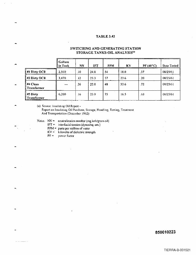
TABLE 3.42
SWITCHING AND GENERATING STAnONSTORAGE TANKS-OIL ANALYSIS(')
II~a~:~~ NN 1FT PPM I KV I PF (40°C) Date Tested ~
!I #1 Dirty OCB J[2,560 '1,10 24,0 54 18.0 ,37 I 08/25/61
:[#3 Dirty OCB I 3,470 11,12 23.3 57 23.6 ,20 I 08/25/61I
,
; #4 Clean --- ,26 22.0 48 33.6 .72 08/25/61Transformer
#5 Dirty 6,200 ! ,16 23.9 75 16,5 .63 08/25/61i Transformer ~
(n) Source: Insulating Oil Report -Report on Insulating Oil Purchase, Storage, Handling. Testing, TreatmentAnd Transportation (December 1962)
Notes: NN:= l1eutrnliz:ltionnllmber (mg.koh/gr:l11l oil)IFT:= interfncialtellsion (d)llcs/sq. em.)PPM:= pnrls per million ofw:ltcrKV:=' kilovolts of dielectric strengthPF := power factor
850010223
TIERRA-B-001521

850010224
TIERRA-B-001522

It)NNo"r"'"ooIt)CO
I..I..
I
.. 1enxd
,- -~-,_._.. : -~'~~;.-"'--:.:.:.-: .
I.I
..,I ____________
FROM U.S.C.IrG.S. JERSEY CITY QUADRANGLEDATA MEETS NMAS FOR ," ==200' MAPPING NOT-TO-SCALE
ESSEX GENERATING AND SWITCHING STATION
TIERRA-B-001523

THIS MAP CAN BE FOUND IN THE SITE FILE LOCATED AT: U.S. EPA SUPERFUND RECORDSCENTER, 290 BROADWAY, 18TH FLOOR, NY,NY 10007
:-_ 04 _ __ ••••••• u •••••••••••• H .
: :
~ i~ i~ ~: :~ ~~ ~: :; .:
~ ~~ .:: !: ~~ i! O~ .. 5111P~CI1ON 1. "ESSEX GENERATING 6: SWITCHING .i. ST A TJON" 1.
NAP Of' JOIlOPU1T
~ : CITY OF NEW ARE: IIInIA'I1m IN TIm """EX ,.'....,., COUNTY, N.J.ICA1&I'- _ Al/G.f,1W9
850010226
TIERRA-B-001524

THIS MAP CAN BE FOUND IN THE SITE FILE LOCATED AT: U.S. EPA SUPERFUND RECORDSCENTER, 290 BROADWAY, 18TH FLOOR, NY,NY 10007
r················_·············_···················_·· .._.. ..._........:
: :
I I~ :
I I~ ~: :~ ~: :: =i ~: :: :: :: :: :
NOI DATE I DESC~I~TION IDWN ICKD
REVISIONoPS~G ~C ServIce". :. ~=.Gas
""~::.'U -ft-ViY:.~.ik'? .......:p,p·~" -13~
ESSEX GENERATING.. AND
SWITCHING STATIONCITY OF NEWARK ESSEX CO. N~
"
' .RESPO ';,;~~~;/'"'bl,~;(:,} EPA NSE·:"':):'d'';Y'':}';". .' ,~~::~~~j(~~t~~~~;~1:~:~~_:;:.
CADO NO DATE JULy 30, "9i SCALE r· 100'
FI.£ CHECkED [XAWlNED
850010227
TIERRA-B-001525
THIS MAP CAN BE FOUND IN THE SITE FILE LOCATED AT: U.S. EPA SUPERFUND RECORDSCENTER, 290 BROADWAY, ISTH FLOOR, NY,NY 10007
r···················································· ······1
NO D£SCRlf'TlON DWN CKO ;
REVISION
NEWARK ESSEX CO.N-J.
ESSEX GENERATINGAND
SWITCHING STATION
EPAr. eo'NO
:. u u !
850010228
,.c,_-....-
TIERRA-B-001526

THIS MAP CAN BE FOUND IN THE SITE FILE LOCATED AT: U.S. EPA SUPERFUND RECORDSCENTER, 290 BROADWAY, 18TH FLOOR, NY,NY 10007
r" - o· 04 " " u·" oow " •• "" - ·n .- ~
~ ~: :
~ ~
, !
i:. _ J
I I I INO I DATE I DE5CR.TION IDWN ICIC.D
REVISION
0PS~GP1J)IIc StrvlceElectrIc .. Goa-C~
• eo; .' _· .... F· .' ," ".1"""""" .' . "J"o'~';;mJ~.::-:_.:,u 'ft VE, 'Va>'. ~,M.:A.·P-....'c· No. :-:'~:;,'~:.;..t,... ,- . .
-
ESSEX GENERATINGAND
SWITCHING STATION-
CITY OF NEWARK ESSEX CO. N.J-
","EPA ,RESPO NS EMJ;,!¥~!ljfi~ijtNO AUWST 13"~96 SCAlE r· eo"
CAtlD DATEFLE CHECIlED EX AlolINED
850010229
TIERRA-B-001527

THIS MAP CAN BE FOUND IN THE SITE FILE LOCATED AT: U.S. EPA SUPERFUND RECORDSCENTER, 290 BROADWAY, 18TH FLOOR, NY,NY 10007
~ on _ ·04 ~ 0 u.O •• 'O __ ~
1 !
!, ............................................................................................................................ ~ - u :
I I I INO I onE I DE:lCNIPTION I OWN ICKD
REVISIONoPS~G ~c ServIce-
_"." . '~' c." ~=..Gas .,~;,'8,U " Y ,.E~i'::al"1~·,..;:AcP::~~i N;o-_
-
ESSEX GENERATINGAND
SWITCHING STATIONCITY OF NEWARk . ESSEX CO. N..J..•·ft;?:: •.·.. EPA RESPONSE§jlf$~i;ifS'...·...•?~3"c •.: . .;~j@:~~'i:;'
.
CADI) NO DATE AUGUSt 13.1996 SCAlE r· 10'
FLE CHECKED EXAIolIl€D
,······· ..··..·.· _ -H~···..···········1
850010230
TIERRA-B-001528

THIS MAP CAN BE FOUND IN THE SITE FILE LOCATED AT: U.S. EPA SUPERFUND RECORDSCENTER, 290 BROADWAY, 18TH FLOOR, NY,NY 10007
: ••• ~ u •• + ••• ~ 1
: :~ ~[NO DESt:IIIP'TIOH DWN eKD j
REVISION
Plblle ServlciElectric • GoaC<JCI1)CI'IY
ESSEX GENERATINGANDSWITCHING STATION
RESPONSEA UGUS T 13. 1996 ,- 10'
.:. u u u :
! ,
850010231
TIERRA-B-001529

FUEL·lNrTIALL Y COAL-OlL rN LATE 40s
FLUE GAS TOATMOSPHERE
FUELLOW PRESSURE
ArR BOILERS TYPICAL
r-----------e__.-lL..- OF 24
BOITOMASH
BorLERCITY WATER
WATER CHEMICALS
HANDCARTSTO ASH PIT
OPEN HEATERDEAERATOR
Figure 3.1 Process Flow DiagramLow Pressure Turbine/Generators and Boilers
19] 5 - 1978
LOW PRESSURE STEAM
ASH SLUICE WATER
)f! NON-eONTACT COOLrNG WATER - IN
NON-eONTACT COOLrNG WATER - Olf[
ASH PIT
BorLERFEE DPUMP
MISCELLANEOUS STREAMS• CHEMICAL CLEANING WASTES (INFREQUENT)• BUILDING FLOOR, ROOF DRAINS• STORM DRAINS (SOME DIRF.CTI..Y TO RIVER OllJERS
TO NON~ONTACT COOLING WATER DISCHARGE)
--, ..
SANITARY WASTESILABORATORY DRAINS
CONDENSER,TVPrCAL OF6
CONDENSATE
ASH PIT EFFLUENT rASH HAULED OFF-srTE
WASTES
NEWARK SANITARY SEWER(INITIALL Y TO crSTERN)
850010232TIERRA-B-001530

Figure 3.2 Process Flow DiagramAddition of Unit No.7 High Pressure Turbine/Generator & Nos. 25 and 26 Boilers
19~7 - 1974 HOT FLUE GAS ourLOW PRESSURE BOlLER SYSTEM ... ,~ HlGH PRESSURE Bon.ERS 25 AND 26 SYSTEM
I
I
I,I.
FLUE GAS TOATMOSPHEREFUEL
-INITlALL Y COAL-OIL IN LATE 40s
FUELlOW PRESSURE
BOILERS TYPICALOF 16
AIR-_~
BOITOM ASHBOILERWATER
CHEMICALS oHAND CARTSTO ASH PIT
CITYWATER
LOWPRESSURESTEAM LOW PRESSURE STEAM
HIGH PRESSURETIJRBINEIGENERATOR
UNITS 25 AND 26BOILERS
*ASH TO ASH PIT ~_ ....... ...
BOILERBLOWDOWN(CONTINUOUS) **
CONDENSER,TYPICAL OF 6
NON-eONTACT COOLING WATER-IN
NON-CONTACT COOLING WATER· ourBOILER MAKEUP WATER
SURGETANK IY- ASH SLUICE WATER
BLOWDOWN PIT
AIR IN
ASH PITBOILER
FEEDPUMP
MISCELLANEOUS STREAMS• CJmMlCAL CLEANING WASTES (INFREQUENT)• Bun_DING FLOOR, ROOF DRAINS- STORM DRAINS (SOME DIREC1L Y TO RIVER OmERS
TO NON-eONTACT COOLING WA'ffiR, DISCHARGE)
( SANITARY WASTESILABORATORY DRAINS
ASH PIT EFFLUENT
WASTES
NEWARKSANITARYSEWER
NOTE: * ASH TO ASH PIT 1938 TO 1947 AFTER 1947 ASH SENT TO ASH I.AKE(S)* * BOILER BlOWDOWN NORMALL Y SENT TO L.P. BOILER OPEN HEATER.
INTERMmENTl Y TO NON-CONTACT COOLING WATER DISCHARGE..
850010233TIERRA-B-001531

Figure 3.3 Process Flow DiagramAddition of New Unit # 1 and Ash Lake
IN FLUE GAS OUT 1947 - 1978 *AIR t I •
1
171 "'-:--E-LE-C-T-R-O-ST-A-T-IC-''''AIR HEATER I / I PRECIPITATOR
j
FLUE GAS TO ATMOSPHERE
FUELS-NATIJRAL GAS-COAL·OIL
NOTE: * UNIT #1 WAS ADDED, BOILERS 25 AND 26 CONTINUED INOPERATION, LOW PRESSURE STROKERS-BOlLERS REDUCED TOTO 12 BOILERS IN 1946 AND REDUCED TO 8 BOILERS BY 1954 .
* * BOILER BLOWIJOWN NORMALLY SENT TO L.P. BOILER OPENHEATER, INTERMITTENTLY TO NON-CONTACT COOLINGWATER DISCHARGE
HEATEDAIROUl'
FLY ASH REINJECTION1I0TFLUEGAS
1HIGHPRESSURESTEAM
BOILER BLOWDoWN
II FUEL
UNIT # 1 BOfLER
LOW PRESSUREBOILER CONDENSATE
BOILER WATERCHEMICALS
~
UNIT ITIJRBINE
1 GENERATOR
NON-CONTACT COOLING WATER - rN
II PASSAIC\ RIVER
==t. ~
LOW PRESSURESTEAM
CONDENSATE
BOTTOM ASHDEAERATOR
L.~~ CONDENSER NON-CONTAcr COOLING WATER - our
HEATER(S) I ... ASH QUENCH AND SLUICE WATERASH SLUICE WATER FROM + ILOW PRESSURE BorLERSAND BOILERS 25 AND 26
~ [ ASH LAKE(S)ASH LAKE EFFLUENT
~II ASH HAULED OFF-SITEMISCELLANEOUS STREAMS• CHEMICAL CLEANING WASTES (INFREQUENT)
WASTES• atTn.DING FLOOR. ROOF DRAINS• STORM DRAINS (SOME DIREC'IL Y TO RIVER OTHERS
TO NON-CONTACT COOLING WATER DISCHARGE)NEWARKSANITARY SEWERSANITARY WASTF:SILABORATORY DRAINS
850010234TIERRA-B-001532

PORTABLEDEMINERALIZER
TRAILER *
FUELS
• NATIJRAL GAS• KEROSENE• DiSTILLATE
figure 3.4 Process Flow DiagramSimple Cylce Combustion Turbines
1963 - PresentNOx SUPPRESSIONWATER INJECTION EXHAUST TO ATMOSPHERE
MISCELLANEOUS STREAMS• STORM DRAINS
93MWTOTAL (ONE UNIT) * *
194MWTOTAL
212MWTOTAL
EXHAUST TO ATMOSPHERE
fUELGAS ONLY
EXHAUST TO ATMOSPHERE
90MW
EXHAUST TO ATMOSPHERE
PASSAICRIVER
(4 GENERATORS!8 COMBUSTIONTURBINES)
212MWTOTAL
EXHAUST TO ATMOSPHERE
FUELGAS ONLY 36MW
(4 GENERATORSI8 COMBUSTIONTURBINES)
EXHAUST TO ATMOSPHERE
WASTES
(4 GENERA TORSI8 COMBUSTIONTURBINES)
NOTE: *REGENERATED OFF-SITE* * NEW UNIT 9 REPLACED OLD UNIT 9 IN 1990
850010235TIERRA-B-001533

850010236
-.
TIERRA-B-001534

ATTACHMENT I
HAZARDOUS AIR POLLUTANTSESSEX GENERATING STATION
The two major types of electric generation processes used at the Essex Generating Station wereSteam Electric and Combustion Turbine. The two major emission sources associated with theseprocesses were boilers fired by either coal, oil or gas in the case of Steam Electric and combustionturbines fired by gas or oil.
Station specificdata for Hazardous Air Pollutants (HAPs) are not available. To provide an estimateof the potential HAPs generated at Essex the following (coal-, gas-, and oil-fired boiler and gas-firedcombustion turbine) emission factors and combustion turbine distillate emissions analyses areprovided from both the EPRI PISCES Database (ref 1), and relevant literature (ref2).
Fuel Fired Boilers
Tables I-I through 1-5 list emission factors for hazardous air pollutants for coal-, oil·, and gas-firedstearn-electric power plants that were prepared for the Electric Power Research Institute "EPRI" byRadian Corporation.
The emission factors for coal-fired units are divided into three groups:
1. particulate-phase emissions (Table 1-1),2. vapor-phase inorganics such as Hydrochloric Acid (HCl), and Hydrofluoric Acid (HF) mercury,
and, in some cases, selenium (Table 1-2),3. organic substances (Table 1-3)
Uncontrolled oil-fired boiler emission factors are presented in Table 1-4 for particulate-phaseemissions, vapor-phase inorganics, and organic substances. A limited data set was developed for oil-fired boilers with normally operating electrostatic precipitators (ESPs). Based on this data, EPRlrecommends 60% of the values in Table 1-4 for the metals Arsenic (As), Beryllium (Be), Cadmium(Cd), Chromium (Cr), Cobalt (Co), Lead (Pb), Manganese (Mn), and Nickel (Ni) for oil-fired boilerswith ESPs. For organic substances and volatile elements Mercury (Hg), Selenium (Se), HydrochloricAcid (HCI), and Hydrofluoric Acid (HF), the values in Table 1-4 are appropriate for oil-fired boilerswith or without an ESP.
There is limited data available from the EPRI Field Chemical Emissions Monitoring (FCEM) Projecton HAPs emissions from gas-fired boilers. The corresponding emission factors for gas-fired boilersare presented in Table 1-5.
AlTAClfMENT I Page 1
850010237
TIERRA-B-001535

The HAPs emission factors were derived from recent test data produced by EPRI and the U.S.Department of Energy "DOE" that focused on HAPs. The emissions estimating methodology waspresented in reference 1,by Radian with the following caveats:
Actual measurements of HAPs emissions can vary from estimated levels by several orders ofmagnitude. This variability is primarily external to sampling and analytical variability (i.e., it iscaused by site-specific differences in plant design and operation and in daily process variability).Emission estimates developed from such data distributions may differ significantly from measuredvalues.
As more data become available and are used in the regressions and averages, the predicted factorsmay change.
Much of the data fit log-normal distributions. The resulting correlations and geometric meanvalues provide an appropriate median emission factor for a single unit.
Site-specific factors at any given plant may be so different from the sample population used toproduce these equations that the predictive value may be compromised. For example, co.firingwaste tires with oil was not examined at any test site. The oil emission factors would not be goodestimators for emissions from such a plant.
It should also be noted that the field data used to develop emission factors for coal-fired boilers wereobtained from wall-fired, tangential- fired, and cyclone boilers/furnaces equipped with particulateand/or flue gas desulfurization (FGD) systems. The low pressure, stoker-fired boilers (Nos. 1 through24) at Essex utilized a different boiler type than the FCEM test units and were not equipped with airpollution control systems.
Combustion Turbines
Measurements of HAPs for utility combustion turbines were performed by Carnot for the ElectricPower Research Institute's (EPRI) Gas PISCES (power Plant Integrated Chemical Emissions Study)field measurement project. The program was jointly sponsored by EPRI and the Gas ResearchInstitute (GRI). The two utility combustion turbines tested by Carnot included the Westinghouse50lAA combustion turbine, without NOx controls, and the General Electric Frame 7 combustionturbine equipped with water injection for NOx reduction. The HAPs testing for the two utilitycombustion turbines included measurements of trace metals, semi-volatile organics, and volatileorganics.
The results of the metal tests on the two utility turbines are presented in Table 1-6. The test resultsare reported in three discreet groups on each unit: those detected at more than twice the field blanklevels, those detected at less than twice or below the field blank levels, and those that were notdetected. The measured levels were all low compared to emissions from coal- and oil-fired boilers.
ATTACHMENT I Page 2
850010238
TIERRA-B-001536
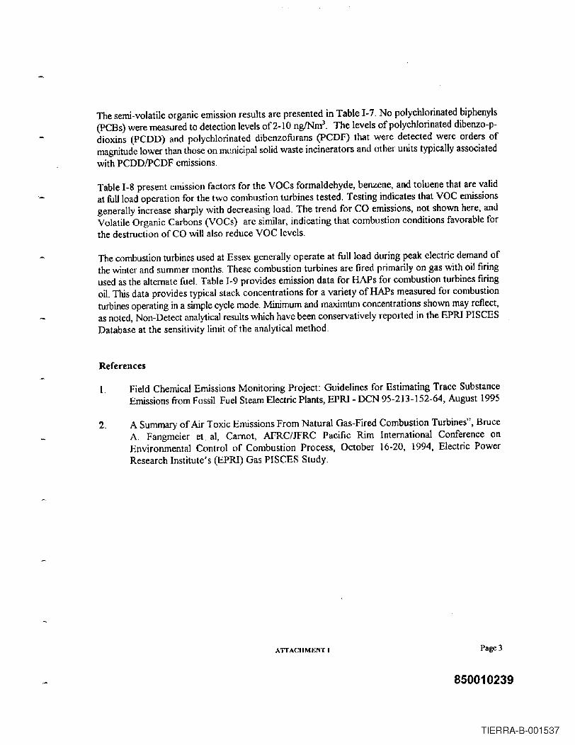
The semi-volatile organic emission results are presented in Table 1-7. No polychlorinated biphenyls(PCBs) were measured to detection levels of2-1O ngINml
. The levels of polychlorinated dibenzo-p-dioxins (PCDD) and polychlorinated dibenzofurans (PCDF) that were detected were orders ofmagnitude lower than those on municipal solid waste incinerators and other units typically associatedwith PCDDIPCDF emissions.
Table 1-8 present emission factors for the VOCs formaldehyde, benzene, and toluene that are validat full load operation for the two combustion turbines tested. Testing indicates that VOC emissionsgenerally increase sharply with decreasing load. The trend for CO emissions, not shown here, andVolatile Organic Carbons (VOCs) are similar, indicating that combustion conditions favorable forthe destruction of CO wiU also reduce VOC levels.
The combustion turbines used at Essex generally operate at full load during peak electric demand ofthe winter and summer months. These combustion turbines are fired primarily on gas with oil firingused as the alternate fueL Table 1-9 provides emission data for HAPs for combustion turbines firingoil. This data provides typical stack concentrations for a variety of HAPs measured for combustionturbines operating in a simple cycle mode. Minimum and maximum concentrations shown may reflect,as noted, Non-Detect anal}1icalresults which have been conservatively reported in the EPRI PISCESDatabase at the sensitivity limit of the anal}1ical method.
References
1. Field Chemical Emissions Monitoring Project: Guidelines for Estimating Trace SubstanceEmissions from Fossil Fuel Steam Electric Plants, EPRI - DCN 95-213-152-64, August 1995
2. A Summary of Air Toxic Emissions From Natural Gas-Fired Combustion Turbines", BruceA. Fangmeier et aI, Carnot, AFRC/JFRC Pacific Rim International Conference onEnvironmental Control of Combustion Process, October 16-20, 1994, Electric PowerResearch Institute's (EPRI) Gas PISCES Study.
ATTACHMENT I Page 3
850010239
TIERRA-B-001537
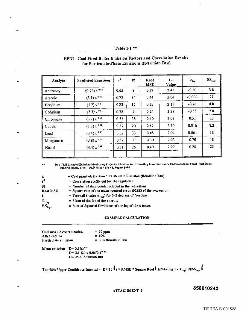
Table 1-1 "'"
EPRI - Coal Fired Boiler Emission Factors and Correlation Resultsfor Particulate-Phase Emissions (lb/tri1lion Btu)
Analyte
Antimony
Arsenic
(0.92) X 0.63
(3.I)xo.S5
2.45
2.04
Beryllium 2.13(l.2) X \,1
(3.3) x 0.5Cadmium
II Chromium
2.37
(3.7) x 0,58
II Cobalt (1.7) X 0.69
II Lend (3.4) X 080
II Manganese
II Nickel
II(4.4) X 04S
0.016
0.061
0.70
0.28
3.8
27
4.8
7.8
23
8.3
18.
18
25
Ref; Ficld QleJlucaJ Emlssiolls MOllilOliJlEProject: Guidelines for Estlnl3th,C T ....ce Substance Emissions from FossU Fuel SI......Electric Plants, ErRI - DeN 95-213·152-64, Augusl 1995
xr2NRoot MSEt
= Coal ppm/ash fmetion - Particulate Emission (lb/million :Btu)= Correlation coefficient for the regulation= Number of data points included in the regression= Square root of the mean squared error (MSE) of tbe regression= Two-tail t value (to.02S) for N-2 degrees of freedom= Mean of the log of the x terms= Sum of Squared Deviations of the log of the x terms
EX~~LECALCULATION
Coal arsenic concentrationAsh FractionParticulate emission
= 20 ppm= 10%= 0.06 Ib/millioll Blu
MeanernissioD E= 3.l(X)0.1SE= 3.1 (20 x 0.06/0.1)°·15E = 25.6 Ib/trillion Btu
The 95% Upper Confidence Interval := E * to°( t * RMSE * Square Root { IIN + ((log x - x 1o&)'2)/SSIop )}
ATTACHMENT I 850010240
TIERRA-B-001538

Table 1-2 **
EPRI - Recommended Emission Factoras Percent of Coal Input
Bituminous Coals
Emission Control Number of Average 95% Confidence RecommendedDevice Sites Reduction Interval Emission Factor
as Percent of Coal
II Mercury I 1 I
Input
ESP 17 26% I ±14%II
70%
II Mercury I None 1 --- I ---",
--- I100%
II Selenium I None 1 15 I 45% I ± 13% C 55%
I Hydrochloric Acid None 1 15 I -1%
I± 13% I 100%
\I Hydrofluoric Acid I None ] 12 I 11% ± 19% I 90%
,
Ref; Field Cbemlcu.l Emission .. Monlcorl.ne: ProJet:e: Guideline. for EsU.nu.tln£ Tru. Substan •• Enu..loll& from Foull Fu.1 S": .....EleeCrlcPlaJ,c..,EPRI· DeN 95-213-152-64, Aue:ust 1995
ATIACHMENT I850010241
TIERRA-B-001539

Table 1-3 **
EPRI - Coal-Fired BoilerOrganic Substance Emission Factors (Ib/trillion Btu)
Chemical SubstanceSites
Tested
I-Chloton"phtll~lene
SitesDetected
12 2.0
oMean VCI
<7.8
I-N~phlhylamine 8 0.011
1,1- Dichlotoelhane 12
l,l·Dichlotoelhane 12
12I, I ,2-TtichloroelhiUle
1,1,2,2- Tettachloroelhane 12
o
oo
D 0.89 0,40
1,2.Dibromomelhane 2
1,2-Dichlorobenzene oo
11
1,2-Dichloroethane 9
1,2.Dichloropropane
8
12
1,2.Diphenylhydra2.ine
1,2,4· TrichlotoheJi2.ene 9
1,2,4,5- Tewchlorobcnzene g
1,3-DichlorobellZene II
2 1 D 2.6 0.0 1.3e+O.6
~I 'I <0.2 I <3.5
oo
E
E
E
<0.4
<0.4 . '1' ..... <6
<2.4 <33
<S.2
1.0
0.3
<0.15
0.24
8.6
<5
1.1 0.25
E
cA
o
o
oI
o4.4
1,4-Dichlorobenzene II
5.42
11 1 D
~I2-Chloron~phlh"lene 8 2
II
2·DUlllnone II
4.8
3.1-
I
7
2 -Cbl ofophenol 6
2 C 0.0005 0.0 0.017
2·Hexanone 10
o o3.2
<0.2
1.8
<5
S.7
2·Melhy!naphtllalene 19
<7.8
3 10
0.036 0.017 0.0778
2.Melhylphenol g
<5
o oo E <O.H
J <1.81 E I
If--_II2-Naphlhylamine 7
2-Nitroaniline
2-Nitropbenol
2·Picol;"e
7
9
92,3,4,6· Telrachloropbenol
2,3,7,B-TCDD equivalents 10
ooaao
o
E
A 0.000002
<24
<7.8
<7.8
4.40..07 0.000012
<16o10 10
2,4-Dichlorophenol 9 ooo
92.4.Dimelllylphenol
2,4·Dinitrophenol
2,4·Dinittololue"e 13 4
ATTACHMENT I
0.94
850010242
TIERRA-B-001540

Table] -3 (Continued)
EPRI - Coni-Fired BoilerOrganic Substance Emission Factors (Ib/trillion Btu)
Siles Sample!
Lo2-NormalSUesCbemical Substance Tested Detected Size DQ*
UCUMean LCI,I 2,4.5·Trichlorophenol 9 I 0 I 0 E <0.12
~II 2,4,6- Trichlorophenol 9 I a I 0 E <0.12 <7.8
I2,' -Dimelbylbenzaldehyde 2 2 2 C 14 9.1 , 23
2.6-DicWorophenol 9 0 0 E <0.19 <7.8
II 2.6·Dinitrotoluene 13 2 I 8 D 0.11 0.0095 1.3
II 3 ·Chloropropylene 2 2 2 C 9.1 5.5I
15
II 3.Melbylcholanthr.ne 10 0 I 0 E <0.005 <7.8
I 3 -N iltoeniline 9 0 F' E <0.14 <39
3.3-Dichlorobenz.idine 9 0 E <0.13 <16
3,4-Melhylphenol 2 2 2 C 0.71 0.21 2.01
4.Aminobiphenyl 10 0 0 E <0.27 <7.8
I 4-Bromophenyl phenyl .!her 9 0 0 E I <0.14 <7.8
II I ~4-Chloro·3 -m.!hylphenol 9 I 0 I 0 E . <0.19 ~<7:8
I.-
4.CWorophenyl phenyl elher 9 0 0 E <0.14 <7.8
I4·EII,ylloluene 2 2 2 C 2.8 0.0001 1.3e-t{)'
4·M.lhyl.2.pe"lanone 7 2 6 D 2.3 1.1 4.7
II I ~4.Methylphenol 9 I 2 1 6 D 1.3 1.1 I U
4·N iltoani Iine I 9 I 0 l 0 ~ <3.5 i <39I
4.Ni1rophenol I 9 I 0 () -H--t--I <0.23 <39
4,6-Dinillo-o-cresol I 9 I a 1 11 <0.2 I <39
I I 1 ~I--
5.Methylclvysene 3 I 3 0.0001,
0.00'4
7H-Dibenzo{ c,g)cart:>azolc 3 0 0 -H--t--r <0.001 <0.016
7,12-Dimelhylbenzo(n)anllvacene I 10 I 0 1 0 <0.005~--
Acennphlhene 24 11 IS A 0.024 0.011 0.050
Acennphlhytene 24 12 13 A 0.0078 0.0044 0.014
Acel3ldehyde I 19 I II 19 A 3.2 Ll [ 8.9
Acelone II 3 II C 1.1 0.37 3.2
Acetophenone 15 8 14 A 1.2 0.74 ~
Acrolein I 12
I5 f+FR 1.9
~
7.2
Aniline 9 a <0.24 <7.8
Anthmcene I 24 I II 1 15 A 0.013 0.00S4 0.030
ATTACHMENT I
850010243
TIERRA-B-001541

Table I -3 (Continued)
EPRI - Coal-Fired BoilerOrganic Substance Emission Factors (Ib/trillion Btu)
Sites Sites I S.m.', Lo~-NormalChemical Substance Tcsted Detectcd Size DQ"I IMcan LCI UCI
II BenzAldehyde I 7 I 2 I 7 o 1 4.2 I 0.83 21
~
Bcnune I 25 I 23 I 25 ~I 1.9 8.0
Benzidine
I
10 1 0 I 0 ~I <2.4 <7.8
Bell20ic acid 11 1 5 I 11 ~il 9.5 53
i~ Benzo(a)nJ1lhracene 27 '1 11 I IS ~I 0.0032 0.017
il
Benzo( a)pyrene 27 R=F+= B 0.0019 0.0008 0.0045
Benzo(a)p)'l""le equivalents 11 11 11 A 0.0048 0.0019 0.012
~ Benzo(bj&k)tluoranthene I 26 1 10 I 14 A 0.0096 0.0040 0.023
'I Iknzo{ e)pyrene 7 4 7 C 0.0036 0.0013 0.010
III Benzo(g.h,i)perylene I 26 1 6 I 12 ~I 0.0007 0.0031
"
Benzyl alcohol
I9 R=R=FR 2.0
~
2.9
&nzylchloride 6 0.28 0,0042 19
ill Biphenyl I 9 1 6 I 9 ~l 0.022 I 1.2 !
I bis(2-ChloroethoK'j)meU1ane 8 0 0 r+t--, <0.17 <7.8I
ill bis(2-Chloroethyl)ether I 9 I 0 I 0 <0.18 I <7.8
Ibis(2-Chloroisopropyl)ether 10 R=R=FR ~
<7.8I i
bis(2oEthylheK'jl)phthalllte 11 3.6 2.0 6.2
Bromodichloromethlllle 10 0 0 E <0.49 <6
III
Bromoform 10 0 0 E <0.42 <10
Bromomelhlllle I 13 '1 4 I 13 I C I 0.89 I 0.38 I 2.1
!II Butylbenzylphthalate I 9 1 2 I 2 fClO3Ol 0.24 I 0.38
II Carbon disulfide I 14 1 7 I 13 ~I 0.40 I 2.9
Carbon letrachloride 14 0 0 E <0.42 <6
i Chlorobemene 15 I I I fDI 0.16 I,
II Chloroel.hane I 13 I I II I 0 1 0.53 0.26 1.1
II Chlorofonn I 12.,
I I II ~I 0.26 I 1.2
Chloromethane 10 J 10 C l.l 0.23 5.1
I Chrysene 26 9 12 A 0.0055 0.0028 0.011
I cis-I,200i chloroethene 6 0 0 E I <0.42 <3.1
I cis· I ,300icllloropropene 14 I 14 D 0.72 JIll7 1.4
Crotonaldcllyde 4 0 0 E <0.1 <7.1
ATTACHMENT I
850010244
TIERRA-B-001542

Table I ·3 (Continued)
EPRI· Coal-Fired BoilerOrganic Substance Emission Factors (Ib/trillion Dtu)
Chemical Substance
a
SitesTested
SitesDetected
SampleSize
E
1.6
Mean
Log-Normal
I LeI I UCI
Dibenzo(a.e) pyrene------------- ----+-----IR=I-----1f----+------1f-------11Dibenzofurnn
Dibenzo(a.h)ncridine 3
26
3
3
Dibenzo(a.hp,nUll"lICene
Dibcnzo(o,i)acridine
Dibenzo(o,i)pyrcne
14
3
4
a3
I
o
DibromochloromethlUle oDibcnzo(aj)acridine 9 o
Dibutylphthalale
12
9
DichlorobromomeUlane
D ;ch]oromethane
2
2
o
o
c
E
D
D.S8
0.11
0.21
<0.0003
<0.001
0.0003
<0.001
<0,2
<0.42
<0.003
<0.002
0.0024
<0.004
<0.45
<7.8
28
<2
<40
Diethylphlh:llalc 10 2
Dimethylphenelhylanline 9
9
o
Dimelhylpbthalate
2
E
<7.8
c
<0.42
<1.6
0.20
0.0005
0.020 2.0
E
D
<2.4
0.00.090 I.Oe+03
Di-n-bulylphthalale 3 o o E <1.9 <3
<7.11
Di-n-oClylphlh:llale o o
Diphenylamine
Ethyl methanesulfonnle
9
9
Ethylbenzene 16
FluoranU,cne
F1uon:ne 24
oo4
<0.21
<0.13
<0.17
0.35
I1-
<7.11
1.8
0.39
0.40
13
II
0.OS9
0.049
4.8FOffiluldehyde 26 10
a E
1.4
<0.001 <7.8lJeuchlorob<:nzene
JJ
13
14 o26 B 2.6
Hexuchloroouladiene
HelUl.ch]orocyclopentadienc
Hexachloroethane
IS
Indeno( I .2,3-c.d)pyrene 25
Hexaldehyde
lodomcthane
Isophorone 10
2
o
oo
7
2
o ~.8I <0.001 I <7.8o
o2
12
2 C 2.0
I <0.001 I <7.8
5.7 I 0.0036 [ 9.20+03
0.0017 I 0.0008 I 0.0039
7Methyl chlorofonn 8 3
10
AITACHMENT I
0.0
0.32
0.24
2.30+09
850010245
TIERRA-B-001543

Table I -3 (Continued)
EPRI - Coal-Fired BoilerOrganic Substance Emission Factors (Ib/trillion Btu)
I
Sites Sites Sample Loll.NormalChemical Substance Tested Detected Size DQA I IMean Lei UCIMelhyl rnell1l1crylale I 2 I I I 1 D 1.1
Methyl rnelllllJ1esulfonQ\e I 9 I a I 0 E <1.2 <17
Methylene chloride I 7 I 4 I 7 C 3.6 0.63 21
mlp- Tolualdehyde I 2 I 2 I 2 C 3.2 0.0012 8.40+03
1 mlp-Xylene 13 8 13 A 0-82 0.28 2.4
Naphthalene I 23 I 12 I 20 A 0.62 0.36 l.l
n-BUlyraldehyde I 2 I I I 2 D 8.3 0.0001 5.ge+05
n-Hexane 2 2 2 C 0.49 0.0 1.70+06
Nitrobenzene 9 0 0 E <0.19 <7.8
N- Nilrosod ibutylamine I 6 I 0 I 0 E <2.4 <7.8I
N.NilTosodimethyl amine I 10 I 0 I 0 I"EI I <0.34 I <7.8
N -Nitroso-di-n-bulylamine 3 0 0 E <0.32 <5 I
N.NilTosodiphenylamine
I9
I0 R= E <0.14 <7.8
I
N.NilTosodipropylamine 9 0 E <0.21 <7.8
I N-NilTosopiperidine 9 0 0 E <0.24 <7.8
0-Tolualdehyde 2 I 2 D 2.9 0.0 6.0e+06
o-Xylene I 12 I 3 I 12 JCl 0.44 I 0.25 I 0.78
p·Chloroaniline I 9 I 0 I a JEI I <0.18 I <7.8
p. Dirnelllylaminoazobenzene 9 0 0 E <0.11 <7.8
Penlachlorobenzene
I9
I0 R= E <C.ll <7.8
Penl<lchloronilTobenzene 9 0 E <0.54 <7.8
Pentachlorophenol 13 0 0 E <0.001 <39
Pcrylene 2 1 2 D 0.0035 0.0 7.2e+15
Phenacelin I 9 I 0 I 0 E <C.O 14 <7.8
Phenanlluene 24 13 24 A 0.42 0.19 0.91
II PIlenol I 13 I 7 I 13 B 3.3 J.S 7.1
II Pronamide I 9 I 0 I 0 E <0.17 <7.8
'1IProPllJ1al I I I ro-I I I...
2 1 3 2.3 0.0 l.1e+06I Propionaldehyde 6 4 6 C 1.8 0.11 30
Pyreoe 24 10 21 B 0.066 0.022 0.19
I Pyridine 9 0 0 E <0.28 <7.8
ATTACHMENT I
850010246
TIERRA-B-001544

Table I -3 (Continued)
EPIU - Coal-Fired BoilerOt"ganic Substance Emission Factors (Ib/trillion Btu)
o4
SampleSize
SitesDetected
SitesTestedChemical Substance
o12
3
16
Quinoline
Styrene
15 3 10Te!Tachioroethylene
23
oToluene 23 16
otrans-I,2 -Diehl oroetllene
!Tons-I,3.0ichloroprorene
12
14 o oo oTriehloroetllylene 14
Trichlorofluorometh:me 5
I
12
Trichloromethlll1e
II Valer"ldehyde
II VinylllCeule
II Vinyl ehloride
2
2 2
3
12
13
12
•• n.f; Field C'hem.kal EmissIons Moni!orill2 Project: Guiddines for Estlmatlna: T .... c. SubstJlllce Emissions f"om Fossil Fuel Steam E1cclrirPlants,EPRI· DCN '5-2]]-152-64, AUlDS! 1995
• Data quallty:
A ~ Five or more det .. t.d values, no more than 500/. nondeterts bl sta11stles.B - Four e>rmore detected values, no more th ..1167% nondctects In sbtlstles.C - T"'o or more detecled vll1u.~ no mort than 75% nondetects In .b1llsties.D - One or mort ddeclcd valu.s, no Umit on nond.l.cts III statlstks.E - Substan" has nol been delected.
1£1 - Lower Confld •••ce Int.rvaltJCI- UpperConl1dence tnten'llI
AIT ACHI\'IENT I
850010247
UCI<5.6
1.4
0.75
<6.9
2,3
TIERRA-B-001545

Table I~4 **
EPRI - Uncontrolled Oil-Fired BoilerEmission Factors (lb/trillioD Btu)
II ~rue
SitesTested
13
Chemical Substance
13
Beryllium
II Cadmium
II Chloride (as lIel)
I'--chromium1~~1I~-----------~ Fluoride as (lIf)I:::==~.
12
13
10
13
13
SitesDetected
12
13
13
13 II
I 0.051 0.465 13
7
17
12
12 11
11 13
7 7
10 10
II 13
13 13
9 11
Nickel 14
r~::mmr:-I 2.5 I
0.15
1.2 0.42 3.1
1370 1870 3000
8.7
110 270
8.0
14
0.48
5.2 3.1
76
17
23
Selenium 17
2
1.0
l-ehiorollllphthalene
\·Naphthylam'ne 2
32 14
< 1.9I,I-Dichlorethane 2 o
2
E
o E
48
3.7
8.3
0.23
1.1 0.0074
<1.9I,I-Cichloroethene 2 o o E
<0.49
<0.49
I,I,I-Trichloroethane 2 2 c 160
<0.491,I,2-Trichloroethane I I 0 <0.48
1,I,2,2·Tetrachlorocthaoe <0.49
2
oo o <0.48
1,2-Dibromomethane
1,2·Dichlon:thane
2
2
2 o <2.1
<6.51.2-Dichlorobcnzene 2 o o E <0.49
1,2-Dichloroethane 2
2
< 1.9 I1.2-Dichloropropanc
o ooo
o
l,2-Diphenylhydrazine
1,2,4-TrichlorobellZcnc
1,2,4,5-Tclnchlorobenzene
1,3-Buladienc
2
2
<6.51,3-DichlorobellZCne 2
2
2
2
1,4-Dichlorobcnzenc
2-Bulanone
2-ChlorolUlphthalene
2
2
o ooo
o
o Eo
o
o
I <0.49
<0.49
<5.9
~5.9
I <5.9
I <0.14
E
E
2 E
4 <4.8
112-chloroPhenol
o o
E <5.9
<5.9
<5.9
<6.5 I<6.5 ]
<6.5 II
<19 I
oo oo oo o
ATTACHMENT I
E
850010248
TIERRA-B-001546

Table 1-4 (Continued)
EPRI - Uncontrolled Oil-Fired BoilerEmission Factors (lb/trillion Btu)
SitesTested
II
IC 2-MclhyIphenol
II 2-Naphlhylnmine
2
2
o2
2
SitesDetecled
9
SampleSize
9
UCI0.047
o o <5.9 <6.5
<32
o oo o
2
ooo
2
2,3.7,8-TCDD equivalents 4
<6.5
<6.5
<13
0.00012
o o
<6.5
3
o2.4-Dichlorophenol
2.~Dirn.!hylphenol
2.4-Dinitrophenol
2
2
o oo
2 oo2.4-Dinilrotoluene I
<5.9
<30
<5.9
<5.9
<12
0.000001
<5.9
<5.9
<6.5
<6.5
<32
<6.5
o2 o2
'12,6-DiChloroPhenol1.02
<30
<5.9
<6.5
o o <5.9
<5.9
<6.5
<6.5
2
f:2,6-Dinilrololuene 2
3-Mclhylcholanlhrene II
3-Nilroaniline 2
oo o E
<6.5r-;-I __ II +__ -IIr-;-I
<5.9
<5.9
0.006
E <30
<330
<32
3,3 -Dichloroben:cidine 2 E
E
<12
<5.9
<5.9
4-Aminobiphenyl 2
2
o
E
i
III
I
<13
<6.5
<6.5
o E <6.5
<5.9 <6.5
4-Chiorophenyl phenyl ether 2 o <5.9
4-Nilroaniline 2
I 0
~o
4·Melhylphenol 2
4-Nilrophenol
4.6- Dinilro-o..., resol
2
2
<16
2
7. J 2-Dimelhylbcnzo(a)all!hraecenc 11
0.029Acenaphlhcnc IS
o <5.9
o<6.5
<32
<32o
E
<30
<0.01
<0.002
0.0052
<32
2
AcelUlphlhylcne III
o o<30
<30
AccLIlldehyde
a
o4
E
0.16 270
o E
6.6
Acelone 2111------------+------:t±]11f-----1I.--+-----+----+------I1<6.5Acetophenone 2
16' c 0.012
I I D 0.0020
2 D
o
AITACHMENT I
<4.9
<5.9
850010249
<19
TIERRA-B-001547

Table 1-4 (Continued)
EPRI - Uncontrolled Oil-Fired BoilerEmission Factors (lb/trillion Btu)
Chemical SubstanceSites
DetectedoIt Acrolein
Aniline o
Bel1Zllldehyde
Benzene
Benzoic acid
II Benzo(a)anthracene
" Benzo(a)pyre~e __
II Benzo(a)pyrene equivalents
2
II Benzo(g,h.i)peryle_nc 2
Benzyl alcohol oo
<S.9
<5.9
<20
1.5
0.026
0.0086
<0.010 !
<6.S
<6.S
2 o E <6.5
oo
bis(2)-Eth y Ihe xy 1)phIh8Ia~ oBrornodechloromelhane o
<5.9
<S.9
<S.9
<6.S
<6.S
<1.9
Bromofonn I <0.48 <0.492 o o E
Bromomelhane 1 2 I 0 j ~·I £ 1 I <0.49 < 1.9
BUlylbenzy lphlha 1.le I 22
1_ .°0 I 0 I E 1 I <S 9~ I --0"1 £1 I <0.~9Camon disulfide
<6.S
< 1.9
o <0.48 <1.9Camon tetrachloride J -----4 II E I <0.34
< 1.9
° E
Chlorohenzene 4 o oCh loroeth ane <0.48E Io
<0.69
Chloroform 4 oo <0.48
Chloromethane 2 °o <0.48
<1.9
Chrysene 18 3 16 O.ooSI
I
0.0046
Oibenzofuran
<0.49
<6.S
2 ° o E
Oibenzo(o ,h )anthrace ne
Oibenzo(a J)acridille
0.0031
<5.9
<S.9
0.0069
<1.9
<1.9
0.019
<0.48 <0.49Dibromochloromethone
Dibulylphthalate E <S.9
<65
<6.S
Dichloromel11ane 2 c 33
AITACHMENT I
9.7
850010250110
TIERRA-B-001548

Table 1-4 (Continued)
EPRI - Uncontrolled Oil-Fired BoilerEmission Factors (lb/trillion Btu)
SitesTested
SitesDetectedChemical Substance
2
Dimeth ytl'heneth ylnmine 2
<6.5
Dimelil)'!phlil.Jale 2
Di-n-octylphlil.tale 2
Diphenylumine 2
Elilyl methnnesulfonale 2
1[1. DQ*· Mean LCI
SampleSize
Lo~-Normal
DCI
E
o o <6.5
<6.5
<65
<6.5
<5.9 <6.5
Fluorunlhene
0.45
0.030
0.022
Elhylbenzene
Fluorene
o o
0.014 0.0064
0.012 0.0068
Fomlaldehyde 18 7.4
0.0069 i 0.0046Indeno (I,2,3.-c,d) pyrene
o o
A
o18 43
0.010
ooo o
ooo
o
Isophorone 2
< 1.7Melb yl bromide 2
IS
E <6.S
E <1.2
Melbyl melbnnesulfonate 2 <6.S
Melbyl ehlorofonn 2 2 2 c II 0.051 2500
o o E
mlp-Xylene 2 2 2 c 1.2 0.73 2.1
Naphthalene 18 14 18 A 0.83 0.30 2.3
Nitroben2ene 2
<6.5
o o E <5.9 <6.5
N·Nilrosodlbulylamine 4 o E
<6.5N-Nilrosodimethylamine
<0.04
<0.03
IIN·Niltosodlethylamine I 2 1 0 I 0 ~I11i--------1 4 1 0 1 0 ~ ..l---t--~--ll
I FFFR=F·I------t----111<O.OS
N·Niltosodiphenylamine <6.5
<6.5N· Nilrosodip ropylamine
<5.9
<0.4
N.Niltosopipcridine 4 <6.5
N-NiltOSOmorpholine 2 o
o
E <0.4 <0.5oE <0.04
N-Nilrosopyrrolidine 2
o oE <0.04 <0.05
o-Xylene 4
<6.5 I
p-Chlorouniline 2
p·O imethyln minOllZobe n2ene 2
o ooE
E
0.35 0.15
<5.9
<5.9
0.84
<6.5
<6.S I
Pentachlorobenuone <5.9
<5.9
2 4
<6.5
Phc""cet;n
<30
<5.9
o o
<32
<6.5
18 0.092Phcnunlhrene
o
15 16
ATTACHMENT I
A 0.040 0.018
850010251
TIERRA-B-001549

Table 1-4 (Continued)
EPRI - Uncontrolled Oil-Fired BoilerEmission Factors (lb/trillion Btu)
t-_ Loa-Normal
Sites Siles SampleDQ- I . M.ean.1 LCIChemical Substance Tesled Detecled, Size vel
Phenol R=F+=I 2 R=P=~ 83
Pronamide 0 <6.5E <SJ
Pyren. 19 5 IS B 0.012 0.0064 0.024.. -- - _ .. - ..
I.- .-
1 r 1 I I IPyridine 2 0 0 E <5.9 <6.5
Styrene 2. 0 0 E <0.411 <0.49
Tetrachloroelhylene 4 0 0 E <0.41 <1
Toluene II 11 11 A 12 6.0 25
ltans-I,2-Diohloroelhene 2. 0 0 E <0.49 <1.9
trans-I,2.-0iohloropropene R=r=+= 0 E F=pg= < \.9
Trichloroelhylene 0 E <0.49 < 1.9
T rie hI oro nuoromelh ane 4 3 4 C \.7 0.23 13
Vinyl acetale [ 2 I 0 0 E I I <4.9 <19 I
Vinyl chloride 4 0 0 E <0.49 < 1.9
•• Ref; FIeld Chemical Emissions MonJtorlJlg Projed; Guldelines for EstimatIJ.g Trace Sub.tan ... Emissions front FossU Fuel Stum EledrlcPlanls,EPRI - DeN 95-213-152-64, August 1995
.Data qtlIllily:
A = Fhe or 11I0redetected valuts, uo lUore tban 50% uoudetects ill SWli~tiC5.B = Four or wore delected ,,:tIues, uo wore Ibml 67% Doudetecls ill stalillics.C = Two or 11I0redetected va!uts, uo wore tban 75% in swli~tics,D = Oue or wore detected values, uo Uwit ou uuudell'Ct.~ in swllsucs.E = SUbSUUlCe bos not been detocted.
ATTACHMENT I 850010252
TIERRA-B-001550

Table 1-5 "'*
EPRI - Uncontrolled Gas-Fired BoilerEmission Factors (Ib/trillion Btu)
SitesTested
Arithmetic MeanEmission FactorSubstances
2
SampleSize" DQ<
SitesDetected'
Anenic 2 2 c 0.23
Beryllium <0.012 o o E
Cadmium 2 D 0.04
1.1II-----E·-i--·E+---t---~II'I-----F p=,f----J----n
I 2 -, 1 2 I
Chromium
Cobalt
2
Manganese 2
Mercury'
c
D 0.08
c
C
0.4
0.4
o 0.0008
2.4Nickel
<0.02Selenium
2
2
2 2
o
c
E
0.8Benzene
o
1 o
Formaldehyde' 9 9 A 175(0-410)
10Toluene 2 2 2 C
Benzo(n)pyreneequivalents
2 o o E
2,3,7,8-TCDDequivnlents j D 0,0000012
Ref; Fjeld C'hem.ical EmIssions MonitoJin: Project: Guideline. for Estlmatin: Trace Substance Emissions f.... m FossU Fuel SteamEleclrlcPbnls, EPIU • DeN 95·213-152-64, AugllSt 1995
ab Number of times the subl;lnnec WlU quantified.
TIle nwnbec of site values used to cnlculnte the menn llIld confidence interval. (Individual values wilh detection limits greater than two timesthe highest quantified value were not included in the mel1l1.)
cDnta quality:A ~ Five or more detected values, no more than 50% non detects in statistics.B - Four or more detected values, no more thnn 67% nondetects in slnli5\i"".C - Two DC more detected values, no more than 75% nondet~ in sblistics.D • One or more detected values, no more on noodelects in stalistiCl~E ~ subsl.'IIlCCh."" not bero detected.
def
Based on natural gas analysis, not detected in slack g:lS al higher concenlrat;oR.
Median vnlue and confidence intervals are 34, 7to 150.
ND = Nol delecled.
ATTACHMENT I 850010253
TIERRA-B-001551

Table I - 6
EPRI - Gas Fired Simple Cycle Combustion TurbineHazardous Metals Emission Factors (Jb/trillion Btu)
FI Westinghouse General Electric501 AA Frame 7
{ ft!..~talsDetected Above Field Blank Level:
I Barium 6.6 3.8
I Chromium 1.8 1.9
Copper 3.1 6.2-
Lead - O.S}
I Manganese 3.5 -Nickel 1.6 1.2
Metals Detected At Fieltl Blank Level:
Arsenic - 0.18
t= Cobalt 0.50 -Lead 1.00 -Mw,ganese - 4.S
Mercury 0.69 -Molybd"l1um 5.53 3.7
I._ .. .-
Phosphorous 17.8 11.9
IMetals Not Detectet!:
Arsenic [ ND<O.lO -I Beryllium ND<O.OJ ND<O.02
Cadmium ND<O.IO ND<O.07
Cobalt - ND<O.22--
Mercury - ND<O.SS
Selenium ND<Cl.09 1'10<0.06
Vanadium i NO<O.20 ND<O.13
Ref: 2 A Summa.')' of AIr To~i(, EmIssions From Nalural Gas-Fired Combustion Turbines", Bruce A. Fant:melerel'" Camot,AFRC/JFRC podnc Rim Inle'1\3liollnf Conference on Ellvirollfncnlal Conlrol of Comb uslion PrGcas, Odober 1'-20,1994, EI..dric Po,,'cr Rt'st'orch Imlllut.'s (EPRI) Cas PISCES Siudy.
A1TACUMENT I
850010254
TIERRA-B-001552

Table I - 7
EPRI - Gas Fired Simple Cycle Combustion TurbineHazardous Semi-Volatile Organic Emission Factors (lb/trillion Btu)
Species Westinghouse General ElectricSOl AA Frame 7 !
PAH (detected species only):
I Naohthalene I 0.72 I 0.28 II Ph~nllJlthrenc 0.1 II -
2-Methylnapll'illene 0.162 0.010
PCB:
All PCB isomers not delected I IPCDD/PCDF (detected species only);
123478·HxCDD '1 1.9 X 1Q.5 1I
..
123678· H><COD I 1-3 X 10·'
123789·HxCDD I 2.0X 10·' I/1234678-HpCOD 1 4.2X 10·' :IIOCDO 1 4.8 X 10·' . r'" 1.8 X 10·5
I23711·TCDF 1 4.0 X 10·5 J23478·PeCDF 3.2 X 10·'
I234711·H><CDF I 4.7 X 10·5 ]1236711·H><CDF 1 I.S X 10·5 ]234678-HxCDF I 2,OX 1ll-5 l1234678.HpCDF I 5.7X 10·5
OCDF 1 1.5 X 1t)·5
~
ToblTCDD 1.6X 10⁻⁴
Tobl PcCOD ] 1.1 X 10⁻⁴
Tolal HxCDD J I.SX 10-4
TOlal HpCDD ] 8.0 X 10·5
~
1.S X 10·5
J- .._ ...
TolalTCDF 1.5 X 10⁻⁴ITolal PeCDF E 2.1 X 10⁻⁴
~1.4 X 10⁻⁴ToblHxCOF
.-
I TObl HpDCF J 7.4 X 10·5-
Ref: 2 A Summary of Air Toxic Emissions From Natural Gas-Fired Combustion TUI·bin•• ". BI'UeeA. Fan~mel<r eJ aJ. Carnal,AFRC/JFRC Padne Rim Int.rnalional Confen'n.e on EI1\'lrolUllent:lJControl (If CombusUon Process, October 16-20,1994, Elcctrie Power Hrs.arch Instltut,'s (EPRI) CaB PISCES Study.
ATTACHMENT I
850010255
TIERRA-B-001553

Table 1-8
EPIU - Gas Fired Simple Cycle Combustion TurbineHazardous Volatile Organic Emission Factors (Ib/trillion Btu)
Volatile Organic Compound Westinghouse 501AA General Electric Frame 7
II
Formaldehyde 1 90. 15.
Benzene 1 7. I <2
Toluene 60. 20.
ATT ACIIMENT I
850010256
TIERRA-B-001554

Oil Fired Simple Cycle Combustion TurbineHazardous Air Pollutants Identified By Title illof the
1990 Clean Air Act Amendments (CAAA) reported in PISCES Database
Substance Minimum Stack Maximum Stack Turbine ~ Oil Type Stack Stack Stack ConditionsConcentratloD Concentration T"pe .Elm! Flow
moINm3 ** m~lNm3 ** Units .
Acmaphlhene 8.6 E-6" 190. E·6 Simple- 62 distillate 509.595 dscfm Temp-336 deg. F.l\loi$\ure=9.80/ ..
Aecnaphthy'me 8.6 E-6·· 21 E·6 Simple- 17 diesel 158.400 dscfm Temp~87 deg. F. Moi$lUreoo5.7%,
Anthracene 8.6 E-6" Simple- 17 diesel m,330 <!sefm Ternp-985 deg. F. Moisture~4.9%.
Antimony I.3E-4·· Simple. 61.S No.2 fuel oil 201 m3/sec
Anenie 4.3 E·4 5.1 E·4 Simple. 61.9 No.2 fuel oil 205 m3/sec
Barium 4.8 E-4 37. E·4 Simple- 6J.5 No.2 fuel oil 201 m3/sec
Benz( a)amhracene 8.6 E- 6" Simple. 17 diesel 153.330 dscfm Temp--985 deg. F. Moisture-4.9%'
Benzo(a)pyrene 8.6 E·6" Simple- 17 diesel 1'3,330 dscfm Temp-985 deg. F. Moisturc-4.9%,
Benzo(b+k )nuoranthcne 8.6 E- 6" Simple- 17 diesel 153,330 dscfin Temp-985 deg. F. Moisture-4.9·A,
BtmO(g,h.i}peryl ....e 8.6 E-6" Simple- 17 diesel 153,330 dscfm Temp-985 deg. F, Moisture-4.9%,
Beryllium 1l.6 E-6 37E-6 Simple- 61.9 No.2 fuel oil 205 m3/sec
Cadmium 3.9£-4 1.4E-2 Simple- 61.S No. 2 fuel oil 201 m3/~
Chromium 7.7 E·) 1.8 E-2 Simple. 61.S No.2 fuel oil 20\ m3/sec
Chr)..."e 8.6 E· 6" Simple. 17 diesel 133,330 dscfin Temp=985 deg. F. Moisrure-4.9%.
Cobalt 7.1 E-6 83. E-6 Simple- 61.9 No.2 fuel oil 205 m3/sec
Co...- 4.5 ~--, 6.4 E· 2 Simnle- 61,9 No. , fuel oil 205 m3/sec
ATTACHMENT [
TIERRA-B-001555

Table 1-9 Cont.
Oil Fired Simple Cycle Combustion TurbineHazardous Air Pollutants Identified By Title illof the
1990 Clean Air Ac.t Amendments (CAAA) reported in PISCES Database
Substance Minimum Stack Muimum Stack Turhine l!nY OilT}(le Stack Flow Stack Stack ConditionsConcentration Concentration ~ Flow
moINm3 ... m ..lNm3 .... U"it~Dibcnz( &.h)an!hractoe 8.6 £·6" Simple-Cycle 17 diesel 153,330 wefm Temp=985 deg. F, Moisture~4.9%,
F1uoranthme 1.4 £·5 5.H·5 Simple-Cycle 62 distillate 509,595 wclin Temp-336 deg. F, Moisturew9.8%,
Fluorme 8.6 £·6" 110. £·6 Simple-Cycle 17 diesel 158,400 <:Iselin Temp-987 <leg. F, Moisture~5.7%,
Indmo(l.2,3-e,d)p~,..ne 8.3 E - 6" Simple-Cycle 11 diesel 153.330 dscfm Tempa985 deg. F, Moisturett4.9%,
Lead 2.2 E- 2 8.3 E- 2 Simple-Cycle 6U NO.2 fuel oil 201 m3/~e
Manganese 1.4 £·6 5.1 £·6 Simple.Cycle 61.9 No.2 fuel oil 205 mJ/.ee
l\lercury 2.5 £- 3 22. £·3 Simple.Cycle 61.9 No.2 fuel oil 205 mJl.ec
Molybdenum 8.8 £·5 •• 100. £.5 Simple-Cycle 6U No.2 fUel oil 201 mJ/.ec
Naphth.ltoe 1.7 £-2 2.2 £·2 Simple-Cyde 62 distillate 509,595 dselin Temp=336 deg. F, Moisture=9.8%'
Nickel 2.1 £·4 4.-4 £.4 Simple-Cyde 61.9 No.2 fuel oil 205 m3lsec
Phenanthrene 2.8£-5 13 E- 5 Simple-Cycle 63 distillate 620,710 dscf"m Temp-351 deg. F. Moisture=4.7%
Pyttoe 8.6 E· 6" 23 £·6 Simple·Cycie 17 diesel 158,400 dscfin Temp=987 deg. F, Moisture-5.7%,
Selenium 2.5 £.4" 4.3 £.4" Simple-Cycle 6U No.2 fuel oil 201 m3/!ec
Thallium 2.9 £·4 •• 3.8 £. 4 Simple-Cycle 61.9 No.2 fuel oil 205 mJl.ec
Tin 4.3 £ - 3·' 35. £-J Simple-Cyele 61.9 No.2 fuel oil 205 mJlsec
Vanadium 2.4 £-2 5.1 £- 2 Simple-Cycle 61.9 No.2 fuel oil 205 m3lscc
Zinc 8.1 £-1 8.2 £·1 Simole,e,.'c1e 6U No 2 fuel oil 201 m31.ee
•• Note: The EPRI PISCES Database conservatively npons "Jl/oll-Detectft analytical results lIS the detection le"el of the lIJIal)....,,.) mcthod used. Minimum and M.xbnum d.t. m.tked by"arc NOIl-Deted data reponed at the detection level ofthe .naI)lIea1 method(s) used.
ATTACHMENTl
TIERRA-B-001556

850010259,- •• »" ._-~~--
TIERRA-B-001557

-
.-
-
I-r.e...... .... ,....
. -... - .":- ~.,'-. '. ....
" : _-:;...:,:1..:..:~::-:
'1
' ..~,j-' '., " ."...... ,:
.-.:-, "
ANNUAL' REPORT,.'
... .. ~ , ......."':. -. ~... ".:
.··.byi
if .,,
-..r. • ....-.:.... -.-. ~ . __• _. ;... ...'-. '.('
"- . - ... ...... .-'. Chief Engineer :
S. A. LUBETKIN"..-,
"
,·to the' ..'
, ..~.
PASSAIC· VALLEYSEWERAGE COMMISSIONERS
..:~ :'. 1. ~ " -"\. • :.. ..:~ ... :. j"~ ....... It"
.,-. ;;,:..~.". -.:,::~:.~.;~~..:_~;~.~f~~,~Y.'J ~.~ :r~'~~~":>:-::i. ~~'.' "\", ~... ..... ". _~ ''';,... •__ ' ..t ..... ....". . . . ...: '. "'- ',,'
'.. ',-
"~...... ":~, .
,....'"'. . -...: ;. ... '''~'~.''-.
..~. '.FOR THE YEAR ~.. -.:-'.-~-.
1973 ..... ~.," ...':"~. ~'.:~";,,::,,'';;'-.''''
.. ..;",
,'. it ...
, .
,.:..~":
850240013
TIERRA-B-001558

- Violation and Elimination - Public Service Electric and GasCom any, Mafntenance Garage, Coal Street, Newark, N. J., andDorsey Ro02~ng Co., Harr~son, N. J.January 12" 1973 (J. McLaughlin)
On January 12, 1973, the PVSC received a complaint that work-men on the Public Service property has discarded approximatelyeight 5-9allon tar cans into the Passaic River. Inspector McLaugh-lin was sent to check. He contacted Mr. R. Rosenrneier, Superin-tendent of Public Service, who informed him that employees of aroofing contractor may have been the ones involved.
Page 9
On January 22, Mr. Lubetkin wrote to Public Service informingthem of the violation and asking for details and what would be doneby Public Service to prevent a recurrence.
On January 26, Mr. Rosenrneier replied that they have no know-ledge of the incident but they did have a private roofing contractorrepairing their building at that time; therefore, it was possibleto have occurred.
On January 31, 1973, Mr. Lubetkin wrote to Dorsey Roofing Co.informing them that the discarding of' cans into the Passaic Riverwas illegal and that they should so inform their employees to dis~card rubbish in a legal manner in the future.
,-On February 13, 1973, Mr. D. Dickson of Dorsey Roofing Co.
replied that he questioned his men concerning the incident and'the men denied discarding the cans into the river. Mr. Dicksonstated he also posted a sign and informed all employees that itwould result in immediate dismissal if anyone, at any time, discardedany refuse into the Passaic River.
and Elimination - Public Service Electric and GasGeneratin Station, Newark, N. J.
(J. McLaughlin)At approximately 11:00 A.M. on June 15, 1973, traces of fuel
oil were noticed by Public Service Electric and Gas Company in thecirculatirtg water discharge canal. Investigation revealed that theoil carne from a pipe trench in the fuel oil room. There was aleak in the oil reclaim tank, and it was estimated that approxi-mately 20 gallons of No. 6 oil leaked to the river. The leakingoil for the most part was contained by a fuel oil barge that wasmoored at the station dock.
The following agencies were notified at approximately 11:15A.M. on June 15, 1973:1. U. S. Coast Guard2. Passaic Valley Sewerage Commissioners3. Army Corps of Engineers4. N. J. Department of Environmental Protection5. U. S. Environmental Protection Agency
- Coastal Service, Inc. arrived on the property at approximately11:40 A.M. to assist Station personnel in the clean-up. Workmenvacuumed the oil into a tank truck and removed oil stained rocksfrom the Passaic River bank approximately fifty yards downstream.The clean-up was completed 1:45 P.M. the same day.
850240014
TIERRA-B-001559

.--"!'
"CARNINE T. ~E1'IRA~ATO
CHAI .. """
"THOMA' J. CIFE1.LIMICHAEl. A. GIULIANO.EN W. GORDONJOSE~H M. KEEGANCH.... U. A. UGOSCOMM ••• ~ONII:".
PASSAIC VALLEY S~WERAGE COMMISSIONEr~S600 WJL$ON AVENUENEWARK. N•..!. 07105
(201) 344.1800
~ ..
BEVNOU" A. LU8ETKINCH•• P IlHG'NUIt
.. 08E .. 1' J. OAVEN~ORT_ 'Vice CHAI"MAN CharlesC. carella
CHoIZ. c.ouHal:L
MRS. CHARLES T. SCHAEDELCLUK ..T.. t ....U:fllEII:
March 15, 1976
Passaic Valley Sewerage Commissioners600 Wilson AvenueNewark, New Jersey
RECEIVEDMA~ 2 :J 1976
Re: Monthly ReportJanuary and February 1976
G~nt1emen:
The following is my report which covers the monthsof January and February 1976, and consists of three parts:
Part I: Special Reports- 11 - The Passaic River Page 1
#2 - Sludge Report Page 5
Part II: Pollution violationsthat were eliminatedduring the month, to-gether with a report onhow elimination occurred .... Page 7
Part III: Pollution violationsthat were still dis-charging at the end ofthe month into thestreams under the juris-diction of the PassaicValley Sewerage Commis-sioners, together witha report on what is beingdone to abate suchpollution •••~..•••...•....•• Page 9
~'.
850240039
TIERRA-B-001560

Violation and Elimination - Northwest Bergen County Sewer Auth.
During January and February of 1976, eight samples weretaken by PVSC sampling crew and only one (January 13, 1976) wasnot considered satisfactory. Incidentally, this was the firstunsatisfactory sample since June of 1972. Mr. George Baer,Supervisor, indicated to the inspector that they had been work-ing on an experi~ental nitrogen removal system, and at times,while working with this, a surplus of activated slUdge in aera-tion tanks exceeaed the system return sludge pumping capac~tyfor a short time, thus causing a temporary upset which lastedfor about 20 minutes.
Violation and Elimination - Public ServiceElectric and Gas Company, Essex GeneratingStation, Newark, N. J.January 14, 1976 (J. McLaughlin)
On a routine inspection, Inspector McLaughlin, accompaniedby Supervisor F. D'Ascensio, observed a maintenance crew fromPublic Service pumping a black oily liquid from a manhole neartheir Essex Generating Station to the ground where it flowed toLawyer's Ditch, a tributary of the Passaic River. They ceasedoperation when directed to by PVSC personnel.
~ On January 21, 1976, Mr. Lubetkin wrote them a letterthat this had happened in the past, and on June 19, 1975, Mr.Maginn, Jr. of the Essex Division had promised that in the futurea manhole cleaning tank truck Would accompany the maintenancecrew and discharge the polluting material into skimming facilitieslocated in Irvington, and at their Roseland facilities.
On January 27, 1976, Mr. J. F. Schwanhausser. DivisionSuperintendent of Elizabeth, replied, apologizing for not ef-fectively controlling the transmission of this material, and heinformed PVSC that all personnel of both divisions have beeninstructed in proper procedures so as to avoid repetition ofthis type of incident.
850240040
TIERRA-B-001561

·..849780001
JUL - I 1997GENERAL NQTICE LETTERCERTIFIED MAIL - RETURN RECEIPT REQUESTEDMr. Lawrence R. Codey, PresidentPublic Service Electric and Gas CompanyP.O. Box 570Newark, New Jersey 07101-0570
Re: Diamond Alkali Superfund siteNotice of Potential Liability for Response Actionsin the Passaic River study Area, Newark, New Jersey
Dear Mr. Codey:
The United States Environmental Protection Agency (IIEPAlI)ischarged with responding to the release and/or threatened releaseof hazardous SUbstances, pollutants, and contaminants into theenvironment and with enforcement responsibilities under theComprehensive Environmental Response, Compensation, and LiabilityAct of 1980 ("CERCLAn
), as amended, 42 U.S.C. §9601 tl ~.
EPA has documented the release or threatened release of hazardousSUbstances, pollutants and contaminants into the Passaic RiverStudy Area which is part of the Diamond Alkali Superfund Site("Site") located in Newark, New Jersey. By this letter, EPA isnotifying Public Service Electric and Gas Company ("PSE&G") ofits potential liability relating to the Site pursuant to Section107 of CERCLA.
Sediment in the Passaic River contain numerous hazardousSUbstances, pollutants and contaminpnts. Investigationsundertaken by EPA indicated that hazardous materials were beingreleased from the Essex and Harrison facilities operated by PSE&Gin Newark and Harrison, New Jersey, into the Passaic River studyArea. Hazardous SUbstances, pollutants and contaminants releasedfrom these outfalls into the Passaic River Study Area present arisk to the environment and the humans who may ingestcontaminated fish and shellfish. Therefore, PSE&G may bepotentially liable for all response costs which the governmentmay incur relating to the Passaic River Study Area.
ORC ERRD~~ ~ANGELISTA'z.(Z~~~ ~}'/:11/17
ERRDHAUPTAMN ERRD ERRD7!JfJlr CASPE
t,/21'~
V'lw
TIERRA-B-001562

2
Under Sections l06{a) and l07{a) of CERCLA, 42 U.S.C. §9606(a)and §9607(a) and other laws, potentially responsible parties(·PRPs~) may be obligated to implement response actions deemednecessary by EPA to protect pUblic health, welfare or theenvironment, and may be liable for all costs incurred by thegovernment in responding to any release or threatened release atthe Site. If response actions are performed by EPA rather thanby the PRPs, those PRPs may be sUbject to legal action pursuantto Section l07(a) of CERCLA, 42 U.S.C. §9607(a), to recoverpublic funds expended by EPA in response to the release andthreatened release of hazardous materials at the Site. Suchactions and costs may inclUde, but need not be limited to,expenditures for conducting a Remedial Investigation/FeasibilityStUdy (IIRI/FS"), a Remedial Design/Remedial Action, and other'investigation, planning, response, oversight, and enforcementactivities. In addition, responsible parties may be required topay damages for injury to, destruction of, or loss of naturalresources, including the cost of assessing such damages.
While EPA has the discretionary authority to invoke specialnotice procedures, EPA hereby notifies you that it will notutilize the special notice procedures contained in Section 122{e)of CERCLA, 42 U.S.C. §9622(e}. EPA has concluded that use of thespecial notice procedures in Section 122{e) of CERCLA would d~laythe implementation of the RI/FS which is currently beingperformed at the site to determine the extent of contaminationand to evaluate possible actions to mitigate any adverse effects.EPA will determine at a sUbsequent time whether additionalmeasures are required to mitigate releases from the Site in orderto protect the pUblic health, welfare, and the environment. Thedecision not to use the special notice procedures does notpreclude you from entering into discussions with EPA regardingyour participation in activities at the Site.
By this letter, EPA encourages you, as a PRP, to voluntarilyparticipate in the EPA-approved activities underway at thePassaic River Study Area in c'onjunction with other PRPs. At thepresent time, an RI/FS is being performed at the StUdy Area underan Administrative Consent Order with the Occidental ChemicalCorporation ("OCC"). The actual work is being performed byChemical Land Holdings, Inc. ("CLH"), pursuant to certaincontractual arrangements with OCC, and should be contacted forinformation pertaining to the work being done. CLH can becontacted at the addresses listed in the Attachment to thisletter. Other PRPs who have received Notice letters are alsolisted in the Attachment. Be advised that notice of yourpotential liability at the Site is being forwarded to ace by EPA.EPA requests your cooperation in this matter. If you areinterested in participating in the ongoing response action youshould notify EPA of your intentions to join with OCC.
849780002
TIERRA-B-001563

3
Notification ~hould be in writing and should be delivered to EPAno later that fourteen (14) days after the date that you receivethis letter. Your letter should be sent to:
Mr. Pasquale EvangelistaRemedial Project Manager
U.S. Environmental Protection AgencyEmergency and Remedial Response Division
290 Broadway, Floor 19New York, NY 10007-1866
with a copy to Ms. Amelia Wagner, Esq., of the Office of RegionalCounsel, Floor 17 at the same street address.
If EPA does not receive a written response from you in the timespecified above, EFA will assume that you voluntarily decline toparticipate in ~ny of the response actions taking place at theSite. EPA reserves the right to pursue 'its available enforcementoptions with regard to the site.
If you wish to discuss this matter further, please contactMr. Evangelista of my staff at (212) 637-4403 or Ms. Wagner at(212) 637-3141. Please note that all communications fromattorneys should be directed to Ms. Wagner.SiaelY yours,/ ,~-------
Richard Caspe, DirectorEmergency and Remedial Response DivisionAttachment
cc: Hugh J. Mahoney, Esq., General Environmental CounselPublic Service Electric and Gas CompanyJohn Dugdale, Esq.Andrews & Kurth, L.L.P.
Mr. Richard P. McNuttChemical Land Holdings, Inc.
849780003~'-'I
TIERRA-B-001564
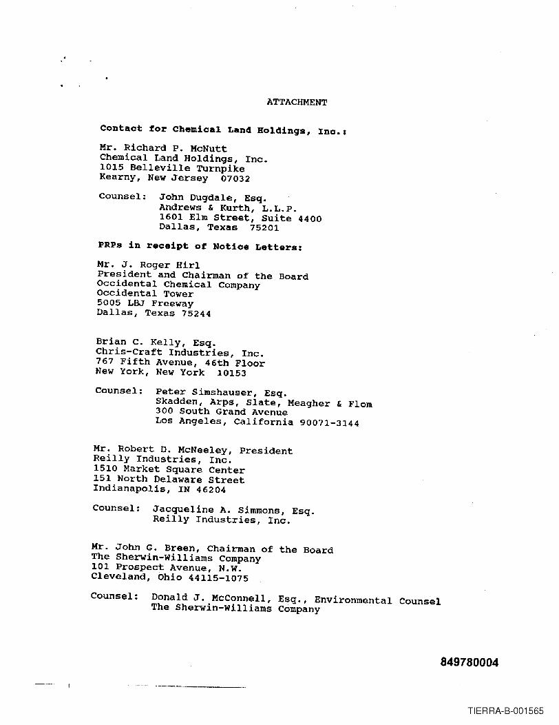
ATTACHMENT
Contact for Chemical Land Holdinqs, Inc.:Mr. Richard P. McNuttChemical Land Holdings, Inc.1015 Belleville TurnpikeKearny, New Jersey 07032
Counsel: John Dugdale, Esq.Andrews & Kurth, L.L.P.1601 Elm street, Suite 4400Dallas, Texas 75201
PRPs in receipt of Notice Letters:Mr. J. Roger HirlPresident and Chairman of the BoardOccidental Chemical CompanyOccidental Tower5005 LBJ FreewayDallas, Texas 75244
Brian C. Kelly, Esq.Chris-Craft Industries, Inc.767 Fifth Avenue, 46th FloorNew York, New York 10153
Counsel: Peter Simshauser, Esq.Skadden, Arps, Slate, Meagher & Flom300 South Grand AvenueLos Angeles, California 90071-3144
Mr. Robert D. McNeeley, PresidentReilly Industries, Inc.1510 Market Square Center151 North Delaware StreetIndianapolis, IN 46204
Counsel: Jacqueline A. Simmons, Esq.Reilly Industries, Inc.
Mr. John G. Breen, Chairman of the BoardThe Sherwin-Williams Company101 Prospect Avenue, N.W.Cleveland, Ohio 44115-1075
Counsel: Donald J. MCConnell, Esq., Environmental CounselThe Sherwin-Williams Company
849780004
TIERRA-B-001565

2
Mr. Robert L. Ball, PresidentAlcan Aluminum Corporation100 Erieview Plaza, 29th FloorCleveland, OH 44114
Counsel: Lawrence A. Salibra II, Esq., Senior CounselAlcan Aluminum Corporation6060 Parkland Blvd.Mayfield Hts., Ohio 44124
Mr. David J. D'Antoni, PresidentAshland Chemical CompanyP.O. Box 2219Columbus, OH 43216
Counsel: stephen W. Leermakers, Esq., Senior Litigation CounselAshland Chemical Company5200 Blazer ParkwayDUblin, Ohio 43017
Mr. Richard J. Mahoney, Chief ExecutiveMonsanto Company800 N. Lindbergh Blvd.st. Louis, MO 63167
Counsel: Peter H. Smith, Esq., Assistant Environmental CounselMonsanto Company
Mr. Maurice C. Workman, PresidentBenjamin Moore & Co.51 Chestnut Ridge RoadMontvale, New Jersey 07645
Counsel: John T. Rafferty, Esq., General CounselBenjamin Moore & Co.
Mr. Edgar s. Woolard, Jr., ChairmanE.!. du Pont de Nemours and Company1007 Market streetWilmington, Delaware 19898
Counsel: Bernard J. Reilly, Esq., Corporate CounselE.!. du Pont de Nemours and Company
849780005
TIERRA-B-001566

"
3
Mr. Joseph G. GabrielVice President of Operations360 North Pastoria Environmental Corporation1100 Ridgeway AvenueRochester, New York 14652-6280
Mr. George M. Fisher, PresidentEastman Kodak Company343 state streetRochester, New York 14650
Counsel: Elliott Stern, Esq., CounselEastman Kodak Company
PresidentBayer Corporation100 Bayer RoadPittsburgh, Pennsylvania 15205-9741Counsel: Gerard F. Hickel; Esq., Counsel
Bayer Corporation
Mr. Jean-pierre van Rooy, PresidentOtis Elevator CompanyNorth American Operations10 Farm Springs RoadFarmington, Connecticut 06032
Counsel: Joseph A. santos, Assistant Counselotis Elevator Company
Mr. Lawrence R. Codey, PresidentPublic Service Electric & Gas CompanyP.O. Box 570Newark, New Jersey 07101-0570
Counsel: Hugh J. Mahoney, Esq., General Environmental CounselPUblic Service Electric & Gas Company
849780006
TIERRA-B-001567

........ -----~- --- _ .._~._------ -..---+--.,
..A·Jv·
•E)& 13~.ArticIeArtk' :i8'jAddiddrreBisiSsedid'iitoii:": ---------pj~~iNt~~":J__:_==_=_=_
Mr. Lawrence R. Codey, President1Public Service Electric and Gas8 P.O. Box: 570
N~wark. New Jersey 07101-0570.
Domestic etum Receipt
-- -- -~--~----- -~--. --------~--_._----.
111111UNITED STATES POSTAl SERVICE
I,j,
F1rst-ClasiMallPostage & F••• PaidUSPSPermit No. 0.10
• Print your name, address, and ZIP Code In this box •
849780007
fIIl
.._-.
- U.S. EnY1ronmental ProL~"'_!OnAgencyRegIon U
OffIce of RegIona.1 CounselNew Jersey Superfund Branoh
290 Broadway. 17th FloorNew York. New York 10007-1866Attn: -,if!/)fA ~ a-hpr:e=Y
- --~----------
ITIERRA-B-001568

· . UNITED STATES ENVIRONMENTAL PROTECTION AGENCYREGION 2
290 BROADWAYNEW YORK, NY 10007-1866
8fP 1 5 2003
GENERAL NOTICE LETTERCERTIFIED MAIL-RETURN RECEIPT REQUESTED
Lawrence Codey, PresidentPSE&GCo.P.O. Box 570Newark, New Jersey 07101-0570
RE: Diamond Alkali Superfund SiteNotice of Potential Li~ilityfor_Response Actions in the Lower Passaic River, New Jersey
Dear Mr. Codey:
The United States Enviromnental Protection Agency ("EPA'') is charged with responding to therelease and/or threatened release of hazardous substances, pollutants, and contaminants into theenviromnent and with enforcement responsibilities under the Comprehensive EnvironmentalResponse, Compensation, and Liability Act of 1980, as amended ("CERCLA''), 42 U.S.C. §960l~~.You received a letter from EPA, dated July 1,1997, notifying PSE&G Co. ("PSE&G'') of itspotential liability relating to the Passaic River Study Area, which is part of the Diamond AlkaliSuperfund Site ("Site") located in Newark, New Jersey, pursuant to Section 107(a) ofCERCLA,42 U.S.C. §9607(a). Under CERCLA, potentially responsible parties ("PRPs'') include currentand past owners of a facility, as well as persons who arranged for the disposal or treatment ofhazardous substances at the Site, or the transport of hazardous substances to the Site.Accordingly, EPA is seeking your cooperation in an innovative approach to environmentalremediation and restoration activities for the Lower Passaic River.
EPA has documented the release or threatened release of hazardous substances, pollutants andcontaminants into the six-mile stretch of the river, known as the Passaic River Study Area, whichis part of the Site located in Newark, New Jersey. Based on the results of previous CERCLAremedial investigation activities and other environmental studies, including a reconnaissancestudy of the Passaic River conducted by the United States Army Corps of Engineers ("USACE"),EPA has further determined that contaminated sediments and other potential sources ofhazardous substances exist along the entire 17-mile tidal reach of the Lower Passaic River. Thus,EPA has decided to expand the Study to include the areal extent of contamination to whichhazardous substances from the six-mile stretch were transported; and those sources from whichhazardous substances outside the six-mile stretch have come to be located within the expandedStudy Area.
Intemet Address (URL). htlp:Jlwww.epa.govRecycled/Recyclable. Printlld with Vege"ble all B.Md Inks on Recycled Paper IMlnlmum 50% Postconsul1H!r content)
851870001
TIERRA-B-001569

In recognition of our complementary roles, EPA has fonned a partnership with USACE and theNew Jersey Department of Transportation-Office of Maritime Resources ("OMR") [''thegovernmental partnership"] to identify and to address water quality improvement, remediation,and restoration opportunities in the 17-mile Lower Passaic River. This governmental partnershipis consistent with a national Memorandum of Understanding ("MOU") executed on July 2, 2002between EPA and USACE. This MOU calls for the two agencies to cooperate, whereappropriate, on environmental remediation and restoration of degraded urban rivers and relatedresources. In agreeing to implement the MOU, the EPA and USACE will use their existingstatutory and regulatory authorities in a coordinated marmer. These authorities for EPA includeCERCLA, the Clean Water Act, and the Resource Conservation and Recovery Act. TheUSACE's authority stems from the Water Resources Development Act ("WRDA"). WRDAallows for the use of some federal funds to pay for a portion of the USACE's approved projectsrelated to ecosystem restoration.
For the first phase ofthe Lowe:r passaic River project, the gove111l11entalPa.rtne~are proceedingwith an integrated five- to.seven-year study to determine an appropriate remediation and .restoration plan for the river. The study will involve investigation of environmental impacts andpollution sources, as well as evaluation of alternative actions, leading to recommendations ofenvironmental remediation and restoration activities. This study is being conducted by EPAunder the authority of CERCLA and by USACE and OMR, as local sponsor, under WRDA.EPA, USACE, and OMR are coordinating with the New Jersey Department of EnvironmentalProtection and the Federal and State Natural Resource Trustee agencies. EPA, USACE, andOMR estimate that the study will cost approximately $20 million, with the WRDA and CERCLAshares being about $10 million each. EPA will be seeking its share of the costs of the study fromPRPs.
Based on infonnation that EPA evaluated during the.course of its investigation of the Site, EPAbelieves that hazardous substances were being released from the PSE&G facilities located at 155Raymond Boulevard in Newark, and 4111 Street in Harrison, New Jersey, into the Lower PassaicRiver. Hazardous substances, pollutants and contaminants released from the facility into theriver present a risk to the environment and the humans"who may ingest contaminated fish andshellfish. Therefore, PSE&G may be potentially liable for response costs which the governmentmay incur relating to the study of the Lower Passaic River. In addition, responsible parties maybe required to pay damages for injury to, destruction of, or loss of natural resources, including thecost of assessing such damages.
Enclosed is a list of the other PRPs who have received Notice letters. This list represents EPA'sfindings on the identities ofPRPs to date. We are continuing efforts to locate additional PRPswho have released hazardous substances, directly or indirectly, into the Passaic River. Inclusionon, or exclusion from, the list does not constitute a final determination by EPA concerning theliability of any party for the release or threat of release of hazardous substances at the Site. Beadvised that notice of your potential liability at the Site is being forwarded to all parties on thislist.
We request that you consider becoming a "cooperating party" for the Lower Passaic River
851870002
TIERRA-B-001570

Project. As a cooperating party, you, along with many other such parties, will be expected tofund EPA's share of the study costs. Upon completion of the study, it is expected that CERCLAand WRDA processes will be used to identify the required remediation and restoration programs,as well as the assi8nment of remediation and restoration costs. At this time, the commitments ofthe cooperating parties will apply only to the study. For those who choose not to cooperate, EPAmay apply the CERCLA enforcement process, pursuant to Sections 106 (a) and 107(a) ofCERCLA, 42 U.S.c. §9606(a) and §9607(a) and other laws.
Pursuant to CERCLA Section 113(k), ~PA must establish an administrative record that containsdocwnents that form the basis ofEPA's decision on the selection of a response action for a site.The administrative record files, which contain the documents related to the response actionselected for this Site are located at EPA's Region 2 office (290 Broadway, New York) on the 18'h
floor. You may call the Records Center at (212) 637-4308 to make an appointment to view theadministrative record for the Lower Passaic River Project.
-. -EPA'will be hofdlng a meeting with all PRPS()fi October 29,-2003 at 10:00 AM in ConferenceRoom 27A at the Region 2 office. At that meeting, EPA will provide information about theactions taken to date in the Lower Passaic River, as well as plans for future activities. After thepresentation, PRPs wi1l be given the opportunity to caucus, and EPA will return to answer anyquestions that might be generated during the private session. Please be advised that due toincreased security measures, all visitors need to be registered with the security desk in the lobbyin order to gain entry to the office. In order to ensure a smooth arrival, you will need to provideEPA with a list of attendees no later than October 15, 2003.
EPA recommends that the cooperating parties select a steering committee to represent thegroup's interest as soon as possible, since EPA expects a funding commitment for the financingof the CERCLA share ofthe $20 million study by mid-November 2003. If you wish to discussthis further, please contact Ms. Alice Yeh, Remedial Project Manager, at (212) 637-4427 or Ms.Kedari Reddy, Assistant Regional Counsel, at (212) 637-3106. Please note that allcommunications from attorneys should be directed to Ms. Reddy.
Sincerely yours,
George PavIou, DirectorEmergency and Remedial Response Division
Enclosure
cc: Hugh Mahoney, Esq.PSE&GCo.
851870003
TIERRA-B-001571

1arm0EP~1 c
'~OJrtt~
~ c;J . ft!2.-1f 'RECtD .v --KLJJl.-I---7~~f-r-~~,
__ hllpOlMllon - ~:..- .--' ,.~,,:,"'-'-'.'_"~-:-.....,..~--:~ .......~. ........ ;t' ,
.- '.:':- . '. -', ".~'- - ."; ..... ~-.'~:~..
IDENTITY OF SUBSTANCE(S} SPILLED, r;t~ED. ETC.:Nam. of Substance(.tlGu. Uquid. Solid); __ +hb~"---r---r-.L.JIvltua"'~Q~'-:::.....!.."Le~ _AnDIn~~ L~_'IC. _ .......1YPe III ~: 'lenni1'Wlld __ ConIInuaua
__ St~ __u.-
--~'__ InIannIIIIlI
- 'IDENT DESCftIPTION:__ Fire __ ExpQion __ Alr ReI
-- Odcl<w __ s.w.g. __ NJPOES
_ Equip Stan4JplShutOOwn. Equip fWllUl*II. ... --' _
__ Other (apec;lyl ~ _
-- """ -- ~ -- ~__ WikIItI __ ' /IIegIII Oumping __ DM.__ NoIM
PublIc Expoaurw
Rre 0epu1menI • 8cIfle
f'I:llIca .. ScletM---~~
o-n--# f /.1"20 (T....0-"_ J fTJIIl
0-1' I ~
I IS .1" (TAlI
L.oe-' ..... " _ Pt'OIW _
-._~--,--~ ...!.~/iL.m~
850240017
.' " -:... ~.-.' ..,: ~..-..-:"-
TIERRA-B-001572

-
-
.1:::.· .;:' (~.:;-'-_~-r:INCIDENT 0EICM'Tl00I' . /',_.... --~ _NIAll ~-- OdIn __ ..... _ M.PClE8 _ ....
- ~~~~ .._--------------------_ c.. ........_-= _
~..:- ••::: ~~ /' .-/ =M=..::--1M -U!'A~l"" ::'00--._ ....... ====::::1::===:-l..-.,... _ p _ Z _~C.--.A:a-_ ......
nan.. ... -~~~~~~=-:~~~~~~~~:311!=..4~::::.--
-~ ..... ~u11Lzs"'~U
-
---. _.-_ ....- ...... - ... ~_a.-
_.- .......
..... 0........- ...... y........... If
.0.. _l".
DnlOAU NOiWC ~ ..
'lUll' 111k~L~~:~ t --~,4J.':. ._._-"-- ':"·...LilJ.L ~ ~_, J:z~ fI*l~. - ._.__.._--_..._---_._. , ------..- '--'-' .. "-- ---._ CliMo"'-.___ ,..~. - - /C - .. -"'- ........ ,. • , ,....... 6.:_·~'.·/! "f,'.~':~-~:-.- -. ,:J.::' _ ~1 :':',.~. !~:..-.-. ""'"
850240018
TIERRA-B-001573

-
) C:New Jersey Department of Environmental Protection
COMMUNICATIONS CENTER NOTIFICATION REPORTReceived: 1/28/91 TO Loq I 1170Operator:RICH Case' 91-1-28-0829_00-------------------------------------------------------------------------------Reported ay
PETER VIVIRITOStreet Address
71 EDISON TERR
Notification Type: CitizenAffiliation
CITIZENMunicipality
SPARTA
Phone201-729-2686
StateNJ- - - - - - ------ --------Incident Location: Other
Site IN RIVER SOUTH OF FIREBOAT PhoneStreet Address Municipality
DOCK-TO PSE&G PLT NEWARKLocation Type Industrial Incident Date
CountyESSEX1/28/91
StateNJ
Time 0745--------------------~--------------------~-------------------------------------Substance Released OIL SHEENAmount Released {Known )UNKNOWN
ID:Known State Liquid CAS' Release Is ContinuousAdditional SubstancesSubstance Contained? N Hazardous Material? Y TePA? N A310 Letter? Y
(OMU CODE: 0714 REF CODEI 001--------------------~----------------------------------------------------------Incident De$cription spill
Injuries? N Public Evac? N Facility Evec? N Public Exposure? NPolice On Scene? N Firemen On Scene? N DEP Requested? Y Wind Sp/Dir
Contamination Of Water Receiving Water PASSAIC RIVERStatus At Scene SLICK MOVING DOWN WITH THE TIDE _ SOURCE UNKNOWN_ CONSTANT
-------------------------------------------------------------------------------Responsible Party UnKnownParty PhoneContact Title
Street Address Municipality County State
NAMENJSP : OEMMUNJC: NEWARK CITYOTHER:
OFFICIALS NOTIFIEDTITLE PHONE DATE TIME
609-882-2000 1/28OPER 41 201-733-7400 1/28 0840
-----------~------------------~---------~--------------------------------------Name1. MATT GARAMONE2.3.
AffiliationDEQ ER1
Method Date Time TIMOffice,Faxed 1/28 0838 T
==;===:~=~=======:=======::=::======;~===================-:=================:==
850240019
TIERRA-B-001574