Embed Size (px)
Citation preview
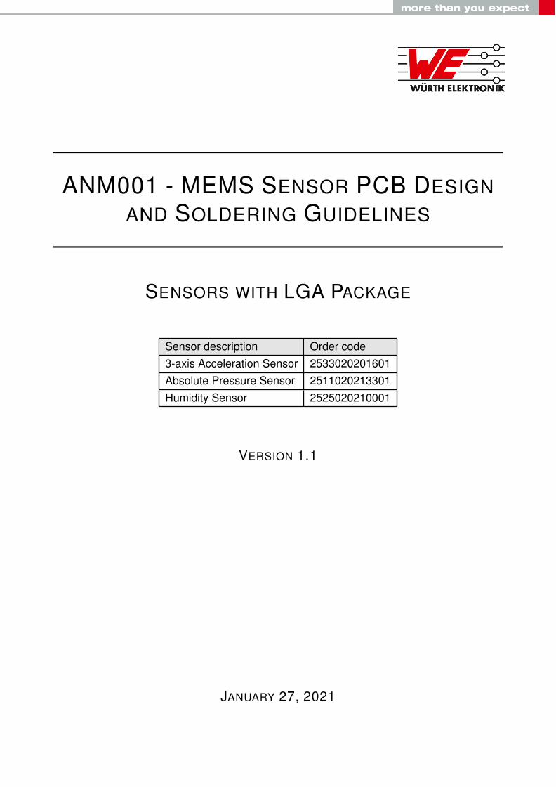
ANM001 - MEMS SENSOR PCB DESIGNAND SOLDERING GUIDELINES
SENSORS WITH LGA PACKAGE
Sensor description Order code3-axis Acceleration Sensor 2533020201601Absolute Pressure Sensor 2511020213301Humidity Sensor 2525020210001
VERSION 1.1
JANUARY 27, 2021
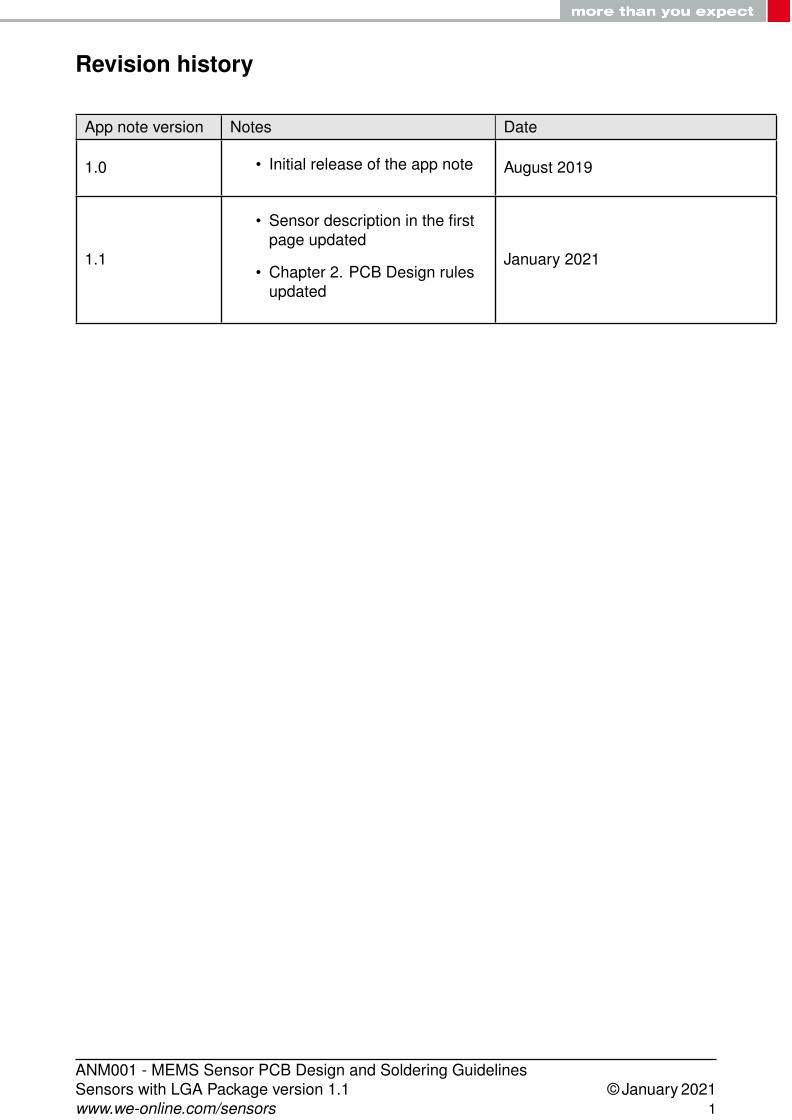
Revision history
App note version Notes Date
1.0 • Initial release of the app note August 2019
1.1
• Sensor description in the firstpage updated
• Chapter 2. PCB Design rulesupdated
January 2021
ANM001 - MEMS Sensor PCB Design and Soldering GuidelinesSensors with LGA Package version 1.1 © January 2021www.we-online.com/sensors 1
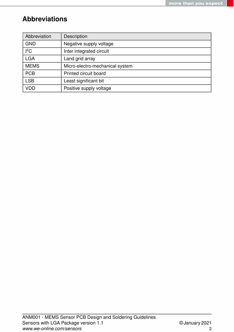
Abbreviations
Abbreviation Description
GND Negative supply voltage
I2C Inter integrated circuit
LGA Land grid array
MEMS Micro-electro-mechanical system
PCB Printed circuit board
LSB Least significant bit
VDD Positive supply voltage
ANM001 - MEMS Sensor PCB Design and Soldering GuidelinesSensors with LGA Package version 1.1 © January 2021www.we-online.com/sensors 2
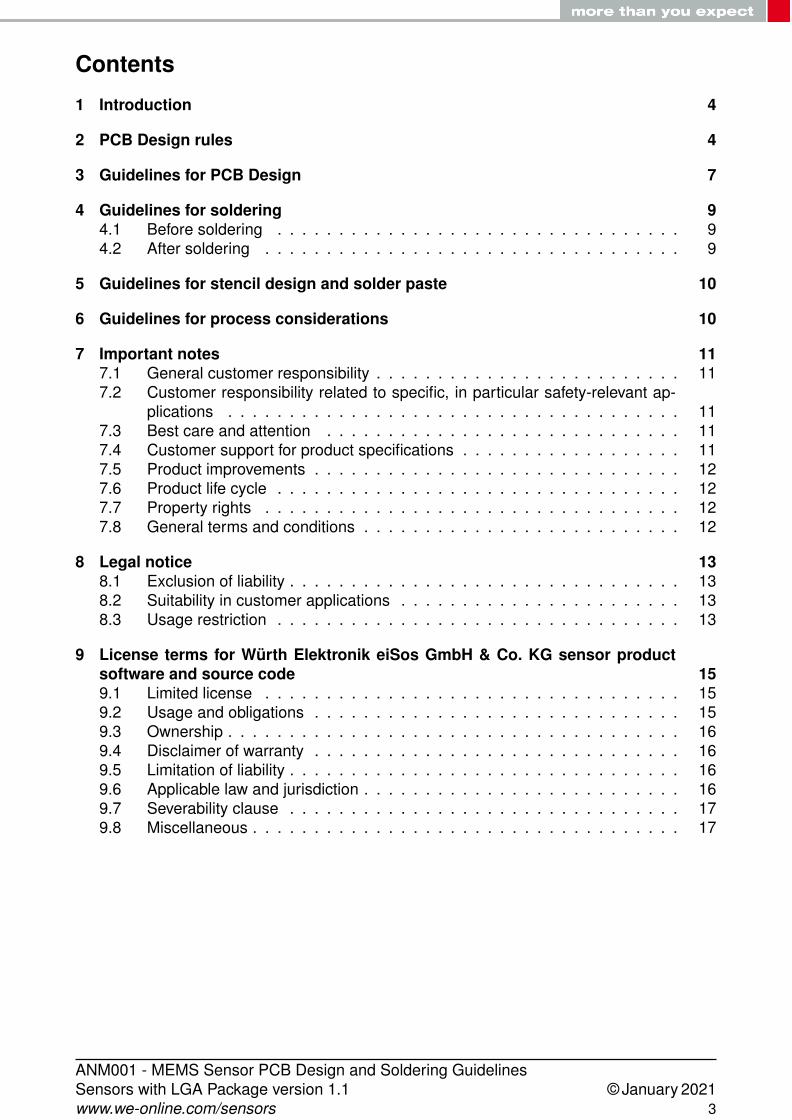
Contents
1 Introduction 4
2 PCB Design rules 4
3 Guidelines for PCB Design 7
4 Guidelines for soldering 94.1 Before soldering . . . . . . . . . . . . . . . . . . . . . . . . . . . . . . . . . 94.2 After soldering . . . . . . . . . . . . . . . . . . . . . . . . . . . . . . . . . . 9
5 Guidelines for stencil design and solder paste 10
6 Guidelines for process considerations 10
7 Important notes 117.1 General customer responsibility . . . . . . . . . . . . . . . . . . . . . . . . . 117.2 Customer responsibility related to specific, in particular safety-relevant ap-
plications . . . . . . . . . . . . . . . . . . . . . . . . . . . . . . . . . . . . . 117.3 Best care and attention . . . . . . . . . . . . . . . . . . . . . . . . . . . . . 117.4 Customer support for product specifications . . . . . . . . . . . . . . . . . . 117.5 Product improvements . . . . . . . . . . . . . . . . . . . . . . . . . . . . . . 127.6 Product life cycle . . . . . . . . . . . . . . . . . . . . . . . . . . . . . . . . . 127.7 Property rights . . . . . . . . . . . . . . . . . . . . . . . . . . . . . . . . . . 127.8 General terms and conditions . . . . . . . . . . . . . . . . . . . . . . . . . . 12
8 Legal notice 138.1 Exclusion of liability . . . . . . . . . . . . . . . . . . . . . . . . . . . . . . . . 138.2 Suitability in customer applications . . . . . . . . . . . . . . . . . . . . . . . 138.3 Usage restriction . . . . . . . . . . . . . . . . . . . . . . . . . . . . . . . . . 13
9 License terms for Würth Elektronik eiSos GmbH & Co. KG sensor productsoftware and source code 159.1 Limited license . . . . . . . . . . . . . . . . . . . . . . . . . . . . . . . . . . 159.2 Usage and obligations . . . . . . . . . . . . . . . . . . . . . . . . . . . . . . 159.3 Ownership . . . . . . . . . . . . . . . . . . . . . . . . . . . . . . . . . . . . . 169.4 Disclaimer of warranty . . . . . . . . . . . . . . . . . . . . . . . . . . . . . . 169.5 Limitation of liability . . . . . . . . . . . . . . . . . . . . . . . . . . . . . . . . 169.6 Applicable law and jurisdiction . . . . . . . . . . . . . . . . . . . . . . . . . . 169.7 Severability clause . . . . . . . . . . . . . . . . . . . . . . . . . . . . . . . . 179.8 Miscellaneous . . . . . . . . . . . . . . . . . . . . . . . . . . . . . . . . . . . 17
ANM001 - MEMS Sensor PCB Design and Soldering GuidelinesSensors with LGA Package version 1.1 © January 2021www.we-online.com/sensors 3
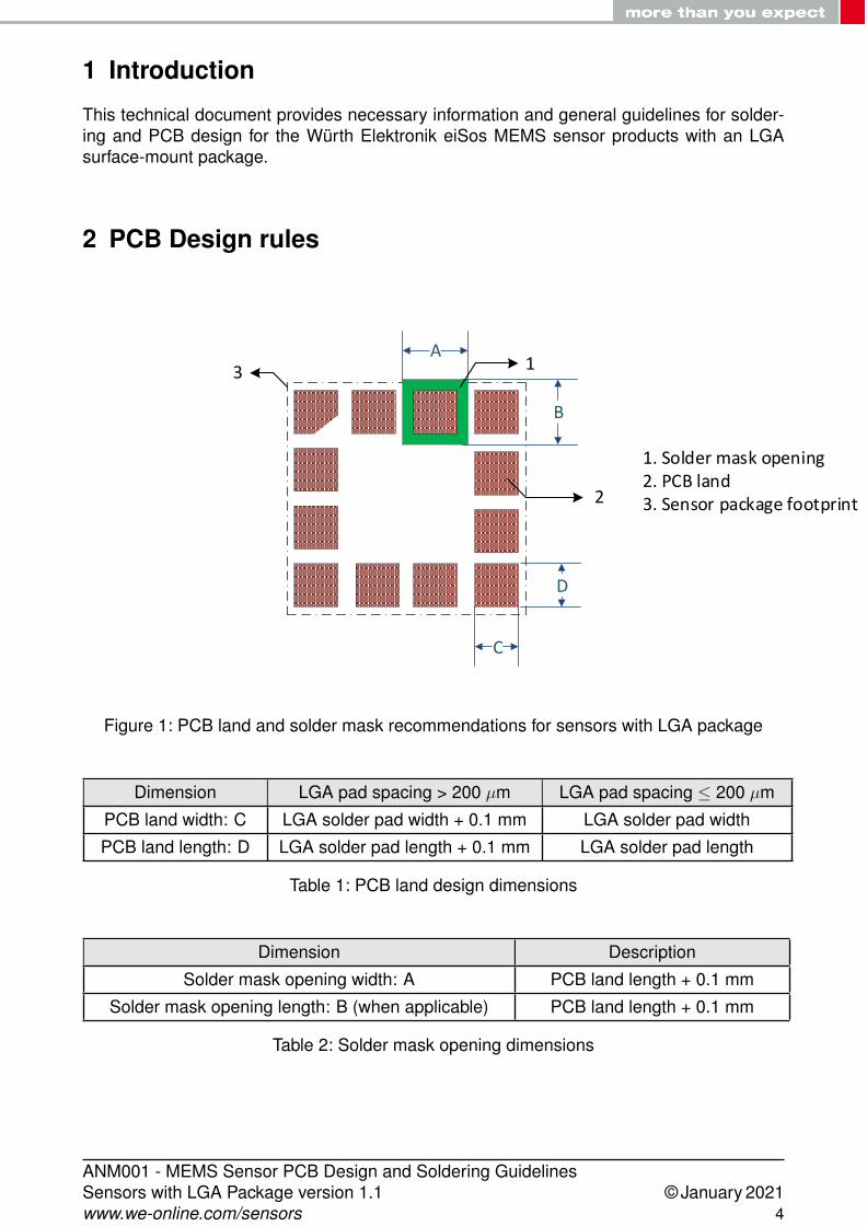
1 Introduction
This technical document provides necessary information and general guidelines for solder-ing and PCB design for the Würth Elektronik eiSos MEMS sensor products with an LGAsurface-mount package.
2 PCB Design rules
A
B
C
D
1
2
3
1. Solder mask opening2. PCB land3. Sensor package footprint
Figure 1: PCB land and solder mask recommendations for sensors with LGA package
Dimension LGA pad spacing > 200 µm LGA pad spacing ≤ 200 µm
PCB land width: C LGA solder pad width + 0.1 mm LGA solder pad width
PCB land length: D LGA solder pad length + 0.1 mm LGA solder pad length
Table 1: PCB land design dimensions
Dimension Description
Solder mask opening width: A PCB land length + 0.1 mm
Solder mask opening length: B (when applicable) PCB land length + 0.1 mm
Table 2: Solder mask opening dimensions
ANM001 - MEMS Sensor PCB Design and Soldering GuidelinesSensors with LGA Package version 1.1 © January 2021www.we-online.com/sensors 4
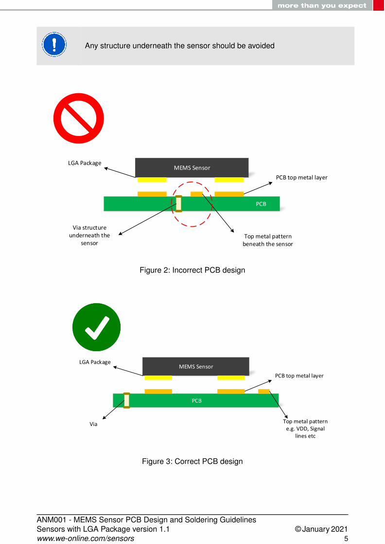
Any structure underneath the sensor should be avoided
PCB
MEMS Sensor
Via structure underneath the
sensor
PCB top metal layer
Top metal pattern beneath the sensor
LGA Package
Figure 2: Incorrect PCB design
PCB
MEMS Sensor
Via
PCB top metal layer
Top metal patterne.g. VDD, Signal
lines etc
LGA Package
Figure 3: Correct PCB design
ANM001 - MEMS Sensor PCB Design and Soldering GuidelinesSensors with LGA Package version 1.1 © January 2021www.we-online.com/sensors 5
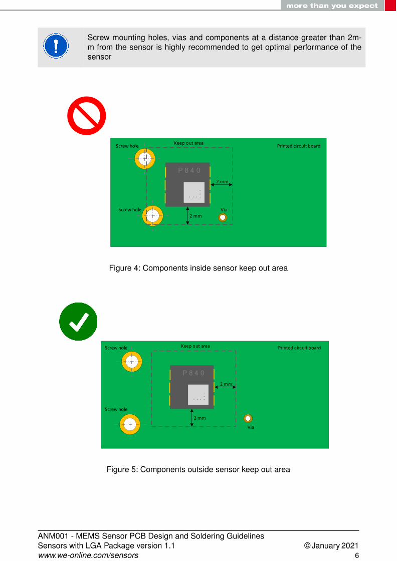
Screw mounting holes, vias and components at a distance greater than 2m-m from the sensor is highly recommended to get optimal performance of thesensor
P 8 4 0
. . .. . .
2 mm
2 mm
Screw hole
Via
Keep out areaPrinted circuit board
Screw hole
Figure 4: Components inside sensor keep out area
P 8 4 0
. . .. . .
2 mm
2 mm
Screw hole
Via
Keep out area Printed circuit boardScrew hole
Figure 5: Components outside sensor keep out area
ANM001 - MEMS Sensor PCB Design and Soldering GuidelinesSensors with LGA Package version 1.1 © January 2021www.we-online.com/sensors 6
3 Guidelines for PCB Design
• The solder mask opening external to the PCB land is highly recommended. Pleaserefer to figure 1.
• It is recommended to define a keep-out area for the sensor. Any structure underneaththe sensor should be avoided.
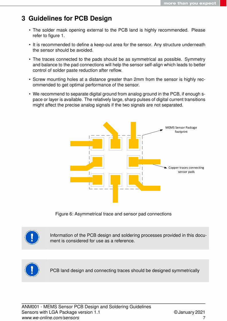
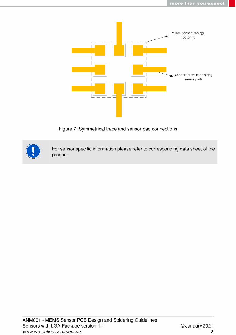
• The traces connected to the pads should be as symmetrical as possible. Symmetryand balance to the pad connections will help the sensor self-align which leads to bettercontrol of solder paste reduction after reflow.
• Screw mounting holes at a distance greater than 2mm from the sensor is highly rec-ommended to get optimal performance of the sensor.
• We recommend to separate digital ground from analog ground in the PCB, if enough s-pace or layer is available. The relatively large, sharp pulses of digital current transitionsmight affect the precise analog signals if the two signals are not separated.
MEMS Sensor Package footprint
Copper traces connecting sensor pads
v
Figure 6: Asymmetrical trace and sensor pad connections
Information of the PCB design and soldering processes provided in this docu-ment is considered for use as a reference.
PCB land design and connecting traces should be designed symmetrically
ANM001 - MEMS Sensor PCB Design and Soldering GuidelinesSensors with LGA Package version 1.1 © January 2021www.we-online.com/sensors 7
MEMS Sensor Package footprint
Copper traces connecting sensor pads
V
Figure 7: Symmetrical trace and sensor pad connections
For sensor specific information please refer to corresponding data sheet of theproduct.
ANM001 - MEMS Sensor PCB Design and Soldering GuidelinesSensors with LGA Package version 1.1 © January 2021www.we-online.com/sensors 8
4 Guidelines for soldering
The following soldering guidelines should be taken into consideration for a common PCBdesign and industrial practices.
4.1 Before soldering
• Routing traces and vias below the sensor should be avoided. The active signals thatare routed under may interfere with the MEMS sensor, which will affect the sensorperformance.
• It is not necessary to have large traces on VDD/GND line, as the power consumptionof the MEMS sensors are very low.
• For best performance of the sensor, design a ground plane under the sensor in orderto reduce the PCB signal noise from the board.
• The placement of the MEMS sensor on the PCB should avoid locations in close prox-imity to heat sources e.g. microprocessors, batteries, graphic controllers etc.
• Push-buttons, screws and PCB anchor points can produce mechanical stress onto thePCB, hence the sensor placement close to these components should be avoided.
• PCB bending will induce mechanical stress to the sensor therewith influence the sen-sor performance.
4.2 After soldering
• In general, high-amplitude resonant vibrations of the PCB should be avoided. It couldpossibly damage the MEMS structure.
• The thickness of solder paster must be uniform to reduce the inconsistent stress onthe sensor.
• Solder paste must be as thick as possible to reduce the decoupling stress and to avoidthe PCB solder mask touching the device package.
ANM001 - MEMS Sensor PCB Design and Soldering GuidelinesSensors with LGA Package version 1.1 © January 2021www.we-online.com/sensors 9

5 Guidelines for stencil design and solder paste
For proper mounting process of the MEMS sensor, thickness and soldering paste patternare very important.
• Stencil thickness of 90 - 150 µm (3.5 - 6 mils) is recommended for screen printing.
• Stainless steel stencils are recommended for solder paste application.
• The signal pad openings of the stencil should be between 70% and 90% of the PCBpad area.
• It is recommended that for better solder paste release, the aperture walls should betrapezoidal and the corners rounded.
• The stencil and printed circuit assembly should be aligned to within 25 µm (1 mil)before applying the solder paste.
6 Guidelines for process considerations
• To reduce the residual stress on the components, the recommended ramp-down tem-perature slope should not exceed -3°C/s.
• LGA packages show metal traces on the side of the package, hence no solder materialreflow on the side of the package is allowed.
• The final volume of the solder paste applied to a single PCB land should be less than20% of the volume of the solder paste of all pads of one device.
• It is not possible to define a specific soldering profile only for the sensors. The sol-dering profile depends on the number, size and placement of the components in theapplication board.
• Customer should use a time and temperature reflow profile based on PCB design andmanufacturing knowledge.
• No-clean solder paste is recommended for assembly of the MEMS sensor to preventfurther cleaning steps.
• Sensor with opening surface on top should be handled carefully. Do not pick the com-ponent with vacuum tools which make direct contact with the opening of the sensor.
It is recommended to use a standard pick and place process and equipment.Do not use the hand soldering process.
ANM001 - MEMS Sensor PCB Design and Soldering GuidelinesSensors with LGA Package version 1.1 © January 2021www.we-online.com/sensors 10
7 Important notes
The following conditions apply to all goods within the sensors product range of Würth Elek-tronik eiSos GmbH & Co. KG:
7.1 General customer responsibility
Some goods within the product range of Würth Elektronik eiSos GmbH & Co. KG containstatements regarding general suitability for certain application areas. These statementsabout suitability are based on our knowledge and experience of typical requirements con-cerning the areas, serve as general guidance and cannot be estimated as binding statementsabout the suitability for a customer application. The responsibility for the applicability and usein a particular customer design is always solely within the authority of the customer. Due tothis fact, it is up to the customer to evaluate, where appropriate to investigate and to decidewhether the device with the specific product characteristics described in the product speci-fication is valid and suitable for the respective customer application or not. Accordingly, thecustomer is cautioned to verify that the documentation is current before placing orders.
7.2 Customer responsibility related to specific, in particularsafety-relevant applications
It has to be clearly pointed out that the possibility of a malfunction of electronic componentsor failure before the end of the usual lifetime cannot be completely eliminated in the currentstate of the art, even if the products are operated within the range of the specifications.The same statement is valid for all software and software parts contained in or used withor for products in the sensor product range of Würth Elektronik eiSos GmbH & Co. KG.In certain customer applications requiring a high level of safety and especially in customerapplications in which the malfunction or failure of an electronic component could endangerhuman life or health, it must be ensured by most advanced technological aid of suitabledesign of the customer application that no injury or damage is caused to third parties in theevent of malfunction or failure of an electronic component.
7.3 Best care and attention
Any product-specific data sheets, manuals, application notes, PCN’s, warnings and cau-tions must be strictly observed in the most recent versions and matching to the productsrevisions. This documents can be downloaded from the product specific sections on thewireless connectivity and sensors homepage.
7.4 Customer support for product specifications
Some products within the product range may contain substances, which are subject to re-strictions in certain jurisdictions in order to serve specific technical requirements. Necessaryinformation is available on request. In this case, the field sales engineer or the internal salesperson in charge should be contacted who will be happy to support in this matter.
ANM001 - MEMS Sensor PCB Design and Soldering GuidelinesSensors with LGA Package version 1.1 © January 2021www.we-online.com/sensors 11

7.5 Product improvements
Due to constant product improvement, product specifications may change from time to time.As a standard reporting procedure of the Product Change Notification (PCN) according tothe JEDEC-Standard, we inform about major changes. In case of further queries regardingthe PCN, the field sales engineer, the internal sales person or the technical support teamin charge should be contacted. The basic responsibility of the customer as per section 7.1
and 7.2 remains unaffected.The sensor driver software ¨Sensor SDK¨ and it’s source codes are not subject to the Prod-uct Change Notification information process.
7.6 Product life cycle
Due to technical progress and economical evaluation we also reserve the right to discontin-ue production and delivery of products. As a standard reporting procedure of the ProductTermination Notification (PTN) according to the JEDEC-Standard we will inform at an earlystage about inevitable product discontinuance. According to this, we cannot ensure that allproducts within our product range will always be available. Therefore, it needs to be verifiedwith the field sales engineer or the internal sales person in charge about the current productavailability expectancy before or when the product for application design-in disposal is con-sidered. The approach named above does not apply in the case of individual agreementsdeviating from the foregoing for customer-specific products.
7.7 Property rights
All the rights for contractual products produced by Würth Elektronik eiSos GmbH & Co. KGon the basis of ideas, development contracts as well as models or templates that are subjectto copyright, patent or commercial protection supplied to the customer will remain with WürthElektronik eiSos GmbH & Co. KG. Würth Elektronik eiSos GmbH & Co. KG does not warrantor represent that any license, either expressed or implied, is granted under any patent right,copyright, mask work right, or other intellectual property right relating to any combination,application, or process in which Würth Elektronik eiSos GmbH & Co. KG components orservices are used.
7.8 General terms and conditions
Unless otherwise agreed in individual contracts, all orders are subject to the current ver-sion of the "General Terms and Conditions of Würth Elektronik eiSos Group", last versionavailable at www.we-online.com.
ANM001 - MEMS Sensor PCB Design and Soldering GuidelinesSensors with LGA Package version 1.1 © January 2021www.we-online.com/sensors 12

8 Legal notice
8.1 Exclusion of liability
Würth Elektronik eiSos GmbH & Co. KG considers the information in this document to becorrect at the time of publication. However, Würth Elektronik eiSos GmbH & Co. KG re-serves the right to modify the information such as technical specifications or functions ofits products or discontinue the production of these products or the support of one of theseproducts without any written announcement or notification to customers. The customer mustmake sure that the information used corresponds to the latest published information. WürthElektronik eiSos GmbH & Co. KG does not assume any liability for the use of its products.Würth Elektronik eiSos GmbH & Co. KG does not grant licenses for its patent rights or forany other of its intellectual property rights or third-party rights.
Notwithstanding anything above, Würth Elektronik eiSos GmbH & Co. KG makes no repre-sentations and/or warranties of any kind for the provided information related to their accuracy,correctness, completeness, usage of the products and/or usability for customer applications.Information published by Würth Elektronik eiSos GmbH & Co. KG regarding third-party prod-ucts or services does not constitute a license to use such products or services or a warrantyor endorsement thereof.
8.2 Suitability in customer applications
The customer bears the responsibility for compliance of systems or units, in which WürthElektronik eiSos GmbH & Co. KG products are integrated, with applicable legal regulations.Customer acknowledges and agrees that it is solely responsible for compliance with all le-gal, regulatory and safety-related requirements concerning its products, and any use ofWürth Elektronik eiSos GmbH & Co. KG components in its applications, notwithstandingany applications-related in-formation or support that may be provided by Würth Elektron-ik eiSos GmbH & Co. KG. Customer represents and agrees that it has all the necessaryexpertise to create and implement safeguards which anticipate dangerous consequences offailures, monitor failures and their consequences lessen the likelihood of failures that mightcause harm and take appropriate remedial actions. The customer will fully indemnify WürthElektronik eiSos GmbH & Co. KG and its representatives against any damages arising outof the use of any Würth Elektronik eiSos GmbH & Co. KG components in safety-criticalapplications.
8.3 Usage restriction
Würth Elektronik eiSos GmbH & Co. KG products have been designed and developed forusage in general electronic equipment only. This product is not authorized for use in equip-ment where a higher safety standard and reliability standard is especially required or wherea failure of the product is reasonably expected to cause severe personal injury or death,unless the parties have executed an agreement specifically governing such use. Moreover,Würth Elektronik eiSos GmbH & Co. KG products are neither designed nor intended for usein areas such as military, aerospace, aviation, nuclear control, submarine, transportation(automotive control, train control, ship control), transportation signal, disaster prevention,medical, public information network etc. Würth Elektronik eiSos GmbH & Co. KG must be
ANM001 - MEMS Sensor PCB Design and Soldering GuidelinesSensors with LGA Package version 1.1 © January 2021www.we-online.com/sensors 13
informed about the intent of such usage before the design-in stage. In addition, sufficientreliability evaluation checks for safety must be performed on every electronic component,which is used in electrical circuits that require high safety and reliability function or perfor-mance. By using Würth Elektronik eiSos GmbH & Co. KG products, the customer agrees tothese terms and conditions.
ANM001 - MEMS Sensor PCB Design and Soldering GuidelinesSensors with LGA Package version 1.1 © January 2021www.we-online.com/sensors 14

9 License terms for Würth Elektronik eiSosGmbH & Co. KG sensor product software and sourcecode
This License terms will take effect upon the purchase and usage of the Würth ElektronikeiSos GmbH & Co. KG sensor products. You hereby agree that this license terms are appli-cable to the product and the incorporated software, firmware and source codes (collectively,"Software") made available by Würth Elektronik eiSos in any form, including but not limitedto binary, executable or source code form.The software included in any Würth Elektronik eiSos sensor product is purchased to you onthe condition that you accept the terms and conditions of this license terms. You agree tocomply with all provisions under this license terms.
9.1 Limited license
Würth Elektronik eiSos hereby grants you a limited, non-exclusive, non-transferable androyalty-free license to use the software and under the conditions that will be set forth in thislicense terms. You are free to use the provided software only in connection with one of theproducts from Würth Elektronik eiSos to the extent described in this license terms.You are entitled to change or alter the source code for the sole purpose of creating an ap-plication embedding the Würth Elektronik eiSos sensor product. The transfer of the sourcecode to third parties is allowed to the sole extent that the source code is used by such thirdparties in connection with our product or another hardware provided by Würth ElektronikeiSos under strict adherence of this license terms. Würth Elektronik eiSos will not assumeany liability for the usage of the incorporated software and the source code.You are not entitled to transfer the source code in any form to third parties without prior writ-ten consent of Würth Elektronik eiSos.You are not allowed to reproduce, translate, reverse engineer, decompile, disassemble orcreate derivative works of the incorporated software and the source code in whole or in part.No more extensive rights to use and exploit the products are granted to you.
9.2 Usage and obligations
The responsibility for the applicability and use of the Würth Elektronik eiSos sensor productwith the incorporated software in a particular customer design is always solely within theauthority of the customer. Due to this fact, it is up to you to evaluate and investigate, whereappropriate, and to decide whether the device with the specific product characteristics de-scribed in the product specification is valid and suitable for your respective application ornot.You are responsible for using the Würth Elektronik eiSos sensor product with the incorporat-ed software in compliance with all applicable product liability and product safety laws. Youacknowledge to minimize the risk of loss and harm to individuals and bear the risk for failureleading to personal injury or death due to your usage of the product.Würth Elektronik eiSos’ products are not authorized for use in safety-critical applications,or where a failure of the product is reasonably expected to cause severe personal injuryor death. Moreover, Würth Elektronik eiSos’ products are neither designed nor intended for
ANM001 - MEMS Sensor PCB Design and Soldering GuidelinesSensors with LGA Package version 1.1 © January 2021www.we-online.com/sensors 15
use in areas such as military, aerospace, aviation, nuclear control, submarine, transportation(automotive control, train control, ship control), transportation signal, disaster prevention,medical, public information network etc. You shall inform Würth Elektronik eiSos about theintent of such usage before design-in stage. In certain customer applications requiring a veryhigh level of safety and in which the malfunction or failure of an electronic component couldendanger human life or health, you must ensure to have all necessary expertise in the safetyand regulatory ramifications of your applications. You acknowledge and agree that you aresolely responsible for all legal, regulatory and safety-related requirements concerning yourproducts and any use of Würth Elektronik eiSos’ products in such safety-critical application-s, notwithstanding any applications-related information or support that may be provided byWürth Elektronik eiSos. YOU SHALL INDEMNIFY WÜRTH ELEKTRONIK EISOS AGAINSTANY DAMAGES ARISING OUT OF THE USE OF WÜRTH ELEKTRONIK EISOS’ PROD-UCTS IN SUCH SAFETY-CRITICAL APPLICATIONS.
9.3 Ownership
The incorporated Software created by Würth Elektronik eiSos is and will remain the exclusiveproperty of Würth Elektronik eiSos.
9.4 Disclaimer of warranty
THE SOFTWARE AND IT’S SOURCE CODE IS PROVIDED "AS IS". YOU ACKNOWL-EDGE THAT WÜRTH ELEKTRONIK EISOS MAKES NO REPRESENTATIONS AND WAR-RANTIES OF ANY KIND RELATED TO, BUT NOT LIMITED TO THE NON-INFRINGEMENTOF THIRD PARTIES’ INTELLECTUAL PROPERTY RIGHTS OR THE MERCHANTABILI-TY OR FITNESS FOR YOUR INTENDED PURPOSE OR USAGE. WÜRTH ELEKTRONIKEISOS DOES NOT WARRANT OR REPRESENT THAT ANY LICENSE, EITHER EXPRESSOR IMPLIED, IS GRANTED UNDER ANY PATENT RIGHT, COPYRIGHT, MASK WORKRIGHT, OR OTHER INTELLECTUAL PROPERTY RIGHT RELATING TO ANY COMBINA-TION, MACHINE, OR PROCESS IN WHICH THE WÜRTH ELEKTRONIK EISOS’ PROD-UCT WITH THE INCORPORATED SOFTWARE IS USED. INFORMATION PUBLISHED BYWÜRTH ELEKTRONIK EISOS REGARDING THIRD-PARTY PRODUCTS OR SERVICESDOES NOT CONSTITUTE A LICENSE FROM WÜRTH ELEKTRONIK EISOS TO USESUCH PRODUCTS OR SERVICES OR A WARRANTY OR ENDORSEMENT THEREOF.
9.5 Limitation of liability
Any liability not expressly provided by Würth Elektronik eiSos shall be disclaimed.You agree to hold us harmless from any third-party claims related to your usage of the WürthElektronik eiSos’ products with the incorporated software and source code. Würth ElektronikeiSos disclaims any liability for any alteration, development created by you or your customersas well as for any combination with other products.
9.6 Applicable law and jurisdiction
Applicable law to this license terms shall be the laws of the Federal Republic of Germany.Any dispute, claim or controversy arising out of or relating to this license terms shall be
ANM001 - MEMS Sensor PCB Design and Soldering GuidelinesSensors with LGA Package version 1.1 © January 2021www.we-online.com/sensors 16
resolved and finally settled by the court competent for the location of Würth Elektronik eiSosregistered office.
9.7 Severability clause
If a provision of this license terms are or becomes invalid, unenforceable or null and void,this shall not affect the remaining provisions of the terms. The parties shall replace any suchprovisions with new valid provisions that most closely approximate the purpose of the terms.
9.8 Miscellaneous
Würth Elektronik eiSos reserves the right at any time to change this terms at its own discre-tion. It is your responsibility to check at Würth Elektronik eiSos homepage for any updates.Your continued usage of the products will be deemed as the acceptance of the change.We recommend you to be updated about the status of new software, which is available onour website or in our data sheet, and to implement new software in your device where ap-propriate.By ordering a sensor product, you accept this license terms in all terms.
ANM001 - MEMS Sensor PCB Design and Soldering GuidelinesSensors with LGA Package version 1.1 © January 2021www.we-online.com/sensors 17
List of Figures
1 PCB land and solder mask recommendations for sensors with LGA package 42 Incorrect PCB design . . . . . . . . . . . . . . . . . . . . . . . . . . . . . . . 53 Correct PCB design . . . . . . . . . . . . . . . . . . . . . . . . . . . . . . . . 54 Components inside sensor keep out area . . . . . . . . . . . . . . . . . . . . 65 Components outside sensor keep out area . . . . . . . . . . . . . . . . . . . 66 Asymmetrical trace and sensor pad connections . . . . . . . . . . . . . . . . 77 Symmetrical trace and sensor pad connections . . . . . . . . . . . . . . . . . 8
List of Tables
1 PCB land design dimensions . . . . . . . . . . . . . . . . . . . . . . . . . . . 42 Solder mask opening dimensions . . . . . . . . . . . . . . . . . . . . . . . . . 4
ANM001 - MEMS Sensor PCB Design and Soldering GuidelinesSensors with LGA Package version 1.1 © January 2021www.we-online.com/sensors 18

Monitoring& Control
Automated Meter Reading
Internet of Things
more than you expect
Contact:Würth Elektronik eiSos GmbH & Co. KG Division Wireless Connectivity & Sensors
Max-Eyth-Straße 174638 Waldenburg
Germany
Tel.: +49 651 99355-0Fax.: +49 651 99355-69www.we-online.com/wireless-connectivity