Embed Size (px)
Citation preview

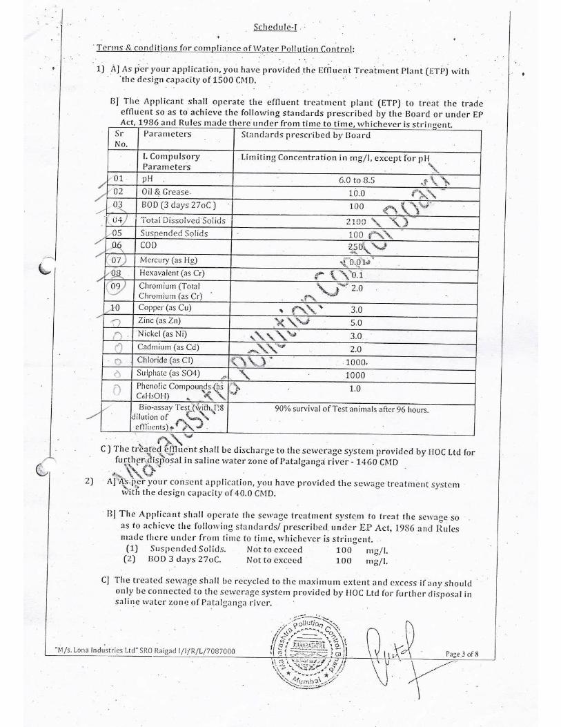
ANNEXURE ANNEXURE ANNEXURE ANNEXURE ––––
ADDITIONAL ATTACHMENTADDITIONAL ATTACHMENTADDITIONAL ATTACHMENTADDITIONAL ATTACHMENTSSSS

PLOT LAYOUT PLANPLOT LAYOUT PLANPLOT LAYOUT PLANPLOT LAYOUT PLAN

HYPO TANK95
GREEN PLANT 97
ABSORPTIONSYSTEM 96
COPPER RECOVERY PLANT AREA 98
OFFICE 22 PARKING
23
R & D BUILDING
24
MA
NA
GE
RS
BU
ILD
ING
1
0
WO
RK
ER
S Q
UA
RTE
RS
9
WO
RK
ER
S Q
UA
RTE
RS
8
SUPERVISORS QUARTERS 12
MESS 11
STORE BATHROOM
16
GUEST HOUSE 13
GO
DO
WN
15
GODOWN14
EXTENSION OFPACKING ROOM 29
PACKING GODOWN 28
STORE ROOM 27
R O
A D
RE
AC
TOR
& S
OLV
EN
TR
EC
OV
ER
Y U
NIT
,AB
SO
RB
ER
UN
IT &
VA
CC
UM
DR
YIN
G U
NIT
(EX
ISTI
NG
)
34
TREATMENTUNIT & S.F.D 36
7
S.F.D 41
6
TREATMENT UNIT 39
IBN CPC PLANT 40
NB CPC PLANT 37
HOT OIL UNIT 38
NITRO BENZENE &AMMONIA TANKS, SEPERATORUNIT,EJECTOR SYSTEM FORVACCUM DRYING UNIT. 32
BOILER ROOM 47
CP
C/C
OP
C/B
ET
A/R
ED
EFF
LUE
NT
CO
LLE
CT
ION
TA
NK
CANTEEN 19
15 A
WORKERSLOCKERS
20
CYCLE STAND 2
OPERATORS QUARTERS
3
SE
PTI
C T
AN
K
7
PUNCHING ROOM 21
TANK FARM AREA
48 A 49 A
P L
A N
T A
T I
O N
SUBSTATION 75
NEW O.N.T PLANT
74
I.B.M PLANT
73
QAC 72
BRIQUITTE STORAGE GODOWN
70
QA GODOWN 71
IBMNTOWER 76 C
HLO
RIN
E T
ON
NER
93
BALL MILL13.0x12.760 83
STAND BED 82
BACK WASH TANKMIXING TANK
80DOSING TANKGODOWN 78
ALUMGODOWN 79
P L A N T A T I O N
MANSOUN STORAGESUDGE SHEED
67
VTB
10,V
TB15
,VTB
20
10
0 A
65
METHENOL STORAGE TANK
44
EXT. BY 2500 MM
12000 LTR MS TANK 43
FURNACE OIL STORAGE 42
OLD
BA
LL M
ILL
R &
D A
ND
QC
51
NEW ALPHA PLANTGR.+ 2'ND FLOOR 52
GROUND FLOOR, FIRST FLOOR2'ND FLOOR FOR NEW ALPHA
PIGMENT TREATMENT & DRYING AREA
50
DRYING AREA,DRUM DRYER AREA,MILLING REACTION & BLENDINGAREADRYING AREA,FILTER PRESS AREA
49
FILTER PRESS AREAOLD ALPHA PLANT
WO
RK
SH
OP
56
R O
A D
R O A D
ALP
HA
EFF
LUE
NT
CO
LLE
CTI
ON
TA
NK
6
098%
H S
O4
57
2
DLE
UM
TA
NK
58
PIL
L S
ULP
HU
RIC
A
CID
TA
NK
59
P L A N T A T I O N
N A L A
GRAVITY STAND FILTER
WORKING PLATFORM
TREA
TMEN
T
PLA
NT
8184
85
N
6
W.C.
5
STAFF
QUARTERS
4
R O A D
HOTOILUNIT45
TH
ER
MO
PA
C
UN
IT 4
6S
TA
CK
R O A D
R O
A D
CHAMBER94
COOLING TOWER 91
COOLING TOWER 92
NEW GREENEFF.TREATMENT 99
C O M P O U N D W A L L
84
85
QA PLANT
86
OLD IBN PLANT
87
NEW ONT PLANT
88
89
OLD IBM TOWER
90
ONT-CPC SCRUBBING TOWER
91
AlCl3 GODOWN
92
ALLUM GODOWN
93
DOSING TANK
94
TREATMENT PLANT
95
BACK WASH TANK,MIXING TANK
96
BALL MILL
97
98
99
100
101
102
103
104
105
PUMP HOUSE
MIXING TANK
FEED TANK
GRAVITY STAND FILTER
WORKING PLATFORM
QA DISTILLATION TANK
COOLING TOWER
TANK-1
Q.A.GODOWN
SUBSTATION
EXISTING AREA STATEMENT
SRNO. NAME OF STRUCTURE GR.FL.
AREAIN SQ.M
1'ST.FL.AREAIN SQ.M
2'ND.FL.AREAIN SQ.M
3'RD.FL.AREAIN SQ.M
2
3
4
5
6
7
SCALE1:60
DWG . NO.-
TITLE:--
PROJECT:-PLOT PLAN
LONA INDUSTRIES LTD.LADIVALI (NEAR RASAYANI)
TALUKA - PANVEL , DIST.RAIGAD-410207
SHEET1 OF 1
REV. DATE. DRAWN CHECKED APPD.
0 00/00/2016 SHAILESH S.R.GUPTE S.R.GUPTE
HCL TANK 30
PROPOSEDAMMONIUM CHLORIDEPLANT 31
GODOWN 33
BETA BLUE 53
ESR
VTB 64
HT ISOLATOR 62
HTMETERING UNIT 63
SRNO. NAME OF STRUCTURE
61
62
63
64
65
66
67
68
69
70
71
72
73
CAR SHED
74
75
76
77
78
79
80
81
82
HT ISOLATOR
HT METERING UNIT
VTB-20
VTB-10,15
COAL SHED
MANSOON SLUDGE STORAGE SHED
QA TANK FARM
HOLD PUMP
GODOWN
GR.FL.AREAIN SQ.M
1'ST.FL.AREAIN SQ.M
2'ND.FL.AREAIN SQ.M
3'RD.FL.AREAIN SQ.M
SRNO. NAME OF STRUCTURE
GR.FL.AREAIN SQ.M
1'ST.FL.AREAIN SQ.M
2'ND.FL.AREAIN SQ.M
3'RD.FL.AREAIN SQ.M
COAL SHED 66
69
QA
DIS
TILA
TIO
N
PL
AN
T 9
0
STP17
25
43
CPCCEMENTATION 55
SECURITY CABIN 1 CAR SHAID
61
COPPER RECOVRY PLANT 100
8
9
10
11
12
13
14
15
16
17
18
19
20
21
22
23
24
25
26
27
28
29
30
31
32
33
34
35
36
37
38
39
40
41
42
43
44
45
46
47
48
49
50
51
52
53
54
55
56
57
58
59
60
83
CHLORINE TUNNER SHED
CHEMBER
HYSOL TANK
ABSORPTION SYSTEM
GREEN PLANT EFFLUENTTREATMENTCOPPER RECOVERY PLANTAREA
GREEN PLANT
COPPER RECOVERY PLANTSHED
BIO REACTOR
SECONDARY CLARIFIER
ELECTRICAL PANEL ROOM
HOLD SUMP TANK
COLLECT6ION TANK
106TREATED WASTE WATERTANK
PROPOSED BETABLUE EXTENSION 54
ALPHATEA BOOTH
R O A D
BACK WASHDISCHARGE PUMP FOUNDATIONS
BACK WASHDISCHARGE PUMP FOUNDATIONS
NISOLTANK
122
R.M.GODOWN 18
26
35
48
68
77
86
87
88
89
COOLING TOWER 127
COOLING TOWER 126
101 FUTURE EXPANTION 101
102
103
104
105
106
107 108
111
116
109 110
113
112 118
114
117
119
121
120
115
123
124
125
1 SECURITY CABIN
CYCLE STAND
OPERATORS QUARTERS
STAFF QUARTERS
W.C
SEPTIC TANK
WORKERS QUARTERS
MANAGERS BUILDING
MESS
SUPERVISORS QUARTERS
GUEST HOUSE
GODOWN
STORE BATHROOM
STP
RAW MATERIAL GODOWN
CANTEEN
WORKERS LOCKERS
PUNCHING ROOM
ADMIN OFFICE
PARKING
R&D BUILDING
ESR
ALPHA TEA BOOTH
STORE ROOM
PACKING GODOWN
EXTENSION OF PACKING ROOM
HCL TANK
AMMONIUM CHLORIDE PLANT
NITRO BENZENE & AMMONIUM TANKSEPERATOR UNIT EJECTOR SYSTEMFORVACUUM DRYING UNIT
GODOWN
PMD PLANT
TREATMENT UNIT & SFD
NB CPC PLANT
HOT OIL UNIT
TREATMENT UNIT
IBN CPC PLANT
SFD
FURNACE OIL STORAGE
MS-TANK
METHENOL STORAGE TANK
HOT OIL UNIT
THERMOPAC UNIT
BOILER ROOM
CPC/COPC/BETA/RED EFFLUENTCOLLECTION TANK
PIGMENT TREATMENT & DRYINGAREA
OLD BALL MILL R&D & QC
BETA BLUE/EMULSION
WORKSHOP
CPC CEMENTATION
BATHROOM
98% H2SO4
CAR SHED
WORKERS QUARTERS
GODOWN
REACTOR & SOLVENT RECOVERY UNITABSOBLE UNIT & VACUUM DRYINGEXISTING UNIT
OLD ALPHA PLANT
NEW ALPHA PLANT
OLUM TANK
PILT SULPHURIC ACID TANK
ALPHA EFFLUENT COLLECTION TANK
PUMP HOUSE
COOLING TOWER
107
88.45
15.97
285.18
235.84 235.84 235.84
92.50
5.77
103.55
97.41
182.48
45.04
238.17
178.84
71.82
145.41
15.53
12.00
2000.00
333.88
177.95
23.98
198.49
77.94
185.60 188.60 188.60
10.32
36.56
400.56
50.00
165.88
408.76
752.00
590.95
403.88
35.41
35.41
225.81
945.40 853.46 756.65
522.64
135.65
217.03
377.90
283.17
846.80 283.93
595.64
110.00 85.00 66.00
64.00
148.02
884.92
570.02
535.40
159.17
351.94
1452.00
140.00 140.00
64.00
123.27 - -
72.41
33.03
230.85
115.85
43.20
34.12
76.14
4.39
927.18 927.18 927.18 463.59
11.04
198.49 198.49
341.76
517.88
76.14
76.14
666.75
500.02
76.14
76.14
54.60
702.94
43.20
25.3
25.3
245.00
405
300.00
152.02
6.05
360.00
180.00
332.09 332.09
20.98
20.98
122.34
122.34
5.88
818.82
204.06
35.41
35.41
35.41
35.41
64.05
48.12
74.86
333.17 333.17
144.99 144.99
144.99
78.64
18.37
48.74
403.88
128
20.98 20.98
129
PROPOSED PLANTATION
PROPOSED PLANTATION
130
131
RAIN HARVESTING
RAIN HARVESTING
STORM DRAINS GUTTER
RAIN HARRESTING
FIRE HYDRANT
GREEN BELT
PROPOSED PLANTATION
108
109
110
111
112
113
114
115
116
117
118
119
120
121
122
123
124
125
126
127
TANK-2
M.E.E PLANT
HYSOLP TANK
EQULISATION TANK
LIME STORM VAT
ETP LAB
SRNO. NAME OF STRUCTURE
GR.FL.AREAIN SQ.M
1'ST.FL.AREAIN SQ.M
2'ND.FL.AREAIN SQ.M
3'RD.FL.AREAIN SQ.M
FILTER PRESS AREA
RED COLLECTION TANK
CLARIFIER NO-4
ALPHA TANK
AMMONIA TANK
AMINE TANK
CAUSTIC TANK
COOLING TOWER
ETP CLARIFIER NO-2
NEUTRILISATION TANK
ETP CLARIFIER NO-1
35ıMTR COLLECTION TANK
250ıMTR COLLECTION TANK
COOLING TOWER
166.00 70.00 70.00
590.95
64.05
48.12
94.71
101.72
50.44
264.33
180.00
25.00
50.28
119.00
20.00
10.69
40.00
67.50
47.14
25.40
225.01
225.01
NH CI SCRUBBING TOWER128 20.98 20.9820.984
129 SLUDGE DRYING BED 600.00
130 36.00
131 EMULSION
AREA DATA FOR COMPLETE PLANT
PLOT AREAPERIMETERTOTAL BUILT-UP AREA
109266.3 SQ. M (27 ACRE)1388.986 M.29069.09 SQ. M.
EXISTING GREEN AREA 32779.89 SQ. M.
106.64
212.46
2623.53
119.00
15.00
TOTAL 29069.09 4700.49 2978.84 570.23
182.48 142.48
351.94 351.94
EXISTING OPEN AREA 47417.32 SQ. M.
PRODUCED BY AN AUTODESK EDUCATIONAL PRODUCTPR
OD
UC
ED B
Y A
N A
UTO
DES
K E
DU
CA
TIO
NA
L PR
OD
UC
TPRODUCED BY AN AUTODESK EDUCATIONAL PRODUCT
PRO
DU
CED
BY A
N A
UTO
DESK
EDU
CA
TION
AL PR
OD
UC
T
CONSENT TO OPERATE


MASS BALANCE

1. MATERIAL BALANCE FOR COPPER PTHALOCYANINE CRUDE
Batch size: 1.3 MT Production: 280 MT/month
Production: 9.333 MT /day No.of batches: 7.18 /day
Sr.
No. Raw
material
Input
Kg/batch
Liquid
effluent
kg/bx
Recycle / reused
kg
Solid
waste
kg
Emission
kg
Losses
kg Product in
kg / batch
Output
total, kg
1 PAN 1431 4428 Hisol
2 Urea 1500 solvent
3 CuCl 258 164 ammonia
4 NH4Cl 50 gas
5 Hisol 4500 20000 -
washing 20000 water
1014 -CO2
870
water in 1300
6 Recyled
ammonia 164
recycle
Nil Cake CPC
7 Sulfuric
Acid (20%) 869
8760
Mother
liq.
8
MEE
recycled
water
8035
to MEE
9
Recycle
water
(wash)
20000
271 ammonia
10
Fresh
water 20000
to NH4Cl
Total 56807 20000 33623 1014 870 1300 56807

2. MATERIAL BALANCE FOR COPPER PTHALOCYANINE GREEN Batch size: 2 MT No.of batches: 2/day
Production: 120 MT/month Production: 4 MT /day
Sr.No. Raw
material
Input
Kg/batch
Liquid
effluent
kg/bx
Recycle /
reused
Kg
Solid
waste
Kg
Emission
Kg
Losses
Kg
Product
in
kg /
batch
Output
total,
kg
1 CPC 1075
2 AlCl3 3475 2021 Green
3 NaCl 650
4 CuCl2 151 3462 HCl 30 %
5 Chlorine 2330
186238 1875
solvent Nil Nil 2470 byproduct
6
Caustic lye
(47%) 1418
recovery
water
in
7 Solvent 2015 cake 3005 Hypo soln
8
Water for
drowning 26500
35000
filterpress
wash byproduct
9
Water +
condensate 8000
10
Water for
washing 176700
27243 PAC soln
11
Recycled
water 35000
12
Water for
HCl & hypo 4000
byproduct
Total 36875 2470 35731 261314

3. MATERIAL BALANCE FOR COPPER PTHALOCYANINE ALPHA BLUE
Batch size: 0.665 MT No.of batches: 3.5 /day
Production: 2.33MT /day Production: 70 MT/month
N
o.
Raw material
Input
Kg/batch
Liquid
effluent
kg/bx
Recycle /
reused
Kg
Solid
waste
Kg
Emis
sion
Kg
Losses
Kg
Product in
kg / batch
Output
total, kg
1
Copper
phthalocyanine
crude 700
2 Sulfuric acid 3200 665 alpha
3 Caustic lye (47%) 80 68251 8800 Nil Nil 1862 blue
4 Surfactant 2 water
water in 13404
spent
acid
5 Process water 25200 cake
(byprodu
ct
6 Fresh water (wash) 55000 for sale)
7 Recycled water
(wash) 8800
Total 92982 68251 8800 1862 14069 92982
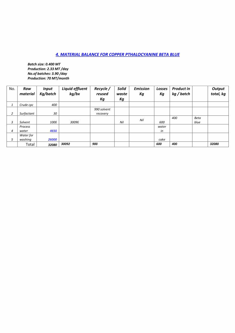
4. MATERIAL BALANCE FOR COPPER PTHALOCYANINE BETA BLUE
Batch size: 0.400 MT
Production: 2.33 MT /day
No.of batches: 3.90 /day
Production: 70 MT/month
No. Raw
material
Input
Kg/batch
Liquid effluent
kg/bx
Recycle /
reused
Kg
Solid
waste
Kg
Emission
Kg
Losses
Kg
Product in
kg / batch
Output
total, kg
1 Crude cpc 400
2 Surfactant 30
990 solvent
recovery
3 Solvent 1000 30090 Nil Nil
600
400 Beta
blue
4
Process
water 4650 water
in
5
Water for
washing 26000
cake
Total 32080 30092 900 600 400 32080

5. MATERIAL BALANCE FOR QUINACRIDONE (QA) Pink & Red
Batch size: 0.250MT
Production: 0.750 MT /day
No.of batches: 3/day
Production: 22.500 MT/month
Sr.No
.
Raw
material Input
Kg/batc
h
Liquid
effluen
t kg/bx
Recycl
e /
reused
Kg
Solid
wast
e
Kg
Emissio
n
Kg
Losse
s
Kg
Produc
t in
kg /
batch
Outpu
t
total,
kg
1 DMSS 200
2 Methanol 2528
3
p-
Toluidine/
Aniline 200
5
Caustic
flakes 160
6 Resist salt 176 100231
2008
methan
ol
recover
y Nil Nil 1670 250 Pigment
8
Hydrochlori
c acid 600
water
in 3500
by
product
9
Phosphoric
acid 455
900 IBA
recovery
cake
phospori
c
10
Phosphorou
s Pentoxide 650
acid
11
iso- Butanol
(IBA) 960
12 Caustic lye 30
13
Water
(process +
washing) 102600
108559 100231 2908 0 1670 3750 108559

6. MATERIAL BALANCE FOR COPPER PTHALOCYANINE BLUE ZCN
Batch size: 0.570MT Production: 0.411 MT /day
No.of batches: 0.721/day Production: 12.33 MT/month
Sr.No. Raw material
Input
Kg/batch
Liquid
effluent
kg/bx
Recycle /
reused
Kg
Solid
waste
Kg
Emission
Kg
Losses
Kg
Product in
kg / batch
Output
total, kg
1 Cl- CPC 600
2 Sulfuric acid 3000 570 Blue ZCN
3 Caustic lye (47%) 80 54012 8000 water Nil Nil 1900
4 Surfactant 2 water in 12700 spent acid
5 Process water 23500 cake (byproduct
Water for washing 42000
6 Recled water 8000 for sale)
Total 77182 54012 8000 13270 77182
7. MATERIAL BALANCE FOR MONOSULPHO COPPER PHTHALOCYANINE (SCL-PC)
Batch size: 0.317MT Production: 0.05 MT /day
No.of batches: 5/Month Production: 1.5 MT/month
Sr.No. Raw material
Input
Kg/batch
Liquid
effluent
kg/bx
Recycle /
reused
Kg
Solid
waste
Kg
Emission
Kg
Losses
Kg
Product in
kg / batch
Output
total, kg
1 CPC crude 300 317 SCLPC
2 H2SO4 1525
3 Oleum 1525 16233 Nil Nil Nil 1800 21000 spent acid
4 Process water 16000 water in (byproduct
5 Water for washing 20000 cake for sale)
Total Input
39350 16233 0 0 1800 21317 39350

8. MATERIAL BALANCE FOR PIGMENT EMULSION
Batch size: 0.500MT Production: 3 MT /day
No.of batches: 6/day Production: 90MT/month
Sr.No. Raw material
Input
Kg/batch
Liquid
effluent
kg/bx
Recycle /
reused
Kg
Solid
waste
Kg
Emission
Kg
Losses
Kg
Product in
kg / batch
Output
total, kg
1 Pigment 200
2 Dispersing agent 77 Nil Nil Nil Nil Nil 500 Pigment
3 Water 223 Emulsion
Total Input 500 0 0 0 0 500 500

MANUFACTURING PROCESS

1. COPPER PHTHALOCYANINE (CPC) PROCESS : 2.
PROPOSED : COPPER PHTHALOCYANINE (CPC) PROCESS :
Complexation & distillation : Phthalimide reaction mass is received into CPC reactor from phthalimide reactor. This mass contains solvent, phthalimide and urea. Copper salt is then charged. Reaction mass is heated to 180- 200°C and maintained till completion of reaction. Ammonia and carbon dioxide gas liberated is passed through phthalimide reactor, where part of ammonia reacts with phthalic anhydried (which taken for next CPC batch) to form phthalimide and excess ammonia is further stripped in hydrochloric acid to form ammonium chloride. After completion of reaction, batch is transferred to rotary vacuum dryer where solvent is distilled out. Crude product is slurried with water and transferred to purification vessel. Purification & filtration : Slurry of crude product is received from rotary vacuum dryer into purification vessel. Sulfuric acid is added and heated to dissolve the impurities. Reaction mass is then filtered in filterpress, washed with hot water, aerated and product is discharged in cake form. Drying & packing : Cake is dried in spin flush dryer and product ‘Copper phthalocyanine’ is obtained in powder form which is then packed in bags.
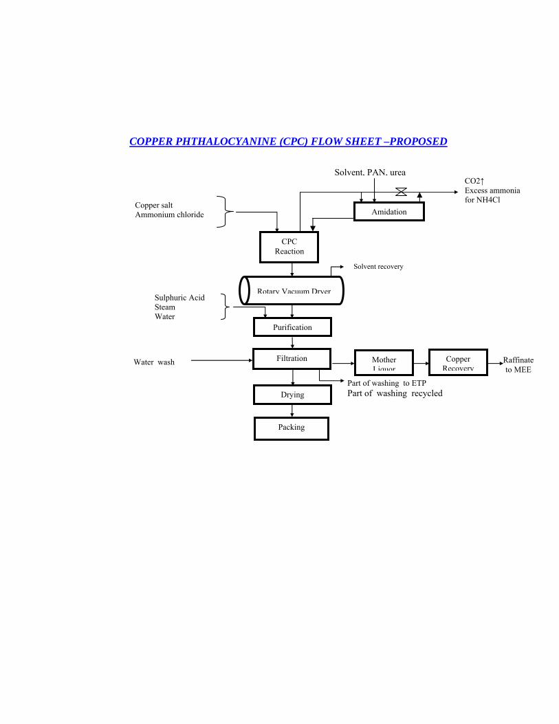
COPPER PHTHALOCYANINE (CPC) FLOW SHEET –PROPOSED
Drying
Filtration Water wash
Part of washing to ETP Part of washing recycled
Mother Liquor
Copper Recovery
Raffinate to MEE
CPC Reaction
Copper salt Ammonium chloride
Rotary Vacuum Dryer
Solvent recovery
Purification
Packing
Sulphuric Acid Steam Water
Amidation
Solvent, PAN, urea CO2↑ Excess ammonia for NH4Cl
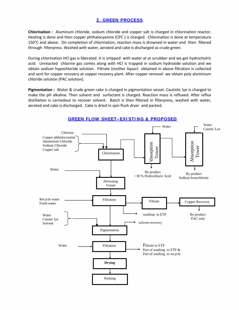
2. GREEN PROCESS
Chlorination : Aluminum chloride, sodium chloride and copper salt is charged in chlorination reactor. Heating is done and then copper phthalocyanine (CPC ) is charged. Chlorination is done at temperature 150°C and above. On completion of chlorination, reaction mass is drowned in water and then filtered through filterpress. Washed with water, aerated and cake is discharged as crude green. During chlorination HCl gas is liberated. It is srtipped with water at at scrubber and we get hydrocholric acid. Unreacted chlorine gas comes along with HCl is trapped in sodium hydroxide solution and we obtain sodium hypochloride solution. Filtrate (mother liquor) obtained in above filtration is collected and sent for copper recovery at copper recovery plant. After copper removel we obtain poly aluminium chloride solution (PAC solution). Pigmentation : Water & crude green cake is charged in pigmentation vessel. Cautistic lye is charged to make the pH alkaline. Then solvent and surfactant is charged. Reaction mass is refluxed. After reflux distillation is carriedout to recover solvent. Batch is then filtered in filterpress, washed with water, aerated and cake is discharged. Cake is dried in spin flush dryer and packed.
Pigmentation
GREEN FLOW SHEET–EXISTING & PROPOSED
Filtration Recycle water Fresh water
Filtrate to ETP Part of washing to ETP & Part of washing to recycle
solvent recovery
Water By product
~30 % Hydrochloric Acid
By product PAC soln
Copper Recovery
washing to ETP
Filtration
Packing
Drying
By product Sodium hypochlorite
Chlorination
Copper phthalocyanine Aluminium Chloride Sodium Chloride Copper salt
Abs
orpt
ion
Tow
er
Drowning Vessel
Water Caustic Lye
Filtrate
Water
Water Caustic lye Solvent
Chlorine
Abs
orpt
ion
Tow
er
Water

3. ALPHA BLUE PROCESS :
Acid pasting : Sulfuric acid is charged into pasting vessel. Copper phthalocyanine (CPC) is charged. Heated to dissolve the CPC completely. Then this reaction mass is drowned in water , filtered through filterpress. Washed with water, aerated and cake is discharged as crude alpha cake. Filtrate (mother liquor) obtained is collected as spent sulfuric acid. Pigmentation : Water & crude alpha cake is charged in pigmentation vessel. Cautistic lye is charged to make the pH alkaline and surfactant is charged. Reaction mass is heated and maintained at elevated temperature. Batch is then filtered through filterpress, washed with water, aerated and cake is discharged. Cake is dried in spin flush dryer and packed.
ALPHA BLUE FLOW SHEET –EXISTING & PROPOSED
Filtration Fresh water + recycle
Part of washing to ETP Part of washing recycle
Sulfuric Acid Copper phthalocyanine
Pigmentation
Filtrate to ETP
Filtration Water
Acid Pasting
Drowning
Washing to ETP
Packing
Drying
Water
Spent acid by product
Water Caustic lye Surfactant

4. BETA BLUE PROCESS :
Pigmentation : Water is taken in pigmentation vessel. Ballmilled copper phthalocyanine and solvent is charged. Surfactant is charged and reflux is done. Solvent is then distilledout. Batch filtered through filterpress, washed with water, aerated. Cake is discharged, dried, pulverized and packed.
BETA BLUE FLOW SHEET –EXISTING & PROPOSED
Pigmentation
Mother liquor & washing to ETP
Filtration Water
Packing
Drying
Water Surfactant Solvent Copper phthalocyanine (ballmilled cpc)
Solvent Recovery

QUINACRIDONE PIGMENT PROCESS Condensation (I): Solvent , DMSS, amine (p-toluidine / aniline) are charged in condensation reaction. Reaction mass is refluxed. After completion of reaction mass, batch is filtered through filterpress. Washed with water, aerated and cake is discharged. Hydrolysis & acidification (II): Solvent , cake, water, caustic lye and resist salt charged to hydrolysis vessel. Reaction mass is refluxed. Then solvent is recovered by distillation. Rection mass clarified by passing through the filter. Filtrate acidified with hydrochloric acid to precipitate the product. Batch filtered through filterpress, washed with water, aerated, discharged and dried. Cyclization (III) : Phosphoric acid and phosphorous pentoxide are charged to cyclization reactor and heated. Step II material is then charged. Batch heated and maintained to complete the reaction. After completion of holding, reaction mass drowned in water, stirred and filtered through filterpress. Washed with water, aerated and cake is discharged. Filtrate (mother liquor) is collected as spent phosphoric acid. Pigmentation (IV) : Water and cake is charged in pigmentation vessel. Caustic lye is charged to make pH alkaline and then solvent charged. Heating is applied and batch maintained under the pressure. Then batch cooled and filtered through filterpress, washed by water, aerated and cake is discharged. Cake is dried, pulverized and packed. Filtrate (mother liquor) is collected and subjected for distillation to recover the solvent.
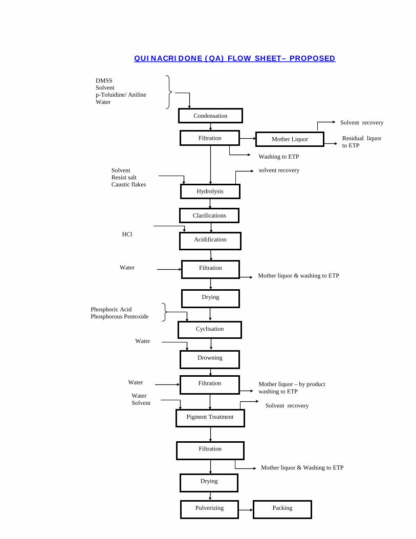
Water QUINACRIDONE (QA) FLOW SHEET– PROPOSED
DMSS Solvent p-Toluidine/ Aniline Water
Condensation
Filtration
Acidification
Filtration
Drying
HCl
Water Mother liquor & washing to ETP
Mother liquor – by product washing to ETP
Water
Water
Hydrolysis
Clarifications
Solvent Resist salt Caustic flakes
solvent recovery
Phosphoric Acid Phosphorous Pentoxide
Cyclisation
Filtration
Pigment Treatment
Drying
Filtration
Drowning
Water Solvent Solvent recovery
Mother liquor & Washing to ETP
Pulverizing Packing
Mother Liquor
Solvent recovery
Residual liquor to ETP
Washing to ETP
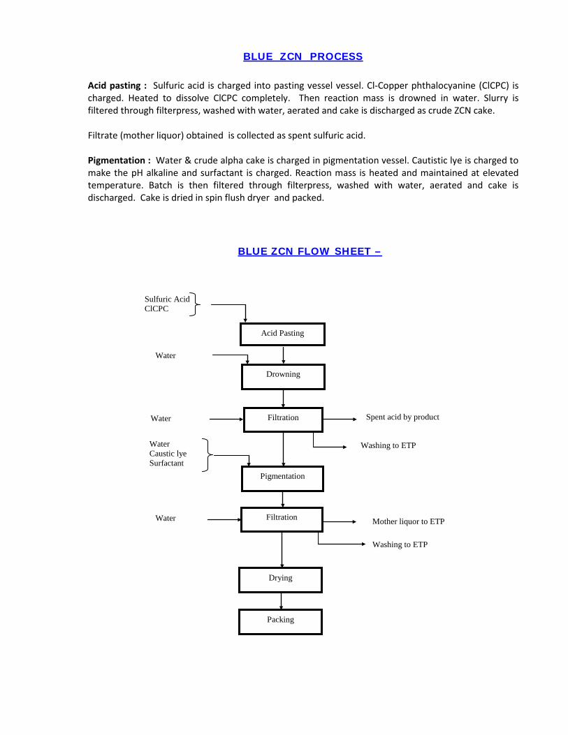
BLUE ZCN PROCESS
Acid pasting : Sulfuric acid is charged into pasting vessel vessel. Cl-Copper phthalocyanine (ClCPC) is charged. Heated to dissolve ClCPC completely. Then reaction mass is drowned in water. Slurry is filtered through filterpress, washed with water, aerated and cake is discharged as crude ZCN cake. Filtrate (mother liquor) obtained is collected as spent sulfuric acid. Pigmentation : Water & crude alpha cake is charged in pigmentation vessel. Cautistic lye is charged to make the pH alkaline and surfactant is charged. Reaction mass is heated and maintained at elevated temperature. Batch is then filtered through filterpress, washed with water, aerated and cake is discharged. Cake is dried in spin flush dryer and packed.
BLUE ZCN FLOW SHEET –
Filtration Water
Washing to ETP
Sulfuric Acid ClCPC
Pigmentation
Mother liquor to ETP Filtration Water
Acid Pasting
Drowning
Washing to ETP
Packing
Drying
Water
Spent acid by product
Water Caustic lye Surfactant

BLUE SCL-PC PROCESS
Sulfonation : Sulfuric acid and oleum is taken in sulfonation vessel. Copper phthalocyanine (CPC) is charged. Heated to dissolve the CPC completely. Then this reaction mass is drowned in water , filtered through filterpress. Washed with water, aerated and cake is discharged and packed as blue SCL-PC .
SCLPC FLOW SHEET
Filtration Water
Sulfuric Acid Oleum Copper phthalocyanine
Packing
Sulfonation
Drowning
Washing to ETP
Water
Spent acid by product
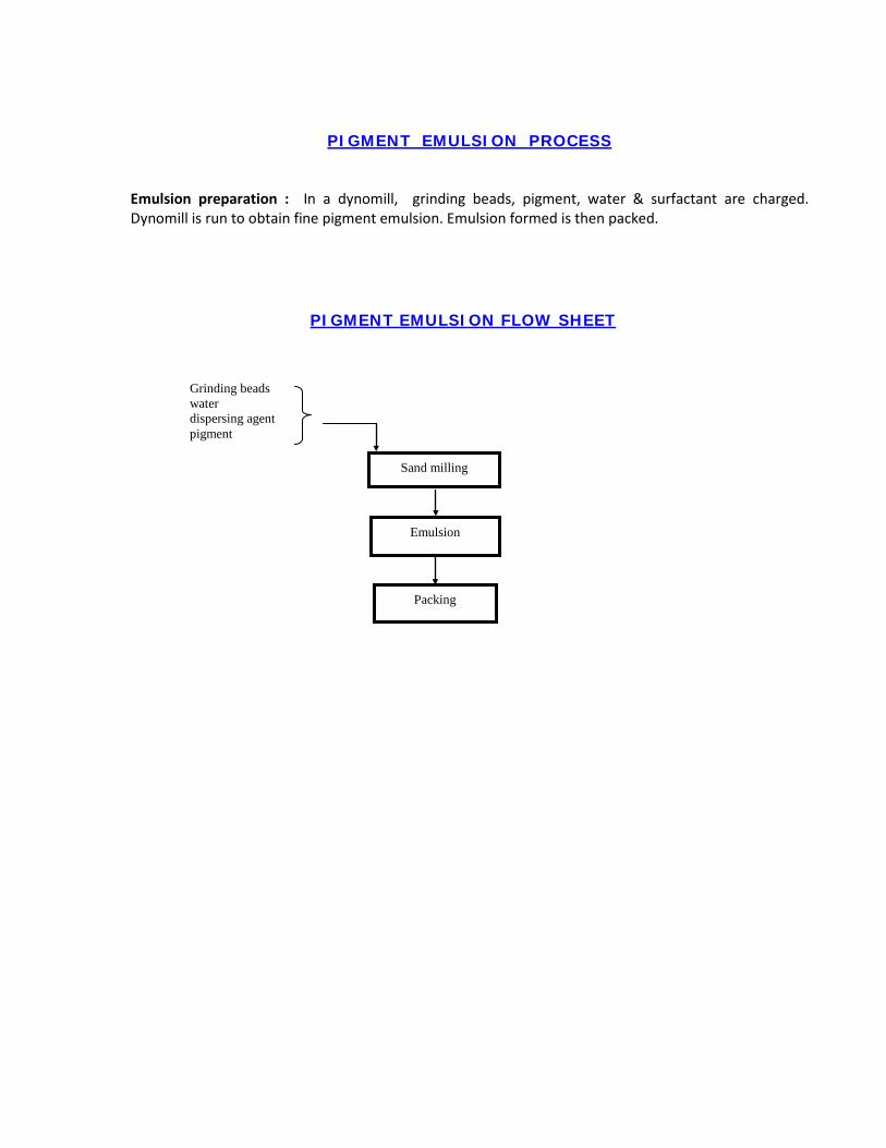
PIGMENT EMULSION PROCESS
Emulsion preparation : In a dynomill, grinding beads, pigment, water & surfactant are charged. Dynomill is run to obtain fine pigment emulsion. Emulsion formed is then packed.
PIGMENT EMULSION FLOW SHEET
Packing
Grinding beads water dispersing agent pigment
Sand milling
Emulsion

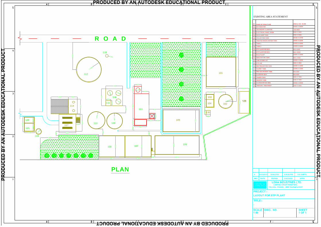
ETP ETP ETP ETP LAYOUTLAYOUTLAYOUTLAYOUT
R O A D
5000
1740
045
00
8500
2998
5500
4000
4000
5000
5000
11500
1150
33500
3500
1000
0
600012000
1000
0
7000
5425
3825
30500
31972400
1787517875
1420
0
1420
0
1250
0
25100
1470
0
1000
020
500
20503
5500
3500
5500
7900
4500
2740011500
1150
0
3000
3000
12400
4992 8000
2500
3000
Ï17250
Ï2000
Ï12000 Ï
11000
Ï3500
Ï3500
Ï3500
Ï3000
Ï4000
Ï9800
1862
5
SCALE1:60
DWG . NO.-
TITLE:--
PROJECT:-LAYOUT FOR ETP PLANT
LONA INDUSTRIES LTD.LADIVALI (NEAR RASAYANI)
TALUKA - PANVEL , DIST.RAIGAD-410207
SHEET1 OF 1
REV. DATE. DRAWN CHECKED APPD.
0 01/12/2017 SHAILESH S.R.GUPTE S.R.GUPTE
PLAN
101
102
103
104
105
106107108
109110
111
116
115
113
118
114
117
119
121
120
EXISTING AREA STATEMENT
SRNO. NAME OF STRUCTURE
101
AREA & DIA IN MM
20500 X 20500
DIA-9800
5500 X 3500
5500 X 5500
25100 X 14700
30500 X 12500
BIO REACTOR
102
103
104
105
106
107
108
109
110
111
113
114
115
116
117
118
119
120
121
17875 X 14200
17875 X 14200
DIA-11000
DIA- 12000
26900 X 10000
DIA- 17250
18000 X 10000
3500 X 3500
11500 X 11500
11500 X 11500
DIA-2000
DIA-4000
2825 X 7000
5425 X 7000
SECONDARY CLARIFIER
ELECTRICAL PANEL ROOM
HOLD SUMP TANK
COLLECTION TANK
TREATED WASTE WATER TANK
TANK-1
ETP CLARIFIER NO-2
M.E.E PLANT
EQULISATION TANK
LIME STORM VAT
ETP LAB
NEUTRILISATION TANK
SLURRY TANK
RED COLLECTION TANK
CLARIFIER NO-4
35ıMTR TANK
250ıMTR TANK
TANK-2
ETP CLARIFIER NO-1
129
3000
0
20000
129 20000 X 30000SLUDGE DRYING BED
3000
3000
2000
130
130 3000 X 3000TERTIARY TREATMENT
9900
PRO
DU
CED
BY
AN
AU
TOD
ESK
ED
UC
ATI
ON
AL
PRO
DU
CT
PRODUCED BY AN AUTODESK EDUCATIONAL PRODUCTPR
OD
UC
ED B
Y AN
AU
TOD
ESK ED
UC
ATIO
NA
L PRO
DU
CT
PRODUCED BY AN AUTODESK EDUCATIONAL PRODUCT

WATER BUDGETWATER BUDGETWATER BUDGETWATER BUDGET

Table 1 Details of Water Requirement
No. Description
Water Consumption (M3/Day)
Existing Expansion Total After Expansion
1 Domestic #50 - #50
2 Industrial
Process 1504.43 (#1391.23+ $113.2)
255.28 (#153.28+$60+*42)
1767.63 (#1416.43+$253.2+*98)
Scrubber #49.66 - #8
Laboratory + Floor
#15 - #15
Boiler Makeup
#144 #110 #254
Cooling Tower Make up
#110 #30 #140
DM Water Backwash
#10 #15 #25
Industrial Total
1833.09 (#1719.89+$113.2)
410.28 (#308.28+$60+*42)
2209.63 (#1858.43+$253.2+*98)
3 Gardening 50 (#20 + @30)
- 50 (#20 + @30)
Total (1+2+3)
1933.09 (#1789.89+$113.2+
@30)
410.28 (#308.28+$60+*42)
2309.63 (#1928.43+$253.2+*98+ @30
)
Note: # - Fresh water, $ - Recycled water , * - MEE water , @ - STP recycle

Table 2 Details of Effluent Generation
Sr.No.
Description Effluent generation (M3/Day) Existing Expansion Total after expansion
1 Domestic 40 - 40 2 Industrial
a. Processing 1290 148.52 1259 b. Laboratory + floor 15 - 15 c. Boiler Blow down 44 60 104 d. Cooling Tower blowdown
50 15 65
e. DM Plant back wash 10 15 25
Industrial Total 1409 238.27 1468

DETAILS OF BOILER, THERMIC
FLUID HEATER & D.G. SETS

• Details of Boiler, TFH and D.G. set and APC equipments to be provided for same are given in following table.
Table No.1 Details of Boiler
Sr. No.
Description Boiler Existing Expansion
1 2 3 4
1. Capacity 6 TPH 10 TPH 4 TPH 14 TPH 2. Fuel type FO Coal FO Coal 3. Fuel Quantity , T/D 8.3 24.6 4.32 37.46 4. Calorific value 10200 5400 10200 5400 5. Ash content, % 0.05 6-8 0.05 6-8 6. Sulphur content 3.5 0.5 3.5 0.5 7. Material of construction MS MS MS MS 8. Shape (round/rectangular) round round round round
9. Height, m (above ground level)
23 30 21 33
10. Diameter/size, in mtrs 1 1 0.8 1.2 11. Internal Diameter of the
stack (m) 0.98 0.98 0.78 1.09
12. Flue Gas Temp, °C 220 210 220 200 13. Exist gas velocity m/s 10 10 10 10 14. ID Fan Capacity m3/h 9000 18000 7200 34800 15. Gas flow rate in Nm3/Hr 9000 18000 7200 34800 16. Stack diameter at sampling
port mtrs 1 1 0.8 1.2
17. Control Equipment preceding the stack
No MDC + tremo cyclon
No MDC+ Bag Filter
Note: Under expansion existing 4 TPH boiler will be discontinued and 6 TPH boiler will be operated as standby.

Table No.2 Details of Thermic Fluid Heater
Sr. No.
Description Thermic Fluid Heater (TFH) Existing
TFH 1
TFH 2
TFH 3
TFH 4
TFH 5
1. Capacity 4 lac Kcal
4 lac Kcal
4 lac Kcal
4 lac Kcal
4 lac Kcal
2. Fuel type FO FO FO FO FO 3. Fuel Quantity , T/D 0.72 0.72 0.72 0.72 0.72 4. Calorific value 10200 10200 10200 10200 10200 5. Ash content, % 0.05 0.05 0.05 0.05 0.05 6. Sulphur content 3.5 3.5 3.5 3.5 3.5 7. Material of
construction MS MS MS MS MS
8. Shape (round/rectangular)
round round round round round
9. Height, m (above ground level)
16 16 16 16 16
10. Diameter/size, in mtrs 0.56 0.56 0.56 0.56 0.56
11. Internal Diameter of the stack (m)
0.54 0.54 0.54 0.54 0.54
12. Flue Gas Temp, °C 210 220 220 220 220
13. Exist gas velocity m/s 10 10 10 10 10
14. ID Fan Capacity m3/h 650 650 650 650 650
15. Gas flow rate in Nm3/Hr
650 650 650 650 650
16. Stack diameter at sampling port mtrs
0.56 0.56 0.56 0.56 0.56
17. Control Equipment preceding the stack
No No No No No
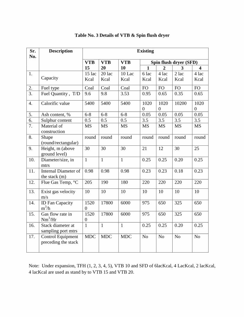
Table No. 3 Details of VTB & Spin flush dryer
Note: Under expansion, TFH (1, 2, 3, 4, 5), VTB 10 and SFD of 6lacKcal, 4 LacKcal, 2 lacKcal, 4 lacKcal are used as stand by to VTB 15 and VTB 20.
Sr. No.
Description Existing
VTB 15
VTB 20
VTB 10
Spin flush dryer (SFD) 1 2 3 4
1. Capacity
15 lac Kcal
20 lac Kcal
10 Lac Kcal
6 lac Kcal
4 lac Kcal
2 lac Kcal
4 lac Kcal
2. Fuel type Coal Coal Coal FO FO FO FO 3. Fuel Quantity , T/D 9.6 9.8 3.53 0.95 0.65 0.35 0.65
4. Calorific value 5400 5400 5400 10200
10200
10200 10200
5. Ash content, % 6-8 6-8 6-8 0.05 0.05 0.05 0.05 6. Sulphur content 0.5 0.5 0.5 3.5 3.5 3.5 3.5 7. Material of
construction MS MS MS MS MS MS MS
8. Shape (round/rectangular)
round round round round round round round
9. Height, m (above ground level)
30 30 30 21 12 30 25
10. Diameter/size, in mtrs
1 1 1 0.25 0.25 0.20 0.25
11. Internal Diameter of the stack (m)
0.98 0.98 0.98 0.23 0.23 0.18 0.23
12. Flue Gas Temp, °C 205 190 180 220 220 220 220
13. Exist gas velocity m/s
10 10 10 10 10 10 10
14. ID Fan Capacity m3/h
15200
17800 6000 975 650 325 650
15. Gas flow rate in Nm3/Hr
15200
17800 6000 975 650 325 650
16. Stack diameter at sampling port mtrs
1 1 1 0.25 0.25 0.20 0.25
17. Control Equipment preceding the stack
MDC MDC MDC No No No No

Table No. 4 Details of D. G. Sets
Sr. No.
Description D.G. Sets Existing
1. Capacity 500 KVA
250 KVA
180 KVA
62.5 KVA
2. Fuel type High speed diesel 3. Fuel Quantity 2568
Lit / Day
1320 Lit / Day
744 Lit/ Day
312 Lit/ Day
4. Calorific value 5. Ash content, % 0.1% 6. Sulphur content 1% 7. Material of construction MS 8. Shape (round/rectangular) Round 9. Height, m (above ground level) 4.5m 3.2m 2.7m 1.6m 10. Control Equipment preceding the
stack -- -- -- --

WATER PERMSSIONWATER PERMSSIONWATER PERMSSIONWATER PERMSSION
LETTERLETTERLETTERLETTER

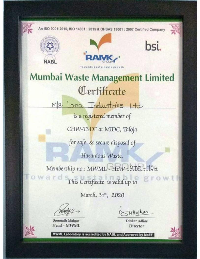
CHWTSCHWTSCHWTSCHWTSDF MEMBERSHIPDF MEMBERSHIPDF MEMBERSHIPDF MEMBERSHIP

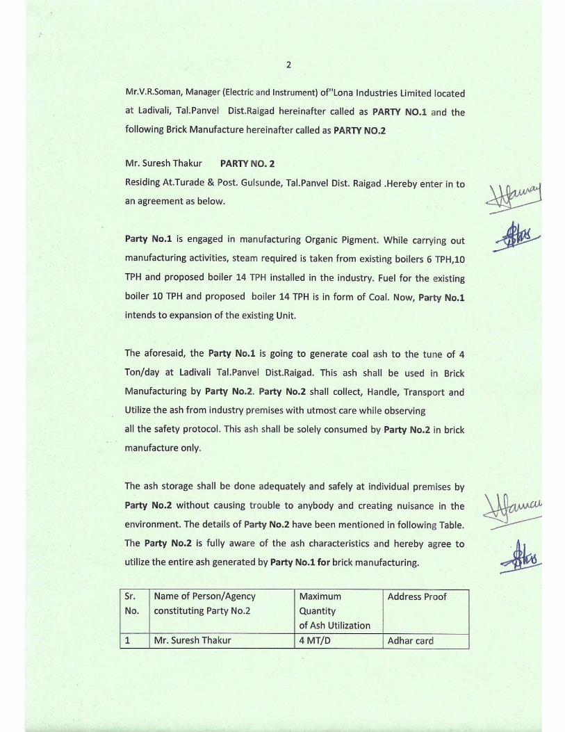
AGREEMENTAGREEMENTAGREEMENTAGREEMENT
WITHWITHWITHWITH
BRICK MANUFACTURER BRICK MANUFACTURER BRICK MANUFACTURER BRICK MANUFACTURER


CERTIFICATES & OTHER CERTIFICATES & OTHER CERTIFICATES & OTHER CERTIFICATES & OTHER
DOCUMENTSDOCUMENTSDOCUMENTSDOCUMENTS
REGISTRATION CERTIFICATE

GRAMPANCHAYAT NOC


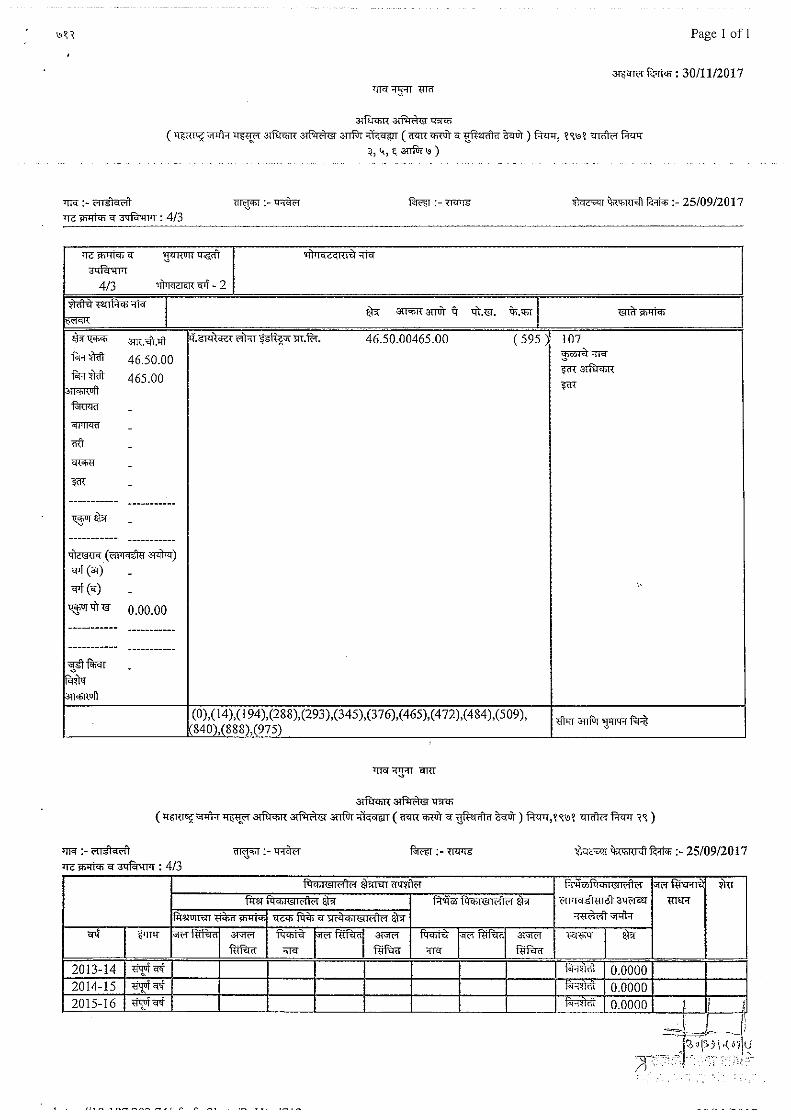
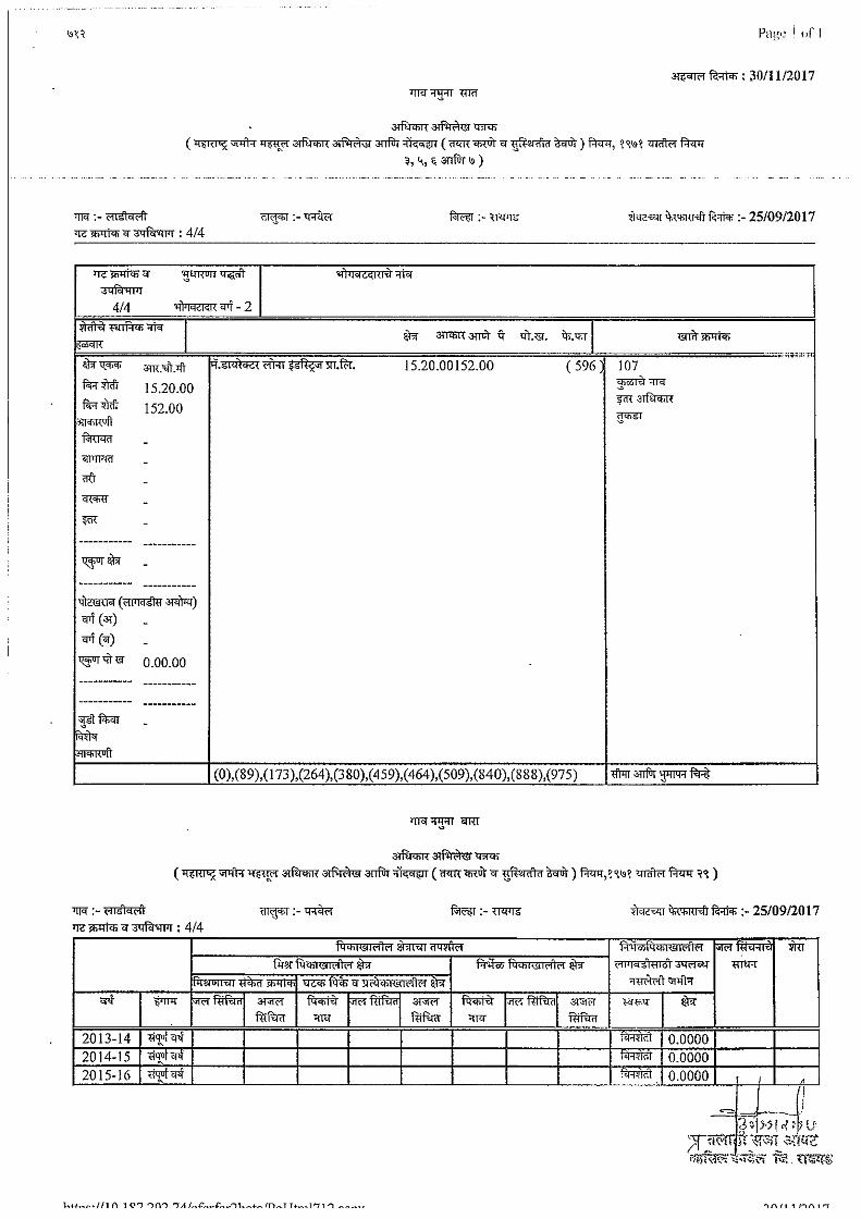
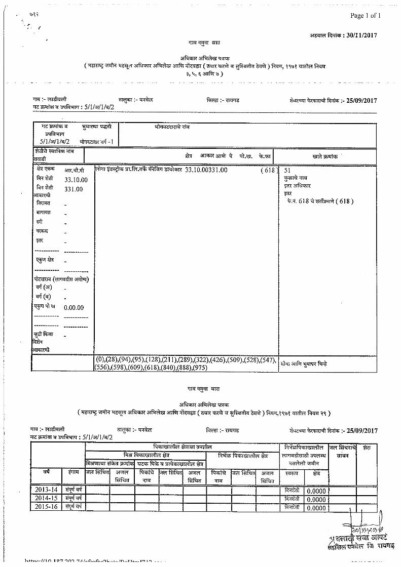
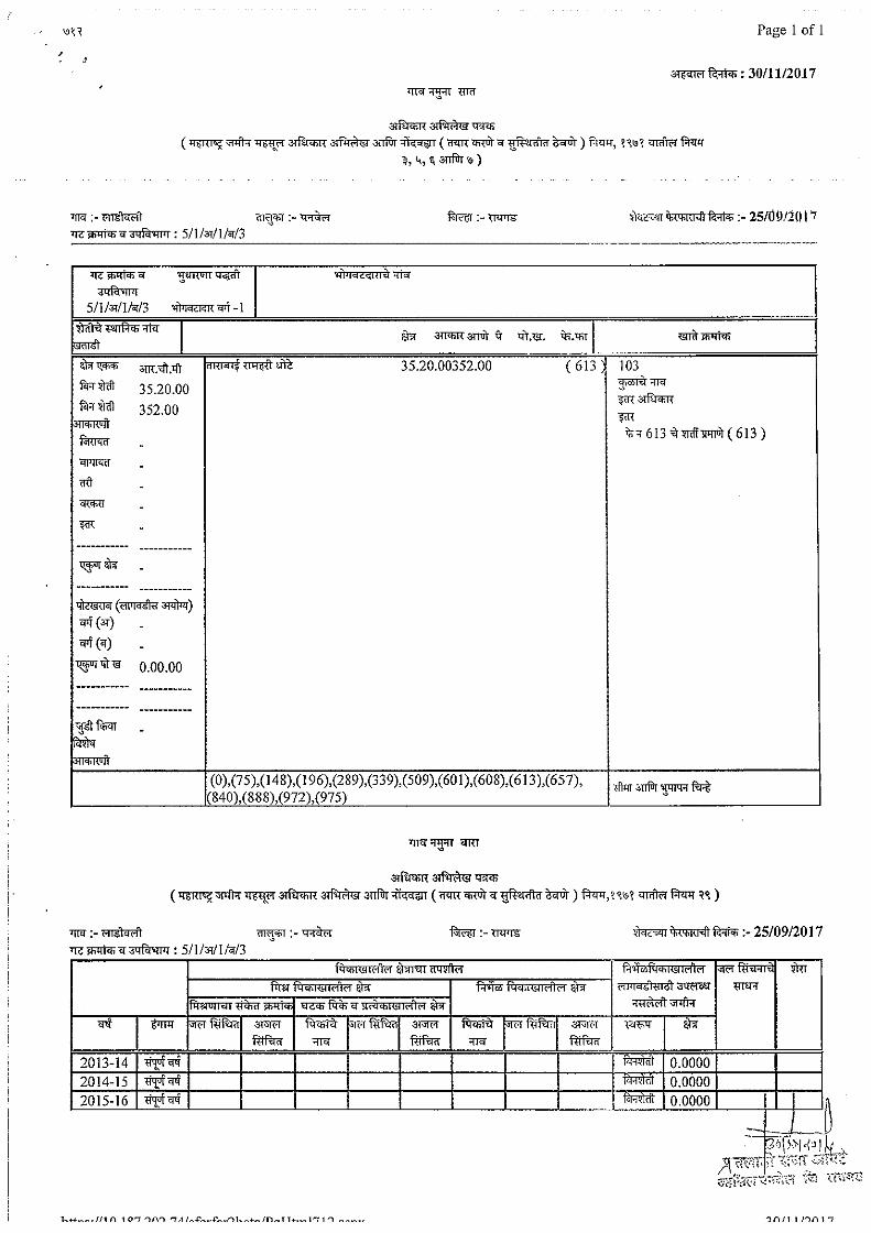
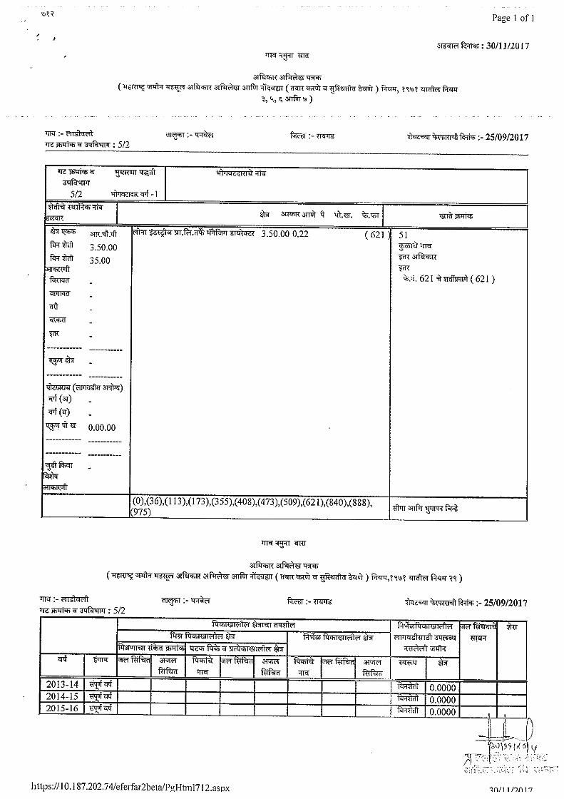
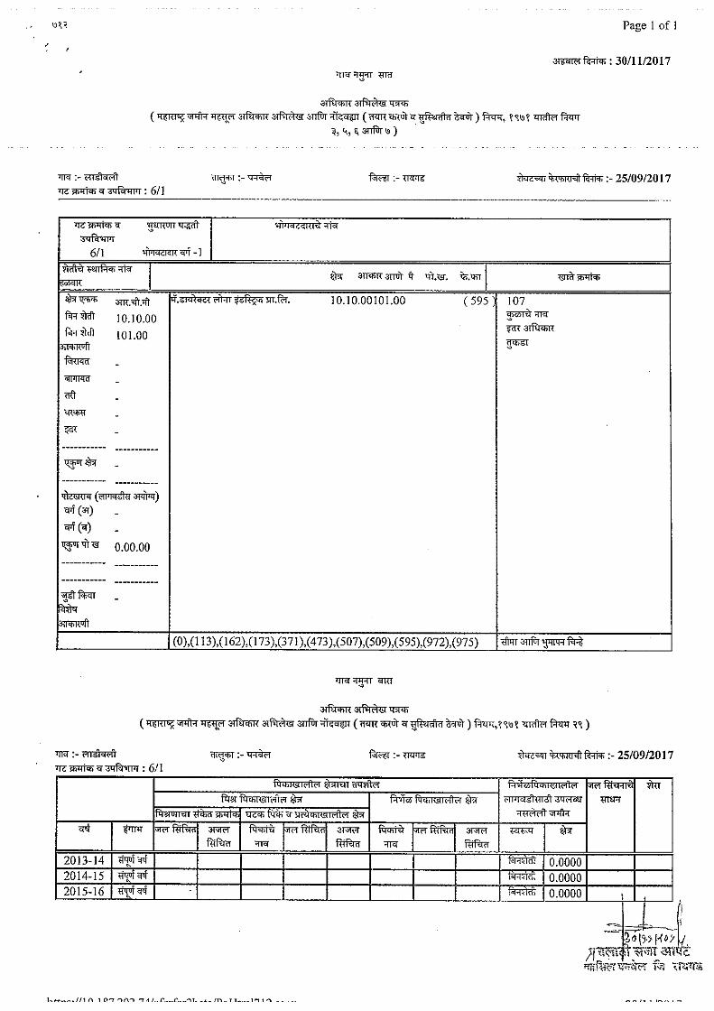
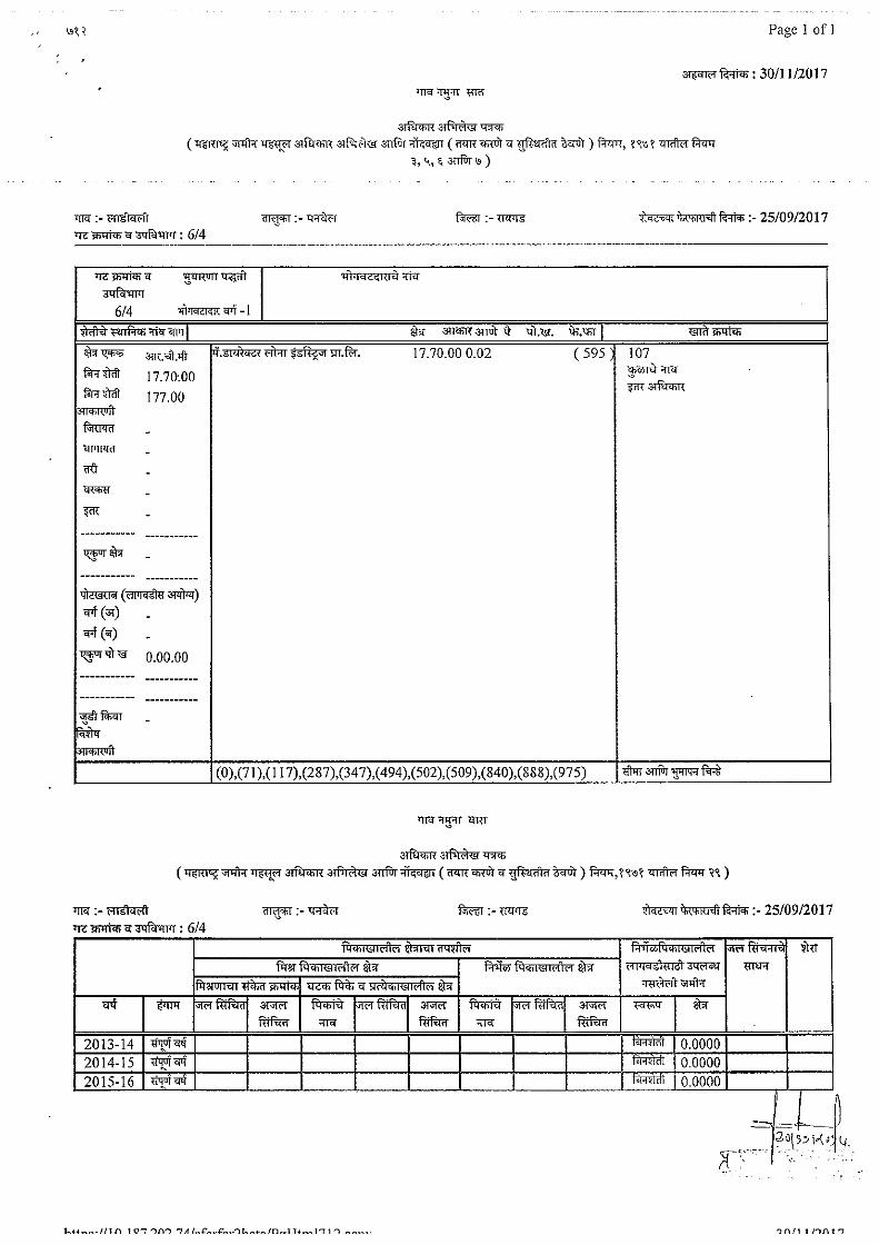
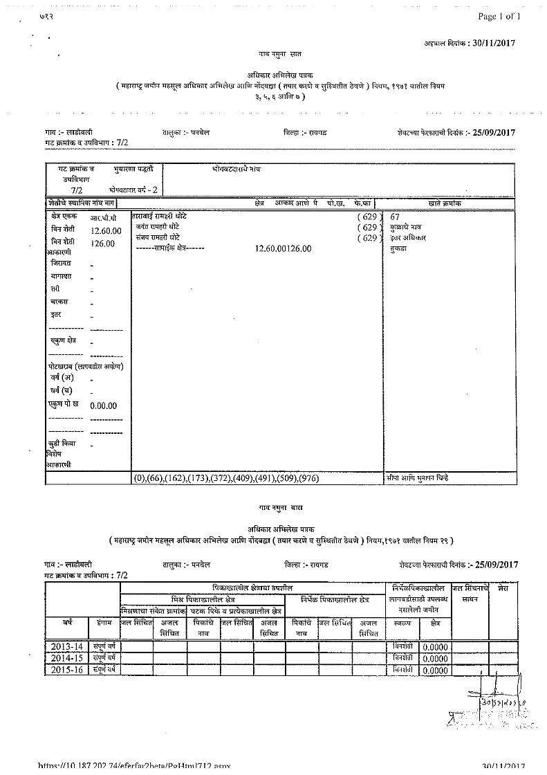
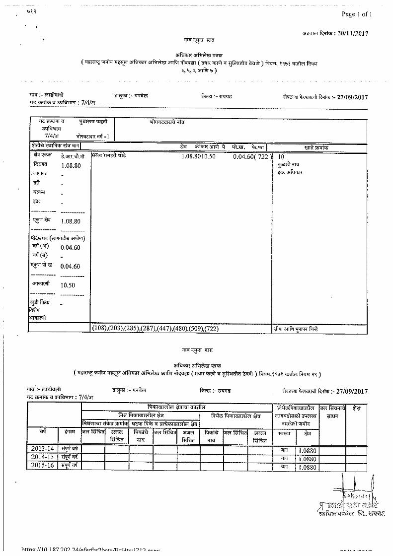
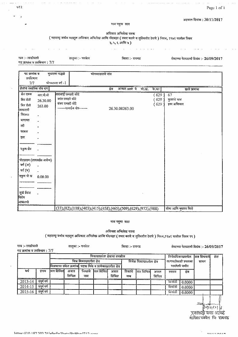
7/12 DETAILS