Embed Size (px)
Citation preview
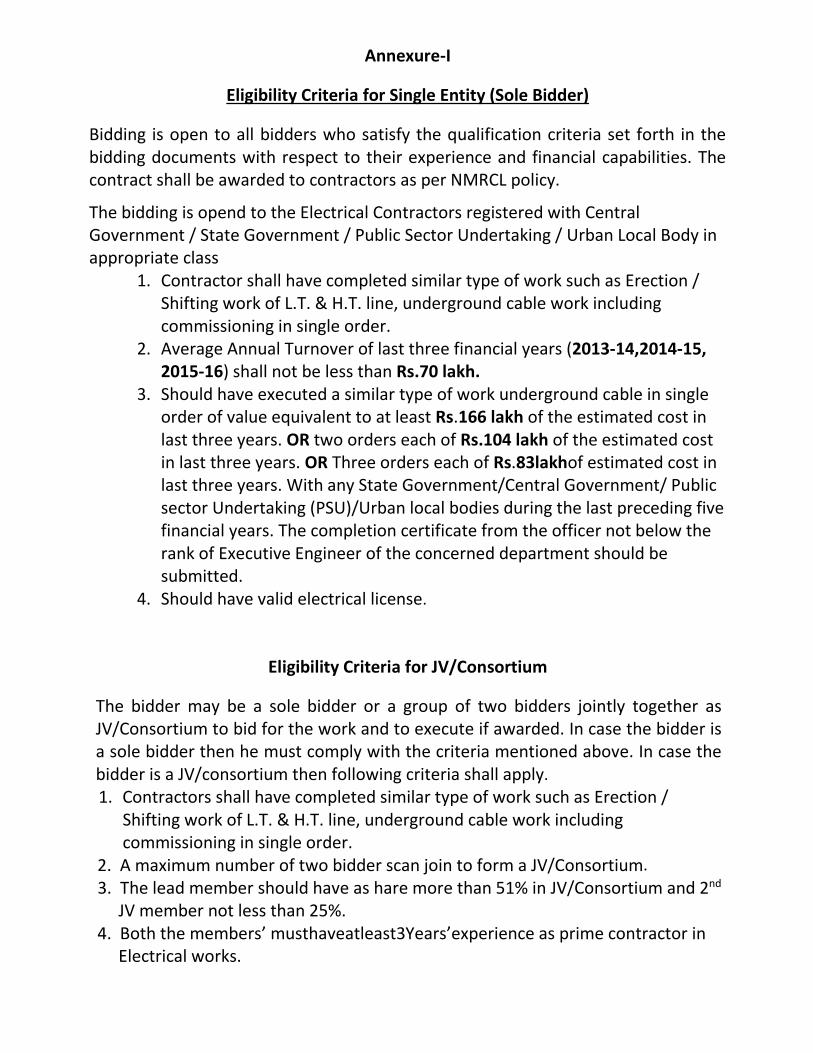
Annexure-I
Eligibility Criteria for Single Entity (Sole Bidder)
Bidding is open to all bidders who satisfy the qualification criteria set forth in the bidding documents with respect to their experience and financial capabilities. The contract shall be awarded to contractors as per NMRCL policy.
The bidding is opend to the Electrical Contractors registered with Central Government / State Government / Public Sector Undertaking / Urban Local Body in appropriate class
1. Contractor shall have completed similar type of work such as Erection / Shifting work of L.T. & H.T. line, underground cable work including commissioning in single order.
2. Average Annual Turnover of last three financial years (2013-14,2014-15, 2015-16) shall not be less than Rs.70 lakh.
3. Should have executed a similar type of work underground cable in single order of value equivalent to at least Rs.166 lakh of the estimated cost in last three years. OR two orders each of Rs.104 lakh of the estimated cost in last three years. OR Three orders each of Rs.83lakhof estimated cost in last three years. With any State Government/Central Government/ Public sector Undertaking (PSU)/Urban local bodies during the last preceding five financial years. The completion certificate from the officer not below the rank of Executive Engineer of the concerned department should be submitted.
4. Should have valid electrical license.
Eligibility Criteria for JV/Consortium
The bidder may be a sole bidder or a group of two bidders jointly together as JV/Consortium to bid for the work and to execute if awarded. In case the bidder is a sole bidder then he must comply with the criteria mentioned above. In case the bidder is a JV/consortium then following criteria shall apply.
1. Contractors shall have completed similar type of work such as Erection / Shifting work of L.T. & H.T. line, underground cable work including commissioning in single order. 2. A maximum number of two bidder scan join to form a JV/Consortium. 3. The lead member should have as hare more than 51% in JV/Consortium and 2nd JV member not less than 25%. 4. Both the members’ musthaveatleast3Years’experience as prime contractor in Electrical works.
2
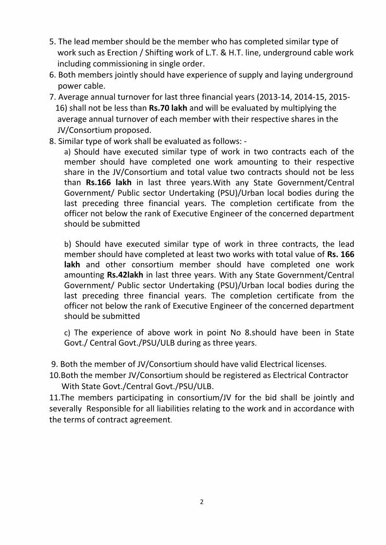
5. The lead member should be the member who has completed similar type of work such as Erection / Shifting work of L.T. & H.T. line, underground cable work including commissioning in single order. 6. Both members jointly should have experience of supply and laying underground
power cable. 7. Average annual turnover for last three financial years (2013-14, 2014-15, 2015- 16) shall not be less than Rs.70 lakh and will be evaluated by multiplying the average annual turnover of each member with their respective shares in the JV/Consortium proposed. 8. Similar type of work shall be evaluated as follows: -
a) Should have executed similar type of work in two contracts each of the member should have completed one work amounting to their respective share in the JV/Consortium and total value two contracts should not be less than Rs.166 lakh in last three years.With any State Government/Central Government/ Public sector Undertaking (PSU)/Urban local bodies during the last preceding three financial years. The completion certificate from the officer not below the rank of Executive Engineer of the concerned department should be submitted
b) Should have executed similar type of work in three contracts, the lead member should have completed at least two works with total value of Rs. 166 lakh and other consortium member should have completed one work amounting Rs.42lakh in last three years. With any State Government/Central Government/ Public sector Undertaking (PSU)/Urban local bodies during the last preceding three financial years. The completion certificate from the officer not below the rank of Executive Engineer of the concerned department should be submitted
c) The experience of above work in point No 8.should have been in State Govt./ Central Govt./PSU/ULB during as three years.
9. Both the member of JV/Consortium should have valid Electrical licenses.
10.Both the member JV/Consortium should be registered as Electrical Contractor With State Govt./Central Govt./PSU/ULB. 11.The members participating in consortium/JV for the bid shall be jointly and severally Responsible for all liabilities relating to the work and in accordance with the terms of contract agreement.

3
Annexure-II
SCHEDULE- B
Sr. No.
DSR Description Qty. Unit Rate Amount
1 7.3.13
Supplying , erecting & terminating 3 x 300 sq mm 11 KV, XLPE(E) round armoured cable to be laid in trench / pipe in an approved manner as per specification No CB-HT or latest.
1940 Mtr. 2110.00 4093400.00
2 MSEDCL
specification
Supplying , erecting & terminating 3 x 300 sq mm 33 KV, XLPE(E) round armoured cable to be laid in trench / pipe in an approved manner as per specification No CB-HT or latest.
2095 Mtr. 3540.00 7416300.00
3 7.1.29
Supplying, erecting & terminating PVC armoured cable 3½ core 185 sq mm aluminum conductor with continuous 12.97 sq mm (8 SWG) G.I. earth wire complete with glands & lugs, on pole or laid in trench/ pipe as per specification no. CB-LT/AL or latest.
352 Mtr. 1061.00 373472.00
4 5.2.15
Supplying and erecting mini feeder pillar triple pole with 300A FPMCCB as incomer and 3 outgoing circuits with HRC Fuse base and Cartridge of 100A consisting of aluminium bus bar 500V 300A complete erected in 14 gauge CRCA sheet box with supporting angles, self locks, gasket and slanting top to be erected on foundation as per specification No. SW-SWR/MFP
30 Each 48487.00 1454610.00
5 16.3.4
Providing Cement concrete foundation for panel in 1:2:4 with required size and length of foundation (cost with wooden box is included).
70.1 Cu.Mtr 5673.00 397677.30
6 8.8.3
Dismantling of existing overhead line including G.I. wires of all sizes without damaging & making the coils in suitable sizes and transporting to MSEDCL depot/ store.
3.275 Km 816.00 2672.40
7 7.5.16
Supplying ,providing and erecting Heat shrinkable outdoor termination kit for 11 KV XLPE HT cable 3x240 to 300 sq. mm. with necessary material as per specification No. CB-JT/HT or latest.
6 Each 15127.00 90762.00
4
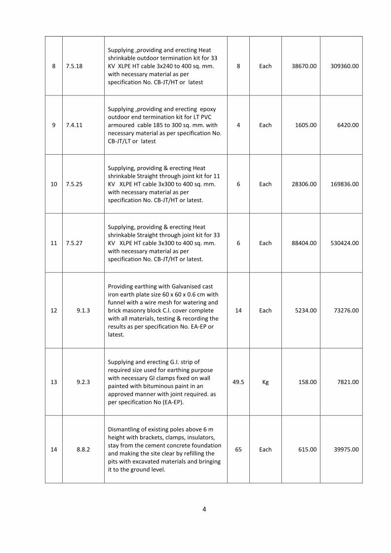
8 7.5.18
Supplying ,providing and erecting Heat shrinkable outdoor termination kit for 33 KV XLPE HT cable 3x240 to 400 sq. mm. with necessary material as per specification No. CB-JT/HT or latest
8 Each 38670.00 309360.00
9 7.4.11
Supplying ,providing and erecting epoxy outdoor end termination kit for LT PVC armoured cable 185 to 300 sq. mm. with necessary material as per specification No. CB-JT/LT or latest
4 Each 1605.00 6420.00
10 7.5.25
Supplying, providing & erecting Heat shrinkable Straight through joint kit for 11 KV XLPE HT cable 3x300 to 400 sq. mm. with necessary material as per specification No. CB-JT/HT or latest.
6 Each 28306.00 169836.00
11 7.5.27
Supplying, providing & erecting Heat shrinkable Straight through joint kit for 33 KV XLPE HT cable 3x300 to 400 sq. mm. with necessary material as per specification No. CB-JT/HT or latest.
6 Each 88404.00 530424.00
12 9.1.3
Providing earthing with Galvanised cast iron earth plate size 60 x 60 x 0.6 cm with funnel with a wire mesh for watering and brick masonry block C.l. cover complete with all materials, testing & recording the results as per specification No. EA-EP or latest.
14 Each 5234.00 73276.00
13 9.2.3
Supplying and erecting G.I. strip of required size used for earthing purpose with necessary GI clamps fixed on wall painted with bituminous paint in an approved manner with joint required. as per specification No (EA-EP).
49.5 Kg 158.00 7821.00
14 8.8.2
Dismantling of existing poles above 6 m height with brackets, clamps, insulators, stay from the cement concrete foundation and making the site clear by refilling the pits with excavated materials and bringing it to the ground level.
65 Each 615.00 39975.00
5
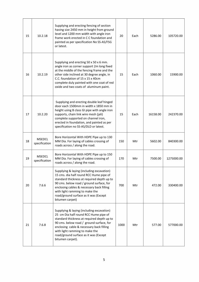
15 10.2.18
Supplying and erecting fencing of section having size 2450 mm in height from ground level and 1200 mm width with angle iron frame work erected in C C foundation and painted as per specification No SS-AS/FSG or latest.
20 Each 5286.00 105720.00
16 10.2.19
Supplying and erecting 50 x 50 x 6 mm. angle iron as corner support 2m long fixed at the middle of the fencing frame and the other side inclined at 30 degree angle, in C.C. foundation of 15 x 15 x 40cm complete duly painted with one coat of red oxide and two coats of aluminum paint.
15 Each 1060.00 15900.00
17 10.2.20
Supplying and erecting double leaf hinged door each 1500mm in width x 1850 mm in height using B class GI pipe with angle iron supports, chain link wire mesh (jali) complete supported on channel iron, erected in foundation, and painted as per specification no SS-AS/DLD or latest.
15 Each 16158.00 242370.00
18 MSEDCL
specification
Bore Horizontal With HDPE Pipe up to 130 MM Dia. For laying of cables crossing of roads across / along the road.
150 Mtr 5602.00 840300.00
19 MSEDCL
specification
Bore Horizontal With HDPE Pipe up to 150 MM Dia. For laying of cables crossing of roads across / along the road.
170 Mtr 7500.00 1275000.00
20 7.6.6
Supplying & laying (including excavation) 15 cms. dia half round RCC Hume pipe of standard thickness at required depth up to 90 cms. below road / ground surface, for enclosing cables & necessary back filling with light ramming to make the road/ground surface as it was (Except bitumen carpet)
700 Mtr 472.00 330400.00
21 7.6.8
Supplying & laying (including excavation) 25 cm Dia half round RCC Hume pipe of standard thickness at required depth up to 90 cms. below road / ground surface, for enclosing cable & necessary back filling with light ramming to make the road/ground surface as it was (Except bitumen carpet).
1000 Mtr 577.00 577000.00
6
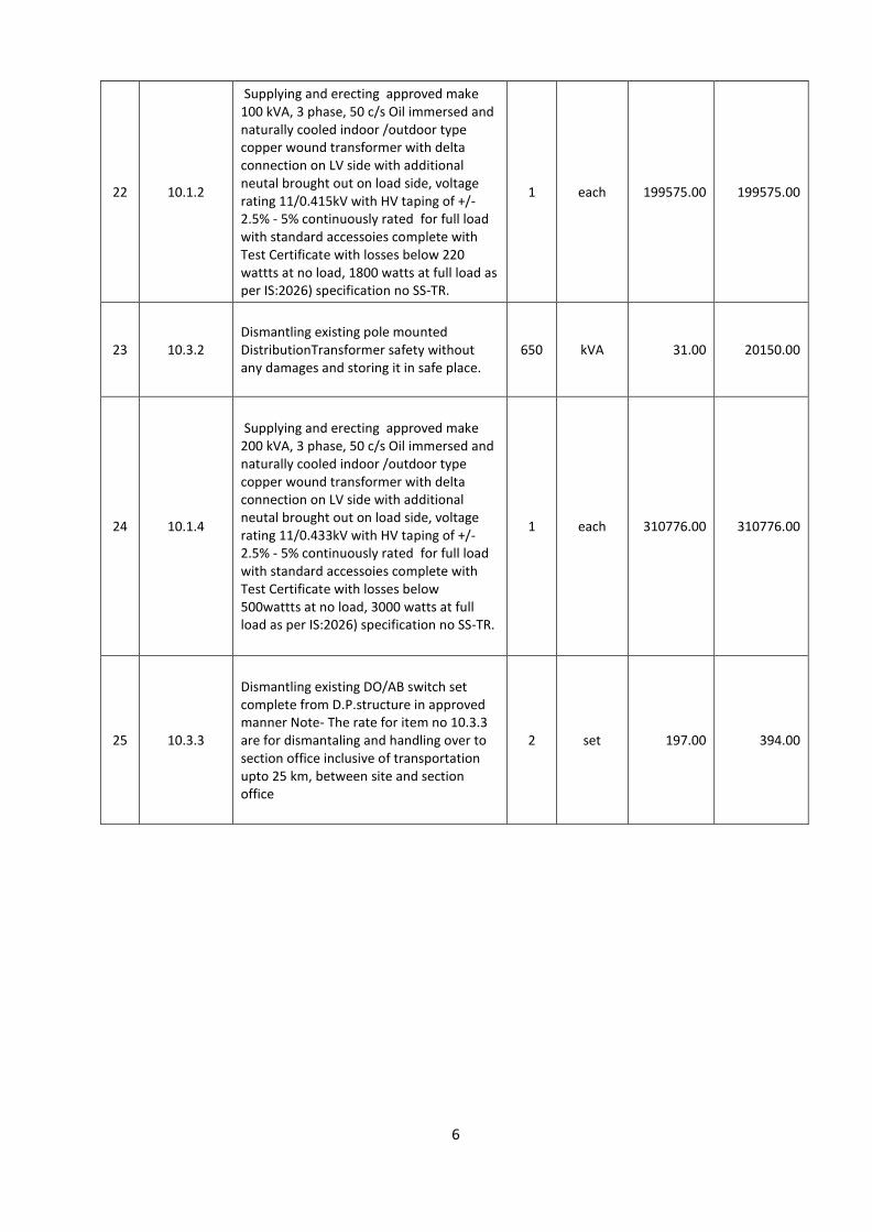
22 10.1.2
Supplying and erecting approved make 100 kVA, 3 phase, 50 c/s Oil immersed and naturally cooled indoor /outdoor type copper wound transformer with delta connection on LV side with additional neutal brought out on load side, voltage rating 11/0.415kV with HV taping of +/- 2.5% - 5% continuously rated for full load with standard accessoies complete with Test Certificate with losses below 220 wattts at no load, 1800 watts at full load as per IS:2026) specification no SS-TR.
1 each 199575.00 199575.00
23 10.3.2 Dismantling existing pole mounted DistributionTransformer safety without any damages and storing it in safe place.
650 kVA 31.00 20150.00
24 10.1.4
Supplying and erecting approved make 200 kVA, 3 phase, 50 c/s Oil immersed and naturally cooled indoor /outdoor type copper wound transformer with delta connection on LV side with additional neutal brought out on load side, voltage rating 11/0.433kV with HV taping of +/- 2.5% - 5% continuously rated for full load with standard accessoies complete with Test Certificate with losses below 500wattts at no load, 3000 watts at full load as per IS:2026) specification no SS-TR.
1 each 310776.00 310776.00
25 10.3.3
Dismantling existing DO/AB switch set complete from D.P.structure in approved manner Note- The rate for item no 10.3.3 are for dismantaling and handling over to section office inclusive of transportation upto 25 km, between site and section office
2 set 197.00 394.00

7
26 8.4.25
Supplying & erecting end pole D.P.structure for 100kVA Transformer with R.S.J. Pole 2Nos. Of size 100 * 116 mm * 11 Mtr. Long with suitable distribution box of C.R.C.A. sheet 16 SWG (size 4 SqMtr.) with 4 pole MCCB 100 Amps kitkat for outing ckts.Transformer D.P.structure inclludes the A.B. switch 200 Amps. D.O. fuse set & L.A. set 2 Nos. top channel of size 100mm *50mm for erection of A.B. switch & 2 nos. of base channelof size 100mm * 50mm for erecting transformer. Channel of size 75 * 40 mm for erecting D.O. fue set, L.A. , A.B. switch handle etc. Angle of size 50*50*6 mm for ereecting Distribution box, Transformer belt, etc. as per drawing (App. 124 Kg. iron work )with necessary clamps, nut-bolts. Vee cross arm, top clip, insulators etc. complete with caution board & barbed wire. D.P. sytructure shall be erected in provided cc foundation.
1 Each 125024.00 125024.00
27 MSEDCL
specification
Supplying & erecting 11 KV outdoor type Ring Main with scada cmpatible, motorised operation, without FRTU, Gas insulated & touch proof kit (if required), as per latest MSEDCL approval & speicifications with following configuration complete on CC foundation/MS channels/trench, etc, in an approved manner.
0.00
i 11KV 4nos. LBS + 1no. VCB 1 set 1150000.00 1150000.00
28 16.5.15
Supplying and erecting ISI mark G.I. pipe 100 mm dia ‘C” class position with accessories. As per specification No. CW-PLB/GP or latest.
30 Mtr 1821.00 54630.00
29 8.4.26
Supplying & erecting end pole D.P.structure for 200kVA Transformer with R.S.J. Pole 2Nos. Of size 100 * 116 mm * 11 Mtr. Long with suitable distribution box of C.R.C.A. sheet 16 SWG (size 4 SqMtr.) with 4 pole MCCB 100 Amps kitkat for outing ckts.Transformer D.P.structure inclludes the A.B. switch 200 Amps. D.O. fuse set & L.A. set 2 Nos. top channel of size 100mm *50mm for erection of A.B. switch & 2 nos. of base channelof size 100mm * 50mm for erecting transformer. Channel of size 75 * 40 mm for erecting D.O. fue set, L.A. , A.B. switch handle etc. Angle of size 50*50*6 mm for ereecting Distribution box, Transformer belt, etc. as per drawing (App. 124 Kg. iron work )with necessary clamps, nut-bolts. Vee cross arm, top clip, insulators etc. complete with caution board & barbed wire. D.P. sytructure shall be erected in provided cc foundation.
1 Each 131345.00 131345.00
8
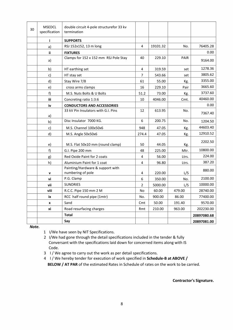
30 MSEDCL
specification double circuit 4-pole structurefor 33 kv termination
i SUPPORTS
a) RSJ 152x152, 13 m long 4 19101.32 No. 76405.28
ii FIXTURES 0.00
a)
Clamps for 152 x 152 mm RSJ Pole Stay 40 229.10 PAIR 9164.00
b) HT earthing set 4 319.59 set 1278.36
c) HT stay set 7 543.66 set 3805.62
d) Stay Wire 7/8 61 55.00 Kg. 3355.00
e) cross arms clamps 16 229.10 Pair 3665.60
f) M.S. Nuts Bolts & U Bolts 51.2 73.00 Kg. 3737.60
iii Concreting ratio 1:3:6 10 4046.00 Cmt. 40460.00
iv CONDUCTORS AND ACCESSORIES 0.00
a)
33 kV Pin Insulators with G.I. Pins 12 613.95 No. 7367.40
b) Disc Insulator 7000 KG. 6 200.75 No. 1204.50
c) M.S. Channel 100x50x6 948 47.05 Kg. 44603.40
d) M.S. Angle 50x50x6 274.4 47.05 Kg. 12910.52
e) M.S. Flat 50x10 mm (round clamp) 50 44.05 Kg. 2202.50
f) G.I. Pipe 200 mm 48 225.00 Mtr. 10800.00
g) Red Oxide Paint for 2 coats 4 56.00 Ltrs. 224.00
h) Aluminium Paint for 1 coat 4 96.80 Ltrs. 387.20
v
Painting/Hardware & support with numbering of pole 4 220.00 L/S
880.00
vi P.G. Clamp 6 350.00 No. 2100.00
vii SUNDRIES 2 5000.00 L/S 10000.00
viii R.C.C. Pipe 150 mm 2 M No 60.00 479.00 28740.00
ix RCC half round pipe (1mtr) No. 900.00 86.00 77400.00
x Sand Cmt 50.00 191.40 9570.00
xi Road resurfacing charges Rmt 210.00 963.00 202230.00
Total 20897080.68
Say 20897081.00
Note. 1 I/We have seen by NIT Specifications. 2 I/We had gone through the detail specifications included in the tender & fully Conversant with the specifications laid down for concerned items along with IS Code. 3 I / We agree to carry out the work as per detail specifications. 4 I / We hereby tender for execution of work specified in Schedule-B at ABOVE /
BELOW / AT PAR of the estimated Rates in Schedule of rates on the work to be carried.
Contractor's Signature.

9
Annexure-III
ADDITIONAL SPECIFICATION / CONDITION
1) Arrangement for the curing of C, C, foundation muffing, brick masonry work etc. shall be done
by clean and soft water at site by the contractor at his own cost.
2) While executing the E.I. work, the agency shall provide Generator for Electrical Drill machine at
his own cost.
3) The Agency shall follow the ISI specification, relevant standards, IER 1956 during the execution of work.
4) The agency shall obtain the permission of local Authority (N.O.C.) for digging the road if necessary.
5) If during the execution of work, shut down form M.S.E.D.C.L./ SPANCO. Side is necessary. In
that case it is solely responsibility of agency to take necessary shut down with permission of local MSEDCL/SPENCO authority.
6) The agency will have to use necessary T&P while execution of work at his own cost.
7) After completion of work, the Agency shall have to carry necessary I R test and earth Test
with calibrated meggar & earth tester and the test report of same shall be submitted.
8) The agency shall have to arrange the approval & inspection of E.I. from Electrical Inspector
and accordingly N.O.C. shall be obtained however the necessary inspection fee will be borne by NMRCL. Also necessary testing charges of M.S.E.D.C.L./SPENCO shall be paid by the agency.
9) The work insurance and insurance of worker Labour insurance shall be done by agency under
the insurance act of his own cost.
10) The complete responsibility of safety of worker during the execution of work is solely of agency. The agency will have to follow all the safety rules during the execution of work. If any accident occurred during the execution of work, the responsibility of compensation will be of agency. In any case, this NMRCL will not be responsible for any compensation.
11) Any fees/charges/taxes or penalties towards payment of Government/Semi- Government/Local /Private Bodies arising during the execution of the work is to be borne by the agency. No compensation or refunds will be paid for this.
12) Necessary approval for the material procurement shall be obtained by the contractor from the
authority before starting the work.
13) The actual layout drawing shall be got approved by the contractor from the concern Electrical Inspector before starting the work.
14) The permission for charging the installation shall be obtained by the contractor from the
concern Electrical Inspector after completion of the work.
15) The dismantled materials i.e. brackets clamps5 insulators, stay sets, A.B. switch Lightning
Arrestors, G.I. Wire & ACSR conductors RSJ poles Transformer shall be

2
handed over to NMRCL at Suitable Stores as directed by Engineer –in-charge and copy of receipt of handing over shall be submitted .This include lead and lift.
16) Contractor has to take prior permission from MSEDCL/ SPANCO /NMC and any concerned
authority for shifting of electrical services and it’s shut down.
17) The High Pot test of 11 KV cable shall be arrange by the agency at site after laying the cable in
presence of the concerned Engineer of the NMRCL . The cost will be borne by the agency.
3
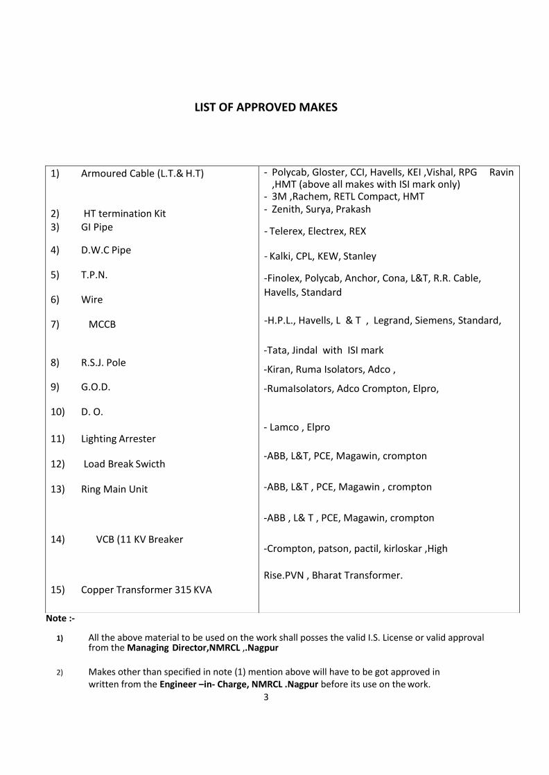
LIST OF APPROVED MAKES
Note :-
1) All the above material to be used on the work shall posses the valid I.S. License or valid approval from the Managing Director,NMRCL ,.Nagpur
2) Makes other than specified in note (1) mention above will have to be got approved in
written from the Engineer –in- Charge, NMRCL .Nagpur before its use on the work.
1) Armoured Cable (L.T.& H.T)
2) HT termination Kit 3) GI Pipe
4) D.W.C Pipe
5) T.P.N.
6) Wire
7) MCCB
8) R.S.J. Pole
9) G.O.D.
10) D. O.
11) Lighting Arrester
12) Load Break Swicth
13) Ring Main Unit
14) VCB (11 KV Breaker
15) Copper Transformer 315 KVA
- Polycab, Gloster, CCI, Havells, KEI ,Vishal, RPG Ravin ,HMT (above all makes with ISI mark only)
- 3M ,Rachem, RETL Compact, HMT - Zenith, Surya, Prakash
- Telerex, Electrex, REX
- Kalki, CPL, KEW, Stanley
-Finolex, Polycab, Anchor, Cona, L&T, R.R. Cable,
Havells, Standard
-H.P.L., Havells, L & T , Legrand, Siemens, Standard,
-Tata, Jindal with ISI mark
-Kiran, Ruma Isolators, Adco ,
-RumaIsolators, Adco Crompton, Elpro,
- Lamco , Elpro
-ABB, L&T, PCE, Magawin, crompton
-ABB, L&T , PCE, Magawin , crompton
-ABB , L& T , PCE, Magawin, crompton
-Crompton, patson, pactil, kirloskar ,High
Rise.PVN , Bharat Transformer.
4
3) The Material brought at the site shall be ISI make And mark duly approved in written by
Engineer –in- Charge of NMRCL
4) Samples of material during the execution of work will be collected and sent to testing if the testing results of material found unsatisfactory in that case the agency will have to replace the material free of
5
NAGPUR METRO RAIL CORPORATION LIMITED
Name of Work:- Shifting of LT,HT O/H line ,crossings and providing LT,HT U/G cables from
Lad square (CH:10750) to Munje Chowk (CH:7743) for Nagpur Metro Rail Project for E-Corridor.
DETAILED SPECIFICATION
Sr. No. CSR Item No Specification
1-4-2 The work shall be carried out as per wording of the item and as directed
by Engineer in-charge.
1-4-3The work shall be carried out as per wording of the item and as directed by Engineer in-
charge
1-4-7The work shall be carried out as per wording of the item and as directed by Engineer
in-charge.
5-5-35.5 Moulded Case Circuit Breaker (MCCB)
Scope Specification No (SW-SWR/MCCB) Providing & erecting 3 Pole/4 Pole MCCB of specified rating and with specified short circuit rupturing capacity in KA, complete erecting in provided enclosure & connected with provided leads on incoming and outgoing side, complete. General Specifications for MCCB's MCCB's should comply with IS 13947.part -2, IEC (6094) and IEC 60947-3 & IEC 60947 part2. The MCCB shall be suitable for universal mounting i.e. the load/line shall be interchangeable with shrouded incoming contacts. The MCCB shall be suitable for minimum operating voltage of 415 V. The thermal setting shall be adjustable from 64 % to 100% of i»s normal current The magnetic setting shall be adjustable from 3.5 to 10 In (normal current). Trip reset should be available Manual / Automatic. Isolator switches for electronic circuits to open the MCCB automatically. The MCCB*s must house transparent label holder to ensure circuit identification. The MCCB's must have fully insulated safety shutters. Overload Zone adjustable from 0.4 to 1 in with line (For 630 amp & above MCCB) Short circuit Zone adjustable from 1.5 to 10 In with time. Material: 3 pole or 4 Pole MCCB Moulded case circuit breaker. Fixed version front Terminals with current rating & breaking capacity as below:
6
i. 63 A to 125 A - 15 KA ii. 160 A to 250 A - 35 KA iii. 300/400 A - 35 KA iv. 630 A - 70 KA
Method of Construction: 3 pole /4 pole MCCB shall be erected in provided enclosure & connected with provided leads/strip on incoming & out going site complete Mode of Measurement: Executed quantity shall be counted on number basis, (i.e. each) 5 5-10-10 The work shall be carried out as per wording of the item and as directed by Engineer n- charge.
6 5-10-24 The work shall be carried out as per wording of the item and as directed by 7 5-10-27 The work shall be carried out as per wording of the item and as directed by
8 6-1-2 The work shall be carried out as per wording of the item and as directed by 9 6-1-11 The work shall be carried out as per wording of the item and as directed by 10 6-1-16 The work shall be carried out as per wording of the item and as directed by
11 6-1-19 The work shall be carried out as per wording of the item and as directed by 12 6-1-20 The work shall be carried out as per wording of the item and as directed by 13 7-1 -21 Attached Separately 14 7-l-29 Attached Separately 15_ 7-3-12 Attached Separately" 16 7-5-1$ 7.4 & 7.5 Cable Joints & End Termination Kits (LT/HT Cables) (JT/LT/HT)
Specification No (CB-JT/LT/HT)
1. Scope:
Providing straight through cable jointing kit of approved make and jointing cable as per the manufacturer's instructions and duly marking name of jointer and date.
2. Material:
Joint kit: Kit manufactured by reputed manufacturer with PVC moulds made in two parts, with epoxy compound, earth continuity lead of appropriate cross section having lugs at both ends, aluminum ferrules of the size of the cable, cross shaped epoxy spacer, MS clips for holding the moulds, adhesive for pasting the moulds.
3. Method of Construction:
Straight through joint Kit: LTVHT Cables
Before providing joint to the cable, the cable ends of the equivalent length of the joint moulds, shall be prepared By removing the outer PVC insulation along with the steel armouring. The ferrule shall then be inserted over the bare core of the cable, and shall be crimped with hydraulic / mechanical type heavy duty crimping tool. The crimped portion shall be wrapped first with the PVC insulation tape and then with the insulation tape used for wrapping HT conductor. The above method shall be carried out for all the cores strictly following the colour code. The leads of the both the cables now shall be placed into the mould by using the epoxy spacers for having sufficient
7
gap in-between the leads. The earth continuity lead shall be clamped to the both ends of the cable. After covering the cable leads with the PVC moulds, the edges shall be clipped after applying the adhesive on the inside face of the moulds. The pasting of moulds shall be rigid and as far as possible leak proof, so that the epoxy compound shall not spill out. Now the duly stirred epoxy compound shall be poured and fill till the compound rises through the risers provided on the moulds.
After completing the above procedure," the joint shall be allowed to dry out for at least 8 to 10 hours (for epox compound to get hardened) depending upon the size of cable. Before connecting to supply, the dry and hardened joint shall be tested for its insulation level with 1000 VI 5000 V Meggar.
The cable should be fixed or laid in such manner that there should not be pressure on end of moulds or on jointing position of cables. (Refer drawing No. CB-JT-1)
3.2 Outdoor/Indoor end termination Kit: LT/HT Cables
Before providing end termination Id! to the cable, the cable end of the equivalent length of the moulds, shall be prepared by removing the outer PVC insulation along with the steel armouring. The ferrule shall then be inserted over the bare core of the cable, and shall be crimped with hydraulic / mechanical type heavy duty crimping tool. The crimping shall be done in such a manner that there shall be no air gap. Then the crimped portion shall be wrapped first with the PVC insulation tape and then with the insulation tape used for wrapping HT conductor. The above method shall be carried out for all the cores strictly following the colour code. The leads of the cable now shall be placed into the mould by using the epoxy spacer, for having sufficient gap in-between the leads.
The earth continuity lead shall be clamped to intends of the cable. After covering
the cable leads with the PVC moulds, the edges shall be clipped after applying the adhesive on the inside face of the moulds. The pasting of moulds shall be rigid and as far as possible leak proof, so that the epoxy compound shall not spill out Now the duly stirred epoxy compound shall be poured and fill till the compound rises through the risers provided on the moulds. (Refer drawing No. CB-JT-2)
After completing the above procedure, the joint shall be allowed to dry out for at least 8 to 10 hours (for epoxy compound to get hardened) depending upon the size of cable. Before connecting to supply, the dry and hardened joint shall be tested for its insulation level with 1000 VI 5000 V Meggar. 4 Mode of Measurement: Executed quantity will be measured on number basis, (i.e. each).
7-6-5 The work shall be carried out as per wording of the item and as directed by
Engineer in-charge.
7-6-4 4.1.1 Erection of Pipe on wall: The required length of pipe shall be machine cut, without any sharp edges, burrs, etc. The pipe duly enclosing the specified material, shall be erected on wall in plum, and fixed with required size of MS clamps on wall with plugs, gitties, etc. When the pipe is to be fixed to walls it shall be fixed with standard bracket, clips or holder by keeping the pipe about i2mm clear of the wall. The pipe shall be fixed to the wall horizontally and vertically and parallel to one another, when more than one pipe is to be laid, unless unavoidable. The

8
supporting clips, etc. for the pipe shall be spaced at about two meters or so as necessary. Holes cut during construction shall not be left out; they shall be filled and finished after passing of the pipe through it.
4.1.2 Erection- of Pipe on pole: The required length of pipe shall be machine cut, without any sharp edges, burrs, etc. The pipe duly enclosing the specified material, shall be erected on pole in plum, and fixed with required size of MS clamps with MS nuts & bolts of required size and strength. When the pipe is to be used as cable enclosure and is to be terminated on street light pole(s), the pipe at the trench level should be placed at least 30 cm above the cable evel for avoiding damage to the insulation of cable.
5-5-1 5.5 Moulded Case Circuit Breaker (MCCB)(MCCB) Scope: Specification No (SW-SWR/MCCB)
Providing & erecting 3 Pole/4 Pole MCCB of specified rating and with specified short circuit rupturing capacity in KA, complete erecting in provided enclosure & connected with provided leads on incoming and outgoing side, complete.
Genera! Specifications for MCCB's MCCB's should comply with IS 13947 part -2,1EC (6094) and IEC 60947-3 & IEC 60947 part 2. The MCCB shall be suitable for universal mounting i.e. the load/line shall be interchangeable with shrouded incoming contacts. The MCCB shall be suitable for minimum operating voltage of 415 V. The thermal setting shall be adjustable from 64 % to 100% of its normal current. The magnetic setting shall be adjustable from 3.5 to 10 In (normal current). Trip reset should be available Manual / Automatic. Isolator switches for electronic circuits to open the MCCB automatically. The MCCB's must house transparent label holder to ensure circuit identification. The MCCB's must have fully insulated safety shutters. Overload Zone adjustable from 0.4 to I in with line (For 630 amp & above MCCB) Short circuit Zone adjustable from 1.5 to 10 In with time.
Material: 3 pole or 4 Pole MCCB Moulded case circuit breaker. Fixed version front Terminals with current rating & breaking capacity as below:
i. 63 A to 125 A - 15 KA ii 160 A to 250 A - 35 KA iii.300/400 A - 35 KA iv.630A - 70 KA
Method of Construction:
3 pole /4 pole MCCB shall be erected in provided enclosure & connected with provided leads/strip on incoming & out going site complete Mode of Measurement: Executed quantity shall be counted on number basis, (i.e. each) 20 8-1-10 Attached Separately
21 8-1-11 Attached Separately 22 8-4-1 Attached Separately 23 8-4-2 Attached Separately'
9
24 8-4-11 Attached Separately 25 8-4-12 B)D Vee Cross ArmaD(OH-PL/VCA)
G Scope: Specification No D(OH-PL/VCAl)a Supplying Vee cross arm, suitable for 11 kV and necessary ancillary materials complete erection on provided pole with necessary painting as per specification and as per the
instructions from the site engineer, Material: a) Cross arm: Channel Iron cross arm b) Hardware: G.I. nut bolts c) FIat: MS flat 80 x 10 mm thick d) Clamp; Two clamps made from MS flat of size 80 x10 mm. e) Paint: Red oxide. Silver paint.
Method of construction: Fabricating the Vee cross arm for erecting Insulators with channel 75 x 40 mm with the 4.4 mm
thick web and 7.3 mm thick flange, length of 45 mm for base of insulator, vertical member of suitable
length to maintain the clearance of 1220 mm, will angle of 600 degrees to horizontal and M.S. flat of 80 x 10 mm at centre of cross arm fixed to the pole by means of two A clamps of 80 x 10 mm. M.S. flat with 15mm. dia bolts and nuts Q duly painted with one coat of red oxide paint and two coa of aluminum paint. Cross arm same all be fabricated as per drawing no. OH-PL/BKT-l (Fig.l) Ci Detailed specifications of material of the items included in CSR are given in OTable No 8.4/2. Mode of Measurement: Executed quantity will be measured on number basis (i.e. Deach)
26 8-4-14 B) Vee Cross Arm OO(OH-PI7VCA)
Scope: Specification No D(OH-PL/VCA1)0
Supplying Vee cross arm, suitable for 11 kV and necessary ancillary materials Incomplete Defection on provided pole with necessary painting as per specification and as per Destructions from the site engineer. D Material: Cross arm: Channel Iron cross arm Hardware: G.I. nut bolts DFIat: MS flat 80 x 10 mm thick CIamp: Two clamps made from MS flat of size 80 x10mm.
Paint: Red oxide. Silver paint. Method of construction: Fabricating the Vee cross arm for .erecting Insulators with channel 75 x 40 mm with 4.4 mm thick web and 7.3 mm thick flange, length of 45 mm for base of insulator, vertical member of suitable length to maintain the clearance of 1220 mm, will angle of 60 degrees to horizontal and M.S. flat of 80 x JO mm at centre of cross arm fixed to the pole by means of two A clamps of 80 x 10 mm M.S. flat with 15mm. dia bolts and nuts duly painted with one coat of red oxide paint and two coa of aluminium paint. Cross arm shall be fabricated as per drawing no. OH-PL/BKT-l ( Fig. 1) Detailed specifications of material of the items included in CSR are given in Table No 8.4/2. Mode of Measurement: Executed quantity will be measured on number basis (i.e. each)
27 8-4-15 B) Vee Cross Arm a (OH-PlTVCA)
10
Scope: Specification No D(OH-PL/VCA1)D Supplying Vee cross arm, suitable ;"or 11 kV aAd necessary ancillary materials complete Direction on provided pole with necessary painting as per specification and as per Destructions from the site engineer.
Material:
Cross arm: Channel Iron cross arm Hardware: G.I. nut bolts Q FIat: MS flat 80 x 10 mm thick Clamp : Two clamps made from MS flat of size 80 x10mm. Paint: Red oxide. Silver paint.
Method of construction:
Fabricating the Vee cross arm for erecting Insulators with channel 75 x 40 mm with 4.4 mm thick web and 7.3 mm thick flange, length of 45 mm for base of insulator, G vertical member of suitable length to maintain the clearance of 1220 mm, with angle of 60 D degrees to horizontal and M.S. fiat of 80 x 10 mm at centre of cross arm fixed to the pole by means of two A clamps of 80 x 10 mm M.S. flat with 15mm. dia bolts and nuts duly painted with one coat of red oxide paint and two coat of aluminium paint. Cross arm shall be fabricated as per drawing no. OH-PL/BK.T-I
Detailed specifications of material of the items included in CSR are given in Table No 8.4/2. Mode of Measurement: Executed quantity will be measured on number basis (i.e. each)
28 8-5-2 8.5 Conductors (CON) A) All Aluminium Conductors (AAC)(OH- CON/AAC) ■ Scope: ■ Specification No {OH-C ON/AAC) ■ Supply and erection of All Aluminium Conductors for overhead line. ■Material: ■Conductor: All aluminium stranded conductor . (As
pertable8.5/1) ■ ■Binding wire: 12 SWG aluminium binding wire. ■Clamps: PG clamps as per requirement
Method of construction: At first the conductor is removed from bundle/drum straighten without knots, bends, etc. Stringing of conductor shall be done with draw vice. Conductor shall not be twisted while stringing. Shackle insulators sr be used if the line deviates by 30 degrees or more, at terminal pole and at junction/ cut pole.
Parallel double groove clamp having two nut bolts designated to carry full line current shall be used for making Jumper w connections.
On straight line the conductor shall be bounded on top groove of insulator and at angular position binding shall be done in side groove. Binding wire of 12 SWG shall be of the same metal as that of conductor.
Mode of Measurement: For measurement purpose, sum of the total conductor including jumper connections shall be considered, (i.e. per km)
11
29 8-5-5 8.5 Conductor (CON)
A)AI1 Aluminum Conductors (AAC)(OH-CON/AAC)
Scope: Specification No (OH-CON/AAC) Supply and erection of All Aluminum Conductors for overhead line. Material:
Conductor: All aluminum stranded conductor (As per table 8.5/1) (Binding wire: 12 SWG aluminum binding wire
Clamps: PG clamps as per requirement Method of construction:
At first the conductor is removed from bundle/drum straighten without knots, bends, etc. Stringing of conductor shall be done with draw vice. Conductor shall not be twisted while stringing. Shackle insulators shall be used if the line deviates by 30 degrees or more, at terminal pole and at junction/ cut pole.
Parallel double groove clamp having two nut bolts designated to carry full line current D shall be used for making Jumper connections.
On straight line the conductor shall be bounded on top groove of insulator and at angular position binding shall be done in side groove. Binding wire of 12 SWG shall be of the same metal as that of conductor. Mode of Measurement:
For measurement purpose, sum of the total conductor including jumper connections D shall be considered, (i.e. per km)
30 8-5-10 Attached Separately 31 8-5-12 The work shall be carried out as per wording of the item and as directed by
Engineer in-charge. Shall be carried out as per wording the 32 8-6-3 item and as directed by Engineer in-charge. 5.5 Molded Case Circuit 33 5-5-2 Breaker (MCCB) (MCCB)
Scope: Specification No (SW-SWR/MCCS) Providing & erecting 3 Pole/4 Pole MCCB of specified rating and with specified short circuit rupturing capacity in KA, complete erecting in provided enclosure & connected with provided leads on incoming and outgoing side, complete. General Specifications for MCCB's MCCB's should comply with IS 1 3947 part -2, IEC (6094) and !EC 60947-3 & IEC 60947part 2. The MCCB shall be suitable for universal mounting i.e. the load/line shall be interchangeable with shrouded incoming contacts.
"The MCCB shall be suitable for minimum operating voltage of4I5V. The thermal setting shall be adjustable from 64 %to 100% of its normal current. The magnetic setting shall be adjustable from 3.3 to 10 In (normal current). Trip reset should be available Manual / Automatic. Isolator switches for electronic circuits to open the MCCB automatically. The MCCB's must house transparent label holder to ensure circuit identification. The MCCB's must have fully insulated safety shutters. Overload Zone adjustable from 0.4 to 1 in with line (For 630 amps & above MCCB) Short circuit Zone adjustable from 1.5 to 10 In with time.
12
Material: 3 pole or 4 Pole MCCB Molded case circuit breaker. Fixed version front Terminals with current rating & breaking capacity as below:
i. 63 A to 125 A - 15KA ii 160 A to 250 A 35 KA
iii 300/400 A - 35 KA iv. 630 A - 70 KA
Method of Construction:
3 pole /4 pole MCCB shall be erected in provided enclosure & connected with provided leads/strip on incoming & out going site complete Mode of Measurement: Executed quantity shall be counted on number basis, (i.e. each)
34 8-6-6 8.6 Insulators (INS)
A) Porcelain Disc Type Insulator 11/22/33 kV DO(OH-!NS/DI)
Scope
Specification No (OH-INS/DI)
Supplying porcelain disc type insulator, suitable for 11/22/33KV and necessary Q ancillary materials and complete erection provided cross arm / bracket and connected to the over-head line as per instructions from the site engineer
Material:
Insulator: Distribution class Disc type insulator made from porcelain, suitable for specified voltage level, having 1Smark with necessary hardware. Hardware; Nuts, washers, etc. Binding wire: Bare Copper wire or conductor. C-lamps: MS clamps.
Method of construction: Distribution class porcelain disc type insulator, suitable for specified voltage level, erected on provided cross arm or Bracket with clamps, ancillary materials, and connected to the over-head line. Connection shall be made with bare copper wire of specified gauge.
Mode of Measurement: Executed quantity will be measured on number
basis (i.e. each) 8-6-9
B) PinType Insulator 11/22/33 kV(OH-INS/PN)
Scope:
Specification No {OH-INS/PN) Supplying porcelain Pin type insulator, suitable for 11/22/33KV and necessary ancillary
materials and complete erection . Provided cross arm / bracket and D connected to the over-
13
head line as per instructions from the site engineer Material: insulator: Distribution class Pin
type insulator made from porcelain, suitable for d specified voltage level, having ISI mark, with
necessary hardware. Hard ware: Nuts, washers, etc. Binding wire: Bare Copper wire or
conductor. Iamps: MS clamps.
Method of construction;
Distribution class porcelain pin type insulator suitable for specified voltage level, a erected on provided cross arm or bracket with clamps, ancillary materials, and D connected to the over-head line. Connection shall be made with bare copper wire of specified gauge. Mode of Measurement: Executed quantity will be measured on number basis (i.e. each)
Thyrite type Lightening Arrester 11/22 kV (OH-
INS/LA) Scope:
Specification No (OH-INS/LA)
Supplying porcelain Thy rite type lightening arrester, suitable for specified voltage level and
necessary ancillary materials and complete erection on provided cross arm / bracket and
connected to the over-head line as per instructions from the engineer.
Material:
Arrestor: Distribution class Thy rite type lightening arrestor made from porcelain, suitable for specified voltage level, have ISI mark.
Hardware: Nuts, washers, etc. Binding wire: Bare Copper wire or conductor. Clamps: MS clamps.
Method of construction: Distribution class porcelain Thy rite type lightening arrestor, suitable for specified voltage level, erected on provided cross arm or bracket with clamps, ancillary materials, and connected to the over-head line. Connection shall be made with bare copper wire of specified gauge.
Mode of Measurement: Executed quantity will be measured on number basis (i.e. D each) The work shall be carried out as per wording of the item and as directed by Engineer in- charge. The work shall be carried out as per wording of the item and as directed by Engineer in-charge. The work shall be carried out as per wording of the item and as directed by Engineer in-charge. The work shall be carried out as per warding of the item and is directed by Engineer in-charge. The work shall be carried out as per wording of the item and as directed by Engineer in-charge. The work shall be carried out as per wording of the item and as directed by Engineer in-charge.
J4 8-8-2 The work shall be carried out as per wording of the item and as directed 45 8-8-4 The work shall' be carried out as per wording of the item and as directed
46 8-8-3 The work shall be carried out as per wording of the item and as directed by Engineer in-charge.
48 9-l-l Attached Separatey 9-1-5 B) Low Impedance Earthing (Pipe in pipe technology)D(EA-EPP)

14
Scope; Specification No D(EA-EPP) Supplying -and erecting approved type earthing system with Pipe in pipe technology with necessary ancillary materials and complete erection as per instructions from the site engineer
Material: GI Pipe: As per specification no. (CW-PLB/GP) mentioned chapter 17.5; 1. 50 mm dia x 3 meter long (In plate of traditional GI pipe Earthing), for LV /MV applications. 2. 80 mm x 3 meter Song (In place cf traditional copper plate Earthing), for HV/EHV applications. Earthing Conductor: G.I strip/GI earth wire of size as per specifications given in Table No 9.1/1. GI Pipe: As per specification no. (CW-PLB/GP) mentioned chapter 17.5 for watering and as enclosure for Earth wire, as per specifications given in Table No 9.17V
Hardware: Screw/ nut bolts with required washer of dimensions, Rawl plug/clip/ U* Nails and material as per specifications given in Table No 9. Filling material: Coal /Charcoal/ salt as per specifications given in Table No 9.1/1. as per specifications given in Table No 9,7/7. Lugs: As per specification no. (CB-LG/AL, CB-LG/CU) mentioned in chapter 7.9& 7.10 for Copper/ Aluminium lugs and as per specifications given in Table No 9.1/1.
Method of construction: Earthing Pipe in pipe technology with ancillary materials shall be done by digging an 8" / 10" dia. hand bore 10.5' deep sufficient to install the electrode in normal soil conditions. The space between the soil and the electrode is filled up with electrolyte material mixed with the dugout mother soil, along with water and tightly packed up to the base of the terminal. In rocky areas and under hard soil and sandy soil conditions the method of installation will be as specified by manufacturer. Installation shall include drilling, welding, reverting, brazing and nut bolting pipe when ever required in an approved manner with required material such as nut bolts and washer etc. .and with necessary brick masonry work as per the specification. (As per IS 3043 amended up to-date). As far as possible continuous GI strip shall be used but when ever jointing of strip is un avoidable, the jointing over lap portion must not be less than 21/2 times the width of the strip either welded/ brazed/soldered by all sides or overlap of 6 inch with two nut bolts/ riveting of adequate size with required washer and covered by anti corrosive paint as per approved jointing practice in the industry and as per directives from site engineer in-charge.
Testing: The value of each earth electrode shall be measured by earth tester and record to be submitted. (Also refer drawing No.2)
Mode of Measurement: Executed quantity will be measured on number basis i.e. each
49 9-2-1 Attached Separately 50 9-2-5 The work shall be carried out as per wording of the item and as directed
51 10-1- The work shall be carried out as per wording of the item and as directed 52 10-2- The work shall be carried out as per wording of the item and as directed
53 10-2- The work shall be carried out as per wording of the item and as directed
54 10-2- The work shall be carried out as per wording of the item and as directed
55 10-3- The work shall be carried out as per wording of the item and as directed 56 10-3- The work shall be carried out as per wording of the item and as directed
57 16-1- Attached Separately 58 16-3- The work shall be carried out as per wording of the item and as directed
15
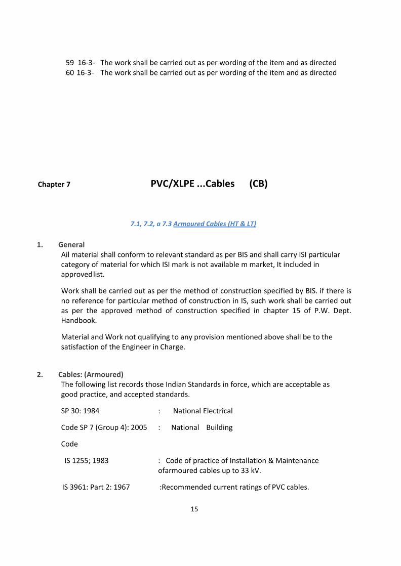
59 16-3- The work shall be carried out as per wording of the item and as directed 60 16-3- The work shall be carried out as per wording of the item and as directed
Chapter 7 PVC/XLPE ...Cables (CB)
7.1, 7.2, a 7.3 Armoured Cables (HT & LT)
1. General Ail material shall conform to relevant standard as per BIS and shall carry ISI particular category of material for which ISI mark is not available m market, It included in approved list.
Work shall be carried out as per the method of construction specified by BIS. if there is no reference for particular method of construction in IS, such work shall be carried out as per the approved method of construction specified in chapter 15 of P.W. Dept. Handbook.
Material and Work not qualifying to any provision mentioned above shall be to the satisfaction of the Engineer in Charge.
2. Cables: (Armoured) The following list records those Indian Standards in force, which are acceptable as good practice, and accepted standards.
SP 30: 1984 : National Electrical
Code SP 7 (Group 4): 2005 : National Building
Code
IS 1255; 1983 : Code of practice of Installation & Maintenance ofarmoured cables up to 33 kV.
IS 3961: Part 2: 1967 :Recommended current ratings of PVC cables.
16
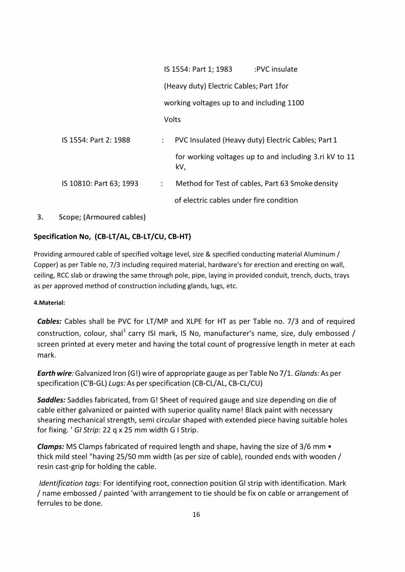
IS 1554: Part 1; 1983 :PVC insulate
(Heavy duty) Electric Cables; Part 1for
working voltages up to and including 1100
Volts
IS 1554: Part 2: 1988 : PVC Insulated (Heavy duty) Electric Cables; Part 1
for working voltages up to and including 3.ri kV to 11 kV,
IS 10810: Part 63; 1993 : Method for Test of cables, Part 63 Smoke density
of electric cables under fire condition
3. Scope; (Armoured cables)
Specification No, (CB-LT/AL, CB-LT/CU, CB-HT)
Providing armoured cable of specified voltage level, size & specified conducting material Aluminum /
Copper) as per Table no, 7/3 including required material, hardware's for erection and erecting on wall,
ceiling, RCC slab or drawing the same through pole, pipe, laying in provided conduit, trench, ducts, trays
as per approved method of construction including glands, lugs, etc.
4.Material:
Cables: Cables shall be PVC for LT/MP and XLPE for HT as per Table no. 7/3 and of required
construction, colour, shal1 carry ISI mark, IS No, manufacturer's name, size, duly embossed /
screen printed at every meter and having the total count of progressive length in meter at each
mark.
Earth wire: Galvanized Iron (G!) wire of appropriate gauge as per Table No 7/1. Glands: As per specification (C'B-GL) Lugs: As per specification (CB-CL/AL, CB-CL/CU)
Saddles: Saddles fabricated, from G! Sheet of required gauge and size depending on die of cable either galvanized or painted with superior quality name! Black paint with necessary shearing mechanical strength, semi circular shaped with extended piece having suitable holes for fixing. ' GI Strip: 22 q x 25 mm width G I Strip.
Clamps: MS Clamps fabricated of required length and shape, having the size of 3/6 mm • thick mild steel "having 25/50 mm width (as per size of cable), rounded ends with wooden / resin cast-grip for holding the cable.
Identification tags: For identifying root, connection position Gl strip with identification. Mark / name embossed / painted 'with arrangement to tie should be fix on cable or arrangement of ferrules to be done.

17
Hardware: Sheet Metal (tfo) screws of required sizes, plugs / wooden gutties, etc.
4. Method of Construction;
Irrespective of method of construction the cable ends shall be terminated with appropriate size & type of glands with lugs duly crimped, as directed by Site engineer.
Wherever the cable has to be bent, the turning radius shall be as mentioned in Table No 7/2. Grouping of cables shall be done with adequate distance between cables as mentioned in IS so as to minimize the jointing. Cables shall be tagged/ferruled with identification name / mark at the point from where distribution starts and at ends. Bar earth wire of appropriate size As per Table- r-o. 7/1 shall run along with the .cable. Earth wire running with the cable shall be terminated at the earth terminal nearest to. Cable termination.
5.1 Erection of Cable on Surface:
Erection shall be done as per the routes and layout finalized, in perfect level and in plumb. Before fixing the cable shall be straightened as far as possible for good aesthetics look, continuous bare Gl earth wire of required gauge as per Table No 7/1 shall be run. Cable with G I wire shall be fixed by saddles firmly clipped on cable and shall be fixed to wall, with minimum 50 x 8 mm SM screws with plugs/wooden gutties, etc. {Distance between two supports / saddles shall be maximum 450 mm). Wooden gutties shall be used wherever required (especially for stone wall}. The entries made in wall, floor slab, etc for laying trie. Cable shall be made good by filling and finishing with plastering the same.
5.2 Erection of Cable on Trusses:
Cable along with bare Gl earth wire, while erecting on trusses, shall be firmly clamped by wrapping GI strip of 22_g, 25 mm width of required length fixed to truss with nuts and bolts.
5.3 Erection of Cable on Pole:
Cable along with bare GI earth wire, while erecting on pole, shall be firmly clipped by suitable wooden / epoxy resin cast grips, clamped with 25 x 3 mm or50x6 mm MS strip of required length and fixed to pole with nuts and bolts.
5.4 Laying of Cable in provided Trench/Pole:
While laying Cable along with bare G! Earth wire, utmost care shall be taken to prevent damage to the insulation of the cable and to the open end. Cable shall be brought out from trench vertically straight (minimum 1, 0 meter above G L). Care shall be taken to inspect the trench so that depth of cable shall not be less than as shown in Table No 7/4. Suitable size of cable loops shall be provided near termination point at adequate depth.
5.5 Erecting cable in constructed Trencft / duct:
Erection of cable/s in constructed trench / duct, shall be as per guide lines of IS 1255.
18
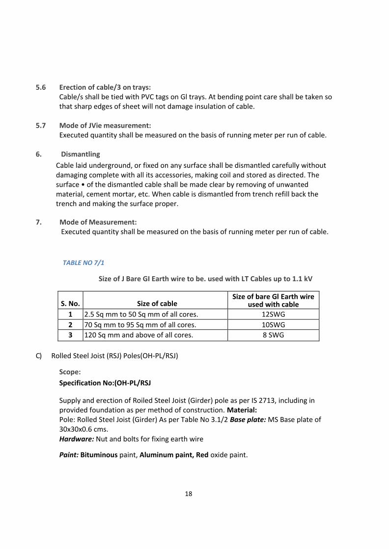
5.6 Erection of cable/3 on trays: Cable/s shall be tied with PVC tags on Gl trays. At bending point care shall be taken so that sharp edges of sheet will not damage insulation of cable.
5.7 Mode of JVie measurement: Executed quantity shall be measured on the basis of running meter per run of cable.
6. Dismantling
Cable laid underground, or fixed on any surface shall be dismantled carefully without damaging complete with all its accessories, making coil and stored as directed. The surface • of the dismantled cable shall be made clear by removing of unwanted material, cement mortar, etc. When cable is dismantled from trench refill back the trench and making the surface proper.
7. Mode of Measurement: Executed quantity shall be measured on the basis of running meter per run of cable.
TABLE NO 7/1
Size of J Bare GI Earth wire to be. used with LT Cables up to 1.1 kV
S. No.
Size of cable Size of bare Gl Earth wire
used with cable
1 2.5 Sq mm to 50 Sq mm of all cores. 12SWG
2 70 Sq mm to 95 Sq mm of all cores. 10SWG
3 120 Sq mm and above of all cores. 8 SWG
C) Rolled Steel Joist (RSJ) Poles(OH-PL/RSJ)
Scope:
Specification No:(OH-PL/RSJ
Supply and erection of Roiled Steel Joist (Girder) pole as per IS 2713, including in provided foundation as per method of construction. Material: Pole: Rolled Steel Joist (Girder) As per Table No 3.1/2 Base plate: MS Base plate of 30x30x0.6 cms. Hardware: Nut and bolts for fixing earth wire
Paint: Bituminous paint, Aluminum paint, Red oxide paint.

19
Method of Construction:
Before erection of pole base plate of size 30x30x0.6 cm shall be full length welded, at the bottom of pole, a suitable hole of required diameter and at specified height shall be drilled for earth stilled. The pole shall be then painted by 2 coats of red oxide paint as primer for full length and then by one coat of bituminous paint before erection for min,1/6 length which is to be buried in ground & after erection remaining portion-to be-painted by two coats of aluminum paint. The pole shall be erected in provided pit with cement concrete foundation and muffing in perfect plumb. {As per drawing)
Mode of Measurement:
Executed quantity will be measured on number basis, (i.e. each)
Table No. 3.1/2
Weight of various sizes of RSJ Poles with 8.5 meter length
RSJ POLE Size Weight per Meter
Rolled steel Joist 1 50x80 /150x75mm
14.9 Kg/meter
Rolled steel Joist 200x1 00 mm 25,4 Ka/meter
Rolled steel Joist 175x90 mm 19.3 Kg/meter
Rolled steer Joist 100x11 6 mm 23.0 Kg/meter
Rolled steel Joist 125x75 mm 12.42 Ka/meter
Rolled steel Joist 152x1 52 mm 37.0 Kg/meter
Rail Poles(OHPL/RLP) Scope;
Specification No (OH-PL/RLP)
Supply and erection of Rail. Pole including painting in provided foundation as per
method of construction. Material
Pole: Rail Pole 29.76 Kg/ meter, as per IS 2713 (Part II)
Base plate: MS Base plate of 30x30x0.6 cms.
Hardware: Nut and bolts for fixing earth wire
Paint: Bituminous paint, Aluminum paint. Red oxide paint.
Before erection of pole, base plate of size 30x30x0,6 cm shall be full length welded or fixed with
20
4 set screws at the bottom of pole, a suitable hole of required diameter and at 'specified height
shall be drilled for earth stud. The pole shall be then painted by 2 coats of Ted oxide paint as
primer for full length and then by one coat of bituminous paint before erection for 1/6 length
which is to be buried in ground & after, erection remaining portion is to be painted by two
coats of aluminum paint The pole shall be erected in provided pit with cement concrete
foundation and muffing in perfect plumb.
Mode of Measurement:
Executed quantity will be measured on number basis, (i.e. each)
5.5 Moulded Case Circuit Breaker (MCCB) (MCCB)
Scope:
Specification No( SW-SWR/MCCB)
Providing & erecting 3 Pole/4 Pole MCCB of specified rating and with specified short circuit rupturing capacity in KA, complete erecting in provided enclosure & connected with provided leads on incoming and outgoing side, complete.
General Specifications for MCCB's
MCCB's should comply with IS 13947 part -2, IEC (6094) and IEC 60947-3 & IEC 60947
part - 2.
The MCCB shall be suitable for universal mounting i.e. the load/line shall be interchangeable with shrouded incoming contacts.
The MCCB shall be suitable for minimum operating voltage of 415V.
The thermal setting shall be adjustable from 64 % to 100% of its normal current.
The magnetic setting shall be adjustable from 3.5 to 10 In (normal current).
Trip reset should be available Manual / Automatic.
Isolator switches for electronic circuits to open the MCCB automatically.
The MCCB's must house transparent label holder to ensure circuit identification.
The MCCB's must have fully insulated safety shutters.
Overload Zone adjustable from 0.4 to 1 in with line (For 630 amp & above MCCB)
Short circuit Zone adjustable from 1.5 to 10 In with time.
Material: 3 pole or 4 Pole MCCB Moulded case circuit breaker. Fixed version- front Terminals with current rating & breaking capacity as below:
i. 63 A to 125 A - 15 KA ii. 160 A to 250 A - 35 KA iii. 300/400 A - 35 KA iv. 630 A - 70 KA
Method of Construction: 3 pole /4 pole MCCB shall be erected in provided enclosure & connected with provided leads/strip on incoming & out going site complete
21
Mode of Measurement: Executed quantity shall be counted on number basis. (i.e. each)
Chapter 7 PVC/XLPE Cables (CB)
7.1, 7.2, & 7.3 Armoured Cables (HT & LT)
General
All material shall conform to relevant standard as per BIS and shall carry ISI mark. If any particular category of material for which ISI mark is not available in market, it shall be as included in approved list.
Work shall be carried out as per the method of construction specified by BIS. If there is no reference for particular method of construction in IS, such work shall be carried out as per the approved method of construction specified in chapter 16 of P.W. Dept. Handbook.
Material and Work not qualifying to any provision mentioned above shall be to the satisfaction of the Engineer in Charge.
Cables: (Armoured)
The following list records those Indian Standards in force, which are acceptable as good practice, and accepted standards. SP 30: 1984 : National Electrical Code SP 7 (Group 4): 2005 : National
Building Code IS 1255: 1983 Code of practice of Installation & Maintenance of armoured
cables up to 33 kV. IS 3961: Part 2: 1967: Recommended current ratings of PVC cables. IS 1554: Part 1;
1988 : PVC Insulated (Heavy duty) Electric Cables; Part 1 for working voltages up to and including 1100 Volts.
IS 1554: Part 2; 1988: PVC Insulated (Heavy duty) Electric Cables; Part 1 for working Voltage up to and including 3.3 kV to 11k V .
IS 10810: Part 63; 1993 : Method for Test of cables, Part 63 Smoke density of electric cables under fire condition.
Scope: (Armoured cables)
Specification No. (CB-LT/AL, CB-LT/CU, CB-HT)
Providing armoured cable of specified voltage level, size & specified conducting material (Aluminum / Copper) as per Table no. 7/3 including required material, hardware's for erection and erecting on wall, ceiling, RCC slab or drawing the same through pole, pipe, laying in

22
provided conduit, trench, ducts, trays as per approved method of construction including glands, lugs, etc.
Material:
Cables:
Cables shall be PVC for LT/MP and XLPE for HT as per Table no. 7/3 and of required construction, colour, shall carry ISI mark, IS No, manufacturer's name, size, duly embossed / screen printed at every meter and having the total count of progressive length in meter at each mark. Earth wire: Galvanized Iron (G I) wire of appropriate gauge as per Table No 7/1. Glands: As per specification (CB-GL)
Lugs: As per specification (CB-CL/AL, CB-CL/CU)
Saddles: Saddles fabricated from GI sheet of required gauge and size depending on dia of cable either galvanized or painted with superior quality enamel black paint with necessary shearing mechanical strength, semi circular shaped with extended piece having suitable holes for fixing. G I Strip: 22 g x 25 mm width G I Strip.
Clamps: MS Clamps fabricated of required length and shape, having the size of 3/6 mm thick mild steel having 25/50 mm width (as per size of cable), rounded ends with wooden / resin cast grip for holding the cable. Identification tags: For identifying root, connection position GI strip with identification mark / name embossed / painted with arrangement to tie should be fix on cable or arrangement of ferrules to be done. Hardware: Sheet Metal (SM) screws of required sizes, plugs / wooden gutties, etc.
7.4 & 7.5 Cable Joints & End Termination Kits
(LT/HT Cables) (JT/LT/HT)
1 .Scope:
Specification No (CB-JT/LT/HT)
Providing straight through cable jointing kit of approved make and jointing cable as per the manufacturer's instructions and duly marking name of jointer and date.
2. Material: Joint kit: Kit manufactured by reputed manufacturer with PVC moulds made in two parts, with epoxy compound, earth continuity lead of appropriate cross section having lugs at both ends, aluminum ferrules of the size of the cable, cross shaped epoxy spacer, MS clips for holding the moulds, adhesive for pasting the moulds.
3. Method of Construction: 3.1 Straight through joint Kit: LT/HT Cables
Before providing joint to the cable, the cable ends of the equivalent length of the joint
23
moulds, shall be prepared by removing the outer PVC insulation along with the steel armouring. The ferrule shall then be inserted over the bare core of the cable, and shall be crimped with hydraulic / mechanical type heavy duty crimping tool. The crimped portion shall be wrapped first with the PVC insulation tape and then with the insulation tape used for wrapping HT conductor. The above method shall be carried out for all the cores strictly following the colour code. The leads of the both the cables now shall be placed into the mould by using the epoxy spacer, for having sufficient gap in-between the leads. The earth continuity lead shall be clamped to the both ends of the cable. After covering the cable leads with the PVC moulds, the edges shall be clipped after applying the adhesive on the inside face of the moulds. The pasting of moulds shall be rigid and as far as possible leak proof, so that the epoxy compound shall not spill out. Now the duly stirred epoxy compound shall be poured and fill till the compound rises through the risers provided on the moulds. After completing the above procedure, the joint shall be allowed to dry out for at least 8 to 10 hours (for epoxy compound to get hardened) depending upon the size of cable. Before connecting to supply, the dry and hardened joint shall be tested for its insulation level with 1000 V/ 5000 V Meggar. The cable should be fixed or laid in such manner that there should not be pressure on end of moulds or on jointing position of cables. (Refer drawing No. CB-JT-1)
3.2 Outdoor/Indoor end termination Kit: L T/HT Cables
Before providing end termination kit to the cable, the cable end of the equivalent length of the moulds, shall be prepared by removing the outer PVC insulation along with the steel armouring. The ferrule shall then be inserted over the bare core of the cable, and shall be crimped with hydraulic / mechanical type heavy duty crimping tool. The crimping shall be done in such a manner that there shall be no air gap. Then the crimped portion shall be wrapped first with the PVC insulation tape and then with the insulation tape used for wrapping HT conductor. The above method shall be carried out for all the cores strictly following the colour code. The leads of the cable now shall be placed into the mould by using the epoxy spacer, for having sufficient gap in-between the leads. The earth continuity lead shall be clamped to the ends of the cable. After covering the cable leads with the PVC moulds, the edges shall be clipped after applying the adhesive on the inside face of the moulds. The pasting of moulds shall be rigid and as far as possible leak proof, so that the epoxy compound shall not spill out. Now the duly stirred epoxy compound shall be poured and fill till the compound rises through the risers provided on the moulds.(Refer drawing No. CB-JT-2) After completing the above procedure, the joint shall be allowed to dry out for at least 8 to 10 hours (for epoxy compound to get hardened) depending upon the size of cable. Before connecting to supply, the dry and hardened joint shall be tested for its insulation level with 1000 V/ 5000 V Meggar
4 Mode of Measurement:
Executed quantity will be measured on number basis. (i.e. each).
24
7.7 Cable Glands (GL) Scope:
Specification Nos. (CB-GL)
Termination of cable ends with cable glands for preparing and fixing the cable leads for connection. Cable glands shall be of Flange type.
Material:
Cable glands: Flange type heavy duty. Made of high purity brass metal, with brass washers, rubber rings, threaded stud with washers and nuts. Method of Construction
Before erection of gland, the cable end shall be prepared by removing the outer PVC insulation up to the point where gland to be fixed, by assessing the length of leads required. Bottom portion of gland shall be inserted over the steel armouring, and then armour strips shall be bent for the length of collar of gland, remaining length of armoring shall be cut. The cable end shall then be, inserted through the entry of plate where the cable is to be terminated. The top portion of gland with washer shall be then inserted in such a manner that the bent armour strip should be touching the surface of the entry. The nuts shall be tightened with spring washers over the projected stud portion. Fixing of gland shall be at right angle to the gland plate. Tightening shall assure continuity of earth. Hole to the gland plate shall be punched / knocked out, of correct diameter with respect to gland size.
Mode of Measurement:
Executed quantity will be measured on number basis. (i.e. each)
7.9 & 7.10 Cable Lugs (Aluminum & Copper)
2. Scope:
Specification Nos. (CB-CL/AL, CB-CL/CU)
Crimping of lugs, and fixing to the terminals with nuts and bolts, etc.
3. Material:
Lug: Lug shall be of high purity aluminum / copper / bimetallic of required type, with required size of hole and smooth finished both from inside and outside. Hardware: Brass or Cadmium plated mild steel nuts and bolts, bimetallic washers. Anti-Oxide paste: Paste of superior quality manufactured by reputed manufacturer.
4. Method of Construction:
25
Before fixing of lugs to the cable end, the cable end to the equivalent length of the lug shall be prepared by removing the outer PVC insulation along with the steel armouring and then, the inner PVC insulation. The paste shall be applied to the cable lead and inside the lug prior to the inserting of lug on the cable lead. The lug shall then be crimped with hydraulic / mechanical type heavy duty crimping tool. The crimping shall be done in such a manner that there shall be no air gap. Then the crimped portion shall be wrapped with the PVC insulation tape. (Colour of tape shall be of that of cable lead) The above method shall be carried out for all the cores. The cable end with lug shall then be terminated into the terminal and then be tightened with either brass nuts or Cadmium plated nuts as directed by Engineer in-charge.
5. Mode of Measurement:
Executed quantity will be measured on number basis. (i.e. each).
Chapter 8 Overhead Systems (OH)
8.1 Steel Poles (OH-PL)
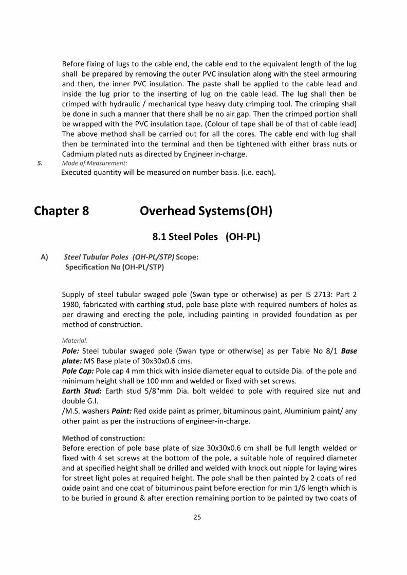
A) Steel Tubular Poles (OH-PL/STP) Scope: Specification No (OH-PL/STP)
Supply of steel tubular swaged pole (Swan type or otherwise) as per IS 2713: Part 2 1980, fabricated with earthing stud, pole base plate with required numbers of holes as per drawing and erecting the pole, including painting in provided foundation as per method of construction.
Material:
Pole: Steel tubular swaged pole (Swan type or otherwise) as per Table No 8/1 Base plate: MS Base plate of 30x30x0.6 cms. Pole Cap: Pole cap 4 mm thick with inside diameter equal to outside Dia. of the pole and minimum height shall be 100 mm and welded or fixed with set screws. Earth Stud: Earth stud 5/8"mm Dia. bolt welded to pole with required size nut and double G.I. /M.S. washers Paint: Red oxide paint as primer, bituminous paint, Aluminium paint/ any other paint as per the instructions of engineer-in-charge.
Method of construction: Before erection of pole base plate of size 30x30x0.6 cm shall be full length welded or fixed with 4 set screws at the bottom of the pole, a suitable hole of required diameter and at specified height shall be drilled and welded with knock out nipple for laying wires for street light poles at required height. The pole shall be then painted by 2 coats of red oxide paint and one coat of bituminous paint before erection for min 1/6 length which is to be buried in ground & after erection remaining portion to be painted by two coats of

26
aluminium paint. The pole shall be erected in provided pit with cement Concrete foundation and muffing in perfect plumb.
Mode of Measurement:
Executed quantity will be measured on number basis. (I.e. each) Supply and erection of Rolled Steel Joist (Girder) pole as per IS 2713, including painting in provided foundation as per method of construction. Material: Pole: Rolled Steel Joist (Girder) As per Table No 8.1/2 Base plate: MS Base plate of
30x30x0.6 cms. Hardware: Nut and bolts for fixing earth wire Paint: Bituminous paint,
Aluminium paint, Red oxide paint. Method of construction:
Before erection of pole base plate of size 30x30x0.6 cm shall be full length welded at the bottom of pole, a suitable hole of required diameter and at specified height shall be drilled for earth stud. The pole shall be then painted by 2 coats of red oxide paint as primer for full length and then by one coat of bituminous paint before erection for min.1/6 length which is to be buried in ground & after erection remaining portion to be painted by two coats of aluminium paint. The pole shall be erected in provided pit with cement concrete foundation and muffing in perfect plumb.
Mode of Measurement:
Executed quantity will be measured on number basis. (i.e. each) Table No. 8.1/2 Weight of various sizes of RSJ Poles with 8.5 meter length RSJ POLE Size
Weight per Meter Rolled steel Joist 150x80 / 150x75mm 14.9 Kg/meter Rolled steel Joist 200x100 mm 25.4 Kg/meter Rolled steel Joist 175x90 mm 19.3 Kg/meter Rolled steel Joist 100x116 mm 23.0 Kg/meter Rolled steel Joist 125x75 mm 12.42 Kg/meter Rolled steel Joist 152x152 mm 37.0 Kg/meter
Rail Poles (OH-PL/RLP) Scope: Specification No (OH-PL/RLP)
Supply and erection of Rail Pole including painting in provided foundation as per method of construction.
Material:
Pole: Rail Pole 29.76 Kg/ meter, as per IS 2713 (Part II) Base plate: MS Base plate of 30x30x0.6 cms.
Hardware: Nut and bolts for fixing earth wire
Paint: Bituminous paint, Aluminium paint, Red oxide paint.
27
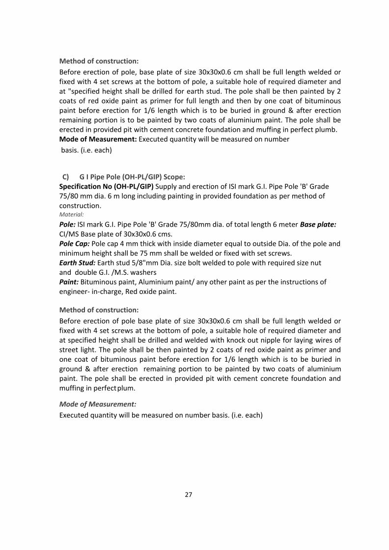
Method of construction:
Before erection of pole, base plate of size 30x30x0.6 cm shall be full length welded or fixed with 4 set screws at the bottom of pole, a suitable hole of required diameter and at "specified height shall be drilled for earth stud. The pole shall be then painted by 2 coats of red oxide paint as primer for full length and then by one coat of bituminous paint before erection for 1/6 length which is to be buried in ground & after erection remaining portion is to be painted by two coats of aluminium paint. The pole shall be erected in provided pit with cement concrete foundation and muffing in perfect plumb. Mode of Measurement: Executed quantity will be measured on number
basis. (i.e. each)
C) G I Pipe Pole (OH-PL/GIP) Scope: Specification No (OH-PL/GIP) Supply and erection of ISI mark G.I. Pipe Pole 'B' Grade 75/80 mm dia. 6 m long including painting in provided foundation as per method of construction. Material:
Pole: ISI mark G.I. Pipe Pole 'B' Grade 75/80mm dia. of total length 6 meter Base plate: CI/MS Base plate of 30x30x0.6 cms. Pole Cap: Pole cap 4 mm thick with inside diameter equal to outside Dia. of the pole and minimum height shall be 75 mm shall be welded or fixed with set screws. Earth Stud: Earth stud 5/8"mm Dia. size bolt welded to pole with required size nut and double G.I. /M.S. washers Paint: Bituminous paint, Aluminium paint/ any other paint as per the instructions of engineer- in-charge, Red oxide paint.
Method of construction:
Before erection of pole base plate of size 30x30x0.6 cm shall be full length welded or fixed with 4 set screws at the bottom of pole, a suitable hole of required diameter and at specified height shall be drilled and welded with knock out nipple for laying wires of street light. The pole shall be then painted by 2 coats of red oxide paint as primer and one coat of bituminous paint before erection for 1/6 length which is to be buried in ground & after erection remaining portion to be painted by two coats of aluminium paint. The pole shall be erected in provided pit with cement concrete foundation and muffing in perfect plum.
Mode of Measurement:
Executed quantity will be measured on number basis. (i.e. each)
28
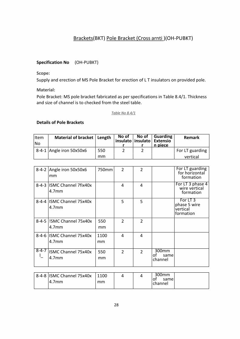
Brackets(BKT) Pole Bracket (Cross arnti )(OH-PUBKT)
Specification No (OH-PUBKT)
Scope:
Supply and erection of MS Pole Bracket for erection of L T insulators on provided pole.
Material:
Pole Bracket: MS pole bracket fabricated as per specifications in Table 8.4/1. Thickness and size of channel is to checked from the steel table.
Table No 8.4/1
Details of Pole Brackets
Item No
Material of bracket Length No of insulato
r
No of insulato
r
Guarding Extensio n piece
Remark
8-4-1 Angle iron 50x50x6 550 mm
2 2 For LT guarding
vertical
8-4-2 Angle iron 50x50x6
mm 750mm 2 2 For LT guarding
for horizontal formation
8-4-3 ISMC Channel 7fix40x 4.7mm
4 4 For LT 3 phase 4 wire vertical
formation
8-4-4 ISMC Channel 75x40x 4.7mm
5 5 For LT 3 phase 5 wire vertical formation
8-4-5 !SMC Channel 75x40x 4.7mm
550 mm
2 2
8-4-6 ISMC Channel 75x40x 4.7mm
1100 mm
4 4
8-4-7 l_
ISMC Channel 75x40x 4.7mm
550 mm
2 2 300mm of same channel
8-4-8 ISMC Channel 75x40x 4.7mm
1100 mm
4 4 300mm of same channel

29
D' type Clamps: MS Flat of 50x6mrn, 15 mm MS nut bolts Paint: Silver paint, Red oxide paint
Method of construction:
The cross arm shall be made up of size of channel mentioned in above table. The length shall be as stated above table. The cross arm shall be complete with pole clamp of size 50X6 mm MS flat and holes required for pin / shackle insulator. For MS pole bracket with guarding extension, a extension piece of same size of length 300 mm shall be welded to bracket as per drawing attached herewith. The cross arm and pole clamp shall be painted with one coat of red oxide and two coat/silver enamel paint any other colour paint (as per the instructions of engineer in-charge). Cross arm shall be fabricated as per drawing no.
Mode of Measurement: Executed quantity will be measured on number basis, (i.e. Each)
B) Aluminium Conductor. Steel Reinforced (ACSR) (OH-CGN/ACSR) Scope: Specification No (OH-CGN/ACSR) Supply and erection of aluminium conductor steel reinforced for overhead line. Material: Conductor: All aluminium conductor steel reinforced (As per table 8.5/1) Binding wire: 12 SWG aluminium binding wire C/amps: PG clamps as per requirement
Method of construction:
At. first the conductor "is removed from bundle/drum straighten without knots, -bends, etc. Stringing of conductor shall be done with draw vice. Conductor shall not be twisted while stringing. Disc insulators shall be used if. the line deviates by 30 degrees or more, terminal pole and tri-pole or four pole structure at terminal pole and at junction/ cut pole. Parallel double groove clamp having two nut bolts designated to carry full line current shall be used for making Jumper wire connections. Universal .parallel double groove clamp having two nut bolts shall be used for Tap Off point. On straight line the conductor shall be bounded on top groove of insulator and at angular
position, binding shall be done in side groove. Binding wire of 12 SWG shall be of the same metal as that o ' conductor.
Mode of Measurement
For measurement purpose, sum of the total conductor including jumper connections shall be considered,(i.e. per km)'
Table No 8.5/1 Conductor Specifications As Per I.'S.
398/1961

30
Table No 8.5/2 Minimum Clearances between Conductors (13:4237-1967)
Code Name of Conductor
Resistance at 20° ohm /km.
Approx, Current Carrying Capacity in Amperes.
Number of Strands / Diameter of each
Overall ] Diameter of Conducto r in
Weight of I Conducto r i (kg/km)
At 40°C At 45° C
AH Aluminium Conductor Rose 1,361 116 108 7/1 .96 5.88 58
Gnat 1.071 133 123 7/2.21 6.63 73
Irish 0.850 150 138 7/2.48 7.44 92
Pansy 0.677 178 165 7/2.78 8.34 116
Ant 0.544, - . 204 189 7/3.10 ' 9.30 . 144
ACSR Conductor Squirrel 1 .374 115 107 6+ 1/2.11 6.33 85
Weasel 0.911 150 139 6+ 1/2.59 7.77 128
Ferret 4.G4 o.6?g 181 618 6+ 1/3.0 9.00 171
Mink 0.06 0.456 234 217 6+ 3.66 10.98 255
Raccoon 0.365 270 250 6+ 1/4.09 12.27 318
Dog 0.1 1.137 520 482 30+ 7/3.0 21.00 976
S. No. Voltage level (kV)
Clearance in mm
Between Phases
Between Phase & Earth
7. 11 460 305
8. 22 610 460
9. 33 915 610
10. 110 1675 1000
11. 230 3350 1675
12. 400 4000 3500

31
8.5 Conductors(CON) All Aluminium Conductors (AAC) (OH-CON/AAC)
Scope:
Specification No (OH-CON/AAC)
Supply and erection of All Aluminium Conductors for overhead line. Material: Conductor: All aluminium stranded conductor (As per table 8.5/1) Binding wire: 12 SWG aluminium
binding wire
Clamps: PG clamps as per requirement
Method of construction:
At first the conductor is removed from bundle/drum straighten without knots, bends, etc. Stringing of conductor shall be done with draw vice. Conductor shall not be twisted while stringing. Shackle insulators shall be used if the line deviates by 30 degrees or more, at terminal pole and at junction/ cut pole. Parallel double groove clamp having two nut bolts designated to carry full line current shall be used for making Jumper wire connections. On straight line the conductor shall be bounded on top groove of insulator and at angular position binding shall be done in side groove. Binding wire of 12 SWG shall be of the same metal as that of conductor.
Mode of Measurement:
For measurement purpose, sum of the total conductor including jumper connections shall be considered. (i.e. per km)
B)Aluminium Conductor Steel Reinforced (ACSR) (OH-CON/ACSR) Scope:
Specification No(OH-CON/ACSR)
Supply and erection of aluminium conductor steel reinforced for overhead line. Material: Conductor: All aluminium conductor steel reinforced (As per table 8.5/1) Binding wire: 12 SWG aluminium binding wire Clamps: PG clamps as per requirement
Method of construction:
At first the conductor is removed from bundle/drum straighten without knots, bends, etc. Stringing of conductor shall be done with drawing vice. Conductor shall not be twisted while stringing. Disc insulators shall be used if the line deviates by 30 degrees or more, terminal pole and tri-pole or four pole structure at terminal pole and at junction/ cut pole. Parallel double groove clamp having two nut bolts designated to carry full line current shall be used for making Jumper wire connections. Universal parallel double groove clamp having two nut bolts shall be used for Tap Off point. On straight line the conductor shall be bounded on top groove of
32
insulator and at angular position binding shall be done in side groove. Binding wire of 12 SWG shall be of the same metal as that of conductor.
Mode of Measurement:
For measurement purpose, sum of the total conductor including jumper connections shall be considered. (i.e. per km)
8.6 Insulators (INS)
A) Porcelain Disc Type Insulator 11/22/33 kV (OH-INS/DI) Scope:
Specification No (OH-INS/DI)
Supplying porcelain disc type insulator, suitable for 11/22/33KV and necessary ancillary materials and complete erection on provided cross arm / bracket and connected to the overhead line as per instructions from the site engineer
Material:
Insulator: Distribution class Disc type insulator made from porcelain, suitable for specified voltage level, having ISI mark, with necessary hardware. Hardware: Nuts, washers, etc.
Binding wire: Bare Copper wire or conductor.
Clamps: MS clamps.
Method of construction:
Distribution class porcelain disc type insulator, suitable for specified voltage level, erected on provided cross arm or bracket with clamps, ancillary materials, and connected to the over-head line. Connection shall be made with bare copper wire of specified gauge. Mode of Measurement: Executed quantity will be measured on number basis (i.e. each)
B)Pin Type Insulator 11/22/33 kV (OHINS/PN) Scope:
Specification No (OH-INS/PN)
Supplying porcelain Pin type insulator, suitable for 11/22/33KV and necessary ancillary materials and complete erection on provided cross arm / bracket and connected to the overhead line as per instructions from the site engineer
Material:
Insulator: Distribution class Pin type insulator made from porcelain, suitable for specified voltage level, having ISI mark, with necessary hardware. Hardware: Nuts, washers, etc.
Binding wire: Bare Copper wire or conductor.
Clamps: MS clamps.
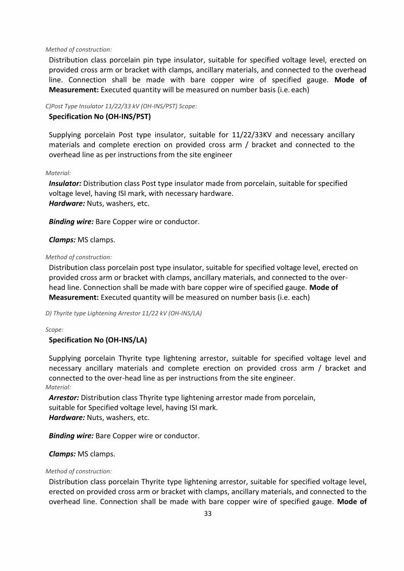
33
Method of construction:
Distribution class porcelain pin type insulator, suitable for specified voltage level, erected on provided cross arm or bracket with clamps, ancillary materials, and connected to the overhead line. Connection shall be made with bare copper wire of specified gauge. Mode of Measurement: Executed quantity will be measured on number basis (i.e. each)
C)Post Type Insulator 11/22/33 kV (OH-INS/PST) Scope:
Specification No (OH-INS/PST)
Supplying porcelain Post type insulator, suitable for 11/22/33KV and necessary ancillary materials and complete erection on provided cross arm / bracket and connected to the overhead line as per instructions from the site engineer
Material:
Insulator: Distribution class Post type insulator made from porcelain, suitable for specified voltage level, having ISI mark, with necessary hardware. Hardware: Nuts, washers, etc.
Binding wire: Bare Copper wire or conductor.
Clamps: MS clamps.
Method of construction:
Distribution class porcelain post type insulator, suitable for specified voltage level, erected on provided cross arm or bracket with clamps, ancillary materials, and connected to the over-head line. Connection shall be made with bare copper wire of specified gauge. Mode of Measurement: Executed quantity will be measured on number basis (i.e. each)
D) Thyrite type Lightening Arrestor 11/22 kV (OH-INS/LA)
Scope:
Specification No (OH-INS/LA)
Supplying porcelain Thyrite type lightening arrestor, suitable for specified voltage level and necessary ancillary materials and complete erection on provided cross arm / bracket and connected to the over-head line as per instructions from the site engineer.
Material:
Arrestor: Distribution class Thyrite type lightening arrestor made from porcelain, suitable for Specified voltage level, having ISI mark. Hardware: Nuts, washers, etc.
Binding wire: Bare Copper wire or conductor.
Clamps: MS clamps.
Method of construction:
Distribution class porcelain Thyrite type lightening arrestor, suitable for specified voltage level, erected on provided cross arm or bracket with clamps, ancillary materials, and connected to the overhead line. Connection shall be made with bare copper wire of specified gauge. Mode of
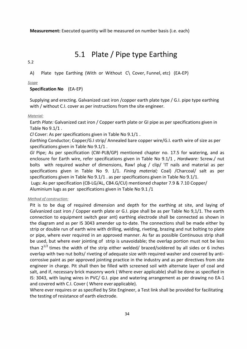
34
Measurement: Executed quantity will be measured on number basis (i.e. each)
5.1 Plate / Pipe type Earthing 5.2
A) Plate type Earthing (With or Without C\ Cover, Funnel, etc) (EA-EP)
Scope
Specification No (EA-EP)
Supplying and erecting. Galvanized cast iron /copper earth plate type / G.I. pipe type earthing with / without C.I. cover as per instructions from the site engineer.
Material:
Earth Plate: Galvanized cast iron / Copper earth plate or GI pipe as per specifications given in Table No 9.1/1 . Cl Cover: As per specifications given in Table No 9.1/1 . Earthing Conductor; Copper/G.I strip/ Annealed bare copper wire/G.I. earth wire of size as per specifications given in Table No 9.1/1 . GI Pipe; As per specification (CW-PLB/GP) mentioned chapter no. 17.5 for watering, and as enclosure for Earth wire, refer specifications given in Table No 9.1/1 , Hardware: Screw./ nut bolts with required washer of dimensions, Raw! plug / clip/ 'IT nails and material as per specifications given in Table No 9. 1/1. Fining material; Coal) /Charcoal/ salt as per specifications given in Table No 9.1/1 . as per specifications given in Table No 9.1/1. Lugs: As per specification (CB-LG/AL, CB4.G/CU) mentioned chapter 7.9 & 7.10 Copper/
Aluminium lugs as per specifications given in Table No 9.1 /1
Method of construction:
Pit is to be dug of required dimension and depth for the earthing at site, and laying of Galvanized cast iron / Copper earth plate or G.I. pipe shall be as per Table No 9,1/1. The earth connection to equipment switch gear ant) earthing electrode shall be connected as shown in the diagram and as per IS 3043 amender up to-date. The connections shall be made either by strip or double run of earth wire with drilling, welding, riveting, brazing and nut bolting to plate or pipe, where ever required in an approved manner. As far as possible Continuous strip shall be used, but where ever jointing of strip is unavoidable; the overlap portion must not be less
than 21/2 times the width of the strip either welded/ brazed/soldered by all sides or 6 inches overlap with two nut bolts/ riveting of adequate size with required washer and covered by anti-corrosive paint as per approved jointing practice in the industry and as per directives from site engineer in charge. Pit shall then be filled with screened soil with alternate layer of coal and salt, and if, necessary brick masonry work ( Where ever applicable) shall be done as specified in IS: 3043, with laying wires in PVC/ G.I. pipe and watering arrangement as per drawing no EA-1 and covered with C.I. Cover ( Where ever applicable). Where ever requires or as specified by Site Engineer, a Test link shall be provided for facilitating the testing of resistance of earth electrode.
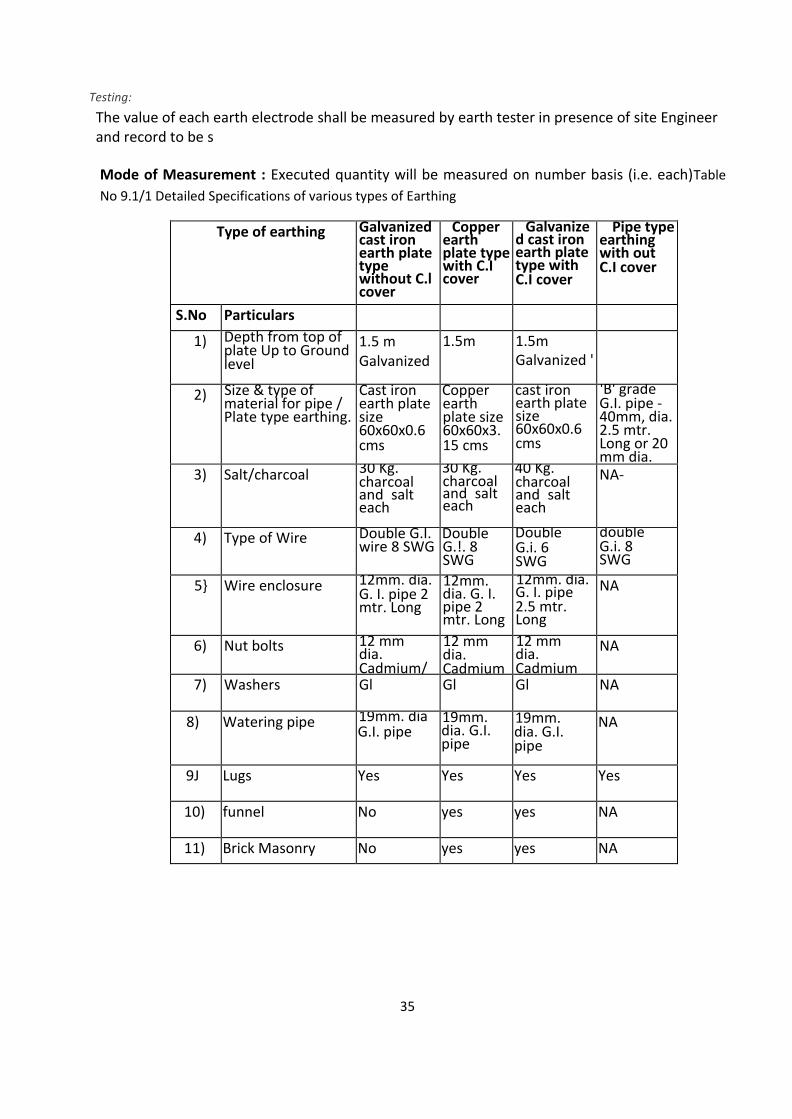
35
Testing:
The value of each earth electrode shall be measured by earth tester in presence of site Engineer and record to be s
Mode of Measurement : Executed quantity will be measured on number basis (i.e. each)Table
No 9.1/1 Detailed Specifications of various types of Earthing
Type of earthing Galvanized cast iron earth plate type without C.l cover
Copper earth plate type with C.I cover
Galvanize d cast iron earth plate type with C.I cover
Pipe type earthing with out C.I cover
S.No Particulars
1) Depth from top of plate Up to Ground level
1.5 m Galvanized
1.5m 1.5m Galvanized '
2) Size & type of material for pipe / Plate type earthing.
Cast iron earth plate size 60x60x0.6 cms
Copper earth plate size 60x60x3. 15 cms
cast iron earth plate size 60x60x0.6 cms
'B' grade G.I. pipe - 40mm, dia. 2.5 mtr. Long or 20 mm dia.
3) Salt/charcoal 30 Kg. charcoal and salt each
30 Kg. charcoal and salt each
40 Kg. charcoal and salt each
NA-
4) Type of Wire Double G.I. wire 8 SWG
Double G.!. 8 SWG
Double G.i. 6 SWG
double G.i. 8 SWG
5} Wire enclosure 12mm. dia. G. I. pipe 2 mtr. Long
12mm. dia. G. I. pipe 2 mtr. Long
12mm. dia. G. I. pipe 2.5 mtr. Long
NA
6) Nut bolts 12 mm dia. Cadmium/
12 mm dia. Cadmium
12 mm dia. Cadmium
NA
7) Washers Gl Gl Gl NA
8) Watering pipe 19mm. dia G.I. pipe
19mm. dia. G.I. pipe
19mm. dia. G.I. pipe
NA
9J Lugs Yes Yes Yes Yes
10) funnel No yes yes NA
11) Brick Masonry No yes yes NA

36
Cable Trench (CTR)
1. General This part of specification deals with the preparation of trenches in soft soil, hard murum, BT road, and laying of cables inside the trench, etc as per IS: 1255,
2. Scope:
Specification No (CW-EXN/CTR)
Excavating in all types of soil strata and making trench for laying cable/cables, providing sand bed for laying the cable, covering cable with specified material as per requirement, and finishing the same by making the surface proper with crown on top of the trench. • The following list shows Indian Standards, which are acceptable as good practice, and accepted standards. SP 30: 1984 : National Electrical Code SP 7 (Group 4); 2005 : National Building Code IS 1255: 1967 : Code of practice of Installation & Maintenance
of armoured cables up to 33 kV. 3. Material:
Bricks: Solid Clay bricks of minimum size 225x110x62.5 mm (L x B x H), burnt in the kiln, of good quality. Sand: Screened sand of good quality.
4. Method of Construction:
Trench in Soft soil / Hard Murum / Tar road" Single run of cable Before excavating the soil for preparing trench, route of cable laying shall be got finalized from the site in-charge. Trench of minimum 300 mm width shall be excavated up to . minimum depth below the ground surface as per Table No 17.1/1 Bottom of the trench should be carefully leveled and freed from stones. Cable duly straightened shall be laid flat and embedded in the 200 mm layer of screened sand at the bottom of the trench. Bricks shall be laid all over the run of cable as specified below: Lengthwise for cable up to and including 10 Sq mm of all cores. Width wise for cable above 10 Sq mm of all cores. Remaining portion of the trench shall be back filled with the excavated material after removing stones and sharp / hard material, and making the surface proper. Crown of 150 mm shall be provided over the trench. The remaining excavated materiaf shall be removed from site and dumped in scrap yard of Local authorities or at suitable place.
Trench in Soft soil / Hard Murum / Tar road: Two or more cables run of cable Before excavating the: 5oii for preparing trench, route of cable laying shall be got finalized from the site in-charge. Trench of minimum required width more than 300mm. shall be excavated up to minimum depth as per Table No
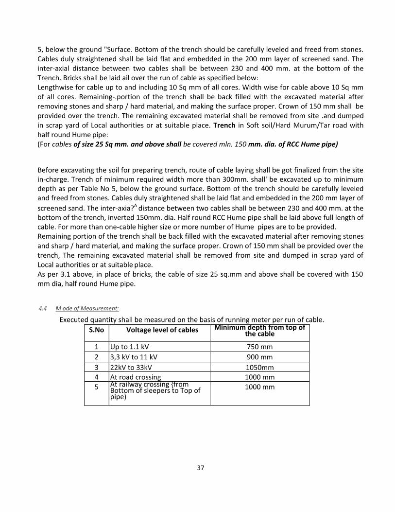
37
5, below the ground "Surface. Bottom of the trench should be carefully leveled and freed from stones. Cables duly straightened shall be laid flat and embedded in the 200 mm layer of screened sand. The inter-axial distance between two cables shall be between 230 and 400 mm. at the bottom of the Trench. Bricks shall be laid ail over the run of cable as specified below: Lengthwise for cable up to and including 10 Sq mm of all cores. Width wise for cable above 10 Sq mm of all cores. Remaining-.portion of the trench shall be back filled with the excavated material after removing stones and sharp / hard material, and making the surface proper. Crown of 150 mm shall be provided over the trench. The remaining excavated material shall be removed from site .and dumped in scrap yard of Local authorities or at suitable place. Trench in Soft soil/Hard Murum/Tar road with half round Hume pipe: (For cables of size 25 Sq mm. and above shall be covered mln. 150 mm. dia. of RCC Hume pipe)
Before excavating the soil for preparing trench, route of cable laying shall be got finalized from the site in-charge. Trench of minimum required width more than 300mm. shall' be excavated up to minimum depth as per Table No 5, below the ground surface. Bottom of the trench should be carefully leveled and freed from stones. Cables duly straightened shall be laid flat and embedded in the 200 mm layer of
screened sand. The inter-axia?A distance between two cables shall be between 230 and 400 mm. at the bottom of the trench, inverted 150mm. dia. Half round RCC Hume pipe shall be laid above full length of cable. For more than one-cable higher size or more number of Hume pipes are to be provided. Remaining portion of the trench shall be back filled with the excavated material after removing stones and sharp / hard material, and making the surface proper. Crown of 150 mm shall be provided over the trench, The remaining excavated material shall be removed from site and dumped in scrap yard of Local authorities or at suitable place. As per 3.1 above, in place of bricks, the cable of size 25 sq.mm and above shall be covered with 150 mm dia, half round Hume pipe.
4.4 M ode of Measurement:
Executed quantity shall be measured on the basis of running meter per run of cable.
S.No Voltage level of cables Minimum depth from top of the cable
1 Up to 1.1 kV 750 mm
2 3,3 kV to 11 kV 900 mm
3 22kV to 33kV 1050mm 4 At road crossing 1000 mm
5 At railway crossing {from Bottom of sleepers to Top of pipe)
1000 mm
38
5.8 LT – Air Circuit Breakers (ACB)
Scope: Specification No (SW-SWR/ACB) Supplying, erecting, and commissioning of Air Circuit
breaker of specified rating, confirming to IS 2516/IES157 manually operated non draw out
type/draw out type erected at position in provided panel board in approved manner.
Material: Air Circuit Breaker: Draw out type/non draw out type manually quick make quick
break type front operated mechanical indication for ON/OFF position with 50 kA short circuit
rating. Trip free mechanism with high performance characteristic based on modular
construction and should be compact. The breaker shall have following accessories:
• Auxiliary Switch: Auxiliary switch shall consist of 2 NO & 2 NC contacts. The total
Auxiliary switch block shall have minimum six auxiliary. In case of draw out breakers two
sliding contacts should be provided. Alarm Switch: For breaker with thermal and magnetic trip
units the indication should be direct from trip unit through micro switch with necessary wiring.
• Shunt Release: Shunt trips are used for remote control. Shunt trip coil should operate
though an auxiliary switch. The operating ranges should be normally 50-110 % of the rated
voltage.
• Under voltage Release: Under voltage release must be energized before closing breaker.
This should be provided for remote control. Over current release: Over current release shall
consist of Current Transformer with slides on each current carrying path of a bi-metal relay
common to all transformers. The transformer shall have a fix ratio suited to particular setting
range. Overload releases shall be thermal time lagged. Overload relay range shall be 50 % to
100 % of CT ratio. Frame shall facilitate site adjustment from 25-100% of ACB rating to match
the load requirement.
• RA unit - given for 0-110% operating range of SHT-ensures supply available to shunt trip
from same AC source in short circuit condition.
• RC unit – for up to 3secs. Timedelay wit U/V trip. Ideal for protection against transient
voltage dips and nuisance tripping continuously adjustable time delay range of 40-500 ms with
S/c trip ideal for selective interruption co- ordination of ACB’s.
• Contacts made of electrolytic copper of 99.9 % purity, of ACB shall be totally shrouded, for
eliminating access to live parts.
• Short Circuit release pick up shall be adjustable for closer protection.
• Breaker shall be compact in size, for saving space in the cubicle and as far as possible shall
be lightweight for easy handling.
• Thermal over load and magnetic short circuit protection shall be provided.
Method of Construction: The breaker should be erected on provided panel board or cubicle as
the case may be, complete with connecting to bus bar by means of provided insulated copper
strip of suitable cross section as per the rating, complete.

39
Mode of Measurement: Executed quantity shall be counted on number basis. (i.e. each)
5.9 HT -- SFU’s, Load Break Switch (HTS)
A. HT Switch Fuse Unit/ Load Break Switch (LBS) Scope: Specification No (SW-HTS/LBS) Supplying and erecting extendable/ non extendable type load break switch with fuses of required rating
and with IP 55 protection class, on provided MS channels/ trench/ foundation in an approved manner.
Recommended Standards:
IS 9920 (Latest Revision):- Rating, performance, testing of load break switch
IS 9921 :- Standards for temperature of electrical parts exposed to air
Load Break Switch should normally comply with the following parameters:
S. No Specifications 11 KV 22 KV
1 Rated Voltage 12 KV 24 KV
2 Rated Current 630A 630 A
3 Rated short time current 25 KA 25 KA 4 Rated making current 62.5 KA 62.5 KA 5 Rated breaking current 630A 630 A 6 Impulse withstand voltage Earth and the 85 KV 145 KV
between poles 75 KV 125 KV Across isolation distance 7 Power frequency test voltage Earth and 32 KV 60KV
between poles 28 KV 50KV Across the isolation distance
Material:
• Steel Sheet • Electrolytic Aluminium Bus bar of 400A • Arc Chutes • Epoxy Resin Cast Type Insulators
• H.T. Fuses of adequate capacity • Shunt Trip Coil • Manual trip push button • Auxiliary contacts • Earth switch • Earth Bus bar copper (25x3)
Method of Construction: Load break switch should be erected on provided MS channels/ trench/
foundation as per approved drawing by site in charge. Manufacturer’s certificate for type test should
40
be obtained. Routine Type test should be carried out at site. An earth switch having separate operating handle should be interlocked with main switch should be checked. An operating handle with correct sequence device having ON and OFF position and arrangement for pad locking provided should be checked. Application: Load break switch is suitable mainly for underground H.T. distribution system. It can be used for switching of transformers, overhead lines, capacitors, ring mains and cables.
Mode of Measurement: Executed quantity will be counted on number basis. (i.e. each)
B. Ring Main Unit: (RMU) Scope:
Specification No (SW-HTS/RMU)
Supplying and erecting Indoor type ring main unit with 2 incoming and 1 outgoing with HRC fuses and with IP 55 protection class, complete erected on provided CC foundation/ MS channels/ trench in an approved manner. (Refer drawing no. SW-HTS-1) Recommended Standards: IS 9920 (Latest Revision):- Rating, performance, testing of Ring Main Unit IS 9921 :- Standards for temperature of electrical parts exposed to air
Material: • Steel Sheet • Electrolytic copper Bus bar of 400 A • Arc Chutes • Epoxy Resin Cast Type Insulators • H.T. Fuses of adequate capacity • Shunt Trip Coil • Manual trip push button • Auxiliary contacts • Earth switch • Earth Bus bar copper (25x3) Method of Construction: Ring main unit should be erected on provided MS channels/ trench/foundation as per approved drawing by site in charge. Manufacturer’s certificate for type test should be obtained. Routine Type test should be carried out at site. An earth switch having separate operating handle should be interlocked with main switch should be checked. An operating handle with correct sequence device having ON and OFF position and arrangement for pad locking provided should be checked.
Application: Ring Main Unit is suitable mainly for underground distribution system. It can be used for switching of transformers, overhead lines, capacitors, ring mains and cables Mode of Measurement: - Per RMU
Mode of Measurement: Executed quantity will be counted on number basis. (i.e. each)
4. Dismantling
Cable laid underground, or fixed on any surface shall be dismantled carefully without damaging
complete with all its accessories, making coil and stored as directed. The surface of the dismantled
cable shall be made clear by removing of unwanted material, cement mortar, etc. When cable is
dismantled from trench refill back the trench and making the surface proper.
Mode of Measurement: Executed quantity shall be measured on the basis of running metre per run 9-1-5 B) Low Impedance Earthing (Pipe in pipe technology)D(EA-EPP)
41
Scope;
Specification No D(EA-EPP)
Supplying -and erecting approved type earthing system with Pipe in pipe technology with necessary ancillary materials and complete erection as per instructions from the site engineer.
Material: GI Pipe: As per specification no. (CW-PLB/GP) mentioned chapter 17.5; 1. 50 mm dia. x 3 meter long (In place of traditional GI pipe Earthing), for LV /MV applications. 2. n 80 mm x 3 meter Song (In place of traditional copper plate Earthing), for HV/EHV applications. Earthing Conductor: G.I strip/GI earth wire of size as per specifications given in the Table No 9.1/1. GI Pipe: As per specification no. (CW-PLB/GP) mentioned chapter 17.5 for watering and as enclosure for Earth wire, as per specifications given in Table No 9.11\. Hardware: Screw/ nut bolts with required washer of dimensions, Rawl plug/clip/ 'U* Nails and material as per specifications given in Table No 9. I I I . Filling material: Coal /Charcoal/ salt as per specifications given in Table No 9.1/1. as per specifications given in Table No 9,1/1. Lugs: As per specification no. (CB-LG/AL, CB-LG/CU) mentioned in chapter 7.9 & 7.10 for Copper/ Aluminium lugs and as per specifications given in Table No 9.1/1.
Method of construction:
Earthing Pipe in pipe technology with ancillary materials shall be done by digging an 8" / 10" dia. hand bore 10.5' deep sufficient to install the electrode in normal soil conditions. The space between the soil and the electrode is filled up with electrolyte material mixed with the dugout mother soil, along with water and tightly packed up to the base of the terminal. In rocky areas and under hard soil and sandy soil conditions the method of installation will be as specified by manufacturer. Installation shall include drilling, welding, reverting, brazing and nut bolting pipe when ever required in an approved manner with required material such as nut bolts and washer etc. and with necessary brick masonry work as per the specification. (As per IS 3043 amended up to-date). As far as possible continuous GI strip shall be used but when ever jointing of strip is un avoidable, the jointing over lap portion must not be less than 21/2 times the width of the strip either welded/ brazed/soldered by all sides or overlap of 6 inch with two nut bolts/ riveting of adequate size with required washer and covered by anti corrosive paint as per approved jointing practice in the industry and as per directives from site engineer in-charge.
Testing:
The value of each earth electrode shall be measured by earth tester and record to be Q submitted. (Also refer drawing No.2)
Mode of Measurement: Executed quantity will be measured on number basis i.e. Each
9.1 Plate / Pipe type Earthing

42
A) Plate type Earthing (With or Without C\ Cover, Funnel, etc) (EA-EP)
Scope
Specification No (EA-EP)
Supplying and erecting. Galvanized cast iron /copper earth plate type / G.I. pipe type earthing with / without C.I. cover as per instructions from the site engineer.
Material:
Earth Plate: Galvanized cast iron / Copper earth plate or GI pipe as per specifications given in Table No 9.1/1. Cl Cover: As per specifications given in Table No 9.1/1 . Earthing Conductor; Copper/G.I strip/ Annealed bare copper wire/G.I. earth wire of size as per specifications given in Table No 9.1/1. GI Pipe; As per specification (CW-PLB/GP) mentioned chapter no. 17.5 for watering, and as enclosure for Earthwire, refer specifications given in Table No 9.1/1 , Hardware: Screw./ nut bolts with required washer of dimensions, Raw! plug / clip/ 'IT nails and material as per specifications given in Table No 9. 1/1. Fining material; Coal) /Charcoal/ salt as per specifications given in Table No 9.1/1 . as per specifications given in Table No 9.1/1. Lugs: As per specification (CB-LG/AL, CB4.G/CU) mentioned chapter 7.9 & 7.10 Copper/ Aluminium lugs as per specifications given in Table No 9.1 /1 .
Method of construction:
Pit is to be dug of required dimension and depth for the earthing at site, and laying of Galvanized cast iron/ Copper earth plate or G.I. pipe shall be as per Table No 9,1/1. The earth connection to equipment switch gerent ) earthing electrode shall be connected as shown in the diagram and as per IS 3043 amender up to-date. The connections shall be made either by strip or double run of earth wire with drilling, welding, riveting, brazing and nut bolting to plate or pipe, where ever required in an approved manner. As far as possible Continuous strip shall be used, but where ever jointing of strip is unavoidable; the overlap portion must not be less than 2times the width of the strip either welded/ brazed/soldered by all sides or 6 inches overlap with two nut bolts/ riveting of adequate size with required washer and covered by anti-corrosive paint as per approved jointing practice in the industry and as per directives from site engineer in charge. Pit shall then be filled with screened soil with alternate layer of coal and salt, and if, necessary brick masonry work ( Where ever applicable) shall be done as specified in IS: 3043, with laying wires in PVC/ G.I. pipe and watering arrangement as per drawing no EA-1 and covered with C.I. Cover ( Where ever applicable). Where ever requires or as specified by Site Engineer, a Test link shall be provided for facilitating the testing of resistance of earth electrode.
43
Testing:
The value of each earth electrode shall be measured by earth tester in presence of site Engineer and record to be s Mode of Measurement: Executed quantity will be measured on number basis (i.e. each)
10.1 Transformer (TR)
Scope: Specification No (SS-TR)
Supplying and erecting AC three phase 11or 22 kV/0.44 kV, 50 Hz, oil immersed and naturally cooled indoor/outdoor type copper wound distribution transformer of specified capacity, connected delta on HV side and star on LV side with additional neutral brought out on load side.
Recommended standards:
The following list shows Indian Standards which are acceptable as good practice and accepted standards. IS 335: 1963 Dielectric Strength IS 2026 part I 1977 Specification for Transformer IS 2026 part II 1977 Specification for type of cooling and permissible temp. Rise of transformer IS 2026 part III 1981 Specification for insulation level and dielectric strength of transformer IS 2026 part IV 1977 Specification for terminal marking tapping and connections. IS 1180 part I 1989 Specification for outdoor type three phase distribution transformer IS 10028 Part I 1985 Code of practice for selection installation and maintenance of transformers CBIP/TAC Manuals
Material:
1. Copper wound Transformer with Delta connection on HV side and star connection on LV side complete with Manufacturer’s test certificates 2. Standard mountings required for transformer are shown below. The mountings are to be selected from them and any additional if required.
Off load tap changing
Oil conservator with fitting holes and cap and plain oil level gauge
Silica gel dehydrating breather
Oil drain valve
Thermometer pockets
Oil filter valve
Lifting arrangement
Two earthing terminals
Diagram and rating plate
Four bi directional plain rollers
Air vent
Explosion vent
Terminal arrangement
Bushing with lugs and/or cable end box on LV side
HV cable end box and/or HV bushing
44
The transformer losses shall be as mentioned in Table No 10.1/1
Method of Construction:
The contractor should intimate name of manufacturer and make of the Transformer and location of the manufacturer factory to engineer in charge prior to delivery of the transformer. After manufacturing of the transformer, the agency/contractor shall intimate the engineer-in-charge for carrying out the inspection. After receipt of intimation engineer-in-charge or his representative should inspect the Transformer at manufacturer factory and shall carry out the following tests jointly in presence of concern contractor. 1. Open Circuit test 2. Short Circuit test 3. Specific Resistance Test 4. Insulation Resistance of HV, LV, in between HV and LV, Winding and Body. 5. Dielectric Strength and acidity test of Transformer oil. The test results of joint inspection shall be recorded on the test report of Transformer with its Sr. No. prior to delivery of the Transformer to site. Necessary work of plinth and or for D.P. structure with D.O. set, L.A., A.B. switch should be completed before dispatch of the transformer. The channel arrangement on plinth is to be done. Earthing arrangement should be completed. The Transformer should be installed on plinths / double pole structure/floor by arranging chains pulley block, crane etc as per IS Norms. After installation of Transformer the stopper/lock should be provided to rollers of the Transformer. The connection of H.T/L.T. side should be completed by provided Copper wire/ cable with necessary lugs to avoid loose connection. The earthing (2 Nos for Neutral & 2 Nos for Body) should be connected from distinct electrodes. The earthing should be connected by lugs/proper size of strip. The Engineer in charge or his representative should check all connections on H.T. side, L.T. side and earths and insulation and earth résistance test should be carried out and results obtained shall be recorded. Statutory Permissions to be obtained by the Agency /Contractor. Before commencement of work, the drawings of installation shall be got approved from the Electrical Inspector, I E & L Department. The installation should be got inspected from Electrical Inspector and obtain written permission to charge the Transformers. Commissioning: After above formalities the Transformer, should be charged/commissioned in presence of Engineer in charge or his representative along with load trials and shall be handed over to the department for beneficial use After charging the Transformer, line, phase voltages and line current shall be measured, and the same shall be submitted. Following test certificates shall be submitted:
1. Manufacturers original certificate of Transformer as stipulated in IS. 2. Test certificate for dielectric strength of oil as per IS. 3. Test results of IR values. 4. Test results of all earth electrodes.
Readings of Voltages & currents at the time of commissioning.
10.2 Accessories (AS)
Scope: Specification No (SS-AS/FSG)
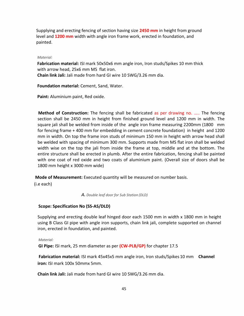
45
Supplying and erecting fencing of section having size 2450 mm in height from ground level and 1200 mm width with angle iron frame work, erected in foundation, and painted.
Material:
Fabrication material: ISI mark 50x50x6 mm angle iron, Iron studs/Spikes 10 mm thick with arrow head, 25x6 mm MS flat iron. Chain link Jali: Jali made from hard GI wire 10 SWG/3.26 mm dia.
Foundation material: Cement, Sand, Water.
Paint: Aluminium paint, Red oxide.
Method of Construction: The fencing shall be fabricated as per drawing no. ….. The fencing section shall be 2450 mm in height from finished ground level and 1200 mm in width. The square jali shall be welded from inside of the angle iron frame measuring 2200mm (1800 mm for fencing frame + 400 mm for embedding in cement concrete foundation) in height and 1200 mm in width. On top the frame iron studs of minimum 150 mm in height with arrow head shall be welded with spacing of minimum 300 mm. Supports made from MS flat iron shall be welded width wise on the top the jali from inside the frame at top, middle and at the bottom. The entire structure shall be erected in plumb. After the entire fabrication, fencing shall be painted with one coat of red oxide and two coats of aluminium paint. (Overall size of doors shall be 1800 mm height x 3000 mm wide)
Mode of Measurement: Executed quantity will be measured on number basis.
(i.e each)
A. Double leaf door for Sub Station (DLD)
Scope: Specification No (SS-AS/DLD)
Supplying and erecting double leaf hinged door each 1500 mm in width x 1800 mm in height using B Class GI pipe with angle iron supports, chain link jali, complete supported on channel iron, erected in foundation, and painted.
Material:
GI Pipe: ISI mark, 25 mm diameter as per (CW-PLB/GP) for chapter 17.5
Fabrication material: ISI mark 45x45x5 mm angle iron, Iron studs/Spikes 10 mm Channel
iron: ISI mark 100x 50mmx 5mm.
Chain link Jali: Jali made from hard GI wire 10 SWG/3.26 mm dia.

46
Foundation material: Cement, Sand, Water.
Paint: Aluminium paint, Red oxide.
Method of Construction: The door shall be fabricated as per drawing no. ….. The door section shall be
1800 mm In height from finished ground level and 1500 mm in width. The door frame shall be
fabricated from B class GI pipe 25 mm in diameter, with chain link jali welded into the frame. The jali
shall be supported with cross bracing the 45x45x5 mm angle. The door shall be supported to the
channel with hinges welded to door frame and the channel. On top the frame iron studs of minimum
150 mm in height with arrow head shall be welded with spacing of minimum 300 mm. The total length
of the channel shall be minimum 2200 mm. The channel shall be embedded in cement concrete
foundation. The doors shall have locking arrangement for restricting unauthorized entry and the lock
shall be with minimum 6 levers with duplicate keys. The entire structure shall be erected in plumb.
After the entire fabrication, fencing shall be painted with one coat of red oxide and two coats of
aluminium paint.
Mode of Measurement: Executed quantity will be measured on number basis. (i.e each)

47
MATERIAL SPECIFICATION CELL
TECHNICAL SPECIFICATION OF
11 KV AND 22 V MOTORISED, EXTENSIBLE / NON EXTENSIBLE RING
MAIN UNIT SWITCHGEAR FOR SCADA PART B
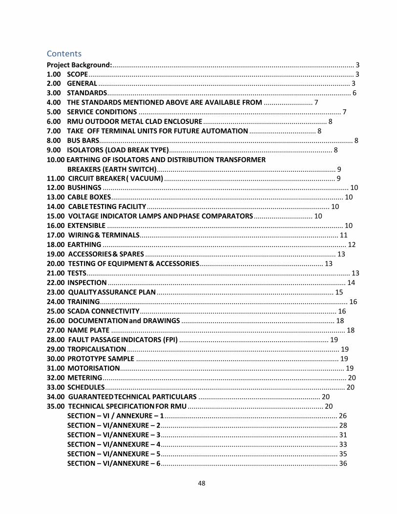
48
Contents Project Background:........................................................................................................................... 3 1.00 SCOPE....................................................................................................................................... 3 2.00 GENERAL ................................................................................................................................ 3 3.00 STANDARDS............................................................................................................................ 6 4.00 THE STANDARDS MENTIONED ABOVE ARE AVAILABLE FROM ......................... 7 5.00 SERVICE CONDITIONS ....................................................................................................... 7 6.00 RMU OUTDOOR METAL CLAD ENCLOSURE ............................................................... 8 7.00 TAKE OFF TERMINAL UNITS FOR FUTURE AUTOMATION .................................. 8 8.00 BUS BARS................................................................................................................................. 8 9.00 ISOLATORS (LOAD BREAK TYPE)................................................................................... 8 10.00 EARTHING OF ISOLATORS AND DISTRIBUTION TRANSFORMER
BREAKERS (EARTH SWITCH)........................................................................................... 9 11.00 CIRCUIT BREAKER ( VACUUM) ....................................................................................... 9 12.00 BUSHINGS ............................................................................................................................. 10 13.00 CABLE BOXES...................................................................................................................... 10 14.00 CABLE TESTING FACILITY ............................................................................................. 10 15.00 VOLTAGE INDICATOR LAMPS AND PHASE COMPARATORS .............................. 10 16.00 EXTENSIBLE ........................................................................................................................ 10 17.00 WIRING & TERMINALS..................................................................................................... 11 18.00 EARTHING ............................................................................................................................ 12 19.00 ACCESSORIES & SPARES ................................................................................................. 13 20.00 TESTING OF EQUIPMENT & ACCESSORIES............................................................... 13 21.00 TESTS...................................................................................................................................... 13 22.00 INSPECTION ......................................................................................................................... 14 23.00 QUALITY ASSURANCE PLAN .......................................................................................... 15 24.00 TRAINING.............................................................................................................................. 16 25.00 SCADA CONNECTIVITY.................................................................................................... 16 26.00 DOCUMENTATION and DRAWINGS .............................................................................. 18 27.00 NAME PLATE ....................................................................................................................... 18 28.00 FAULT PASSAGE INDICATORS (FPI) ............................................................................ 19 29.00 TROPICALISATION ............................................................................................................ 19 30.00 PROTOTYPE SAMPLE ....................................................................................................... 19 31.00 MOTORISATION.................................................................................................................. 19 32.00 METERING ............................................................................................................................ 20 33.00 SCHEDULES .......................................................................................................................... 20 34.00 GUARANTEED TECHNICAL PARTICULARS .............................................................. 20 35.00 TECHNICAL SPECIFICATION FOR RMU ..................................................................... 20
SECTION – VI / ANNEXURE – 1 ........................................................................................ 26 SECTION – VI/ANNEXURE – 2 .......................................................................................... 28 SECTION – VI/ANNEXURE – 3 .......................................................................................... 31 SECTION – VI/ANNEXURE – 4 .......................................................................................... 33 SECTION – VI/ANNEXURE – 5 .......................................................................................... 35 SECTION – VI/ANNEXURE – 6 .......................................................................................... 36
49
Project Background:-
The objective of the R-APDRP Project is to improve the reliability, efficiency, and loss
reduction of the Utility’s 11 kV distribution network. This is to be achieved by upgrading
and/or replacing existing overhead lines and underground cables, constructing additional
feeder segments and Ring Main Units (RMUs). The RMUs should be motorized and suitable
to be connected to F-RTU so as to be monitored and controlled through SCADA/DMS.
1.00 SCOPE
Design, Engineering, Manufacture, Assembly, Stage testing, Inspection and Testing before
supply, Packing and delivery at site, Erection, Installation, testing & Commissioning of
Outdoor type, SF6 gas filled 11 kV & 22 kV EXTENSIBLE / NON EXTENSIBLE Ring Main
units, with various combinations of Load Break Isolators & Circuit Breaker for Distribution
transformers center and feeders. The Ring Main units are to be installed in three phase,
three wire, 11kV or 22 kV, 50 Hz, A.C. Distribution network.
The RMUs should be provided with necessary take off terminal units for future automations
and all these units should be shielded in a outdoor metal-body for making them suitable for
outdoor use. The insulation/dielectric media inside the Non ferrite & Non magnetic grade
stainless steel welded tank should be SF6 gas. The RMUS should be of extensible type on
both sides.
34.1 This Specification provides for design, manufacture, inspection and testing before despatch,
packing and delivery F.O.R.(Destination) of SF6 insulated RMUs with necessary take off
terminal units for future automations, other accessories and auxiliaries equipments and
mandatory spares, described herein and required for their satisfactory operation.
34.2 The objective of the RMUs is for extremely small construction width, compact, maintenance
free, independent of climate, easy installation, operational reliability, Safe and easy
to operate, minimum construction cost, minimum site work and minimum space
requirement.
34.1 The RMUs shall conform in all respects to high standards Of Engineering design,
workmanship and latest revisions of relevant standards at the time of offer.
34.2 The type of the 11 KV and 22 KV circuit breaker shall be VCB and insulating medium for
load break isolators, Earth switch, 11 KV and 22 KV Buses and other associated equipments
should be SF6 gas.
2.1 GENERAL
The Ring Main Unit shall be installed at 11 KV and 22 KV junction points such as 200KVA,
315 kVA and 630 KVA Distribution transformer centers and feeders to have continuous
supply by isolating faulty sections. The RMU shall be extensible on both sides and consists
50
of the following combinations of load break switches and Circuit breakers for a nominal
voltage of 12 KV for 11 KV RMU and 24 KV For 22 KV RMU using SF6 gas as insulating and
Vacuum as arc quenching medium.
The RMU and combination shall be tropicalised and outdoor metal enclosed type with
minimum IP 54 protection. The RMU metal parts shall be of high thickness, high tensile steel
which must be grit/short blasted, thermally sprayed with Zinc alloy, phosphate or should
follow the 7 tank pre-treatment process and be subsequently painted with polyurethane
based powder paint. The overall paint layer thickness shall be not less than 80 microns.
Relevant IE rules for clearances, safety and operation inside the enclosure shall be
applicable. The complete Ring Main Unit shall be type tested at recognized laboratories by
National Accreditation Board of Testing and Calibration Laboratories (NABL) in India or
Abroad successfully.
All live parts except for the cable connections in the cable compartments shall be insulated
with SF6 gas. The SF6 gas filled main tank shall be Robotically welded Non ferrite & Non
magnetic grade stainless steel sheet of minimum 3 mm thickness, to have the best
weld quality and provided with a pressure relief arrangement away from operator. The SF6
gas pressure in the tank shall be constantly monitored by temperature compensating gas
pressure indicator offering a simple go , no- go indication. The gas pressure indictor shall be
provided having distinctive RED and GREEN zones for safe operation.
The SF6 gas tank shall be of completely sealed construction. The degree of protection
of main SF6 gas tank shall be IP 67. There shall be one Non-return valve to fill up the gas.
The connection of different welded sections of gas tank by gasket and bolts, to form a RMU
chamber is not acceptable. Oil or Air filled switchgear will not be considered.
The cable box of isolators and circuit breakers shall be from front/side/rear as per clause
no.13.
Any accidental over pressure inside the sealed chamber shall be limited by the opening of a
pressure-limiting device placed at top and rear end of the enclosure to release the SF6 Gas
away from operator and to ensure highest safety general public safety.
The Entire units of RMU shall be enclosed in a single compact metal clad, outdoor enclosure
with minimum IP 54 protection suitable for all weather conditions. The switchgear/steel
gas tank shall be filled with SF6 as per IEC/IS Standards relative pressure to ensure
the insulation and breaking functions. The steel gas tank must be sealed for life and shall
meet the “sealed pressure system” criteria in accordance with the IEC 298 standard. The
RMU must be a system for which no handling of gas is required throughout the 25 years of
service life. The manufacturer shall be guarantee for maximum leakage rate of SF6 gas will
be lower than 0.1 % per year. An absorption material such as activated alumina in the tank
shall be provided to absorb the moisture from the SF6 gas to regenerate the SF6 gas

51
following arc interruption.
The RMU shall have a design such that in the event of an internal arc fault, the operator
shall be safe. This should be in accordance with IEC 298 and relevant Test certificates shall
be submitted with the Tender.
The Complete RMU shall be tested for an internal arc rating of 20 kA for 3 Sec. for 11
KV and 16 KA for 3 sec for 22 KV System.
Suitable temperature rise test on the RMU shall be carried out & test reports shall
be submitted with tender for technical bid evaluation.
Each switchboard shall be identified by an appropriately sized label, which clearly indicates
the functional units and their electrical characteristics.
The switchgear and switchboard shall be designed so that the position of the different
devices is visible to the operator on the front of the switchboard and operations are visible
as well.
The entire system shall be totally encapsulated. There shall be no access to exposed
conductors. In accordance with the standards in effect, the switchboards shall be designed
so as to prevent access to all live parts during operation without the use of tools.
The entire 11 KV RMU and 22 KV RMU are insulated by inert gas (SF6) suitable for operating
voltage up to 12 KV and 24 kV respectively. The 11 KV/22 kV circuit breakers must be VCB
breaker.
The height of bottom of cable box shall be 310mm to provide the turning radius for HT cable
termination. The complete RMU Unit shall be provided with a pedestal made up of M.S.
Angle to mount the unit on plain surface.
All the RMUs must be routine tested for the following at factory in India:-
Micro-ohm test for the assembly inside the tank.
Circuit breaker analyzer test so as to ensure the simultaneous closing of all poles for
VCB.
SF6 gas leak test.
Partial Discharge test on the complete gas tank so as to be assure of the proper
insulation level and high product life.
High voltage withstands.
Secondary test to ensure the proper functioning of the live line indicators, fault
passage indicators and relays.
52
Sulphur Hex fluoride Gas (SF6 GAS)
The SF6 gas shall comply with IEC 376,376A, and 376B and shall be suitable in all respects
for use in 11 KV and 22 kV RMUs under the operating conditions. The SF6 shall be tested
for purity, dew point air hydrolysable fluorides and water content as per IEC 376,376A and
376B and test certificate shall be furnished to the owner indicating all the tests as per IEC
376 for each Lot of SF6 Gas.
3.00 STANDARDS
Unless otherwise specified elsewhere in this Specification, the RMU, Switchboard
(Switchgear), Load break isolators, Instrument Transformers and other associated
accessories shall conform to the latest revisions and amendments there of to the following
standards.
IEC 62 271-100/IEC 60 056/IS
1. IEC 60 298/IEC 62271-200/IS General requirement for Metal Enclosed 12729:1988 switchgear 2. IEC60129/IEC62271-102/IS 9921 Alternating current disconnector’s (Load
break isolators) and earthing switch
3. IEC 62271-100/IEC 60056/IS Specification for alternating current circuit
13118:1991IEC 62 271-200
breakers.
4. IEC 62 271-1/IEC 60694 Panel design, SF6/Vacuum Circuit
Breakers
5. IEC 60044-1/IEC 60185/IS 2705:1992 Current Transformer
6. IEC 60265/IS 9920:1981 High voltage switches
7. IEC 376 Filling of SF6 gas in RMU.
8. IEC 60273/IS :2099 Dimension of Indoor & Outdoor post
insulators with voltage > 1000 Volts.
9. IEC 60529/IS 13947(Part-1)- Degree of protection provided by
enclosures for low voltage switchgear
and control gear.
53
10. All Indian Electricity Rules/Bills amended upto date applicable for clearances,
safety and operation of equipment
Equipment meeting with the requirements of any other authoritative standards, which
ensures equal or better quality than the standard mentioned above shall also be
acceptable. If the equipments, offered by the Bidder conform to other standards, salient
points of difference between the standards adopted and the specific standards shall be
clearly brought out in relevant schedule. In case of any difference between provisions
of these standards and provisions of this specification, the provisions contained in this
specification shall prevail. One copy of such standards with authentic English Translations
shall be furnished along with the offer.(Hard copy)
4.00 THE STANDARDS MENTIONED ABOVE ARE AVAILABLE FROM: REFERENCE / ABBREVIATION NAME AND ADDRESS FROM WHICH THE STANDARDS ARE AVAILABLE
IEC INTERNATIONAL ELECTRO-TECHNICAL COMMISSION, BUREAU CENTRAL
DE LA COMMISSION, ELECTRO TECHNIQUE INTERNATIONAL, 1,
RUEDE VEREMBE, GENEVA, SWITZERLAND.
ISO INTERNATIONAL STANDARD ORGANISATION
SPECIFIC REQUIREMENTS IN RMU:-
The RMUs going to be installed in the field network will be hooked with SCADA through
RTUs and Hence, RMUs used shall be compatible with SCADA.
5.1 SERVICE CONDITIONS:
System Particulars:
1. Nominal system voltage 11 kV and 22 kV
2. Corresponding highest system voltage 12 kV and 24
3. Frequency 50 Hz ± 3 %
4. Number of phases 3
5. Neutral Earthing Solidly grounded
6. Fault level 20 kA for 3 sec for 11 kV RMU and 16
kA for 3 sec for 22kV RMU
54
The climatic conditions under which the equipment should operate satisfactory are as
under: Maximum ambient air temperature : 50 deg. C
Minimum ambient air temperature : 0 deg.C
Maximum humidity : 80% Altitude
above M.S.L. (maximum) : 1000 metres Average
annual rainfall 925 mm
Max. wind pressure : 200 Kg/m2
Seismic level (Horizontal accn.) : 0.3 g
Isoceraunic level : 50 Days per Year
Average thunder storm days : 50 days per annum
Reference ambient Temperature for temperature rise : 50 deg C
6.00 RMU OUTDOOR METAL CLAD ENCLOSURE.
The RMU enclosure must be a metallic; it shall follow an industrialized process of
manufacturing. The RMU and combination shall be tropicalised and outdoor metal enclosed
type. The RMU metal parts shall be of high thickness, high tensile steel which must be
grit/short blasted, thermally sprayed with Zinc alloy, phosphate or should follow the 7 tank
pre-treatment process and be subsequently painted with polyurethane based powder
paint. The overall paint layer thickness shall be not less than 80 microns. The enclosure shall
be of CRCA sheet of 3mm thickenss or galvanized of 1.6 mm thickness. The Outer enclosure
shall degree of protection IP54 (main door closed) and IP 41 (Main door opened).
The rating of enclosure shall be suitable for operation on three phase, three wire, 11 KV and
22 KV, 50 cycles, A.C. System with short-time current rating of 20KA for 3 seconds with
RMU Panels.
The enclosure should have two access doors one for the operation and relay monitoring
and other for the cable access. Both the doors should have the locking facility.
7.00 TAKE OFF TERMINAL UNITS FOR FUTURE AUTOMATION :
The RMU should be provided with necessary take off terminal units for future automations,
located in the front/rear accesses / LV cubical of the RMU.
8.00 BUS BARS:
The Bus shall be made of EC grade tinned copper of rating 630 A and shall be covered with
sleeve. The short time rating current shall be 20KA for 3 Sec for 11 kV and 16 KA for 3 Sec
55
for 22 kV. the bus bar connections shall be anti oxide greased.
9.00 ISOLATORS (LOAD BREAK TYPE):
The load break isolators for Incoming and Outgoing supply must be provided. These should
be fully insulated by SF6 gas. The load break isolators shall consist of 630 Amp fault
making/load breaking spring assisted ring switches, each with integral fault making earth
switches. The switch shall be mechanically interlocked to prevent the main and earth
switch being switched ‘ON’ at the same time. The selection of the main and earth switch is
made by a lever on the facia, which is allowed to move only if the main or earth switch is in
the off position. The ON –OFF operation of load break isolators should be through
SCADA remote operation. Each load break switch shall be of the triple pole, simultaneously
operated, non automatic type with quick break contacts and with integral earthing
arrangement.
The isolating distance between the OFF and the ON position in the isolator should be as per
IEC suitable for SF6 gas environment, so as to have enough isolating distance for ensuring
safety during DC injection for Cable testing.
The rated current of isolators shall be 630 A continuous at maximum ambient
temperature. No de-rating shall be allowed means at a maximum ambient
temperature of 50 deg C, isolator rating should be 630 A. The type test report to prove
the temperature rise below 55 deg C shall be submitted by the bidder with the offer.
10.00 EARTHING OF ISOLATORS AND DISTRIBUTION
TRANSFORMER BREAKERS (EARTH SWITCH).
Necessary arrangements are provided at Load break isolators / Distribution Transformer
Breaker for selecting Earth position. Mechanical interlocking systems shall prevent the RMU
function from being operated from the ‘ON’ to ‘Earth On’ position without going through
the
‘OFF’ position.
11.1 CIRCUIT BREAKER ( VACUUM)
The VCB breaker for the controlling of DT must be provided inside welded stainless steel
SF6 gas tank with the outdoor metal clad enclosure.
The breaker’s making & breaking current ratings at rated voltage shall be as follows:
(a) For 11kV System : Rated breaking capacity shall be 20 kA for 3 second.
: Rated making capacity shall be 50 kA for 3 second.
(b) For 22 kV System: Rated breaking capacity shall be 16 kA for 3 second.
: Rated making capacity shall be 40 kA for 3 second.
The VCB circuit breaker must be a spring assisted three positions with integral fault making
56
earth switch. The selection of the main/earth switch lever on the facia, which is allowed to
move only if the main or earth switches is in the off position.
The manual operation of the circuit breaker shall not have an effect on the trip spring. This
should only be discharged under a fault (electrical) trip; the following manual reset
operation should recharge the trip spring and reset the circuit breaker mechanism in the
main off position.
The circuit breaker shall be provided with self powered relay which have an electrical flag,
which shall operate in the event of a fault (electrical) trip occurring. The ‘tripped’ flag should
be an unambiguous colour differing from any other flag or mimic.
Both the circuit breaker and ring switches are operated by the same unidirectional
handle. The protection on the circuit breaker shall comprise of the following
components:-
- 3 NOS, 5P 10 class, protection CT’s (TAPE WOUND),
- A low burden trip coil and
- A self powered (No external DC or AC source required) IDMT protection relays
(Numeric/Micro processor based) 3 x over current and ONE earth fault element shall
be Definite Time type relay. The relay should also have rechargeable batteries. The relays
shall be of 1.3/3 second selectable IDMT characteristics with high set feature, the
O/C element current setting variable from 20 % to 200% of CT secondary ratings and E/F
element have current settings variable from 10 % to 80%. The protection curves and all
other settings shall be adjustable from touch panel. The protection system should be
suitable for protecting transformers of rated power from 250 KVA on wards. The relay
should be housed within a pilot cable box accessible.
12.00 BUSHINGS:
The RMU units are fitted with the standardized bolted type Bushings complying with IEC
standards and can be replaced at site. All the bushings are the same height from the
ground and are protected by a cable cover
13.00 CABLE BOXES:
All the cable boxes shall be air insulated suitable for dry type cable terminations and The
Cable entry can be from front / side / rear , as per the site requirements. The cable boxes at
each of the two ring switches should be suitable for accepting HV cables of sizes 3c x 300/3c
x 120 sq.mm and circuit breaker cable suitable up to 3c x 120 sq.mm. The cable boxes for an
isolator in it’s standard design should have sufficient space for connecting two cables per
phase. Necessary Right angle Boot should be supplied to the cable terminations. The cable
box shall be arc resistant as per IEC 62271- 200 amended uptodate. The clearances between
phase to phase and phase to earth shall be as per IEC 61243 -5 amended uptodate. The
57
cable termination and gland arrangement shall be appropriate for type and style of cables
used at the time.
14.00 CABLE TESTING FACILITY:
It shall be possible to test the cable after opening the cable boxes. The cable boxes should
open only after operation of the earth switch. Thus ensuring the earthing of the cables prior
to performing the cable testing with DC injection.
15.00 VOLTAGE INDICATOR LAMPS AND PHASE COMPARATORS
The RMU shall be equipped with a voltage indication to indicate whether or not there is
voltage on the cable. There should be a facility to check the synchronization of phases
with the use of external device. It shall be possible for the each of the function of the RMU
to be equipped with a permanent voltage indication as per IEC 601958 to indicate whether
or not there is voltage on the cables.
16.00 EXTENSIBLE
Each combination of RMU shall have the provision for extension on both sides by load break
isolators / breakers in future, with suitable accessories and necessary Bus Bar. Extensible
isolators and circuit breakers shall be individually housed in separate SF6 gas enclosures.
Multiple devices inside single gas tank / enclosure will not be acceptable. In case of
extensible circuit breakers, the Breaker should be capable of necessary short circuit
operations as per IEC at 20 KA for 3 Sec for 11 KV System and 16KA for 3 sec for 22 kV
system and the Breaker should have a rated current carrying capacity of 630 A.
17.00 WIRING & TERMINALS:
The wiring should be of high standard and should be able to withstand the tropical weather
conditions. All the wiring and terminals (including take off terminals for future automation,
DC, Control wiring), Spare terminals shall be provided by the contractor. The wiring cable
must be standard single-core non-sheathed, Core marking (ferrules), stripped with non-
notching tools and fitted with end sleeves, marked in accordance with the circuit
diagram with printed adhesive marking strips.
The wiring should be of high standard and should be able to withstand the tropical weather
conditions. All wiring shall be provided with single core multistrand copper conductor wires
with P.V.C insulation.
The wiring shall be carried out using multi-strand copper conductor super flexible PVC
insulated wires of 650/1100V Grade for AC Power, DC Control and CT circuits. Suitable
colored wires shall be used for phase identification and interlocking type ferrules shall be
provided at both ends of the wires for wire identification. Terminal should be
suitably protected to eliminate sulphating. Connections and terminal should be able to
withstand vibrations. The terminal blocks should be stud type for controls and disconnecting
link type terminals for CT leads with suitable spring washer and lock nuts.
58
Flexible wires shall be used for wiring of devices on moving parts such as swinging
Panels (Switch Gear) or panel doors. Panel wiring shall be securely supported, neatly
arranged readily accessible and connected to equipment terminals, terminal blocks
and wiring gutters. The cables shall be uniformly bunched and tied by means of PVC belts
and carried in a PVC carrying trough.
The position of PVC carrying trough and wires should not give any hindrance for fixing or
removing relay casing, switches etc., Wire termination shall be made with solder less
crimping type of tinned copper lugs. Core identification plastic ferrules marked to
correspond with panel wiring diagram shall be fitted with both ends of each wire.
Ferrules shall fit tightly on the wire when disconnected. The wire number shown on the
wiring shall be in accordance with the IS.375.
All wires directly connected to trip circuits of breaker or devices shall be distinguished by
addition of a red color unlettered ferrule.
Inter-connections to adjacent Panels (Switch Gear) shall be brought out to a separate set of
Terminal blocks located near the slots or holes to be provided at the top portion of the
panel. Arrangements shall be made for easy connections to adjacent Panels (Switch
Gear) at site and wires for this purpose shall be provided and bunched inside the panel. The
bus wire shall run at the top of the panel. Terminal block with isolating links should be
provided for bus wire. At least 10% of total terminals shall be provided as spare for
further connections. Wiring shall be done for all the contacts available in the relay and
other equipment and brought out to the terminal blocks for spare contacts. Color code for
wiring is preferable in the following colours.
Voltage supply Red, Yellow, Blue for phase and Black for Neutral
CT circuits similar to the above
DC circuits Grey for both positive and negative
250V AC circuits Red for phase and Black for neutral
Earthing Green
The wiring shall be in accordance to the wiring diagram for proper functioning of the
connected equipment. Terminal blocks shall not be less than 650V grade and shall be piece-
moulded type with insulation barriers.
The terminal shall hold the wires in the tight position by bolts and nuts with lock
washers. The terminal blocks shall be arranged in vertical formation at an inclined
angle with sufficient space between terminal blocks for easy wiring.
The terminals are to be marked with the terminal number in accordance with the circuit
59
diagram and terminal diagram. The terminals should not have any function designation and
are of the tension spring and plug-in type.
18.00 EARTHING:
The RMU outdoor metal clad, Switch Gear, Load break isolators, Vacuum circuit breakers
shall be equipped with an earth bus securely fixed along the base of the RMU.
The size of the earth bus shall be made of IEC/IS standards with tinned copper flat for
RMU and M.S. Flat for Distribution Transformer, earth spike and neutral earthing.
Necessary terminal clamps and connectors shall be included in the scope of supply.
All metal parts of the switchgear which do not belong to main circuit and which can collect
electric charges causing dangerous effect shall be connected to the earthing conductor
made of copper having CS area of minimum 75 mm . Each end of conductor shall be
terminated by M12/equivalent quality and type of terminal for connection to earth system
installation. Earth conductor location shall not obstruct access to cable terminations.
The following items are to be connected to the main earth conductor by rigid or copper
conductors having a minimum cross section of 75 mm (a) earthing switches (b)
Cable sheath or screen (c) capacitors used in voltage control devices, if any.
The metallic cases of the relays, instruments and other panel mounted Equipment’s shall be
connected to the earth bus by independent copper wires of size shall be made of IEC/IS
standards. The colour code of earthing wire shall be green. Earthing wires shall be
connected on the terminals with suitable clamp connectors and soldering shall not be
permitted.
19.1 ACCESSORIES & SPARES:
The following spares and accessories shall be supplied along with the main equipments
at free of costs. This shall not be included in the price schedule.
(a) Charging lever for operating load break isolators & circuit breaker of each RMU.
(b) The pressure gauges indications – 1 numbers
Provision shall be made for padlocking the load break switches/ Circuit breaker, and
the earthing switches in either open or closed position with lock & master key.
20.00 TESTING OF EQUIPMENT & ACCESSORIES:
Provision for testing CTs, Relays, Breakers and Cables shall be made available. Procedure
and schedule for Periodical & Annual testings of equipments, relays, etc. shall be
provided by the supplier.
21.1 TESTS:
21.2 TYPE TESTS:
60
The Tenderers should, along with the tender documents, submit copies of all Type test
certificate of their make in full shape as confirming to relevant ISS/IEC of latest issue
obtained from a International/National Govt. Lab/Recognized laboratory, within the last 5
(five) years from the date of offer. The list of type tests as follows:
(1) Short time current withstand test and peak current withstand test.
(2) Lightening .Impulse voltage with-stand test
(3) Temperature rise test.
(4) Short Circuit current making and breaking tests.
(5) Power frequency voltage withstand test (dry).
(6) Capacitive current switching test confirming to IEC.
(7) Mechanical operation test.
(8) Measurement of the resistance of the main circuit.
(9) Degree of protection of main tank and outer enclosure
(10) Switch, circuit breaker, earthing switch making capacity.
(11) Switch, circuit breaker breaking capacity.
(12) Internal arc withstand.
(13) Checking of partial discharge on SF6 gas tank.
The above type test certificates should accompany the drawings for the materials duly
signed by the institution that has type test certificate.
21.3 ACCEPTANCE AND ROUTINE TESTS:
All acceptance and routine tests as stipulated in the latest IEC- shall be carried out by the
supplier in the presence of Board’s representative. The supplier shall give at least 7 days
advance intimation to the Board to enable them to depute their representative for
witnessing the tests. The routine tests are as follows:
(1) Conformity with drawings and diagrams,
(2) Measurement of closing and opening
speeds, (3) Measurement of operating torque,
(4) Checking of filling pressure,
(5) Checking of gas-tightness,
61
(6) Dielectric testing and main circuit resistance
measurement. (7) Power frequency voltage
(8) Resistance test for the circuit
(9) Mechanical operation tests.
The partial discharge shall be carried out as routine test on each and every completely
assembled RMU gas tank and not on a sample basis. As this test checks and guarantees
for the high insulation level and thus the complete life of switchgear.
21.4 ADDITIONAL TESTS:
The Board reserves the right for carrying out any other tests of a reasonable nature at the
works of the supplier/laboratory or at any other recognized laboratory/research institute in
addition to the above mentioned type, acceptance and routine tests at the cost of the Board
to satisfy that the material complies with the intent of this specification.
21.5 PRE-COMMISSIONING TESTS:
All the pre-commissioning tests will be carried out in the presence of the Board testing
engineer and necessary drawing manual and periodical test tools shall be arranged to be
supplied.
During the above tests the contractor’s representative should be present till the RMUs are put
in to service.
22 INSPECTION:
The inspection may be carried out by the Board at any stage of manufacture. The supplier
shall grant free access to Board’s representative at a reasonable time when the work is in
progress. Inspection and acceptance of any equipment under this specification by the Board
shall not relieve the supplier of his obligation of furnishing equipment in accordance with
the specification and shall not prevent subsequent rejection if the equipment is found to be
defective.
The supplier shall keep the Board informed in advance, about the manufacturing
programme so that arrangement can be made for inspection. The Board reserves the right
to insist for witnessing the acceptance/routine testing of the bought out items. The Board
has rights to inspect the supplier’s premises for each and every consignment for type &
routine test.
No material shall be dispatched from its point of manufacture unless the material has been
satisfactorily inspected and tested / unless the same is waived by the Board in writing.
23 QUALITY ASSURANCE PLAN:
The bidder shall invariably furnish following information along with his offer / in case of
62
event of order.
(i) Statement giving list of important raw materials including but not limited to
(b) Contact material
(c) Insulation
(d) Sealing material
(e) Contactor, limit switches, etc. in control cabinet.
Name of sub-suppliers for the raw materials, list of standards according to which the raw
materials are tested, list of test normally carried out on raw materials in presence of
Bidder’s representative, copies of test certificates.
(ii) Information and copies of test certificates as in (i) above in respect of bought out
accessories.
(iii) List of areas in manufacturing process, where stage inspections are normally carried
out for quality control and details of such tests and inspections.
(iv) Special features provided in the equipment to make it maintenance free.
(v) List of testing equipment available with the Bidder for final testing of RMUs and
associated combinations vis-à-vis, the type, special, acceptance and routine tests
specified in the relevant standards. These limitations shall be very clearly brought
out in the relevant schedule i.e. schedule of deviations from specified test
requirements. The supplier shall within 15 days from the date of receipt of Purchase
Order submit following information to the Board.
a) List of raw materials as well bought out accessories and the names of sub-suppliers
selected from those furnished along with offer.
b) Necessary test certificates of the raw material and bought out accessories.
c) Quality Assurance Plan (QAP) with hold points for Board’s inspection. The quality
assurance plan and hold points shall be discussed between the Board and supplier
before the QAP is finalized.
The supplier shall submit the routine test certificates of bought out items and raw material,
at the time of routine testing of the fully assembled breaker.
24 TRAINING:
The supplier shall give rigorous training to the engineers & staff at the site for 2 days
in attending trouble shooting and maintenance, at free of cost.
25 SCADA CONNECTIVITY:
63
- SPECIFIC REQUIREMENT FOR SCADA CONNECTIVITY
A) Following DMS requirement shall specifically be mentioned in RMU Specifications
may be separate section with name “ Specific Requirement for Automation” can be
added :
1. FPI shall be provided per isolator
2. DC control supply system should be 24VDC.
3. Battery charger to cater load of minimum 10 motorised operation cycles (CLOSE-OPEN)
in absence of battery.
4. Battery to cater load of minimum 10 motorised operation cycles (CLOSE-OPEN) in
absence of battery charger. The battery backup should be minimum of 6 Hrs
5. Availability of MCB's for battery charger supply, RMU Motor supply & FRTU supply
(Minimum 2 Amp circuit for future use of FRTU).
6. Individual control circuit of isolator/CB/BC to have point of isolation/protection.
7. Individual motor circuit of isolator/CB/BC to have point of isolation/protection.
8. RMU shall have minimum protection of IP54 for C&R section with gland plate & knock
outs. Provision for control cable entry should preferably be from Right/ Left top through
LV cable box & shall be independent of HV isolator/CB/BC status. It should be vermin
proof.
9. Control cable gland plate shall be independent of power cable gland plate.
10. A point of earthing for control cables shall be electrically isolated from power cable
earthing.
11. Ambient temperature of 50 degree C max. Allowable temperature rise of battery &
battery charger above ambient 40 degree C
12. Local / Remote switch shall be provided on all the isolator & breaker panels for
selection of controls
13. CT & PT terminals for all the circuit breakers only.
B) Following is the list of I/O requirements for RMU modules. Please note that all DI & DO
should be potential free contacts.
a) List of potential free contacts for Isolator (Terminals shall be provided):
Digital Indications
1. Isolator ON --02 No. & 2 NC
2. Isolator OFF --02 No. & 2 NC
3. Isolator Earth switch Status (ON/OFF)
64
4. FPI Operated
5. LOCAL/REMOTE switch position
List of commands
1. Isolator Close
2. Isolator Open
3. FPI reset
b) List of potential free Contacts for Circuit Breakers / Bus Coupler (Terminals shall be
provided)
Digital Indications
1. Circuit Breaker ON
2. Circuit Breaker OFF
3. Auto Trip
4. LOCAL/REMOTE switch position
List of commands
1. Circuit Breaker Close
2. Circuit Breaker Open
c) Requirement of Multifunction Meters (MFMs)
Terminals shall be provided for CT and PT Connections
Space may be provided for MFM mounting inside control panel
26 DOCUMENTATION and DRAWINGS:
All drawings shall conform to relevant International Standards Organization (ISO)
Specification. All drawings shall be in ink and suitable for microfilming.
The tenderer shall submit along with his tender dimensional general arrangement
drawings of the equipments, illustrative and descriptive literature in triplicate for various
items in the RMUs which are all essentially required for future automation.
i) Schematic diagram of the RMU panel
ii) Instruction manuals
iii) Catalogues of spares recommended with drawing to indicate each items of
spares iv) List of spares and special tools recommended by the supplier.
v) Copies of Type Test Certificates as per latest IS/IEC.
65
vi) Drawings of equipments, relays, control wiring circuit, etc.
vii) Foundation drawings of RMU and D.T.Structure.
viii) Dimensional drawings of each material used for item Vii.
ix) Actual single line diagram of RMU/RMUs with or without Extra combinations shall be
made displayed on the front portion of the RMU so as to carry out the operations
easily.
The following should be supplied to each consignee circle along with the initial supply of the
equipments ordered. 2 copies of printed and bound volumes of operation, maintenance and
erection manuals in English along with the copies of approved drawings and type
test reports etc. 2 sets of the manuals as above shall be supplied to the Chief
Engineer/Distribution. A soft copy of the all Technical and Drawing furnished in a CD.
27 NAME PLATE:
Each RMU and its associated equipments shall be provided with a nameplate legible
and indelibly marked with at least the following information.
(a) Name of manufacturer
(b) Type, design and serial number
(c) Rated voltage and current
(d) Rated frequency
(e) Rated symmetrical breaking capacity
(f) Rated making capacity
(g) Rated short time current and its duration
(h) Purchase Order number and date
(i) Month and Year of supply
(j) Rated lighting impulse withstand voltage
(k) Feeder name (Incoming and Out going), DTs Structure name, 11000Volts
(l) Dangers etc.
NOTE:
i) The word rated need not appear on the name plate. Recognized abbreviations may be
used to express the above particulars.
ii) Whether the circuit breaker is fitted with closing / tripping devices necessitating an
auxiliary supply shall be stated either on the circuit breaker name plate or any
66
other acceptable position.
28 FAULT PASSAGE INDICATORS (FPI):
These shall facilitate quick detection of faulty section of line. The fault indication may be on
the basis of monitoring fault current flow through the device. The unit should be self-
contained requiring no auxiliary power supply. The FPI shall be integral part of RMU. The
FPI shall have LCD/LED display, automatic reset facility. The sensors to be bushing
mounted. FPI shall be provided per isolator
29 TROPICALISATION:
Due regard should be given to the climatic conditions under which the equipment is to work.
Ambient temperature normally varies between 0 C and 50 C. The climate is humid
and rapid variations occur, relative humidity between 60% and 90% being frequently
recorded, but these values generally correspond to the lower ambient temperatures. The
equipment should also be designed to prevent ingrees of vermin, accidental contact with
live parts and to minimize the ingress of dust and dirt. The use of materials which may be
liable to attack by termites and other insects should be avoided.
30 PROTOTYPE SAMPLE:
The successful bidder should manufacture 3 Nos of Prototype RMUs as per the specification
and keep ready at their works for the purpose of sample inspection and testing. The
MSEDCL at their option may send a team of Engineers to the works. Prior intimation of this
inspection may not be given to the bidder.
31 MOTORISATION:
All the functions within the RMU i.e Isolators / Breakers should be fitted with motor
mechanism and closing coil making it suitable to make it on from remote.
Control Supply and Auxiliaries: Following Auxiliaries has to be considered other):- i.
Shunt Trip Coil -24 V DC for Isolators and Breakers.
ii. Closing Coil – 24 VDC
iii. Motor Mechanism – 24 VDC
iv. 2 NO + 2 NC – Potential free auxiliary contacts for breakers / isolators
v. Auxiliary Power supply should be – 24 VDC
vi. Battery & Battery Charger with the battery backup of at least 6 Hour
vii. Local / Remote Switch for breaker and isolators
32 METERING:
Separate Metering Module Consisting of Bus connected PTs and metering CTs to be
provided for VCB function along with provision of installing Multifunction meter to be

67
provided. The PTs and CTs provided shall be made up of epoxy cast resin Ring Core type
with an accuracy class of 0.5S & The CT of 5 Amp. Secondary. The CT ratio shall as per
transformer rating. The metering is required only in breaker functions.
33 SCHEDULES
33.1 The Tenderer shall fill in the following schedule’s which is part and parcel o fteh tender
specifications and offer. If the Schedules are not submitted duly filled in with the offer , the
offer shall be liable for rejection.
Schedule ‘A’ (Annexure 1 to 6) ……….. Guaranteed and technical Particulars
Schedule ‘B’ ……………………………. Schedule of Tenderer’s Experience
33.2 Any Additional information may be furnished separately by the tenderer, if necessary.
34 GUARANTEED TECHNICAL PARTICULARS:
The Bidder should fill up the details in schedule A – ‘Guaranteed technical Particulars and
the statement such as “as per drawing enclosed “, “As per MSEDCL requirement”, “as per
IS”, “as per specification” etc shall be considered as details not furnished and such offers will
be rejected.
35 TECHNICAL SPECIFICATION FOR RMU A) 11 KV
RMU
I. 11KV Bus Bar
Current Carrying Capacity : 630 Amps.
Short time rating current for 3 secs. : 20 KA
Insulation of bus bar : SF6
Bus bar connections : Anti-oxide grease
II. Parameters for Circuit Breaker and Load break isolators
Type : Metal enclosed
No of Phases 3
No. of poles 3
Rated voltage : 12 KV
Operating voltage : 11 KV (+10% to –20%)
Rated lightning impulse withstand voltage : 75 KV
Rated power frequency withstand voltage : 28 KV
Insulating gas : SF6
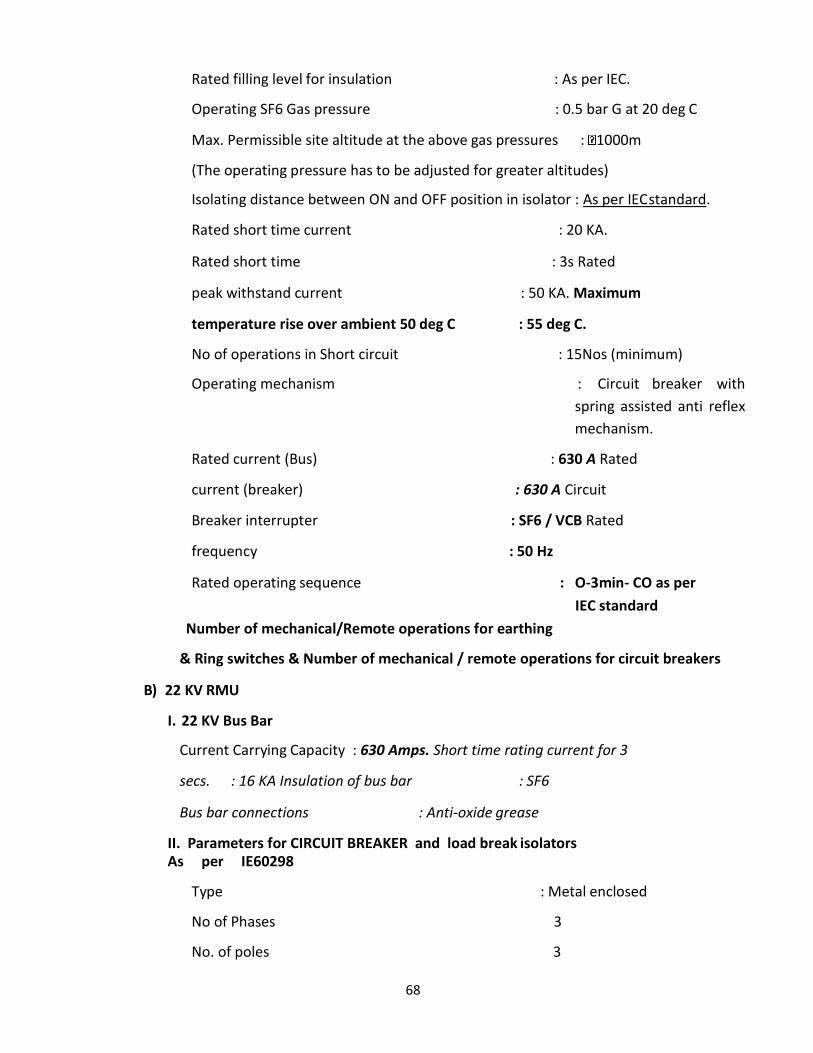
68
Rated filling level for insulation : As per IEC.
Operating SF6 Gas pressure : 0.5 bar G at 20 deg C
Max. Permissible site altitude at the above gas pressures : 1000m
(The operating pressure has to be adjusted for greater altitudes)
Isolating distance between ON and OFF position in isolator : As per IEC standard.
Rated short time current : 20 KA.
Rated short time : 3s Rated
peak withstand current : 50 KA. Maximum
temperature rise over ambient 50 deg C : 55 deg C.
No of operations in Short circuit : 15Nos (minimum)
Operating mechanism : Circuit breaker with
spring assisted anti reflex
mechanism.
Rated current (Bus) : 630 A Rated
current (breaker) : 630 A Circuit
Breaker interrupter : SF6 / VCB Rated
frequency : 50 Hz
Rated operating sequence : O-3min- CO as per
IEC standard
Number of mechanical/Remote operations for earthing
& Ring switches & Number of mechanical / remote operations for circuit breakers
B) 22 KV RMU
I. 22 KV Bus Bar
Current Carrying Capacity : 630 Amps. Short time rating current for 3
secs. : 16 KA Insulation of bus bar : SF6
Bus bar connections : Anti-oxide grease
II. Parameters for CIRCUIT BREAKER and load break isolators As per IE60298
Type : Metal enclosed
No of Phases 3
No. of poles 3
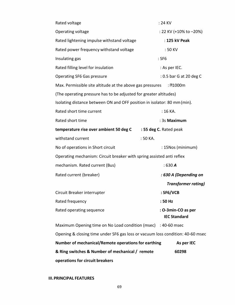
69
Rated voltage : 24 KV
Operating voltage : 22 KV (+10% to –20%)
Rated lightening impulse withstand voltage : 125 kV Peak
Rated power frequency withstand voltage : 50 KV
Insulating gas : SF6
Rated filling level for insulation : As per IEC.
Operating SF6 Gas pressure : 0.5 bar G at 20 deg C
Max. Permissible site altitude at the above gas pressures : 1000m
(The operating pressure has to be adjusted for greater altitudes)
Isolating distance between ON and OFF position in isolator: 80 mm (min).
Rated short time current : 16 KA.
Rated short time : 3s Maximum
temperature rise over ambient 50 deg C : 55 deg C. Rated peak
withstand current : 50 KA.
No of operations in Short circuit : 15Nos (minimum)
Operating mechanism: Circuit breaker with spring assisted anti reflex
mechanism. Rated current (Bus) : 630 A
Rated current (breaker) : 630 A (Depending on
Transformer rating)
Circuit Breaker interrupter : SF6/VCB
Rated frequency : 50 Hz
Rated operating sequence : O-3min-CO as per
IEC Standard
Maximum Opening time on No Load condition (msec) : 40-60 msec
Opening & closing time under SF6 gas loss or vacuum loss condition: 40-60 msec
Number of mechanical/Remote operations for earthing As per IEC
& Ring switches & Number of mechanical / remote 60298
operations for circuit breakers
III. PRINCIPAL FEATURES
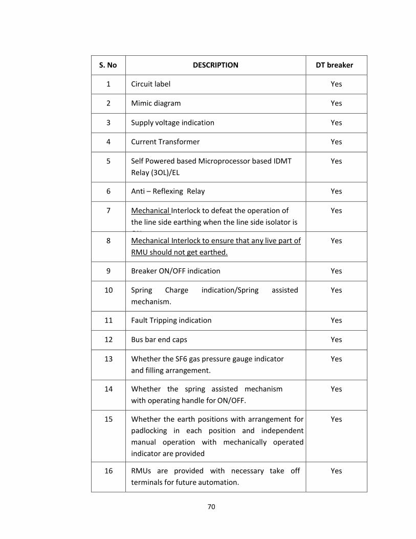
70
S. No
DESCRIPTION
DT breaker
1
Circuit label
Yes
2
Mimic diagram
Yes
3
Supply voltage indication
Yes
4
Current Transformer
Yes
5
Self Powered based Microprocessor based IDMT
Relay (3OL)/EL
Yes
6
Anti – Reflexing Relay
Yes
7
Mechanical Interlock to defeat the operation of
the line side earthing when the line side isolator is
ON.
Yes
8
Mechanical Interlock to ensure that any live part of
RMU should not get earthed.
Yes
9
Breaker ON/OFF indication
Yes
10
Spring Charge indication/Spring assisted
mechanism.
Yes
11
Fault Tripping indication
Yes
12
Bus bar end caps
Yes
13
Whether the SF6 gas pressure gauge indicator
and filling arrangement.
Yes
14
Whether the spring assisted mechanism
with operating handle for ON/OFF.
Yes
15
Whether the earth positions with arrangement for
padlocking in each position and independent
manual operation with mechanically operated
indicator are provided
Yes
16
RMUs are provided with necessary take off
terminals for future automation.
Yes
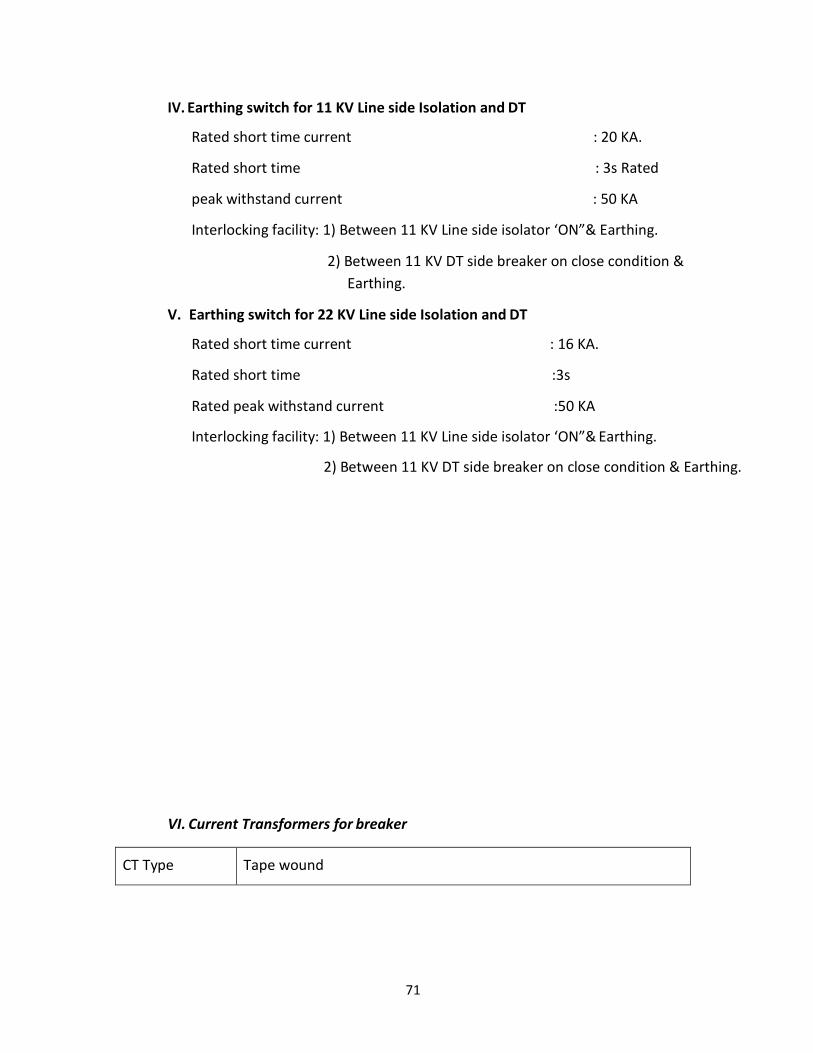
71
IV. Earthing switch for 11 KV Line side Isolation and DT
Rated short time current : 20 KA.
Rated short time : 3s Rated
peak withstand current : 50 KA
Interlocking facility: 1) Between 11 KV Line side isolator ‘ON”& Earthing.
2) Between 11 KV DT side breaker on close condition &
Earthing.
V. Earthing switch for 22 KV Line side Isolation and DT
Rated short time current : 16 KA.
Rated short time :3s
Rated peak withstand current :50 KA
Interlocking facility: 1) Between 11 KV Line side isolator ‘ON”& Earthing.
2) Between 11 KV DT side breaker on close condition & Earthing.
VI. Current Transformers for breaker
CT Type
Tape wound

72
CT Description
The CTs of DT breaker shall be suitable for sensing the minimum
primary variable as per Transformer rating and standardized
ratio i.e. 5/5, 10/5, 25/5, 50/5, 100/5,
etc. and the secondary current for the CT is 5 A. The CT shall be
housed in outside SF6 chamber for testing and Maintenance
Accuracy Class
class 5P10 for protection and 0.5S for metering.
Rated burden
Suitable for self powered relay
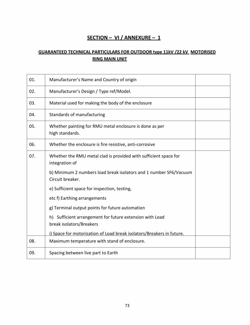
73
SECTION – VI / ANNEXURE – 1
GUARANTEED TECHNICAL PARTICULARS FOR OUTDOOR type 11kV /22 kV MOTORISED
RING MAIN UNIT
01.
Manufacturer’s Name and Country of origin
02.
Manufacturer’s Design / Type ref/Model.
03.
Material used for making the body of the enclosure
04.
Standards of manufacturing
05.
Whether painting for RMU metal enclosure is done as per
high standards.
06.
Whether the enclosure is fire resistive, anti-corrosive
07.
Whether the RMU metal clad is provided with sufficient space for
integration of
b) Minimum 2 numbers load break isolators and 1 number SF6/Vacuum
Circuit breaker.
e) Sufficient space for inspection, testing,
etc f) Earthing arrangements
g) Terminal output points for future automation
h) Sufficient arrangement for future extension with Load
break isolators/Breakers
i) Space for motorization of Load break isolators/Breakers in future.
08.
Maximum temperature with stand of enclosure.
09.
Spacing between live part to Earth
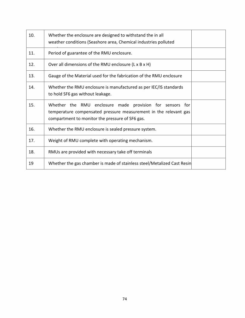
74
10.
Whether the enclosure are designed to withstand the in all
weather conditions (Seashore area, Chemical industries polluted
area)
11.
Period of guarantee of the RMU enclosure.
12.
Over all dimensions of the RMU enclosure (L x B x H)
13.
Gauge of the Material used for the fabrication of the RMU enclosure
14.
Whether the RMU enclosure is manufactured as per IEC/IS standards
to hold SF6 gas without leakage.
15.
Whether the RMU enclosure made provision for sensors for
temperature compensated pressure measurement in the relevant gas
compartment to monitor the pressure of SF6 gas.
16.
Whether the RMU enclosure is sealed pressure system.
17.
Weight of RMU complete with operating mechanism.
18.
RMUs are provided with necessary take off terminals
19
Whether the gas chamber is made of stainless steel/Metalized Cast Resin
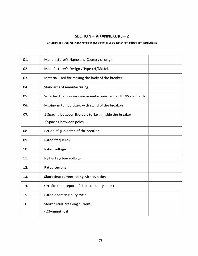
75
SECTION – VI/ANNEXURE – 2
SCHEDULE OF GUARANTEED PARTICULARS FOR DT CIRCUIT BREAKER
01.
Manufacturer’s Name and Country of origin
02.
Manufacturer’s Design / Type ref/Model.
03.
Material used for making the body of the breaker
04.
Standards of manufacturing
05.
Whether the breakers are manufactured as per IEC/IS standards
06.
Maximum temperature with stand of the breakers
07.
1)Spacing between live part to Earth inside the breaker
2)Spacing between poles
08.
Period of guarantee of the breaker
09.
Rated frequency
10.
Rated voltage
11.
Highest system voltage
12.
Rated current
13.
Short time current rating with duration
14.
Certificate or report of short circuit type test
15.
Rated operating duty cycle
16.
Short circuit breaking current
(a)Symmetrical
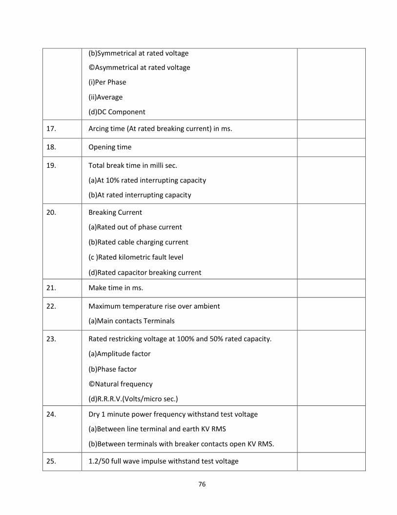
76
(b)Symmetrical at rated voltage
©Asymmetrical at rated voltage
(i)Per Phase
(ii)Average
(d)DC Component
17.
Arcing time (At rated breaking current) in ms.
18.
Opening time
19.
Total break time in milli sec.
(a)At 10% rated interrupting capacity
(b)At rated interrupting capacity
20.
Breaking Current
(a)Rated out of phase current
(b)Rated cable charging current
(c )Rated kilometric fault level
(d)Rated capacitor breaking current
21.
Make time in ms.
22.
Maximum temperature rise over ambient
(a)Main contacts Terminals
23.
Rated restricking voltage at 100% and 50% rated capacity.
(a)Amplitude factor
(b)Phase factor
©Natural frequency
(d)R.R.R.V.(Volts/micro sec.)
24.
Dry 1 minute power frequency withstand test voltage
(a)Between line terminal and earth KV RMS
(b)Between terminals with breaker contacts open KV RMS.
25.
1.2/50 full wave impulse withstand test voltage

77
(a)Between line terminal and earth KVp.
(b)Between terminals with breaker contacts open KVp.
26.
SF6 /VCB interrupter make
27.
Contact separation distance
28.
Type of main contacts
29.
Contact pressure
30.
Contact resistance
31.
Life of the interrupter (in number of operations)
32.
(i)Tripping at rated current
(ii)Tripping at maximum fault current.
(Allowable maximum erotion 3 mm)
(iii)Mechanical operations.
33.
Details of main contacts making contact with the breaker
truck with the panel
34.
Control circuit voltage AC/DC.
35.
Whether trip free or not
36.
Whether all the interlocks provided

78
SECTION – VI/ANNEXURE – 3
SCHEDULE OF GUARANTEED PARTICULARS FOR LOAD BREAK ISOLATORS & EARTHING
ARRANGEMENTS
SL.
DESCRIPTION
ISOLATORS
EARTHING
SWITCH
FOR DT &
ISOLATOR
01.
Manufacturer’s Name and Country of origin
02.
Manufacturer’s Design / Type ref/Model.
03.
Material used for making the body of
the isolators .
04.
Standards of manufacturing
05.
Whether the isolators & earth positions
are manufactured as per IEC/IS standards
06.
Maximum temperature with stand of
the isolators & earth switches
07.
1) Spacing between live part to Earth
2) Spacing between fixed and moving contacts
in the open position.
08.
Period of guarantee of the isolators
09.
Rated frequency
10.
Rated voltage
11.
Highest system voltage

79
12.
Rated current
13.
Short time current rating with duration
14.
Certificate or report of short circuit type test
15.
Rated operating duty cycle
16.
Short circuit breaking current
17.
Arcing time (At rated breaking current) in ms.
18.
Opening time
19
Whether all the Mechanical interlocks
provided.
20
Whether Sufficient arrangements are made to
operate the isolators through SCADA in
future, also to be ensured for provision of
space for accommodation of motor in future
21
Fault passage indicator
1)Type/Model
2)Self powered Yes/No
3)Current readings
4)Fault currents
5)Phase currents
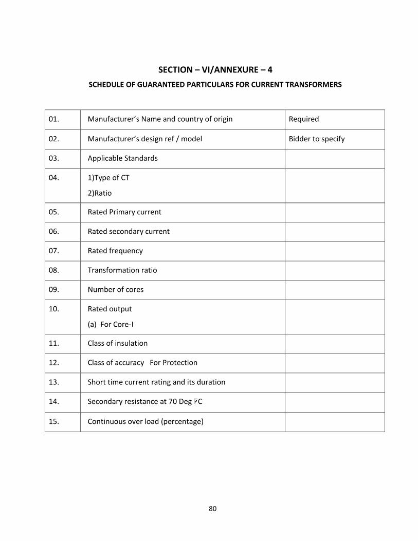
80
SECTION – VI/ANNEXURE – 4
SCHEDULE OF GUARANTEED PARTICULARS FOR CURRENT TRANSFORMERS
01.
Manufacturer’s Name and country of origin
Required
02.
Manufacturer’s design ref / model
Bidder to specify
03.
Applicable Standards
04.
1)Type of CT
2)Ratio
05.
Rated Primary current
06.
Rated secondary current
07.
Rated frequency
08.
Transformation ratio
09.
Number of cores
10.
Rated output
(a) For Core-I
11.
Class of insulation
12.
Class of accuracy For Protection
13.
Short time current rating and its duration
14.
Secondary resistance at 70 Deg C
15.
Continuous over load (percentage)

81
16.
One minute power frequency dry withstand voltage
17.
1.2/50 micro sec. impulse withstand test voltage
18.
One minute power frequency withstand test voltage
on secondary
19.
Instrument safety factor
20.
Type of primary winding
21.
Literature/leaflets pamphlets about the current
transformer offered
22.
Period of guarantee

82
SECTION – VI/ANNEXURE – 5
SHEDULE OF GUARANTEED TECHNICAL PARTICULARS FOR SELF POWERED MICRO
PROCESSOR BASED NUMERICAL RELAYS
01.
Manufacturer’s Name and Country of origin
02.
Manufacturer’s design / Ref. Type
03.
Applicable Standards
04.
Current Setting range for
(a)Over current relay
(b)Earth fault Element
IDMT
Definite Time
05.
Whether the relay has the in-built facilities of IDMT, OL, EL
06.
Details of IDMT Characteristics
07.
Accuracy for different settings and limits of errors
08.
Whether Alpha numeric / LED display
09.
Whether compatible for 1 A CT Secondary
10.
Whether draw out type
11.
Types of case
12.
Reset time
13.
Burden of relay
14.
Maximum and Minimum, operating ambient air temp.
15.
Whether technical literature pamphlets about the relay offered.
16.
Period of guarantee.
17.
Certificate of Proof for Electro Magnetic Interference.
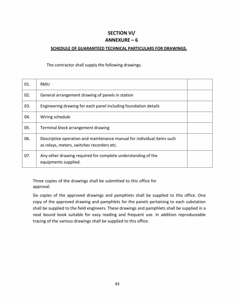
83
SECTION VI/
ANNEXURE – 6
SCHEDULE OF GUARANTEED TECHNICAL PARTICULARS FOR DRAWINGS.
The contractor shall supply the following drawings.
01.
RMU
02.
General arrangement drawing of panels in station
03.
Engineering drawing for each panel including foundation details
04.
Wiring schedule
05.
Terminal block arrangement drawing
06.
Descriptive operation and maintenance manual for individual items such
as relays, meters, switches recorders etc.
07.
Any other drawing required for complete understanding of the
equipments supplied.
Three copies of the drawings shall be submitted to this office for approval.
Six copies of the approved drawings and pamphlets shall be supplied to this office. One
copy of the approved drawing and pamphlets for the panels pertaining to each substation
shall be supplied to the field engineers. These drawings and pamphlets shall be supplied in a
neat bound book suitable for easy reading and frequent use. In addition reproduceable
tracing of the various drawings shall be supplied to this office.
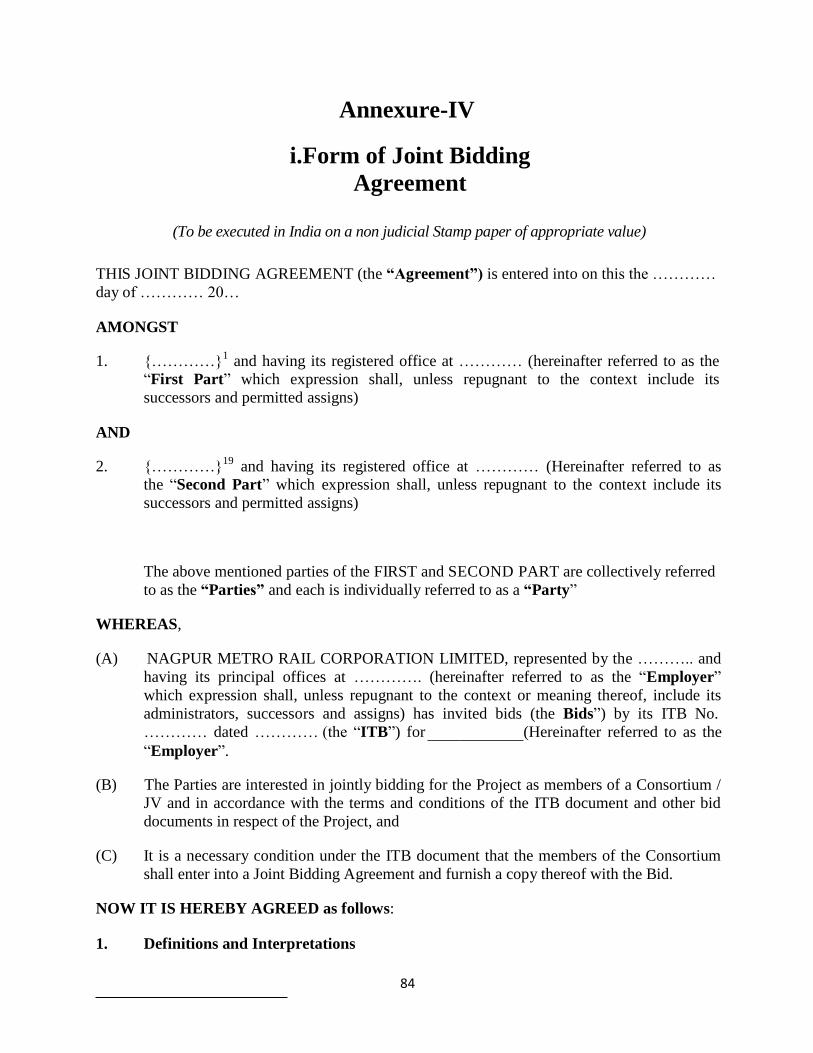
84
Annexure-IV
i.Form of Joint Bidding
Agreement
(To be executed in India on a non judicial Stamp paper of appropriate value)
THIS JOINT BIDDING AGREEMENT (the “Agreement”) is entered into on this the …………
day of ………… 20… AMONGST
1. {…………}1
and having its registered office at ………… (hereinafter referred to as the
“First Part” which expression shall, unless repugnant to the context include its
successors and permitted assigns) AND
2. {…………}19
and having its registered office at ………… (Hereinafter referred to as
the “Second Part” which expression shall, unless repugnant to the context include its
successors and permitted assigns)
The above mentioned parties of the FIRST and SECOND PART are collectively referred
to as the “Parties” and each is individually referred to as a “Party” WHEREAS,
(A) NAGPUR METRO RAIL CORPORATION LIMITED, represented by the ……….. and
having its principal offices at …………. (hereinafter referred to as the “Employer”
which expression shall, unless repugnant to the context or meaning thereof, include its
administrators, successors and assigns) has invited bids (the Bids”) by its ITB No.
………… dated ………… (the “ITB”) for
“Employer”.
(Hereinafter referred to as the
(B) The Parties are interested in jointly bidding for the Project as members of a Consortium /
JV and in accordance with the terms and conditions of the ITB document and other bid
documents in respect of the Project, and (C) It is a necessary condition under the ITB document that the members of the Consortium
shall enter into a Joint Bidding Agreement and furnish a copy thereof with the Bid. NOW IT IS HEREBY AGREED as follows:
1. Definitions and Interpretations

85
1 The members of the JV/Consortium to fill in their name and the relevant law and the jurisdiction of incorporation.
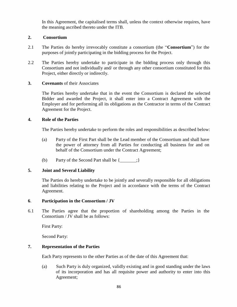
86
In this Agreement, the capitalised terms shall, unless the context otherwise requires, have
the meaning ascribed thereto under the ITB. 2. Consortium
2.1 The Parties do hereby irrevocably constitute a consortium (the “Consortium”) for the
purposes of jointly participating in the bidding process for the Project. 2.2 The Parties hereby undertake to participate in the bidding process only through this
Consortium and not individually and/ or through any other consortium constituted for this
Project, either directly or indirectly. 3. Covenants of their Associates
The Parties hereby undertake that in the event the Consortium is declared the selected
Bidder and awarded the Project, it shall enter into a Contract Agreement with the
Employer and for performing all its obligations as the Contractor in terms of the Contract
Agreement for the Project. 4. Role of the Parties
The Parties hereby undertake to perform the roles and responsibilities as described below:
(a) Party of the First Part shall be the Lead member of the Consortium and shall have
the power of attorney from all Parties for conducting all business for and on behalf of the Consortium under the Contract Agreement;
(b) Party of the Second Part shall be { ;}
5. Joint and Several Liability
The Parties do hereby undertake to be jointly and severally responsible for all obligations
and liabilities relating to the Project and in accordance with the terms of the Contract
Agreement. 6. Participation in the Consortium / JV
6.1 The Parties agree that the proportion of shareholding among the Parties in the
Consortium / JV shall be as follows:
First Party:
Second Party: 7. Representation of the Parties
Each Party represents to the other Parties as of the date of this Agreement that:
(a) Such Party is duly organized, validly existing and in good standing under the laws
of its incorporation and has all requisite power and authority to enter into this
Agreement;

87
(b) The execution, delivery and performance by such Party of this Agreement has
been authorized by all necessary and appropriate corporate or governmental
action and a copy of the extract of the charter documents and board resolution/
power of attorney in favour of the person executing this Agreement for the
delegation of power and authority to execute this Agreement on behalf of the
Consortium Member is annexed to this Agreement, and will not, to the best of its
knowledge:
(i) require any consent or approval not already obtained;
(ii) violate any applicable law presently in effect and having applicability to it;
(iii) violate the memorandum and articles of association, by-laws or other
applicable organizational documents thereof;
(iv) violate any clearance, permit, concession, grant, license or other
governmental authorization, approval, judgment, order or decree or any
mortgage agreement, indenture or any other instrument to which such
Party is a party or by which such Party or any of its properties or assets are
bound or that is otherwise applicable to such Party; or
(v) create or impose any liens, mortgages, pledges, claims, security interests,
charges or encumbrances or obligations to create a lien, charge, pledge,
security interest, encumbrances or mortgage in or on the property of such
Party, except for encumbrances that would not, individually or in the
aggregate, have a material adverse effect on the financial condition or
prospects or business of such Party so as to prevent such Party from
fulfilling its obligations under this Agreement;
(c) this Agreement is the legal and binding obligation of such Party, enforceable in
accordance with its terms against it; and
(d) there is no litigation pending or, to the best of such Party's knowledge, threatened
to which it or any of its affiliates is a party that presently affects or which would
have a material adverse effect on the financial condition or prospects or business
of such Party in the fulfillment of its obligations under this Agreement. 8. Termination
This Agreement shall be effective from the date hereof and shall continue in full force
and effect until the completion of the Project is achieved under and in accordance with
the Contract Agreement, in case the Project is awarded to the Consortium. However, in
case the Consortium does not get selected for award of the Project, the Agreement will
stand terminated upon return of the Bid Security by the Employer to the Bidder, as the
case may be. 9. Miscellaneous
9.1 This Joint Bidding Agreement shall be governed by laws of {India}.
88
9.2 The Parties acknowledge and accept that this Agreement shall not be amended by the
Parties without the prior written consent of the Employer. IN WITNESS WHEREOF THE PARTIES ABOVE NAMED HAVE EXECUTED AND
DELIVERED THIS AGREEMENT AS OF THE DATE FIRST ABOVE WRITTEN.
SIGNED, SEALED AND DELIVERED SIGNED, SEALED AND DELIVERED
For and on behalf of
LEAD MEMBER by: SECOND PART
(Signature) (Signature)
(Name) (Name)
(Designation) (Designation)
(Address) (Address)
Notes:
1. The mode of the execution of the Joint Bidding Agreement should be in accordance
with the procedure, if any, laid down by the applicable law and the charter
documents of the executant(s) and when it is so required, the same should be under
common seal affixed in accordance with the required procedure.
2. Each Joint Bidding Agreement should attach a copy of the extract of the charter
documents and documents such as resolution / power of attorney in favour of the
person executing this Agreement for the delegation of power and authority to
execute this Agreement on behalf of the Consortium Member.
89
ii.Form of Legal Capacity / Power of
Attorney (Refer ITB20.2)
(To be forwarded on the letterhead of the Bidder/ Lead Member of Consortium)
Ref. Date:
To,
***********
***********
Dear Sir,
We hereby confirm that we/ our members in the Consortium (constitution of which has been
described in the bid) satisfy the terms and conditions laid out in the ITB document.
We have agreed that …………………… (insert member’s name) will act as the Lead Member of
our consortium.*
We have agreed that ………………….. (insert individual’s name) will act as our representative/
will act as the representative of the consortium on its behalf* and has been duly authorized to
submit the bid. Further, the authorised signatory is vested with requisite powers to furnish such
letter and authenticate the same.
Thanking you,
Yours faithfully,
(Signature, name and designation of the authorised signatory)
For and on behalf of……………………………..
*Please strike out whichever is not applicable.

90
iii.Power of Attorney for signing of
Bid
Know all men by these presents, We…………………………………………….. (name of the firm
and address of the registered office) do hereby irrevocably constitute, nominate, appoint and authorise
Mr/ Ms (name), …………………… son/daughter/wife of ……………………………… and
presently residing at …………………., who is presently employed with us/ the Lead Member of our
Consortium and holding the position of ……………………………. , as our true and lawful attorney
(hereinafter referred to as the “Attorney”) to do in our name and on our behalf, all such acts, deeds
and things as are necessary or required in connection with or incidental to submission of our bid for
the ***** Project proposed by the ***** (the “Employer”) including but not limited to signing and
submission of all applications, bids and other documents and writings, participate in pre-bid meetings
and other conferences and providing information/ responses to the Employer, representing us in all
matters before the Employer, signing and execution of all contracts including the Contract Agreement
and undertakings consequent to acceptance of our bid, and generally dealing with the Employer in all
matters in connection with or relating to or arising out of our bid for the said Project and/ or upon
award thereof to us and/or till the entering into of the Contract Agreement with the Employer.
AND we hereby agree to ratify and confirm and do hereby ratify and confirm all acts, deeds and
things done or caused to be done by our said Attorney pursuant to and in exercise of the powers
conferred by this Power of Attorney and that all acts, deeds and things done by our said Attorney in
exercise of the powers hereby conferred shall and shall always be deemed to have been done by us.
IN WITNESS WHEREOF WE, …………………………., THE ABOVE NAMED PRINCIPAL
HAVE EXECUTED THIS POWER OF ATTORNEY ON THIS ……… DAY OF …………. 2014.
Signature of the Authorized Representative:
Initial of the Authorized Representative:
Signed before me and the signature is
attested
For …………………………..
(Signature, name, designation and address)
Witnesses:
1.
(Notarised)
2.
91
Accepted
……………………………
(Signature)
(Name, Title and Address of the Attorney)
Notes:
The mode of execution of the Power of Attorney should be in accordance with the procedure, if
any, laid down by the applicable law and the charter documents of the executant(s) and when it
is so required, the same should be under common seal affixed in accordance with the required
procedure. Wherever required, the Bidder should submit for verification the extract of the charter documents
and documents such as a board or shareholders’ resolution/ power of attorney in favour of the
person executing this Power of Attorney for the delegation of power hereunder on behalf of the
Bidder. For a Power of Attorney executed and issued overseas, the document will also have to be
legalised by the Indian Embassy and notarised in the jurisdiction where the Power of Attorney is
being issued. However, the Power of Attorney provided by bidder/members of the Consortium
from countries that have signed the Hague Legislation Convention 1961 are not required to be
legalised by the Indian Embassy if it carries a conforming Appostille certificate.
92
iv.Power of Attorney for Lead Member of
Consortium
Whereas the ***** (“the Employer”) has invited applications from interested parties for the *****
Project (the “Project”).
Whereas, …………………….., …………………….., …………………….. and
…………………….. (collectively the “Consortium”) being Members of the Consortium are
interested in bidding for the Project in accordance with the terms and conditions of the Instruction to
Bidders (ITB) and other connected documents in respect of the Project, and
Whereas, it is necessary for the Members of the Consortium to designate one of them as the Lead
Member with all necessary power and authority to do for and on behalf of the Consortium, all acts,
deeds and things as may be necessary in connection with the Consortium’s bid for the Project and its
execution.
NOW THEREFORE KNOW ALL MEN BY THESE PRESENTS
We, …………………….. having our registered office at …………………….., M/s.
…………………….. having our registered office at ……………………..,(hereinafter
collectively referred to as the “Principals”) do hereby irrevocably designate, nominate,
constitute, appoint and authorise M/S …………………….. having its registered office at
…………………….., being one of the Members of the Consortium, as the Lead Member and
true and lawful attorney of the Consortium (hereinafter referred to as the “Attorney”). We hereby
irrevocably authorise the Attorney (with power to sub-delegate) to conduct all business for and
on behalf of the Consortium and any one of us during the bidding process and, in the event the
Consortium is awarded the concession/contract, during the execution of the Project and in this
regard, to do on our behalf and on behalf of the Consortium, all or any of such acts, deeds or
things as are necessary or required or incidental to the pre-qualification of the Consortium and
submission of its bid for the Project, including but not limited to signing and submission of all
applications, bids and other documents and writings, participate in bidders and other
conferences, respond to queries, submit information/ documents, sign and execute contracts and
undertakings consequent to acceptance of the bid of the Consortium and generally to represent
the Consortium in all its dealings with the Employer in all matters in connection with or relating
to or arising out of the Consortium’s bid for the Project and/or upon award thereof for all
obligations and liabilities relating to the Project and in accordance with the terms of the Contract
Agreement.
AND hereby agree to ratify and confirm and do hereby ratify and confirm all acts, deeds and things
done or caused to be done by our said Attorney pursuant to and in exercise of the powers conferred by
this Power of Attorney and that all acts, deeds and things done by our said Attorney in exercise of the
powers hereby conferred shall and shall always be deemed to have been done by us/ Consortium.
IN WITNESS WHEREOF WE THE PRINCIPALS ABOVE NAMED HAVE EXECUTED THIS
POWER OF ATTORNEY ON THIS …………………. DAY OF ……….

93
2..…
94
For ……………………..
(Signature)
……………………..
(Name & Title)
For ……………………..
(Signature)
……………………..
(Name & Title)
Accepted:
Witnesses:
1.
2.
………………………………………
(Executants)
(To be executed by all the Members of the Consortium)
Notes:
The mode of execution of the Power of Attorney should be in accordance with the procedure, if
any, laid down by the applicable law and the charter documents of the executant(s) and when it
is so required, the same should be under common seal affixed in accordance with the required
procedure. Also, wherever required, the Bidder should submit for verification the extract of the charter
documents and documents such as a board or shareholders’ resolution/ power of attorney in
favour of the person executing this Power of Attorney for the delegation of power hereunder on
behalf of the Bidder. For a Power of Attorney executed and issued overseas, the document will also have to be
legalised by the Indian Embassy and notarised in the jurisdiction where the Power of Attorney is
being issued. However, the Power of Attorney provided by Applicants from countries that have
signed the Hague Legislation Convention 1961 are not required to be legalised by the Indian
Embassy if it carries a conforming Appostille certificate.

95
Tender Index
The Bidder shall include with his Tender an index which cross refers all of the Employer's tender
requirements elaborated in Bid Documents to all the individual sections within Technical Package and
Financial Package which the Bidder intends to be the responses to each and every one of those
requirements.
The Bid submitted must be clearly presented, all pages numbered and aid out in a logical sequence with
main and subheadings to facilitate evaluation.