Embed Size (px)
Citation preview

ANSI/AGMA 2004---B89(Revision of AGMA 240.01)
January 1989Reaffirmed October 1995
AMERICAN NATIONAL STANDARD
Gear Materials and Heat Treatment Manual

Gear Materials and Heat Treatment Manual
2004---B89iiANSI/AGMA
Gear Materials And Heat Treatment ManualAGMA 2004---B89(Revision of AGMA 240.01)
[Tables or other self---supporting sections may be quoted or extracted in their entirety. Credit lines shouldread: Extracted from AGMA 2004---B89, Gear Materials and Heat Treatment Manual, with the permission of thepublisher, the American Gear Manufacturers Association, 1500 King Street, Suite 201, Alexandria, Virginia22314.]
AGMA Standards are subject to constant improvement, revision or withdrawal as dictated by experience.Any person who refers to an AGMA Technical Publication should be sure that the publication is the latest avail-able from the Association on the subject matter.
ABSTRACT
The Gear Materials and Heat Treatment Manual provides information pertaining to engineering materialsand material treatments used in gear manufacture. Topics included are definitions, selection guidelines, heattreatment, quality control, life considerations and a bibliography. The material selection includes ferrous, non-ferrous and nonmetallic materials. Wrought, cast, and fabricated gear blanks are considered. The heat treat-ment section includes data on through hardened, flame hardened, induction hardened, carburized, carboni-trided, and nitrided gears. Quenching, distortion, and shot peeningare discussed. Quality control is discussed asrelated to gear blanks, process control, and metallurgical testing on the final products.
Copyright E, 1989Reaffirmed October 1995
American Gear Manufacturers Association1500 King Street, Suite 201Alexandria, Virginia 22314
February 1989
ISBN: 1---55589---524---7

Gear Materials and Heat Treatment Manual
2004---B89iiiANSI/AGMA
FOREWORD
[The foreword, footnotes, and appendices, if any, are provided for informational purposes only and shouldnot be construed as part of AGMA Standard 2004---B89 (Formerly 240.01), Gear Materials and Heat TreatmentManual.]
The Standard provides a broad range of information on gear materials and their heat treatment. It is in-tended to assist the designer, process engineer, manufacturer and heat treater in the selection and processing ofmaterials for gearing. Data contained herein represents a consensus from metallurgical representatives of mem-ber companies of AGMA.
This Standard replaces AGMA 240.01, October 1972. The first draft of AGMA 240.01, Gear MaterialsManual, was prepared in October 1966. It was approved by the AGMA membership in March 1972. Reprintingof AGMA 240.01 for distribution was discontinued in 1982 because it had been decided in 1979 by the Metallur-gy and Materials Committee to revise its format. The initial draft of AGMA 2004---B89 (formerly 240.01) wascompleted in April, 1983. Work continued on the Standard with numerous additional revised drafts within theMetallurgy and Materials Committee until it was balloted in 1988. It was completed and approved by theAGMA Technical Division Executive Committee in September 1988 and on January 23, 1989 it was approved asan American National Standard.
Suggestions for the improvement of this standard will be welcome. They should be sent to the AmericanGear Manufacturers Association, 1500 King Street, Suite 201, Alexandria, Virginia 22314.

Gear Materials and Heat Treatment Manual
2004---B89ivANSI/AGMA
PERSONNEL of the AGMA Committee for Metallurgy And Materials
Chairman: L. E. Arnold (Xtek, Inc.)Vice Chairman: G. J. Wiskow (Falk)
ACTIVE MEMBERS
M. Abney (Fairfield Manufacturing)R. J. Andreini (Earle M. Jorgensen)E. S. Berndt (C and M of Indiana)J. Bonnet (WesTech)N. K. Burrell (Metal Improvement Co. Inc.)R. J. Cunningham (Boeing)P. W. Early, Jr. (Gleason)A. Giammarise (General Electric)J. P. Horvath (G. M. Chevrolet --- Muncie)J. Bruce Kelly (General Motors)D. R. McVittie (The Gear Works --- Seattle)
N. P. Milano (Regal Beloit Corporation)A. G. Milburn (The Gear Works --- Seattle)P. Rivart (CLECIM)R. H. Shapiro (Arrow Gear)W. L. Shoulders (Reliance Electric) (Deceased)M. Starozhitsky (Outboard Marine)A. A. Swiglo (IPSEN)S. Tipton (Caterpillar)D. Vukovich (Eaton)L. L. Witte (General Motors)
ASSOCIATE MEMBERS
T. Bergquist (Western Gear)J. D. Black (General Motors)E. R. Carrigan (Emerson Electric)P. E. Cary (Metal Finishing)H. B. Gayley (IMO Delaval)J. F. Craig (Cummins Engine)T. C. Glew (Prager)D. K. Guttshall (IMO Delaval)W. H. Heller (Peerless Winsmith)D. L. Hillman (Westinghouse, Air Brake)B. A. Hoffmann (Dresser)L. D. Houck (Mack Trucks)A. J. Lemanski (Sikorsky)
R. L. Leslie (SPECO Corporation)B. L. Mumford (Alten Foundry)G. E. Olson (Cleveland)J. R. Partridge (Lufkin)E. M. Rickt (Auburn Gear)H. I. Sanderow (Supermet)R. L. Schwettman (Xtek, Inc.)L. J. Smith (Invincible Gear)Y. Sueyoshi (Tsubakimoto Chain)M. Tanaka (Nippon Gear)R. E. Vaglia (Farrel Connecticut)T. L. Winterrowd (Cummins Engine)

Gear Materials and Heat Treatment Manual
2004---B89vANSI/AGMA
Table of ContentsSection Title Page
1. Scope 1. . . . . . . . . . . . . . . . . . . . . . . . . . . . . . . . . . . . . . . . . . . . . . . . . . . . . . . . . . . . . . . . . . . . . . . . . . .
2. References and Information 1. . . . . . . . . . . . . . . . . . . . . . . . . . . . . . . . . . . . . . . . . . . . . . . . . . . . . . . .
2.1 References 1. . . . . . . . . . . . . . . . . . . . . . . . . . . . . . . . . . . . . . . . . . . . . . . . . . . . . . . . . . .2.2 Information Sources 2. . . . . . . . . . . . . . . . . . . . . . . . . . . . . . . . . . . . . . . . . . . . . . . . . . .
3. Definitions 2. . . . . . . . . . . . . . . . . . . . . . . . . . . . . . . . . . . . . . . . . . . . . . . . . . . . . . . . . . . . . . . . . . . . . . .
4. Materials Selection Guidelines 5. . . . . . . . . . . . . . . . . . . . . . . . . . . . . . . . . . . . . . . . . . . . . . . . . . . . . .
4.1 Mechanical Properties 5. . . . . . . . . . . . . . . . . . . . . . . . . . . . . . . . . . . . . . . . . . . . . . . . .4.2 Grade and Heat Treatment 6. . . . . . . . . . . . . . . . . . . . . . . . . . . . . . . . . . . . . . . . . . . . .4.3 Cleanliness 7. . . . . . . . . . . . . . . . . . . . . . . . . . . . . . . . . . . . . . . . . . . . . . . . . . . . . . . . . . .4.4 Dimensional Stability 7. . . . . . . . . . . . . . . . . . . . . . . . . . . . . . . . . . . . . . . . . . . . . . . . . .4.5 Cost and Availability 7. . . . . . . . . . . . . . . . . . . . . . . . . . . . . . . . . . . . . . . . . . . . . . . . . .4.6 Hardenability 8. . . . . . . . . . . . . . . . . . . . . . . . . . . . . . . . . . . . . . . . . . . . . . . . . . . . . . . .4.7 Machinability 9. . . . . . . . . . . . . . . . . . . . . . . . . . . . . . . . . . . . . . . . . . . . . . . . . . . . . . . .4.8 Ferrous Gearing 9. . . . . . . . . . . . . . . . . . . . . . . . . . . . . . . . . . . . . . . . . . . . . . . . . . . . . .4.9 Selection Criteria for Wrought, Cast, or Fabricated Steel Gearing 19. . . . . . . . . . . .4.10 Copper Base Gearing 19. . . . . . . . . . . . . . . . . . . . . . . . . . . . . . . . . . . . . . . . . . . . . . . . . .4.11 Other Non---Ferrous Materials 25. . . . . . . . . . . . . . . . . . . . . . . . . . . . . . . . . . . . . . . . . .4.12 Non---Metallic Materials 25. . . . . . . . . . . . . . . . . . . . . . . . . . . . . . . . . . . . . . . . . . . . . . .
5. Heat Treatment 25. . . . . . . . . . . . . . . . . . . . . . . . . . . . . . . . . . . . . . . . . . . . . . . . . . . . . . . . . . . . . . . . . . .
5.1 Through Hardening Processes 26. . . . . . . . . . . . . . . . . . . . . . . . . . . . . . . . . . . . . . . . . .5.2 Flame and Induction Hardening 28. . . . . . . . . . . . . . . . . . . . . . . . . . . . . . . . . . . . . . . . .5.3 Carburizing 34. . . . . . . . . . . . . . . . . . . . . . . . . . . . . . . . . . . . . . . . . . . . . . . . . . . . . . . . . .5.4 Carbonitriding 38. . . . . . . . . . . . . . . . . . . . . . . . . . . . . . . . . . . . . . . . . . . . . . . . . . . . . . . .5.5 Nitriding 39. . . . . . . . . . . . . . . . . . . . . . . . . . . . . . . . . . . . . . . . . . . . . . . . . . . . . . . . . . . .5.6 Other Heat Treatments 41. . . . . . . . . . . . . . . . . . . . . . . . . . . . . . . . . . . . . . . . . . . . . . . .5.7 Quenching 42. . . . . . . . . . . . . . . . . . . . . . . . . . . . . . . . . . . . . . . . . . . . . . . . . . . . . . . . . . .5.8 Distortion 42. . . . . . . . . . . . . . . . . . . . . . . . . . . . . . . . . . . . . . . . . . . . . . . . . . . . . . . . . . .5.9 Shot Peening 47. . . . . . . . . . . . . . . . . . . . . . . . . . . . . . . . . . . . . . . . . . . . . . . . . . . . . . . . .5.10 Residual Stress Effects 51. . . . . . . . . . . . . . . . . . . . . . . . . . . . . . . . . . . . . . . . . . . . . . . . .
6. Metallurgical Quality Control 52. . . . . . . . . . . . . . . . . . . . . . . . . . . . . . . . . . . . . . . . . . . . . . . . . . . . . . .
6.1 Incoming Material Quality Control 52. . . . . . . . . . . . . . . . . . . . . . . . . . . . . . . . . . . . . .6.2 Incoming Material Hardness Tests 52. . . . . . . . . . . . . . . . . . . . . . . . . . . . . . . . . . . . . . .6.3 Incoming Material Mechanical Tests 53. . . . . . . . . . . . . . . . . . . . . . . . . . . . . . . . . . . . .6.4 Heat Treat Process Control 53. . . . . . . . . . . . . . . . . . . . . . . . . . . . . . . . . . . . . . . . . . . . .6.5 Part Characteristics 55. . . . . . . . . . . . . . . . . . . . . . . . . . . . . . . . . . . . . . . . . . . . . . . . . . .6.6 Metallurgical, Mechanical and Non---Destructive Tests and Inspections 56. . . . . . . .6.7 Microstructure 61. . . . . . . . . . . . . . . . . . . . . . . . . . . . . . . . . . . . . . . . . . . . . . . . . . . . . . .6.8 Mechanical Property Test Bar Considerations 63. . . . . . . . . . . . . . . . . . . . . . . . . . . . .
Bibliography 64. . . . . . . . . . . . . . . . . . . . . . . . . . . . . . . . . . . . . . . . . . . . . . . . . . . . . . . . . . . . . . . . . . . . . . . . .

Gear Materials and Heat Treatment Manual
2004---B89viANSI/AGMA
Table of ContentsSection Title Page
Appendices
Appendix A Plastic Gear Materials 65. . . . . . . . . . . . . . . . . . . . . . . . . . . . . . . . . . . . . . . . . . . . . . . .Appendix B Approximate Maximum Controlling Section Size Considerations for
Through Hardened Gearing 67. . . . . . . . . . . . . . . . . . . . . . . . . . . . . . . . . . . . . . . . . . .Appendix C Case Hardenability of Carburizing Steels 69. . . . . . . . . . . . . . . . . . . . . . . . . . . . . . . . .Appendix D Service Life Considerations 70. . . . . . . . . . . . . . . . . . . . . . . . . . . . . . . . . . . . . . . . . . . . .
Tables
Table 4---1 Typical Gear Materials --- Wrought Steel 6. . . . . . . . . . . . . . . . . . . . . . . . . . . . . . . . . .Table 4---2 Typical Brinell Hardness Ranges and Strengths for Annealed,
Normalized & Tempered Steel Gearing 7. . . . . . . . . . . . . . . . . . . . . . . . . . . . . . . . . .Table 4---3 Typical Brinell Hardness Ranges and Strengths for Quenched
and Tempered Steel Gearing 8. . . . . . . . . . . . . . . . . . . . . . . . . . . . . . . . . . . . . . . . . . .Table 4---4 Machinability of Common Gear Materials 10. . . . . . . . . . . . . . . . . . . . . . . . . . . . . . . .Table 4---5 Mechanical Property Requirements --- Cold Drawn, Stress Relieved
Steel Bars (Special Cold Drawn, High Tensile) 11. . . . . . . . . . . . . . . . . . . . . . . . . . .Table 4---6 Typical Chemical Analyses for Though Hardened Cast Steel Gears 14. . . . . . . . . . .Table 4---7 Tensile Properties of Through Hardened Cast Steel Gears 14. . . . . . . . . . . . . . . . . . .Table 4---8 Minimum Hardness and Tensile Strength Requirements for Gray Cast Iron 16. . .Table 4---9 Mechanical Properties of Ductile Iron 17. . . . . . . . . . . . . . . . . . . . . . . . . . . . . . . . . . . .Table 4---10 Chemical Analyses of Wrought Bronze Alloys 22. . . . . . . . . . . . . . . . . . . . . . . . . . . . .Table 4---11 Typical Mechanical Properties of Wrought Bronze Alloy Rod and Bar 22. . . . . . . . .Table 4---12 Chemical Analyses of Cast Bronze Alloys 23. . . . . . . . . . . . . . . . . . . . . . . . . . . . . . . . .Table 4---13 Mechanical Properties of Cast Bronze Alloys 24. . . . . . . . . . . . . . . . . . . . . . . . . . . . . .
Table 5---1 Test Bar Size for Core Hardness Determination 35. . . . . . . . . . . . . . . . . . . . . . . . . . .Table 5---2 Typical Effective Case Depth Specifications for Carburized Gearing 38. . . . . . . . . .Table 5---3 Approximate Minimum Core Hardness of Carburized Gear Teeth 39. . . . . . . . . . . .Table 5---4 Approximate Minimum Surface Hardness --- Nitrided Steels 41. . . . . . . . . . . . . . . . .Table 5---5 Commonly Used Quenchants for Ferrous Gear Materials 43. . . . . . . . . . . . . . . . . . .Table 5---6 Typical Shot Size and Intensity for Shot Peening 50. . . . . . . . . . . . . . . . . . . . . . . . . . .

Gear Materials and Heat Treatment Manual
2004---B89viiANSI/AGMA
Table of ContentsSection Title Page
Figures
Fig 4---1 Typical Design of Cast Steel Gears 13. . . . . . . . . . . . . . . . . . . . . . . . . . . . . . . . . . . . . . .Fig 4---2 Directionality of Forging Properties 20. . . . . . . . . . . . . . . . . . . . . . . . . . . . . . . . . . . . . .
Fig 5---1 Variation in Hardening Patterns Obtainable onGear Teeth by Flame Hardening 29. . . . . . . . . . . . . . . . . . . . . . . . . . . . . . . . . . . . . . .
Fig 5---2 Variations in Hardening Patterns Obtainable onGear Teeth by Induction Hardening 30. . . . . . . . . . . . . . . . . . . . . . . . . . . . . . . . . . . .
Fig 5---3 Recommended Maximum Surface Hardness and Effective Case DepthHardness Versus Percent Carbon for Flame and Induction Hardening 33. . . . . . .
Fig 5---4 General Design Guidelines for Blanks for Carburized Gearing 45. . . . . . . . . . . . . . .Fig 5---5 Typical Distortion Characteristics of Carburized Gearing 46. . . . . . . . . . . . . . . . . . . .Fig 5---6 Shot Peening Intensity Control 48. . . . . . . . . . . . . . . . . . . . . . . . . . . . . . . . . . . . . . . . . .Fig 5---7 Residual Stress by Peening 1045 Steel at 62 HRC with 330 Shot 49. . . . . . . . . . . . . .Fig 5---8 Depth of Compressive Stress Versus Almen Intensity for Steel 50. . . . . . . . . . . . . . .
Fig 6---1 Circular (Head Shot) Magnetic Particle Inspection 58. . . . . . . . . . . . . . . . . . . . . . . . .Fig 6---2 Coil Shot Magnetic Particle Inspection 59. . . . . . . . . . . . . . . . . . . . . . . . . . . . . . . . . . .Fig 6---3 Ultrasonic Inspection Oscilloscope Screen 61. . . . . . . . . . . . . . . . . . . . . . . . . . . . . . . .Fig 6---4 Distance---Amplitude Reference Line for Ultrasonic Inspection 62. . . . . . . . . . . . . .

Gear Materials and Heat Treatment Manual
2004---B89viiiANSI/AGMA
(This page is intentionally left blank)

Gear Materials and Heat Treatment Manual
2004---B891ANSI/AGMA
1. Scope
This Manual was developed to provide basic in-formation and recommend sources of additional in-formation pertaining to gear materials, their treat-ments, and other considerations related to themanufacture and use of gearing.
Metallurgical aspects of gearing as related to rat-ing (allowable sac and sat values) are not included,but, are covered in AGMA rating standards.
2. References and Information
2.1 References.
Abbreviations are used in the references to spe-cific documents in this Standard. The abbreviationsinclude: AGMA, American Gear ManufacturersAssociation; ASNT, American Society of Nonde-structive Testing; ASTM, American Society for Test-ing Materials; SAE, Society of Automotive Engi-neers.
The following documents contain provisionswhich, through reference in this Standard, constituteprovisions of this document. At the time of publica-tion, the editions were valid. Allpublications are sub-ject to revision, and the users of this Standard are en-couraged to investigate the possibility of applying themost recent editions of the publications listed.
AGMA 141.01---1984, Plastics Gearing ---Molded, Machined, And Other Methods, A Report onthe State of the Art
AGMA 2001---B88, Fundamental Rating FactorsandCalculation Methods for Involute Spur andHelicalGear Teeth
AGMA 6033---A88, Standard for Marine Propul-sion Gear Units, Part 1 Materials
ANSI/AGMA 6034---A88, Practice for Single andDouble Reduction Cylindrical---Worm and Helical---Worm Speed Reducers
ASNT---TC---1A (June 80), Recommended Prac-tice by American Society for Nondestructive Testing
ASTM A48---83, Specification for Gray Iron Cast-ings
ASTM A148---84, Steel Castings, HighStrength, for Structural Purposes
ASTM A220---76, Specification for Pearlitic Mal-leable Iron Castings
ASTM A255---67, Method for End---Quench Testfor Hardenability of Steel
ASTM A290---82, Carbon and Alloy Steel Forg-ings for Rings for Reduction Gears
ASTM A310---77, Methods and Definitions forMechanical Testing of Steel Products
ASTM A311---79, Specification for Stress RelievedCold Drawn Carbon Steel Bars Subject to MechanicalProperty Requirements
ASTM A356---84, Heavy---Walled Carbon, LowAlloy, and Stainless Steel Castings for Steam Turbines
ASTM A370---77, Methods and Definitions forMechanical Testing of Steel Products
ASTM 388---80, Recommended Practice for Ul-trasonic Examination of Heavy Steel Forgings
ASTM A400---69(1982), Recommended Practicefor Selection of Steel Bar Compositions According toSection
ASTM A534---87, Standard Specification for Car-burizing Steels for Anti---Friction Bearings
ASTM A535---85, Standard Specification for Spe-cial---Quality Ball and Roller Bearing Steel
ASTM A536---80, Specification for Ductile IronCastings
ASTM A833---84, Indentation Hardness ofMetal-lic Materials by Comparison Hardness Testers
ASTM A609---83, Specification for Steel Castings,Carbon and Low Alloy Ultrasonic ExaminationsThereof
ASTM B427---82, Specification for Gear BronzeAlloy Castings
ASTM B505---84, Specification for Copper---BaseAlloy Continuous Castings
ASTM E8---83, Methods of Tension Testing of Me-tallic Materials
ASTM E10---78, Test Method for Brinell Hardnessof Metallic Materials
ASTM E18---79, Test Methods for Rockwell Hard-ness and Rockwell Superficial Hardness of MetallicMaterials
ASTM E54---80, Method for Chemical Analysis ofSpecial Brasses and Bronzes
ASTM E112---84, Methods for Determining Aver-age Grain Size
SAE J434---June 86, Automotive Ductile (Nodu-lar) Iron Castings
SAE J461---Sept 81, Wrought and Cast CopperAlloys
SAE J462---Sept 81, Cast Copper Alloys

Gear Materials and Heat Treatment Manual
2004---B892ANSI/AGMA
SAE J463---Sept 81, Wrought Copper and CopperAlloys
SAE J808a---SAE HS 84, Manual on Shot Peen-ing
MIL---S---13165 B (31 Dec 66 Amendment 2---25June 79), Shot Peening of Metal Parts
MIL---STD---271F, Requirements for Nondestruc-tive Testing Methods
ASTM E709---80, Magnetic Particle Examination
ASTM E125, Reference Photographs for Magnet-ic Particle Indications on Ferrous Castings
ASTM E186---8, Standard Reference Radio-graphs for Heavy Walled (2 to 4 1/2 inch)(51 to 114mm) Steel Castings
ASTM E280---81, Standard Reference Radio-graphs for Heavy Walled (4 1/2 to 12 inch)(114 to 305mm) Steel Castings
ASTM E399---83, Test Method for Plain---StrainFracture Toughness of Metallic Materials
ASTM E446---81, Standard Reference Radio-graphs for Steel Castings Up to 2 inch (51 mm) inThickness
ANSI/SAE AMS 2300 F, Magnetic Particle In-spection, Premium Aircraft ---Quality Steel Cleanliness
ANSI/SAE AMS 3201 G, Magnetic Particle In-spection, Aircraft ---Quality Steel Cleanliness
2.2 Information Sources.
Design of gears is concerned with the selectionof materials and metallurgical processing. ThisManual cannot substitute for metallurgical exper-tise, but is intended to be a basic tool to assist in theselection and metallurgical processing of gear mate-rials. The material information and metallurgicalprocesses contained herein are based on establisheddata and practices which can be found in the ap-propriate publications. It is necessary that the de-signer use a source of metallurgical knowledge of ma-terials and processing.
Material specifications are issued by agencies,including the government, large industrial users, andtechnical societies, some of whom are:
ASM InternationalASM Metals HandbooksASM Heat Treaters GuideASM Metals Reference BookASM Standard
American Society for Testing and MaterialsASTM Standards
Society of Automotive Engineers, Inc.SAE Handbook
American Iron and Steel InstituteAISI Steel Products Manuals
American National Standards InstituteANSI Standards
Naval Publications and Forms CenterMilitary Standards and Specifications
Metal Powder Industries FederationMPIF Standard 35
Copper Development AssociationCDA Data books
Iron Castings SocietyGray and Ductile Iron Castings Handbook
Steel Founders’ SocietySteel Castings Handbook
3. DefinitionsAnnealing --- Full. Full annealing consists of
heating steel or other ferrous alloys to 1475---1650_F(802---899_C) and furnace cooling to a prescribedtemperature, generally below 600_F (316_C). Thistreatment forms coarse lamellar pearlite, the bestmicrostructure for machinability of low and mediumcarbon steels. Unless otherwise stated, annealing isassumed to mean full annealing.
Annealing --- Spheroidizing. Spheroidizeannealing is a process of heating and cooling steelthat produces a globular carbide in a ferritic matrix.This heat treatment results in the best machinabilityfor high carbon (0.60 percent carbon or higher) andalloy steels.
Austempering. Austempering is a heat treat pro-cess consisting of quenching a ferrous alloy (steel orductile iron) from a temperature above the trans-formation range in a medium having a rate of coolingsufficiently high to prevent high temperature trans-formation products, and maintaining the alloy tem-perature within the bainitic range until desired trans-formation is obtained. The bainitic transformationrange is below the pearlitic range, but above the mar-tensitic range. Austempering is applied to steels and,more recently in the development stage for ductileiron gearing (refer to 4.8.4.3).
Austenite. Austenite in ferrous alloys is a micro-structural phase consisting of a solid solution of car-bon and alloying elements in face---centered cubiccrystal structured iron.

Gear Materials and Heat Treatment Manual
2004---B893ANSI/AGMA
Austenitizing Temperature. The temperature atwhich ferrous alloys undergo a complete microstruc-tural phase transformation to austenite.
Bainite. Bainite is a microstructural phase re-sulting from the transformation of austenite, andconsists of an aggregate of ferrite and iron carbide.Its appearance is feathery if formed in the upper por-tion of the bainite transformation range, and acicularif formed in the lower portion.
Carbon. Carbon is the principal hardening ele-ment in steel, and it’s amount determines the maxi-mum hardness obtainable. Generally as carbon is in-creased, tensile strength and wear resistance in-crease; however, ductility and weldability decrease.
Carbonitriding. A modified form of gas carbu-rizing, in which steel (typically plain carbon and verylow alloy) is heated between 1450---1650_F(788---899_C) in an ammonia enriched carburizingatmosphere. This results in simultaneous absorptionof carbon and nitrogen, which results in the forma-tion of complex nitrides in a high carbon case.
Carburizing---Gas. Gas carburizing consists ofheating and holding low carbon or alloy steel (lessthan 0.30 percent carbon) at 1650---1800_F(899---982_C) in a controlled carbonaceous atmo-sphere, which results in the diffusion of carbon intothe part (0.70---1.00 percent carbon is typically ob-tained at the surface). Temperatures above 1800_F(982_C) may be ultilized in specialized equipmentsuch as vacuum carburizers. After carburizing, partsare either cooled to 1475---1550_F (802---843_C) andheld at this temperature to stabilize and then directquenched; or slow cooled and reheated to1475---1550_F (802---843_C) and quenched.
Case Depth of Carburized Components. Thecase depth for carburized gearing may be defined inseveral ways including effective case depth, etchedcase depth, total case depth, and depth to 0.40 per-cent carbon. The carburized case depth referred to inthis Manual will be effective case depth. Carburizedcase depth terms are defined as follows:
(1) Effective case depth. The effective casedepth is the hardened depth to HRC 50 at 0.5 toothheight and mid face width, normal to the tooth sur-face.
(2) Etched case depth. Etched case depth is de-termined by etching a sample cross---section with ni-tric acid, and measuring the depth of the darkenedarea. The etched case approximates the effective
case. Hardness survey is preferred for contral pur-poses.
(3) Total case depth. The total case depth is thedepth to which the carbon level of the case has de-creased to the carbon level of the base material. Thisis approximately 1.5 times the effective case depth.
(4) Case depth to 0.40 percent carbon. Effectivecase depth is less frequently referred to as the depthto 0.40 percent carbon. This depth may be measuredby analyzing the carbon content or estimating basedon microstructure. Estimating based on microstruc-ture ignores the hardenability of the base materialand is not as accurate a measurement as directly ana-lyzing the carbon level. There is poor correlation be-tween microstructure readings and material strengthgradients using this method.
Case Depth of Flame or Induction Harden Com-ponents. This is defined as the depth at which thehardness is 10 HRC points belowthe minimumspeci-fied surface hardness.
Case Depth of Nitrided Components. Nitridedcase depth is defined as the depth at which the hard-ness is equivalent to 105 percent of the measuredcore hardness. The case depth is determined by a mi-crohardness tester and measured normal to the toothsurface at 0.5 tooth height and mid face width.
Case Hardness. Case Hardness is the micro---hardness measured perpendicular to the tooth sur-face at a depth of 0.002 to 0.004 inches (0.05 to 0.10mm) at 0.5 tooth height and mid face width.
Cementite. Cementite is a hard microstructurephase otherwise known as iron carbide (Fe3C) andcharacterized by an orthorhombic crystal structure.
Combined Carbon. The amount of carbon insteel or cast iron that is present in other than elemen-tal form.
Core Hardness. Core Hardness for AGMAtooth design purposes is the hardness at the intersec-tion of the root diameter and the centerline of thetooth at mid face width on a finished gear.
D.I. (Ideal Critical Diameter). Ideal critical di-ameter is the diameter which, when quenched in aninfinite quench severity (such as ice brine), will resultin a microstructure consisting of 50 percent marten-site of the center of the bar.
Decarburization. Decarburization is the reduc-tion in surface carbon content of a gear or test pieceduring thermal processing.

Gear Materials and Heat Treatment Manual
2004---B894ANSI/AGMA
Ferrite (alpha). Ferrite is a microstructuralphase consisting of essentially pure iron, and is char-acterized with a body centered cubic structure.
Flame Hardening. Flame Hardening of steelgearing involves oxyfuel burner heating to1450---1650_F (788---899_C) followed by quenchingand tempering.
Grain Size. Grain size is specified as eithercoarse (grain size 1 through 4) or fine (grain size 5through 8), determined according to ASTM E112.
Graphite. Graphite is carbon in the free statewith a shape described as either flake, nodule, orspheroid. The graphite shape classifies the type ofcast iron as either gray, ductile, or malleable.
Hardenability. An indication of the depth towhich a steel will harden during heat treatment (see4.6).
Hardening. The process of increasing hardness,typically through heating and cooling.
H---Band Steels. H---Band steels are steels whichare produced and purchased to a specified Jominyhardenability range.
Induction Hardening. Induction hardening ofgearing is the selective heating of gear teeth profilesto 1450---1650_F (788---899_C) by electrical induc-tance through the use of a coil or single tooth induc-tor to obtain the proper heat pattern and tempera-ture, followed by quenching and tempering.
Jominy End Quenching Hardenability Test.The standard method for determining the harden-ability of steel. The test consists of heating a standardone inch (25 mm) diameter test bar to a specifiedtemperature, placing the specimen in a fixture sothat a stream of water impinges on one end, coolingthe specimen to room temperature, grinding flats,and measuring the hardness at 1/16 inch (1.6 mm) in-tervals starting at the quenched end.
Martensite. Martensite is the diffussionlesstransformation of austenite to a body centered tetra-gonal structure, characterized by an acicularneedle--- like appearance.
Microstructure. Microstructure is the materialstructure observed on a sample polished to a mirrorfinish, etched, and viewed at 100X or higher magnifi-cation.
Nitriding (Aerated Salt Bath). This term in-cludes a number of heat treat processes in which ni-trogen and carbon in varying concentrations are ab-
sorbed into the surface of a ferrous material at a tem-perature below the austenitizing temperature[1000---1150_F (538---621_C)], while submerged in agas stirred and activated molten chemical salt bath.These processes are used mainly for improved wearresistance and fatigue strength.
Nitriding (Gas). Surface hardening process inwhich alloy steel, after machining following quenchand tempering, is subjected to a cracked ammoniafurnace atmosphere at 950---1060_F (510---571_C)causing nitrogen to be absorbed into the surface,forming hard iron nitrides.
Nitrocarburizing. Nitrocarburizing is a gaseousheat treatment in which both nitrogen and carbonare absorbed into the surface of a ferrous material ata temperature below the austenitizing temperature[1000---1150_F (538---621_C)]. Nitrocarburizing isdone mainly for antiscuffing and to improve surfacefatigue properties.
Normalizing. Normalizing consists of heatingsteel or other ferrous alloys to 1600---1800_F(871---982_C) and cooling in still or circulated air.Normalizing is used primarily to obtain a uniformmi-crostructure.
Pearlite. Pearlite is a microstructure consistingof lamellar layers of ferrite and cementite, with abody centered cubic crystal structure.
Quench and Temper. The quench and temperprocess on ferrous alloys involves heating a part tothe austenite transformation state at 1475---1650_F(802---899_C), followed by rapid cooling (quench-ing). The part is then reheated (tempered) to a spe-cific temperature generally below 1275_F (690_C) toachieve the desired mechanical properties for thegear application.
Stress Relief. Stress relief is a thermal cycle usedto relieve residual stresses created by prior heattreatments, machining, cold working, welding, orother fabricating techniques. Maximum stress reliefis achieved at 1100_F (593_C) minimum.
Surface Hardness. Surface Hardness is thehardness measured directly on the surface. To obtainaccurate results on shallow case hardened parts, a su-perficial test must be used.
Tempering. Tempering is reheating a hardenedpart to a specified temperature, generally below1275_F (690_C) to reduce hardness and increasetoughness.

Gear Materials and Heat Treatment Manual
2004---B895ANSI/AGMA
Test Coupon. A test coupon is an appropriatelysized sample(often a bar) used generally for surfacehardening treatments. It should be of the same speci-fied material grade, with regard to composition andhardenability limits, as the gear it represents. Thetest coupon should be heat treated along with thegear(s) it represents.
Through Hardening. Through hardening is aterm used to collectively describe methods of heattreatment of steel other than surface hardening tech-niques. These include: annealing, normalizing (ornormalizing and tempering) and quenching and tem-pering (refer to 5.1). Depth of hardening is depen-dent upon hardenability, section size and heat treatconsiderations.
NOTE: Through hardening does not imply thatthe part has equivalent hardness throughout the en-tire cross section.
Transformation Temperature. The temperatureat which a change in microstructure phase occurs.
4. Material Selection Guidelines
Many factors influence the selection of materialsfor gears, and the relative importance of each canvary. These factors include:
(1) Mechanical Properties(2) Grade and Heat Treatment(3) Cleanliness(4) Dimensional Stablility(5) Availability and Cost(6) Hardenability and Size Effects(7) Machinability and Other Manufacturing
Characteristics
4.1 Mechanical Properties. It is necessary for thegear designer to know the application and designloads and to calculate the stresses before the materialselection can begin.
4.1.1 Hardness. The strength properties areclosely related to material hardness, which is used inAGMA gear rating practice. Surface hardness is animportant consideration for gear wear. Core hard-ness is an important consideration for bending andimpact strength.
4.1.2 Fatigue Strength. Contact and bending fa-tigue strengths are used to predict, at a given stresslevel, the number of cycles that gearing can be ex-pected to endure before pitting or fracture occurs.Contact and bending fatigue strengths are in-fluenced by a variety of factors such as hardness, mi-
crostructure, material cleanliness, surface conditionsand residual stresses.
4.1.3 Tensile Strength. Tensile strength predictsthe stress level above which fracture occurs. It is notrecommended for use in gear manufacturing specifi-cations.
4.1.4 Yield Strength. Yield strength determinesthe stress level above which permanent deformationoccurs.
4.1.5 Toughness. Toughness is determined byimpact strength, tensile ductility and/or fracturetoughness testing. Although not directly consideredin gear rating, toughness may be important for highimpact or low temperature applications or both.Toughness of steel gearing is adversely affected by avariety of factors such as:
(1) Low temperature(2) Improper heat treatment or microstruc---
ture(3) High sulfur(4) High phosphorus and embrittling type
residual elements(5) Nonmetallic inclusions(6) Large grain size(7) Absence of alloying elements such as
nickel.NOTE: Gear toughness is adversely af-
fected by design or manufacturing consider-ations (such as notches, small fillet radii, toolmarks, material defects, etc., which act asstress concentrators).
4.1.6 Heat Treatment. Most wrought ferrousmaterials used in gearing are heat treated to meethardness and/or mechanical property requirements.Round and flat stock can be purchased in numerouscombinations of mechanical and thermal processing,such as hot rolled, cold rolled, cold drawn, stress re-lieved, pickled, annealed, and quenched and tem-pered. Gear blanks are generally given an annealingor normalizing heat treatment, which homogenizesthe micro--- structure for machinability and mechani-cal property uniformity. Gear blanks can also bequenched and tempered.
4.1.7 Stock Removal. All rough ferrous gearcastings, forgings and barstock have a surface layercontaining decarburization, nonmetallic inclusions,seams, and other surface imperfections. This layershould be removed from critical gearing surfaces.The minimum surface stock removal varies withstock size and type of mechanical working. Minimum

Gear Materials and Heat Treatment Manual
2004---B896ANSI/AGMA
stock removal tables can be found in most machiningand materials handbooks.
4.2 Grade and Heat Treatment. The specific geardesign will usually dictate the grade of material re-
quired as a function of subsequent heat treatment;such as quench and temper or case hardening. SeeTables 4---1, 4---2, and 4---3 for grades and recom-mended heat treatments.
Table 4---1Typical Gear Materials --- Wrought Steel
Common AlloySteel Grades
Common HeatTreat Practice General Remarks/Application1
1045 T---H, I---H, F---H Low Hardenability4130 T---H Marginal Hardenability4140 T---H, T---H&N, I---H, F---H Fair Hardenability4145 T---H, T---H&N, I---H, F---H Medium Hardenability8640 T---H, T---H&N, I---H, F---H Medium Hardenability4340 T---H, T---H&N, I---H, F---H Good Hardenability in Heavy Sections
Nitralloy 135 Mod. T---H&N Special Heat TreatmentNitralloy G T---H&N Special Heat Treatment4150 I---H, F---H, T---H, TH&N Quench Crack Sensitive
Good Hardenability4142 I---H, F---H, T---H&N Used when 4140 exhibits
Marginal Hardenability4350 @ T---H, I---H, F---H Quench Crack Sensitive, Excellent
Hardenability in Heavy Sections
1020 C---H Very Low Hardenability
4118 C---H Fair Core Hardenability4620 C---H Good Case Hardenability8620 C---H Fair Core Hardenability
4320 C---H Good Core Hardenability8822 C---H Good Core Hardenability in Heavy
Sections
3310 @ C---H Excellent Hardenability (in Heavy4820 C---H Sections) for all three grades9310 C---H
C---H = Carburize Harden1
2 Recognized, but not current standard grade.
F---H = Flame Harden I---H = Induction HardenT---H = Through Harden T---H&N = Through Harden then nitride

Gear Materials and Heat Treatment Manual
2004---B897ANSI/AGMA
Table 4---2Typical Brinell Hardness Ranges and Strengths forAnnealed, Normalized and Tempered Steel Gearing
StrengthTensile Yield
Normalized & Tempered
StrengthTensile Yield
@
Strength Strength
#
ksi (MPa)min min
ksi (MPa)min
ksi (MPa)min
ksi (MPa)
Alloy Steels
Annealed Heat Treatment
BrinellHardness
RangeHB
BrinellHardness
RangeHB
Typical
Specified1
1045 159---201 80 50 159---201 80 50(550) (345) (550) (345)
4130156---197 80 50 167---212 90 60
8630 (550) (345) (620) (415)
41404142 187---229 95 60 262---302 130 858640 (655) (415) (895) (585)
4145197---241 100 60 285---331 140 90
4150 (690) (415) (965) (620)
4340212---255 110 65 302---341 150 95
4350 Type (760) (450) (1035) (655)
1. Steels shown in order of increased hardenability.2. Hardening by quench and tempering results in a combination of properties generally superior to that
achieved by anneal or normalize and temper; i.e., impact, ductility, etc.See Table 4---3 for quench and tempered gearing.
3. Hardness and strengths able to be obtained by normalize and tempering are also a function ofcontrolling section size and tempering temperature considerations.
4.3 Cleanliness. Alloy steel manufactured with elec-tric furnace practice for barstock and forged steelgear applications is commonly vacuum degassed, in-ert atmosphere (argon) shielded and bottom pouredto improve cleanliness and reduce objectionable gascontent (hydrogen, oxygen and nitrogen). Improvedcleanliness (reduced nonmetallic inclusion content)results in improved transverse ductility and impactstrength, but machinability may be reduced; for ex-ample, with sulfur content less than 0.015 percent.Vacuum degassed steel may be further refined byvacuum arc remelting (VAR) or electroslag remelt-ing (ESR) of the steel. These refining processes fur-ther reduce gas and inclusion size and content for im-proved fatigue strength to produce the highest quali-ty steel for critical gearing applications. Significant
increase in cost and reduced machinability, however,must be fully evaluated with respect to the need forimproved properties for other than critical gearingapplications.
NOTE: For more information see ASTMA534 and A535, and AMS 2301 and 2300.
4.4 Dimensional Stability. The process to achievethe blueprint design may require material consider-ations such as: added stock, die steps, restrictedhardenability, etc. to minimize distortion and pos-sible cracking (see 5.8).
4.5 Cost and Availability. The specific materialselection is often determined by cost and availabilityfactors such as standard industry alloys and procure-ment time.

Gear Materials and Heat Treatment Manual
2004---B898ANSI/AGMA
Table 4---3Typical Brinell Hardness Ranges and Strengths for Quenched and Tempered Alloy Steel
Gearing
Heat TreatmentHardness
Range
Tensile YieldSteel
Grade
Strength Strengthminimumksi (MPa)
minimumksi (MPa)
Alloy*
HB [
4130 Water 212---248 100 (690) 75 (515)Quench & up to
8630 Temper 302---341 145 (1000) 125 (860)
4140 Oil 241---285] 120 (830) 95 (655)8640 Quench & up to
Temper 341---38841424145 341---388 170 (1170) 150 (1035)4150
4340 Oil 277---321 135 (930) 110 (760)Quench & up to
4350 Temper 363---415w 180 (1240) 145 (1000)
* Steels shown in order of increased hardenability, 4350 being the highest. These steels can be orderedto “H” Band hardenability ranges.
[ Hardness range is dependent upon controlling section size (refer to appendix B) and quench severity.] It is difficult to cut teeth in 4100 Series steels above 341 HB and 4300 Series steels above 375 HB.
(4340 and 4350 provide advantage due to higher tempering temperatures and microstructureconsiderations)
w High specified hardness is used for special gearing, but costs should be evaluated due to reducedmachinability.
The standard wrought carbon and alloy steelssuch as 1020, 8620, 4320, 4820, 9310, 4140, 4150 and4340 are available from service centers and steelmills. Service centers can usually furnish these mate-rials in small quantities and with short delivery timefrom their inventories. Steel mill purchases require“mill quantities” (several thousand pounds) and longdelivery time. However, the mill quantity cost maybe substantially lower, and non---standard steels canbe supplied on special request.
When specifying parts with small quantity re-quirements, standard alloys should be specified orengineering drawings should allow optional materi-als. In the case of steel and iron castings and nonfer-rous materials, SAE and ASTM designations shouldbe used wherever possible.
4.6 Hardenability. Hardenability of steel is the prop-erty that determines the hardness gradient produced
by quenching from the austenitizing temperature.The as quenched surface hardness is dependent pri-marily on the carbon content of the steel part andcooling rate. The depth to which a particular hard-ness is achieved with a given quenching condition is afunction of the hardenability, which is largely deter-mined by the alloy content of the steel grade.
4.6.1 Determination. Hardenability is normallydetermined by the Jominy End Quench Test (ASTMA255) or can be predicted by the Ideal Diameter(DI) concept.
4.6.1.1 Jominy Test Method. A one inch (25mm) diameter bar, four inches (102 mm) in length isfirst normalized then uniformily heated to a standardaustenitizing temperature. The bar is placed in a fix-ture, then quenched by spraying room temperaturewater against one end face.

Gear Materials and Heat Treatment Manual
2004---B899ANSI/AGMA
4.6.1.2 Jominy Analysis. Rockwell C hardnessmeasurements are made along the length of the baron ground flats in one sixteenth of an inch (1.6 mm)intervals. Jominy hardenability is expressed in HRCobtained at each interval starting at the waterquenched end face.
Example: J5 = 40 is interpreted as a hardnessof 40 HRC at a distance of 5/16 inch (8 mm)from the water quenched end.4.6.1.3 H---Band Steel. Jominy hardenability has
been applied to standard steels. For a given composi-tion the Jominy hardenability data falls within a pre-dicted range. Steels purchased to predicted harden-ability ranges are called H---Band steels. TheseBands are published by ASTM, AISI, and SAE.Steels can be purchased to H---Band, or restrictedH---Band, specifications.
4.6.1.4 Ideal Critical Diameter. The Ideal Criti-calDiameter Method (DI) is based on chemical anal-ysis described in AISI, SAE, Modern Steels and TheirProperties by Bethlehem Steel, and other hardenabil-ity reference publications.
4.6.2 Application. Hardenability is constant fora given steel composition; however, hardness willvary with the cooling rate. Therefore, the hardnessobtained at any location on a part will depend on car-bon content, hardenability, part size, configuration,quench media, and quenching conditions. Typically asteel composition is selected with a hardenabilitycharacteristic that will yield an as quenched hardnessabove the specified hardness so that toughness andmachinability can be attained through appropriatetempering. As the section thickness increases, thesteel hardenability must be increased in order tomaintain a given hardness in the part section.
4.7 Machinability. Several factors influence the ma-chinability of materials and in turn affect the econo-my and feasibility of manufacturing. These factorsmust be considered at the design stage, particularlywhen high strength levels are being specified. Fac-tors influencing machinability are:
(1) Material being cut, including composition,microstructure, hardness, shape, and size.
(2) Cutting speeds, feeds and cutting tools.(3) Condition of machine tools, including
rigidity, precision, power, etc.
(4) Characteristics of the cutting fluid used.
There is abundant material published on ma-chinability. The mechanics of the cutting operationwill not be considered here. Only metallurgical fac-tors will be discussed.
Chemical composition and microstructure ofsteel have major influences on machinability, sincethey affect properties and structures. Metallic oxideslike alumina and silica form hard oxide inclusionsand contribute to poor machinability. Elements suchas sulfur, lead, selenium, and tellurium form soft in-clusions in the steel matrix and can benefit machin-ing. Calcium additions (in steel making) form hard,irregular inclusions and can also benefit machining.However, sulfur, lead and calcium inclusions whichimprove machinability can decrease mechanicalproperties, particularly in the transverse direction.Calcium treated steel, when used in high stress gearand shaft applications, may significantly reduce fa-tigue life compared to conventional steelmakingpractices. Carbon content over 0.30 percent de-creases machinability due to increased hardness. De-pendent on carbon and sulfur levels, higher manga-nese also decreases machinability. In general, alloyswhich increase hardness and toughness decrease ma-chinability. The more common gear materials arelisted in Table 4---4 on the basis of good, fair, andpoor machinability. With good machinability as abase, a fair rating would add 20 to 30 percent to themachining cost, and poor would add 40 to 50 percent.
4.8 Ferrous Gearing. Ferrous materials for gearinginclude carbon and alloy wrought and cast steels, castiron and ductile irons. Gearing of alloy and carbonsteel is manufactured from different forms of roughstock depending upon service, size, design, quantity,availability, and economic considerations. Theseforms include wrought steel, weld fabrications andcastings.
4.8.1 Wrought Steel. Wrought steel is the gener-ic term applied to carbon and alloy steels which aremechanically worked into form for specific applica-tions. The standard wrought steel forms are roundstock, flat stock and forgings. Forgings reduce ma-chining time, and are available in a wide range ofsizes and grades.

Gear Materials and Heat Treatment Manual
2004---B8910ANSI/AGMA
Table 4---4Machinability of Common Gear Materials
Low---Carbon Carburizing Steel Grades --- RemarksMaterial Grades
1020 Good machinability, as rolled, as forged, or normalized.
4118 Good machinability, as rolled, or as forged. However, normalized is4620 preferred. Inadequate cooling during normalizing can result in gummy8620 material, reduced tool life and poor surface finish. Quench and temper8822 as a prior treatment can aid machinability. The economics of the
pretreatments must be considered.
3310 Fair to good machinability if normalized and tempered, annealed or4320 quenched and tempered. Normalizing without tempering results in4820 reduced machinability.9310
Medium Carbon Through Hardened Steel Grades --- RemarksMaterial Grades
1045 Good machinability if normalized.11411541
4130 Good machinability if annealed, or normalized and tempered to4140 approximately 255 HB or quenched and tempered to approximately4142 321 HB. Over 321 HB, machinability is fair. Above 363 HB,
machinability is poor. Inadequate (slack) quench with subsequent lowtempering temperature may produce a part which meets the specifiedhardness, but produces a mixed microstructure which results in poormachinability.
4145 Remarks for medium carbon alloy steel (above) apply. However, the4150 higher carbon results in lower machinability. Sulfur additions aid the4340 machinability of these grades. 4340 machinability is good up to 3634345 HB. The higher carbon level in 4145, 4150, 4345, and 4350 makes4350 them more difficult to machine and should be specified only for
heavy sections. Inadequate (slack) quench can seriously affectmachinability in these steels.
NOTE: Coarse grain steels are more machinable than fine grain. However, gear steels are generallyused in the fine grain condition since mechanical properties are improved, and distortion during heattreatment is reduced. Increasingly cleaner steels are now also being specified for gearing. However, ifsulfur content is low, less than 0.015 percent, machinability may decrease appreciably.
Other Gear Material --- RemarksMaterial GradesGray Irons Gray cast irons have good machinability. Higher strength gray cast irons
[above 50 ksi (345 MPa) tensile strength] have reduced machinability.
Ductile Irons Annealed or normalized ductile cast iron has good machinability. The“as cast” (not heat treated) ductile iron has fair machinability. Quenchedand tempered ductile iron has good machinability up to 285 HB andfair machinability up to 352 HB. Above 352 HB, machinability is poor.
Gear Bronzes All gear bronzes and brass have good machinability. The very highand Brasses strength heat treated bronzes [above 110 ksi (760 MPa) tensile strength]
have fair machinability.
Austenitic All austenitic stainless steel grades only have fair machinability. BecauseStainless Steel of work hardening tendencies, feeds and speeds must be selected to
minimize work hardening.

Gear Materials and Heat Treatment Manual
2004---B8911ANSI/AGMA
4.8.1.1 Round Stock. Round bars can be pur-chased in various diameters for standard carbon andalloy grades. They are typically available as hotrolled, hot rolled---cold drawn, hot rolled---cold fin-ished and forged rounds. Cold drawing produces aclose tolerance bar with improved mechanical prop-erties (higher hardness and yield strength). Low tomedium carbon steels are normally available as colddrawn bar for gearing. Hot rolled---cold finished barsare machined (turned, ground and/or polished) forimproved size control, but show no improvement inmechanical properties over hot rolled or annealedbar. Hot rolled bars are mechanically worked atapproximately 2100---2400_F (1150---1315_C) andmay be subsequently annealed, straightened andstress relieved. Forged round bars are forged roundunder a press or hammer at the same approximatetemperature as hot rolled bars (higher temperaturefor lower carbon content carbon or alloy steel) and
are manufactured to a size larger than can be formedwith rolling dies or rolls. Forged round bars can bepurchased in a variety of heat treat conditions de-pending upon application.
Hot rolled bars are also now manufactured fromcontinuous cast steel bar manufactured with continu-ous casters. Continuous cast bar is subsequently hotrolled with sufficient reduction in cross sectionalarea (7 to 1 minimum) during hot deformation toproduce densification and quality bar for many gear-ing applications.
Approximate maximum diameter of the varioustypes of round stock, depending upon steel mill ca-pacity, is as follows:
Hot Rolled: 8.0 inch (205 mm)Cold Drawn: 4.0 inch (100 mm)Cold Finished: 5.0 inch (125 mm)Forged Round: 16.0 inch (405 mm)
Table 4---5Mechanical Property Requirements --- Cold Drawn, Stress Relieved Steel Bars
(Special Cold Drawn, High Tensile)
Size
inchincluded Steel
DesignationTensile StrengthYield
Elongation in
percent, min(mm)
NominalHardness
HRC2 inches (50 mm)
w
Mechanical Properties for Rounds, Squares and Hexagons
StrengthMinimum Minimum
ksi (MPa) ksi (MPa)
1137 SR * 95 (655) 90 (620) 11 241045 SR 115 (795) 100 (690) 10 24
0.375 (10) 1141 SR 115 (795) 100 (690) 11 24to 1144 SR 115 (795) 100 (690) 10 24
3.000 (76) 1144 SS[ 140 (965) 125 (860) 10 w 304145 SS] 150 (1035) 130 (895) 10 w 32
3.001 (76.1)to 4145 SS] 150 (1035) 130 (895) 10 w 32
3.500 (89)
3.001 (76.1) 1045 SR 105 (725) 90 (620) 9 24to 1141 SR 105 (725) 90 (620) 9 24
4.000 (102) 1144 SR 105 (725) 90 (620) 9 24
* Stress Relieved.[ Special steel. Additional requirements: Hardness, Rockwell C 30, min. 1144 SS not available above
2.5 in (64 mm).] Special steel. Additional requirements: Hardness Rockwell C 32, min. 4145 SS not available above
3.5 in (89 mm).w Typical value, not a requirement.
NOTE: Some cold finish steel companies furnish many of the above steels under various trade names.
Gear Materials and Heat Treatment Manual
2004---B8912ANSI/AGMA
4.8.1.2 Flat or Plate. Commercial flat or platesteel of numerous carbon and alloy grades is avail-able in standard thicknesses in a wide range of widthsand lengths. Flat stock is typically available in hotrolled or hot rolled and annealed conditions.
4.8.1.3 Forgings. Forgings are made by hot me-chanical deformation (working of a steel billet into aspecific form) which densifies the structure, and mayprovide improved inclusion orientation. Typically,deformation is done while the billet is at tempera-tures generally above 1900_F(1038_C).
Cast ingots, from which blooms and billets aremanufactured prior to forming forgings and bar-stock, are now also bottom poured as well as conven-tional top poured. Bottom poured ingots are pouredwith a bottom ingate and runner which provides mol-ten steel to the ingot mold, much like steel castingsare produced. Bottom poured ingots show improvedmacro---cleanliness and ingot yield (more usable in-got metal after conventional cropping or removal ofthe top pipe cavity and bottom discard of top pouredingots).
Alloy steel, manufactured by electric furnacepractice usingpart or all of the cleanliness techniquesdiscussed in 4.3, can result in improved transverseductility and impact strength. Forging stock is alwaysfully killed steel to minimize the occurrence of fis-sures due to dissolved gases during the forging pro-cess.
The standard forging classifications are:
(1) Open Die Forging. This method produces arough dimensioned piece by mechanical deforma-tion between an upper and lower die (hammer andanvil) in an open frame press or hammer.
Open die forgings may be specified to be upsetforged to increase center densification. An upsetforging is produced when the billet is initially hotworked in one direction, and then is rotated 90 de-grees and hot worked again. Upset forgings are oftenused for critical high speed gearing, greater than30,000 feet/minute (152 m/sec) pitch line velocity,which develop high centrifugal stress at the center.
(2) Closed Die Forging. This method produces acloser toleranced piece, generally smaller than anopen die forging. The upper and lower dies trap thesteel billet in a closed (confined) cavity and the pressaction deforms the metal to fill the die cavity, pro-ducing a more exact contoured forging.
(3) Rolled Ring Forging. This method producesa donut---shaped work piece. Typically the process in-volves piercing a pancake---shaped billet with a man-drel and shaping the ring by a hammer action be-tween the mandrel and the press anvil. Large diame-ter rings are rolled on a roller press from circular bil-lets containing a central hole.
For additional information on wrought steelmanufacture and steel making refining practices, ref-erence should be made to the following sources:
American Society for Metals (ASM Internation-al), Metal Handbooks
American Iron and Steel Institute (AISI), SteelProducts Manual
Forging Industry Handbook, by the Forging In-dustry Association
4.8.2 Weld Fabrications. Weld fabricated gearsgenerally consist of rolled or forged rings, formedplate or castings for the rim (tooth) section, a forgedor cast hub and mild steel plate for the web or armsupport sections.
The rim or tooth section is heat treated to obtainspecified hardness (mechanical properties) prior toweld assembly. After weld assembly, using appropri-ate preheat and postheat temperatures, welded as-semblies are furnace stress relieved at 950---1250_F(510---675_C) depending upon the previous temper-ing temperature used to obtain the specified hard-ness of the rim section. ASTM A290 should be refer-enced for ring forgings for fabricated gears.
4.8.3 Cast Steels. Carbon and alloy steel castingsare used for a wide variety of through hardened gear-ingand, to a lesser degree, for case hardened applica-tions. The size of cast gearing varies from 10.0 inch(254 mm) outside diameter with a 2.0 inch (51 mm)face width for solid rim gears, to split ring gears about480 inch (12 192 mm) outside diameter with a 40 inch(1016 mm) face. Smaller gears generally have a solidweb and hub design, with possible cored holes in theweb or flange for weight reduction. Larger gears areusually solid hub, split hub, or split hub and rim de-sign, which incorporate cast arms rather than theheavier solid web design used for smaller gears. Stilllarger ringgears are solid or split ringdesign with boltholes at the splits and on the inside diameter flangefor gear assembly and mountingpurposes. Split gearsare cast in two or four segments. Typical cast gear de-signs are shown in Fig 4---1.
4.8.3.1 Manufacture. Cast steel is manufacturedby the open hearth, electric arc, or induction furnace

Gear Materials and Heat Treatment Manual
2004---B8913ANSI/AGMA
melting processes, using both acid or basic lined fur-nace steel making practices. Secondary refining pro-cesses can be used for reducing the gas, phosphorus,and sulfur levels of cast steel.
4.8.3.2 Material Grades of Cast Steel. The ma-terial grades used for cast gearing are generally mod-ifications (silicon, etc) of standard AISI or SAE des-ignations. Through hardened gearing applicationsgenerally use 1045, 4135, 4140, 8630, 8640, and 4340
type steels. Carburizing grades are usually 1020,8620 and 4320 types. As with wrought steel, caremust be taken to ensure that the specified cast analy-sis for through hardened gearing has sufficienthardenability to obtain the specified minimum hard-ness.
Typical chemical analyses and tensile propertiesof through hardened cast steels are shown in Tables4---6 and 4---7, respectively.
SMALLER GEARS
LARGER GEARS INCLUDING OPEN GEARING
SOLID WEB CORED WEB
SOLID RING SPLIT RING
SOLID HUB SPLIT HUB SPLIT HUB AND RING
(NOTE: Each design above can be made by forging or weld fabrication.)
Fig 4---1 Typical Design of Cast Steel Gears

Gear Materials and Heat Treatment Manual
2004---B8914ANSI/AGMA
Table 4---6Typical Chemical Analyses for Through Hardened Cast Steel Gears
1045 4140 8630 4340 TypeElement
Type Type Type 8642 Type
Alloy Percent for Cast Steel Types
Carbon 0.40---0.50 0.37---0.43 0.27---0.37 0.38---0.45 0.38---0.43Manganese 0.60---1.00 0.70---1.00 0.70---1.00 0.70---1.00 0.70---1.00Phosphorus, max. 0.050 0.030 0.030 0.030 0.030Sulfur, max. 0.060 0.040 0.040 0.040 0.040Silicon, max. 0.60 0.60 0.60 0.60 0.60Nickel --- --- --- --- 0.60---0.90 0.60---0.90 1.65---2.00Chromium --- --- 0.80---1.10 0.60---0.90 0.60---0.90 0.70---0.90Molybdenum --- --- 0.15---0.25 0.30---0.40 0.40---0.50 0.20---0.30
GENERAL NOTES:1. Type designations indicate non---conformance to exact AISI analysis requirements.2. When basic steel making practice, ladle refining or AOD (argon oxygen decarburization) processing
are used, lower phosphorus and sulfur contents to less than 0.020 percent are commonly achieved.3. Vanadium content of 0.06---0.10 percent may be specified for grain refinement.4. Aluminum content of 0.025 percent maximum may be specified for low alloy cast steel (per ASTM
A356) for ladle deoxidation to improve toughness, cleanliness and machinability.5. Other AISI Type and proprietary chemical analyses are used for carbon and low alloy cast gears
according to ASTM A148 or customer specifications, depending upon specified hardness (mechanicalproperties), type of heat treatment and controlling section size (hardenability) considerations.
6. Source: AGMA 6033---A88, Standard for Marine Propulsion Gear Units, Part 1 Materials.
Table 4---7Tensile Properties of Through Hardened Cast Steel Gears!
BrinellHardness
RangeClass
TensileStrengthksi (MPa)
YieldStrength
0.2 percent OffsetElongation
in 2 in(50 mm)
Reductionin Area
Minimum MinimumMinimumPercent
MinimumPercent
AGMA@
6033---A87
ksi (MPa)
A 223---269 100 (690) 75 (480) 15.0 35.0B 241---285 110 (760) 80 (550) 13.0 31.0C 262---311 118 (810) 90 (620) 11.0 28.0D 285---331 130 (900) 100 (690) 10.0 26.0E 302---352 140 (970) 115 (790) 9.0 24.0F 321---363 145 (1000) 120 (830) 8.0 20.0G 331---375 150 (1030) 125 (860) 7.0 18.0
NOTES:1. Above tensile requirements for seven classes are modifications of three grades of ASTM A148
(Grades 105---85 through 150---135).2. Source: AGMA 6033---A88, Standard for Marine Propulsion Gear Units, Part 1 Materials.

Gear Materials and Heat Treatment Manual
2004---B8915ANSI/AGMA
4.8.3.3 Repair Welding of Cast Steel. Repairwelding of castings prior to heat treatment is rou-tinely performed by the casting producer. Repairs inthe rim (tooth) portion and other critical load bear-ing locations should be performed only prior to heattreatment. Heat treatable electrodes (4130, 4140 and4340 Types) should be used for repairing prior toheat treatment in order to produce hardness equiva-lent to the base metal after heat treatment. Repairwelding, if allowed after heat treatment, shall be fol-lowed by reheat treatment, whenever possible. If re-heat treatment is not possible, localized preheat andpost heat are recommended to avoid or minimize un-favorable residual tensile stress or high hardness inthe heat affected zone. All welds should be inspectedto the same quality standard used to inspect the cast-ing.
NOTE: Weld repair in the tooth portion mayrequire notification of the purchaser.
4.8.3.4 Heat Treatment of Cast Steel. Castingsare heat treated to either a specified hardness or tospecified hardness and minimum mechanical prop-erties. The minimum number of hardness tests re-quired on both rim faces of gear castings is generallybased on the outside diameter. The number of testsincreases with OD size. Mechanical property tests(tensile and impact) are generally required onlywhen specified. Reference should be made to 6.2 and6.3 for additional information.
4.8.3.5 Quality of Cast Steel. Castings should befurnished free of sand, scale, extraneous append-ages, and hard areas resulting from arc---airing, gascutting, and repair welding which could adversely af-fect machining. Casting should also be free of cracks,hot tears, chills, and unfused chaplets in the rim sec-tion. Castings must meet the nondestructive test re-quirements in the rim section. The quality specifiedin other than the rim (tooth) section is often lessstringent. Minor discontinuities in finish machinedteeth, if present, are often contour ground for re-moval, in preference to cosmetic weld repair. Ap-proval by the customer may be required.
Dry or wet fluorescent magnetic particle inspec-tions are routinely performed to meet specified sur-face quality requirements. Other nondestructivetesting, such as radiograph and ultrasonic inspection,is performed to evaluate internal integrity of the rim(tooth) section when specified. Methods of testing,test locations, and acceptance standards are estab-lished between the purchaser and manufacturer.
Recommended ASTM specifications for nonde-structive inspection test procedures are:
ASTM E709---80, Magnetic Particle ExaminationASTM E125---63 (1980), Reference Photographs
for Magnetic Particle Indications on Ferrous CastingsASTM A609---83, Ultrasonic Examination of
Carbon and Low Alloy Steel CastingsASTM E186---80, Standard Reference Radio-
graphs for Heavy Walled [2 to 41/2 inch) (51 to 114mm)] Steel Castings
ASTM E280---81, Standard Reference Radio-graphs for Heavy Walled [4 1/2 to 12 inch(114 to 305mm)] Steel Castings
ASTM E446---81, Standard Reference Radio-graphs for Steel Castings Up to 2 inch (51 mm) inThickness
4.8.3.6 Additional Information for Cast Steel.Information is available in:
ASM Handbook series, Volume 5, 8th edition,Steel Founder’s Society of America (SFSA) Publica-tion
ASM Handbook, Volume 11, 8th edition, Non-destructive Inspection and Quality Control
4.8.4 Cast Iron. Cast Iron is the generic term forthe family of high carbon, silicon, iron alloys. Thefamily of cast irons is classified by the following cate-gories.
4.8.4.1 Gray Iron. Gray iron contains (typicallyover 3.0 percent) carbon, which is present as graphiteflakes. It is characterized by the gray color occurringon a fracture surface. Refer to Gray and Ductile IronCastings Handbook for additional information.
(1) Material considerations. Cast irons for gearsare made by the electric arc furnace, cupola, or in-duction practice and should be free of shrink, poros-ity, gas holes, entrapped sand and hard areas in thetooth portion.
Repair welds in areas to be machined shouldhave machinability equivalent to the casting. Repairwelds in the tooth portion should only be performedwith the approval of the gear purchaser.
(2) Heat Treating. Cast iron castings are gener-ally furnished as cast unless otherwise specified.Stress relieving may be deemed necessary to holdclose dimensional tolerances. It is recommendedthat castings be heated to 1000 to 1100_F(538---593_C), holding at temperature up to onehour per inch of maximum section and furnacecooled to below 600_F (315_C).

Gear Materials and Heat Treatment Manual
2004---B8916ANSI/AGMA
(3) Chemical Analysis. Unless otherwise speci-fied, the chemical analysis is left to the discretion ofthe casting supplier as necessary to produce castingsto the specification.
(4) Mechanical Properties. Cast iron gears arerated according to AGMA practice based on hard-ness. Therefore, hardness determines the rating ofthe gear.
Minimum hardness requirements for the classesof cast iron are shown in Table 4---8.
Hardness tests should be made in accordancewith ASTM E10. Hardness tests should be made onthe mid rim thickness or mid face width of the toothportion diameter. At least one hardness test shouldbe made on each piece, and sufficient hardness testsshould be made to verify that the part meets the mini-mum hardness specified. Specified minimum hard-ness must be maintained to the finish machined di-mensions for acceptance.
Tensile tests should only be required when speci-fied. Tensile test requirements are shown in Table4---8, and testing should be performed in accordancewith ASTM A48, Standard Specifications for GrayIron Casting.
Tensile test coupons are cast in separate molds inaccordance with the provisions of ASTM A48. Thesize of the cast test coupon is dependent upon thethickness of the tooth portion of the casting as fol-lows:
Thicknessof ToothSection,
As CastDiameter,in (mm)
MachinedDiameter, ASTM A48
Test Bar,in (mm)in (mm)
0.25---0.50 0.88 0.50 A(6.4---12.7) (22.4) (12.7)0.51---1.00 1.20 0.750 B(12.8---25.4) (30.5) (19.0)1.01---2 incl. 2.00 1.25 C(25.5---50.8) (50.8) (31.8)
NOTE: See ASTM A48 for tolerances on ascast and machined diameter and retest con-siderations if bar fails to meet requirements.
Table 4---8Minimum Hardness and Tensile Strength
Requirementsfor Gray Cast Iron
ASTMClass
Number
BrinellHardness
TensileStrengthksi (MPa)
1
20 155 20 (140)30 180 30 (205)35 205 35 (240)40 220 40 (275)50 250 50 (345)60 285 60 (415)
1 See ASTM A48 for additional information.
4.8.4.2 Ductile Iron. Ductile iron, sometimes re-ferred to as nodular iron, is characterized by thespheroidal shape of the graphite in the metal matrix,produced by innoculation with magnesium and rareearth elements. A wide range of mechanical proper-ties are produced through control of the alloyingele-ments and subsequent heat treatments. (Refer toGray and Ductile Iron Handbook.)
(1) Material Considerations. Ductile iron cast-ings are made by the electric arc furnace, cupola orinduction practice and should be free of shrink, po-rosity, gas holes and entrapped sand and hard areasin the tooth portion.
Repair welds in areas to be machined shouldhave equivalent machinability as the casting. Repairwelding in the tooth portion should only be per-formed with the approval of the gear purchaser.
(2) Heat Treating. Ductile iron castings shall beheat treated by annealing, normalizing and temper-ing or quenching and tempering or as---cast as re-quired to meet the specified mechanical properties.These heat treatments produce ferritic, pearlitic ormartensitic structures.
(3) Chemical Analysis. Unless otherwise speci-fied, the chemical analysis is left to the discretion ofthe casting supplier as necessary to produce castingsto the specification.
(4) Mechanical Properties. Typical mechanicalproperties are shown in Table 4---9. Other propertiesmay be as agreed upon by the gear manufacturer andcasting producer.
Tensile test coupons should be poured from thesame ladle or heat and be given the same heat treat-ments as the castings they represent. Test couponmold design shall be in accordance with ASTM A536.Size of the Y---block mold, if used, is at the option ofthe producer unless specified by the gear manufac-turer.

Gear Materials and Heat Treatment Manual
2004---B8917ANSI/AGMA
Tensile tests should be performed in accordancewith ASTM Designation E8, StandardMethod ofTen-sion Testing of Metallic Materials. The yield strengthis normally determined by the 0.2 percent offsetmethod. For required retesting, if tensile bar fails tomeet requirements, refer to ASTM A536.
Hardness tests should be performed in accor-dance with ASTM Designation E10, Standard Meth-od of Test for Brinell Hardness of Metallic Materials.Hardness tests should be made on the mid rim thick-ness or mid face width of the tooth portion diameter.Number of hardness tests per piece is based on thediameter of the casting as follows:
Outside Diameterof Casting, in(mm)
Number ofHardness Tests
To 12 (305 ) 1Over 12 (305) to 36 (915) 2Over 36 (915) to 60 (1525) 4Over 60 (1525) 8
When two hardness tests are required, oneshould be made on the cope side over a riser and theother on the drag side approximately 180 degreesaway between risers. When four hardness tests arerequired, two tests should be made on the cope side,one over a riser and the other approximately 180 de-grees away between risers, and two tests on the dragside 90 degrees away from the tests on the cope side.
When eight hardness tests are specified, they shall bemade 90 degrees apart on both cope and drag side.
For solid cylindrical pieces, with length over di-ameter of one or more, the number of hardness testsshould be as follows:
DiameterTooth Portion, in(mm)
Number ofHardness Tests
of
To 3 (76) incl. 1Over 3 (76) to 6 (152) incl. 2Over 6 (152) 4
NOTE: The hardness tests shall be spaceduniformly around the circumference.
When many small pieces are involved, all pouredfrom the same ladle or heat, and heat treated in asingle furnace load, a sample testing plan is generallyused with the approval of thegear manufacturer.
4.8.4.3 Austempered Ductile Iron. Austemp-ered Ductile Iron (ADI) is a ductile iron with higherstrength and hardness than conventional ductileirons. The higher properties of ADI are achieved byclosely controlled chemistry and an austemperingheat treatment. This treatment results in a uniquemicrostructure of bainitic ferrite and larger amountsof carbon stabilized austenite. With variation in aus-tempering temperature and transformation time,several ranges of engineering properties can beachieved.
Table 4---9Mechanical Properties of Ductile Iron
BrinellHardness Range
ClassStrength
Elongationin 2 inchAGMA
Former
percent min
ASTMGrade
Designation
RecommendedHeat Treatment
Min. Yield
ksi (MPa) ksi (MPa) (50 mm)
1Min. Tensile
Strength
60---40---18 A---7---a Annealed Ferritic 170 max. 60 (415) 40 (275) 18.065---45---12 A---7---b As---Cast or Annealed 156---217 65 (450) 45 (310) 12.0
Ferritic---Pearlitic80---55---06 A---7---c Normalized Ferritic---Pearlitic 187---255 80 (550) 55 (380) 6.0100---70---03 A---7---d Quench & Tempered Pearlitic 241---302 100 (690) 70 (485) 3.0120---90---02 A---7---e Quench & Tempered Range 120 (830) 90 (620) 2.0
Martensitic Specified
1 See ASTM A536 or SAE J434 for further information.NOTE: Other tensile properties and hardnesses should be used only by agreement between gear manufacturerand casting producer.
ADI has been utilized in several significant ap-plications, such as automotive ringgears and pinions,but is still an emerging technology. ADI permits low-
er machining and heat treat cost and replacement ofmore costly forgings for certain applications.

Gear Materials and Heat Treatment Manual
2004---B8918ANSI/AGMA
Test programs are currently underway which willmore clearly define operational properties of ADI.
4.8.4.4 Malleable Iron. Malleable iron is a heattreated white (chilled) iron which can be producedwith a range of mechanical properties depending onthe alloying practice and heat treatment. This hasgenerally been replaced by ductile iron. (Refer toASTM A220.)
4.8.5 Powder Metal (P/M). Powder metal partsare formed by compressing metal powders in a diecavity and heating (sintering) the resultant compactto metallurgically bond the powder particles. Sec-ondary operations such as repressing or sizing may beused to obtain precise control of shape and size or toimprove mechanical properties.
The powder metal process is used to reduce costby eliminating machining operations, provide accu-rate dimensional control over large production runs,and obtain characteristics and shapes difficult to ob-tain by other methods. However, because of moldingdie costs, high production quantities are usually nec-essary to realize savings.
Although several powder metal materials areavailable, alloy steel is usually specified for gear ap-plications.
“As sintered” alloy steels have a tensile strengthrange of 40---80 ksi (275---550 MPa), with an elonga-tion of 4.0 percent or less and an apparent hardnessof HRB 60---85. Heat treated powder metal alloyshave tensile strengths of 100 to 170 ksi (690---1170MPa) with elongations of 1.0 percent or less, depend-ing on density and alloy selected.
Density is the most significant characteristic ofpowder metal materials. For a given composition,mechanical properties are proportional to density;i.e., higher strengths are achieved at higher densitylevels. In recent years, powder metal processes haveimproved to the point where a typical density of 7.0to 7.4 g/cm# can be achieved using secondary opera-tions.
The ductility of powder metal parts is substan-tially lower than for wrought steels. Hardness specifi-cations can be developed for powder metal parts, butmust be specified as “apparent hardness” since thehardness value obtained using a standard tester (ei-ther HRB or HRC) is a combination of the powderparticle hardness and porosity. The actual hardnessof the powder metal material will be higher than theapparent hardness reading and can be more accu-
rately determined using special microhardness mea-surement techniques.
Parts can be heat treated after sintering, butmust be processed in a controlled atmosphere to pre-vent changes in surface chemistry. Carburizing andcarbonitriding can be performed, but products with adensity under 6.8 g/cm# will not develop a definitecase due to the ease of diffusion through the moreporous lower density material. Penetration hardnesstesting cannot be correlated to material strength, butparts will achieve a file hard surface. Salt baths andwater quench systems should be avoided.
Further improvements in strength can beachieved by the use of hot forming powder metal.Powder metal preforms are heated to forging tem-perature and finished forged to final shape and den-sity. Parts processed in this manner have strengthsand mechanical properties approaching the proper-ties of wrought materials. Although this process ismuch more costly than the conventional powder met-al process, it can still be cost effective for high pro-duction parts requiringhigher mechanicalpropertiesthan achievable using the standard process.
The controlled porosity in powder metal partspermits their impregnation with oil to provide a selflubricating part, especially for the internal type ofgears.
The powder metal process is well---suited to theproduction of gears for several reasons:
(1) Carbide dies provide consistent part accura-cy over long runs.
(2) Retention of some porosity contributes toquietly running gears and allows for self--- lubrica-tion.
(3) Powder metal gears can be made with blindcorners, thus eliminatingundercut relief that is need-ed with cut gears, and have extra support strength atthe blind end.
(4) Powder metal gears can be combined withother parts such as cams, ratchets, other gears, andassorted components.
Spur gears are the easiest to produce out of pow-der metal because of the vertical action of the pressand ease of ejection of the preform from the die cav-ity before sintering. Bevel, miter, helical, and otherspecial gear forms are, however, possible in powdermetal with sufficient development. True involutegears are less difficult and may be less costly to pro-

Gear Materials and Heat Treatment Manual
2004---B8919ANSI/AGMA
duce in sufficient quantities than by other methodsbecause tooth configuration is not a limitation.
4.8.6 Other Ferrous Materials. In addition tomaterials used for gears which are described in thisManual there are other ferrous materials used forgears. These include hot work tool steel (H series),high speed steels, austenitic, martensitic and preci-pitation hardening stainless steels, etc. Special gearanalyses are frequently used in applications with veryhigh strength requirements.
4.9 Selection Criteria for Wrought, Cast, or Fabri-cated Steel Gearing.
Selection of the gear blank producing methodfor most applications is primarily a matter of eco-nomics, with quality becoming increasingly impor-tant as tooth loads, down time costs and safety con-siderations increase. Critical application gearing,such as for aerospace and special high speed, is com-monly manufactured of vacuum degassed alloy steel,further refined at premium cost by vacuum arc re-melt (VAR) or electroslag remelt (ESR) processing.These and other more economical refining processes(AOD, ladle refined, etc.) improve cleanliness andproduce higher quality steel.
Wrought or forged steel is generally consideredmore sound than castings because the steel is hotworked. Wrought steel is anisotropic, however,meaning that the mechanical properties (tensile duc-tility and fatigue and impact strength) vary accordingto the direction of hot working or inclusion flow dur-ing forming (see Fig 4---2). Improved steel cleanli-ness has the effect of improving the transverse andtangential properties of forged steel in order to ap-proach, but not equal, the longitudinal properties.Inclusions in wrought steel forgings, barstock, rolledrings and plate are perpendicular to the root radiusor profile of machined gear teeth.
NOTES:Mechanicalproperties in the trans-verse direction will vary with inclusion typeand material form.
Mechanical property data is normallymeasured in the longitudinal direction.
Castings generally being isotropic (non---direc-tionality of properties), when sound in the rim toothsection, can provide comparable mechanical proper-ties to those of forgings. Casting quality involves con-trolled steel making, molding, casting, heat treating
and non---destructive inspection (magnetic particleand ultrasonic or radiograph) practices.
Fabricated (welded) gears are generallymanufactured when they are more economical thanforged or cast gears. Gear rims are normally forgedor rolled rings, formed alloy plate, or, less frequently,cast. Hardenability of the gear rim steel must be ade-quate to enable a 1000_F (540_C) minimum temper-ing temperature to obtain hardness. The welded as-sembly should, therefore, be stress relieved at950_F(510_C) minimum [50_F(28_C) below thetempering temperature]. Gear rims used in the an-nealed condition can be stress relieved at 1250_F(675_C).
Forged or hot rolled die generated gear teeth,with the direction of inclusion (metal) flow parallelto the profile of teeth, result in the optimum direc-tion of inclusions for gearing. Application is limitedbecause quantities or critical application consider-ations must justify the increased development anddie costs.
4.10 Copper Base Gearing. Non---ferrous gears aremade from alloys of copper, aluminum, and zinc. Al-loys of copper are in wide use for power transmissiongearing. Most of these are used in worm gearingwhere the reduced coefficient of friction betweendissimilar materials and increased malleability aredesired.
4.10.1 Gear Bronzes. A family of four bronzesaccounts for most of the nonferrous gear materials,mainly because of their “wear resistance” character-istics for withstanding a high sliding velocity with asteel worm gear.
(1) Phosphor or Tin Bronzes. These bronzes aretough and have good corrosion resistance. They pos-sess excellent rubbing characteristics and wear resis-tance which permits use in gears and worm wheels forsevere wear applications. This alloy is the basic gearalloy and is commonly designated as SAE C90700(obsolete SAE 65) and is referred to as tin bronze.
(2) Manganese Bronzes. This is the name givento a family of high strength yellow brasses. They arecharacterized by high strength and hardness and arethe toughest materials in the bronze family. Theyachieve mechanical properties through alloyingwithout heat treatment. These bronzes have thesame strength and ductility as annealed cast steel.They have good wear resistance but do not possessthe same degree of corrosion resistance, wearability

Gear Materials and Heat Treatment Manual
2004---B8920ANSI/AGMA
or bearing quality as phosphor and aluminumbronzes.
(3) AluminumBronze. Aluminum bronze mate-rials are similar to the manganese bronzes in tough-ness, but are lighter in weight and attain higher me-chanical properties through heat treatment. As thestrength of aluminum bronze is increased, ductility isreduced. This bronze has good wear resistance and
has low coefficient of friction against steel. Bearingcharacteristics are better than for manganese bronzebut are inferior to the phosphor bronzes.
(4) Silicon Bronzes. Silicon bronzes are com-monly used in lightly loaded gearing for electrical ap-plications because of their low cost and nonmagneticproperties.
ROLLEDRING FORGING
DIRECTION OFMETAL ANDINCLUSION
FLOW
TANGENTIAL
TRANSVERSE TENSILE
LONGITUDINALPINION FORGING
DIRECTION OF METALAND INCLUSION FLOW
TRANSVERSETENSILE TEST BAR
LONGITUDINAL TENSILETEST BAR OR PROPERTIES
TEST BAR
TENSILE TEST BAR
NOTE: ASTM E399 may be used if impact testing is required.
TENSILE TEST BAR
Fig 4---2 Directionality of Forging Properties
4.10.2 Gear Brasses and Other Copper Alloys.Gear brasses are selected for their corrosion resis-tant properties. The most common gear brass is yel-low brass, used because of its good machinability.Other brass materials are used because of their high-
er strength, but they are more difficult to machine.Wear resistance of these brasses is somewhat lowerthan for the higher strength manganese bronzes.

Gear Materials and Heat Treatment Manual
2004---B8921ANSI/AGMA
4.10.3 Wrought Copper Base. Wrought copperbase materials is a general term used to describe agroup of mechanically shaped gear materials inwhich copper is the major chemical component. Thisgroup of gear materials includes bronzes, brasses,and other copper alloys. Table 4---10 presents chemi-cal analyses of common wrought bronze alloys, whileTable 4---11 presents typicalmechanical properties ofthese wrought bronze alloys in rod and bar form.
4.10.4 Cast Copper Base. Copper base castingsare specified by melting method, heat treatment,analysis or type, hardness and tensile properties.
4.10.4.1 Cast Worm Bronzes. Specifications de-scribe type of bronzes according to chemical analysis.Refer to Table 4---12 for chemical analyses of com-mon cast copper bronze alloys, including phosphoror tin bronze, leaded tin bronze (improved machin-ability) and higher strength manganese bronze andaluminum bronze. Mechanical properties of sepa-rate cast test specimens are shown in Table 4---13.
4.10.4.2 General Information for Copper Cast-ings. Additional information regarding manufactur-ing, chemical analysis, heat treating, tensile proper-ties, hardness and hardness control, cast structureand supplementary data for cast copper alloys is asfollows:
(1) Casting Manufacture. Cast copper base gearmaterials may be melted by any commercially recog-nized melting method for the composition involved.Castings should be free of shrink, porosity, gas holesand entrapped sand in the tooth portion. Castingsshould also be furnished free of sand and extraneousappendages.
Repair welding in other than the tooth portionmay be performed by the casting supplier. Repairwelds in the tooth area should be performed onlywith the approval of the gear manufacturer.
(2) Casting Heat Treating. Copper Base castingsare heat treated as required to obtain the specifiedmechanical properties.
(3) Casting Chemical Analysis. Chemical analy-sis shall be in conformance with the type specified or
as agreed to by the gear manufacturer and castingproducer.
The chemical analysis shall be determined froma sample obtained during pouring of the heat.
The gear manufacturer may perform a productanalysis for chemistry. In the event of disagreementin chemical analysis, ASTM Designation E54, Stan-dard Methods of Chemical Analysis of Special Brassesand Bronzes, may be used as the referee method.
(4) Casting Hardness. Hardness tests are nor-mally made in accordance with ASTM E10, Methodof Test for Brinell Hardness of Metallic Materials. Theload in kilograms force listed in Table 4---13 should beused.
Hardness tests are to be made on the tooth por-tion of the part after final heat treatment, if required.The number of hardness tests made should be speci-fied by the gear manufacturer.
(5) Casting Tensile Properties. Tensile tests areonly required when specified. Tensile tests when spe-cified are made in accordance with ASTM E8, Ten-sion Testing of Metallic Materials. Tensile test bars forsand castings may be attached to casting or cast sepa-rately. Tensile test bars for static chill castings may becast separately with a chill in the bottom of the testbar mold. Tensile test bars for centrifugal castingsmay be cast in a separate centrifugal mold for testbars or cast in a chill test bar mold.
NOTE: An integral or separately cast test bardoes not necessarily represent the propertiesobtained in the casting. The properties in thecasting are dependent upon the size and de-sign of the casting and foundry practice.
Three test coupons shall be poured from eachmelt of metal or per 1000 lbs (454 kg) of melt exceptwhere the individual casting weighs more than 1000lbs (454 kg).
Heat treated castings should have the test cou-pons heat treated in the same furnace loads as thecasting they represent.

Gear Materials and Heat Treatment Manual
2004---B8922ANSI/AGMA
Table 4---10Chemical Analyses of Wrought Bronze Alloys
BronzeAlloy
UNS NO.
FormerAGMAType
Cu(incl Ag) Pb Fe Sn Zn Al As Mn Si
Ni(incl
Composition, Percent Maximum (unless shown as a range or minimum)
1Co)
C62300 --- --- Rem. --- --- 2.0 0.60 --- --- 8.5 --- --- 0.50 0.25 1.0to to4.0 11.0
C62400 --- --- Rem. --- --- 2.0 0.20 --- --- 10.0 --- --- 0.30 0.25 --- ---to to4.5 11.5
C63000 ALBR 6 Rem. --- --- 2.0 0.20 0.30 9.0 --- --- 1.50 0.25 4.0to to to4.0 11.0 5.5
C64200 ALBR 5 Rem. 0.05 0.30 0.20 0.50 6.3 0.15 0.10 1.5 0.25to to7.6 2.2
C67300 --- --- 58.0 0.40 0.50 0.30 Rem. 0.25 --- --- 2.0 0.50 0.25to to to to
63.0 3.0 3.5 1.5
1 Unified Numbering System. For cross reference to SAE, former SAE & ASTM, see SAE InformationReport SAE J461. For added copper alloy information, also see SAE J463.
Table 4---11Typical Mechanical Properties! of Wrought Bronze Alloy Rod and Bar
Bronze AlloyUNS NO.
FormerAGMA
Type
Tensile Strengthksi (MPa)
Yield Strengthksi (MPa)
Elongation in2 in (50 mm)percent, min. HB and HRB
2 Hardness
C62300 --- --- 90 (620) 45 (310) 25 180HB (1000kgf)
C62400 --- --- 95 (655) 50 (345) 12 200HB (3000kgf)
C63000 ALBR 6 90 (620) 45 (310) 17 100 HRB
C64200 ALBR 5 93 (640) 60 (415) 26 90 HRB
C67300 --- --- 70 (485) 40 (275) 25 70 HRB
2 Unified Numbering System. For cross reference to SAE, former SAE & ASTM, see SAE InformationReport SAE J461. For added wrought copper alloy information, also see SAE J463.
1 Typical mechanical properties vary with form, temper, and section size considerations.

Gear Materials and Heat Treatment Manual
2004---B8923ANSI/AGMA
Table 4---12Chemical Analyses of Cast Bronze Alloys
BronzeAlloy
UNS NO.
FormerAGMAType Cu Sn Pb Zn Fe Sb AlS P
*Si Mn
Composition, Percent Maximum (unless shown as a range or minimum)
C86200 MNBR 3 60.0 0.20 0.20 22.0 --- --- 1.0 --- --- --- --- 3.0 2.5--- ---2.0
Ni(incl Co)
66.0 28.0 4.0 4.9 5.0to
C86300 MNBR 4 60.0 0.20 22.0 --- --- 1.0 --- --- --- --- 5.0 2.5--- ---2.0to
66.0 28.0 4.0 5.07.5
C86500 MNBR 2 55.0 1.0 0.5to
0.50 0.15
C92500 MNBR 5to
--- ---
C90700 MNBR 2to
C92700 MNBR 3 86.0
89.0to
9.0 1.0 0.05 --- ---
C92900 --- --- 82.0
86.0to
9.0 0.05 0.25{ --- ---
0.50{ --- ---
C95300 ALBR 2 --- ---
C95200 ALBR 1
C95400 ALBR 3
C95500 ALBR 4
90.0
83.0
60.0
88.0
88.0
78.0min
86.0min
0.10
1.5
--- ---
0.5
3.5
--- ---
0.005
0.005
0.005
0.005
--- ---
--- ---
--- ---
--- ---
1.5
0.005
0.005
0.005
0.005
8.5
9.5
9.0
11.0
10.0
11.5
10.0
11.5
--- ---
0.30{
0.30{
0.25{
--- ---
--- ---
--- ---
0.05
0.05
--- ---
--- ---
--- ---
--- ---
--- ---
1.0
0.5
0.8
1.5
2.8
4.0
2.5
3.0
5.5
--- ---
--- ---
--- ---
--- ---
--- ---
--- ---
--- ---
0.25
0.25
0.25
0.20
2.0
0.30
0.20
0.20
2.5
4.0
0.8
1.5
3.0
3.0
5.0
5.0
36.0
42.0
0.50
0.25
--- ---
--- ---
--- ---
--- ---
0.40
0.50
2.5
3.2
--- ---
--- ---
--- ---
--- ---
--- ---
--- ---
--- ---
10.0
12.0
11.0
10.0
11.0
2.0
1.0
0.20
1.0
1.5
85.0
12.0
0.70
0.4
min
--- ---
86.0
min
toto
toto
toto to
to
toto
toto
tototo
toto
toto to
to
toto
toto
toto
toto
to
* Unified Numbering System. For cross reference to SAE, former SAE & ASTM, see SAE InformationReport SAE J461. For added copper alloy information, also see SAE J462.
{ For continuous castings, phosphorus shall be 1.5 percent maximum.

Gear Materials and Heat Treatment Manual
2004---B8924ANSI/AGMA
Table 4---13Mechanical Properties of Cast Bronze Alloys!
CopperAlloyUNS.
FormerAGMAType
Casting Method& Condition Tensile Strength
Minimum
ksi (MPa)Yield Strength
Minimum
ksi (MPa)Elongation
Minimum Typical Hardness
HB HB500 3000
C86200
BRONZE 2
NO.
Sand, CentrifugalContinuous
kgfkgf
90MNBR 3 (620) 45 (310) 18 180
MNBR
MNBR
C86300
C86500
4
2
Sand, CentrifugalContinuous
110 (760) 60 (415) 12 225
Sand, CentrifugalContinuousMNBRC86500 2
6570
(450)(485)
2525
(170)(170)
2025
112112
BRONZE 2C90700C90700
SandContinuous
3540
(240)(275)
1825
(125)(170)
1010
7080
C92500C92500
BRONZE 5BRONZE 5
SandContinuous
3540
(240)(275)
1824
(125)(165)
1010
7080
C92700C92700
BRONZE 3BRONZE 3
SandContinuous
3538
(240)(260)
1820
(125)(140)
108
7080
C92900 Sand, Continuous 45 (310) 25 (170) 8 90
C95200C95200
ALBR 1ALBR 1
Sand, CentrifugalContinuous
6568
(450)(470)
2526
(170)(180)
2020
125125
C95300C95300
C95300ALBR 2ALBR 2
ALBR 2
Sand, CentrifugalContinuousSand, CentrifugalContinuous (HT)
7065
80(485)(450)
(550)2625
40(180)(170)
(275)2520
12
140140160
C95400C95400C95400C95400
ALBR 3ALBR 3ALBR 3ALBR 3
Sand, CentrifugalContinuousSand, Centrifugal (HT)Continuous (HT)
75859095
(515)(585)(620)(655)
30324545
(205)(220)(310)(310)
12126
10
160160190190
C95500C95500C95500C95500
ALBR 4ALBR 4ALBR 4ALBR 4
Sand, CentrifugalContinuousSand, Centrifugal (HT)Continuous (HT)
9095
110110
(620)(655)(760)(760)
40456062
(275)(290)(415)(425)
61058
190190200200
in 2 inch(50 mm)
Percent
2
4
110 (760) 62 (425) 14 225
BRONZE 2C90700 Centrifugal 50 (345) 28 (195) 12 100
--- ---
C95300 ALBR 2 80 (550) 40 (275) 12 160
--- ---
--- ------ ---
--- ------ ---
--- ------ ------ ------ ---
--- ------ ------ ------ ---
--- ------ ------ ------ ---
--- ------ ---
--- ------ ------ ---
--- ------ ---
--- ------ ---
--- ---
(HT)
#
%
4
1 For rating of worm gears in accordance with AGMA 6034---A87, the Materials Factor, ks , will dependupon the particular casting method employed.2 Unified Numbering System. For cross reference to SAE, former SAE & ASTM, see SAE InformationReport SAE J461. For added copper alloy information, also see SAE J462.3 Refer to ASTM B427 for sand and centrifugal cast C90700 alloy and sand cast C92900.
4 Minimum tensile strength and yield strength shall be reduced 10% for continuous cast bars having across section of 4 inch (102 mm) or more (see ASTM B505, Table 3 footnote).5 BHN at other load levels (1000 kgf or 1500 kgf) may be used if approved by purchaser.

Gear Materials and Heat Treatment Manual
2004---B8925ANSI/AGMA
One test specimen should be tested from eachgroup of three test coupons cast. If this bar meets thetensile requirements, the lot should be accepted. Ifthe first bar fails to meet the specified requirements,the two remaining specimens shall be tested. The av-erage properties of these two bars must meet speci-fied requirements for acceptance of the lot.
(6) Casting Hardness Control. The gearmanufacturer can select at random any number ofcastings from a given lot to determine the hardness ator within 1 inch (25mm) of the cast OD or as indi-cated on gear manufacturer’s drawing. The lotshould consist of all gears produced from one melt ofmetal. Determination of hardness at or near the rootdiameter is optional and should be agreed upon bythe purchaser and gear manufacturer.
The minimum hardness, using a 500 kg load,shall be 80 HB for static chill and centrifugal chillcastings, and 70 HB for sand castings. The minimumhardness at or near the root diameter shall be agreedupon by the purchaser and the casting producer. Fail-ure of any gear to meet hardness requirements speci-fied is subject to rejection.
(7) Cast Structure. When required, the producershould furnish specified microspecimens or photo-micrographs for each melt with the certificate ofhardness, chemistry, and mechanical properties.
(8) Supplemental Data. The following supple-mentary requirement should apply only when speci-fied by contractual agreement. Details of this sup-plementary requirement should be agreed upon bythe casting producer and gear manufacturer.
(a) With proper foundry technique, the proper-ties of static chilled and centrifugal cast separate testbars should be the same.
(b) An integral or a separate test bar simply sig-nifies the melt quality poured into the mold to makethe casting. It does not express the specific proper-ties and characteristics of the castingwhich are great-ly dependent on design, size, and foundry technique.
(c) The grain size of cast copper base alloys va-ries as a function of cooling rate and section thick-ness. Recommended maximum grain size for centrif-ugal castings is 0.035 mm in the rim, 0.070 mm in theweb and 0.120 mm in the hub. The grain size for cop-per base alloys is determined per ASTM E112 at 75Xmagnification.
(d) The grain size of static cast copper base alloysshould be mutually agreed upon by the consumer andproducer with reference to the various sections of the
castings and, in particular, the tooth section. It maybe advisable to specify by use of photomicrographicstandards both acceptable and non---acceptablephase distributions in the gear rim section.
4.11 Other Non---Ferrous Materials. In addition tothe more common non---ferrous materials used forgears, several wrought aluminum and beryllium cop-per alloys are occasionally used. Specifications arespecialized and should be resolved between the userand supplier.
4.12 Non---Metallic Materials. Many gears, particu-larly those used to transmit motion rather than pow-er, are produced from non---metallic materials. Be-cause of the wide range of non---metallic materials,engineering data on the various types of non---metalsis usually most easily available from the producers.
Plastics are being used at a rapidly increasingrate as gear materials in the fine pitch range. Im-proved materials, advances in gear mold design andmolding technology, development of engineeringdata, and the successful use of plastic gears in manyapplications have all contributed to the establish-ment of certain plastics as engineering material suit-able for fine pitch gears.
Non---metallic gears are usually selected forproperties such as low friction, ability to operate withno lubricant, resistance to water absorbtion, andquietness of operation. (See Appendix A andAGMA 141.)
5. Heat TreatmentHeat treatment is a heating and cooling process
used to achieve desired properties in gear materials.Ferrous gearing may be through hardened or surfacehardened when gear rating or service requirementswarrant higher hardness and strength for improvedfatigue strength or wear resistance. Common heattreatments for ferrous materials include:
(1) Preheat treatments---AnnealNormalize and temperQuench and temperStress relief
(2) Heat treatments---Through harden (anneal, normalize, ornormalize and temper, and quench andtemper).
Surface harden profile heated (flame andinduction harden) and profile chemistry
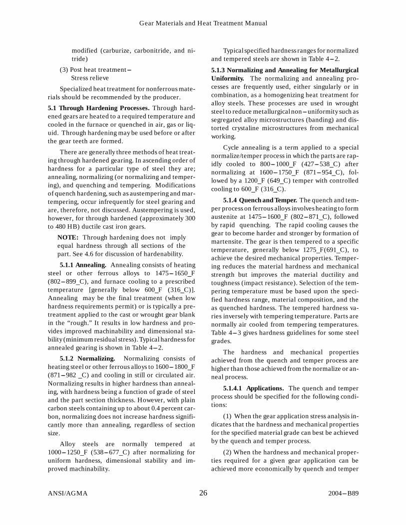
Gear Materials and Heat Treatment Manual
2004---B8926ANSI/AGMA
modified (carburize, carbonitride, and ni-tride)
(3) Post heat treatment---Stress relieve
Specialized heat treatment for nonferrous mate-rials should be recommended by the producer.
5.1 Through Hardening Processes. Through hard-ened gears are heated to a required temperature andcooled in the furnace or quenched in air, gas or liq-uid. Through hardening may be used before or afterthe gear teeth are formed.
There are generally three methods of heat treat-ing through hardened gearing. In ascending order ofhardness for a particular type of steel they are;annealing, normalizing (or normalizing and temper-ing), and quenching and tempering. Modificationsof quench hardening, such as austempering and mar-tempering, occur infrequently for steel gearing andare, therefore, not discussed. Austempering is used,however, for through hardened (approximately 300to 480 HB) ductile cast iron gears.
NOTE: Through hardening does not implyequal hardness through all sections of thepart. See 4.6 for discussion of hardenability.
5.1.1 Annealing. Annealing consists of heatingsteel or other ferrous alloys to 1475---1650_F(802---899_C), and furnace cooling to a prescribedtemperature [generally below 600_F (316_C)].Annealing may be the final treatment (when lowhardness requirements permit) or is typically a pre-treatment applied to the cast or wrought gear blankin the “rough.” It results in low hardness and pro-vides improved machinability and dimensional sta-bility (minimumresidual stress). Typical hardness forannealed gearing is shown in Table 4---2.
5.1.2 Normalizing. Normalizing consists ofheating steel or other ferrous alloys to 1600---1800_F(871---982 _C) and cooling in still or circulated air.Normalizing results in higher hardness than anneal-ing, with hardness being a function of grade of steeland the part section thickness. However, with plaincarbon steels containing up to about 0.4 percent car-bon, normalizing does not increase hardness signifi-cantly more than annealing, regardless of sectionsize.
Alloy steels are normally tempered at1000---1250_F (538---677_C) after normalizing foruniform hardness, dimensional stability and im-proved machinability.
Typical specified hardness ranges for normalizedand tempered steels are shown in Table 4---2.
5.1.3 Normalizing and Annealing for MetallurgicalUniformity. The normalizing and annealing pro-cesses are frequently used, either singularly or incombination, as a homogenizing heat treatment foralloy steels. These processes are used in wroughtsteel to reduce metallurgicalnon---uniformity such assegregated alloy microstructures (banding) and dis-torted crystaline microstructures from mechanicalworking.
Cycle annealing is a term applied to a specialnormalize/temper process in which the parts are rap-idly cooled to 800---1000_F (427---538_C) afternormalizing at 1600---1750_F (871---954_C), fol-lowed by a 1200_F (649_C) temper with controlledcooling to 600_F (316_C).
5.1.4 Quench and Temper. The quench and tem-per process on ferrous alloys involves heating to formaustenite at 1475---1600_F (802---871_C), followedby rapid quenching. The rapid cooling causes thegear to become harder and stronger by formation ofmartensite. The gear is then tempered to a specifictemperature, generally below 1275_F(691_C), toachieve the desired mechanical properties. Temper-ing reduces the material hardness and mechanicalstrength but improves the material ductility andtoughness (impact resistance). Selection of the tem-pering temperature must be based upon the speci-fied hardness range, material composition, and theas quenched hardness. The tempered hardness va-ries inversely with tempering temperature. Parts arenormally air cooled from tempering temperatures.Table 4---3 gives hardness guidelines for some steelgrades.
The hardness and mechanical propertiesachieved from the quench and temper process arehigher than those achieved from the normalize or an-neal process.
5.1.4.1 Applications. The quench and temperprocess should be specified for the following condi-tions:
(1) When the gear application stress analysis in-dicates that the hardness and mechanical propertiesfor the specified material grade can best be achievedby the quench and temper process.
(2) When the hardness and mechanical proper-ties required for a given gear application can beachieved more economically by quench and temper

Gear Materials and Heat Treatment Manual
2004---B8927ANSI/AGMA
of a lower alloy steel, than by normalizing or anneal-ing.
(3) When it is necessary to develop mechanicalproperties (core properties) in sections of the partwhich will not be altered by subsequent heat treat-ments (for example nitriding, flame hardening, in-duction hardening, electron beam hardening, and la-ser hardening).
5.1.4.2 Processing Considerations. The majorfactors of the quench and temper process that influ-ence hardness and material strength are:
(1) Material chemistry and hardenability(2) Quench severity(3) Section size(4) Time at temperature
The steel carbon content determines the maxi-mum surface hardness which can be achieved, whilethe alloy composition determines the hardness gra-dient which can be achieved through the part. Referto 4.6 for more information on hardenability.
5.1.4.3 Tempering. Tempering lowers hardnessand strength, which improves ductility and toughnessor impact resistance. The tempering temperaturemust be carefully selected based upon the specifiedhardness range, the quenched hardness of the part,and the material. The optimum tempering tempera-ture is the highest temperature possible while main-taining the specified hardness range. Hardness aftertempering varies inversely with the tempering tem-perature used. Parts are normally air cooled fromthetempering temperature.
Tables in the appropriate reference are availableas guidelines for the effect of tempering temperatureon hardness.
CAUTION: Some steels can become brittleand unsuitable for service if tempered in thetemperature range of 800---1200_F(425---650_C). This phenomenon is called“temper brittleness” and is generally consid-ered to be caused by segregation of alloyingelements or precipitation of compounds atferrite and prior austenite grain boundaries.If the part under consideration must be tem-pered in this range, investigate the specificmaterial’s susceptibility to temper brittlenessand proceed accordingly. Molybdenum con-tent of 0.25---0.50 percent has been shown toeliminate temper brittleness in most steels.Temper brittleness should not be confused
with the tempering embrittlement phenome-non from tempering in a lower range(500---600_F) often referred to as “500_F orA---Embrittlement.”5.1.4.4 Designer Specification. The designer
should specify the following on the drawing.(1) Grade of steel(2) Quench and temper to a hardness range.
The hardness range should be a 4 HRC or 40 HBpoint range. The designer should not specify a tem-pering temperature range on the drawing. It is bestto specify a hardness range and allow the heat treaterto select the tempering temperature to obtain thespecified hardness. Specifying both tempering tem-peratures and hardness ranges on a drawing causesan impractical situation for the heat treater. Temper-ing below 900_F(482_C) should be approved by thepurchaser.
(3) Any testing required. For example, hardnesstests, or any non---destructive tests such as magneticparticle inspection or dye penetrant inspection, in-cluding the frequency of testing.
5.1.4.5 Specified Hardness. The specified hard-ness of through hardened gearing is generally mea-sured on the gear tooth end face and rim section. His-torically, this has been interpreted to mean that thespecified hardness must be met at this location. De-signers often interpret this to mean that minimumhardness is to be obtained at the roots of teeth forgear rating purposes. Since depth of hardening de-pends upon grade of steel (hardenability), control-ling section size (refer to Appendix B) and heat treatpractice, achieving specified hardness on these sur-faces may not necessarily insure hardness at the rootsof teeth. If gear root hardness is critical to a specificdesign criteria, the gear tooth root hardness shouldbe specified. However, care should be taken to avoidneedlessly increasing material costs by changing to ahigher hardenability steel where service life has beensuccessful.
5.1.4.6 Maximum Controlling Section Size. Themaximum controlling section size is based upon thehardenability of alloy steel for through hardenedgear blanks. Appendix B illustrates the controllingsection for various gear configurations whose teethare machined after heat treatment.
5.1.4.7 Additional Information. For more in-formation, consult the following:
The ASM Handbook, Volume 4, Heat Treating,8th or 9th edition.

Gear Materials and Heat Treatment Manual
2004---B8928ANSI/AGMA
Military specification MIL---H---6875 and Mil---STD---1684.
5.1.5 Stress Relief. Stress relief is a thermal cycleused to relieve residual stresses created by prior heattreatments, machining, cold working, welding, orother fabricating techniques. The ideal temperaturerange for full stress relieving is 1100---1275_F(593---691_C). Lower temperatures are sometimesused when 1100_F (593_C) temperatures would re-duce hardness below the specified minimum. Lowertemperatures with longer holding times are some-times used.
NOTE: Stress relief below 1100_F(593_C) re-duces the effectiveness. Stress relief below900_F(482_C) is not recommended.
5.1.6 Heavy Draft, Cold Drawn, Stress RelievedSteel Bars. Heavy draft, cold drawn, stress relievedbars may be used as an alternative to quench andtempered steel. However, fatigue properties of thissteel may not be equivalent to quench and temperedsteel with the same tensile properties. Size limita-tions and mechanical properties are listed in Table4---5. For further details see ASTM A---311.
5.2 Flame and Induction Hardening. Flame or in-duction hardeningof gearing involves heating of gearteeth to 1450---1600_F(788---871_C) followed byquench and tempering. An oxyfuel burner is used forflame hardening. An encircling coil or tooth by toothinductor is used for induction hardening. These pro-cesses develop a hard wear resistant case on the gearteeth. When only the surface is heated to the re-quired depth, only the surface is hardened duringquenching (see Figs 5---1 and 5---2). Material selec-tion and heat treat condition prior to flame or induc-tion hardening significantly affects the hardness anduniformity of properties which can be obtained.
5.2.1 Methods of Flame and Induction Harden-ing. Both of these methods of surface hardening canbe done by spin hardening, or by tooth to tooth hard-ening.
Spin hardening of gearing involves heating all ofthe teeth across the face simultaneously by spinning
the gear element within the heat source (flame or in-duction coil) which envelopes the entire face width.Gearing is removed from the heat source and im-mediately hardened by the quenchant. Shafting andgearing can also be progressively spin hardened byspinning the shaft or tooth section within the heatsource and following quench head. The heat sourceand quench head traverse axially along the length tobe hardened.
Gearing can also be tooth to tooth, progressivelyhardened by passing the flame or inductor and fol-lowing quench head between the roots of teeth. In-ductor or flame heads or burner may be designed ei-ther to pass in the root diameter between flanks ofadjacent teeth, to heat the root diameter and oppo-site flanks of adjacent teeth, or may fit or encompassthe top land to heat the top land and opposite flanksof each tooth.
Heat sources designed to pass between adjacentteeth followed by quenching are desirable from bothendurance or bending strength and wear consider-ations, because both the flanks of teeth and root di-ameter are hardened. Only the non---critical toplands of teeth are not hardened. An inductor orflame head which encompasses only top lands ofteeth and adjacent flanks followed by quenching pro-vide wear resistance to the flanks, but endurance orbending strength in the roots is not enhanced. Resid-ual tensile stress in the roots of teeth may also provedetrimental. It is, therefore, recommended that boththe designer and heat treater know what type ofhardening pattern is desired.
Gearing may also be tooth to tooth, progressive-ly hardened by passing the inductor between theroots of adjacent teeth, while the gear element is sub-merged in a synthetic quench (termed “DelapenaProcess”). This process, like other tooth to toothhardening techniques, is time consuming and is noteconomical for small, finer pitch gearing (finer than10 DP). Spin hardening is more economical forsmaller gears.

Gear Materials and Heat Treatment Manual
2004---B8929ANSI/AGMA
SPIN FLANK FLAME HARDENING
FLAME HEAD
FLAME HEAD
FROM THIS TO THIS
FLANK FLAME HARDENING
FLANK AND ROOT FLAME HARDENING
THE HARDENING PATTERNS SHOWN ARE NOT POSSIBLE FOR ALL SIZES AND DIAMETRALPITCHES OF GEARING, AND ARE DEPENDENT UPON THE CAPACITY OF THE EQUIPMENT.
FLAME HEAD
FLAME HEAD
FLAME HEAD FLAME HEAD
FLAME HEAD FLAME HEAD
FROM THIS TO THIS
FROM THIS TO THIS
FROM THIS TO THIS
Fig 5---1 Variation in Hardening Patterns Obtainable on Gear Teeth byFlame Hardening

Gear Materials and Heat Treatment Manual
2004---B8930ANSI/AGMA
SPIN HARDENING
FLANK HARDENING
FLANK AND ROOT HARDENING
INDUCTION COILOR FLAME HEAD
INDUCTION COILOR FLAME HEAD
INDUCTOR OR FLAME HEAD INDUCTOR OR FLAME HEAD
INDUCTOR OR FLAME HEAD
Fig 5---2 Variations in Hardening Patterns Obtainable on Gear Teeth byInduction Hardening

Gear Materials and Heat Treatment Manual
2004---B8931ANSI/AGMA
Three basic gases are used for flame heating,which include MAPP, acetylene and propane. Thesegases are each mixed with air in particular ratios andare burned under pressure to generate the flamewhich the burner directs on the work piece.
Simple torch type flame heads are also used tomanually harden teeth. Since there is no automaticcontrolof this process, high operator skill is required.
Induction hardening employs a wide variety ofinductors ranging from coiled copper tubing to formsmachined from solid copper combined with lami-nated materials to achieve the required induced elec-trical currents.
Coarser pitch teeth generally require inductorspowered by medium frequency motor generator setsor solid state units. Finer pitch gearing generally uti-lizes encircling coils with power provided by high fre-quency vacuum tube units.
Wide faced gearing is heated by scanning typeequipment while more limited areas can be heated bystationary inductors. Parts are rotated when encir-cling coils are used.
Induction heating depth and pattern are con-trolled by frequency, power density, shape of the in-ductor, workpiece geometry and workpiece area be-ing heated.
Contour or profile hardened tooth patterns for4---12 D.P. gearing can be obtained by dual frequencyspin coil induction heating using both low (audio)frequency (AF) of 1---15 kHz and higher (radio) fre-quency (RF) of approximately 350---500 kHz. Initial-ly low audio frequency is used to preheat the rootarea, followed by high radio frequency to develop theprofile heated pattern, followed by quenching.
Quenching after flame or induction heating canbe integral with the heat source by use of a separatefollowing spray, or separate by using an immersionquench tank. Oil, water or polymer solutions can beused, in addition to air, depending upon hardenabil-ity of the steel and hardening requirements.
5.2.2 Application. Flame and induction harden-ing have been used successfully on most gear types;e.g., spur, helical, bevel, herringbone, etc. Theseprocesses are used when gear teeth require high sur-face hardness, but size or configuration does not lenditself to carburizing and quenching the entire part.These processes may also be used when the maxi-mum contact and bending strength achieved by car-burizing is not required. These processes are also
used in place of more costly nitriding which cannoteconomically generate some of the deeper cases re-quired.
Contour induction is preferred over flame whenroot hardness and closer control of case depth is re-quired. Contour flame hardening of the flanks androots is not generally available. The general applica-tion of flame hardening is to the flanks only, exceptwhen spin flame hardening is applied. The spin flameprocess generally hardens below the roots, but hard-ens teeth through the entire cross section, reducingcore ductility of teeth and increasing distortion (seeFig 5---2).
If high root hardness is not required, flame hard-ening is more available and more economical than in-duction hardening for herringbone and spiral bevelgearing.
NOTE: AGMA quality level will be reducedapproximately one level (from the greencondition) after flame or induction hardeningunless subsequent finishing is performed.
5.2.3 Material. A wide variety of materials canbe flame or induction hardened, including (cast andwrought) carbon and alloy steels, martensitic stain-less steels, ductile, malleable and gray cast irons.Generally, steels with carbon content of approxi-mately 0.35---0.55 percent are suitable for flame orinduction hardening. Alloy steels of 0.5 percent car-bon or higher are susceptible to cracking. The higherthe alloy content with high carbon, the greater thetendency for cracking. Cast irons also have a hightendency for cracking.
Selection of the material condition of the gear-ing can affect the magnitude and repeatability offlame and induction hardening. Hot rolled materialexhibits more dimensional change and variation thanhot rolled, cold drawn material because of densifica-tion from cold working. A quench and tempered ma-terial condition or preheat treatment, however, pro-vides the best hardening response and most repeat-able distortion.
5.2.4 Prior HeatTreatment. For more consistentresults, it is recommended that coarser pitched gearsof leaner alloy steels receive a quench and temperpretreatment; for example, 4140 steel with teethcoarser than 3 DP.
In both carbon and alloy steels, normalized orannealed structures can be hardened. These struc-tures do, however, require longer heating cycles anda more severe quench which increase the chance of

Gear Materials and Heat Treatment Manual
2004---B8932ANSI/AGMA
cracking. The annealed structure is the least recep-tive to flame or induction hardening.
Successful induction hardening of either gray orductile cast iron is dependent on the amount of car-bon in the matrix. The combined carbon in pearlitewill readily dissolve at the austenitizing temperature.Pearlite microstructures are desirable. Pearlite pro-moting alloy additions such as copper, tin, nickel ormolybdenum may be necessary to form this micro-structure.
5.2.5 Hardening Patterns. There are two basicmethods of flame or induction hardening gears, spinhardening and tooth to tooth hardening. See Figs5---1 and 5---2 for variations of these processes andthe resultant hardening patterns.
The hardening patterns shown are not possiblefor all sizes and diametral pitches. For coarserpitches, requirements should be worked out with thesupplier. For induction hardening, the kW or powercapacity of the equipment limits the pattern whichcan be attained. Root flame hardening by the toothby tooth process is difficult and should be specifiedwith care.
The induction coil method is generally limited togears of approximately 5 DP and finer. The maxi-mum diameter and face width of gears capable of be-ing single shot induction coil hardened is determinedby the area of the outside diameter and the kW ca-pacity of the equipment. Long slender parts can beinduction hardened with lower kW capacity equip-ment by having the coils scan the length of the partwhile the part is rotating in the coil.
Flank or root and flank induction scan harden-ing (contour) can be applied to almost any tooth sizewith appropriate supporting equipment and kW ca-pacity. However, for pitches of approximately 16 DPand finer, these methods are not recommended. Spinhardening in an induction coil is recommended. Spinhardeningof finer pitches is also required when usingflame burners.
The allowable durability and root strength ratingfor the different hardening patterns should be ob-tained from appropriate AGMA rating practices.These bending strength ratings are lower at the rootsof teeth when only the tooth flanks are hardened.
5.2.6 Process Considerations. Several areasmust be considered when processing. Some of themore critical requirements are outlined below.
5.2.6.1 Repeatability. Repeatable process con-trol is essential for acceptable results. With induc-tion, this is usually not a problemwith properly main-tained equipment since electrical power characteris-tics, inductor movement and integral quench intensi-ty can be readily controlled.
Repeatabiltiy becomes more difficult with flamehardening. Equipment varies from hand heldtorches to tailor made machine tools with well con-trolled movement of burner heads. Equipment mustbe such that heating rates across the burner face areconsistent from cycle to cycle. Gas pressure and mix-ing of heating gases must be uniform. Burner headlocation must be precise from cycle to cycle.
5.2.6.2 Heating with Flame or Induction. Accu-rate heating to the proper surface temperature is acritical step. Burner or inductor design, heat inputand cycle time must be closely controlled. Under-heating results in less than specified hardness andcase depth. Overheating can result in cracking.Flame hardening may also cause burning or meltingof tooth surfaces.
5.2.6.3 Quenching. Heat must be removedquickly and uniformly to obtain desired hardness.The quenchant should produce acceptable asquenched hardness, yet minimize cracking. Quen-chants used are: water, soluble oil, polymer, oil andair.
Parts heated in an induction coil are usuallyquenched in an integral quench ring or in an agitatedquench media. When the part is scanned while rotat-ing in a coil, a spray quench usually follows behindthe coil.
Flank hardened teeth usually have an integralquench following the inductor, or the gear is sub-merged in liquid during heating.
Quench time and temperature are critical andin---spray quenching, pressure velocity and directionof the quench media must be considered. Whenlocalized or air quenching is used, a coolant is usedon a portion of the metal away from the heating zoneto maintain the base metal near ambient tempera-ture so the part mass can absorb heat from the heatedzone.

Gear Materials and Heat Treatment Manual
2004---B8933ANSI/AGMA
5.2.6.4 Tempering. Tempering is mandatory onlywhen specified. However, for particular processes,judgment should be exercised before omitting tem-pering. It is good practice to temper after quenchingto increase toughness and reduce residual stress andcrack susceptibility. Tempering should be for a suffi-cient time to insure that hardened teeth reach thespecified tempering temperature. Flame hardenedparts which are air quenched are self tempered, andseparate tempering is unnecessary.
5.2.6.5 Surface Hardness. Surface hardness isthe hardness measured on the immediate surfaceand is primarily a function of the carbon content (seeFig 5---3). Hardness may be lower as a result of priorheat treatment, alloy content, depth of hardening,heating time, mass and quenching considerations.
5.2.6.6 Effective Case Depth. Effective casedepth for flame and induction hardened gears is nor-mally defined as the distance below the surface at the0.5 tooth height where hardness drops 10 HRCpoints below the surface hardness (see Fig 5---3).When a tooth is through hardened, effective case
depth does not apply. When root is also to be hard-ened, depth of case at the root may be specified.
5.2.7 Rating Considerations. Designers should beaware that AGMA decreases load ratings for gearswhich do not have hardened roots. AGMA gear rat-ing standards should be consulted for appropriatestress numbers.
5.2.7.1 Heat Affected Zone. In flame hardening, theheat affected zone (HAZ) is a region that is heated to1300---1400_F, (704_C---760_C) but does not gethardened and thus has lower strength. This zoneshould be located either a minimumof 1/8 inch up theflank from the critical root fillet or well below theroot diameter.
Contour induction hardening results in casedepth at the root to be approximately 60 percent ofthe depth at the pitchline due to mass quench andhardenabiltiy effect. Profile hardening of finepitched gearing using a submerged quench decreasesthe difference between pitchline and root casedepth.
CARBON CONTENT --- PERCENT0.20 0.30 0.40 0.50 0.60 0.70
40
30
50
60MAXIMUM SURFACE HARDNESS
EFFECTIVE CASE DEPTH HARDNESS
0.80
∆ = 10H
Fig 5---3 Recommended Maximum Surface Hardness and Effective Case DepthHardness Versus Percent Carbon for Flame and Induction Hardening

Gear Materials and Heat Treatment Manual
2004---B8934ANSI/AGMA
5.2.7.2 Case Depth Evaluation (Hardness Pat-tern). Although it is not always practical, particularlyon larger gearing, the only positive way to check casedepth is by sectioning an actual part. For tooth bytooth hardening, a segment of a gear can be hard-ened and sectioned. Case depth should be deter-mined on a normal tooth section, using an appropri-ate superficial or micro---hardness tester. When agear cannot be sectioned, hardness pattern anddepth can be checked by polishing end faces of teethand nitric acid etching. Grit blasting is also occasion-ally used. Hardness can also be checked on end facesat flank and root areas.
NOTE: During tooth by tooth inductionhardening, power is lowered and travel issometimes increased as the inductor ap-proaches the end faces. This is to preventedge burning and cracking. In theseinstances, hardness may be lower at the ends,particularly at the root area. In this case, exis-tence of a hardness pattern can be demon-strated by acid etching, but actual depth can-not be accurately measured.
5.2.8 Specifications. The drawing, order, or writ-ten specification should include the following in-formation:
(1) Chemical analysis range of the material ordesignation.
(2) Prior heat treatment.(3) Hardening pattern required.(4) Minimum surface hardness required.
(Maximums may be specified for induction hard-ened parts).
(5) Those areas where the surface hardness is tobe measured and the frequency of inspection.
(6) Depth of hardening required and the loca-tion(s) at which the depth is to be obtained.
(7) Whether destructive tests are to be used fordetermining the depth of hardeningand the frequen-cy of such inspection.
(8) Tempering temperature, if required.(9) Magnetic particle inspection, if required.
5.2.9 Documentation. The heat treater shouldsubmit the following information:
(1) Surface hardness range obtained and thenumber of pieces inspected.
(2) Depth of hardening obtained at each loca-tion specified when destructive tests are required,and the number of pieces inspected.
(3) Results of magnetic particle inspection, ifrequired.
5.3 Carburizing. Gas carburizing consists of heatingand holding low carbon alloy steel (0.07---0.28 per-cent Carbon) at normally 1650---1800_F(899---982_C) in a controlled atmosphere whichcauses additional carbon to diffuse into the steel(typically 0.70---1.10 percent carbon at the surface).
Gear blanks to be carburized and hardened aregenerally preheated after the initial anneal by a sub-critical anneal at 1100_F---1250_F (590---675_C),normalize, normalize and temper or quench andtemper to specified hardness before carburize hard-ening. This is done for machinability, dimensionalstability and possible grain refinement consider-ations. An intermediate stress relief before final ma-chining before carburizing may be used to remove re-sidual stress from rough machining.
After carburizing for the appropriate time, gear-ing will usually be cooled to 1475---1550_F(802---843_C), held at temperature to stabilize whilemaintaining the carbon potential, and directquenched. Gearing may be atmosphere cooled aftercarburizing to below approximately 600_F (315_C)and then reheated in controlled atmosphere to1475---1550_F (802---843_C) and quenched. Afterquenching, gearing is usually tempered at300---375_F (149---191_C). Gearing may be subse-quently given a refrigeration treatment to transformretained austenite and retempered.
5.3.1 Applications. Carburized and hardenedgearing is used when optimum properties are re-quired. High surface hardness, high case strength, fa-vorable compressive residual stress in the hardenedcase, and suitable core properties based on selectionof the appropriate carburizing grade of steel, resultin the highest AGMA gear tooth ratings for contactstress, pitting resistance and root strength (bending).Carburized gear ratings are higher than the ratingsfor through hardened and other types of surfacehardened gearing because of higher fatigue strength.Improved load distribution can be obtained by subse-quent hard gear finishing. Conventional hard gearfinishing (skiving and grinding) results in some sacri-fice of beneficial compressive stress at the surfaceand substantially increases costs.
Carburized gearing is used in enclosed gear unitsfor general industrial use, high speed and aerospaceprecision gear units and also large open gearing formill applications. Carburized gearing is also used for

Gear Materials and Heat Treatment Manual
2004---B8935ANSI/AGMA
improved wear resistance. Specified finish opera-tions after hardeningdepend upon accuracy and con-tact requirements for all applications.
Carburizing technology is well established andthe available equipment and controls make it a reli-able process. Surface hardness, case depth, and corehardness can be specified to reasonably close toler-ances, and the quality can be audited.
Some gearing does not lend itself to carburizehardening because of distortion. Gearing which dis-torts and cannot be straightened without cracking,rack gears, thin sections, complex shapes, parts notdesigned for finishing or where finishing is cost pro-hibitive, present manufacturing problems. Pressquenching after carburizing can be used to minimizedistortion. Selected areas of gearing can be pro-tected from carburizing (masked) to permit machin-ing after hardening, or can be machined after carbu-rizing and slow cooling before hardening.
Gearing beyond 80 inch (2032 mm) diameter isdifficult to carburize due to the limited number ofavailable furnaces for processing. Maximum size ofcarburize gearing is currently in the 120 inch (3048mm) diameter range. Most of this large gearing re-quires tooth finishing (skiving and/or grinding) aftercarburizing and hardening.
5.3.2 Materials. Material selection is an integralpart of the design process. Selection should be madeon the basis of material hardness and hardenability,chemistry, cleanliness, performance, and economicalconsiderations. Performance criteria include, but arenot limited to, the following: toughness, notch sensi-tivity, fatigue strength, bending strength, pittingwear resistance, and operational characteristics.Reference should be made to Table 4---1 for a list oftypical carburizing materials and Appendix C forcase hardenability considerations.
5.3.3 Control With Test Bars. Test bars are usedto show that the case properties and, when required,core properties meet specifications. Test bars shouldbe of the same steel type as the gear(s), but not neces-sarily the same heat. Bars should accompany gearingthrough all heat treatments, including all post hard-ening treatments. Consideration should be given toevaluation of that portion of the case that is not re-moved during tooth finishing.
A section, with a ground and polished surface(normal, at mid length of a test bar), is consideredsatisfactory for determining effective case depth of
carburized helical and spur gearing to 4 1/2 DP. Thetest bar should have minimum dimensions of 5/8 inch(16 mm) diameter by 2 inch (50 mm) long. One inch(25 mm) diameter ¢ 2.0 inch (50 mm) long bar maybe used for coarser pitch carburized gearing to 1.5DP. The size of the bar for coarser than 1.5 DP gear-ing should be mutually agreed upon, and shouldapproximate the inscribed diameter at mid height ofthe tooth cross section. The bar length should be2---3 times the diameter.
When specified, core hardness and core micro-structure can be determined at the center of theround bar size shown in Table 5---1 according to di-ametral pitch.
Table 5---1Test Bar Size for Core Hardness
Determination
BAR SIZEDP
4 1/2 DPand finer D. ¢ 3.0 inch
2 1/2 DPto less than
4 1/2 DPD. ¢
1 1/2 DPto less than
2 1/2 DPD. ¢
1 1/2 DPand coarser D. ¢
1.25 inch (32.0 mm)
(76 mm) long
2.25 inch (57 mm)5.0 inch
(130 mm) long
3.0 inch (76 mm)7.0 inch
(180 mm) long
3.5 inch (89 mm)8.0 inch
(205 mm) long
Test discs or plates may also be used whose mini-mum thickness is 70 percent of the appropriate testbar diameter. The minimum inscribed diameter on atest disc (or plate dimensions) should be a minimumof three times its thickness.
The recommended test bar diameter for bevelgearing is to be approximately equal to the inscribeddiameter of the normal tooth thickness at mid facewidth.
When disagreement exists as to the propertiesobtained on the test bar and the parts, an actual partmay be sectioned for analysis.
5.3.3.1 Case Hardness. Case hardness should bemeasured with microhardness testers which producesmall shallow impressions, in order that the hardnessvalues obtained are representative of the surfaces orarea being tested. Those testers which produce Dia-mond Pyramid or Knoop hardness numbers (500gram load) are recommended. When measuring di-

Gear Materials and Heat Treatment Manual
2004---B8936ANSI/AGMA
rectly on the surface of a case hardened part or testbar, superficial or standard Rockwell A or C scalemay be used. Other instruments such as Scleroscopeor Equotip are also used when penetration hardnesstesters can not be used. Consideration must be givento the case depth relative to the depth of the impres-sion made by the tester.
Low readings can be obtained when the indentorpenetrates entirely or partially through the case.
Microhardness tests for surface hardness shouldbe made on a mounted and polished cross---section ata depth of 0.002 to 0.004 inch (.05 to .10 mm) belowthe surface. Care must be taken during grinding andpolishing not to round the edge being inspected andnot to temper or burn the ground surface.
NOTE: Direct surface hardness readings(ASTM E18---79) or file checks at the toothtip or flank will generally confirm the casehardness. However, if secondary transforma-tion products are present below the first sev-eral thousandths of the case, direct surfacechecks will not necessarily indicate their pres-ence. Microhardness inspection 0.002 to 0.004inch (.05 to .10 mm) from the edge on a pol-ished cross section of the tooth is more accu-rate. This type of inspection may be necessaryfor accurate micro---hardness readings nearthe surface.
5.3.3.2 Core Hardness. When required, corehardness may be determined by any hardness tester,giving consideration to the size of the specimen asdiscussed in 5.3.3.
NOTES: See definition of core hardness,Section 3.
Occasionally banding, which results fromthe steel melting practice, can cause varia-tions in core hardness during testingwith a mi-crohardness tester. These variations shouldnot fall below the minimum, when core hard-ness is specified.
5.3.3.3 Case Depth --- Effective. The proceduresused to prepare the cross sectioned specimen forcase hardness (refer to 5.3.3) should be used to pre-pare the specimen for case depth evaluation. The mi-crohardness traverse should be started 0.002 to 0.004inch (.05 to .10 mm) below the surface and extend toat least 0.01 inch (.25 mm) beyond the depth at which50 HRC is obtained. Usually an interval of 0.005 inch
(0.13 mm) is used. Care should also be exercised inestablishing the perpendicular to the mid tooth pointwhen starting the traverse. Effective case depth atroots are typically 50---70 percent of mid tooth heightcase depths, and tips may be 150 percent of mid toothheight case depths.
NOTE: See definition of case depth of carbu-rized components, Section 3.
When steels of high hardenability such as 4320,4327, 8627, 4820, 9310, and 3310 are used for finepitches, the high through hardening characteristicsof the steel may prevent obtaining a hardness lessthan 50 HRC across the tooth section. The casedepth should then be determined in the followingmanner: Measure the base material hardness at midtooth height at the mid face. For each one HRC pointabove 45 HRC, one HRC point should be added tothe 50 HRC effective case depth criterion (example,core hardness equals 47 HRC, effective case depthshould be measured at 52 HRC). Case depth in theseinstances may also be measured on a test bar, if barsize has been previously correlated to the gear toothsection (refer to 5.3.3).
NOTE: Through carburized fine pitch teethhave several disadvantages. Favorable com-pressive surface stresses are lowered. Exces-sive tooth distortion and a loss of core ductil-ity can also occur. Parts of this type should becarefully reviewed for case depth specifica-tions and for use of lower hardenability steelssuch as 4620 and 8620.
5.3.3.4 Case Carbon Content. Surface carboncontent may be determined from a round test bar bytaking turnings to a depth of 0.005 inch (0.13 mm).Spectrographic techniques have also been developedfor this purpose. Carbon gradient can also be deter-mined on the bar by machining chips at 0.002 to0.010 inch (0.05 to 0.25 mm) increments through thecase, depending on accuracy desired and depth ofcase. Grinding in steps through the case would beused with spectrographic techniques.
Test specimens should be carburized with theparts. Care should be exercised to maintain surfaceintegrity during cooling or in tempering for subse-quent machining. Bar should be straightened to with-in 0.0015 inch (0.038 mm) (TIR) before machining.
Test specimens must be clean and machined dry.Care must be taken to ensure that the turnings are

Gear Materials and Heat Treatment Manual
2004---B8937ANSI/AGMA
free of any extraneous carbonaceous materials priorto analysis.
5.3.3.5 Microstructure. The microstructure maybe determined on a central normal section of the testbar or tooth, preferably mounted, after being prop-erly polished and etched.
Microstructure will vary with the core hardnessas related to steel hardenability, section size andquench severity.
5.3.4 Specifications. To aid in obtaining theabove characteristics, the heat treater should be giv-en the following as a minimum:
(1) Material.(2) Case depth range (refer to Table 5---2).(3) Surface hardness range.
When additional characteristics are required,the following additional items may be specified inwhole or part:
(1) Core hardness. Approximate minimumtooth core hardness, which can be obtained fromsome typical carburizing grades of steel and good agi-tated oil quenching, are shown in Table 5---3.
(2) Core microstructure.(3) Case microstructure.(4) Surface carbon content.(5) Subzero treatment.(6) Areas to be free of carburizing by appropri-
ate masking by copper plating or use of commercialstop---off compounds.
5.3.5 Carburizing Process Control. Precisioncarburizing requires close control of many factors in-cluding:
(1) Temperature Control. Furnace equipmentwith temperature uniformity, close temperature con-trol, and accuracy of temperature recording and con-trol instruments. Controls should be checked andcalibrated at regular intervals.
(2) Atmosphere Control. Furnaces should be ca-pable of maintaining a carburizing atmosphere withcontrollable carbon potential. Instrumentation for
continuous atmosphere control is preferred, but oth-er approved methods may be used.
(3) Subzero Treatment (Retained AusteniteConversion Treatment). When the surface hardnessis low due to excessive retained austenite in the casemicrostructure, it may be necessary to refrigerate theparts to transform the retained austenite to marten-site. The refrigeration treatment may vary from20_F(---7_C) to ---120_F (---84_C). To minimize micro-cracking, parts should be tempered before and afterrefrigeration.
NOTE: Caution should be exercised in theuse of refrigeration treatment on criticalgearing. Microcracks can result which canreduce fatigue strength to a moderate de-gree. Use of refrigeration may requireagreement between the customer and sup-plier.
(4) Carbide Control. When high surface carbonresults in a heavy continuous carbide network in theouter portion of the case, parts should be reheated totypically 1650_F(900_C)in a lower carbon potentialatmosphere, typically 0.60 percent carbon, to diffuseand break up the excess carbide. Carbide networksshould be avoided whenever possible as they tend toreduce fatigue strength of the material.
(5) Decarburization. Surface decarburization asdefined for carburized gearing is a reduction in thesurface carbon in the outer 0.005 inch (.13 mm) be-low the specified minimum. This is characterized byan increase in carbon content with increasing depth;for example, when the peak carbon content is subsur-face.
Gross decarburization can be readily detectedmicroscopically as a lighter shade of martensite andclearly defined ferrite grains. Hardness in this areawill be substantially lower.
Partial decarburization will result in a lightershade of martensite, but may not show discernibleferrite. It will result in reduced hardness if the car-bon content falls below approximately 0.60 percent.

Gear Materials and Heat Treatment Manual
2004---B8938ANSI/AGMA
Table 5---2Typical Effective Case Depth Specifications for Carburized Gearing
3 4 5, ,Normal
DiametralPitch
NormalTooth
ThicknessSpur, Helical
Bevel & MitreWorms with
Threads
NormalDiametral
Pitch
NormalCircular
PitchGround
Effective Case Depth (inches) to RC 50Range ofRange of
7621
16 0.098 17.5 --- 13.7 0.180 --- 0.230 0.010 --- 0.020 0.020 --- 0.03014 0.112 17.5 --- 13.7 0.180 --- 2.300 0.010 --- 0.020 0.020 --- 0.03012 0.131 13.7 --- 10.5 0.230 --- 0.300 0.015 --- 0.025 0.025 --- 0.04010 0.157 10.5 --- 8.5 0.300 --- 0.370 0.020 --- 0.030 0.035 --- 0.0508 0.198 8.5 --- 7.5 0.370 --- 0.480 0.025 --- 0.040 0.040 --- 0.0557 0.224 7.5 --- 6.5 0.370 --- 0.480 0.025 --- 0.040 0.040 --- 0.0556 0.251 6.5 --- 5.2 0.480 --- 0.600 0.030 --- 0.050 0.045 --- 0.0605 0.314 5.2 --- 4.3 0.600 --- 0.728 0.040 --- 0.060 0.045 --- 0.0604 0.393 4.3 --- 3.7 0.728 --- 0.860 0.050 --- 0.070 0.045 --- 0.0603.5 0.449 3.7 --- 3.1 0.860 --- 1.028 0.060 --- 0.080 0.060 --- 0.0753.0 0.523 3.1 --- 2.8 1.026 --- 1.200 0.070 --- 0.090 0.075 --- 0.0902.75 0.571 2.8 --- 2.6 1.026 --- 1.200 0.070 --- 0.090 0.075 --- 0.0902.5 0.628 2.6 --- 2.3 1.200 --- 1.400 0.080 --- 0.105 0.075 --- 0.0902.25 0.698 2.3 --- 2.2 1.200 --- 1.400 0.080 --- 0.105 0.075 --- 0.0902.0 0.785 2.2 --- 1.9 1.428 --- 1.676 0.090 --- 0.125 0.075 --- 0.0901.75 0.897 1.9 --- 1.6 1.676 --- 1.976 0.105 --- 0.140 0.075 --- 0.0901.5 1.047 1.6 --- 1.3 1.976 --- 2.400 0.120 --- 0.155 0.075 --- 0.0901.25 1.256 1.3 --- 1.1 2.400 --- 2.828 0.145 --- 0.180 0.075 --- 0.0901.0 1.570 1.1 & less 2.828 & more 0.170 --- 0.205 0.075 --- 0.0900.75 2.094 1.1 & less 2.325 & more 0.170 --- 0.205 0.075 --- 0.090
1 All case depths are based on normal diametral pitch. All other pitch measurements should beconverted before specifying a case depth.
2 Gears with thin top lands may be subject to excessive case depth at the tips. Land width should becalculated before a case is specified.
3 Case at root is typically 50---70 percent of case at mid tooth.4 The case depth for bevel and mitre gears is calculated from the thickness of the tooth’s small end.5 For gearing requiring maximum performance, detailed studies must be made of the application,
loading and manufacturing procedures to determine the required effective case depth. For furtherdetails refer to AGMA 2001---B88.
6 To convert above data to metric, multiply values given by 25.4 to determine mm equivalent.7 Worm and ground---thread case depths allow for grinding. Un---ground worm gear cases may be
decreased accordingly. For very heavily loaded coarse pitch ground thread worms, heavier case depththan shown in table may be required.
5.4 Carbonitriding. The purpose of this Section is toestablish methods for specifying carbonitrided gear-ing. Information in 5.3 on carburizing will generallyapply to carbonitriding, with noted exceptions.
Typically carbonitriding is carried out at lowertemperatures, 1550---1650_F (843---899_C), and forshorter times than gas carburizing. Shallower casedepths are generally specified for carbonitridingthan is usual for production carburizing. Its effect onsteel is similar to liquid cyaniding and has replacedcyaniding because of cyanide disposal problems.
Normally 2.5 to 5 percent anhydrous ammonia isadded to the carburizing atmosphere when carboni-triding. Specified case depths are usually from 0.003to 0.030 inch (0.076 to 0.76 mm) maximum.
5.4.1 Applications (Advantages and Limita-tions). Use of carbonitriding is more restricted thancarburizing. It is limited to shallower cases for finerpitch gearing since the process must be conducted atlower temperatures than carburizing. Deep casedepths require prohibitive time cycles. One of the

Gear Materials and Heat Treatment Manual
2004---B8939ANSI/AGMA
advantages of carbonitriding is better case harden-ability in lower alloy or plain carbon steels. The car-bonitrided case has better wear and temper resis-tance than a straight carburized case. Carbonitridingcan be used to minimize distortion in finer pitchgearing because lower austenitizing and quenchingtemperatures can be used along with less severequench techniques and still achieve hardness. Thesefacts, along with lower alloy steels, result in the lowercore hardness mentioned previously, thus reducingtooth growth and distortion. However, if higher corehardness and deeper case depths are required forbending resistance, carbonitriding may not be appli-cable.
Table 5---3Approximate Minimum Core Hardness of
Carburized Gear Teeth
Pitch 2---3 4 5---6 7 & UP
Hardness HRC Minimum1
Grade
3316 34 36 37 389315 32 34 36 373310 31 33 35 369310 28 31 33 344820 27 33 35 368822 25 30 32 344320 23 27 30 338620 18 24 26 284620 --- 18 22 251020 --- 14 16 18
1 Depending upon the Jominy curve of theparticular material, maximum hardness willtypically be 8---10 points higher than theminimums listed. Use of H band steel is thenormal method of hardenability control.
5.4.2 Materials. Typically carbon and low alloysteels such as 1018, 1022, 1117, 4022, 4118 and 8620steels are used for carbonitriding.
5.4.3 Specification and Inspection. Case depth,microstructure, hardness, etc. for carbonitridedparts can all be specified and evaluated as prescribedin the section for carburized gearing. Case depth isspecified and measured as effective or total, depend-ing upon application. Cases shallower than 0.010inch (0.25 mm) are generally specified as total casedepth. The advantages and limitations as describedherein should be fully understood before specifyingcarbonitriding for industrial gearing.
5.5 Nitriding. The purpose of this section is toprovide information, means of specifying, and in-
spection of nitrided gearing. This section covers theselection and processing of materials, hardnesses ob-tainable, and definitions and inspection of depth ofhardening.
Conventional gas nitride hardening of gearing,which has had a quench and temper pretreatmentand is usually finish machined, involves heating andholding at a temperature between 950---1060_F(510---571_C) in a controlled cracked ammonia at-mosphere (10 to 30 percent dissociation). Nitridehardening can also be achieved with the ion nitridingprocess. During nitriding, nitrogen atoms are ab-sorbed into the surface to formhard iron and alloy ni-trides. The practical limit on case depth is about0.040 inch (1.0 mm) maximum, which requires a thor-ough stress analysis (for other than wear applica-tions) of the effectiveness of the case for coarse pitchgearing.
NOTE: The above processes (5.4 and 5.5)should not be confused with aerated saltbath nitriding or nitrocarburizing in whichnitrogen is absorbed into the steel surface atapproximately 1060_F(570_C) for shortcycles of 2.5 to 4.0 hours in an aerated saltbath or atmosphere. These processes resultin a wear resistant surface layer of 0.001 inch(0.025 mm) or less, with a nitrogen com-pound layer to a depth of 0.015---0.020 inch(0.38---0.50 mm) which enhances fatiguestrength.
5.5.1 Applications. Nitrided gears are usedwhen gear geometry and tolerances do not lendthemselves to other case hardening methods becauseof distortion, and when through hardened gears donot provide sufficient wear and pitting resistance.Nitrided gears are used on applications where thin,high hardness cases can withstand applied loads. Ni-trided gears should not be specified if shock loadingis present, due to inherent brittleness of the case.
5.5.2 Materials. Steels containing chromium,vanadium, aluminum, and molybdenum, either sin-gularly or in combination, are required in order toform stable nitrides at the nitriding temperature.
Typical steels suitable for nitriding are 4140,4150, 4340, the Nitralloy grades, and steels with chro-mium contents of 1.00 to 3.00 percent. Aluminumcontaining grades such as Nitralloy 135 and NitralloyN will develop higher case hardness.
5.5.3 Pre---treatments. Parts to be nitrided mustbe quenched and tempered to produce the essential-

Gear Materials and Heat Treatment Manual
2004---B8940ANSI/AGMA
ly tempered martensitic microstructure required forcase diffusion. Microstructure must be free of pri-mary ferrite, such as is produced by annealing andnormalizing, which produces a brittle case prone tospalling. The nitriding process will cause a slight uni-form increase in size. However, residual stressesfrom quench and tempering may be relieved at thenitriding temperature, causing distortion. Thisshould be avoided by tempering at approximately50_F (28_C) minimum above the intended nitridedtemperature after quenching. In order to minimizedistortion of certain gearing designs, intermediatestress relieving after rough machining at 25---50_F(14---28_C) below the tempering temperature mayalso be required prior to finish machining to relievemachining stresses before nitriding.
In alloys such as series 4140 and 4340 steels, ni-trided hardness is lessened appreciably by decreasedcore hardness prior to nitriding. This must be consid-ered when selecting tempering or stress relievingtemperatures.
If distortion control is very critical, the newer ionnitriding process should be considered. Nitridingcan be accomplished at lower temperatures with ionnitriding than those used for conventional gas nitrid-ing.
Nitridingover decarburized steel causes a brittlecase which may spall under load. Therefore, nitridedsurfaces subject to stress should be free of decarbu-rization.
Sharp corners or edges become brittle when ni-trided and should be removed to prevent possiblechipping during handling and service.
Where it is desired to selectively nitride a part,the surfaces to be protected from nitriding can beplated with dense copper 0.0007 inch (0.018 mm)minimum thickness, tin plate 0.0003 to 0.005 inch(0.008 to 0.13 mm) thick, or by coating with propri-etary paints specifically designed for this purpose.
Nitrided parts will distort in a consistent mannerwhen all manufacturing phases and the nitriding pro-cess are held constant. The amount and direction ofgrowth or movement should be determined for each
part by dimensional analyses both prior to and afternitriding.
5.5.4 Nitriding Process Procedures. Variables inthe nitriding process are the combined effects of sur-face condition, degree of ammonia dissociation,temperature, and time of nitriding. Nitrogen adsorp-tion in the steel surface is affected by oxide and sur-face contamination. In order to guarantee nitrogenadsorption it may be necessary to remove surface ox-idation by chemical or mechanical means.
The nitriding process affects the rate of nitrogenadsorption and the thickness of the resultant brittlewhite layer on the surface.
A two stage nitriding process (two temperatureswith increased percent of ammonia dissociation atthe second higher temperature) generally reducesthe thickness of the white layer to 0.0005---0.001 inch(0.013---0.026 mm) maximum. The white layer thick-ness is also dependent upon the analysis of steel.
The ion nitride process uses ionized nitrogen gasto effect nitrogen penetration of the surface by ionbombardment. The process can provide flexibility indetermining the type of compound produced. Theprocess can also be tailored to better control nitrid-ing of geometric problems, such as blind holes andsmall orifices.
5.5.5 Specific Characteristics of Nitrided Gear-ing. Nitriding does not lend itself to every gear ap-plication. The nitride process is restricted by and spe-cified by case depth, surface hardness, core hardnessand material selection constraints.
5.5.5.1 Material Selection. Selection of thegrade of steel is limited to those alloys that containmetal elements that form hard nitrides as discussedin 5.5.2.
5.5.5.2 Core Hardness. Core hardness obtainedin the quench and temper pretreatment must pro-vide sufficient strength to support the case underload and tooth bending and rim stresses. Core hard-ness requirements limit material selection to thosesteels that can be tempered to the core hardnessrange with a tempering temperature that is at least50_F (28_C) above the nitriding temperature.Approximate core hardness

Gear Materials and Heat Treatment Manual
2004---B8941ANSI/AGMA
obtained on typical nitrided steels are as follows:
Minimum SurfaceSteel Type Hardness, HRC
4140 284150 304340 32Nitralloy 135 34
5.5.5.3 Surface Hardness. Surface hardness islimited by the concentration of hard nitride formingelements in the alloy and the core hardness of thegear. Lower core hardness does not support the hard,thin case as well as higher core hardness. Lower corehardness will result from less alloy, larger sectionsize, reduced quench severity and a greater degree ofmartensite tempering. Lower core hardness resultsin a microstructure which causes a lower surfacehardness nitrided case, since it limits the ability toform high concentration of hard metallic nitrides.Surface hardness will also increase with increasingnitride case depth.
Approximate minimum surface hardness whichcan be obtained on nitrided steel is shown in Table5---4.
Table 5---4Approximate Minimum Surface Hardness
--- Nitrided Steels
Minimum SurfaceHardnessSteel Type
R15N HRC!
4140 85 484150 85 484340 84 46
Nitralloy (contains Al) 90 60
2 1/2 percent Chrome 89 58(EN 40B & 40C and31CrMoV9)@
1 Converted to HRC2 British and German analyses, respectivelyNOTE: Data infers a 269HB minimum core hard-ness.
5.5.5.4 Case Depth. The specified case depth fornitrided gearing is determined by the surface andsub---surface stress gradient of the design applica-tion. Surface hardness and core hardness will influ-ence the design’s minimum required case depth.Since the diffusion of nitrogen is extremely slow,
most specifications only specify a minimum casedepth requirement.
Case depth should be determined using a micro-hardness tester. At least three hardness tests shouldbe made beyond the depth at which core hardness isobtained to assure that the case depth has beenreached.
A test bar, for example 1/2 to 1 inch (13 to 25mm) diameter with a length 3 ¢ the diameter, discorplate section, can be used for determining case depthof nitrided parts. The test section must be of the samespecified chemical analysis range and must be pro-cessed in the same manner as the parts it represents.
Sectioning of an actual part to determine casedepth need only be performed when the results of thetest bar are cause for rejection, or the surface hard-ness of the part(s) is not within 3 HRC points of thesurface hardness of the test bar.
5.5.6 Specifications. Parts which are to be nitridedshould have the following specified:
(1) Material grade(2) Preheat treatment (see 5.5.5.2)(3) Minimum surface hardness(4) Minimum total case depth(5) Maximum thickness of white layer, if
required(6) Areas to be protected from nitriding by
masking, if required(7) Nitriding temperature(8) Metallurgical test coupons
5.6 Other Heat Treatments. Gearing may also beheat treated by other means, including laser heattreating and electron beam heat treating.
Both laser and electron beam surface hardeningof gears are selective in nature and are generally ap-plied to gears smaller than those routinely hardenedby other methods. The production quantity of anygear must be sufficient to justify the cost of capitalequipment and set---up to surface hardened by eitherprocess, such as quantity production for the automo-tive industry. These processes are not available fromcommercial heat treaters. Thermal energy for heat-ing the surface to the austenitizing temperature issupplied by either the laser (light amplification bystimulated emission of radiation) or electron (kinet-ic energy of electrons) beam, while the underlyingmass provides the heat sink to quench harden thesurface. Use of electron beam heat treating for gear

Gear Materials and Heat Treatment Manual
2004---B8942ANSI/AGMA
teeth is restricted, however, to full gear tooth con-tours, and is better suited for flat than curved sur-faces. This is true because the stream of electronsmust have line of sight access to the surface to behardened with a beam impingement angle of at least25 degree (25---90 degrees impingement anglerange). Dual laser beam optics have been developed,however, for flank and root contour surface harden-ing of gear teeth.
Reference should be made to the ASM MetalsHandbook, 9th Edition, Volume 4 on Heat Treatingfor additional information on laser and electronbeam heat treating, as well as other modifications ofheat treatments applied to gearing.
5.7 Quenching. Quenching is the rapid cooling ofsteel from a suitable elevated temperature. Thequenching process is one of the major operationsthat influences the microstructure, hardness, me-chanical properties and residual stress distribution,assuming the gear has been properly heated beforethe quench. The preferred microstructure afterquenching is primarily martensite.
The designer’s or heat treater’s responsibility isto select the quench variables to obtain the requiredproperties in the gear. The quench needs to be fastenough to avoid secondary transformation products,but slow enough to reduce distortion and avoidcracking. The material hardenability will determinehow severe the quench has to be for a particular partgeometry.
Quench cracks usually originate at sharp cornersor substantial section size changes. However, evenwith perfectly uniformsections, parts can easily crackif made of high---carbon, high---hardenability steelsand the quench is too severe. Delayed quench crackscan occur hours or days after quenching, especially ifimproperly tempered or stress relieved. It is goodpractice to immediately temper after quenching ifquench crack problems are a concern.
The main factors which control the quench rateare: part geometry, type of quenchant, degree ofagitation and quench temperature. The geometrywill affect how quickly and uniformly the quenchantwill circulate around the part. Pockets which trap va-
por bubbles and restrict the flowof quenchant shouldbe avoided.
There are a variety of quenchants to choose fromsuch as: oil, polymer, molten salt, water, brine andgases. Each variety is available with a wide range ofquench characteristics. Table 5---5 associates somematerial grades and their normally used quenchants.
Agitation is externally produced movement ofthe quenchant past the part. The degree and unifor-mity of agitation greatly influences its rate of heat re-moval. Agitation can be provided by propellers orpumps in the quench tank or by moving the partsthrough the quenchant.
The temperature of the quenchant may affect itsability to extract heat. Each quenchant should beused within its appropriate range of temperature.The temperature of a water quenchant is more criti-cal than that of an oil.
5.8 Distortion. Distortion of gearing during heattreatment is inevitable and varies with the hardeningprocess. The part design and manufacturing processmust consider movement during heat treatment. Tol-erancing must consider these changes. Section sizemodification may be required alongwith added stockfor grinding or machining after heat treatment.
5.8.1 Causes. Dimensional changes of gearingresulting from heat treatment occur principally whensteel is quenched. These changes occur in bothquenched and tempered and surface hardened gears.Distortion is due to mechanical and thermal stressesand phase transformation. Process variables and de-sign considerations have a significant effect upon theamount of distortion. High induced stress can resultin quench cracking. Thermal processes such asannealing, normalizing, and diffusion controlled sur-face hardening processes such as nitriding, which donot require liquid quenching, result in less distor-tions than processes that require liquid quenching.
5.8.2 Quenching and Tempering. Quenched andtempered gearing changes size and distorts due tomechanical and thermal stresses and microstructuraltransformations. Quenching the structure to marten-site prior to tempering results in steel growing in size.Tempering of the hardened structure reduces thevolume, but the combined effects of quenching andtempering still result in a volume and size increase.

Gear Materials and Heat Treatment Manual
2004---B8943ANSI/AGMA
Table 5---5Commonly Used Quenchants for Ferrous Gear Materials
Quenchant RemarksMaterial Grade
1020 Water or Brine Carburized and quenched with good quench agitation.
4118 Oil Carburized and quenched in well agitated conventional4620 oil at 80---160_F(27---71_C) is normally required. For8620 finer pitched gearing, hot oil at 275---375_F(135---190_C)8822 may be used to minimize distortion. Some loss in core4320 hardness will also result from hot oil quench.
3310 Oil Carburized and quenched in hot oil at 275---375_F(135---190_C). This is the preferred quench.
9310 In larger sections, conventional oil can be used.
1045 Water, Oil or Type of quenchant depends upon chemistry and section4130 Polymer size. Large sections normally require water or low8630 concentration polymer. Smaller sections can be
processed in well agitated oil.
1141 Oil or Polymer Good response in well agitated conventional oil or1541 polymer. Induction or flame hardened parts normally
quenched in polymer.
4140 Oil or Polymer Same as above; however, thin sections or sharp corners4142 can represent a crack hazard. Hot oil should be4145 considered in these cases. With proper equipment, air
quench can be used for flame hardened parts.
These are high hardenability steels which can be cracksensitive in moderate to thin sections. Hot oil is oftenused. High concentration polymer should be used withcaution.
4150 Oil or Polymer If conventional oil is used, parts are often removed warm4340 and tempered promptly after quench.43454350 Crack sensitivity applies also to flame or induction
hardened parts with high concentration polymer beingthe usual quenchant. Oil is sometimes used and airquench can be applied for flame hardening with properequipment.
Gray or Oil, Polymer Quench media depends upon alloy content. High alloyDuctile or Air irons can be air quenched to moderate hardness levels.Iron
Unalloyed or low alloy irons require oil or polymer.
In this section parts and flame or induction hardenedsurfaces can be crack sensitive.

Gear Materials and Heat Treatment Manual
2004---B8944ANSI/AGMA
Distortion of quenched and tempered gearingoccurs generally as follows:
(1) Gears(a) Outside and bore diameters grow larger
and go out of round.(b) Side faces become warped, and exhibit
runout.(2) Pinions. Pinions become bowed, with the
amount of bowing increasing with higher length/di-ameter ratios and smaller journal diameters; amountof bowing or radial runout is often confined to jour-nal diameters and shaft extensions for integral shaftpinions.
Normally, rough gear blanks (forging, barstock,or casting) have sufficient stock provided so distor-tion can be accommodated by machining. High L/Dratio pinions may require straightening and a ther-mal stress relief prior to finish machining. In someexceptional instances, straightening, thermal stressrelief, rough machining, and a second stress reliefprior to finish machining may all be necessary to keepthe pinion dimensionally stable during finish ma-chining. Sequence of manufacture is dependentupon design considerations and the temperatureused for stress relief. Stress relief temperature is de-pendent upon specified hardness and temper resis-tance of the steel.
Modified methods of quench hardening, such asaustempering of ductile iron, reduces distortion andforms a modified hardened structure at higher quen-chant temperatures than those conventionally used(refer to 4.8.4.3).
5.8.3 Surface Hardened Gearing. Distortionmust be minimized, controlled and made predictableto minimize costly stock removal (lapping, skiving, orgrinding), when tooth accuracy requirements dic-tate.
Selective surface hardening of gear teeth byflame and induction hardening results essentially inonly distortion of the teeth because only the teeth areheated and quenched. Amount of distortion in-creases with case pattern depth and increases asmore of the tooth cross section is hardened,compared to profile hardened tooth patterns. Dis-tortion is not limited to gear teeth, however, whenthe entire gear is heated and quenched as with carbu-rizing.
5.8.3.1 Carburized Gearing. Distortion of car-burized gearing makes it one of the least repeatableof surface hardened processes. Lack of repeatabilityis due to the greater number of variables which affectdistortion. Close control is, therefore, required. Dis-tortion results from microstructural transformation,and residual stress (from thermal shock, unevencooling, etc.) considerations. Transformation in thecase results in growth which sets up residual surfacecompressive stress. This stress is balanced by corre-sponding residual tensile stress beneath the case.
Principal variables affecting the amount ofgrowth, distortion, and residual stress include:
(1) Geometry.
(2) Hardenability (carbon and alloy content) ofthe base material. Higher hardenability increasesgrowth and distortion.
(3) Fixturing techniques in the furnace and dur-ing quenching.
(4) Carbon potential of the carburizing atmo-sphere.
(5) Carburizing temperature and temperatureprior to quenching.
(6) Time between quench and temper for richeralloys.
(7) Quenchant type, temperature and amountof agitation.
(8) Resultant metallurgical characteristics of thecase, such as carbon content, case depth, amount ofretained austenite, carbides, etc.
NOTE: Direct quenching generally results inless distortion than slow cooled, reheated andquenched gears, providing gears are properlycooled from the carburizing temperature tothe quench temperature before hardening.
Once a component is designed to minimize dis-tortion, processing techniques should be optimizedto make distortion consistent. At times, redesign ofcomponents may be required to reduce distortion.
Stock removal by grinding after carburize hard-ening should be limited to approximately 0.007 inch(0.18 mm) per tooth surface or 20 percent of the casedepth, whichever is less. Exception may be made forcoarser pitch gearing with cases 0.080 inches (2 mm)or greater. Surfaces other than the tooth flanks androots may tolerate greater stock removal.

Gear Materials and Heat Treatment Manual
2004---B8945ANSI/AGMA
General design considerations of carburizedgearing related to distortion include the following(refer to Fig 5---4):
(1) Larger teeth (lower DP) distort more.
(2) Rim thickness should be the same at both endfaces.
(3) Radial web support section under the rimshould be centrally located. Web support sectionthickness under the rim is recommended to be notless than 40---50 percent of the face width for preci-sion gears. Near solid “pancake” gear blanks, de-signed with moderate recess on both sides of the websection, distort less. The recess is provided to enableclean---up grinding of the rim and hub end faces afterhardening.
(4) Holes in the web section close to the rim, toreduce the weight or provide holes for lifting, maycause collapsing of the rim section over the holes.
(5) High length/diameter ratio pinions distortmore. Journals may be required to be masked in or-der to prevent carburizing and then be finish ma-chined after hardening with sufficient stock forclean---up. Masking can also be used for ease ofstraightening.
(6) Cantilever pinions, with teeth on the end ofthe shaft, and “blind ended” teeth on pinions, wherethe adjacent diameter is larger than the root diame-ter, present problems from both distortion and fin-ishing standpoints.
Distortion of carburized gearing also exhibits the fol-lowing typical characteristics (refer to Fig 5---5):
(1) Reduction in tooth helix angle (“helix un-wind”), which often requires an increased helix angleto be machined into the element prior to carburizing(more prevalent in pinions). Teeth on larger diame-ter, smaller face width gears may exhibit “helixwind---up” after hardening.
(2) End growth on gear teeth at both ends of theface due to increased case depth (carburizing fromtwo directions, 90 degrees apart, followed by im-proved quench action for the same reason) may ap-pear as reverse tooth crowning on narrow face gear-ing. Teeth are often crown cut prior to hardening tocompensate for reverse crown or are chamfered atthe ends of teeth. Teeth may also be both crown cutand chamfered.
(3) Eccentricity (radial run---out) of gears andtheir bores is dependent upon how they are fixturedin the furnace.
(4) Taper across the face (tapered teeth), boretaper and “hour---glassing” of the gear bore can oc-cur due to non---uniform growth of teeth across theface and non---uniform shrinking of the bores.
(5) Bowing of the integral shaft pinions. Inte-gral shaft pinions should, whenever possible, be hungor fixtured in the vertical position (axes vertical) tominimize bowing.
CANTILEVER PINION BLIND ENDED TEETH
CONCENTRIC BLANKS
HIGH L/D RATIO
Fig 5---4 General Design Guidelines for Blanks for Carburized Gearing

Gear Materials and Heat Treatment Manual
2004---B8946ANSI/AGMA
HOURGLASSING
BOWING
ECCENTRICITY
TAPER
STRAIGHT
END GROWTH(REVERSE CROWN)
HELICALUNWIND
Fig 5---5 Typical Distortion Characteristics of Carburized Gearing
Gears may be fixtured vertically through thebores or web holes on a support rod (axes horizon-tal), or fixtured horizontally (individually or stacked)to minimize distortion, depending on size and facewidth. Larger ring gears are positioned horizontallywith sufficient stock for clean---up of the teeth. Boresand web sections can be masked to prevent carburiz-ing, and enable subsequent machining.
Thin section gears, such as bevel ring gears, maybe press quenched to minimize distortion.
5.8.3.2 Flame and Induction Hardened Gearing.Flame and induction hardened gearing generally dis-tort less than carburized gearing because only theteeth are heated and subsequently quenched. Con-tour induction hardening of tooth profiles produceless distortion and growth than spin hardening meth-ods.
During both spin flame and spin induction hard-ening, the entire tooth cross section is often hard-ened to the specified depth below the roots of teeth.
For high bending strength applications, it is notdesirable to have the hardening pattern terminate inthe roots of the teeth because of residual tensilestress considerations. Distortion increases as agreater cross---section of a tooth is hardened. Spinflame and spin induction hardening generally pro-duce the following distortion characteristics:
(1) Helical unwinding of the gear teeth, as withcarburized pinions.
(2) Increased growth of the teeth (greater thanfor carburized gearing) because the entire toothcross section may be hardened in finer pitch gearing.
(3) Crowning or reverse crowning of the teethacross the face dependent upon the heat pattern.Crowning is more desirable from a tooth loadingstandpoint.
(4) Taper of teeth due to varied heat pattern andcase depth across the face.
Distortion of the teeth fromspin induction hard-ening is often considered more repeatable than withspin flame hardening, because of fewer human errorfactors involved during machine and inductor set---ups with induction hardening. Spin flame hardeninginvolves more manual set---up factors, which includepositioning of the flame, gas flows, etc. However,spin flame hardening can be engineered with specialflame heads and fixtures for required control.
CAUTION: Deep spin hardening of gearteeth may cause excessive tooth growth andmay affect bore size.5.8.3.3 Nitrided Gearing. Nitriding of gearing
results in less distortion, compared to carburize,flame, and induction hardening. Prior quench andtemper heat treatment, which results in distortion, isdone before machining and nitriding. Parts are alsonot heated above the transformation temperature orprevious tempering temperature of the steel duringnitriding, and are not quenched, as occurs duringcar-burizing, flame or induction hardening. Therefore,nitrided gear teeth are not generally required to be

Gear Materials and Heat Treatment Manual
2004---B8947ANSI/AGMA
ground or lapped after hardening to meet dimen-sional tolerance requirements. Bearing diameters ofshaft extensions are often ground after nitriding withonly minimum stock provided. Surfaces can also bemasked for subsequent machining.
When close tolerances are required, gearing canbe rough machined and stress relieved at50_F(28_C) below the prior tempering temperatureto relieve rough machining residual stress prior tofinish machining and nitriding.
During nitriding, outer surfaces grow approxi-mately 0.0005---0.001 inch (0.013---0.025 mm). Boressize may shrink up to 0.0015 inch (0.04 mm) depend-ing upon size.
5.9 Shot Peening. Shot peening is a cold workingprocess performed by bombarding the surface of apart with small spherical media which results in a thinlayer of high magnitude residual compressive stressat the surface. This stress may improve the bendingfatigue strength of a gear tooth as much as 25 per-cent. It is becoming an accepted practice to specifyshot peening on carburized and other heat treatedgears. Because the process increases bending fatiguestrength, it may be used either to salvage or upgradea gear design. Contact fatigue strength may also beimproved in some instances by shot peening, butquantitative data to substantiate this condition islimited. Shot peening should not be confused withgrit and shot blasting, which are cleaning operations.
5.9.1 Equipment. Machinery used for shotpeening should be automatic and provide means forpropelling shot by air pressure or centrifugal forceagainst the work. Mechanical means for moving thework through the shot stream by either translation orrotation, or both, should be provided. Machinerymust be capable of consistently reproducing the shotpeening intensity and coverage required.
Regardless of the type of equipment used, thegear must be rotated on its axis while exposed to theshot stream.
For optimization of shot peeningof gears, nozzletype equipment is generally preferred because of theability to vary the angle of shot impingement and,therefore, achieve more uniform intensity along thetoothform. This type of equipment is generally usedfor high performance gearing, although centrifugalwheel equipment is often used for very high volumeproduction.
5.9.2 Process Control. Because it is difficult todirectly measure the effects of shot peening on apart, a high degree of process control is essential toassure repeatability.
5.9.2.1 Intensity Control. Intensity refers to thekinetic energy with which the peening media strikesthe part. This energy controls the depth of the peen-ing effect. It is measured by shot peening a flat, hard-ened steel strip called an Almen Strip, in the samemanner as the part will be peened. The strip is heldflat on an Almen block placed in the representativelocation during the peening operation. When re-leased from the block, the strip will bow convexly onthe peened surface. The amount of bow is measuredin inches with a gauge and is called the arc height (seeFig 5---6). There are three classifications of AlmenStrips, N, A, and C, which have thicknesses of 0.031inch (0.8 mm), 0.051 inch (1.3 mm) and 0.0938inch(2.4 mm) respectively. Strips are SAE 1070 coldrolled spring steel, hardened and tempered to 40---50HRC. Flatness tolerance is +---0.0015 inch(+---0.04mm). Figure 5---6 also shows the dimensionsfor the Almen strips and holding fixture. An intensitydetermination must be made at the beginning, at in-tervals of no more than four hours and at the end ofeach production run.
Whenever a processing procedure is developedfor a new part, an intensity curve must be developedwhich establishes the time required to reach peeningsaturation of the Almen strip. This is accomplishedby shot peening several strips at various times of ex-posure to the shot stream and plotting the resultingarc heights. Saturation is defined as that point atwhich doubling the time of exposure will result in nomore than a 10 percent increase in arc height.
5.9.2.2 Shot Control. Shot size and shape mustbe carefully controlled during the shot peening pro-cess, to minimize the number of fragmented particlescaused by fracturing of the shot. These fragmentedparticles can cause surface damage. Also, as a resultof lower mass, fragmented shot particles will length-en the time to reach a specified peening intensity. Pe-riodic inspection of the shot is required to controlshot size and shape within specification limits. Whenthese limits are reached, the shot should be classifiedand separated to restore size and shape integrity asshown in MIL---S---13165B.
5.9.2.3 Coverage Control. Coverage refers tothe percentage of indentation that occurs on the sur-face of the part. One hundred percent coverage is de-

Gear Materials and Heat Treatment Manual
2004---B8948ANSI/AGMA
fined as uniform dimpling of the original part surfaceas determined by either visual examination using a10X magnifying glass or by using a fluorescent tracerdye in a scanning process. In the latter process, fullcoverage has been achieved when no traces of the dyeremain when viewed under ultraviolet light. A mini-mum of 100 percent coverage is required on any shotpeened part.
Coverage must be related to the part, not the Al-men strip. The actual part must be examined forcomplete coverage in all areas specified to be shotpeened. The peening time required to obtain 100percent coverage should be recorded. The time re-
quired to obtain multiples of 100 percent coverage isthat multiple times the time to reach 100 percent cov-erage (200 percent, 300 percent, etc.).
5.9.3 Design Consideration. The following sec-tions describe items that the designer should includein a shot peening specification.
5.9.3.1 Governing Process Specification. Acom-monly referenced shot peening specification isMIL---S---13165B which identifies materials, equip-ment requirements, procedures, and quality controlrequirements for effective shot peening. The SAEManual on Shot Peening, SAE---J808a---SAE HS84,may also be used.
3.0 0.015 in+---
0.031 0.001 in (0.79 0.02mm)+--- +---
+--- +---0.051 0.001 in (1.30 0.02mm)
+--- +---0.0938 0.001 in (2.38 0.02mm)
(76 0.4mm)+---
N STRIP
A STRIP
C STRIPPEENING NOZZLE
ARC HEIGHT
STRIP REMOVED, RESIDUALSTRESSES INDUCE ARCHING
HOLDINGFIXTURE
STRIP MOUNTED FORHEIGHT MEASUREMENT
(a) (b) (c)
0.75 in(19.0 mm)
10---32SCREWS
4 to 6 in(102 to 152 mm)
SHOT STREAM
ALMEN TEST STRIP
1.5 in(38.1mm) 0.75 in
(19.0 mm)
3.0 in(76 mm)
ALMEN STRIPS 0.745 to0.750 in(18.9 to19.0 mm)
PEENING TEST
HARDENEDBALL
SUPPORTS
MEASURING DIAL
3.0 in(76 mm)
Fig 5---6 Shot Peening Intensity Control5.9.3.2 Shot Size and Type. Shot type and size
selection depends upon the material, hardness, andgeometry of the part to be peened. Shot types avail-able are cast steel (S), conditioned cut wire (CW),glass bead, and ceramic. Most shot peening of fer-
rous materials is accomplished with cast steel shot.Cast steel shot is available in two hardness ranges:45---55 HRC, and 55---62 HRC. When peening gearshigher in hardness than 50 HRC, the harder shot
Gear Materials and Heat Treatment Manual
2004---B8949ANSI/AGMA
should be specified to achieve higher magnitudes ofcompressive stress (refer to Fig 5---7).
5.9.3.3 Intensity. The intensity governs thedepth of the compressive layer and must be specifiedas the arc height on the A, C, or N strip (see 5.9.2.1).The range of arc height is generally 0.004 inch (0.10mm) wide, but it can be specified to a closer tolerancefor more repeatable results. Figure 5---8 illustratesthe depth of the compressive layer on steel at 31 and52 HRC hardness according to intensity.
5.9.3.4 Coverage. In most cases, 100 percentcoverage is adequate. In some instances, it may bedesirable to specify multiples of 100 percent in an at-tempt to achieve more blending of a poorly machinedsurface. A typical statement in a blueprint specifica-tion is “100 percent minimum coverage.”
5.9.3.5 Masking. At times, it is desirable to maskfinished machined areas of the part from shot im-pingement. Typical masked areas would be finishedbores or bearing surfaces. If masking is required, thisshould be stated in the shot peening requirementsand defined on the drawing, with masked area toler-ances given.
5.9.3.6 Drawing Example. A typical example ofdrawing or blueprint specification for shot peeningwould be as follows:
Shot peen area(s) indicated with S170 cast steelshot to an intensity of 0.010---0.014A perMIL---S---13165B;
Mask area(s) indicated (if necessary). Otherareas optional.
Use 55---62 HRC shot, 100 percent minimumcoverage.
50
100
150
200
250
0 0.004 0.008 0.012 0.016
HRC 46 SHOT---
---
---
---
---
0 0
500
1000
1500
---
---
---
DEPTH IN INCHES
HRC 61 SHOT
Fig 5---7 Residual Stress by Peening 1045 Steel at 62 HRC with 330 Shot

Gear Materials and Heat Treatment Manual
2004---B8950ANSI/AGMA
0
.005
.010
.015
.020
.025
.030
.035
.040
0 .002 .004 .006 .008 .010C0
.25
.50
.75
1.0
0 .005 .010 .015 .020 .025INTENSITY
A
HRC 31
HRC 52
Fig 5---8 Depth of Compressive Stress Versus Almen Intensity for Steel
Table 5---6 gives shot size and intensity for vari-ous diametral pitches.
Table 5---6Typical Shot Size and Intensity for Shot
Peening
IntensityShot SizeDiametralPitch
8 --- 16 S110 0.006 --- 0.010A4 --- 7 S170 0.010 --- 0.014A2 1/2 --- 3 1/2 S230 0.014 --- 0.018A1 3/4 --- 2 S330 0.016 --- 0.020A3/4 --- 1 S550 0.006 --- 0.008C
NOTE: The values for shot size and intensityshould be considered typical and not manda-tory. Variables such as gear geometry, hard-ness, and surface condition in the root maymake other specifications more desirable.
5.9.3.7 General Comments. Additional com-ments for shot peening include the following:
(1) All magnetic particle or dye penetrant in-spections should be performed before shot peening.
The plastic flow of the surface as a result of peeningwill tend to obscure minute cracks.
(2) All heat treating operations must be per-formed prior to shot peening as high temperatures[over 450_F(232_C)] will thermally stress relieve thepeening effects.
(3) Generally all machining of areas to bepeened are complete prior to shot peening. It is pos-sible to restore surface finish in peened areas (andretain beneficial effects) by lapping, honing, or pol-ishing, if material removal is limited to 10 percent ofthe depth of compressive layer.
(4) Compressive residual stress levels producedby shot peening can be quantitatively measured byX---ray diffraction. Currently this must be measuredon a cut sample in a laboratory X---ray diffractionunit. Portable units are under development.
(5) When there are significant machining marksin the tooth roots, it is desirable to achieve an intensi-ty sufficient to produce a depth of compressive stressto negate the stress riser effect of the machiningmark. However, shot diameter should not exceed 50percent of the fillet radius.

Gear Materials and Heat Treatment Manual
2004---B8951ANSI/AGMA
5.10 Residual Stress Effects. Residual stresses playan important role in the manufacture and perfor-mance of gears. Residual stresses created by machin-ing and heat treating operations are responsible formuch of the distortion that occurs during manufac-ture. The residual stress distribution in finishedgears can determine whether or not the gears willsurvive in service. Residual stresses (either favorableor unfavorable) are induced mechanically, thermally,by phase transformation, or by modification of sur-face chemistry (such as by nitriding). Each of these,singularly and in combination (such as by carburiz-ing), can affect the degree of in---process distortionand the residual stress state present in the finishedparts. The following sections briefly discuss thecauses of each type of induced residual stress.
5.10.1 Mechanically Induced Residual Stresses.There are two types of mechanically induced residualstresses, machining stresses and finishing operationstresses. Machining stresses are created by the cut-ting of the gear shape and can be either beneficial ordetrimental. Parts given a final heat treatment afterfinish machining may have the gross residual stressesfrom milling, turning, and hobbing minimized by in-termediate stress relief heat treatments in order toprevent significant distortion during the final heattreatment. Machining cuts taken just prior to finalheat treatment must be light enough so as not tocreate significant residual stresses. Grinding after fi-nal heat treatment must be performed very carefullysince it can create residual tensile stresses in the sur-face of the gear which can adversely affect perfor-mance. Lapping, honing or careful grinding of gearsafter final heat treatment maintains beneficial com-pressive residual stresses. Finishing operations suchas shot peening (refer to 5.9) and roller burnishingalso impart beneficial compressive residual stresseswhen properly controlled. These operations are typi-cally performed on finished gears to improve the pit-ting and surface bending fatigue resistance.
Use of cubic boron nitride (CBN) grinding mayhave a favorable effect on the residual stresses in thefinished gear. Under extreme grinding conditions,however, CBN grindingmay also induce surface tem-pering residual tensile stresses. Other hard gear fin-ishing methods (e.g. skiving) will need to be individu-ally evaluated as to effect on residual stress levels.
5.10.2 Metallurgically Induced Residual Stress.The other types of residual stress, although quite dif-ferent, can all be categorized as being metallurgically
induced. Thermal, phase transformation and modifi-cation of surface chemistry stresses result from heattreatment of steel.
5.10.2.1 Thermal and Phase TransformationStresses. Thermal stresses result from the heatingand cooling of materials. Quenching, one type ofthermal stress, can also be considered a phase trans-formation stress. Quenching, particularly fastquenching to form martensite, generates both ther-mal and phase transformation stresses. For example,two types of residual stress patterns can form onquenching of a round bar. The most common type ofresidual stress pattern in small diameter bars is a ten-sile stress at the surface and a compressive stress atthe center. This stress pattern results from the sur-face of a bar cooling faster than the center. The phasetransformation to martensite creates volume expan-sion producing tensile stress at the surface. This inturn creates a compressive stress at the center.
The second and opposite type of residual stresspattern occurs during quenching of large diameterbars. In this situation, the surface hardens but thecenter remains at an elevated temperature for someextended period of time. The thermal contractionexceeds the expansion of the transformation to mar-tensite, setting up residual tensile stress at the centerand residual compressive stress at the surface.
These two types of stress patterns are deter-mined by two variables, size of the bar and speed ofthe quench. When the sum of these two variables islarge, for example large diameter bar with a fastquench, the stress pattern will be of the second typewith residual tensile stress at the center and residualcompressive stress at the surface. When the coolingrates of the surface and center are similar, the ther-mal contraction can not overcome the expansionfrom the martensitic formation and residual tensilestress will form at the surface, while the center willconsist of residual compressive stress.
5.10.2.2 Residual Stresses by Modification ofSurface Chemistry. This type of residual stress mustalso be considered in conjunction with thermal resid-ual stress because modification of surface chemistryrequires heating, and heating can introduce thermalstresses, which must be taken into account. Carbu-rizing, the most common type of surface chemistrymodification, will serve as a good example of thesetypes of residual stresses. In quenched carburizedsteels, the transformation temperature of austeniteto martensite in the core occurs at a much higher

Gear Materials and Heat Treatment Manual
2004---B8952ANSI/AGMA
temperature than the case, and as discussed in theprevious section, the austenite to martensite trans-formation creates a volume expansion. Therefore,as the part is cooling, transformation begins in thecore and moves outward toward the case setting uptensile stresses in the core. The expansion of the caseis opposed by the previously transformed core im-parting beneficial compressive stresses in the case.Compressive stresses in the case help reduce surfacepitting caused by tooth contact stress above and be-low the pitchline. They help counteract tensilestresses caused by bending in the root.
6. Metallurgical Quality Control
Metallurgical information should be availableregarding:
(1) incoming material grade information(2) incoming material hardness and
mechanical tests(3) heat treat process control(4) part characteristics(5) metallurgical testing (final product)(6) microstructure(7) test coupon considerations
Refer to Appendix D on Service Life Consider-ations.
6.1 Incoming Material Quality Control. Materialgrade is certified by chemical test. Generally this is adestructive process. The following types of tests arecommonly used and are listed in ascending order ofcost for ferrous materials:
(1) Spectrographic Analysis(2) X---Ray Analysis(3) Atomic Absorption(4) Wet Chemistry
Iron casting grades are identified by their me-chanical properties such as tensile strength, yieldstrength, and elongation. Hardness may be specifiedbut cannot be used to identify grade.
Bronze material grades are normally qualifiedusing chemical analysis and hardness tests.
Brass material grades are identified by chemicalanalysis.
NOTE: Source certification is commonly ac-cepted for analysis certification.
6.2 Incoming Material Hardness Tests. Materialhardness tests, often specified in accordance with
ASTM A370, are normally surface hardness testsmade using:
(1) Rockwell(2) Brinell(3) Rebound Tests (Equotip & Shore)
Hardness testing, using any method or instru-ment, must be made with calibrated instruments withdata substantiated and documented to insure reli-ability. Statistical process control (SPC) is an ac-cepted method of control.
Minimum number of hardness tests on both rimor edge faces of through hardened cast and forgedgear blanks is generally based on the outside diame-ter and increases with size. Hardness tests are madeon the rim edge at mid rim thickness after final heattreatment.
6.2.1 Cast Gears. Recommended number ofhardness tests are as follows:
Number of TestsRecommended
OutsideDiameter,
inches (mm) (Rim Face)
---_
04080
4080
120_
(1020)(1020 to 2030)(2030 to 3050)(3050)
248
16
OverOverOver 120
When two hardness tests are specified, one shallbe on the cope side, preferably over a riser; the otheron the drag side, approximately 180_ away.
When four hardness tests are specified, two testsshall be on the cope side, (one over a riser and theother approximately 180 degree away between ris-ers) and the other two tests shall be on the drag side90 degrees away from the tests on the cope side.
When eight hardness tests are specified, fourtests shall be on the cope side, (two over risersapproximately 180 degrees apart, two between risersalso approximately 180 degrees apart, 90 degreesaway from tests over the risers) and the other fourtests shall also be on the drag side, 90 degreesapart.
When sixteen hardness tests are specified, eighttests shall be on the cope side (four over risers andfour between risers around the gear), and the othereight tests shall be on the drag side equally spacedaround the gear. Large segmented gears shall behardness inspected on the cope and drag rim edge ofeach segment per agreement between the customerand supplier.

Gear Materials and Heat Treatment Manual
2004---B8953ANSI/AGMA
6.2.2 Forged Pinions and Gears. Forged pinionsand gears include cylindrical shapes, disc shapes andrings.
6.2.2.1 Cylindrical Shaped Forgings.
(1) A minimum of four hardness tests shall betaken on the major (tooth) diameter of forgings up tofifteen inches. Two readings, 180 degrees apart,shall be taken at the center of the length of the majordiameter (center of tooth section at mid face). Onereading shall be taken approximately 1 inch (25 mm)from each end of the major diameter, 180 degreesapart.
(2) A minimum of five hardness tests shall betaken on the major diameter of forgings over 15 in-ches (380 mm) in diameter. Three readings, 120 de-grees apart, shall be taken at the center of the lengthof the major diameter (center of the tooth section atmid face). One reading shall be taken approximately2 inches (50 mm) from each end of the major diame-ter, 180 degrees apart.
6.2.2.2 Disc Shape Forging.
(1) A minimum of two hardness tests, 180 de-grees apart with one on each side, shall be taken atthe mid radius on forgings of up to 18.0 inches (457mm) in diameter, inclusive.
(2)A minimum of four hardness tests, two oneach side 180 degrees apart, shall be taken at themid radius on forgings over 18.0 inches (457 mm) indiameter.
6.2.3 Forged Rings (Reference ASTM A290).Recommended number of hardness tests is as fol-lows:
Number of TestsDiameter of Ring,in (mm) Recommended
Up to 40 2 (180_ apart)(1016)
Over 40 to 80 4 (180_ apart)(1016 to 2032)
Over 80 to 120 6 (120_ apart)(2032 to 3048)
Over 120 8 (90_ apart)(3048)
(1) When a total of two hardness tests are speci-fied, they shall be made 180 degrees apart, one onthe ringedge and the other on the opposite ringedge.
(2) When a total of four hardness tests are speci-fied, they all shall be made 180 degrees apart on
each ring edge, 90 degrees apart from one edge tothe other.
(3) When a total of six hardness tests are speci-fied, they shall be 120 degrees apart on each rimedge.
(4) When a totalof eight hardness tests are speci-fied, they shall be made 90 degrees apart on eachrim edge.
6.3 Incoming Material Mechanical Tests. Mechani-cal property test bars, for tensile testing and less fre-quently impact testing, are only required when speci-fied. Refer to 6.8 for merits and limitations of me-chanical test bars.
Test bar stock for gearing manufactured fromforgings and bar stock are normally obtained from aprolongation or extension of the rough stock, in theaxial or longitudinal direction with respect to thecomponent and the direction of metal flow duringforging. Refer to ASTM A291 for mechanical testcertification of forged gearing.
Test bar stock, approximately 1.5 ¢ 5 ¢ 6.0 inch(38 ¢ 127 ¢ 152 mm) long, are normally attached tothe drag (bottom) rim edge of the casting or are castas separate test blocks from the same heat of steel.Refer to ASTM A148 for mechanical test certifica-tion of cast gearing.
Test bar stock should remain attached to or ac-company the rough stock until all thermal treatmentis completed.
Minimum tensile properties for steel gearing areshown in Tables 4---2, 4---3 and 4---7, and also inASTM A290, A291 and A148.
6.4 Heat Treat Process Control. The many variablesinvolved in the heat treatment of gear materialsmakes process control complex. Process variables in-clude: time, temperature, rate of heating and cool-ing, heating media, cooling media, types of controls,base material composition, condition of processequipment, evaluation techniques, and part geome-try.
Heat treat processes change the microstructureand mechanical properties of the gear material. Anydimensional change, such as distortion or partgrowth, and any cosmetic change, such as colorationor surface texture, are characteristics of a specificheat treat process, but are not primary factors forprocess control. Process parameters used to controlthe heat treatment of gear materials are as follows:

Gear Materials and Heat Treatment Manual
2004---B8954ANSI/AGMA
6.4.1 Temperature. Temperature selection andcontrol is an important parameter in the heat treat-ment of gear materials. In carburizing and nitriding,the rate of diffusion into steel is dependent on tem-perature. The carbon concentration in the furnaceatmosphere is also temperature dependent. Specifictemperature ranges are required to harden the vari-ous grades of steel. Hardness and mechanical prop-erties of a material grade are dependent on the tem-pering temperature after hardening.
6.4.1.1 Temperature Uniformity. Since theproperties obtained in gear materials are dependenton the temperatures at which they are treated, theuniformity of the temperature within the working di-mensions of the furnace equipment should be mea-sured. The amount of variation allowed is depen-dent on the type of heat treatment and the materialproperties desired.
6.4.1.2 Thermal History. It is advisable to makea time temperature plot of the heat treat processes asa monitoring device and as process documentation.This is usually accomplished with strip chart record-ers.
6.4.2 Time. The duration of each segment of theheat treat process is critical to achieving the desiredmaterial properties. For example, the depth of car-bon penetration during carburizing is dependent onhow long the part was held at the carburizing temper-ature.
When the furnace temperature instrument indi-cates that the furnace chamber has recovered itsheat, the part in the chamber may not be up to tem-perature. It is important that the part be held at tem-perature long enough for the entire part to be at tem-perature. Time at temperature for through harden-ing is generally 0.75 hour per inch (25.4 mm) of sec-tion.
6.4.3 Rate. The rates of heating and cooling areimportant considerations. For example, if an induc-tion hardened part is heated too slowly, the core ma-terial will get too hot and lose its mechanical proper-ties. If a steel gear is cooled too quickly, it will havehigh internal stresses and possibly crack.
6.4.4 Atmosphere Control. The composition ofthe furnace atmosphere is an important part of pro-cess control. Control of carbon potential in the fur-nace atmosphere is critical to carburizing and theprotection of surfaces from carbon pickup or deple-tion during the hardening process. There are three
commonly used methods for measuring and control-ling carbon potential in a furnace atmosphere:
(1) Water Vapor Concentration. For a giventemperature, the carbon concentration on the sur-face of the part is related to the water vapor con-centration (dew point) in a furnace atmosphere. Thewater vapor concentration is measured using a dewcell or dew pointer. The water vapor concentration isexpressed as the atmosphere dew point measured indegrees fahrenheit.
(2) Carbon Dioxide Concentration. The con-centrations of carbon dioxide and carbon monoxidein a furnace atmosphere at a given temperature arerelated to the carbon concentration on the surface ofthe part.
The carbon dioxide concentration is measuredwith an external infrared gas analyzer and expressedas a percentage.
(3) Oxygen Concentration. The concentration ofcarbon on the part surface is related to the oxygenconcentration in the furnace atmosphere at a giventemperature and carbon monoxide level. The oxy-gen concentration is measured with an oxygen probepositioned in the furnace heat chamber.
6.4.5 Quench Control. Control of the quenchingoperation involves monitoring the variables whichaffect the rate and uniformity of part cooling. This in-cludes inspecting the condition, cleanliness and con-centration (if applicable) of the quenchant; the prop-er operation of any device used for agitation; and en-suring that the quenchant stays at the proper temper-ature (refer to 5.7).
There are several methods available to monitorand quantify the cooling rate of the quenching pro-cess. These include the standard nickel ball test,magnetic test, hot wire test and interval test. Sampleparts or test coupons can also be used as long as thetest piece hardenability is accounted for (refer to 5.7on quenching).
6.4.6 Tempering Temperatures. It is importantthat the tempering temperature be controlled toachieve the desired hardness. It is prudent to selectan initial tempering temperature which is on the lowside of the tempering range. It is easier and morecost effective to retemper a part that is too hard, thanreharden and retemper a soft part.6.5 Part Characteristics.

Gear Materials and Heat Treatment Manual
2004---B8955ANSI/AGMA
Part characteristics such as hardness, micro---structure and test coupon results can provide valu-able information.
6.5.1 Hardness. Hardness is the most commoncharacteristic used to measure results of the heattreat process. There are numerous types of hardnesstesting devices which can be used, but each type hasits own application limits and must be used correctly.Statistical process control (SPC) is an acceptedmethod to insure reliability using hardness testing.
6.5.1.1 As Quenched Hardness. As quenchedhardness of a part is a good indicator of the heat treatprocess. Many factors determine the as quenchedhardness such as decarburization and retained auste-nite. High as quenched hardness is the result of goodheat treatment. Low as quenched hardness usuallyresults from one or more of many factors such as de-teriorating quenchant, malfunctioning quench agita-tors, or too low an austenitizing temperature.
6.5.1.2 Decarburization. If a surface has beendecarburized, hardness will be low. If the surfacehardness is low, it is advisable that two hardnesschecks be made on a qualifying test part to insurethat the hardness below the decarburized zone meetsblue print requirements. The two hardness checksshould be made using the following sequence: grindsurface for hardness measurement, regrind surfaceuntil the hardness indentation is removed, and thenmake another hardness measurement near the origi-nal location. If both measurements are the same,there is no decarburization. If the hardness in-creases, there is possible decarburization. To deter-mine the depth of decarburization, a test coupon orpart that was run with the load should be sectioned,mounted, polished and etched. It should be noted,however, that in most cases decarburization is notpermissible.
6.5.1.3 Post Temper Hardness Examination.Tempering parts reduces hardness. As temperingtemperature increases, hardness decreases. Temper-ing temperature is determined by many factors,mainly type of steel and as quenched hardness. Ahardness measurement technique can be used tomonitor furnace soak time and uniformity. If the parthardness is greater in a heavy section compared to alight section, or if the hardness increases as surfacemetal is removed, these are good indicators of insuf-ficient soak time. If the part hardness varies fromthespecified range between pieces in a furnace load, thisis a good indication of a processing problem.
6.5.1.4 Carburize and Harden Examination.Surface hardness and core hardness measurementsare used to monitor the carburizing process. If thecore hardness of a part is within the expected rangeregardless of the other hardness measurements, thepart was satisfactorily quenched. If the part hardnessis low, this is an indication of decarburization, inade-quate quenching, excessive retained austenite, un-dissolved carbides, too high tempering temperature,inadequate case depth, or low surface carbon.
6.5.1.5 Case Depth Examination. Carburizedcase depth is typically measured by making a micro-hardness traverse across a sectioned part or test cou-pon to find the depth from the surface where thehardness is equivalent to Rockwell C 50.
6.5.1.6 Retained Austenite Examination. If thesurface hardness of a carburized part is low, it may bedue to the presence of retained austenite in the car-burized case. Retained austenite can be transformedto martensite by freezing the carburized part. If thesurface hardness improves after freezing, there wasretained austenite in the carburized case which is anindicator of high surface carbon concentration or toohigh of a quench temperature.
6.5.2 Microstructure. The composition of thevarious phases in the microstructure of a gear will tella lot about the heat treat process. It is recommendedthat a trained metallographer or metallurgist per-form the microstructure analysis.
6.5.2.1 Tempered Martensite. If a hardened gearhas been correctly hardened and tempered, the mi-crostructure will be composed primarily of temperedmartensite provided that the hardenability of thesteel was adequate.
6.5.2.2 Bainite. If a gear has been improperlyquenched, the microstructure might be interspersedwith bainite, which is characterized by a feathery ap-pearance if severely under quenched, or a darkeracicular pattern for marginal quenching.
6.5.2.3 Retained Austenite. All carburized casemicrostructures will contain some retained auste-nite, usually less than 5 to 30 percent by volume.However, if the carbon content of the carburizedcase is high, a larger percentage of retained austenitewill be present and will reduce the case hardness. Re-tained austenite is characterized by a white back-ground in a matrix of other structures (see 6.5.1.6).
6.5.2.4 Undissolved Carbides. If a carburizedpart has an excessively high carbon concentration,

Gear Materials and Heat Treatment Manual
2004---B8956ANSI/AGMA
the microstructure will contain undissolved carbidesusually populating the case. Undissolved carbidesare characterized by blocky white regions in a matrixof martensite and retained austenite. A normalstructure will consist of light, scattered pinpoint car-bides, while a structure of excessively high carbonconcentration will have carbides contained in a net-work at the grain boundary. Continuous intergranu-lar carbide network is not desirable for gearing.
6.5.3 Test Coupons. Test coupons of representa-tive geometry are frequently used for destructivetesting in lieu of destroying gearing. Microstructureand hardness testing of test coupons can be corre-lated to gearing characteristics.
6.6 Metallurgical, Mechanical and Non---Destruc-tive Tests and Inspections. Tests and inspectionswhich may be made on the final or near final productare fatigue testing, hardness testing, surface temperinspection, magnetic particle inspection, and ultra-sonic inspection.
6.6.1 Fatigue Testing. Fatigue (life) testing ofthe final product is the proof of the suitability of thedesign for the intended purpose.
It is desirable to expedite this testing while main-taining validity of the test data. This can be done byrunning the test at some overload ratio and evaluat-ing the damage with time for the test conditions.Damage can be compared with that for the productdesign conditions. This comparison must be madefor both the beam strength and the surface durabilityof the teeth. Miner’s Rule is a widely accepted meth-od of making these comparisons.
When damage value accumulated on the testequals the damage value of the design, the test speci-men survived the minimum specified product life.
Due to the statistical nature of fatigue failurethere is a wide distribution of data. In low cycle fa-tigue where most high overload and damage frac-tures occur, this scatter band from the lower thresh-old to the upper threshold is approximately 100 to 1wide. Since the distribution may be considered a logfunction, it is necessary for about half the test units torun at ten times the threshold life to validate theproduct design. This would constitute a Miner’sRule damage of ten.
6.6.2 Hardness Testing on the Gear Product.Through hardened finish machine gearing can beconventionally hardness tested by standard and por-
table Brinell and Rockwell test machines providedthat the following are met:
(1) Surface to be inspected provides access andhas the required surface finish, generally 64 microin-ches (5 microns), or:
(2) If the size of the hardness impression on thetest surface is permitted, or:
(3) Mass of the test surface will support the testload.
Through hardened gearing is commonly in-spected on the faces of gear rims, top lands of teethwhere size permits, gap of herringbone (double heli-cal) gearing and on adjacent diameters of pinionsother than bearing journals. Through hardenedgearing is rarely inspected for hardness on the flanksof teeth or in root radii because hardenability of thesteel selected should insure obtaining the specifiedhardness at these locations. When hardness testersare not available for accurate measurement at rootsof teeth, destructive sectioningand testingmay be re-quired.
Other portable hardness testing instruments areavailable (ASTM A833). One tester uses a hammerto simultaneously impact a known hardness test barand the unknown workpiece with a hardened ball be-tween the two test surfaces. Comparison is made ofthe ball diameter on each to determine hardness ofthe unknown. Other portable instruments measurethe recoil or rebound height or velocity of a droppedhardened ball, or use a high ultrasonic frequency ac-tivated indenter to measure hardness.
It is desired that surface hardened gearing behardness inspected, non---destructively, so as not toleave an objectionable impression. Portable testerswhich measure the rebound height or velocity of adropped hardened ball or use a high ultrasonic fre-quency activated hardness indenter, may be used.
Conventional Rockwell test machines can beused to hardness inspect surface hardened gearingwhen size of the gearing permits and where a visibleimpression is permitted. Hardened files, includingthose tempered to lower hardness than 60---64 HRC,can also be used to approximate hardness by thescratch test (Reference SAE J---864). Inspection ofthe hardness on the flanks of surface hardenedcoarse gearing with non---destructive portable hard-ness testers can be improved when the instrumentcan be fixed for perpendicularity to the test surface.Hardness measurement in the roots of teeth may not

Gear Materials and Heat Treatment Manual
2004---B8957ANSI/AGMA
be reliable due to accessibility in the radius of curva-ture and surface roughness.
For improved accuracy and where permitted,through hardened steel and cast iron gearing shouldbe hardness inspected directly in Brinell (not con-verted). Hardness of surface hardened gearingshould be directly measured in Rockwell (C or Ascale) or converted to Rockwell with suitable porta-ble instruments.
Portable instruments vary in accuracy and reli-ability. Users, therefore, should take precautions toinsure accurate calibration and test results.
Hardness testing equipment manufacturersshould be contacted and literature searched for addi-tional information on principles of hardness inspec-tion, available test equipment and their capabilities.Statistical process control is a useful tool to be usedwith hardness testing.
6.6.3 Surface Temper Inspection. Surface tem-per inspection is used to detect and classify localizedoverheating on ground surfaces by use of a chemicaletch method. Details of the process are covered inAGMA 230.01, Surface Temper Inspection Process.
Inspection criteria includes a class designationfor critical and non---critical areas. To evaluate theseverity of surface temper, grinding burns are classi-fied by intensity of color from light gray to brown toblack. Severe burning or re---hardening is indicatedby patches of white in the darkened areas. Crackingmay also be present. Re---hardening or cracking arecause for rejection.
Tables I and II in AGMA 230.01 cover temperclasses ranging from Class A (Light temper) to ClassD (Heavy temper). Class C (Moderate temper) for alimited area and hardness reduction may be per-mitted.
Rework for excessive temper is generally per-mitted by mutual agreement between customer andsupplier.
Case depth shall be determined on a normaltooth section. Hardness testers which produce smallshallow impressions should be used in order that thehardness values obtained will be representative ofthe surface area being tested. Microhardness testerswhich produce Diamond Pyramid or Knoop Hard-ness number are recommended, although other tes-ters such as Rockwell superficial A or 15 N scales can
be used in some instances. Caution should be exer-cised if the heavier load C scale is used.
6.6.4 Magnetic Particle Inspection. Magneticparticle inspection is a non---destructive testingmethod for locating surface and near surface discon-tinuities in ferromagnetic material. When a magnet-ic field is introduced into the part, discontinuitieslaying approximately transverse to the magnetic fieldwill cause a leakage field. Finely divided ferromag-netic particles, dry or in an oil base or water base sus-pension, are applied over the surface of the materialunder test. These particles will gather and hold at theleakage field making the discontinuities visible to thenaked eye.
Use of electric current is, by far, the best meansfor magnetizing parts for magnetic particle inspec-tion. Either longitudinal or circular fields may beintroduced into parts. There are basically two typesof electric current in common use, and both are suit-able for magnetizing purposes in magnetic particletesting. The two types of current are direct currentand alternating current. The magnetic fields pro-duced by direct and by alternating currents differ inmany characteristics. The main difference, which isof prime importance in magnetic particle testing, isthat fields produced by direct current generally pene-trate the entire cross section of the part, whereas thefields produced by alternating current are confinedto the metal at or near the surface of the part undertest. From this, it is evident that when deep penetra-tion of field into the part is required, direct currentmust be used as the source of magnetizing force. Byfar, the most satisfactory source of D.C. is the rectifi-cation of alternating current. Both single phase andthree phase A.C. are furnished commercially. By theuse of rectifiers, reversing A.C. is rectified and thedelivered direct current is entirely the equivalent ofstraight D.C. for magnetic particle testing purposes.
Sources of alternating current are single phasestepped down to 115, 230, or 460 volts. This is accom-plished by means of transformers to the low voltagesrequired. At these low voltages, magnetizing cur-rents up to several thousand amperes are often used.The trend in Europe is to use A.C. current for mag-netic particle testing because the intent of their test-ing is location of surface discontinuities only. Subsur-face discontinuities are best detected by radiographyor ultrasonic non---destructive test methods. A.C.currents tends to give better particle mobility, and

Gear Materials and Heat Treatment Manual
2004---B8958ANSI/AGMA
demagnetization is more complete than with a D.C.field.
There are two essential components of magneticparticle testing, each of equal importance for reliableresults. The first is the proper magnetization of thepart to be tested, with proper field strength in the ap-propriate direction for the detection of defects. Thesecond is the use of the proper magnetic particlestype to secure the best possible defect indications un-der prevailing conditions.
6.6.4.1 General Principles. Some general prin-ciples and rules on magnetizing means, fieldstrength, current distribution and strength require-ments are listed below (refer to Figs 6---1 and 6---2).
(1) Fields should be at 90 degrees to the direc-tion of defects. This may require magnetizing in twodirections.
(2) Fields generated by electric currents are at 90degrees to the direction of current flow.
(3) When magnetizing with electric currents,pass the current in a direction parallel to the direc-tion of expected discontinuities.
(4) Circular magnetization has the advantageover longitudinal magnetization in that there arefew, if any, local poles to cause confusion in particlepatterns, and it is preferred when a choice of meth-ods is permissible.
(5) Circular magnetization specifications gener-ally require from 100 to 1000 amps per inch of partdiameter. Amperage requirements should be incor-porated into the magnetic particle procedure.
(6) For coil magnetization, a widely used formu-la for amperage calculations is:
NI = 45 000L/ D
(Eq 6.1)
whereNI = ampere turns required,L/D = length to diameter ratio.
NOTE: The 45 000 constant may vary withspecifications.
(7) For prod magnetization with direct current, aminimum of 60 amperes per inch of prod spacing willproduce a minimummagnetizing force of 20 oerstedsat the midpoint of the prod line for plate 3/4 inchthick or less. A safer figure to use, however, is 200amps per inch, unless this current strength producesan interfering surface power pattern. Prod spacingfor practical inspection purposes is limited to abouteight (8) inches maximum, except in special cases.
(8) All parts should be demagnetized after mag-netic particle inspection.
FIELD
BATH
CURRENT
DISCONTINUITY
HEAD SHOT
CIRCULAR MAGNETIZATION LOCATESDISCONTINUITIES OCCURRING 45 --- 90DEGREES TO THE DIRECTION OF THEFIELD.
INSPECT FOR PARTICLE INDICATIONSSHOWING LONGITUDINAL DISCONTINUITIES--- MARK DISCONTINUTIES.
HEAD
Fig 6---1 Circular (Head Shot) MagneticParticle Inspection
6.6.4.2 Magnetic Particles. The particles usedare finely divided ferromagnetic material. Propertiesvary over a wide range for different applications in-cluding magnetic properties, size, shape, density,mobility and visibility or contrast. Varying require-ments for varying conditions of test and varyingproperties of suitable materials have led to the devel-opment of a large number of different types of avail-able materials. The choice of which one to use is animportant one, since the appearance of the particle

Gear Materials and Heat Treatment Manual
2004---B8959ANSI/AGMA
patterns at discontinuities will be affected, even tothe point of whether or not a pattern is formed.
COIL SHOT IS A FEW INCHES ON EITHERSIDE OF COIL. MAXIMUM LENGTH OFARTICLE COVERED BY ONE SHOT IS18 INCHES (46 CM). ON LONG ARTICLES,REPEAT SHOTS AND BATHS DOWN THELENGTH OF ARTICLE. PLACE ARTICLESCLOSE TO THE COIL BODY.
EFFECTIVE LENGTH MAGNETIZED BYNOTE:
FIELD CURRENTTHROUGH
COIL
DISCONTINUITY
BATH
COIL SHOTLONGITUDINAL MAGNETIZATION LOCATESTRAVERSE DISCONTINUITIES.
INSPECT FOR PARTICLE INDICATIONSSHOWING TRANSVERSE DISCONTINUITIES.
Fig 6---2 Coil Shot Magnetic ParticleInspection
(1) Dry Powders. It is evident that size plays animportant part in the behavior of magnetic particles.A large, heavy particle is not likely to be arrested andheld by a weak field when such particles are movingover the surface of the part. On the other hand, veryfine powders will be held by very weak fields, sincetheir mass is very small. Extremely fine particles mayalso adhere to the surface where there are no discon-tinuities, especially if it is rough, and form confusingbackgrounds. Most dry ferromagnetic powders usedfor detecting discontinuities are careful mixtures ofparticles of all sizes. The smaller ones add sensitivityand mobility, while the larger ones not only aid in lo-cating large defects, but by a sweeping action, coun-teract the tendency of fine powders to leave a dustybackground. Thus, by including the entire size range,a balanced powder with sensitivity over most of therange of sizes of discontinuities is produced.
(2) Wet Method Materials. When the ferromag-netic particles are applied as a suspension in someliquid medium, much finer particles can be used. Theupper limit of particle size in most commercial wet
methods is in the range of 60 to 40 microns. Particleslarger than this tend to settle out of suspension rapid-ly. In general, wet method materials exhibit a greatersensitivity than dry powders. Fluorescent particleshave the greatest contrast of the wet method materi-als. Although fluorescent wet particles have thegreatest sensitivity and contrast, they can provide aconfusing background on surfaces with a finish great-er than 250 RMS.
6.6.4.3 Documented Procedures. Written proce-dures for magnetic particle testing should as a mini-mum include:
(1) Which ASTM, ASNT or agency specifica-tions the procedure meets.
(2) Qualifications---(a) Indicate that the operators are qualified
and tested to ASNT---TC---1A Level II, MIL---STD---271F, etc.
(b) Indicate type of equipment used for in-spection, A.C. and D.C. full wave rectified, etc.
(c) Indicate type of particles used for inspec-tion, fluorescent or black visible, wet or dry particle.For the wet method, particle concentration shouldalso be indicated.
(3) General---(a) State when inspection is to be done;after
heat treat, finish machining, etc.(b) State what the surface will be; for exam-
ple, 250 RMS, black forge, etc.
(c) State amps per inch of diameter for cir-cular magnetization and the formula used for cal-culation of longitudinal magnetization.
(d) State what method will be used for deter-mining field magitude; such as pie gage, etc.
(e) State demagnetization, if required, andlevel of demagnetization required.
(4) Standard of Acceptance(a) Indicate maximum size and density of
indications permitted.(b)Indicate reporting procedures ifneeded.
For further information on magnetic particletesting, refer to:
Principles of Magnetic Particle Testing, C.E. BetzMetals Handbook Volume II Eighth Edition
Nondestructive Inspection and Quality ControlNondestructive Testing Handbook, Edited by
Robert C. McMasters for the Society for Nonde-structive Testing

Gear Materials and Heat Treatment Manual
2004---B8960ANSI/AGMA
6.6.5 Ultrasonic Inspection. Ultrasonic inspec-tion is a nondestructive test method to determine theinternal soundness and cleanliness of gearing bypassing sound (ultrasound) through the material.Very short sound waves of a frequency greater than20,000 cycles per second (audible limit) are voltagegenerated and transmitted into the part by a trans-ducer. In the method most often used, returningsound waves are transformed into voltage and moni-tored on an oscilloscope screen.
There are two test methods used, dependingupon the media, for coupling the ultrasonic transduc-er to the heat treated work piece. Untreated coarsegrained structures do not lend themselves to ultra-sonic testing. Surfaces to be scanned, such as the out-side diameter and ends or end faces of cylindrical ordisc shaped rough stock are generally machined to125---250 micro--- inch maximum surface roughness.This provides improved contact for the transducerwith the work piece. One method uses a couplant:oil, glycerin or a commercial paste spread evenly onthe surfaces to be inspected. The second method useswater as the couplant, with the transducer and workpiece submerged in a tank.
With the most common technique of ultrasonicinspection, namely, the pulse echo technique, thetransducer both emits sound waves and receives thereturning signals from the back surface and possibledefects. The returning signals are subsequently mon-itored on an oscilloscope screen as shown in Fig 6---3.The indication to the left of the oscilloscope screen inFig 6---3 is caused by the sound wave entering thesteel and is called “initial pulse” or “contact interfer-ence.” The indication to the right is caused by soundreflecting off of the back surface and in the middle isthe signal reflecting from any defects shown. Thehorizontal line, called the “sweep line,” provides ameasure of distance or depth in the work piece, as re-lated to the rate of travel of sound in the material.The sweep line can be calibrated by use of a test blockor section of known thickness in the work piece in or-der that each marker shown on the sweep line repre-sents a standard distance or depth. Depth of the de-fect from the transducer contact point on the scan-ning surface can, therefore, be determined.
Before testing, the instrument must be cali-brated according to the test specification. Scanningsensitivity is often established as either the sensitivityto just obtain a specified back reflection height, or atthe sensitivity to obtain an indication of specifiedheight from a flat bottomhole drilled into test blocks.
Scanning sensitivity and indication limitationsare often determined using test blocks by establish-ing a distance---amplitude reference line on the oscil-loscope screen as illustrated in Fig 6---4. As an exam-ple, sensitivity may be adjusted to establish the speci-fied indication height [2 1/2 inch (63 mm)] from theflat bottom hole (FBH) in the 4 inch (102 mm) block,and at the same sensitivity, the indication from thesame size FBH in the 12 inch (305 mm) block is notedon the oscilloscope screen. A straight line is drawnbetween the two points. Any indication noted mustnot exceed the determined distance---amplitude ref-erence line.
Also, indications are often specified not to ex-ceed a certain magnitude and length on the scanningsurface or result in loss in back reflection height ex-ceeding specified limits, both expressed in a percentof the back reflection height established during cal-ibration for scanning sensitivity.
Reference can be made to the equipmentmanufacturer’s literature, or to the American Soci-ety for Metals (ASM) Metals Handbook, Volume 11on “Non---Destructive Testing” (SNDT), for addi-tional information. Important considerations in-clude appropriate transducer frequency, operatorrequirements and qualification, application limita-tions, work piece requirements (grain size), instru-ment calibration, test block requirements, test speci-fications and interpretation of test results.
The American Society for Testing Materials andAGMA specifications which follow may be used forultrasonic inspection of wrought and cast gearing.Forgings and bar stock:
(1) AGMA 6033---A88, Section 10.(2) ASTM A388, Ultrasonic Examination ofHeavy Steel Forgings.
Castings:(1) AGMA 6033---A88, Section 11.(2) ASTM A609, Steel Castings, Carbon andLow Alloy, Ultrasonic Examination Thereof.
6.7 Microstructure. The major function of the mate-rial selection and heat treating process is to achievethe desired microstructure at the critical locations sothat the part will have the desired contact and bend-ing strength capacity. Hardened steel gearing micro-structure should be tempered martensite at the en-tire tooth surface.
The microstructure will vary around the geartooth flank and throughout the tooth cross section.The tooth mass will have a significant effect on theresulting microstructure and hardness throughoutthe tooth section. The heat treatment variables will

Gear Materials and Heat Treatment Manual
2004---B8961ANSI/AGMA
significantly effect the microstructure achieved.Gear tooth quality control must include microstruc-
ture considerations as well as hardness control.
INITIAL PULSE BACK REFLECTION
Y
X
MARKERS
DEFECT
3 in (76 mm)
X
Y
TRANSDUCERSUITABLE COUPLANT ON SURFACE
BACK REFLECTING SURFACE
DEFECT
Fig 6---3 Ultrasonic Inspection with Oscilloscope Screen

Gear Materials and Heat Treatment Manual
2004---B8962ANSI/AGMA
INDICATION FROM FBHIN 4 in (102 mm) BLOCK
INDICATIONFROMFBH IN 12 in (306mm) BLOCK
3 in(76 mm)
11 in(279 mm)
D---A REFERENCE LINE
2 1/2”(63 mm)
TEST BLOCKS: 12 AND 4 in (306 AND 102 mm) TEST BLOCKSCONTAINING SAME SIZE FLAT BOTTOM HOLE DRILLED TO A DEPTH OF 1inFig 6---4 Distance --- Amplitude Reference Line for Ultrasonic Inspection
Control of the microstructures in flame and in-duction hardened steel gears must also consider thewidth and location of heat effected zones which willalways exist at the ends of the hardened pattern.
Microstructure evaluation must include the exis-tence of structures other than tempered martensiteat the gear tooth surface and at core positions. Incarburized and hardened steel gears, retained auste-nite will exist in the case after the heat treating op-erations. Data and opinions vary as to the allowablelimits for retained austenite. Subzero treatment isspecified for some applications to reduce retained
austenite. Some research has shown that micro-cracks are produced by subzero treating.
In carburized and hardened steel gears, carbideforms and distribution are an area of microstructureconcern. Continuous network carbide is generallyconsidered to be unacceptable microstructure. Dis-continuous carbide network is generally allowedwithin limits.
Bainite, pearlite, and ferrite are undesirable atthe gear tooth surface of surface hardened gearing.These structures will exist in core microstructures ofcoarse tooth gearing.

Gear Materials and Heat Treatment Manual
2004---B8963ANSI/AGMA
6.8 Mechanical Property Test Bar Considerations.Test coupons are specified by company and industrystandards for evaluating mechanical properties ofwrought and cast steel and non---ferrous materialsused for gearing.
NOTE: It should be realized, however, thatmechanical properties obtained from testcoupons for wrought and cast steel, cast ironand non---ferrous alloys are not equivalent tothe actual properties of gearing from whichthe test coupons were obtained or associated.Smaller section test coupons are typically spe-cified for economic considerations and instru-ment testing limitations.
6.8.1 Reasons for Mechanical Property Vari-ance. The reasons for mechanical properties ob-tained from test coupons not being equivalent tothose of gearing include the following consider-ations:
(1) Wrought Forgings and Bar stock---
(a) Test coupon orientation and location.Mechanical properties of forgings and bar stock areanisotropic (refer to 4.9) which means that proper-ties vary in the longitudinal and transverse (or tan-gential) directions. These directions are defined withrespect to direction of metal flow and inclusionorientation induced by mechanical working. Unlessotherwise specified, test results from shaft exten-sions in the longitudinal direction are those typicallyreported by forging manufacturers for solid on shaftgearing. The longitudinal direction, however, pro-vides optimum properties compared to propertiesfrom the transverse (or tangential) direction. Thetransverse (or tangential) direction is more repre-sentative of gear teeth depending upon helix angle.
Location or depth of the test coupon from theforged section (e.g. from the outside diameter, mid---section or from the center) and its effect with respectto the degree of mechanical working and segrega-tion, causes variance in mechanical properties. Seg-regation is increased and degree of mechanicalwork-ing is reduced towards the center of hot worked orwrought sections.
(b) Mass effect. Small section of the test barbeing tested, and the smaller section of the gearingfrom which the test coupon may have been obtained
(e.g. shaft extension), has an effect on mechanicalproperties. This variance is due mainly to the in-creased degree of mechanical working and increasedresponse to heat treating, as compared to largerforged sections. Generally, smaller section test barsand sections show improved mechanical properties.
(2) Castings---(a) Mass effect. Small section of the test bar
being tested, such as standard impact test bars, re-sults in improved properties compared to larger castsections. Also, the smaller section of the standard in-tegral or separate cast test coupons, and its effect re-lated to improved solidification mechanism (re-duced micro---segregation and micro---unsoundness)and increased response to heat treating, causes me-chanical property variance compared to larger castsections.
(b) Location of the test coupon. Test couponmay be better located during heat treatment, causingincreased response to heat treating and improvedmechanical properties.
6.8.2 Mechanical Properties Affected. Mechani-cal properties obtained from test coupons, especiallytensile ductility (percent elongation and reduction ofarea measured after tensile testing), impact strengthand fatigue strength, are generally higher for testcoupons than for actual forged or cast gearing. Ten-sile and yield strengths of test coupons, however, bet-ter represent actual corresponding properties ofgearing, provided hardness of the test coupons iswithin the specified range.
6.8.3 Interpretation. Mechanical properties ob-tained from test coupons should be considered as anindication of the quality of gear materials, but shouldnot be interpreted as representing the precise me-chanical properties of gearing for the reasons cited in6.8.1 and 6.8.2. Specified mechanical properties fortest coupons should be minimum properties, not typ-ical properties. Designers should incorporate ap-propriate factors of safety based on experience fordesign of gearing to accommodate variance betweenmeasured and actual properties of gearing. In addi-tion to test coupons providing indications as to themetallurgical quality of gear materials, test couponsprovide a comparison of steel quality between differ-ent orders and can often help identify problems insteel making and heat treating.

Gear Materials and Heat Treatment Manual
2004---B8964ANSI/AGMA
Bibliography
ASTM A148---83, Specifications for Steel Castings for High Strength Structural Purposes
ASTM A291---82, Specification for Carbon and Alloy Steel Forgings for Pinions and Gears for ReductionGears
ASTM A356---83, Specification for Steel Castings, Carbon and Low Alloy, Heavy---Walled, for SteamTurbines
ASTM E125---63 (1980), Reference Photographs for Magnetic Particle Indications on Ferrous Castings
ASTM E186---80, Standard Reference Radiographs for Heavy Walled (2 to 4 1/2 inch)(51 to 114 mm)Steel Castings
ASTM E280---81, Standard Reference Radiographs for Heavy Walled (4 1/2 to 12 inch)(114 to 305 mm)Steel Castings
ASTM E446---81, Standard Reference Radiographs for Steel Castings Up to 2 inch (51 mm) in Thickness
ASTM E609---83, Ultrasonic Examination of Carbon and Low Alloy Steel Castings
ASTM E709---80, Magnetic Particle Examination
MIL---H---6875G (Feb 86), Process for Heat Treatment of Steel
Reference Addresses
American Society for MetalsMetals Park, OH 44073(216) 338---5151
Metals HandbooksHeat Treaters GuideMetals Reference Book
American Society for Testing and Materials1916 Race StreetPhiladelphia, PA 19103(215) 299---5400
ASTM Standards
Society of Automotive Engineers, Inc.400 Commonwealth DriveWarrendale, PA 15096(412) 776---4841
SAE HandbookAMS Standards
American Iron and Steel Institute1000 16th Street, NWWashington, D.C. 20036(202) 452---7100
AISI Steel Products Manuals
Naval Publications and Forms Center5801 Tabor AvenuePhiladelphia, PA 19120(215) 697---3321
Military Standards
Metal Powder Industries Federation105 College Road East\Princeton, NJ 080540(609) 542---7700
MPIF Standard 35
Other:Gray and Ductile Iron Castings HandbookCast Steel HandbookModern Plastics Encyclopedia

Gear Materials and Heat Treatment Manual
65ANSI/AGMA 2004---B89
Appendix APlastic Gear Materials
[This Appendix is provided for informational purposes only and should not be construed as part of AGMAStandard 2004---B89, Gear Materials and Heat Treatment Manual.]
A1. Purpose. The purpose of this Appendix is to pro-vide information on plastic materials which havebeen used for gearing. For physical properties, referto appropriate product standards.
A2. Tolerances. Under certain operating conditions,the tolerances for plastic gears may be less criticalthan for metal gears for smooth and quiet perfor-mance. Ordinarily, however, the same care inmanufacturing, testing, measuring, and quality levelspecifications should be utilized in plastic gearing asin metal gearing. The inherent resiliency of some ofthe plastic used may result in better conjugate action.The resiliency of many plastic gears gives them theability to better dampen moderate shock or impacttype loads within the capabilities of the particularplastics materials.
A3. Operating Characteristics. Generally, plasticgearing materials are noted for low coefficient offriction, high efficiency performance, and quiet op-eration.
Many plastic gearing materials have inherent lu-bricity so that gears require little or no external lu-brication. They can perform satisfactorily when ex-posed to many chemicals which have a corrosive ef-fect on metal gears.
Plastic gearing, when operating at low stress lev-els in certain environments, have been known to out-wear equivalent metal gears.
A4. Load Carrying Capacity. The maximum loadcarrying capacity of most plastic gears decreases asthe temperature increases more than with metalgears. The upper temperature limit of most thermo-plastic gears is 250_F(121_C) at which point theylose approximately 50 percent of their ratedstrength. The upper operating temperature limit ofthermosetting gears now exceeds 400_F(250_C).Very little degradation of mechanical properties incertain thermosetting materials occurs at tempera-tures up to 450_F(232_C).
A5. Plastic Materials. Many different plastics arenow used for gearing. Both thermosetting and ther-
moplastic material are used, with the latter being byfar the most prevalent.
A5.1 Phenolic(T/S --- indicates thermosetting).Phenolics are invariably compounded with variousfillers such as woodflour, mineral, glass, sisal,chopped cloth, and such lubricants as PTFE (polyte-trafluorethylene) and graphite. Phenolics are gener-ally used in applications requiring stability, and whenhigher temperatures are encountered.
A5.2 Polyimide (T/S). Polyimide is usually40---65 percent fiber glass reinforced and has goodstrength retention when used at high operating tem-peratures.
A5.3 Nylon(T/P --- indicates thermoplastic). Ny-lon is a family of thermoplastic polymers. The mostwidely used of any molded gearing material is nylon6/6, but nylon 6 and nylon 12 are also used. Some ny-lons absorb moisture which may cause dimensionalinstability. Nylon may be compounded with varioustypes and amounts of glass reinforcing materials,mineral fillers, and such lubricants as PTFE andMoS2 (molybdenum disulfide).
A5.4 Acetal (T/P). Acetal has a lower water ab-sorption rate than nylon and, therefore, is morestable after molding or machining. Acetal polymersare used unfilled or filled, with glass and mineralswith and without lubricants, such as PTFE andMoS2, as well as one version with fibrous PTFE.
A5.5 Polycarbonate (T/P). Polycarbonate is gen-erally used with the addition of glass fiber and/orPTFE lubricant and is a fine, low shrinkage materialfor producing consistently accurate molded gears.
A5.6 Polyester (T/P). Polyesters are both un-filled and with glass fiber, and are finding their wayinto more markets as a molded gearing material incompetition with nylon and acetal.
A5.7 Polyurethane (T/P). Polyurethane is gener-ally noted for its flexibility and, therefore, has theability to absorb shock and deaden sound.
A5.8 SAN (Styreneacrylonitrile) (T/P). SAN is astable, low shrinkage material and is used in somelightly loaded gear applications.

Gear Materials and Heat Treatment Manual
66ANSI/AGMA 2004---B89
A5.9 Polyphenylene Sulfid (T/P). When com-pounded with 40 percent glass fiber with or withoutinternal lubricants, it has been found in certain gearapplications to have much greater strength, even atelevated temperatures, than most materials pre-viously available.
A5.10 Polymer Elastomer (T/P). Polymer elas-tomer is a newcomer to the gearing field, and has ex-cellent sound deadening qualities and resistance toflex fatigue, impact, and creep, among other advan-tageous characteristics.
A6. Part Combinations. Several plastic gears can bemolded together as a gear cluster. Combinations ofgears, pulleys, sprockets, and cams can also be pro-duced as a single part.
A7. Gear Blanks. Many of these plastic materials, no-tably unfilled nylon and acetal, are available in stan-dard extruded shapes, such as rounds, squares, andrectangles of various sizes from which gears can bemachined. Gears can be molded at less cost if largequantity warrants the cost of the mold.
A8. Machined Plastics Gears. The quality of ma-chined gears may be generally better than theirmolded counterparts, but the molded tooth surface issuperior to the machined surface in smoothness andtoughness. Final tooth strength is generally better ina molded gear, than an equivalent machined gear,because of the flow of the material into the tooth cav-ity of the mold. Gear cutting is done on standard ma-chines and with standard tools. The followingconsid-erations will assist in obtaining higher quality ma-chined parts.
A8.1 Inspection. The modulus of elasticity is solow in plastics that errors in measurements are verydifficult to control. The use of controlled load check-ing equipment is almost mandatory to avoid errors inmeasurements.
A8.2 Tools. Sharp cutting tools are necessary toavoid tooth profile and size variation due to deflec-tion.
A8.3 Burrs. Feather edge burrs, if not elimi-nated by back up discs or subsequent removal by oth-er means, will impair inspection of gearing and possi-bly contribute to noise during operation.
A9. Laminated Phenolics Plastics.
A9.1 Industrial Laminated ThermosettingProducts. These products, whether in sheet or rodform, contain laminations or plies of fibrous sheetmaterials such as cellulose, paper, asbestos, cottonfabric, glass fabric, or mat. These materials are im-pregnated or coated with a phenolic resin and con-solidated under high pressures and temperaturesinto various grades which have properties useful forgearing.
Fabric base grades are chosen to withstand se-vere shock loads and repeated bending stresses, andto resist wear. Fabric base grades are tougher andless brittle than paper base grades. The linen gradesmade with finer textured lightweight fabrics will ma-chine with less trouble. Gears of linen base phenolicare abrasive, and thus may require a hardened steelmate and adequate lubrication.
Asbestos---phenolic grades have excellent ther-mal and dimensional stability.
The glass fabric base grades have good heat re-sistance and very high tensile and impact strength.
A9.2 Performance Characteristics.Phenolics are used for fine pitch gears due to econo-my, high resiliency, and high wear resistance. Lowerdensity than metals often provides higher strength toweight ratios. It should be noted that all grades havesome dimensional change due to humidity.
A9.3 Chopped Fabric Molding Compound.Chopped fabric impregnated with phenolic resin iscapable of being molded as a gear but may requirefinish machining to meet most commercial qualityrequirements.
A10. Plastic Gearing References.AGMA 141.01, Plastics Gearing --- Molded, Machinedand Other Methods.

Gear Materials and Heat Treatment Manual
67ANSI/AGMA 2004---B89
Appendix BApproximate Maximum Controlling Section Size Considerations
for Through Hardened Gearing
[This Appendix is provided for informational purposes only and should not be construed as part of AGMAStandard 2004---B89, Gear Materials and Heat Treatment Manual.]
B1. Purpose. This Appendix presents approxi-mate maximum controlling section size consider-ations for through hardened (quench and tempered)gearing. Also presented are factors which affectmaximum controlling size, illustrations as to howmaximum controlling section size is determined forgearing, and recommended maximum controllingsection sizes for several low alloy steels from AGMA6033---A88, Marine Propulsion Gear Units, Part 1, Ma-terials.
B2. Definition. The controlling section of a partis defined as that section which has the greatest effectin determining the rate of cooling during quenchingat the location (section) where the specified mechan-ical properties (hardness) are required. The maxi-mum controlling section size for steel is based princi-
pally on hardenability, specified hardness, depth ofdesired hardness, quenching and tempering temper-ature considerations. Reference should be made to4.6 of the Standard for hardenability considerations.
B3. Illustrations. Figure B---1 illustrates controllingsections for quenched gear configurations whoseteeth are machined after heat treatment.
NOTE: Evaluation of the controlling sectionsize for the selection of an appropriate typeof steel and/or specified hardness need notinclude consideration of standard roughstock machining allowances. Other specialstock allowances such as those used to mini-mize distortion during heat treatment mustbe considered.
Table B---1Approximate Maximum Recommended Controlling Section Size*
SpecifiedBrinell Hardness AISI 4140 AISI 4340 4350 Type [
Alloy Controlling Section Size, in (mm)
223---262 To 8.0(203) included No restriction ] No restriction ]
248---293 To 5.5(140) included No restriction No restriction262---311 To 4.5(115) included No restriction No restriction285---311 To 4.0(102) included To 25.0 (640) included No restriction302---352 To 3.0 (76) included To 15.0 (380) included No restriction321---363 Not recommended To 12.0 (305) included No restriction341---388 w Not recommended To 8.0 (203) included No restriction363---415 w ** Not recommended To 3.75 (95) included To 23.0 (585) incl.
NOTES:* Maximum controlling section sizes higher than those above can be recommended when substantiated
by test data (heat treat practice).Maximum recommended controlling section sizes for nitrided gearing are less than those above for thesame hardness range because of higher tempering temperature required for nitriding gearing (refer to5.5). Maximum recommended sizes for flame or induction hardening gearing would be same asabove, dependent upon specified core hardness.
[ 4350 Type Steel is generally considered equivalent to AISI 4340 for chemical analysis, except thatcarbon is 0.48---0.55 percent.
] “No restriction” indicates maximum controlling section size is not anticipated to provide anyrestrictions for conventional size gearing
w 900_F(482_C) minimum temper may be required to meet these hardness specifications.** Higher specified hardnesses (e.g. 375---415 HB, 388---321 HB and 401---444 HB) are used for special
gearing, but costs should be evaluated due to reduced machinability.

Gear Materials and Heat Treatment Manual
68ANSI/AGMA 2004---B89
B4. Recommendations. Table B---1 provides approx-imate recommended maximum controlling sectionsizes for oil quenched and tempered gearing (H =0.5) of several low alloy steels based on specifiedhardness range, normal stock allowance before hard-ening, minimum tempering temperature of900_F(482_C) and obtaining minimum hardness atthe roots of teeth.
B5. General Comments. Maximum controlling sec-tion sizes versus specified hardness for section sizesto 8.0 inch (203 mm) diameter rounds can also beapproximated by use of the “Chart PredictingApproximate Cross Section Hardness of QuenchedRound Bars from Jominy Test Results” published inPractical Data for Metallurgists by Timkin Steel Co.,
and published tempering response/hardenabilitydata.
Maximum controlling section sizes for roundsgreater than 8.0 inch (205 mm) O.D. generally re-quire in---house heat treat experiments of larger sec-tions followed by sectioning and transverse hardnesstesting.
Normalized and tempered heavy section gearingmay also require maximum controlling section sizeconsiderations if the design does not permit liquidquenching. Specified hardnesses able to be obtainedwith the same type steel (hardenability) is consider-ably lower, however, and higher hardenability steelmay be required. In---house normalized and tem-pered/hardness testing experiments are required.
8inch
TEETH
inch6
(203)
(152)
Controlling Section: 8 in (203 mm)Diameter
--- --- --- --- --- --- --- ---
--- --- --- --- --- --- --- ---
12 inch
8inch
4inch
TEETH
(102)
(203)
(304)
Controlling Section: 2 in (50 mm) WallThickness (If the bore diameter is less
than 20% of the length of the bore, then theoutside diameter)
TEETH
--- --- --- --- --- ---
--- --- --- --- --- ---
inch2
inch1.5
10inch(254)
(38)
(50)
Controlling Section: 2 in (50 mm)Face width
36inch
TEETH
36inch
32inch
(914)(813)
(914)
Controlling Section: 2 in (50 mm)Rim Thickness
Fig B---1 Illustrations of Controlling Section Size

Gear Materials and Heat Treatment Manual
69ANSI/AGMA 2004---B89
Appendix CCase Hardenability of Carburizing Steels
[This Appendix is provided for informational purposes only and should not be construed as part of AGMAStandard 2004---B89, Gear Materials and Heat Treatment Manual.]
C1. Purpose. This Appendix assists in the selectionof a grade of carburizing steel to insure that the car-burized case has sufficient hardenability to be capa-ble of hardening roots of teeth to meet specified sur-face hardness requirements. The method used isbased on steel hardenability considerations and stan-dard hardening procedures used for carburized gear-ing. It may be used in conjunction with design andother considerations to select the appropriate gradeof steel.
C2. Method. The controlling section size of carbu-rized gearing can be determined using the same gen-eral principles described in Appendix B for throughhardened gearing. Figure B---1 in Appendix B de-scribes examples of howthe controlling section size isdetermined for through hardened gearing when theteeth are cut after heat treating. The same examples
can be used for carburized gearing considerationswithout regard to the fact that gear teeth are ma-chined prior to carburize hardening. The controllingsection size in both instances is the section related tothe location of gear teeth which governs the rate ofheat removed during quench hardening.C3. Selection of Steel. To ensure that the steel underconsideration has sufficient case hardenability to becapable of satisfactorily hardening the case in theroots of teeth, Fig C---1 should be used. Figure C---1is based on hardenability and controlling section sizeconsiderations. Steels are presented in order ofhardenability on the ordinate of Fig C---1. Steels notshown on Fig C---1, therefore, can be evaluated bycomparing hardenability to those steels presented todetermine the approximate maximum recom-mended controlling section size (as indicated by thesolid line in Fig C---1).
0 200 400 600 800 1000 1200 1400Approximate Controlling Section Size, mm
ADEQUATECASE HARDENABILITY
MAY NOTHARDEN
NO CASEHARDENABILITY
of Case ---Carburized Componentsby Geoffrey Parrish, ASM Text (1980)
0 5 10 15 20 25 30 35 40 45 50 55 60Approximate Controlling Section Size, inch
AISI 9310AISI 4820
AISI 4320
AISI 8822
AISI 8620
AISI 4118
CASE MAY OR
Source:The Influence of Microstructure on the
Fig C---1 Effect of Controlling Section on the Case Hardenability of Carburizing Gradesof Steel

Gear Materials and Heat Treatment Manual
70ANSI/AGMA 2004---B89
Appendix DService Life Considerations
[This Appendix is provided for informational purposes only and should not be construed as part of AGMAStandard 2004---B89, Gear Materials and Heat Treatment Manual.]
D1. Purpose. Gears are generally removed from ser-vice due to wear, pitting, plastic flow, or breakage. Ifthe service life is less than expected, an in---depth in-vestigation should be initiated. This Appendix dealsbriefly with the causes of gear failures and the typesof failures encountered.
D2. Causes of Lower than Expected Life. Whenshorter than expected life is obtained, a number offactors should be reviewed. These factors are geardesign, manufacture, heat treatment, assembly andinstallation, maintenance, service conditions andmaterial causes.
D2.1 Gear Design. Failures related to gear de-sign may be due to improper geometry or tolerances;i.e., pressure angle, tooth thickness, gear class ortype, etc.
D2.2 Manufacture. Manufacturing practiceswhich could shorten service life include grindingburns, insufficient or excessive stock removal afterheat treatment, straightening, cracks, stress risers(tool marks and surface finish), poor radii, etc.
D2.3 Heat Treatment. Heat treat factors whichcould affect service life include under or over heat-ing, secondary transformation products, surface de-carburization, inadequate quench, improper hard-ness, microstructure, case depth, decarburization,and quench cracks.
D2.4 Assembly and Installation. Improper as-sembly and installation are major contributors topremature failures and manifest themselves in exces-sive loading, wear, and misalignment.
D2.5 Maintenance. Failures related to inade-quate maintenance include: contamination of thesystem; improper lubrication; vibration due to inade-quate rigidity, faulty gaskets, seals, and bearings; andcorrosion.
D2.6 Service Conditions. Service conditionswhich could adversely effect gear life are excessivetemperatures, overload, shock or impact loading,contaminants, loss of lubrication, corrosion, vibra-
tion criticals in the system causing vibration, inade-quate grounding, etc.
D2.7 MaterialCauses. Although materials rare-ly are the principal cause of failure, they can contrib-ute to failure if material selection results in less thanthe required combination of properties compatiblewith the design and application. Improper selectionof material can result in inadequate hardness (sur-face or subsurface) and toughness, or improper mi-crostructure after heat treatment. Wrought materi-als such as hot rolled bars can have serious banding,which is alloy and carbon segregation in bandedform. Banding can affect properties, particularly in acarburized case and core.
D2.7.1 Forging Defects. Forging defectswhich can contribute to premature failure include ex-cessive forging temperature, inadequate reduction,improper grain flow, flakes, and bursts from insuffi-cient forging temperature.
D2.7.2 Casting Defects. Casting defectswhich can contribute to premature failure includeshrinkage, porosity, slag, chemical deviation, cracks,sand, improper weld repair, core shift, cold shuts, etc.
D2.7.3 Inclusions. An infrequent cause offracture initiation is internal non---metallic inclu-sions which relate to melting practices. Steels can bespecified to varying cleanliness levels. Inadequatestock removal can leave undesirable surface defects.
D3. Types of Gear Failures. Types of gear failure arepictured in AGMA 110, Nomenclature of Gear ToothFailure Modes.
D3.1 Wear. The most common wear failuremodes are adhesion, abrasive scoring, corrosion, andflaking. These usually occur at or above the pitchline. Wear is influenced by surface hardness and mi-crostructure.
D3.2 Pitting. Pitting modes are initial pitting,destructive pitting, and spalling, and result from ex-cessive sliding and rolling contact stresses. Pitting re-sistance is influenced by surface finish, surface hard-ness, surface residual stress, microstructure, casedepth, and core hardness.

Gear Materials and Heat Treatment Manual
71ANSI/AGMA 2004---B89
D3.3 PlasticFlow. Plastic flowmodes are rolling,peening, rippling, and ridging. Bending plastic flowoccurs when the load exceeds the yield strength ofthe material.
D3.4 Breakage. The majority of breakage fail-ures (90 percent) are due to low and high cycle fa-tigue. Brittle failures may occur in low temperatureservice, in heat affected zones of welds or in notchsensitive materials. Overload failures result frommisapplication, misalignment, and impact loading.


![[47] involuteΣⅲ(Bevel Gear Design)47]involute_sigma3 Bevel Gear.pdf · 2014. 3. 28. · ・ansi/agma 2005-d03 ・agma 209.04 ・グリーソン式(1960) ・グリーソン式(11](https://img.pdfslide.net/doc/110x75/60e30ccf7cd2ba4908773fa0/47-involuteabevel-gear-design-47involutesigma3-bevel-gearpdf-2014.jpg)


![Numerical simulation of meshing polymer and composite involute … · 3990 standard [3]), AGMA 920-A01 [4], ANSI/AGMA 1106-A97 [5], and by individual producers (Kissoft [6] POLYPENCO](https://img.pdfslide.net/doc/110x75/6130e5f91ecc51586944641f/numerical-simulation-of-meshing-polymer-and-composite-involute-3990-standard-3.jpg)