Embed Size (px)
Citation preview
Surgical Technique
Sports MedJoint Spine
MODULAR DESIGN OFFERS FREEDOM OF CHOICE
ANTER IOR C ERV I CA L I N T ERBODY FUS ION DEV I C E

Mecta-C® Stand Alone Surgical Technique
2
3
TABLE OF CONTENTS1. INTRODUCTION 4
1.1 Indications 51.2 Contraindications 5
2. PATIENT POSITIONING SPINE EXPOSURE 6
3. DISC REMOVAL AND ENDPLATE PREPARATION 73.1 Trial Selection 7
4. IMPLANT ASSEMBLY 8
5. IMPLANT PREPARATION 11
6. IMPLANT INSERTION 12
7. RIGID FIXATION CONSTRUCT 137.1 Screw Insertion 137.2 Implant Removal 16
8. VARIABLE FIXATION CONSTRUCT 178.1 Screw Insertion 178.2 Implant Removal 22
9. IMPLANT NOMENCLATURE 239.1 Rigid Fixation Design 239.2 Variable Fixation Design 25
Mecta-C® Stand Alone Surgical Technique
4
1. INTRODUCTION
The Mecta-C Stand Alone system is a modular solution for Anterior Cervical Discectomy and Fusion (ACDF) that combines the benefits of an anterior plate and a radiolucent interbody spacer.
The system is completely modular. It offers a cage with 3 different footprints and 8 heights. Lordosis is fixed to 7°. The surgeon can connect the selected cage with any of the 4 profile plates in order to accommodate specific anatomical requirements.
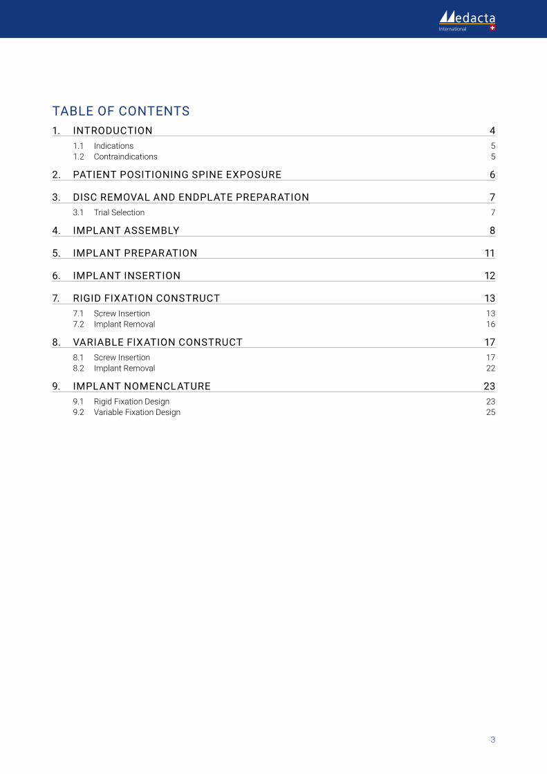
Locking and lag screws are offered to further complete the system. For each design both self-tapping and self-drilling screws are available. Locking screws are compatible with rigid fixation plate (purple) while lag screws are compatible with variable fixation plate (blue). Further fixation is required in the variable fixation construct with the antibackout screw (1B).
A - Rigid Fixation Design
B - Variable Fixation Design
1.
The cages are offered in PEEK plasma coated with a micrometric layer of Titanium (TiPEEK). The implants are fully coated except for the surfaces in contact with the plate or the inserter. Titanium marker pins allow for clear radiographic visualization.
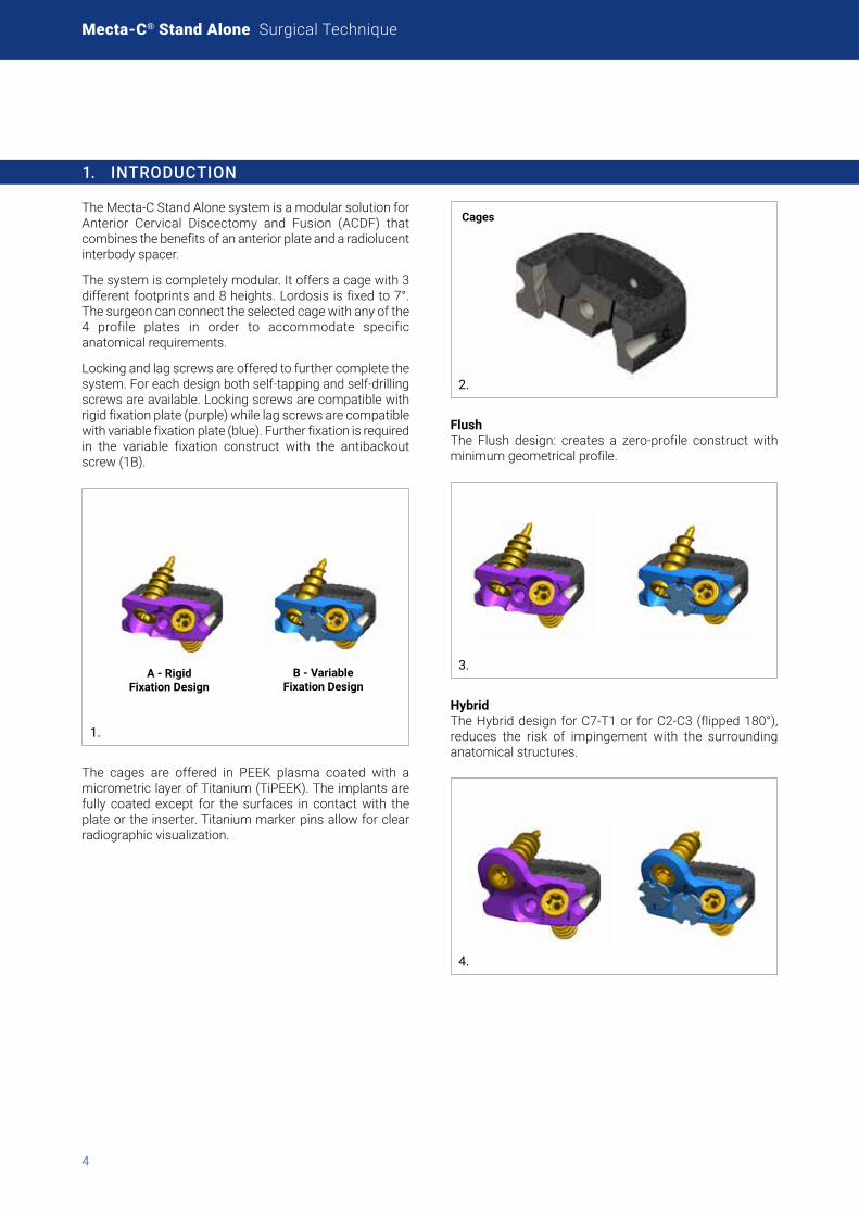
Cages
2.
Flush The Flush design: creates a zero-profile construct with minimum geometrical profile.
3.
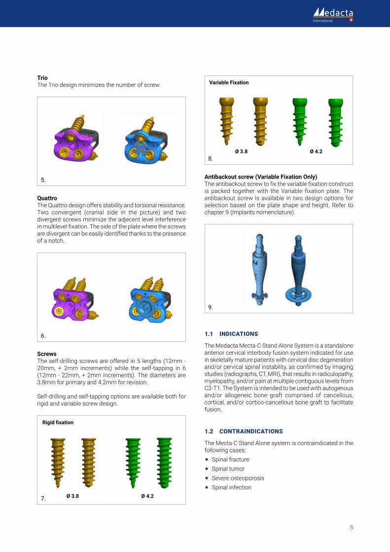
HybridThe Hybrid design for C7-T1 or for C2-C3 (flipped 180°), reduces the risk of impingement with the surrounding anatomical structures.
4.
5
Trio The Trio design minimizes the number of screw.
5.
QuattroThe Quattro design offers stability and torsional resistance. Two convergent (cranial side in the picture) and two divergent screws minimize the adjecent level interference in multilevel fixation. The side of the plate where the screws are divergent can be easily identified thanks to the presence of a notch.
6.
Screws The self-drilling screws are offered in 5 lengths (12mm - 20mm, + 2mm increments) while the self-tapping in 6 (12mm - 22mm, + 2mm increments). The diameters are 3.8mm for primary and 4.2mm for revision.
Self-drilling and self-tapping options are available both for rigid and variable screw design.
Ø 3.8 Ø 4.2
Rigid fixation
7.
Ø 3.8 Ø 4.2
Variable Fixation
8.
Antibackout screw (Variable Fixation Only)The antibackout screw to fix the variable fixation construct is packed together with the Variable fixation plate. The antibackout screw is available in two design options for selection based on the plate shape and height. Refer to chapter 9 (Implants nomenclature).
9.
1.1 INDICATIONS
The Medacta Mecta-C Stand Alone System is a standalone anterior cervical interbody fusion system indicated for use in skeletally mature patients with cervical disc degeneration and/or cervical spinal instability, as confirmed by imaging studies (radiographs, CT, MRI), that results in radiculopathy, myelopathy, and/or pain at multiple contiguous levels from C2-T1. The System is intended to be used with autogenous and/or allogeneic bone graft comprised of cancellous, cortical, and/or cortico-cancellous bone graft to facilitate fusion.
1.2 CONTRAINDICATIONS
The Mecta-C Stand Alone system is contraindicated in the following cases:
• Spinal fracture
• Spinal tumor
• Severe osteoporosis
• Spinal infection
Mecta-C® Stand Alone Surgical Technique
6
2. PATIENT POSITIONING SPINE EXPOSURE
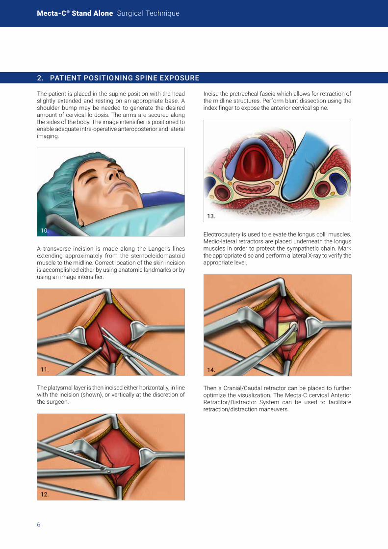
The patient is placed in the supine position with the head slightly extended and resting on an appropriate base. A shoulder bump may be needed to generate the desired amount of cervical lordosis. The arms are secured along the sides of the body. The image intensifier is positioned to enable adequate intra-operative anteroposterior and lateral imaging.
10.
A transverse incision is made along the Langer’s lines extending approximately from the sternocleidomastoid muscle to the midline. Correct location of the skin incision is accomplished either by using anatomic landmarks or by using an image intensifier.
11.
The platysmal layer is then incised either horizontally, in line with the incision (shown), or vertically at the discretion of the surgeon.
12.
Incise the pretracheal fascia which allows for retraction of the midline structures. Perform blunt dissection using the index finger to expose the anterior cervical spine.
13.
Electrocautery is used to elevate the longus colli muscles. Medio-lateral retractors are placed underneath the longus muscles in order to protect the sympathetic chain. Mark the appropriate disc and perform a lateral X-ray to verify the appropriate level.
14.
Then a Cranial/Caudal retractor can be placed to further optimize the visualization. The Mecta-C cervical Anterior Retractor/Distractor System can be used to facilitate retraction/distraction maneuvers.
7
3. DISC REMOVAL AND ENDPLATE PREPARATION
For effective visualization and removal of the disc, Caspar Pin distraction, or an equivalent distractor system, is recommended. This step also allows for restoration of segmental lordosis, if desired. Before distraction of the segment, the intervertebral disc should be incised and partially removed with curettes and pituitary rongeurs. Following distraction, complete removal of intervertebral disc material and cartilaginous endplates is then performed to expose the underlying bony endplate.
3.1 TRIAL SELECTION
Select the Trial that is most suitable for the disc space. Check the appropriate footprint and height.
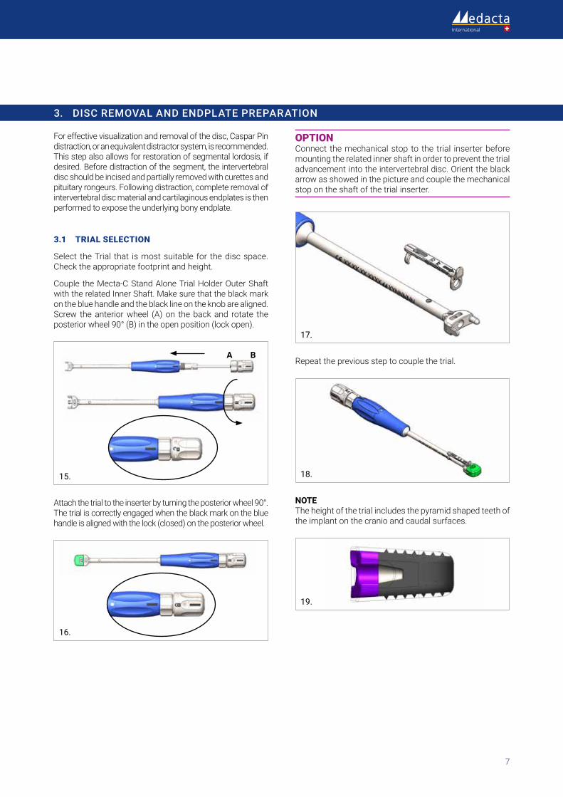
Couple the Mecta-C Stand Alone Trial Holder Outer Shaft with the related Inner Shaft. Make sure that the black mark on the blue handle and the black line on the knob are aligned. Screw the anterior wheel (A) on the back and rotate the posterior wheel 90° (B) in the open position (lock open).
A B
15.
Attach the trial to the inserter by turning the posterior wheel 90°. The trial is correctly engaged when the black mark on the blue handle is aligned with the lock (closed) on the posterior wheel.
16.
OPTION Connect the mechanical stop to the trial inserter before mounting the related inner shaft in order to prevent the trial advancement into the intervertebral disc. Orient the black arrow as showed in the picture and couple the mechanical stop on the shaft of the trial inserter.
17.
Repeat the previous step to couple the trial.
18.
NOTE The height of the trial includes the pyramid shaped teeth of the implant on the cranio and caudal surfaces.
19.
Mecta-C® Stand Alone Surgical Technique
8
4. IMPLANT ASSEMBLY
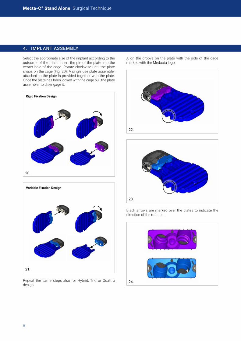
Select the appropriate size of the implant according to the outcome of the trials. Insert the pin of the plate into the center hole of the cage. Rotate clockwise until the plate snaps on the cage (Fig. 20). A single use plate assembler attached to the plate is provided together with the plate. Once the plate has been locked with the cage pull the plate assembler to disengage it.
Rigid Fixation Design
20.
Variable Fixation Design
21.
Repeat the same steps also for Hybrid, Trio or Quattro design.
Align the groove on the plate with the side of the cage marked with the Medacta logo.
22.
23.
Black arrows are marked over the plates to indicate the direction of the rotation.
24.
9
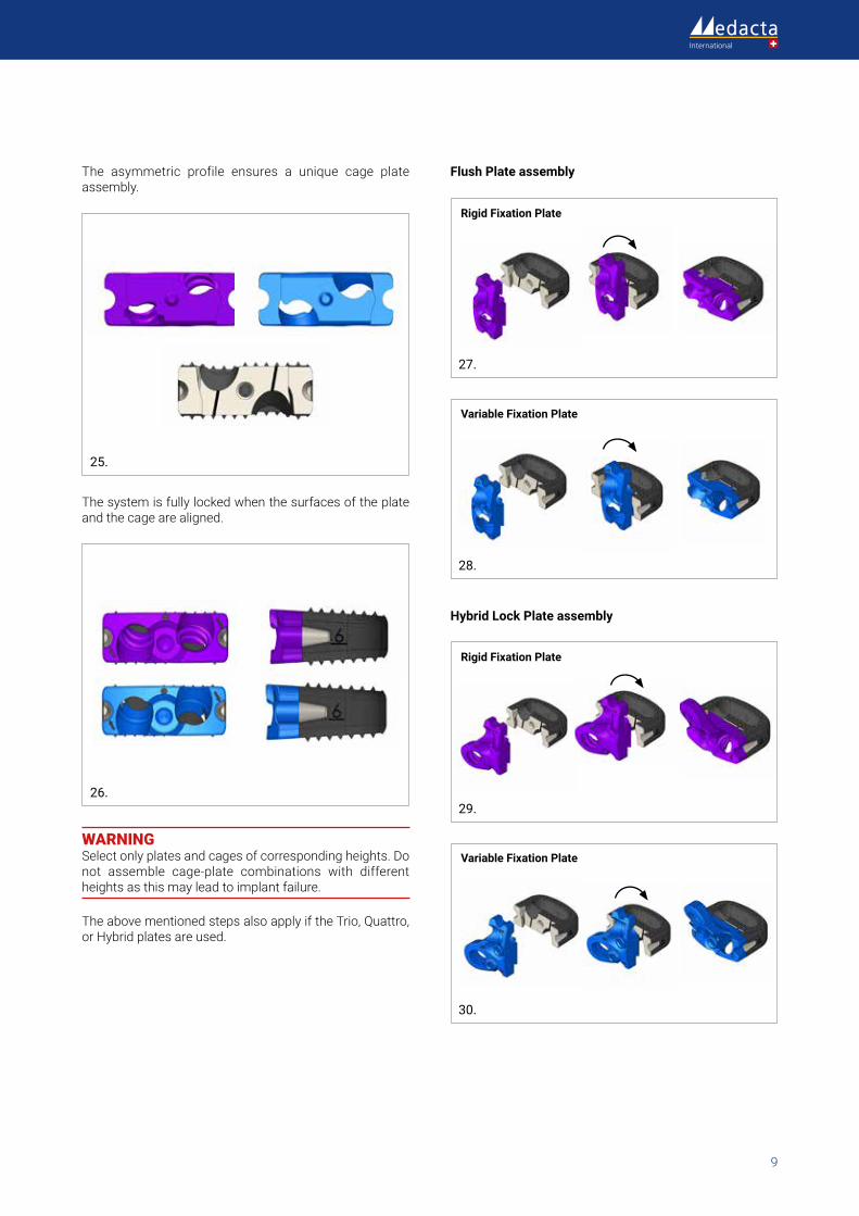
The asymmetric profile ensures a unique cage plate assembly.
25.
The system is fully locked when the surfaces of the plate and the cage are aligned.
26.
WARNING Select only plates and cages of corresponding heights. Do not assemble cage-plate combinations with different heights as this may lead to implant failure.
The above mentioned steps also apply if the Trio, Quattro, or Hybrid plates are used.
Flush Plate assembly
Rigid Fixation Plate
27.
Variable Fixation Plate
28.
Hybrid Lock Plate assembly
Rigid Fixation Plate
29.
Variable Fixation Plate
30.
Mecta-C® Stand Alone Surgical Technique
10
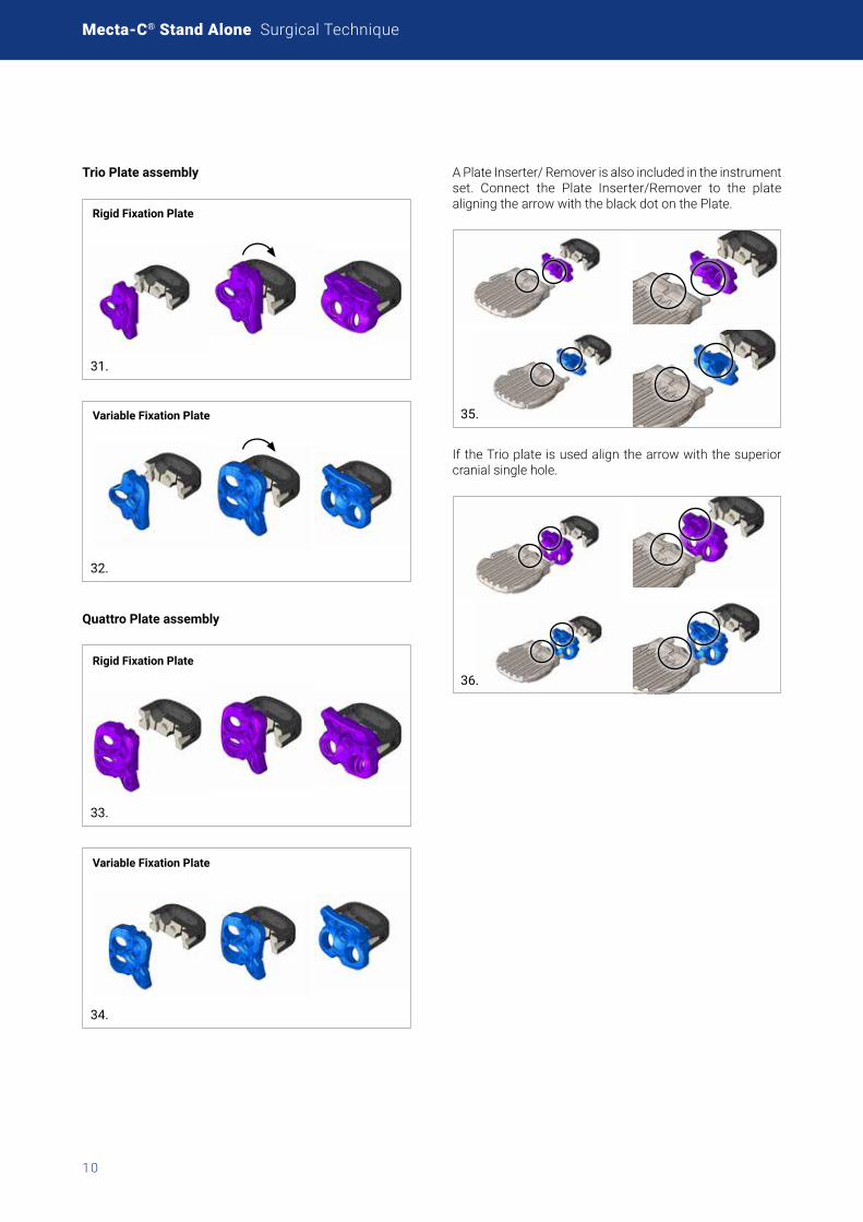
Trio Plate assembly
Rigid Fixation Plate
31.
Variable Fixation Plate
32.
Quattro Plate assembly
Rigid Fixation Plate
33.
Variable Fixation Plate
34.
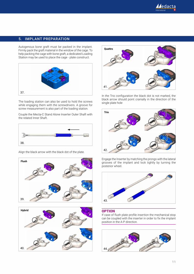
A Plate Inserter/ Remover is also included in the instrument set. Connect the Plate Inserter/Remover to the plate aligning the arrow with the black dot on the Plate.
35.
If the Trio plate is used align the arrow with the superior cranial single hole.
36.
11
5. IMPLANT PREPARATION
Autogenous bone graft must be packed in the implant. Firmly pack the graft material in the window of the cage. To help packing the cage with bone graft, a dedicated Loading Station may be used to place the cage - plate construct.
37.
The loading station can also be used to hold the screws while engaging them with the screwdrivers. A groove for screw measurement is also part of the loading station.
Couple the Mecta-C Stand Alone Inserter Outer Shaft with the related Inner Shaft.
38.
Align the black arrow with the black dot of the plate.
Flush
39.
Hybrid
40.
Quattro
41.
In the Trio configuration the black dot is not marked, the black arrow should point cranially in the direction of the single plate hole
Trio
42.
Engage the Inserter by matching the prongs with the lateral grooves of the implant and lock tightly by turning the posterior wheel.
43.
OPTION If case of flush plate profile insertion the mechanical stop can be coupled with the inserter in order to fix the implant position in the A-P direction.
44.
Mecta-C® Stand Alone Surgical Technique
12
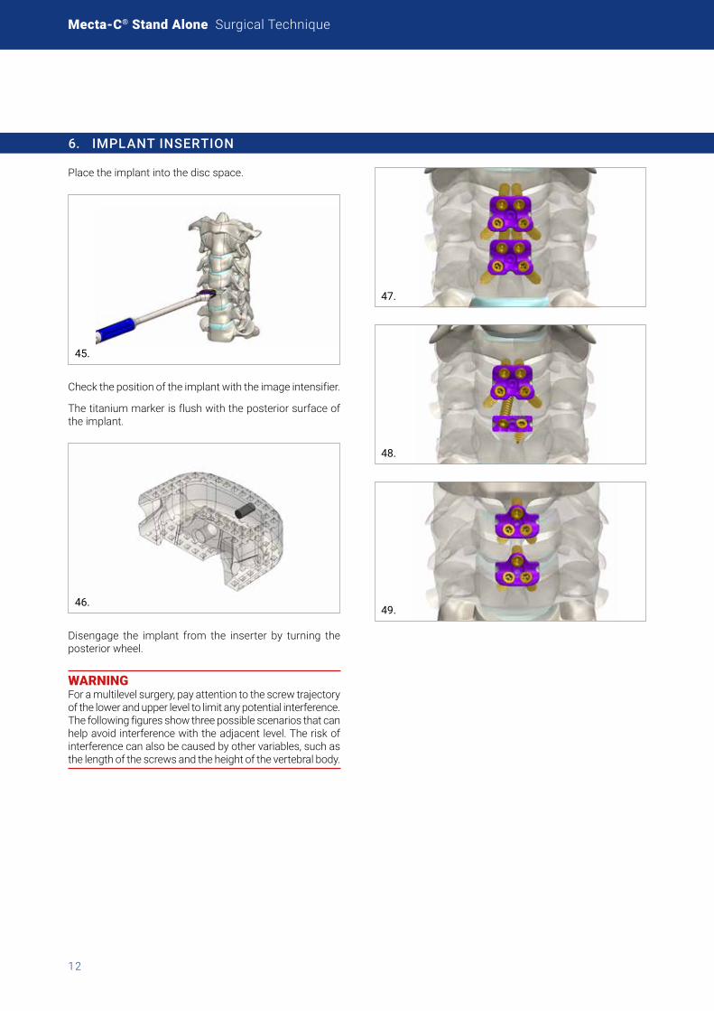
6. IMPLANT INSERTION
Place the implant into the disc space.
45.
Check the position of the implant with the image intensifier.
The titanium marker is flush with the posterior surface of the implant.
46.
Disengage the implant from the inserter by turning the posterior wheel.
WARNING For a multilevel surgery, pay attention to the screw trajectory of the lower and upper level to limit any potential interference. The following figures show three possible scenarios that can help avoid interference with the adjacent level. The risk of interference can also be caused by other variables, such as the length of the screws and the height of the vertebral body.
47.
48.
49.
13
7. RIGID FIXATION CONSTRUCT
The following paragraphs describe the steps to insert the screw with the Rigid Fixation Design. Rigid Fixation Plate and screws “options”are summarized in the picture here below.
Flush
Trio
Hybrid
Quattro
Plate
50.
Ø 3.8 Ø 4.2
Screws
51.
All the lock design instruments have a violet strip and “lock” marked along the shaf. See, as example Fig. 52.
Tissue protection sleeve (on demand)
52.
Instruments without these marks are compatible with both the lock and lag designs.
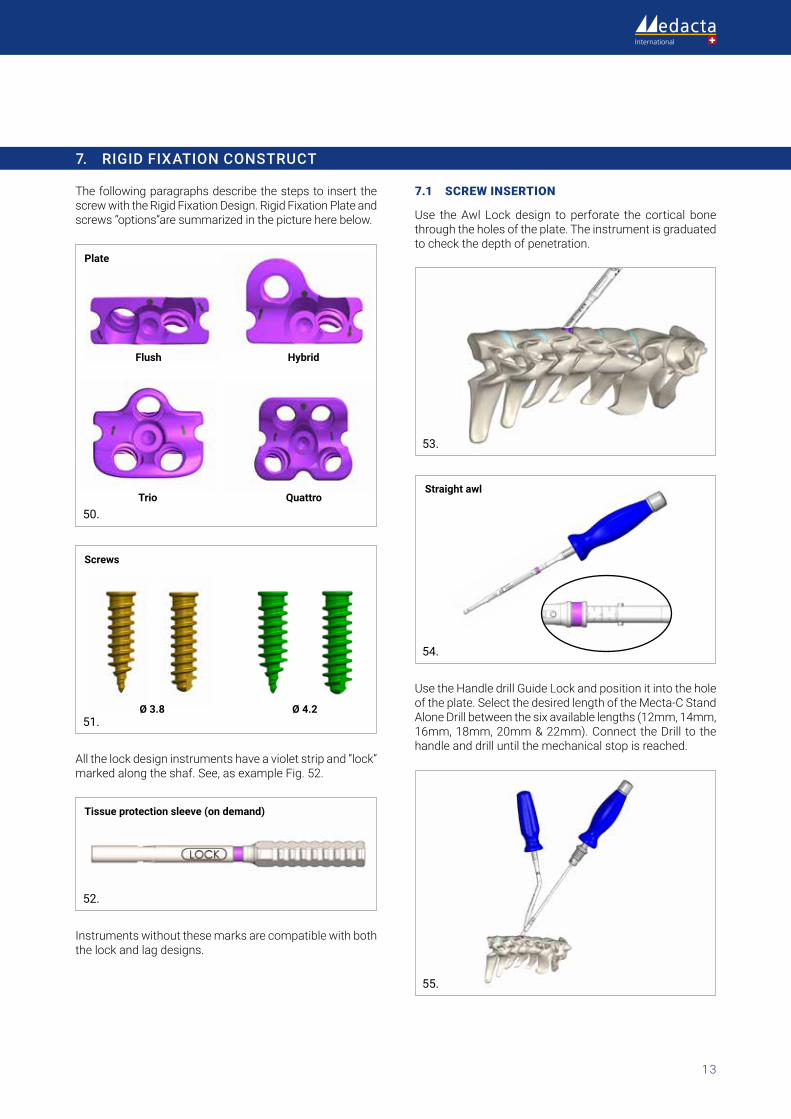
7.1 SCREW INSERTION
Use the Awl Lock design to perforate the cortical bone through the holes of the plate. The instrument is graduated to check the depth of penetration.
53.
Straight awl
54.
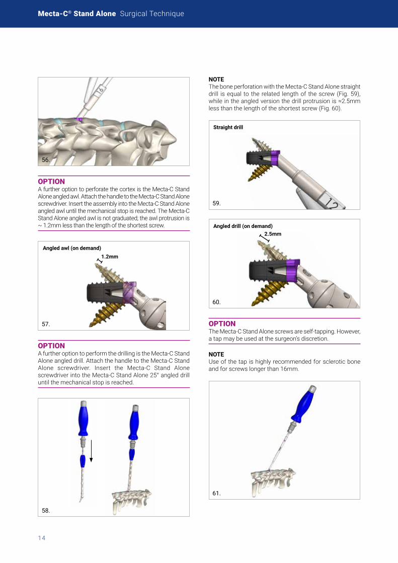
Use the Handle drill Guide Lock and position it into the hole of the plate. Select the desired length of the Mecta-C Stand Alone Drill between the six available lengths (12mm, 14mm, 16mm, 18mm, 20mm & 22mm). Connect the Drill to the handle and drill until the mechanical stop is reached.
55.
Mecta-C® Stand Alone Surgical Technique
14
56.
OPTION A further option to perforate the cortex is the Mecta-C Stand Alone angled awl. Attach the handle to the Mecta-C Stand Alone screwdriver. Insert the assembly into the Mecta-C Stand Alone angled awl until the mechanical stop is reached. The Mecta-C Stand Alone angled awl is not graduated; the awl protrusion is ~ 1.2mm less than the length of the shortest screw.
1.2mmAngled awl (on demand)
57.
OPTION A further option to perform the drilling is the Mecta-C Stand Alone angled drill. Attach the handle to the Mecta-C Stand Alone screwdriver. Insert the Mecta-C Stand Alone screwdriver into the Mecta-C Stand Alone 25° angled drill until the mechanical stop is reached.
58.
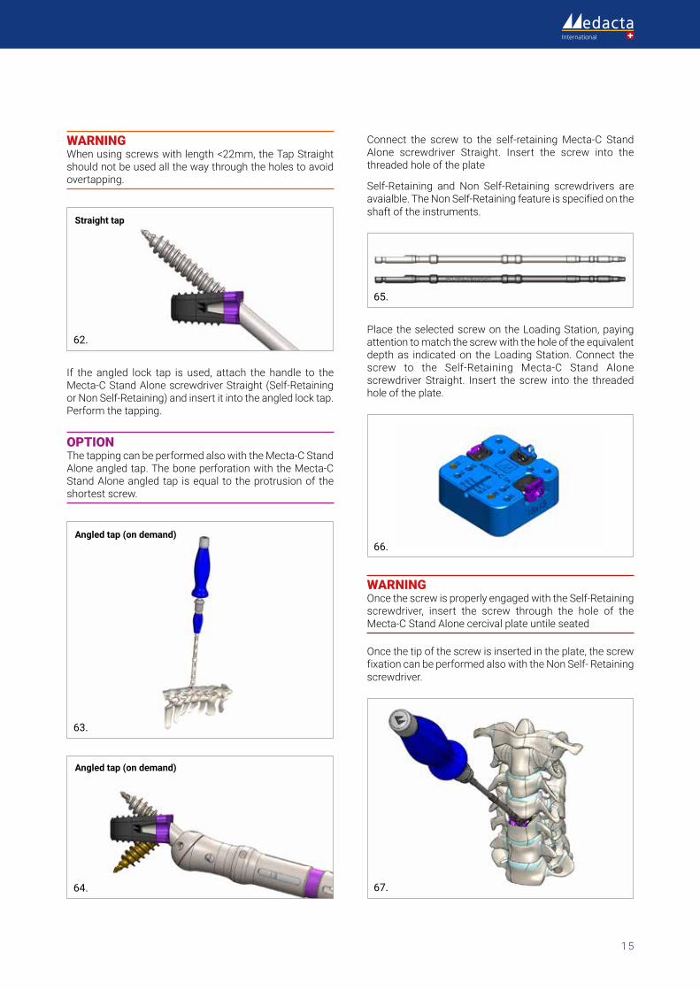
NOTE The bone perforation with the Mecta-C Stand Alone straight drill is equal to the related length of the screw (Fig. 59), while in the angled version the drill protrusion is ≈2.5mm less than the length of the shortest screw (Fig. 60).
Straight drill
59.
2.5mmAngled drill (on demand)
60.
OPTION The Mecta-C Stand Alone screws are self-tapping. However, a tap may be used at the surgeon’s discretion.
NOTE Use of the tap is highly recommended for sclerotic bone and for screws longer than 16mm.
61.
15
WARNING When using screws with length <22mm, the Tap Straight should not be used all the way through the holes to avoid overtapping.
Straight tap
62.
If the angled lock tap is used, attach the handle to the Mecta-C Stand Alone screwdriver Straight (Self-Retaining or Non Self-Retaining) and insert it into the angled lock tap. Perform the tapping.
OPTION The tapping can be performed also with the Mecta-C Stand Alone angled tap. The bone perforation with the Mecta-C Stand Alone angled tap is equal to the protrusion of the shortest screw.
Angled tap (on demand)
63.
Angled tap (on demand)
64.
Connect the screw to the self-retaining Mecta-C Stand Alone screwdriver Straight. Insert the screw into the threaded hole of the plate
Self-Retaining and Non Self-Retaining screwdrivers are avaialble. The Non Self-Retaining feature is specified on the shaft of the instruments.
65.
Place the selected screw on the Loading Station, paying attention to match the screw with the hole of the equivalent depth as indicated on the Loading Station. Connect the screw to the Self-Retaining Mecta-C Stand Alone screwdriver Straight. Insert the screw into the threaded hole of the plate.
66.
WARNING Once the screw is properly engaged with the Self-Retaining screwdriver, insert the screw through the hole of the Mecta-C Stand Alone cercival plate untile seated
Once the tip of the screw is inserted in the plate, the screw fixation can be performed also with the Non Self- Retaining screwdriver.
67.
Mecta-C® Stand Alone Surgical Technique
16
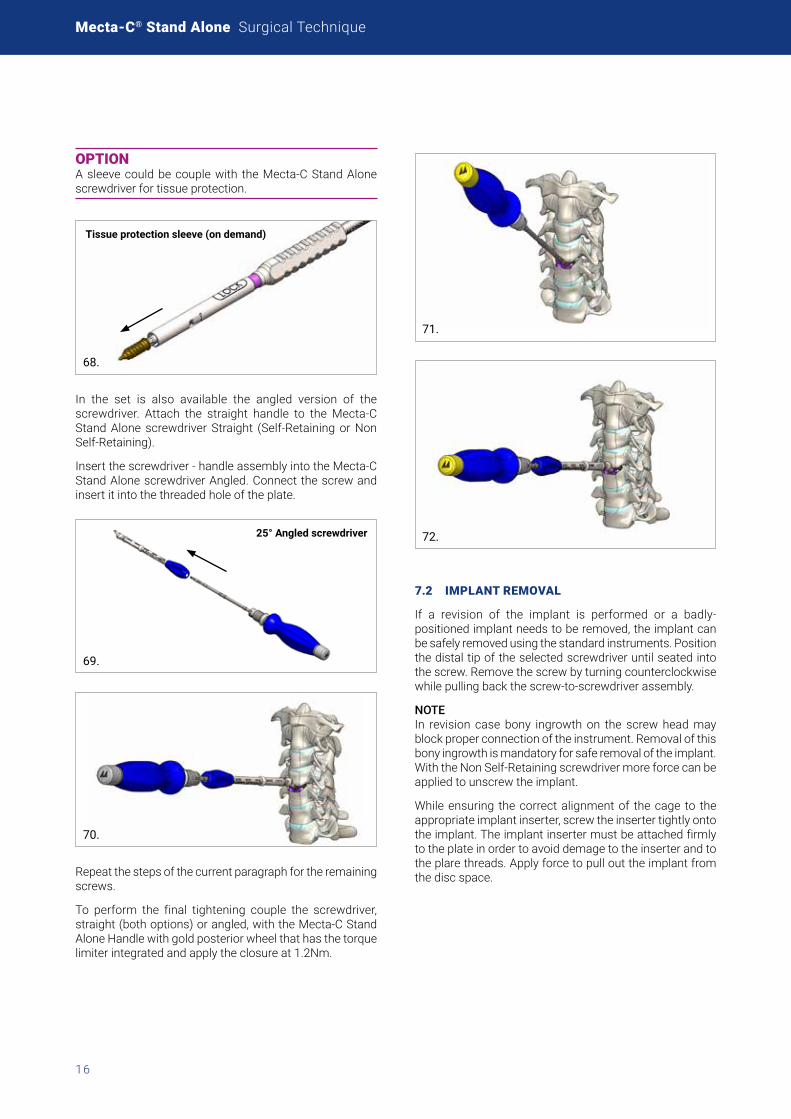
OPTION A sleeve could be couple with the Mecta-C Stand Alone screwdriver for tissue protection.
Tissue protection sleeve (on demand)
68.
In the set is also available the angled version of the screwdriver. Attach the straight handle to the Mecta-C Stand Alone screwdriver Straight (Self-Retaining or Non Self-Retaining).
Insert the screwdriver - handle assembly into the Mecta-C Stand Alone screwdriver Angled. Connect the screw and insert it into the threaded hole of the plate.
25° Angled screwdriver
69.
70.
Repeat the steps of the current paragraph for the remaining screws.
To perform the final tightening couple the screwdriver, straight (both options) or angled, with the Mecta-C Stand Alone Handle with gold posterior wheel that has the torque limiter integrated and apply the closure at 1.2Nm.
71.
72.
7.2 IMPLANT REMOVAL
If a revision of the implant is performed or a badly-positioned implant needs to be removed, the implant can be safely removed using the standard instruments. Position the distal tip of the selected screwdriver until seated into the screw. Remove the screw by turning counterclockwise while pulling back the screw-to-screwdriver assembly.
NOTE In revision case bony ingrowth on the screw head may block proper connection of the instrument. Removal of this bony ingrowth is mandatory for safe removal of the implant. With the Non Self-Retaining screwdriver more force can be applied to unscrew the implant.
While ensuring the correct alignment of the cage to the appropriate implant inserter, screw the inserter tightly onto the implant. The implant inserter must be attached firmly to the plate in order to avoid demage to the inserter and to the plare threads. Apply force to pull out the implant from the disc space.
17
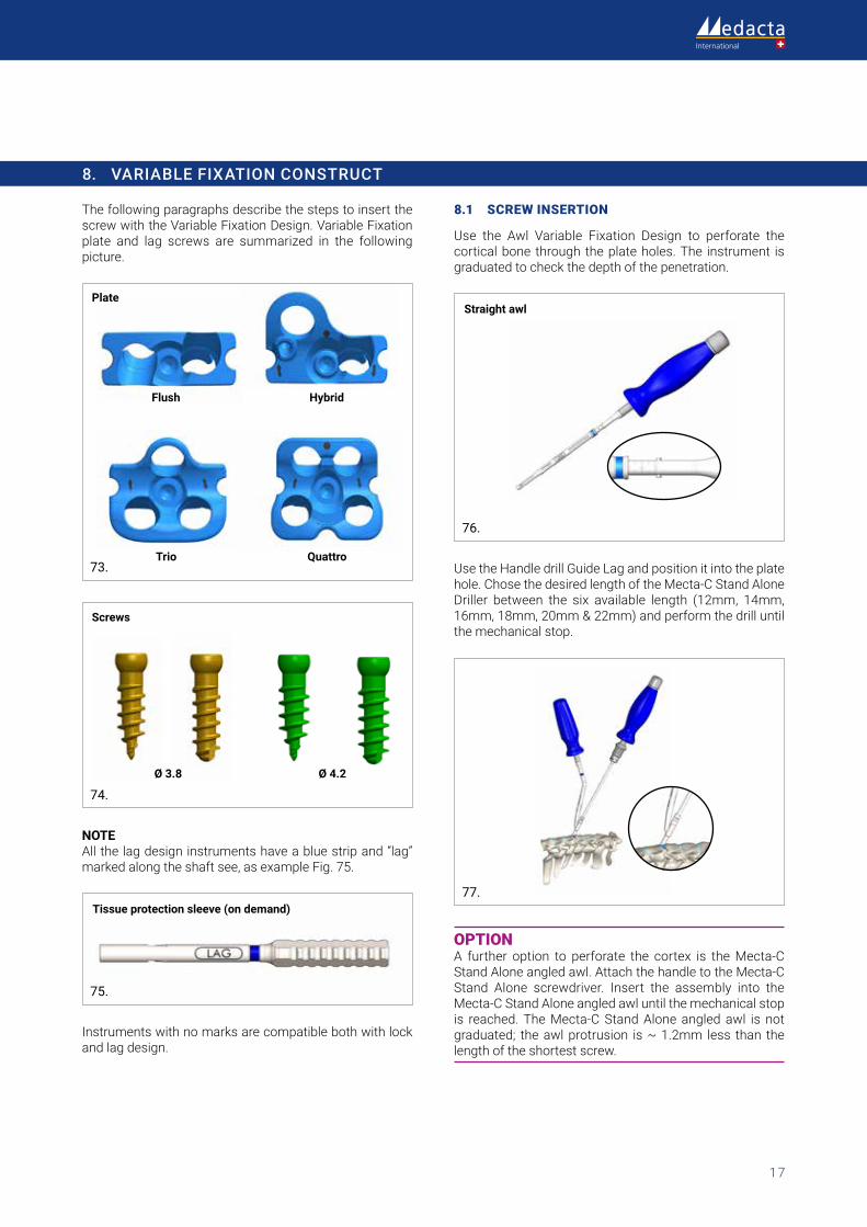
8. VARIABLE FIXATION CONSTRUCT
The following paragraphs describe the steps to insert the screw with the Variable Fixation Design. Variable Fixation plate and lag screws are summarized in the following picture.
Flush
Trio
Hybrid
Quattro
Plate
73.
Ø 3.8 Ø 4.2
Screws
74.
NOTE All the lag design instruments have a blue strip and “lag” marked along the shaft see, as example Fig. 75.
Tissue protection sleeve (on demand)
75.
Instruments with no marks are compatible both with lock and lag design.
8.1 SCREW INSERTION
Use the Awl Variable Fixation Design to perforate the cortical bone through the plate holes. The instrument is graduated to check the depth of the penetration.
Straight awl
76.
Use the Handle drill Guide Lag and position it into the plate hole. Chose the desired length of the Mecta-C Stand Alone Driller between the six available length (12mm, 14mm, 16mm, 18mm, 20mm & 22mm) and perform the drill until the mechanical stop.
77.
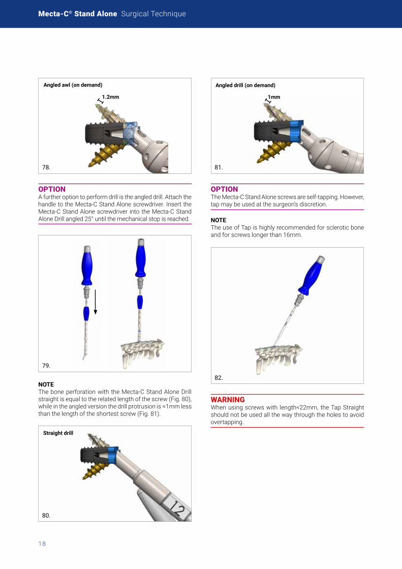
OPTION A further option to perforate the cortex is the Mecta-C Stand Alone angled awl. Attach the handle to the Mecta-C Stand Alone screwdriver. Insert the assembly into the Mecta-C Stand Alone angled awl until the mechanical stop is reached. The Mecta-C Stand Alone angled awl is not graduated; the awl protrusion is ~ 1.2mm less than the length of the shortest screw.
Mecta-C® Stand Alone Surgical Technique
18
1.2mm
Angled awl (on demand)
78.
OPTION A further option to perform drill is the angled drill. Attach the handle to the Mecta-C Stand Alone screwdriver. Insert the Mecta-C Stand Alone screwdriver into the Mecta-C Stand Alone Drill angled 25° until the mechanical stop is reached.
79.
NOTE The bone perforation with the Mecta-C Stand Alone Drill straight is equal to the related length of the screw (Fig. 80), while in the angled version the drill protrusion is ≈1mm less than the length of the shortest screw (Fig. 81).
Straight drill
80.
1mm
Angled drill (on demand)
81.
OPTION The Mecta-C Stand Alone screws are self-tapping. However, tap may be used at the surgeon’s discretion.
NOTE The use of Tap is highly recommended for sclerotic bone and for screws longer than 16mm.
82.
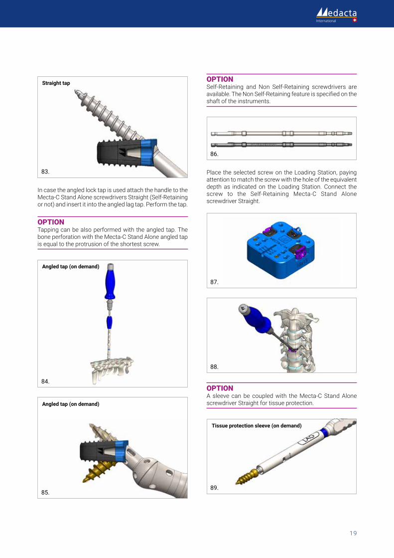
WARNING When using screws with length<22mm, the Tap Straight should not be used all the way through the holes to avoid overtapping.
19
Straight tap
83.
In case the angled lock tap is used attach the handle to the Mecta-C Stand Alone screwdrivers Straight (Self-Retaining or not) and insert it into the angled lag tap. Perform the tap.
OPTION Tapping can be also performed with the angled tap. The bone perforation with the Mecta-C Stand Alone angled tap is equal to the protrusion of the shortest screw.
Angled tap (on demand)
84.
Angled tap (on demand)
85.
OPTION Self-Retaining and Non Self-Retaining screwdrivers are available. The Non Self-Retaining feature is specified on the shaft of the instruments.
86.
Place the selected screw on the Loading Station, paying attention to match the screw with the hole of the equivalent depth as indicated on the Loading Station. Connect the screw to the Self-Retaining Mecta-C Stand Alone screwdriver Straight.
87.
88.
OPTION A sleeve can be coupled with the Mecta-C Stand Alone screwdriver Straight for tissue protection.
Tissue protection sleeve (on demand)
89.
Mecta-C® Stand Alone Surgical Technique
20
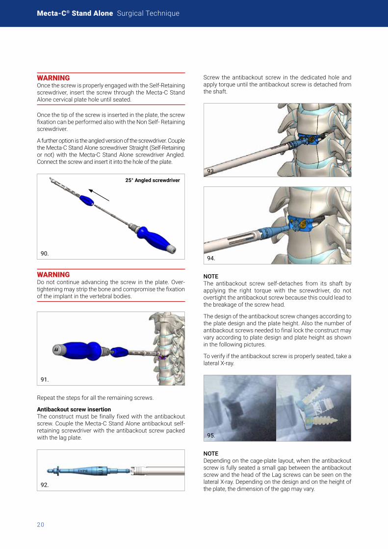
WARNING Once the screw is properly engaged with the Self-Retaining screwdriver, insert the screw through the Mecta-C Stand Alone cervical plate hole until seated.
Once the tip of the screw is inserted in the plate, the screw fixation can be performed also with the Non Self- Retaining screwdriver.
A further option is the angled version of the screwdriver. Couple the Mecta-C Stand Alone screwdriver Straight (Self-Retaining or not) with the Mecta-C Stand Alone screwdriver Angled. Connect the screw and insert it into the hole of the plate.
25° Angled screwdriver
90.
WARNING Do not continue advancing the screw in the plate. Over-tightening may strip the bone and compromise the fixation of the implant in the vertebral bodies.
91.
Repeat the steps for all the remaining screws.
Antibackout screw insertionThe construct must be finally fixed with the antibackout screw. Couple the Mecta-C Stand Alone antibackout self-retaining screwdriver with the antibackout screw packed with the lag plate.
92.
Screw the antibackout screw in the dedicated hole and apply torque until the antibackout screw is detached from the shaft.
93.
94.
NOTE The antibackout screw self-detaches from its shaft by applying the right torque with the screwdriver, do not overtight the antibackout screw because this could lead to the breakage of the screw head.
The design of the antibackout screw changes according to the plate design and the plate height. Also the number of antibackout screws needed to final lock the construct may vary according to plate design and plate height as shown in the following pictures.
To verify if the antibackout screw is properly seated, take a lateral X-ray.
95.
NOTE Depending on the cage-plate layout, when the antibackout screw is fully seated a small gap between the antibackout screw and the head of the Lag screws can be seen on the lateral X-ray. Depending on the design and on the height of the plate, the dimension of the gap may vary.
21
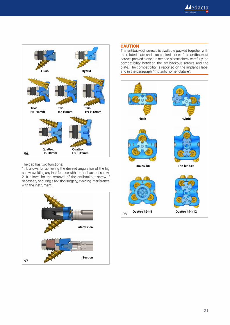
Flush
Quattro: H5-H8mm
Quattro: H9-H12mm
Hybrid
Trio: H5-H6mm
Trio: H7-H8mm
Trio: H9-H12mm
96.
The gap has two functions:1. It allows for achieving the desired angulation of the lag screw, avoiding any interference with the antibackout screw. 2. It allows for the removal of the antibackout screw if necessary or during a revision surgery, avoiding interference with the instrument.
Lateral view
Section97.
CAUTION The antibackout screws is available packed together with the related plate and also packed alone. If the antibackout screws packed alone are needed please check carefully the compatibility between the antibackout screws and the plate. The compatibility is reported on the implant’s label and in the paragraph “implants nomenclature”.
Flush
Trio h5-h8
Quattro h5-h8
Hybrid
Trio h9-h12
Quattro h9-h1298.
Mecta-C® Stand Alone Surgical Technique
22
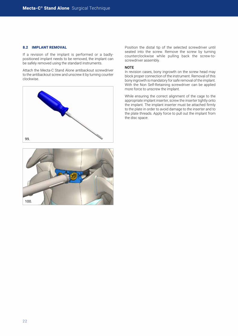
8.2 IMPLANT REMOVAL
If a revision of the implant is performed or a badly-positioned implant needs to be removed, the implant can be safely removed using the standard instruments.
Attach the Mecta-C Stand Alone antibackout screwdriver to the antibackout screw and unscrew it by turning counter clockwise.
99.
100.
Position the distal tip of the selected screwdriver until seated into the screw. Remove the screw by turning counterclockwise while pulling back the screw-to-screwdriver assembly.
NOTE In revision cases, bony ingrowth on the screw head may block proper connection of the instrument. Removal of this bony ingrowth is mandatory for safe removal of the implant. With the Non Self-Retaining screwdriver can be applied more force to unscrew the implant.
While ensuring the correct alignment of the cage to the appropriate implant inserter, screw the inserter tightly onto the implant. The implant inserter must be attached firmly to the plate in order to avoid damage to the inserter and to the plate threads. Apply force to pull out the implant from the disc space.
23
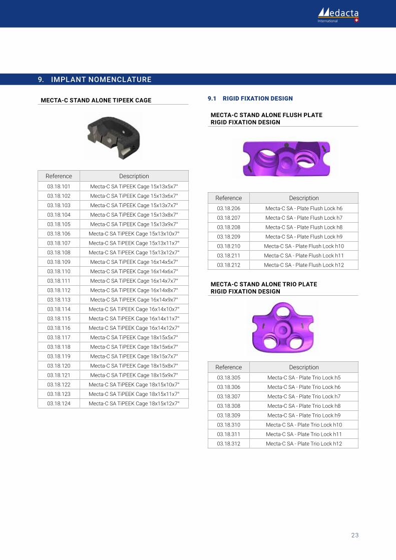
9. IMPLANT NOMENCLATURE
MECTA-C STAND ALONE TIPEEK CAGE
Reference Description
03.18.101 Mecta-C SA TiPEEK Cage 15x13x5x7°
03.18.102 Mecta-C SA TiPEEK Cage 15x13x6x7°
03.18.103 Mecta-C SA TiPEEK Cage 15x13x7x7°
03.18.104 Mecta-C SA TiPEEK Cage 15x13x8x7°
03.18.105 Mecta-C SA TiPEEK Cage 15x13x9x7°
03.18.106 Mecta-C SA TiPEEK Cage 15x13x10x7°
03.18.107 Mecta-C SA TiPEEK Cage 15x13x11x7°
03.18.108 Mecta-C SA TiPEEK Cage 15x13x12x7°
03.18.109 Mecta-C SA TiPEEK Cage 16x14x5x7°
03.18.110 Mecta-C SA TiPEEK Cage 16x14x6x7°
03.18.111 Mecta-C SA TiPEEK Cage 16x14x7x7°
03.18.112 Mecta-C SA TiPEEK Cage 16x14x8x7°
03.18.113 Mecta-C SA TiPEEK Cage 16x14x9x7°
03.18.114 Mecta-C SA TiPEEK Cage 16x14x10x7°
03.18.115 Mecta-C SA TiPEEK Cage 16x14x11x7°
03.18.116 Mecta-C SA TiPEEK Cage 16x14x12x7°
03.18.117 Mecta-C SA TiPEEK Cage 18x15x5x7°
03.18.118 Mecta-C SA TiPEEK Cage 18x15x6x7°
03.18.119 Mecta-C SA TiPEEK Cage 18x15x7x7°
03.18.120 Mecta-C SA TiPEEK Cage 18x15x8x7°
03.18.121 Mecta-C SA TiPEEK Cage 18x15x9x7°
03.18.122 Mecta-C SA TiPEEK Cage 18x15x10x7°
03.18.123 Mecta-C SA TiPEEK Cage 18x15x11x7°
03.18.124 Mecta-C SA TiPEEK Cage 18x15x12x7°
9.1 RIGID FIXATION DESIGN
MECTA-C STAND ALONE FLUSH PLATE RIGID FIXATION DESIGN
Reference Description
03.18.206 Mecta-C SA - Plate Flush Lock h6
03.18.207 Mecta-C SA - Plate Flush Lock h7
03.18.208 Mecta-C SA - Plate Flush Lock h8
03.18.209 Mecta-C SA - Plate Flush Lock h9
03.18.210 Mecta-C SA - Plate Flush Lock h10
03.18.211 Mecta-C SA - Plate Flush Lock h11
03.18.212 Mecta-C SA - Plate Flush Lock h12
MECTA-C STAND ALONE TRIO PLATE RIGID FIXATION DESIGN
Reference Description
03.18.305 Mecta-C SA - Plate Trio Lock h5
03.18.306 Mecta-C SA - Plate Trio Lock h6
03.18.307 Mecta-C SA - Plate Trio Lock h7
03.18.308 Mecta-C SA - Plate Trio Lock h8
03.18.309 Mecta-C SA - Plate Trio Lock h9
03.18.310 Mecta-C SA - Plate Trio Lock h10
03.18.311 Mecta-C SA - Plate Trio Lock h11
03.18.312 Mecta-C SA - Plate Trio Lock h12
Mecta-C® Stand Alone Surgical Technique
24
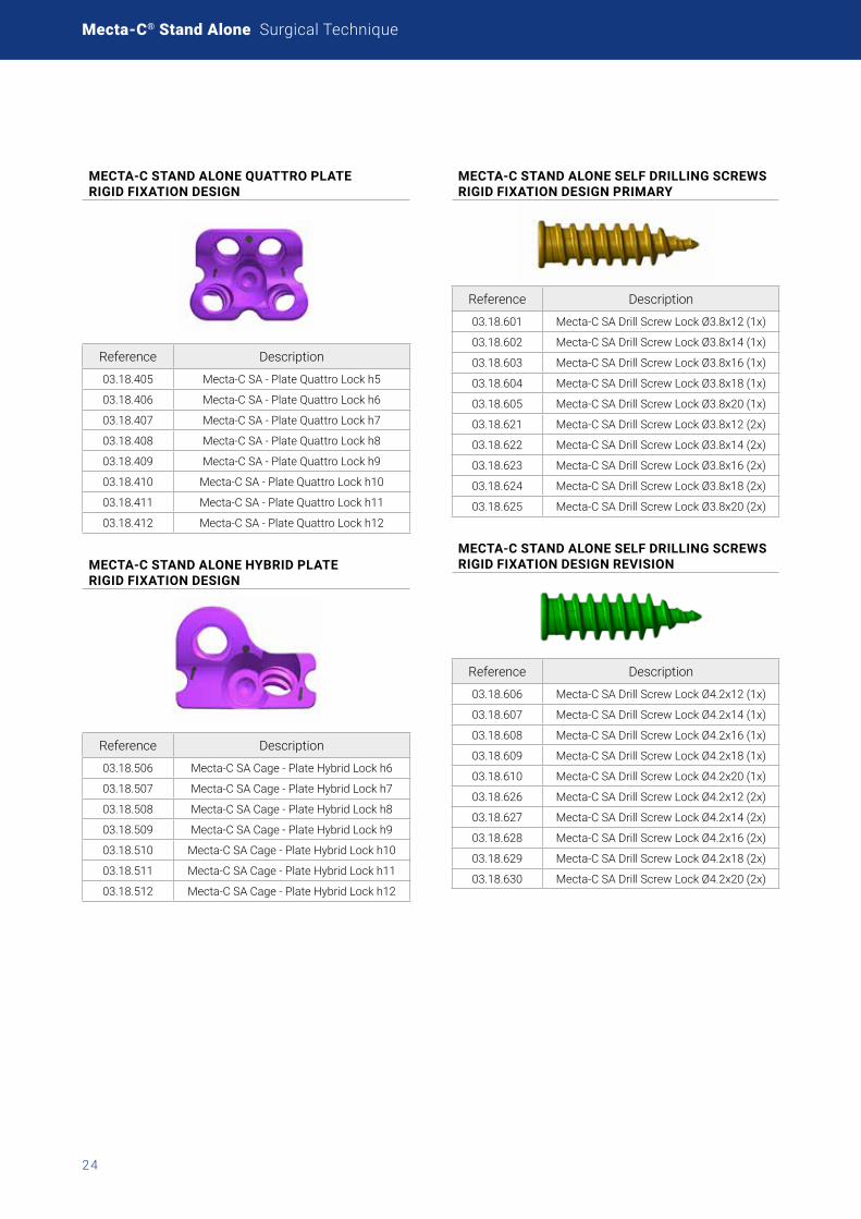
MECTA-C STAND ALONE QUATTRO PLATE RIGID FIXATION DESIGN
Reference Description
03.18.405 Mecta-C SA - Plate Quattro Lock h5
03.18.406 Mecta-C SA - Plate Quattro Lock h6
03.18.407 Mecta-C SA - Plate Quattro Lock h7
03.18.408 Mecta-C SA - Plate Quattro Lock h8
03.18.409 Mecta-C SA - Plate Quattro Lock h9
03.18.410 Mecta-C SA - Plate Quattro Lock h10
03.18.411 Mecta-C SA - Plate Quattro Lock h11
03.18.412 Mecta-C SA - Plate Quattro Lock h12
MECTA-C STAND ALONE HYBRID PLATE RIGID FIXATION DESIGN
Reference Description
03.18.506 Mecta-C SA Cage - Plate Hybrid Lock h6
03.18.507 Mecta-C SA Cage - Plate Hybrid Lock h7
03.18.508 Mecta-C SA Cage - Plate Hybrid Lock h8
03.18.509 Mecta-C SA Cage - Plate Hybrid Lock h9
03.18.510 Mecta-C SA Cage - Plate Hybrid Lock h10
03.18.511 Mecta-C SA Cage - Plate Hybrid Lock h11
03.18.512 Mecta-C SA Cage - Plate Hybrid Lock h12
MECTA-C STAND ALONE SELF DRILLING SCREWS RIGID FIXATION DESIGN PRIMARY
Reference Description
03.18.601 Mecta-C SA Drill Screw Lock Ø3.8x12 (1x)
03.18.602 Mecta-C SA Drill Screw Lock Ø3.8x14 (1x)
03.18.603 Mecta-C SA Drill Screw Lock Ø3.8x16 (1x)
03.18.604 Mecta-C SA Drill Screw Lock Ø3.8x18 (1x)
03.18.605 Mecta-C SA Drill Screw Lock Ø3.8x20 (1x)
03.18.621 Mecta-C SA Drill Screw Lock Ø3.8x12 (2x)
03.18.622 Mecta-C SA Drill Screw Lock Ø3.8x14 (2x)
03.18.623 Mecta-C SA Drill Screw Lock Ø3.8x16 (2x)
03.18.624 Mecta-C SA Drill Screw Lock Ø3.8x18 (2x)
03.18.625 Mecta-C SA Drill Screw Lock Ø3.8x20 (2x)
MECTA-C STAND ALONE SELF DRILLING SCREWS RIGID FIXATION DESIGN REVISION
Reference Description
03.18.606 Mecta-C SA Drill Screw Lock Ø4.2x12 (1x)
03.18.607 Mecta-C SA Drill Screw Lock Ø4.2x14 (1x)
03.18.608 Mecta-C SA Drill Screw Lock Ø4.2x16 (1x)
03.18.609 Mecta-C SA Drill Screw Lock Ø4.2x18 (1x)
03.18.610 Mecta-C SA Drill Screw Lock Ø4.2x20 (1x)
03.18.626 Mecta-C SA Drill Screw Lock Ø4.2x12 (2x)
03.18.627 Mecta-C SA Drill Screw Lock Ø4.2x14 (2x)
03.18.628 Mecta-C SA Drill Screw Lock Ø4.2x16 (2x)
03.18.629 Mecta-C SA Drill Screw Lock Ø4.2x18 (2x)
03.18.630 Mecta-C SA Drill Screw Lock Ø4.2x20 (2x)
25
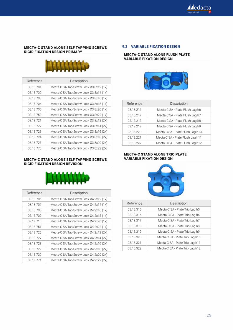
MECTA-C STAND ALONE SELF TAPPING SCREWS RIGID FIXATION DESIGN PRIMARY
Reference Description
03.18.701 Mecta-C SA Tap Screw Lock Ø3.8x12 (1x)
03.18.702 Mecta-C SA Tap Screw Lock Ø3.8x14 (1x)
03.18.703 Mecta-C SA Tap Screw Lock Ø3.8x16 (1x)
03.18.704 Mecta-C SA Tap Screw Lock Ø3.8x18 (1x)
03.18.705 Mecta-C SA Tap Screw Lock Ø3.8x20 (1x)
03.18.750 Mecta-C SA Tap Screw Lock Ø3.8x22 (1x)
03.18.721 Mecta-C SA Tap Screw Lock Ø3.8x12 (2x)
03.18.722 Mecta-C SA Tap Screw Lock Ø3.8x14 (2x)
03.18.723 Mecta-C SA Tap Screw Lock Ø3.8x16 (2x)
03.18.724 Mecta-C SA Tap Screw Lock Ø3.8x18 (2x)
03.18.725 Mecta-C SA Tap Screw Lock Ø3.8x20 (2x)
03.18.770 Mecta-C SA Tap Screw Lock Ø3.8x22 (2x)
MECTA-C STAND ALONE SELF TAPPING SCREWS RIGID FIXATION DESIGN REVISION
Reference Description
03.18.706 Mecta-C SA Tap Screw Lock Ø4.2x12 (1x)
03.18.707 Mecta-C SA Tap Screw Lock Ø4.2x14 (1x)
03.18.708 Mecta-C SA Tap Screw Lock Ø4.2x16 (1x)
03.18.709 Mecta-C SA Tap Screw Lock Ø4.2x18 (1x)
03.18.710 Mecta-C SA Tap Screw Lock Ø4.2x20 (1x)
03.18.751 Mecta-C SA Tap Screw Lock Ø4.2x22 (1x)
03.18.726 Mecta-C SA Tap Screw Lock Ø4.2x12 (2x)
03.18.727 Mecta-C SA Tap Screw Lock Ø4.2x14 (2x)
03.18.728 Mecta-C SA Tap Screw Lock Ø4.2x16 (2x)
03.18.729 Mecta-C SA Tap Screw Lock Ø4.2x18 (2x)
03.18.730 Mecta-C SA Tap Screw Lock Ø4.2x20 (2x)
03.18.771 Mecta-C SA Tap Screw Lock Ø4.2x22 (2x)
9.2 VARIABLE FIXATION DESIGN
MECTA-C STAND ALONE FLUSH PLATE VARIABLE FIXATION DESIGN
Reference Description
03.18.216 Mecta-C SA - Plate Flush Lag h6
03.18.217 Mecta-C SA - Plate Flush Lag h7
03.18.218 Mecta-C SA - Plate Flush Lag h8
03.18.219 Mecta-C SA - Plate Flush Lag h9
03.18.220 Mecta-C SA - Plate Flush Lag h10
03.18.221 Mecta-C SA - Plate Flush Lag h11
03.18.222 Mecta-C SA - Plate Flush Lag h12
MECTA-C STAND ALONE TRIO PLATEVARIABLE FIXATION DESIGN
Reference Description
03.18.315 Mecta-C SA - Plate Trio Lag h5
03.18.316 Mecta-C SA - Plate Trio Lag h6
03.18.317 Mecta-C SA - Plate Trio Lag h7
03.18.318 Mecta-C SA - Plate Trio Lag h8
03.18.319 Mecta-C SA - Plate Trio Lag h9
03.18.320 Mecta-C SA - Plate Trio Lag h10
03.18.321 Mecta-C SA - Plate Trio Lag h11
03.18.322 Mecta-C SA - Plate Trio Lag h12
Mecta-C® Stand Alone Surgical Technique
26
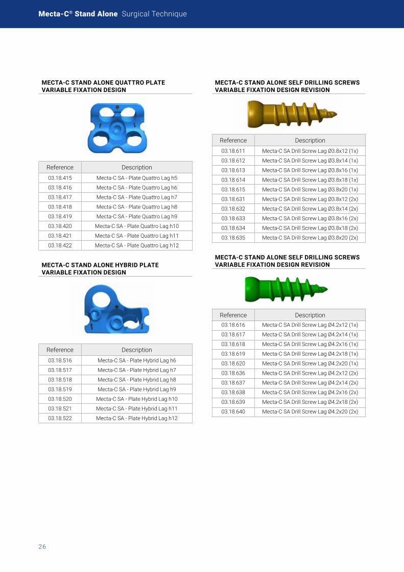
MECTA-C STAND ALONE QUATTRO PLATEVARIABLE FIXATION DESIGN
Reference Description
03.18.415 Mecta-C SA - Plate Quattro Lag h5
03.18.416 Mecta-C SA - Plate Quattro Lag h6
03.18.417 Mecta-C SA - Plate Quattro Lag h7
03.18.418 Mecta-C SA - Plate Quattro Lag h8
03.18.419 Mecta-C SA - Plate Quattro Lag h9
03.18.420 Mecta-C SA - Plate Quattro Lag h10
03.18.421 Mecta-C SA - Plate Quattro Lag h11
03.18.422 Mecta-C SA - Plate Quattro Lag h12
MECTA-C STAND ALONE HYBRID PLATE VARIABLE FIXATION DESIGN
Reference Description
03.18.516 Mecta-C SA - Plate Hybrid Lag h6
03.18.517 Mecta-C SA - Plate Hybrid Lag h7
03.18.518 Mecta-C SA - Plate Hybrid Lag h8
03.18.519 Mecta-C SA - Plate Hybrid Lag h9
03.18.520 Mecta-C SA - Plate Hybrid Lag h10
03.18.521 Mecta-C SA - Plate Hybrid Lag h11
03.18.522 Mecta-C SA - Plate Hybrid Lag h12
MECTA-C STAND ALONE SELF DRILLING SCREWS VARIABLE FIXATION DESIGN REVISION
Reference Description
03.18.611 Mecta-C SA Drill Screw Lag Ø3.8x12 (1x)
03.18.612 Mecta-C SA Drill Screw Lag Ø3.8x14 (1x)
03.18.613 Mecta-C SA Drill Screw Lag Ø3.8x16 (1x)
03.18.614 Mecta-C SA Drill Screw Lag Ø3.8x18 (1x)
03.18.615 Mecta-C SA Drill Screw Lag Ø3.8x20 (1x)
03.18.631 Mecta-C SA Drill Screw Lag Ø3.8x12 (2x)
03.18.632 Mecta-C SA Drill Screw Lag Ø3.8x14 (2x)
03.18.633 Mecta-C SA Drill Screw Lag Ø3.8x16 (2x)
03.18.634 Mecta-C SA Drill Screw Lag Ø3.8x18 (2x)
03.18.635 Mecta-C SA Drill Screw Lag Ø3.8x20 (2x)
MECTA-C STAND ALONE SELF DRILLING SCREWS VARIABLE FIXATION DESIGN REVISION
Reference Description03.18.616 Mecta-C SA Drill Screw Lag Ø4.2x12 (1x)
03.18.617 Mecta-C SA Drill Screw Lag Ø4.2x14 (1x)
03.18.618 Mecta-C SA Drill Screw Lag Ø4.2x16 (1x)
03.18.619 Mecta-C SA Drill Screw Lag Ø4.2x18 (1x)
03.18.620 Mecta-C SA Drill Screw Lag Ø4.2x20 (1x)
03.18.636 Mecta-C SA Drill Screw Lag Ø4.2x12 (2x)
03.18.637 Mecta-C SA Drill Screw Lag Ø4.2x14 (2x)
03.18.638 Mecta-C SA Drill Screw Lag Ø4.2x16 (2x)
03.18.639 Mecta-C SA Drill Screw Lag Ø4.2x18 (2x)
03.18.640 Mecta-C SA Drill Screw Lag Ø4.2x20 (2x)
27
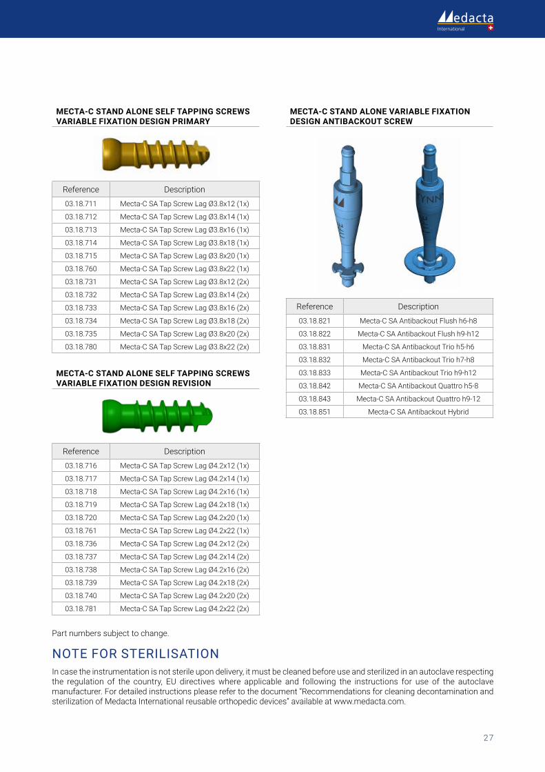
Part numbers subject to change.
NOTE FOR STERILISATIONIn case the instrumentation is not sterile upon delivery, it must be cleaned before use and sterilized in an autoclave respecting the regulation of the country, EU directives where applicable and following the instructions for use of the autoclave manufacturer. For detailed instructions please refer to the document “Recommendations for cleaning decontamination and sterilization of Medacta International reusable orthopedic devices” available at www.medacta.com.
MECTA-C STAND ALONE SELF TAPPING SCREWS VARIABLE FIXATION DESIGN PRIMARY
Reference Description
03.18.711 Mecta-C SA Tap Screw Lag Ø3.8x12 (1x)
03.18.712 Mecta-C SA Tap Screw Lag Ø3.8x14 (1x)
03.18.713 Mecta-C SA Tap Screw Lag Ø3.8x16 (1x)
03.18.714 Mecta-C SA Tap Screw Lag Ø3.8x18 (1x)
03.18.715 Mecta-C SA Tap Screw Lag Ø3.8x20 (1x)
03.18.760 Mecta-C SA Tap Screw Lag Ø3.8x22 (1x)
03.18.731 Mecta-C SA Tap Screw Lag Ø3.8x12 (2x)
03.18.732 Mecta-C SA Tap Screw Lag Ø3.8x14 (2x)
03.18.733 Mecta-C SA Tap Screw Lag Ø3.8x16 (2x)
03.18.734 Mecta-C SA Tap Screw Lag Ø3.8x18 (2x)
03.18.735 Mecta-C SA Tap Screw Lag Ø3.8x20 (2x)
03.18.780 Mecta-C SA Tap Screw Lag Ø3.8x22 (2x)
MECTA-C STAND ALONE SELF TAPPING SCREWS VARIABLE FIXATION DESIGN REVISION
Reference Description
03.18.716 Mecta-C SA Tap Screw Lag Ø4.2x12 (1x)
03.18.717 Mecta-C SA Tap Screw Lag Ø4.2x14 (1x)
03.18.718 Mecta-C SA Tap Screw Lag Ø4.2x16 (1x)
03.18.719 Mecta-C SA Tap Screw Lag Ø4.2x18 (1x)
03.18.720 Mecta-C SA Tap Screw Lag Ø4.2x20 (1x)
03.18.761 Mecta-C SA Tap Screw Lag Ø4.2x22 (1x)
03.18.736 Mecta-C SA Tap Screw Lag Ø4.2x12 (2x)
03.18.737 Mecta-C SA Tap Screw Lag Ø4.2x14 (2x)
03.18.738 Mecta-C SA Tap Screw Lag Ø4.2x16 (2x)
03.18.739 Mecta-C SA Tap Screw Lag Ø4.2x18 (2x)
03.18.740 Mecta-C SA Tap Screw Lag Ø4.2x20 (2x)
03.18.781 Mecta-C SA Tap Screw Lag Ø4.2x22 (2x)
MECTA-C STAND ALONE VARIABLE FIXATION DESIGN ANTIBACKOUT SCREW
Reference Description
03.18.821 Mecta-C SA Antibackout Flush h6-h8
03.18.822 Mecta-C SA Antibackout Flush h9-h12
03.18.831 Mecta-C SA Antibackout Trio h5-h6
03.18.832 Mecta-C SA Antibackout Trio h7-h8
03.18.833 Mecta-C SA Antibackout Trio h9-h12
03.18.842 Mecta-C SA Antibackout Quattro h5-8
03.18.843 Mecta-C SA Antibackout Quattro h9-12
03.18.851 Mecta-C SA Antibackout Hybrid

Mecta-C® Stand AloneSurgical Technique
ref: 99.44csa.12rev. 03
Last update: March 2021 0476
Medacta International SAStrada Regina - 6874 Castel San Pietro - SwitzerlandPhone +41 91 696 60 60 - Fax +41 91 696 60 [email protected]
Find your local dealer at: medacta.com/locations
This document is not intended for the US market. All trademarks are property of their respective owners and are registered at least in Switzerland.Please verify approval of the devices described in this document with your local Medacta representative.