Embed Size (px)
Citation preview

International Research Journal of Engineering and Technology (IRJET) e-ISSN: 2395-0056
Volume: 08 Issue: 01 | Jan 2021 www.irjet.net p-ISSN: 2395-0072
© 2021, IRJET | Impact Factor value: 7.529 | ISO 9001:2008 Certified Journal | Page 360
Anti-Dive and Anti-Squat Suspension Geometry
Prof. Siddhesh Lad1, Vikas Tiwari2, Sunny Mhatre3, Ganesh Salgaonkar4, Shubham Padekar,
Jatin Sawant5
1Professor, Automobile Department, Saraswati College of engineering, Navi Mumbai, Maharashtra, India 2,3,4,5,6 students, Automobile Department, Saraswati College of engineering, Navi Mumbai, Maharashtra, India
--------------------------------------------------------------------***--------------------------------------------------------------------Abstract - This paper presents a review of recent research that has been carried out on the Suspension system of a Formula Student car. In any formula student race car, racing cars, baja cars, or any given car suspension plays an important role. Suspension is primarily used to prevent the driver from sudden road shocks. It’s also used to control the longitudinal load transfer, lateral load transfer and giving the exact amount of feedback needed by the driver. While designing a suspension system few factors need to be considered such as C.G, Roll-centre, camber, toe-in, toe-out. Handling characteristics is also improved by optimizing suspension system. The modeling of suspension geometry can be carried out in Lotus shark software to carry out validation purpose and to check whether the desired suspension geometry is achieved or not.
Key Words: Suspension, Lateral load transfer, C.G, Roll-centre, Handling
1. INTRODUCTION
Formula SAE is a student design competition organized by SAE International (also known as Society of Automotive Engineer, SAE). This competition challenges students to conceive, design, fabricate the cars and compete with other student formula teams. The competition has dynamic events like brake test, skidpad, endurance. The suspension is arguably the most important part of a vehicle, this is especially true for a racecar. Without a good suspension design the performance of a racecar will suffer dramatically. The goal this time while designing our car is to have Anti-dive and Ani-squat geometry. This anti-geometry is referred to in the form of geometry at the front and the geometry at the rear of the car. The basic fundamental of this geometry is to reduce the pitching moment of the car by altering the loading conditions. When the car is in steady state acceleration there is longitudinal weight transfer at the rear (squat moment) and when the car is decelerating or braking there is longitudinal weight transfer at the front (dive moment). In this geometry all the forces occurring due to braking and deceleration acts through the centre of gravity i.e., the rotation of the car will be around COG. It affects the suspension deflection when the brakes are applied, therefore causing the lowering of the front end of the car.
2. PROBLEM STATMENT
In Formula SAE competition, along-with performance design itself also plays a huge role. The concept of Anti-dive and Anti-squat is to enhance the performance of the car by altering the forces acting on the car during the competition. The design itself doesn’t created a huge difference, when comparing the weight of the system to the simple suspension system, so this will be important in aspect of judging and scoring. Suspension system is considered as the most crucial part in vehicle, optimizing the suspension to alter the loading forces as required will benefit in overall improved performance of the race car which will eventually lead to a competition winning car. The main purpose of this design is to manufacture a car which will be better in handling and stability which will certainly improve the performance of the car, as well as this design process will help future team members to reiterate and optimized the
design.
■ Anti-dive & anti squat geometry is used to control the amount of load going through the springs and the pitch attitude of the car.
■ Anti-geometry is an understanding of how a car moves and rotates under acceleration or braking conditions must be achieved.
■ All forces acting upon a car act through the center
of gravity.
■ The center of gravity is therefore the center of rotation for any acceleration or braking inputs.
FIG: CAD OF SUSPENSION SYSTEM

International Research Journal of Engineering and Technology (IRJET) e-ISSN: 2395-0056
Volume: 08 Issue: 01 | Jan 2021 www.irjet.net p-ISSN: 2395-0072
© 2021, IRJET | Impact Factor value: 7.529 | ISO 9001:2008 Certified Journal | Page 361
3. Design Objectives
The points we keep in mind while designing the suspension system are:
1. Cost efficient
2. Double Wishbone Adjustable Anti-dive and Anti-squat suspension geometry
3. Adjustable camber angle with Camber plates
4. Less weight
5. High strength
6. Adjustable stiffness Anti-Roll bar
7. Pull and Push suspension and specifically designed to meet the operating conditions of FSAE Race Car.
4. SELECTION OF DIFFERENT PARTS
4.1. TIRE SELECTION
Tire selection plays a most important role in vehicle. After selecting tire, bearing selection, hub design, suspension points, upright design are made. What should be kept in mind while selecting tire? 1. Contact patch should be optimum, so to get more traction 2. Diameter of the rim 3. PCD (Pitch Circle Diameter) 4. Width of the rim 5. Tire life.
We are using HOOSIER R – 10 tires. R –
10 (rim has diameter of 10’’) is used
instead of R – 13 because,
1. Due to compact structure, the force transmission from the center can easily transmitted to the A-Arms.
2. It keeps the roll center and center of gravity close to the ground as compared to R-13
3. Load on the engine will be less as the diameter is small
4. Vehicle is close to the ground
5. Weight of R-10 is less as compared to R-13
6. Weight of every component will be less
7. Fuel efficiency will be more as compared to R-13
4.2. SUSPENSION POINT SELECTION
The first point to find in suspension is Lower Ball joint (LBJ). Let consider X-axis w.r.t solid works first there is hub, then rotor and caliper by considering all their thickness & bearing thickness and placing the point as close to the centre as possible, as all forces pass through the centre. We fixed the X-axis coordinate of LBJ. Now let us consider Y-axis w.r.t solid works first we take inner diameter of rim, outer diameter of bearing, diameter of rotor and then very small distance. Placing the LBJ close to the centre we fixed the point of LBJ on Y-axis.
Finally considering Z-axis w.r.t solid works we are placing the Z-axis point at the center line of the tire as all forces passes through the center. We fixed all the 3 points on different axis. This is done by making the design of hub, taking information and CAD of rotor and caliper and selecting bearing. Similarly, we have to find UBJ. For finding the points on chassis, we have to first need the line diagram of front hoop, after that we have assumed the lower A-Arm to be parallel to the ground and for upper A-Arm we have done iteration on the angle views from the front view. The lower A-Arm is kept parallel because: -
1. To ease the design
2. To bring C.G down
3. To keep Instantaneous Centre (I.C) moderate
4. To lower the vehicle and bring it close to ground
5. To bring Roll center down
FIG: SIDE VIEW By this view, we can see that the rear A-Arms has more angle made with the horizontal than the front. This angle is decided by using Anti-dive and Anti-squat suspension geometry. This angle helps to control the pitch movement. With this angle the pitch center is coming out to be close to the center of gravity

International Research Journal of Engineering and Technology (IRJET) e-ISSN: 2395-0056
Volume: 08 Issue: 01 | Jan 2021 www.irjet.net p-ISSN: 2395-0072
© 2021, IRJET | Impact Factor value: 7.529 | ISO 9001:2008 Certified Journal | Page 362
4.3 BEARING SELECTION
By selecting the bearing, we are getting the outer diameter of the hub and inner diameter of the upright.
FOR FRONT
Radial load only:
Fe = V*R
V = 1 inner ring
N = 100*10^6
Reliability = 90%
Kr = 1 & Ka = 1
Rx = 2613.741 + 27.74= 2641.481N
Ry = 1136.409 N
R= (Rx2+ Ry2)1/2 = (2641.4812+ 1136.4092)1/2 = 2875.560343 N
Fe = V x R = 1 x 2875.560343 = 2875.560 N L = 100
a Creq = Fe(L)1/a in
N
Ball Bearing 3 13347.16878 Roller Bearing 10/3 11447.81192 From above values, We selected SKF 7007 angular contact ball bearing with OD = 62 mm, ID = 35 mm and width =14mm. For Rear
Radial load only
Fe = V*R
V = 1 inner ring
N = 100*10^6
Reliability = 90%
Kr = 1 & Ka = 1 Rx = 3263.09 – 21.281 = 3241.728 N Ry = 1418.7 N R = (Rx2 + Ry2)1/2 = (3241.7282 + 1418.72)1/2 = 3538.57458 N
Fe = V x R = 1 x 3538.5745 = 3538.5745 N L = 100
a Creq = Fe(L)1/a in N
Ball Bearing 3 1664.355804
Roller Bearing 10/3 1427.51147
From above values We selected SKF 71910 angular contact ball bearing with OD = 72 mm, ID = 50 mm and width = 12mm
5. FORCES ACTING ON TIRES
Wheelbase (L) 65’’ 1651 mm
Trackwidth (t) 47’’ 1193.8 mm
CG height 13.8’’ 350 mm
Total weight (m) 595.248 lb 270 kg
% front weight 40 40
% rear weight 60 60
B 39’’ 990.6 mm
C 26’’ 660.4 mm
Wheel radius (r) 3.1496’’ 80 mm
µ 2.3 2.3
Longitudinal 2648.7 N 2648.7 N
Lateral 4820.634 N 4820.634 N
Braking 16.677 N 16.677 N
Roll angle 30 30
Front weight (mf) 238.099 lb 108 kg Rear weight (mr) 357.1489 lb 162 kg
Grade angle 0.04 0.04
Rolling coefficient
(fr)
0.015 0.015
Longitudinal
acceleration
9.81 m/s2 9.81 m/s2
Lateral acceleration 17.8542
m/s2
17.8542 m/s2
All the forces calculated are the maximum forces on the tires at different condition.
Static Fz = W x b
L

International Research Journal of Engineering and Technology (IRJET) e-ISSN: 2395-0056
Volume: 08 Issue: 01 | Jan 2021 www.irjet.net p-ISSN: 2395-0072
© 2021, IRJET | Impact Factor value: 7.529 | ISO 9001:2008 Certified Journal | Page 363
Front right N
Fx 0
Fy 0
Fz -541.53
Front left N
Fx 0
Fy 0
Fz -541.53
Rear right N
Fx 0
Fy 0
Fz -806.39
Rear left N
Fx 0
Fy 0
Fz -806.39
Linear acceleration and tractive force on rear wheels
only with no lateral force.
Fx = (W x b x µ)
(L – (h x µ))
Fy = 0
Fz = Wfs + W x ax x h
L
Front left N
Fx 0
Fy 0
Fz -246.7555
Front right N
Fx 0
Fy 0
Fz -246.7555
Rear left N
Fx -2496.215
Fy 0
Fz -836.30
Rear right N
Fx -2496.215
Fy 0
Fz -836.30
Steady State Cornering Mɸf = W x h1 x ay + Wf x hf x ay =
(270 x 9.81 x 0.27785 x 1.82) + 252.6976 (Kɸf + Kɸr) –
(W x h1) [41329.93306 – (270 x 9.81 x 0.22785)] = 252.696 Nm
Mɸr = W x h1 x ay + Wr x hr x ay =
(270 x 9.81 x 0.27785 x 1.82) + 379.04645 (Kɸf + Kɸr)
– (W x h1) [41329.93306 – (270 x 9.81 x 0.22785)] = 379.04645 Nm
Corning while accelerating
Fx N
Fxfl 1054.389
Fxfr 80.684
Fxrl 3263.009
Fxrr 1802.348
Fy N
Fyfl 834.3426
Fyfr 63.8456
Fyrl 2582.034
Fyrr 1426.205
Fz N
Fzfl 458.43
Fzfr 35.08
Fzrl 1418.7
Fzrr 783.6295
Rolling Resistance While accelerating:
Fx N
Fxf 7.40
Fxr 33.0349
Corning while accelerating:
Fx N
Fxfl 6.876
Fxfr 0.526
Fxrl 21.281
Fxrr 11.75

International Research Journal of Engineering and Technology (IRJET) e-ISSN: 2395-0056
Volume: 08 Issue: 01 | Jan 2021 www.irjet.net p-ISSN: 2395-0072
© 2021, IRJET | Impact Factor value: 7.529 | ISO 9001:2008 Certified Journal | Page 364
6. MATERIAL SELECTION
The material we are using for hub,
upright, clevis, bell crank is selected as
Aluminium 7075 T6.
The material of the A-Arms, pull rod in front, push rod in rear, tie rod, third link are selected by using matrix calculation.
Then we choose AISI 1018 material of hollow tubes with OD = 14 mm and ID = 10 mm of thickness.
Sr no. Mild steel AISI 1018
Aluminium 7075 T6
1 Heavy material Light material
2 High strength Comparatively low strength for same dimension
3 Easily available Available in big market
4 Low cost Very high cost
5 Machining cost is less
Machining cost is high
7.1 ANTI-ROLL BAR (ARB)
In our vehicle we are using U type anti-roll bar. It consists of a tube and its mounts. we are using the ARB in front.
ARB stiffness front
Kɸbr = Kɸ - Kɸf – Kɸbr = 314.575 – 83.58558 - 120.48 =
110.50942 lb-ft/deg
Rear roll stiffness
Kɸr = Kɸf – Kɸsf = 83.58558 – 69.0765 = 161.212 lb-ft/deg
MR2 0.3
ARB stiffness rear Kɸbr = 14.50 lb-ft/deg
ɸ = -W x hs x ay= -(79.366 + 158.18) x 15.935 x 0.046228= 0.049 c = 2.80750 = 30
Kɸf + Kɸr – (Ws x hs)(83.58 + 161.212) – (79.366 + 158.18 x 15.9)
FIG: - ANTI-ROLL BAR (ARB)
7. SHOCKS SELECTION
The shocks selection is done on the basis of the design requirement and analysis and on the performance, cost and on the market availability.
Sr No.
Local Shocks Fox DHX RC 4
DNM Burner RCP 2
1 Low build quality
High built quality
High build
quality 2 Leakage issues No leakage
issues No
leakage issues
3 No compression and rebound adjustments
Compression and rebound adjustments
Compression and
rebound adjustment
s 4 Easily
available at local
dealers
Needs to import
Needs to import
5 Low cost High cost Average cost
6 less durable More durable
More durable
By comparing all the parameters and also by using calculation DNM Burner RCP 2 was finalized. Calculation is
given below.

International Research Journal of Engineering and Technology (IRJET) e-ISSN: 2395-0056
Volume: 08 Issue: 01 | Jan 2021 www.irjet.net p-ISSN: 2395-0072
© 2021, IRJET | Impact Factor value: 7.529 | ISO 9001:2008 Certified Journal | Page 365
FIG: DNM BURNER RCP 2
7.1 RIDE RATE & ROLL RATE
RIDE RATE The sprung mass resting on the suspension and tire springs is capable of motion in the vertical direction. The effective stiffness of the suspension and tire springs in
series is called the "ride rate" determined as follows:
RR = Ks Kt
Ks + Kt
where:
RR = Ride rate
Ks = Suspension stiffness
Kt = Tire stiffness
The ride rate for our vehicle is fined using the following calculation:
Unsprung mass
Component Front (kg) Rear (kg) Upright 0.45 x 2 0.5 x 2
Wheel assembly 5.55 x 2 5.55 x 2 A-arm 0.3 x 2 0.3 x 2
Disc 0.5 x 2 0.5 x 2 Hub 0.45 x 2 0.5 x 2
Upright bearing 0.25 x 2 0.3 x 2 Clevis 0.2 x 2 0.3 x 2
Caliper 0.9 x 2 0.8 x 2 A-arm 0.25 x 2 0.25 x 2 Total 180 185
Front
Total Front unsprung mass = 36.5 kg
Front weight =108 kg
Front unsprung mass =36 kg
Front sprung weight/ mass =72 kg
Front corner sprung mass (Wsf)=36 kg
Wsf = 36 kg = 79.366 lb
By performing different iteration, we finalized the following result:
wn = 2.3 Hz
Front ride rate, Krf = 4π2 wn2 Wsf = 42.896 lb/in
386.4
Kt =1198 lb/in
Wheel centre rate, Kwf = Krf x Kt = 44.488 lb/in
Kt - Krf
Damping ratio
Range – 0.2, 0.3 & 0.4
0.2
Ksf = Kwf = 44.488 = 1112.2 lb/in
LR 2 0.22 0.3
Ksf = Kwf = 44.488 = 494.3 lb/in
LR 2 0.32
0.4
Ksf = Kwf = 44.488 = 278.05 lb/in
LRf2 0.42
Rear
Rear weight = 162 kg
Rear unsprung mass = 18.5 kg
Rear sprung mass = 143.5 kg Rear corner sprung mass (Wsr) = 71.75 kg = 158.18 lb
By performing different iteration, we finalized the following result: wn = 2.15 Hz
Rear ride rate, Krr = 4π2 wn2 Wsr = 47.846 lb/in
386.4
Kt =1198 lb/in
Wheel centre rate, Kwr = Krr x Kt = 49.8365 lb/in
Kt – Krr

International Research Journal of Engineering and Technology (IRJET) e-ISSN: 2395-0056
Volume: 08 Issue: 01 | Jan 2021 www.irjet.net p-ISSN: 2395-0072
© 2021, IRJET | Impact Factor value: 7.529 | ISO 9001:2008 Certified Journal | Page 366
Damping ratio
Range – 0.2, 0.3 & 0.4
0.2
Ksr = Kwr = 49.8365 = 1245.913 lb/in
LR 20.22
0.3
Ksr = Kwr = 49.8365 = 553.739 lb/in
LR 20.32
0.4
Ksr = Kwr = 49.8365 = 311.4782 lb/in
LR 20.42
For above all cases and calculations we decided to choose DNM Burner RCP 2 for both front and rear with a Stiffness which has spring rate, Ks = 550 lb/in by giving,
Front rear
Natural undamped frequency (wn) in Hz 2.3 2.15
Left ride rate (Kr) in lb/in 42.896 75
Left tire spring rate (Kt) in lb/in 1198 1198
Left wheel centre rate (Kw) in lb/in 44.488 80
Damping ratio (LR) 0.3 0.4
Left spring rate (Ks) in lb/in 494.3 497.42
Total ride rate in lb/in 85.792 150
8. ASSEMBLY OF SUSPENSION SYSTEM
The parts are: 1. Upright
2. Hub
3. Wheel / Rim
4. Clevis
5. Shim
6. Bearings
7. A-Arm end
8. A-Arm tube
9. Nut
10. Rod end
11. Billet
12. Shock Absorber
13. Rear Upper Bulkhead
14. Bell crank / Rocker
15. Rear Upper Bulkhead mounts
The parts we are using with Aluminium 7075 T6 are:
1. Hub
2. Upright
3. Bell crank
4. Clevis
The parts we are using with Mild Steel AISI 1018 are:
1. A-Arm end
2. A-Arm tube
3. ARB mounts
4. ARB tube
5. Billet
The parts we are using with Stainless Steel 316 is Shims 9. ANALYSIS OF SUSPENSION COMPONENTS
FIG: STRESS ANALYSIS OF BELL CRANK
FIG: STRAIN ANALYSIS OF BELL CRANK

International Research Journal of Engineering and Technology (IRJET) e-ISSN: 2395-0056
Volume: 08 Issue: 01 | Jan 2021 www.irjet.net p-ISSN: 2395-0072
© 2021, IRJET | Impact Factor value: 7.529 | ISO 9001:2008 Certified Journal | Page 367
FIG: DISPLACEMENT OF FRONT BELL CRANK
FIG: FOS OF FRONT BELL CRANK
FIG: STRESS ANALYSIS OF REAR BELL CRANK
FIG: STRAIN ANALYSIS OF REAR BELL CRANK
FIG: DISPLACEMENT OF REAR BELL CRANK
FIG: FOS OF REAR BELL CRANK
FIG: STRESS ANALYSIS OF FRONT A-ARM
FIG: STRAIN ANALYSIS OF FRONT A-ARM

International Research Journal of Engineering and Technology (IRJET) e-ISSN: 2395-0056
Volume: 08 Issue: 01 | Jan 2021 www.irjet.net p-ISSN: 2395-0072
© 2021, IRJET | Impact Factor value: 7.529 | ISO 9001:2008 Certified Journal | Page 368
FIG: DISPLACEMENTOF FRONT A-ARM
FIG: STRESS ANALYSIS OF REAR A-ARM
FIG: STRAIN ANALYSIS OF REAR A-ARM
FIG: DISPLACEMENT OF REAR A-ARM
FIG: STRESS ANALYSIS OF FRONT HUB
FIG: STRAIN ANALYSIS OF FRONT HUB
FIG: DISPLACEMENT OF FRONT HUB
FIG: FOS OF FRONT HUB

International Research Journal of Engineering and Technology (IRJET) e-ISSN: 2395-0056
Volume: 08 Issue: 01 | Jan 2021 www.irjet.net p-ISSN: 2395-0072
© 2021, IRJET | Impact Factor value: 7.529 | ISO 9001:2008 Certified Journal | Page 369
FIG: STRESS ANALYSIS OF REAR HUB
FIG: STRAIN ANALYSIS OF REAR HUB
FIG: DISPLACEMENT OF REAR HUB
FIG: DISPLACEMENT OF REAR HUB
FIG: FOS OF REAR HUB
International Research Journal of Engineering and Technology (IRJET) e-ISSN: 2395-0056
Volume: 08 Issue: 01 | Jan 2021 www.irjet.net p-ISSN: 2395-0072
© 2021, IRJET | Impact Factor value: 7.529 | ISO 9001:2008 Certified Journal | Page 370
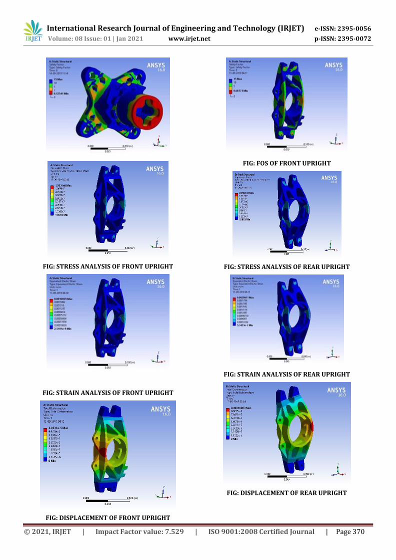
FIG: STRESS ANALYSIS OF FRONT UPRIGHT
FIG: STRAIN ANALYSIS OF FRONT UPRIGHT
FIG: DISPLACEMENT OF FRONT UPRIGHT
FIG: FOS OF FRONT UPRIGHT
FIG: STRESS ANALYSIS OF REAR UPRIGHT
FIG: STRAIN ANALYSIS OF REAR UPRIGHT
FIG: DISPLACEMENT OF REAR UPRIGHT
International Research Journal of Engineering and Technology (IRJET) e-ISSN: 2395-0056
Volume: 08 Issue: 01 | Jan 2021 www.irjet.net p-ISSN: 2395-0072
© 2021, IRJET | Impact Factor value: 7.529 | ISO 9001:2008 Certified Journal | Page 371
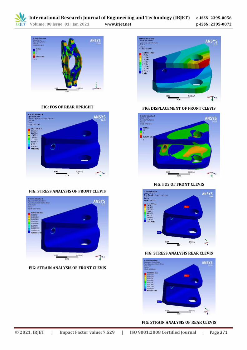
FIG: FOS OF REAR UPRIGHT
FIG: STRESS ANALYSIS OF FRONT CLEVIS
FIG: STRAIN ANALYSIS OF FRONT CLEVIS
FIG: DISPLACEMENT OF FRONT CLEVIS
FIG: FOS OF FRONT CLEVIS
FIG: STRESS ANALYSIS REAR CLEVIS
FIG: STRAIN ANALYSIS OF REAR CLEVIS

International Research Journal of Engineering and Technology (IRJET) e-ISSN: 2395-0056
Volume: 08 Issue: 01 | Jan 2021 www.irjet.net p-ISSN: 2395-0072
© 2021, IRJET | Impact Factor value: 7.529 | ISO 9001:2008 Certified Journal | Page 372
FIG: DISPLACEMENT OF REAR CLEVIS
FIG: FOS OF REAR CLEVIS
10. CONCLUSION
Lots of conclusions can be made to this study. Increasing vehicle speed over a barrier caused, greater inertial imbalance, thus reducing the effect of anti-dive and anti-squat features which are designed essentially for normal pitch plane dynamics with smaller suspension vertical travel. This has been shown in the results of negotiating bumps at progressively higher forward speeds.
ACKNOWLEDGEMENT
I would like to express my sincere gratitude to Prof. Siddhesh Lad, Automobile Engineering Department. Saraswati College of Engineering, Kharghar for providing their invaluable guidance, comments and suggestions.
REFERENCES
[1] Race Car Vehicle Dynamics Milliken Milliken
[2] Fundamentals of Vehicle Dynamics: Thomas D. Gillespie
[3] Design of a Suspension for a Formula Student Race Car
[4] VDHS-12 Vehicle Dynamics Design Process | Suspension
[5] Design, Analysis and Simulation of Double Wishbone ... - irjet