Embed Size (px)
Citation preview

Anybus® Serial Server
USER MANUALHMSI-27-200 2.1 ENGLISH

Important User InformationLiabilityEvery care has been taken in the preparation of this document. Please inform HMS Industrial Networks AB of anyinaccuracies or omissions. The data and illustrations found in this document are not binding. We, HMS IndustrialNetworks AB, reserve the right to modify our products in line with our policy of continuous product development.The information in this document is subject to change without notice and should not be considered as a commit-ment by HMS Industrial Networks AB. HMS Industrial Networks AB assumes no responsibility for any errors thatmay appear in this document.
There are many applications of this product. Those responsible for the use of this device must ensure that all thenecessary steps have been taken to verify that the applications meet all performance and safety requirements in-cluding any applicable laws, regulations, codes, and standards.
HMS Industrial Networks AB will under no circumstances assume liability or responsibility for any problems thatmay arise as a result from the use of undocumented features, timing, or functional side effects found outside thedocumented scope of this product. The effects caused by any direct or indirect use of such aspects of the productare undefined, and may include e.g. compatibility issues and stability issues.
The examples and illustrations in this document are included solely for illustrative purposes. Because of the manyvariables and requirements associated with any particular implementation, HMS Industrial Networks AB cannot as-sume responsibility for actual use based on these examples and illustrations.
Intellectual Property RightsHMS Industrial Networks AB has intellectual property rights relating to technology embodied in the product de-scribed in this document. These intellectual property rights may include patents and pending patent applications inthe USA and other countries.
Trademark AcknowledgementsAnybus® is a registered trademark of HMS Industrial Networks AB. All other trademarks are the property of their re-spective holders.
Copyright © 2016 HMS Industrial Networks AB. All rights reserved.Anybus® Serial Server User Manual
HMSI-27-200 2.1
Anybus® Serial Server User Manual HMSI-27-200 2.1
Table of Contents Page
1 Preface ............................................................................................................................... 31.1 About This Document.....................................................................................................31.2 Document history...........................................................................................................31.3 Conventions ..................................................................................................................41.4 Terminology...................................................................................................................4
2 Introduction ...................................................................................................................... 5
3 Installation ........................................................................................................................ 63.1 Mounting on DIN Rail .....................................................................................................63.2 MAC ID and Default IP Address ......................................................................................63.3 Connections ..................................................................................................................73.4 LED Indicators ...............................................................................................................8
4 Configuration ................................................................................................................... 94.1 IP Configuration.............................................................................................................94.2 Installing the Windows Driver (Serial/IP) ........................................................................124.3 Configuration Interface .................................................................................................12
A Technical Data................................................................................................................ 15
B Regulatory Compliance............................................................................................... 16

This page intentionally left blank

Preface 3 (18)
1 Preface1.1 About This Document
This manual describes how to install and configure Anybus Serial Server.
For additional related documentation and file downloads, please visit the Anybus support web-site at www.anybus.com/support.
1.2 Document historySummary of recent changesChange Where (section no.)Updated CE/UL compliance information B
Revision listVersion Date Author Description1.00 030302 JOAK First released version.1.10 051101 HACA Update for Modbus support, etc.
1.20 060630 MASA Update to new design structure.
1.20:1 061117 PeP Updated layout + misc. minor changes.
1.40:1 080403 PeP Updated to match new version of product.
1.50 130923 SDa Added UL specific information. General update.
2.0 Oct 2015 ThN Minor corrections, updated screenshotsNew layout and structure
2.1 April 2016 ThN Updated compliance informationUpdated layout
Anybus® Serial Server User Manual HMSI-27-200 2.1
Preface 4 (18)
1.3 ConventionsUnordered (bulleted) lists are used for:
• Itemized information
• Instructions that can be carried out in any order
Ordered (numbered or alphabetized) lists are used for instructions that must be carried out insequence:
1. First do this,
2. Then open this dialog, and
a. set this option...
b. ...and then this one.
Bold typeface indicates interactive parts such as connectors and switches on the hardware, ormenus and buttons in a graphical user interface.
Monospaced text is used to indicate program code and otherkinds of data input/output such as configuration scripts.
This is a cross-reference within this document: Conventions, p. 4
This is an external link (URL): www.hms-networks.com
This is additional information which may facilitate installation and/or operation.
This instruction must be followed to avoid a risk of reduced functionality and/ordamage to the equipment, or to avoid a network security risk.
CautionThis instruction must be followed to avoid a risk of personal injury.
WARNINGThis instruction must be followed to avoid a risk of death or serious injury.
1.4 TerminologyIn this document the TIA-232/485 serial communication standards are referred to asRS-232/485 when describing hardware, and as EIA-232/485 in the software interface.
Anybus® Serial Server User Manual HMSI-27-200 2.1

Introduction 5 (18)
2 IntroductionA serial server is a device which forwards data between a serial port and an Ethernet network.It can be used to connect serial devices to a LAN or the Internet with no hardware modifications.When also using a special software driver in a personal computer, the serial server can be usedas a remote serial port.
Computer applications designed to access devices on a standard serial port can access the re-mote serial server with no software modifications required. The combination of the LAN/Internetnetwork, the serial server and the driver can be thought of as an extended “virtual” serial cable.
RS-485
RS-232
Anybus Serial Server
Computer with Serial/IP software
Serial Device
Serial Device
Serial Device
Serial Device Serial Device
Ethernet
Fig. 1 Overview
The Anybus Serial Server connects serial devices to Ethernet networks using the IP protocolfamily. Examples of supported types of serial devices are:
• Scanners
• Printers
• PLCs
• Data collection devices
• Telecommunications equipment
• Data display devices
• Security alarms and access control devices
• Hand-held instruments
• Modems
Anybus® Serial Server User Manual HMSI-27-200 2.1
Installation 6 (18)
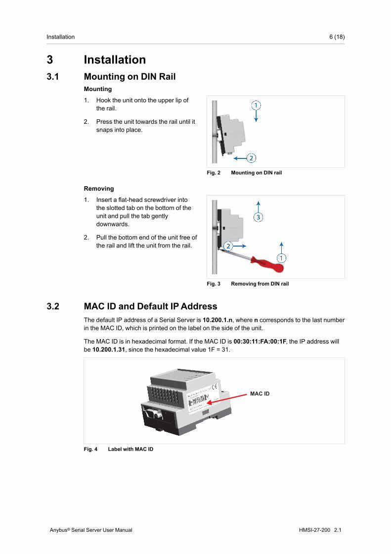
3 Installation3.1 Mounting on DIN Rail
Mounting
Fig. 2 Mounting on DIN rail
1. Hook the unit onto the upper lip ofthe rail.
2. Press the unit towards the rail until itsnaps into place.
Removing
Fig. 3 Removing from DIN rail
1. Insert a flat-head screwdriver intothe slotted tab on the bottom of theunit and pull the tab gentlydownwards.
2. Pull the bottom end of the unit free ofthe rail and lift the unit from the rail.
3.2 MAC ID and Default IPAddressThe default IP address of a Serial Server is 10.200.1.n, where n corresponds to the last numberin the MAC ID, which is printed on the label on the side of the unit.
The MAC ID is in hexadecimal format. If the MAC ID is 00:30:11:FA:00:1F, the IP address willbe 10.200.1.31, since the hexadecimal value 1F = 31.
MAC ID
Fig. 4 Label with MAC ID
Anybus® Serial Server User Manual HMSI-27-200 2.1
Installation 7 (18)
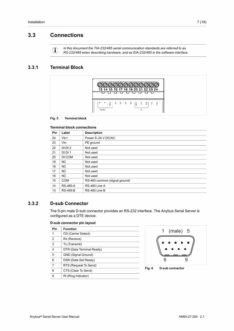
3.3 Connections
In this document the TIA-232/485 serial communication standards are referred to asRS-232/485 when describing hardware, and as EIA-232/485 in the software interface.
3.3.1 Terminal Block
Fig. 5 Terminal block
Terminal block connectionsPin Label Description24 Vin+ Power 9–24 V DC/AC23 Vin- PE ground
22 DI:DI 2 Not used21 DI:DI 1 Not used20 DI:COM Not used19 NC Not used18 NC Not used17 NC Not used16 NC Not used15 COM RS-485 common (signal ground)
14 RS-485:A RS-485 Line A13 RS-485:B RS-485 Line B
3.3.2 D-sub ConnectorThe 9-pin male D-sub connector provides an RS-232 interface. The Anybus Serial Server isconfigured as a DTE device.
6 9
51 (male)
Fig. 6 D-sub connector
D-sub connector pin layoutPin Function1 CD (Carrier Detect)
2 Rx (Receive)
3 Tx (Transmit)
4 DTR (Data Terminal Ready)
5 GND (Signal Ground)
6 DSR (Data Set Ready)
7 RTS (Request To Send)
8 CTS (Clear To Send)
9 RI (Ring Indicator)
Anybus® Serial Server User Manual HMSI-27-200 2.1

Installation 8 (18)
3.3.3 Ethernet ConnectorThe RJ-45 socket provides a 10/100 Mbps Ethernet network connection.
1 8
Fig. 7 Ethernet connector
Ethernet connector pin layoutPin Function1 TD+2 TD-3 RD+4, 5, 7, 8 Termination6 RD-
3.4 LED Indicators
Fig. 8 LED Indicators
LED Indication Meaning
Status
OFF No power
Green System is operating normally
Orange System is starting up
Red Hardware faultFlashing red Error during initialization
Serial Link
Flashing green Receiving serial packet (on either port)
Flashing red Transmitting serial packet (on either port)
Orange System is starting up
ActivityFlashing green Receiving Ethernet packet
Flashing red Ethernet collision
LinkGreen 10 Mbps Ethernet network detected
Orange 100 Mbps Ethernet network detected
Anybus® Serial Server User Manual HMSI-27-200 2.1

Configuration 9 (18)
4 Configuration4.1 IP Configuration4.1.1 Installing the IPconfig Utility
IPconfig is a Windows-based tool used for TCP/IP network configuration of a HMS devices. Thetool will detect all connected devices and allow configuration of their IP address, netmask, de-fault gateway, DNS and hostname.
1. Download IPconfig from www.anybus.com/support.
2. Extract the contents of the zip archive in a folder on your computer and double-click theexecutable file to run the installer.
4.1.2 Scanning for Connected DevicesMake sure that the devices to be configured are connected on the same Ethernet subnet as thecomputer running IPconfig. Use standard Ethernet cables.
When IPconfig utility started it will scan the available local networks. All detected devices will bepresented in a list in the main window. To refresh the list, click on Scan.
Fig. 9 IPconfig main window
IP IP address of the device
SN Subnet mask
GW Default gateway
DHCP Automatically managed IP configuration
Version Firmware version
Type Product name
MAC Ethernet MAC address (System ID)
Anybus® Serial Server User Manual HMSI-27-200 2.1
Configuration 10 (18)
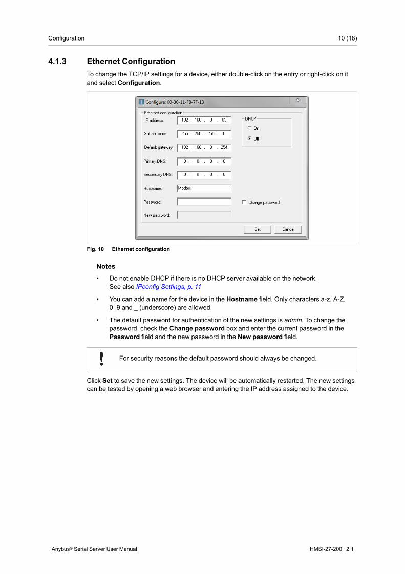
4.1.3 Ethernet ConfigurationTo change the TCP/IP settings for a device, either double-click on the entry or right-click on itand select Configuration.
Fig. 10 Ethernet configuration
Notes• Do not enable DHCP if there is no DHCP server available on the network.
See also IPconfig Settings, p. 11
• You can add a name for the device in the Hostname field. Only characters a-z, A-Z,0–9 and _ (underscore) are allowed.
• The default password for authentication of the new settings is admin. To change thepassword, check the Change password box and enter the current password in thePassword field and the new password in the New password field.
For security reasons the default password should always be changed.
Click Set to save the new settings. The device will be automatically restarted. The new settingscan be tested by opening a web browser and entering the IP address assigned to the device.
Anybus® Serial Server User Manual HMSI-27-200 2.1

Configuration 11 (18)
4.1.4 IPconfig SettingsAdditional settings for IPconfig can be accessed by clicking on Settings.
Fig. 11 IPconfig settings
Network Interface Check this option to select a specific network interface to use when scanning fordevices on a computer with multiple interfaces.
Internal DHCP Server If a device has been set to use DHCP but there is no DHCP server on thenetwork, the device may no longer be detected in a scan. To recover the device,an internal DHCP server in IPconfig can be activated.
Click the checkbox to enable the option, then click OK to close the window.IPconfig will automatically refresh, and the missing device should now bedetected. Select the device and change its configuration to use manualaddressing instead of DHCP.
Disable the internal DHCP server after the device has been recovered.
Anybus® Serial Server User Manual HMSI-27-200 2.1
Configuration 12 (18)
4.2 Installing the Windows Driver (Serial/IP)To use Anybus Serial Server, the Serial/IP driver software must be installed on a computer. Thedriver can be downloaded from www.anybus.com/support.
For instructions on how to install and configure the driver, please refer to the Serial/IP softwareQuick Start Guide which is also available on the support website.
4.3 Configuration Interface4.3.1 Logging in
Open a web browser and enter the IP address for the Serial Server in the address field.
Log in with username admin and the default password admin. You can (and should) changethe password once you are logged in. See Admin , p. 14.
If you cannot log in using the default username and password, check that Caps Lock is not en-abled on your keyboard.
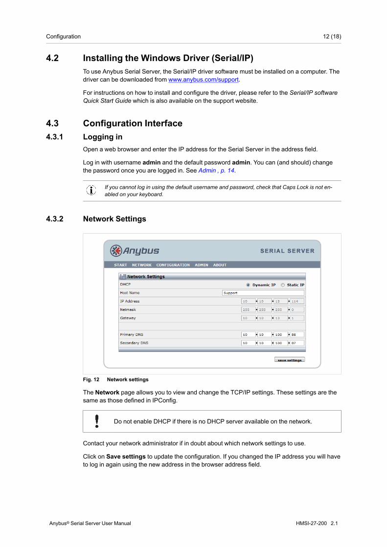
4.3.2 Network Settings
Fig. 12 Network settings
The Network page allows you to view and change the TCP/IP settings. These settings are thesame as those defined in IPConfig.
Do not enable DHCP if there is no DHCP server available on the network.
Contact your network administrator if in doubt about which network settings to use.
Click on Save settings to update the configuration. If you changed the IP address you will haveto log in again using the new address in the browser address field.
Anybus® Serial Server User Manual HMSI-27-200 2.1

Configuration 13 (18)
4.3.3 Serial Port Settings
Fig. 13 Serial port settings
The Configuration page contains settings for each of the two serial ports.
In this document the TIA-232/485 serial communication standards are referred to asRS-232/485 when describing hardware, and as EIA-232/485 in the software interface.
Serial Port Settings
Serial Port Number The port number that the Serial Server listen on, used when connecting from theSerial/IP driver, telnet, or other applications that connect to a socket port. Thedefault port numbers are 2000 for EIA-232 and 2001 for EIA-485.
Modbus Mode Controls fragmentation of received messages on the serial port. When set to On,the low level serial driver will wait 3.5 characters (standard Modbus messagebreak time) before forwarding the received characters.
Transmission in a single TCP/IP packet prevents fragmentation on the receivingside. The 3.5 char time is calculated from the current baud rate. When set to Off,the time can still be selected in milliseconds (see below).
Silent Time The time in milliseconds to wait before forwarding the received characters to theapplication in the Serial Server. A value of 0 disables the feature. If so, charactersreceived during approximately 10 ms will be sent in each TCP/IP packet. Thismay mean less delay for each received byte, but more TCP/IP overhead andpossible fragmentation of the serial packet.
Manual Serial Settings Locks the settings on the serial port. This is useful when (for example) connectingto an application that does not perform setup of the remote serial port.
If the application does not perform setup of the serial port it defaults to 19200 bps,8 data bits, no parity, 1 stop bit.
The Serial Port Number must match the value entered in the Serial/IP Driver configuration.
Anybus® Serial Server User Manual HMSI-27-200 2.1
Configuration 14 (18)
Manual Serial Settings
Baudrate Sets the communication baud rate on the serial port.
Character Format Sets the the number of data bits, parity, and stop bits.
Flow Control (EIA-232) Specifies flow control to be handled by the UART. If enabled, transmit isautomatically stopped/continued when the serial buffer is full/available.
NONE = UART flow control is disabled.
CTS/RTS = The two UARTs involved use two dedicated wires in the serial cableto control the flow.
The Serial Server uses RTS to transmit and gets CTS back when it is clear tosend. Be sure to use a serial cable with these wires connected.
XON/XOFF = The remote UARTshould send characters to signal its buffer state.
Modem Control Lines(EIA-232)
On = The modem control lines will be taken into account (DCD, DTR).
Off = The modem control line states will be ignored.
Click on Save settings to update the configuration. The next view will prompt you to clickReboot to restart the Serial Server.
After rebooting the Serial Server, wait for about 20 seconds then click on Start in the main menuto return to the start page.
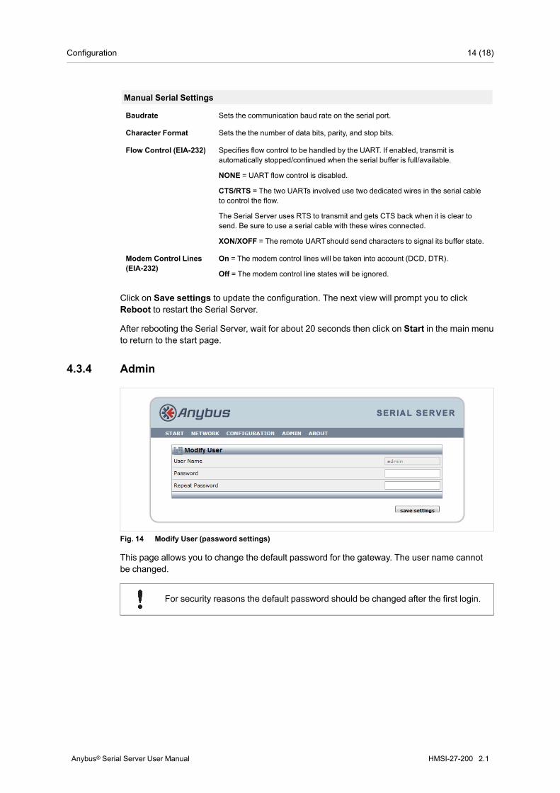
4.3.4 Admin
Fig. 14 Modify User (password settings)
This page allows you to change the default password for the gateway. The user name cannotbe changed.
For security reasons the default password should be changed after the first login.
Anybus® Serial Server User Manual HMSI-27-200 2.1

Appendix A: Technical Data 15 (18)
A Technical DataTechnical SpecificationsModel name Anybus Serial ServerOrder code AB7701Ethernet 10/100 Mbit/sSerial Interfaces EIA-232 with full modem control (RTS, CTS, DCD,
DTR, DSR, RI)EIA-485
Protocols Modbus RTU, ASCII, TCPBaud rates 300–115200 bps
Mounting DIN rail (EN 50022)
Housing Grey plastic (LEXAN 940) Self-extinguishing accord-ing to UL94–V0
Dimensions (W x D x H) 90 x 70 x 58 mm
Operating temperature -40 to +65 °C
Storage temperature -40 to +85 °C
Humidity range 5–95 % RH, non-condensing
Housing class IP20
Power supply 9–24 V DC or AC, SELV
Power consumption 2.0 W
Certifications CE, CULUS
Anybus® Serial Server User Manual HMSI-27-200 2.1

Appendix B: Regulatory Compliance 16 (18)
B Regulatory Compliance
This product is in compliance with the EMC directive 2014/30/EC through conformance with thefollowing standards:
EN 61000-6-4 (2007)Emission standard for industrial environment• EN 55016-2-3, Class A (2010)
• EN 55022, Class A (2011)
EN 61000-6-2 (2005)Immunity for industrial environment• EN 61000-4-2 (2009)
• EN 61000-4-3 (2006)
• EN 61000-4-4 (2012)
• EN 61000-4-5 (2014)
• EN 61000-4-6 (2014)
E214107
Field wiring terminals shall be connected with minimum wire size 24 AWG.
Anybus® Serial Server User Manual HMSI-27-200 2.1

This page intentionally left blank

last page
HMSI-27-200 2.1.1048 / 2016-04-22 14:43 UTC © 2016 HMS Industrial Networks AB