Embed Size (px)
Citation preview
990-1031, Revision 1 8/00
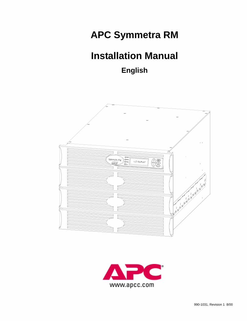
APC Symmetra RM
Installation ManualEnglish
990-1031, Revision 1 8/00
Limited Warranty
American Power Conversion (APC) warrants its products to be free from defects in materials and workmanshipfor a period of two years from the date of purchase, except in India where the period is one year for batterymodule(s). Its obligation under this warranty is limited to repairing or replacing, at its own sole option, anysuch defective products. To obtain service under warranty you must obtain a Returned Material Authorization(RMA) number from customer support (see Service in the SYMMETRA RM OPERATION MANUAL). Productsmust be returned with transportation charges prepaid and must be accompanied by a brief description of theproblem encountered and proof of date and place of purchase. This warranty does not apply to equipmentwhich has been damaged by accident, negligence, or misapplication or has been altered or modified in any way.This warranty applies only to the original purchaser who must have properly registered the product within 10days of purchase.EXCEPT AS PROVIDED HEREIN, AMERICAN POWER CONVERSION MAKES NO WARRANTIES,EXPRESSED OR IMPLIED, INCLUDING WARRANTIES OF MERCHANTABILITY AND FITNESS FORA PARTICULAR PURPOSE. Some states do not permit limitation or exclusion of implied warranties;therefore, the aforesaid limitation(s) or exclusion(s) may not apply to the purchaser.EXCEPT AS PROVIDED ABOVE, IN NO EVENT WILL APC BE LIABLE FOR DIRECT, INDIRECT,SPECIAL, INCIDENTAL, OR CONSEQUENTIAL DAMAGES ARISING OUT OF THE USE OF THISPRODUCT, EVEN IF ADVISED OF THE POSSIBILITY OF SUCH DAMAGE. Specifically, APC is notliable for any costs, such as lost profits or revenue, loss of equipment, loss of use of equipment, loss ofsoftware, loss of data, costs of substitutes, claims by third parties, or otherwise. This warranty gives youspecific legal rights and you may also have other rights which vary from state to state.
Life Support Policy
As a general policy, American Power Conversion (APC) does not recommend the use of any of its products inlife support applications where failure or malfunction of the APC product can be reasonably expected to causefailure of the life support device or to significantly affect its safety or effectiveness. APC does not recommendthe use of any of its products in direct patient care. APC will not knowingly sell its products for use in suchapplications unless it receives in writing assurances satisfactory to APC that (a) the risks of injury or damagehave been minimized, (b) the customer assumes all such risks, and (c) the liability of American PowerConversion is adequately protected under the circumstances.
Examples of devices considered to be life support devices are neonatal oxygen analyzers, nerve stimulators(whether used for anesthesia, pain relief, or other purposes), autotransfusion devices, blood pumps,defibrillators, arrhythmia detectors and alarms, pacemakers, hemodialysis systems, peritoneal dialysis systems,neonatal ventilator incubators, ventilators for both adults and infants, anesthesia ventilators, infusion pumps,and any other device designated as “critical” by the U.S.F.D.A.
Hospital grade wiring devices and leakage current may be ordered as options on many APC UPS systems. APCdoes not claim that units with this modification are certified or listed as Hospital Grade by APC or any otherorganization. Therefore these units do not meet the requirements for use in direct patient care.
Entire contents copyright © 2000 by American Power Conversion Corporation. All rights reserved.Reproduction in whole or in part without permission is prohibited.APC and PowerChute are registered trademarks of American Power Conversion Corporation. All othertrademarks are the property of their respective owners.
990-1031, Revision 1 8/00
Table of ContentsChapter 1: Safety Information ............................................................. 1
Conventions Used in this Manual ......................................................... 1Handling Safety..................................................................................... 1Electrical Safety .................................................................................... 1Deenergizing Safety .............................................................................. 2Battery Safety........................................................................................ 2Recycling of Batteries ........................................................................... 3Radio Frequency Interference ............................................................... 3
Chapter 2: Basics ................................................................................... 5
About Your UPS ................................................................................... 5How To Contact APC ........................................................................... 6
North America ................................................................................... 6Latin America, South America.......................................................... 6Europe, Middle East, and Africa ....................................................... 6Japan, Asia, Australia ........................................................................ 6
Product Overview.................................................................................. 7Front View Component Identification............................................... 7Rear View Component Identification................................................ 8System Block Diagram.................................................................... 10
Chapter 3: Installation ........................................................................ 11Unpacking ........................................................................................... 11
Inspection ........................................................................................ 11Contents........................................................................................... 11Placement ........................................................................................ 11
Installing the Symmetra RM ............................................................... 11Position the Symmetra RM ............................................................. 11Connect the Symmetra RM to its Power Source ............................. 13Wire the Emergency Power Off (EPO) Switch ............................... 14Install Modules Into the Symmetra RM Frame ............................... 15Connect Equipment to the Symmetra RM....................................... 16
Appendix A: Electrical Wiring Checklist ......................................... 17
990-1031, Revision 1 8/00
List of FiguresFigure 1: Symmetra RM..................................................................................................................................... 5Figure 2: Front View of the Symmetra RM ....................................................................................................... 7Figure 3: Rear View of the Symmetra RM (200/208 Vac / L1-L2-G version shown)....................................... 8Figure 4: System Block Diagram ..................................................................................................................... 10Figure 5: EPO Connection Option 1 ................................................................................................................ 15Figure 6: EPO Connection Option 2 ................................................................................................................ 15Figure 7: Bay Identification ............................................................................................................................. 15Figure 8: Power Distribution Panels ................................................................................................................ 16
1
CHAPTER 1: SAFETY INFORMATIONThis Safety section contains important instructions that should be followed during installation and maintenanceof the APC equipment and batteries. It is intended for APC customers who setup, install, relocate, or maintainAPC equipment.
Connection to the branch circuit (mains) must be performed by a Licensed Electrician. Installation andremoval of the Power, Battery, and Intelligence modules must be performed by service personnel.Installation and removal of interface accessories must be performed by service personnel. Operation ofthe Symmetra RM can be performed by any individual with no previous technical experience.
Conventions Used in this ManualThis section defines the symbols used throughout this manual. Carefully read all information boxes and abideby the instructions.
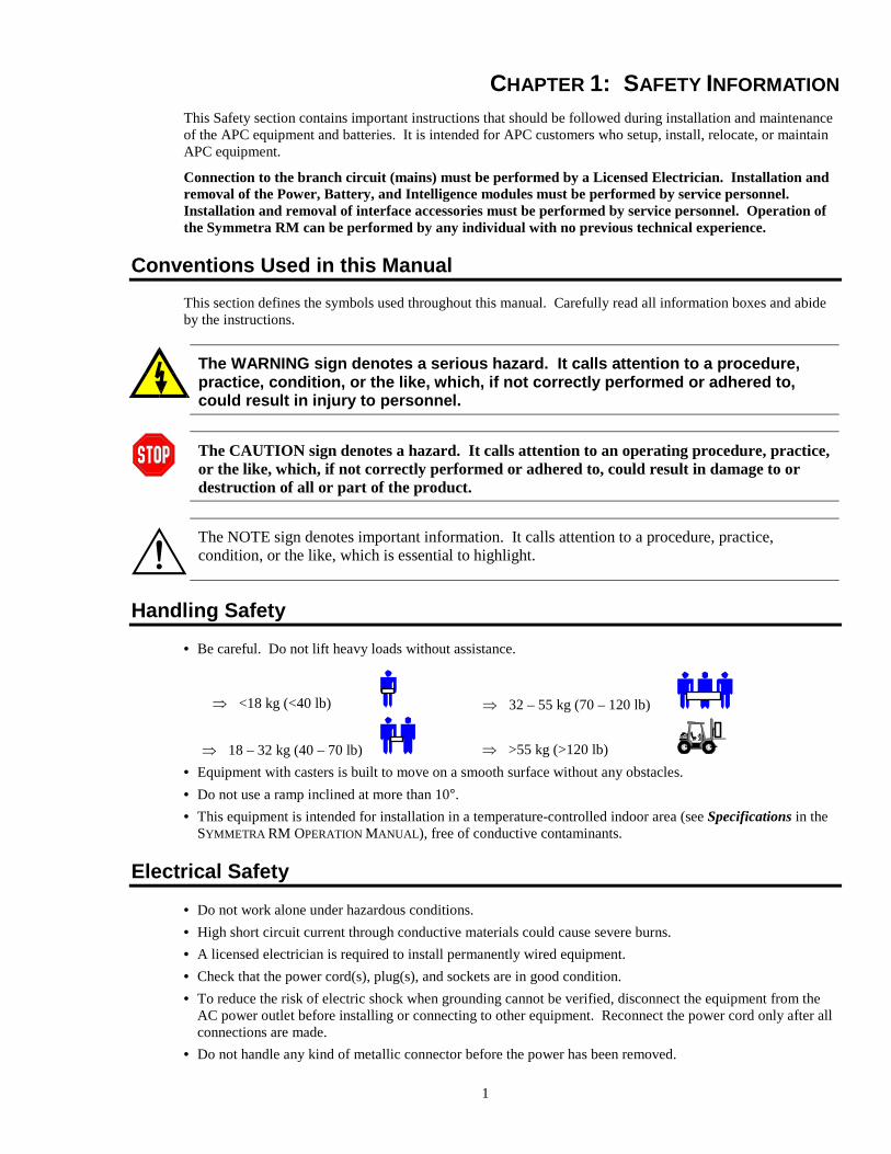
The WARNING sign denotes a serious hazard. It calls attention to a procedure,practice, condition, or the like, which, if not correctly performed or adhered to,could result in injury to personnel.
The CAUTION sign denotes a hazard. It calls attention to an operating procedure, practice,or the like, which, if not correctly performed or adhered to, could result in damage to ordestruction of all or part of the product.
The NOTE sign denotes important information. It calls attention to a procedure, practice,condition, or the like, which is essential to highlight.
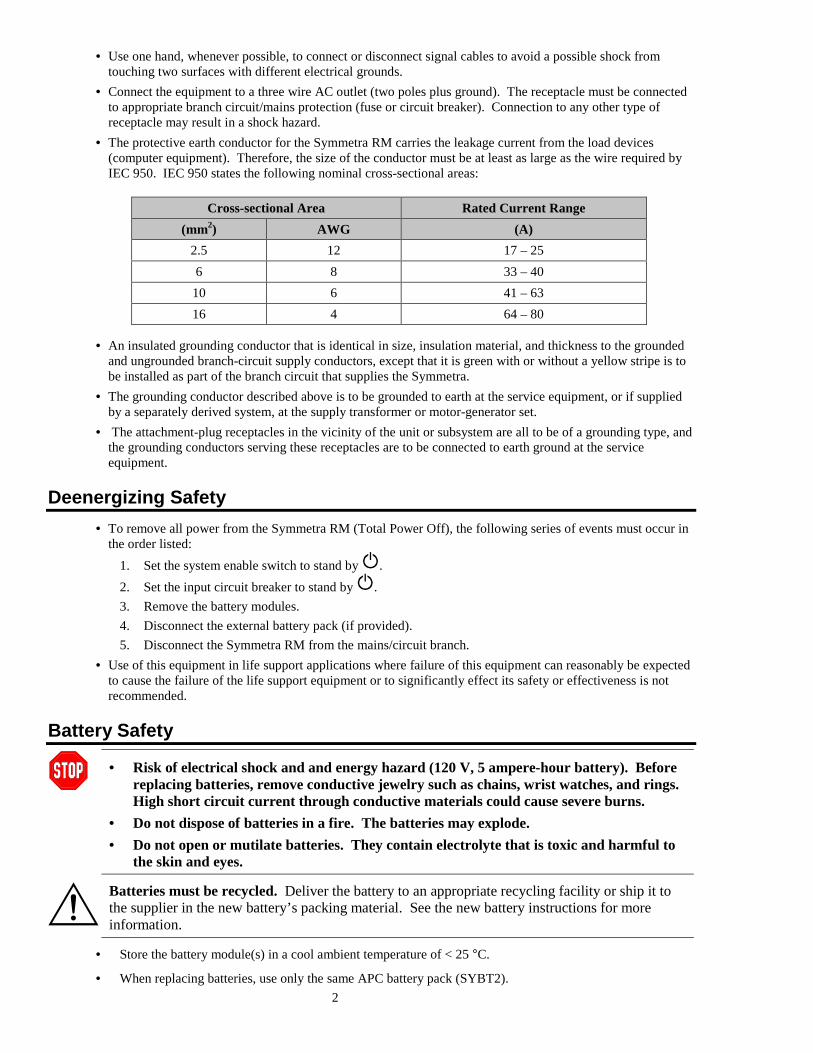
Handling Safety• Be careful. Do not lift heavy loads without assistance.
� <18 kg (<40 lb)
� 18 – 32 kg (40 – 70 lb)
� 32 – 55 kg (70 – 120 lb)
� >55 kg (>120 lb)• Equipment with casters is built to move on a smooth surface without any obstacles.• Do not use a ramp inclined at more than 10°.• This equipment is intended for installation in a temperature-controlled indoor area (see Specifications in the
SYMMETRA RM OPERATION MANUAL), free of conductive contaminants.
Electrical Safety• Do not work alone under hazardous conditions.• High short circuit current through conductive materials could cause severe burns.• A licensed electrician is required to install permanently wired equipment.• Check that the power cord(s), plug(s), and sockets are in good condition.• To reduce the risk of electric shock when grounding cannot be verified, disconnect the equipment from the
AC power outlet before installing or connecting to other equipment. Reconnect the power cord only after allconnections are made.
• Do not handle any kind of metallic connector before the power has been removed.
2
• Use one hand, whenever possible, to connect or disconnect signal cables to avoid a possible shock fromtouching two surfaces with different electrical grounds.
• Connect the equipment to a three wire AC outlet (two poles plus ground). The receptacle must be connectedto appropriate branch circuit/mains protection (fuse or circuit breaker). Connection to any other type ofreceptacle may result in a shock hazard.
• The protective earth conductor for the Symmetra RM carries the leakage current from the load devices(computer equipment). Therefore, the size of the conductor must be at least as large as the wire required byIEC 950. IEC 950 states the following nominal cross-sectional areas:
Cross-sectional Area Rated Current Range(mm2) AWG (A)
2.5 12 17 – 256 8 33 – 40
10 6 41 – 6316 4 64 – 80
• An insulated grounding conductor that is identical in size, insulation material, and thickness to the groundedand ungrounded branch-circuit supply conductors, except that it is green with or without a yellow stripe is tobe installed as part of the branch circuit that supplies the Symmetra.
• The grounding conductor described above is to be grounded to earth at the service equipment, or if suppliedby a separately derived system, at the supply transformer or motor-generator set.
• The attachment-plug receptacles in the vicinity of the unit or subsystem are all to be of a grounding type, andthe grounding conductors serving these receptacles are to be connected to earth ground at the serviceequipment.
Deenergizing Safety• To remove all power from the Symmetra RM (Total Power Off), the following series of events must occur in
the order listed:1. Set the system enable switch to stand by .2. Set the input circuit breaker to stand by .3. Remove the battery modules.4. Disconnect the external battery pack (if provided).5. Disconnect the Symmetra RM from the mains/circuit branch.
• Use of this equipment in life support applications where failure of this equipment can reasonably be expectedto cause the failure of the life support equipment or to significantly effect its safety or effectiveness is notrecommended.
Battery Safety
• Risk of electrical shock and and energy hazard (120 V, 5 ampere-hour battery). Beforereplacing batteries, remove conductive jewelry such as chains, wrist watches, and rings.High short circuit current through conductive materials could cause severe burns.
• Do not dispose of batteries in a fire. The batteries may explode.• Do not open or mutilate batteries. They contain electrolyte that is toxic and harmful to
the skin and eyes.
Batteries must be recycled. Deliver the battery to an appropriate recycling facility or ship it tothe supplier in the new battery’s packing material. See the new battery instructions for moreinformation.
• Store the battery module(s) in a cool ambient temperature of < 25 °C.
• When replacing batteries, use only the same APC battery pack (SYBT2).
3
Recycling of BatteriesSee your dealer or Replacing Modules in the SYMMETRA RM OPERATION MANUAL, for information onreplacement battery kits and battery recycling.
• Do not install the battery module(s) in the frame until you are ready to power up theSymmetra RM. Failure to so can result in a deep discharge of the batteries, which maycause permanent damage.
• Store the battery module(s) in a cool ambient temperature of < 25 °°°°C.
Radio Frequency InterferenceThis equipment has been tested and found to comply with the limits for a Class A digital device, pursuant topart 15 of the FCC Rules. These limits are designed to provide reasonable protection against harmfulinterference when the equipment is operated in a commercial environment. This equipment generates, uses, andcan radiate radio frequency energy and, if not installed and used in accordance with the instruction manual, maycause harmful interference to radio communications. Operation of this equipment in a residential area is likelyto cause harmful interference in which case the user will be required to correct the interference at his ownexpense.
Shielded signal cables must be used with this product to ensure compliance with the Class A FCC limits.

4
5
CHAPTER 2: BASICS
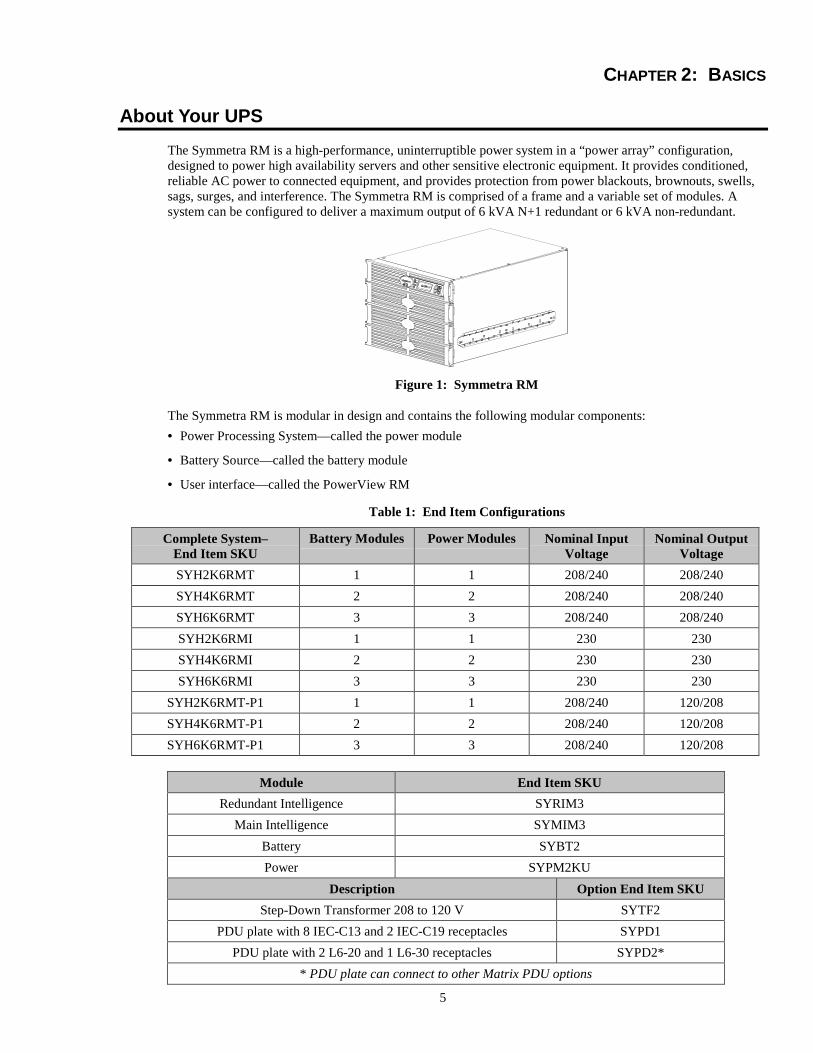
About Your UPSThe Symmetra RM is a high-performance, uninterruptible power system in a “power array” configuration,designed to power high availability servers and other sensitive electronic equipment. It provides conditioned,reliable AC power to connected equipment, and provides protection from power blackouts, brownouts, swells,sags, surges, and interference. The Symmetra RM is comprised of a frame and a variable set of modules. Asystem can be configured to deliver a maximum output of 6 kVA N+1 redundant or 6 kVA non-redundant.
Figure 1: Symmetra RM
The Symmetra RM is modular in design and contains the following modular components:• Power Processing System—called the power module
• Battery Source—called the battery module
• User interface—called the PowerView RM
Table 1: End Item Configurations
Complete System–End Item SKU
Battery Modules Power Modules Nominal InputVoltage
Nominal OutputVoltage
SYH2K6RMT 1 1 208/240 208/240SYH4K6RMT 2 2 208/240 208/240SYH6K6RMT 3 3 208/240 208/240SYH2K6RMI 1 1 230 230SYH4K6RMI 2 2 230 230SYH6K6RMI 3 3 230 230
SYH2K6RMT-P1 1 1 208/240 120/208SYH4K6RMT-P1 2 2 208/240 120/208SYH6K6RMT-P1 3 3 208/240 120/208
Module End Item SKURedundant Intelligence SYRIM3
Main Intelligence SYMIM3Battery SYBT2Power SYPM2KU
Description Option End Item SKUStep-Down Transformer 208 to 120 V SYTF2
PDU plate with 8 IEC-C13 and 2 IEC-C19 receptacles SYPD1PDU plate with 2 L6-20 and 1 L6-30 receptacles SYPD2*
* PDU plate can connect to other Matrix PDU options

6
How To Contact APCInternet http://www.apc.com/support
North AmericaPhone 1.800.800.4272Fax 1.401.788.2743Email [email protected]
Latin America, South AmericaArgentina .....0800.9.APCC (0800.9.2722) Mexico....................... 95.800.804.4283Brazil ...........0800.12.72.21 Uruguay..................... 000.413.598.2139Colombia .....980.15.39.47 Venezuela.................. 8001.2544
Europe, Middle East, and AfricaPhone................+353 91 702020 Email ...............apceurtech @ apcc.comFax....................+353 91 755275 Web support ....www.apc.com/support - eSupport
Ireland...............1 800 702000 x 2045 Italy ........................800 874 731Austria ..............0800 29 64 80 Luxembourg...........0800 2091Belgium ............0800 15063 Norway...................800 11 632Czech Republic.0800 102063 Poland ....................00800 353 1202Denmark ...........800 18 153 Portugal ..................0800 853 182Finland..............9800 13 374 Russia.....................007 095 9167166 (toll number)France ...............0800 906 483 South Africa ...........0800 994206Germany ...........0800 180 1227 Spain ......................900 95 35 33Greece...............00800 353 12206 Sweden...................020 795 419Holland .............0800 0224655 Switzerland ............0800 556177Hungary............06800 12221 Turkey....................0800 35390275Israel .................177 353 2206 United Kingdom.....0800 132990
Japan, Asia, AustraliaAustralia, New Zealand ........................................... +61 2 9955 9366, 1-800-652-725Singapore, Thailand, Vietnam................................. +65 398 1000Malaysia .................................................................. +60 3 756 8786Indonesia ................................................................. +62 21 6500813China ....................................................................... +86 10 8529 9888Hong Kong .............................................................. +85 2 2834 5001Taiwan..................................................................... +88 622 755 1945India, Nepal, Sri Lanka, Bangladesh, Maldives....... +91 44 433 1124Japan........................................................................ +81 3 5434 2021Korea ....................................................................... +82 2 501 6492Philippines ............................................................... +63 2 813 2662
7
Product Overview
Front View Component Identification
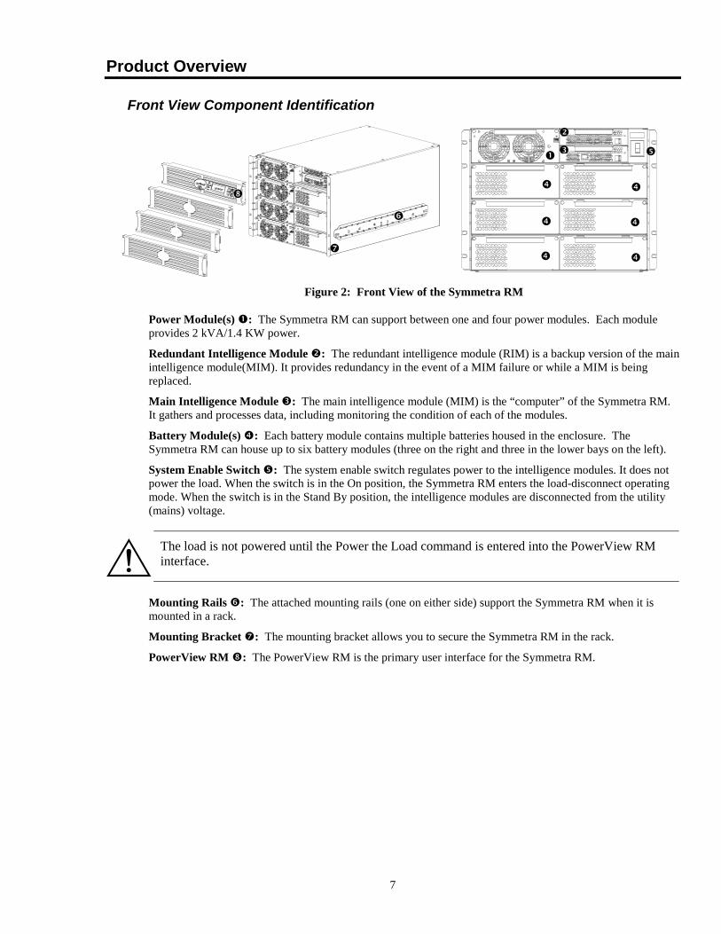
Figure 2: Front View of the Symmetra RM
Power Module(s) �: The Symmetra RM can support between one and four power modules. Each moduleprovides 2 kVA/1.4 KW power.
Redundant Intelligence Module �: The redundant intelligence module (RIM) is a backup version of the mainintelligence module(MIM). It provides redundancy in the event of a MIM failure or while a MIM is beingreplaced.
Main Intelligence Module �: The main intelligence module (MIM) is the “computer” of the Symmetra RM.It gathers and processes data, including monitoring the condition of each of the modules.
Battery Module(s) �: Each battery module contains multiple batteries housed in the enclosure. TheSymmetra RM can house up to six battery modules (three on the right and three in the lower bays on the left).
System Enable Switch �: The system enable switch regulates power to the intelligence modules. It does notpower the load. When the switch is in the On position, the Symmetra RM enters the load-disconnect operatingmode. When the switch is in the Stand By position, the intelligence modules are disconnected from the utility(mains) voltage.
The load is not powered until the Power the Load command is entered into the PowerView RMinterface.
Mounting Rails �: The attached mounting rails (one on either side) support the Symmetra RM when it ismounted in a rack.
Mounting Bracket �: The mounting bracket allows you to secure the Symmetra RM in the rack.
PowerView RM �: The PowerView RM is the primary user interface for the Symmetra RM.
�
�
�
�
�
�
��
� �
�
�
�
8
Rear View Component Identification
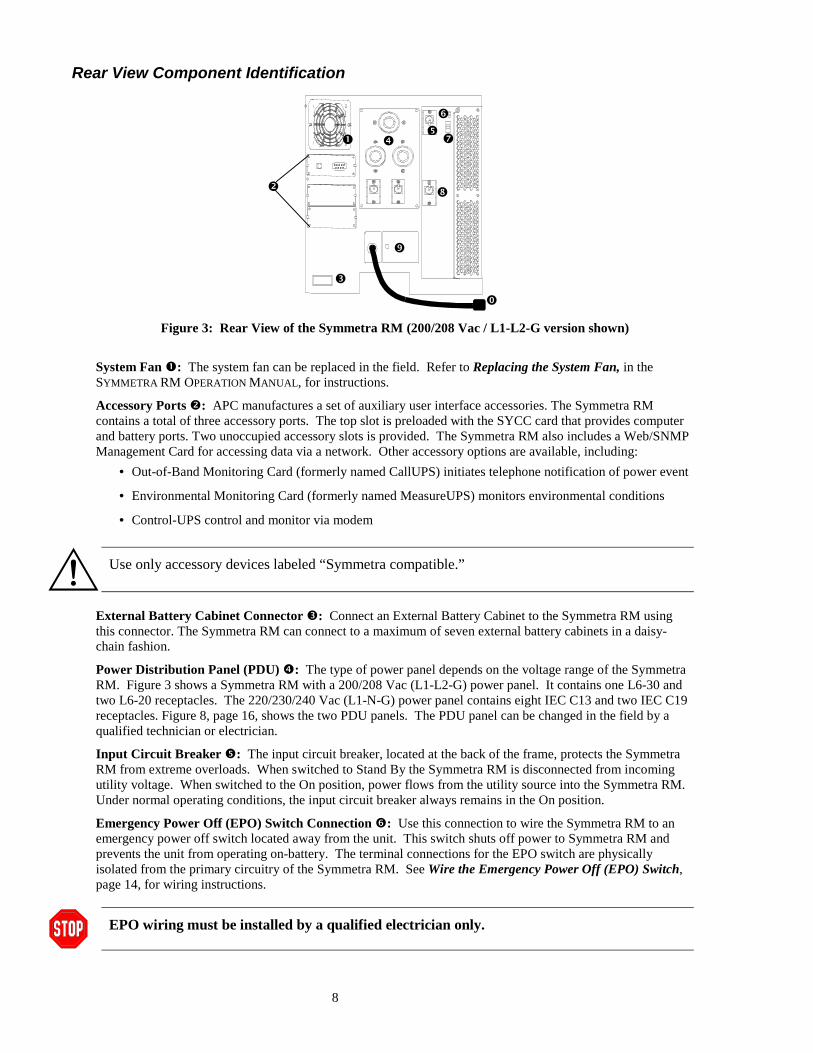
Figure 3: Rear View of the Symmetra RM (200/208 Vac / L1-L2-G version shown)
System Fan �: The system fan can be replaced in the field. Refer to Replacing the System Fan, in theSYMMETRA RM OPERATION MANUAL, for instructions.
Accessory Ports �: APC manufactures a set of auxiliary user interface accessories. The Symmetra RMcontains a total of three accessory ports. The top slot is preloaded with the SYCC card that provides computerand battery ports. Two unoccupied accessory slots is provided. The Symmetra RM also includes a Web/SNMPManagement Card for accessing data via a network. Other accessory options are available, including:
• Out-of-Band Monitoring Card (formerly named CallUPS) initiates telephone notification of power event
• Environmental Monitoring Card (formerly named MeasureUPS) monitors environmental conditions
• Control-UPS control and monitor via modem
Use only accessory devices labeled “Symmetra compatible.”
External Battery Cabinet Connector �: Connect an External Battery Cabinet to the Symmetra RM usingthis connector. The Symmetra RM can connect to a maximum of seven external battery cabinets in a daisy-chain fashion.
Power Distribution Panel (PDU) �: The type of power panel depends on the voltage range of the SymmetraRM. Figure 3 shows a Symmetra RM with a 200/208 Vac (L1-L2-G) power panel. It contains one L6-30 andtwo L6-20 receptacles. The 220/230/240 Vac (L1-N-G) power panel contains eight IEC C13 and two IEC C19receptacles. Figure 8, page 16, shows the two PDU panels. The PDU panel can be changed in the field by aqualified technician or electrician.
Input Circuit Breaker �: The input circuit breaker, located at the back of the frame, protects the SymmetraRM from extreme overloads. When switched to Stand By the Symmetra RM is disconnected from incomingutility voltage. When switched to the On position, power flows from the utility source into the Symmetra RM.Under normal operating conditions, the input circuit breaker always remains in the On position.
Emergency Power Off (EPO) Switch Connection �: Use this connection to wire the Symmetra RM to anemergency power off switch located away from the unit. This switch shuts off power to Symmetra RM andprevents the unit from operating on-battery. The terminal connections for the EPO switch are physicallyisolated from the primary circuitry of the Symmetra RM. See Wire the Emergency Power Off (EPO) Switch,page 14, for wiring instructions.
EPO wiring must be installed by a qualified electrician only.
�
�
�
��
�
�
�
9
Input Voltage Selection Switch �: Set this switch to the appropriate setting, either 200/208 (L1-L2-G) or220/230/240 (L1-N-G) before powering up the Symmetra RM.
Products rated 200/208 are typically installed in North America (208 V, phase to phase, grounding conductor)and Japan (200V, phase to phase, grounding conductor).
Products rated 2020/230/240 are typically installed in the rest of the world (220 V, 230 V, or 240 V, phase toneutral, protective earth). These products must be hard wired to the input power.
Maintenance Bypass Switch �: When switched to the On position, the maintenance bypass switch bypassesthe Symmetra RM, and causes the load equipment to be powered directly from utility power. When it isswitched to the Off position, utility power flows into the Symmetra RM, and conditioned power is delivered tothe load equipment. Under normal operating conditions, the maintenance bypass switch remains in the Offposition.
The load equipment is unprotected when the maintenance bypass switch is in the On position.
Input Wiring Access Panels : Provides access to wiring terminal blocks for input wiring. The 200/208(L1-L2-G) version must be hard wired if the load is greater than 5 kVA. The 220/230/240 (L1-N-G) versionmust always be hard wired.
Input Power Cord [on 200/208 (L1-L2-G) versions only]: The 200/208 (L1-L2-G) version can use theline cord to connect to the power source if the load is less than 5 kVA. If the load is greater than 5 kVA, theunit must be hard wired to the power source. The 220/230/240 (L1-N-G) version must always be hard wired.
10
System Block Diagram
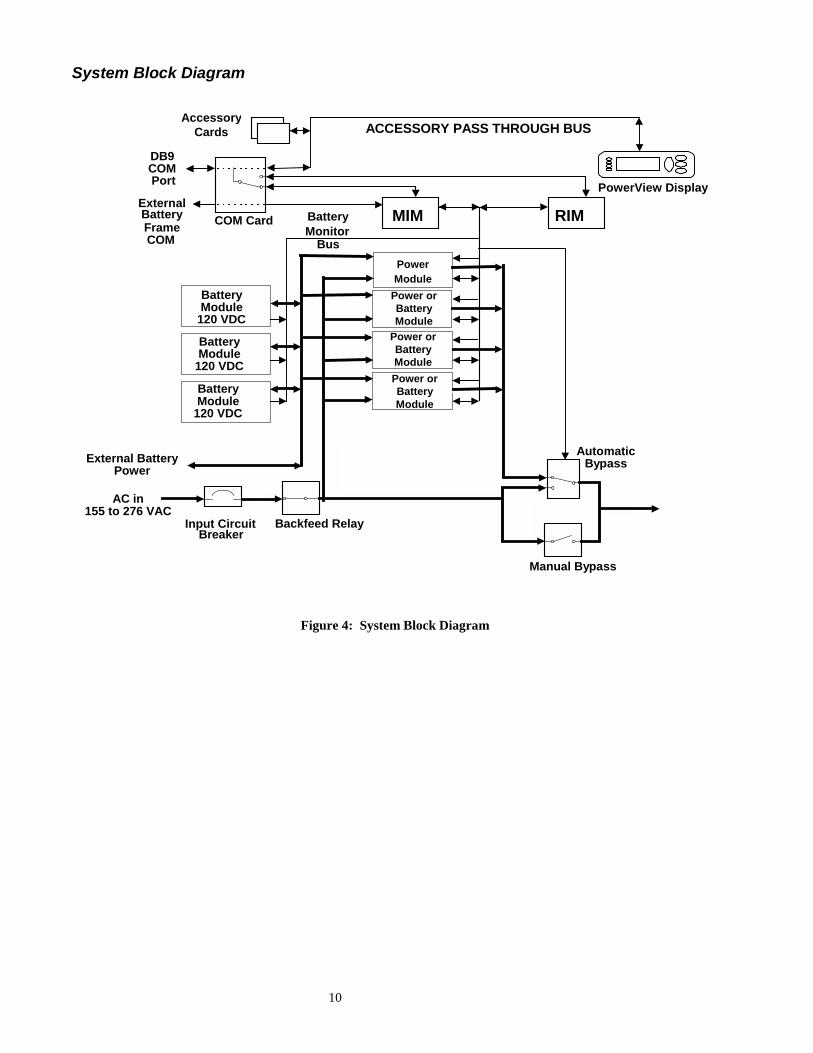
Figure 4: System Block Diagram
MIM RIMCOM Card
AccessoryCards
PowerView Display
DB9COMPort
BatteryMonitor
Bus
External BatteryPower
Input CircuitBreaker
ACCESSORY PASS THROUGH BUS
Backfeed Relay
AutomaticBypass
Manual Bypass
ExternalBatteryFrameCOM
Power orBatteryModule
Power orBatteryModulePower orBatteryModule
BatteryModule
120 VDC
PowerModule
AC in155 to 276 VAC
BatteryModule
120 VDC
BatteryModule
120 VDC
11
CHAPTER 3: INSTALLATION
UnpackingAPC has taken care to design robust packaging for your product. However, accidents and damage may occurduring shipment.
InspectionInspect the UPS upon receipt. Notify the carrier and dealer if there is damage. The packaging is recyclable;save it for reuse or dispose of it properly.
ContentsThe shipping package contains the UPS, one PowerView display bezel, three blank bezels, the mounting rail kit(containing the mounting rails, and hardware), one blank panel kit (containing five blank panels, screws andinstructions), and a literature kit.
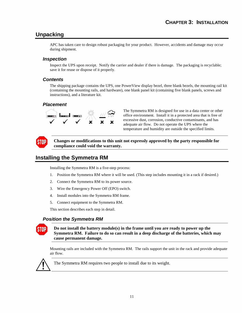
Placement
S m a r t - U P SS m a r t - U P S
S m a r t - U P S
The Symmetra RM is designed for use in a data center or otheroffice environment. Install it in a protected area that is free ofexcessive dust, corrosion, conductive contaminants, and hasadequate air flow. Do not operate the UPS where thetemperature and humidity are outside the specified limits.
Changes or modifications to this unit not expressly approved by the party responsible forcompliance could void the warranty.
Installing the Symmetra RMInstalling the Symmetra RM is a five-step process:
1. Position the Symmetra RM where it will be used. (This step includes mounting it in a rack if desired.)
2. Connect the Symmetra RM to its power source.
3. Wire the Emergency Power Off (EPO) switch.
4. Install modules into the Symmetra RM frame.
5. Connect equipment to the Symmetra RM.
This section describes each step in detail.
Position the Symmetra RM
Do not install the battery module(s) in the frame until you are ready to power up theSymmetra RM. Failure to do so can result in a deep discharge of the batteries, which maycause permanent damage.
Mounting rails are included with the Symmetra RM. The rails support the unit in the rack and provide adequateair flow.
The Symmetra RM requires two people to install due to its weight.
12
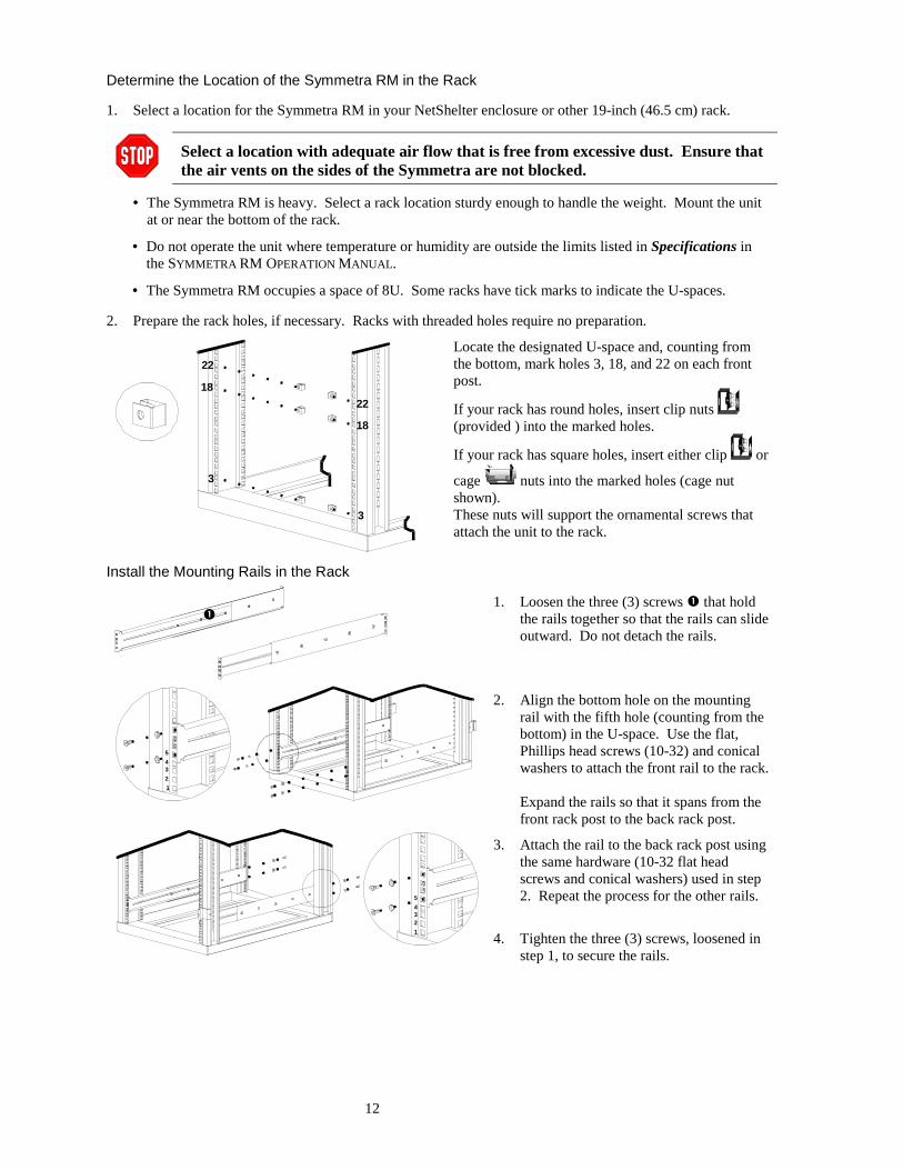
Determine the Location of the Symmetra RM in the Rack
1. Select a location for the Symmetra RM in your NetShelter enclosure or other 19-inch (46.5 cm) rack.
Select a location with adequate air flow that is free from excessive dust. Ensure thatthe air vents on the sides of the Symmetra are not blocked.
• The Symmetra RM is heavy. Select a rack location sturdy enough to handle the weight. Mount the unitat or near the bottom of the rack.
• Do not operate the unit where temperature or humidity are outside the limits listed in Specifications inthe SYMMETRA RM OPERATION MANUAL.
• The Symmetra RM occupies a space of 8U. Some racks have tick marks to indicate the U-spaces.
2. Prepare the rack holes, if necessary. Racks with threaded holes require no preparation.
22
18
3
22
3
18
Locate the designated U-space and, counting fromthe bottom, mark holes 3, 18, and 22 on each frontpost.
If your rack has round holes, insert clip nuts (provided ) into the marked holes.
If your rack has square holes, insert either clip or
cage nuts into the marked holes (cage nutshown).These nuts will support the ornamental screws thatattach the unit to the rack.
Install the Mounting Rails in the Rack
1. Loosen the three (3) screws � that holdthe rails together so that the rails can slideoutward. Do not detach the rails.
12345
2. Align the bottom hole on the mountingrail with the fifth hole (counting from thebottom) in the U-space. Use the flat,Phillips head screws (10-32) and conicalwashers to attach the front rail to the rack.
Expand the rails so that it spans from thefront rack post to the back rack post.
12345
3. Attach the rail to the back rack post usingthe same hardware (10-32 flat headscrews and conical washers) used in step2. Repeat the process for the other rails.
4. Tighten the three (3) screws, loosened instep 1, to secure the rails.
�
13
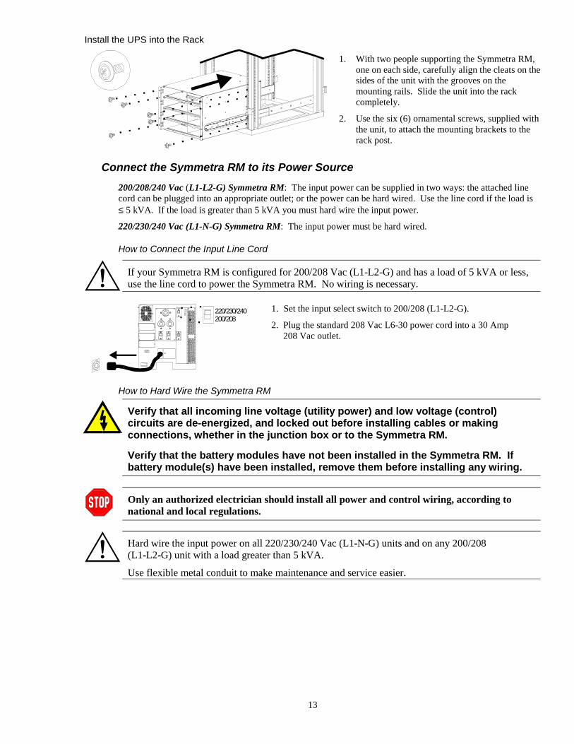
Install the UPS into the Rack
1. With two people supporting the Symmetra RM,one on each side, carefully align the cleats on thesides of the unit with the grooves on themounting rails. Slide the unit into the rackcompletely.
2. Use the six (6) ornamental screws, supplied withthe unit, to attach the mounting brackets to therack post.
Connect the Symmetra RM to its Power Source200/208/240 Vac (L1-L2-G) Symmetra RM: The input power can be supplied in two ways: the attached linecord can be plugged into an appropriate outlet; or the power can be hard wired. Use the line cord if the load is≤ 5 kVA. If the load is greater than 5 kVA you must hard wire the input power.
220/230/240 Vac (L1-N-G) Symmetra RM: The input power must be hard wired.
How to Connect the Input Line Cord
If your Symmetra RM is configured for 200/208 Vac (L1-L2-G) and has a load of 5 kVA or less,use the line cord to power the Symmetra RM. No wiring is necessary.
220/230/240200/208
1. Set the input select switch to 200/208 (L1-L2-G).
2. Plug the standard 208 Vac L6-30 power cord into a 30 Amp208 Vac outlet.
How to Hard Wire the Symmetra RM
Verify that all incoming line voltage (utility power) and low voltage (control)circuits are de-energized, and locked out before installing cables or makingconnections, whether in the junction box or to the Symmetra RM.
Verify that the battery modules have not been installed in the Symmetra RM. Ifbattery module(s) have been installed, remove them before installing any wiring.
Only an authorized electrician should install all power and control wiring, according tonational and local regulations.
Hard wire the input power on all 220/230/240 Vac (L1-N-G) units and on any 200/208(L1-L2-G) unit with a load greater than 5 kVA.
Use flexible metal conduit to make maintenance and service easier.
14
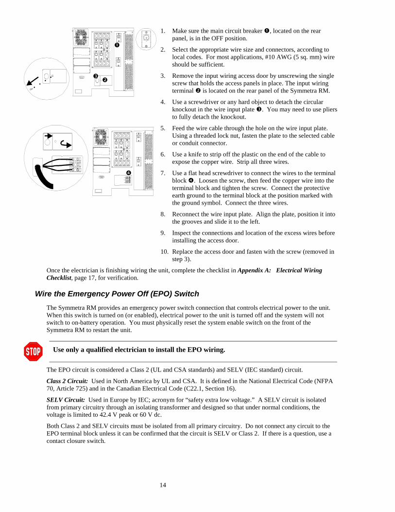
1. Make sure the main circuit breaker �, located on the rearpanel, is in the OFF position.
2. Select the appropriate wire size and connectors, according tolocal codes. For most applications, #10 AWG (5 sq. mm) wireshould be sufficient.
3. Remove the input wiring access door by unscrewing the singlescrew that holds the access panels in place. The input wiringterminal � is located on the rear panel of the Symmetra RM.
4. Use a screwdriver or any hard object to detach the circularknockout in the wire input plate �. You may need to use pliersto fully detach the knockout.
5. Feed the wire cable through the hole on the wire input plate.Using a threaded lock nut, fasten the plate to the selected cableor conduit connector.
6. Use a knife to strip off the plastic on the end of the cable toexpose the copper wire. Strip all three wires.
7. Use a flat head screwdriver to connect the wires to the terminalblock �. Loosen the screw, then feed the copper wire into theterminal block and tighten the screw. Connect the protectiveearth ground to the terminal block at the position marked withthe ground symbol. Connect the three wires.
8. Reconnect the wire input plate. Align the plate, position it intothe grooves and slide it to the left.
9. Inspect the connections and location of the excess wires beforeinstalling the access door.
10. Replace the access door and fasten with the screw (removed instep 3).
Once the electrician is finishing wiring the unit, complete the checklist in Appendix A: Electrical WiringChecklist, page 17, for verification.
Wire the Emergency Power Off (EPO) SwitchThe Symmetra RM provides an emergency power switch connection that controls electrical power to the unit.When this switch is turned on (or enabled), electrical power to the unit is turned off and the system will notswitch to on-battery operation. You must physically reset the system enable switch on the front of theSymmetra RM to restart the unit.
Use only a qualified electrician to install the EPO wiring.
The EPO circuit is considered a Class 2 (UL and CSA standards) and SELV (IEC standard) circuit.
Class 2 Circuit: Used in North America by UL and CSA. It is defined in the National Electrical Code (NFPA70, Article 725) and in the Canadian Electrical Code (C22.1, Section 16).
SELV Circuit: Used in Europe by IEC; acronym for “safety extra low voltage.” A SELV circuit is isolatedfrom primary circuitry through an isolating transformer and designed so that under normal conditions, thevoltage is limited to 42.4 V peak or 60 V dc.
Both Class 2 and SELV circuits must be isolated from all primary circuitry. Do not connect any circuit to theEPO terminal block unless it can be confirmed that the circuit is SELV or Class 2. If there is a question, use acontact closure switch.
�
��
�
15
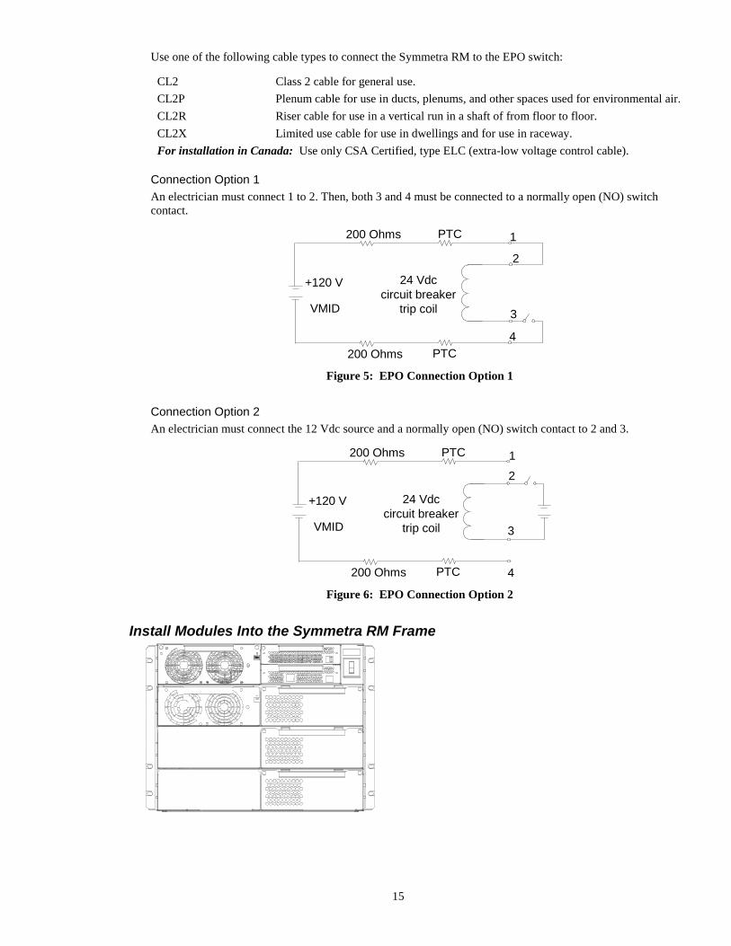
Use one of the following cable types to connect the Symmetra RM to the EPO switch:
CL2 Class 2 cable for general use.CL2P Plenum cable for use in ducts, plenums, and other spaces used for environmental air.CL2R Riser cable for use in a vertical run in a shaft of from floor to floor.CL2X Limited use cable for use in dwellings and for use in raceway.For installation in Canada: Use only CSA Certified, type ELC (extra-low voltage control cable).
Connection Option 1An electrician must connect 1 to 2. Then, both 3 and 4 must be connected to a normally open (NO) switchcontact.
PTC
PTC200 Ohms
200 Ohms
+120 V
VMID
24 Vdccircuit breaker
trip coil
1
2
3
4
Figure 5: EPO Connection Option 1
Connection Option 2An electrician must connect the 12 Vdc source and a normally open (NO) switch contact to 2 and 3.
PTC
PTC200 Ohms
200 Ohms
+120 V
VMID
24 Vdccircuit breaker
trip coil
12
3
4
Figure 6: EPO Connection Option 2
Install Modules Into the Symmetra RM Frame
16
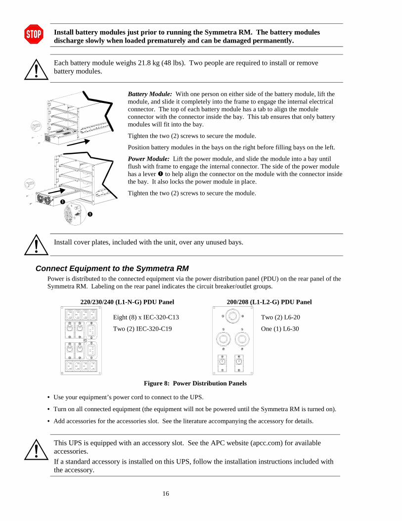
Install battery modules just prior to running the Symmetra RM. The battery modulesdischarge slowly when loaded prematurely and can be damaged permanently.
Each battery module weighs 21.8 kg (48 lbs). Two people are required to install or removebattery modules.
Battery Module: With one person on either side of the battery module, lift themodule, and slide it completely into the frame to engage the internal electricalconnector. The top of each battery module has a tab to align the moduleconnector with the connector inside the bay. This tab ensures that only batterymodules will fit into the bay.
Tighten the two (2) screws to secure the module.
Position battery modules in the bays on the right before filling bays on the left.
Power Module: Lift the power module, and slide the module into a bay untilflush with frame to engage the internal connector. The side of the power modulehas a lever � to help align the connector on the module with the connector insidethe bay. It also locks the power module in place.
Tighten the two (2) screws to secure the module.
Install cover plates, included with the unit, over any unused bays.
Connect Equipment to the Symmetra RMPower is distributed to the connected equipment via the power distribution panel (PDU) on the rear panel of theSymmetra RM. Labeling on the rear panel indicates the circuit breaker/outlet groups.
220/230/240 (L1-N-G) PDU Panel 200/208 (L1-L2-G) PDU Panel
Eight (8) x IEC-320-C13
Two (2) IEC-320-C19
Two (2) L6-20
One (1) L6-30
Figure 8: Power Distribution Panels
• Use your equipment’s power cord to connect to the UPS.
• Turn on all connected equipment (the equipment will not be powered until the Symmetra RM is turned on).
• Add accessories for the accessories slot. See the literature accompanying the accessory for details.
This UPS is equipped with an accessory slot. See the APC website (apcc.com) for availableaccessories.If a standard accessory is installed on this UPS, follow the installation instructions included withthe accessory.
�
�
17
APPENDIX A: ELECTRICAL WIRING CHECKLIST
Complete this checklist to ensure that the Symmetra RM has been wired properly.
Ensure that all switches (system enable, maintenance bypass, input circuit breaker, andbypass circuit breaker) are in the Off or Stand By position. Turn off or unplug allequipment connected to the Symmetra RM.
Ensure that the input voltage selection switch is in the appropriate position.
1. Apply power to the system input. Measure the voltage at the input terminal block. Record the measuredvoltages:
L1-L2 for 200/208 Vac __________________________________________
OR
L1-Neutral for 220/230/240 Vac: __________________________________
The measured voltage must be between 184 and 265 V. If it is not, do not continue! Verifythe wiring from the power source to the input wiring connections. Repeat step 1.
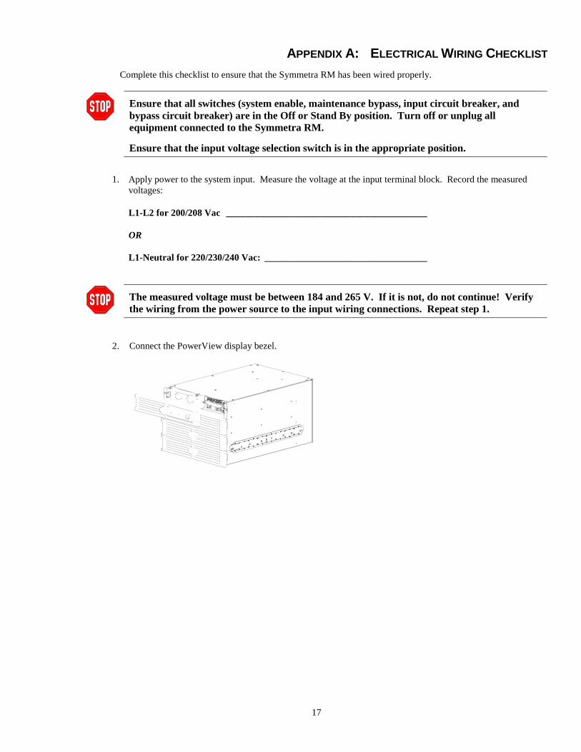
2. Connect the PowerView display bezel.
18
5. Record input voltages below and compare the values with the measured voltages from step 1. If the twomeasurements are significantly different, contact APC Symmetra technical support.
Vin 1: ________________________________________________________
6. Switch the maintenance bypass switch on.
Disregard any LED indicator or fault messages on the PowerView.
Record the output voltage, below, and compare the value with Vin 1 from step 5. If the two measurementsare significantly different, contact APC Symmetra technical support.
Reported Output Voltage: Out ______________________ V _________________________ Hz
7. Test the EPO switch. The system enable switch should physically move to the Stand By position, and thesystem should shut down completely. If this does not occur, check the connections and the EPO switch toensure that they are installed and functioning properly.
8. Successful completion of steps 1 through 7 indicate that the system wiring is properly installed. Turn offbreakers and switches and shut down input power to the system. Reinstall all wiring access panels on theframe.
Electrical Installation Completed by: _____________________________________________________
____________________________________________________
____________________________________________________