Embed Size (px)
Citation preview

Copyright 2004
IMPORTANT!
THIS DOCUMENT CONTAINS IMPORTANT SAFETY INSTRUCTIONS-
PLEASE SAVE THESE INSTRUCTIONS!
Symmetra MW 1000 kW 400 V
w/4-pole External Bypass SSW
Instal lat ion Guide


Contents
Safety ......................................................................1
IMPORTANT SAFETY INSTRUCTIONS - SAVE THESE INSTRUCTIONS . . . . . . . . . . . . . . . . . . . . . . . . . . 1
Symbols used in this guide . . . . . . . . . . . . . . . . . . . . . . . . . 1
Display and buttons . . . . . . . . . . . . . . . . . . . . . . . . . . . . . . 2
Installation safety . . . . . . . . . . . . . . . . . . . . . . . . . . . . . . . 3
System Overview......................................................5
UPS Sections . . . . . . . . . . . . . . . . . . . . . . . . . . . . . . . . . . . . . . . 5Inverter Section . . . . . . . . . . . . . . . . . . . . . . . . . . . . . . . . . 5
Control Section . . . . . . . . . . . . . . . . . . . . . . . . . . . . . . . . . 5
Input/Output Section . . . . . . . . . . . . . . . . . . . . . . . . . . . . . 5
Configurations . . . . . . . . . . . . . . . . . . . . . . . . . . . . . . . . . . . . . 6Configuration 1 (Inverter Section placed to the left) . . . . . . . . 6
Configuration 2 (Inverter Section placed to the right) . . . . . . . 7
External Bypass Static Switch. . . . . . . . . . . . . . . . . . . . . . . . . . . 8
Ancillary Equipment . . . . . . . . . . . . . . . . . . . . . . . . . . . . . . . . . 9APC Battery Breaker Box . . . . . . . . . . . . . . . . . . . . . . . . . . . 9
APC Maintenance Bypass Panel . . . . . . . . . . . . . . . . . . . . . . 9
Relay Board . . . . . . . . . . . . . . . . . . . . . . . . . . . . . . . . . . . 9
Mechanical Installation...........................................11
Installation of Rear Bottom Trims. . . . . . . . . . . . . . . . . . . . . . . 11
Positioning the UPS Sections . . . . . . . . . . . . . . . . . . . . . . . . . . 12Turning the frame-joining brackets . . . . . . . . . . . . . . . . . . . 12
Positioning Configuration 1 . . . . . . . . . . . . . . . . . . . . . . . 13
Positioning Configuration 2 . . . . . . . . . . . . . . . . . . . . . . . 15
Symmetra MW 1000 kW 400 V W/4-pole External Bypass SSW - Installation Guide - 990-2273 i

Seismic Anchoring . . . . . . . . . . . . . . . . . . . . . . . . . . . . . . . . . . 17Preparing for seismic anchoring . . . . . . . . . . . . . . . . . . . . 17
Seismic anchoring procedure . . . . . . . . . . . . . . . . . . . . . . 18
Interconnecting the UPS Sections. . . . . . . . . . . . . . . . . . . . . . . 19Temporary Removal of Main Static Switch . . . . . . . . . . . . . . 19
Attachment of Rear Assembly Bracket . . . . . . . . . . . . . . . . . . . 23
Attachment of Front Assembly Bracket. . . . . . . . . . . . . . . . . . . 24
Busbars and Control Wires. . . . . . . . . . . . . . . . . . . . . . . . . . . . 25Configuration I . . . . . . . . . . . . . . . . . . . . . . . . . . . . . . . . 26
Configuration II . . . . . . . . . . . . . . . . . . . . . . . . . . . . . . . 29
Preparing the Input/Output Section for busbar connection to the Control Section . . . . . . . . . . . . . . . . . . . . . . . . . . . . . 30
Busbar connections between Input/Output and Control Sections . . . . . . . . . . . . . . . . . . . . . . . . . . . . . . . 31
Reinstallation of the Main Static Switch . . . . . . . . . . . . . . . . . . 33
Busbar Connections after Reinstallation of Main Static Switch . 36Configuration 1 . . . . . . . . . . . . . . . . . . . . . . . . . . . . . . . 36
Configuration 2 . . . . . . . . . . . . . . . . . . . . . . . . . . . . . . . 37
Connection of internal control wires . . . . . . . . . . . . . . . . . . . . 39Connection of control wires between the Control Section and the Input/Output Section - Configuration 1 . . . . . . . . . . . . . 39
Connection of control wires between the Control Section and Input/Output Setion - Configuration 2 . . . . . . . . . . . . . . . . 40
Reconnection of cable removed at temporary removal of Main Static Switch - Configuration 1 and 2 . . . . . . . . . . . . . 40
Connection of communication cable between Control Section and Inverter Section - Configuration 1 . . . . . . . . . . . . . . . . 41
Connection of communication cable between Control Section and Inverter Section - Configuration 2 . . . . . . . . . . . . . . . . 42
Power Module Installation . . . . . . . . . . . . . . . . . . . . . . . . . . . . 43Crane components . . . . . . . . . . . . . . . . . . . . . . . . . . . . . 43
Crane assembly . . . . . . . . . . . . . . . . . . . . . . . . . . . . . . . . 44
Power Module installation procedure . . . . . . . . . . . . . . . . . 44
Electrical Installation ............................................. 47
Typical UPS Wiring . . . . . . . . . . . . . . . . . . . . . . . . . . . . . . . . . 47Power wiring overview . . . . . . . . . . . . . . . . . . . . . . . . . . 47
ii Symmetra MW 1000 kW 400 V W/4-pole External Bypass SSW - Installation Guide - 990-2273

External Disconnection Switches . . . . . . . . . . . . . . . . . . . . . . . 48
Input/Output Wiring Precautions . . . . . . . . . . . . . . . . . . . . . . 49
Preparing for Top Cable Entry (Default) . . . . . . . . . . . . . . . . . . 50
Preparing for Bottom Cable Entry . . . . . . . . . . . . . . . . . . . . . . 51
Battery Cable Connection (Top and Bottom Cable Entry) . . . . . 53Connecting battery cables to Input/Output Section (top cable entry) . . . . . . . . . . . . . . . . . . . . . . . . . . . . . . . 54
Connecting battery cables to Input/Output Section (bottom cable entry) . . . . . . . . . . . . . . . . . . . . . . . . . . . . 55
PE and AC Cable Connection . . . . . . . . . . . . . . . . . . . . . . . . . . 56Connecting PE and AC cables to Input/Output Section (top cable entry) . . . . . . . . . . . . . . . . . . . . . . . . . . . . . . . 56
Connecting PE and AC cables to Input/Output Section (bottom cable entry) . . . . . . . . . . . . . . . . . . . . . . . . . . . . 57
External Bypass Static Switch Wiring ......................59
Top Cable Entry. . . . . . . . . . . . . . . . . . . . . . . . . . . . . . . . . . . . 60
Communication Cables ...........................................61
Feeding Communication Cables into UPS and External Bypass SSW. . . . . . . . . . . . . . . . . . . . . . . . . . . . . . . . . . . . . . . 62
Communication Cables between UPS and External Bypass SSW 63
Communication Cables between UPS System and Ancillary Equipment . . . . . . . . . . . . . . . . . . . . . . . . . . . . . . . . 64
Communication cable overview . . . . . . . . . . . . . . . . . . . . . 65
Communication cables between UPS and Battery CAN I/O Board ID 0 in Battery Breaker Box . . . . . . . . . . . . . . . . . . . 66
Communication cables between Battery CAN I/O Board ID 0 and Battery CAN I/O Board ID 1 in Battery Breaker Box (if available) 67
. . . . . . . . . . . . . . . . . . . . . . . . . . . . . . . . . . . . . . . . . . 67
Communication cables between UPS and External EPO . . . . . 68
Communication cables between UPS and MBP CAN I/O Board 1 in Maintenance Bypass Panel (MBP) . . . . . . . . . . . . . . . . . . 69
Communication cables between MBP CAN I/O Boards 1 and 2 (only applicable for installations with non-APC Ancillary Equipment) . . . . . . . . . . . . . . . . . . . . . . . . . . . . 71
Communication cables between External Bypass SSW and
Symmetra MW 1000 kW 400 V W/4-pole External Bypass SSW - Installation Guide - 990-2273 iii

MBP CAN I/O Board 2 . . . . . . . . . . . . . . . . . . . . . . . . . . . 72
Communication cables between External Bypass SSW and External EPO . . . . . . . . . . . . . . . . . . . . . . . . . . . . . . . . . 73
Optional Relay Board. . . . . . . . . . . . . . . . . . . . . . . . . . . . . . . . 74Location of Optional Relay Board . . . . . . . . . . . . . . . . . . . 74
Relay Board connection procedure . . . . . . . . . . . . . . . . . . 75
Relay Board functions . . . . . . . . . . . . . . . . . . . . . . . . . . . 76
Specifications ........................................................ 79
Low-Impedance/High-Impedance Grounding . . . . . . . . . . . . . . 79
Electrical Specifications . . . . . . . . . . . . . . . . . . . . . . . . . . . . . . 80AC Input . . . . . . . . . . . . . . . . . . . . . . . . . . . . . . . . . . . . 80
DC Input . . . . . . . . . . . . . . . . . . . . . . . . . . . . . . . . . . . . 81
AC Output . . . . . . . . . . . . . . . . . . . . . . . . . . . . . . . . . . . 81
Heat dissipation . . . . . . . . . . . . . . . . . . . . . . . . . . . . . . . 81
Notes . . . . . . . . . . . . . . . . . . . . . . . . . . . . . . . . . . . . . . 82
Torque specifications . . . . . . . . . . . . . . . . . . . . . . . . . . . . 82
Required Breaker Settings . . . . . . . . . . . . . . . . . . . . . . . . . . . . 83Input and upstream breakers - minimum settings . . . . . . . . . 83
Output and downstream breakers - minimum settings . . . . . 83
Operating, Storage and Transport . . . . . . . . . . . . . . . . . . . . . . 85Operating conditions . . . . . . . . . . . . . . . . . . . . . . . . . . . . 85
Storage conditions . . . . . . . . . . . . . . . . . . . . . . . . . . . . . 85
Transport conditions . . . . . . . . . . . . . . . . . . . . . . . . . . . . 85
Front Bottom Trims and Panels .............................. 87
Installation of Front Bottom Trims . . . . . . . . . . . . . . . . . . . . . . 87
Installation of Dead Front Panels and Finishing Panels. . . . . . . 88Dead front panel . . . . . . . . . . . . . . . . . . . . . . . . . . . . . . 88
Finishing panel . . . . . . . . . . . . . . . . . . . . . . . . . . . . . . . . 89
IP21 Drip Cover (Option) ....................................... 91
Installation of IP21 Drip Cover . . . . . . . . . . . . . . . . . . . . . . . . . 92
iv Symmetra MW 1000 kW 400 V W/4-pole External Bypass SSW - Installation Guide - 990-2273

Warranty ...............................................................93
Factory Warranty . . . . . . . . . . . . . . . . . . . . . . . . . . . . . . . . . . 93
Appendices ............................................................95
Appendix A . . . . . . . . . . . . . . . . . . . . . . . . . . . . . . . . . . . . . . . 95Accessory Kits for UPS System . . . . . . . . . . . . . . . . . . . . . . 95
Appendix B . . . . . . . . . . . . . . . . . . . . . . . . . . . . . . . . . . . . . . . 98Accessory Kit for 2 MW 4-pole External Bypass Static Switch. . 98
Appendix C . . . . . . . . . . . . . . . . . . . . . . . . . . . . . . . . . . . . . . . 99Removal of finishing panels and dead front panel . . . . . . . . 99
Appendix D - System and Protective Earthing . . . . . . . . . . . . 101
TN Systems . . . . . . . . . . . . . . . . . . . . . . . . . . . . . . . . . . . . . . 102Characteristics . . . . . . . . . . . . . . . . . . . . . . . . . . . . . . . 102
Reference to IEC 60364-4-41 413.1.3 . . . . . . . . . . . . . . . . 102
Reference to IEC 60364-5-54 546.2.3 . . . . . . . . . . . . . . . . 102
Additional requirements for generating sets (IEC 60364-5-55 551.4.2) . . . . . . . . . . . . . . . . . . . . . . . . 103
Protective devices in TN systems . . . . . . . . . . . . . . . . . . . 103
TT Systems . . . . . . . . . . . . . . . . . . . . . . . . . . . . . . . . . . . . . . 105Characteristics . . . . . . . . . . . . . . . . . . . . . . . . . . . . . . . 105
Reference to IEC 60364-4-41 413.1.4 . . . . . . . . . . . . . . . . 105
Protective devices in TT systems . . . . . . . . . . . . . . . . . . . . 105
IT Systems . . . . . . . . . . . . . . . . . . . . . . . . . . . . . . . . . . . . . . . 107Characteristics . . . . . . . . . . . . . . . . . . . . . . . . . . . . . . . 107
Reference to IEC 60364-4-41 413.1.5 . . . . . . . . . . . . . . . . 107
Protective devices in IT systems . . . . . . . . . . . . . . . . . . . . 108
Technical Support.................................................109
Symmetra MW 1000 kW 400 V W/4-pole External Bypass SSW - Installation Guide - 990-2273 v


Safety
IMPORTANT SAFETY INSTRUCTIONS - SAVE THESE INSTRUCTIONS
This guide contains important instructions for the UPS and the External Bypass Static Switch that should be followed when handling the UPS and the External Bypass Static Switch.
Symbols used in this guide
WARNING!Risk of Electric Shock.
CAUTION!Read this important information to avoid equipment damage.
Note
Indicates important information.
Indicates that more information is available on this subject in a different section of this manual.
See also
Indicates that more information is available on the same subject in a different manual.
Two people to lift a component weighing between 18 - 32 kg.
Three people to lift a component weighing between 32 - 54 kg.
Use a pallet jack or a forklift for components over 54 kg.
Symmetra MW 1000 kW 400 V W/4-pole External Bypass SSW - Installation Guide - 990-2273 1

Safety: IMPORTANT SAFETY INSTRUCTIONS - SAVE THESE INSTRUCTIONS
Display and buttons
Main Protective Earthing Terminal symbol.
Ground symbol.
ON button: Press this button to switch on the module.
OFF button: Press this button to switch off the module.
EMO (Emergency Module Off) button: Use in emergency situations to shut down the UPS and/or External Bypass Static Switch Sections. When the EMO button is engaged on the UPS or the External Bypass Static Switch Section, AC and DC input and output are disabled.
~~
NormalUPS Summary
Normal
Operation/Configuration
OFF
EMO
2 Symmetra MW 1000 kW 400 V W/4-pole External Bypass SSW - Installation Guide - 990-2273

Safety: IMPORTANT SAFETY INSTRUCTIONS - SAVE THESE INSTRUCTIONS
Installation safety
Optional EPO (Emergency Power Off) button: Press this button to switch off all AC and DC power supply to the room and all installations in the room and to cut off the load supply. The EPO is typically located on a wall in the room in which the UPS is installed. See “Communication Cables” section for information on how to wire the UPS to the EPO.
WARNING!Only personnel trained in the construction and operation of the equipment, and the electrical and mechanical hazards involved, may install or remove system components.
WARNING!Do not use High Voltage Testing Equipment. This will destroy the electronic circuits in the unit.
CAUTION!To avoid equipment damage, do not install Power Modules before the Inverter Section is in its final position.
CAUTION!All wiring to be in accordance with applicable national and/or local electrical wiring rules.
This unit contains components that are sensitive to electrostatic discharge (ESD). Follow proper ESD procedures to avoid severe damage to electronic components.
Symmetra MW 1000 kW 400 V W/4-pole External Bypass SSW - Installation Guide - 990-2273 3


System Overview
UPS Sections
The UPS system consists of a 1 MW Inverter Section, a Control Section, an Input/Output Section and an External Bypass Static Switch (External Bypass SSW) Section.
Inverter Section
The Inverter Section regulates the UPS output and operates from battery power in the event of mains input loss.
Control Section
The Control Section controls and monitors the UPS and the Main Static Switch (incorporated in the Control Section).
Input/Output Section
The Input/Output Section contains the input and output terminations.
Symmetra MW 1000 kW 400 V w/4-pole External Bypass SSW Installation Guide - 990-2273 5

6 Symmetra MW 1000 kW 400 V w/4-pole External Bypass SSW Installation Guide - 990-2273
Configurations
The UPS system can be configured in two ways. The Inverter Section can be placed either to the left
or to the right of the Control Section. The two configurations are shown below:
Configuration 1 (Inverter Section placed to the left)
~~
Normal
Control Section Input/Output SectionInverter Section
Weight:Without Power Modules: 3110 kgWith Power Modules:3950 kg
Weight:610 kg
Weight:540 kg
Width:2112 mm
2032 mm
Width:1014 mm
1067 mm
Width:1012 mm
Total width of UPS sections:4138 mm
Total weight of UPS sections:5100 kg

System Overview: Configurations
Configuration 2 (Inverter Section placed to the right)
Input/Output Section Control Section Inverter Section
Weight:Without Power Modules: 3110 kgWith Power Modules:3950 kg
Weight:540 kg
Weight:610 kg
Width:2112 mm
2032 mm
Width:1012 mm
1067 mm
Width:1014 mm
Total width of UPS sections:4138 mm
Total weight of UPS sections:5100 kg
Symmetra MW 1000 kW 400 V w/4-pole External Bypass SSW Installation Guide - 990-2273 7

8 Symmetra MW 1000 kW 400 V w/4-pole External Bypass SSW Installation Guide - 990-2273
External Bypass Static Switch
The 2 MW 4-pole External Bypass Static Switch (External Bypass SSW) transfers the load (manually
or automatically) from the UPS to an alternate source without interrupting the supply to the load.
~~
Normal
UPS SummaryNormal
Weight:2 MW: 725 kg
2032 mm
Width:1602 mm
1067mm
External Bypass Static Switch

Ancillary Equipment
APC Battery Breaker Box
The APC Battery Breaker Box provides overcurrent and short-circuit protection and is required for configurations with external battery solutions for safety reasons.
APC Maintenance Bypass Panel
The APC Maintenance Bypass Panel provides the opportunity to carry out maintenance work on the UPS without interrupting the power to the critical load.
Relay Board
The Relay Board provides the possibility of connecting equipment indicating operation mode, status and alarm conditions.
Note
Contact APC for more information on ancillary products and customized solutions.
Symmetra MW 1000 kW 400 V w/4-pole External Bypass SSW Installation Guide - 990-2273 9

Mechanical Installation
Installation of Rear Bottom Trims
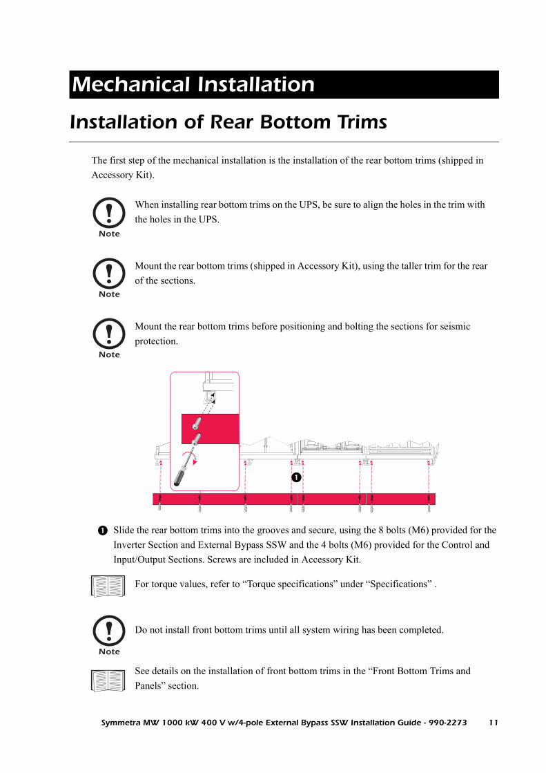
The first step of the mechanical installation is the installation of the rear bottom trims (shipped in Accessory Kit).
Slide the rear bottom trims into the grooves and secure, using the 8 bolts (M6) provided for the Inverter Section and External Bypass SSW and the 4 bolts (M6) provided for the Control and Input/Output Sections. Screws are included in Accessory Kit.
Note
When installing rear bottom trims on the UPS, be sure to align the holes in the trim with the holes in the UPS.
Note
Mount the rear bottom trims (shipped in Accessory Kit), using the taller trim for the rear of the sections.
Note
Mount the rear bottom trims before positioning and bolting the sections for seismic protection.
For torque values, refer to “Torque specifications” under “Specifications” .
Note
Do not install front bottom trims until all system wiring has been completed.
See details on the installation of front bottom trims in the “Front Bottom Trims and Panels” section.
Symmetra MW 1000 kW 400 V w/4-pole External Bypass SSW Installation Guide - 990-2273 11

Positioning the UPS Sections
All illustrated procedures show the Inverter Section being positioned first. The positioning sequence of the UPS sections is optional. Other solutions may be more practical under the given conditions. Other solutions involve rearrangements of the frame-joining brackets (see “Turning the frame-joining brackets” ).
Turning the frame-joining brackets
Loosen the bolts and nuts from the frame-joining bracket and remove.
Turn the frame-joining bracket and attach using the bolts and nuts from step 1.
Note
Before positioning the UPS sections in their final installation area, remove any finishing and dead front panels remaining on the system (as described in Appendix C).
If the system requires bolting to the floor for seismic protection, see “Seismic Anchoring” section before proceeding.
Note
Ensure that the open angle of the frame-joining bracket of the section positioned first is facing upwards, and that the open angle of the frame-joining bracket faces downwards on the neighbouring section so they can interlock.
12 Symmetra MW 1000 kW 400 V w/4-pole External Bypass SSW Installation Guide - 990-2273

Mechanical Installation: Positioning the UPS Sections
Positioning Configuration 1
Using a forklift, position the Inverter Section in its final position. Use level shims (in Accessory Kit shipped with unit) if required (illustration ).
Using a pallet jack or forklift, position and lower the Control Section. Allow the frame-joining bracket on the left foot of the Control Section to slide into the frame-joining bracket of the right foot of the Inverter Section (illustration ). Use level shims if necessary (illustration ).
Note
If the configuration includes an IP21 Drip Cover, proceed to the “IP21 Drip Cover (Option)” section before positioning and securing the system sections.
Use a pallet jack or a forklift for components over 54 kg.
Inverter Section Control Section
Level shims
11
Symmetra MW 1000 kW 400 V w/4-pole External Bypass SSW Installation Guide - 990-2273 13

Mechanical Installation: Positioning the UPS Sections
Using a pallet jack or forklift, position and lower the Input/Output Section. Allow the frame-joining bracket on the left foot of the Input/Output Section to slide into the frame-joining bracket of the right foot of the Control Section (illustration ). Use level shims if necessary (illustration ).
Input/Output Section
Level shims
14 Symmetra MW 1000 kW 400 V w/4-pole External Bypass SSW Installation Guide - 990-2273

Mechanical Installation: Positioning the UPS Sections
Symmetra MW 1000 kW 400 V w/4-pole External Bypass SSW Installation Guide - 990-2273 15
Positioning Configuration 2
On the right foot (front view) of the Inverter Section, loosen the bolts and nuts from the frame-
joining bracket and remove.
On the left foot (front view) of the Inverter Section, attach the frame-joining bracket as
illustrated.
On the left foot (front view) of the Input/Output Section, loosen bolts and nuts from the frame-
joining bracket and remove.
On the right foot (front view) of the Input/Output Section, attach the frame-joining bracket as
illustrated.
On the left foot (front view) of the Control Section, loosen the bolts and nuts, turn the frame-
joining and attach.
On the right foot (front view) of the Control Section, looseb the bolts and nuts, turn the frame-
joining and attach.
Note
If the configuration includes an IP21 Drip Cover, proceed to the “IP21 Drip Cover
(Option)” section before positioning and securing the system sections.
Inverter Section
Control Section
Input/Output Section
Mechanical Installation: Positioning the UPS Sections
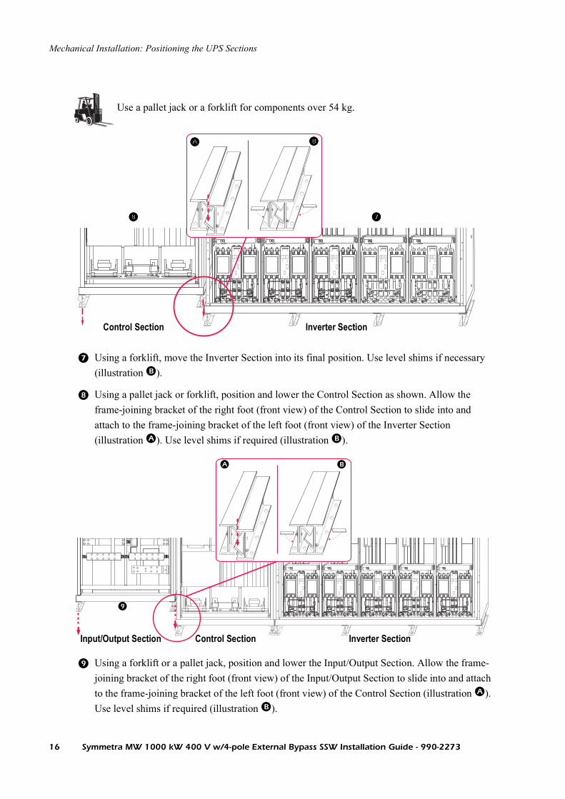
Using a forklift, move the Inverter Section into its final position. Use level shims if necessary (illustration ).
Using a pallet jack or forklift, position and lower the Control Section as shown. Allow the frame-joining bracket of the right foot (front view) of the Control Section to slide into and attach to the frame-joining bracket of the left foot (front view) of the Inverter Section (illustration ). Use level shims if required (illustration ).
Using a forklift or a pallet jack, position and lower the Input/Output Section. Allow the frame-joining bracket of the right foot (front view) of the Input/Output Section to slide into and attach to the frame-joining bracket of the left foot (front view) of the Control Section (illustration ). Use level shims if required (illustration ).
Use a pallet jack or a forklift for components over 54 kg.
Control Section Inverter Section
L3 In
Input/Output Section Control Section Inverter Section
16 Symmetra MW 1000 kW 400 V w/4-pole External Bypass SSW Installation Guide - 990-2273

Seismic Anchoring
Preparing for seismic anchoring
For seismic protection, anchor the UPS and External Bypass SSW configuration to the floor using the pre-drilled holes in the installation area.
See also
If holes have not been pre-drilled, refer to the drawings in the Site Preparation Guide.
Note
Applicable only to systems with an IP21 Drip Cover. If installing the UPS configuration against a wall, leave a gap of 30 mm between the configuration and the wall.
Note
Hole size for seismic protection = 15 mm.
Note
Mount rear bottom trims (shipped in Accessory Kit) before positioning and bolting the system for seismic protection.
Symmetra MW 1000 kW 400 V w/4-pole External Bypass SSW Installation Guide - 990-2273 17

Mechanical Installation: Seismic Anchoring
Seismic anchoring procedure
When seismic anchoring holes have been drilled, position the Inverter Section.
Secure the Inverter Section using washer and bolt. Do not fully tighten anchors at this stage.
Feet must be level. Use level shims (shipped in Accessory Kit) to level feet if necessary.
Follow the same procedure to position the Control and Input/Output Sections, and the External Bypass SSW.
When all sections are in place, make sure that they are straight and level.
Tighten anchors (refer to “Torque specifications” table under “Specifications” ).
Use a pallet jack or a forklift for components over 54 kg.
xHole size 15 mm
~~
Normal
UPS SummaryNormal
18 Symmetra MW 1000 kW 400 V w/4-pole External Bypass SSW Installation Guide - 990-2273

Interconnecting the UPS Sections
Temporary Removal of Main Static Switch
To gain access to the internal busbars for interconnecting the UPS Sections, the Main Static Switch (located in the Control Section in an independent frame) must be temporarily removed. Reinstallation is described later in this section.
From the top of the rear frame of the Main Static Switch, remove the 2 nuts on the studs attaching the module to the inside vertical framework of the Control Section. Remove the 4 bolts (2 at each side) attaching the module to the section framework. Put aside for reinstallation.
WARNING!Only qualified personnel may interconnect the UPS sections.
Top view
Front
Top view of Main Static Switch
Bolt
Symmetra MW 1000 kW 400 V w/4-pole External Bypass SSW Installation Guide - 990-2273 19

Mechanical Installation: Interconnecting the UPS Sections
Loosen the 4 screws in the cover plate at the top of the Main Static Switch and remove.
Loosen the 6 screws in the front cover plate at the bottom of the Main Static Switch and remove.
Remove busbars (shown in red) by removing screws (shown in red dotted circles). Put busbars aside for later reinstallation (see “Reinstallation of the Main Static Switch” ). *Remove busbar # 76 only if the Inverter is positioned to the right (Configuration 2).
Remove center bolt attaching midpoint cable to busbar bracket. Remove the two busbars # 47.
Remove busbar # 41.
Remove busbar # 54.
ON OFF EMO
L1 IN
L2 IN
64
7371
76*
70
65
65
74
# 54# 41
L2 OUT
L1 OUT
# 47# 47
20 Symmetra MW 1000 kW 400 V w/4-pole External Bypass SSW Installation Guide - 990-2273

Mechanical Installation: Interconnecting the UPS Sections
Disconnect X237.
Disconnect X320 from control box.
Disconnect X308 from control box.
Disconnect X328.
Disconnect patch cable.
~~
Normal
UPS SummaryNormal
L1 IN
L2 IN
L1 OUT
L2 OUT
Symmetra MW 1000 kW 400 V w/4-pole External Bypass SSW Installation Guide - 990-2273 21

Mechanical Installation: Interconnecting the UPS Sections
Position the ramp (shipped in Accessory Kit) on the pallet jack and adjust to height level with the bottom of the Control Section.Guide the 2 corner latches on the front of the ramp into the 2 holes in the frame. Have 2 people pull the Main Static Switch onto the ramp and remove.
Use a pallet jack or a forklift for components over 54 kg.
Two people to lift a component weighing between 18 - 32 kg.
22 Symmetra MW 1000 kW 400 V w/4-pole External Bypass SSW Installation Guide - 990-2273

Attachment of Rear Assembly Bracket
To connect two UPS sections, attach assembly brackets (shipped in Accessory Kit) to the top and bottom of each section as shown and secure using (4) M8 x 25 mm bolts included in Accessory Kit.
Left of (one) sectionRight of (one) section
252.5 mm
Front
195 mm
Symmetra MW 1000 kW 400 V w/4-pole External Bypass SSW Installation Guide - 990-2273 23

Attachment of Front Assembly Bracket
On the front of the sections, mount 2 brackets (shipped in Accessory Kit) as shown. Holes have been pre-punched along the sides from the top to bottom of the frame. Attach brackets using 10 bolts on each side of the bracket.
Normal0:00 AM
ON OFF EMO
Front Assembly Bracket
24 Symmetra MW 1000 kW 400 V w/4-pole External Bypass SSW Installation Guide - 990-2273

Busbars and Control Wires
This section specifies the connection of busbars and control wires between UPS sections.
WARNING!Only qualified personnel may make internal UPS connections.
Note
Follow the instructions provided for Configuration 1 if the Inverter Section is the left section in the installation.Follow the instructions provided for Configuration 2 if the Inverter Section is the right section in the installation.
Symmetra MW 1000 kW 400 V w/4-pole External Bypass SSW Installation Guide - 990-2273 25

Mechanical Installation: Busbars and Control Wires
Configuration I
Busbar connections between Inverter and Control Sections.
Overview of busbars to use (shipped in Accessory Kit) for the interconnection of the Inverter and Control Sections.
Connect L1 input from Inverter Section to L1 input in Control Section, using busbar #110.
Connect L1 output from Inverter Section to L1 output in Control Section, using busbar #110.
Connect L2 input from Inverter Section to L2 input in Control Section, using busbar #110.
Connect L2 output from Inverter Section to L2 output in Control Section, using busbar #110.
Connect L3 input from Inverter Section to L3 input in Control Section, using busbar #110.
L2 in
L2 out
L1 in
L1 out
L3 in
L3 out
DC+DC-
L1 IN
L1 OUT
L2 IN
L2 OUT
L3 IN
L3 OUT
Midpoint
BAT+ BAT-
Midpoint
BAT-
BAT+
110110110110
110
110110110
110 110
110 110 2 x 113 2 x 113
114114
6 x 110 2 x 113 1 x 114
Inverter Section Control Section
26 Symmetra MW 1000 kW 400 V w/4-pole External Bypass SSW Installation Guide - 990-2273

Mechanical Installation: Busbars and Control Wires
Connect L3 output from Inverter Section to L3 output in Control Section, using busbar #110.
Connect positive DC bus from Inverter Section to positive DC bus in Control Section, using busbar #114.
Connect negative DC bus from Inverter Section to negative DC bus in Control Section, using busbar #113.
Connect battery midpoint from Inverter Section to the battery midpoint in Control Section, using busbar #113.
Symmetra MW 1000 kW 400 V w/4-pole External Bypass SSW Installation Guide - 990-2273 27

Mechanical Installation: Busbars and Control Wires
Busbar connections between Control and Input/Output Sections.
Overview of busbars to use (shipped in Accessory Kit) for the interconnection of Control and Input/Output Sections.
Connect L1 output from Control Section to L1 output in Input/Output Section, using busbar #110.
Connect L2 output from Control Section to L2 output in Input/Output Section, using busbar #110.
Connect L3 output from Control Section to L3 output in Input/Output Section, using busbar #110.
Connect battery midpoint from Control Section to battery midpoint in Input/Output Section, using busbar #115.
Connect positive DC bus from Control Section to positive DC bus in Input/Output Section, using busbar #113.
Connect negative DC bus from Control Section to negative DC bus in Input/Output Section, using busbar #113.
BAT+
BAT+Midpoint
BAT+BAT-
BAT-
Midpoint
BAT-
L1 IN
L2 IN
L3 IN
L1 OUT
L2 OUT
L3 OUT
110
2 x 110
115
2 x 113
1 x 1153 x 110 2 x 113
Control Section Input/Output Section
28 Symmetra MW 1000 kW 400 V w/4-pole External Bypass SSW Installation Guide - 990-2273

Mechanical Installation: Busbars and Control Wires
Configuration II
Busbar connections between Control and Inverter Sections.
Overview of busbars to use (shipped in Accessory Kit) for the interconnection of the Control and Inverter Sections.
Connect L1 input from Inverter Section to L1 input in Control Section, using busbar #110.
Connect L1 output from Inverter Section to L1 output in Control Section, using busbar #110.
Connect L2 input from Inverter Section to L2 input in Control Section, using busbar #110.
Connect L2 output from Inverter Section to L2 output in Control Section, using busbar #110.
Connect L3 input from Inverter Section to L3 input in Control Section, using busbar #110.
Connect L3 output from Inverter Section to L3 output in Control Section, using busbar #110.
Connect positive DC bus from Inverter Section to positive DC bus in Control Section, using busbar #114.
L2 IN
BAT+BAT-DC-
Midpoint
110
110
110 110
110
1102 x 113
114
L1 IN
L3 IN
L1 OUT
L3 OUT
L2 OUT
L2 IN
6 x 110 2 x 113 1 x 114
Inverter SectionControl Section
Symmetra MW 1000 kW 400 V w/4-pole External Bypass SSW Installation Guide - 990-2273 29

Mechanical Installation: Busbars and Control Wires
Connect negative DC bus from Inverter Section to negative DC bus in Control Section, using busbar #113.
Connect battery midpoint from Inverter Section to battery midpoint in Control Section, using busbar #113.
Preparing the Input/Output Section for busbar connection to the Control Section
Remove EMC Board from unit.
Remove EMC brackets from busbars # 101, 102 and 103.
Unbolt and remove busbar # 120.
Unbolt and remove busbar # 103.
This unit contains components that are sensitive to electrostatic discharge (ESD). Follow proper ESD procedures to avoid severe damage to electronic components.
101
102
103
120
Spacer
Common Choke
Input/Output Section
30 Symmetra MW 1000 kW 400 V w/4-pole External Bypass SSW Installation Guide - 990-2273

Mechanical Installation: Busbars and Control Wires
Unbolt and remove busbar # 102.
Unbolt and remove busbar # 101.
Reinstall busbar # 120.
Refit EMC bracket onto busbar # 120.
Remove 6 spacers from busbar # 101, 102 and 103.
Busbars # 101, 102 and 103 are not to be reinstalled.
Busbar connections between Input/Output and Control Sections
Overview of busbars to use (shipped in Accessory Kit) for the interconnection of Input/Output and Control Sections.
BAT+
BAT+
BAT-
BAT-
BAT+
BAT- Battery Midpoint
Battery Midpoint
2 x 110
110
110
1 x 115
2 x 113
3 x 110 1 x 115 2 x 113
#60
L1 IN
L2 IN
L3 IN
L1 OUT
L2 OUT
L3 OUT
Control SectionInput/Output Section
Symmetra MW 1000 kW 400 V w/4-pole External Bypass SSW Installation Guide - 990-2273 31

Mechanical Installation: Busbars and Control Wires
Connect L1 output from Control Section to L1 output in Input/Output Section, using busbar #110.
Connect L2 output from Control Section to L2 output in Input/Output Section, using busbar #110.
Connect L3 output from Control Section to L3 output in Input/Output Section, using busbar #110.
Connect battery midpoint from Control Section to battery midpoint in Input/Output Section, using busbar #115.
Connect positive DC bus from Control Section to positive DC bus in Input/Output Section, using busbar #113.
Connect negative DC bus from Control Section to negative DC bus in Input/Output Section, using busbar #113.
Move busbar #60 from right side of battery midpoint to left side of battery midpoint.
32 Symmetra MW 1000 kW 400 V w/4-pole External Bypass SSW Installation Guide - 990-2273

Reinstallation of the Main Static Switch
Using a pallet jack, position the ramp carrying the Main Static Switch to the front of the Control Section.
Align ramp to bottom frame of Control Section. Guide the 2 corner latches on front of ramp into holes in frame of the Control Section. Have two people slide the Main Static Switch back into the Control Section.
Two people to lift a component weighing between 18 - 32 kg.
Use a pallet jack or a forklift for components over 54 kg.
1
Symmetra MW 1000 kW 400 V w/4-pole External Bypass SSW Installation Guide - 990-2273 33

Mechanical Installation: Reinstallation of the Main Static Switch
From the top of the rear of the Main Static Switch, reinstall the 2 nuts on the studs attaching the module to the inside vertical framework of the Control Section. Reinstall the 4 bolts (2 left, 2 right) and the 2 studs (1 left, 1 right) on the frame sides.
Top view of bolt connection.
Top view of Main Static Switch
Front
34 Symmetra MW 1000 kW 400 V w/4-pole External Bypass SSW Installation Guide - 990-2273

Mechanical Installation: Reinstallation of the Main Static Switch
Reinstall busbars # 71, 64, 65, and 74.
Reinstall center bolt attaching midpoint cable to busbar bracket. Reinstall the two# 47 busbars.
Reinstall busbar # 41.
Reinstall busbar # 54.
Reconnect X320.
Reconnect X308.
Reconnect X328.
Reconnect patch cable.
Reinstall cover plates. Attach top cover plate using 4 screws and bottom cover plate using the 6 screws.
ON OFF EMO
L3 IN
L3 OUT
# 64
# 71
# 65
# 74
# 47# 47
# 54# 41
L1 IN
L2 IN
L1 OUT
L2 OUT
Control Section
Symmetra MW 1000 kW 400 V w/4-pole External Bypass SSW Installation Guide - 990-2273 35

Busbar Connections after Reinstallation of Main Static Switch
Configuration 1
Busbar connections between Control and Input/Output Sections.
Overview of busbars to use (shipped in Accessory Kit) after the re-installation of the Main Static Switch in the Control Section.
Connect L1 input from Control Section to L1 input in Input/Output Section, using busbar #111
Connect L2 input from Control Section to L2 input in Input/Output Section, using busbar #110
Connect L3 input from Control Section to L3 input in Input/Output Section, using busbar #112
112110111
L1 IN
L1 IN
L2 IN
N
L2 IN
L3 IN
L1 OUT
L2 OUT
1 x 110 1 x 111
1 x 112
Control Section Input/Output Section
36 Symmetra MW 1000 kW 400 V w/4-pole External Bypass SSW Installation Guide - 990-2273

Mechanical Installation: Busbar Connections after Reinstallation of Main Static Switch
Configuration 2
Busbar connection between the Input/Output and Control Sections after reinstallation
of Main Static Switch.
Overview of busbars to use (shipped in Accessory Kit) for the interconnection of Input/Output and Control Sections.
Mount busbars # 101, 102 and 103 in common choke and common choke bracket.
Install insulators between busbars # 101, 102 and 103 where indicated.
Connect busbar # 101 to L1 input in the Input/Output Section.
L1 IN
L2 IN
BAT+
BAT+
BAT-
BAT-
Battery Midpoint BAT+
BAT-
L1 IN
L1 IN
L2 IN
L3 IN
N N
L3 IN
L1 OUT
L2 OUT
L3 OUT L2 IN
BatteryMidpoint
111
70
76 73
65
102 103
111
101116112
65
1 x 10³
1 x 101
1 x 10²
1 x 111
1 x 73
1 x 112
1 x 70
1 x 116
1 x 76
30 mm Isolator + M 8 bolt
30 mm Isolator + M 8 bolt
40 mm Isolator + M 8 bolt
Spacers
Control SectionInput/Output Section
Symmetra MW 1000 kW 400 V w/4-pole External Bypass SSW Installation Guide - 990-2273 37

Mechanical Installation: Busbar Connections after Reinstallation of Main Static Switch
Connect busbar # 102 to L2 input in the Input/Output Section.
Connect busbar # 103 to L3 input in the Input/Output Section.
Mount EMC brackets onto busbars # 101, 102 and 103 and reinstall EMC Board.
Connect busbar #70 to busbar #65 in the Control Section, installing insulators where indicated.
Connect busbar #73 to busbar #65 in the Control Section, installing insulators where indicated.
Connect busbar #76 to busbar #65 in the Control Section, installing insulators where indicated.
Connect busbar #111 to busbar #101 in the Input/Output Section and to busbar #70 in Control Section.
Connect busbar #116 to busbar #102 in the Input/Output Section and to busbar #73 in Control Section.
Connect busbar #112 to busbar #103 in the Input/Output Section and to busbar #76 in Control Section.Refit cover plates.
38 Symmetra MW 1000 kW 400 V w/4-pole External Bypass SSW Installation Guide - 990-2273

Connection of internal control wires
Connection of control wires between the Control Section and the Input/Output Section - Configuration 1
From the control board in the Control Section, connect control cable X205 (9-pin cable) to control connector X205 in the Input/Output Section.
From the Control Section connect control cable X206 (15-pin cable) to control connector X206 in the Input/Output Section.
Input/Output Section
Control Section
Control Board
Symmetra MW 1000 kW 400 V w/4-pole External Bypass SSW Installation Guide - 990-2273 39

Mechanical Installation: Connection of internal control wires
Connection of control wires between the Control Section and Input/Output Setion - Configuration 2
Fit mounting plate for AMP plugs (in Accessory Kit).
Use the longer of the two extensions for the control cables (in Accessory Kit) and connect cables X205 and X206 on the left hand side and cables X247 and X248 on the right hand side.
Use the shorter of the two extensions for the control cables (in Accessory Kit) and connect X247 and X248 on the left hand side and cables X205 and X206 on the right.
Reconnection of cable removed at temporary removal of Main Static Switch - Configuration 1 and 2
Reconnect cable joint X237.
Location of cable connections for cables X205 and X206.
~~
Normal
UPS SummaryNormal
L1 IN
L2 IN
L1 OUT
L2 OUT
x237
40 Symmetra MW 1000 kW 400 V w/4-pole External Bypass SSW Installation Guide - 990-2273

Mechanical Installation: Connection of internal control wires
Connection of communication cable between Control Section and Inverter Section - Configuration 1
From the top right Power Module in the Inverter Section, guide ribbon cable X305 into the Control Section and connect.
Use cable ties to attach cable. Use the cable tray at the left side of the Control Section.
Note
Make sure that the ribbon cables are properly installed.
L1 IN
L1 OUT
L2 IN
L2 OUT
~~
Normal
UPS SummaryNormal
X305
Inverter Section Control Section
Symmetra MW 1000 kW 400 V w/4-pole External Bypass SSW Installation Guide - 990-2273 41

Mechanical Installation: Connection of internal control wires
Connection of communication cable between Control Section and Inverter Section - Configuration 2
From the top left Power Module in the Inverter Section, guide ribbon cable X305 into the Control Section and connect.
Use cable ties to attach cable. Use the cable tray at the left side of the Control Section.
Note
Make sure that the ribbon cables are properly installed.
x305
~~
Normal
UPS SummaryNormal
L1 IN
L2 IN
L1 OUT
L2 OUT
Inverter SectionControl Section
42 Symmetra MW 1000 kW 400 V w/4-pole External Bypass SSW Installation Guide - 990-2273

Power Module Installation
The installation of the Power Modules is the last step of the mechanical installation.
Power Modules are shipped separately. Assemble and use crane to install Power Modules
Crane components
The following crane parts are shipped in Accessory Kit:
CAUTION!To protect the system against dust and debris, do not unpack the Power Modules before the mechanical installation is complete and the UPS is ready for start-up.
CAUTION!Follow this procedure carefully to avoid damaging the Power Modules and Inverter Sections.
Lockbars
Angle
Crane
Lifting profile
8 mm
Symmetra MW 1000 kW 400 V w/4-pole External Bypass SSW Installation Guide - 990-2273 43

Mechanical Installation: Power Module Installation
Crane assembly
Guide the 2 lockbars into the angle with the eye pointing forwards.
Insert the 2 lockbars in the 2 holes at the top of the Inverter Section frame in the appropriate section.
Attach the crane to the eye at the end of the angle.
Power Module installation procedure
Note
The crane can lift up to 150 kg.
CAUTION!Make sure that the lockbars are properly installed and that the lockbar plates touch the frame.
Inverter Section
356 mm
CAUTION!Only authorized people must install Power Modules. Be careful not to bump the module into the frame as this will damage the module.
44 Symmetra MW 1000 kW 400 V w/4-pole External Bypass SSW Installation Guide - 990-2273

Mechanical Installation: Power Module Installation
Use a forklift to transport the pallet containing the Power Module (56 kg) on pallet. Place the Power Module beneath the crane and attach the lifting profile to Power Module.
Connect the crane’s hook to the eye at the top of the lifting profile, and hoist the Power Module slightly above the tray on which it will be installed.
Position screw in unlocked position and pull out tray. Make sure that locking mechanism in both sides of the tray engages.
Lower the module and position it on the shelf in such a way that approx. 10 cm of the Power Module protrudes to the front of the tray.
Leaving the Power Module in its protuding position, remove the lifting profile.
Release the slide lock in both sides of the tray and push the tray with Power Module into the Inverter Section.
Note
The tray is locked when the screw is in horizontal position.
Tray
Symmetra MW 1000 kW 400 V w/4-pole External Bypass SSW Installation Guide - 990-2273 45

Mechanical Installation: Power Module Installation
With both hands, push the module in place so the front of the module flushes with the front of the tray.
Install the front bolt connecting module to tray.
Lock the module by turning the screw to the locked position.
Note
The tray is locked when the screw is in horizontal position.
Note
Do not install ribbon cables before the system is ready to start up.
46 Symmetra MW 1000 kW 400 V w/4-pole External Bypass SSW Installation Guide - 990-2273

Electrical Installation
Typical UPS Wiring
Power wiring overview
See also
See separate guide on parallel operation for wiring in parallel systems.
Mai
nten
ance
Byp
ass
Pan
el (
MB
P)
Sym
met
ra M
W
Ext
erna
l Byp
ass
Sta
tic S
witc
h
Bat
tery
Bre
aker
Box
1
Bat
tery
Bre
aker
Box
2
Bat
terie
s 1
Bat
terie
s 2
MA
INS
6
6
9 9
1. 2. 3. 4. 5. 6. 7.
8. 9. 10.
11.
12.
13.
14.
MA
INS
SO
UR
CE
3X
40
0/2
30
V T
N-S
(P
RO
VID
ED
BY
OT
HE
RS
).
Q1
-
Q6
WIT
H 2
NO
/2N
C A
UX
ILIA
RY
CO
NT
AC
TS
.
Q7
, Q
8 D
C R
AT
ED
TH
ER
MA
L M
AG
NE
TIC
TR
IP M
OL
DE
D C
AS
E C
IRC
UIT
BR
EA
KE
R.
WIT
H 2
4V
OL
T D
C U
ND
ER
VO
LT
AG
E R
EL
EA
SE
(U
VR
) A
ND
2N
O/2
NC
AU
XIL
IAR
Y C
ON
TA
CT
S.
AL
L A
C P
OW
ER
CA
BL
ING
IS
L1
,L2
,L3
,N,P
E.
UP
S I
NP
UT
AN
D O
UT
PU
T C
ON
DU
CT
OR
S M
US
T B
E I
N S
EP
AR
AT
E C
AB
LE
RU
NS
.
UP
S A
ND
ST
AT
IC B
YP
AS
S W
ITH
ST
AN
D R
AT
ING
, Ic
w =
20
0 K
A
SE
E T
HE
IN
ST
AL
LA
TIO
N G
UID
E F
OR
TH
E B
RE
AK
ER
SE
TT
ING
S O
F Q
1,
Q3
, Q
4 A
ND
Q5
.
DC
CA
BL
ING
SH
OU
LD
BE
SE
GR
EG
AT
ED
FR
OM
AC
CA
BL
ING
SE
E B
AT
TE
RY
IN
ST
AL
LA
TIO
N I
NF
OR
MA
TIO
N
PO
WE
R W
IRIN
G A
ND
CO
NT
RO
L W
IRIN
G M
US
T B
E S
EG
RE
GA
TE
D.
AC
CIR
CU
IT C
AB
LE
LE
NG
TH
S (
INP
UT
AN
D O
UT
PU
T)
SH
OU
LD
BE
EQ
UA
L O
N A
LL
MO
DU
LE
S
DC
CIR
CU
IT C
AB
LE
LE
NG
TH
S S
HO
UL
D B
E E
QU
AL
ON
AL
L M
OD
UL
ES
= C
AB
LIN
G P
RO
VID
ED
BY
OT
HE
RS
INS
TA
LL
AT
ION
MU
ST
CO
MP
LY
WIT
H N
AT
ION
AL
AN
D L
OC
AL
EL
EC
TR
ICA
L R
UL
ES
.
Symmetra MW 1000 kW 400 V w/4-pole External Bypass SSW Installation Guide - 990-2273 47

External Disconnection SwitchesWARNING!The UPS has no built-in manual disconnect devices to switch off external AC (Q1 and Q5) and DC (Q7 and Q8) input power. Ensure that disconnection devices are available as separate components for this installation.
Note
The installer must provide each external disconnection device for this UPS system with labels displaying the following text:“Isolate the Uninterruptible Power Supply (UPS) as instructed in the User Guide before working on circuit.”
48 Symmetra MW 1000 kW 400 V w/4-pole External Bypass SSW Installation Guide - 990-2273

Input/Output Wiring Precautions
WARNING!Only personnel trained in the construction and operation of the equipment, and the electrical and mechanical hazards involved, may install or remove system components.
WARNING!Before installation or maintenance work is carried out, shut off the UPS and External Bypass SSW and disconnect all AC and DC power sources. Wait 5 minutes until all capacitor banks are discharged.
WARNING!Supply the UPS from a 3 × 400/230 V, L1, L2, L3, N, PE source or a high-impedance grounded system.
CAUTION!All wiring to be in accordance with applicable national and/or local electrical wiring rules.
Note
Use only copper conductors.
Symmetra MW 1000 kW 400 V w/4-pole External Bypass SSW Installation Guide - 990-2273 49

Preparing for Top Cable Entry (Default)
Cable entry in Top Cover of Input/Output Section:
Loosen the 8 bolts in both cable entry covers (4 bolts in each cover). Drill holes for grommets in areas shown. Install grommets. Refit covers.
Install cable lugs on busbars. Use M12 bolts. Feed cables through top grommets.
Connect L1, L2 and L3 to busbars where indicated.
Note
No drilling or cutting should take place over the top of the UPS.
NN
L2 IN
L1 IN
L3 IN
L1 OUT
L2 OUT
L3 OUT
AC IN AC OUT
BAT 1 BAT 2
92 93
9590
91 94
L3 OUT
L2 OUT
92 93
90
91 94
95
L1 OUT
L3 IN
L2 IN
L1 IN
58 mm
44.45 mm44.45 mm
IN/OUT power cable (top entry)
AC IN cable entry
AC OUT cable entry
BAT cable entry
BAT cable entry
Top viewM6 Bolt
Top view
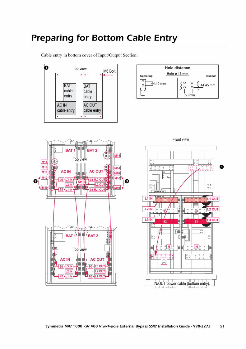
Preparing for Bottom Cable Entry
Cable entry in bottom cover of Input/Output Section:
AC IN AC OUT
N N
AC IN AC OUT
BAT 1 BAT 2
BAT 1 BAT 2
M14
M14
90 95
9392
91 94
M14
M14
M10
M10
M10M10
M10
M10
M10
L1 OUT
L2 OUT
L3 OUT
L1 IN
L2 IN
L3 IN
L3 OUT
L2 OUT
95
93 L1 OUT
L3 OUT
L2 OUT
95
93 L1 OUT
L3 IN
L2 IN
L1 IN
90
92
L3 IN
L2 IN
L1 IN
90
92
AC IN cable entry
AC OUT cable entry
BAT cable entry
BAT cable entry
IN/OUT power cable (bottom entry).
Top view
Top view
Top view M6 Bolt
58 mm
44.45 mm44.45 mm
Front view
Symmetra MW 1000 kW 400 V w/4-pole External Bypass SSW Installation Guide - 990-2273 51

Electrical Installation: Preparing for Bottom Cable Entry
Preparation for bottom cable entry
a. Loosen bolts of both cable entry covers and remove.
b. Drill holes for grommets for AC, DC, and Output circuit grounding electrode cable in areas shown.
c. Install grommets.
d. Remount covers.
Interchange of AC IN busbars for bottom entry
a. Remove nuts from M14 bolts at busbars 90 and 92.
b. Remove bolt, washer and fuse.
c. Remove bolts from M10 at busbars 90 and 92.
d. Remove busbars 90 and 92 at AC IN.
e. Move the two front isolators in the topmost busbar position two steps to the front.
f. Move the two front isolators in the lowest busbar position two steps to the rear.
g. Install busbar 90 in original position of busbar 92.
h. Install busbar 92 in original position of busbar 90.
i. Reattach M14 bolts at busbars 90 and 92.
j. Install cable lugs on busbars using M12 bolts.
Interchange of AC OUT busbars for bottom entry
a. Remove nuts from M14 bolts at busbars 93 and 95.
b. Remove bolt, washer and fuse.
c. Remove bolts from M10 at busbars 93 and 95.
d. Remove busbars 93 and 95 at AC OUT.
e. Move the two front isolators in the topmost busbar position two steps to the front.
f. Move the two front isolators in the lowest busbar position two steps to the rear.
g. Install busbar 93 in original position of busbar 95.
h. Install busbar 95 in original position of busbar 93.
i. Reattach M14 bolts at busbars 93 and 95.
j. Install cable lugs on busbars using M12 bolts.
Moving busbar for grounding
a. Move busbar for grounding from upper right corner to lower left corner as illustrated.
Note
No drilling or cutting should take place inside the UPS.
52 Symmetra MW 1000 kW 400 V w/4-pole External Bypass SSW Installation Guide - 990-2273

Battery Cable Connection (Top and Bottom Cable Entry)
WARNING!Make sure that the battery breakers are open (OFF) prior to running the cables.
CAUTION!For battery installation and maintenance instructions, refer to the battery manufacturer’s installation manual.
CAUTION!The minimum DC voltage rating of the battery supply over-current protective device is 500 V.
Note
Over-current protection for the battery circuit is required by national wiring rules.
Symmetra MW 1000 kW 400 V w/4-pole External Bypass SSW Installation Guide - 990-2273 53

Electrical Installation: Battery Cable Connection (Top and Bottom Cable Entry)
Connecting battery cables to Input/Output Section (top cable entry)
Connect cables from battery system as illustrated.
Connect cables from battery system as illustrated.
BAT1+
BAT2-
L3 In
L2 In
L1 In
L2 Out
L3 Out
L1 Out
BAT1-
BAT1+
BAT2+
BAT2—
N N
BAT1- BAT2+
IN/OUT power cable (top entry)
Top view of Input/Output Section
Battery 1(BAT 1 +/-)
Battery 2(BAT 2 +/-)
Input/Output Section
AC IN cable entry
AC OUT cable entry
M6 Bolt
58 mm
44.45 mm44.45 mm
Battery cable entry
Battery cable entry
54 Symmetra MW 1000 kW 400 V w/4-pole External Bypass SSW Installation Guide - 990-2273

Electrical Installation: Battery Cable Connection (Top and Bottom Cable Entry)
Connecting battery cables to Input/Output Section (bottom cable entry)
Connect cables from battery system as illustrated.
Connect cables from battery system as illustrated.
BAT1+
BAT2-
BAT1- BAT2+
L3 In
L2 In
L1 In
L2 Out
L3 Out
L1 Out
BAT1-
BAT1+
BAT 2+
BAT2—
N N
58 mm
44.45 mm44.45 mm
IN/OUT power cable (bottom entry)
Bottom cover of Input/Output Section
Battery 1(BAT 1 +/-)
Battery 2(BAT 2 +/-)
AC IN cable entry
AC OUT cable entry
Battery cable entry
M6 Bolt
Battery cable entry
Input/Output Section
Symmetra MW 1000 kW 400 V w/4-pole External Bypass SSW Installation Guide - 990-2273 55

PE and AC Cable Connection
Connecting PE and AC cables to Input/Output Section (top cable entry)
Feed AC and ground cables through top of Input/Output Section as illustrated.
Connect cables as illustrated.
NNProtective Earthing conductors (red) for Battery 1 & AC IN
Protective Earthing conductors (red) for Battery 2 & AC OUT
Battery 2
Battery 1
Earthing conductor connected to suitable earth electrode TN-systems
Output circuit grounding bar
PE
58 mm
44.45 mm44.45 mm
Bonding Jumper (TN-systems) to Input Neutral Bar
Input/Output Section
56 Symmetra MW 1000 kW 400 V w/4-pole External Bypass SSW Installation Guide - 990-2273

Electrical Installation: PE and AC Cable Connection
Connecting PE and AC cables to Input/Output Section (bottom cable entry)
Feed AC and ground cables through bottom of Input/Output Section as illustrated.
Connect cables as illustrated.
NN
Protective Earthing Conductors for Battery 1 & AC IN
Protective Earthing Conductors for Battery 2 & AC OUT
Battery 2
Battery 1
Output circuit grounding bar
Earthing conductor connected to suitable earth electrode TN-systems
Output circuit grounding bar
58 mm
44.45 mm44.45 mm
PE
Bonding Jumber (TN-systems) to Input Neutral Bar
Input/Output Section
Symmetra MW 1000 kW 400 V w/4-pole External Bypass SSW Installation Guide - 990-2273 57


External Bypass Static Switch Wiring
WARNING!Before installation or maintenance work is carried out, shut off the UPS and External Bypass SSW and disconnect all AC and DC power sources. Wait 5 minutes until all capacitor banks are discharged.
WARNING!Use only manual reset protection as input over-current protection.
WARNING!Over-current protection required by national wiring rules.
WARNING!The UPS has no built-in manual disconnect devices to switch off external AC (Q1 and Q5) and DC (Q7 and Q8) input power. Ensure that disconnection devices are available as separate components for this installation.
CAUTION!The External Bypass Static Switch is not provided with built-in backfeed protection. Use suitable breakers with a minimum of 0.8 in/20 mm air gap and trip function. The breaker is controlled from the External Bypass SSW and will be tripped in case of backfeed.
Note
The installer must provide each external disconnection device for this UPS system with labels displaying the following text:“Isolate the Uninterruptible Power Supply (UPS) as instructed in the User Guide before working on circuit.”
Note
The installation of the External Bypass Static Switch must comply with local and national regulations.
Note
Run matched set of phase cables in the same cable run(s).Do not separate phases into different cable runs.
Note
Use only copper conductors.
Symmetra MW 1000 kW 400 V w/4-pole External Bypass SSW Installation Guide - 990-2273 59

Top Cable Entry
Loosen the 8 screws to remove top covers. Drill holes for grommets. Refit covers. Install grommets.
Feed cables through grommets. Connect cables at cable connection points as indicated.
Connect grounding electrode conductor to busbar locations as shown.
~~
Normal
UPS SummaryNormal
X022
X021
X007
X010
X011
X008B
X008A
X012
X013
X014A
X014B
X017
X40
5
L1
IN
L2
IN
L3
IN
L1
OUT
L2
OUT
L3
OUT
IN N
OUT
N
L3 IN
L3 OUT
IN N
OUT N
L2 IN
L2 OUT
L1 IN
L1 OUT
58 mm
44.45 mm44.45 mm
Top view of top cover
Top view of AC IN & OUT cable connections
External Bypass SSW
Note
No drilling or cutting should take place over the top of the External Bypass SSW.
60 Symmetra MW 1000 kW 400 V w/4-pole External Bypass SSW Installation Guide - 990-2273

Communication Cables
The connection planes in the UPS Control Section and External Bypass SSW are the communication interface between UPS, External Bypass SSW, and the CAN boards mounted in the Maintenance Bypass Panel (MBP) and the Battery Breaker Box.WARNING!All signal and control wiring must be separated from high-power wiring.
Symmetra MW 1000 kW 400 V w/4-pole External Bypass SSW Installation Guide - 990-2273 61

Feeding Communication Cables into UPS and External Bypass SSW
Unbolt communication cable cover in the Control and External Bypass SSW Sections. Drill/punch holes in as large an area as necessary in the covers. Use grommets to feed cables through punched holes.
In the Control Section, route the communication cables through the cable trays provided at the top and along the side to the connection plane as illustrated.
Follow the connection procedures in “Communication Cables between UPS and External Bypass SSW” and “Communication Cables between UPS System and Ancillary Equipment” .
Note
No drilling or cutting should take place over the top of the UPS.
~~
Normal
UPS SummaryNormal
X022
X021
X007
X010
X011
X008B
X008A
X012
X013
X014A
X014B
X017
X40
5
~~
Normal
UPS SummaryNormal
X012 X013
X103X104
Backfeed protectionEpo OutEpo Out
X131 X132
Ext. Epo Sup Epo Switch
X185 X177 X128 X129
X133A CAN IO Battery
X134A CAN IO MBP
X135
K1
V1
Display
Par
alle
l bu
s 2
X12
7B
X12
7A
X126B
X126A
Parallel b
us 1
X126B
X126A
Int. Ext.
CONNECTION PLANE ASSY NO: 640-4607A Rev.02 2004 APC
EPO
Connection plane
Communication cables
Control Section External Bypass SSWEPO cable connection
Port for Communication cables
62 Symmetra MW 1000 kW 400 V w/4-pole External Bypass SSW Installation Guide - 990-2273

Communication Cables between UPS and External Bypass SSW
Interconnect the sections using the provided cables.
X012 X013
X103X104
Backfeed protectionEpo OutEpo Out
X131 X132
Ext. Epo Sup Epo Switch
X185 X177 X128 X129
X133A CAN IO Battery
X134A CAN IO MBP
X135
K1
V1
Display
Par
alle
l bu
s 2
X12
7B
X12
7A
X126B
X126A
Parallel b
us 1
X126B
X126A
X126B
X126A
Int. Ext.
CONNECTION PLANE ASSY NO: 640-4607A Rev.02
X126B X126A X127A X127B X126B X126AX127BX127A
2004 APC2004 APC
External Bypass Static Switch Control Section
Connect X126B from the Control Section to X126A in the External Bypass SSW.Connect X127B from the Control Section to X127A in the External Bypass SSW.In the Control Section, connect terminator 0M-1879 to X126A.In the Control Section, connect terminator 0M-1880 to X127A.In the External Bypass SSW, connect terminator 0M-1879 to X126B.In the External Bypass SSW, connect terminator 0M-1880 to X127B.
Symmetra MW 1000 kW 400 V w/4-pole External Bypass SSW Installation Guide - 990-2273 63

Communication Cables between UPS System and Ancillary Equipment
Follow the procedure below to connect communication cables between UPS system and Ancillary Equipment.
Note
Some of the steps are only applicable to installations with non-APC ancillary equipment.
See also
See separate Parallel System guide for information on communication cables in parallel systems.

Communication Cables: Communication Cables between UPS System and Ancillary Equipment
Communication cable overview
Con
nect
ion
plan
e0P
4627
X131
X130
ExternalEPO
placed inroom
X133A 21X185
UPS
EM
O (
Dis
play
)
X134A
X1281
1 2
2
X1291
2
Bac
kfee
d pr
otec
tion
EPO out
EPO out
Con
nect
ion
plan
e0P
4627
External Bypass Static Switch
X128
X12
6A
X12
7A
X129
X131
X130
1
2
1
2
Bac
k fe
ed1
Bac
k fe
ed2
EM
O (
Dis
play
)
X134A
MBP CAN I/O board1
Maintenance Bypass Panel
Maintenance Bypass Panel
0P4533A
C2
43
C1
21
X17
8
61
23
45
X17
3M
BP
Bre
aker
s
X17
6
87
109
1211
X134A
X134B
Terminator0M-1878A
56
Q2
34
12
Q1
X1771
2X177
1
2
X1771
2
X134A
X1281
2
X129
710
11
X17
3
MB
PB
reak
ers
X172Lamps
H6
109
H5
87
H4
65
H3
43 3 41 2
Q5
X176
11 1221
C2
43
C1
21
X17
8
X175
12
Norm.op
Relay output
X174
12
Earth fault sensor
5 6
Q6
Q6
X1771
2
Q5
912
Q4
8
Q3
65
43
21
Q1
21
X175
12
Norm.op
Relay output
X174
12
Earth fault sensor
X172Lamps
X128
12
X129
12
MBP CAN I/O board 20P4533A
4321 121187 10965
X134B
Terminator0M-1878A
Q2
+
-
External Lampsupply V or VMax. 250V 5A
+ - + - + - + -
24VShunt trip forback feedprotection
+
-
-+
+
-
+-
+
-
+
-
-
+
+ - + - + -
24V
Shunt trip
X12
6B
X12
7B
X12
6B
X12
7B
X12
6A
X12
7A
1 42 3X170
1 42 3X170
X186
34
1 2 3 4X182
1 2 3X183
X133A
Battery CAN I/O boardID 1
0P4512A
4
12X
184X
180
14
23
Fuse
5
1 2 3 4
Fuse
6
5 6
Fuse
7
7 8
Fuse
8
X133BTerminator0M-1878A
Battery Breaker Box
12
X185
X186
Q7
1 2 3 4
Q8
X182
X133A
12
X185
Battery CAN I/O boardID 0
0P4512A
X18
01
42
3
X133B
Fuse
1
1 2
Fuse
2
3 4
Fuse
3
5 6
Fuse
4
7 8
1 2 3X183
H7
H8
4
+ - + -
31
Temp sensor+
+
42 -X18
1
Temp sensor
NTC
NTC-
31
Q8
Q7
UVR+
+
42
UVR
-
-
X18
4
DC
DC
DC DC
AC
Note 1
Note 1
Note 3
Note 2
Note 3
Note 1: Contact APC Application Team for correct sizing.Note 2: H7, H8 = 5V LEDNote 3: Q2, Q4 and Q6 are optional. If Q2 is not present pins 3 and 4 must be shorted on both boards. If Q4 is not present pins 7 and 8 must be shorted on both boards. If Q6 is not present pins 11 and 12 must be shorted on both boards.
Symmetra MW 1000 kW 400 V w/4-pole External Bypass SSW Installation Guide - 990-2273 65

Communication Cables: Communication Cables between UPS System and Ancillary Equipment
Communication cables between UPS and Battery CAN I/O Board ID 0 in Battery Breaker Box
Steps only applicable to UPS systems with non-APC ancillary equipment.
Connect X133A from the UPS to X133A on Battery CAN I/O Board ID 0.Connect X185 from the UPS to X185 on Battery CAN I/O Board ID 0.Connect temperature sensors provided with the Battery Breaker Box to X181.
On Battery CAN I/O Board ID 0, connect X182, pin 1, 2 to Q7 auxillary contact.On Battery CAN I/O Board ID 0, connect X182, pin 3, 4 to Q8 auxillary contact.On Battery CAN I/O Board ID 0, connect X183, pin 1, 2 to H7.On Battery CAN I/O Board ID 0, connect X183, pin 3, 4 to H8.On Battery CAN I/O Board ID 0, connect X184, pin 1, 2 to UVR Q7 (relay for tripping of Q7 in non-APC Battery Enclosure).
On Battery CAN I/O Board ID 0, connect X184, pin 3, 4 to UVR Q8 (relay for tripping of Q8 in non-APC Battery Enclosure).On Battery CAN I/O Board ID 0, connect X186, pin 1, 2 to fuse indicator 1 on battery string (if available - if not connect jumper).On Battery CAN I/O Board ID 0, connect X186, pin 3, 4 to fuse indicator 2 on battery string (if available - if not connect jumper).
Con
nect
ion
plan
e0P
4627
X131
X130
X133A 21X185
UPS
EM
O (
Dis
play
)
X134A
X1281
1 2
2
X1291
2
Bac
kfee
d pr
otec
tion
EPO out
EPO out
X1771
2X
126B
X12
7BX
126A
X12
7A
X186
34
1 2 3 4X182
1 2 3X183
X133A
Battery CAN I/O boardID 1
0P4512
4
12X
184X
180
14
23
Fuse
5
1 2 3 4
Fuse
6
5 6
Fuse
7
7 8
Fuse
8
X133BTerminator0M-1878A
Battery Breaker Box
12
X185
X186
Q7
1 2 3 4
Q8
X182
X133A
12
X185
Battery CAN I/O boardID 0
0P4512X
180
14
23
X133BFu
se1
1 2
Fuse
2
3 4
Fuse
3
5 6
Fuse
4
7 8
1 2 3X183
H7
H8
4
+ - + -
31
Temp sensor+
+
42 -X18
1
Temp sensor
NTC
NTC-
31
Q8
Q7
UVR+
+
42
UVR
-
-
X18
4
ExternalEPO
placed onwall
66 Symmetra MW 1000 kW 400 V w/4-pole External Bypass SSW Installation Guide - 990-2273

Communication Cables: Communication Cables between UPS System and Ancillary Equipment
Communication cables between Battery CAN I/O Board ID 0 and Battery CAN I/O Board ID 1 in Battery Breaker Box (if available)
Steps only applicable to UPS systems with non-APC ancillary equipment.
On Battery CAN I/O Board ID 0, connect X186, pin 5, 6 to fuse indicator 3 on battery string (if available - if not connect jumper).On Battery CAN I/O Board ID 0, connect X186, pin 7, 8 to fuse indicator 4 on battery string (if available - if not connect jumper).
Connect X133B from Battery CAN I/O Board ID 0 to X133A on Battery CAN I/O Board ID 1.On Battery CAN I/O Board ID 1, connect terminator 0M-1878A to X133B.On Battery CAN I/O Board ID 1, connect jumper from X180, pin 1 to X180, pin 2.
X186
34
1 2 3 4X182
1 2 3X183
X133A
Battery CAN I/O boardID 1
0P4512
41
2X18
4X18
01
42
3
Fuse
5
1 2 3 4
Fuse
6
5 6
Fuse
7
7 8
Fuse
8
X133BTerminator0M-1878A
Battery Breaker Box
12
X185
X186Q
7
1 2 3 4
Q8
X182
X133A
12
X185
Battery CAN I/O boardID 0
0P4512
X18
01
42
3
X133B
Fuse
11 2
Fuse
23 4
Fuse
3
5 6
Fuse
4
7 8
1 2 3X183
H7
H8
4
+ - + -
31
Temp sensor+
+
42 -X18
1
Temp sensor
NTC
NTC-
31
Q8
Q7
UVR+
+
42
UVR
-
-
X18
4
On Battery CAN I/O Board ID 1, connect X186, pin 1, 2 to fuse indicator 5 on battery string (if available - if not connect jumper).On Battery CAN I/O Board ID 1, connect X186, pin 3, 4 to fuse indicator 6 on battery string (if available - if not connect jumper).On Battery CAN I/O Board ID 1, connect X186, pin 5, 6 to fuse indicator 7 on battery string (if available - if not connect jumper).On Battery CAN I/O Board ID 1, connect X186, pin 7, 8 to fuse indicator 8 on battery string (if available - if not connect jumper).
Symmetra MW 1000 kW 400 V w/4-pole External Bypass SSW Installation Guide - 990-2273 67

Communication Cables: Communication Cables between UPS System and Ancillary Equipment
Communication cables between UPS and External EPO
Connect X131 to External EPO on wall (use contact I as specified on diagram).
Con
nect
ion
plan
e0P
4627
X131
X130
ExternalEPO
placed inroom
X133A 21X185
UPS
EM
O (
Dis
play
)
X134A
X1281
1 2
2
X1291
2
Bac
kfee
d pr
otec
tion
EPO out
EPO out
X1771
2
X12
6B
X12
7BX
126A
X12
7A
68 Symmetra MW 1000 kW 400 V w/4-pole External Bypass SSW Installation Guide - 990-2273

Communication Cables: Communication Cables between UPS System and Ancillary Equipment
Communication cables between UPS and MBP CAN I/O Board 1 in Maintenance Bypass Panel (MBP)
Steps only applicable to UPS systems with non-APC ancillary equipment.
Connect X134A from the UPS to X134A on MBP CAN I/O Board 1. In installations with optional Relay Board refer to Connecting Optional Relay Board section.Connect X177 from the UPS to X177 on MBP CAN I/O Board 1.On MBP CAN I/O Board 1, connect terminator 0M-1878A to X134B.
Con
nect
ion
plan
e0P
4627
X131
X130
ExternalEPO
placed inroom
X133A 21X185
UPS
EM
O (
Dis
play
)
X134A
X1281
1 2
2
X1291
2
Bac
kfee
d pr
otec
tion
EPO out
EPO out
MBP CAN I/O board1
Maintenance Bypass Panel
0P4533A
C2
43
C1
21
X17
8
61
23
45
X17
3M
BP
Bre
aker
s
X17
6
87
109
1211
X134A
X134B
Terminator0M-1878A
56
Q2
34
12
Q1
X1771
2X177
1
2
H4H3
Q6
Q5
Q4
Q3
Q1
X175
12
Norm.op
Relay output
X174
12
Earth fault sensor
X172Lamps
X128
12
X129
12
4321 121187 10965
Q2
+ - + -
+
-
+-
+
-
+
-
-
+
24V
Shunt trip
X12
6B
X12
7BX
126A
X12
7A
1 42 3X170
+
-
External Lampsupply V or VMax. 250V 5A
DC
DC
AC
AC
On MBP CAN I/O Board 1, connect X172, pin 3, 4 to H3 lamp.On MBP CAN I/O Board 1, connect X172, pin 5, 6 to H4 lamp.On MBP CAN I/O Board 1, connect X172, pin 11, 12 to external supply for lamp.On MBP CAN I/O Board 1, connect X173, pin 1, 2 to Q1 breaker indicator(contact I).On MBP CAN I/O Board 1, at X173, connect pin 3, 4 to Q2 breaker indicator (contact I). If Q2 is not available, connect jumper between pin 3 and 4.On MBP CAN I/O Board 1, connect X173, pin 5, 6 to Q3 breaker indicator (contact I).
On MBP CAN I/O Board 1, connect X173, pin 7, 8 to Q4 breaker indicator (contact I).If Q4 is not available, connect jumper between pin 7 and 8.On MBP CAN I/O Board 1, connect X173, pin 9, 10 to Q5 breaker indicator (contact I).
Symmetra MW 1000 kW 400 V w/4-pole External Bypass SSW Installation Guide - 990-2273 69

Communication Cables: Communication Cables between UPS System and Ancillary Equipment
On MBP CAN I/O Board 1, connect X173, pin 11, 12 to Q6 breaker indicator (contact I). If Q6 is not available, connect jumper between pin 11 and 12.
On MBP CAN I/O Board 1, connect X174, pin 1, 2 to earth fault indicator (if available - if not, connect jumper).Optional: On MBP CAN I/O Board 1, connect X175, normal operation output indicator.On MBP CAN I/O Board 1, connect X176 pin 1, 2 to shunt trip breaker Q1.On MBP CAN I/O Board 1, connect X176 pin 3, 4 to shunt trip breaker Q1 (3, 4 redundant with 1, 2).On MBP CAN I/O Board 1, connect X176 pin 5, 6 to shunt trip breaker Q2 (if available).On MBP CAN I/O Board 1, connect X178, pin 1, 2 to shunt trip capacitor C1 (Contact APC Application Team for correct sizing).On MBP CAN I/O Board 1, connect X178, pin 3, 4 to shunt trip capacitor C2 (Contact APC Application Team for correct sizing).
70 Symmetra MW 1000 kW 400 V w/4-pole External Bypass SSW Installation Guide - 990-2273

Communication Cables: Communication Cables between UPS System and Ancillary Equipment
Communication cables between MBP CAN I/O Boards 1 and 2 (only applicable for installations with non-APC Ancillary Equipment)
On MBP CAN I/O Board 2, connect X172, pin 3, 4 to H3 lamp.On MBP CAN I/O Board 2, connect X172, pin 5, 6 to H4 lamp.On MBP CAN I/O Board 2, connect X172, pin 7, 8 to H5 lamp.On MBP CAN I/O Board 2, connect X172, pin 9, 10 to H6 lamp.On MBP CAN I/O Board 2, connect X173, pin 1, 2 to Q1 breaker indicator (contact II).On MBP CAN I/O Board 2, at X173 connect pin 3, 4 to Q2 breaker indicator (contact II). If Q2 is not available, connect jumper between pin 3 and 4.On MBP CAN I/O Board 2, connect X173 pin, 5, 6 to Q3 (contact II).On MBP CAN I/O Board 2, connect X173 pin, 7, 8 to Q4 (contact II). If Q4 is not available, connect jumper between pin 7 and 8.On MBP CAN I/O Board 2, connect X173 pin, 9, 10 to Q5 (contact II).On MBP CAN I/O Board 2, connect X173 pin, 11, 12 to Q6 (contact II). If Q6 is not available, connect jumper between pin 11 and 12.On MBP CAN I/O Board 2, connect X174, pin 1, 2 to earth fault indicator (if available - if not, connect jumper).Optional: On MBP CAN I/O Board 2, connect X175, normal operation output indicator.On MBP CAN I/O Board 2, connect X176, pin 1, 2 to shunt trip breaker Q5.On MBP CAN I/O Board 2, connect X176, pin 3, 4 to shunt trip breaker Q5 (3, 4 redundant with 1, 2).On MBP CAN I/O Board 2, connect X176, pin 5, 6 to shunt trip breaker Q6.On MBP CAN I/O Board 2, connect X178, pin 1, 2 to shunt trip capacitor C1 (Contact APC Application Team for correct sizing).
Maintenance Bypass Panel
X1771
2
X134A
X1281
2
X129
710
11
X17
3
MB
PB
reak
ers
X172Lamps
H6
109
H5
87
H4
65
H3
43 3 41 2
Q5
X176
11 1221
C2
43
C1
21
X17
8
X175
12
Norm.op
Relay output
X174
12
Earth fault sensor
5 6
Q6
Q6
Q5
912
Q4
8
Q3
65
43
21
Q1
21
MBP CAN I/O board 20P4533A
X134B
Terminator0M-1878A
Q2
+
-
+ - + - + - + -
Shunt trip forback feedprotection
+
-
-+
+ - + - + -
1 42 3X170
24V
External Lampsupply V or VMax. 250V 5A
DC
DC
AC
AC
Symmetra MW 1000 kW 400 V w/4-pole External Bypass SSW Installation Guide - 990-2273 71

Communication Cables: Communication Cables between UPS System and Ancillary Equipment
Communication cables between External Bypass SSW and MBP CAN I/O Board 2
On MBP CAN I/O Board 2, connect X178, pin 3, 4 to shunt trip capacitor C2 (Contact APC Application Team for correct sizing).Connect terminator 0M-1878A to X134B on MBP CAN I/O Board 2.
Connect X134A from the External Bypass SSW to X134A on MBP CAN I/O Board 2.Connect X177 from the External Bypass SSW to X177 on MBP CAN I/O Board 2.Connect X128 from the External Bypass SSW to X128 on MBP CAN I/O Board 2.Connect X129 from the External Bypass SSW to X129 on MBP CAN I/O Board 2.On MBP CAN I/O Board 2, connect terminator 0M-1878A to X134B.
Con
nect
ion
plan
e0P
4627
External Bypass Static Switch
X128
X12
6A
X12
7A
X129
X131
X130
1
2
1
2
Bac
k fe
ed1
Bac
k fe
ed2
EM
O (
Dis
play
)
X134A
Maintenance Bypass Panel
X1771
2
X134A
X1281
2
X129
710
11
X17
3
MB
PB
reak
ers
X172Lamps
H6
109
H5
87
H4
65
H3
43 3 41 2
Q5
X176
11 1221
C2
43
C1
21
X17
8
X175
12
Norm.op
Relay output
X174
12
Earth fault sensor
5 6
Q6
Q6
X1771
2
Q5
912
Q4
8
Q3
65
43
21
Q1
21
MBP CAN I/O board 20P4533A
X134B
Terminator0M-1878A
Q2
+
-
+ - + - + - + -
+
-
-+
+ - + - + -
X12
6B
X12
7B
1 42 3X170
Shunt trip forback feedprotection
24V
External Lampsupply V or V
Max. 250V 5ADC
DC
AC
AC
72 Symmetra MW 1000 kW 400 V w/4-pole External Bypass SSW Installation Guide - 990-2273

Communication Cables: Communication Cables between UPS System and Ancillary Equipment
Communication cables between External Bypass SSW and External EPO
Connect X131 from the External Bypass Static Switch to External EPO (use contact II as specified in the diagram).
ExternalEPO
placed inroom
1 2
Con
nect
ion
plan
e0P
4627
External Bypass Static Switch
X128
X12
6A
X12
7A
X129
X131
X130
1
2
1
2
Bac
k fe
ed1
Bac
k fe
ed2
EM
O (
Dis
play
)
X134A
X1771
2
X12
6B
X12
7B
Symmetra MW 1000 kW 400 V w/4-pole External Bypass SSW Installation Guide - 990-2273 73

Optional Relay Board
Location of Optional Relay Board
.
X022
X021
X007
X010
X011
X008B
X008A
X012
X013
X014A
X014B
X017
X40
5
~~
Normal
UPS SummaryNormal
1 2 31 2 31 2 31 2 31 2 31 2 3
NC 3
1 2 3 1 2 3
INPUT 8INPUT 7INPUT 6INPUT5INPUT 4INPUT 3INPUT 2INPUT 1
OUTPUT 1 OUTPUT 2 OUTPUT 3 OUTPUT 4 OUTPUT 5 OUTPUT 6 OUTPUT 7 OUTPUT 8 OUTPUT 9 OUTPUT 10 OUTPUT 11 OUTPUT 12 OUTPUT 13 OUTPUT 14 OUTPUT 15 OUTPUT 16
C 1NO 2NC 3C 1NO 2
NC 3C 1NO 2NC 3C 1NO 2
NC 3C 1NO 2NC 3C 1NO 2
NC 3C 1NO 2NC 3C 1NO 2
NC 3C 1NO 2NC 3C 1NO 2
NC 3C 1NO 2NC 3C 1NO 2
NC 3C 1
J412
J408
J404
J412
NO 2NC 3C 1NO 2
NC 3C 1NO 2NC 3C 1NO 2
SW1 SW2
SW342
74 Symmetra MW 1000 kW 400 V w/4-pole External Bypass SSW Installation Guide - 990-2273

Communication Cables: Optional Relay Board
Relay Board connection procedure
In installations with optional Relay Board, connect communication cables according to the following procedure:
Con
nect
ion
plan
e0P
4627
X131
X130
X133A 21X185
UPS
EMO
(Dis
play
)
X134A
X1281
2
X1291
2
Back
feed
pro
tect
ion
EPO out
EPO out
X186
34
1 2 3 4X182
1 2 3X183
X133A
Battery CAN I/O board
Relay Board
K1 K2 K3 K4 K5 K6 K7 K8 K9 K10 K11 K12 K13 K14 K15 K16
ID 10P4512A
0P46
20
4
12X1
84
X180
14
23
Fuse
5
1
1 2 31 2 31 2 31 2 31 2 31 2 3
NC 3
1 2 3 1 2 3
2 3 4
Fuse
6
5 6
Fuse
7
7
Fuse
8
INPUT 8INPUT 7INPUT 6INPUT5INPUT 4INPUT 3INPUT 2INPUT 1
OUTPUT 1 OUTPUT 2 OUTPUT 3 OUTPUT 4 OUTPUT 5 OUTPUT 6 OUTPUT 7 OUTPUT 8 OUTPUT 9 OUTPUT 10 OUTPUT 11 OUTPUT 12 OUTPUT 13 OUTPUT 14 OUTPUT 15 OUTPUT 16
X133BTerminator
CAN-BUS
0M-1878A
MBP CAN I/O board
Maintenance Bypass Panel
Battery Breaker Box
0P4533A
C2
43
C1
21
X178
61
23
45 X173
MBPBreakers
X176
87
109
1211
X134A
X134B
Terminator0M-1878A
56
Q2
34
12
Q1
X1771
2X177
1
2
X175
12
Norm.op
Relay output
X174
12
Earth fault sensor
X172Lamps
X12812
X129
12
4321 121187 10965
12
X185
+
+
X126
B
X127
BX1
26A
X127
A
1 42 3X170
X186
Q7
Q1
Q2
Q3
Q4
Q5
Q6
1 2 3 4
Q8
X182
X133A
12
X185
Battery CAN I/O boardID 0
0P4512A
X18
01
42
3
X133B
Fuse
1
1 2
Fuse
2
3 4Fu
se 3
5 6
Fuse
4
7 8
1 2 3X183
H7
H8
4
+ - + -
31
Temp sensor
42X18
1
Temp sensor
NTC
NTC
31
Q8
Q7
UVR
42
UVR
X18
4
H3 H4
External EPOplaced in room
Q5
C 1NO 2NC 3C 1NO 2
NC 3C 1NO 2NC 3C 1NO 2
NC 3C 1NO 2NC 3C 1NO 2
NC 3C 1NO 2NC 3C 1NO 2
NC 3C 1NO 2NC 3C 1NO 2
NC 3C 1NO 2NC 3C 1NO 2
NC 3C 1
J412
J408
J404
J412
J100B
J100A
NO 2NC 3C 1NO 2
NC 3C 1NO 2NC 3C 1NO 2
SW1 SW2
SW342
Shunt trip 24V
External Lampsupply V or V
Max. 250V 5ADC
DC
AC
AC
Symmetra MW 1000 kW 400 V w/4-pole External Bypass SSW Installation Guide - 990-2273 75

Communication Cables: Optional Relay Board
Disconnect the MBP CAN I/O Board X134A from the UPS connector X134A.
Connect X134A in the UPS to J100A on the Relay Board.
Connect the disconnected cable (from step 1) from MBP CAN I/O Board to J100B on the Relay Board.
Set the Relay Board ID. When both SW1 and SW 2 on SW342 are inactive, the Relay Board ID is 1. When two Relay Boards are connected to the UPS, activate SW1 on one of the boards to indicate that the Relay Board ID is 2.
Relay Board functions
The purpose of the Relay Board is to inform the user of operation mode, status and alarm conditions. The Relay Board has 8 ports on the input side and 16 output terminals.
Relay ID Name Events that will trigger the alarm Mode Comment
K1 Common Alarm - Any of the functions below, except relays K8, K9, K10, K11;- Inverter section fault;- Main PSU fault;- System locked in operation mode;- Internal memory fault;- Internal communication fault.
Fail safe Warning
K2 Battery voltage out of tolerance
- DC voltage is too high (shut down);- DC voltage is under warning level;- DC voltage is low (shut down).
Fail safe Warning
K3 Mains out of tolerance - Mains voltage RMS value is out of tolerance;- Mains waveform not accepted (fast detector);- Mains frequency is out of tolerance.
Fail safe Warning
K4 Bypass out of tolerance - Bypass voltage RMS value is out of tolerance;- Bypass waveform not accepted (fast detector);- Bypass frequency is out of tolerance.
Fail safe Warning
K5 Battery condition fault - Battery monitor has detected a weak battery;- Battery monitor has detected a defective battery.
Fail safe Fault
K6 Battery disconnected - Battery MCB tripped/open. Fail safe Fault
K7 System overload - Output load exceeded 100%;- Delta Inverter current limiter is active;- Main Inverter current limiter is active.
Fail safe Fault
76 Symmetra MW 1000 kW 400 V w/4-pole External Bypass SSW Installation Guide - 990-2273
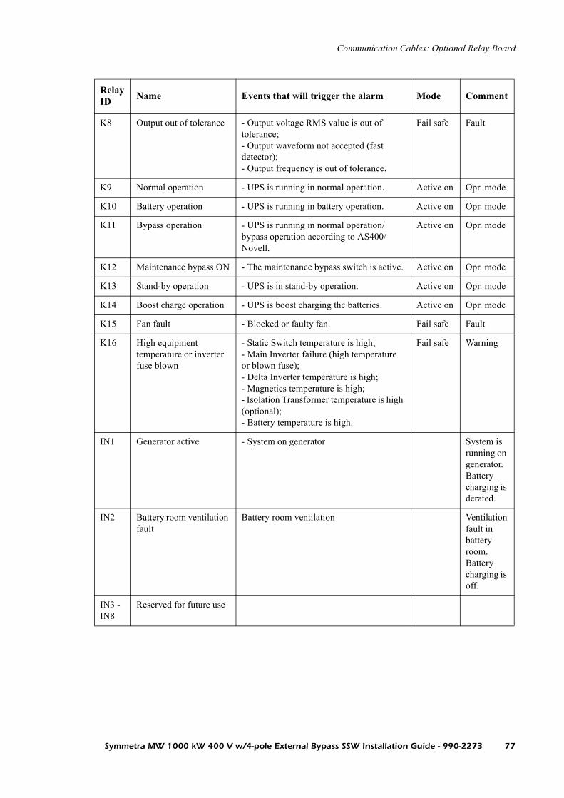
Communication Cables: Optional Relay Board
K8 Output out of tolerance - Output voltage RMS value is out of tolerance;- Output waveform not accepted (fast detector);- Output frequency is out of tolerance.
Fail safe Fault
K9 Normal operation - UPS is running in normal operation. Active on Opr. mode
K10 Battery operation - UPS is running in battery operation. Active on Opr. mode
K11 Bypass operation - UPS is running in normal operation/bypass operation according to AS400/Novell.
Active on Opr. mode
K12 Maintenance bypass ON - The maintenance bypass switch is active. Active on Opr. mode
K13 Stand-by operation - UPS is in stand-by operation. Active on Opr. mode
K14 Boost charge operation - UPS is boost charging the batteries. Active on Opr. mode
K15 Fan fault - Blocked or faulty fan. Fail safe Fault
K16 High equipment temperature or inverter fuse blown
- Static Switch temperature is high;- Main Inverter failure (high temperature or blown fuse);- Delta Inverter temperature is high;- Magnetics temperature is high;- Isolation Transformer temperature is high (optional);- Battery temperature is high.
Fail safe Warning
IN1 Generator active - System on generator System is running on generator.Battery charging is derated.
IN2 Battery room ventilation fault
Battery room ventilation Ventilation fault in battery room.Battery charging is off.
IN3 - IN8
Reserved for future use
Relay ID Name Events that will trigger the alarm Mode Comment
Symmetra MW 1000 kW 400 V w/4-pole External Bypass SSW Installation Guide - 990-2273 77


Specifications
Low-Impedance/High-Impedance Grounding
The Symmetra® MW is easily integrated into either a solid grounded Wye system, or a high-impedance grounded system.
In a solid grounded system, the neutral power source (utility, generator, or UPS) is solidly grounded. In the event of a down-stream ground fault, the fault current will have a path back to the source, and the over-current device feeding the faulted part of the installation will trip and isolate the fault.
In a high-impedance grounded system, the source is grounded with an impedance (grounding resistor). In the event of a down-stream fault, the fault current will be limited by the impedance of the grounding resistor. The value of a high-impedance system is its ability to maintain operation with a given system fault to ground, i.e. the over-current device will only trip at line-to-line faults or double ground faults. For a high-impedance system to provide enhanced power system reliability and availability, a ground-fault monitoring/alarm system is required.
Note
Grounding electrode conductor to be supplied by the customer.
For more information refer to “Appendix D - System and Protective Earthing” in Installation Guide.
Symmetra MW 1000 kW 400 V w/4-pole External Bypass SSW Installation Guide - 990-2273 79

Electrical Specifications
AC Input
Note
The installation is a typical installation including ancillary equipment, which is available from APC.
WARNING!Supply the UPS from a dedicated, 3 × 400/230 V, L1, L2, L3, N, PE source or a high-impedance grounded system.
CAUTION!Ensure clockwise phase rotation (L1, L2, L3) of input voltages.
CAUTION!AC and DC disconnect switches and over-current protection must be included in the installation.
Note
All wiring must comply with all applicable national and/or local electrical wiring rules.
Note
Max. prospective RMS short-circuit current on input terminals: 200 kAMax. prospective RMS short-circuit current on DC terminals: 50 kA
AC Input
Input rating 1000 kW/kVA
Power Factor 1
Input Voltage 380 V
Input Frequency 50 Hz
Nominal input current (note 1) 1573 A
Input Current Limitation (note 2) 1778 A
Input Voltage 400 V
Input Frequency 50 Hz
Nominal input current (note 1) 1494 A
Input Current Limitation (note 2) 1838 A
Input Voltage 415 V
80 Symmetra MW 1000 kW 400 V w/4-pole External Bypass SSW Installation Guide - 990-2273

Specifications: Electrical Specifications
DC Input
AC Output
Heat dissipation
Heat dissipation 30.92 kW / 105.5 kBTU/hr (note 6)
Input Frequency 50 Hz
Nominal input current (note 1) 1440 A
Input Current Limitation (note 2) 1809 A
AC Input
DC Input
Nominal Voltage (note 3) 2 x 384 V
INom Discharge (note 4) 1356 A
IMax Discharge (note 5) 1595 A
AC Output
Voltage 380 V
- Current Nom 1519 A
- Max (note 7) 1899 A
Voltage 400 V
- Current Nom 1443 A
- Max (note 7) 1804 A
Voltage 415 V
- Current Nom 1391 A
- Max (note 7) 1739 A
Symmetra MW 1000 kW 400 V w/4-pole External Bypass SSW Installation Guide - 990-2273 81

Specifications: Electrical Specifications
Notes
1. Nominal (Nom): Input current based on rated load, nominal input voltage and fully charged batteries.
2. Current limitation is maximum allowed via electronic current limiting and is based on full battery recharge + nominal load and -10% input voltage.
3. Nominal battery voltage assumed to be 2.0 volts/cell (lead technology).
4. Nominal Battery Discharge current based on rated load, and nominal Battery voltage.
5. Maximum Battery Discharge current based on rated load at end of Discharge.
6. Heat dissipation calculated at rated load capacity.
7. This current is at 125% of rated load and is electronically current-limited to a maximum of 10 minutes. This value is only provided so the engineer can ensure that the selected AC output circuit overcurrent device’s time-current characteristic will support this condition.
Torque specifications
CAUTION!The minimum DC voltage rating of the battery supply over-current protective device is 500 V.
Torque specifications
Bolt Size M8 13.5 Nm
Bolt Size M10 30 Nm
Bolt Size M12 50 Nm
Bolt Size M14 75 Nm
82 Symmetra MW 1000 kW 400 V w/4-pole External Bypass SSW Installation Guide - 990-2273

Required Breaker Settings
The Symmetra® MW is a fault-tolerant system capable of handling and surviving overloads and internal/external faults. The overload performances and fault clearings are possible when the specified minimum requirements for breaker settings are met. The settings are specified in the tables below, but some of them can also be found in the Electrical Specification section. The settings are all minimum settings and may not result in a drop-out.
The tables Input and upstream breakers and Output and downstream breakers give an overview of the affected breakers in different situations:
Input and upstream breakers - minimum settings
Output and downstream breakers - minimum settings
See separate guide on parallel operation for information on required breaker settings in parallel systems.
Q1, Q5, and any upstream breaker
Duration [S] Current [A] Total load [%] Event/Operation
< 0.005 18 kA -- Internal fault clearing
600 1838* 127 Overload on-line
1494 100 On-line
* Only applicable to Q1
∞
Q2, Q4, Q6, and any downstream breaker
Duration [S] Current [A] Total load [%] Event/Operation
< 0.005 18 kA -- Internal fault clearing. Will end as upstream.
60 2886* 200 Overload on-line
600 1804* 125 Overload on-line
1443 100 On-line
* Only applicable to Q2 and Q4
∞
Symmetra MW 1000 kW 400 V w/4-pole External Bypass SSW Installation Guide - 990-2273 83

Specifications: Required Breaker Settings
18 kA is the maximum peak let-through current (including safety factor) available during clearing of an internal fault in a 200 kW section or a Power Module. During or after a controlled fault clearing, no breakers are allowed to trip on the instantaneous trip setting below the specified value. The maximum peak let through current is applicable to utility with prospective short-circuit currents up to 200 kA.
The following diagram shows a dual mains system in which the upstream breakers are named Q. Correct settings of upstream breaker settings are mandatory. The system can also be configured as a single mains system.
Note
The instantaneous trip setting must not be derated even though the UPS system is derated in system output power. The system size has no influence on the instantaneous trip setting.
Note
For derated systems, the APC Application Team provides correct breaker settings and breaker frame sizes.
Note
For upstream breakers not mentioned in the table, the APC Application Team provides the correct settings for on-line, overload, and trip currents breaker settings.
Q1 Q2
Q3
Q6Q5
Q4
Q
Q
T1
T2
Dual Mains Installation
84 Symmetra MW 1000 kW 400 V w/4-pole External Bypass SSW Installation Guide - 990-2273

Operating, Storage and Transport
Operating conditions
Storage conditions
Transport conditions
The UPS is intended for installation in a temperature-controlled indoor area, free of conductive contaminants.
Amb. temperature range: 0 - 40oC
Relative humidity: <95%Non-condensing
Max. elevation for rated output:0-1000 m.
For operation at higher elevation derate as follows:At 1500m: 0.95At 2000m: 0.91At 2500m: 0.86At 3000m: 0.82
Free space required above the UPS system for ventilation: 500 mm.
ON OFF EMO
CAUTION!Do not unpack the UPS Sections before the time of installation.
Ambient storage temperature
0 to 40oC
Height conditions during transport
UPS is able to sustain air transport
Symmetra MW 1000 kW 400 V w/4-pole External Bypass SSW Installation Guide - 990-2273 85


Front Bottom Trims and Panels
Installation of Front Bottom Trims
Mount end plates as shown and attach using the (2) M6 screws for each end plate.
On the front of the UPS and External Bypass SSW, attach bottom trims using (8) M6 screws for the Inverter and External Bypass SSW Sections, and (4) M6 screws for the Control and Input/Output Sections.
Control SectionInverter Section Input/Output Section
Symmetra MW 1000 kW 400 V w/4-pole External Bypass SSW Installation Guide - 990-2273 87

Installation of Dead Front Panels and Finishing Panels
Dead front panel
To install a dead front panel (which holds the remaining 4 panels), position the 2 slots at the bottom of the dead front panel over the 2 guide taps at the bottom of the section. Then slant the dead front panel back to engage the locking device on the section.
Using a Torx screwdriver, fasten the (2) M6 screws at the top of the dead front panel. For torque values, refer to “Specifications” section.
Note
The front bottom trims should be installed prior to the installation of the dead front panel.
88 Symmetra MW 1000 kW 400 V w/4-pole External Bypass SSW Installation Guide - 990-2273

Front Bottom Trims and Panels: Installation of Dead Front Panels and Finishing Panels
Finishing panel
To install the top finishing panel, position the 2 guiding taps at the top of the panel over the slots of the dead front plate below.
Push firmly into place.
.
Finishing panel
Symmetra MW 1000 kW 400 V w/4-pole External Bypass SSW Installation Guide - 990-2273 89


IP21 Drip Cover (Option)
The IP 21 Drip Cover provides added protection against corrosive materials that might otherwise seep into the system. This solution physically covers all system sections with a shield and may also be applied to any optional equipment used in the configuration.CAUTION!Only qualified personnel may install the UPS.
Note
For top cable entry, punch holes in the IP21 Drip Cover for cables. After cables have been installed, seal holes for waterproofing.
Note
Always first install left end plate of the Drip Cover (applicable to both Configuration I and II).
Symmetra MW 1000 kW 400 V w/4-pole External Bypass SSW Installation Guide - 990-2273 91

Installation of IP21 Drip Cover
ON OFF EMO
~~
Normal
UPS SummaryNormal
300mm
36 x Re-fasten top plate screws.
Position 9 plates, starting with one end plate.
1 Right end plate.1 Left end plate.
Position 5 small and 2 large plates as shown
Replace 36 screws with IP 31stand-off pins (shipped with unit). Tighten stand-offs, using a 17-mm wrench.
Remove 36 screws from the top plate. Set aside for step 4.
Follow the same procedure for the External Bypass SSW
92 Symmetra MW 1000 kW 400 V w/4-pole External Bypass SSW Installation Guide - 990-2273

Warranty
Factory Warranty
APC warrants that the unit, when properly installed and commissioned by APC or APC authorized service personnel, shall be free from defects in materials and workmanship for a period of (1) year from the date of installation or maximum 18 months after manufacturing. In the event that the unit fails to meet the foregoing warranty, APC shall for a period of one (1) year repair or replace any defective parts, without charge for on-site labor and travel if trained & authorized APC personnel has conducted start-up of the unit.
An APC Start-Up Service must be performed/completed by APC or by service personnel authorized by APC. If not, the on-site factory warranty will be voided and replacement of defective parts only will be covered. APC shall have no liability and no obligation to repair the installed unit if non-authorized APC personnel performed the start-up and such start-up caused the unit to be defective.
APC shall not be liable under the warranty if its testing and examination disclose that the alleged defect in the product does not exist or was caused by purchaser’s or any third person’s misuse, negligence, improper installation or testing, unauthorized attempts to repair or modify, or any other cause beyond the range of the intended use, or by accident, fire, lightning or other hazard.
There are no warranties, expressed or implied, by operation of law or otherwise, of products sold, serviced or furnished under this agreement or in connection herewithin. APC disclaims all implied warranties of merchantability, satisfaction and fitness for a particular purpose. APC’s express warranties will not be enlarged, diminished, or affected by and no obligation or liability will arise out of, APC rendering of technical or other advice or service in connection with the products. The foregoing warranties and remedies are exclusive and in lieu of all other warranties and remedies. The warranties set forth above, constitute APC’s sole liability and purchaser’s exclusive remedy for any breach of such warranties. APC’s warranties apply only to purchaser and are not extended to any third parties.
In no event shall APC, its officers, directors, affiliates or employees be liable for any form of indirect, special, consequential or punitive damages, arising out of the use, service or installation, of the products, whether such damages arise in contract or tort, irrespective of fault, negligence or strict liability or whether APC has been advised in advance of the possibility of such damages.
Symmetra MW 1000 kW 400 V w/4-pole External Bypass SSW Installation Guide - 990-2273 93


Appendices
Appendix A
Accessory Kits for UPS System
Acessory Kit I.
Bottom Trims, front Units
Bottom Trims for Control and Input/Output Sections 2
M6, 12 mm torx cap screw for Bottom Trims 16
Bottom Trim for Inverter Section 1
M6 nylon lock washer 16
Bottom Trims, rear Units
Bottom Trim for Control and Input/Output Section 2
M6, 12 mm torx cap screw for Bottom Trims 16
Bottom Trim for Inverter Section 1
M6 nylon lock washer 16
Bottom Trims, left and right side Units
Bottom Trim, right 1
Bottom Trim, left 1
Symmetra MW 1000 kW 400 V w/4-pole External Bypass SSW Installation Guide - 990-2273 95

Appendices: Appendix A
Accessory Kit II.
Busbars to be used when Inverter Section is positioned to the right Units
Copper rails for Control and Input/Output Section 1
30 mm isolater 6
M8 x 20 mm bolt 6
M8 flat washer 6
M8 spring washer 6
Busbars for installation between sections Units
Copper rails Control - Inverter Section 1
Copper rails Control - Input/Output Section 1
M8 nut for for Copper rails 120
M8 x 35 mm bolt for Copper rails 24
M8 flat washer for Copper rails 144
M8 spring washer for Copper rails 144
Extension for Control Wire (applicable to Configuration II only) Units
Extensions for control wires Input/Output - Control Section (set of 2) 1
Mounting Plate for AMP Plug Units
Mounting plate for AMP plugs 1
M6, 12 mm combi screws with washers 2
Cable Ties Units
Cable ties, hinged 90
Cable ties, straight 60
Cable ties (flat ribbons) 30
Crane, Ramp and Level Shims Units
Crane 1
Lifting Profile (for attachment to Power Module) 1
M8 x 20 mm bolt for Lifting Profile 2
Crane Holder I 2
Crane Holder II 1
Ramp for Static Switch Module 1
Level Shims 50
96 Symmetra MW 1000 kW 400 V w/4-pole External Bypass SSW Installation Guide - 990-2273

Appendices: Appendix A
Front Assembly Brackets Units
Front Assembly Brackets 2
M6, 12 mm torx stud for brackets 40
Rear Assembly Brackets Units
Rear Assembly Brackets 4
M8 x 25 mm bolt for brackets 16
M8 flat washer for brackets 16
M8 spring washer for brackets 16
Angles Units
Angle for ID label 3
M4, 12 mm torx cap screw for angle 6
M4, 12 mm combi screw with washers 6
Communication Cables Units
P-bus cables 2
Symmetra MW 1000 kW 400 V w/4-pole External Bypass SSW Installation Guide - 990-2273 97

Appendix B
Accessory Kit for 2 MW 4-pole External Bypass Static Switch.
Units
Bottom Trim, right 1
Bottom Trim, left 1
Front Bottom Trim 2
Rear Bottom Trim 2
M6 x 12 mm screws, PN HD TX DIN7985 18
M6, Nylon Lock Washer 18
98 Symmetra MW 1000 kW 400 V w/4-pole External Bypass SSW Installation Guide - 990-2273

Appendix C
Removal of finishing panels and dead front panel
Pull lower part of top finishing panel free of the UPS section.
Lift top finishing panel and remove.
Dead front panel
Finishing panel
Symmetra MW 1000 kW 400 V w/4-pole External Bypass SSW Installation Guide - 990-2273 99
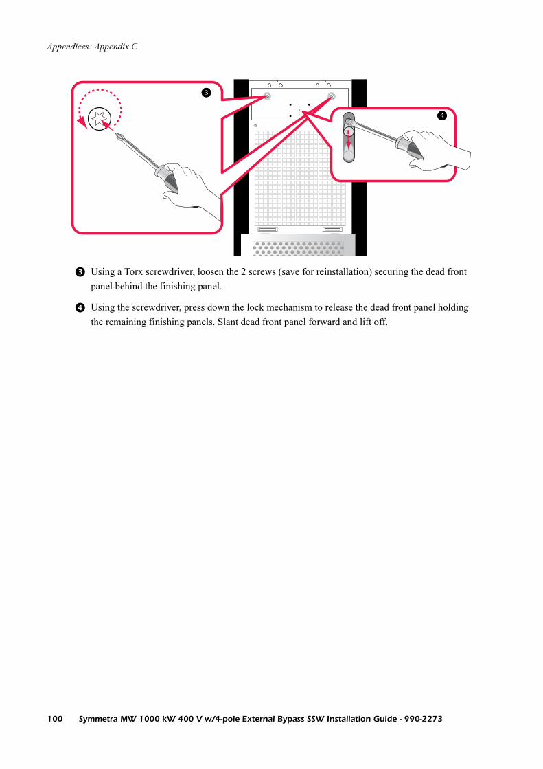
Appendices: Appendix C
Using a Torx screwdriver, loosen the 2 screws (save for reinstallation) securing the dead front panel behind the finishing panel.
Using the screwdriver, press down the lock mechanism to release the dead front panel holding the remaining finishing panels. Slant dead front panel forward and lift off.
100 Symmetra MW 1000 kW 400 V w/4-pole External Bypass SSW Installation Guide - 990-2273

Appendix D - System and Protective Earthing
The purpose of this appendix is to describe the system- and protective earthing principles of the Symmetra® MW.
CAUTION!All wiring to be in accordance with applicable national and/or local electrical wiring rules.
Symmetra MW 1000 kW 400 V w/4-pole External Bypass SSW Installation Guide - 990-2273 101

TN Systems
Characteristics
TN systems have one point connected directly to ground. All exposed conductive parts must be connected to that point by protective conductors.
Depending on the way the neutral and protective conductors are fed, there are three types of TN systems:
• TN-S system: a separate protective conductor is used in the system
• TN-C-S system: the neutral and protective conductors are combined to one single conductor in a part of the system
• TN-C system: the neutral and protective conductors are combined to one single conductor in the whole system
Reference to IEC 60364-4-41 413.1.3
All exposed conductive parts of the installation must be connected to the earthed point of the power system by protective conductors which must be earthed at or near to each relevant transformer or generator.
Exposed conductive parts that are accessible at the same time must be connected to the same earthing system, either individually, in groups or collectively.
Normally the earthed point of the power system is the neutral point. If a neutral point is not available or accessible, a phase conductor must be earthed. The phase conductor must not serve as a PEN conductor.
In fixed installations a single conductor may serve both as a protective conductor and a neutral conductor (PEN conductor).
Reference to IEC 60364-5-54 546.2.3
If from any point in the installation the neutral and protective functions are provided by separate conductors, it is inadmissible to connect these conductors to each other from that point. At the point of separation, separate terminals or bars must be provided for the protective and neutral conductors. The PEN conductor must be connected to the terminal or bar intended for the protective conductor.
If there are other effective earth connections, the protective conductors must be connected to such points when it is possible. It may be necessary to earth at additional points to ensure that the potentials of protective conductors remain as close as possible to that of earth in case of a fault.
102 Symmetra MW 1000 kW 400 V w/4-pole External Bypass SSW Installation Guide - 990-2273

Appendices: TN Systems
Additional requirements for generating sets (IEC 60364-5-55 551.4.2)
To be used when the generating set provides a switched alternative to the public supply.
Protection by automatic disconnection of supply must not rely on the connection to the earthed points of the public supply system when the generator is operating as a switched alternative to a TN system. A suitable earth electrode must be provided.
Protective devices in TN systems
The following protective devices are recognized in TN systems:
• Overcurrent protective devices
• Residual current protective devices (not to be used in TN-C systems)
When a residual current protective device is used in a TN-C-S system, a PEN conductor must not be used on the load side. The connection of the protective conductor to the PEN conductor must be made on the source side of the residual current protective device (see below illustration):
L1 L1L1 L1
L1 L1PEN N
SOURCE SOURCE
PE
Res
idu
al C
urr
ent
Sen
se
Symmetra MW 1000 kW 400 V w/4-pole External Bypass SSW Installation Guide - 990-2273 103

Appendices: TN Systems
The characteristics of protective devices and the circuit impedances shall be such that, if a fault of negligible impedance occurs anywhere in the installation between a phase conductor and a protective conductor or exposed conductive part, automatic disconnection of the supply will occur within 5 seconds (valid for distribution circuits), the following condition fulfilling this requirement:
In the condition:
If a fault occurs close to the UPS (before the power distribution) while the UPS system is in Battery Operation and Bypass is unavailable, the available power is unable to activate the protective device. In that situation the Inverter will shut down in five seconds (IEC 60364-4-41 413.1.3.5 norm). If a residual current protective device is used, this device will disconnect the supply.
The four diagrams show the Symmetra MW installed in four different TN systems:
• Earthing arrangements and protective conductors - Symmetra® MW in “TN-S installation”
• Earthing arrangements and protective conductors - Symmetra® MW in “TN-S installation” (Legal in DK - special cases)
• Earthing arrangements and protective conductors - Symmetra® MW in “TN-C-S installation”
• Earthing arrangements and protective conductors - Symmetra® MW in “TN-C installation”
is the impedance of the fault loop comprising the source, the live conductor up to the point of the fault, and the protective conductor between the point of the fault and the source
is the current causing the automatic operation of the disconnecting protective device within a conventional time not exceeding five seconds
is the nominal AC RMS voltage to earth
Zs Ia× U0≤
Zs
Ia
U0
104 Symmetra MW 1000 kW 400 V w/4-pole External Bypass SSW Installation Guide - 990-2273

TT Systems
Characteristics
TT systems have one point connected directly to ground and all exposed conductive parts of the installation must be connected to an earth electrode. This earth electrode is independent of the power system earthed point.
Reference to IEC 60364-4-41 413.1.4
All exposed conductive parts that are protected collectively by the same protective device must be connected to a common earth electrode together with the protective conductors. In installations where several protective devices are utilized in series, the requirement applies separately to all exposed conductive parts protected by each device.
The neutral point or, if a neutral point does not exist, a phase conductor of each generator station or transformer station must be earthed.
Protective devices in TT systems
The following protective devices are recognized in TT systems:
• Overcurrent protective devices
• Residual current protective devices
Overcurrent protective devices are only applicable for protection against indirect contact in TT systems where a low RA value exists (see specification below).
The condition must be fulfilled.
In the condition:
For discrimination purposes, S-type residual current protective devices may be used in series with general type residual current protective devices. To provide discrimination with S-type residual current protective devices, an operating time not exceeding 1 second is permitted in distribution circuits.
is the sum of resistance of the earth electrode and the protective conductor for the exposed conductive parts
is the current causing the automatic operation of the protective device. When the protective device is a residual current protective device, Ia is the rated residual operating current I n
RA Ia× 50V≤
RA
Ia
∆
Symmetra MW 1000 kW 400 V w/4-pole External Bypass SSW Installation Guide - 990-2273 105

Appendices: TT Systems
When the protective device is an overcurrent protective device, it must be either:
• a device with inverse time characteristics and Ia must be the current causing automatic operation within 5 seconds, or
• a device with an instantaneous tripping characteristic and Ia must be the minimum current causing instantaneous tripping
The following diagram shows a Symmetra® MW installed in a TT system:
• Earthing arrangements and protective conductors - Symmetra® MW in “TT installation”
106 Symmetra MW 1000 kW 400 V w/4-pole External Bypass SSW Installation Guide - 990-2273

IT Systems
Characteristics
In IT systems the installation is insulated from earth or connected to earth through a sufficiently high impedance. Exposed conductive parts are earthed individually, in groups, or collectively.
Reference to IEC 60364-4-41 413.1.5
In IT systems the installation must be insulated from earth or connected to earth through a sufficiently high impedance. This connection must be made either at the neutral point of the system or at an artificial neutral point. The latter may be connected directly to earth if the resulting zero-sequence impedance is sufficiently high. In installations where no neutral point exists, a phase conductor can be connected to earth through an impedance. In case of a single fault to an exposed conductive part or to earth, the fault current will be low and disconnection will not be imperative.
Exposed conductive parts must be earthed individually, in groups or collectively and the condition must be fulfilled.
In the condition:
In systems where an IT system is used for continuity of supply, an insulation monitoring device must be provided to indicate the occurrence of a first fault from a live part to the exposed conductive parts or to the earth. It is recommended to eliminate a first fault as soon as possible.
Depending on whether all exposed conductive parts are interconnected by a protective conductor (collectively earthed) or are earthed in groups or individually, after a first fault, the disconnection conditions of the supply for a second fault must be as follows:
a. In installations where the exposed conductive parts are earthed in groups or individually, the protection conditions for TT systems apply (see 413.1.4.1)
b. In installations where the exposed conductive parts interconnected by a protective conductor collectively earthed, the conditions for TN systems apply
In installations where the neutral is not distributed, the following conditions must be fulfilled:
is the resistance of the earth electrode for exposed conductive parts
is the fault current of the first fault of negligible impedance between a phase conductor and an exposed conductive part. The Id value takes the leakage currents and the total earthing impedance of the electrical installation into account
RA Id× 50V≤
RA
Id
Zs3 U0×2 Ia×
--------------------≡
Symmetra MW 1000 kW 400 V w/4-pole External Bypass SSW Installation Guide - 990-2273 107

Appendices: IT Systems
In installations where the neutral is distributed, the following conditions must be fulfilled:
In the condition:
Protective devices in IT systems
The following protective devices are recognized in IT systems:
• Insulation monitoring devices
• Overcurrent protective devices
• Residual current protective devices
The following diagram shows a Symmetra® MW installed in a IT system:
• Earthing arrangements and protective conductors - Symmetra® MW in “IT installation”
is the nominal AC RMS voltage between phase and neutral
is the impedance of the fault loop comprising the phase conductor and the protective conductor of the circuit
is the impedance of the fault loop comprising the neutral conductor and the protective conductor of the circuit
is the operating current of the protective device. The disconnecting time is 5 seconds (distribution circuits)
Z′sU0
2 Ia×-------------≤
U0
Zs
Z′s
Ia
108 Symmetra MW 1000 kW 400 V w/4-pole External Bypass SSW Installation Guide - 990-2273

Technical Support
Note the UPS serial number (located behind the cover of the display) before calling technical support.Local, country-specific centers: go to www.apc.com/support/contact.
Europe, Middle East and Africa 00800 0272 0479
Symmetra MW 1000 kW 400 V w/4-pole External Bypass SSW Installation Guide - 990-2273 109


Res
idua
l Cur
rent
Se
nse
Mains - input UPS - output
PE
N
PE
PE
PE
Bypass - input Bypass - output
L1
L3
L2
L1
L3
L2
N
L1
L3
L2
L1
L3
L2
Protective Earthing Conductor
Pro
tect
ive
Ear
thin
g C
ondu
cto
r
Main Protective Earthing Terminal
External SSW-Bypass
Symmetra MW
( PDU )Service Entrance
Maininverter
u
u uM
Main Protective Earthing Terminal
N
PE
PE
Q1
Q6
Q3
Q5
Earthing arrangements and protective conductors - Symmetra MW in TN-S installation
E
Suitable earth electrodewith reference to IEC 60364-5-55 § 551.4.2
With reference to:IEC 60364-4-41 § 413.1.3.1 - NOTE 1
Residual current protective devicecan be used.
Res
idua
l Cur
rent
Se
nse
Residual current protective device can not beused at this point.Owing to parallel return path for the fault current
With reference to:IEC 60364-4-41 § 413.1.3.1
Minimum cross-sectional areas:IEC 364-5-54 § 543.1.1
+ - + -
Bat
tery
1
Bat
tery
2
Q7 Q8
Battery 1 Battery 2
PE
PE
Batteryrack
Batterybreakerbox
Q4
DeltaInverteri
i
i
Com
mon
-mod
e fil
ter
Switchgear
See: IEC 60364-4-41 § 413.1.3

Res
idua
l Cur
rent
Se
nse
Mains - input UPS - output
PE
N
PE
PE
PE
Bypass - input Bypass - output
L1
L3
L2
L1
L3
L2
N
L1
L3
L2
L1
L3
L2
Protective Earthing Conductor
Pro
tect
ive
Ear
thin
g C
ondu
cto
r
Main Protective Earthing Terminal
External SSW-Bypass
Symmetra MW
( PDU )Service Entrance
Maininverter
u
u uM
Main Protective Earthing Terminal
N
PE
PE
Q1
Q6
Q3
Q5
Earthing arrangements and protective conductors - Symmetra MW in "TN-S installation"( Legal in DK - special cases )
E
With reference to:IEC 60364-4-41 § 413.1.3.1 - NOTE 1
Residual current protectivedevice can be used.
Res
idua
l Cur
rent
Se
nse
Residual current protective device can not beused at this point.Owing to parallel return path for the fault current
With reference to:IEC 60364-4-41 § 413.1.3.1
Minimum cross-sectional areas:IEC 364-5-54 § 543.1.1
+ - + -B
atte
ry 1
Bat
tery
2
Q7 Q8
Battery 1 Battery 2
PE
PE
Batteryrack
Batterybreakerbox
Q4
DeltaInverteri
i
i
Com
mon
-mod
e fil
ter
Switchgear
Legal in DK ( Special cases )
With reference to:Stærkstrømsbekendtgørelsen § 55 1.6.3 Note( § 551.6.3 is missing in IEC 60364-5-55 )
See: IEC 60364-4-41 § 413.1.4 and "Stærkstrømsbekendtgørelsen" § 551.6.3, Note

Res
idua
l Cur
rent
Se
nse
Mains - input UPS - output
PE
N
PE
PE
PE
Bypass - input Bypass - output
L1
L3
L2
L1
L3
L2
N
L1
L3
L2
L1
L3
L2
PE
Pro
tect
ive
Ear
thin
g C
ondu
cto
r
Main Protective Earthing Terminal
External SSW-Bypass
Symmetra MW
( PDU )Service Entrance
Maininverter
u
u uM
Main Protective Earthing Terminal
PEN
PE
Q1
Q6
Q3
Q5
Earthing arrangements and protective conductors - Symmetra MW in "TN-C-S installation"
E
Suitable earth electrodewith reference to IEC 60364-5-55 § 551.4.2
With reference to:IEC 60364-4-41 § 413.1.3.1 - NOTE 1
Residual current protectivedevice can be used.
Res
idua
l Cur
rent
Se
nse
Residual current protectivedevice can not be used.
With reference to:IEC 60364-4-41 § 413.1.3.1
+ - + -
Bat
tery
1
Bat
tery
2
Q7 Q8
Battery 1 Battery 2
PE
PE
Batteryrack
Batterybreakerbox
Q4
DeltaInverteri
i
i
Com
mon
-mod
e fil
ter
Switchgear
PEN
See: IEC 60364-4-41 § 413.1.3

Mains - input UPS - output
PE
N
PE
PE
PE
Bypass - input Bypass - output
L1
L3
L2
L1
L3
L2
N
L1
L3
L2
L1
L3
L2
Main Protective Earthing Terminal
External SSW-Bypass
Symmetra MW
( PDU )Service Entrance
Maininverter
u
u uM
Main Protective Earthing Terminal
PEN
PE
Q1
Q6
Q3
Q5
Earthing arrangements and protective conductors - Symmetra MW in TN-C installation
E
Suitable earth electrodewith reference to IEC 60364-5-55 § 551.4.2
With reference to:IEC 60364-4-41 § 413.1.3.1
+ - + -
Bat
tery
1
Bat
tery
2
Q7 Q8
Battery 1 Battery 2
PE
PE
Batteryrack
Batterybreakerbox
Q4
DeltaInverteri
i
i
Com
mon
-mod
e fil
ter
Switchgear
N
PEN
PEN PEN
PEN
The "Common-Mode Filter" has no effect in thissystem configuration.
This system configuration is not recommended
See: IEC 60364-4-41 § 413.1.3

Res
idua
l Cur
rent
Se
nse
Mains - input UPS - output
PE
N
PE
PE
PE
Bypass - input Bypass - output
L1
L3
L2
L1
L3
L2
N
L1
L3
L2
L1
L3
L2
PE
Pro
tect
ive
Ear
thin
g C
ondu
cto
r
Main Protective Earthing Terminal
External SSW-Bypass
Symmetra MW
( PDU )Service Entrance
Maininverter
u
u uM
Main Protective Earthing Terminal
N
PE
Q1
Q6
Q3
Q5
Earthing arrangements and protective conductors - Symmetra MW in TT installation
E
Suitable earth electrode: RA x Ia < 50V
With reference to IEC 60364-4-41 § 413.1.4.2
Residual current protective devicecan be used.
Res
idua
l Cur
rent
Se
nse
+ - + -B
atte
ry 1
Bat
tery
2
Q7 Q8
Battery 1 Battery 2
PE
PE
Batteryrack
Batterybreakerbox
Q4
DeltaInverteri
i
i
Com
mon
-mod
e fil
ter
Switchgear
See: IEC 60364-4-41 § 413.1.4
With reference to IEC 60364-4-41 § 413.1.4.1
Residual current protective device can not beused at this point.Owing to parallel return path for the fault current

Res
idua
l Cur
rent
Se
nse
Mains - input UPS - output
PE
N
PE
PE
PE
Bypass - input Bypass - output
L1
L3
L2
L1
L3
L2
N
L1
L3
L2
L1
L3
L2
( Alternative to earth electrode )
Ear
thin
g C
ondu
cto
r
Main Protective Earthing Terminal
External SSW-Bypass
Symmetra MW
( PDU )Service Entrance
Maininverter
u
u uM
Main Protective Earthing Terminal
N
PE
Q1
Q6
Q3
Q5
Earthing arrangements and protective conductors - Symmetra MW in "IT - installation"
E
Residual current protective devicecan be used.
+ - + -
Bat
tery
1
Bat
tery
2
Q7 Q8
Battery 1 Battery 2
PE
PE
Batteryrack
Batterybreakerbox
Q4
DeltaInverteri
i
i
Com
mon
-mod
e fil
ter
Switchgear
See: IEC 60364-4-41 § 413.1.5
Protective Earthing Conductor
InsulationMonitoringDevice
Requirement !!IEC 60664-4-41 § 413.1.5.4
Suitable earth electrode: RA x Id < 50VWith reference to IEC 60364-4-41 § 413.1.5.3Alternative:The exposed-conductive-parts can be earthed individually or in groups.But special demands are required. See IEC 60364-4-41 § 413.1.5.5 a)
Z
ZGroundingimpedance
Groundingimpedance