Embed Size (px)
Citation preview

USOO568591 1A
United States Patent [19] Raterman et al.
Patent Number:
Date of Patent:
[11]
[45]
5,685,911 *Nov. 11, 1997
[54] APPARATUS FOR INTERMITTENTLY APPLYING DISCRETE ADHESIVE COATINGS
[75] Inventors: John Raterman, Lawrenceville, Ga.; Jurgen Benecke, Brandenburger, Germany; Arthur Cieplik, Luneburg, Germany; Thomas Burmester, Bleckede, Germany; Michael L. Gill, Westlake, Ohio
[73] Assignee: Nordson Corporation, Westlake, Ohio
[*] Notice: The term of this patent shall not extend beyond the expiration date of Pat. No. 5,421,921.
[21] Appl. No.: 379,182 [22] Filed: Jan. 27, 1995
Related US. Application Data
[62] Division of Ser. No. 911,674, Jul. 8, 1992, Pat No. 5,418, 009.
[51] Int. Cl.6 .................................................... .. B05C 11/00
[52] US. Cl. .......... .. . 118/669; 118/324
[58] Field of Search .. .......... .. 118/410, 411,
118/324, DIG. 4, DIG. 2, 677, 669, 300, 308; 239/568, 597, 300, 297
[56] References Cited
U.S. PATENT DOCUMENTS
Re. 33,481 12/1990 Ziecker et al. . 1,747,581 2/1930 Frazier . 2,640,208 6/1953 De Florez et a]. . 3,595,204 7/1971 McIntyre . 3,672,570 6/1972 Scarbrough et al. . 3,750,955 8/1973 Nakai et a1. . 3,806,289 4/1974 Schwarz . 3,825,379 7/1974 Lohkamp et a]. . 3,870,233 3/1975 Wilhelm et a1. . 3,888,722 6/1975 Blair et a1. . 3,956,057 5/1976 Jung . 3,972,759 8/1976 Buntin . 4,047,861 9/1977 Balaz .
115
CON ROL A R
SIPFLY
M 7 VALVES
AIR HEITER “W7 van:
4,059,714 11/1977 Scholl et al. . 4,128,667 1211978 Timson. 4,133,970 1/1979 Lusk .
4,156,398 5/1979 McDaniel.
(List continued on next page.)
FOREIGN PATENT DOCUMENTS
1125960 6/ 1982 Canada . 0161936 11/1995 European Fat. 011. . 2824403 1211979 Germany .
891100463 8/1989 Germany . 0329813 3/1990 Germany . 0359943 3/1990 Germany .
54-170759 7/1981 Japan . WO9114510 10/1991 W'IPO .
OTHER PUBLICATIONS
931104186 dated Sep. 1993 European Search Report. The Waistband Phenomenon by Frederic McIntyre (N0 publication date available).
Primary Examiner—Brenda A. Lamb Attorney Agent, or Firm—Wood, Herron & Evans, L.L.P.
[57] ABSTRACT
Apparatus for producing intermittent, discrete patterns of coating material, such as hot melt adhesive, onto discrete substrates or substrate areas, such as book spines, sift-proof carton ?aps and pinch-bottom bags. The adhesive patterns have sharp, square leading and trailing edges, as well as side edges. A slot nozzle die has elongated air slots along the slot extrusion opening. In the operation of the apparatus, the air ?ow is initiated from both air slots prior to the initiation of the hot melt ?ow. Also, the air ?ow is continued beyond that point in time, when the hot melt ?ow ceases. The delays between the operations of the air ?ow and the hot melt ?ow are on the order of micro seconds. Coating weights down to 1 gram per square meter at about 350 meters per minute substrate speed are provided. Alternatively, the lead and lag air start and stop times on each side of the ?lm of coating material are di?’erent to control the exact disposition of the square cut-on and square cut-o?’ coating edge on the sub strate. Methods are disclosed.
37 Claims, 6 Drawing Sheets
CONTROLLER

5,685,911 Page 2
4,247,581 4,289,330 4,294,411 4,371,195 4,408,562 4,476,165 4,496,617 4,512,945 4,553,701 4,627,465 4,657,047 4,687,137 4,714,647 4,720,252 4,735,169 4,746,545 4,750,956 4,753,819 4,774,109 4,778,631 4,815,660
US. PATENT DOCUMENTS
l/1981 9/1981
10/1981 2/1983 10/1983 10/1984 1/1985 4/1985 11/1985 12/1986 4/1987 8/1987 12/1987 l/l988 4/1988 5/1988 6/1988 6/1988 9/1988
10/1988 3/1989
Cobbs, Jr. et a1. . Wiermanski .
Hasting et a1. . Wang et a1. .
DeCamp et a1. . McIntyre .
Parker .
V1gano ,
Rehman et a1. .
Kolibas et a1. .
Kolibas .
Boger et al. . Shipp, Jr. et a]. , Appel et a1. .
Cawston .
McIntyre .
Malachowski .
Shimada .
Hadzimihalis et a1. .
Cobbs, Jr. et a1. . Boger .
4,818,464 4,830,055 4,836,440 4,850,514 4,874,451 4,880,663 4,891,249 4,900,390 4,900,593 4,906,492 4,957,783 4,983,109 4,983,424 4,984,949 5,000,112 5,012,980 5,016,812 5,145,689 5,209,410 5,236,641 5,269,670
4/1989 5/1939 6/1989 7/1989 10/1989 11/1989 1/1990 2/1990 2/1990 3/1990 9/1990 l/1991 1/1991 1/1991 3/1991 5/1991 5/1991 9/1992 5/1993 8/1993
12/1993
Lau .
Kolibas .
French .
Scholl et a1. .
Boger et a1. .
Shimada .
McIntyre .
Colton et a1. .
Krippl .
Groshens .
Gabryszewski .
Miller et a1. .
Saidman et a], .
Reckziegel .
Rothen et a1. .
“may et a1. .
Pedigrew .
Allen et a1. .
Mchmann et a1, .
Allen et a1. .
Allen et a1. .

US. Patent Nov. 11, 1997 Sheet 1 of 6 5,685,911
75 2
M5 'CONTROLLER
CONTROL AIR
SUPPLY
, SOLENOID CONTROLLED
M62 VALVES , £06 PRESSURIZED ‘ PRESSURIZED AIR SOURCE ‘ AIR SOURCE
AIR HEATER
AIR ‘
HEATER 51/07
‘1/147
VALVE ..=P1 171?)‘ 1,:// 5? 338 K j") I
‘ \ y / / Q / \\ \\\\, wsvw/ // \ \4/\ \ :2/ 4a / \AA, \ \Vf ‘ /
W 1 \ / 1, s //M M m? 37 734 M
70 M0 ‘ as
/ f 39 if, 7/ / ‘ ///
34 64,1 élc" 4)” 6/ 53 33

US. Patent Nov. 11, 1997 Sheet 2 of 6 5,685,911

U.S. Patent Nov. 11, 1997 Sheet 3 of 6 5,685,911
CONTROLLER
75 SOLENOID
CON TROLLED VALVES
I05
L 0 R T N O C
V: an. IP AU 8
PRESSURIZED MELTING
AIR SOURCE
8 PUMPING AIR HEATER
3.3
3” FIG.3

US. Patent Nov. 11, 1997 Sheet 4 0f 6 5,685,911
SHADE/D45” SHOWS VEN OPERATING
RANGE
14 - q q q - _ 6 5 4. 3 2 .‘
83.2w zmai 635} 360 260 400
FIG.6 LINE SPEED (METERS PER MINUTE)

US. Patent Nov. 11, 1997 Sheet 5 of 6 ‘ 5,685,911
37x. 30/ Y i
w
w w FIG. 7 %
37 30/ ?g é’ Q2
W

US. Patent Nov. 11, 1997 Sheet 6 of 6 5,685,911
|
5,685,911 1
APPARATUS FOR INTERMITTENTLY APPLYING DISCRETE ADHESIVE
COATINGS
This application is a divisional of application Ser. No. 07/911,674, ?led Jul. 8, 1992, now US. Pat. No. 5,418,009.
This case is generally related to the following United States Patent Applications ?led on Jul. 8, 1992:
Title Inventors
Apparatus & Methods for I. Benecke; A. Cieplik; Applying Discrete Coating T. Burmester Serial No. 07/910,781, now abandoned
Segmented Slot Die for M. Gill; 1'. Benecke; Air Spray of Fibers A. Cieplik; T. Burmester Serial No. 07/910,784 now US. Pat. No. 5,421,921 Apparatus & Methods for Applying Discrete Foam Coatings Serial No. 07/910,768, now abandoned Apparatus & Methods for Applying Conformal Coatings to Electronic Circuit Boards Serial No. 07/910,686, now U.S.Pat. No. 5,354,373 Methods 8; Apparatus for Applying coatings to
I. Raterman; I. Benecke; A. Cieplik; T. Burmester; M. Gill
B. Roger, I. Benecke; A. Cicplik; T. Burmester; M. Gill
L. Hauser; J. Benecke; A. Cieplik; T. Burmester;
Bottles M. Gill; K. Washington; Serial No. 07/910,782 R. Evans now abandoned
Such applications are all commonly assigned and are expressly incorporated herein by reference.
This invention relates to the application of coatings to substrates and more particularly to the application to sub strates of discrete, uniform coatings having sharp and square cut-on and cut-0E edges.
Many industrial applications require the use of discrete, well de?ned and uniform adhesive coatings applied to predetermined areas. Such coatings are very useful in varied lamination processes, such as in book binding, sift-proof carton sealing and pinch-bottom bags, for example, and in other coating operations. ‘
In the production of discrete coatings and adhesives for lamination of discrete substrate areas, for example, it is desirable to obtain broad, uniformly thick coatings in a non-contact application process with sharp and square cut on and cut-01f edges with no stringing of material. None of the processes currently known are entirely suitable for this application.
Many various devices have been used to apply adhesives for lamination, including contact coaters, spray coaters, and, more recently, ?ne line or spiral pattern application devices. Contact coaters present the inherent disadvantage of wear and substrate index and tension tolerances. The spray, ?ne line and spiral pattern applicators do not generally produce highly de?ned square edge cut-on and cut-01f coating edges in a uniform broad coating, as are desired in a number of applications.
While not related to lamination applications generally, another technique used for producing ?brous non-woven webs is known as a melt-blowing process. One such example of the melt-blowing process is described in US. Pat. No. 4,720,252. In that device, hot melt thermoplastic material is extruded from a continuous slot opening and air is blown onto the extruding material from both sides of the slot opening to produce the desired webs. Such processes are
10
15
20
25
30
35
40
45
55
65
2 used for web production, and do not generally concern themselves with intermittent operation to produce discrete coatings, nor with extruding adhesives for lamination appli cations.
As noted above, there are numerous adhesive and sealing applications and processes which can bene?t from the use of square, sharp, cut-on and cut-off patterns.
For example, in book binding, adhesives are used to adhere a cover to a book spine. But that spine can be curved, ' and its curved discrete shape is not conducive to existing spray or slot technologies. Multi-ori?ce nozzles present clogging and maintenance issues. In sift-proof cartoning, it is necessary to apply an integral adhesive pattern of uniform thiclmess, without breaks, to ensure there is no channel for the escape of ?ne granules or particulates packaged. In pinch-bottom bags, it is desirable to apply uniform patterns consistently on an intermittent production basis to cover particular predetermined discrete areas.
In all of these applications, it is desirable to obtain the necessary coatings Without an applicator contact operation to reduce wear, yet while eliminating stringing of adhesive.
Accordingly, it has been one objective of this invention to produce broad, uniform, hot melt adhesive coatings with sharp side edges and sharp, square leading and trailing edges on intermittently presented discrete substrate areas for seal rng.
Another objective of this invention has been to provide methods and apparatus for intermittent non-contact applica tion of thermoplastic adhesive coating material, having sharp, square, side, leading and trailing edges, to discrete, predetermined areas.
To these ends, a preferred embodiment of the invention includes application of discrete adhesive patterns on prede termined substrate areas by means of a slot die means including a slot nozzle, elongated air channels on each side of the slot nozzle for impinging a ?ow of air on each side of an expanse of adhesive coating material extruding from the slot nozzle, and means for controlling the supply of material to the slot nozzle and the supply of air to the air channels so that each can be initiated and stopped at predetermined intervals to produce sharp, square leading and trailing edges in the deposited coatings.
In one mode, the air start-up on both sides precedes extrusion start-up and continues until after the extrusion is stopped. In another mode, the air on one side of the nozzle is started before extrusion is started and terminates before extrusion is stopped while air on another side of the nozzle starts at or after extrusion start-up and continues until after extrusion stops.
Continuation of air ?ow after exn'usion stoppage can draw coating material remaining at or in the nozzle into the air stream and onto a substrate, causing stringing. Accordingly, the delay of air stoppage after extrusion stop page is predetermined to produce good sharp, square coating pattern cut-off, but not so long as to draw remaining glue at the nozzle therefrom so as to cause stringing. The air start-up and stop delays are preferably on the order of micro seconds.
The invention produces uniform, wide or broad coatings having sharp side edges and sharp, square, leading and trailing edges coordinated with a predetermined underlying substrate area and applied in a non-contacting application process.
When used in book binding, the adhesive coatings herein do not string down the book sides. When used in sift-proof cartoning, uniform adhesive patterns with sharp cut-on and cut-o? leave no channels or openings for sift-through of

5,685,911 3
granular or particulate product. And when used with pinch bottom bags, the uniform discrete coatings described herein produce sealing in the precisely de?ned substrate areas with no wear of contacting adhesive applicator parts.
These and other objectives and advantages will become readily apparent from the following detailed description of a preferred embodiment of the invention and from the drawings in which:
BRIEF DESCRIPTION OF THE DRAWINGS
FIG. 1 is a diagrammatic side view in partial cross-section illustrating the invention;
FIG. 2 is an elevational side view in partial cross section of a slot nozzle coater according to the invention;
FIG. 3 is an elevational front view in partial cross-section of the apparatus of FIG. 2, illustrating diagrammatically control and flow features of the invention;
FIG. 4 is an exploded view of the slot nozzle die of FIG. 2;
FIG. 5 is a front view of the slotted or segmented shim used in the slot nozzle die of the invention;
FIG. 5A is a partial view of an alternative shim; FIG. 6 is a graph illustrating coating weight applied vs.
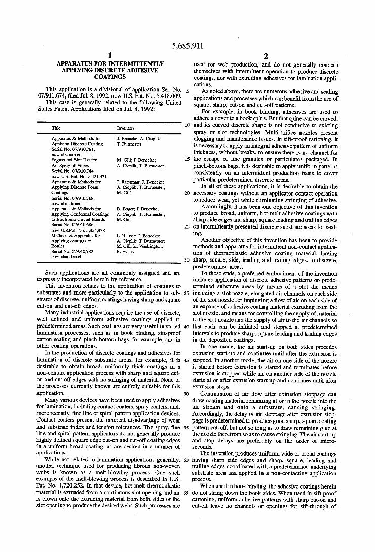
substrate line speed for a coater according to the invention; FIG. 7 is a diagrammatic view illustrating use of one
embodiment of the invention in a book binding application; FIG. 8 is a diagrammatic view illustrating use of one
embodiment of the invention in a sift-proof cartoning appli cation; and
FIG. 9 is a diagrammatic view illustrating use of one embodiment of the invention in a pinch-bottom bag appli cation.
DETAILED DESCRIPTION OF THE PREFERRED AND ALTERNATE
EMBODIMENTS
Turning now to the drawings, there will now be described the apparatus for generating discrete, uniform coatings hav ing sharp and square cut-on and cut-off edges. FIG. 1 illustrates various features of a die means 30 and air and hot melt adhesive controls according to the invention. The die means 30 comprises two die halves 31, 32, and two air blocks 33, 34. Each die block 31, 32 includes a downwardly depending projection 35, 36. The die halves 31, 32 de?ne between them an extrusion slot 37. Slot 37 is de?ned by the face 38 of the die half 31 and the face 39 of the die half 32. Face 38 is juxtaposed with respect to the face 39, as shown. The extrusion slot 37 terminates at an elongated slot nozzle or extrusion outlet 40.
As noted in the Figures, the air blocks extend below the outlet 40 to provide a degree of protection from mechanical damage.
Die half 32 includes a hot melt passageway 41 for receiving hot melt adhesive and conducting the hot melt adhesive to a “coat hanger” portion 42 of the die half 32, details of which are perhaps better seen in FIG. 4. A slotted or segmented shim 45, as best seen in FIG. 6, and a portion of which is seen in FIG. 1, is located between the juxtaposed surfaces 38 and 39 of the die halves 31 and 32. The shim 45 has a plurality of elongated projections 46, de?ning between them a plurality of elongated channels or slots 47.
Each of the projections has a downstream tapered end portion 48, having a pointed tip 49 which is ?ush with the lower edge 50 of the shim, and ?ush with the elongated slot
5
10
15
20
35
55
65
4 nozzle extrusion outlet 40 (FIG. 1). In FIG. 1, only the top portion 51 of the shim 45 is shown, for the purpose of clarity. Alternatively, an open shim with no projections 46 can be used. Also, another alternative shim is 45a, illustrated in FIG. 5A. Pointed tips 52 extend beyond slot outlet 40, preferably about two or three thousandths of an inch.
Returning now to FIG. 1, each of the upper die halves 31, 32 is provided with an air passageway 55, 56, extending from an upper surface of the die to a lower respective surface 57, 58. Each die half 31, 32 also includes an inclined surface 59, 60, depending from the surfaces 57 and 58, respectively. The inclined surfaces 59 and 60 de?ne one part of an air passage, or air slot 61 and 62, as will be described.
Turning now to the air blocks 33 and 34, it will be appreciated that each of them include an inclined surface 63 and 64, respectively. which de?ne the other side of the air slots 61 and 62 with the juxtaposed respective surfaces 59, 60, all as shown in FIG. 1. Each of the air blocks 33 and 34 include an upper surface 65, 66 juxtaposed to the respective lower surfaces 57 and 58 of the die halves 31, 32. An elongated air plenum 67, 68 is formed in each of the
air blocks 33, 34. The plenums 67, 68 are also seen in FIG. 4. Respective air passages 69 and 70 are formed in the respective air blocks 33 and 34 and extend from the respec tive surfaces 65 and 66 to a lower portion 71, 72 of the respective plenums 67, 68. Each of the plenums 67, 68 are primarily de?ned in the air blocks 33 and 34. However, when the die means 30 are assembled, the top area of each of the respective plenums 67, 68 are de?ned respectively by the lower surfaces 57 and 58 of the die halves 31, 32. These surfaces 57, 58 also form an upper portion of air passage 73 and 74, each of which respectively lead from their associated plenums 67 and 68 to the air slots 61 and 62. Accordingly, looking at the right hand side of FIG. 1, it will be appreciated that air can pass through the passageway 55 to the passage way 69 in air block 33, and from there to the plenum 67. “O”-rings, not shown, can be used at the interfaces of the respective die half and air block to seal passages 55, 56 with passages 69, 70, respectively. Pressurized air in the plenum 67 moves through the passageway 73 into the air slot 61.
In a like manner, air can be introduced to passageway 56 in the die half 32 and from there it can move into the air passageway 70 and into the lower portion of the plenum 68. From the plenum 68, pressurized air is directed through the air passage 74 into the air slot 62 of the air block 34.
Referring now brie?y to the upper portion of FIG. 1, it will be appreciated that a controller 75 is operationally connected to valves V-1 and V-2, as shown, for controlling the introduction of heated, pressurized air to the passages 55 and 56, respectively, in order to pressurize those passages and the downstream air passages as previously described, with air. At the same time, the controller 75 is operationally interconnected to a hot melt control valve 76 for controlling the supply of coating material, such as hot melt adhesive, to the hot melt adhesive passage 41 and to the internal coat hanger area 42 of the die means 30. While any suitable form of controller 75 can be used, as is well known, one particular controller comprises a PC-10 pattern controller, manufac tured by Nordson Corporation of Westlake, Ohio. The P010 pattern control 75 is operational to initiate and to stop the generation of air into passages 55 and 56, either simulta neously or independently. and also to initiate and to stop the hot melt ?owing through valve 76 so as to intermittently provide coating material to the passageway 41 indepen dently and at pre-selected times with respect to the provision of pressurized heated air to the passages 55 and 56, all in a manner as will be described.

5,685,911 5
The air slots 61 and 62 are oriented on an angle with respect to the elongation of the extrusion slot 37. Accordingly, when coating material is extruded through the slot 37 and outwardly of the extrusion outlet 40, air moving through the air slots 61 and 62 is impinged on the material before that material engages or is deposited on an underlying substrate which is presented for coating.
Turning now to FIGS. 2 and 3, there is shown more of the overall extrusion apparatus according to the invention. As shown in FIG. 2, the die means 30 is interconnected with air valves V-1, V-2 and hot melt valve 76, each of which is interconnected with an extrusion body 80 which operation ally interconnects the air and hot melt valves with the die means 30.
For clarity, a portion of the air valve V-2 is shown in partial cross section in FIG. 2. Since the valves V-l and V-2 are identical, only valve V-2 will be described Such air valves are manufactured and distributed by Nordson Cor poration through Nordson Engineering of Luneburg, Germany, under part no. 265701. Any other suitable air valve can be used.
Valve V-2 comprises a valve body 82 de?ning a valve chamber 83 and a control chamber 84, the two chambers being separated by the diaphragm 85. An extension 86 having a bore 87 extending therethrough depends from the valve body 82 and extends into the bore 88 of extrusion body 80 to form an annular chamber 89 therewith. Chamber 89 is interconnected with an annular passageway 90 in the valve body 82, which interconnects with the chamber 83. An annular chamber 91 is also de?ned in the valve body 82 and interconnects with the chamber 83. When control air is directed into chamber 84, the diaphragm 85 is pushed downwardly to seal off the annular passage 90 from the annular passage 91. On the other hand, when pressure is decreased in the control chamber 84, the diaphragm moves upwardly to the position shown in FIG. 3. Air in the inlet annular chamber 89, which is heated and under pressure, communicates through the annular passages 90 through the chamber 83 and the annular passage 91, into the outlet bore 87. Outlet bore 87 is connected through a passageway 92 to the air passage 56 in the upper die half 32, as shown in detail in FIG. 1, where the air from there can move to the plenum 68 and into the air slot 62.
In like manner. the air valve V-l is operable to selectively supply air to the air passage 93 in the extrusion body 80 and from there to the air passage 55 in the upper die half 31. Air moves through that passageway 55 into the plenum 67 and from there to the air slot 61. The hot melt valve 76 can be any suitable hot melt valve
which can be selectively controlled to initiate and to cut o?’ the ?ow of coating material, such as hot melt adhesive, to the die means 30. One such suitable valve is balanced valve model no. EP51 produced by Nordson Corporation of Westlake, Ohio. Such valve minimizes signi?cant change in pres sures when the valve is switched between its opened and closed positions. The valve 76 has a stem 96 seated over a port 97. When control air is supplied to an inlet 98, the stem 96 is lifted to permit hot melt adhesive in a chamber 99 to ?ow through the port 97 and into the hot melt passageway 41 of the upper die half 32. Hot melt adhesive is introduced into the chamber 99 through hot melt inlet 100. A hot melt outlet 101 is also interconnected with the chamber 99 to receive pressurized hot melt adhesive when the stem 96 is seated on port 97.
Any suitable apparatus can be utilized for melting and pumping hot melt adhesive to the valve 76. Such apparatus
10
15
20
25
35
45
50
55
65
6 is shown diagrammatically at 102. While any suitable appa ratus could be utilized, one particular form of apparatus which is suitable is the model HM640 applicator, manufac tured by Nordson Corporation of Westlake, Ohio.
FIG. 3 illustrates diagrarmnatically the various control inputs to the valves 76 and V-1. As shown in FIG. 3, the controller 75 is interconnected to a control air supply 105 for supplying control air to the valves V-l and V-2. A pressur ized air source 106 is interconnected to an air heater 107 which supplies process air to the valves V-1 and V-2 for transmission to the respective air slots 61, 62, as described above. When the respective valves V-l and V-2 are opened, controller 75 is also interconnected to the control air supply for supplying control air through closed and opened solenoid control valves (shown in FIG. 3) to open and close the hot melt valve 76.
Referring now more particularly to FIG. 1 and the details of the die means 30 as shown in FIG. 4, it will be appreciated that the plenums 67 and 68 in the air blocks 33, 34 communicate with the lower surfaces 73A and 74A, respectively, of the air passages 73 and 74 as previously described, and air emanating from the upper portion of the plenums 67 and 68 moves through the passageways 73 and 74 and then downwardly through the respective air slots 61, 62.
Turning now to the so-called “coat hanger” portion 42 of the upper die half 32, and with reference to FIG. 4, it will be appreciated that “coat hanger” dies are known in general. For example, one coat hanger-type die for handling hot melt adhesive is disclosed in US. Pat. No. 4,687,137, expressly incorporated herein by reference. The diiference in that structure is that it serves a plurality of die outlets, and not a continuous extrusion slot die as noted herein. While such a die could be used herein, nevertheless, the present die means 30 incorporates a “coat hanger” portion 42 having an arcuate slot or groove of increasingly shallow dimension 110 com municating with an incline surface 111. Surface 111 is inclined such that its lower portion, where it meets bottom surface 112, is closer to the plane of the face 39 than is the upper portion. It will also be appreciated that slot 110 is of decreasing depth as its distance from port 113 continues until it ?ows unbroken in surface 111. The arcuate slot 110 of decreasing depth is fed by the hot melt port 113, which is interconnected to the hot melt passage 41. In use, when hot melt is supplied at pressure to the passage 41, it exudes through the port 113 into the arcuate slot 110 and from there ?ows over the sm‘face 111 and spreads out throughout the relieved coat hanger shaped portion 42 of the die face 39 and the side of the shim 45 which is juxtaposed to the face 39 of the die half 32.
It will be appreciated that the slots 47 of shim 45 have upper ends which communicate with the lower portion of the coat hanger die area 42, just above the surface 112 thereof, so that hot melt adhesive or other coating material can ?ow into the slots 47 and then downwardly to the extrusion outlet 40. In this manner, the coating material is spread throughout the coat hanger portion 42 and across each of the upper ends of the slots 47 of the shim 45 at signi?cantly equal pressures, so that coating material can move through the extrusion slot 37 within the slots 47 of the shim 45 at relatively equal pressures.
As diagrammatically illustrated in FIG. 5, the material exudes through the slots 47 and then outwardly of the extrusion outlet 40.
Considering the advantages of the segmented shim 45, it will be appreciated that the width of the slots 47 between the

5,685,911 7
projections 46 is preferably about twice the thickness of the shim. The thickness of one shim 45 may be about 0.004" while the slot width, i.e. from one projection 46 across to the next projection 46, is about 0.008". In another shim 45, for example, the shim thickness is about 0.008" while the segmented slot width between juxtaposed projections is about 0.016".
Accordingly, the overall slot thickness between die faces 38, 39 can be doubled while the die still produces the same basis weight coating as a prior slot die where the die slot is not segmented, as in this invention. Thus in a prior slot die where a slot thickness of 0.002" was needed for a small basis Weight coating, the present invention can obtain the same basis weight coating with a slot thickness of 0.004", or doubled. Thus, the slot die according to the invention could pass a potentially clogging particle of 0.003" while the prior continuous slot die would not (for the same basis weight coating to be produced). While the ratio of the slot width to the shim thickness is
preferably about 2 to 1, this ratio can be varied to produce varying coating thicknesses.
It will be appreciated that the width and thickness param eters of the shims 45, 45a and their components can widely vary. The parameters may vary due to the basis weight of coating per square meter desired, the cohesiveness desired, the coating material viscosity or other factors.
In order to provide further description of one form of coat hanger portion 42, the surface 112 from face 39 back to surface 111 is about 0.020" wide. The tops of slots 47 are about 0.050" when the shim is operably disposed between faces 38, 39. The groove 110 at its deepest depth from face 39 is about 0.125" from face 39. The surface 111 at its top area is about 1/16" deep from face 111 and about 0.020" back from surface 39 at its bottom. The coat hanger width across face 39 is about 38 mm.
It will be appreciated that the coating material may be precisely delivered to the heads or nozzles by one or more material metering means such as metering gear pumps. A single pump could feed a manifold for all the heads or nozzles or a separate metering gear pump could be used for each head or nozzle, or for a group of nozzles of less than all nozzles. This precise delivery permits accuracy in the material delivery so that accurate basis weight coatings can be provided for varying substrate speeds. for example. Any suitable form of metering feeds can be utilized. For example, US Pat. Nos. 4,983,109 and 4,891,249, expressly incorpo rated herein by reference, disclose metering means for hot melt adhesives.
Turning now to the use of the apparatus described above, for the application of coatings to de?ned predetermined or discrete substrates, it will be appreciated that the apparatus is capable of impinging hot air from the slots 61 and 62 on each side of the coating material exuding from the extrusion outlet 40. The impinging air engages and carries the expanse of emerging material to the desired substrate, preferably in
20
25
30
35
40
45
55 solid ?lm format for the applications herein. Edge control is ‘ uniform and the density of the pattern can range from 25% open or ?brous to preferably 0% open, i.e. a non-pervious ?lm as preferred for these applications. The parameters are selected depending on the application to which the coatings are to be applied. The controller 75 is operational to start and stop the application of air to the extruded coating material at different times and/or intervals compared to the starting and stopping of the delivery of hot melt adhesive to the extrusion outlet 40.
For example, in one preferred method of operation, the ?ow of air through the slots 61, 62 is started a short time
60
65
8 prior to the time when the valve 76 is operated to initiate the delivery of coating material into the slot 37 and out through the outlet 40. The air is continued for the coating deposition. At the end of the deposition period, the valve 76 is ?rst operated to cease the extrusion of coating material through the outlet 40. After a short delay, the ?ow of air through the slot 61 and 62 is stopped. While the amount of delay in such an operation will vary, depending upon the properties of the hot melt, such time period generally will preferably be on the order of micro seconds. One example would be, for example, 1700 micro seconds between the start up of the air and the start up of the extrusion of the hot melt material, and 2100 micro seconds between the stopping of the hot melt material and the stopping of the air. Continuation of the air ?ow much beyond this time might serve to pull 01f remain ing hot melt adhesive at the extrusion outlet and cause stringing of the deposited coating. 7
Moreover, it will also be appreciated that the invention contemplates the selective applications of air ?ow through either slot 61 or 62 individually or together during the deposition period, particularly to more accurately de?ne the initial and ending contact position of the deposited coating on the substrate. One such mode of operation is illustrated in FIG. 7, where the apparatus is utilized, for example, to apply a discrete coating to the spine of a book so that a cover can be applied or laminated thereto.
In FIG. 7, it will be appreciated that a single book is shown in various positions moving past a die means 30. A plurality of books can be continuously passed by die means 30 for receiving a discrete, sharp edged coating on their respective spines. A book 120 having a curved spine 121 with no adhesive thereon is shown at the left hand side of the ?gure at position B-l. As illustrated at B-l, air ?ow has been initiated through slot 61 but there is no coating material being extruded through the slot 37 and no air ?ow has started through the air slot 62. Moving to the book at the position B-2, it will be appreciated that the hot melt ?ow has started and that it is impinged by air ?owing through slot 61. Since the air ?owing through slot 61 moves downwardly in a general right to left direction as shown in FIG. 7, it will be appreciated that the coating material does not string down the side of the book pages but that a coating 122 having a square, sharp leading edge 123 is applied directly to the edge of the spine of the book with no stringing. Thereafter, and for most of the remainder of the coating operation, as shown in book position B-3, air flow is initiated and continued through the slot 62. At the end of the coating operation, the air ?owing through slot 61 is terminated just before tenni nation of the extrusion of the coating material (position B-4). Then, as shown in position B-S, the coating material ?ow has ceased, while the air ?owing through slot 62 continues for a short time period thereafter. This ensures a sharp, square trailing edge 124 in coating 122. This operation, when used in book binding, for example, would ensure that the adhesive will not string down the leading or rear sides or ends of the book.
Accordingly, with respect to FIG. 7, the lag air is started ?rst and stopped ?rst and the lead air, that is, with respect to the left-to-right machine direction of the application as shown in FIG. 7, is started after the extrusion of the coating material and stopped after the coating material extrusion has ceased. In this way, the air angling onto the coating material does not blow it in strings over the edges of the book, as would be undesirable and yet the cut-off and cut-on edges of the coating material are maintained in sharp, square fashion on the spine of the book.
Turning now to FIG. 8, there is illustrated therein, the intermittent application of broad, uniform, square, sharp

5,685,911
edged discrete adhesive coatings to the ?aps of sift-proof cartons 130, for the purpose of sealing the carton so there is no channel or opening in the seal therein, which would permit sifting out of granular or particulate materials therein.
Such sift-proof cartons are utilized for packaging many various products and various methods of sealing such car tons have been proposed See, for example, the disclosures of US. Pat. Nos. 4,156,398; 4,735,169; 4,836,440 and 5,016,8 12.
In FIG. 8, a carton 130 is provided with upper ?aps 131, 132, 133 and 134. Of course, the carton can be of any size and shape and, it is not necessary that the ?aps opposed to each other, such as 131, 132, or 133, 134 overlap or actually meet at their ends when folded. Nevertheless, as shown in FIG. 8, the carton 130, at position G1, has two ?aps 133 and 134 folded, while flaps 131 and 132 are held (by means not shown) in an open position. At position C-2 in FIG. 8, it will be appreciated that the carton is conveyed beneath a slot nozzle die means 30, as described above, for the application of a uniform, integral coating 135 of adhesive to the upper surfaces of the ?aps 134 and 133, as shown. Once the adhesive is applied to the upper surfaces of the ?aps 134 and 133 as described heretofore, by operation of the slot nozzle die means 30 as described, the carton ?aps 131 and 132 are folded and compressed onto the adhesive coating 135 to seal the undersides of the ?aps 131, 132 to the adhesive layer 135 which has been applied to the ?aps 133, 134. Of course, many variations are possible. For example, the
slot nozzle die means 30 could be provided to apply adhe sive to the undersides of the carton ?aps 131, 132, which could then be folded over onto the ?aps 133, 134. In addition, the various operations as described above respect ing the on/oif delays of the air, and the sequential operation of the air through the slot 61 and 62, can be utilized, as noted above, to provide square and sharp cut-0n and cut-oif edges, i.e. leading and trailing edges, for the adhesive pattern 135, so the adhesive does not string down the sides of the cartons 130. t
It will also be appreciated that either open or closed adhesive patterns can be utilized with the preferred closed patterns comprising preferably a solid web or ?lm which will not provide any open channel or pathway through which the contents of the carton 130 might sift.
It will also be appreciated that it is not necessary to use any contacting coater apparatus in the application process, but rather that the adhesive is applied in a non-contact manner by the slot nozzle die means 30, as described above, so that a ?lm of adhesive is carried to the carton ?aps by the air flows, as also described above.
Turning now to another form of application of adhesive coatings described herein, FIG. 9 illustrates the intermittent application of the discrete adhesive coatings in connection with the manufacture of pinch-bottom bags 140. A pinch bottom bag can be generally de?ned as a single or multiple wall bag formed from a tube, for example, where, when pressed ?at, one side of the tube is extended beyond the other and that side can be turned up and over on the opposite side and sealed thereto to form a bag bottom. In the manufacture of pinch-bottom bags, it is common to apply hot melt adhesive to a bottom seal flap and to a top seal ?ap. The bottom seal ?ap is folded over to seal the bag bottom, while the top ?ap is left open. Thereafter, the bag is ?lled and the top ?ap is then folded over and heat applied to seal the top ?ap to the bag. As shown in FIG. 9 then, the pinch-bottom bag 140 has
a bottom closure ?ap 141 and a top closure ?ap 142. Since
10
15
25
35
45
50
55
65
10 -
these ?aps are at opposite ends of the bag, it is advantageous to utilize two slot die means indicated at 30A and 30B according to the invention, for application of discrete uni form coatings 133 and 134 to the respective ?aps 141 and 142. In FIG. 9, the bag 140 is moved in the machine direction, or left to right, beneath the slot nozzle die means 30-A and 30-B. When the forward edge is moved to a predetermined position, the coating operation is initiated so that the coatings 143 and 144 are applied to the ?aps 141 and 142, respectively. As described above, the application pro cess and the air are applied through the slots 37, 61 and 62, respectively, in order to de?ne a sharp, leading edge such as 145, 146, respectively, in the coating beginning at the leading edges of the ?aps 141, 142. Thereafter, the coating operation has ceased, leaving a sharp trailing edge 147, as shown on ?ap 142 at the righthand side of FIG. 9. At the same time, it will be appreciated that the ?ap 141 has been folded over and compressed by a sealing wheel or compres sion wheel 148 to adhere the ?ap 141 to the bottom of the bag 140. Flap 142 has been left unfolded so that the coating 144 can cure and be reactivated by heat after the bag 140 has been ?lled.
Accordingly, it will be appreciated that discrete coatings 143, 144 are applied to the bag ?aps for sealing purposes, and that each coating has a sharp leading and trailing edge applied to a predetermined discrete area on the substrate ?ap. Bags 140 are introduced beneath the slot nozzle die means 30-A and 30-B consecutively, such that the coating operation is operated intermittently to produce well-de?ned, sharp, square edged, leading and trailing edges in the coatings for sealing. Alternatively, the bags could be moved under the slot nozzle in an end to end fashion and a diiferent means used to fold up and compress the bottom ?ap 141 on the bag for sealing. The invention is believed useful with a wide range of
coating materials of different viscosities, as shown by the following two examples. ADHESIVE NO. 1
This adhesive had the following viscosities at the follow ing temperatures:
41,700 centipoise at 275 degrees F. 25,050 centipoise at 350 degrees F. 16,575 centipoise at 325 degrees F. 11,325 centipoise at 350 degrees F. Operating temperature was at 180 degrees C. With a 0.1
millimeter thick shim in the head, the supply pressure was 20 BAR, the return pressure of the adhesive was 21 BAR, and the air pressure was 1.5 BAR. The air was turned on 2 millimeters of substrate travel before the adhesive and turned o? 2 millimeters of substrate travel after the adhesive. Substrate line speed is about 150 meterslrninute. This cor responds to the delay times of about 800 micro seconds. At these settings, the cut-on and cut-01f were square and sharp and a coating weight was produced of 5 grams per square meter of uniform thickness. ADHESIVE NO. 2
This adhesive had the following viscosities: 5,700 centipoise at 250 degrees F. 2,600 centipoise at 275 degrees F. 1,400 centipoise at 300 degrees F. 800 centipoise at 325 degrees F. 550 centipoise at 350 degrees F. Operating temperature was 300 degrees F. Coating weight
was 15 grams per square meter. Cut-on and cut-01f were square and sharp with no stringing.

5,685,911 11
It is important in both these examples and other applica tions that the hot melt supply pressure and return pressure be maintained in a relationship, such that the differences of the two pressures are not more than 1 BAR.
In addition, it is believed, based on current information, that a minimum ?ow rate is required to produce a uniform pattern with square and. sharp cut-ons and cut-offs. For example, in connection with a 38 millimeter wide pattern, it is possible to get down to at least 1 gram per square meter of coating weight at approximately 350 meters per minute of line speed. The graph in FIG. 6 illustrates coating weights which have been obtained with a 38 millimeter wide pattern deposited on a substrate moving at about from 70 meters per minute to about 350 meters per minute, with the shaded area of the graph (FIG. 6) illustrating the proven operating ranges at the lighter coating weights. For the speci?c applications herein, generally heavier coating weights are used. As noted above, coatings are produced in varying
weights. Such coatings can be varied from 0% open or impervious to about 25% open or porous. Impervious coat ings are preferred for the applications herein.
It will be appreciated that various sizes, spacings, pres sures and selections of materials can be utilized. Thus, for example, the hot melt might be started at 2 mm of substrate movement after air start up, and the air ?ow stopped at 5 mm of substrate movement beyond extrusion shut off, for sub strate speeds of about 70 meters/minute.
It will also be appreciated that while the particular coating pattern produced by the apparatus and methods described above can either be porous (open) or impervious (closed or solid ?lms), the closed coatings are preferred for the speci?c applications herein, and that the coating patterns are pref erably produced in a discrete fashion on discrete substrates, for example, with good, square, sharp cut-on and cut-01f and no stringing for the leading or trailing edges of the pattern, while at the same time, the sides of the pattern deposited are also parallel and sharp.
Accordingly. the invention provides for intermittent non contact coating operation with sharp, square-edged patterns and no stringing for a variety of applications, including lamination of the substrate to which the patterns are applied to some other substrate or component. These and other modi?cations and advantages of the
invention will become readily apparent to those of ordinary skill in the art without departing from the scope hereof, and the applicant intends to be bound only by the claims appended hereto. We claim: 1. Apparatus for intermittently applying discrete adhesive
coatings to book spines, said apparatus comprising a slot nozzle having an elongated slot outlet through
which an adhesive coating material can be extruded:
at least two air slots, one proximate each side of said slot outlet for impinging at least one air stream onto an adhesive coating material exuding from said slot outlet for carrying the adhesive coating material onto the book spine;
means for starting ?ow of the impinging air stream prior to extrusion of adhesive coating material from said slot outlet;
further including means for stopping ?ow of the imping ing air stream after extrusion of the adhesive coating material has ceased; and
further including means for delaying impinging air from one of said air slots until after the adhesive coating material exudes from said slot outlet and for continuing
10
25
30
35
45
50
55
60
65
12 ?ow of air from said one slot until after extrusion of the adhesive coating material has ceased.
2. Apparatus as in claim 1 further including means for initiating flow of the impinging air stream from the other air slot before adhesive coating material is extruded and for ceasing ?ow of the impinging air stream from said other air slot before extrusion of the adhesive coating material ceases.
3. Apparatus for intermittently applying discrete adhesive coatings to book spines, said apparatus comprising a slot nozzle die comprising:
die halves de?ning an extrusion slot therebetween, said extrusion slot having an elongated slot outlet through which an adhesive coating material can be extruded said die halves having tapered projections with parallel inward facing surfaces forming said extrusion slot and tapered outer walls respective partially de?ning inward surfaces of two air channels disposed at an angle with respect to said extrusion slot;
said air channels forming air slots which are proximate to said slot outlet for impinging at least one air stream onto the adhesive coating material exuding from said slot outlet for carrying the adhesive coating material onto the book spine; '
two air blocks, each having a tapered surface juxtaposed in operative disposition near one of said tapered outer wall such that one of said air channels is formed therebetween;
an air plenum in each said air block; an air passage in each said air block interconnecting an
upper portion of each said plenum with a respective said air channel;
a second air passage in each said air block for feeding air to a lower portion of each said plenum; and means for starting ?ow of the impinging air stream from at least one of the air slots prior to extrusion of the adhesive coating material from said slot outlet.
4. Apparatus as in claim 3, including an additional air passage in each die half, each die half air passage opera tionally interconnected with one of said air passages in said air blocks for feeding air to said plenum therein.
5. Apparatus as in claim 3 wherein said air passages for feeding said air channel are de?ned by juxtaposed surfaces of said respective die halves and air blocks.
6. Apparatus as in claim 3 wherein said respective air plenums are de?ned by juxtaposed surfaces of said respec tive die halves and air blocks.
7. Apparatus as in claim 3 further including a shim disposed between said die halves.
8. Apparatus for intermittently applying discrete adhesive coatings to book spines, said apparatus comprising
a slot nozzle having an elongated slot outlet through which an adhesive coating material can be extruded;
at least one air slot proximate said slot outlet for imping ing at least one air stream onto an adhesive coating material exuding from said slot outlet for carrying the adhesive coating material onto the book spine; and
means for starting ?ow of the impinging air stream prior to extrusion of the adhesive coating material from said slot outlet;
wherein said slot nozzle includes an extrusion channel terminating at said slot outlet, and further includes shim means in said channel extending at least to said slot outlet for dividing said slot outlet into a plurality of extruding slot outlets from which the adhesive coating material exudes.

5,685,911 13
9. Apparatus as in claim 8 wherein said dividing means includes a shim having a plurality of juxtaposed elongated projections de?ning said plurality of said extruding slots therebetween, said projections having tapered ends termi nating at said slot outlet.
10. Apparatus as in claim 9 wherein the distance between two of the juxtaposed elongated projections is about twice the thickness of said shim.
11. Apparatus as in claim 8 wherein said dividing means extends outwardly beyond said slot outlet.
12. Apparatus as in claim 11 wherein said dividing means includes a shim having a plurality of elongated juxtaposed projections de?ning said plurality of said extruding slots therebetween, said projections having ends tapered to a point extending beyond said slot outlet.
13. Apparatus for producing an adhesive coating for application to the spine of a book, said apparatus compris mg:
a slot nozzle having an extrusion channel and an elon gated slot outlet disposed along said channel through which adhesive coating material moving through said channel is extruded;
at least one air slot proximate said slot outlet for imping ing at least one air stream onto the adhesive coating material exuding from said slot outlet to produce a continuous ?brous web of coating material; and
means in said channel extending at least to said slot outlet and for dividing said slot outlet into a plurality of extruding slot outlets from which the adhesive coating material exudes;
wherein the adhesive coating material exuding from each said extruding slot outlet merges into the adhesive coating material exuding from adjacent slot outlets to form the continuous coating web prior to the impinge ment of air thereon.
14. Apparatus for producing anv adhesive coating for application to a predetermined area of a sift-proof package, said apparatus comprising:
a slot nozzle having an elongated slot outlet through which an adhesive coating material can be extruded;
at least two air slots, one proximate each side of said slot outlet for impinging at least one air stream onto a coating material exuding from said slot outlet for carrying the coating material to a predetermined area of said sift-proof package for sealing said package against sifting of contents therefrom;
means for starting the impinging air stream ?ow of prior to extrusion of the coating material from said slot outlet;
further including means for stopping the impinging air stream ?ow of after extrusion of the coating material has ceased; and
including means for delaying impinging air from one of said air slots until after the coating material exudes from said slot outlet and for continuing ?ow of air ?om said one slot until after extrusion of the coating material has ceased.
15. Apparatus as in claim 14 further including means for initiating ?ow of the impinging air stream from the other air slot before the coating material is extruded and for ceasing ?ow of the impinging air stream from said other air slot before extrusion of the coating material ceases.
16. Apparatus for producing an adhesive coating for application to a predetermined area of a sift-proof package, said apparatus comprising:
a slot nozzle die comprising:
10
15
20
25
35
45
55
65
14 die halves de?ning an extrusion slot therebetween, said
extrusion slot having an elongated slot outlet through which an adhesive coating material can be extruded said die halves having tapered projections with par allel inward facing surfaces forming said extrusion slot and tapered outer walls respectively partially de?ning inward surfaces of two air channels dis posed at an angle with respect to said extrusion slot said air channels forming air slots which are proxi mate to said slot outlet for impinging at least one air stream onto the adhesive coating material exuding from said slot outlet for carrying the adhesive coat ing material onto the predetermined area of said sift-proof package for sealing said shift-proof pack age against sifting of contents therefrom;
two air blocks, each having a tapered surface juxta posed in operative disposition near one of said tapered outer wall such that one of said air channels is formed therebetween;
an air plenum in each said air block; an air passage in each said air bock interconnecting and
upper portion of each said plenum with a respective said air channel; and
an air passage in each said air block for feeding air to a lower portion of each said plenum; and means for starting ?ow of the impinging air stream from at least one of the air slots prior to extrusion of the adhesive coating material from said slot outlet.
17. Apparatus as in claim 16, including an additional air passage in each die half, each die half air passage opera tionally interconnected with one of said air passages in said air blocks for feeding air to said plenum therein.
18. Apparatus as in claim 16 wherein said air passages for feeding said air channel are de?ned by juxtaposed surfaces of said respective die halves and air blocks.
19. Apparatus as in claim 16 wherein said respective air plenums are de?ned by juxtaposed surfaces of said respec tive die halves and air blocks.
20. Apparatus for producing an adhesive coating for application to a predetermined area of a sift-proof package, said apparatus comprising:
a slot nozzle having an elongated slot outlet through which an adhesive coating material can be extruded;
at least one air slot proximate said slot outlet for imping ing at least one air stream onto the adhesive coating material exuding from said slot outlet for carrying the adhesive coating onto the predetermined area of said sift-proof package for sealing said package against sifting of contents therefrom; and
means for starting flow of the impinging air stream prior to extrusion of the adhesive coating material from said slot outlet;
wherein said slot nozzle has an outlet slot and further including means disposed in said slot nozzle and extending at least to said slot outlet for dividing said slot outlet into a plurality of extruding slot outlets from which the adhesive coating material is extruded.
21. Apparatus as in claim 20 wherein said dividing means includes a shim having a plurality of juxtaposed elongated projections de?ning said plurality of said extruding slots therebetween, said projections having tapered ends termi nating at said slot outlet.
22. Apparatus as in claim 21 wherein the distance between two of the juxtaposed elongated projections is about twice the thickness of said shim.
23. Apparatus as in claim 20 wherein said dividing means extends outwardly beyond said slot outlet.

5,685,911 15
24. Apparatus as in claim 23 wherein said dividing means includes a shim having a plurality of elongated juxtaposed projections de?ning said plurality of said extruding slots therebetween, said projections having ends tapered to a point extending beyond said slot outlet of said slot nozzle.
25. Apparatus for producing an adhesive coating for application to a predetermined area of a sift-proof package, said apparatus comprising:
a slot nozzle having an elongated slot outlet through which an adhesive coating material can be extruded;
at least one air slot proximate said slot outlet for imping ing at least one air stream onto the coating material exuding from said slot outlet for carrying the coating material to a predetermined area of said sift-proof package for sealing said package against sifting of contents therefrom; and
means for starting ?ow of the impinging air stream prior to extrusion of the coating material from said slot outlet;
wherein said slot nozzle includes an elongated extrusion channel terminating at said elongated slot outlet and through which the coating material moving through said channel is extruded; and
means in said channel extending at least to said slot outlet and for dividing said slot outlet into a plurality of slot outlets from which the coating material exudes;
wherein the coating material exuding from each of said plurality of slot outlets merges into coating material exuding from adjacent slot outlets to form a continuous coating web prior to impingement of air thereon.
26. Apparatus for producing discrete adhesive coatings on pinch bottom bags, said apparatus comprising:
a slot nozzle having an elongated slot outlet through which an adhesive coating material can be extruded;
at least two air slots, one proximate each side of said slot outlet for impinging at least one air stream onto a coating material exuding from said slot outlet for carrying the coating onto the to a predetermined area of said pinch bottom bag for sealing said pinch bottom bag; and
means for starting ?ow of the impinging air stream prior to extrusion of coating material from said slot outlet;
further including means for stopping ?ow of the imping ing air stream after extrusion of coating material has ceased; and
further including means for delaying impinging air from one of said air slots until after the coating material exudes from said slot outlet and for continuing ?ow of air from said one slot until after extrusion of the coating material has ceased.
27. Apparatus as in claim 26 further including means for initiating ?ow of the impinging air stream from the other air slot before the coating material is extruded and for ceasing flow of the impinging air stream from said other air slot before extrusion of the coating material ceases.
28. Apparatus for producing discrete adhesive coatings on pinch bottom bags, said apparatus comprising:
a slot nozzle die comprising: die halves de?ning an extrusion slot therebetween, said
extrusion slot having an elongated slot outlet through which an adhesive coating material can be extruded, said die halves having tapered projections with par allel inward facing surfaces forming said extrusion slot and tapered outer walls respectively partially de?ning inward surfaces of two air channels dis
15
25
35
40
50
55
65
16 posed at an angle with respect to said extrusion slot said air channels forming air slots which are proxi mate to said slot outlet for impinging at least one air stream onto the adhesive coating material exuding from said slot outlet for carrying the adhesive coat ing material onto said pinch bottom bag; .
two air blocks, each having a tapered surface juxta posed in operative disposition near one of said tapered outer wall such that one of said air channels is formed therebetween;
an air plenum in each said air block; an air passage in each said air bock interconnecting an
upper portion of each said plenum with a respective said air channel;
a second air passage in each said air block for feeding air to a lower portion of each said plenum; and means for starting ?ow of the impinging air stream from at least one of the air slots prior to extrusion of the adhesive coating material from said slot outlet.
29. Apparatus as in claim 28, including an additional air passage in each die half, each die half air passage opera tionally interconnected with one of said air passages in said air blocks for feeding air to said plenum therein.
30. Apparatus as in claim 28 wherein said air passages for feeding said air channel are de?ned by juxtaposed surfaces of said respective die halves and air blocks.
31. Apparatus as in claim 28 wherein said respective air plenums are de?ned by juxtaposed surfaces of said respec tive die halves and air blocks.
32. Apparatus for producing discrete adhesive coatings on pinch bottom bags, said apparatus comprising:
a slot nozzle having an elongated slot outlet through which an adhesive coating material can be extruded;
at least one air slot proximate said slot outlet for imping ing at least one air stream onto the adhesive coating material exuding from said slot outlet for carrying the adhesive coating material onto the to a predetermined area of said pinch bottom bag for sealing said bag; and
means for starting ?ow of the impinging air stream prior to extrusion of the adhesive coating material from said slot outlet;
wherein said slot nozzle has an outlet slot and further including means disposed in said slot nozzle and extending at least to said slot outlet for dividing said slot outlet into a plurality of extruding slot outlets from _ which the adhesive coating material is extruded.
33. Apparatus as in claim 28 wherein said dividing means includes a shim having a plurality of juxtaposed elongated projections de?ning said plurality of said extruding slots therebetween, said projections having tapered ends termi nating at said slot outlet
34. Apparatus as in claim 33 wherein the distance between two of the juxtaposed elongated projections is about twice the thickness of said shim
35. Apparatus as in claim 33 wherein said dividing means extends outwardly beyond said slot outlet.
36. Apparatus as in claim 32 wherein said dividing means includes a shim having a plurality of elongated juxtaposed projections de?ning said extruding slots therebetween, said projections having ends tapered to a point extending beyond said slot outlet of said slot nozzle.
37. Apparatus producing discrete adhesive coatings on pinch bottom bags, said apparatus comprising:
a slot nozzle having an elongated slot outlet through which an adhesive coating material can be extruded;
at least one air slot proximate said slot outlet for imping ing at least one air stream onto the coating material exuding from said slot outlet for carrying the coating

5,685,911 17
material to a predetermined area of said pinch bottom bag for sealing said bag; and
means for starting ?ow of the impinging air stream prior to extrusion of the coating material from said slot outlet;
wherein said slot nozzle comprises an extrusion channel terminating at said elongated slot outlet through which the coating material moving through said channel is extruded; and
18 means in said channel extending at least to said slot outlet
and for dividing said slot outlet into a plurality of slot outlets from which the coating material exudes;
wherein the coating material exuding from each said slot outlet merges into the coating material exuding from adjacent slot outlets to form a continuous adhesive coating web prior to impingement of air thereon.
* * * * *

UNITED STATES PATENT AND TRADEMARK OFFICE CERTIFICATE OF CORRECTION
PATENTNO. : 5,685,911 ' ' Page 1 of 2
DATED : November 11, 1997
INVENTOMS); John Raterman, et a1.
It is certified that error appears in the above-identified patent and that said Letters Patent is hereby corrected as shown below:
lnmsLClaims' In claim 1, column 11, line 60 before “adhesive” insert -the
In claim 14, column 13, line 43, delete “a” and insert therefor -the
In claim 16, column 14, line 14 delete “shift-proof’ and insert therefor e-sift-proof
In claim 16, column 14, line 21, delete “book” and insert therefor —block
In claim 16, column 14, line 21, delete "and" and insert therefor -an
In claim 20, column 14, line 47 after "coating'I insert —material- as shown in the

UNITED STATES PATENT AND TRADEMARK OFFICE
CERTIFICATE OF CORRECTION
PATENTNQ. I 5,685,911 Page 2 0f 2 DATED = November 11, 1997
INVENTONS): John Raterman, et .31,
It is certi?ed that error appears in the above-identified patent and that said Letters Patent is hereby corrected as shown below:
In claim 26, column 15, line 40, after l‘coating” insert -material- as shown in the
In claim 26, column 15, line 40, after I'the" delete --to--"'.
In claim 26, column 15, line 36 delete “a" and insert therefor "the-j -
In claim 26, column l5, line 42 before “coating material” insert —the—
In claim 26, column 15, line 44 before I‘coating material” insert --the—
In claim 28, column 16, line 12 delete “book” and insert therefor -block-§
In claim 32, column 16, line 36 after "the" delete --to
Signed and Sealed this
Eleventh Day of May, 1999
Q. TODD DICKINSON
Arresting Ojj‘icer Acting Commissioner of Patents and Trademarks