Embed Size (px)
Citation preview

7/24/2019 APPEA Lifitng and Rigging Guidelines
http://slidepdf.com/reader/full/appea-lifitng-and-rigging-guidelines 1/109
Australian Petroleum Production & Exploration Association Limited Issued: August 1999Level 3, 24 Marcus Clarke St GPO Box 2201
CANBERRA ACT 2600 CANBERRA ACT 2601
Telephone: +61 2 6247 0960 Facsimile +61 2 6247 0548
INTERNET http://www.appea.com.au Email: [email protected] 000 292 713
ISBN 0 908277 21 0
Australian Petroleum Production &
Exploration Association Limited
GUIDELINES FOR
LIFTING EQUIPMENT
_______________________________________________

7/24/2019 APPEA Lifitng and Rigging Guidelines
http://slidepdf.com/reader/full/appea-lifitng-and-rigging-guidelines 2/109

7/24/2019 APPEA Lifitng and Rigging Guidelines
http://slidepdf.com/reader/full/appea-lifitng-and-rigging-guidelines 3/109
APPEA Guidelines for Lifting Equipment
____________________________________________________________________________ August 1999 Page 1
PREFACE
Lifting operations in the offshore petroleum industry represent potentially one of the highest risk
activities in the industry. Accordingly many standards and individual company guidelines exist to
ensure that lifting operations are performed safely using appropriate equipment.
As well as offshore lifting this guideline does cover some aspects of lifting operations at onshore
sites. In particular personnel competency requirements, registers of lifting equipment and operational aspects for lifting devices including mobile cranes are covered. During the preparation
of the guideline the technical working group recognised that onshore lifting practices were
generally well established and that a uniform standard already existed. This guideline is intended
only to supplement and does not seek to alter these well established onshore lifting practices.
APPEA has issued these guidelines to facilitate consistent lifting practices across the petroleum
industry, particularly for offshore operations. These guidelines establish appropriate design
requirements for “Lifting Gear” reflecting the dynamic effects of lifting operations from supply
vessels along with guidance on equipment marking, registers, inspection testing and maintenance.
They also describe the broad expectations for competencies of personnel associated with lifting
activities.The purpose of these guidelines is to provide operators, contractors and vendors working in the
offshore petroleum industry clear and consistent guidance on the expected standards to ensure safe
lifting operations, thereby minimising risks to personnel and assets.
APPEA WORKING GROUP MEMBERS
APPEA: David Ffrench (ESSO)
AOS: Captain Bill Korevaar
BHPP: Peter RogersESSO: Ray Lindner
IADC: Dan Ahern (ATWOOD OCEANICS)
SCHLUMBERGER: Roberto Nazareno
TIDEWATER: Andy Green
WOODSIDE: Mike Reklitis
NOBLES Peter Campbell
BHP LIFTING Andrew Jarvie
Technical Advisers:
ESSO: Doug WilliamsTRANSFIELD/WORLEY Peter Lardi
Disclaimer
The use of these Guidelines do not affect the responsibility of individual operating companies or,
their contractors to carry out operations safely having regard to their duty of care
responsibilities, and to observe statutory requirements. APPEA cannot accept any responsibility
for any incident or consequence thereof, whether or not in violation of any law or regulation,which arises or is alleged to have arisen from the use of these Guidelines.

7/24/2019 APPEA Lifitng and Rigging Guidelines
http://slidepdf.com/reader/full/appea-lifitng-and-rigging-guidelines 4/109
APPEA Guidelines for Lifting Equipment
Page 2 August 1999
CONTENTS
1 INTRODUCTION....................................................................................................................................................5
1.1 PURPOSE AND SCOPE .............................................................................................................................................5
1.2 LIFTING EQUIPMENT TERMINOLOGY......................................................................................................................6
1.3 R ELATIONSHIP WITH R EGULATIONS.......................................................................................................................7
1.4 MANAGEMENT SYSTEM .........................................................................................................................................7
2 COMPETENCY STANDARDS .............................................................................................................................8
2.1 MANAGEMENT R ESPONSIBILITIES..........................................................................................................................8
2.2 COMPETENCE OF CRANE AND FORKLIFT OPERATORS, R IGGERS AND DOGGERS....................................................8
2.3 MAINTAINERS OF LIFTING EQUIPMENT..................................................................................................................82.4 I NSPECTORS OF LIFTING EQUIPMENT .....................................................................................................................9
2.4.1 Visual check............................. ........................................................... ......................................................... ....9
2.4.2 Lifting Equipment Inspection Bodies............ ................................................................. ..................................9
2.5 NON DESTRUCTIVE TESTING (NDT) LABORATORIES ............................................................................................92.5.1 Proof Load Testing Laboratories ................................................ ..................................................... .............10
2.6 DESIGNERS OF LIFTING GEAR ..............................................................................................................................10
3 REGISTERS OF LIFTING EQUIPMENT.........................................................................................................11
3.1 I NTRODUCTION ....................................................................................................................................................11
3.2 LIFTING EQUIPMENT R EGISTER ............................................................................................................................11
3.3 LIFTING EQUIPMENT R EGISTER CONTENTS..........................................................................................................11
4 DESIGN OF OFFSHORE LIFTING DEVICES ................................................................................................134.1 I NTRODUCTION AND SCOPE .................................................................................................................................13
4.2 DESIGN, MANUFACTURE AND I NSTALLATION (GENERAL)...................................................................................13
4.3 CRANES ...............................................................................................................................................................13
4.3.1 Crane configuration ............................................... ........................................................ ...............................15
4.3.2 Performance criteria (Minimum Requirements)............................................... ............................................15
4.3.3 Environmental criteria ............................................................. ....................................................... ..............16
4.3.4 Utilities available ................................................................... ......................................................... ..............16
4.4 MOBILE CRANES..................................................................................................................................................17
4.5 GANTRY CRANES, LIFTING BEAMS AND LIFTING AIDS........................................................................................17
4.6 LIFTING POINTS ...................................................................................................................................................174.7 HOISTING EQUIPMENT (MANUALLY OPERATED) ....................................................... ..........................................18
4.8 MAN-R IDING EQUIPMENT....................................................................................................................................18
4.8.1 Cranes Used for Man Riding Operations.................................................. ....................................................18 4.8.2 Tugger and Man Riding Winches ........................................ .............................................. ............................19
4.9 SURVEYS AND I NSPECTION ..................................................................................................................................19
4.10 DOCUMENTATION ................................................................................................................................................20
5 DESIGN OF OFFSHORE LIFTING GEAR.......................................................................................................21
5.1 I NTRODUCTION ....................................................................................................................................................21
5.2 DESIGN APPROACH FOR E NGINEERED LIFTS ........................................................................................................21
5.3 OVER CHART LIFTS .............................................................................................................................................22
5.4 DESIGN OF R IGGING.............................................................................................................................................22
5.5 ACCESS TO CRANE HOOK FOR MARINE CREWS – FIFTH LEG ASSEMBLIES ..........................................................255.6 DIAGONALLING....................................................................................................................................................25
5.7 SPECIFIC R EQUIREMENTS FOR OFFSHORE USE.....................................................................................................26
5.7.1 Synthetic Slings (Refer AS 1353.17.2-1997, AS 4497.1&.2 -1997) ...................................... .........................26
5.7.2 Safety Shackles ................................................... .......................................................... .................................26
5.7.3 Eyebolts ..................................................... ............................................................ ........................................26
5.7.4 Chain Slings .................................................. ........................................................ ........................................26

7/24/2019 APPEA Lifitng and Rigging Guidelines
http://slidepdf.com/reader/full/appea-lifitng-and-rigging-guidelines 5/109
APPEA Guidelines for Lifting Equipment
____________________________________________________________________________ August 1999 Page 3
5.8 DESIGN OF OFFSHORE CONTAINER PADEYES & THEIR ATTACHMENT.................................................................27
5.9 DESIGN OF LIFTED EQUIPMENT (OFFSHORE CONTAINERS)..................................................................................27
5.10 SEA (ISO) CONTAINERS.......................................................................................................................................28
5.11 DESIGN OF SUB-SEA LIFTS ...................................................................................................................................295.12 MATERIALS OF CONSTRUCTION AND FABRICATION R EQUIREMENTS...................................................................30
5.13 DOCUMENTATION – NEW BUILD LIFTED EQUIPMENT..........................................................................................30
5.14 DOCUMENTATION FOR EXISTING LIFTED EQUIPMENT .........................................................................................32
5.15 I NITIAL LOAD TESTS (OFFSHORE CONTAINERS INCLUDING ISO CONTAINERS)...................................................33
5.16 NON DESTRUCTIVE TESTING (OFFSHORE CONTAINERS INCLUDING ISO CONTAINERS).......................................336 DESIGN OF TANKS FOR FLUIDS....................................................................................................................35
7 MARKING OF LIFTING EQUIPMENT ...........................................................................................................37
7.1 GENERAL .............................................................................................................................................................37
7.2 MARKING OF LIFTING DEVICES ...........................................................................................................................37
7.2.1 Fixed Location Padeyes......................................................................... ........................................................37
7.3 MARKING OF LIFTED EQUIPMENT........................................................................................................................377.4 CONTAINER AND R OOF IDENTIFICATION MARKINGS ...........................................................................................37
7.5 LIFTING FRAME AND BEAM MARKINGS ...............................................................................................................38
7.6 MARKING OF R IGGING .........................................................................................................................................38
8 PERIODIC INSPECTION, TESTING AND MAINTENANCE .......................................................................39
8.1 GENERAL .............................................................................................................................................................39
8.2 LIFTING DEVICES.................................................................................................................................................408.2.1 Inspection Before and After Proof Loading.............................. ................................................................ .....40
8.3 LIFTED EQUIPMENT .............................................................................................................................................40
8.4 R IGGING...............................................................................................................................................................428.4.1 Proof Loading of Rigging used for Offshore Lifting (Boat Lifts)...................................................................42
8.5 R EPAIRS AND MODIFICATIONS TO LIFTING EQUIPMENT ......................................................................................42
9 SAFE OPERATING PROCEDURES..................................................................................................................43
9.1 LIFTING OPERATIONS BETWEEN PLATFORMS AND VESSELS ................................................................................43
9.1.1 Planning .............................................. .................................................... ......................................................43
9.1.2 Communications............................................. .................................................... ...........................................43
9.1.3 Lift Preparation and Handling .................................................... ............................................................ ......449.2 PERSONNEL TRANSFERS ......................................................................................................................................44
9.2.1 Authority ..................................................... ............................................................ .......................................44
9.2.2 Duties........................................................ ............................................................ .........................................44
9.2.3 Suitability of the vessel .............................................................. ............................................................... .....45
9.2.4 Weather conditions ....................................................... .......................................................... .......................46
9.2.5 Communications................................................. ........................................................ ...................................46
9.2.6 Safety equipment and rescue procedures.................................................................................... ...................46
9.2.7 Training ....................................................... ........................................................... .......................................46
APPENDIX A ............................................................ ........................................................... ...........................................47
REFERENCE DOCUMENTS......................................................................................................................................47
APPENDIX B...................................................................................................................................................................51DEFINITIONS ................................................................ ............................................................ .................................51
APPENDIX C ............................................................. ........................................................... ..........................................57
OFFSHORE WIRE ROPE AND CHAIN SLINGS......................................................................................................57
APPENDIX D ............................................................. ........................................................... ..........................................65
DYNAMIC AMPLIFICATION FACTOR...................................................................................................................65
APPENDIX E...................................................................................................................................................................67
CONTAINER MARKING EXAMPLE .......................................................... ......................................................... ....67
APPENDIX F...................................................................................................................................................................73
INSPECTION & TESTING REQUIREMENTS..........................................................................................................73
APPENDIX G ............................................................ ............................................................ ..........................................77

7/24/2019 APPEA Lifitng and Rigging Guidelines
http://slidepdf.com/reader/full/appea-lifitng-and-rigging-guidelines 6/109
APPEA Guidelines for Lifting Equipment
Page 4 August 1999
GUIDE TO AUSTRALIAN AND INTERNATIONAL STANDARDS......................................................................77
APPENDIX H ............................................................ ........................................................... ...........................................83
GUIDELINES FOR THE PHASEOUT OF ISO SHIPPING CONTAINERS............................................................83
APPENDIX I....................................................................................................................................................................95
GUIDELINES FOR THE INSPECTION, TESTING AND MARKING OF OFFSHORE CONTAINERS ..............95

7/24/2019 APPEA Lifitng and Rigging Guidelines
http://slidepdf.com/reader/full/appea-lifitng-and-rigging-guidelines 7/109
APPEA Guidelines for Lifting Equipment
____________________________________________________________________________ August 1999 Page 5
1 INTRODUCTION
1.1 Purpose and Scope
To provide operators, contractors and vendors working in the offshore petroleum industry clear and
consistent guidance on the expected standards for design, manufacture, supply and use of lifting
equipment. These guidelines are intended to ensure safe lifting operations, thereby minimising risks
to personnel and assets.
These guidelines apply to “Lifting Equipment” used on and in the following offshore exploration
and production facilities and onshore loading facilities, e.g.:
• Platforms
• Floating production units
• Floating production, storage and offloading (FPSO) facilities
• Mobile offshore drilling units (MODUs)
• Supply vessels
• Construction vessels
• Diving support vessels
• Seismic vessels
• Buoys
• Onshore loading facilities and supply bases
These guidelines do not apply to:
• Pipe laying activities
• Specialised wireline operations (i.e.: winches, wireline units, etc)
• Specialised drilling rig equipment (i.e.: draw-works assembly, travelling blocks, drilling
swivels, etc)
• Heavy lift activities from construction barges
• Helicopter external lifting
Most of the “Lifting Equipment” used in drilling related operations are addressed in relevant API
standards or IADC guidelines.

7/24/2019 APPEA Lifitng and Rigging Guidelines
http://slidepdf.com/reader/full/appea-lifitng-and-rigging-guidelines 8/109
APPEA Guidelines for Lifting Equipment
Page 6 August 1999
1.2 Lifting Equipment Terminology
LIFTING DEVICES
LIFTING EQUIPMENT
LIFTING GEAR
RIGGING
Wire ropes
Wire rope slings
Chain SlingsFlat synthetic webbing
slings
Wire coil flat slings
Polyester round slings
Shackles
Hooks
Clamps
Rings
Swivels
Hammer locks
Sockets
LIFTED
EQUIPMENT
Cranes as per AS 1418
(Mobile crane, Tower crane,
Overhead crane, Hoist)
Chain Block
Cherry Picker
Davit
Forklift
In-situ lifting beam
Jack
Lever Hoist
Loading arm
Monorail.
Padeyes Section
Trolley
Winch
Bulk liquid tanks
Open freight containers
Closed freight containersMini containers
Pallets
Open top bins
Skips
Baskets
Gas cylinder racks
Spreader frames
Equipment skids
Long stock container
Modules
Padeyes Section
Lifting points & supporting
members of subsea manifolds,
christmas trees & subsea valves
Lifting points and supporting
members of machinery(skids, valves etc)
7/24/2019 APPEA Lifitng and Rigging Guidelines
http://slidepdf.com/reader/full/appea-lifitng-and-rigging-guidelines 9/109
APPEA Guidelines for Lifting Equipment
____________________________________________________________________________ August 1999 Page 7
1.3 Relationship with Regulations
The majority of Australian legislation covering safety critical equipment such as “Lifting
Equipment” is now objective based. This includes the Petroleum (Submerged Lands) (Management
of Safety on Offshore Facilities) Regulations 1996 and regulations issued under the various State
and Federal Safety and Occupational Health legislation. As such, these guidelines are structured in
such a way as to provide guidance to the offshore petroleum industry on “good industry practice”.These guidelines are not to be interpreted as industry “best practice” or minimum standards. The
onus of demonstrating that risks have been reduced to as low as reasonably practicable remains with
the individual operator or contractor.
Offshore petroleum exploration and development in Australia comes under the jurisdiction of the
Commonwealth and State or Territory Petroleum (Submerged Lands) Acts. Depending on the lease
location, regulations under the Act may be directly administered by the State or Territory or
administered by the State or Territory on behalf of the Commonwealth (as a Designated Authority).
For offshore operations supply vessels, work boats, offtake tankers, etc, come under the Navigation
Act and the detailed Marine Orders referenced within the Act. Similarly when MODUs, FPSO’s,
FPU’s, construction barges enter Australian waters they fall under the Navigation Act. When theyare moored at drill site they fall under the P(SL)A in addition to the Navigation Act, but
immediately on leaving the mooring they revert back to the Navigation Act. Loading and unloading
operations at offshore facilities are governed by the P(SL)A which is administered by the relevant
state or territory department. Operators attention is also drawn to the AMSA publication
“Australian Offshore Vessels – Code of Safe Working Practice”.
To demonstrate compliance with the P(SL) Management of Safety Regulations, operators must
ensure they have an effective integrated Safety Management System (SMS) in place that identifies,
assesses, eliminates and/or manages risk to as low as reasonably practicable.
1.4 Management System
It is expected that, as a minimum, organisations using these guidelines would have in place a formal
“Lifting Equipment Management System”.
This management system would as a minimum demonstrate how the organisation controls:
• Responsibilities for key personnel;
• Registration and trace-ability of “Lifting Equipment” within its control or use;
• Design, fabrication and supply of “Lifting Equipment”;
• Inspection and maintenance of “Lifting Equipment” under its control;
• Safe use of “Lifting Equipment”;
• Training and competencies of personnel ;
• Contractor or third party owned “Lifting Equipment”;
• Auditing of this management system.

7/24/2019 APPEA Lifitng and Rigging Guidelines
http://slidepdf.com/reader/full/appea-lifitng-and-rigging-guidelines 10/109
APPEA Guidelines for Lifting Equipment
Page 8 August 1999
2 COMPETENCY STANDARDS
2.1 Management Responsibi lit ies
It is the responsibility of management to ensure that personnel operating “Lifting Equipment” have
the required competencies and are familiar with specific “Lifting Equipment” and work practices
used at each facility. This may include the following:
• Awareness of relevant codes, standards and guidelines;
• Awareness of relevant competency standards;
• Knowledge of “Lifting Equipment” used on the facility;
• Lift planning procedures;
• Requirements for pre-use equipment checks;
• Requirements for moving loads around the facility;
• Routine inspection and maintenance requirements;
• Procedures for loading and unloading supply vessels;
• Procedures for personnel transfer operations.
2.2 Competence of Crane and Forkli ft Operators, Riggers and Doggers
Crane and fork lift operators, riggers and doggers working within Australia and/or Australian waters
are required to hold a certificate of competency issued by either a recognised State Authority or a
National Licence issued under the “National Occupational Health and Safety Certification Standard
for Users and Operators of Industrial Equipment” (Note: The referenced publication,
NOHSC:1006-1992, is available from the National Occupational Health and Safety Commission).
Such personnel shall be familiar and competent with facility specific “Lifting Equipment” and work
practices.
2.3 Maintainers of Lif ting Equipment
Management should ensure that maintenance of “Lifting Equipment” is carried out by suitably
qualified and competent personnel, who have knowledge of the following areas:
• Awareness of the relevant standards and regulations;
• Any site specific requirements and procedures;
• Maintenance requirements on all types of “Lifting Equipment” to be maintained;
• Inspection frequency requirements;
• Detailed inspections requirements for all “Lifting Equipment”;

7/24/2019 APPEA Lifitng and Rigging Guidelines
http://slidepdf.com/reader/full/appea-lifitng-and-rigging-guidelines 11/109
APPEA Guidelines for Lifting Equipment
____________________________________________________________________________ August 1999 Page 9
• Discard criteria;
• Disposal processes for failed equipment.
2.4 Inspectors of Lifting Equipment
2.4.1 Visual check
Competent persons, holding a certificate of competency relevant to the type of equipment, are to
carry out a visual check each time the equipment is used.
2.4.2 Lif ting Equipment Inspection Bodies
A “certified visual inspection” is a more detailed inspection than a visual check carried out on a
periodic frequency, the results of which are documented and recorded in the facility “Lifting
Equipment” Register. Certified visual inspection shall be conducted by either one of the following:
• Classification Societies with industry accepted inspection standards for “LiftingEquipment.” (e.g. DNV)
OR
• A “body” holding NATA Inspection accreditation for in-service inspection of “Lifting
Equipment” to these guidelines.
Inspection of “Lifting Equipment” should be carried out against clearly documented inspection
procedures, which include equipment rejection criteria, by suitably qualified and competent personnel as recognised by the above authorities. Refer to section 8 and Appendix I for further
details of the certified visual inspection.
All inspection reports should bear the endorsement stamp of the appropriate NDT accrediting body.
2.5 Non Destruct ive Testing (NDT) Laborator ies
During initial fabrication, repairs and modifications as well as part of the periodic inspection
process, NDT inspection of “Lifting Equipment” shall be conducted by either one of the
following:
• Classification Societies with industry accepted laboratory accreditation for NDT testing of
“Lifting Equipment.” (e.g. DNV)
OR
• A “body” holding NATA laboratory accreditation for in-service inspection of Offshore
“Lifting Equipment” to these guidelines.
All NDT reports should bear the endorsement stamp of the appropriate NDT accrediting body.

7/24/2019 APPEA Lifitng and Rigging Guidelines
http://slidepdf.com/reader/full/appea-lifitng-and-rigging-guidelines 12/109
APPEA Guidelines for Lifting Equipment
Page 10 August 1999
2.5.1 Proof Load Testing Laborator ies
Proof load testing laboratories shall hold accreditation to these guidelines for the relevant class of
proof load testing. Proof load testing of “Lifting Equipment” shall be conducted by one of the
following bodies:
• Classification Societies with industry accepted proof load standards for “LiftingEquipment.” (eg. DNV)
OR
• A “body” holding NATA laboratory accreditation for in-service proof loading of “LiftingEquipment” to these guidelines.
All proof load testing reports should bear the endorsement stamp of the appropriate proof load
testing accrediting body.
Accreditation should be reviewed to ensure that it covers the equipment to be tested.
2.6 Designers of Lif ting Gear
Management should ensure that the designers of “Lifting Gear” are qualified engineers experienced
in offshore lifting and that the design is also verified by an independent qualified engineer (i.e. an
engineer who has had no part in the original design).
It is expected that the design or verification of “Lifting Gear” will be conducted by either:
• Classification societies with accepted design standards for “Lifting Gear” (eg. DNV).
OR
• A “body” holding NATA inspection accreditation for design verification of “Lifting
Gear” to these guidelines.
All design documentation should bear the endorsement stamp of the appropriate design verification
accrediting body.
Refers to Sections 5.1, 5.3, 5.7.3, 5.8, 5.9 and 5.14.

7/24/2019 APPEA Lifitng and Rigging Guidelines
http://slidepdf.com/reader/full/appea-lifitng-and-rigging-guidelines 13/109
APPEA Guidelines for Lifting Equipment
____________________________________________________________________________ August 1999 Page 11
3 REGISTERS OF LIFTING EQUIPMENT
3.1 Introduction
Each facility shall maintain a register or registers of all types of “Lifting Equipment” used on site
and owned by the operator. Likewise, contractors should maintain a register of their “Lifting
Equipment” on each facility. This is a statutory requirement for vessels operating under the
Navigation Act.
All suppliers of “Lifting Equipment” that is leased to offshore operators and/or contractors shall
also maintain a register of all such equipment.
3.2 Lif ting Equipment Register
A register, as a minimum, shall contain an inventory of all “Lifting Equipment” present on or at the
facility (this is equipment that effectively “belongs” to the facility).
The register of “Lifting Equipment” may be in an electronic format or in the form of a card or other
paper register system. Register systems should identify the location of all hard copy records of
design verifications, inspection certificates, maintenance records, test certificates, etc.
Because of differing recording requirements the register should be split into equipment types or
Classes, e.g. “Lifting Devices” (cranes, padeyes, etc), “Lifted Equipment” (containers, baskets, etc)
and Rigging (slings, shackles, etc).
3.3 Lif ting Equipment Register Contents
The register is expected to contain the following entries as applicable for each item of equipment:
• A full description of the equipment;
• The safe working load (SWL) of the item or maximum gross weight (MGW) as
applicable;
• The unique identification or tag number for the item;
• Manufacturer’s serial numbers;
• Batch number of the item if applicable;
• The location (or reference to the drawing showing the location - particularly for padeyes)of the item. The usage of the item (e.g. stores unloading, engine room general lifting etc);
• Date of entry onto the register;
• Whether a Certificate of Conformity is required for the item;
• A copy of the Certificate of Conformity, or number of, approval bodies and date of issue;
• The location of the design verification certificate and documentation;

7/24/2019 APPEA Lifitng and Rigging Guidelines
http://slidepdf.com/reader/full/appea-lifitng-and-rigging-guidelines 14/109
APPEA Guidelines for Lifting Equipment
Page 12 August 1999
• Whether a certificate of inspection is required;
• The inspection certificate number, issuing body and date of issue;
• For cranes, winches, containers, special “Lifting Equipment”, padeyes etc, the design and
fabrication codes and the location of the manufacturer data report;
• For “Lifting Gear”, the national standard to which the item was purchased;
• Re-inspection interval;
• Reference to the approved maintenance and operating manual for the item.
These entries shall be supported (as applicable) with the following traceable hard copy records as
issued by a body holding accreditation to these guidelines with NATA or a Classification Society
with industry accepted design and inspection standards for “Lifting Equipment”:
• Certificate of design verification;
• Current certificate of inspection;
• Type test certificate;
• Manufacturers test certificate/s (for “Lifted Equipment”);
• The maintenance and inspection records (including the past inspection reports for visualinspections, calibrations, adjustments, change out of equipment etc);
• Proof load test and NDT reports.
Where applicable, these entries shall be supported with traceable hard copy records of the
following:
• Original manufacturer’s data report;
• Original design calculations.

7/24/2019 APPEA Lifitng and Rigging Guidelines
http://slidepdf.com/reader/full/appea-lifitng-and-rigging-guidelines 15/109
APPEA Guidelines for Lifting Equipment
____________________________________________________________________________ August 1999 Page 13
4 DESIGN OF OFFSHORE LIFTING DEVICES
4.1 Introduction and Scope
This section provides guidance on “Lifting Devices”, as defined in Section 1.2, and their associated
equipment installed or erected on offshore facilities. These guidelines do not apply to cranes with a
maximum Safe Working Load over 200 tonnes.
4.2 Design, Manufacture and Installation (General)
“Lifting Devices” should be suitable for their intended purpose and should be of sound
construction, suitable material, of adequate strength and free from patent defects.
Equipment should be designed with due regard to the intended use with or near other equipment and
for safe use under known operating conditions, including any overload conditions which may be
anticipated, (i.e. proof load testing, etc.). Where relevant, the equipment should have efficient
control systems, guards, fences and shields. Particular consideration should be given to theeffectiveness of mountings on all “Lifting Devices”.
The design of “Lifting Devices” should be consistent in its approach with that used to design the
“Lifted Equipment” and Rigging, (i.e. a device designed to API codes, with rigging to DNV codes
and equipment to AS codes, may provide an inconsistent application of factors of safety and failure
load paths through the lift).
An independent competent person, as recognised by NATA, or a Classification Society, with
industry accepted design, testing and inspection standards for “Lifting Equipment”, should be
involved when any of the following actions are being considered:
• Initial design;
• Modifications to any “Lifting Equipment”;
• Repairs to safety-critical elements of “Lifting equipment”;
• Testing or overload testing of “Lifting Equipment” after repair or modification.
4.3 Cranes
The detailed design of offshore cranes is beyond the scope of this document and is normally
completed by the specialist crane supplier. Common acceptable standards specified for offshorecranes are:
• API Spec 2C Specification for Offshore Cranes;
• Lloyds Code for Lifting Appliances in a Marine Environment, together with BS2573
Rules for the Design of Cranes;
• AS1418 Crane Code.
In order to minimise risk, an operational risk assessment should be conducted based on an analysis
of failure modes and their consequences. The safety of lifting operations, with regard to personnelon or near the facility, must be considered.

7/24/2019 APPEA Lifitng and Rigging Guidelines
http://slidepdf.com/reader/full/appea-lifitng-and-rigging-guidelines 16/109
APPEA Guidelines for Lifting Equipment
Page 14 August 1999
Additional requirements to be considered for the crane specification, depending on the principalguidance used may, include:
• Crane Operating Limitations;
• Controls and Instrumentation;
• Power;
• Primary Structural Components and Maintenance Access ;
• Slewing Rings;
• Kingpost Cranes;
• Operators' Compartments;
• Winding Gear;
• Rope Anchorage and Terminations;
• Wire Rope (hoisting and booming);
• Wire Rope Grips and Clamps;
• Wire Rope Examination and Discard;
• Hooks;
• Crane Hook Blocks;
• Ram Luff Cranes;
• Slew ring failure;
• Fatigue requirements;
• Documentation.
The following tables give an example of minimum requirements for the specification of cranes to a
supplier.

7/24/2019 APPEA Lifitng and Rigging Guidelines
http://slidepdf.com/reader/full/appea-lifitng-and-rigging-guidelines 17/109
APPEA Guidelines for Lifting Equipment
____________________________________________________________________________ August 1999 Page 15
4.3.1 Crane configuration
Table 4.3.1. Crane Configuration Specification
Crane type A-frame / ram luffing / telescopic / king post
Boom type closed box / lattice boom
Boom length m
Auxiliary hoist required Yes/No
Prime mover diesel / electric motor
Preferred suppliers:
Transmission Hydraulic
Rotation continuous 360°
Machinery house Yes/No weather / sound proof enclosure
Control cabin / location Yes/No crane / remoteIf crane : left / right side(looking towards boom tip)
Floodlights (Total number, location)
Gas / smoke detector fixingarrangements required
Yes/No
Power outlet sockets type: spec:
Collector rings Total number (for status lights, telephone etc.)
Anti-condensation heaters required Yes / No / Manufacturer to propose
4.3.2 Performance cri teria (Minimum Requirements)
Table 4.3.2. Crane Performance Criteria Specification
Max. dynamic lift(at conditions given in Appendix 2section 3)
kg at m. minimumworking radius
Max. static lift kg at m. minimum
working radius
Max. auxiliary lift kg at m. minimumworking radius
Main hook speed (minimum) m/min
Auxiliary hook speed (minimum) m/min
Personnel lift required Yes/No kg
Installed platform design life Years
Total duty cycles
Surface temperature limitation °C

7/24/2019 APPEA Lifitng and Rigging Guidelines
http://slidepdf.com/reader/full/appea-lifitng-and-rigging-guidelines 18/109
APPEA Guidelines for Lifting Equipment
Page 16 August 1999
4.3.3 Environmental cri teria
Table 4.3.3. Environmental Criteria Specification
Ambient temperature max./min. °C/ °C
Design temperature max./min. °C/ °C
Humidity % relative/absolute
Atmosphere Saline /
Location
Surface wind
maximum instantaneous gust
m/s
m/s
Wave height (significant) m
Wave period seconds
Excessive temperature exposure flue gas exhaust °C
flare °C
boom °C
upper structure °CSnow and ice conditions Yes/No
Operating – thickness mm
Stowed – thickness mm
Hazardous area classification boom: cab:
As per IP Model Code of Safe
Practice, Part 15
power unit: crane:
Diesel exhaust emission control
standard
4.3.4 Utili ties available
Table 4.3.4. Utilities Specification
Diesel fuel Yes/No Grade:
Electricity AC (power) V φ Hz
AC (control) V φ Hz
DC V A
Emergency / uninterrupted Yes/No AC/DC
V φ Hz
Air supply (instrument quality) bar (ga) m
3/minAir supply (plant quality) bar (ga) m3/min
Potable water (limited to top-up use
only)
Yes/No

7/24/2019 APPEA Lifitng and Rigging Guidelines
http://slidepdf.com/reader/full/appea-lifitng-and-rigging-guidelines 19/109
APPEA Guidelines for Lifting Equipment
____________________________________________________________________________ August 1999 Page 17
4.4 Mobi le Cranes
Mobile cranes offshore should be classed as temporary mobile equipment and should only be used
for the purpose agreed by the operating company, the owner and a competent person.
Where mobile cranes are used for operations subject to sea-state induced dynamics, they should
generally comply with the recommendations of Section 3 and the following items should also be
considered:
• Permissible locations (i.e. area of safe operation) including adequacy of supporting
structure;
• Barriers to prevent the crane colliding with other parts of the installation, or toppling
overboard;
• Safe limits of operation on floating installations and any associated means of stowing or
securing the crane in adverse weather conditions;
• Means of securing while lifting from supply vessels or any other sea-state operation;
• Dynamic effects and de-rating for sea state operations;
• Inspection of safety-critical structural and mechanical components.
• Details should be included in an appropriate manual addressing the use of the mobilecrane in offshore operations.
4.5 Gantry Cranes, Lif ting Beams and Lif ting Aids
Gantry cranes, lifting beams, lifting frames, spreaders, etc. should be designed, constructed and
tested in accordance with a recognised standard, supplemented with any specific conditions of use
(such as operational sea-state and/or maximum list/trim and roll/pitch). Any such conditions of use
should be made clearly visible to the operator of the crane and also be stated in an appropriate
manual for the equipment.
Gantry cranes should be fitted with end limit switches and mechanical stops for all travel motions.
If travel speeds are sufficiently low to warrant over-travel being arrested by mechanical end stops
only, then approval for this mode of operation should be obtained from a competent person.
4.6 Lifting Points
Permanently attached lifting points should be designed to a recognised standard (Appendix G) and
be subject to examination and testing in accordance with these guidelines.
The design of lifting points such as padeyes, pad-ears, lifting lugs, etc. should incorporate the
magnitude, direction and effects of load distribution.
The design of the surrounding structure to which lifting points are affixed should allow
transmission of the load from the lifting point to the surrounding structure.
Adequate clearances should be provided between the lifting point and the connecting device. Lifting
points should be free from any detrimental defects caused by oxy-cutting, arc welding, etc.

7/24/2019 APPEA Lifitng and Rigging Guidelines
http://slidepdf.com/reader/full/appea-lifitng-and-rigging-guidelines 20/109
APPEA Guidelines for Lifting Equipment
Page 18 August 1999
Testing of pad eyes, lifting lugs etc. should be agreed with a competent person and carried out to
comply with the current requirements.
4.7 Hoisting Equipment (Manually Operated)
Manually operated hoisting equipment should be designed, manufactured, tested and marked in
accordance with recognised codes and standards (Appendix G).
Pawls for the ratchet mechanism should either be spring-loaded or engagement with the ratchet
ensured by other positive means. Engagement should not depend solely on gravity or a tension
spring alone.
Hand chains should be smooth and free from rough areas. The effort required to operate manual
hoisting equipment should not exceed that which one person can comfortably exert from a standing
position.
If manually operated hoisting equipment is to be continually used in an area where a flammable gas
could be present, the equipment should be made spark proof and be so stated on the identification
plate.Under no circumstances should powered means be used to raise loads with a manually operated
hoist. A restriction to this effect should be displayed on the hoist or, if this is not practicable, a
suitable notice should be contained in the operation/instruction manual for the equipment.
4.8 Man-Riding Equipment
4.8.1 Cranes Used for Man Riding Operations
The following guidance applies to cranes used for personnel lifting. Outline guidance on proceduresfor transfer of personnel by basket is provided in Section 9.2.
Free fall operations of the hoist or boom motion are not permitted. Winding gear should be
equipped with a brake, mechanically operable under all load conditions. The design braking force
should be at least 120% of the braking force required to support the stipulated test overload.
Dynamic braking effects due to hydraulic transmission systems should not be considered as a
mechanical brake when using cranes for man-riding operations.
The brake should be automatically applied when the drive is in the "off" or the "neutral" position.
Any change-speed gearbox should be of constant mesh type whereby it should not be possible to
change the gear ratio while there is any load on the winch. Clutches or other means of disengaging
the drive train are prohibited for this type of operation. Brake action should be progressive in order to avoid sudden dynamic shock.
The brake should be applied automatically upon failure of the power supply to the motor and/or
control device.
A secondary brake should be fitted and be operable by the driver in an emergency situation
involving man-riding operations and arrest all crane motions. The secondary brake should be
applied directly at the drum and not through gear boxes, gear trains etc. The brake need only be of a
size sufficient for arresting the loading of persons and the basket, together with some dynamic
allowance.
An emergency stop should be fitted that can be operated by the driver in an emergency situation.
Operation of the emergency stop should arrest all crane motions by the actuation of the motion brakes. In the event of failure of the prime mover to re-start, it should be possible to recover the
load by manual means.
7/24/2019 APPEA Lifitng and Rigging Guidelines
http://slidepdf.com/reader/full/appea-lifitng-and-rigging-guidelines 21/109
APPEA Guidelines for Lifting Equipment
____________________________________________________________________________ August 1999 Page 19
Cranes which are suitable for man-riding duties should be clearly marked "SUITABLE FOR MAN-
RIDING DUTIES" at the crane operator's control location.
4.8.2 Tugger and Man Riding Winches
All tugger and man riding winches should be designed:
• with a winch operating lever which should automatically return to neutral on release inany operating position;
• with automatic brakes which will apply whenever the operating lever is returned to neutralor on loss of power;
• without a clutch capable of disengaging the drive.
Winches to be used for man-riding duties should additionally be designed:
• with a secondary brake to prevent the load from falling in the event of failure of the
automatic brake;
• with devices to prevent the winch rope from over- riding or under-riding;
• with provision for spooling the wire on the drum to prevent wear or entanglement;
• to be capable of lowering the load in the event of an emergency, such as loss of power;
• with a brake holding which is less than the minimum breaking load of the rope and more
than the maximum line pull of the winch in the man-riding mode of operation; if a high
load is applied to the winch, the brake must render before the breaking load of the rope isreached:
• with a suitable guard over the drum to provide protection to the operator in the event of
rope breakage. Such a guard should not inhibit the ability of the operator to see the
spooling action of the rope on the drum.
All man-riding winches shall be clearly labeled "SUITABLE FOR MAN -RIDING".
4.9 Surveys and Inspection
In determining the scope and extent of surveys, due account should be taken of applicable
legislative requirements and the various recommendations on examinations or tests given in this
section, together with the results of any such examinations or tests previously carried out.
For cranes, at least one full load test should be witnessed by a competent person.
Where examinations or tests are proposed for the purpose of or consideration with regard to crane
certification, the competent person should be consulted in advance with a view to agreeing the basis
for their acceptance and that the results of the examinations or tests are recorded and reported in a
manner that meets this purpose.
Surveys may need to be brought forward if the competent person is of the opinion that a crane has
experienced excessive loading or overloading.

7/24/2019 APPEA Lifitng and Rigging Guidelines
http://slidepdf.com/reader/full/appea-lifitng-and-rigging-guidelines 22/109
APPEA Guidelines for Lifting Equipment
Page 20 August 1999
4.10 Documentation
An appropriate operations manual should contain particulars of the relevant “Lifting Devices”. As a
minimum, the contents should include general arrangements for the machinery and equipment,
wiring and piping diagrams where appropriate, and instructions for the operation of the devices. The
manual should contain operating limits, checks and test procedures, which are required to be carried out to ensure safe operation of the equipment.
Any special instruction for safe operation of appliances, such as those for man-riding winches in
section 4.8, should be noted.
All “Lifting Devices” should have an appropriate maintenance manual which gives details of
servicing, repair, essential spares holdings and any special tools required for maintenance purposes.
All “Lifting Devices” should be provided with a test certificate containing the following
information:
• Type description;
• Model description;
• Serial number;
• Description;
• Classification of mechanism (where powered);
• Rated capacity of hoisting or hauling;
• Test load applied;
• Name and address of manufacturer;
• Name and status of signatory;
• Date of issue of certificate.
7/24/2019 APPEA Lifitng and Rigging Guidelines
http://slidepdf.com/reader/full/appea-lifitng-and-rigging-guidelines 23/109
APPEA Guidelines for Lifting Equipment
____________________________________________________________________________ August 1999 Page 21
5 DESIGN OF OFFSHORE LIFTING GEAR
5.1 Introduction
This section of the guidelines covers the general requirements for the design of “Lifting Gear” as
distinct from “Lifting Devices” such as cranes, winches, etc. Guidelines for the design of “Lifting
Devices” for offshore use are presented in Section 4.
Rigging can be selected by equipment users from manufacturers handbooks provided the factors of
safety given in section 5.4 below are met and the load does not exceed approximately 25 tonnes (the
arbitrarily selected limit for Engineering Lifts). It is anticipated that in due course rigging suppliers
will have catalogues available of “Lifting Gear” suitable for offshore lifting.
Where offshore loads exceed 25 tonnes an engineered lift should be considered [refer to AS 1666.2
(1995), section 9c]. In these cases design of all “Lifting Gear” is expected to be performed by
qualified engineers experienced in offshore lifting.
With respect to the design of “Lifted Equipment” regardless of the lifted load, it is expected that thedesign will be performed by “qualified engineers experienced in offshore lifting”. Refer to clause
2.6 for competency requirements.
5.2 Design Approach for Engineered Lif ts
For the design of “Lifting Gear” to be used for an engineered lift the design engineer’s tasks should
include but not be limited to:
• Ensuring that design criteria are acceptable to the user of the “Lifting Equipment”;
• Addressing all relevant design conditions including transport, installation, loading &
unloading, operation, temperature and fatigue considerations.
The design should consider but not be limited to:
• Weight uncertainty;
• Weight growth potential;
• Uncertainty in COG;
• Dynamic amplification (DAF) ;
• Diagonalling effects;
• Local eccentricities arising from padeye connection details;
• Drag loads on equipment to be lifted in water;
• Load Radius Chart for the “Lifting Device” (Crane);
• Wave height and period.
For engineered lifts where the rigging for a particular load has been specifically designed the
rigging requirements shall be noted in a work order or preferably attached to the load (eg, a plate
which reads "For Rigging requirement refer to Drg. No. ... ").

7/24/2019 APPEA Lifitng and Rigging Guidelines
http://slidepdf.com/reader/full/appea-lifitng-and-rigging-guidelines 24/109
APPEA Guidelines for Lifting Equipment
Page 22 August 1999
5.3 Over Chart Lif ts
For "over chart" lifts (i.e. for lifts that exceed the load radius curves for the crane in question) a lift
analysis shall be carried out in close liaison with the “Lifting Equipment” manufacturer, the
installation contractor and the operator. The Dynamic Amplification Factor (DAF) may be reduced
by limiting the sea state in which the lift can be carried out. In the case of deck or onshore lifts the
hoisting speed can be reduced to limit the dynamic effects.
These limitations shall be clearly shown on the design drawings, which are to be duly signed "Accepted for Lift" by the engineer accepting overall responsibility.
For offshore lifts, codes such as "DNV Marine Operations Part 2 Chapter 5" and "Lloyd’s Code for
Lifting Appliances in a Marine Environment" offer guidance.
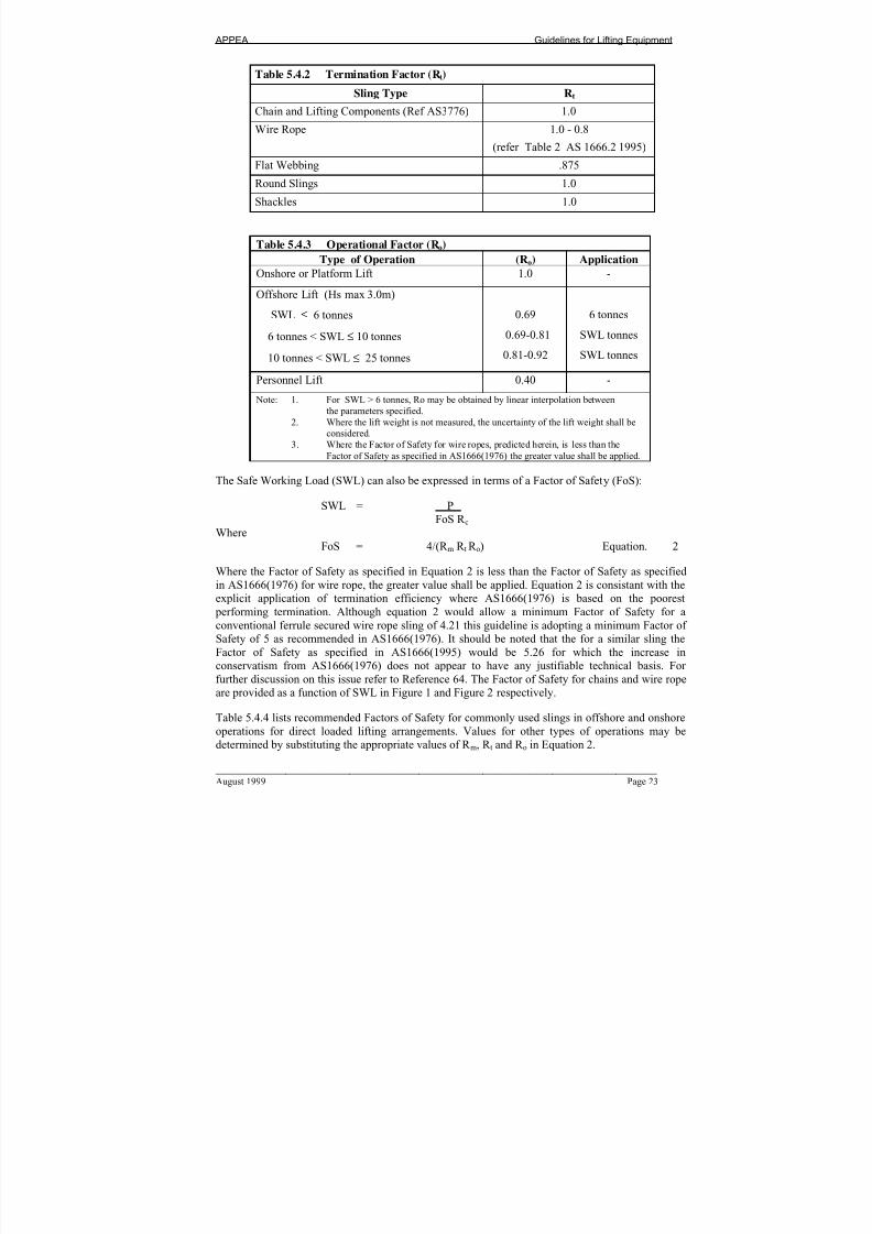
5.4 Design of Rigging
These guidelines vary the required factors of safety for rigging depending on whether the rigging is
to be used offshore or onshore. The dynamic factors of safety are based on findings of the field
study “Investigation of Dynamic Amplification Effects During Offshore Lifting” Reference 65.
Non-dynamic factors of safety are addressed in a discussion paper on “Factors of Safety for LiftingSlings used in Offshore Supply Boat Operations” Reference 64.
The following equation is based on a similar equation given in AS 1666.2 (1995) section 9 and
includes a material factor (R m) such that it can be used universally.
The SWL of a sling assembly shall be calculated from the equation:
SWL = (R c R m R t R o) x P Equation 1.
4 x 9.81
Where
SWL = Safe Working Load of the sling assembly (in tonnes)
P = Minimum Breaking Force for the individual rope (kN),chain or webbing which comprises the assembly
R c = Factor for Sling Assembly Configuration (refer Table 1 AS1666.2 (1995))
R m = Material Factor (refer Table 5.4.1 )
R t = Termination Factor (refer Table 5.4.2 )
R o = Operational Factor (refer Table 5.4.3 )
Table 5.4.1 Material Factor (Rm)Sling Type Rm
Chain and Lifting Components (Ref AS3776) 1.0
Wire Rope 1.0
Flat Synthetic Webbing Slings .57
Round Synthetic Slings .57
Shackles (Grades S&T Only) 0.80
7/24/2019 APPEA Lifitng and Rigging Guidelines
http://slidepdf.com/reader/full/appea-lifitng-and-rigging-guidelines 25/109
APPEA Guidelines for Lifting Equipment
____________________________________________________________________________ August 1999 Page 23
Table 5.4.2 Termination Factor (Rt)
Sling Type Rt
Chain and Lifting Components (Ref AS3776) 1.0
Wire Rope 1.0 - 0.8
(refer Table 2 AS 1666.2 1995)
Flat Webbing .875
Round Slings 1.0
Shackles 1.0
Table 5.4.3 Operational Factor (Ro)
Type of Operation (Ro) Application
Onshore or Platform Lift 1.0 -
Offshore Lift (Hs max 3.0m)
SWL ≤ 6 tonnes
6 tonnes < SWL ≤ 10 tonnes
10 tonnes < SWL ≤ 25 tonnes
0.69
0.69-0.81
0.81-0.92
6 tonnes
SWL tonnes
SWL tonnes
Personnel Lift 0.40 -
Note: 1. For SWL > 6 tonnes, Ro may be obtained by linear interpolation between
the parameters specified.
2. Where the lift weight is not measured, the uncertainty of the lift weight shall be
considered.3. Where the Factor of Safety for wire ropes, predicted herein, is less than the
Factor of Safety as specified in AS1666(1976) the greater value shall be applied.
The Safe Working Load (SWL) can also be expressed in terms of a Factor of Safety (FoS):
SWL = P
FoS R cWhere
FoS = 4/(R m R t R o) Equation. 2
Where the Factor of Safety as specified in Equation 2 is less than the Factor of Safety as specified
in AS1666(1976) for wire rope, the greater value shall be applied. Equation 2 is consistant with the
explicit application of termination efficiency where AS1666(1976) is based on the poorest
performing termination. Although equation 2 would allow a minimum Factor of Safety for a
conventional ferrule secured wire rope sling of 4.21 this guideline is adopting a minimum Factor of
Safety of 5 as recommended in AS1666(1976). It should be noted that the for a similar sling the
Factor of Safety as specified in AS1666(1995) would be 5.26 for which the increase in
conservatism from AS1666(1976) does not appear to have any justifiable technical basis. For
further discussion on this issue refer to Reference 64. The Factor of Safety for chains and wire rope
are provided as a function of SWL in Figure 1 and Figure 2 respectively.
Table 5.4.4 lists recommended Factors of Safety for commonly used slings in offshore and onshore
operations for direct loaded lifting arrangements. Values for other types of operations may be
determined by substituting the appropriate values of R m, R t and R o in Equation 2.

7/24/2019 APPEA Lifitng and Rigging Guidelines
http://slidepdf.com/reader/full/appea-lifitng-and-rigging-guidelines 26/109
APPEA Guidelines for Lifting Equipment
Page 24 August 1999
Table 5.4.4 Recommended Factors of Safety for Commonly Used Slings
Type of
OperationRo
Chain Sling
Rt= 1.0
Rm = 1.0
Wire Rope
Rt=0.95,
Rm =1.00
Flat Webbing
Rt=.875
Rm=.57
Round Webbing
Rt=1.0
Rm=.57
Onshore or
Platform lift1.00 4
5,
(Theoretical
value = 4.21)
8 7
Offshore Boat Lift(Hs=3.0m Max)
SWL <= 6
SWL = 10
SWL =25
0.69
0.81
0.92
5.8
5.0
4.4
6.1
5.2
5.0*
11.6
9.9
8.7
10.2
8.7
7.7
Note: 1. SWL in tonnes
2. Where the lift weight is not measured, the uncertainty of the lift weight shall be considered.
3. Where the Factor of Safety for wire ropes, predicted herein, is less than the Factor of Safety as
specified in AS1666(1976) the greater value shall be applied. *
Figure 1. Effective FOS for Chain Sling for “Offshore Boat Lifts”
Effective FoS - Chain
(Hs < 3.0m, Rt = 1, Rm = 1)
0
1
2
3
4
5
6
7
0 5 10 15 20 25
Safe Working Load (tonnes)
F a c t o r o f S a f e t y
APPEA (OFFSHORE)
AS3776 (ONSHORE)

7/24/2019 APPEA Lifitng and Rigging Guidelines
http://slidepdf.com/reader/full/appea-lifitng-and-rigging-guidelines 27/109
APPEA Guidelines for Lifting Equipment
____________________________________________________________________________ August 1999 Page 25
Figure 2. Effective FOS for Wire Rope Sling for “Offshore Boat Lifts”
(Ferrule Secured Terminations)
5.5 Access to Crane Hook for Marine crews – Fifth Leg Assemblies
Rigging assemblies should be of sufficient length to allow a rigger at ground or deck level to
connect the rigging assembly to the crane hook from the outside of the “Lifted Equipment”. During
lifting, the recommended included angle between the sling and the horizontal at padeye level is 60
degrees. Rigging assemblies with angles less than 45 degrees must be approved by the operator
prior to use. In some instances, consideration should be given to attaching a fifth leg to the top of
the assembly to ensure the top end of the rigging assembly can reach to within one metre of the
deck. Whilst the inclusion of a 5th leg will greatly assist supply vessel deck crews, it does delete the
inherent redundancy in a 4 leg assembly. For this reason a 4 leg assembly is preferred.
5.6 Diagonalling
For loads up to approximately 25 tonnes using 2, 3 and 4 point lifts, the total load should be taken
by 2 slings as required by AS 1666. Diagonalling effects should be considered for both “Lifted
Equipment” (including padeyes) and the rigging. (Not applicable to engineered lifts)
Effective FoS - Wire Rope
(Hs < 3.0m, Rt = 0.95, Rm =1)
0
1
2
3
4
5
6
7
0 5 10 15 20 25
Safe Working Load (tonnes)
F a c t o r o f S a f e t y
APPEA (OFFSHORE)
AS1666-1976 (ONSHORE)
7/24/2019 APPEA Lifitng and Rigging Guidelines
http://slidepdf.com/reader/full/appea-lifitng-and-rigging-guidelines 28/109
APPEA Guidelines for Lifting Equipment
Page 26 August 1999
5.7 Specific Requirements for Offshore Use
5.7.1 Synthetic Slings (Refer AS 1353.17.2-1997, AS 4497.1&.2 -1997)
It is recognised that there may be a need to use synthetic webbing slings and round slings for
offshore lifting of critical components. Synthetic slings should only be used where hard slings
would cause damage to the lifted load.
Factors of safety for both types of slings are given in Section 5. 4. Synthetic slings aremanufactured from nylon, polyester, polypropylene and Aramid Polyamide and their labels are
coloured green, blue, brown and yellow respectively. Only polyester (blue label slings are
considered suitable for offshore service.
Synthetic slings are more susceptible to damage than other types of slings and special procedures
should be developed for storage, inspection, identification, tagging and discard criteria.
Load testing requirements are covered in the above mentioned codes. It is generally accepted that
it is more economical to replace used slings than retest them, particularly in the smaller sizes.
5.7.2 Safety Shackles
It is preferred to use safety shackles rather than screw pin shackles. Where screw pin shackles are
used, the pins must be suitably seized using seizing wire. Plastic cable ties shall not be used to
secure pins. Shackles can be supplied as Grade S or Grade T. Generally Grade S shackles are
preferred.
5.7.3 Eyebolts
Eyebolts shall not be used for boat to facility or boat to boat lifts.
Prior to lifting using an eyebolt, the design of the eyebolt should be checked by a qualified
engineer. Refer to Clause 2.6 for competency requirements. All eyebolt lifts should be considered
as engineered lifts requiring approval.
An approved body should perform a thorough inspection of the eyebolts prior to lifts. Removal of
eyebolts for inspection should be considered. Refer to Clause 2.4 for competency requirement.
Eyebolts need not be included in registers except where the equipment is lifted on a regular basis.
5.7.4 Chain Slings
Chain slings manufactured from grade T chain (Australian Standard AS2321) have been
traditionally the preferred chain slings for offshore use. As a result of documented failures during
offshore lifts with chain slings manufactured using grade T chain, chain slings should comply with
the following guidelines.
• All new purchase of chain slings for offshore use shall specify chain slings to ISO 3076ISO 4778 or ISO 7593 until such time as Australian Standards are upgraded;
• Existing AS3775 slings using AS2321 grade T chain may still be used for lifts where there
is redundancy in the rigging arrangement (4 leg assemblies). They shall not be used for
single or two leg sling lifts where there is no redundancy.
Where chain slings are used for Offshore Lifting Operations a minimum chain size of 10mm shall
be adopted.

7/24/2019 APPEA Lifitng and Rigging Guidelines
http://slidepdf.com/reader/full/appea-lifitng-and-rigging-guidelines 29/109
APPEA Guidelines for Lifting Equipment
____________________________________________________________________________ August 1999 Page 27
5.8 Design of Offshore Container Padeyes & Their Attachment
Padeyes for “Lifted Equipment” up to a maximum weight of approximately 25 tonnes that are
intended for repeated use should be designed on the following basis:
• The dynamic amplification factor (DAF) is to be taken from the graph in Appendix D
based on the total lifted load.
• The “Design Load” shall be taken as the “Resulting Sling Force” (RSF) times the
appropriate DAF. The resulting sling load will take into account of the sling angle (apexangle of 60 degrees is common) and the diagonalling effects described in Clause 5.6.
• The load factor described in Clause 2.2 of AS1170/1 SAA loading code shall be taken as
1.0 on the basis that the maximum static load is known accurately.
• Padeye local capacity checks should be conducted using AS4100 “Steel Structures Code,”
Clause 7.5.
• A lateral load of 5% times RSF shall be applied concurrently with the RSF. The lateral
load shall be multiplied by the DAF. The lateral load shall be applied perpendicular to the
plane of the padeye at the height of the shackle pin centreline.
• The combined actions of the biaxial bending and tension should be checked using AS4100
“Steel Structures Code,” Clause 8.3.4.
The steel grade used for padeyes shall be clearly specified on the design drawings. It is recognised
that 350 grade is widely used but where padeyes are being checked on an existing container the
designer shall assume that grade 250 steel has been used unless justification for a higher grade
exists.
Hole sizes in padeyes should be equal to the shackle pin diameter plus 3mm or 4% greater than the
shackle pin diameter, whichever gives the larger hole. The thickness of the padeye should be at least
75% of the shackle width to avoid “twisting” the shackle. The maximum thickness of the padeye
shall be such that a total minimum gap of 5mm is maintained to avoid “binding”
5.9 Design of Lif ted Equipment (Offshore Containers)
“Lifted Equipment” consisting of structural steelwork such as: offshore containers skids, skips,
frames and bins which are intended for repeated use shall be designed in accordance with DNV 2.7-1.
The container shall be checked for two conditions as follows:
• 4 point in accordance with Clause 3.2.1.1 of DNV 2.7-1.
• 2 point lift in accordance with Clause 3.7.1.3 of DNV 2.7-1.
The allowable stress for both conditions is given in clause 3.2 of DNV 2.7-1. Structural designer’s
attention is also drawn to clause 3.2.3 of the DNV certification notes 2.7.1 regarding minimummaterial thickness.

7/24/2019 APPEA Lifitng and Rigging Guidelines
http://slidepdf.com/reader/full/appea-lifitng-and-rigging-guidelines 30/109
APPEA Guidelines for Lifting Equipment
Page 28 August 1999
Where a material other than structural steel is used, a design engineer should determine the
appropriate design standards and load factors.
5.10 Sea (ISO) Containers
Sea (ISO) Containers can be described as containers built for international shipping and are
designed to carry general purpose cargo internationally and interstate. They generally have “twistlock” type corner fittings for lifting with a purpose built frame. Sea (ISO) containers are not
specifically designed for use as offshore containers in operations associated with the offshore
petroleum industry.
Such containers intended to be used offshore should be load tested to the requirements of IMO
circular MSC 860.
It is recommended that the use of such containers be phased out as soon as possible. A target date of
December 31st 2000 has been set for the complete phase out of ISO containers. Contractors are
advised to check with individual operators for their requirements with respect to the phase out of
ISO shipping containers. During the transition period, the following guidelines should apply to their
use as offshore containers:
• They should not be loaded above 40% of their ISO MGW rating and load tested in
accordance with Section 7;
• All lifting should be conducted using padeyes. Twist lock fittings shall not be used for
lifting;
• There should be trace-ability of the material used for padeyes fitted to the container and of
all welding carried out on the container;
• Closed and open top ISO containers greater than 20 feet (6.4 metres) in length should not be used offshore. Open top ISO containers should not be used as offshore containers;
• Prior to any intended offshore use, thorough inspections should be carried out on the
container’s floor support members and door latching mechanisms. These are critical to the
container’s integrity;
• Inspections should be conducted by competent persons. Refer to clause 2.4.2 for
competency requirements;
• Forklift pockets shall only be used for onshore lifting;
Prior to the container phase out date, inspection and testing of ISO shipping containers used in the
offshore oil and gas industry should be performed according to the APPEA ‘Guidelines for the
Phase Out of ISO Shipping Containers’ (Refer Appendix H).

7/24/2019 APPEA Lifitng and Rigging Guidelines
http://slidepdf.com/reader/full/appea-lifitng-and-rigging-guidelines 31/109
APPEA Guidelines for Lifting Equipment
____________________________________________________________________________ August 1999 Page 29
5.11 Design of Sub-sea Lif ts
Sub-sea lifts are a specialised form of lift the design of which should only be undertaken by
qualified engineers with experience in this area. Generally, the design of “Lifting Equipment”
should follow the same approach as that for a similar lift in air. Sub-sea “Lifting Equipment” should
be designed in accordance with “DNV Marine Operations, Part 2 Chapter 6 - Sub-Sea Operations”
or a recognised equivalent. The lift design should take into account factors specific to the offshore
environment in which the lift is being conducted. As a minimum, consideration should be given tothe following factors associated with subsea lifts, many of which are highly dependent on the shape
of the equipment being lifted.
• Viscous drag due to diversion of water around the “Lifted Equipment” (noting that velocityof equipment in water = winch velocity plus angular velocity due to vessel roll);
• Apparent additional inertia due to the “Lifted Equipment” accelerating the surroundingfluid. (commonly referred to as the added mass);
• Reduced mass of the “Lifted Equipment” in water due to buoyancy;
• Near surface and near seabed stability due to the vibration absorption/amplification of thesurrounding fluid.
• When the “Lifted Equipment” is at or just above the air/water interface, allowing for themass of the water to be temporarily supported when waves break over the equipment;
• Increased mass due to marine growth and entrapped sediments when retrieving “Lifted
Equipment”;
• Suction when lifting off the sea bed;
• When in water, force due to the apparent additional inertia from accelerated water = mass of water x g x (DAF - 1.0)
• Force due to equipment, marine growth and sediments= mass of items in water x g x DAF).
As the hook of the “Lifting Device” will rise and fall in the water due to vessel roll, rigging for
“Lifted Equipment” needs to be of sufficient length to avoid the hook striking divers, ROV”s and
other sub-sea equipment in the vicinity of the lift. Padeyes and rigging should be of a suitable
colour and of sufficient size to enable easy location and use by divers or ROV’s.
Many of the above factors can be reduced by the use of specialised equipment and techniques.
When a self-compensating winch or other line load control system is used, the effects of vessel roll
on dynamics and velocity in water may be reduced. When an item is lifted off the sea bed, suction
effects can be reduced by sliding before raising. Excessive mass due to marine growth and
entrapped sediments may be removed prior to lifting.
The above factors cannot be avoided by assuming motion of the “Lifted Equipment” is always
downward, as any requirement to stop lowering prior to placement, either planned or in emergency,
may result in their occurrence.

7/24/2019 APPEA Lifitng and Rigging Guidelines
http://slidepdf.com/reader/full/appea-lifitng-and-rigging-guidelines 32/109
APPEA Guidelines for Lifting Equipment
Page 30 August 1999
5.12 Materials of Construction and Fabrication Requirements
Fabrication of “Lifting Equipment” shall be in accordance with recognised international or
Australian standards.
All materials should be suitable and safe for their intended purpose; for the fabrication, transport,
installation and use of “Lifting Equipment”; and to comply with the requirements for materials in
nominated Australian or international standards. Particular attention should be paid to the fracture
toughness of materials.
Vendors and fabricators should have quality management systems equivalent to ISO9001, ISO9002
or ISO9003. All materials used in the fabrication of “Lifting Equipment” shall have documentation
in accordance with the contractor’s quality control procedures to demonstrate trace-ability. As
applicable, some or all of this documentation may be required to support the equipment register.
5.13 Documentation – New Build Lifted Equipment
All “Lifted Equipment” should be issued with a Certificate of Conformity prior to their initial proof
load testing. This must be issued by one of the following bodies, either as a separate document or asa dedicated section included on the Load Test Certificate and must be signed by an endorsed
signatory of either of the following:
• Classification societies with accepted design standards for offshore “Lifted Gear” (e.g.DNV);
• A “body” holding NATA accreditation for design verification of Offshore “Lifted Gear” to
these guidelines;
The Certificate of Conformity should contain the following information:
• Assurance that the lifted item (container) has been designed, fabricated and tested tooffshore “Lifting Equipment standards (e.g. DNV or other). The owner of the equipment
shall retain the certificate;
• Containers that are required to comply with the International Maritime Dangerous Goods
(IMDG) regulations, should also be certified in accordance with the IMDG code.
The certificate of conformity shall be based on the following documentation collated in an “as
built” dossier, which shall be retained by the owner:

7/24/2019 APPEA Lifitng and Rigging Guidelines
http://slidepdf.com/reader/full/appea-lifitng-and-rigging-guidelines 33/109
APPEA Guidelines for Lifting Equipment
____________________________________________________________________________ August 1999 Page 31
• Structural calculations;
• Drawings;
• Specifications for welding procedures;
• Welder qualifications;
• Material certificates;
• Report on trace-ability of materials;
• Report from fabrication inspection;
• Report from non-destructive examination;
• Report from prototype testing;
• Report from proof testing;
• Report from final inspection;
The certificate of Conformity shall contain the following information:
• Container fabrication number;
• The Certificate number;
• Description of the container including;
• External dimensions;
• Number of lifting points;
• Name of fabricator;
• Date of fabrication;
• Maximum gross weight in kilograms;
• Tare weight in kilograms;
• Net weight in kilograms;
• Reference to the “as built” dossier;
• The total gross weight in kilograms applicable to the all points lifting test and the actual
method of test;
• Specification of lifting set;
• Angle of legs (from horizontal);

7/24/2019 APPEA Lifitng and Rigging Guidelines
http://slidepdf.com/reader/full/appea-lifitng-and-rigging-guidelines 34/109
APPEA Guidelines for Lifting Equipment
Page 32 August 1999
• Shackle bolt diameter;
• Required safety factor (against breaking);
• Conformity to other requirements and codes;
• A statement that the container has been designed, fabricated and tested in accordance with
this guideline;
• Remarks;
• Signature on behalf of the certifying body.
Proprietary devices and “Lifted Equipment”, such as drum lifters, plate clamps, etc, should be
accompanied by schematic drawings and a maintenance and operating manual and should only be
used for onshore and on platform lifts.
“Lifted Equipment” may be type or batch tested where required by Australian or international
standards. Evidence of type testing status (in the form of third party certification) shall always be
sought for new equipment. Examples of “Lifting Equipment” requiring type testing to destruction to
Australian Standard are as follows:
• Serial hoists and winches AS 1418.2
• Flat synthetic webbing slings AS 1353
• Eyebolts AS 2317
• Synthetic round slings AS 4497 parts 1 & 2
5.14 Documentation for Existing Lif ted Equipment
It is recommended that a certificate of conformity be issued for existing “Lifted Equipment” by
December 31, 2000 or the next due date for periodic load testing which ever is the sooner. The
minimum requirement to enable a certificate of conformity to be issued for existing “Lifted
Equipment” are as follows:
• Existing “Lifted Equipment” is inspected in accordance with Section 8 and Appendix I
and found to have passed the certified visual inspection and NDT where appropriate (eg.
padeyes).
• Padeye designs should be reviewed by an experienced Engineer 1 to ensure compliancewith clause 5.8. Where padeyes do not meet this standard they should be modified
appropriately.
• The design of the container has been reviewed by an experienced Engineer 2. The review
should confirm that the item of “Lifted Equipment” has sufficient structural integrity to
pass load tests specified in Table E.2.
1 Refer to Clause 2.6 for competency requirements
2 Refer to Clause 2.6 for competency requirements

7/24/2019 APPEA Lifitng and Rigging Guidelines
http://slidepdf.com/reader/full/appea-lifitng-and-rigging-guidelines 35/109
APPEA Guidelines for Lifting Equipment
____________________________________________________________________________ August 1999 Page 33
• Load testing of “Lifted Equipment” is conducted by an appropriate body in accordance
with Table E.2.
• Load testing of rigging is conducted by an appropriate body in accordance with Table
E.3.
• Rigging shall meet the requirements of Appendix C, where existing rigging is retained
some reduction in the maximum SWL will be required.
5.15 Initial Load Tests (Offshore Containers including ISO Containers)
When new containers are built or containers being put back into service after a major repair or
modification or are being put into offshore service for the first time, they shall be load tested by an
appropriate body. The accrediting body may request a drop test of containers when verifying adesign for the first time. Refer to Clause 2.5.1 for competency requirements.
The following points should be observed:
• In the case of Sea (ISO) Containers the internal test load is to be based on the maximum
gross mass (MGM) determined in accordance with Section 5.10. For purpose built
containers, the MGM identified on the container’s identification plate should be used.
e.g.
MGM = 9.6 Tonnes,
Tare = 2.5 TonnesTest load For 4 point lift = (2.5 x 9.6) - 2.5 = 21.5 Tonnes
(to be placed in the container)
• Precautions should be taken when securing test loads, particularly for a 2 point lifting test.
Where a large number of identical containers are manufactured, guidance on the number to be
tested is given in DNV Certification Notes 2.7-1 Section 4.
The container shall be considered to have passed the initial load test provided there is no permanent
deformation of the container. Deformation can readily be measured using two taut wires strung
between the diagonal corners of the container.Where proof loading is not a viable option, (i.e. where access for loading is restricted such as for
transportable buildings with small doorways) structural assessment of the container may be
determined by a certified visual inspection. The certified visual inspection of the container shall be
conducted by an appropriate body. Refer to Clause 2.4.2 for competency requirements.
5.16 Non Destructive Testing (Offshore Containers including ISO Containers)
NDT at fabrication shall include inspection of the lifting points (padeyes) and the connections
immediately adjacent to the lifting points as a minimum.Consideration should also be given to the NDT inspection of all primary members and their
connections.

7/24/2019 APPEA Lifitng and Rigging Guidelines
http://slidepdf.com/reader/full/appea-lifitng-and-rigging-guidelines 36/109
APPEA Guidelines for Lifting Equipment
Page 34 August 1999
NDT inspection shall be conducted by an appropriate body. Refer to Clause 2.5 for competency
requirements.
7/24/2019 APPEA Lifitng and Rigging Guidelines
http://slidepdf.com/reader/full/appea-lifitng-and-rigging-guidelines 37/109
APPEA Guidelines for Lifting Equipment
____________________________________________________________________________ August 1999 Page 35
6 DESIGN OF TANKS FOR FLUIDS
Tank design shall conform to relevant sections of:
• AS 1692 ‘Tanks for Flammable and Combustible Liquids’
• AS/NZ 3711.6 ‘Tank Containers’
• IMDG Code
• DNV 2.7-1 ‘Offshore Containers’
• ISO 1496-3 ‘Freight Containers – Specification and Testing’
• prEN 12079 ‘Offshore Containers – Design, Construction, Testing, Inspection
and Marking’
The APPEA guidelines for offshore tanks for fluids coincide with the requirements of DNV 2.7-1,
section 3.5 and prEN12079, section 5.5.3.
The following is an extract from prEN12079:
“Tanks for dangerous cargoes shall fulfil the requirements of the IMDG Code and shall be
designed according to recognised rules for pressure vessels. A tank and its support shall be
able to withstand lifting and impact loads. In addition, due account shall be taken of fluid
surge arising from partly filled tanks.”
Note: Chapter 13 of the general introduction to the IMDG Code does not allow tanks with a lengthabove 3m to be handled by forklift in a loaded condition. Special protection of the tank and fittings
in the area near the fork pockets is required.
On tank containers for dangerous cargoes, all parts of the tank and fittings shall be suitably
protected from impact damage by a frame, suitable for offshore service where applicable. In
addition to the IMDG Code, the following shall apply:
• Beams, plates or grating, shall protect the top of the tank and its fittings. No part of the
tank or its fittings shall extend above a level 100mm below the top of the framework. It
shall not be possible for any part of the lifting set to foul fittings, manhole cleats or other
protrusions on the tank.
• Protective beams shall be placed at or near the location where the tank shell is nearest to
the outer plane of the sides. Beams shall be spaced sufficiently close together to give the
necessary protection.
• At the maximum calculated elastic deflection of any side member, the residual clearance
between the member and any part of the tank shell or its fittings shall be at least 10mm.
• No part of the underside of the tank shell (including sumps), the bottom valves or other
fittings shall extend below a level 150mm above the bottom of the framework. Any such
part extending below a level 300mm above the bottom of the framework shall be protected by beams or plating.

7/24/2019 APPEA Lifitng and Rigging Guidelines
http://slidepdf.com/reader/full/appea-lifitng-and-rigging-guidelines 38/109
APPEA Guidelines for Lifting Equipment
Page 36 August 1999
• Tank containers designed with direct connection between the tank and the side or top frameelements shall be subject to special consideration by the operator or during operation to
avoid damage.

7/24/2019 APPEA Lifitng and Rigging Guidelines
http://slidepdf.com/reader/full/appea-lifitng-and-rigging-guidelines 39/109
APPEA Guidelines for Lifting Equipment
____________________________________________________________________________ August 1999 Page 37
7 MARKING OF LIFTING EQUIPMENT
7.1 General
All “Lifting Equipment” shall be marked with an individual identification code (“Unique Number”)
and the safe working load (SWL) as determined from the design. Where appropriate, for certain
“Lifted Equipment”, the SWL may be replaced by the tare and gross. The identification code shall
enable the operator to link the manufacturer and test certification numbers. For contractor owned
equipment, this code should include unique character(s) or colour to indicate the owner.
If the use of an item of “Lifting Equipment” is restricted to certain types of operations, this shall be
marked on the item. For example, a spreader beam which has been designed for onshore use, shall
be marked, “ONSHORE USE ONLY; NOT FOR OFFSHORE BOAT LIFTS”
7.2 Marking of Lif ting Devices
7.2.1 Fixed Location Padeyes
Valid certified padeyes which have undergone proof loading (to Marine Orders 32 requirements as
a minimum) and non destructive testing should be identifiable at point of location with the padeye
centrally positioned in a 30 cm x 30 cm black painted square (minimum size). The SWL and the
identification number should be stenciled in white within the black square.
7.3 Marking of Lif ted Equipment
“Lifted Equipment” including equipment containers, skips, baskets, frames and similar items are
expected to be marked with the information as shown on examples of marking plates provided inAppendix E or a similar alternative.
All characters marked on the container (e.g. Tare, Nett and Gross) should be durable, of
proportionate width and thickness and in a colour contrasting with that of the container. The
markings should be clearly legible and, if painted, stenciled.
Manufacturer’s plates should be of a suitable size for the required information as indicated in
Appendix E and should be of durable material (such as stainless steel) and securely fixed in a
visible but protected location.
Inspection & test plates should be of a suitable size as indicated in Appendix E, should. The plates
should be updated or replaced when either load testing, NDT or certified visual inspection is carried out.
Containers and tanks used for dangerous cargoes should be marked according to the requirements of
the IMDG Code, in addition to the marking requirements of this Section.
7.4 Container and Roof Identification Markings
Each container should be marked with a container number issued by the owner as a unique
identification, which should be the common cross-reference on all in service certification, shipping
documentation, etc.
The container number shall be prominently displayed on all sides of the container (as viewed from
ground level) in characters of contrasting colour, not less than 75 mm high.

7/24/2019 APPEA Lifitng and Rigging Guidelines
http://slidepdf.com/reader/full/appea-lifitng-and-rigging-guidelines 40/109
APPEA Guidelines for Lifting Equipment
Page 38 August 1999
If the container has a roof, the container number should be displayed on the roof, in characters not
less than 300 mm high (or less if space is limited). The marking should be carried out in such a way
as to avoid incorrect interpretation (e.g. by underlining). Where applicable, the lower edge marking
should be positioned near the side of the container in which the door is located.
7.5 Lif ting Frame and Beam MarkingsThe minimum marking required for each lifting frame and lifting beam should include ID No,
TARE and SWL. The marking should be done using 50 mm letters. Where required, the design
approval number allocated by the relevant Statutory Authority should be added. Where no suitable
location exists, painted markings down to 25 mm, on a securely fixed plate are acceptable. Stamped
markings should not be less than 8 mm in height.
7.6 Marking of Rigging
The appropriate Australian Standards provide all marking details for rigging. Wire rope riggingassemblies shall be tagged in accordance with AS1666.1 Section 7. Chain rigging assemblies shall
be tagged in accordance with AS3775 Section 8.
7/24/2019 APPEA Lifitng and Rigging Guidelines
http://slidepdf.com/reader/full/appea-lifitng-and-rigging-guidelines 41/109
APPEA Guidelines for Lifting Equipment
____________________________________________________________________________ August 1999 Page 39
8 PERIODIC INSPECTION, TESTING AND MAINTENANCE
8.1 General
The periodic inspection, testing, and maintenance (including repairs) of all “Lifting Equipment”,
including contractor owned, shall be conducted by competent, qualified personnel accredited to
these guidelines by NATA or a Classification Society with industry accepted standards in the
inspection, testing and maintenance of “Lifting Equipment”. (Refer Sections 2.4–2.6 for
competency requirements) Periodic inspection, testing and maintenance shall be conducted in a
manner to ensure safety to people and plant. When requested, contractors are expected to supply the
operator with, copies of all relevant certificates before the “Lifting Equipment” is used at any
location under the operator’s jurisdiction.
A specific inspection, maintenance and testing plan should be developed for each “Lifting Device”,
each item of “Lifted Equipment” and rigging assembly or item. Where a safety case is in place this
plan should be risk based and developed in accordance with the appropriate safety case guidelines.
The inspection, testing and maintenance plan should consider the following factors:
• Manufacturer’s recommendations;
• Statutory requirements;
• Relevant historical data;
• Frequency of use;
• Operational environmental conditions.
The plan should address:• Periodical inspection and maintenance routines (e.g. weekly, annual);
• A feedback loop to allow modifications to routines based on performance;
• Procedures for documenting results of inspections and tests;
• Procedure for colour coding inspected and tested equipment;
• Inspector’s responsibility and qualification matrix.
Records of testing, inspection, maintenance, repair and modification should be included in the
“Lifting Equipment” Register.
All “Lifting Equipment” shall be visually checked prior to each use by appropriately certified crane
driver, dogger or rigger (as applicable). This inspection should ensure that:
• Equipment is appropriate for load to be applied;
• Equipment is in good condition;
• Equipment is correctly labeled;
• Equipment for onshore use is not being used offshore.

7/24/2019 APPEA Lifitng and Rigging Guidelines
http://slidepdf.com/reader/full/appea-lifitng-and-rigging-guidelines 42/109
APPEA Guidelines for Lifting Equipment
Page 40 August 1999
Non complying equipment shall be tagged and either removed from site or repaired.
Scheduled testing and inspections should include test loading, non-destructive testing (NDT) and
visual inspection (as appropriate). Recommended inspection and testing frequencies are provided in
Appendix F.
Variations to these recommended frequencies are acceptable where a reliability based approach is in
place under a facility’s safety case.
8.2 Lif ting Devices
8.2.1 Inspection Before and After Proof Loading
For “Lifting Devices” and associated rigging, inspection should be performed in accordance with
the Australian Standards.
For equipment not covered by Australian Standards, the equipment owner in conjunction with the
inspector should select the most appropriate of those inspection requirements provided in AS 1418for “other devices”.
For specially fabricated devices such as overhead padeyes, the requirements for “Lifted Equipment”
should be applied.
8.3 Lif ted Equipment
The following requirements for inspection apply to “Lifted Equipment”. Note that these
requirements are based on DNV recommendations for periodic inspection of “Lifted Equipment”.
These requirements are guidelines for inspection or repair organisations to develop their owndetailed work instructions or procedures. These requirements should be subject to the equipment
owner and/or users approval.
All “Lifted Equipment” should be periodically inspected by an appropriate body. Refer to Clause
2.4.2 for competency requirements.
The inspection should meet the following requirements:
• Prior to testing, key dimensions and straightness should be measured;
• Structure should be visually examined for corrosion, mechanical damage and injurious
deformation;
• All accessible load bearing welds should be visually examined to ensure freedom from
defects;
• The lifting points should be visually examined for distortion, mechanical damage or any
other sign of distress or overload;
• Doors, frames, seals, hinges, locks etc. should be visually examined and functionallychecked to ensure that they operate in a satisfactory manner without undue force being
required;

7/24/2019 APPEA Lifitng and Rigging Guidelines
http://slidepdf.com/reader/full/appea-lifitng-and-rigging-guidelines 43/109
APPEA Guidelines for Lifting Equipment
____________________________________________________________________________ August 1999 Page 41
• The floor should be visually examined to check that it is substantially flat with no sign of
distress or overload. Drainage facilities, where fitted should be examined, e.g. drain holes
should be clear of debris etc.;
• The paint markings and plates should be checked to see that they meet the
recommendations of this document;
• Inspect lifting set for: rating, condition, currency of test etc.;
• If due or required proof load test. (Proof load test to be conducted prior to NDT);
• After completion of a proof test load, the equipment should be re-examined for signs of
permanent deformation caused by the test. Any deformation or weld defect caused by the
load test shall result in the withdrawal of the equipment from service until all such faults
have been corrected and a further satisfactory load test completed;
• NDT by the method nominated on the drawings if due, or required;
• Welds to all padeyes and members directly supporting padeyes should be subject to 100%
magnetic particle inspection (MPI);
• Where it is determined that a fault is related to design or fabrication quality, a
modification or repair method shall be developed, and approved by the responsible
person, before commencement of any rectification works;
APPEA detailed guidelines for the inspection, testing and marking of offshore containers are
provided in Appendix I.

7/24/2019 APPEA Lifitng and Rigging Guidelines
http://slidepdf.com/reader/full/appea-lifitng-and-rigging-guidelines 44/109
APPEA Guidelines for Lifting Equipment
Page 42 August 1999
8.4 Rigging
8.4.1 Proof Loading of Rigging used for Offshore Lifting (Boat Lifts)
The rigging for the “Lifted Equipment” shall be subject to a proof force that is not less than 50% of
the rated minimum breaking load (MBL) of the member.
Proof Load = 50% x R t x R m x MBL,
Where R t and R m are defined in section 5.4
Where all the components of the sling have been proof tested, but any component has been subject
to further processing subsequent to any further earlier proof testing, the rigging shall be subject to
further proof testing.
The sling shall withstand the application of the proof force, without sustaining damage that may
affect its intended function or safety. The sling shall also be free from any deleterious permanent set
or defects visible to the unaided eye.
Proof load testing of rigging and NDT testing as appropriate shall be conducted by an appropriate
body. Refer to Clause 2.5 and 2.5.1 for competency requirements.
8.5 Repairs and Modifications to Lifting Equipment
Repairs and modifications to “Lifting Devices” should be carried out to conform with the original
manufacturer’s specification and in accordance with Section 4. For “Lifted Equipment” where it is
not clear whether a member is structural or not, guidance should be sought from a qualified design
engineer. Design changes that alter the original structural details or safe working load capabilities of the “Lifting Equipment” should be approved by a qualified design engineer. Refer to clause 2.6 for
competency requirements.
“Lifting Equipment” shall be proof load tested following repairs involving modifications or heat
application to structural members.
All repairs or modifications should be recorded in the “Lifting Equipment” Register (Section 3).

7/24/2019 APPEA Lifitng and Rigging Guidelines
http://slidepdf.com/reader/full/appea-lifitng-and-rigging-guidelines 45/109
APPEA Guidelines for Lifting Equipment
____________________________________________________________________________ August 1999 Page 43
9 SAFE OPERATING PROCEDURES
9.1 Lif ting Operations between Platforms and Vessels
9.1.1 Planning
The Australian Offshore Support Vessel Code of Safe Working Practice provides guidance on
lifting operations between platforms and vessels.
The safe conduct of lifting operations involving the transfer of cargo between a platform and a
vessel require planning and a high level of communications among the parties involved in these
operations.
Prior to the start of any lifting operations, the communications between the person in charge of the
facility and the Master of the vessel, or their appointed deputies, should address the following
issues:
• The suitability of existing and forecast weather conditions for the required lifting
operations involving the vessel;
• Communications arrangements between the facility and the vessel during the liftingoperation;
• Any limitations or restrictions affecting, or which may interrupt, the proposed operations;
• The nature and weights of the cargo to be transferred and any special lifting requirements;
• Whether any of the proposed lifts require special consideration, safeguards or controls
during lifting, or special securing arrangements on the vessel;
• Rigging arrangements to be used and any special rigging requirements;
• Procedures to be used in the event of an emergency occurring while lifting operations are being conducted.
9.1.2 Communications
Safe lifting operations rely on there being effective communications among the Master of the
vessel, the person in charge of the facility, the crane operator, the deck officer in charge on the
vessel and the deck crews on both the facility and the vessel. A reliable radio communication link
on a dedicated channel or frequency should be maintained throughout the operations. The crane
operator on the facility should have direct radio communication with the vessel.
The crane operator should have a clear view of the deck areas on both the facility and the vessel.
Where this is impractical, a dogger should be so stationed as to have a clear view of the deck area to
assist the crane operator. Directions given to the crane operator by the deck crew on the vessel must
only be given by one person who has been clearly identified for that purpose.

7/24/2019 APPEA Lifitng and Rigging Guidelines
http://slidepdf.com/reader/full/appea-lifitng-and-rigging-guidelines 46/109
APPEA Guidelines for Lifting Equipment
Page 44 August 1999
9.1.3 Lif t Preparation and Handl ing
Wherever practicable, all lifts should be pre-slung using rigging which conforms to these
guidelines. Rigging should allow the deck crew to connect / disconnect the lift at deck level.
Open cargo baskets containing loose materials should be provided with safety nets or covers to
prevent discharge of the contents during lifting operations or while in transit. Doors and lids on
closed containers must be securely fastened.
No container should be loaded in excess of its rated capacity. Material should not be added to
containers, skips, cargo baskets, etc already transferred to the deck of a vessel unless it is safe to do
so, the capacity of the container will not be exceeded, and the change to the loading is recorded on
the manifest.
9.2 Personnel Transfers
Personnel baskets should only be used in emergency or in other circumstances where the use of
alternative means of transferring personnel is impractical or unsafe. They should only be carried out
under the authority of the person in charge of the facility and with the agreement of the personnel being transferred and the master of the vessel involved.
Each facility should have documented procedures for this type of operation. These procedures
should address the issues identified in these guidelines.
9.2.1 Authority
The person having the authority to approve personnel basket transfers should be clearly identified.
Approval should not be given unless this person is satisfied that the personnel involved agree to the
transfer operations and the transfer can be safely carried out.
9.2.2 Duties
The duties of personnel in supervising or carrying out the personnel basket transfer should be
clearly defined. Generally, this would include the person in charge of the facility, the crane
operator, the Master of the vessel, and other people nominated by the person in charge and the
Master of the vessel to undertake specific duties.
The Person in charge of the facility should:
• be aware of the reason for the transfer;
• be satisfied with the fitness and training of the people to be transferred;
• be satisfied as to the suitability of the vessel;
• know the limitations of visibility and sea state;
• be aware of the limitations on transfer by night;
• be aware of the suitability of the crane for personnel transfer;
• check the wind speed limitations on crane operations;
• establish satisfactory communications with the Master of the vessel involved in the
transfer;
• ensure that participants understand the procedures involved;

7/24/2019 APPEA Lifitng and Rigging Guidelines
http://slidepdf.com/reader/full/appea-lifitng-and-rigging-guidelines 47/109
APPEA Guidelines for Lifting Equipment
____________________________________________________________________________ August 1999 Page 45
• be satisfied with the competence and experience of the crane
driver;
• be satisfied with the inspection and testing of the personnel basket.
The Master of the vessel should confirm to the person in charge of the facility that:
• the transfer has been accepted and the procedures have been understood;
• the vessel has a satisfactory station keeping capability;
• the deck crew have been fully briefed;
• the people to be transferred have been adequately briefed and are fit to
be transferred.
The crane operator should ensure that:
• the crane is fully operational;
• the wind speed is satisfactory for safe operation;
• the requirements and procedures involved are clearly understood;
• the dogger and the transfer area are clearly visible;
• adequate communications have been established.
The dogger and deck supervisor should ensure that:
• the transfer procedure is understood;
• they are clearly identifiable as dogger and deck supervisor.
• the personnel basket is correctly used;
• the transferees are fit for transfer and understand the procedures;
• proper communications have been established;
• respectively they have a full view of the transfer areas.
Individuals who are to be transferred should:• ensure that they understand the transfer procedure;
• confirm that they are agreeable to the transfer;
• be able to use correctly the safety equipment provided;
• observe all instructions from those in charge of the operation.
9.2.3 Suitabil ity of the vessel
The type of vessel considered suitable to carry out a transfer should be determined by its ability tomaintain station alongside the facility and have sufficient clear deck space to safely receive the
basket.

7/24/2019 APPEA Lifitng and Rigging Guidelines
http://slidepdf.com/reader/full/appea-lifitng-and-rigging-guidelines 48/109
APPEA Guidelines for Lifting Equipment
Page 46 August 1999
9.2.4 Weather conditions
Weather conditions are critical factors impacting on the safety of personnel basket transfers. Factors
which should be taken into account include visibility, wind and sea state. Guidelines should be
provided which specify the maximum wind speed and sea state beyond which basket transfer is not
permissible, including the wind speed limitations for crane operations and the effect of weather
conditions on the stability of the vessel.
9.2.5 Communications
Both radio and visual communication should be established and maintained between those
personnel conducting the operation.
9.2.6 Safety equipment and rescue procedures
The procedures should specify the type of safety equipment to be worn by personnel beingtransferred and the rescue arrangements made. Personnel being transferred should wear life-jackets,
suitable clothing and other specified safety equipment. Life-jackets should be equipped with
suitable means of illumination during night transfers. The standby vessel should be in close
attendance during transfer, with the rescue boat ready for immediate launching.
9.2.7 Training
Personnel will be transferred by basket in greater safety and with less apprehension if they, and the
personnel conducting the transfer, have received training in the techniques involved. The type of
training required can be included in installation drills. Inexperienced people or those not trained inthe use of personnel baskets should always be accompanied by someone who has been trained in
personnel transfer procedures.

7/24/2019 APPEA Lifitng and Rigging Guidelines
http://slidepdf.com/reader/full/appea-lifitng-and-rigging-guidelines 49/109
APPEA Guidelines for Lifting Equipment
____________________________________________________________________________ August 1999 Page 47
APPENDIX A
REFERENCE DOCUMENTS
7/24/2019 APPEA Lifitng and Rigging Guidelines
http://slidepdf.com/reader/full/appea-lifitng-and-rigging-guidelines 50/109
APPEA Guidelines for Lifting Equipment
Page 48 August 1999
LEGISLATION
1. Petroleum (Submerged Lands) Act 1967 [PSLA]
2. Petroleum (Submerged Lands) Acts: Schedule of Special Requirements as to Offshore
Petroleum Exploration and Production
3. Navigation Act 1912 and associated Regulations and Marine OrdersMO Part 32 “Cargo Handling Equipment and Safety Measures”
MO Part 44 “Safe Containers”
4. Explosives and Dangerous Goods Act
5. Occupational Health, Safety and Welfare Act
6. WA: Occupational Safety and Health Act 1984 and Associated Regulations 1996
7. NT: Work Heath Act 1992
8. NT: Work Health - Occupational Health and Safety Regulations 1992
AUSTRALIAN AND NEW ZEALAND STANDARDS ETC.
9. AS ISO-1000 The International System of Units and its Application
10. AS 1138 Thimbles for Wire Rope
11. AS 1171 Non-Destructive Testing Magnetic Particle Testing of Ferromagnetic
Products, Components and Structures
12. AS 1163 Structural Steel Hollow Sections
13. AS 1353 Flat Synthetic Webbing Slings
14. AS 1380 Fibre Rope Slings
15. AS 1418 Cranes (Including Hoists and Winches)
16. AS 1438 Wire - Coil Flat Slings
17. AS 1504 Fibre Rope – Three Strand Hawser Laid
18. AS/NZS 1554 Structural Steel Welding
19. AS 1650 Hot-Dipped Galvanised Coatings on Ferrous Articles (superceded in part by
AS/NZS 4534 but remains current)
20. AS 1657 Fixed Platforms, Walkways, Stairways, Ladders,
21. AS 1664 Aluminium Structures
22. AS 1666 Wire Rope Slings
23. AS 2068 Flat Pallets for Materials Handling
24. AS 2076 Wire Rope Grips for Non-Lifting Applications
25. AS 2089 Sheave Blocks for Lifting Purposes
26. AS 2207 Non-Destructive Testing for Ultrasonic Testing of Fusion Welded Joint in
Carbon and Low Alloy Steel27. AS/NZS 2312 Guide to the Protection of Iron and Steel against Exterior Atmospheric
Corrosion
28. AS 2317 Collared Eyebolts
29. AS 2318 Swivels for Hoists
30. AS 2319 Rigging Screws and Turnbuckles
31. AS 2321 Short Link Chain for Lifting Purposes (Non Calibrated)
32. AS 2550(1982) Cranes - Safe Use
33. AS 2741 Shackles
34. AS 2759 Steel Wire Rope - Application Guide
35. AS 3569 Steel Wire Ropes
36. AS/NZS 3678 Structural Steel - Hot Rolled Plates, Floor Plates and Slabs37. AS/NZS 3679.1 Structural Steel - Part 1: Hot Rolled Bars and Sections
38. AS/NZS 3679.2 Structural Steel - Part 2: Welded I Sections
39. AS 3775 Chain Slings - Grade T

7/24/2019 APPEA Lifitng and Rigging Guidelines
http://slidepdf.com/reader/full/appea-lifitng-and-rigging-guidelines 51/109
APPEA Guidelines for Lifting Equipment
____________________________________________________________________________ August 1999 Page 49
40. AS 3776 Lifting Components for Grade T Chain Sling
41. AS 3777 Shank Hooks and Large Eye Hooks - Maximum 25 Tonne
42. AS 3990 Mechanical Equipment – Steelwork
43. AS 4048 Flat Pallets for Materials Handling (1100mm x 1100mm Suitable for use in
ISO Series 1 Freight Containers)
44. AS 4100 Steel Structures
45. AS 4142 Fibre Rope
46. AS 4497 Roundslings - Synthetic Fibre, Parts 1 & 247. AS B291 Lifting Rings & Links
48. AMSA Marine Orders part 44
49. AMSA Marine Orders part 32
50. AS/NZS 3711 Freight Containers
INTERNATIONAL STANDARDS
46. BS 2573 Rules for the Design of Cranes
47. BS 2903 Higher Tensile Steel Hooks for Chains/Slings Blocks and GeneralEngineering Purposes
48. BS 7072 Code of Practice for Inspection and repair of offshore containers (This
document will be replaced by EN12079)
49. DNV Marine Operations - Part 2: Operation Specific Requirements, Chapter 5:
Lifting.
50. DNV Marine Operations - Part 2: Operation Specific Requirements, Chapter 6:
Sub-sea Ops.
51. DNV Certification notes No 2.7-1. Offshore Containers
52. DNV Certification notes No 2.7-2. Offshore Service Containers
53. prEN 12079 European Committee for Standardisation. - Offshore Containers-Design,
Construction, Testing, Inspection and Marking.54. IMO Circ 613 (MSC 860)
55. Lloyds Code for Lifting Appliances in a Marine Environment.
56. API RP 2A Recommended Practice for Planning, Designing and Constructing Fixed
Offshore Platforms
57. API Spec 2c Specification for Offshore Cranes
58. API RP 2D Recommended Practice for Operation and Maintenance of Offshore Cranes
59. API Spec 9a Specification for Wire Rope
60. API RP 9B Recommended Practice on Application, Care and Use of Wire Rope
61. AWS D1.1 Structural Welding Code – Steel for Oil Field Service

7/24/2019 APPEA Lifitng and Rigging Guidelines
http://slidepdf.com/reader/full/appea-lifitng-and-rigging-guidelines 52/109
APPEA Guidelines for Lifting Equipment
Page 50 August 1999
OTHER MANUALS
62. IICL Guide for Container Equipment Inspection
63. IICL Repair Manual for Steel Freight Containers
64. AMOG/ESSO Factors of Safety for Lifting Slings used in Offshore Supply Boat Operations
65. AMOG Investigation of Dynamic Amplification Effects During Offshore Lifting.
66. APPEA Guidelines for the Phase Out of ISO Shipping Containers67. APPEA Guidelines for the Inspection, Testing and Marking of Offshore Containers
68. AMSA Australian Offshore Vessel Code of Safe Working Practice.
IICL: Institute of International Container Lessors Ltd.
Note: References 62 and 63 have been prepared for International Shipping Containers and not
Offshore Containers. They do however provide a good general guidance for containers.

7/24/2019 APPEA Lifitng and Rigging Guidelines
http://slidepdf.com/reader/full/appea-lifitng-and-rigging-guidelines 53/109
APPEA Guidelines for Lifting Equipment
____________________________________________________________________________ August 1999 Page 51
APPENDIX B
DEFINITIONS

7/24/2019 APPEA Lifitng and Rigging Guidelines
http://slidepdf.com/reader/full/appea-lifitng-and-rigging-guidelines 54/109
APPEA Guidelines for Lifting Equipment
Page 52 August 1999
Alter: To change the design of, add to or take away from the equipment where the
change may affect health and safety, but does not include routine
maintenance, repairs or replacements.
AMSA: Australian Maritime Safety Authority.
Approved: Approved by the Operating Company, regulator, authority or society.
AS: Australian Standard.
Asset Owner: Entity that owns “Lifting Equipment”.
Certificate of
Conformity:
Certificate issued by a facility accredited by NATA to inspect and test
containers to APPEA requirements. The issuance of this certificate
indicates to owners, users and transporters of the container that the unit is
“fit for intended service”.
The certificate is only to be issued when the accredited facility has ensured
that the container meets all the requirements detailed in APPEA Container
management documents.
Where there is an existing doubt, the NATA accredited facility should
recommend to the equipment owner that a qualified structural engineer
verify container design against the APPEA document.
Certified visual
inspection:
Inspection of “Lifting Equipment” accompanied by a report bearing the
endorsement stamp of the appropriate inspection body or classification
society. The inspection must be signed by an endorsed signatory. It
typically includes visual, material dimensional, and material thickness
checks, opening up and dismantling as considered necessary by theInspector may be required.
COG: Centre of gravity.
Competent
Person:
A person having practical and theoretical knowledge and relevant
experience, such as will enable that person to detect and evaluate any
defects and weaknesses that may affect the intended performance of the
equipment.
Container: “Lifted Equipment” used in lifting and transport operations (see Section
1.2).
Crane: An appliance intended for raising or lowering a load and moving it
horizontally. Detailed definitions for each type of crane are given in
AS 2549.
DAF: Dynamic Amplification Factor.
Designated
Inspector/
Surveyor/
Verifying body:
A representative of a Classification Society or an inspection body or a
verifying body registered with the statutory body to perform certain surveys
or inspections and issue certificates of inspection on behalf of the Statutory
Authority.
DME: Department of Minerals and Energy.
7/24/2019 APPEA Lifitng and Rigging Guidelines
http://slidepdf.com/reader/full/appea-lifitng-and-rigging-guidelines 55/109
APPEA Guidelines for Lifting Equipment
____________________________________________________________________________ August 1999 Page 53
Engineer: A person qualified to be a Member of the Institute of Engineers, Australia
(MIE Aust.) or recognised equivalent who is competent and has adequate
experience to assure that the technical requirements of this standard are
met.
Engineered Lift: A lift which due to constraints, circumstances or specialised engineering
input is beyond the scope of these guidelines. An engineered lift will
typically require modification to acceptance criteria and will thereforerequire a higher level of management and possible app0roval from the
relevant authorities prior to being carried out.
Equipment
Container:
Enclosure or frame designed specifically for lifting a particular item of
equipment or containing permanent fixtures such as a workshop. The
container with contents remains at a constant mass and centre of gravity
and would normally have dedicated rigging attached via padeyes. It
includes drilling support equipment, welding units, air compressor units
and workshops.
Gross Mass: The maximum permissible combined weight of a cargo container and its
contents, i.e. Maximum Gross Mass = Tare Weight + Net Weight measured
in kilograms (This is also known as Gross Weight measured in kilograms).
IMO: International Maritime Organisation.
Inshore Lift: Lifting to or from a vessel at a sheltered wharf. This may be performed
using either a vessel based or a shore based crane.
Inspection
“body”:
An organisation accredited by the National Association of Inspection
Authorities (Australia) to perform certain types of inspections and issueendorsed reports. These reports meet the requirements of the P(SL)A
schedule for test reports.
Inspector: Any person carrying out inspection of “Lifting Equipment”. Examples of
Inspectors are representatives of NATA accredited establishments, riggers,
crane drivers, welders, NDT technicians, QC inspectors, QC managers and
qualified engineers. The qualifications of the Inspectors are dependent on
the type of inspection being performed. In all cases, the Inspector shall
have experience and training suitable to the inspection being performed.
Where inspections referred to in this document require specific
qualifications, these have been given in the appropriate section.
Lifted
Equipment:
Equipment that the rigging connects to (Refer to Section 1.2). In the case of
machinery, valves, etc with attached padeyes, This term refers to the
machinery or valve.
Lifting Device: An item equipped with mechanical means for moving or placing a freely
suspended load.
Lifting
Equipment:
Means an item or an integrated assembly of items designed to convey or for
use in conveying people, equipment or materials and includes “Lifting
Gear” and “Lifting Devices”. It also may be referred to as materialshandling equipment.

7/24/2019 APPEA Lifitng and Rigging Guidelines
http://slidepdf.com/reader/full/appea-lifitng-and-rigging-guidelines 56/109
APPEA Guidelines for Lifting Equipment
Page 54 August 1999
Lifting Gear: An item of equipment for use with a “Lifting Device” for lifting people,
equipment or materials. The item is designed to be detachable from the
crane and includes both rigging and “Lifted Equipment”.
Lifting Points: Points on a structure to which rigging is attached, such as padeyes.
Lift Weight: Maximum gross weight of the container and its cargo
Maintenance: The activity of monitoring, inspecting, testing, refurbishing and replacing
of plant and equipment within its pre-existing design specifications.
May: Indicates a discretionary action.
MBL: Minimum breaking load.
MO: Marine Orders.
MODU: Mobile Offshore Drilling Unit.
MPI: Magnetic particle inspection.
NATA: National Association of Testing Authorities Australia.
NDT: Non-Destructive testing, including magnetic particle, ultra sonics.
Net Weight: The maximum permissible weight of the contents of a container in
kilograms.
New Container: Container constructed after the issue date of this document.
NTDME: The Northern Territory Department of Minerals and Energy.
Offshore
Container:
Container designed for the movement of equipment or materials to, from
and at offshore installations or at onshore locations.
Offshore Lift: A lift performed in unsheltered waters between two vessels, between a
platform and a vessel, or between a platform and the seabed.
Onshore Lift: Lifting about an onshore location not involving a vessel.
Proof Load: The test load required by the Code or Standard for the specific equipment.
Responsible
Person:
A person who is responsible to any one of:
• the designer of the equipment
• the manufacturer of the equipment
• a competent testing establishment
• the owner of the equipment
• a classification society
• the operating company
for carrying out design, testing, inspection, certification or determination of
safe working loads of “Lifting Equipment”.
Rigging: Equipment which is designed for repetitive use, to be readily detachable

7/24/2019 APPEA Lifitng and Rigging Guidelines
http://slidepdf.com/reader/full/appea-lifitng-and-rigging-guidelines 57/109
APPEA Guidelines for Lifting Equipment
____________________________________________________________________________ August 1999 Page 55
from a “Lifting Device” and which constitutes all or part of a lifting
assembly that connects a load to the “Lifting Device”.
Safe Working
Load (SWL):
The maximum gross load which may be imposed for a specific use in order
to allow an adequate margin of safety. The SWL may equal but never
exceed the working load limit (WLL),
e.g. In AS 1418 part 1 for Class 3 load applications, the SWL =
WLL, for Class 4 and 5 applications, the SWL = 0.8 WLL.Safe working load of a crane is the maximum mass which is permitted to
be safely handled by the crane. Safe working load of a lifting attachment
is the maximum mass that is permitted to be safely handled by the lifting
attachment.
Shall: Indicates a mandatory requirement.
Should: Indicates a recommended requirement.
Sling Angle: The angle the sling makes with the horizontal. Typically within the range
of 60 to 90 degrees.
Statutory
Authority:
An Authority having statutory powers to control the design, manufacture,
use and testing of “Lifting Equipment” in the State or Territory within the
Commonwealth of Australia in which the equipment is used.
Tare Weight: The weight of an empty container or the weight of a lifting beam or lifting
frame, complete with dedicated components, in kilograms.
Testing: Testing, in the context of inspection, means such tests carried out
periodically by a responsible person, in conjunction with inspection, at periods defined by this document.
Testing “body”: An organisation accredited by the National Association of Testing
Authorities (Australia) to perform certain types of tests and issue endorsed
reports. These reports meet the requirements of the P(SL)A schedule for
test reports.
Visual
Inspection:
A detailed visual examination and other such measures considered
necessary by an Inspector to determine the condition of the “Lifting
Equipment”. Inspection may include visual, dimensional.
WADME: The Western Australian Department of Minerals and Energy.

7/24/2019 APPEA Lifitng and Rigging Guidelines
http://slidepdf.com/reader/full/appea-lifitng-and-rigging-guidelines 58/109
APPEA Guidelines for Lifting Equipment
Page 56 August 1999

7/24/2019 APPEA Lifitng and Rigging Guidelines
http://slidepdf.com/reader/full/appea-lifitng-and-rigging-guidelines 59/109
APPEA Guidelines for Lifting Equipment
____________________________________________________________________________ August 1999 Page 57
APPENDIX C
OFFSHORE WIRE ROPE AND CHAIN SLINGS

7/24/2019 APPEA Lifitng and Rigging Guidelines
http://slidepdf.com/reader/full/appea-lifitng-and-rigging-guidelines 60/109
APPEA Guidelines for Lifting Equipment
Page 58 August 1999
REFER AS1666 FOR “ONSHORE/PLATFORM LIFTS”
2 3 4 5 6 7 8 9 10 11 12
Direct
Loaded Round Rectangular
load load
- - - 0 60 90 120 0 60 90 120
Rc 1 0.75 0.5 2 1.73 1.41 1 1 0.87 0.71 0.5
Rt 0.95 0.95 0.95 0.95 0.95 0.95 0.95 0.95 0.95 0.95 0.95
Rm 1 1 1 1 1 1 1 1 1 1 1
Ro
Nominal Minimum
diameter breaking
force
mm kN
10 44 0.73 0.55 0.36
11 53.2 0.88 0.66 0.44
12 63.3 1.05 0.79 0.52
13 74.3 1.24 0.93 0.62
14 86.2 1.4 1.07 0.7116 113 1.8 1.4 0.94
18 143 2.3 1.7 1.19
20 176 2.9 2.2 1.4
22 213 3.5 2.6 1.7
24 253 4.2 3.1 2.1
26 297 4.9 3.7 2.4
28 345 5.7 4.3 2.8
32 450 8.1 5.6 3.7
Note: The operational Loading Factor, Ro, is determined as a function of lifting weight (SWL), Refer Section 5.4
Shaded Lift Configurations are not recommended for "Offshore Boat Lifts"
See Note Below
Rope
Safe Working Load, t
Round load Other than round load
Included Angle (a)
Loading Factors
TABLE C1
WITH 1570 GRADE WIRE AND FIBRE-ROPE CORE WITH FERRULE-SECURED EYES
1
Method of Loading
Choke Hitch Basket Hitch
SAFE WORKING LOADS FOR TABLE "OFFSHORE BOAT LIFT" USE OF SINGLE-PART SINGLE-LEG SLINGS
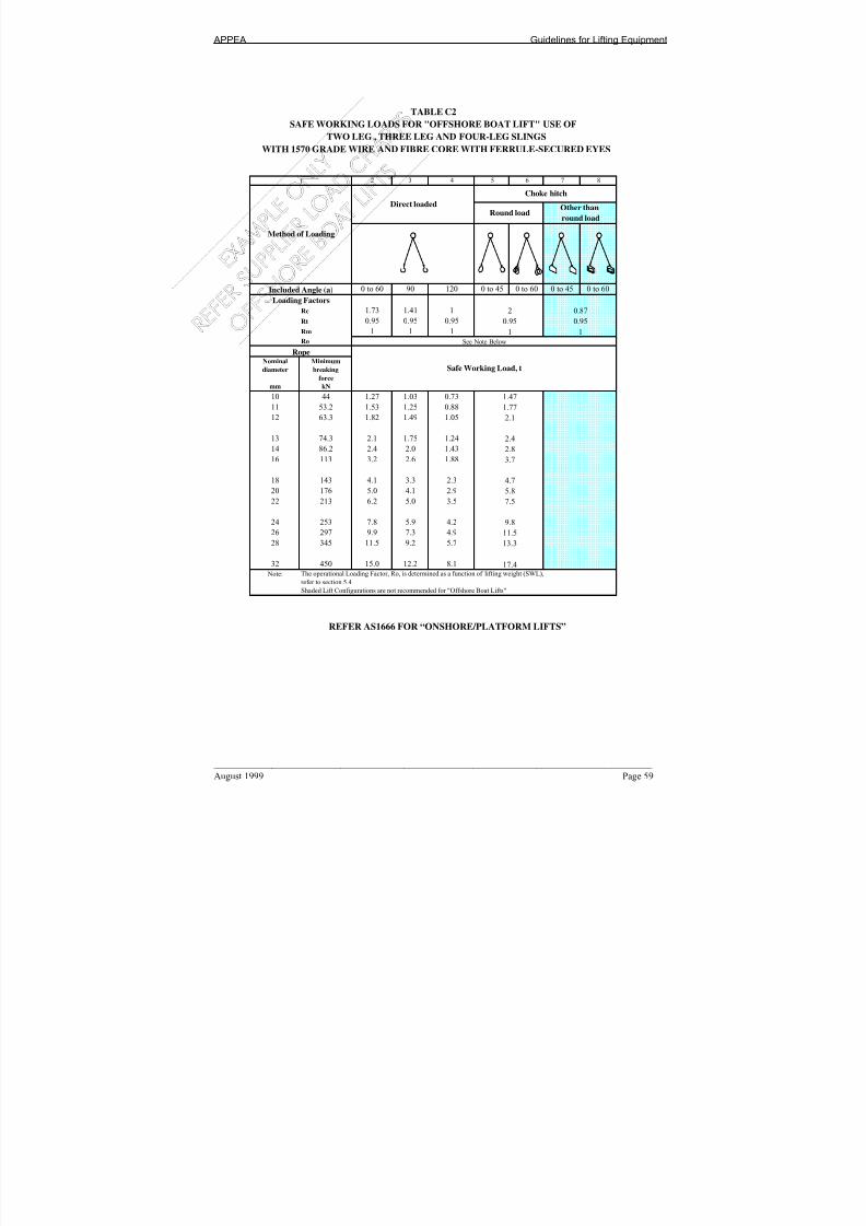
7/24/2019 APPEA Lifitng and Rigging Guidelines
http://slidepdf.com/reader/full/appea-lifitng-and-rigging-guidelines 61/109
APPEA Guidelines for Lifting Equipment
____________________________________________________________________________ August 1999 Page 59
REFER AS1666 FOR “ONSHORE/PLATFORM LIFTS”
2 3 4 5 6 7 8
0 to 60 90 120 0 to 45 0 to 60 0 to 45 0 to 60
Rc 1.73 1.41 1
Rt 0.95 0.95 0.95
Rm 1 1 1
Ro
Nominal Minimum
diameter breaking
force
mm kN
10 44 1.27 1.03 0.73
11 53.2 1.53 1.25 0.88
12 63.3 1.82 1.49 1.05
13 74.3 2.1 1.75 1.24
14 86.2 2.4 2.0 1.43
16 113 3.2 2.6 1.88
18 143 4.1 3.3 2.3
20 176 5.0 4.1 2.9
22 213 6.2 5.0 3.5
24 253 7.8 5.9 4.2
26 297 9.9 7.3 4.9
28 345 11.5 9.2 5.7
32 450 15.0 12.2 8.1
Note:
Shaded Lift Configurations are not recommended for "Offshore Boat Lifts"
The operational Loading Factor, Ro, is determined as a function of lifting weight (SWL),refer to section 5.4
17.4
11.5
13.3
7.5
9.8
4.7
5.8
2.8
3.7
2.1
2.4
Safe Working Load, t
1.47
1.77
Included Angle (a)
Loading Factors
2 0.87
0.95 0.95
1 1
See Note Below
Rope
Method of Loading
Direct loaded
Choke hitch
Round loadOther than
round load
1
TABLE C2
SAFE WORKING LOADS FOR "OFFSHORE BOAT LIFT" USE OF
TWO LEG , THREE LEG AND FOUR-LEG SLINGS
WITH 1570 GRADE WIRE AND FIBRE CORE WITH FERRULE-SECURED EYES

7/24/2019 APPEA Lifitng and Rigging Guidelines
http://slidepdf.com/reader/full/appea-lifitng-and-rigging-guidelines 62/109
APPEA Guidelines for Lifting Equipment
Page 60 August 1999
REFER AS1666 FOR “ONSHORE/PLATFORM LIFTS”
2 3 4 5 6 7 8 9 10 11 12
Direct
Loaded Round Rectangular
load load
- - - 0 60 90 120 0 60 90 120
Rc 1 0.75 0.5 2 1.73 1.41 1 1 0.87 0.71 0.5
Rt 0.95 0.95 0.95 0.95 0.95 0.95 0.95 0.95 0.95 0.95 0.95
Rm 1 1 1 1 1 1 1 1 1 1 1
Ro
Nominal Minimum
diameter breaking
force
mm kN
10 63.1 1.05 0.79 0.52
11 76.3 1.27 0.95 0.63
12 90.8 1.51 1.13 0.75
13 107 1.78 1.34 0.8914 124 2.0 1.55 1.03
16 161 2.6 2.0 1.34
18 204 3.4 2.5 1.70
20 252 4.2 3.1 2.10
22 305 5.0 3.8 2.5
24 363 6.0 4.5 3.0
26 426 7.5 5.3 3.5
28 494 9.4 6.2 4.1
32 646 12.5 9.1 5.3
36 817 15.8 11.8 7.1
40 1010 19.5 14.6 9.7
44 1220 23.6 17.7 11.8
48 1450 25.0 21.0 14.0
52 1710 - 24.8 16.5
56 1980 - 25.0 19.1
60 2270 - - 21.9
Note: The operational Loading Factor, Ro, is determined as a function of lifting weight (SWL), Refer Section 5.4
Shaded Lift Configurations are not recommended for "Offshore Boat Lifts"
Loading Factors
See Note Below
Rope
Safe Working Load, t
Basket Hitch
Round load Other than round load
Included An le (a)
TABLE C3
SAFE WORKING LOADS FOR TABLE "OFFSHORE BOAT LIFT" USE OF SINGLE-PART SINGLE-LEG SLINGS
WITH 1770 GRADE WIRE AND FIBRE-ROPE CORE WITH FERRULE-SECURED EYES
1
Method of Loading
Choke Hitch

7/24/2019 APPEA Lifitng and Rigging Guidelines
http://slidepdf.com/reader/full/appea-lifitng-and-rigging-guidelines 63/109
APPEA Guidelines for Lifting Equipment
____________________________________________________________________________ August 1999 Page 61
REFER AS1666 FOR “ONSHORE/PLATFORM LIFTS”
2 3 4 5 6 7 8
0 to 60 90 120 0 to 45 0 to 60 0 to 45 0 to 60
Rc 1.73 1.41 1Rt 0.95 0.95 0.95
Rm 1 1 1
Ro
Nominal Minimum
diameter breaking
force
mm kN
10 63.1 1.82 1.48 1.05
11 76.3 2.20 1.79 1.27
12 90.8 2.62 2.13 1.51
13 107 3.1 2.52 1.78
14 124 3.6 2.9 2.0716 161 4.7 3.8 2.68
18 204 5.9 4.8 3.4
20 252 7.8 5.9 4.2
22 305 10.2 7.7 5.1
24 363 12.1 9.9 6.1
26 426 14.2 11.6 7.5
28 494 16.5 13.4 9.5
32 646 21.6 17.6 12.5
36 817 25.0 22.3 15.8
40 1010 - 25.0 19.5
44 1220 - - 25.0
Note: The operational Loading Factor, Ro, is determined as a function of lifting weight (SWL),
refer to section 5.4
Shaded Lift Configurations are not recommended for "Offshore Boat Lifts"
-
-
-
19.1
25.0
14.0
16.5
9.7
11.8
5.4
7.1
3.6
4.1
2.54
3.0
See Note Below
Rope
Safe Working Load, t
2.10
0.95 0.95
1 1
Included Angle (a)
Loading Factors
2 0.87
WITH 1770 GRADE WIRE AND WIRE-ROPE CORE WITH FERRULE-SECURED EYES
1
Method of Loading
Direct loaded
Choke hitch
Round loadOther than
round load
TABLE C4
TWO LEG , THREE LEG AND FOUR-LEG SLINGS
SAFE WORKING LOADS FOR "OFFSHORE BOAT LIFT" USE OF

7/24/2019 APPEA Lifitng and Rigging Guidelines
http://slidepdf.com/reader/full/appea-lifitng-and-rigging-guidelines 64/109
APPEA Guidelines for Lifting Equipment
Page 62 August 1999
REFER AS1666 FOR “ONSHORE/PLATFORM LIFTS”
2 3 4 5 6 7 8 9 10 11 12
Direct
Loaded Round ectangular
load load
- - - 0 60 90 120 0 60 90 120
Rc 1 0.75 0.5 2 1.73 1.41 1 1 0.87 0.71 0.5
Rt 0.95 0.95 0.95 0.95 0.95 0.95 0.95 0.95 0.95 0.95 0.95
Rm 1 1 1 1 1 1 1 1 1 1 1
Ro
Nominal Minimum
diameter breaking
force
mm kN
10 58 0.96 0.72 0.48
11 70.1 1.17 0.87 0.58
12 83.5 1.39 1.04 0.69
13 98.4 1.64 1.23 0.82
14 114 1.9 1.42 0.95
16 148 2.4 1.8 1.23
18 187 3.1 2.3 1.56
20 231 3.8 2.8 1.90
22 280 4.6 3.5 2.3
24 333 5.5 4.1 2.7
26 391 6.7 4.8 3.2
28 454 8.2 5.6 3.7
32 594 11.5 8.0 4.9
36 751 14.5 10.9 6.3
40 929 17.9 13.4 8.5
44 1122 21.7 16.2 10.8
48 1334 25.0 19.3 12.9
52 1573 - 22.8 15.2
56 1821 - 25.0 17.6
60 2088 - - 20.2
Note: The operational Loading Factor, Ro, is determined as a function of lifting weight (SWL), Refer Section 5.4
Shaded Lift Configurations are not recommended for "Offshore Boat Lifts"
WITH 1770 GRADE WIRE AND FIBRE CORE WITH FERRULE-SECURED EYES
Included Angle (a)
Loading Factors
See Note Below
Ro e
Safe Working Load, t
Method of Loading
Choke Hitch Basket Hitch
Round load Other than round load
TABLE C5
SAFE WORKING LOADS FOR TABLE "OFFSHORE BOAT LIFT" USE OF SINGLE-PART SINGLE-LEG SLINGS
1

7/24/2019 APPEA Lifitng and Rigging Guidelines
http://slidepdf.com/reader/full/appea-lifitng-and-rigging-guidelines 65/109
APPEA Guidelines for Lifting Equipment
____________________________________________________________________________ August 1999 Page 63
REFER AS1666 FOR “ONSHORE/PLATFORM LIFTS”
2 3 4 5 6 7 8
0 to 60 90 120 0 to 45 0 to 60 0 to 45 0 to 60
Rc 1.73 1.41 1
Rt 0.95 0.95 0.95
Rm 1 1 1
Ro
Nominal Minimum
diameter breaking
force
mm kN
10 58 1.67 1.36 0.96
11 70.1 2.02 1.65 1.17
12 83.5 2.41 1.96 1.39
13 98.4 2.8 2.31 1.64
14 114 3.3 2.7 1.90
16 148 4.3 3.5 2.47
18 187 5.4 4.4 3.1
20 231 6.9 5.4 3.9
22 280 9.2 6.8 4.7
24 333 11.1 8.7 5.6
26 391 13.1 10.6 6.7
28 454 15.2 12.3 8.3
32 594 19.9 16.2 11.536 751 25.0 20.5 14.5
40 929 - 25.0 17.9
44 1122 - - 21.7
Note:
refer to section 5.4
SAFE WORKING LOADS FOR "OFFSHORE BOAT LIFT" USE OF
The operational Loading Factor, Ro, is determined as a function of lifting weight (SWL),
refer to section 5.4
25.0
25.0
-
17.5
23.0
12.8
15.1
8.5
10.8
4.9
6.3
3.3
3.8
2.34
2.8
See Note Below
Rope
Safe Working Load, t
1.93
0.95 0.95
1 1
Included An le (a)
Loading Factors
2 0.87
1
Method of Loading
Direct loaded
Choke hitch
Round loadOther than
round load
TABLE C6
TWO LEG , THREE LEG AND FOUR-LEG SLINGS
WITH 1770 GRADE WIRE AND FIBRE CORE WITH FERRULE-SECURED EYES
The operational Loading Factor, Ro, is determined as a function of lifting weight (SWL),
Refer Section 5.4Shaded Lift Configurations are not recommended for “Offshore Boat Lifts”

7/24/2019 APPEA Lifitng and Rigging Guidelines
http://slidepdf.com/reader/full/appea-lifitng-and-rigging-guidelines 66/109
APPEA Guidelines for Lifting Equipment
Page 64 August 1999
REFER AS3776 FOR “ONSHORE/PLATFORM LIFTS”
1 2 3 4 5 6 7 8 9 10 11 12 13 14 15 16 17
Stra ight Adjustable Reeved
Sling Sling Sling
- - - 60 90 120 60 90 120 60 90 120 -
Rc 1 0.75 0.75 1.73 1.41 1 1.30 1.06 0.75 1.30 1.06 0.75 1.5
Rt 1 1 1 1 1 1 1 1 1 1 1 1 1
Rm 1 1 1 1 1 1 1 1 1 1 1 1 1
Ro
Minimum
Non- breaking
preferred force
(mm) (mm) (in) k N
10 126.0 2.21 3.8 3.1 2.21
11 158 2.77 4.8 3.9 2.7
12 197 3.46 5.9 4.8 3.4
1/2 203 3.57 6.2 5.0 3.5
13 213 3.7 6.6 5.2 3.7
14 248 4.3 8.2 6.1 4.3
5/8 317 5.5 11.4 8.7 5.5
16 322 5.6 11.6 8.9 5.6
18 408 7.6 15.2 12.0 7.6
3/4 457 9.0 17.3 13.7 9.0
20 503 10.4 19.4 15.2 10.4
22 621 13.1 25.0 19.5 13.1
24 631 13.3 - 19.9 13.3
25 724 15.6 - 23.6 15.6
1 786 17.2 - 25.0 17.2
27 811 17.8 - - 17.8
28 917 20.7 - - 20.7
30 986 22.6 - - 22.6
1 1/4 1267 25.0 - - 25.0
No te: The ope rational Loading Factor, Ro, is de termined as a function of lifting weight (SWL), Refer Section 5.4Sling Types in shaded region are not recommended for Offshore Lifts
SAFE WORKING LOADS FOR "OFFSHORE BOAT LIFT" USE OF SLINGS
TABLE C7
Method of Loading
Single Leg Slings Slings of 2,3 or 4 legs Endless Slings
Straight Sling Reeved Sling Basket/Reeved Sling
Included Angle (a)
Loading Factors
See Note Below
Chain
Safe Working Load, tSize (as designated by AS232 1)
Preferred Temporary
WITH GRADE T CHAIN

7/24/2019 APPEA Lifitng and Rigging Guidelines
http://slidepdf.com/reader/full/appea-lifitng-and-rigging-guidelines 67/109
APPEA Guidelines for Lifting Equipment
____________________________________________________________________________ August 1999 Page 65
APPENDIX D
DYNAMIC AMPLIFICATION FACTOR

7/24/2019 APPEA Lifitng and Rigging Guidelines
http://slidepdf.com/reader/full/appea-lifitng-and-rigging-guidelines 68/109
APPEA Guidelines for Lifting Equipment
Page 66 August 1999
FIGURE D.1 RECOMMENDED DYNAMIC AMPLIFICATION FACTOR(DAF)
0
0.4
0.8
1.2
1.6
2
2.4
2.8
3.2
0 5 10 15 20 25
Lifted Mass (tonnes)
D y n a m i c A m p l i f i c a t i o n F a c t o r ( D A F )

7/24/2019 APPEA Lifitng and Rigging Guidelines
http://slidepdf.com/reader/full/appea-lifitng-and-rigging-guidelines 69/109
APPEA Guidelines for Lifting Equipment
____________________________________________________________________________ August 1999 Page 67
APPENDIX E
CONTAINER MARKING EXAMPLE

7/24/2019 APPEA Lifitng and Rigging Guidelines
http://slidepdf.com/reader/full/appea-lifitng-and-rigging-guidelines 70/109
APPEA Guidelines for Lifting Equipment
Page 68 August 1999
FIGURE E.1 INSPECTION DATA PLATE
215
35 180 (6 x 30)
INSPECTION DATA – OFFSHORE CONTAINER
Container No.
Maximum Gross Mass kg @ deg. Sling angle
Tare Mass kg
Payload Container kg
Intermediate deck kg
Owner:
Tel. No. +
+
+
TEST PROOF LOAD NDT VISUAL
INSPECTION
INTERVAL 6 YEAR TEST 3 YEAR TEST 1 YEAR TEST
DATE CERT NO DATE CERT NO DATE CERT NOAT
MANUFACTURE
AT
SITE
1.5 mm STAINLESS STEEL 5 mm LETTERING
Suggested plate incorporates ideas from international documents and local
requirements. All dimensions are shown in mm.
250 mm
70 mm
10 mm LETTERING

7/24/2019 APPEA Lifitng and Rigging Guidelines
http://slidepdf.com/reader/full/appea-lifitng-and-rigging-guidelines 71/109
APPEA Guidelines for Lifting Equipment
____________________________________________________________________________ August 1999 Page 69
FIGURE E.2 IDENTIFICATION PLATE
215 mm
OFFSHORE CONTAINER
Name of Manufacturer
Month/year of Manufacture
Manufacturer’s serial No.
Maximum Gross Mass kg @ deg. Sling angle
Tare Mass kgPayload Container kg
Intermediate deck kg
Certificate of Conformity No.
Design Temperature oC
The suggested plate is in line with international document requirements.
1.5 mm STAINLESS STEEEL
150 mm
10 mm LETTERING5 mm LETTERING

7/24/2019 APPEA Lifitng and Rigging Guidelines
http://slidepdf.com/reader/full/appea-lifitng-and-rigging-guidelines 72/109
APPEA Guidelines for Lifting Equipment
Page 70 August 1999
FIGURE E.3 OPERATIONAL MARKING PLATE
ID No TW-SS01
OWNER WOODSIDE
MANUFACTURER DISON
DATE OF
MANUFACTURE
12/96
TYPE OFFSHORE EQUIPMENT CONTAINER
All dimensions shown are in mm.
200
2mm Stainless steel plate
90
6.4 TY

7/24/2019 APPEA Lifitng and Rigging Guidelines
http://slidepdf.com/reader/full/appea-lifitng-and-rigging-guidelines 73/109
APPEA Guidelines for Lifting Equipment
____________________________________________________________________________ August 1999 Page 71
FIGURE E.4 IDENTIFICATION NUMBER
Needs to be 75mm minimum lettering to comply with
international document requirements ⁄ ⁄⁄ ⁄
PW - SS01
All dimensions shown are in mm.
VARIES
6.3 70 6.2 50

7/24/2019 APPEA Lifitng and Rigging Guidelines
http://slidepdf.com/reader/full/appea-lifitng-and-rigging-guidelines 74/109
APPEA Guidelines for Lifting Equipment
Page 72 August 1999
7/24/2019 APPEA Lifitng and Rigging Guidelines
http://slidepdf.com/reader/full/appea-lifitng-and-rigging-guidelines 75/109
APPEA Guidelines for Lifting Equipment
____________________________________________________________________________ August 1999 Page 73
APPENDIX F
INSPECTION & TESTING REQUIREMENTS

7/24/2019 APPEA Lifitng and Rigging Guidelines
http://slidepdf.com/reader/full/appea-lifitng-and-rigging-guidelines 76/109
APPEA Guidelines for Lifting Equipment
Page 74 August 1999
TABLE F.1
INSPECTION AND TESTING REQUIREMENTS FOR LIFTING DEVI
P
ITEM
REFERENCE
CERTIFIED
VISUAL
INSPECTION
NDT FREQU
Cranes
(The various types of cranes and
lifting appliances are listed in
AS 1418)
Onshore/Inshore:
• AS 1418 (Parts 1 to 17)
• AS 2550
• MO 32
• State Acts & Regulations
• Manufacturer’s Specs
Offshore:• API Spec 2C
• BS 2573
• Lloyds Code for Lifting
Appliances in a Marine
Environment
• Manufacturer’s Specs
1 Year
Subject to:
• Visual inspection
• Failure Mode
Analysis
• Individual
Company Program
• Initial Certifica
• Following Repa
Subject to:
• Visual inspectio
• NDT
• Individual Com
MO32 specifies eve
Individual State Reg
every 12 months for
Overhead Padeyes AS1418.1 & .2
MO 32
1 Years *
Subject to visual
inspection or every 3
years
Initial test and then
inspection, NDT and
company program.
Forklift tynes AS 2359 1 Year
Subject to visual
inspection
Initial test and then
inspection, NDT andcompany program.
Mono rails P(SL)A AS1418.1 & .2 1 Years * Initial NDT, then
subject to visual
inspection
Subject to individua
program
Note: * Certified Visual Inspection includes permanent marking of SWL
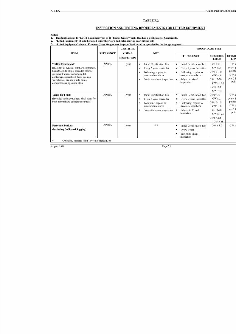
7/24/2019 APPEA Lifitng and Rigging Guidelines
http://slidepdf.com/reader/full/appea-lifitng-and-rigging-guidelines 77/109
APPEA
August 1999 Page 75
TABLE F.2
INSPECTION AND TESTING REQUIREMENTS FOR LIFTED EQUIPM
Notes:
1.
This table applies to “Lifted Equipment” up to 25
*
tonnes Gross Weight that has a Certificate of Conformity.2.
“Lifted Equipment” should be tested using their own dedicated rigging gear (lifting set).
3. “Lifted Equipment” above 25* tonnes Gross Weight may be proof load tested as specified by the design engineer.
P
ITEM
REFERENCE
CERTIFIED
VISUAL
INSPECTION
NDT FREQUENC
“Lifted Equipment”
(Includes all types of offshore containers,
baskets, skids, skips, spreader beams,
spreader frames, workshops, lab
containers, specialised items such aswork boxes, drilling guide bases,
conductor casing joints, etc.)
APPEA 1 year
• Initial Certification Test
• Every 3 years thereafter
• Following repairs to
structural members
• Subject to visual inspection
• Initial Certifica
• Every 6 years th
• Following repa
structural memb
• Subject to visua
inspection
Tanks for Fluids
(Includes tanks/containers of all sizes for
both normal and dangerous cargoes)
APPEA 1 year
• Initial Certification Test
• Every 3 years thereafter
• Following repairs to
structural members
• Subject to visual inspection
• Initial Certifica
• Every 6 years th
• Following repa
structural memb
• Subject to VisuInspection
Personnel Baskets
(Including Dedicated Rigging)
APPEA 1 year
N/A • Initial Certifica
• Every 1 year
• Subject to visua
inspection
* Arbitrarily selected limit for “Engineered Lifts”

7/24/2019 APPEA Lifitng and Rigging Guidelines
http://slidepdf.com/reader/full/appea-lifitng-and-rigging-guidelines 78/109
APPEA Guidelines for Lifting Equipment
Page 76 August 1999
TABLE F.3
INSPECTION AND TESTING REQUIREMENTS FOR RIGGING
Notes:1.
Offshore containers shall have specifically designed lifting sets, which shall not be removed from the container except for re
of the container.
2.
For Safety Factors for Rigging Equipment used in Offshore Lifting Operations refer to section 5.4.
3.
Minimum chain diameter to be 10mm. For containers with Gross Weight more than 3500kg, the minimum chain diameter m
4. Min. Wire Rope diameter to be 13mm. For containers with Gross Weight more than 3500kg, the minimum wire rope diame
PRO
ITEM
REFERENCE
CERTIFIED
VISUAL
INSPECTION
NDT FREQUENCY
Loose Rigging
(Includes all types wire and synthetic ropes, chains, links,
shackles, swivels, rings, sockets,
hammerlocks, etc)
APPEA • Not Required
• 3 monthly visualinspections
• Colour coding
• Visual inspectioneach time before use.
Subject to visual
inspection
• Initial Certification Test
• Subject to company program.
Lifting Sets
(Includes wire rope and chain
sets, complete with all
associated accessories)
APPEA 1 year
as part of the container
inspection.
Subject to visualinspection.
• Initial Certification Test
• Offshore – Every 6
years as part of the
“Lifted Equipment”
Proof Load Test.
Crane Hooks APPEA 1 year
• Every 2 years
• Subject to Visual
Inspection
• Initial Certification Test

7/24/2019 APPEA Lifitng and Rigging Guidelines
http://slidepdf.com/reader/full/appea-lifitng-and-rigging-guidelines 79/109
APPEA Guidelines for Lifting Equipment
August 1999 Page 77
APPENDIX G
GUIDE TO AUSTRALIAN AND INTERNATIONAL STANDARDS

7/24/2019 APPEA Lifitng and Rigging Guidelines
http://slidepdf.com/reader/full/appea-lifitng-and-rigging-guidelines 80/109
APPEA Guidelines for Lifting Equipment
Page 78 August 1999
Table G1- Guide to Australian and International Standards
Note: This table is intended as a guide only. In many cases, requirements of International standards will be less onerous than Austr
than Australian standards are not recommended to be adopted without specific Operator approval.
Aust/NZ No Australian/New Zealand Title ANSI Standard British Standard
AS ISO-1000 The International System of Units - BS 5555 -
AS 1138 Thimbles for Wire Rope - BS 464
BS 3226
Rules f
Part 2 C
AS 1171 Non-Destructive Testing Magnetic
Particle Testing of Ferromagnetic
Products, Components and Structures
- BS 6072 -
AS 1353 Flat Synthetic Webbing Slings - BS 3481
BS 5053
-
AS 1380 Fibre Rope Slings - BS 2052
BS 4921
BS 7648
-
AS 1418 Cranes (Including Hoists & Winches) ASME B30API RP2D
Spec 2C
BS 327BS 357
BS 466
BS 1757
BS 2452
BS 2573
BS 2799BS MA41
BS MA79
Rules fLifting
AS 1438 Wire - Coil Flat Slings - - -
AS 1504 Fibre Rope - Three Strand Hawser
Laid
- - -
AS/NZS 1554 Structural Steel Welding AWS D1.1 BS 4870 -
AS 1657 Fixed Platforms, Walkways,
Stairways and Ladders - Design,
Construction and Installation
A1264.1 BS 4592
BS 5395
-
AS 1664 Aluminium Structures Code AWS D1.2 BS 8118 -

7/24/2019 APPEA Lifitng and Rigging Guidelines
http://slidepdf.com/reader/full/appea-lifitng-and-rigging-guidelines 81/109
APPEA
August 1999 Page 79
Aust/NZ No Australian/New Zealand Title ANSI Standard British Standard
BS CP118
AS 1666 Wire Rope Slings ASME B30.9 BS 1290 Rules f
Part 2 CAS 2089 Sheave Blocks of Maximum Lift 60
Tonne
- BS 4018
BS 4344
BS 4536
BS MA47
Rules f
Part 2 C
AS 2207 Non-Destructive Testing for
Ultrasonic Testing of Fusion Welded
Joints in Carbon & Low Alloy Steel
AWS C3.8 BS EN 1714 -
AS 2317 Collared Eyebolts ASME B18.15 BS 4278 -
AS 2318 Swivels for Hoists - - Rules f
Part 2 C
AS 2319 Rigging Screws and Turnbuckles - BS 4429 -
AS 2321 Short Link Chain for LiftingPurposes (Non Calibrated) ASME B29 BS 3113BS 3458
BSEN 818-1
BS 6304
Rules fPart 2 C
AS 2550 (1982) Cranes – Safe Use ASME B30 - Rules fLifting
AS 2741 Shackles - BS 3551
BS 6994
Rules f
Part 2 C
AS 2759 Steel Wire Rope - Application Guide API RP9B BS 6210
BS 6570
-
AS 3569 Steel Wire Ropes Spec 9A BS 183
BS 302
BS 525
Rules f
Part 2 C
AS/NZS 3678 Structural Steel – Hot Rolled Plates,Floor Plates and Slabs
SAE J763SAE J1392
BS 7613 -
AS/NZS 3679.1 Structural Steel – Part 1 : Hot Rolled
Bars and Sections
SAE J1442 BSEN 10210-2 -
AS/NZS 3679.2 Structural Steel – Part 2 : Welded I
Sections
- - -

7/24/2019 APPEA Lifitng and Rigging Guidelines
http://slidepdf.com/reader/full/appea-lifitng-and-rigging-guidelines 82/109
APPEA Guidelines for Lifting Equipment
Page 80 August 1999
Aust/NZ No Australian/New Zealand Title ANSI Standard British Standard
AS 3775 Chain Slings – Grade T ASME B29 BS 2902
BS 6968
Rules f
Part 2 C
AS 3776 Lifting Components for Grade TChain Slings
- - Rules fPart 2 C
AS 3777 Shank Hooks and Large Eye Hooks -
Maximum 25 Tonne
ASME B30.10 BS 2903 Rules f
Part 2 C
AS 3990 Mechanical Equipment - Steelwork AISC BS 5950
BS 7608
DDENV 1993
DDENV 1994
-
AS 4048 Flat Pallets for Materials Handling
(1100mm x 1100mm suitable for use
in ISO Series 1 Freight Containers)
ASME MH BS 3810
BS 6637
BS M69
-
AS 4100 Steel Structures AISC BS 5950
BS 7608
DDENV 1993DDENV 1994
-
AS 4142 Fibre Rope - BSEN 698
BSEN 701
BSEN 1251
BS 7648
Rules f
Part 2 C
AS B291 Lifting Rings & Links - - Rules f
Part 2 C
AS/NZS 3711.1 Freight Containers:- Part 1
Classification, Dimensions & Ratings
ANSI MH BS 3951 -
AS/NZS 3711.2 Freight Containers:- Part 2 –
Terminology
ANSI MH BS 3951 -
AS/NZS 3711.3 Freight Containers:- Part 3 - Corner
Fittings
ANSI MH BS 3951 -
AS/NZS 3711.4 General Purpose Containers ANSI MH BS 3951 -
AS/NZS 3711.5 Thermal Containers ANSI MH BS 3951 -
AS/NZS 3711.6 Tank Containers ANSI MH BS 3951 -

7/24/2019 APPEA Lifitng and Rigging Guidelines
http://slidepdf.com/reader/full/appea-lifitng-and-rigging-guidelines 83/109
APPEA
August 1999 Page 81
Aust/NZ No Australian/New Zealand Title ANSI Standard British Standard
AS/NZS 3711.7 Dry Bulk Containers ANSI MH BS 3951 -
AS/NZS 3711.8 Platform Containers ANSI MH BS 3951 -
AS/NZS 3711.9 Coding, Identification and Marking ANSI MH BS 3951 -
AS/NZS 3711.10 Handling and Securing ANSI MH BS 3951 -

7/24/2019 APPEA Lifitng and Rigging Guidelines
http://slidepdf.com/reader/full/appea-lifitng-and-rigging-guidelines 84/109
APPEA Guidelines for Lifting Equipment
Page 82 August 1999

7/24/2019 APPEA Lifitng and Rigging Guidelines
http://slidepdf.com/reader/full/appea-lifitng-and-rigging-guidelines 85/109
APPEA Guidelines for Lifting Equipment - Phase Out of ISO Containers
August 1999 Page 83
APPENDIX H
GUIDELINES FOR THE PHASEOUT OF ISO SHIPPING
CONTAINERS OFFSHORE

7/24/2019 APPEA Lifitng and Rigging Guidelines
http://slidepdf.com/reader/full/appea-lifitng-and-rigging-guidelines 86/109

7/24/2019 APPEA Lifitng and Rigging Guidelines
http://slidepdf.com/reader/full/appea-lifitng-and-rigging-guidelines 87/109
APPEA Guidelines for Lifting Equipment - Phase Out of ISO Containers
August 1999 Page 85
PREAMBLE
The purpose of this document is to provide a guideline for the inspection and testing of ISO shipping
containers used in the offshore oil & gas industry. ISO shipping containers are not designed for use in
the offshore industry where dynamic lifting forces apply.
These guidelines will remain in force until the target phase out date of 31/12/2000 is reached. Whilstthis is an industry target date, individual companies may require that ISO containers be removed from
service at an earlier date. In the interim this document will provide guidance for the management of
ISO containers including inspection, de-rating and testing requirements.
For design and fabrication of replacement containers the requirements of the draft APPEA “Guideline
for Lifting Equipment” should be used. The following section is extracted from the referenced document.
7/24/2019 APPEA Lifitng and Rigging Guidelines
http://slidepdf.com/reader/full/appea-lifitng-and-rigging-guidelines 88/109
APPEA Guidelines for Lifting Equipment - Phase Out of ISO Containers
Page 86 August 1999
DOCUMENT SCOPE
Provision of procedures & guidelines to manage the use of ISO containers
used in the offshore industry.
The document provides guidelines for the inspection, testing and marking of ISO containers used in the transport of goods to and from offshore locations.
The use of the containers is to be managed in accordance with this document.
DOCUMENT SOURCE
& RECOGNITION Much of the information contained within the documents on ISO Containers
has been reproduced from Woodside Energy Ltd’s (WEL), King Bay Supply
Base, Lifting Equipment Management System.APPEA thank WEL for their contribution in permitting contents of their
documents to be reproduced herein.
IDENTIFICATION OF
“ISO” CONTAINERS ISO containers are the containers originally built for international shipping and fitted with ISO Corner fittings and lifted in container ports, from these fittings,
with a purpose built spreader frame and special “Twist-locks”.
Most are 20ft in length although 10, 30 & 40ft lengths are also available.
NOTE: It is possible for purpose built offshore containers to have ISO Corner
fittings.
This is quite acceptable, provided that these are only used for securing during
transport and/or onshore/inshore lifting in accordance with onshore/inshore
container lifting guidelines as detailed in AS 3711.10:1993 “Freight
Containers – Handling and Securing” and, are not used for offshore lifting.
CONTROLLED USE OF
ISO CONTAINERS
Containers used in international shipping are controlled by the International
Convention for Safe Containers (CSC).When the containers used in international and/or coastal shipping reach the
end of their service life, either through condition or a “time life” expiry they
are often sold off without current CSC compliance.
Any existing CSC compliance plate has no meaning in the offshore industry
except for a reference in de-rating the container as detailed within this
document.
The containers are designed and rated for use in still water ports and not for
offshore use where significant dynamic forces occur during lifting operations.
REFERENCE
MATERIAL
Marine Orders, Part 44, Section 11
International Maritime Organization Circular 613 (to be replaced by Maritime
Safety Committee, Circular 860)
International Convention for Safe Containers (CSC) IMO, 1982
DNV 2.7-1 Offshore Containers -Certification Notes.
AS3711.10 – 1993 - Freight Containers, Handling & Securing
APPEA “Guideline For Lifting Equipment.”
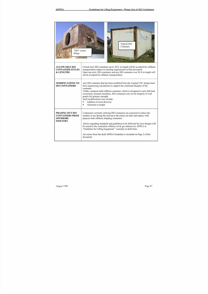
7/24/2019 APPEA Lifitng and Rigging Guidelines
http://slidepdf.com/reader/full/appea-lifitng-and-rigging-guidelines 89/109
APPEA Guidelines for Lifting Equipment - Phase Out of ISO Containers
August 1999 Page 87
ALLOWABLE ISO
CONTAINER STYLES& LENGTHS
Closed roof, ISO containers up to 20 ft. in length will be accepted for offshore
transportation subject to meeting requirements of this document.Open top style, ISO containers and any ISO container over 20 ft in length will
not be accepted for offshore transportation.
MODIFICATIONS TO
ISO CONTAINERS
Any ISO container that has been modified from the original CSC design must
have engineering calculations to support the continued integrity of thecontainer.
Unlike a purpose built offshore container, which is designed to carry full load
on primary structure members, ISO containers rely on the integrity of wall
panels for primary strength.
Such modifications may include:
• Addition of extra doorway
• Alteration to length
PHASING OUT ISO
CONTAINERS FROM
OFFSHORE
INDUSTRY
Contractors currently utilizing ISO containers are expected to reduce the
number in use during the lead up to the phase out date and replace with
purpose built offshore shipping containers.
Advice regarding standards and guidelines to be followed for new designs will
be issued to the Australian offshore oil & gas industry by APPEA in
“Guideline for Lifting Equipment ” currently in draft form.
An extract from the draft APPEA Guideline is included on Page 2 of this
document.
“ISO” corner
fitting
Typical ISO
Container

7/24/2019 APPEA Lifitng and Rigging Guidelines
http://slidepdf.com/reader/full/appea-lifitng-and-rigging-guidelines 90/109
APPEA Guidelines for Lifting Equipment - Phase Out of ISO Containers
Page 88 August 1999
COMMENTARY ON
LIFTING POINTS• Even in a still water port situation, ISO shipping containers cannot be
lifted from the ISO Corner fittings by shackles and slings. This applies
even when empty.
• Lifting with spreader frames as used in port situations is not allowed inoffshore lifting operations. Refer to clause 2.2 of IMO 613 (referred to in
Marine Orders Part 44.)
NOTE: IMO 613 will be replaced by a new Maritime Safety Committee
document “Guidelines for the Approval of Offshore Containers Handled in
Open Seas.” (MSC Circular 860) This document further emphasises that ISO
corner fittings are not to be used for lifting in offshore transport operations.
ISO containers used in the offshore industry should have padeyes that are
purpose built. Refer to “Padeyes” below.
PADEYE
REQUIREMENTS
The installation of padeyes must be carried out in accordance with good engineering practices.
• Design by qualified structural engineer.
• Design verification by independent engineer, who has not been involved
in the design.
• Carry MGW on 2 of four padeyes.
• Align to centre of gravity of the load to provide for the angle of the lifting
forces to be 45 degrees from the vertical.
• Shackle pin hole to be +3mm or, not greater than 4% more than the
shackle pin diameter.
• Width of padeye to be equal to 75% of the opening of shackle to be fitted.
This may be accomplished by fitting bosses to padeye.
• Material trace-ability.
• Documented welding procedures (To AS1554, AWSD1.1 etc.)
• Welder qualification trace-ability.
• NDT inspection of all welding associated with padeyes.
NOTES:
1. The installation of padeyes MUST have engineering trace-ability.2. DNV 2.7-1 provides full details of padeye design and material
requirements and designers are encouraged to use the DNV document as a
guide.
Shackles in ISOCorner fittings are not
permitted.
➚ Although not generally required whencontainer is down-rated, lifting with speciallifting beams will be allowed during phase out.
Must be fitted to padeyes as shown.

7/24/2019 APPEA Lifitng and Rigging Guidelines
http://slidepdf.com/reader/full/appea-lifitng-and-rigging-guidelines 91/109
APPEA Guidelines for Lifting Equipment - Phase Out of ISO Containers
August 1999 Page 89
ALLOWABLE MGW
(Maximum Gross
Weight)
ISO Containers used in the offshore industry where significant dynamic forces
occur during lifting from supply vessels must be significantly de-rated.
Subject to satisfactory inspections as per Page 7, ISO container use, up to the phase out date, will be allowed under the following conditions:
• De-rated by multiplying original CSC Maximum Gross Weight (or Mass)
x 2 and dividing the figure by 5.
E.g. A 24 tonne MGW container x times 2 = 48 tonnes divided by 5 = 9.6
tonnes MGW.
MARKING
REQUIREMENTS
All ISO containers, original or modified, shall have:
• A stenciled marking beside the CSC data plates indicating “NotApplicable”. The plate should remain to indicate the original MGW that is
used in the de-rating formula above.
Marking plates are required for:
• Operational Marking Plate (Tare, Nett & Gross)
• Test Plate (date of test and inspections) NOTE: Refer to pages 9 & 10 for details of plates.“Other” marking requirements
• Each container should be marked with a unique identification number
issued by the owner.
Notes:
1. The above number should be cross-referenced on all relevantdocumentation.
2. The number should be prominently displayed on a minimum of 2 sides of
the container in contrasting colours with stenciled characters of not less
than 75 mm in height.
FORKLIFT POCKETS ISO Containers often have more than 1 set of forklift pockets. Extreme caution
should be used when lifting a laden ISO container from the forklift pockets.
If there are two sets, with one set being close to the centre of the container, the
inner set are designed for “Empty lifting only”. These words must be stenciled
on the base frame adjacent to forklift pockets when such forklift pockets are
installed. Stenciling to be 75mm in height.There are instances where ISO containers have been modified and appear to
have useable forklift pockets on more than two sides, this can be a dangerous
situation as forklift pockets have been found that have the fork tynes bearing
on a plywood floor. Check before using and at scheduled inspection.
SLINGS Sling sets may be chain or wire rope.• Four sling assemblies are preferred
• Minimum sling angle of 60 degrees to horizontal.
• Chain used in stingers (or 5th
leg) must meet ISO 3076, or ISO 7593
standards.
Note: The use of stingers is discouraged as the redundancy in a 4 leg assemblyis lost.
SHACKLES Shackles must be:
• Grade “S” minimum
Safety pin type with split pin fitted

7/24/2019 APPEA Lifitng and Rigging Guidelines
http://slidepdf.com/reader/full/appea-lifitng-and-rigging-guidelines 92/109
APPEA Guidelines for Lifting Equipment - Phase Out of ISO Containers
Page 90 August 1999
CONTAINER
INSPECTIONS
ISO containers must receive a Thorough Visual Inspection both annually and
prior to any load testing.
• NDT Inspection of padeyes and floor support structure is to be carried out
annually and prior to load testing.
• All Thorough Visual Inspections and NDT must be recorded in a liftingequipment database.
THOROUGH VISUAL
& NDT INSPECTIONS
ANNUAL
REQUIREMENT
• Door latching mechanisms in good working order (where applicable)
• Container is free from obvious defects, corrosion, impact damage, cracks,
etc.
• Under-floor support structure inspection. The floor support structure is
very light in an ISO container and is prone to extensive corrosion and
cracking when used in the offshore environment.
• Place container on supports to allow full inspection of underside and
ensure adequate lighting.
• Look for corrosion and/or any cracking.• It may be necessary to sand blast corroded steel to allow full inspection.
• Suspected areas of cracking to have NDT inspections carried out.
• Steelwork that has suffered significant (greater than 10%) metal loss
through corrosion is to be replaced.
• Complete structure to be examined for corrosion, cracking, and impact
damage. Particular attention is to be given to inspection of lifting points
and corner post assemblies.
• Visually inspect all welds for defects.
• NDT all welds in padeye area. (NATA accredited NDT contractor
required)
• Inspect for signs of mechanical damage.
• Doors, frames, seals, hinges, locks should be examined and functionally
checked to ensure satisfactory operation without undue force.• Check floor is substantially flat with no signs of damage or other
indications that may indicate overloading. Any internal floor damage may
indicate underside damage- re-check.
• Marking Plates should be as per requirements of this document (pages 9
& 10).
7/24/2019 APPEA Lifitng and Rigging Guidelines
http://slidepdf.com/reader/full/appea-lifitng-and-rigging-guidelines 93/109
APPEA Guidelines for Lifting Equipment - Phase Out of ISO Containers
August 1999 Page 91
VISUAL INSPECTORS
KNOWLEDGE
REQUIREMENTS
The visual inspector should have, as a minimum, a knowledge and adequate
practical experience of:
• The statutory requirements relating to containers.
• The provisions of DNV 2.7-1 (to be used as a guide only as ISO
containers do not comply with offshore container standards).• The various types of containers in service.
• The correct methods of slinging and handling the containers.
• The loads affecting containers when handled under adverse offshore
conditions, particularly those affecting lifting points and, in the case of
ISO containers used offshore, the floor support structure.
• The methods of testing containers as detailed in Maritime Safety.
Committee circular 860 or, DNV2.7-1 Offshore Container, Certification
Notes.
• Defects likely to be found in containers and acceptable levels of wear,
distortion and deterioration in relation to safety in use.
• Welding methods and procedures and qualification of welders.
•
The various methods of non-destructive testing (NDT) and a good understanding of how they work and their limitations
• Procedures for measuring container to ensure distortion has not occurred
during service or load testing.
TESTING AN ISO
CONTAINER
As all ISO containers will be phased from the Australian offshore oil & gasout by 30/12/99 it is proposed that any containers currently in use undergo the
following load test (subject to satisfying inspection requirements) which
would see them through to phase out date.
• Testing of container as per “Testing Requirements” as detailed in IMO
613 & MSC 860. (Drop test will not be required)
TESTING
PROCEDURES
Prior to load testing, carry out Thorough Visual Inspection as detailed withinthis document.
(There is no value in testing a container that has defects)4 Point Lifting Test:
Internal Load (not to be hung under container): a uniformly distributed load,
such that the combined tare of the container and test load is equal to 2.5 timesthe de-rated MGM.
The container should be lifted with its lifting set attached to all four padeyes.
2 Point Lifting Test:
Internal load (not to be hung under container): a uniformly distributed load
such that the combined tare of the container and test load is equal to 1.5 times
the de-rated MGM. It may be necessary to secure the weights to prevent
slippage during testingThe container should be lifted with slings attached to two diagonally opposite
padeyes during the test.
Drop Test:
IMO 613 and DNV 2.7-1 require that containers be drop tested when
approving type designs. APPEA does not require that ISO design containers bedrop tested but the requirement will need to be met when type testing future
new container designs.

7/24/2019 APPEA Lifitng and Rigging Guidelines
http://slidepdf.com/reader/full/appea-lifitng-and-rigging-guidelines 94/109
APPEA Guidelines for Lifting Equipment - Phase Out of ISO Containers
Page 92 August 1999
ALLOWABLE
DEFLECTIONDURING &
SUBSEQUENT TO
LOAD TESTING
Allowable deflection limits are detailed within DNV 2.7-1 Certification notes – Offshore Containers.Refer to sections 3.7.1.2 & 3.7.1.3 of referenced DNV document.
COMMENTS ON
DEFLECTION
LIMITS
Where deflection exceeds the maximum allowable limit, the container should
be scrapped.
Offshore Container Identification Plate
OFFSHORE CONTAINER
Name of Manufacturer (if known) Month/year of Manufacture (if known)
Manufacturers Serial No. (if known)
Maximum Gross Weight Kg at deg sling angle
Tare Weight Kg
Payload Container Kg
IDENTIFICATION
PLATE MATERIAL &
SIZE
REQUIREMENTS
• Plates to be of stainless steel, 1 .5 mm thick
• Affixed with stainless steel rivets (not aluminium)• 215 mm overall width
• 150 mm overall height
• Main heading alpha characters to be stamped 10mm in height
• Other alpha & numeric characters 5mm in height
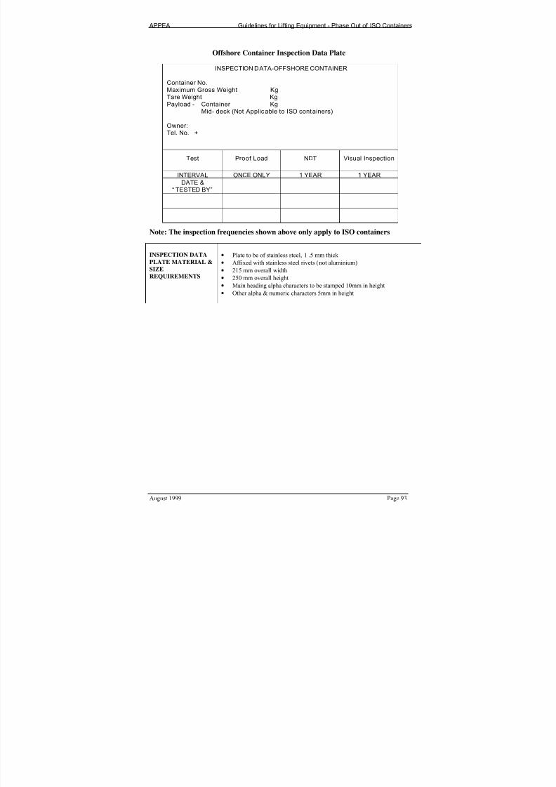
7/24/2019 APPEA Lifitng and Rigging Guidelines
http://slidepdf.com/reader/full/appea-lifitng-and-rigging-guidelines 95/109
APPEA Guidelines for Lifting Equipment - Phase Out of ISO Containers
August 1999 Page 93
Offshore Container Inspection Data Plate
INSPECTION DATA-OFFSHORE CONTAINER
Container No.
Maximum Gross Weight KgTare Weight KgPayload - Container Kg Mid- deck (Not Applicable to ISO containers)
Owner:Tel. No. +
Test Proof Load NDT Visual Inspection
INTERVAL ONCE ONLY 1 YEAR 1 YEAR
DATE &“ TESTED BY”
Note: The inspection frequencies shown above only apply to ISO containers
INSPECTION DATA
PLATE MATERIAL &
SIZE
REQUIREMENTS
• Plate to be of stainless steel, 1 .5 mm thick
• Affixed with stainless steel rivets (not aluminium)
• 215 mm overall width
• 250 mm overall height• Main heading alpha characters to be stamped 10mm in height
• Other alpha & numeric characters 5mm in height

7/24/2019 APPEA Lifitng and Rigging Guidelines
http://slidepdf.com/reader/full/appea-lifitng-and-rigging-guidelines 96/109
APPEA Guidelines for Lifting Equipment - Phase Out of ISO Containers
Page 94 August 1999
OK No
• Container was placed on supports and a full
underside inspection carried out.
• Container has no significant corrosion and/or structural faultaffecting integrity
• Container floor is in sound condition
• NDT of padeye welds and floor support structure
has not revealed any cracking (or repairs have
been effected)• Padeyes are fitted to the container
• Padeyes have engineering design drawings available
• Padeye design complies with the requirements of this
document.
• Container has been de-rated as per requirements of this
document
• Container has been load tested as per requirements of thisdocument
• There is no permanent distortion of the container following
load testing
• Forklift pocket marking is as per the requirements of this
document and the pockets are in a good and safe condition.
• Where a 5th
leg is used in a chain sling assembly, the chain in
the 5th
leg must meet ISO3076 standards for lifting chain.
CHECK LIST.
REVIEW PRIOR TO
ISSUING A TESTCERTIFICATE
• Engineering drawings and structural analysis support any
modifications. All such modifications should have
independent design verification.

7/24/2019 APPEA Lifitng and Rigging Guidelines
http://slidepdf.com/reader/full/appea-lifitng-and-rigging-guidelines 97/109
APPEA Guidelines for Lifting Equipment
August 1999 Page 95
APPENDIX I
GUIDELINES FOR THE INSPECTION, TESTING AND
MARKING OF OFFSHORE CONTAINERS

7/24/2019 APPEA Lifitng and Rigging Guidelines
http://slidepdf.com/reader/full/appea-lifitng-and-rigging-guidelines 98/109
APPEA Guidelines for Lifting Equipment - Inspection, Testing and Marking of Offshore Containers
Page 96 August 1999
PREAMBLE
The purpose of these guidelines is to address integrity requirements for existing offshore containers.
The guideline does not address requirements for new container fabrication. For information on new container
fabrication, refer to APPEA “Guidelines for Lifting Equipment”
Neither do these guidelines address concerns with the use of ISO containers within the offshore industry. For
ISO container management, refer to the APPEA Guideline for the Phase Out of ISO Shipping Containers.
These guidelines will provide guidance to lifting equipment testing facilities on consistent minimum quality
requirements for testing offshore containers.
APPEA encourages all offshore container owners and their agents to utilise inspection services that have been
accredited by NATA (or equivalent overseas organisations) to carry out inspections and/or tests in accordance
with this guideline.
If the required documentation needed to obtain a “Certificate of Conformity” as detailed within this guideline
is not available to support the integrity of the container to be inspected and/or tested, the container should not
be approved for offshore use. This may require that engineering drawings be developed and calculations
carried out to verify the design of the container as being fit for intended service. Without all required
information, a “Certificate of Conformity” should not be given for the container.

7/24/2019 APPEA Lifitng and Rigging Guidelines
http://slidepdf.com/reader/full/appea-lifitng-and-rigging-guidelines 99/109
APPEA Guidelines for Lifting Equipment - Inspection, Testing and Marking of Offshore Containers
August 1999 Page 97
DOCUMENT SCOPE Provide guidelines for the inspection, testing and marking of a widerange of containers, baskets, skips etc. used in the offshore oil & gasindustry.
INTRODUCTION The range of shapes, sizes and capacity of containers used in theoffshore industry makes it difficult to specify all requirements that need
to be met for each individual design.This document will provide specifics on some matters affecting safetyof containers whilst other areas may offer guidance only.It is the joint responsibility of both the equipment owner and theinspection and/or testing facility to ensure that all containers used
within the offshore industry are fit for the intended service.
REFERENCE
MATERIALAustralian Maritime Safety Authority, Marine Orders, Part 44, Section11
International Maritime Organization Circular 613 (to be replaced byMaritime Safety Committee, Circular 860)
DNV 2.7-1 Certification notes for Offshore ContainersAPPEA Guidelines for Lifting Equipment IMDG Code
PrEN12079. Offshore Containers – Design, construction, testing,inspection and marking.Petroleum Submerged Lands Act P(SL)AZOCA Regulations
COMMENTS ON
DESIGN OF
OFFSHORE
CONTAINERS
APPEA has recognised that there are many containers in use within the
Australian offshore oil & gas industry that may not be correctlyengineered for the service.The guidelines and procedures provided in this document will assist inensuring that every container used within the industry has engineeringdrawings and design calculations to support the Maximum GrossWeight indicated on the container.Without the required documentation the testing facility will have noready method of determining if the Maximum Gross Weight (MGW)nominated by the owner, is in fact a safe working load to be applied. New containers being fabricated will be to more stringent guidelinesand will be built to recognised standards such as DNV 2.7-1. This willautomatically provide the quality that this document seeks to introduceto existing containers.
JUSTIFICATION OF
ALLOWABLE MGW
(Maximum Gross
Weight) OF EXISTING
CONTAINERS
Existing containers may well need to be down-rated due to the morestringent testing now required.It is recommended that container owners carry out a review of existingdesign MGW ratings to ensure that the container(s) will meet thetesting requirements of 2.5 times MGW.
It may be necessary to revise the container MGW and to update
drawings as required, indicating new ratings.

7/24/2019 APPEA Lifitng and Rigging Guidelines
http://slidepdf.com/reader/full/appea-lifitng-and-rigging-guidelines 100/109
APPEA Guidelines for Lifting Equipment - Inspection, Testing and Marking of Offshore Containers
Page 98 August 1999
PADEYE
REQUIREMENTS
One of the most critical areas in the fabrication of an offshore container is the
padeyes and their attachment to the container. For this reason APPEA requires
that the following be met on all offshore containers.
The installation of padeyes must be carried out in accordance with good
engineering practices.• No “bolted on” padeyes are permitted
• Padeyes must be welded to the primary structure of the container
Note: For existing containers of mono-coque construction, a detailed
engineering assessment of the padeye connection is required.
• Design carried out by a qualified structural engineer and checked by an
independent engineer.
• For design purposes, the design load is to be carried on two diagonally
opposite padeyes.
• Align to centre of gravity of the loaded container.
• Shackle pin hole to be +3mm or, not greater than 4% more than the
shackle pin diameter
• Width of padeye to be equal to 75% of the opening of shackle to be fitted.This may be accomplished by fitting bosses (cheek plates) to padeye.
• Material traceability where appropriate material with through thickness
properties is to be specified. (Lamellar Defects)
• Documented welding procedures (To AS1554, AWSD1.1 etc.)
• Welder qualification trace-ability
• NDT inspection of welding by MPI for all fillet welds & a combination of
Ultra Sonic and MPI for full penetration welds. ( NATA to assist with text)
NOTES:
1. The installation of padeyes MUST have engineering trace-ability.
2. DNV 2.7-1 provides full details of container design and material
requirements and designers are encouraged to use the DNV document as a
guide.
GENERAL DESIGN
REQUIREMENTS• Mono-coque construction is not to be used in new offshore container
fabrication and/or designs. i.e.: A “Primary structure” is required.
• For all other design requirements for new offshore containers, refer toDNV2.7-1 “Certification Notes – Offshore Containers”.
.
MARKING
REQUIREMENTS
All Offshore containers shall have:
Marking plates for:
• Operational Marking Plate (Tare, Nett & Gross)
• Test Plate (date of tests and inspections)
“Other” marking requirements• Each container should be marked with a unique identification number
issued by the owner.
Notes:1. The above referenced “unique number” should be cross-referenced on all
relevant documentation, including the “Certificate of Conformity”.
2. The number should be prominently displayed on at least 2 sides of the
container in contrasting colours with stenciled characters of not less than
75 mm in height.

7/24/2019 APPEA Lifitng and Rigging Guidelines
http://slidepdf.com/reader/full/appea-lifitng-and-rigging-guidelines 101/109
APPEA Guidelines for Lifting Equipment - Inspection, Testing and Marking of Offshore Containers
August 1999 Page 99
COMMENTS ON
LOAD TESTING OF
OFFSHORE
CONTAINERS
The load test requirements for offshore containers used in Australian waters
have traditionally been taken from Marine Orders Part 32 as published by the
Australian Maritime Safety Authority.
The APPEA lifting equipment guideline committee have recognised that this
table is not suited to offshore containers and further recognise that it is therequirements of the International Maritime Organisation (IMO) that must beapplied.
IMO have issued a circular (613) that details testing requirements for offshore
containers.
This circular, referenced in Marine Orders part 44, paragraph 11 is to be
replaced by circular 860. (Both circulars have similar wording.)
LOAD TESTING Prior to load testing, carry out Thorough Visual Inspection as detailed within
this document.
(There is no value in testing a container that has defects)4 Point Lifting Test:
Internal Load (not to be hung under container): a uniformly distributed load,such that the combined tare of the container and test load is equal to 2.5 times
the rated MGW.
The container should be lifted with its lifting set attached to all four padeyes.
2 Point Lifting Test:
Internal load (not to be hung under container): a uniformly distributed load
such that the combined tare of the container and test load is equal to 1.5 timesthe rated MGW.
The container should be lifted with slings attached to two diagonally opposite
padeyes during the test.
DOCUMENTATION
REQUIREMENTSPRIOR TO
LOAD-TESTING
The following requirements apply to any offshore container including baskets,
bottle racks, waste skips, completion baskets, workshops, stores and any other structure used to transport goods to and from offshore facilities.
Prior to any container being load tested, the testing facility is required to make
all practical effort to ensure that the container is designed for the intended
loading and service.
The equipment owner is required to provide the testing facility with either a
classification society (e.g. DNV) approval for the container or, engineeringdrawings and a full design package completed by an engineer experienced in
the design of offshore containers.

7/24/2019 APPEA Lifitng and Rigging Guidelines
http://slidepdf.com/reader/full/appea-lifitng-and-rigging-guidelines 102/109
APPEA Guidelines for Lifting Equipment - Inspection, Testing and Marking of Offshore Containers
Page 100 August 1999
COMMENTARY ON
CLASSIFICATION
SOCIETY APPROVED
OFFSHORECONTAINERS
When a container with class society certification is presented to a NATA
accredited facility for inspection and/or load testing, the facility is not required
to verify the design.
The NATA accredited facility can proceed with load testing the container and issue the Certificate of Conformity on the strength of the Class SocietyCertification approval and the satisfactory load test.
The engineering drawings and design calculations detailed below are not
required to be presented to the inspection and/or testing facility for a class
society approved container.
Maintaining class society certification will provide acceptance of the container
at other locations throughout the world.
NATA ACCREDITED
FACILTY
RESPONSIBILITIES
When a container is presented to a NATA accredited facility for inspection
and testing according to APPEA requirements, the facility management must
recognise that they are playing a major role in ensuring the safety of offshore
containers.
ALLOWABLE
DEFLECTION
DURING &
SUBSEQUENT TO
LOAD TESTING
Allowable deflection limits are detailed within DNV 2.7-1 Certification notes
– Offshore Containers.
Refer to sections 3.7.1.2 7 3.7.1.3 of referenced DNV document.
COMMENTS ON
DEFLECTION
LIMITS
Where deflection exceeds the maximum allowable limit, the container should
be either, down-rated, repaired or scrapped.

7/24/2019 APPEA Lifitng and Rigging Guidelines
http://slidepdf.com/reader/full/appea-lifitng-and-rigging-guidelines 103/109
APPEA Guidelines for Lifting Equipment - Inspection, Testing and Marking of Offshore Containers
August 1999 Page 101
INFORMATION TO
BE INCLUDED IN
ENGINEERING
INFORMATION
As a minimum the engineering design drawings, calculations and
specifications supplied by the container owner (when container is notclass society approved) to the inspection and/or testing facility should
include:
• Name of ualified desi n en ineer.• Name of verifying engineer (Design to be verified by an
independent engineer)
• S ecification for materials to be used in fabrication• Desi n Tare Nett & Maximum Gross Wei ht ratin• Welding specifications, consumables and weld procedures to be
used
All welding to be continuous fillet weld (except where otherwisespecified) with size of weld to be equal to the thickness of the steel
being welded or 6mm whichever is the lesser. Notes:1. The welding methods, procedures and personnel qualifications,
details, workmanship, quality and inspection should be specified to be in accordance with a recognised standard
• Material traceability requirements (Critical for padeyes and platesto which padeyes attach and important for primary structuremembers)
• NDT Inspection requirements at time of fabrication. Note:Whilst not all the following NDT work may have been carried out onan older container, the NDT on padeye welds is considered to be
critical requirement1. Wall and floor welds to have 100% visual only.
2. Padeye butt welds – 100% UT/RT (prior to load test)3. Padeye fillet welds - 100% UT/ RT (prior to load test)
4. Padeye butt & fillet welds – 100% MPI after load testRe-weld to have 20% inspection as per original (NATA to assist)
• Pade es must be ali ned to the centre of ravit of the load.• Pade es must tie into the rimar structure• Padeye hole to be 3mm or not more than 4% greater than shackle
pin diameter.
• Padeye width to be 75% (minimum) of opening of shackle pindiameter. This may require that bosses be welded to padeye plate.
• Design of lifting set to be attached.
• Details of surface preparation prior to apply surface coatings
• Details of coatings to be applied to container

7/24/2019 APPEA Lifitng and Rigging Guidelines
http://slidepdf.com/reader/full/appea-lifitng-and-rigging-guidelines 104/109
APPEA Guidelines for Lifting Equipment - Inspection, Testing and Marking of Offshore Containers
Page 102 August 1999
SLINGS Sling sets may be chain or wire rope.
• Six sling assemblies are not allowed
• Chain used in stingers (or 5th
leg) must meet ISO 3076, or ISO 7593
standards.
SHACKLES Shackles must be:
• Grade “S” minimum
• Safety pin type with split pin fitted
• Bow shackles are preferred
CONTAINER
INSPECTIONS
Containers must receive a Thorough Visual Inspection both annually and
prior to any load testing.
• NDT Inspection of padeyes and floor support structure is to be carried out
every 3 years and prior to load testing.• All Thorough Visual Inspections and NDT inspections must be recorded
in a lifting equipment database.
THOROUGH VISUAL
& NDT INSPECTION
REQUIREMENTS
ANNUAL
REQUIREMENT
• Container is free from obvious defects, significant corrosion, impact
damage, cracks, etc.
• Under-floor support structure inspection.
• Place container on supports to allow full inspection of underside and
ensure adequate lighting.
• Look for extensive corrosion and/or any cracking.
• It may be necessary to sand blast corroded steel to allow full inspection.
• Suspected areas of cracking to have NDT inspections carried out.
• Steelwork that has suffered metal loss of 10% or greater throughcorrosion, is to be replaced.
Note: This may require UT checks to quantify metal loss.
• Complete structure to be examined for corrosion, cracking, and impact
damage. Particular attention is to be given to inspection of lifting points,
under-side members and corner post assemblies.
• Visually inspect all welds for defects.
• NDT all welds in padeye area. (3 yearly) NATA to advise type of NDT
• NDT a minimum of three each, selected under-floor structural welds
• Inspect for signs of mechanical damage.
• Doors, frames, seals, hinges, locks should be examined and functionally
checked to ensure satisfactory operation without undue force.
• Check floor is substantially flat with no signs of damage or other indications that may indicate overloading. Any internal floor damage may
indicate underside damage- re-check.
• Marking Plates should be as per requirements of this document.

7/24/2019 APPEA Lifitng and Rigging Guidelines
http://slidepdf.com/reader/full/appea-lifitng-and-rigging-guidelines 105/109
APPEA Guidelines for Lifting Equipment - Inspection, Testing and Marking of Offshore Containers
August 1999 Page 103
TESTING OF
WORKSHOP
CONTAINERS,
LOGGING UNITSETC.
In the past, it has proven most difficult (if not impossible) to fit the required
test weights into containers that have work benches, shelving etc.
It is also impossible to fit weights into many logging units and other container
style cabins that either are full of specialised equipment used by servicecompanies or, only have personnel access doors.
In the case of these units APPEA has considered several options & other
interested parties have put forward options for ensuring on-going integrity.
Hanging weights under the container does little to verify the integrity and the
weights can generally only be suspended from the strongest points. This does
nothing for ensuring integrity of lesser structural members.
APPEA therefore proposes that more stringent inspection requirements apply
to these units in lieu of any load testing.
6 YEARLYINSPECTION OF
WORKSHOP
CONTAINERS,
LOGGING UNITS
ETC.
Where test weights cannot be evenly distributed across the floor area of anycontainer, logging unit etc. the following inspection methods shall be used to
ensure the on-going integrity of the equipment.
These requirements shall be additional to the ANNUAL INSPECTION
requirements as detailed on page 9
Note: This method of integrity assurance will be in lieu of load testing and will
only be carried out by NATA accredited NDT inspection facilities.
• Place container on racks to allow full underside inspection.
Note: Do NOT walk underneath containers suspended by forklift or cranes.
• Abrasive blast 25% of under-floor welds.
• Carry out MPI on all welds cleaned by blasting
• If any cracking of welds or structural members is identified, abrasive blast
a further 25% and test as described above.
• Where continued cracking is found in the additional welds cleaned that
have been cleaned for inspection, the underside should be completely
abrasive cleaned and all welds inspected by MPI method.
• Carry out UT testing of 50% of under-side structural members. Note: If any metal loss of > 10% is detected, the remaining structural
members shall also be UT checked for metal loss.
• Carry out repairs as required using approved welding procedures,
qualified welders and trace-able materials equivalent to the original
structure members as detailed on the engineering drawings.
• Carry out MPI on all weld repairs and rectify any faults detected.
• Re-coat underside of container with a suitable coating for the offshore
environment.• NATA endorsed facility shall provide the equipment owner with a “stick
diagram” of the container underside. The diagram shall identify members
and joints inspected.
• The equipment owner should ensure that all QA documents relating to
repairs carried out are complied and retained on file for future reference.
Note: Whilst the abrasive blast requirements may, at first seem to be quite
extensive, it will, in most cases be advantageous as many containers will
require re-application of coatings (particularly underneath) at the end of 6years and this work will fit well with that requirement.

7/24/2019 APPEA Lifitng and Rigging Guidelines
http://slidepdf.com/reader/full/appea-lifitng-and-rigging-guidelines 106/109
APPEA Guidelines for Lifting Equipment - Inspection, Testing and Marking of Offshore Containers
Page 104 August 1999
VISUAL INSPECTOR
KNOWLEDGE
REQUIREMENTS
The inspector must have, as a minimum, a knowledge and adequate practicalexperience of:
• The statutory requirements relating to containers.
• The provisions of DNV 2.7-1
• The various types of containers in service.
• The correct methods of slinging and handling the containers.• The loads, stresses and strains affecting containers when handled under
adverse offshore conditions.
• The methods of testing containers as detailed in Maritime Safety.
Committee circular 860 or, DNV2.7-1 Offshore Container, Certification
Notes.
• Defects likely to be found in containers and acceptable levels of wear,distortion and deterioration in relation to safety in use.
• Welding methods and procedures and qualification of welders.
• The various methods of non-destructive examination (NDE) and a good
understanding of how they work and their limitations
• Techniques for measuring container to ensure distortion has not occurred
during service or load testing.
Offshore Container Identification Plate
OFFSHORE CONTAINER
Name of Manufacturer Month/year of Manufacture
Manufacturers Serial No.
Maximum Gross Weight Kg at deg sling angle
Tare Weight Kg
Payload Container Kg Intermediate Deck Kg
Certificate of Conformity No.
Design Temperature Degrees C
IDENTIFICATION
PLATE MATERIAL &
SIZE
REQUIREMENTS
• Plate to be of stainless steel, approximately 1 .5 mm thick
• Affixed with stainless steel rivets (not aluminium)
• 215 mm overall width• 150 mm overall height
• Main heading alpha characters to be stamped 10mm in height
• Other alpha & numeric characters 5mm in height

7/24/2019 APPEA Lifitng and Rigging Guidelines
http://slidepdf.com/reader/full/appea-lifitng-and-rigging-guidelines 107/109
APPEA Guidelines for Lifting Equipment - Inspection, Testing and Marking of Offshore Containers
August 1999 Page 105
Offshore Container Inspection Data Plate
INSPECTION DATA-OFFSHORE CONTAINER
Container No.Maximum Gross Weight (wt) Kg at deg, Sling angleTare Weight KgPayload - Container Kg Mid- deck Kg (Where Applicable)
Owner:Tel. No. +
DATE: DATE: DATE:
TEST TYPE: TEST TYPE: TEST TYPE:
TESTED BY: TESTED BY: TESTED BY:
DATE: DATE:
TEST TYPE: TEST TYPE:
TESTED BY:
DATE:
TEST TYPE:
TESTED BY:TESTED BY:
DATE: DATE: DATE:
TEST TYPE: TEST TYPE: TEST TYPE:
TESTED BY: TESTED BY: TESTED BY:
DATE:
TEST TYPE:
DATE:
TEST TYPE:
TESTED BY:
DATE:
TEST TYPE:
TESTED BY: TESTED BY:
DATE: DATE: DATE:
TEST TYPE: TEST TYPE: TEST TYPE:
TESTED BY: TESTED BY: TESTED BY:
INSPECTION DATA
PLATE MATERIAL &
SIZE
REQUIREMENTS
• Plate to be of stainless steel, approximately 1 .5 mm thick
• Affixed with stainless steel rivets (not aluminium)
• 215 mm overall width
• 250 mm overall height (approx.)
• Main heading alpha characters to be stamped 10mm in height
• Other alpha & numeric characters 5mm in height

7/24/2019 APPEA Lifitng and Rigging Guidelines
http://slidepdf.com/reader/full/appea-lifitng-and-rigging-guidelines 108/109
APPEA Guidelines for Lifting Equipment - Inspection, Testing and Marking of Offshore Containers
Page 106 August 1999
CERTIFICATE OF
CONFORMITY
At the completion of inspection, testing and marking compliance work the
NATA endorsed Certificate of Conformity (developed by APPEA in
conjunction with NATA) will be issued by a NATA accredited facility
In signing and approving the issue of a Certificate of Conformity the NATAaccredited facility will be advising the owners, users & transporters of the
container that the unit is “fit for intended service”.
Where doubt exists, the NATA facility should seek clarification from a
registered structural engineer, who is experienced in container design.
The Certificate of Conformity will remain current for the life of the container
provided no structural alterations are made.Any structural alterations will require the container to be re-assessed and a
new Certificate of Conformity to be issued.
ONGOINGINSPECTION & TEST
REPORTS
Ongoing, in-service reports will include the following as appropriate:• Visual Inspection Reports
• Load Test Reports
• Non Destructive Testing Reports

7/24/2019 APPEA Lifitng and Rigging Guidelines
http://slidepdf.com/reader/full/appea-lifitng-and-rigging-guidelines 109/109
APPEA Guidelines for Lifting Equipment - Inspection, Testing and Marking of Offshore Containers
OK No
• Engineering drawings have been reviewed by either:
• A Classification Society (e.g. DNV, ABS, Lloyds etc.)
• An independent Qualified Engineer
• NATA accredited facilities qualified engineer.
• Drawings meet the requirements detailed within this
document.
• Container was placed on supports and a full underside
inspection carried out.
• Container has no significant corrosion and/or structural fault
affecting integrity
• Container floor is in sound condition
• Engineering drawings and structural analysis support anymodifications.
• Padeyes are fitted to the container
• Padeyes have engineering design drawings available
• Padeye design complies with the requirements of this
document.
• Container has been de-rated as per requirements of this
document
• Container has been load tested as per requirements of this
document
•
• There is no permanent distortion of the container followingload testing (Refer to DNV 2.7-1, section 37.1.2 & 3.7.1.3)
• Forklift pockets marking is as per the requirements of this
document.
• No grade T chain is used in 5th
leg of a 5 leg assembly where
is there is no redundancy
REQUIREMENTS TO
BE MET PRIOR TO
ISSUING A
“CERTIFICATE of CONFORMITY”
• NDT of padeye welds, structural member welds and floor
support structure has not revealed any cracking (or repairs
have been effected)