Embed Size (px)
Citation preview
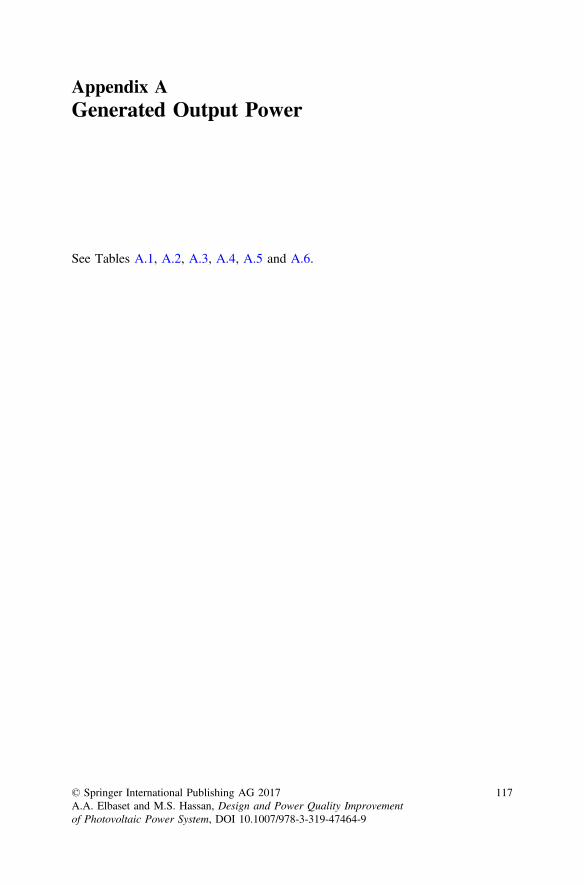
Appendix AGenerated Output Power
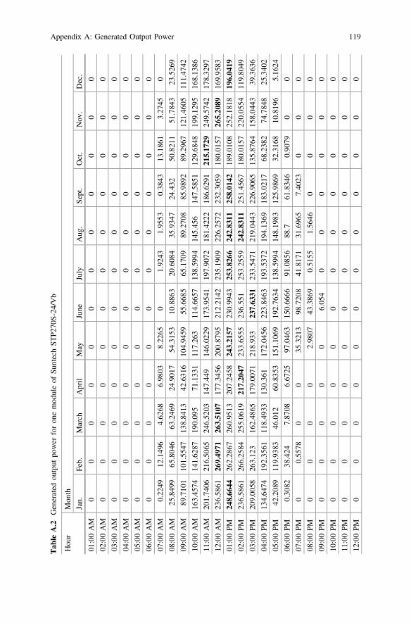
See Tables A.1, A.2, A.3, A.4, A.5 and A.6.
© Springer International Publishing AG 2017A.A. Elbaset and M.S. Hassan, Design and Power Quality Improvementof Photovoltaic Power System, DOI 10.1007/978-3-319-47464-9
117
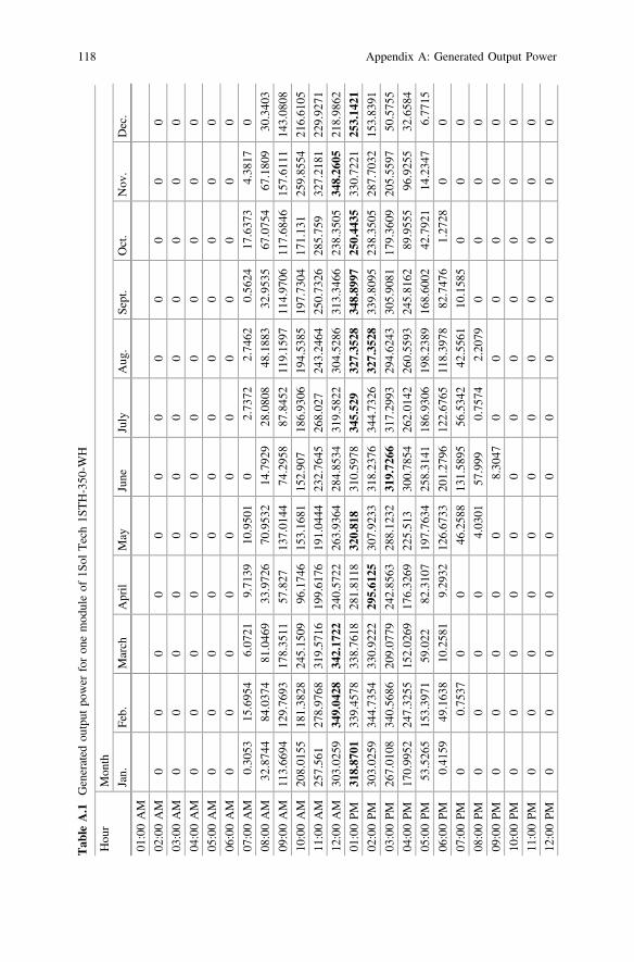
Tab
leA.1
Generated
output
power
foron
emod
uleof
1Sol
Tech1S
TH-350
-WH
Hou
rMon
th
Jan.
Feb.
March
April
May
June
July
Aug
.Sept.
Oct.
Nov
.Dec.
01:00AM
02:00AM
00
00
00
00
00
00
03:00AM
00
00
00
00
00
00
04:00AM
00
00
00
00
00
00
05:00AM
00
00
00
00
00
00
06:00AM
00
00
00
00
00
00
07:00AM
0.30
5315
.695
46.07
219.71
3910
.950
10
2.73
722.74
620.56
2417
.637
34.38
170
08:00AM
32.874
484
.037
481
.046
933
.972
670
.953
214
.792
928
.080
848
.188
332
.953
567
.075
467
.180
930
.340
3
09:00AM
113.66
9412
9.76
9317
8.35
1157
.827
137.01
4474
.295
887
.845
211
9.15
9711
4.97
0611
7.68
4615
7.61
1114
3.08
08
10:00AM
208.01
5518
1.38
2824
5.15
0996
.174
615
3.16
8115
2.90
718
6.93
0619
4.53
8519
7.73
0417
1.13
125
9.85
5421
6.61
05
11:00AM
257.56
127
8.97
6831
9.57
1619
9.61
7619
1.04
4423
2.76
4526
8.02
724
3.24
6425
0.73
2628
5.75
932
7.21
8122
9.92
71
12:00AM
303.02
5934
9.04
2834
2.17
2224
0.57
2226
3.93
6428
4.85
3431
9.58
2230
4.52
8631
3.34
6623
8.35
0534
8.26
0521
8.98
62
01:00PM
318.87
0133
9.45
7833
8.76
1828
1.81
1832
0.81
831
0.59
7834
5.52
932
7.35
2834
8.89
9725
0.44
3533
0.72
2125
3.14
2102
:00PM
303.02
5934
4.73
5433
0.92
2229
5.61
2530
7.92
3331
8.23
7634
4.73
2632
7.35
2833
9.80
9523
8.35
0528
7.70
3215
3.83
91
03:00PM
267.01
0834
0.56
8620
9.07
7924
2.85
6328
8.12
3231
9.72
6631
7.29
9329
4.62
4330
5.90
8117
9.36
0920
5.55
9750
.575
5
04:00PM
170.99
5224
7.32
5515
2.02
6917
6.32
6922
5.51
330
0.78
5426
2.01
4226
0.55
9324
5.81
6289
.955
596
.925
532
.658
4
05:00PM
53.526
515
3.39
7159
.022
82.310
719
7.76
3425
8.31
4118
6.93
0619
8.23
8916
8.60
0242
.792
114
.234
76.77
15
06:00PM
0.41
5949
.163
810
.258
19.29
3212
6.67
3320
1.27
9612
2.67
6511
8.39
7882
.747
61.27
280
0
07:00PM
00.75
370
046
.258
813
1.58
9556
.534
242
.556
110
.158
50
00
08:00PM
00
00
4.03
0157
.999
0.75
742.20
790
00
0
09:00PM
00
00
08.30
470
00
00
0
10:00PM
00
00
00
00
00
00
11:00PM
00
00
00
00
00
00
12:00PM
00
00
00
00
00
00
118 Appendix A: Generated Output Power
Tab
leA.2
Generated
output
power
foron
emod
uleof
SuntechST
P270
S-24
/Vb
Hou
rMon
th
Jan.
Feb.
March
April
May
June
July
Aug
.Sept.
Oct.
Nov
.Dec.
01:00AM
00
00
00
00
00
00
02:00AM
00
00
00
00
00
00
03:00AM
00
00
00
00
00
00
04:00AM
00
00
00
00
00
00
05:00AM
00
00
00
00
00
00
06:00AM
00
00
00
00
00
00
07:00AM
0.22
4912
.149
64.62
686.98
038.22
650
1.92
431.95
530.38
4313
.186
13.27
450
08:00AM
25.849
965
.804
663
.246
924
.901
754
.315
310
.886
320
.608
435
.934
724
.432
50.821
151
.784
323
.526
9
09:00AM
89.710
110
1.55
4713
8.84
1342
.631
610
4.94
5955
.668
565
.170
989
.270
885
.989
289
.296
712
1.46
0511
1.47
42
10:00AM
163.45
7414
1.62
8719
0.09
571
.133
111
7.26
311
4.66
5713
8.59
9414
5.45
614
7.58
5112
9.68
4819
9.12
9516
8.13
86
11:00AM
201.74
0621
6.50
6524
6.52
0314
7.44
914
6.02
2917
3.95
4119
7.90
7218
1.42
2218
6.62
9121
5.17
2924
9.57
4217
8.32
97
12:00AM
236.58
6126
9.49
7126
3.51
0717
7.34
5620
0.87
9521
2.21
4223
5.19
0922
6.25
7223
2.30
5918
0.01
5726
5.20
8916
9.95
83
01:00PM
248.66
4426
2.28
6726
0.95
1320
7.24
5824
3.21
5723
0.99
4325
3.82
6624
2.83
1125
8.01
4218
9.01
0825
2.18
1819
6.04
1902
:00PM
236.58
6126
6.25
8425
5.06
1921
7.20
4723
3.65
5523
6.55
125
3.25
5924
2.83
1125
1.45
6718
0.01
5722
0.05
5411
9.80
49
03:00PM
209.00
5826
3.12
316
2.48
6517
9.00
7121
8.93
323
7.63
3123
3.54
7121
9.04
4322
6.90
6513
5.87
6415
8.04
4339
.363
6
04:00PM
134.64
7419
2.35
6111
8.49
3313
0.36
117
2.04
5622
3.84
6319
3.53
7219
4.13
6918
3.02
1768
.238
274
.784
825
.340
2
05:00PM
42.208
911
9.93
8346
.012
60.835
315
1.10
6919
2.76
3413
8.59
9414
8.19
8312
5.98
6932
.316
810
.819
65.16
24
06:00PM
0.30
8238
.424
7.87
086.67
2597
.046
315
0.66
6691
.085
688
.761
.834
60.90
790
0
07:00PM
00.55
780
035
.321
398
.720
841
.817
131
.696
57.40
230
00
08:00PM
00
00
2.98
0743
.386
90.51
551.56
460
00
0
09:00PM
00
00
06.05
40
00
00
0
10:00PM
00
00
00
00
00
00
11:00PM
00
00
00
00
00
00
12:00PM
00
00
00
00
00
00
Appendix A: Generated Output Power 119
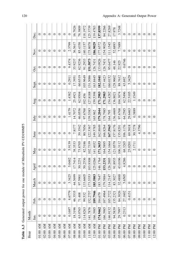
Tab
leA.3
Generated
output
power
foron
emod
uleof
Mitsub
ishi
PV-U
D19
0MF5
Hou
rMon
th
Jan.
Feb.
March
April
May
June
July
Aug
.Sept.
Oct.
Nov
.Dec.
01:00AM
00
00
00
00
00
00
02:00AM
00
00
00
00
00
00
03:00AM
00
00
00
00
00
00
04:00AM
00
00
00
00
00
00
05:00AM
00
00
00
00
00
00
06:00AM
00
00
00
00
00
00
07:00AM
0.16
978.67
793.34
255.04
825.91
390
1.41
791.43
820.29
119.43
742.37
990
08:00AM
18.319
646
.353
544
.569
917
.741
438
.353
37.81
7714
.707
225
.492
117
.395
135
.923
736
.561
716
.702
6
09:00AM
63.076
571
.408
97.590
130
.225
173
.870
539
.354
246
.055
662
.950
460
.651
962
.923
685
.435
878
.380
9
10:00AM
114.82
6399
.532
133.66
0550
.253
682
.518
680
.785
697
.676
810
2.45
610
3.96
4991
.293
314
0.11
5711
8.19
72
11:00AM
141.78
7615
2.27
5717
3.53
5310
3.93
0810
2.73
3912
2.53
6713
9.53
8312
7.81
8813
1.50
8615
1.58
7317
5.80
7812
5.37
39
12:00AM
166.39
8518
9.79
4618
5.58
0312
5.02
6614
1.40
3214
9.57
8516
5.96
215
9.53
9816
3.84
4512
6.74
3118
6.90
2911
9.47
83
01:00PM
174.94
6218
4.67
918
3.76
4714
6.17
6417
1.36
5316
2.88
4917
9.20
4417
1.29
8318
2.10
4113
3.09
2617
7.65
7213
7.85
9902
:00PM
166.39
8518
7.49
6417
9.58
8415
3.23
3116
4.58
9516
6.82
6417
8.79
8517
1.29
8317
7.44
2312
6.74
3115
4.90
2984
.226
6
03:00PM
146.91
3218
5.27
2211
4.21
4712
6.20
0515
4.16
6416
7.59
4316
4.79
515
4.42
8216
0.01
5295
.647
711
1.15
4527
.826
9
04:00PM
94.583
913
5.23
2183
.302
791
.893
512
1.05
7915
7.81
7613
6.44
6913
6.80
2112
8.96
0248
.146
52.689
317
.978
05:00PM
29.799
784
.302
632
.488
843
.019
610
6.31
1213
5.82
0197
.676
810
4.38
7488
.761
222
.925
7.74
893.72
48
06:00PM
0.23
1327
.160
25.65
054.82
8668
.326
510
6.11
7664
.258
562
.549
643
.692
0.67
460
0
07:00PM
00.41
510
025
.020
169
.581
829
.646
322
.510
55.34
290
00
08:00PM
00
00
2.17
1130
.727
80.38
891.15
490
00
0
09:00PM
00
00
04.37
960
00
00
0
10:00PM
00
00
00
00
00
00
11:00PM
00
00
00
00
00
00
12:00PM
00
00
00
00
00
00
120 Appendix A: Generated Output Power
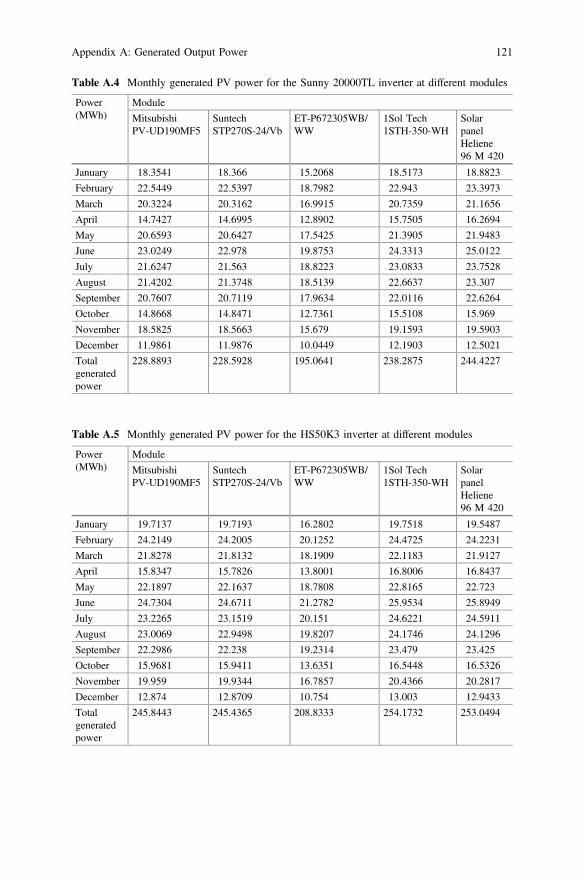
Table A.4 Monthly generated PV power for the Sunny 20000TL inverter at different modules
Power(MWh)
Module
MitsubishiPV-UD190MF5
SuntechSTP270S-24/Vb
ET-P672305WB/WW
1Sol Tech1STH-350-WH
SolarpanelHeliene96 M 420
January 18.3541 18.366 15.2068 18.5173 18.8823
February 22.5449 22.5397 18.7982 22.943 23.3973
March 20.3224 20.3162 16.9915 20.7359 21.1656
April 14.7427 14.6995 12.8902 15.7505 16.2694
May 20.6593 20.6427 17.5425 21.3905 21.9483
June 23.0249 22.978 19.8753 24.3313 25.0122
July 21.6247 21.563 18.8223 23.0833 23.7528
August 21.4202 21.3748 18.5139 22.6637 23.307
September 20.7607 20.7119 17.9634 22.0116 22.6264
October 14.8668 14.8471 12.7361 15.5108 15.969
November 18.5825 18.5663 15.679 19.1593 19.5903
December 11.9861 11.9876 10.0449 12.1903 12.5021
Totalgeneratedpower
228.8893 228.5928 195.0641 238.2875 244.4227
Table A.5 Monthly generated PV power for the HS50K3 inverter at different modules
Power(MWh)
Module
MitsubishiPV-UD190MF5
SuntechSTP270S-24/Vb
ET-P672305WB/WW
1Sol Tech1STH-350-WH
SolarpanelHeliene96 M 420
January 19.7137 19.7193 16.2802 19.7518 19.5487
February 24.2149 24.2005 20.1252 24.4725 24.2231
March 21.8278 21.8132 18.1909 22.1183 21.9127
April 15.8347 15.7826 13.8001 16.8006 16.8437
May 22.1897 22.1637 18.7808 22.8165 22.723
June 24.7304 24.6711 21.2782 25.9534 25.8949
July 23.2265 23.1519 20.151 24.6221 24.5911
August 23.0069 22.9498 19.8207 24.1746 24.1296
September 22.2986 22.238 19.2314 23.479 23.425
October 15.9681 15.9411 13.6351 16.5448 16.5326
November 19.959 19.9344 16.7857 20.4366 20.2817
December 12.874 12.8709 10.754 13.003 12.9433
Totalgeneratedpower
245.8443 245.4365 208.8333 254.1732 253.0494
Appendix A: Generated Output Power 121
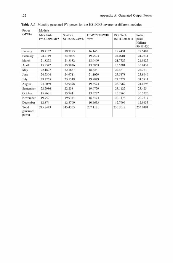
Table A.6 Monthly generated PV power for the HS100K3 inverter at different modules
Power(MWh)
Module
MitsubishiPV-UD190MF5
SuntechSTP270S-24/Vb
ET-P672305WB/WW
1Sol Tech1STH-350-WH
SolarpanelHeliene96 M 420
January 19.7137 19.7193 16.146 19.4431 19.5487
February 24.2149 24.2005 19.9593 24.0901 24.2231
March 21.8278 21.8132 18.0409 21.7727 21.9127
April 15.8347 15.7826 13.6863 16.5381 16.8437
May 22.1897 22.1637 18.6261 22.46 22.723
June 24.7304 24.6711 21.1029 25.5478 25.8949
July 23.2265 23.1519 19.9849 24.2374 24.5911
August 23.0069 22.9498 19.6574 23.7969 24.1296
September 22.2986 22.238 19.0729 23.1122 23.425
October 15.9681 15.9411 13.5227 16.2863 16.5326
November 19.959 19.9344 16.6474 20.1173 20.2817
December 12.874 12.8709 10.6653 12.7999 12.9433
Totalgeneratedpower
245.8443 245.4365 207.1121 250.2018 253.0494
122 Appendix A: Generated Output Power
Appendix BMATLAB/Simulink Models
See Figs. B.1, B.2, B.3 and B.4.
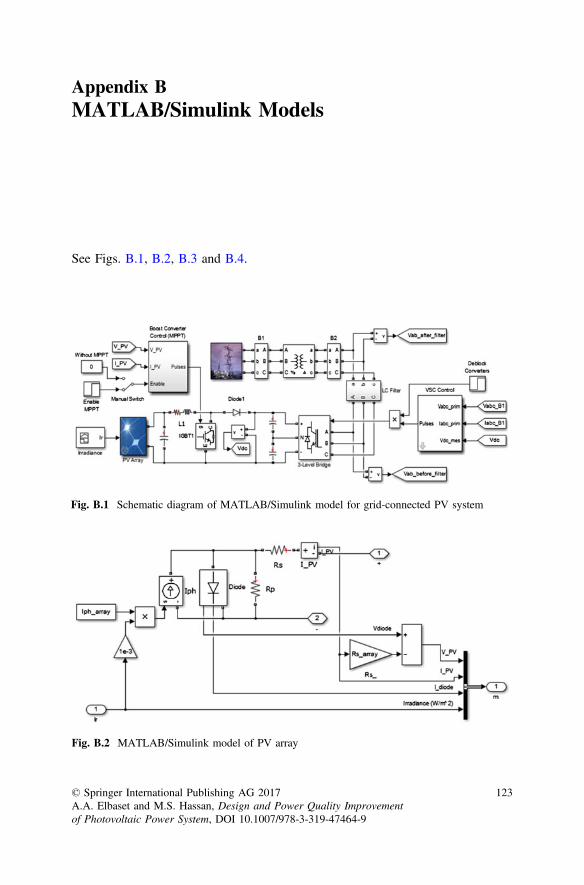
Fig. B.1 Schematic diagram of MATLAB/Simulink model for grid-connected PV system
Fig. B.2 MATLAB/Simulink model of PV array
© Springer International Publishing AG 2017A.A. Elbaset and M.S. Hassan, Design and Power Quality Improvementof Photovoltaic Power System, DOI 10.1007/978-3-319-47464-9
123
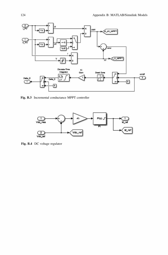
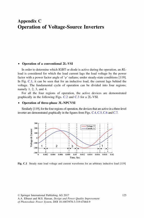
Fig. B.3 Incremental conductance MPPT controller
Fig. B.4 DC voltage regulator
124 Appendix B: MATLAB/Simulink Models
Appendix COperation of Voltage-Source Inverters
• Operation of a conventional 2L-VSI
In order to determine which IGBT or diode is active during the operation, an RL-load is considered for which the load current lags the load voltage by the powerfactor with a power factor angle of ‘φ’ radians; under steady-state conditions [119].In Fig. C.1, it can be seen that for an inductive load, the current lags behind thevoltage. The fundamental cycle of operation can be divided into four regions;namely 1, 2, 3, and 4.
For all the four regions of operation, the active devices are demonstratedgraphically in the following Figs. C.2 and C.3 for a 2L-VSI.
• Operation of three-phase 3L-NPCVSI
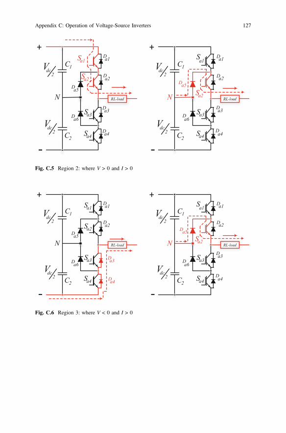
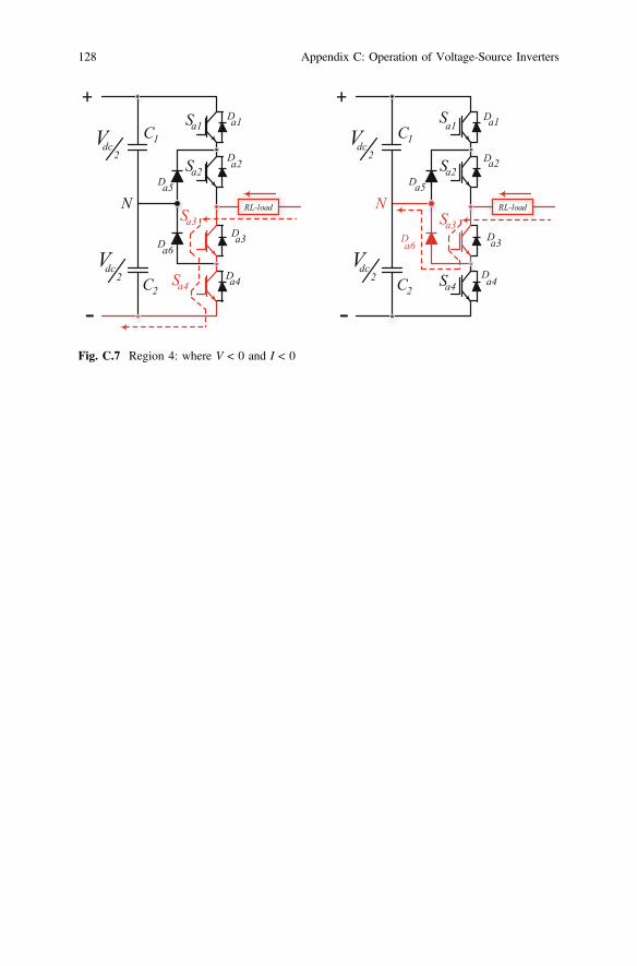
Similarly [119], for the four regions of operation, the devices that are active in a three-levelinverter are demonstrated graphically in the figures from Figs. C.4, C.5, C.6 and C.7.
Fig. C.1 Steady state load voltage and current waveforms for an arbitrary inductive load [119]
© Springer International Publishing AG 2017A.A. Elbaset and M.S. Hassan, Design and Power Quality Improvementof Photovoltaic Power System, DOI 10.1007/978-3-319-47464-9
125
+
dcV
Ssw2
Da1
Da2
-
Ssw1
Ssw2
Da1
Da2
Ssw1
-load
+
dcV
-
(a) (b)
RL-load RL
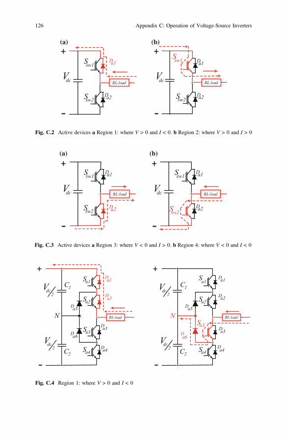
Fig. C.2 Active devices a Region 1: where V > 0 and I < 0. b Region 2: where V > 0 and I > 0
Ssw2
Da1
Da2
Ssw1
-load
+
dcV
-Ssw2
Da1
Da2
Ssw1
RL-load
+
dcV
-
(a) (b)
RL
Fig. C.3 Active devices a Region 3: where V < 0 and I > 0. b Region 4: where V < 0 and I < 0
+
dcV2
dcV2
Sa3
Sa2
Sa1
Sa4
Da1
Da2
Da3
Da4
Da5
Da6
N
-
C1
C2
-load
+
dcV2
dcV2
Sa3
Sa2
Sa1
Sa4
Da1
Da2
Da3
Da4
Da5
Da6
N
-
C1
C2
-loadRL RL
Fig. C.4 Region 1: where V > 0 and I < 0
126 Appendix C: Operation of Voltage-Source Inverters
+
dcV2
dcV2
Sa3
Sa2
Sa1
Sa4
Da1
Da2
Da3
Da4
Da5
Da6
N
-
C1
C2
-load
+
dcV2
dcV2
Sa3
Sa2
Sa1
Sa4
Da1
Da2
Da3
Da4
Da5
Da6
N
-
C1
C2
-loadRL RL
Fig. C.5 Region 2: where V > 0 and I > 0
+
dcV2
dcV2
Sa3
Sa2
Sa1
Sa4
Da1
Da2
Da3
Da4
Da5
Da6
N
-
C1
C2
RL-load
+
dcV2
dcV2
Sa3
Sa2
Sa1
Sa4
Da1
Da2
Da3
Da4
Da5
Da6
N
-
C1
C2
RL-load
Fig. C.6 Region 3: where V < 0 and I > 0
Appendix C: Operation of Voltage-Source Inverters 127
+
dcV2
dcV2
Sa3
Sa2
Sa1
Sa4
Da1
Da2
Da3
Da4
Da5
Da6
N
-
C1
C2
RL-load
+
dcV2
dcV2
Sa3
Sa2
Sa1
Sa4
Da1
Da2
Da3
Da4
Da5
Da6
N
-
C1
C2
RL-load
Fig. C.7 Region 4: where V < 0 and I < 0
128 Appendix C: Operation of Voltage-Source Inverters
Appendix DSimElectronics® MATLAB ToolboxOverview
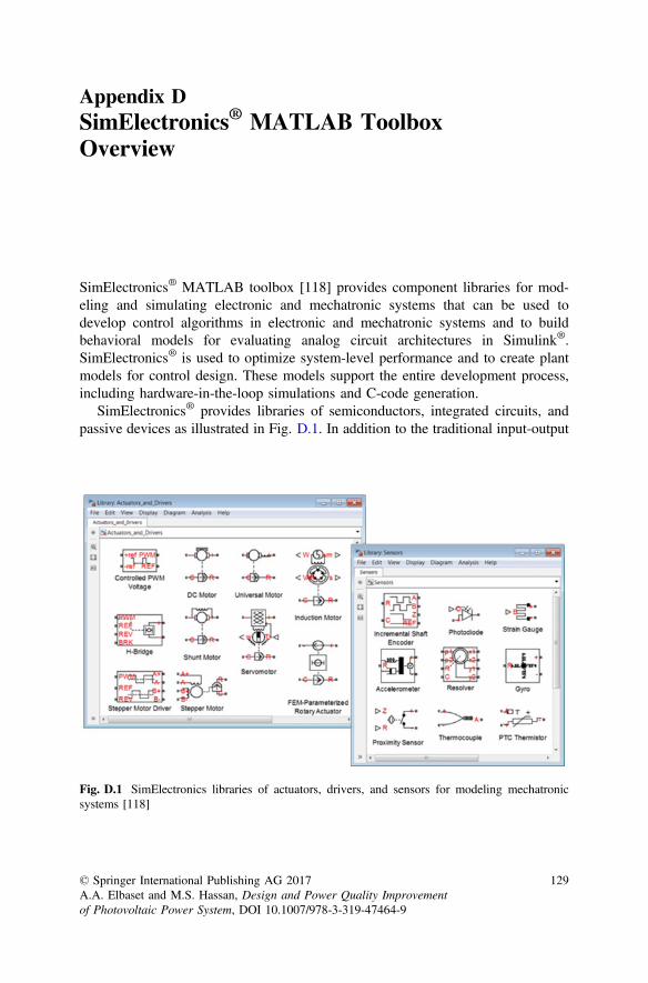
SimElectronics® MATLAB toolbox [118] provides component libraries for mod-eling and simulating electronic and mechatronic systems that can be used todevelop control algorithms in electronic and mechatronic systems and to buildbehavioral models for evaluating analog circuit architectures in Simulink®.SimElectronics® is used to optimize system-level performance and to create plantmodels for control design. These models support the entire development process,including hardware-in-the-loop simulations and C-code generation.
SimElectronics® provides libraries of semiconductors, integrated circuits, andpassive devices as illustrated in Fig. D.1. In addition to the traditional input-output
Fig. D.1 SimElectronics libraries of actuators, drivers, and sensors for modeling mechatronicsystems [118]
© Springer International Publishing AG 2017A.A. Elbaset and M.S. Hassan, Design and Power Quality Improvementof Photovoltaic Power System, DOI 10.1007/978-3-319-47464-9
129
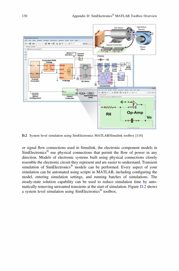
or signal flow connections used in Simulink, the electronic component models inSimElectronics® use physical connections that permit the flow of power in anydirection. Models of electronic systems built using physical connections closelyresemble the electronic circuit they represent and are easier to understand. Transientsimulation of SimElectronics® models can be performed. Every aspect of yoursimulation can be automated using scripts in MATLAB, including configuring themodel, entering simulation settings, and running batches of simulations. Thesteady-state solution capability can be used to reduce simulation time by auto-matically removing unwanted transients at the start of simulation. Figure D.2 showsa system level simulation using SimElectronics® toolbox.
D.2 System level simulation using SimElectronics MATLAB/Simulink toolbox [118]
130 Appendix D: SimElectronics® MATLAB Toolbox Overview
References
1. R. Y. Georgy and A. T. Soliman, Mediterranean and National Strategies for SustainableDevelopment Priority Field of Action 2: Energy and Climate Change, Energy Efficiencyand Renewable Energy, Egypt’s National Study, Final Report, Plan Bleu, Regional ActivityCentre, March 2007.
2. Ministry of Electricity and Energy, New and Renewable Energy Authority (NREA),Annual Report 2010/2011.
3. Hong Soo Goh, “The Effect of Grid Operating Conditions on The Harmonic Performanceof Grid-Connected PV Inverters,” Ph.D. Thesis, School of Electrical, Electronic &Computer Engineering, Newcastle University, September 2011.
4. REN21, “Renewables Global Futures Report, in Renewable Energy Policy Network for the21st Century 2013” Paris, France 2013.
5. Walid Omran, “Performance Analysis of Grid-Connected Photovoltaic Systems,” Ph.D.Thesis, Electrical and Computer Engineering, University of Waterloo, Waterloo, Ontario,Canada, 2010.
6. A. Al-Salaymeh, Z. Al-Hamamre, F. Sharaf, and M. R. Abdelkader, “Technical andEconomical Assessment of the Utilization of Photovoltaic Systems in ResidentialBuildings: The Case of Jordan,” Energy Conversion and Management, vol. 51, no. 8,pp. 1719-1726, August 2010.
7. I. S. Kim, M. B. Kim and M. J. Youn, “New Maximum Power Point Tracker using SlidingMode Observer for Estimation of Solar Array Current in The Grid-Connected PhotovoltaicSystem,” in IEEE Transactions on Industrial Electronics, vol. 53, no. 4, pp. 1027-1035,June 2006.
8. P. E. Posedly, “Modelling and Analysis of Photovoltaic Generation and Storage Systemsfor Residential Use,” M.Sc. Thesis, Department of Electrical and Computer Engineering,College of Engineering, University of Cincinnati, June 2008.
9. V. L. Brano, A. Orioli, G. Ciulla, and A. Di Gangi, “An Improved Five-Parameter Modelfor Photovoltaic Modules,” Solar Energy Materials and Solar Cells, vol. 94, no. 8,pp. 1358–1370, August 2010.
10. R. Banos, F. Manzano-Agugliaro, F. G. Montoya, C. Gil, A. Alcayde, and J. Gomez,“Optimization Methods Applied to Renewable and Sustainable Energy: A review,”Renewable and Sustainable Energy Reviews, vol. 15, no. 4, pp. 1753–1766, May 2011.
11. G. Vidican, “Building Domestic Capabilities in Renewable Energy. A Case Study ofEgypt,” German Development Institute, Studies Series no. 66 Bonn, August 2012.
12. A. S. Bahaj, “Photovoltaic Roofing: Issues of Design and Integration into Buildings,”Renewable Energy, vol. 28, no. 14, pp. 2195–2204, November 2003.
13. D. G. f. Sonnenenergie, Planning and Installing Photovoltaic Systems: A Guide forInstallers, Architects and Engineers, 2nd ed., London, UK: Earthscan from Routledge,2008.
© Springer International Publishing AG 2017A.A. Elbaset and M.S. Hassan, Design and Power Quality Improvementof Photovoltaic Power System, DOI 10.1007/978-3-319-47464-9
131
14. J. Hossain and A. Mahmud, Renewable Energy Integration: Challenges and Solutions:Springer Science & Business Media, 2014.
15. R. A. Messenger and J. Ventre, Photovoltaic Systems Engineering, 2nd ed., Taylor &Francis, 2004.
16. S.B. Kjaer, J.K. Pedersen, F. Blaabjerg, “A Review of Single-Phase Grid-ConnectedInverters for Photovoltaic Modules” IEEE Transactions on Industry Applications, vol. 41,no. 5, pp. 1292–1306, September/October 2005.
17. B. Ho, H. Chung, “An Integrated Inverter With Maximum Power Tracking forGrid-Connected PV Systems,” IEEE Transactions on Power Electronics, vol. 20, no. 4,July 2005.
18. C. Hua and J. Lin, “AModified Tracking Algorithm for Maximum Power Tracking of SolarArray,” Energy Conversion and Management, vol. 45, no. 6, pp. 911–925, April 2004.
19. H. Gonçalves, M. Hlaili, H. Amira, H. Mechergui, and J. L. Afonso, “Simulation Results ofA 1 kW Photovoltaic System with MPPT Function in The Inverter,`̀ in Annual Seminar onAutomation, Industrial Electronics and Instrumentation (SAAEI’12), pp. 420–424, July2012.
20. N. Femia, G. Petrone, G. Spagnuolo, and M. Vitelli, “A Technique for ImprovingP&O MPPT Performances of Double-Stage Grid-Connected Photovoltaic Systems,” IEEETransactions on Industrial Electronics, vol. 56, no. 11, pp. 4473–4482, November 2009.
21. B. Blazic, I. Papic, “Advanced Control of A Converter Used for Connection of PhotovoltaicModules,” IEEE Power Engineering Society General Meeting 2006, Montreal, Quebec,2006.
22. F. Blaabjerg, R. Teodorescu, M. Liserre, A.V. Timbus, “Overview of Control and GridSynchronization for Distributed Power Generation Systems,” IEEE Transactions onIndustrial Electronics, vol. 53, no. 5, pp. 1398–1409, October 2006.
23. J. Kwon, K. Nam, B. Kwon, “Photovoltaic Power Conditioning System With LineConnection,” IEEE Transactions On Industrial Electronics, vol. 53, no. 4, August 2006.
24. S. Alepuz, S. Busquets-Monge, J. Bordonau, J. Gago, D. Gonzalez, and J. Balcells,“Interfacing Renewable Energy Sources to the Utility Grid Using a Three-Level Inverter,”IEEE Transactions on Industrial Electronics, vol. 53, no. 5, pp. 1504–1511, October 2006.
25. IEEE Recommended Practice for Utility Interface of Photovoltaic (PV) Systems, IEEE Std.929-2000, 2000.
26. T.F. Wu, C.H. Chang, Y.K. Chen, “A Multi-Function Photovoltaic Power Supply Systemwith Grid-Connection and Power Factor Correction Features,” in 31st Annual PowerElectronics Specialists Conference (PESC 2000), vol. 3, pp. 1185–1190, Galway, Ireland,June 18–23, 2000.
27. M.I. Marei, E.F. El-Saadany, M.M.A. Salama, “A Novel Control Algorithm for The DGInterface to Mitigate Power Quality Problems,” IEEE Transactions on Power Delivery, vol.19, no. 3, pp. 1384–1392, July 2004.
28. Wu Libo; Zhao Zhengming; Liu Jianzheng, “A Single-Stage Three-Phase Grid-ConnectedPhotovoltaic System With Modified MPPT Method and Reactive Power Compensation,”IEEE Transactions On Energy Conversion, vol. 22, no. 4, December 2007.
29. C.V Nayar; M. Ashari; W.W.L. Keerthipala, “A Grid-Interactive PhotovoltaicUninterruptible Power Supply System using Battery Storage and A Back Up DieselGenerator,” IEEE Transaction on Energy Conversion, vol. 15, no. 3, pp. 348–353,September 2000.
30. J. Carrasco, L. Franquelo, J. Bialasiewicz, E. Galván, R. Guisado, M. Prats, J. León, N.Moreno-Alfonso, “Power-Electronic Systems for the Grid Integration of Renewable EnergySources: A Survey,” IEEE Transactions on Industrial Electronics, vol. 53, no. 4, August2006.
31. A. Pregelj, M. Begovic, A. Rohatgi, “Impact of Inverter Configuration on PV SystemReliability and Energy Production,” IEEE 29th Photovoltaic Specialists Conference, May19–24, 2002.
132 References
32. M. Calais, J. Myrzik, T. Spooner, V. Agelidis, “Inverters for Single-Phase Grid-ConnectedPhotovoltaic Systems-An Overview,” in 33rd Annual Power Electronics SpecialistsConference, PESC02, pp. 1995–2000, Cairns, Qld., June 23–27, 2002.
33. J. Myrzik, M. Calais, “String and Module Integrated Inverters for Single-Phase GridConnected Photovoltaic Systems—A Review,” IEEE Bologna Power Tech ConferenceProceedings, vol. 2, Bologna, Italy, June 23–26, 2003.
34. Industrial Modernization Center (IMC) Website. [Online] Available from (http://www.imc-egypt.org/pgmenergy.asp) [Accessed Jan, 2014].
35. J. Samimi, E. A. Soleimani, and M. S. Zabihi, “Optimal Sizing of Photovoltaic Systems inVaried Climates,” Solar Energy, vol. 60, no. 2, pp. 97–107, February 1997.
36. J. C. Hernández, P. G. Vidal, and G. Almonacid, “Photovoltaic in Grid-ConnectedBuildings, Sizing and Economic Analysis,” Renewable Energy, vol. 15, no. 1, pp. 562–565,September 1998.
37. R. Haas, M. Ornetzeder, K. Hametner, A. Wroblewski, and M. Hubner, “Socio-EconomicAspects of The Austrian 200 kWp Photovoltaic-Rooftop Program,” Solar Energy, vol. 66,no. 3, pp. 183–191, June 1999.
38. N. K. Bansal and S. Goel, “Integration of Photovoltaic Technology in Cafeteria Building, atIndian Institute of Technology, New Delhi,” Renewable Energy, vol. 19, no. 1, pp. 65–70,January 2000.
39. X. Gong and M. Kulkarni, “Design Optimization of A Large Scale Rooftop PhotovoltaicSystem,” Solar Energy, vol. 78, no. 3, pp. 362–374, March 2005.
40. H. H. El-Tamaly and A. A. Elbaset, “Performance and Economic Study ofInterconnected PV System with Electric Utility Accompanied with Battery Storage,” in11th International Middle East Power Systems Conference, MEPCON’2006, pp. 328–333,El-Minia, Egypt, December 19–21, 2006.
41. D A. Fernandez-Infantes, J. Contreras, and J. L. Bernal-Agustin, “Design of GridConnected PV Systems Considering Electrical, Economical and Environmental Aspects: APractical Case,” Renewable Energy, vol. 31, no. 13, pp. 2042–2062, October 2006.
42. Li C-H, Zhu X-J, Cao G-Y, Sui S, Hu M-R., “Dynamic Modeling and Sizing Optimizationof Stand-alone Photovoltaic Power Systems using Hybrid Energy Storage Technology,”Renewable Energy, vol. 34, no. 3, pp. 815–826, March 2009.
43. A. Mellit, S. A. Kalogirou, L. Hontoria, and S. Shaari, “Artificial Intelligence Techniquesfor Sizing Photovoltaic Systems: A review,” Renewable and Sustainable Energy Reviews,vol. 13, no. 2, pp. 406–419, February 2009.
44. H. Ren, W. Gao, and Y. Ruan, “Economic Optimization and Sensitivity Analysis ofPhotovoltaic System in Residential Buildings,” Renewable Energy, vol. 34, no. 3, pp. 883–889, March 2009.
45. D Kornelakis A, Koutroulis E., “Methodology for The Design Optimization and TheEconomic Analysis of Grid-Connected Photovoltaic Systems,” IET Transactions onRenewable Power Generation, vol. 3, no. 4, pp. 476–492, December 2009.
46. Kornelakis A, Marinakis Y., “Contribution for Optimal Sizing of Grid-connectedPV-Systems Using PSO,” Renewable Energy, vol. 35, no. 6, pp. 1333–1341, June 2010.
47. A. Kornelakis, “Multiobjective Particle Swarm Optimization for The Optimal Design ofPhotovoltaic Grid-Connected Systems,” Solar Energy, vol. 84, no. 12, pp. 2022–2033,December 2010.
48. H. Suryoatmojo, A. Elbaset, A. Syafaruddin, and T. Hiyama, “Genetic Algorithm BasedOptimal Sizing of PV-Diesel-Battery System Considering CO2 Emission and Reliability,”International Journal of Innovative Computing Information and Control, vol. 6, no. 10,pp. 4631–4649, October 2010.
49. W. Muneer, K. Bhattacharya, and C. A. Cañizares, “Large-Scale Solar PV InvestmentModels, Tools, and Analysis: The Ontario Case,” IEEE Transaction on Power Systems, vol.26, no. 4, pp. 2547–2555, April 2011.
References 133
50. D. H. W. Li, K. L. Cheung, T. N. T. Lam, and W. W. H. Chan, “A Study of Grid-connectedPhotovoltaic (PV) System in Hong Kong,” Applied Energy, vol. 90, no. 1, pp. 122–127,February 2012.
51. D C. O. C. Oko, E. O. Diemuodeke, E. O. Omunakwe, and E. Nnamdi, “Design andEconomic Analysis of a Photovoltaic System: A Case Study,” International Journal ofRenewable Energy Development (IJRED), vol. 1, no. 3, pp. 65–73, August 2012.
52. E.D. Mehleri, H. Sarimveis, N.C. Markatos, and L.G. Papageorgiou, “Optimal Design andOperation of Distributed Energy Systems: Application to Greek Residential Sector,”Renewable Energy, vol. 51, pp. 331–342, March 2013.
53. M. Prodanović and T. C. Green, “Control and Filter Design of Three-Phase Inverters forHigh Power Quality Grid Connection,” IEEE Transactions on Power Electronics, vol. 18,no. 1, pp. 373-380, January 2003.
54. A. R. Oliva and J. C. Balda, “A PV Dispersed Generator: A Power Quality Analysis withinThe IEEE 519,” IEEE Transactions on Power Delivery, vol. 18, no. 2, pp. 525–530, April2003.
55. A. Sannino, J. Svensson, and T. Larsson, “Power-Electronic Solutions to Power QualityProblems,” Electric Power Systems Research, vol. 66, no. 1, pp. 71–82, July 2003.
56. Y. Li, D. M. Vilathgamuwa, and P. C. Loh, “Microgrid Power Quality Enhancement usingA Three-Phase Four-Wire Grid-Interfacing Compensator,” IEEE Transactions on IndustryApplications, vol. 41, no. 6, pp. 1707–1719, November/December 2005.
57. R. Teichmann and S. Bernet, “A Comparison of Three-Level Converters Versus Two-LevelConverters for Low-Voltage Drives, Traction, and Utility Applications,” IEEETransactions on Industry Applications, vol. 41, no. 3, pp. 855–865, May/June 2005.
58. S. Busquets-Monge, J. Rocabert, P. Rodríguez, S. Alepuz, and J. Bordonau, “MultilevelDiode-Clamped Converter for Photovoltaic Generators with Independent Voltage Controlof Each Solar Array,” IEEE Transactions on Industrial Electronics, vol. 55, no. 7,pp. 2713–2723, July 2008.
59. C. J. Gajanayake, D. M. Vilathgamuwa, P. C. Loh, R. Teodorescu, and F. Blaabjerg,“Z-Source-Inverter-Based Flexible Distributed Generation System Solution for Grid PowerQuality Improvement,” IEEE Transactions on Energy Conversion, vol. 24, no. 4, pp. 695–704, September 2009.
60. D. Geibel, T. Degner, C. Hardt, M. Antchev, and A. Krusteva, “Improvement of PowerQuality and Reliability with Multifunctional PV-Inverters in Distributed Energy Systems,”in 10th International Conference on Electrical Power Quality and Utilisation, EPQU 2009,pp. 1–6, Lodz, Poland; September 15–17, 2009..
61. S. H. Hosseini, M. Sarhangzadeh, M. B. Sharifian, and F. Sedaghati, “Using PV inDistribution Network to Supply Local Loads and Power Quality Enhancement,”International Conference on Electrical and Electronics Engineering, ELECO 2009,pp. I-249-I-253, Bursa, Turkey, November 5–8, 2009.
62. Hu Y, Chen Z, Excell P. “Power Quality Improvement of Unbalanced Power System withDistributed Generation Units” In Proceedings of the IEEE International Conference onElectric Utility Deregulation and Restructuring and Power Technologies, pp. 417–423,Weihai, Shandong, China; July 6–9, 2011.
63. F. Wang, J. L. Duarte, and M. A. Hendrix, “Grid-interfacing converter systems withenhanced voltage quality for microgrid application—concept and implementation,” IEEETransactions on Power Electronics, vol. 26, no. 12, pp. 3501–3513, December 2011.
64. R. Bojoi, L. R. Limongi, D. Roiu, and A. Tenconi, “Enhanced Power Quality ControlStrategy for Single-Phase Inverters in Distributed Generation Systems,” IEEE Transactionson Power Electronics, vol. 26, no. 3, pp. 798–806, March 2011.
65. V. Kamatchi Kannan and N. Rengarajan, “Photovoltaic Based Distribution StaticCompensator for Power Quality Improvement,” Electrical Power and Energy Systems,vol. 42, no. 1, pp. 685–692, November 2012.
134 References
66. J. Mahdavi, A. Emaadi, M. Bellar, and M. Ehsani, “Analysis of Power ElectronicConverters using The Generalized State-Space Averaging Approach,” IEEE Transactionson Circuits and Systems I: Fundamental Theory and Applications, vol. 44, no. 8, pp. 767–770, August 1997.
67. A. Reatti and M. K. Kazimierczuk, “Small-Signal Model of PWM Converters forDiscontinuous Conduction Mode and Its Application for Boost Converter,” IEEETransactions on Circuits and Systems I: Fundamental Theory and Applications, vol. 50,no. 1, pp. 65–73, January 2003.
68. M. Assaf, D. Seshsachalam, D. Chandra, and R. Tripathi, “DC-DC Converters viaMATLAB/Simulink,” in the Proceeding of WSEAS Conference on Automatic Control,Modelling and Simulation (ACMOS’05), pp. 464–471, Prague, Czech Republic, March 13–15, 2005.
69. A. Asghar Ghadini, A. M. Daryani and H. Rastegar, “Detailed Modelling and Analysis of AFull Bridge PWM DC-DC Convertor,” Australian Universities Power EngineeringConference 2006, AUPEC 2006, Melbourne-Australia, December 10–13, 2006.
70. J. Mayo-Maldonado, R. Salas-Cabrera, A. Barrios-Rivera, C. Turrubiates-Rivera, R.Castillo-Gutierrez, and A. Gonzalez-Rodriguez, “Dynamic Modeling and Current ModeControl of a Continuous Input Current Buck-Boost DC-DC Converter,” in Proceedings ofthe World Congress on Engineering and Computer Science (WCECS 2011), pp. 210–215,San Francisco, USA, October 19–21, 2011.
71. G. Marinova, “PSpice as A Verification Tool for Switch Mode Power Supply Design withPowerEsim,” in Proceedings of Nonlinear Dynamics of Electronic Systems, NDES 2012,pp. 1–4, Wolfenbüttel, Germany, July 11–13, 2012.
72. A. Emadi, “Modeling and Analysis of Multi-Converter DC Power Electronic SystemsUsing The Generalized State space Averaging Method,” in The IEEE 27th AnnualConference of Industrial Electronics Society, IECON’01, pp. 1001–1007, Denver Colorado,Nov. 29–Dec. 2, 2001.
73. M. R. Modabbernia, F. Kohani, R. Fouladi, and S. S. Nejati, “The State-Space AverageModel of Buck-Boost Switching Regulator Including All of The System Uncertainties,”International Journal on Computer Science and Engineering (IJCSE), vol. 5, pp. 120–132,2013.
74. H. M. Mahery and E. Babaei, “Mathematical Modeling of Buck–Boost DC-DC Converterand Investigation of Converter Elements on Transient and Steady State Responses,”International Journal of Electrical Power & Energy Systems, vol. 44, no. 1, pp. 949–963,January 2013.
75. A. Tsikalakis, T. Tomtsi, N. D. Hatziargyriou, A. Poullikkas, C. Malamatenios, E.Giakoumelos, O. C. Jaouad, A. Chenak, A. Fayek, and T. Matar, “Review of Best Practicesof Solar Electricity Resources Applications in Selected Middle East and North Africa(MENA) countries,” Renewable and Sustainable Energy Reviews, vol. 15, no. 6, pp. 2838–2849, August 2011.
76. S. A. Klein, “Calculation of Monthly Average Insolation on Tilted Surfaces,” Solar Energy,vol. 19, no. 4, pp. 325–329, 1977.
77. J. A. Duffie and W. A. Beckman, “Solar Radiation,” in Solar Engineering of ThermalProcesses, 4th ed.: John Wiley & Sons, Inc., pp. 3–42, 2013.
78. C. Saravanan, and M.A. Panneerselvam, “A Comprehensive Analysis for Extracting SingleDiode PV Model Parameters by Hybrid GA-PSO Algorithm”, International Journal ofComputer Applications, vol. 78, no. 8, pp. 16–19, September 2013.
79. H.L. Tsai, C.S. Tu, and Y.J. Su, “Development of Generalized Photovoltaic Model UsingMATLAB/Simulink”, in Proceedings of the World Congress on Engineering andComputer Science (WCECS 2008), San Francisco, USA, October 22–24, 2008.
References 135
80. M. Petkov, D. Markova, and St. Platikanov, “Modelling of Electrical Characteristics ofPhotovoltaic Power Supply Sources”, Contemporary Materials (Renewable energysources), vol. 2, pp. 171–177, 2011.
81. N. Pandiarajan, and R. Muthu, “Mathematical Modeling of Photovoltaic Module withSimulink”, International Conference on Electrical Energy Systems (ICEES), pp. 314–319,Chennai, Tamilnadu, India, January 3–5, 2011.
82. Adel A. Elbaset, H. Ali, and M. Abd-El Sattar, “Novel Seven-Parameter Model forPhotovoltaic Modules,” Solar Energy Materials and Solar Cells, vol. 130, pp. 442–455,November 2014.
83. J. A. Duffie and W. A. Beckman, “Design of Photovoltaic Systems,” in Solar Engineeringof Thermal Processes, 4th ed.: John Wiley & Sons, Inc., pp. 745–773, 2013.
84. Heinrich Häberlin, Photovoltaics System Design and Practice. United Kingdom: JohnWiley & Sons, Ltd., 2012.
85. Foster, M. Ghassemi, and A. Cota, Solar Energy: Renewable Energy and The Environment,CRC Press, 2009.
86. D. B. Nelson, M. H. Nehrir, and C. Wang, “Unit Sizing and Cost Analysis of Stand-AloneHybrid Wind/PV/Fuel Cell Power Generation Systems,” Renewable Energy, vol. 31, no.10, pp. 1641–1656, August 2006.
87. Alan Goodrich, Ted James, and Michael Woodhouse, “Residential, Commercial, andUtility-Scale Photovoltaic (PV) System Prices in the United States: Current Drivers andCost-Reduction Opportunities,” Technical Report, NREL/TP-6A20-53347, NationalRenewable Energy Laboratory, February 2012.
88. http://www.enfsolar.com/pv/mounting-system-datasheet/549 [Accessed May, 2014].89. P. Eiffert and A. Thompson, “U.S. Guidelines for the Economic Analysis of
Building-Integrated Photovoltaic Power Systems,” Technical Report,NREL/TP-710-25266, National Renewable Energy Laboratory, February 2000.
90. PV Magazine, Photovoltaic Markets and Technology Website Available from http://www.pv-magazine.com/news/details/beitrag/egypt-announces-renewableenergy-feed-in-tariffs100016525/#axzz3Oqfg [Accessed October, 2014].
91. P. Arun, R. Banerjee and S. Bandyopadhyay, “Optimum Sizing of Battery Integrated DieselGenerator for Remote Electrification Through Design Space Approach,” Energy, vol. 33,no. 7, pp. 1155–1168, July 2008.
92. Shu-lin Liu, Jian Liu, Hong Mao, and Yan-qing Zhang, “Analysis of Operating Modes andOutput Voltage Ripple of Boost DC–DC Converters and Its Design Considerations,” IEEETransactions on Power Electronics, vol. 23, no. 4, pp. 1813–1821, July 2008.
93. A. Zegaoui, M. Aillerie, P. Petit, J. Sawicki, A. Jaafar, C. Salame, “Comparison of TwoCommon Maximum Power Point Trackers by Simulating of PV Generators,” EnergyProcedia, vol. 6, pp. 678–687, 2011.
94. S. Chiang, K. Chang, and C. Yen, “Residential Photovoltaic Energy Storage System,” IEEETransactions on Industrial Electronics, vol. 45, no. 3, pp. 385–394, June 1998.
95. T. Esram and P. L. Chapman, “Comparison of Photovoltaic Array Maximum Power PointTracking Techniques,” IEEE Transactions on Energy Conversion, vol. 22, no. 2, pp. 439–449, June 2007.
96. V. Salas, E. Olias, A. Barrado, and A. Lazaro, “Review of the Maximum Power PointTracking Algorithms for Stand-alone Photovoltaic Systems,” Solar energy materials andsolar cells, vol. 90, no. 11, pp. 1555–1578, July 2006.
97. N. Femia, G. Petrone, G. Spagnuolo, and M. Vitelli, “Maximum Power Point Tracking,” inPower Electronics and Control Techniques for Maximum Energy Harvesting inPhotovoltaic Systems, CRC Press, pp. 35–87, 2012.
98. Fang Lin Luo and Hong Ye, Advanced DC/AC inverters: Applications in RenewableEnergy, CRC Press, 2013.
136 References
99. J. K. Steinke, “Use of An LC Filter to Achieve A Motor-Friendly Performance ofThe PWM Voltage Source Inverter,” IEEE Transactions on Energy Conversion, vol. 14,no. 3, pp. 649–654, September 1999.
100. Gabriel Ooi Heo Peng, “Investigation and Implementation of Multilevel Power Convertersfor Low/Medium/High Power Applications”, Ph.D Thesis, School of Electrical andElectronic Engineering, Nanyang Technological University, 2015.
101. J. Rodriguez, J.-S. Lai, and F. Z. Peng, “Multilevel Inverters: A Survey of Topologies,Controls, and Applications,” IEEE Transactions on Industrial Electronics, vol. 49, no. 4,pp. 724–738, August 2002.
102. J. S. Lai and F. Z. Peng, “Multilevel Converters-A New Breed of Power Converters,” IEEETransactions on Industry Applications, vol. 32, no. 3, pp. 509–517, May/June 1996.
103. I. Colak, E. Kabalci, and R. Bayindir, “Review of Multilevel Voltage Source InverterTopologies and Control Schemes,” Energy Conversion and Management, vol. 52, no. 2,pp. 1114–1128, February 2011.
104. C. Hochgraf, R. Lasseter, D. Divan, and T. Lipo, “Comparison of Multilevel Inverters forStatic VAR Compensation,” in IEEE Conference Record of Industry Applications SocietyAnnual Meeting, pp. 921–928, Denver, Colorado, October 2–6, 1994.
105. T. Meynard and H. Foch, “Multi-Level Choppers for High Voltage Applications,”European Power Electronics and Drives journal, vol. 2, no. 1, pp. 45–50, 1992.
106. A. Nabae, I. Takahashi, and H. Akagi, “A New Neutral-Point-Clamped PWM Inverter,”IEEE Transactions on Industry Applications, vol. IA-17, no. 5, pp. 518–523,September/October 1981.
107. F. D. Freijedo, J. Doval-Gandoy, O. Lopez, and J. Cabaleiro, “Robust Phase Locked LoopsOptimized for DSP Implementation in Power Quality Applications,” in 34th AnnualConference of Industrial Electronics (IECON 2008), pp. 3052–3057, Orlando, Florida,November 10–13, 2008.
108. S. Muyulema, E. J. Bueno, F. J. Rodríguez, S. Cóbreces, and D. Díaz, “Response of TheGrid Converters Synchronization using pu Magnitude in The Control Loop,” inInternational Symposium on Industrial Electronics (ISIE 2007), pp. 186–191, Vigo,Spain, June 4–7, 2007.
109. S. Sirisukprasert, J.-S. Lai, and T.-H. Liu, “Optimum Harmonic Reduction with A WideRange of Modulation Indexes for Multilevel Converters,” IEEE Transactions on IndustrialElectronics, vol. 49, no. 4, pp. 875–881, August 2002.
110. T. C. Wang, Z. Ye, G. Sinha, and X. Yuan, “Output Filter Design for AGrid-Interconnected Three-Phase Inverter,” in 34th Annual Power Electronics SpecialistConference (PESC’03), pp. 779–784, Acapulco, Mexico, June 15–19, 2003.
111. J. Alvarez-Ramirez and G. Espinosa-Pérez, “Stability of Current-Mode Control for DC–DCPower Converters,” Systems & Control Letters, vol. 45, no. 2, pp. 113–119, February 2002.
112. Robert W. Erickson, and Dragan Maksimovic, Fundamentals of Power Electronics, 2nded., New York, Boston, Dordrecht, London, Moscow, Kluwer Academic Publishers, 2004.
113. R.D. Middlebrook and S. Cuk “A General Unified Approach to Modeling SwitchingConverter Power Stages,” International Journal of Electronics, vol. 42, no. 6, pp. 521–550,June 1977.
114. C. Nwosu and M. Eng, “State-Space Averaged Modeling of A Nonideal Boost Converter,”The pacific journal of science and Technology, vol. 9, no. 2, pp. 302–308, November 2008.
115. Bengt Johansson, “DC-DC Converters Dynamic Model Design and ExperimentalVerification”, Ph.D Thesis, Department of Industrial Electrical Engineering andAutomation, Lund University, 2004.
116. A. Kislovski, R. Redl, and N. Sokal, Dynamic Analysis of Switching-Mode DC/DCConverters, New York: Van Nostrand Reinhold, 1994.
References 137

117. B. Choi, Pulsewidth Modulated DC-to-DC Power Conversion: Circuits, Dynamics, andControl Designs, Hoboken, New Jersey: John Wiley & Sons, Inc., 2013.
118. MATLAB SimElectronics Toolbox Release 2014a, The MathWorks, Inc., Natick,Massachusetts, United States, March 2014.
119. Lekha Sejpal, “Comparison of Two-Level and Three-Level Neutral-Point ClampedInverters in Automotive Applications,” Master of Applied Science Thesis, Department ofElectrical and Computer Engineering, College of Engineering, Concordia University,Montreal, Quebec, Canada 2013.
138 References