Embed Size (px)
Citation preview
Appendix C Job Performance Measure Form ES-C-1
Worksheet
2009 NRC JPM RO COO2 3/2009
Facility: PILGRIM Task No.:
Task Title: Perform Section of Control Room Readings PNPS 2.1.35 ATT.2
JPM No.: 2009 NRC RO JPM COO2
K/A Reference: 2.1.18 3.6
Examinee: NRC Examiner:
Facility Evaluator: Date:
Method of testing:
Simulated Performance: Actual Performance: X
Classroom Simulator X Plant
READ TO THE EXAMINEE
I will explain the initial conditions, which steps to simulate or discuss, and provide initiating cues. When you complete the task successfully, the objective for this Job Performance Measure will be satisfied.
Initial Conditions: The plant is operating at 100% power.
Task Standard: Determines that 5 readings are OOS
Required Materials: N/A
General References: PNPS 2.1.35 Att.2
Initiating Cue: You are directed to complete the 0800 – 1200 control room readings IAW PNPS 2.1.35 Att.2.
Time Critical Task: NO
Validation Time: 15 minutes
Appendix C Job Performance Measure Form ES-C-1
Worksheet
2009 NRC JPM RO COO2 3/2009
SIMULATOR SETUP
1. Initialize simulator to IC14. 2. Using Instructor Overrides set the following control room indications to the values below
• C905: CRD MTR CURRENT PUMP A – 39 amps • C904: RWCU NON-REGEN OUTLET TEMP (PT #3) TI-1290-21 - 130 degrees • C2: CONTROL OIL PRESS (PI-4405) – 205 PSI (Adjust Control Room Indication until
it reads 205) • CST Tank level “A” LI-3503 – 28.5, “B” LI-3508 – 29 • Execute LP #5, Control Room Log Readings (NRC09 Config.)
Appendix C Page 3 of 235 Form ES-C-1
PERFORMANCE INFORMATION
2009 NRC JPM RO COO2 3/2009
(Critical Steps denoted with a check (√) mark)
START TIME:
Performance Step: 1 Reviews PNPS 2.1.35, Att.2
Standard: Obtains PNPS 2.1.35, Att.2
Comment: Provide candidate with 2.1.35 Att.2
√ Performance Step: 2 Records Control Room readings
Standard: Determines that CST TANK A LI-3503 is OOS low (28.5 Ft)
Comment:
√ Performance Step: 3 Records Control Room readings
Standard: Determines that CST TANK A LI-3508 is OOS low (29 Ft)
Comment:
√ Performance Step: 4 Records Control Room readings
Standard: Determines that C2: CONTROL OIL PRESS (PI-4405) – 205 PSI, is OOS Low
Appendix C Page 4 of 235 Form ES-C-1
PERFORMANCE INFORMATION
2009 NRC JPM RO COO2 3/2009
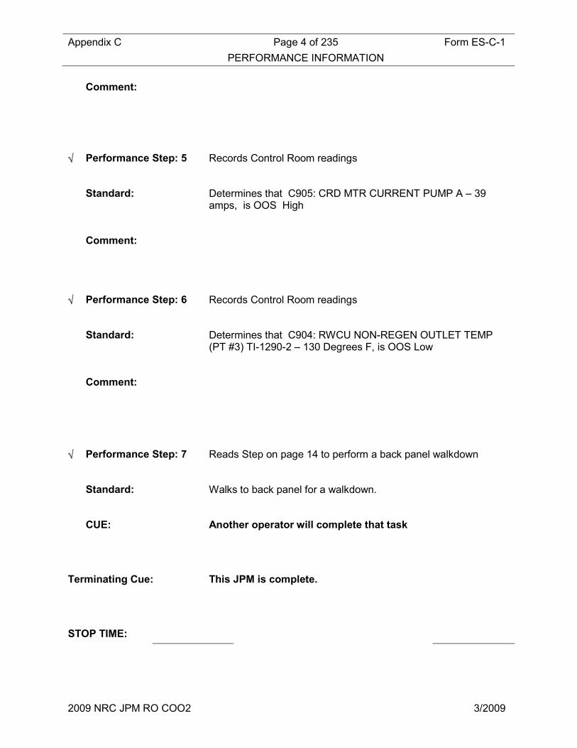
Comment:
√ Performance Step: 5 Records Control Room readings
Standard: Determines that C905: CRD MTR CURRENT PUMP A – 39 amps, is OOS High
Comment:
√ Performance Step: 6 Records Control Room readings
Standard: Determines that C904: RWCU NON-REGEN OUTLET TEMP (PT #3) TI-1290-2 – 130 Degrees F, is OOS Low
Comment:
√ Performance Step: 7 Reads Step on page 14 to perform a back panel walkdown
Standard: Walks to back panel for a walkdown.
CUE: Another operator will complete that task
Terminating Cue: This JPM is complete.
STOP TIME:

Appendix C Page 5 of 235 Form ES-C-1
VERIFICATION OF COMPLETION
2009 NRC JPM RO COO2 3/2009
Job Performance Measure No.: 2009 NRC JPM RO COO2
Examinee’s Name:
Date Performed:
Facility Evaluator:
Number of Attempts:
Time to Complete:
Question Documentation:
Question:
Response:
Result: SAT UNSAT
Examiner’s Signature: Date:
Appendix C Job Performance Measure Form ES-C-1
Worksheet
2009 NRC JPM RO EC 3/2009
INITIAL CONDITIONS: The plant is operating at 100% power.
INITIATING CUE: You are directed to complete the 0800 – 1200 control room readings IAW PNPS 2.1.35 Att.2.
Facility: PILGRIM Task No.:
Task Title: Recirc Pump Speed & Jet Pump Operability Surveillance Check
JPM No.: 2009 NRC RO JPM EC
K/A Reference: 2.2.12 3.7
Examinee: NRC Examiner:
Facility Evaluator: Date:
Method of testing:
Simulated Performance: Actual Performance: X
Classroom Simulator X Plant
READ TO THE EXAMINEE
I will explain the initial conditions, which steps to simulate or discuss, and provide initiating cues. When you complete the task successfully, the objective for this Job Performance Measure will be satisfied.
Initial Conditions: The plant is operating at 90% power following a reactor plant startup 2 days ago. Daily Log Tests 17 & 17A have not yet been completed.

Appendix C Job Performance Measure Form ES-C-1
Worksheet
2009 NRC JPM RO EC 3/2009
Task Standard: Determines that
Required Materials: N/A
General References: PNPS 2.1.15 Daily Log Test 17 & 17A
Initiating Cue: You are directed to perform PNPS 2.1.15 Daily Log Test 17 & 17A for Recirc Pump Speed and Jet Pump Operability and determine if acceptance criteria is met.
Time Critical Task: NO
Validation Time: 15 minutes
Appendix C Job Performance Measure Form ES-C-1
Worksheet
2009 NRC JPM RO EC 3/2009
SIMULATOR SETUP
1. Initialize simulator to IC14 2. Insert Malfunction RR19, Jet Pump Riser Failure 3. Allow Simulator to stabilize 4. Verify Epic is operating
Appendix C Page 9 of 235 Form ES-C-1
PERFORMANCE INFORMATION
2009 NRC JPM RO EC 3/2009
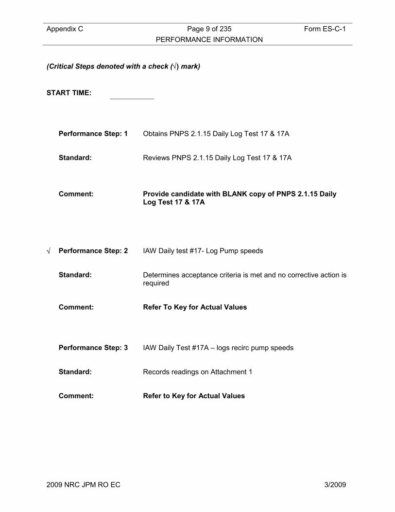
(Critical Steps denoted with a check (√) mark)
START TIME:
Performance Step: 1 Obtains PNPS 2.1.15 Daily Log Test 17 & 17A
Standard: Reviews PNPS 2.1.15 Daily Log Test 17 & 17A
Comment: Provide candidate with BLANK copy of PNPS 2.1.15 Daily Log Test 17 & 17A
√ Performance Step: 2 IAW Daily test #17- Log Pump speeds
Standard: Determines acceptance criteria is met and no corrective action is required
Comment: Refer To Key for Actual Values
Performance Step: 3 IAW Daily Test #17A – logs recirc pump speeds
Standard: Records readings on Attachment 1
Comment: Refer to Key for Actual Values

Appendix C Page 10 of 235 Form ES-C-1
PERFORMANCE INFORMATION
2009 NRC JPM RO EC 3/2009
√ Performance Step: 4 IAW Daily Test #17A – records recirc loop flows. Determines if Recirc Pump Loop Flows are within predicted limits of Table 17A.
Standard: Records readings and, using tables, determines that recirc pump loop flow is within the predicted limits for the current recirc pump speed.
Comment: Refer to Key for Actual Values
√ Performance Step: 5 IAW Daily Test #17A – records actual Jet Pump loop flows. Determines if Jet Pump Loop Flows are within predicted limits of Table 17A.
Standard: Records readings and, using tables, determines that Jet Pump loop flow is outside the predicted limits for the current recirc pump speed.
Comment: Refer to Key for Actual Values
√ Performance Step: 6 Reviews previous steps to determine overall status of test.
Standard: Determines that the Jet Pump Loop Flow too Speed Ratio differs by >5% and marks Step #7(b) as FAILED
Reports results to CRS (evaluator)
Comment: Refer to Key for Actual Values
Terminating Cue: This JPM is complete.
STOP TIME:
Appendix C Page 11 of 235 Form ES-C-1
VERIFICATION OF COMPLETION
2009 NRC JPM RO EC 3/2009
Job Performance Measure No.: 2009 NRC JPM RO EC
Examinee’s Name:
Date Performed:
Facility Evaluator:
Number of Attempts:
Time to Complete:
Question Documentation:
Question:
Response:
Result: SAT UNSAT
Examiner’s Signature: Date:
Appendix C Job Performance Measure Form ES-C-1
Worksheet
2009 NRC JPM RO RC 2/2009
INITIAL CONDITIONS: The plant is operating at 90% power following a reactor plant startup 2 days ago. Daily Log Tests 17 & 17A have not yet been completed.
INITIATING CUE: You are directed to perform PNPS 2.1.15 Daily Log Test 17 & 17A for Recirc Pump Speed and Jet Pump Operability and determine if acceptance criteria is met.
Appendix C Job Performance Measure Form ES-C-1
Worksheet
2009 NRC JPM RO RC 2/2009
Facility: PILGRIM Task No.: NEW
Task Title: Determine Offsite Release Rate IAW PNPS 2.1.15 Daily Log Test #34.
JPM No.: 2009 NRC JPM RO RC
K/A Reference: K/A: 2.3.11 (3.8)
Ability to control radiation releases.
Examinee: NRC Examiner:
Facility Evaluator: Date:
Method of testing:
Simulated Performance: Actual Performance: X
Classroom Simulator X Plant
READ TO THE EXAMINEE
I will explain the initial conditions, which steps to simulate or discuss, and provide initiating cues. When you complete the task successfully, the objective for this Job Performance Measure will be satisfied.
Initial Conditions: Plant conditions are as follows:
• The plant is at power with indications of as fuel element failure present.
• A plant shutdown is in progress.
Task Standard:
Completes daily Log Test #34 and determines that an ODCM limit has been exceeded and informs CRS.
Note:
Required Materials: PNPS 2.1.15 Att.2 Page 109 of 150
General References: PNPS 2.1.15 Att.2
Initiating Cue: You are directed to determine Offsite Release Rate IAW PNPS 2.1.15 Daily Log Test #34

Appendix C Job Performance Measure Form ES-C-1
Worksheet
2009 NRC JPM RO RC 2/2009
Time Critical Task: NO
Validation Time: 15 minutes

Appendix C Job Performance Measure Form ES-C-1
Worksheet
2009 NRC JPM RO RC 2/2009
SIMULATOR SETUP
1. Using detector failure malfunctions:
a. Set Rx Bld Vent Rad Monitor 32A to 608 b. Set Rx Bld Vent Rad Monitor 32B to 589 c. Set Main Stack Rad Monitor 18A to 6095 d. Set Main Stack Rad Monitor 18B to 5988
2. Verify EPIC is operating and that:
a. Main Stack release rate is ~ 36,000 uCI/sec b. Reactor Building release rate is ~ 4000 uCi/sec
3. Note: it will take ~ 2 minutes for EPIC readings to stabilize.
Appendix C Page 16 of 235 Form ES-C-1
PERFORMANCE INFORMATION
2009 NRC JPM RO RC 2/2009
(Denote Critical Steps with a check mark)
START TIME:
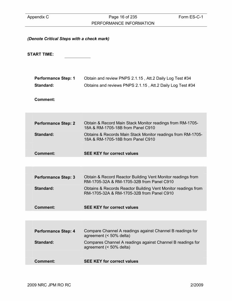
Performance Step: 1 Obtain and review PNPS 2.1.15 , Att.2 Daily Log Test #34
Standard: Obtains and reviews PNPS 2.1.15 , Att.2 Daily Log Test #34
Comment:
Performance Step: 2 Obtain & Record Main Stack Monitor readings from RM-1705-18A & RM-1705-18B from Panel C910
Standard: Obtains & Records Main Stack Monitor readings from RM-1705-18A & RM-1705-18B from Panel C910
Comment: SEE KEY for correct values
Performance Step: 3 Obtain & Record Reactor Building Vent Monitor readings from RM-1705-32A & RM-1705-32B from Panel C910
Standard: Obtains & Records Reactor Building Vent Monitor readings from RM-1705-32A & RM-1705-32B from Panel C910
Comment: SEE KEY for correct values
Performance Step: 4 Compare Channel A readings against Channel B readings for agreement (< 50% delta)
Standard: Compares Channel A readings against Channel B readings for agreement (< 50% delta)
Comment: SEE KEY for correct values
Appendix C Page 17 of 235 Form ES-C-1
PERFORMANCE INFORMATION
2009 NRC JPM RO RC 2/2009
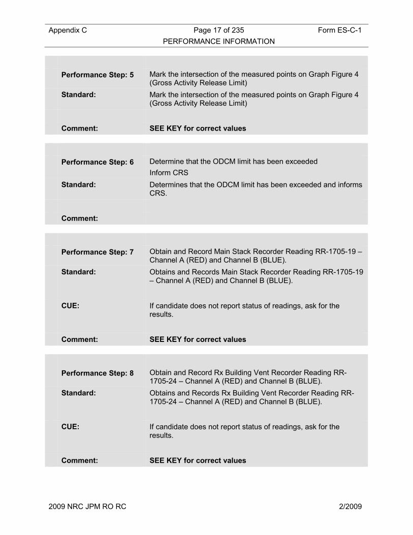
Performance Step: 5 Mark the intersection of the measured points on Graph Figure 4 (Gross Activity Release Limit)
Standard: Mark the intersection of the measured points on Graph Figure 4 (Gross Activity Release Limit)
Comment: SEE KEY for correct values
Performance Step: 6 Determine that the ODCM limit has been exceeded
Inform CRS
Standard: Determines that the ODCM limit has been exceeded and informs CRS.
Comment:
Performance Step: 7 Obtain and Record Main Stack Recorder Reading RR-1705-19 – Channel A (RED) and Channel B (BLUE).
Standard: Obtains and Records Main Stack Recorder Reading RR-1705-19 – Channel A (RED) and Channel B (BLUE).
CUE: If candidate does not report status of readings, ask for the results.
Comment: SEE KEY for correct values
Performance Step: 8 Obtain and Record Rx Building Vent Recorder Reading RR-1705-24 – Channel A (RED) and Channel B (BLUE).
Standard: Obtains and Records Rx Building Vent Recorder Reading RR-1705-24 – Channel A (RED) and Channel B (BLUE).
CUE: If candidate does not report status of readings, ask for the results.
Comment: SEE KEY for correct values
Appendix C Page 18 of 235 Form ES-C-1
PERFORMANCE INFORMATION
2009 NRC JPM RO RC 2/2009
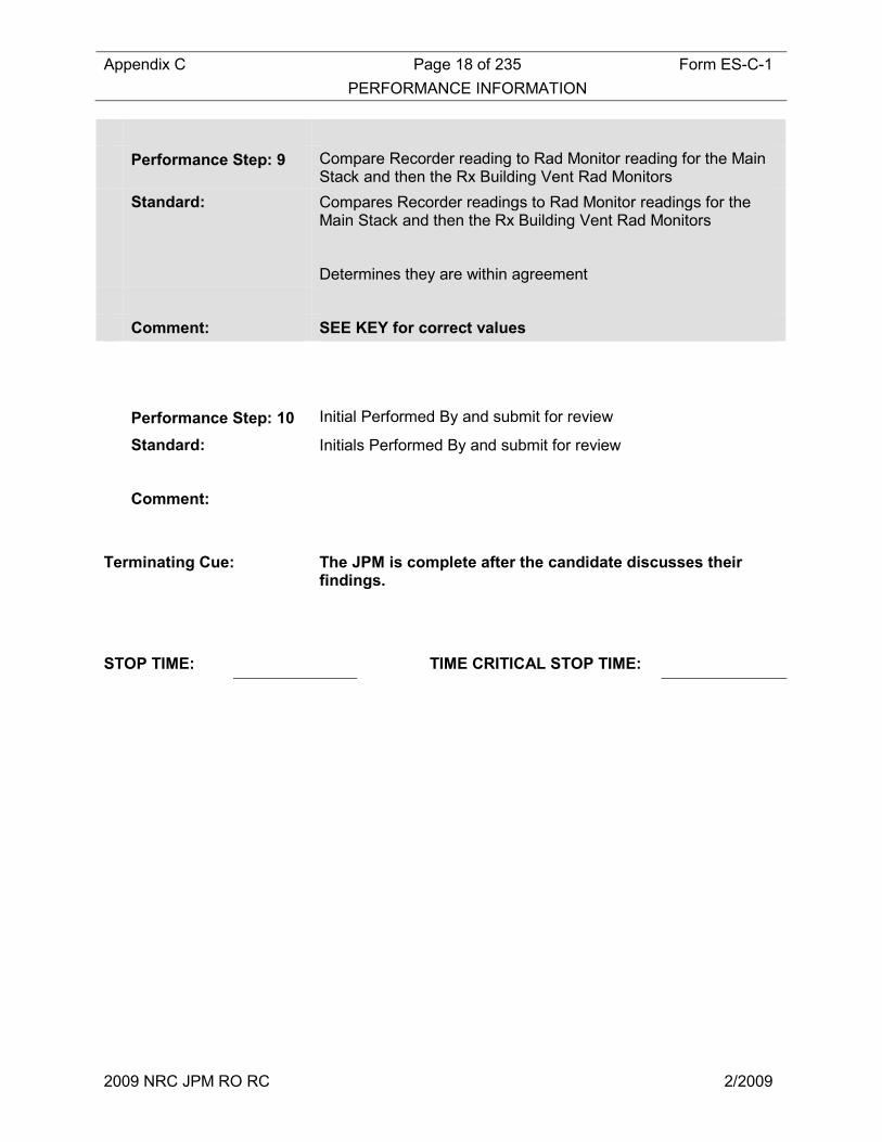
Performance Step: 9 Compare Recorder reading to Rad Monitor reading for the Main Stack and then the Rx Building Vent Rad Monitors
Standard: Compares Recorder readings to Rad Monitor readings for the Main Stack and then the Rx Building Vent Rad Monitors
Determines they are within agreement
Comment: SEE KEY for correct values
Performance Step: 10 Initial Performed By and submit for review
Standard: Initials Performed By and submit for review
Comment:
Terminating Cue: The JPM is complete after the candidate discusses their findings.
STOP TIME: TIME CRITICAL STOP TIME:

Appendix C Page 19 of 235 Form ES-C-1
VERIFICATION OF COMPLETION
2009 NRC JPM RO RC 2/2009
Job Performance Measure No.: 2009 AUDIT JPM RO RC
Examinee’s Name:
Date Performed:
Facility Evaluator:
Number of Attempts:
Time to Complete:
Question Documentation:
Question:
Response:
Result: SAT UNSAT
Examiner’s Signature: Date:

Appendix C Job Performance Measure Form ES-C-1
Worksheet
2009 NRC JPM RO/SRO COO1 3/2009
Initial Conditions: Plant conditions are as follows:
• The plant is at power with indications of as fuel element failure present.
• A plant shutdown is in progress. Initiating Cue: You are directed to determine Offsite Release Rate IAW PNPS 2.1.15
Daily Log Test #34
Appendix C Job Performance Measure Form ES-C-1
Worksheet
2009 NRC JPM RO/SRO COO1 3/2009
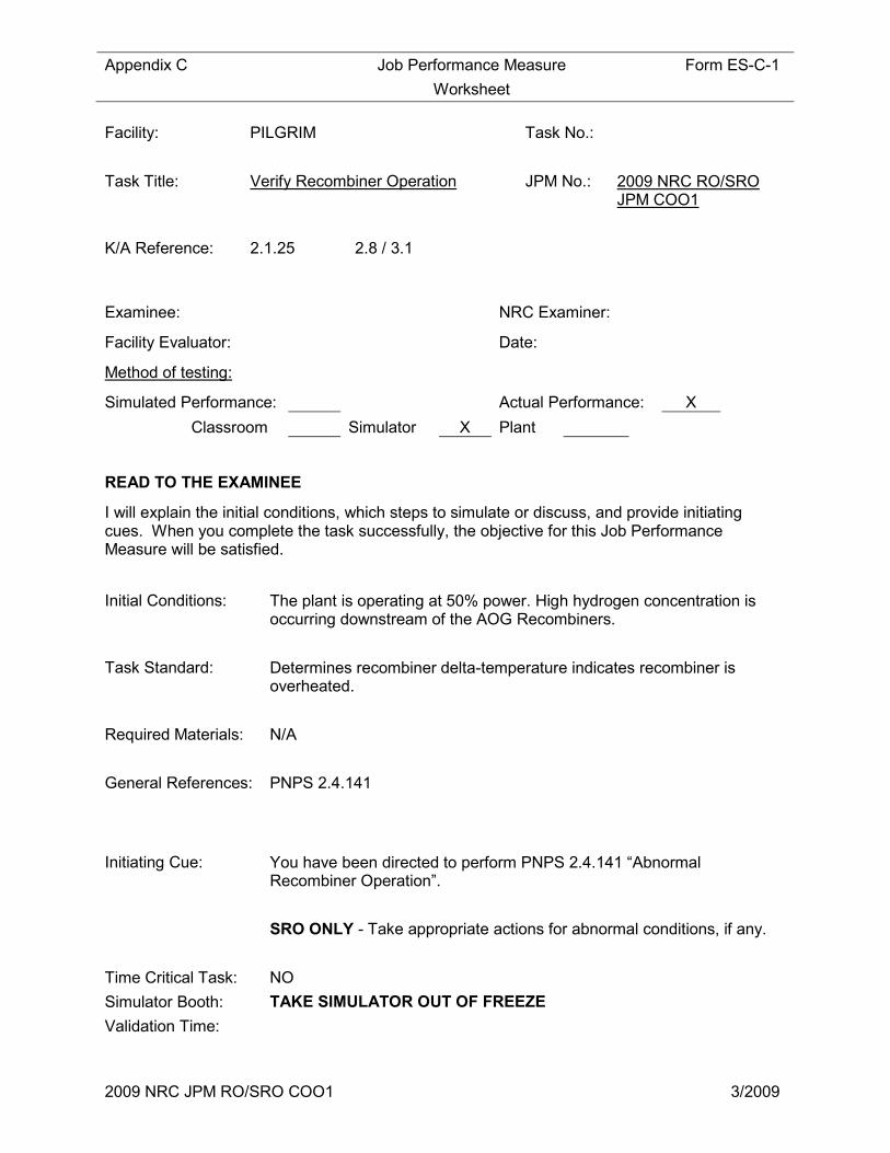
Facility: PILGRIM Task No.:
Task Title: Verify Recombiner Operation JPM No.: 2009 NRC RO/SRO JPM COO1
K/A Reference: 2.1.25 2.8 / 3.1
Examinee: NRC Examiner:
Facility Evaluator: Date:
Method of testing:
Simulated Performance: Actual Performance: X
Classroom Simulator X Plant
READ TO THE EXAMINEE
I will explain the initial conditions, which steps to simulate or discuss, and provide initiating cues. When you complete the task successfully, the objective for this Job Performance Measure will be satisfied.
Initial Conditions: The plant is operating at 50% power. High hydrogen concentration is occurring downstream of the AOG Recombiners.
Task Standard: Determines recombiner delta-temperature indicates recombiner is overheated.
Required Materials: N/A
General References: PNPS 2.4.141
Initiating Cue: You have been directed to perform PNPS 2.4.141 “Abnormal Recombiner Operation”.
SRO ONLY - Take appropriate actions for abnormal conditions, if any.
Time Critical Task: NO
Simulator Booth: TAKE SIMULATOR OUT OF FREEZE
Validation Time:
Appendix C Job Performance Measure Form ES-C-1
Worksheet
2009 NRC JPM RO/SRO COO1 3/2009
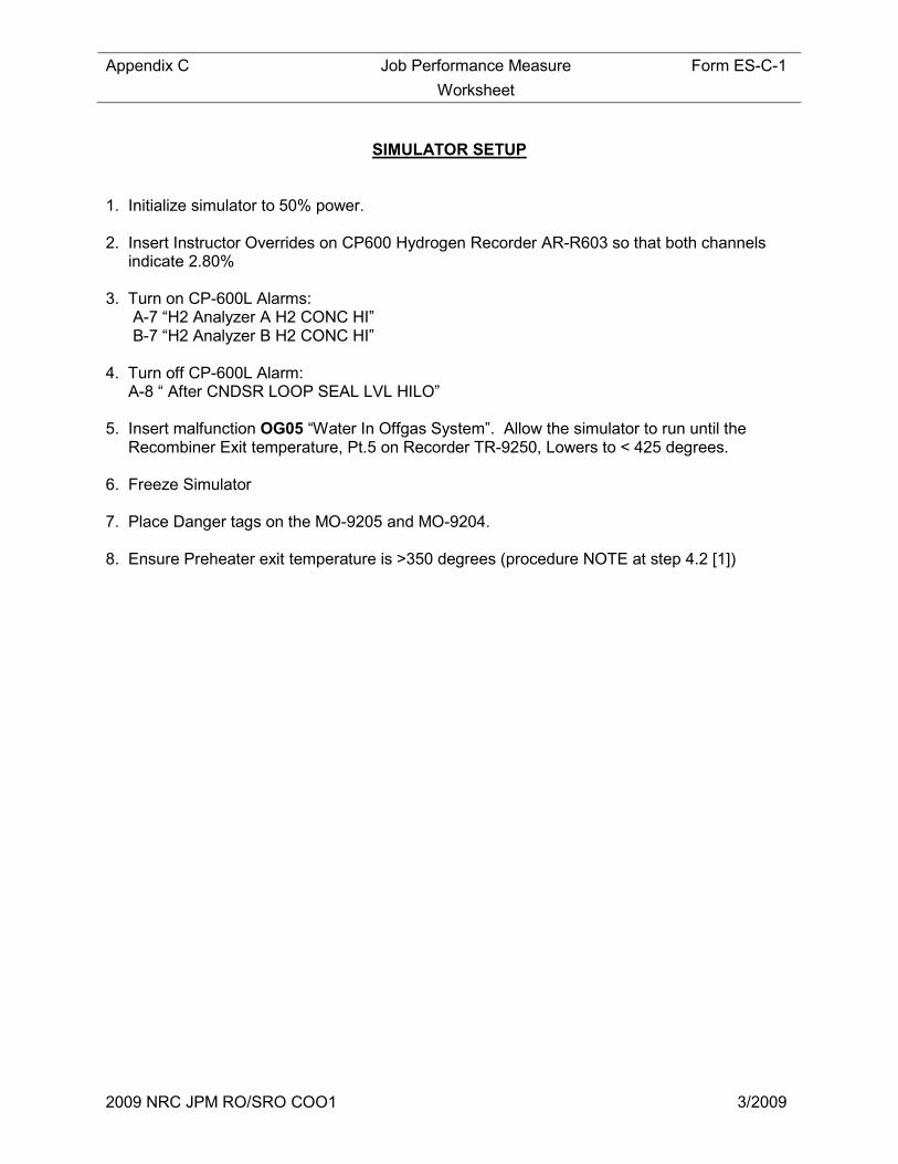
SIMULATOR SETUP
1. Initialize simulator to 50% power. 2. Insert Instructor Overrides on CP600 Hydrogen Recorder AR-R603 so that both channels indicate 2.80% 3. Turn on CP-600L Alarms: A-7 “H2 Analyzer A H2 CONC HI” B-7 “H2 Analyzer B H2 CONC HI” 4. Turn off CP-600L Alarm: A-8 “ After CNDSR LOOP SEAL LVL HILO” 5. Insert malfunction OG05 “Water In Offgas System”. Allow the simulator to run until the Recombiner Exit temperature, Pt.5 on Recorder TR-9250, Lowers to < 425 degrees. 6. Freeze Simulator 7. Place Danger tags on the MO-9205 and MO-9204. 8. Ensure Preheater exit temperature is >350 degrees (procedure NOTE at step 4.2 [1])

Appendix C Page 23 of 235 Form ES-C-1
PERFORMANCE INFORMATION
2009 NRC JPM RO/SRO COO1 3/2009
(Critical Steps denoted with a check (√) mark)
START TIME:
Performance Step: 1 Section 3.0 – If the recombiner temperature exceeds 1000 degrees F AND a reactor scram has not been initiated, THEN SCRAM the reactor AND ENTER PNPS 2.1.6, “Reactor Scram”.
Standard: Determines that temperature has not exceeded 1000 degrees and a reactor scram is not required.
Comment: Recombiner temperature can be determined at point 5 on recorder TR-9250.
Performance Step: 2 Proceeds to PNPS 2.4.141 Section 4.2 - High Hydrogen Concentration Downstream of the Recombiners.
Standard: Enters PNPS 2.4.141 Section 4.2
Comment:
√ Performance Step: 3 Section 4.2 Step [1] - TRIP the ETS using "ETS SHUTDOWN" push button on Panel CP600.
Standard: Depresses "ETS SHUTDOWN" pushbutton
Comment:
SIM BOOTH: Ensure Preheater exit temperature is >350 degrees

Appendix C Page 24 of 235 Form ES-C-1
PERFORMANCE INFORMATION
2009 NRC JPM RO/SRO COO1 3/2009
Performance Step: 4 Section 4.2 Step [2] - If both H2 analyzers are indicating greater than or equal to 4%....
Standard: Reviews above NOTE.
Determines that both H2 analyzers are not greater than 4% and continues in procedure
Comment:
√ Performance Step: 5 Section 4.2 [3] - Verify recombiner operation for the power level being maintained by referring to Att. 1 or Att. 2 as applicable.
Standard: Evaluates recombiner delta-temperature utilizing Att. 1 and determines recombiner delta-temperature is in the questionable region of the graph.
Reports results to CRS (examiner)
Evaluator Note: For Att.1, Recombiner ∆T is determined by subtracting Preheater Exit Temperature (Indicator TI-R601A) from Recombiner TOP Temperature (Point 5 on Recorder TR-9250). Reactor power is provided in the initiating cue.
This will result in a point residing in the questionable region of the graph.
Comment: NOTE The procedure step states to use Att.1 OR Att.2. Prompt candidate to evaluate using both graphs if only one is used.
Appendix C Page 25 of 235 Form ES-C-1
PERFORMANCE INFORMATION
2009 NRC JPM RO/SRO COO1 3/2009
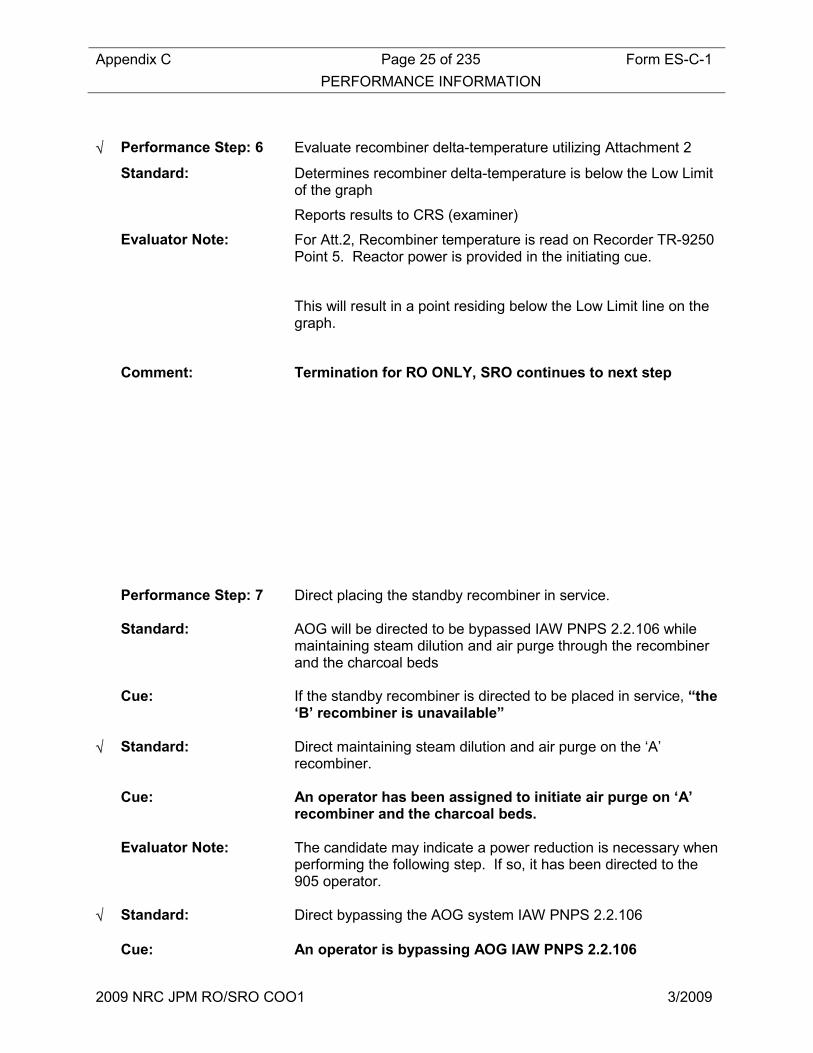
√ Performance Step: 6 Evaluate recombiner delta-temperature utilizing Attachment 2
Standard: Determines recombiner delta-temperature is below the Low Limit of the graph
Reports results to CRS (examiner)
Evaluator Note: For Att.2, Recombiner temperature is read on Recorder TR-9250 Point 5. Reactor power is provided in the initiating cue.
This will result in a point residing below the Low Limit line on the graph.
Comment: Termination for RO ONLY, SRO continues to next step
Performance Step: 7 Direct placing the standby recombiner in service. Standard: AOG will be directed to be bypassed IAW PNPS 2.2.106 while
maintaining steam dilution and air purge through the recombiner and the charcoal beds
Cue: If the standby recombiner is directed to be placed in service, “the
‘B’ recombiner is unavailable” √ Standard: Direct maintaining steam dilution and air purge on the ‘A’
recombiner. Cue: An operator has been assigned to initiate air purge on ‘A’
recombiner and the charcoal beds. Evaluator Note: The candidate may indicate a power reduction is necessary when
performing the following step. If so, it has been directed to the 905 operator.
√ Standard: Direct bypassing the AOG system IAW PNPS 2.2.106 Cue: An operator is bypassing AOG IAW PNPS 2.2.106
Appendix C Page 26 of 235 Form ES-C-1
PERFORMANCE INFORMATION
2009 NRC JPM RO/SRO COO1 3/2009
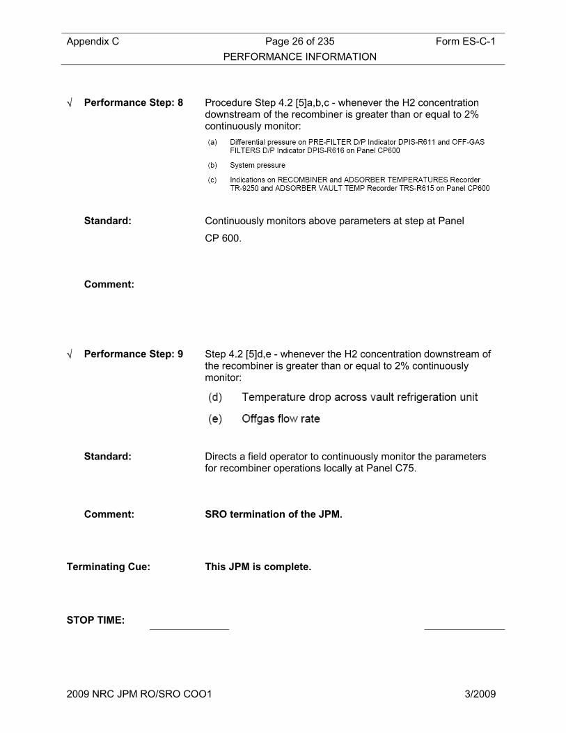
√ Performance Step: 8 Procedure Step 4.2 [5]a,b,c - whenever the H2 concentration downstream of the recombiner is greater than or equal to 2% continuously monitor:
Standard: Continuously monitors above parameters at step at Panel
CP 600.
Comment:
√ Performance Step: 9 Step 4.2 [5]d,e - whenever the H2 concentration downstream of the recombiner is greater than or equal to 2% continuously monitor:
Standard: Directs a field operator to continuously monitor the parameters for recombiner operations locally at Panel C75.
Comment: SRO termination of the JPM.
Terminating Cue: This JPM is complete.
STOP TIME:

Appendix C Page 27 of 235 Form ES-C-1
VERIFICATION OF COMPLETION
2009 NRC JPM RO/SRO COO1 3/2009
Job Performance Measure No.: 2009 NRC JPM RO/SRO COO1
Examinee’s Name:
Date Performed:
Facility Evaluator:
Number of Attempts:
Time to Complete:
Question Documentation:
Question:
Response:
Result: SAT UNSAT
Examiner’s Signature: Date:

Appendix C Job Performance Measure Form ES-C-1
Worksheet
2009 NRC JPM SRO COO2 3/2009
INITIAL CONDITIONS: The plant is operating at 50% power. High hydrogen concentration is occurring downstream of the AOG Recombiners.
INITIATING CUE: You have been directed to perform PNPS 2.4.141 “Abnormal Recombiner Operation”.
SRO ONLY - Take appropriate actions for abnormal conditions, if any.

Appendix C Job Performance Measure Form ES-C-1
Worksheet
2009 NRC JPM SRO COO2 3/2009
Facility: PILGRIM Task No.:
Task Title: Perform & Assess requirements for a Recirc Pump Start
JPM No.: 2009 NRC SRO JPM COO2
K/A Reference: 2.1.7 4.7
Examinee: NRC Examiner:
Facility Evaluator: Date:
Method of testing:
Simulated Performance: Actual Performance: X
Classroom Simulator X Plant
READ TO THE EXAMINEE
I will explain the initial conditions, which steps to simulate or discuss, and provide initiating cues. When you complete the task successfully, the objective for this Job Performance Measure will be satisfied.
Initial Conditions: “B” Recirc MG Set tripped 2 days ago and single loop operations were commenced.
The Recirc MG Set fault has been repaired and preparations are underway to restart the “B” Recirc MG set IAW Section 7.4 of 2.2.84 “Reactor Recirculation System”.
EPIC is not available.
Task Standard: Determines that TS limitations have been eclipsed and are not satisfied at this time to permit a pump start.
Required Materials: N/A
General References: PNPS
Initiating Cue: You are directed to perform PNPS 2.2.84 Att [5] Section B for temperature limits in preparation for the start of “B” Recirc Pump.
Time Critical Task: NO
Appendix C Job Performance Measure Form ES-C-1
Worksheet
2009 NRC JPM SRO COO2 3/2009
Validation Time: 15 minutes

Appendix C Job Performance Measure Form ES-C-1
Worksheet
2009 NRC JPM SRO COO2 3/2009
SIMULATOR SETUP
1. Initialize simulator to IC12 2. Trip “B” Recirc pump manually and close the discharge valve 3. Manipulate “A” Recirc & Rods such that:
• Core Flow is between 27.6 and 36 mlbm/hr • Core Operating Point is outside of the Buffer Region
4. Insert Instructor Overrides such that:
• “B” Recirc Loop suction temp is 65 degrees less than the “A” Recirc Loop suction temp as indicated on TR-260-151 A/B
• Vessel Bottom head drain temp (Pt.3 on TR-263-104) is 170 degrees below current vessel saturation temperature
5. Shutdown EPIC using remote function 6. Ensure that operating recirc pump speed is <50% 6. Freeze the simulator

Appendix C Page 32 of 235 Form ES-C-1
PERFORMANCE INFORMATION
2009 NRC JPM SRO COO2 3/2009
START TIME:
Performance Step: 1 Obtains PNPS 2.2.84, Att.5
Standard: Reviews Limitations of PNPS 2.2.84, Att.5
Comment: Provide candidate with blank copy of PNPS 2.2.84
Attachment 5 Steps
√ Performance Step: 2
Standard: Records data & determines that limitations of Step B. [1](a) are NOT met.
Per Procedure Note:
References PNPS 2.4.24, Att.1 Step 3, and directs raising Bottom Head Flow to RWCU.
CUE: After the candidate informs you of the requirements of 2.4.24 and directs raising flow, then state that another operator will perform that task and they should continue with this attachment
Comment: Bottom Head drain temperature will be approximately 170 degrees below current vessel saturation temperature
Appendix C Page 33 of 235 Form ES-C-1
PERFORMANCE INFORMATION
2009 NRC JPM SRO COO2 3/2009
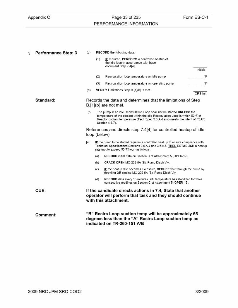
√ Performance Step: 3
Standard: Records the data and determines that the limitations of Step B.[1](b) are not met.
References and directs step 7.4[4] for controlled heatup of idle loop (below)
CUE: If the candidate directs actions in 7.4, State that another operator will perform that task and they should continue with this attachment.
Comment: “B” Recirc Loop suction temp will be approximately 65degrees less than the “A” Recirc Loop suction temp as indicated on TR-260-151 A/B

Appendix C Page 34 of 235 Form ES-C-1
PERFORMANCE INFORMATION
2009 NRC JPM SRO COO2 3/2009
√ Performance Step: 4
Standard: Verifies that operating pump speed is < 50%
Comment: See key for actual values
Terminating Cue: This JPM is complete.
STOP TIME:

Appendix C Page 35 of 235 Form ES-C-1
VERIFICATION OF COMPLETION
2009 NRC JPM SRO COO2 3/2009
Job Performance Measure No.: 2009 NRC JPM SRO COO2
Examinee’s Name:
Date Performed:
Facility Evaluator:
Number of Attempts:
Time to Complete:
Question Documentation:
Question:
Response:
Result: SAT UNSAT
Examiner’s Signature: Date:
Appendix C Page 36 of 235 Form ES-C-1
PERFORMANCE INFORMATION
2009 NRC JPM SRO COO2 3/2009
INITIAL CONDITIONS: “B” Recirc MG Set tripped 2 days ago and single loop operations were commenced.
The Recirc MG Set fault has been repaired and preparations are underway to restart the “B” Recirc MG set IAW Section 7.4 of 2.2.84 “Reactor Recirculation System”.
EPIC is not available.
INITIATING CUE: You are directed to perform PNPS 2.2.84 Att [5] Section B for temperature limits in preparation for the start of “B” Recirc Pump.
Appendix C Page 37 of 235 Form ES-C-1
PERFORMANCE INFORMATION
2009 NRC JPM SRO COO2 3/2009
Facility: PILGRIM Task No.:
Task Title: Review RBCCW Pump “A” System Quarterly Operability PNPS 8.5.3.1 – Determine pump operability
JPM No.: 2009 NRC SRO JPM EC
K/A Reference: 2.2.12 4.1
Examinee: NRC Examiner:
Facility Evaluator: Date:
Method of testing:
Simulated Performance: Actual Performance: X
Classroom X Simulator Plant
READ TO THE EXAMINEE
I will explain the initial conditions, which steps to simulate or discuss, and provide initiating cues. When you complete the task successfully, the objective for this Job Performance Measure will be satisfied.
Initial Conditions: The RBCCW Pump “A” System Quarterly Operability Test - PNPS 8.5.3.1 – has been completed.
All RBCCW System components are operable.
Task Standard: Identify that the pump is inoperable due to not meeting acceptance criteria.
Required Materials: N/A
General References: PNPS
Initiating Cue: Review the RBCCW Pump “A” System Quarterly Operability Test - PNPS 8.5.3.1 – Review Acceptance Criteria and determine pump operability.
Time Critical Task: NO

Appendix C Page 38 of 235 Form ES-C-1
PERFORMANCE INFORMATION
2009 NRC JPM SRO COO2 3/2009
Validation Time: 15 minutes
Appendix C Page 39 of 235 Form ES-C-1
PERFORMANCE INFORMATION
2009 NRC JPM SRO COO2 3/2009
SIMULATOR SETUP
N/A (Critical Steps denoted with a check (√) mark)
START TIME:
Performance Step: 1 Obtain RBCCW Pump “A” System Quarterly Operability Test - PNPS 8.5.3.1 Att.1A
Standard: Obtains RBCCW Pump “A” System Quarterly Operability Test - PNPS 8.5.3.1 Att.1A
Comment: Provide completed surveillance to candidate.

Appendix C Page 40 of 235 Form ES-C-1
PERFORMANCE INFORMATION
2009 NRC JPM SRO COO2 3/2009
√ Performance Step: 2 Reviews Acceptance Criteria
Standard: 1. Determines that Total Dynamic Head Calculation is incorrect.
2. The correct calculation puts you in the Required Action Range.
3. Determines pump is inoperable
** May reference TS 3.5.B.3 Action A.1. – 7 days, However, this TS does not apply because 2 other RBCCW pumps are operable in the loop (at least 2 required).
Comment: Items 1, 2 and 3 are Critical Steps – See Key
√ Performance Step: 3 Reviews Acceptance Criteria
Standard: 4. Determines Pump Inboard Vertical Vibration is in the Alert
Range
Comment: Item is a Critical Step
Appendix C Page 41 of 235 Form ES-C-1
PERFORMANCE INFORMATION
2009 NRC JPM SRO COO2 3/2009
Terminating Cue: This JPM is complete.
STOP TIME:

Appendix C Page 42 of 235 Form ES-C-1
VERIFICATION OF COMPLETION
2009 NRC JPM SRO COO2 3/2009
Job Performance Measure No.: 2009 NRC JPM SRO EC
Examinee’s Name:
Date Performed:
Facility Evaluator:
Number of Attempts:
Time to Complete:
Question Documentation:
Question:
Response:
Result: SAT UNSAT
Examiner’s Signature: Date:

Appendix C Job Performance Measure Form ES-C-1
Worksheet
2009 NRC JPM SRO RC 2/2009
INITIAL CONDITIONS: The RBCCW Pump “A” System Quarterly Operability Test - PNPS 8.5.3.1 – has been completed.
All RBCCW System components are operable.
INITIATING CUE: Review the RBCCW Pump “A” System Quarterly Operability Test - PNPS 8.5.3.1 – Review Acceptance Criteria and determine pump operability.

Appendix C Job Performance Measure Form ES-C-1
Worksheet
2009 NRC JPM SRO RC 2/2009
NUCLEAR PLANT OPERATOR JOB PERFORMANCE MEASURE
(SRO Only) TITLE: EMERGENCY PLAN IMPLEMENTATION
OPERATOR:
DATE:
EVALUATOR:
EVALUATOR SIGNATURE:
CRITICAL TIME FRAME #1:
(Assessment and Declaration)
Required Time (min): 15 Actual Time (min):
CRITICAL TIME FRAME #2:
(Notification of Off-Site Agencies)
Required Time (min): 15 Actual Time (min):
PERFORMANCE TIME: Average Time (min): 20 Actual Time (min):
JPM RESULTS*: (Circle one) *Refer to Grading Instructions at end of JPM
SAT UNSAT NEEDS IMPROVEMENT
SYNOPSIS:
The SRO will assess plant conditions using the information provided, compare plant conditions against the Emergency Action Level (EAL) criteria and declare the appropriate EAL. Following the initial declaration, the SRO will activate the PNPS Emergency Response Organization (ERO) and complete the notification of off-site agencies.
TASK STANDARD:
The SRO will declare an Alert based on EAL 7.3.1.2, Aircraft crash on the facility affecting plant operation, within 15 minutes. Following initial declaration the SRO will activate the PNPS ERO and complete the notification of off-site agencies in accordance with EP-IP-100. Notification of off-site agencies shall be completed within 15 minutes of initial declaration.
EVALUATION METHOD: EVALUATION LOCATION:
x Perform Plant
Simulate x Simulator
Control Room
Prepared: Date:
Reviewed: Date:
Approved: Superintendent, Operations Training (or Designee)
Date:
Appendix C Job Performance Measure Form ES-C-1
Worksheet
2009 NRC JPM SRO RC 2/2009
REVISION LOG Revision Number: 0 Date Originated: 11/20/2008
Pages Affected: All Description: New JPM

Appendix C Job Performance Measure Form ES-C-1
Worksheet
2009 NRC JPM SRO RC 2/2009
TASK Title: Task Number K&A SYSTEM: K&A RATING:
Classify events requiring Emergency Plan implementation.
015-05-02-013 Generic 2.4.40 2.7 / 4.5
REFERENCES: EP-IP-100 Emergency Classification and Notification SIMULATOR CONDITIONS: 1. The simulator may be initialized to any IC. 2. Using remote function MT22, set outside weather conditions to:
a) Wind direction on 220 foot met tower: 264 degrees b) Wind speed on 220 foot met tower: 13 mph
3. Allow simulator to run a sufficient amount of time to allow the 15 minute averages on the met tower display to stabilize.
4. The Digital Notification System is Operable and in the Training Configuration. GENERAL TOOLS AND EQUIPMENT: 1. None CRITICAL ELEMENTS: Critical elements are shaded in gray within the body of this document. OPERATOR BRIEF:
1. State the following paragraph IF this is the first performance in this setting:
a) “All actions associated with this job performance measure are to be performed. You will be provided access to any tools or equipment you determine necessary to perform the task. When a second checker is called for, the evaluator will perform the role of second checker and will always be in agreement with your actions. Before you start, the evaluator will state the task conditions and answer any questions, then provide a cue to begin”.

Appendix C Job Performance Measure Form ES-C-1
Worksheet
2009 NRC JPM SRO RC 2/2009
INITIAL CONDITIONS:
1) PNPS was at full power when a load reject and loss of off-site power occurred.
2) All control rods fully inserted.
3) Both Emergency Diesel Generators Started and 4160 VAC buses A5 and A6 have been re-energized. All other 4160 VAC buses have de-energized.
4) The security shift commander has called the control room and reported that a small aircraft crashed into the switchyard and that three 345 KV ACBs have been severely damaged. The aircraft is on fire and off-site fire fighting assistance is recommended. No PNPS equipment is currently engulfed by the fire.
5) Following the scram, RPV Level lowered to - 47 inches. Both RCIC and HPCI auto started and aligned for injection.
6) HPCI was manually shifted to pressure control when RPV level recovered to the normal band.
7) RPV level is currently stable at 20 inches being controlled by RCIC
8) RPV pressure is currently 900 psig and slowly lowering with HPCI in pressure control.
9) The Control Room Supervisor is coordinating overall plant response, including fire brigade response and notification of Plymouth Fire.
10) All containment parameters are normal, with the exception of Torus Water Temperature. Torus Water Temperature has just exceeded 80 degrees.
11) The security shift commander has determined that this is not a security event and that plant access and egress has not been impacted.
12) Weather conditions are as indicated on Panel MT1
INITIATING CUE: You are the Third SRO on shift. The Shift Manager is incapacitated. Implement the Emergency Plan as required.

Appendix C Job Performance Measure Form ES-C-1
Worksheet
2009 NRC JPM SRO RC 2/2009
PERFORMANCE:
Notes This task is covered in EP-IP 100, Emergency Classification and Notification. Notification of Off-site Agencies will be completed via the Digital Notification Network.
Attachment 2 of this JPM contains the anticipated information to be entered for the initial notification to off-site agencies and may be used as an aid in evaluating the accuracy of the initial notification.
START TIME:
CRITICAL TIME FRAME #1 START
TIME:
1. Procedure Step:
Standard Operator refers to EP-IP-100 to commence the evaluation and concurrent reviews EP-IP-100.1, Attachment 1, Emergency Action Levels.
Cue
Notes EP-IP-100 is a ”Reference Use” procedure. The operator may go directly to the “EAL Chart” to determine the classification. This is acceptable.
Results SAT UNSAT

Appendix C Job Performance Measure Form ES-C-1
Worksheet
2009 NRC JPM SRO RC 2/2009
2. Procedure Step:
Standard Operator determines that EAL 7.3.1.2, Aircraft crash on the facility affecting plant operation is the highest emergency classification level that has been exceeded.
Cue
Notes
Results SAT UNSAT
3. Procedure Step:
Standard Operator Announces that: An Alert has been declared due to an Aircraft crash on the facility affecting plant operation at time (current time) and that he/she has assumed the role of the Emergency Director.
Cue
Notes Expected format of the announcement is in the form of a “Crew Update”. Exact verbiage above is not required provided the information is provided.
Results SAT UNSAT
CRITICAL TIME FRAME #1 END TIME:
Appendix C Job Performance Measure Form ES-C-1
Worksheet
2009 NRC JPM SRO RC 2/2009
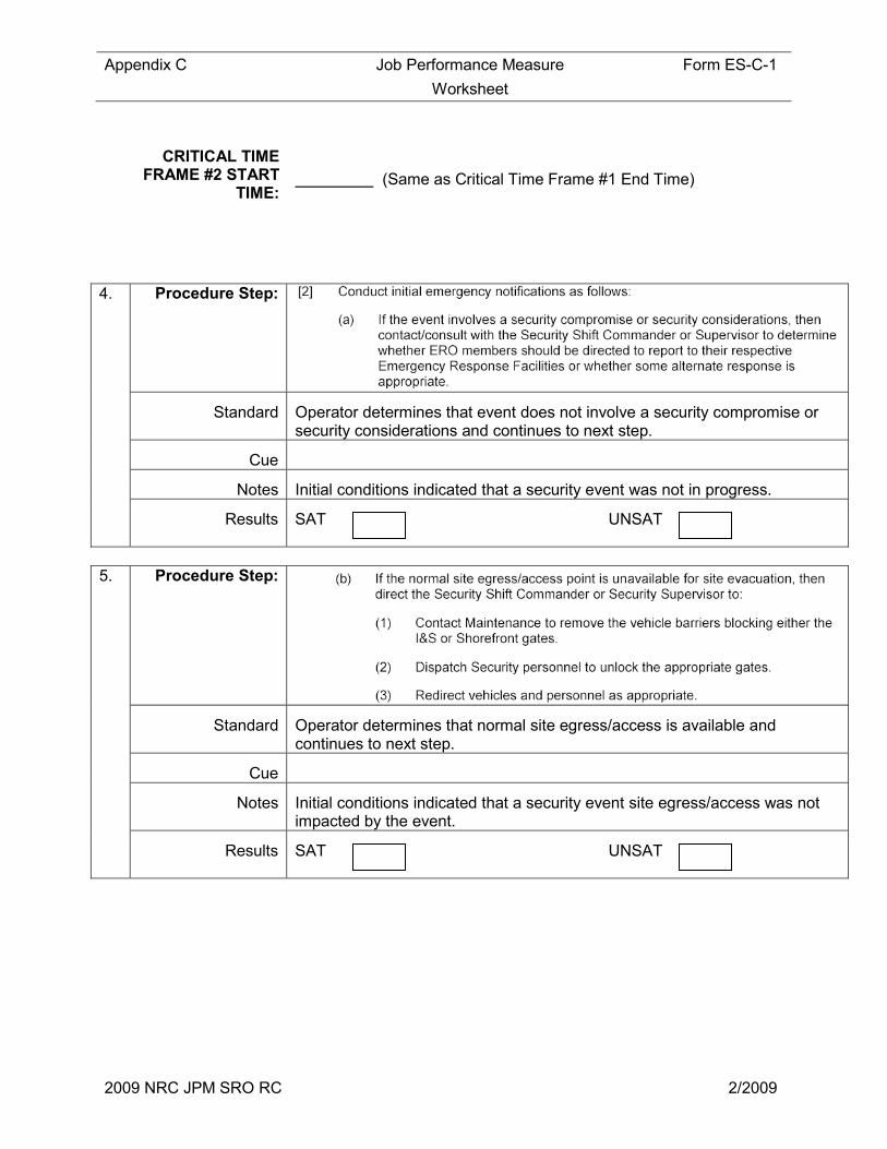
CRITICAL TIME FRAME #2 START
TIME:
(Same as Critical Time Frame #1 End Time)
4. Procedure Step:
Standard Operator determines that event does not involve a security compromise or security considerations and continues to next step.
Cue
Notes Initial conditions indicated that a security event was not in progress.
Results SAT UNSAT
5. Procedure Step:
Standard Operator determines that normal site egress/access is available and continues to next step.
Cue
Notes Initial conditions indicated that a security event site egress/access was not impacted by the event.
Results SAT UNSAT
Appendix C Job Performance Measure Form ES-C-1
Worksheet
2009 NRC JPM SRO RC 2/2009
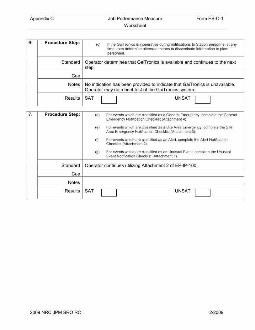
6. Procedure Step:
Standard Operator determines that GaiTronics is available and continues to the next step.
Cue
Notes No indication has been provided to indicate that GaiTronics is unavailable. Operator may do a brief test of the GaiTronics system.
Results SAT UNSAT
7. Procedure Step:
Standard Operator continues utilizing Attachment 2 of EP-IP-100.
Cue
Notes
Results SAT UNSAT
Appendix C Job Performance Measure Form ES-C-1
Worksheet
2009 NRC JPM SRO RC 2/2009
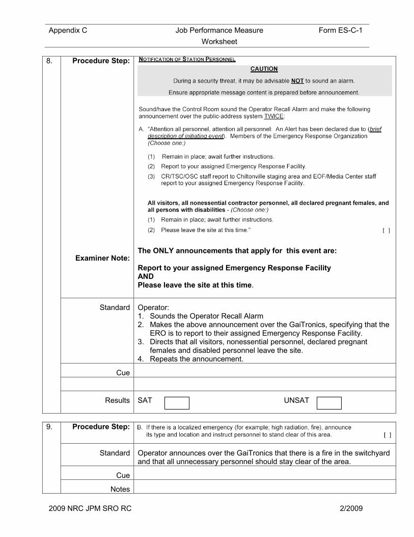
8. Procedure Step:
Examiner Note:
The ONLY announcements that apply for this event are: Report to your assigned Emergency Response Facility AND Please leave the site at this time.
Standard Operator: 1. Sounds the Operator Recall Alarm 2. Makes the above announcement over the GaiTronics, specifying that the
ERO is to report to their assigned Emergency Response Facility. 3. Directs that all visitors, nonessential personnel, declared pregnant
females and disabled personnel leave the site. 4. Repeats the announcement.
Cue
Results SAT UNSAT
9. Procedure Step:
Standard Operator announces over the GaiTronics that there is a fire in the switchyard and that all unnecessary personnel should stay clear of the area.
Cue
Notes

Appendix C Job Performance Measure Form ES-C-1
Worksheet
2009 NRC JPM SRO RC 2/2009
Results SAT UNSAT
10. Procedure Step:
Standard Operator determines that there is no potential for airborne release and continues to the next step.
Cue
Notes
Results SAT UNSAT
11. Procedure Step:
Standard Operator determines the CANS code to be 202.
Cue
Notes If operator does not record the code in the procedure or verbalizes the code then question the operator at the conclusion of the JPM.
Results SAT UNSAT
Appendix C Job Performance Measure Form ES-C-1
Worksheet
2009 NRC JPM SRO RC 2/2009
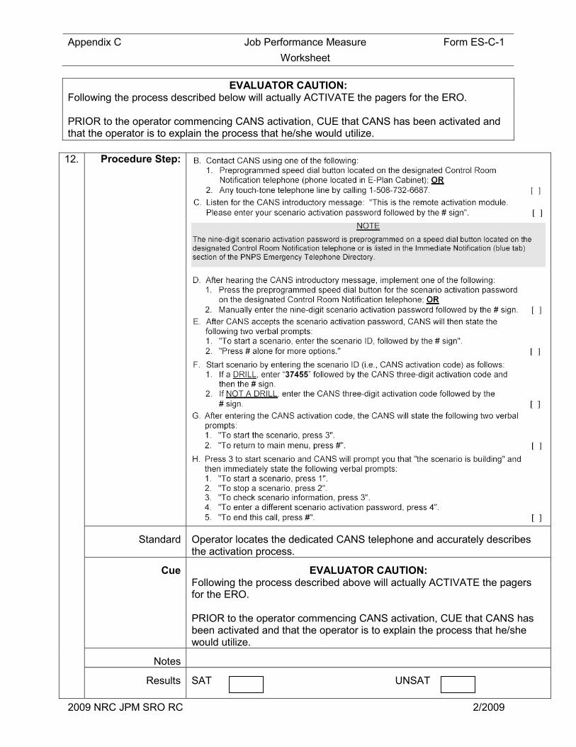
EVALUATOR CAUTION: Following the process described below will actually ACTIVATE the pagers for the ERO. PRIOR to the operator commencing CANS activation, CUE that CANS has been activated and that the operator is to explain the process that he/she would utilize.
12. Procedure Step:
Standard Operator locates the dedicated CANS telephone and accurately describes the activation process.
Cue EVALUATOR CAUTION: Following the process described above will actually ACTIVATE the pagers for the ERO. PRIOR to the operator commencing CANS activation, CUE that CANS has been activated and that the operator is to explain the process that he/she would utilize.
Notes
Results SAT UNSAT

Appendix C Job Performance Measure Form ES-C-1
Worksheet
2009 NRC JPM SRO RC 2/2009
Appendix C Job Performance Measure Form ES-C-1
Worksheet
2009 NRC JPM SRO RC 2/2009
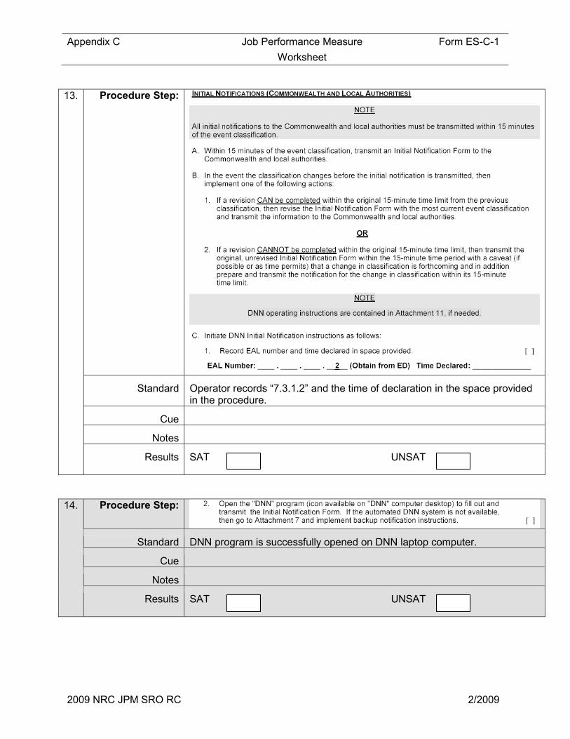
13. Procedure Step:
Standard Operator records “7.3.1.2” and the time of declaration in the space provided in the procedure.
Cue
Notes
Results SAT UNSAT
14. Procedure Step:
Standard DNN program is successfully opened on DNN laptop computer.
Cue
Notes
Results SAT UNSAT

Appendix C Job Performance Measure Form ES-C-1
Worksheet
2009 NRC JPM SRO RC 2/2009
15. Procedure Step:
Standard Blocks 1-7 are completed. Refer to attachment 2 for critical elements of the notification and the required degree of accuracy.
Cue
Notes
Results SAT UNSAT
16. Procedure Step:
Standard Operator activates the “Send” function. Message window displays computer generated message, “Notification sent successfully”.
Cue
Notes Computer generated message will take approximately 10 seconds to appear if successful.
Results SAT UNSAT
Cue: This completes this JPM.
CRITICAL TIME FRAME #1 END TIME:
STOP TIME:
Appendix C Job Performance Measure Form ES-C-1
Worksheet
2009 NRC JPM SRO RC 2/2009
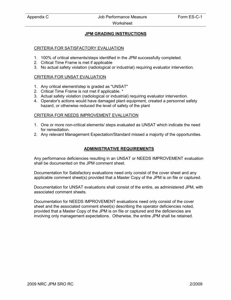
JPM GRADING INSTRUCTIONS
CRITERIA FOR SATISFACTORY EVALUATION
1. 100% of critical elements/steps identified in the JPM successfully completed. 2. Critical Time Frame is met if applicable 3. No actual safety violation (radiological or industrial) requiring evaluator intervention. CRITERIA FOR UNSAT EVALUATION
1. Any critical element/step is graded as "UNSAT" 2. Critical Time Frame is not met if applicable. * 3. Actual safety violation (radiological or industrial) requiring evaluator intervention. 4. Operator's actions would have damaged plant equipment, created a personnel safety
hazard, or otherwise reduced the level of safety of the plant CRITERIA FOR NEEDS IMPROVEMENT EVALUATION 1. One or more non-critical elements/ steps evaluated as UNSAT which indicate the need
for remediation. 2. Any relevant Management Expectation/Standard missed a majority of the opportunities.
ADMINISTRATIVE REQUIREMENTS Any performance deficiencies resulting in an UNSAT or NEEDS IMPROVEMENT evaluation shall be documented on the JPM comment sheet. Documentation for Satisfactory evaluations need only consist of the cover sheet and any applicable comment sheet(s) provided that a Master Copy of the JPM is on file or captured. Documentation for UNSAT evaluations shall consist of the entire, as administered JPM, with associated comment sheets. Documentation for NEEDS IMPROVEMENT evaluations need only consist of the cover sheet and the associated comment sheet(s) describing the operator deficiencies noted, provided that a Master Copy of the JPM is on file or captured and the deficiencies are involving only management expectations. Otherwise, the entire JPM shall be retained.

Appendix C Job Performance Measure Form ES-C-1
Worksheet
2009 NRC JPM SRO RC 2/2009
JPM COMMENT SHEET REQUIREMENTS: • Any operator deficiencies resulting in an UNSAT or NEEDS IMPROVEMENT evaluation
shall be documented. • Any follow-up questions asked and the operator's response must be documented. • Any operator deficiencies which, in themselves, would not result in an UNSAT evaluation
of this JPM but may, when coupled with performance on other JPMs, result in an OVERALL FAILING evaluation for the JPM exam should also be documented below.
• Any other comments, positive or negative, that the evaluator determines is worth noting. COMMENTS:

Appendix C Job Performance Measure Form ES-C-1
Worksheet
2009 NRC JPM SRO RC 2/2009

Appendix C Job Performance Measure Form ES-C-1
Worksheet
2009 NRC JPM SRO RC 2/2009
Attachment 2 - KEY Initial Notification Grading Aid
(Critical Elements are Shaded Grey)
PILGRIM NUCLEAR POWER STATION INITIAL EMERGENCY NOTIFICATION
This is a Training Event Notification Number: 1 _____________________________________________________________ As of __:__ on __/__/_____, Pilgrim Station has Entered an Alert. Degree of Accuracy: Time, ± 1 min of Declared Time Date, Today’s Date _________________________________________________________ EAL Number: 7.3.1.2. Degree of Accuracy: Exact ____________________________________________________________ Description of Event: Any of the following events occurring which affect plant operation: --Aircraft crash on facility. --Missile impact from any source on the facility. --Entry of toxic or flammable gas into a plant process building atmosphere (includes significant Main Generator hydrogen leaks). -- Explosion (unplanned). Note: Computer Fills this in Automatically __________________________________________________________ Emergency Radioactive Release IS NOT in progress. Degree of Accuracy: Exact _____________________________________________________________ Emergency Radioactive Release IS BELOW Protective Action Guides. Note: Computer Fills this in Automatically _____________________________________________________________ Meteorological Data as of __:__ on __/__/_____,: Wind Direction FROM 264 degrees TO 84 degrees at 13 miles per hour. _

Appendix C Job Performance Measure Form ES-C-1
Worksheet
2009 NRC JPM SRO RC 2/2009
____________________________________________________________ PNPS’s Protective Action Recommendations: NO Protective Actions Necessary. Note: Computer Fills this in Automatically ___________________________________________________________ Notification initiated by _______ at (not yet sent). (ENTERGY.COM\________ from NPI-D9HJHHF1)
This is a Training Event
Approved by ______________________________

Appendix C Job Performance Measure Form ES-C-1
Worksheet
2009 NRC JPM SRO RC 2/2009
INITIAL CONDITIONS: ATTACHMENT 1
1) PNPS was at full power when a load reject and loss of off-site power occurred.
2) All control rods fully inserted.
3) Both Emergency Diesel Generators Started and 4160 VAC buses A5 and A6 have been re-energized. All other 4160 VAC buses have de-energized.
4) The security shift commander has called the control room and reported that a small aircraft crashed into the switchyard and that three 345 KV ACBs have been severely damaged. The aircraft is on fire and off-site fire fighting assistance is recommended. No PNPS equipment is currently engulfed by the fire.
5) Following the scram, RPV Level lowered to - 47 inches. Both RCIC and HPCI auto started and aligned for injection.
6) HPCI was manually shifted to pressure control when RPV level recovered to the normal band.
7) RPV level is currently stable at 20 inches being controlled by RCIC
8) RPV pressure is currently 900 psig and slowly lowering with HPCI in pressure control.
9) The Control Room Supervisor is coordinating overall plant response, including fire brigade response and notification of Plymouth Fire.
10) All containment parameters are normal, with the exception of Torus Water Temperature. Torus Water Temperature has just exceeded 80 degrees.
11) The security shift commander has determined that this is not a security event and that plant access and egress has not been impacted.
12) Weather conditions are as indicated on Panel MT1
INITIATING CUE:
You are the Third SRO on shift. The Shift Manager is incapacitated. Implement the Emergency Plan as required.

Appendix C Job Performance Measure Form ES-C-1
Worksheet
2009 NRC JPM SRO RC 2/2009
Facility: PILGRIM Task No.: NEW
Task Title: Perform Daily Log Test #31 – High Range Effluent Monitors
JPM No.: 2009 NRC JPM SRO RC
K/A Reference: K/A: 2.3.11 (3.8)
Ability to control radiation releases.
Examinee: NRC Examiner:
Facility Evaluator: Date:
Method of testing:
Simulated Performance: Actual Performance: X
Classroom Simulator X Plant
READ TO THE EXAMINEE
I will explain the initial conditions, which steps to simulate or discuss, and provide initiating cues. When you complete the task successfully, the objective for this Job Performance Measure will be satisfied.
Initial Conditions: Plant conditions are as follows:
• Plant conditions are stable.
Task Standard: Performs the test and determines that Reactor Building Vent Effluent Rad Monitor is OOS and TS Table 3.2.F. Action (7) applies
Required Materials: PNPS 2.1.15 Daily Log test #31
General References: PNPS 2.1.15 Daily Log test #31
Initiating Cue: You are directed to perform Daily Log Test #31 - High Range Effluent Monitors and determine any required actions.

Appendix C Job Performance Measure Form ES-C-1
Worksheet
2009 NRC JPM SRO RC 2/2009
Time Critical Task: NO
Validation Time: 15 minutes
Appendix C Job Performance Measure Form ES-C-1
Worksheet
2009 NRC JPM SRO RC 2/2009
SIMULATOR SETUP
1. Set the value for RBV Rad Monitor “RT-1001-609” to indicate <103 R/hr when the switch is placed in “check”.

Appendix C Page 67 of 235 Form ES-C-1
PERFORMANCE INFORMATION
2009 NRC JPM SRO RC 2/2009
Critical Steps in Shaded
START TIME:
Performance Step: 1 Obtain and review PNPS 2.1.15 , Daily Log Test #31
Standard: Obtains and reviews PNPS 2.1.15 , Daily Log Test #31
Comment:
Performance Step: 2
Standard: Review the statements at the beginning of the test
Comment:
Appendix C Page 68 of 235 Form ES-C-1
PERFORMANCE INFORMATION
2009 NRC JPM SRO RC 2/2009
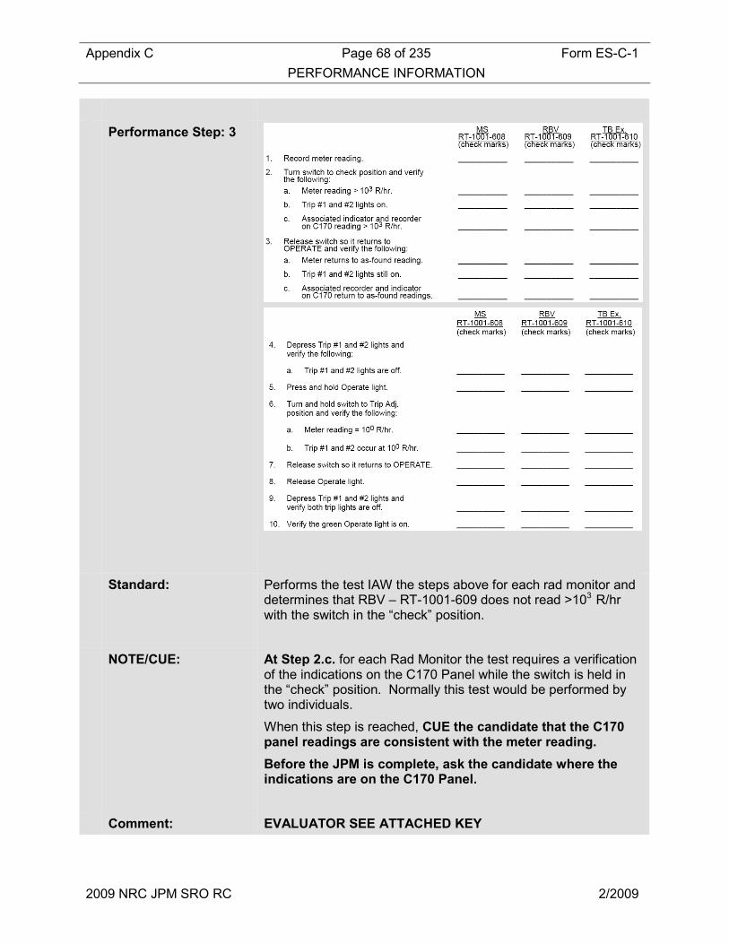
Performance Step: 3
Standard: Performs the test IAW the steps above for each rad monitor and determines that RBV – RT-1001-609 does not read >103 R/hr with the switch in the “check” position.
NOTE/CUE: At Step 2.c. for each Rad Monitor the test requires a verification of the indications on the C170 Panel while the switch is held in the “check” position. Normally this test would be performed by two individuals.
When this step is reached, CUE the candidate that the C170 panel readings are consistent with the meter reading.
Before the JPM is complete, ask the candidate where the indications are on the C170 Panel.
Comment: EVALUATOR SEE ATTACHED KEY
Appendix C Page 69 of 235 Form ES-C-1
PERFORMANCE INFORMATION
2009 NRC JPM SRO RC 2/2009
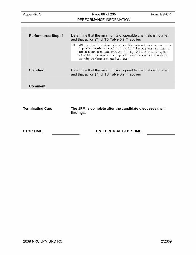
Performance Step: 4 Determine that the minimum # of operable channels is not met and that action (7) of TS Table 3.2.F. applies
Standard: Determine that the minimum # of operable channels is not met and that action (7) of TS Table 3.2.F. applies
Comment:
Terminating Cue: The JPM is complete after the candidate discusses their findings.
STOP TIME: TIME CRITICAL STOP TIME:

Appendix C Page 70 of 235 Form ES-C-1
VERIFICATION OF COMPLETION
2009 NRC JPM SRO RC 2/2009
Job Performance Measure No.: 2009 AUDIT JPM SRO RC
Examinee’s Name:
Date Performed:
Facility Evaluator:
Number of Attempts:
Time to Complete:
Question Documentation:
Question:
Response:
Result: SAT UNSAT
Examiner’s Signature: Date:

Scenario Event Description ES-D1
Pilgrim 2009 NRC Scenario 1
- 71 -
Initial Conditions: Plant conditions are as follows:
• Plant conditions are stable. Initiating Cue: You are directed to perform Daily Log Test #31 - High Range
Effluent Monitors and determine any required actions.
Scenario Event Description ES-D1
Pilgrim 2009 NRC Scenario 1
- 72 -
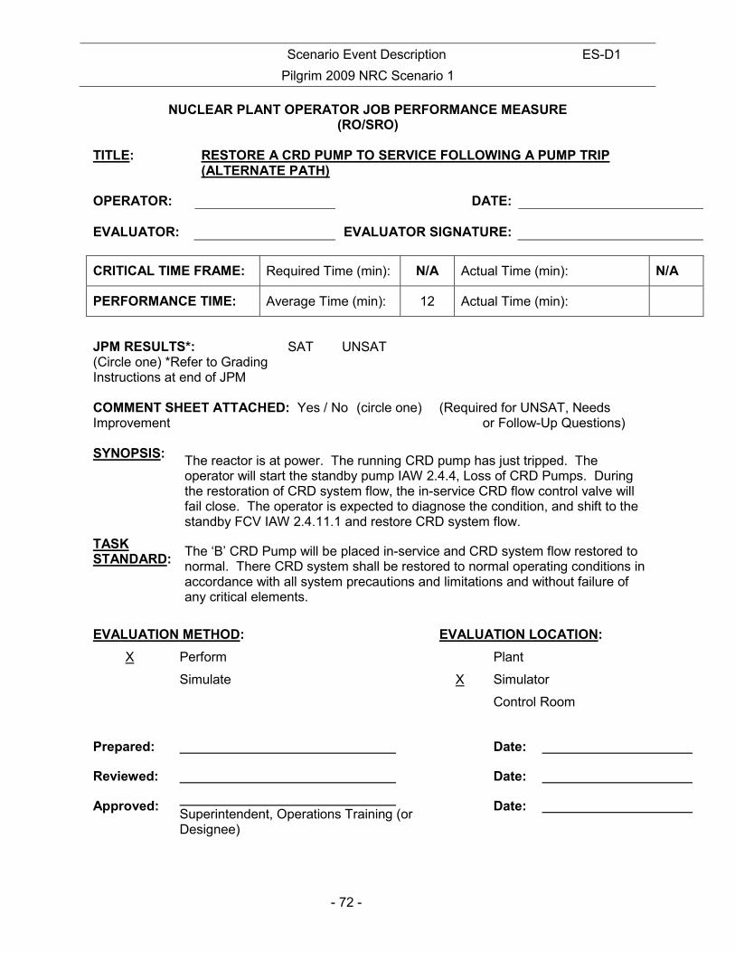
NUCLEAR PLANT OPERATOR JOB PERFORMANCE MEASURE (RO/SRO)
TITLE: RESTORE A CRD PUMP TO SERVICE FOLLOWING A PUMP TRIP
(ALTERNATE PATH) OPERATOR:
DATE:
EVALUATOR:
EVALUATOR SIGNATURE:
CRITICAL TIME FRAME: Required Time (min): N/A Actual Time (min): N/A
PERFORMANCE TIME: Average Time (min): 12 Actual Time (min):
JPM RESULTS*: (Circle one) *Refer to Grading Instructions at end of JPM
SAT UNSAT
COMMENT SHEET ATTACHED: Yes / No (circle one) (Required for UNSAT, Needs Improvement or Follow-Up Questions) SYNOPSIS:
The reactor is at power. The running CRD pump has just tripped. The operator will start the standby pump IAW 2.4.4, Loss of CRD Pumps. During the restoration of CRD system flow, the in-service CRD flow control valve will fail close. The operator is expected to diagnose the condition, and shift to the standby FCV IAW 2.4.11.1 and restore CRD system flow.
TASK STANDARD:
The ‘B’ CRD Pump will be placed in-service and CRD system flow restored to normal. There CRD system shall be restored to normal operating conditions in accordance with all system precautions and limitations and without failure of any critical elements.
EVALUATION METHOD: EVALUATION LOCATION:
X Perform Plant
Simulate X Simulator
Control Room
Prepared: Date:
Reviewed: Date:
Approved: Superintendent, Operations Training (or Designee)
Date:

Scenario Event Description ES-D1
Pilgrim 2009 NRC Scenario 1
- 73 -
TASK Title: Task Number K&A SYSTEM: K&A RATING:
SHIFT CRD FLOW CONTROL VALVE
201-01-04-012 201001 3.2/3.1 A2.07
REFERENCES: PNPS 2.4.4, Loss of CRD Pumps 2.4.11.1, CRD System Malfunctions SIMULATOR CONDITIONS: 5. Initialize the simulator to any IC 6. Insert a CRD pump trip on the running CRD pump
• RD05 CRD Hydraulic Pump A Trip 7. Insert the CRD Flow Control Valve Fails Close Malfunction for the in-service flow control
valve. Condition the malfunction to go active when the RED open indication for that valve is FALSE. • RD02 CRD Flow Control Valve 6AF • Cue Off – ‘A’ FCV Red Light OFF
8. Acknowledge all alarms. 9. An IOS operator is standing by to support the operator in responding to the JPM. GENERAL TOOLS AND EQUIPMENT: 2. None CRITICAL ELEMENTS: Critical elements are shaded in gray within the body of this document. OPERATOR BRIEF: 2. State the following paragraph IF this is the first performance in this setting:
a) “All actions associated with this job performance measure are to be performed. You will be provided access to any tools or equipment you determine necessary to perform the task. When a second checker is called for, the evaluator will perform the role of second checker and will always be in agreement with your actions. Before you start, the evaluator will state the task conditions and answer any questions, then provide a cue to begin”.
3. The task conditions are as follows:
i) The reactor is operating at power
ii) CRD Pump A has just tripped.
iii) Off-normal procedure 2.4.4, Loss of CRD Pumps, has just been entered.
4. Solicit and answer any questions the operator may have.
Scenario Event Description ES-D1
Pilgrim 2009 NRC Scenario 1
- 74 -
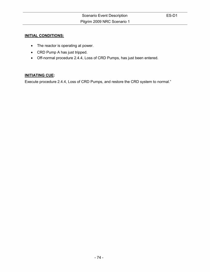
INITIAL CONDITIONS:
• The reactor is operating at power.
• CRD Pump A has just tripped.
• Off-normal procedure 2.4.4, Loss of CRD Pumps, has just been entered. INITIATING CUE:
Execute procedure 2.4.4, Loss of CRD Pumps, and restore the CRD system to normal.”

Scenario Event Description ES-D1
Pilgrim 2009 NRC Scenario 1
- 75 -
PERFORMANCE:
Notes This task is covered in 2.4.4. The actions for the Flow Control Valve failure are addressed in procedure 2.4.11.1, section Attachment 5.
All controls are located on panel C905.
All critical steps must be performed in order written unless otherwise noted
START TIME:
9. Procedure Step: Operator obtains a copy of procedure 2.4.4 and reviews the immediate action;
Standard Operator determines that Reactor Pressure is > 950 psig and that the immediate actions are not applicable, regardless of the status of accumulator alarms.
Cue
Notes Multiple RPV pressure indicators located immediately above the CRD system controls.
Results SAT UNSAT
Scenario Event Description ES-D1
Pilgrim 2009 NRC Scenario 1
- 76 -
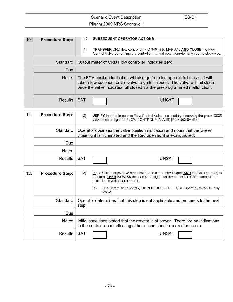
10. Procedure Step:
Standard Output meter of CRD Flow controller indicates zero.
Cue
Notes The FCV position indication will also go from full open to full close. It will take a few seconds for the valve to go full closed. The valve will fail close once the valve indicates full closed via the pre-programmed malfunction.
Results SAT UNSAT
11. Procedure Step:
Standard Operator observes the valve position indication and notes that the Green close light is illuminated and the Red open light is extinguished.
Cue
Notes
Results SAT UNSAT
12. Procedure Step:
Standard Operator determines that this step is not applicable and proceeds to the next step.
Cue
Notes Initial conditions stated that the reactor is at power. There are no indications in the control room indicating either a load shed or a reactor scram.
Results SAT UNSAT
Scenario Event Description ES-D1
Pilgrim 2009 NRC Scenario 1
- 77 -
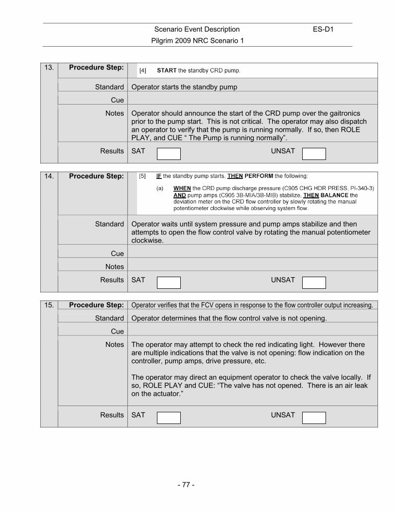
13. Procedure Step:
Standard Operator starts the standby pump
Cue
Notes Operator should announce the start of the CRD pump over the gaitronics prior to the pump start. This is not critical. The operator may also dispatch an operator to verify that the pump is running normally. If so, then ROLE PLAY, and CUE “ The Pump is running normally”.
Results SAT UNSAT
14. Procedure Step:
Standard Operator waits until system pressure and pump amps stabilize and then attempts to open the flow control valve by rotating the manual potentiometer clockwise.
Cue
Notes
Results SAT UNSAT
15. Procedure Step: Operator verifies that the FCV opens in response to the flow controller output increasing.
Standard Operator determines that the flow control valve is not opening.
Cue
Notes The operator may attempt to check the red indicating light. However there are multiple indications that the valve is not opening: flow indication on the controller, pump amps, drive pressure, etc. The operator may direct an equipment operator to check the valve locally. If so, ROLE PLAY and CUE: “The valve has not opened. There is an air leak on the actuator.”
Results SAT UNSAT
Scenario Event Description ES-D1
Pilgrim 2009 NRC Scenario 1
- 78 -
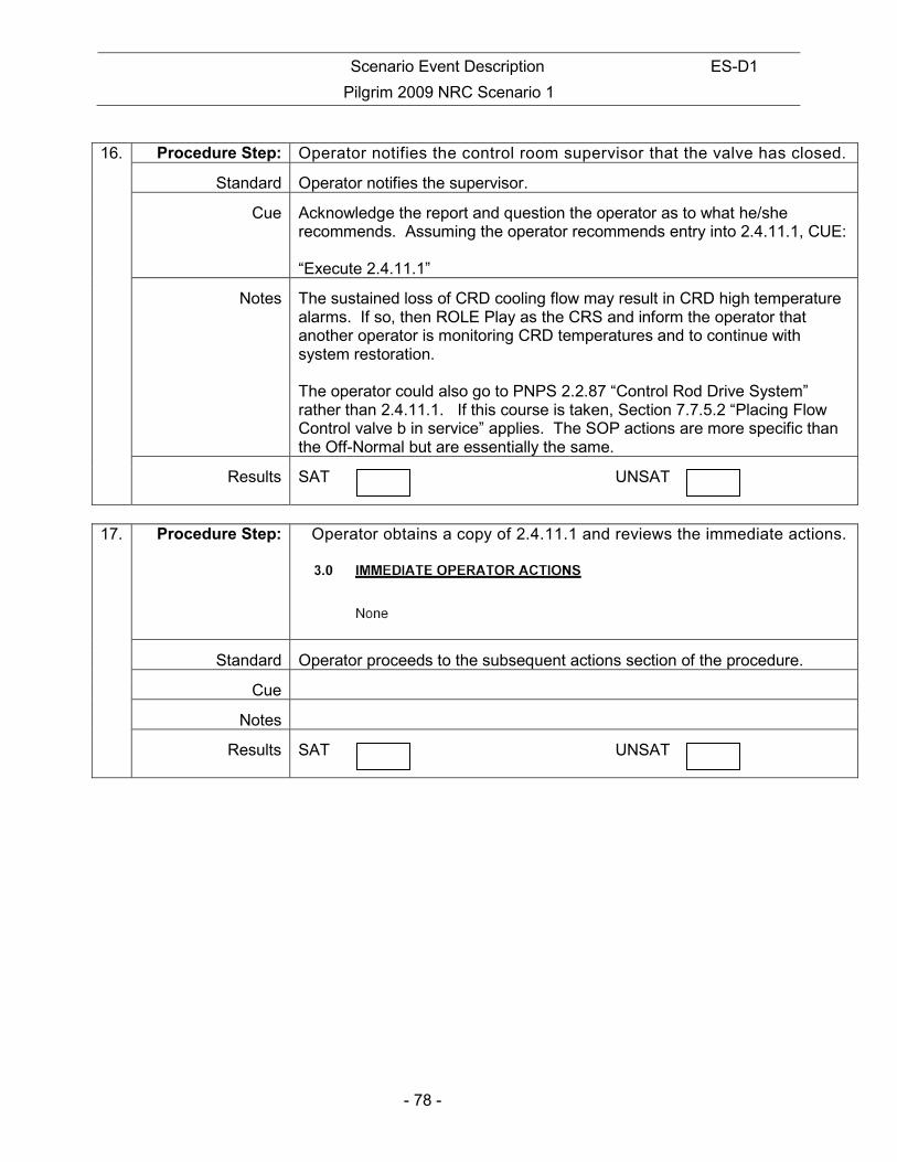
16. Procedure Step: Operator notifies the control room supervisor that the valve has closed.
Standard Operator notifies the supervisor.
Cue Acknowledge the report and question the operator as to what he/she recommends. Assuming the operator recommends entry into 2.4.11.1, CUE: “Execute 2.4.11.1”
Notes The sustained loss of CRD cooling flow may result in CRD high temperature alarms. If so, then ROLE Play as the CRS and inform the operator that another operator is monitoring CRD temperatures and to continue with system restoration. The operator could also go to PNPS 2.2.87 “Control Rod Drive System” rather than 2.4.11.1. If this course is taken, Section 7.7.5.2 “Placing Flow Control valve b in service” applies. The SOP actions are more specific than the Off-Normal but are essentially the same.
Results SAT UNSAT
17. Procedure Step: Operator obtains a copy of 2.4.11.1 and reviews the immediate actions.
Standard Operator proceeds to the subsequent actions section of the procedure.
Cue
Notes
Results SAT UNSAT
Scenario Event Description ES-D1
Pilgrim 2009 NRC Scenario 1
- 79 -
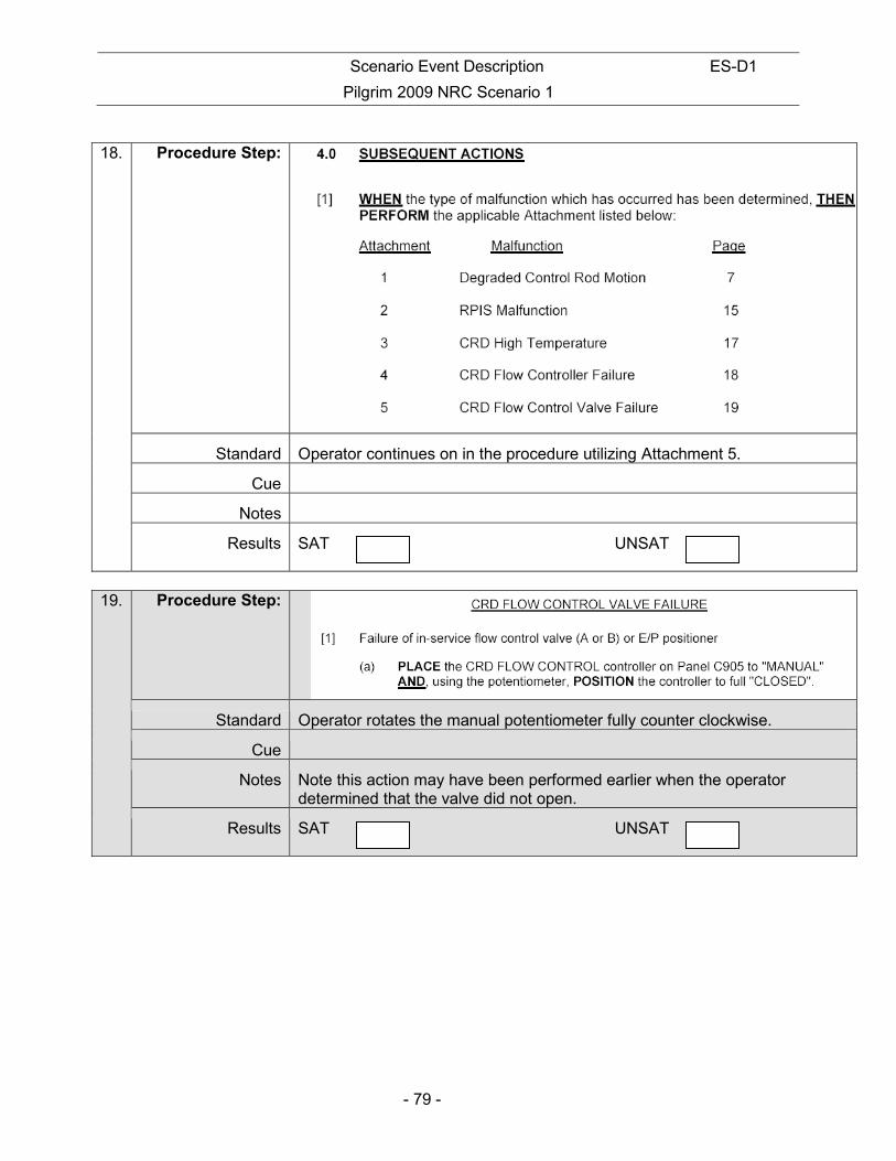
18. Procedure Step:
Standard Operator continues on in the procedure utilizing Attachment 5.
Cue
Notes
Results SAT UNSAT
19. Procedure Step:
Standard Operator rotates the manual potentiometer fully counter clockwise.
Cue
Notes Note this action may have been performed earlier when the operator determined that the valve did not open.
Results SAT UNSAT

Scenario Event Description ES-D1
Pilgrim 2009 NRC Scenario 1
- 80 -
20. Procedure Step:
Standard Operator contacts an equipment operator and directs/coordinates the performance of step [2].
Cue IOS Operator is to role play as necessary to support this step. IOS operator is to utilize remote functions as directed by the operator.
Notes
Results SAT UNSAT
21. Procedure Step:
Standard Operator opens the FCV and raises flow by rotating the manual potentiometer in the clockwise direction and observing flow increase. Flow indication on controller rises to 50 gpm. RED status light comes ON
Cue
Notes
Results SAT UNSAT
22. Procedure Step:
Standard Operator checks pressures and determines that they are normal.
Cue
Notes Operator may determine that adjustments are required. However this is not expected. Note per, 2.1.35, Control room readings, CRD drive pressure is 150 to 250 psid. Cooling water pressure is normally 8-15 psid.
Results SAT UNSAT

Scenario Event Description ES-D1
Pilgrim 2009 NRC Scenario 1
- 81 -
23. Procedure Step:
Standard Flow Controller is placed in AUTO position
Cue
Notes
Results SAT UNSAT
Cue: This completes this JPM.
STOP TIME:

Scenario Event Description ES-D1
Pilgrim 2009 NRC Scenario 1
- 82 -
INITIAL CONDITIONS:
• The reactor is operating at power.
• CRD Pump A has just tripped.
• Off-normal procedure 2.4.4, Loss of CRD Pumps, has just been entered. INITIATING CUE:
Execute procedure 2.4.4, Loss of CRD Pumps, and restore the CRD system to normal.”

Scenario Event Description ES-D1
Pilgrim 2009 NRC Scenario 1
- 83 -
NUCLEAR PLANT OPERATOR JOB PERFORMANCE MEASURE (RO/SRO)
TITLE: PLACING THE FIRST FEEDWATER REGULATING VALVE IN SERVICE
OPERATOR:
DATE:
EVALUATOR:
EVALUATOR SIGNATURE:
CRITICAL TIME FRAME: Required Time (min): N/A Actual Time (min): N/A
PERFORMANCE TIME: Average Time (min): 12 Actual Time (min):
JPM RESULTS*: (Circle one) *Refer to Grading Instructions at end of JPM
SAT UNSAT NEEDS IMPROVEMENT
COMMENT SHEET ATTACHED: Yes / No (circle one) (Required for Unsat, Needs Improvement or Follow-Up Questions) SYNOPSIS:
The reactor is in a normal startup configuration at ~10% power and a main feed regulating valve needs to be placed in service to continue the startup.
TASK STANDARD:
One Main Feed Reg. Valve is in service controlling vessel level with the startup regulator closed. Reactor water level will be maintained between the low level scram and main turbine trip setpoints. The system shall be operated in accordance with all applicable precautions and limitations. The system procedure shall be followed without failure of critical elements.
EVALUATION METHOD: EVALUATION LOCATION:
X Perform Plant
Simulate X Simulator
Control Room
Prepared: Date:
Reviewed: Date:
Approved: Superintendent, Operations Training (or Designee)
Date:

Scenario Event Description ES-D1
Pilgrim 2009 NRC Scenario 1
- 84 -
TASK Title: Task Number K&A SYSTEM: K&A RATING:
PLACE THE FEEDWATER CONTROLS FROM MANUAL TO AUTO.
259-01-01-006
259002
3.8/3.6 A4.03
REFERENCES: PNPS 2.2.82 SIMULATOR CONDITIONS: 10. Reset the simulator to a condition with Rx power at approximately 10 - 12% and level
controlled on the startup regulator. 11. Simulator Conditions are consistent with PNPS 2.1.1 Rx Plant Startup Step[110](b) 12. Insert Malfunction FW06 Master Controller Fails High in Auto 13. Verify both downstream blocks are open 14. FWLC is aligned for single element control. 15. Adjust the setpoint tape adjust on the Master Controller to achieve a mismatch between
actual level and the setpoint. Setpoint should be outside the + 25 to 30” band. 16. Verify EPIC is operating GENERAL TOOLS AND EQUIPMENT: 3. None CRITICAL ELEMENTS: Critical elements are shaded in gray within the body of this document. OPERATOR BRIEF: 5. State the following paragraph IF this is the first performance in this setting:
a) “All actions associated with this job performance measure are to be performed. You will be provided access to any tools or equipment you determine necessary to perform the task. When a second checker is called for, the evaluator will perform the role of second checker and will always be in agreement with your actions. Before you start, the evaluator will state the task conditions and answer any questions, then provide a cue to begin”.
2. The task conditions are as follows:
i) A plant startup is in progress IAW 2.1.1. Step[110]
ii) The mode switch is in Run
iii) Reactor power is approximately 10%
3. Solicit and answer any questions the operator may have.

Scenario Event Description ES-D1
Pilgrim 2009 NRC Scenario 1
- 85 -
INITIAL CONDITIONS: • A plant startup is in progress IAW 2.1.1. Step[110]
• The mode switch is in Run
• Reactor power is approximately 10%
INITIATING CUE: IAW procedure 2.2.82 Section 7.1.1, place the “A” main feed reg valve in service and secure the startup feed reg valve. Inform me when you have completed this task.” The ATC operator will be standing by to monitor reactor power and adjust IRM Range Switches if required during the evolution.

Scenario Event Description ES-D1
Pilgrim 2009 NRC Scenario 1
- 86 -
PERFORMANCE: EXAMINER NOTE: An ATC operator will be standing by to monitor reactor power and adjust IRM Range Switches if required during the evolution.
Notes This task is covered in 2.2.82, section 7.1.1.
All components are located on 905 horizontal and vertical section unless otherwise noted.
All critical steps must be performed in order written unless otherwise noted.
START TIME:
24. Procedure Step: CAUTION If the piping between 1st Point Feedwater Heater Outlet Block Valves, MO-3479/3480, and Feedwater Regulating Valves, FV-642A/B has been isolated for an extended period of time (as determined by the SM/CRS), then the differential pressure between this piping and the RFP Discharge Header pressure shall be checked in accordance with Attachment 4 (Feedwater Piping Pressure Monitoring) prior to placing a Feedwater Regulating Valve into service.
Standard Operator questions the SM/CRS as to whether there is a concern with the differential pressure in the Feedwater discharge header.
Cue If asked cue: We have determined that the Feedwater piping pressure is equalized between the1st Point Feedwater Heater Outlet Block Valves and the Feedwater Regulating Valves using attachment 4.
Notes The operator may ask this question during his/her procedure review prior to commencing the evolution.
Results SAT UNSAT
25. Procedure Step: VERIFY the following: The MASTER LEVEL CONTROL in "MANUAL" and the Manual control knob is turned FULLY COUNTERCLOCKWISE.
Standard Operator verifies: Control switch for the MASTER controller is aligned to Manual Manual control knob (knurled knob) is set to minimum by attempting to turn knurled knob counterclockwise.
Cue Notes
Results SAT UNSAT
Scenario Event Description ES-D1
Pilgrim 2009 NRC Scenario 1
- 87 -
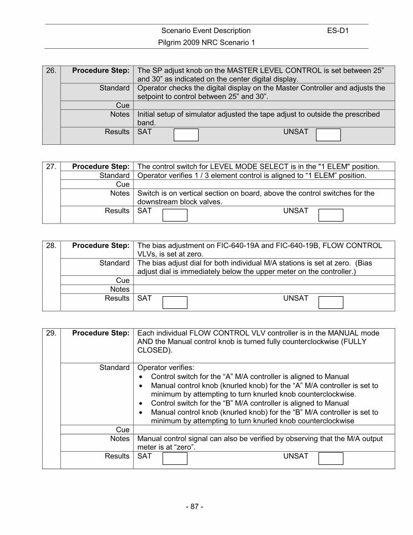
26. Procedure Step: The SP adjust knob on the MASTER LEVEL CONTROL is set between 25”
and 30” as indicated on the center digital display. Standard Operator checks the digital display on the Master Controller and adjusts the
setpoint to control between 25” and 30”. Cue
Notes Initial setup of simulator adjusted the tape adjust to outside the prescribed band.
Results SAT UNSAT
27. Procedure Step: The control switch for LEVEL MODE SELECT is in the "1 ELEM" position. Standard Operator verifies 1 / 3 element control is aligned to “1 ELEM” position.
Cue Notes Switch is on vertical section on board, above the control switches for the
downstream block valves. Results SAT UNSAT
28. Procedure Step: The bias adjustment on FIC-640-19A and FIC-640-19B, FLOW CONTROL VLVs, is set at zero.
Standard The bias adjust dial for both individual M/A stations is set at zero. (Bias adjust dial is immediately below the upper meter on the controller.)
Cue Notes
Results SAT UNSAT
29. Procedure Step: Each individual FLOW CONTROL VLV controller is in the MANUAL mode AND the Manual control knob is turned fully counterclockwise (FULLY CLOSED).
Standard Operator verifies: • Control switch for the “A” M/A controller is aligned to Manual • Manual control knob (knurled knob) for the “A” M/A controller is set to
minimum by attempting to turn knurled knob counterclockwise. • Control switch for the “B” M/A controller is aligned to Manual • Manual control knob (knurled knob) for the “B” M/A controller is set to
minimum by attempting to turn knurled knob counterclockwise Cue
Notes Manual control signal can also be verified by observing that the M/A output meter is at “zero”.
Results SAT UNSAT
Scenario Event Description ES-D1
Pilgrim 2009 NRC Scenario 1
- 88 -
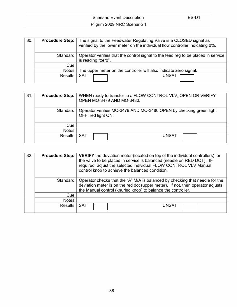
30. Procedure Step: The signal to the Feedwater Regulating Valve is a CLOSED signal as
verified by the lower meter on the individual flow controller indicating 0%.
Standard Operator verifies that the control signal to the feed reg to be placed in service is reading “zero”.
Cue Notes The upper meter on the controller will also indicate zero signal.
Results SAT UNSAT
31. Procedure Step: WHEN ready to transfer to a FLOW CONTROL VLV, OPEN OR VERIFY OPEN MO-3479 AND MO-3480.
Standard Operator verifies MO-3479 AND MO-3480 OPEN by checking green light OFF, red light ON.
Cue Notes
Results SAT UNSAT
32. Procedure Step: VERIFY the deviation meter (located on top of the individual controllers) for the valve to be placed in service is balanced (needle on RED DOT). IF required, adjust the selected individual FLOW CONTROL VLV Manual control knob to achieve the balanced condition.
Standard Operator checks that the “A” M/A is balanced by checking that needle for the deviation meter is on the red dot (upper meter). If not, then operator adjusts the Manual control (knurled knob) to balance the controller.
Cue Notes
Results SAT UNSAT

Scenario Event Description ES-D1
Pilgrim 2009 NRC Scenario 1
- 89 -
33. Procedure Step: NOTE
Refer to Precaution 5.0[4].
SWITCH the individual controller for the selected FLOW CONTROL VLV to the "AUTO" position. The valve is now under MASTER/MANUAL control.
Standard Operator rotates control switch for “A” M/ A station to the “AUTO” position. Cue
Notes Precaution #4 states: When placing a Feedwater Regulating Valve in or out of service or switching from MANUAL to AUTO, consider monitoring computer points FWR114 (Feedline "A" Flow) and FWR116 (Feedline "B" Flow) on EPIC to watch for flow oscillations. Operator may call up EPIC points to monitor feed flows.
Results SAT UNSAT
34. Procedure Step: SLOWLY ADJUST the SP adjust knob on the MASTER LEVEL CONTROL until the master controller deviation meter to the right of the digital display is just balanced (needle in the center).
Standard Operator adjusts the setpoint knob until the deviation meter on the MASTER controller is balanced.
Cue Notes This step may or may not be critical depending upon actual water level and
its relationship to the setpoint tape adjust. This JPM is written assuming that there is a delta and therefore an adjustment of the tape is required.
Results SAT UNSAT
35. Procedure Step: SWITCH the MASTER LEVEL CONTROL to the "AUTO" position. The valve is now under MASTER/AUTO control.
Standard Operator rotates the control switch for the MASTER Controller to the AUTO position.
Cue Notes When Master Controller is placed in AUTO it will fail High. The operator
recognizes the FRV failed open and RPV Level increasing. Operator responds to Annunciator and/or increasing level IAW next JPM step
Results SAT UNSAT
Scenario Event Description ES-D1
Pilgrim 2009 NRC Scenario 1
- 90 -
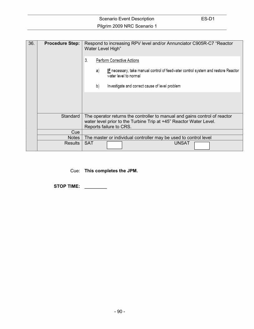
36. Procedure Step: Respond to increasing RPV level and/or Annunciator C905R-C7 “Reactor
Water Level High”
Standard The operator returns the controller to manual and gains control of reactor water level prior to the Turbine Trip at +45” Reactor Water Level. Reports failure to CRS.
Cue Notes The master or individual controller may be used to control level
Results SAT UNSAT
Cue: This completes the JPM.
STOP TIME:
Scenario Event Description ES-D1
Pilgrim 2009 NRC Scenario 1
- 91 -
INITIAL CONDITIONS: • A plant startup is in progress IAW 2.1.1. Step[110]
• The mode switch is in Run
• Reactor power is approximately 10%
INITIATING CUE: IAW procedure 2.2.82 Section 7.1.1, place the “A” main feed reg valve in service and secure the startup feed reg valve. Inform me when you have completed this task.” The ATC operator will be standing by to monitor reactor power and adjust IRM Range Switches if required during the evolution.
NUCLEAR PLANT OPERATOR JOB PERFORMANCE MEASURE
Scenario Event Description ES-D1
Pilgrim 2009 NRC Scenario 1
- 92 -
(RO/SRO) TITLE: RESTORATION OF POWER TO 4160 VAC BUS A-5 FROM THE STARTUP
TRANSFORMER OPERATOR:
DATE:
EVALUATOR:
EVALUATOR SIGNATURE:
CRITICAL TIME FRAME: Required Time (min): N/A Actual Time (min): N/A
PERFORMANCE TIME: Average Time (min): 11 Actual Time (min):
JPM RESULTS*: (Circle one) *Refer to Grading Instructions at end of JPM
SAT UNSAT NEEDS IMPROVEMENT
COMMENT SHEET ATTACHED: Yes / No (circle one) (Required for Unsat, Needs Improvement or Follow-Up Questions) SYNOPSIS:
Following an initial loss of Off-Site power both diesel generators have started and re-energized their respective safety buses. The operator will perform a dead bus transfer and transfer the A5 bus back to the startup transformer.
TASK STANDARD:
Power is restored to 4160 VAC bus A-5 via the Startup Transformer. The system shall be operated in accordance with all applicable precautions and limitations. The procedure shall be followed without a failure of critical elements.
EVALUATION METHOD: EVALUATION LOCATION:
X Perform Plant
Simulate X Simulator
Control Room
Prepared: Date:
Reviewed: Date:
Approved: Superintendent, Operations Training (or Designee)
Date:
Scenario Event Description ES-D1
Pilgrim 2009 NRC Scenario 1
- 93 -
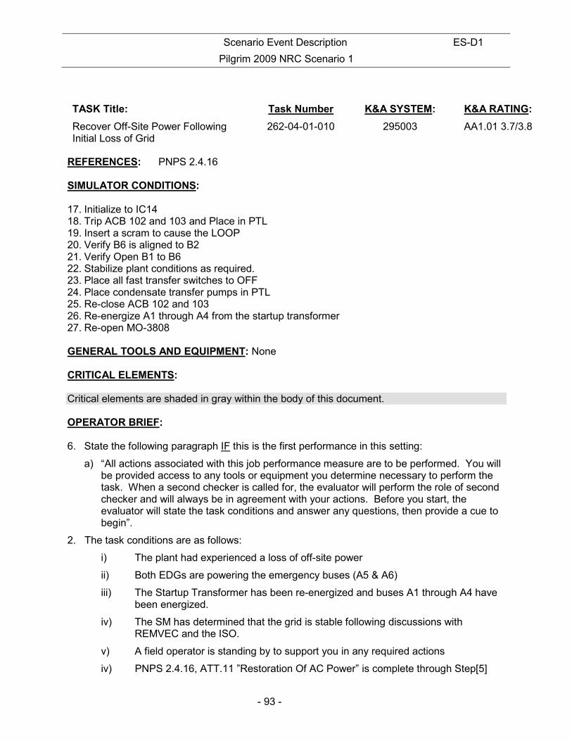
TASK Title: Task Number K&A SYSTEM: K&A RATING:
Recover Off-Site Power Following Initial Loss of Grid
262-04-01-010 295003 AA1.01 3.7/3.8
REFERENCES: PNPS 2.4.16 SIMULATOR CONDITIONS: 17. Initialize to IC14 18. Trip ACB 102 and 103 and Place in PTL 19. Insert a scram to cause the LOOP 20. Verify B6 is aligned to B2 21. Verify Open B1 to B6 22. Stabilize plant conditions as required. 23. Place all fast transfer switches to OFF 24. Place condensate transfer pumps in PTL 25. Re-close ACB 102 and 103 26. Re-energize A1 through A4 from the startup transformer 27. Re-open MO-3808 GENERAL TOOLS AND EQUIPMENT: None CRITICAL ELEMENTS: Critical elements are shaded in gray within the body of this document. OPERATOR BRIEF: 6. State the following paragraph IF this is the first performance in this setting:
a) “All actions associated with this job performance measure are to be performed. You will be provided access to any tools or equipment you determine necessary to perform the task. When a second checker is called for, the evaluator will perform the role of second checker and will always be in agreement with your actions. Before you start, the evaluator will state the task conditions and answer any questions, then provide a cue to begin”.
2. The task conditions are as follows:
i) The plant had experienced a loss of off-site power
ii) Both EDGs are powering the emergency buses (A5 & A6)
iii) The Startup Transformer has been re-energized and buses A1 through A4 have been energized.
iv) The SM has determined that the grid is stable following discussions with REMVEC and the ISO.
v) A field operator is standing by to support you in any required actions
iv) PNPS 2.4.16, ATT.11 ”Restoration Of AC Power” is complete through Step[5]

Scenario Event Description ES-D1
Pilgrim 2009 NRC Scenario 1
- 94 -
3. Solicit and answer any questions the operator may have.
INITIAL CONDITIONS:
• The plant had experienced a loss of off-site power
• Both EDGs are powering the emergency buses (A5 & A6)
• The Startup Transformer has been re-energized and buses A1 through A4 have been energized.
• The SM has determined that the grid is stable following discussions with REMVEC and the ISO.
• A field operator is standing by to support you in any required actions
• PNPS 2.4.16, ATT.11 ”Restoration Of AC Power” is complete through Step[5]
INITIATING CUE:
Restore power to the 4160VAC bus A-5 from the Startup Transformer per procedure 2.4.16, Attachment 11, starting at Step[6]”.
Scenario Event Description ES-D1
Pilgrim 2009 NRC Scenario 1
- 95 -
PERFORMANCE:
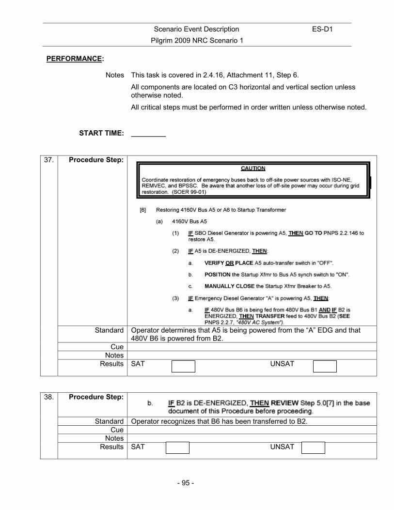
Notes This task is covered in 2.4.16, Attachment 11, Step 6.
All components are located on C3 horizontal and vertical section unless otherwise noted.
All critical steps must be performed in order written unless otherwise noted.
START TIME:
37. Procedure Step:
Standard Operator determines that A5 is being powered from the “A” EDG and that 480V B6 is powered from B2.
Cue Notes
Results SAT UNSAT
38. Procedure Step:
Standard Operator recognizes that B6 has been transferred to B2. Cue
Notes Results SAT UNSAT
Scenario Event Description ES-D1
Pilgrim 2009 NRC Scenario 1
- 96 -
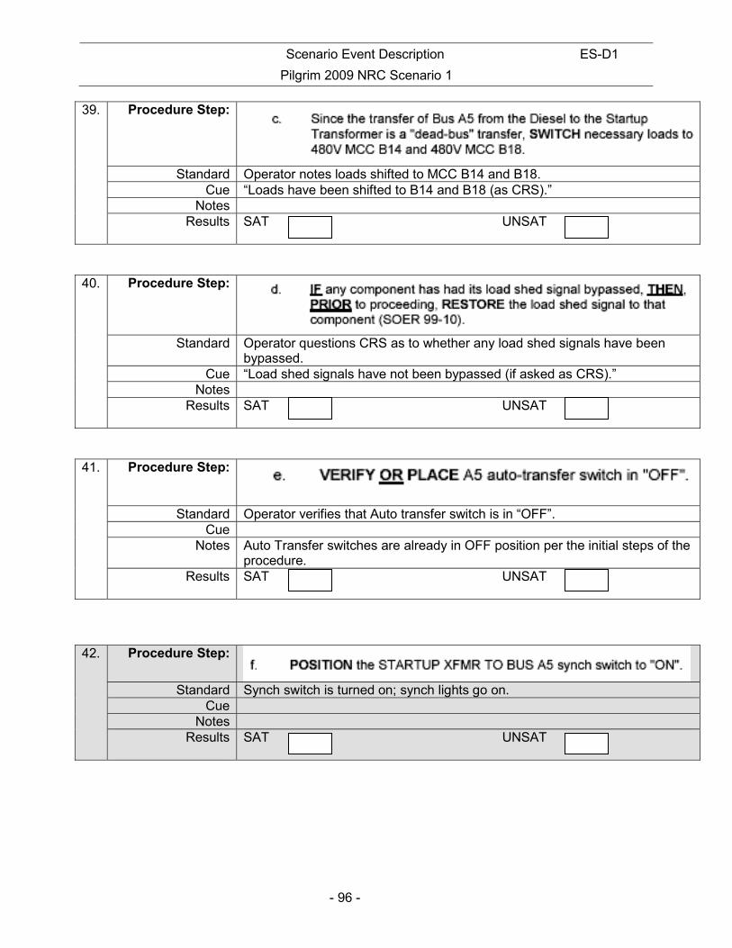
39. Procedure Step:
Standard Operator notes loads shifted to MCC B14 and B18. Cue “Loads have been shifted to B14 and B18 (as CRS).”
Notes Results SAT UNSAT
40. Procedure Step:
Standard Operator questions CRS as to whether any load shed signals have been bypassed.
Cue “Load shed signals have not been bypassed (if asked as CRS).” Notes
Results SAT UNSAT
41. Procedure Step:
Standard Operator verifies that Auto transfer switch is in “OFF”. Cue
Notes Auto Transfer switches are already in OFF position per the initial steps of the procedure.
Results SAT UNSAT
42. Procedure Step:
Standard Synch switch is turned on; synch lights go on. Cue
Notes Results SAT UNSAT

Scenario Event Description ES-D1
Pilgrim 2009 NRC Scenario 1
- 97 -
43. Procedure Step:
Standard A509 breaker is opened. Green light is on, red breaker light is off. Cue
Notes Results SAT UNSAT
44. Procedure Step: a. MANUALLY CLOSE the Startup Transformer to A5 bus after one second BUT before 4 seconds have elapsed. (The one second delay ensures a dead bus transfer; less than 4 seconds to prevent A509 reclosure.)
Standard Operator waits minimum of 1 second but not so long such that the EDG auto recloses back onto the bus (~ 4 seconds).
Cue Notes If bus is de-energized for 4 seconds then the EDG will auto reclose onto the
bus. Results SAT UNSAT
45. Procedure Step: VERIFY Bus A5 is ENERGIZED by observing bus VOLTAGE and bus AMP meters.
Standard Operator observes bus loading. Cue
Notes Results SAT UNSAT
46. Procedure Step: PLACE the STARTUP XFMR TO BUS A5 synch switch to OFF. Standard Operator turns synch switch off.
Cue Notes
Results SAT UNSAT

Scenario Event Description ES-D1
Pilgrim 2009 NRC Scenario 1
- 98 -
47. Procedure Step:
Standard Operator reports to the CRS that the Diesel Generator needs to be placed in standby.
Cue Another operator will perform that task Notes
Results SAT UNSAT
Cue: This completes this JPM.
STOP TIME: _______________________
Scenario Event Description ES-D1
Pilgrim 2009 NRC Scenario 1
- 99 -
INITIAL CONDITIONS:
• The plant had experienced a loss of off-site power
• Both EDGs are powering the emergency buses (A5 & A6)
• The Startup Transformer has been re-energized and buses A1 through A4 have been energized.
• The SM has determined that the grid is stable following discussions with REMVEC and the ISO.
• A field operator is standing by to support you in any required actions
• PNPS 2.4.16, ATT.11 ”Restoration Of AC Power” is complete through Step[5]
INITIATING CUE:
Restore power to the 4160VAC bus A-5 from the Startup Transformer per procedure 2.4.16, Attachment 11, starting at Step[6]”.
NUCLEAR PLANT OPERATOR JOB PERFORMANCE MEASURE

Scenario Event Description ES-D1
Pilgrim 2009 NRC Scenario 1
- 100 -
(RO/SRO) TITLE: TRANSFER PRESSURE REGULATION FROM MPR TO EPR WITH EPR
FAILURE ( ALTERNATE PATH ) OPERATOR:
DATE:
EVALUATOR:
EVALUATOR SIGNATURE:
CRITICAL TIME FRAME: Required Time (min): NA Actual Time (min): NA
PERFORMANCE TIME: Average Time (min): 15 Actual Time (min):
JPM RESULTS*: (Circle one) *Refer to Grading Instructions at end of JPM
SAT UNSAT NEEDS IMPROVEMENT
COMMENT SHEET ATTACHED: Yes / No (circle one) (Required for Unsat, Needs Improvement or Follow-Up Questions) SYNOPSIS:
With the reactor at full power, MHC pressure regulation is being controlled by the MPR following a failure of the EPR. Following repairs to the EPR, pressure regulation will be restored to the EPR. The operator will energize the EPR and place the EPR in service, when EPR is in service the EPR fails. Operator takes actions in accordance with 2.4.37.
TASK STANDARD:
The EPR will be energized and placed in service IAW 2.2.99. The procedure should be followed with no failure of critical elements. There will be no unacceptable pressure transients resulting from this transition (Rx scram, Bypass valve operation)
EVALUATION METHOD: EVALUATION LOCATION:
X Perform Plant
Simulate X Simulator
Control Room
Prepared: Date:
Reviewed: Date:
Approved: Superintendent, Operations Training (or Designee)
Date:

Scenario Event Description ES-D1
Pilgrim 2009 NRC Scenario 1
- 101 -
TASK Title: Task Number K&A SYSTEM: K&A RATING:
RESPOND TO EPR-MPR MALFUNCTION.
248-04-01-002
241000 A4.19 3.5/3.4
REFERENCES: PNPS 2.2.99, Rev.46 SIMULATOR CONDITIONS: 28. Initialize to full power IC 29. Transfer MHC pressure regulation to the MPR IAW 2.4.37. 30. Adjust MPR so that RPV pressure is within the prescribed band of 2.4.37. 31. Take EPR power to off 32. Pend EPR oscillation failure (UT1EP-TCO6 when H_A2_A1_M3_GT 936) 33. When MPR set point is raised the EPR will fail. GENERAL TOOLS AND EQUIPMENT: 4. None CRITICAL ELEMENTS: Critical elements are shaded in gray within the body of this document. OPERATOR BRIEF: 7. State the following paragraph IF this is the first performance in this setting:
a) “All actions associated with this job performance measure are to be performed. You will be provided access to any tools or equipment you determine necessary to perform the task. When a second checker is called for, the evaluator will perform the role of second checker and will always be in agreement with your actions. Before you start, the evaluator will state the task conditions and answer any questions, then provide a cue to begin”.
2. The task conditions are as follows:
i) The plant is at rated power
ii) Following a failure of the EPR, the MPR was placed in service IAW 2.4.37
iii) The EPR has been repaired
3. Solicit and answer any questions the operator may have.
Scenario Event Description ES-D1
Pilgrim 2009 NRC Scenario 1
- 102 -
INITIAL CONDITIONS:
• The plant is at rated power
• Following a failure of the EPR, the MPR was placed in service IAW 2.4.37
• The EPR has been repaired INITIATING CUE: IAW with 2.2.99, section 7.4.4, energize the EPR and restore pressure control to the EPR.
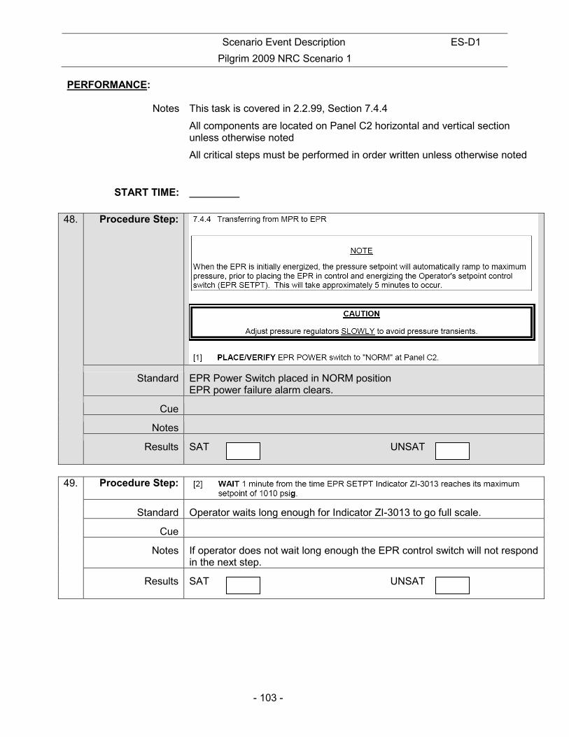
Scenario Event Description ES-D1
Pilgrim 2009 NRC Scenario 1
- 103 -
PERFORMANCE:
Notes This task is covered in 2.2.99, Section 7.4.4
All components are located on Panel C2 horizontal and vertical section unless otherwise noted
All critical steps must be performed in order written unless otherwise noted
START TIME:
48. Procedure Step:
Standard EPR Power Switch placed in NORM position EPR power failure alarm clears.
Cue
Notes
Results SAT UNSAT
49. Procedure Step:
Standard Operator waits long enough for Indicator ZI-3013 to go full scale.
Cue
Notes If operator does not wait long enough the EPR control switch will not respond in the next step.
Results SAT UNSAT

Scenario Event Description ES-D1
Pilgrim 2009 NRC Scenario 1
- 104 -
50. Procedure Step:
Standard Operator goes to LOWER on EPR control switch. Red “Press Control” light illuminates above the EPR setpoint switch.
Cue
Notes
Results SAT UNSAT
51. Procedure Step:
Standard Operator adjusts the MPR pressure setpoint to establish a deviation between 11 and 13%, with the EPR control position indicator being the higher of the two.
Cue
Notes
Results SAT UNSAT
52. Procedure Step:
Standard Operator adjusts EPR setpoint as required. PI-640-25A/B stable at a pressure of 1025 to 1045 psig
Cue
Notes
Results SAT UNSAT

Scenario Event Description ES-D1
Pilgrim 2009 NRC Scenario 1
- 105 -
53. Procedure Step:
Standard Operator recognizes the pressure oscillations when the EPR fails and enters 2.4.37
Cue
Notes If required the operator will lower core flow to obtain lee than or equal to 90% power
Results SAT UNSAT
54. Procedure Step:
Standard Operator reduces the MPR set point until the MPR takes control and takes the EPR control switch to OFF position.
Cue
Notes Operator takes EPR to off. This completes this JPM.
Results SAT UNSAT
STOP TIME:

Scenario Event Description ES-D1
Pilgrim 2009 NRC Scenario 1
- 106 -
INITIAL CONDITIONS:
• The plant is at rated power
• Following a failure of the EPR, the MPR was placed in service IAW 2.4.37
• The EPR has been repaired INITIATING CUE: IAW with 2.2.99, section 7.4.4, energize the EPR and restore pressure control to the EPR.

Scenario Event Description ES-D1
Pilgrim 2009 NRC Scenario 1
- 107 -
NUCLEAR PLANT OPERATOR JOB PERFORMANCE MEASURE (RO/SRO)
TITLE: Restoration of SDC LOOP A OPERATOR:
DATE:
EVALUATOR:
EVALUATOR SIGNATURE:
CRITICAL TIME FRAME: Required Time (min): N/A Actual Time (min): N/A
PERFORMANCE TIME: Average Time (min): 15 Actual Time (min):
JPM RESULTS*: (Circle one) *Refer to Grading Instructions at end of JPM
SAT UNSAT NEEDS IMPROVEMENT
COMMENT SHEET ATTACHED: Yes / No (circle one) (Required for Unsat, Needs Improvement or Follow-Up Questions) SYNOPSIS:
The reactor was shutdown four (4) hours ago. Shutdown cooling had already been established, but was terminated for testing purposes. The tests have been completed and ‘A’ loop RHR shutdown cooling needs to be re-established. When it is placed in service, a RHR leak will develop which should cause an auto PCIS isolation, however, the auto action doesn’t work and manual action is required by the operator to isolate the leak.
TASK STANDARD:
The ‘A’ loop of RHR is placed in shutdown cooling. RHR shall be operated in accordance with all applicable system precautions and limitations. When it is placed in service, a RHR leak will develop which requires manual operator action to isolate due to a PCIS failure. Procedure 2.2.19 shall be followed without deviation and with no failure of critical elements.
EVALUATION METHOD: EVALUATION LOCATION:
X Perform Plant
Simulate X Simulator
Control Room
Prepared: Date:
Reviewed: Date:
Approved: Superintendent, Operations Training (or Designee)
Date:

Scenario Event Description ES-D1
Pilgrim 2009 NRC Scenario 1
- 108 -
TASK Title: Task Number K&A SYSTEM: K&A RATING:
Restoration of SDC Loop A 205000 A4.02 3.6/3.5 REFERENCES: PNPS 2.2.19.1 Att.12 Examiners Note: PNPS 2.2.19.1 Rev 27, RESIDUAL HEAT REMOVAL SYSTEM-
SHUTDOWN COOLING MODE OF OPERATION includes a typographical error. Attachment 12 Section 2.0, step [4] incorrectly identifies the ‘C’ RHR Torus Suction Valve as ‘A’. The candidate will be provided with a corrected copy.
SIMULATOR CONDITIONS: 1. IC18 2. Secure Loop A SDC IAW PNPS 2.2.19.1 Att.12, Section 1.0 in its entirety. 3. Insert Malf. COP3, PCIS Group 3 Isolation Bypass. 4. Insert Malf RH05, Leak on RHR Pump A Disch Line at 4000 gpm. Condition malfunction on FI-1040-7. Greater than 1800 gpm. 5. Ensure MO-1001-29A, MO-1001-47 and MO-1001-50 are CLOSED. 6. Ensure Rector Water Level is > +30” and < +45” GENERAL TOOLS AND EQUIPMENT: NONE CRITICAL ELEMENTS: Critical elements are shaded in gray within the body of this document. OPERATOR BRIEF: 8. State the following paragraph IF this is the first performance in this setting:
a) “All actions associated with this job performance measure are to be performed. You will be provided access to any tools or equipment you determine necessary to perform the task. When a second checker is called for, the evaluator will perform the role of second checker and will always be in agreement with your actions. Before you start, the evaluator will state the task conditions and answer any questions, then provide a cue to begin”.
2. The task conditions are as follows:
• The reactor was shutdown four (4) hours ago. ‘A’ loop of RHR shutdown cooling needs to be re-established following a brief shutdown for testing.
3. Solicit and answer any questions the operator may have.

Scenario Event Description ES-D1
Pilgrim 2009 NRC Scenario 1
- 109 -
INITIAL CONDITIONS: The reactor was shutdown four (4) hours ago. ‘A’ loop of RHR shutdown cooling needs to be re-established following a brief shutdown for testing.
INITIATING CUE: Restore SDC using “A” RHR Pump IAW PNPS 2.2.19.1, Attachment 12, Section 2.0.

Scenario Event Description ES-D1
Pilgrim 2009 NRC Scenario 1
- 110 -
PERFORMANCE:
Notes
START TIME:
55. Procedure Step: [1] CLOSE/VERIFY CLOSED MO-1001-28A, LPCI Inj Throttle Vlv #1.
Standard Closes/verifies CLOSED MO-1001-28A, LPCI Inj Throttle Vlv #1. Cue
Notes Results SAT UNSAT
56. Procedure Step: [2] ENSURE an Operator is monitoring the Reactor water level.
Standard Ensures an Operator is monitoring the Reactor water level.
Cue Another operator is monitoring RPV Level Notes
Results SAT UNSAT
57. Procedure Step: [3] ISOLATE/VERIFY ISOLATED MO-1001-18A, RHR Pumps Loop A Minimum Flow Valve, control switch and breaker (B1754).
Standard Isolates/verifies ISOLATED MO-1001-18A, RHR Pumps Loop A Minimum Flow Valve, control switch and breaker (B1754).
Cue Notes MO-1001-18A position may be verified using Protective Tagging.
Results SAT UNSAT
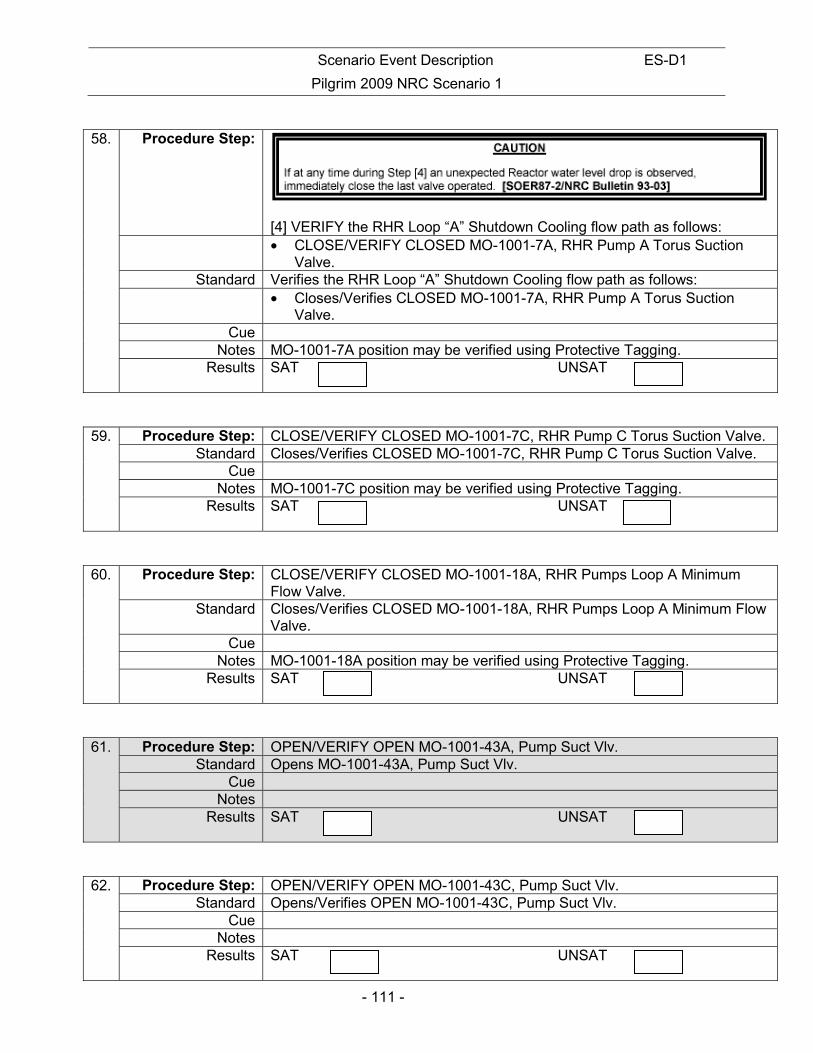
Scenario Event Description ES-D1
Pilgrim 2009 NRC Scenario 1
- 111 -
58. Procedure Step:
[4] VERIFY the RHR Loop “A” Shutdown Cooling flow path as follows: • CLOSE/VERIFY CLOSED MO-1001-7A, RHR Pump A Torus Suction
Valve. Standard Verifies the RHR Loop “A” Shutdown Cooling flow path as follows:
• Closes/Verifies CLOSED MO-1001-7A, RHR Pump A Torus Suction Valve.
Cue Notes MO-1001-7A position may be verified using Protective Tagging.
Results SAT UNSAT
59. Procedure Step: CLOSE/VERIFY CLOSED MO-1001-7C, RHR Pump C Torus Suction Valve. Standard Closes/Verifies CLOSED MO-1001-7C, RHR Pump C Torus Suction Valve.
Cue Notes MO-1001-7C position may be verified using Protective Tagging.
Results SAT UNSAT
60. Procedure Step: CLOSE/VERIFY CLOSED MO-1001-18A, RHR Pumps Loop A Minimum Flow Valve.
Standard Closes/Verifies CLOSED MO-1001-18A, RHR Pumps Loop A Minimum Flow Valve.
Cue Notes MO-1001-18A position may be verified using Protective Tagging.
Results SAT UNSAT
61. Procedure Step: OPEN/VERIFY OPEN MO-1001-43A, Pump Suct Vlv. Standard Opens MO-1001-43A, Pump Suct Vlv.
Cue Notes
Results SAT UNSAT
62. Procedure Step: OPEN/VERIFY OPEN MO-1001-43C, Pump Suct Vlv. Standard Opens/Verifies OPEN MO-1001-43C, Pump Suct Vlv.
Cue Notes
Results SAT UNSAT
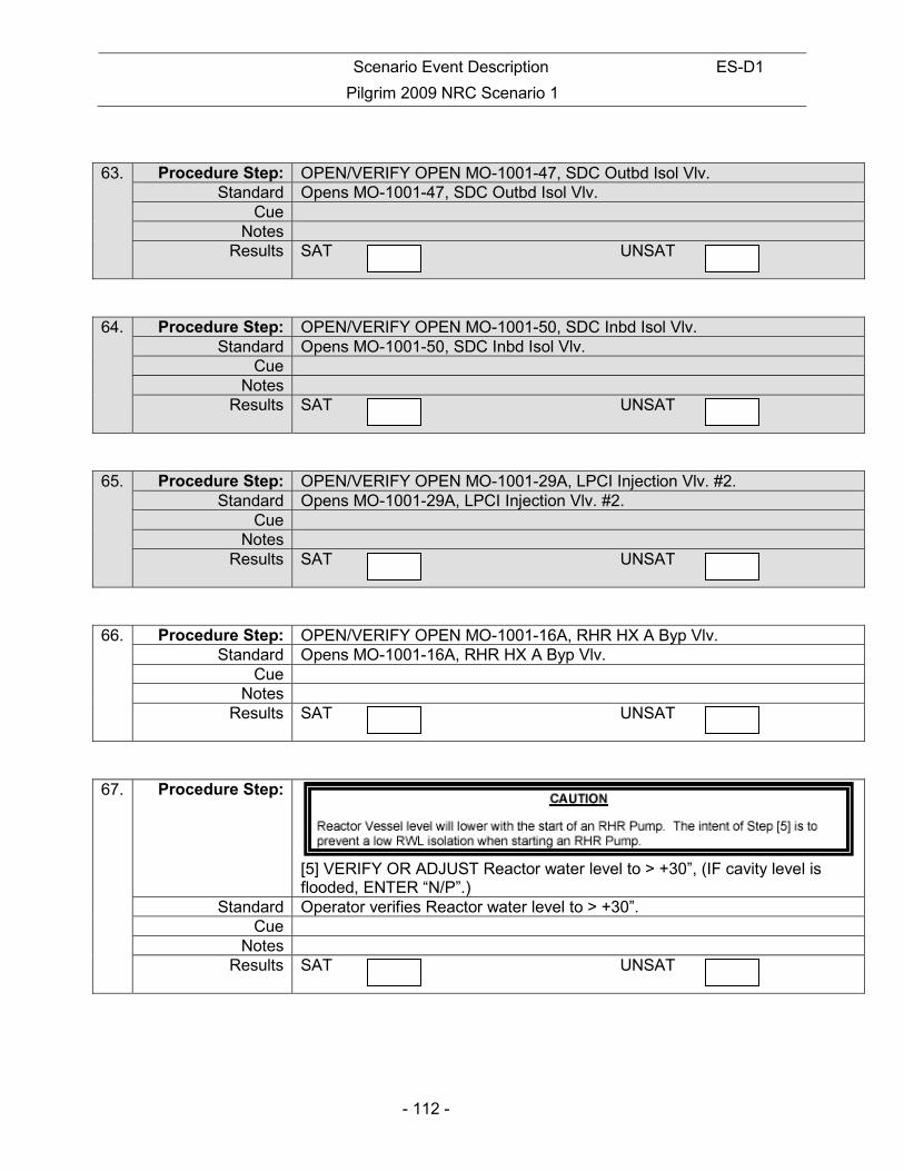
Scenario Event Description ES-D1
Pilgrim 2009 NRC Scenario 1
- 112 -
63. Procedure Step: OPEN/VERIFY OPEN MO-1001-47, SDC Outbd Isol Vlv. Standard Opens MO-1001-47, SDC Outbd Isol Vlv.
Cue Notes
Results SAT UNSAT
64. Procedure Step: OPEN/VERIFY OPEN MO-1001-50, SDC Inbd Isol Vlv. Standard Opens MO-1001-50, SDC Inbd Isol Vlv.
Cue Notes
Results SAT UNSAT
65. Procedure Step: OPEN/VERIFY OPEN MO-1001-29A, LPCI Injection Vlv. #2. Standard Opens MO-1001-29A, LPCI Injection Vlv. #2.
Cue Notes
Results SAT UNSAT
66. Procedure Step: OPEN/VERIFY OPEN MO-1001-16A, RHR HX A Byp Vlv. Standard Opens MO-1001-16A, RHR HX A Byp Vlv.
Cue Notes
Results SAT UNSAT
67. Procedure Step:
[5] VERIFY OR ADJUST Reactor water level to > +30”, (IF cavity level is flooded, ENTER “N/P”.)
Standard Operator verifies Reactor water level to > +30”. Cue
Notes Results SAT UNSAT

Scenario Event Description ES-D1
Pilgrim 2009 NRC Scenario 1
- 113 -
68. Procedure Step: [6] NOTIFY CRS to record in the CRS logbook the date and time RHR is placed into SDC mode. (a) NOTIFY Radiation Protection (RP) that RHR Pump A or C is about to be returned to service in the SDC mode. RP should monitor the “A” RHR Quadrant and the “A” Valve Room for radiological changes.
Standard Notifies CRS to record date and time RHR is placed in SDC in the CRS logbook. Notifies Radiation Protection (RP) that RHR Pump A or C is about to be returned to service in the SDC mode. RP should monitor the “A” RHR Quadrant and the “A” Valve Room for radiological changes.
Cue Notes
Results SAT UNSAT
69. Procedure Step:
Standard Reviews NOTE Cue
Notes Results SAT UNSAT
70. Procedure Step: [7] START an RHR pump by performing the following: (a) START RHR PUMP A OR C
Standard Starts A RHR Pump Cue
Notes Results SAT UNSAT
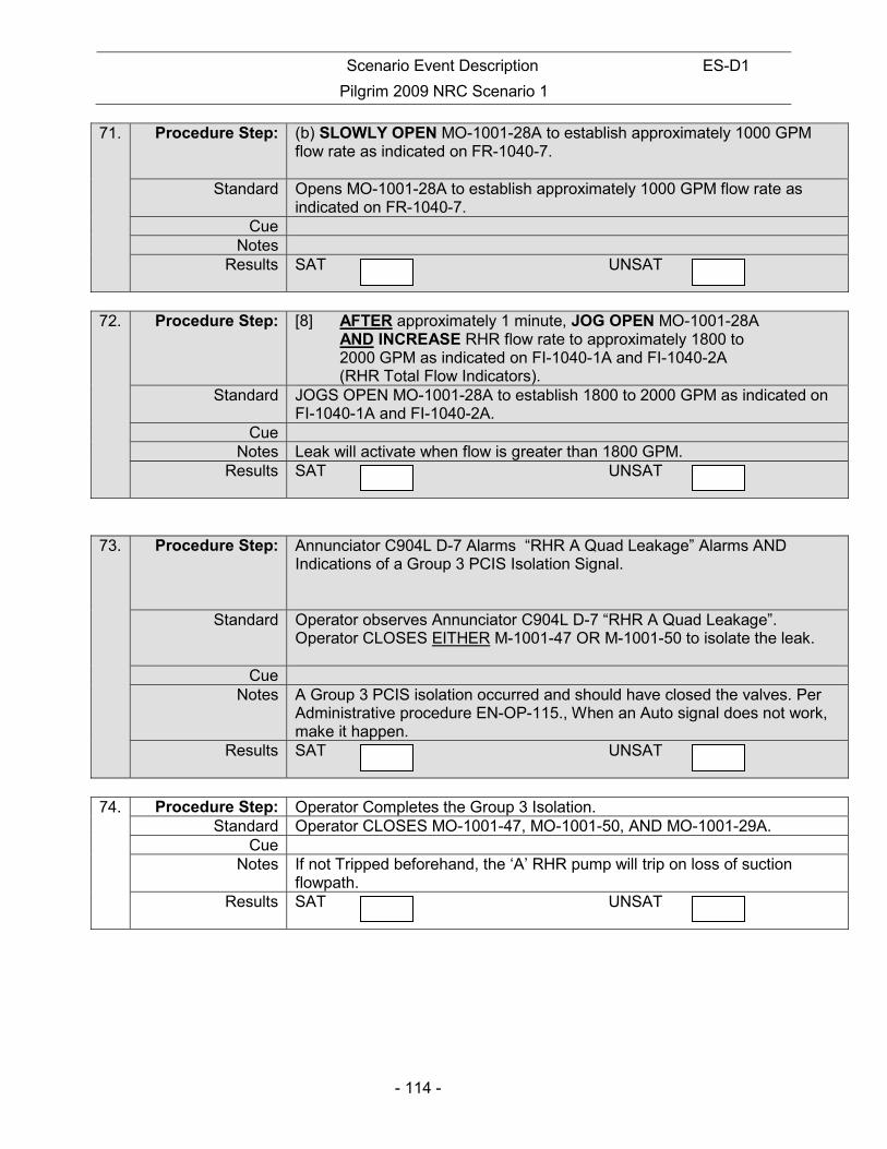
Scenario Event Description ES-D1
Pilgrim 2009 NRC Scenario 1
- 114 -
71. Procedure Step: (b) SLOWLY OPEN MO-1001-28A to establish approximately 1000 GPM flow rate as indicated on FR-1040-7.
Standard Opens MO-1001-28A to establish approximately 1000 GPM flow rate as indicated on FR-1040-7.
Cue Notes
Results SAT UNSAT
72. Procedure Step: [8] AFTER approximately 1 minute, JOG OPEN MO-1001-28A
AND INCREASE RHR flow rate to approximately 1800 to 2000 GPM as indicated on FI-1040-1A and FI-1040-2A (RHR Total Flow Indicators).
Standard JOGS OPEN MO-1001-28A to establish 1800 to 2000 GPM as indicated on FI-1040-1A and FI-1040-2A.
Cue Notes Leak will activate when flow is greater than 1800 GPM.
Results SAT UNSAT
73. Procedure Step: Annunciator C904L D-7 Alarms “RHR A Quad Leakage” Alarms AND Indications of a Group 3 PCIS Isolation Signal.
Standard Operator observes Annunciator C904L D-7 “RHR A Quad Leakage”. Operator CLOSES EITHER M-1001-47 OR M-1001-50 to isolate the leak.
Cue Notes A Group 3 PCIS isolation occurred and should have closed the valves. Per
Administrative procedure EN-OP-115., When an Auto signal does not work, make it happen.
Results SAT UNSAT
74. Procedure Step: Operator Completes the Group 3 Isolation.
Standard Operator CLOSES MO-1001-47, MO-1001-50, AND MO-1001-29A. Cue
Notes If not Tripped beforehand, the ‘A’ RHR pump will trip on loss of suction flowpath.
Results SAT UNSAT
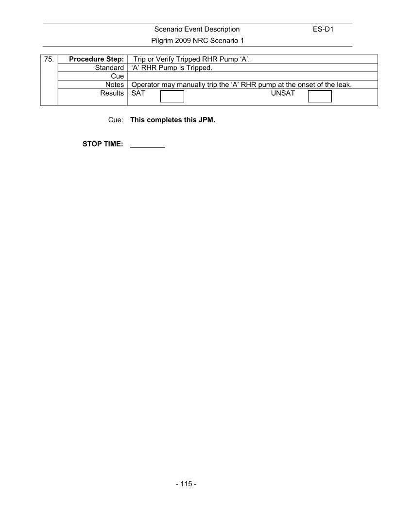
Scenario Event Description ES-D1
Pilgrim 2009 NRC Scenario 1
- 115 -
75. Procedure Step: Trip or Verify Tripped RHR Pump ‘A’. Standard ‘A’ RHR Pump is Tripped.
Cue Notes Operator may manually trip the ‘A’ RHR pump at the onset of the leak.
Results SAT UNSAT
Cue: This completes this JPM.
STOP TIME:
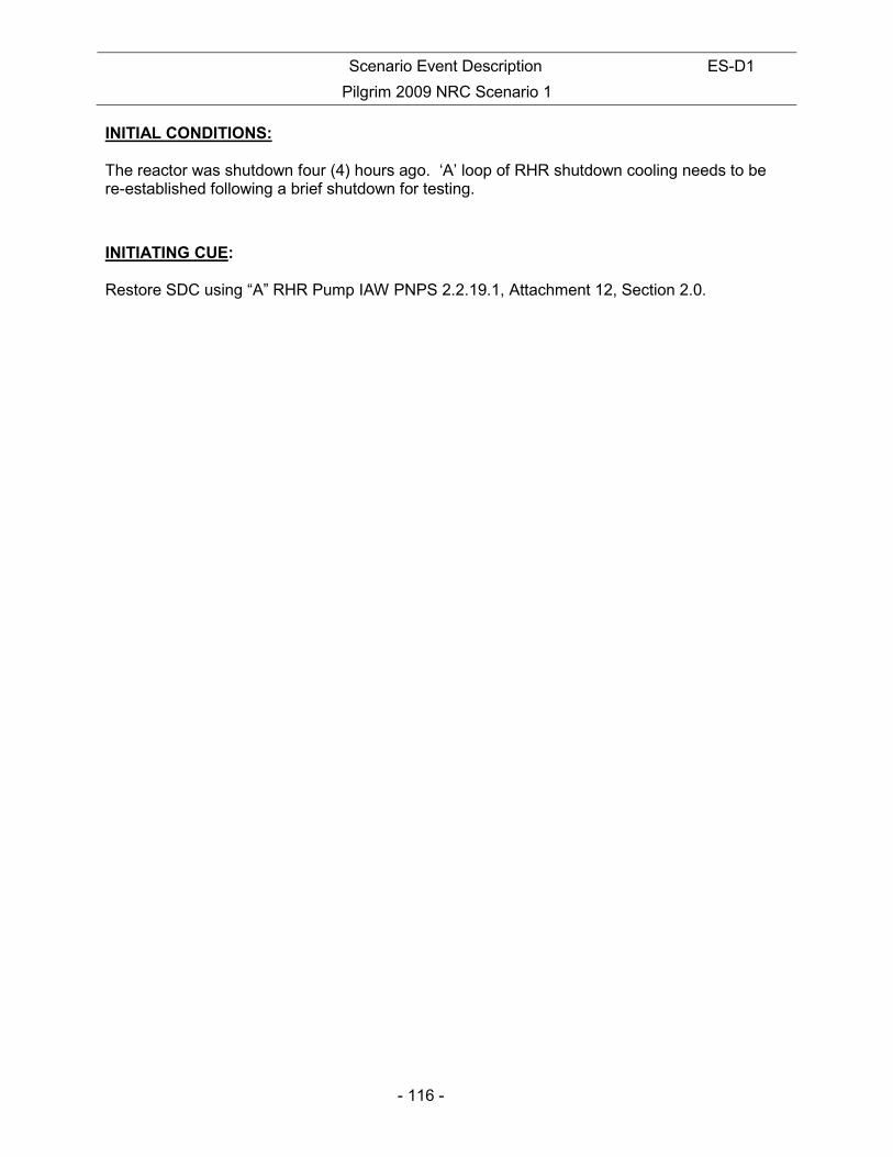
Scenario Event Description ES-D1
Pilgrim 2009 NRC Scenario 1
- 116 -
INITIAL CONDITIONS: The reactor was shutdown four (4) hours ago. ‘A’ loop of RHR shutdown cooling needs to be re-established following a brief shutdown for testing.
INITIATING CUE: Restore SDC using “A” RHR Pump IAW PNPS 2.2.19.1, Attachment 12, Section 2.0.
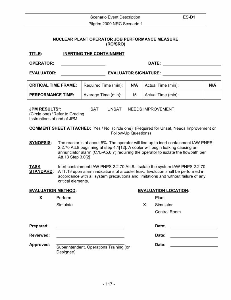
Scenario Event Description ES-D1
Pilgrim 2009 NRC Scenario 1
- 117 -
NUCLEAR PLANT OPERATOR JOB PERFORMANCE MEASURE
(RO/SRO) TITLE: INERTING THE CONTAINMENT OPERATOR:
DATE:
EVALUATOR:
EVALUATOR SIGNATURE:
CRITICAL TIME FRAME: Required Time (min): N/A Actual Time (min): N/A
PERFORMANCE TIME: Average Time (min): 15 Actual Time (min):
JPM RESULTS*: (Circle one) *Refer to Grading Instructions at end of JPM
SAT UNSAT NEEDS IMPROVEMENT
COMMENT SHEET ATTACHED: Yes / No (circle one) (Required for Unsat, Needs Improvement or Follow-Up Questions) SYNOPSIS:
The reactor is at about 5%. The operator will line up to inert containment IAW PNPS 2.2.70 Att.8 beginning at step 4.1[12]. A cooler will begin leaking causing an annunciator alarm (C7L-A5,6,7) requiring the operator to isolate the flowpath per Att.13 Step 3.0[2]
TASK STANDARD:
Inert containment IAW PNPS 2.2.70 Att.8. Isolate the system IAW PNPS 2.2.70 ATT.13 upon alarm indications of a cooler leak. Evolution shall be performed in accordance with all system precautions and limitations and without failure of any critical elements.
EVALUATION METHOD: EVALUATION LOCATION:
X Perform Plant
Simulate X Simulator
Control Room
Prepared: Date:
Reviewed: Date:
Approved: Superintendent, Operations Training (or Designee)
Date:

Scenario Event Description ES-D1
Pilgrim 2009 NRC Scenario 1
- 118 -
TASK Title: Task Number K&A SYSTEM: K&A RATING:
INERTING THE CONTAINMENT 223001 A4.10 3.2/3.2 REFERENCES: 1. PNPS 2.2.70 Att.8 & 13 SIMULATOR CONDITIONS: 34. IC with Reactor power at about 5% 35. PNPS 2.2.70 Att.8 complete thru Step 4.1[12] 3. At JPM Step 17 - Inserts Alarms:
• C7L-A5 and A6 ”Cooler NNN leaking “ • C904LC-B3 “C19A/B Trouble”
GENERAL TOOLS AND EQUIPMENT: 5. None CRITICAL ELEMENTS: Critical elements are shaded in gray within the body of this document. OPERATOR BRIEF: 9. State the following paragraph IF this is the first performance in this setting:
a) “All actions associated with this job performance measure are to be performed. You will be provided access to any tools or equipment you determine necessary to perform the task. When a second checker is called for, the evaluator will perform the role of second checker and will always be in agreement with your actions. Before you start, the evaluator will state the task conditions and answer any questions, then provide a cue to begin”.
2. The task conditions are as follows:
i) The reactor is at about 5% power
ii) Containment inerting preparations have started IAW PNPS 2.2.70 Att.8. The procedure is
complete through Step 4.1[12]
3. Solicit and answer any questions the operator may have.
Scenario Event Description ES-D1
Pilgrim 2009 NRC Scenario 1
- 119 -
INITIAL CONDITIONS:
• The reactor is at approximately 5% power • Containment inerting preparations have started IAW PNPS 2.2.70 Att.8. The procedure
is complete through Step 4.1[12] INITIATING CUE: Line up SGTS A train to inert containment IAW PNPS 2.2.70 Att.8 beginning at step 4.1[12].
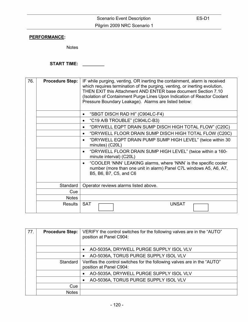
Scenario Event Description ES-D1
Pilgrim 2009 NRC Scenario 1
- 120 -
PERFORMANCE:
Notes
START TIME:
76. Procedure Step: IF while purging, venting, OR inerting the containment, alarm is received which requires termination of the purging, venting, or inerting evolution, THEN EXIT this Attachment AND ENTER base document Section 7.10 (Isolation of Containment Purge Lines Upon Indication of Reactor Coolant Pressure Boundary Leakage). Alarms are listed below:
• “SBGT DISCH RAD HI” (C904LC-F4)
• “C19 A/B TROUBLE” (C904LC-B3)
• “DRYWELL EQPT DRAIN SUMP DISCH HIGH TOTAL FLOW” (C20C)
• “DRYWELL FLOOR DRAIN SUMP DISCH HIGH TOTAL FLOW (C20C)
• “DRYWELL EQPT DRAIN PUMP SUMP HIGH LEVEL” (twice within 30 minutes) (C20L)
• “DRYWELL FLOOR DRAIN SUMP HIGH LEVEL” (twice within a 160-minute interval) (C20L)
• “COOLER ‘NNN’ LEAKING alarms, where ‘NNN’ is the specific cooler number (more than one unit in alarm) Panel C7L windows A5, A6, A7, B5, B6, B7, C5, and C6
Standard Operator reviews alarms listed above.
Cue Notes
Results SAT UNSAT
77. Procedure Step: VERIFY the control switches for the following valves are in the “AUTO” position at Panel C904:
• AO-5035A, DRYWELL PURGE SUPPLY ISOL VLV
• AO-5036A, TORUS PURGE SUPPLY ISOL VLV Standard Verifies the control switches for the following valves are in the “AUTO”
position at Panel C904:
• AO-5035A, DRYWELL PURGE SUPPLY ISOL VLV
• AO-5036A, TORUS PURGE SUPPLY ISOL VLV Cue
Notes

Scenario Event Description ES-D1
Pilgrim 2009 NRC Scenario 1
- 121 -
Results SAT UNSAT
78. Procedure Step: OPEN the following valves from Panel C7:
• AO-5042A, TORUS PURGE EXHAUSE ISOL VLV
• AO-5042B, TORUS PURGE EXHAUST ISOL VLV Standard Opens the following valves from Panel C7:
• AO-5042A, TORUS PURGE EXHAUSE ISOL VLV
• AO-5042B, TORUS PURGE EXHAUST ISOL VLV Cue
Notes Results SAT UNSAT
79. Procedure Step: VERIFY CLOSED AO-5035A, DRYWELL PURGE SUPPLY ISOL VLV, from Panel C7.
Standard Verifies Closed AO-5035A, DRYWELL PURGE SUPPLY ISOL VLV, from Panel C7.
Cue Notes
Results SAT UNSAT
80. Procedure Step: CLOSE the air supply block valve to AO-5035A, DRYWELL PURGE SUPPLY ISOL VLV, located in the Drywell personnel air lock access.
Standard Closes the air supply block valve to AO-5035A, DRYWELL PURGE SUPPLY ISOL VLV, located in the Drywell personnel air lock access.
Evaluator Operator: Candidate contacts Field Operator to close Valve.
Cue: Evaluator responds. Notes
Results SAT UNSAT
81. Procedure Step: VERIFY CLOSED AO-5035B, DRYWELL PURGE SUPPLY ISOL VLV.
Standard Verifies Closed AO-5035B, DRYWELL PURGE SUPPLY ISOL VLV.

Scenario Event Description ES-D1
Pilgrim 2009 NRC Scenario 1
- 122 -
Cue Notes
Results SAT UNSAT
82. Procedure Step: VERIFY CLOSED AO-5036B, TORUS PURGE SUPPLY ISOL VLV.
Standard Verifies Closed AO-5036B, TORUS PURGE SUPPLY ISOL VLV. Cue
Notes Results SAT UNSAT
83. Procedure Step: OPEN AO-5033B, DW/TORUS N2 PURGE ISOL VLV.
Standard Opens AO-5033B, DW/TORUS N2 PURGE ISOL VLV. Cue
Notes Results SAT UNSAT
84. Procedure Step: THROTTLE OPEN 9-HO-262, N2 Supply to Drywell/Torus Purge Block Valve. (Rx Bldg El. 23’)
Standard Throttles Open -HO-262, N2 Supply to Drywell/Torus Purge Block Valve.
Cue Candidate contacts Field Operator to open valve.
Evaluator Cue Evaluator responds as Field Operator that he opened the valve. Notes
Results SAT UNSAT
85. Procedure Step: OPEN 9-HO-117, Primary Cntmt Atm Control N2 Purge Supply Block Valve. (Drywell Access, Rx Bldg El. 23’)
Standard Opens 9-HO-117, Primary Cntmt Atm Control N2 Purge Supply Block Valve. Cue Candidate contacts Field Operator to open valve.
Evaluator’s Cue Responds as Field Operator that he opened the valve. Notes

Scenario Event Description ES-D1
Pilgrim 2009 NRC Scenario 1
- 123 -
Results SAT UNSAT
86. Procedure Step: VERIFY OPEN OR OPEN AO-N-98, Contaminated Exh to SGTS Inlet Plenum, as needed to maintain flow/pressure.
Standard Opens AO-N-98, Contaminated Exh to SGTS Inlet Plenum. Cue
Notes Results SAT UNSAT
87. Procedure Step: VERIFY OPEN OR OPEN AO-N-101, Refuel Floor Exh to SGTS Inlet Plenum, as needed to maintain flow/pressure.
Standard Opens AO-N-101, Refuel Floor Exh to SGTS Inlet Plenum. Cue
Notes Results SAT UNSAT
88. Procedure Step: AO-N-99, TRAIN A INLET DMPR, IS OPEN.
Standard AO-N-99, TRAIN A INLET DMPR, IS OPEN. Cue
Notes Results SAT UNSAT
89. Procedure Step: AO-N-108, TRAIN A OUTL DMPR, is OPEN.
Standard AO-N-108, TRAIN A OUTL DMPR, is OPEN. Cue
Notes Results SAT UNSAT

Scenario Event Description ES-D1
Pilgrim 2009 NRC Scenario 1
- 124 -
90. Procedure Step: VEX-210B, STANDBY GAS FAN B, is in “STANDBY”.
Standard VEX-210B, STANDBY GAS FAN B, is in “STANDBY”. Cue
Sim Booth Evaluator
Examiner’s Note Notes
Results SAT UNSAT
91. Procedure Step: START VEX-210A, STANDBY GAS FAN A, Panel C7 by placing the control switch in “RUN”
Standard STARTS VEX-210A, STANDBY GAS FAN A, Panel C7 by placing the control switch in “RUN”
Cue Sim Booth Evaluator
Examiner’s Note Applicant must now go to Attachment 13. Notes
Results SAT UNSAT
92. Procedure Step: Record the start time in the CRS LOG
Standard Records Start time in CRS LOG. Cue
Sim Booth Inserts Alarms: C7L-A5 and A6 ”Cooler NNN leaking “ C904LC-B3 “C19A/B Trouble”
Examiner’s Note Applicant must now go to Attachment 13. The Critical Portion of this step is responding to the alarms
Notes Results SAT UNSAT

Scenario Event Description ES-D1
Pilgrim 2009 NRC Scenario 1
- 125 -
93. Procedure Step: IAW Att.13 Steps 13[1] & [2]
IF, while venting, purging, or inerting the containment during power operation, any of the following alarms are received:
• “SBGT DISCH RAD HI” (C904LC-F4)
• “C19 A/B TROUBLE” (C904LC-B3)
• “DRYWELL EQPT DRAIN SUMP DISCH HIGH TOTAL FLOW” (C20C)
• “DRYWELL FLOOR DRAIN SUMP DISCH HIGH TOTAL FLOW” (C20C)
• “DRYWELL EQPT DRAIN PUMP SUMP HIGH LEVEL” (twice with 30 minutes) (C20L)
• “DRYWELL FLOOR DRAIN SUMP HIGH LEVEL” (twice within a 2-hour 40-minute interval) (C20L)
• “COOLER ‘NNN’ LEAKING” ALARMS, WHERE ‘NNN’ is the specific cooler number (more than one unit in alarm) Panel C7L windows A5, A6, A7, B5, B6, B7, C5, and C6
Standard Responds to Annunciators
Notes Annunciators above in BOLD will alarm Results SAT UNSAT
94. Procedure Step: CLOSES OR VERIFIES CLOSED SV-5030A, N2 Makeup Supply Block Valve.
Standard Closes SV-5030A, N2 Makeup Supply Block Valve. Cue
Notes Results SAT UNSAT
95. Procedure Step: CLOSES OR VERIFIES CLOSED AO-5035A, Drywell Purge Supply Isol Vlv.
Standard Closes AO-5035A, Drywell Purge Supply Isol Vlv. Cue
Notes Results SAT UNSAT
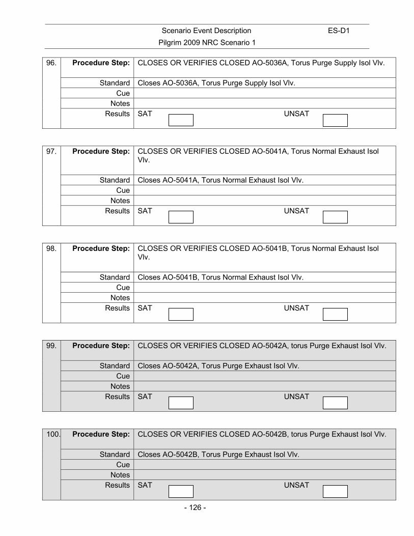
Scenario Event Description ES-D1
Pilgrim 2009 NRC Scenario 1
- 126 -
96. Procedure Step: CLOSES OR VERIFIES CLOSED AO-5036A, Torus Purge Supply Isol Vlv.
Standard Closes AO-5036A, Torus Purge Supply Isol Vlv. Cue
Notes Results SAT UNSAT
97. Procedure Step: CLOSES OR VERIFIES CLOSED AO-5041A, Torus Normal Exhaust Isol Vlv.
Standard Closes AO-5041A, Torus Normal Exhaust Isol Vlv. Cue
Notes Results SAT UNSAT
98. Procedure Step: CLOSES OR VERIFIES CLOSED AO-5041B, Torus Normal Exhaust Isol Vlv.
Standard Closes AO-5041B, Torus Normal Exhaust Isol Vlv. Cue
Notes Results SAT UNSAT
99. Procedure Step: CLOSES OR VERIFIES CLOSED AO-5042A, torus Purge Exhaust Isol Vlv.
Standard Closes AO-5042A, Torus Purge Exhaust Isol Vlv. Cue
Notes Results SAT UNSAT
100. Procedure Step: CLOSES OR VERIFIES CLOSED AO-5042B, torus Purge Exhaust Isol Vlv.
Standard Closes AO-5042B, Torus Purge Exhaust Isol Vlv. Cue
Notes Results SAT UNSAT

Scenario Event Description ES-D1
Pilgrim 2009 NRC Scenario 1
- 127 -
101. Procedure Step: CLOSES OR VERIFIES CLOSED AO-5043A, Drywell Normal Exhaust Isol Vlv.
Standard Closes AO-5043A, Drywell Normal Exhaust Isol Vlv. Cue
Notes Results SAT UNSAT
102. Procedure Step: CLOSES OR VERIFIES CLOSED AO-5043B, Drywell Normal Exhaust Isol Vlv.
Standard Closes AO-5043B, Drywell Normal Exhaust Isol Vlv. Cue
Notes Results SAT UNSAT
103. Procedure Step: CLOSES OR VERIFIES CLOSED AO-5044A, Drywell Purge Exhaust Isol Vlv.
Standard Closes AO-5044A, Drywell Purge Exhaust Isol Vlv. Cue
Notes Results SAT UNSAT
104. Procedure Step: CLOSES OR VERIFIES CLOSED AO-5044B, Drywell Purge Exhaust Isol Vlv.
Standard Closes AO-5044B, Drywell Purge Exhaust Isol Vlv. Cue
Notes Results SAT UNSAT

Scenario Event Description ES-D1
Pilgrim 2009 NRC Scenario 1
- 128 -
105. Procedure Step: IF “A” SGTS was running, THEN at Panel C7, PLACE control switch for
VEX-210A, Standby Gas Fan A, to “AUTO”.
Standard Places control switch for VEX-210A, Standby Gas Fan A, to “AUTO”. Cue
Notes Results SAT UNSAT
106. Procedure Step: IF “B” SGTS was running, THEN at Panel C7, PLACE control switch for AO-N-106, Train B Inlet Dmpr, to “AUTO”.
Standard N/A – B was not running Cue
Notes Results SAT UNSAT
107. Procedure Step: VERIFY OR PLACE the following dampers into the “AUTO” position:
• AO-N-99, Train A Inlet Dmpr
• AO-N-108, Train A Outl Dmpr
• AO-N-112, Train B Outl Dmpr Standard Places the following dampers into the “AUTO” position:
• AO-N-99, Train A Inlet Dmpr
• AO-N-108, Train A Outl Dmpr
• AO-N-112, Train B Outl Dmpr Cue
Notes Results SAT UNSAT
CUE: JPM is complete
STOP TIME:

Scenario Event Description ES-D1
Pilgrim 2009 NRC Scenario 1
- 129 -
INITIAL CONDITIONS:
• The reactor is at approximately 5% power • Containment inerting preparations have started IAW PNPS 2.2.70 Att.8. The procedure
is complete through Step 4.1[12] INITIATING CUE: Line up SGTS A train to inert containment IAW PNPS 2.2.70 Att.8 beginning at step 4.1[12].

Scenario Event Description ES-D1
Pilgrim 2009 NRC Scenario 1
- 130 -
NUCLEAR PLANT OPERATOR JOB PERFORMANCE MEASURE
(RO/SRO) TITLE: RECOVER RBCCW LOOP ‘B’ WITH AN ELEVATED DRYWELL TEMPERATURE OPERATOR:
DATE:
EVALUATOR:
EVALUATOR SIGNATURE:
CRITICAL TIME FRAME: Required Time (min): N/A Actual Time (min): N/A
PERFORMANCE TIME: Average Time (min): 20 Actual Time (min):
JPM RESULTS*: (Circle one) *Refer to Grading Instructions at end of JPM
SAT UNSAT NEEDS IMPROVEMENT
COMMENT SHEET ATTACHED: Yes / No (circle one) (Required for Unsat, Needs Improvement or Follow-Up Questions) SYNOPSIS:
A non-LOCA event occurred that caused a reactor scram. Subsequent power and equipment failures have rendered RBCCW Loop ‘B’ inoperable, causing drywell temperature to exceed 250°F. Electrical faults have been corrected, and it is desired to restore RBCCW Loop ‘B’ system flow.
TASK STANDARD:
The RBCCW Loop ‘B’ will be restored without causing condensation-induced water hammer due to elevated drywell temperature. Procedure 2.4.42 shall be carried out without failure of any critical elements.
EVALUATION METHOD: EVALUATION LOCATION:
X Perform Plant
Simulate X Simulator
Control Room
Prepared: Date:
Reviewed: Date:
Approved: Superintendent, Operations Training (or Designee)
Date:

Scenario Event Description ES-D1
Pilgrim 2009 NRC Scenario 1
- 131 -
TASK Title: Task Number K&A SYSTEM: K&A RATING:
Respond to High Drywell Temperature (EOP-03)
200-05-01-021 400000 AA4.01 3.1/3.2
REFERENCES: PNPS 2.4.42 SIMULATOR CONDITIONS: 36. Initialize to any at power IC 37. Place HPCI Aux. Oil Pump in PTL. 38. Place all Loop “B” RBCCW Pumps in PTL 39. When the Reactor Scrams, carry out PNPS 2.1.6 40. Stabilize RPV Pressure and Level 41. Allow Drywell Temperature to rise to greater than 250 degrees GENERAL TOOLS AND EQUIPMENT: None CRITICAL ELEMENTS: Critical elements are shaded in gray within the body of this document. OPERATOR BRIEF: 10. State the following paragraph IF this is the first performance in this setting:
a) “All actions associated with this job performance measure are to be performed. You will be provided access to any tools or equipment you determine necessary to perform the task. When a second checker is called for, the evaluator will perform the role of second checker and will always be in agreement with your actions. Before you start, the evaluator will state the task conditions and answer any questions, then provide a cue to begin”.
2. The task conditions are as follows:
i) A loss of B14 has occurred resulting in a loss of “B” loop RBCCW pumps
ii) RBCCW could not be cross-tied due to the inability to open a cross connect valve.
iii) The HPCI Aux Oil Pump is in PTL.
iv) The reactor was scrammed and the actions of PNPS 2.1.6 carried out.
v) EOP-03 has been entered on high drywell temperature
vi) The fault on B-14 has been cleared
vii) SSW pumps have been started IAW PNPS 2.4.43
viii) “B” Loop RBCCW pumps are in PTL in preparation for restoring B14 IAW 2.4.42.
ix) Drywell temperature has exceeded 250 degrees for the past 8 minutes

Scenario Event Description ES-D1
Pilgrim 2009 NRC Scenario 1
- 132 -
3. Solicit and answer any questions the operator may have.
INITIAL CONDITIONS:
• A loss of B14 has occurred resulting in a loss of “B” loop RBCCW pumps
• RBCCW could not be cross-tied due to the inability to open a cross connect valve.
• The HPCI Aux Oil Pump is in PTL.
• The reactor was scrammed and the actions of PNPS 2.1.6 carried out.
• EOP-03 has been entered on high drywell temperature
• The fault on B-14 has been cleared
• SSW pumps have been started IAW PNPS 2.4.43
• “B” Loop RBCCW pumps are in PTL in preparation for restoring B14 IAW 2.4.42.
• Drywell temperature has exceeded 250 degrees for the past 8 minutes
INITIATING CUE:
B14 has been re-energized. Restore RBCCW Loop ‘B’ IAW PNPS 2.4.42 Section 4.2. Inform me when you have completed the task.

Scenario Event Description ES-D1
Pilgrim 2009 NRC Scenario 1
- 133 -
PERFORMANCE:
Notes This task is covered in 2.4.42, Section 4.2.
All critical steps must be performed in order written unless otherwise noted.
START TIME:
108. Procedure Step:
Standard Operator enters Step 3 of the procedure. Cue
Notes Initial Conditions described Non-LOCA conditions. Results SAT UNSAT

Scenario Event Description ES-D1
Pilgrim 2009 NRC Scenario 1
- 134 -
109. Procedure Step: [3] IF ALL of the following conditions exist:
• NO indications of a major LOCA inside Primary Containment; • Drywell temperature has been >250F; • RBCCW flow has been lost to the Drywell for >6 minutes; THEN RECOVER RBCCW Loop “B” as directed in the following steps:
(a)CLOSE the following RBCCW Loop “B” Nonessential Isolation Valves at Panel C1:
• MO-4009A, RBCCW Loop “B” Nonessential Loop Inlet Valve • MO-4009B, RBCCW Loop “B” Nonessential Loop Outlet Valve
Standard Operator closes MO-4009A & B. Both valves indicate closed as evidenced
by red light off & green light on. Cue
Notes Results SAT UNSAT
110. Procedure Step:
(b) START one “B” RBCCW loop pump OR CROSS-TIE RBCCW loops in accordance with Attachment 5.
Standard Operator starts one RBCCW pump. Red light on and green light off, and pressure increase on PI-4008 Panel C-1.
Cue IF the Operator requests a Field Operator be dispatched to the “B” Auxiliary Bay for the pump start, as CRS respond, “No Field Operators are available.”
Notes Results SAT UNSAT
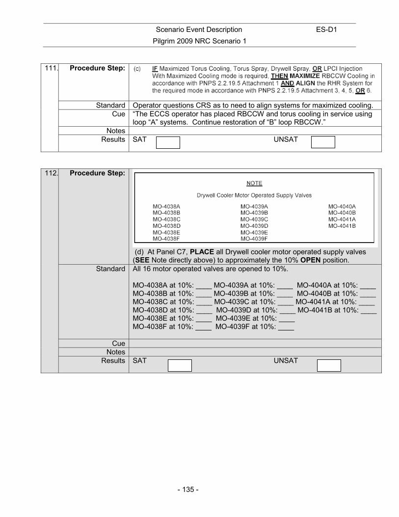
Scenario Event Description ES-D1
Pilgrim 2009 NRC Scenario 1
- 135 -
111. Procedure Step:
Standard Operator questions CRS as to need to align systems for maximized cooling. Cue “The ECCS operator has placed RBCCW and torus cooling in service using
loop “A” systems. Continue restoration of “B” loop RBCCW.” Notes
Results SAT UNSAT
112. Procedure Step:
(d) At Panel C7, PLACE all Drywell cooler motor operated supply valves (SEE Note directly above) to approximately the 10% OPEN position.
Standard All 16 motor operated valves are opened to 10%. MO-4038A at 10%: ____ MO-4039A at 10%: ____ MO-4040A at 10%: ____ MO-4038B at 10%: ____ MO-4039B at 10%: ____ MO-4040B at 10%: ____ MO-4038C at 10%: ____ MO-4039C at 10%: ____ MO-4041A at 10%: ____ MO-4038D at 10%: ____ MO-4039D at 10%: ____ MO-4041B at 10%: ____ MO-4038E at 10%: ____ MO-4039E at 10%: ____ MO-4038F at 10%: ____ MO-4039F at 10%: ____
Cue Notes
Results SAT UNSAT

Scenario Event Description ES-D1
Pilgrim 2009 NRC Scenario 1
- 136 -
113. Procedure Step: (e) OPEN the following RBCCW Loop “B” Nonessential Isolation Valves at Panel C1:
• MO-4009A, RBCCW Loop “B” Nonessential Loop Inlet Valve • MO-4009B, RBCCW Loop “B” Nonessential Loop Outlet Valve
Standard MO-4009A and B are opened. Red light on/green light off. Cue
Notes Results SAT UNSAT
114. Procedure Step: (f) OPEN all Drywell cooler supply MOV’s [SEE Note above Step (d)].
Standard All 16 motor operated valves are opened to 100%. MO-4038A at 100%: ___ MO-4039A at 100%: ___ MO-4040A at 100%: ___MO-4038B at 100%: ___ MO-4039B at 100%: ___ MO-4040B at 100%: ___MO-4038C at 100%: ___ MO-4039C at 100%: ___ MO-4041A at 100%: ___ MO-4038D at 100%: ___ MO-4039D at 100%: ___ MO-4041B at 100%: ___ MO-4038E at 100%: ___ MO-4039E at 100%: ___ MO-4038F at 100%: ___ MO-4039F at 100%: ___
Cue Notes
Results SAT UNSAT

Scenario Event Description ES-D1
Pilgrim 2009 NRC Scenario 1
- 137 -
115. Procedure Step:
Standard Operator determines that there is no break in RBCCW cooling piping in D/W. Cue Role Play as required to provide indication that RBCCW loop “B” has not
been breached if operator requests information from field Notes The operator can make this determination in several ways, including the
following: Operator can use steady pressure indication on RBCCW loop “B” and /or Absence of RBCCW loop “B” surge tank alarm and/or Request field operator to verify steady surge tank level. Etc. .
Results SAT UNSAT
116. Procedure Step:
Standard Cue “This concludes the JPM.”
Notes Results SAT UNSAT
STOP TIME:

Scenario Event Description ES-D1
Pilgrim 2009 NRC Scenario 1
- 138 -
INITIAL CONDITIONS:
• A loss of B14 has occurred resulting in a loss of “B” loop RBCCW pumps
• RBCCW could not be cross-tied due to the inability to open a cross connect valve.
• The HPCI Aux Oil Pump is in PTL.
• The reactor was scrammed and the actions of PNPS 2.1.6 carried out.
• EOP-03 has been entered on high drywell temperature
• The fault on B-14 has been cleared
• SSW pumps have been started IAW PNPS 2.4.43
• “B” Loop RBCCW pumps are in PTL in preparation for restoring B14 IAW 2.4.42.
• Drywell temperature has exceeded 250 degrees for the past 8 minutes
INITIATING CUE:
B14 has been re-energized. Restore RBCCW Loop ‘B’ IAW PNPS 2.4.42 Section 4.2. Inform me when you have completed the task.
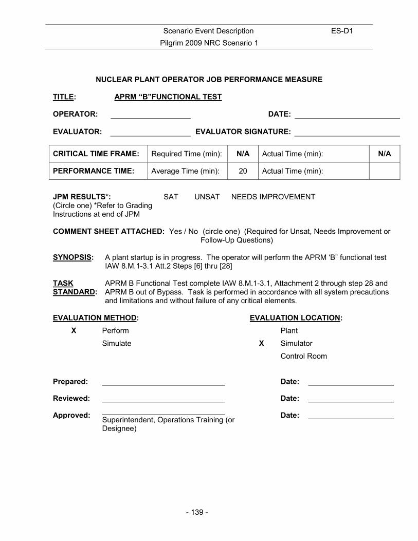
Scenario Event Description ES-D1
Pilgrim 2009 NRC Scenario 1
- 139 -
NUCLEAR PLANT OPERATOR JOB PERFORMANCE MEASURE TITLE: APRM “B”FUNCTIONAL TEST OPERATOR:
DATE:
EVALUATOR:
EVALUATOR SIGNATURE:
CRITICAL TIME FRAME: Required Time (min): N/A Actual Time (min): N/A
PERFORMANCE TIME: Average Time (min): 20 Actual Time (min):
JPM RESULTS*: (Circle one) *Refer to Grading Instructions at end of JPM
SAT UNSAT NEEDS IMPROVEMENT
COMMENT SHEET ATTACHED: Yes / No (circle one) (Required for Unsat, Needs Improvement or Follow-Up Questions) SYNOPSIS:
A plant startup is in progress. The operator will perform the APRM ‘B” functional test IAW 8.M.1-3.1 Att.2 Steps [6] thru [28]
TASK STANDARD:
APRM B Functional Test complete IAW 8.M.1-3.1, Attachment 2 through step 28 and APRM B out of Bypass. Task is performed in accordance with all system precautions and limitations and without failure of any critical elements.
EVALUATION METHOD: EVALUATION LOCATION:
X Perform Plant
Simulate X Simulator
Control Room
Prepared: Date:
Reviewed: Date:
Approved: Superintendent, Operations Training (or Designee)
Date:
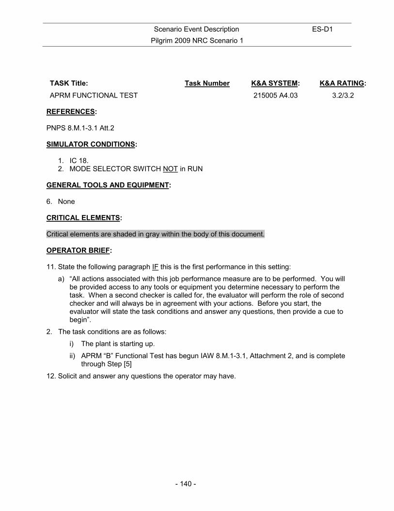
Scenario Event Description ES-D1
Pilgrim 2009 NRC Scenario 1
- 140 -
TASK Title: Task Number K&A SYSTEM: K&A RATING:
APRM FUNCTIONAL TEST 215005 A4.03 3.2/3.2 REFERENCES: PNPS 8.M.1-3.1 Att.2 SIMULATOR CONDITIONS:
1. IC 18. 2. MODE SELECTOR SWITCH NOT in RUN
GENERAL TOOLS AND EQUIPMENT: 6. None CRITICAL ELEMENTS: Critical elements are shaded in gray within the body of this document. OPERATOR BRIEF: 11. State the following paragraph IF this is the first performance in this setting:
a) “All actions associated with this job performance measure are to be performed. You will be provided access to any tools or equipment you determine necessary to perform the task. When a second checker is called for, the evaluator will perform the role of second checker and will always be in agreement with your actions. Before you start, the evaluator will state the task conditions and answer any questions, then provide a cue to begin”.
2. The task conditions are as follows:
i) The plant is starting up.
ii) APRM “B” Functional Test has begun IAW 8.M.1-3.1, Attachment 2, and is complete through Step [5]
12. Solicit and answer any questions the operator may have.

Scenario Event Description ES-D1
Pilgrim 2009 NRC Scenario 1
- 141 -
INITIAL CONDITIONS:
• A plant startup is in progress
• APRM “B” Functional Test has begun IAW 8.M.1-3.1, Attachment 2, and is complete through Step [5]
INITIATING CUE: Perform APRM “B” Functional Test in accordance with 8.M.1-3.1, Attachment 2. Begin at procedure Step [6].

Scenario Event Description ES-D1
Pilgrim 2009 NRC Scenario 1
- 142 -
PERFORMANCE:
Notes
START TIME:
117. Procedure Step: VERIFY the APRM “B” BYPASS indication lights at Panels C905 and C937 are ON.
Standard Verifies the APRM “B” BYPASS indication lights at Panels C905 and C937 are ON.
Cue Notes
Results SAT UNSAT
118. Procedure Step: VERIFY the following:
• The SET DOWN white light for APRM “B” channel at Panel C937 is ON.
• CRD Scram Solenoid Group 1-4 lights at Panels C915 and C917 are ON. Standard Verifies the following:
• The SET DOWN white light for APRM “B” channel at Panel C937 is ON.
• CRD Scram Solenoid Group 1-4 lights at Panels C915 and C917 are ON. Cue
Notes Results SAT UNSAT
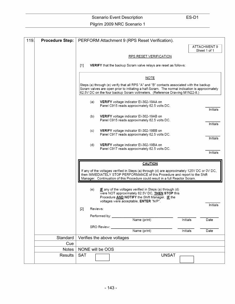
Scenario Event Description ES-D1
Pilgrim 2009 NRC Scenario 1
- 143 -
119. Procedure Step: PERFORM Attachment 9 (RPS Reset Verification).
Standard Verifies the above voltages Cue
Notes NONE will be OOS Results SAT UNSAT
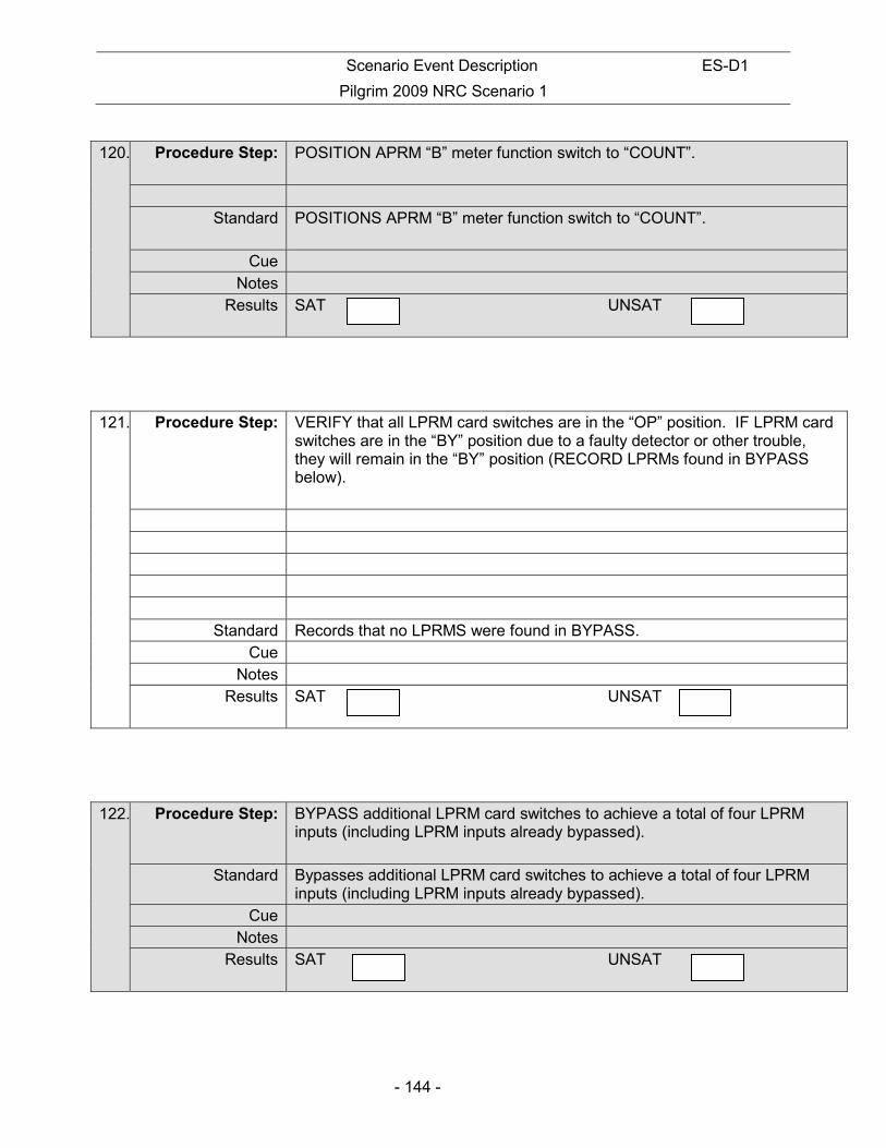
Scenario Event Description ES-D1
Pilgrim 2009 NRC Scenario 1
- 144 -
120. Procedure Step: POSITION APRM “B” meter function switch to “COUNT”.
Standard POSITIONS APRM “B” meter function switch to “COUNT”.
Cue Notes
Results SAT UNSAT
121. Procedure Step: VERIFY that all LPRM card switches are in the “OP” position. IF LPRM card switches are in the “BY” position due to a faulty detector or other trouble, they will remain in the “BY” position (RECORD LPRMs found in BYPASS below).
Standard Records that no LPRMS were found in BYPASS. Cue
Notes Results SAT UNSAT
122. Procedure Step: BYPASS additional LPRM card switches to achieve a total of four LPRM inputs (including LPRM inputs already bypassed).
Standard Bypasses additional LPRM card switches to achieve a total of four LPRM inputs (including LPRM inputs already bypassed).
Cue Notes
Results SAT UNSAT

Scenario Event Description ES-D1
Pilgrim 2009 NRC Scenario 1
- 145 -
123. Procedure Step: VERIFY APRM “B” local INOP light is ON AND APRM “B” meter indicates correct number of operable LPRM inputs. RECORD value below:
Standard Verifies APRM “B” local INOP light is ON AND APRM “B” meter indicates correct number of operable LPRM inputs.
Cue Candidate records value of 50%. Notes
Results SAT UNSAT
124. Procedure Step: RETURN previously selected LPRM card switches to the “OPERATE” position observing the instruction in Step [9] above.
Standard Returns previously selected LPRM card switches to the “OPERATE” position observing the instruction in Step [9]
Cue Notes
Results SAT UNSAT
125. Procedure Step: ACTUATE trip reset switch on APRM “B”.
Standard Actuates the trip reset switch for APRM “B”.
Cue Notes
Results SAT UNSAT
126. Procedure Step: VERIFY APRM “B” local INOP light is OFF.
Standard Verifies APRM “B” local INOP light is OFF. Cue
Notes Results SAT UNSAT
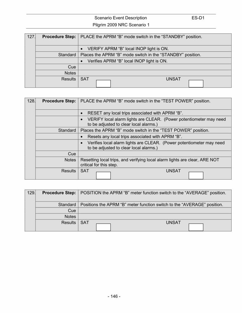
Scenario Event Description ES-D1
Pilgrim 2009 NRC Scenario 1
- 146 -
127. Procedure Step: PLACE the APRM “B” mode switch in the “STANDBY” position.
• VERIFY APRM “B” local INOP light is ON. Standard Places the APRM “B” mode switch in the “STANDBY” position.
• Verifies APRM “B” local INOP light is ON. Cue
Notes Results SAT UNSAT
128. Procedure Step: PLACE the APRM “B” mode switch in the “TEST POWER” position.
• RESET any local trips associated with APRM “B”.
• VERIFY local alarm lights are CLEAR. (Power potentiometer may need to be adjusted to clear local alarms.)
Standard Places the APRM “B” mode switch in the “TEST POWER” position.
• Resets any local trips associated with APRM “B”.
• Verifies local alarm lights are CLEAR. (Power potentiometer may need to be adjusted to clear local alarms.)
Cue Notes Resetting local trips, and verifying local alarm lights are clear, ARE NOT
critical for this step. Results SAT UNSAT
129. Procedure Step: POSITION the APRM “B” meter function switch to the “AVERAGE” position.
Standard Positions the APRM “B” meter function switch to the “AVERAGE” position. Cue
Notes Results SAT UNSAT

Scenario Event Description ES-D1
Pilgrim 2009 NRC Scenario 1
- 147 -
130. Procedure Step: ADJUST the APRM “B” POWER potentiometer until the HIGH light comes on indicating the value of power signal that will initiate a rod block function.
Standard Adjusts the APRM “B” POWER potentiometer until the HIGH light comes on indicating the value of power signal that will initiate a rod block function.
Cue Notes
Results SAT UNSAT
131. Procedure Step: RECORD the “As-Found” value of power. The setpoint for the HIGH or rod block function is 11 (10.5 to 11.5) percent power.
Standard Records the “As-Found” value of power. The setpoint for the HIGH or rod block function is 11 (10.5 to 11.5) percent power.
Cue Notes
Results SAT UNSAT
132. Procedure Step: ADJUST the APRM “B” POWER potentiometer until the HIGH-HIGH light comes on indicating the value of power signal that will initiate a Scram function.
Standard Adjust the APRM “B” Power potentiometer until the HIGH-HIGH light comes on indicating the value of power signal that will initiate a Scram function.
Cue Notes
Results SAT UNSAT
133. Procedure Step: RECORD the “As-Found” value of power. The setpoint for the HIGH-HIGH or Scram function is 13 (12.5 to 13.5) percent power.
Standard Records the “As-Found” value of power. Cue
Notes Results SAT UNSAT
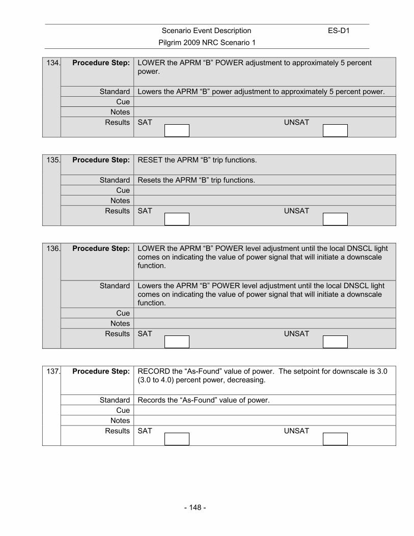
Scenario Event Description ES-D1
Pilgrim 2009 NRC Scenario 1
- 148 -
134. Procedure Step: LOWER the APRM “B” POWER adjustment to approximately 5 percent power.
Standard Lowers the APRM “B” power adjustment to approximately 5 percent power. Cue
Notes Results SAT UNSAT
135. Procedure Step: RESET the APRM “B” trip functions.
Standard Resets the APRM “B” trip functions. Cue
Notes Results SAT UNSAT
136. Procedure Step: LOWER the APRM “B” POWER level adjustment until the local DNSCL light comes on indicating the value of power signal that will initiate a downscale function.
Standard Lowers the APRM “B” POWER level adjustment until the local DNSCL light comes on indicating the value of power signal that will initiate a downscale function.
Cue Notes
Results SAT UNSAT
137. Procedure Step: RECORD the “As-Found” value of power. The setpoint for downscale is 3.0 (3.0 to 4.0) percent power, decreasing.
Standard Records the “As-Found” value of power. Cue
Notes Results SAT UNSAT
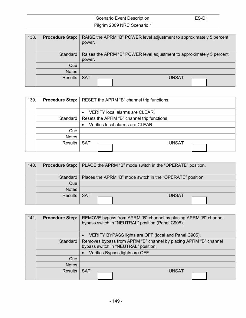
Scenario Event Description ES-D1
Pilgrim 2009 NRC Scenario 1
- 149 -
138. Procedure Step: RAISE the APRM “B” POWER level adjustment to approximately 5 percent power.
Standard Raises the APRM “B” POWER level adjustment to approximately 5 percent power.
Cue Notes
Results SAT UNSAT
139. Procedure Step: RESET the APRM “B” channel trip functions.
• VERIFY local alarms are CLEAR. Standard Resets the APRM “B” channel trip functions.
• Verifies local alarms are CLEAR. Cue
Notes Results SAT UNSAT
140. Procedure Step: PLACE the APRM “B” mode switch in the “OPERATE” position.
Standard Places the APRM “B” mode switch in the “OPERATE” position. Cue
Notes Results SAT UNSAT
141. Procedure Step: REMOVE bypass from APRM “B” channel by placing APRM “B” channel bypass switch in “NEUTRAL” position (Panel C905).
• VERIFY BYPASS lights are OFF (local and Panel C905). Standard Removes bypass from APRM “B” channel by placing APRM “B” channel
bypass switch in “NEUTRAL” position.
• Verifies Bypass lights are OFF. Cue
Notes Results SAT UNSAT

Scenario Event Description ES-D1
Pilgrim 2009 NRC Scenario 1
- 150 -
STOP TIME:

Scenario Event Description ES-D1
Pilgrim 2009 NRC Scenario 1
- 151 -
INITIAL CONDITIONS:
• A plant startup is in progress
• APRM “B” Functional Test has begun IAW 8.M.1-3.1, Attachment 2, and is complete through Step [5]
INITIATING CUE: Perform APRM “B” Functional Test in accordance with 8.M.1-3.1, Attachment 2. Begin at procedure Step [6].
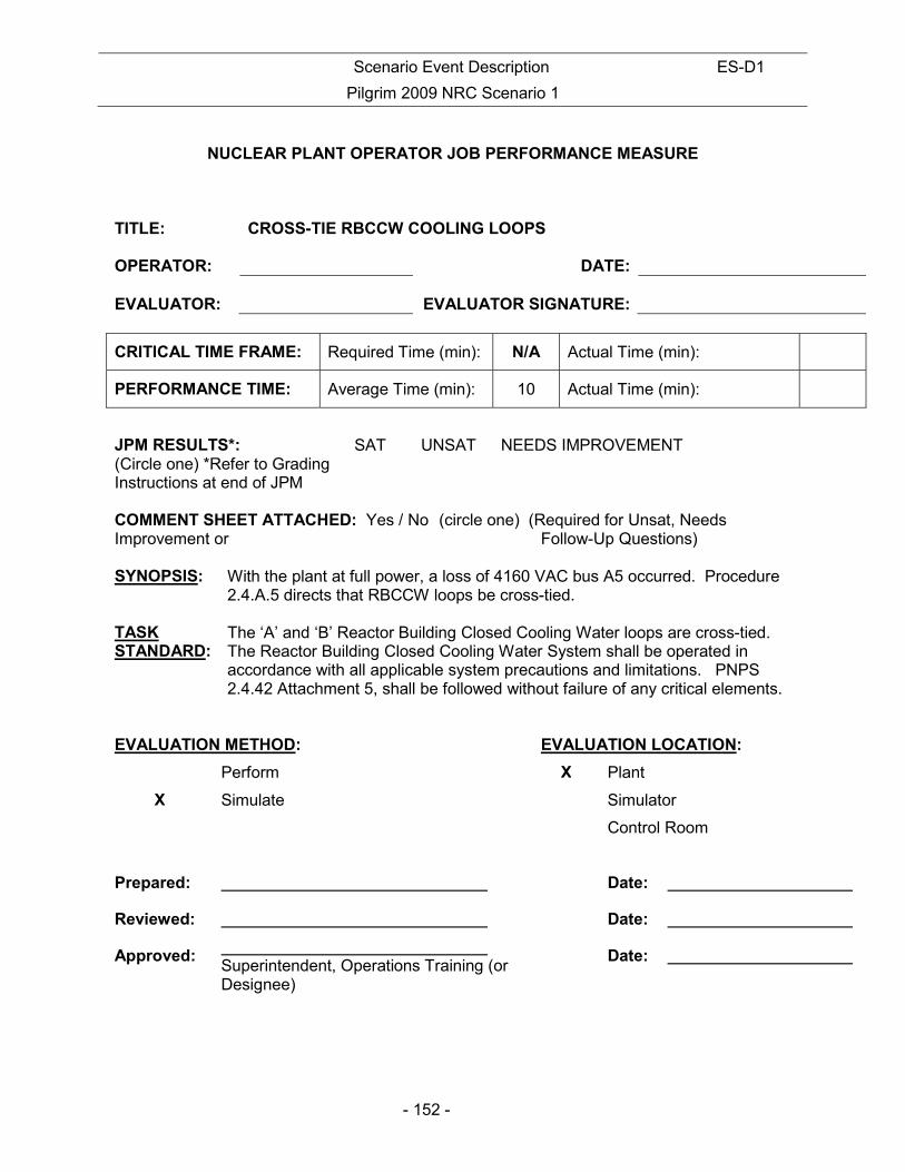
Scenario Event Description ES-D1
Pilgrim 2009 NRC Scenario 1
- 152 -
NUCLEAR PLANT OPERATOR JOB PERFORMANCE MEASURE
TITLE: CROSS-TIE RBCCW COOLING LOOPS OPERATOR:
DATE:
EVALUATOR:
EVALUATOR SIGNATURE:
CRITICAL TIME FRAME: Required Time (min): N/A Actual Time (min):
PERFORMANCE TIME: Average Time (min): 10 Actual Time (min):
JPM RESULTS*: (Circle one) *Refer to Grading Instructions at end of JPM
SAT UNSAT NEEDS IMPROVEMENT
COMMENT SHEET ATTACHED: Yes / No (circle one) (Required for Unsat, Needs Improvement or Follow-Up Questions) SYNOPSIS:
With the plant at full power, a loss of 4160 VAC bus A5 occurred. Procedure 2.4.A.5 directs that RBCCW loops be cross-tied.
TASK STANDARD:
The ‘A’ and ‘B’ Reactor Building Closed Cooling Water loops are cross-tied. The Reactor Building Closed Cooling Water System shall be operated in accordance with all applicable system precautions and limitations. PNPS 2.4.42 Attachment 5, shall be followed without failure of any critical elements.
EVALUATION METHOD: EVALUATION LOCATION:
Perform X Plant
X Simulate Simulator
Control Room
Prepared: Date:
Reviewed: Date:
Approved: Superintendent, Operations Training (or Designee)
Date:
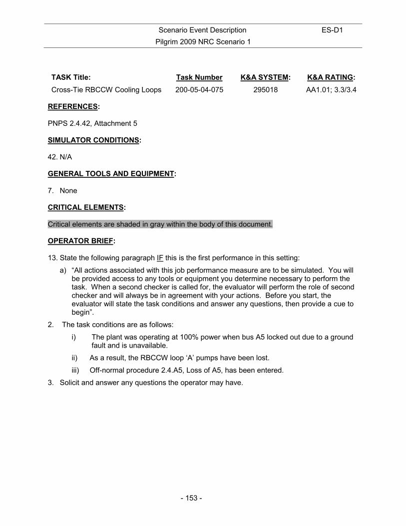
Scenario Event Description ES-D1
Pilgrim 2009 NRC Scenario 1
- 153 -
TASK Title: Task Number K&A SYSTEM: K&A RATING:
Cross-Tie RBCCW Cooling Loops 200-05-04-075 295018 AA1.01; 3.3/3.4 REFERENCES: PNPS 2.4.42, Attachment 5 SIMULATOR CONDITIONS: 42. N/A GENERAL TOOLS AND EQUIPMENT: 7. None CRITICAL ELEMENTS: Critical elements are shaded in gray within the body of this document. OPERATOR BRIEF: 13. State the following paragraph IF this is the first performance in this setting:
a) “All actions associated with this job performance measure are to be simulated. You will be provided access to any tools or equipment you determine necessary to perform the task. When a second checker is called for, the evaluator will perform the role of second checker and will always be in agreement with your actions. Before you start, the evaluator will state the task conditions and answer any questions, then provide a cue to begin”.
2. The task conditions are as follows:
i) The plant was operating at 100% power when bus A5 locked out due to a ground fault and is unavailable.
ii) As a result, the RBCCW loop ‘A’ pumps have been lost.
iii) Off-normal procedure 2.4.A5, Loss of A5, has been entered.
3. Solicit and answer any questions the operator may have.
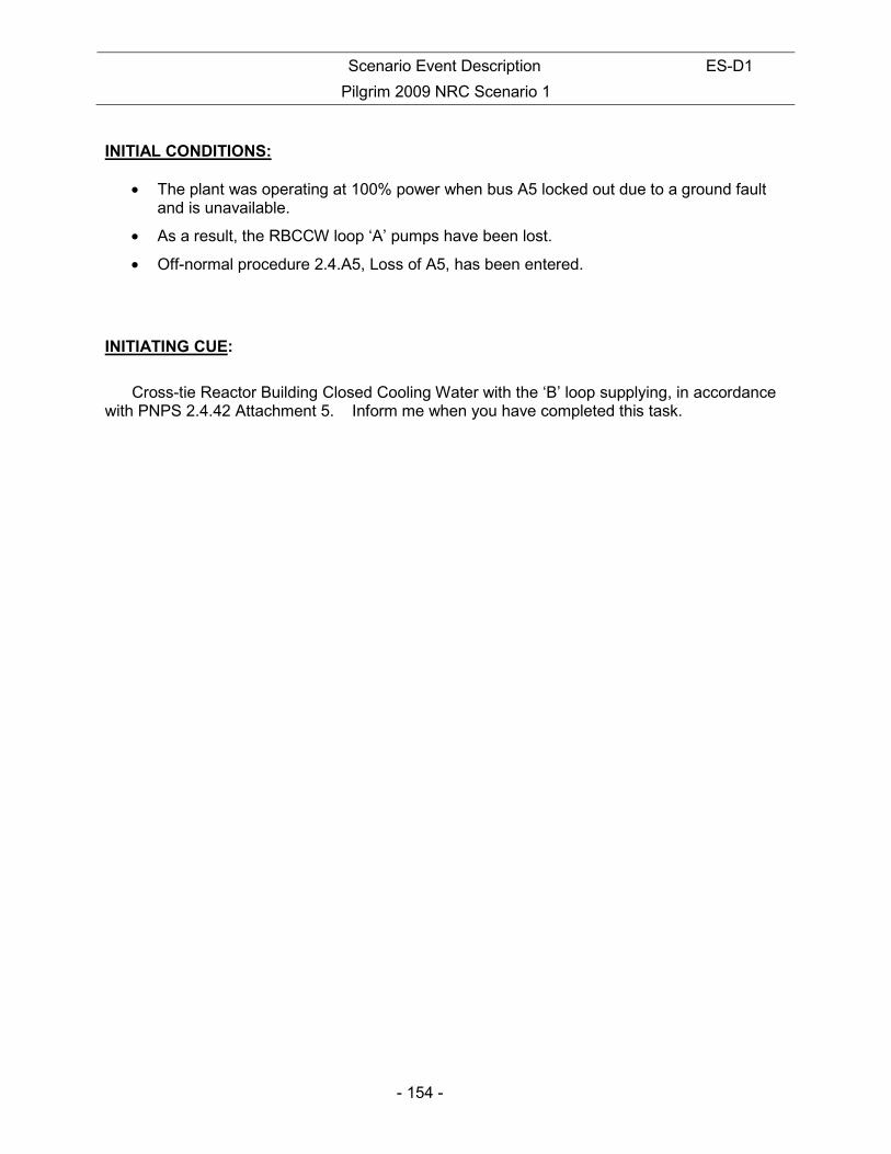
Scenario Event Description ES-D1
Pilgrim 2009 NRC Scenario 1
- 154 -
INITIAL CONDITIONS:
• The plant was operating at 100% power when bus A5 locked out due to a ground fault and is unavailable.
• As a result, the RBCCW loop ‘A’ pumps have been lost.
• Off-normal procedure 2.4.A5, Loss of A5, has been entered.
INITIATING CUE:
Cross-tie Reactor Building Closed Cooling Water with the ‘B’ loop supplying, in accordance with PNPS 2.4.42 Attachment 5. Inform me when you have completed this task.

Scenario Event Description ES-D1
Pilgrim 2009 NRC Scenario 1
- 155 -
PERFORMANCE: Notes This task is covered in 2.4.42, Attachment 5.
Operator reviews the applicable section of the procedure. All critical steps must be simulated in order written unless otherwise noted. 2.4.42 Attachment 5 includes a CAUTION which states in part, “RBCCW shall NOT be cross-tied if Torus Temp is greater than or equal to 130F.” Operator may ask for Torus Temperature. Respond “75 degrees F”
START TIME:
142. Procedure Step: [1] PLACE/VERIFY sufficient RBCCW pumps in service in the active loop.
Standard Operator calls Control Room.
Cue Control Room reports that, “RBCCW pumps ‘D’ and ‘E’ are in service in RBCCW Loop ‘B’.”
Notes
Results SAT UNSAT
143. Procedure Step: [2] SECURE any running RBCCW pump(s) in the idle loop from Panel C1.
Standard Operator calls Control Room.
Cue Control Room reports, “There are no pumps running on Loop “A”.”
Notes
Results SAT UNSAT
144. Procedure Step: [3] PLACE all three control switches for RBCCW pumps in the idle loop to
“PULL-TO-LOCK” at Panel C1.
Standard Operator calls Control Room.
Cue Control Room reports that, “RBCCW Pump ‘A’, ‘B’ & ‘C’ switches are in “PULL-TO-LOCK.”
Notes
Results SAT UNSAT
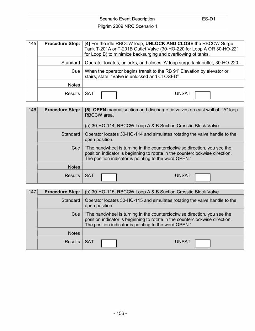
Scenario Event Description ES-D1
Pilgrim 2009 NRC Scenario 1
- 156 -
145. Procedure Step: [4] For the idle RBCCW loop, UNLOCK AND CLOSE the RBCCW Surge
Tank T-201A or T-201B Outlet Valve (30-HO-220 for Loop A OR 30-HO-221 for Loop B) to minimize backsurging and overflowing of tanks.
Standard Operator locates, unlocks, and closes ‘A’ loop surge tank outlet, 30-HO-220.
Cue When the operator begins transit to the RB 91’ Elevation by elevator or stairs, state: “Valve is unlocked and CLOSED”
Notes
Results SAT UNSAT
146. Procedure Step: [5] OPEN manual suction and discharge tie valves on east wall of “A” loop
RBCCW area. (a) 30-HO-114, RBCCW Loop A & B Suction Crosstie Block Valve
Standard Operator locates 30-HO-114 and simulates rotating the valve handle to the open position.
Cue “The handwheel is turning in the counterclockwise direction, you see the position indicator is beginning to rotate in the counterclockwise direction. The position indicator is pointing to the word OPEN.”
Notes
Results SAT UNSAT
147. Procedure Step: (b) 30-HO-115, RBCCW Loop A & B Suction Crosstie Block Valve
Standard Operator locates 30-HO-115 and simulates rotating the valve handle to the open position.
Cue “The handwheel is turning in the counterclockwise direction, you see the position indicator is beginning to rotate in the counterclockwise direction. The position indicator is pointing to the word OPEN.”
Notes
Results SAT UNSAT

Scenario Event Description ES-D1
Pilgrim 2009 NRC Scenario 1
- 157 -
148. Procedure Step: (c) 30-HO-192, RBCCW Loop A & B Discharge Crosstie Block Valve
Standard Operator locates 30-HO-192 and simulates rotating the valve handle to the open position.
Cue “The handwheel is turning in the counterclockwise direction, you see the position indicator is beginning to rotate in the counterclockwise direction. The position indicator is pointing to the word OPEN.”
Notes
Results SAT UNSAT
149. Procedure Step: (d) 30-HO-193, RBCCW Loop A & B Discharge Crosstie Block Valve
Standard Operator locates 30-HO-193 and simulates rotating the valve handle to the open position.
Cue “The handwheel is turning in the counterclockwise direction, you see the position indicator is beginning to rotate in the counterclockwise direction. The position indicator is pointing to the word OPEN.”
Notes
Results SAT UNSAT
150. Procedure Step:
Standard Operator contacts the Control Room and informs them that the RBCCW loops have been cross-tied.
Cue “This completes the JPM.”
Notes
Results SAT UNSAT
STOP TIME:

Scenario Event Description ES-D1
Pilgrim 2009 NRC Scenario 1
- 158 -
INITIAL CONDITIONS:
• The plant was operating at 100% power when bus A5 locked out due to a ground fault and is unavailable.
• As a result, the RBCCW loop ‘A’ pumps have been lost.
• Off-normal procedure 2.4.A5, Loss of A5, has been entered.
INITIATING CUE:
Cross-tie Reactor Building Closed Cooling Water with the ‘B’ loop supplying, in accordance with PNPS 2.4.42 Attachment 5. Inform me when you have completed this task.

Scenario Event Description ES-D1
Pilgrim 2009 NRC Scenario 1
- 159 -
NUCLEAR PLANT OPERATOR JOB PERFORMANCE MEASURE TITLE: RCIC START FROM THE ALTERNATE SHUTDOWN PANELS OPERATOR:
DATE:
EVALUATOR:
EVALUATOR SIGNATURE:
CRITICAL TIME FRAME: Required Time (min): 20 Actual Time (min):
PERFORMANCE TIME: Average Time (min): 16 Actual Time (min):
JPM RESULTS*: (Circle one) *Refer to Grading Instructions at end of JPM
SAT UNSAT NEEDS IMPROVEMENT
COMMENT SHEET ATTACHED: Yes / No (circle one) (Required for Unsat, Needs Improvement or Follow-Up Questions) SYNOPSIS:
The operator will place RCIC in service from the alternate shutdown panels for level control following control room abandonment due to a fire.
TASK STANDARD:
The RCIC turbine will be in operation from the Alternate Shutdown Panels in the level control mode. The system shall be operated in accordance with all applicable precautions and limitations. The procedure shall be followed without failure of any critical elements.
EVALUATION METHOD: EVALUATION LOCATION:
Perform X Plant
X Simulate Simulator
Control Room
Prepared: Date:
Reviewed: Date:
Approved: Superintendent, Operations Training (or Designee)
Date:

Scenario Event Description ES-D1
Pilgrim 2009 NRC Scenario 1
- 160 -
TASK Title: Task Number K&A SYSTEM: K&A RATING:
Manually Operate and Adjust RCIC System Flow With RCIC Flow Controls At Alternate Shutdown Panel
217-02-01-006 295016 AA1.06 4.0/4.1
REFERENCES: PNPS 2.4.143 SIMULATOR CONDITIONS: 43. N/A GENERAL TOOLS AND EQUIPMENT: 1. Keys to Alternate Shutdown Panels C-154 and C-159 (ASP Key Ring CR-66 or CRA051). CRITICAL ELEMENTS: Critical elements are shaded in gray within the body of this document. OPERATOR BRIEF: 14. State the following paragraph IF this is the first performance in this setting:
a) “All actions associated with this job performance measure are to be simulated. You will be provided access to any tools or equipment you determine necessary to perform the task. When a second checker is called for, the evaluator will perform the role of second checker and will always be in agreement with your actions. Before you start, the evaluator will state the task conditions and answer any questions, then provide a cue to begin”.
15. The task conditions are as follows:
a) The control room has been evacuated due to a fire
b) The reactor has been scrammed successfully
c) RPV level control has not been established
d) RCIC must be started to accomplish RPV level control
e) Communications have been established with the Shift Manager, who is standing by the level instrument rack 2205 and with an operator stationed at Rack 2258 with walkie-talkies or a cellular phone.
16. Solicit and answer any questions the operator may have.
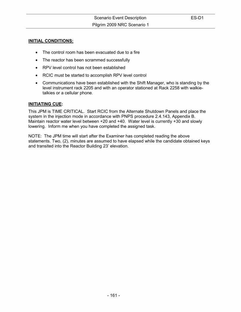
Scenario Event Description ES-D1
Pilgrim 2009 NRC Scenario 1
- 161 -
INITIAL CONDITIONS:
• The control room has been evacuated due to a fire
• The reactor has been scrammed successfully
• RPV level control has not been established
• RCIC must be started to accomplish RPV level control
• Communications have been established with the Shift Manager, who is standing by the level instrument rack 2205 and with an operator stationed at Rack 2258 with walkie-talkies or a cellular phone.
INITIATING CUE:
This JPM is TIME CRITICAL. Start RCIC from the Alternate Shutdown Panels and place the system in the injection mode in accordance with PNPS procedure 2.4.143, Appendix B. Maintain reactor water level between +20 and +40. Water level is currently +30 and slowly lowering. Inform me when you have completed the assigned task.
NOTE: The JPM time will start after the Examiner has completed reading the above statements. Two, (2), minutes are assumed to have elapsed while the candidate obtained keys and transited into the Reactor Building 23’ elevation.
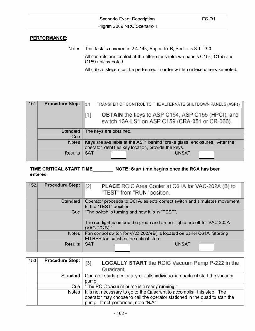
Scenario Event Description ES-D1
Pilgrim 2009 NRC Scenario 1
- 162 -
PERFORMANCE:
Notes This task is covered in 2.4.143, Appendix B, Sections 3.1 - 3.3.
All controls are located at the alternate shutdown panels C154, C155 and C159 unless noted.
All critical steps must be performed in order written unless otherwise noted.
151. Procedure Step:
Standard The keys are obtained. Cue
Notes Keys are available at the ASP, behind “brake glass” enclosures. After the operator identifies key location, provide the keys.
Results SAT UNSAT
TIME CRITICAL START TIME________ NOTE: Start time begins once the RCA has been entered
152. Procedure Step:
Standard Operator proceeds to C61A, selects correct switch and simulates movement to the “TEST” position.
Cue “The switch is turning and now it is in “TEST”. The red light is on and the green and amber lights are off for VAC 202A (VAC 202B).”
Notes Fan control switch for VAC 202A(B) is located on panel C61A. Starting EITHER fan satisfies the critical step.
Results SAT UNSAT
153. Procedure Step:
Standard Operator starts personally or calls individual in quadrant start the vacuum pump.
Cue “The RCIC vacuum pump is already running.” Notes It is not necessary to go to the Quadrant to accomplish this step. The
operator may choose to call the operator stationed in the quad to start the pump. If not performed, note “N/A”.

Scenario Event Description ES-D1
Pilgrim 2009 NRC Scenario 1
- 163 -
Results SAT UNSAT
NOTE
Valve MO-2301-15 may already be in use if HPCI is in operation.
154. Procedure Step: [4] PLACE the control switch to MO-2301-15 (HPCI/RCIC Test Return Valve) at ASP C155 (HPCI Quad entrance) to the pushed-in NORMAL position.
Standard Operator simulates pushing in the Control switch for MO-2301-15 Cue “The control switch is pushed in.”
Notes Results SAT UNSAT
155. Procedure Step: [5] OPEN OR CHECK OPEN valve MO-2301-15 from ASP C155.
Standard Operator identifies correct switch and motions in the proper direction. Cue “The red light is on and the green light is off.”
Notes Results SAT UNSAT
156. Procedure Step: [6] PLACE switch 13A-LS1 at ASP C159 (RCIC ASP) to “LOCAL”. Standard Operator locates correct switch and simulates motion in proper direction.
Cue “Switch 13A-LS1 is in local.” Notes
Results SAT UNSAT

Scenario Event Description ES-D1
Pilgrim 2009 NRC Scenario 1
- 164 -
157. Procedure Step: [7] PLACE all control switches (five valve control switches) in
ASP C154 out of “PULL-TO-LOCK” and into the pushed-in NORMAL position:
• MO-1301-49, RCIC Injection Valve #2 • MO-1301-53, RCIC Full Flow Test Valve • MO-1301-60, RCIC Pump Minimum Flow Valve • MO-1301-61, RCIC Turbine Steam Inlet Valve
• MO-1301-62, RCIC Cooling Water Supply Valve
Standard Operator simulates pushing in all control switches. Cue After each switch is pointed to, “The control switch is pushed in.”
Notes Switches may be pushed in any order as long as all 5 get pushed in. Results SAT UNSAT
158. Procedure Step: [8] VERIFY/PLACE the power supply “ON” at Power Supply Panel N551, adjacent to C154 and C159.
Standard Operator locates correct switch and simulates motion in proper direction. Cue “The switch is simulated in the ON position.
The red light is on, voltage indicates 120 volts, current indicates slightly above 0 amps.”
Notes Results SAT UNSAT
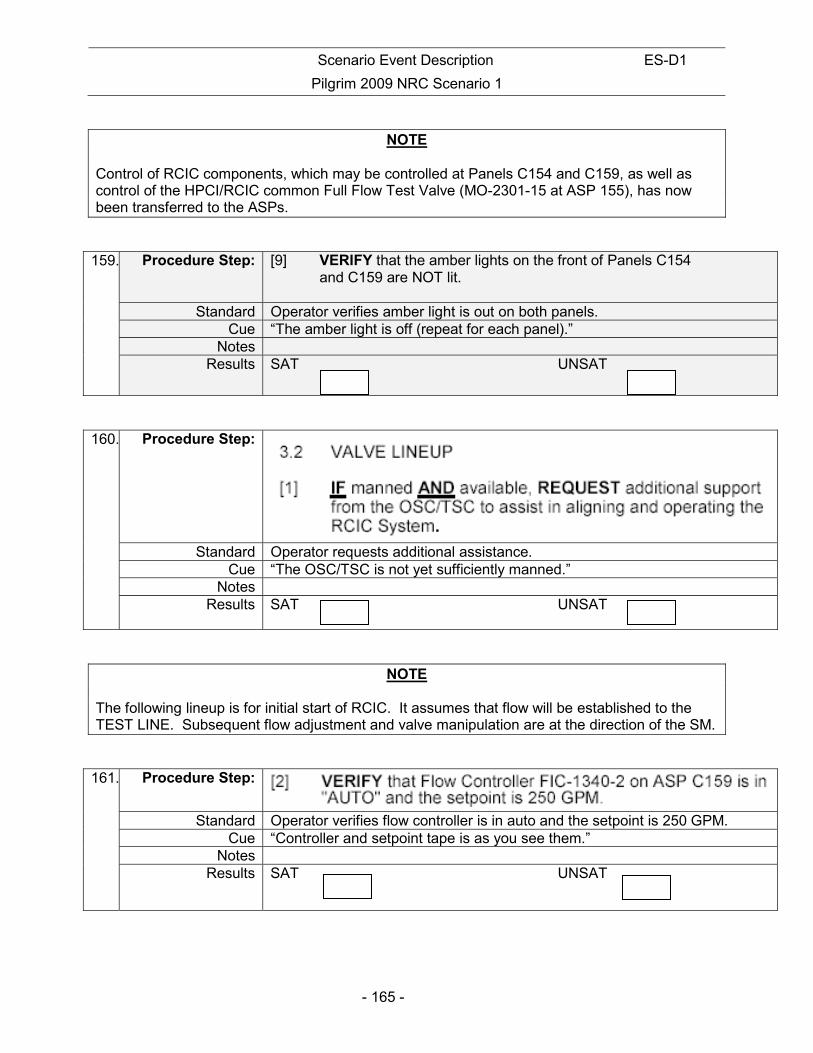
Scenario Event Description ES-D1
Pilgrim 2009 NRC Scenario 1
- 165 -
NOTE
Control of RCIC components, which may be controlled at Panels C154 and C159, as well as control of the HPCI/RCIC common Full Flow Test Valve (MO-2301-15 at ASP 155), has now been transferred to the ASPs.
159. Procedure Step: [9] VERIFY that the amber lights on the front of Panels C154 and C159 are NOT lit.
Standard Operator verifies amber light is out on both panels. Cue “The amber light is off (repeat for each panel).”
Notes Results SAT UNSAT
160. Procedure Step:
Standard Operator requests additional assistance. Cue “The OSC/TSC is not yet sufficiently manned.”
Notes Results SAT UNSAT
NOTE The following lineup is for initial start of RCIC. It assumes that flow will be established to the TEST LINE. Subsequent flow adjustment and valve manipulation are at the direction of the SM.
161. Procedure Step:
Standard Operator verifies flow controller is in auto and the setpoint is 250 GPM. Cue “Controller and setpoint tape is as you see them.”
Notes Results SAT UNSAT

Scenario Event Description ES-D1
Pilgrim 2009 NRC Scenario 1
- 166 -
162. Procedure Step: [3] OPEN MO-1301-62, Cooling Water Supply Vlv, on ASP C154
Standard Operator identifies the proper control switch and simulates rotation in the proper direction.
Cue “The red light is on and the green light is off.” Notes
Results SAT UNSAT
163. Procedure Step:
Standard Operator simulates verifying indications and/or notes the valve has been checked open already.
Cue “The red light is on and the green light is off.” Notes The operator may indicate that the position of the valve has already been
checked. In this case no cue is required. Results SAT UNSAT
164. Procedure Step: [5] JOG OPEN MO-1301-53, RCIC Full Flow Test Valve, for 6 seconds.
Standard Operator locates and simulates opening of MO-1301-53 for six seconds. Cue “The red and green lights are both on.”
Notes C154 Results SAT UNSAT

Scenario Event Description ES-D1
Pilgrim 2009 NRC Scenario 1
- 167 -
CAUTION
During normal operation, the turbine should not be run below 2000 RPM. Below 2000 RPM, intermittent exhaust flow will cause water hammer in the exhaust line. If turbine operation below 2000 RPM is required to achieve and/or maintain adequate core cooling, then the turbine should not be run below 1000 RPM. This will ensure adequate oil pressure to maintain the stop valve open and bearing lubrication. The time the turbine is run below 2000, RPM should be kept to a minimum.
165. Procedure Step: 3.3 TURBINE STARTUP AND SYSTEM OPERATION [1] OPEN MO-1301-61, RCIC Turbine Supply Valve, from ASP C154 AND OBSERVE that the Turbine starts. IF problems are encountered, REFER TO Precaution 2.0[5] of Appendix B.
Standard Operator identifies correct control switch and motions operations in proper direction.
Cue “The red light is on and the green light is off.” Notes
Results SAT UNSAT
166. Procedure Step: Standard Operator verifies increase in turbine speed.
Cue “SI-1340-2 is rising and stabilizes at 2800 RPM.” Notes C159
Results SAT UNSAT
167. Procedure Step: Standard Operator verifies flow.
Cue “FI-1340-2 is rising and stabilizes at 250 GPM.” Notes C159
Results SAT UNSAT

Scenario Event Description ES-D1
Pilgrim 2009 NRC Scenario 1
- 168 -
168. Procedure Step:
Standard Operator monitors system. Cue As the SM, “Place RCIC in the injection mode.”
Notes Results SAT UNSAT
NOTE The next few steps will affect RCIC discharge pressure and steam demand. FIC-1340-2 and MO-1301-53 should be manipulated in tandem such that Reactor Vessel pressure and level are controlled as desired. RCIC discharge pressure can be monitored at PI-1360-5 (Rack C2258) if desired.
CAUTION DO NOT bring RCIC flow below 200 GPM when injecting to the Reactor Vessel (MO-1301-49 OPEN) in the AUTO mode of control.
169. Procedure Step: [3] PERFORM the following steps to swap over to injection:
(a) USE MO-1301-53, RCIC Full Flow Test Valve, on ASP C154 to adjust pump discharge pressure to less than Reactor pressure.
Standard Operator reviews Note and Caution then, simulates opening MO-1301-53 and/or adjusts FIC-1340-2 until cued that discharge pressure is less than reactor pressure.
Cue As the operator at C2258, “Discharge pressure is below reactor pressure.” Notes The operator may call the operator at rack 2258 to determine reactor
pressure and RCIC pump discharge pressure. Results SAT UNSAT

Scenario Event Description ES-D1
Pilgrim 2009 NRC Scenario 1
- 169 -
170. Procedure Step: (b) OPEN MO-1301-49 Injection Valve #2 on ASP C154.
Standard Operator simulates taking the control switch for MO-1301-49 to the open
position. Cue “Red light is on, green light is off.”
Notes Results SAT UNSAT
171. Procedure Step:
Standard Operator simulates taking the control switch for MO-1301-53 to the closed position momentarily.
Cue As the SM, “RPV level is +25 inches and slowly rising.” Notes
Results SAT UNSAT
TIME CRITICAL STOP TIME________
Cue: This completes this JPM.
STOP TIME:

Scenario Event Description ES-D1
Pilgrim 2009 NRC Scenario 1
- 170 -
INITIAL CONDITIONS:
• The control room has been evacuated due to a fire
• The reactor has been scrammed successfully
• RPV level control has not been established
• RCIC must be started to accomplish RPV level control
• Communications have been established with the Shift Manager, who is standing by the level instrument rack 2205 and with an operator stationed at Rack 2258 with walkie-talkies or a cellular phone.
INITIATING CUE:
This JPM is TIME CRITICAL. Start RCIC from the Alternate Shutdown Panels and place the system in the injection mode in accordance with PNPS procedure 2.4.143, Appendix B. Maintain reactor water level between +20 and +40. Water level is currently +30 and slowly lowering. Inform me when you have completed the assigned task.
NOTE: The JPM time will start after the Examiner has completed reading the above statements. Two, (2), minutes are assumed to have elapsed while the candidate obtained keys and transited into the Reactor Building 23’ elevation.

Scenario Event Description ES-D1
Pilgrim 2009 NRC Scenario 1
- 171 -
NUCLEAR PLANT OPERATOR JOB PERFORMANCE MEASURE TITLE: LOCAL START AND FIELD FLASH OF AN EDG OPERATOR:
DATE:
EVALUATOR:
EVALUATOR SIGNATURE:
CRITICAL TIME FRAME: Required Time (min): N/A Actual Time (min): N/A
PERFORMANCE TIME: Average Time (min): 8 Actual Time (min):
JPM RESULTS*: (Circle one) *Refer to Grading Instructions at end of JPM
SAT UNSAT NEEDS IMPROVEMENT
COMMENT SHEET ATTACHED: Yes / No (circle one) (Required for Unsat, Needs Improvement or Follow-Up Questions) SYNOPSIS:
Following a loss of all AC power and loss of DC power to the A EDG, the operator is required to start the “A” DG at the air start solenoids and then flash the field with two 12-volt batteries.
TASK STANDARD:
The ‘A’ DG is running and ready to load. The system shall be operated in accordance with all applicable precautions and limitations. The procedure shall be followed without failure of critical elements.
EVALUATION METHOD: EVALUATION LOCATION:
Perform X Plant
X Simulate Simulator
Control Room
Prepared: Date:
Reviewed: Date:
Approved: Superintendent, Operations Training (or Designee)
Date:
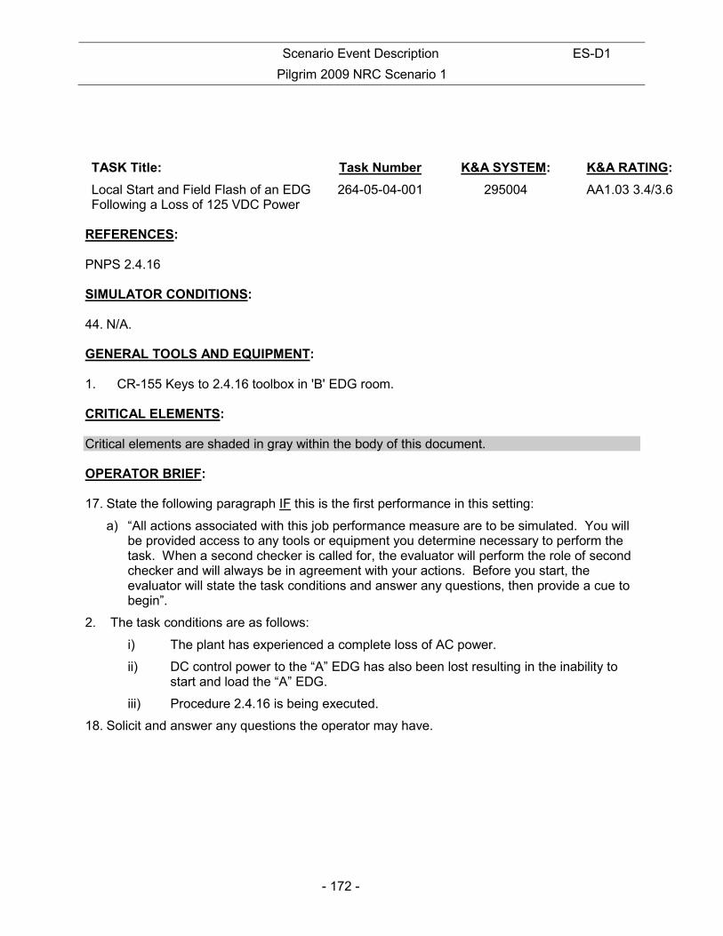
Scenario Event Description ES-D1
Pilgrim 2009 NRC Scenario 1
- 172 -
TASK Title: Task Number K&A SYSTEM: K&A RATING:
Local Start and Field Flash of an EDG Following a Loss of 125 VDC Power
264-05-04-001 295004 AA1.03 3.4/3.6
REFERENCES: PNPS 2.4.16 SIMULATOR CONDITIONS: 44. N/A. GENERAL TOOLS AND EQUIPMENT: 1. CR-155 Keys to 2.4.16 toolbox in 'B' EDG room. CRITICAL ELEMENTS: Critical elements are shaded in gray within the body of this document. OPERATOR BRIEF: 17. State the following paragraph IF this is the first performance in this setting:
a) “All actions associated with this job performance measure are to be simulated. You will be provided access to any tools or equipment you determine necessary to perform the task. When a second checker is called for, the evaluator will perform the role of second checker and will always be in agreement with your actions. Before you start, the evaluator will state the task conditions and answer any questions, then provide a cue to begin”.
2. The task conditions are as follows:
i) The plant has experienced a complete loss of AC power.
ii) DC control power to the “A” EDG has also been lost resulting in the inability to start and load the “A” EDG.
iii) Procedure 2.4.16 is being executed.
18. Solicit and answer any questions the operator may have.

Scenario Event Description ES-D1
Pilgrim 2009 NRC Scenario 1
- 173 -
INITIAL CONDITIONS:
• The plant has experienced a complete loss of AC power.
• DC control power to the “A” EDG has also been lost resulting in the inability to start and load the “A” EDG.
• Procedure 2.4.16 is being executed.
INITIATING CUE:
Start the “A” EDG and flash the field in accordance with PNPS 2.4.16, Attachment 3. Inform me when you have completed the assigned task."
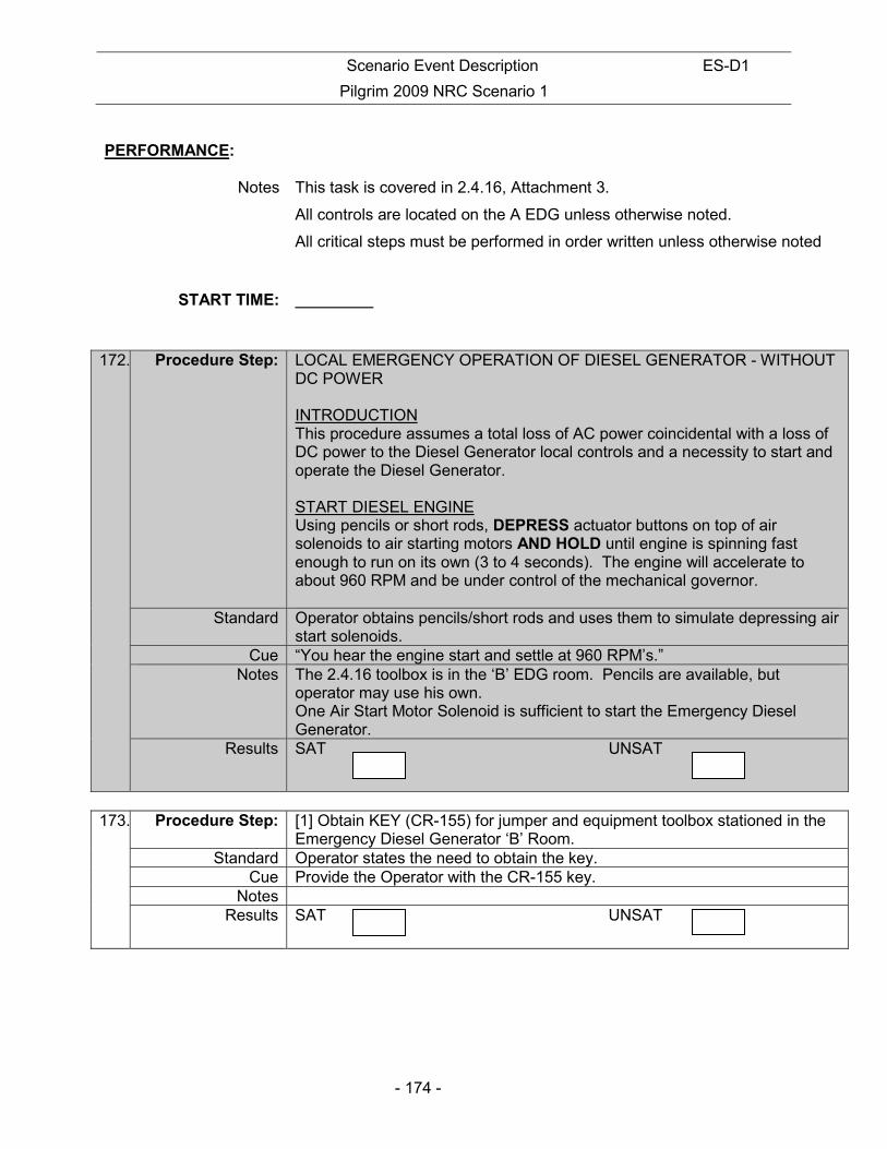
Scenario Event Description ES-D1
Pilgrim 2009 NRC Scenario 1
- 174 -
PERFORMANCE:
Notes This task is covered in 2.4.16, Attachment 3.
All controls are located on the A EDG unless otherwise noted.
All critical steps must be performed in order written unless otherwise noted
START TIME:
172. Procedure Step: LOCAL EMERGENCY OPERATION OF DIESEL GENERATOR - WITHOUT DC POWER INTRODUCTION This procedure assumes a total loss of AC power coincidental with a loss of DC power to the Diesel Generator local controls and a necessity to start and operate the Diesel Generator. START DIESEL ENGINE Using pencils or short rods, DEPRESS actuator buttons on top of air solenoids to air starting motors AND HOLD until engine is spinning fast enough to run on its own (3 to 4 seconds). The engine will accelerate to about 960 RPM and be under control of the mechanical governor.
Standard Operator obtains pencils/short rods and uses them to simulate depressing air start solenoids.
Cue “You hear the engine start and settle at 960 RPM’s.” Notes The 2.4.16 toolbox is in the ‘B’ EDG room. Pencils are available, but
operator may use his own. One Air Start Motor Solenoid is sufficient to start the Emergency Diesel Generator.
Results SAT UNSAT
173. Procedure Step: [1] Obtain KEY (CR-155) for jumper and equipment toolbox stationed in the
Emergency Diesel Generator ‘B’ Room. Standard Operator states the need to obtain the key.
Cue Provide the Operator with the CR-155 key. Notes
Results SAT UNSAT
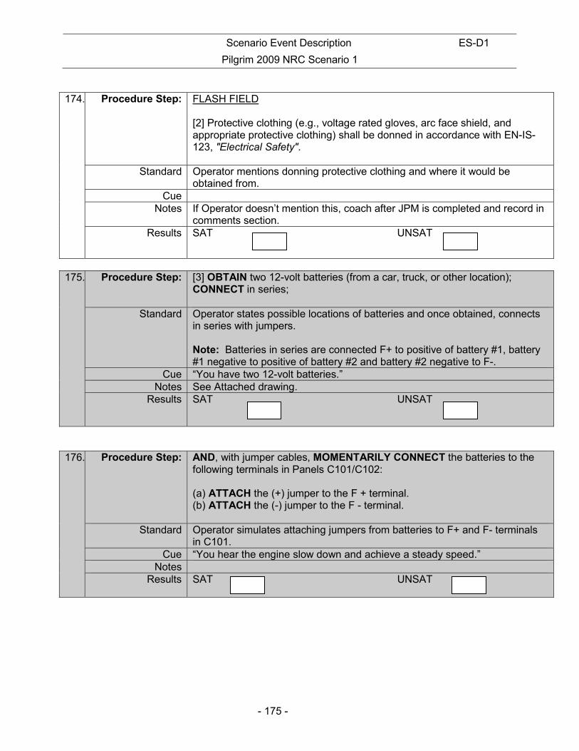
Scenario Event Description ES-D1
Pilgrim 2009 NRC Scenario 1
- 175 -
174. Procedure Step: FLASH FIELD
[2] Protective clothing (e.g., voltage rated gloves, arc face shield, and appropriate protective clothing) shall be donned in accordance with EN-IS-123, "Electrical Safety".
Standard Operator mentions donning protective clothing and where it would be obtained from.
Cue Notes If Operator doesn’t mention this, coach after JPM is completed and record in
comments section. Results SAT UNSAT
175. Procedure Step: [3] OBTAIN two 12-volt batteries (from a car, truck, or other location);
CONNECT in series;
Standard Operator states possible locations of batteries and once obtained, connects in series with jumpers. Note: Batteries in series are connected F+ to positive of battery #1, battery #1 negative to positive of battery #2 and battery #2 negative to F-.
Cue “You have two 12-volt batteries.” Notes See Attached drawing.
Results SAT UNSAT
176. Procedure Step: AND, with jumper cables, MOMENTARILY CONNECT the batteries to the following terminals in Panels C101/C102: (a) ATTACH the (+) jumper to the F + terminal. (b) ATTACH the (-) jumper to the F - terminal.
Standard Operator simulates attaching jumpers from batteries to F+ and F- terminals in C101.
Cue “You hear the engine slow down and achieve a steady speed.” Notes
Results SAT UNSAT
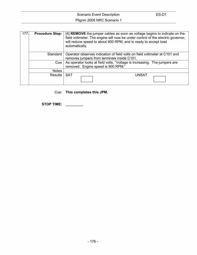
Scenario Event Description ES-D1
Pilgrim 2009 NRC Scenario 1
- 176 -
177. Procedure Step: [4] REMOVE the jumper cables as soon as voltage begins to indicate on the
field voltmeter. The engine will now be under control of the electric governor, will reduce speed to about 900 RPM, and is ready to accept load automatically.
Standard Operator observes indication of field volts on field voltmeter at C101 and removes jumpers from terminals inside C101.
Cue As operator looks at field volts, “Voltage is increasing. The jumpers are removed. Engine speed is 900 RPM.”
Notes Results SAT UNSAT
Cue: This completes this JPM.
STOP TIME:

Scenario Event Description ES-D1
Pilgrim 2009 NRC Scenario 1
- 177 -
INITIAL CONDITIONS:
• The plant has experienced a complete loss of AC power.
• DC control power to the “A” EDG has also been lost resulting in the inability to start and load the “A” EDG.
• Procedure 2.4.16 is being executed.
INITIATING CUE:
Start the “A” EDG and flash the field in accordance with PNPS 2.4.16, Attachment 3. Inform me when you have completed the assigned task."

Scenario Event Description ES-D1
Pilgrim 2009 NRC Scenario 1
- 178 -
Facility: PILGRIM Scenario No.: 1 Op Test No.: 2009 NRC
Examiners: Operators: SRO -
RO -
BOP -
Initial Conditions: • Reactor Power is 100%
• APRM C is bypassed while I & C replaces a power supply.
• B RHR Pump will be OOS for maintenance. Currently in day 1 of a 7 day LCO
• B Feedwater Pump has a bad pump seal and must be secured and isolated.
Turnover: • Reduce Reactor Power IAW 2.1.14 Sections 7.11 & 7.9, continue power reduction with the RPR, then remove the B Feedwater Pump from service
Critical Tasks: 1. Restore power to at least one ECCS bus by manually starting the “B” EDG and/or placing the SBO DG in service.
2. When RPV level cannot be restored and maintained above (-150 inches), Emergency Depressurization is directed and performed.
3. Restores RPV level above +12 inches using low-pressure ECCS pumps.
Event No.
Malf. No. Event Type*
Event Description
1 R-RO R-SRO
Power reduction required with RPR due to FW pump issue
2 N – BOP N - SRO
Secure Feedwater Pump “B” (PNPS 2.2.96)
3 RD07 for in sequence rod
I – RO I- SRO TS- SRO
Rod drifts out of the core (Rod 10-27)
AOP-2.4.11, Control Rod Positioning Malfunctions, Att 2
ANN C905L-A3 – Rod Drift
TS – 3.3.B.1.C – LCO to fully insert within 3 hours, disarm within 4 hours
4 NM21 – APRM ‘E’ fails downscale
I – RO I – SRO TS - SRO
APRM ‘E’ failure Downscale
ANN-C905L-D8 – APRM Downscale
TS 3.1.1 – action A. place in trip condition within 12 hours

Scenario Event Description ES-D1
Pilgrim 2009 NRC Scenario 1
- 179 -
5 HP01 – HPCI inadvertently starts
C-BOP C-SRO TS-SRO
HPCI Spurious Initiation C905R & C1L-F5
Enters AOP 2.4.35 step 4.0 [1] to secure HPCI
TSs 3.5.A.3, 3.5.B.1.a, 3.5.C.3, 3.5.C.2 is most limiting shutdown/cooldown within 24 hours
6 ED27- loss of line 355
DG03B &
DG02A (5 minutes after loop)
C - ALL Loss of all offsite power. EDG “B” will not auto start, but can be started manually. EDG “A” will tie on initially but will trip shortly and lockout. SBO DG must be started.
EOP-1 entry
Annunciators:
C3R-A8 – Line 355 Undervoltage
B6 – ACB 105 trip
C6 – ACB 102 Trip
AOP-2.4.16 - DISTRIBUTION ALIGNMENT ELECTRICAL SYSTEM MALFUNCTIONS
PNPS 2.2.146
7 PC01 – 1500 gpm
Insert after SBO DG starts OR if SBO DG is not started within 10 minutes of trip of EDG ”A”
M – ALL Recirc leak in Drywell leads to Emergency Depressurization on low RPV level.
EOP-1 – Hi Drywell Pressure
EOP-3 – Hi Drywell pressure
8 RHR04 C – BOP C - SRO
MO-1001-29B LPCI Injection Valve #2 fails to auto open
* (N)ormal, (R)eactivity, (I)nstrument, (C)omponent, (M)ajor

Scenario Event Description ES-D1
Pilgrim 2009 NRC Scenario 1
- 180 -
Pilgrim 2009 NRC Scenario #1 The plant is operating at 100% power, End of Cycle. “B” RHR Pump and APRM “C” are OOS for maintenance. The crew must reduce power and remove the “B” Feedwater Pump from service due to a leaking pump seal. After the Feedwater Pump is secured a control rod will begin to drift out. The RO will take action IAW AOP-2.4.11 to insert the rod. Technical Specifications must be addressed and will require disarming the rod after insertion. APRM ‘E’ will then fail downscale requiring the SRO to address Technical Specification 3.1.1. The RO will be required to insert a half scram on the affected channel. Once the APRM actions are addressed, a spurious HPCI injection will occur requiring action by the BOP to secure HPCI. The SRO will address Technical Specifications for the system being inoperable. A Loss of All Offsite Power will then occur. The “B” Diesel will fail to auto start but can be started manually. The “A” Diesel will start and tie to the bus initially but will trip shortly and lockout. The SBO DG must be started to supply the bus (Critical Task). Once conditions stabilize following the reactor scram and restoration of power, a leak will occur in the Recirculation piping leading to increasing drywell pressure. The crew will continue taking actions in EOP-01 and enter EOP-03 due to high drywell pressure and other degrading containment parameters. The crew will place Suppression Pool Cooling and Spray in service as well as Drywell Spray as required by EOPs. Due to the unavailability of HPCI and the severity of the leak RPV level will continue to lower and the crew will take actions to Emergency Depressurize (Critical Task) and reflood the RPV with low pressure ECCS systems (Critical Task). Complicating the reflood effort will be the failure of LPCI Injection Valve MO-1001-29B to auto-open. The scenario may be terminated when level has been restored to the required EOP band and containment parameters are improving. EAL: Alert – 3.4.1.2 – Drywell Pressure >2.2 psig

Appendix D Operator Action Form ES-D-2
Op Test No.: 2009 Scenario # 1 Event # 1 Event Description: Reduce Reactor Power IAW 2.1.14 and the RPR to <75%
Time Position Applicant’s Actions or Behavior
- 181 -
CRS Brief/Direct Power Reduction IAW the RPR & PNPS 2.1.14 Sections 7.11 & 7.9
NOTE: Annunciator C905L-B4 is an expected alarm during the power reduction
RO
REDUCE core flow as necessary to approximately 43 Mlb/hr then INSERT control rods IAW the RPR
CRS/RO Monitor Power to Flow Map
RO
Continue to monitor Reactor Pressure & Level as reactor power is decreased
When directed by Lead Examiner, proceed to next event
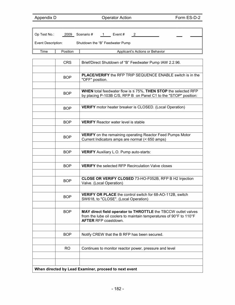
Appendix D Operator Action Form ES-D-2
Op Test No.: 2009 Scenario # 1 Event # 2 Event Description: Shutdown the “B” Feedwater Pump
Time Position Applicant’s Actions or Behavior
- 182 -
CRS Brief/Direct Shutdown of “B” Feedwater Pump IAW 2.2.96.
BOP PLACE/VERIFY the RFP TRIP SEQUENCE ENABLE switch is in the "OFF" position.
BOP WHEN total feedwater flow is ≤ 75%, THEN STOP the selected RFP by placing P-103B C/S, RFP B on Panel C1 to the "STOP" position:
BOP VERIFY motor heater breaker is CLOSED. (Local Operation)
BOP VERIFY Reactor water level is stable
BOP VERIFY on the remaining operating Reactor Feed Pumps Motor Current Indicators amps are normal (< 650 amps)
BOP VERIFY Auxiliary L.O. Pump auto-starts:
BOP VERIFY the selected RFP Recirculation Valve closes
BOP CLOSE OR VERIFY CLOSED 73-HO-F052B, RFP B H2 Injection Valve. (Local Operation)
BOP VERIFY OR PLACE the control switch for 68-AO-112B, switch SW618, to "CLOSE". (Local Operation)
BOP MAY direct field operator to THROTTLE the TBCCW outlet valves from the lube oil coolers to maintain temperatures of 90°F to 110°F AFTER RFP coastdown.
BOP Notify CREW that the B RFP has been secured.
RO Continues to monitor reactor power, pressure and level
When directed by Lead Examiner, proceed to next event
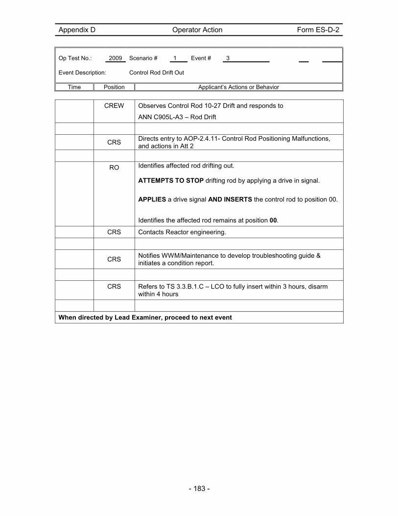
Appendix D Operator Action Form ES-D-2
Op Test No.: 2009 Scenario # 1 Event # 3 Event Description: Control Rod Drift Out
Time Position Applicant’s Actions or Behavior
- 183 -
CREW Observes Control Rod 10-27 Drift and responds to
ANN C905L-A3 – Rod Drift
CRS Directs entry to AOP-2.4.11- Control Rod Positioning Malfunctions, and actions in Att 2
RO Identifies affected rod drifting out. ATTEMPTS TO STOP drifting rod by applying a drive in signal.
APPLIES a drive signal AND INSERTS the control rod to position 00.
Identifies the affected rod remains at position 00.
CRS Contacts Reactor engineering.
CRS
Notifies WWM/Maintenance to develop troubleshooting guide & initiates a condition report.
CRS Refers to TS 3.3.B.1.C – LCO to fully insert within 3 hours, disarm within 4 hours
When directed by Lead Examiner, proceed to next event

Appendix D Operator Action Form ES-D-2
Op Test No.: 2009 Scenario # 1 Event # 4 Event Description: APRM “E” fails downscale
Time Position Applicant’s Actions or Behavior
- 184 -
RO Recognize/announce APRM downscale alarm.
RO Refer to ARP C905L, D8 – APRM Downscale
RO
At Panel C905, check APRM power level and status lights, recognize/report failure of APRM E downscale.
CRS
Send the BOP operator to check the failed APRM on Panel C937.
Directs I&C to troubleshoot APRM ‘E’ failure.
Sim Booth: When contacted (after 5 minutes), report back as I&C that it will take at least 24 hours to repair the APRM.
BOP
Go to C937 to verify that ‘E’ APRM has failed low based on meter indication and lights in alarm.
CRS
Refers to TS 3.1.1 – action A. place in trip condition within 12 hours
Directs the RO to insert a trip on RPS Channel “A”
Verifies Rod Withdrawal Block and FSAR 3.2.C compliance
Contacts WWM for troubleshooting
Examiner Note: FSAR Table 3.2.C specifies that the minimum number of required APRMs for the rod block function is four. Therefore the minimum number required is still satisfied for the rod block function.
RO Inserts a trip on RPS channel “A”
When directed by Lead Examiner, proceed to next event
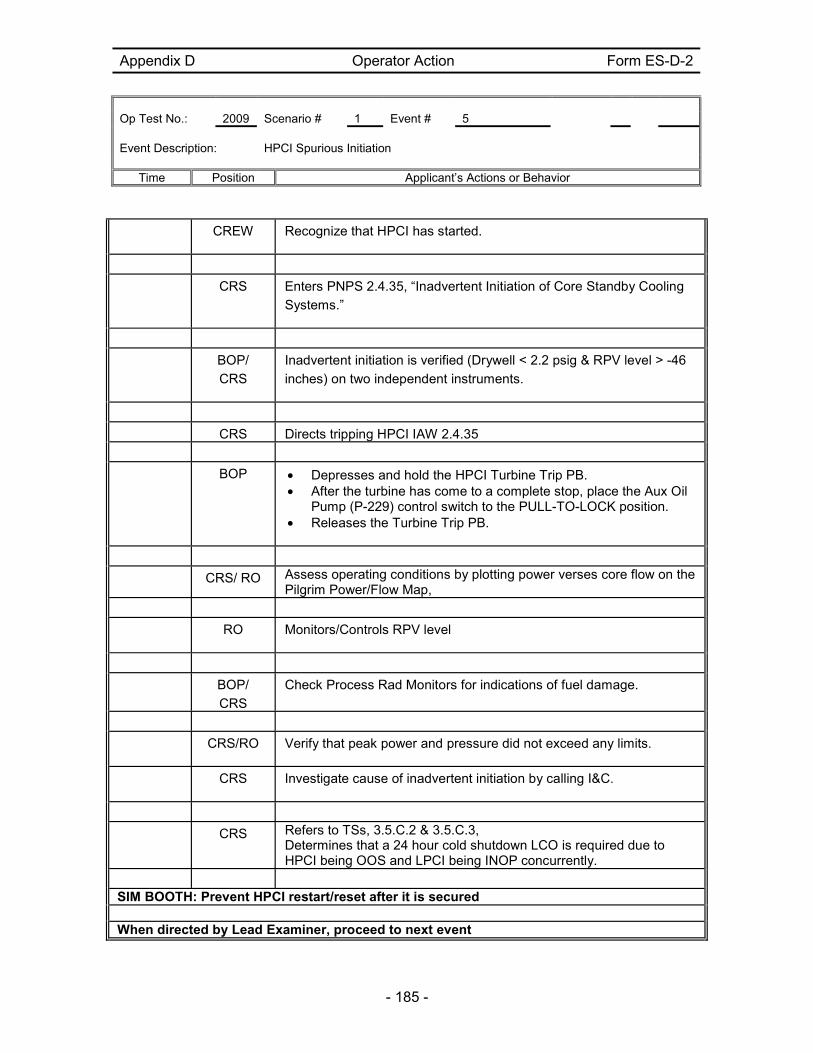
Appendix D Operator Action Form ES-D-2
Op Test No.: 2009 Scenario # 1 Event # 5 Event Description: HPCI Spurious Initiation
Time Position Applicant’s Actions or Behavior
- 185 -
CREW Recognize that HPCI has started.
CRS Enters PNPS 2.4.35, “Inadvertent Initiation of Core Standby Cooling
Systems.”
BOP/
CRS
Inadvertent initiation is verified (Drywell < 2.2 psig & RPV level > -46
inches) on two independent instruments.
CRS Directs tripping HPCI IAW 2.4.35
BOP • Depresses and hold the HPCI Turbine Trip PB. • After the turbine has come to a complete stop, place the Aux Oil
Pump (P-229) control switch to the PULL-TO-LOCK position. • Releases the Turbine Trip PB.
CRS/ RO Assess operating conditions by plotting power verses core flow on the Pilgrim Power/Flow Map,
RO Monitors/Controls RPV level
BOP/
CRS
Check Process Rad Monitors for indications of fuel damage.
CRS/RO Verify that peak power and pressure did not exceed any limits.
CRS Investigate cause of inadvertent initiation by calling I&C.
CRS Refers to TSs, 3.5.C.2 & 3.5.C.3, Determines that a 24 hour cold shutdown LCO is required due to HPCI being OOS and LPCI being INOP concurrently.
SIM BOOTH: Prevent HPCI restart/reset after it is secured When directed by Lead Examiner, proceed to next event

Appendix D Operator Action Form ES-D-2
Op Test No.: 2009 Scenario # 1 Event # 7, 8 Event Description: 7. Recirc leak in Drywell leads to Emergency Depressurization on low
RPV level.
8. MO-1001-29B LPCI Injection Valve #2 fails to auto open
Time Position Applicant’s Actions or Behavior
- 186 -
NOTE: LOOP occurs about 30 seconds after initial ALARMS
RO Recognize/report reactor scram and Loss of all Offsite power
CRS
Directs mode switch taken to SHUTDOWN and perform action of PNPS 2.1.6.
RO Place mode switch in shutdown and enter PNPS 2.1.6.
RO Verify and announce the status of APRM downscales.
RO Verify all control rods are fully inserted.
RO
Insert IRM and SRM detectors, select two SRMs for recording, and place selector switch for APRM/IRM to “IRM”.
RO Verify reactor recirc pumps at minimum speed.
RO Verify trip of the turbine.
CRS
Direct (initially) reactor water level control using RCIC. Expected band +20 to +40 inches.
CRS Direct reactor pressure 900 to 1050 psig with SRVs.
ANY Determines that a loss of Off Site power has occurred.
BOP/RO Report EOP-01 entry conditions.
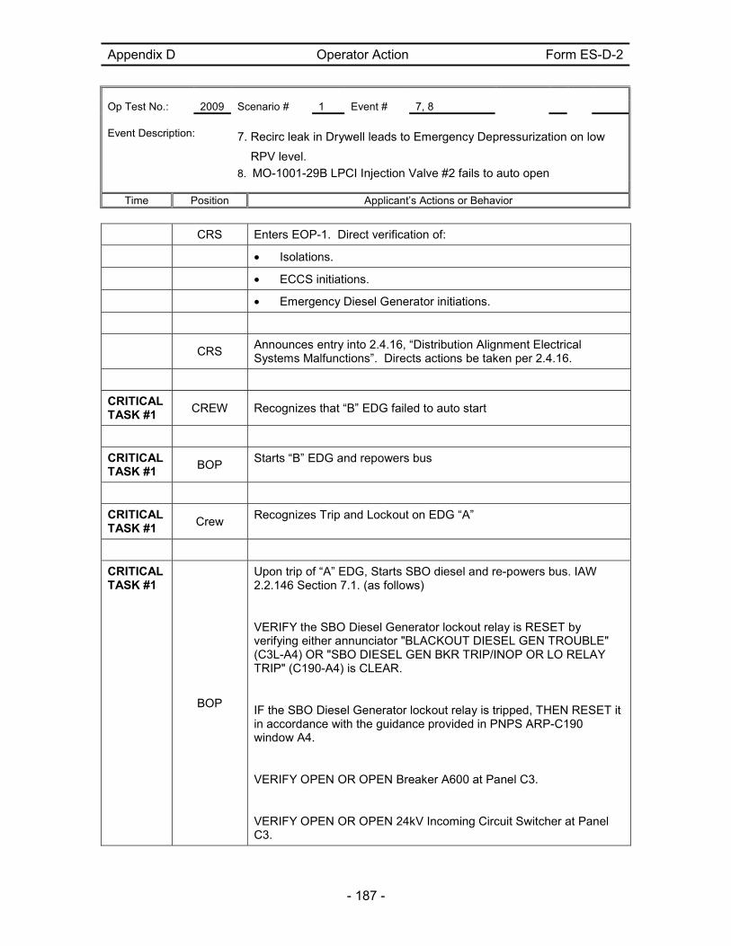
Appendix D Operator Action Form ES-D-2
Op Test No.: 2009 Scenario # 1 Event # 7, 8 Event Description: 7. Recirc leak in Drywell leads to Emergency Depressurization on low
RPV level.
8. MO-1001-29B LPCI Injection Valve #2 fails to auto open
Time Position Applicant’s Actions or Behavior
- 187 -
CRS Enters EOP-1. Direct verification of:
• Isolations.
• ECCS initiations.
• Emergency Diesel Generator initiations.
CRS
Announces entry into 2.4.16, “Distribution Alignment Electrical Systems Malfunctions”. Directs actions be taken per 2.4.16.
CRITICAL TASK #1
CREW Recognizes that “B” EDG failed to auto start
CRITICAL TASK #1
BOP Starts “B” EDG and repowers bus
CRITICAL TASK #1
Crew Recognizes Trip and Lockout on EDG “A”
CRITICAL TASK #1
BOP
Upon trip of “A” EDG, Starts SBO diesel and re-powers bus. IAW 2.2.146 Section 7.1. (as follows)
VERIFY the SBO Diesel Generator lockout relay is RESET by verifying either annunciator "BLACKOUT DIESEL GEN TROUBLE" (C3L-A4) OR "SBO DIESEL GEN BKR TRIP/INOP OR LO RELAY TRIP" (C190-A4) is CLEAR.
IF the SBO Diesel Generator lockout relay is tripped, THEN RESET it in accordance with the guidance provided in PNPS ARP-C190 window A4.
VERIFY OPEN OR OPEN Breaker A600 at Panel C3.
VERIFY OPEN OR OPEN 24kV Incoming Circuit Switcher at Panel C3.

Appendix D Operator Action Form ES-D-2
Op Test No.: 2009 Scenario # 1 Event # 7, 8 Event Description: 7. Recirc leak in Drywell leads to Emergency Depressurization on low
RPV level.
8. MO-1001-29B LPCI Injection Valve #2 fails to auto open
Time Position Applicant’s Actions or Behavior
- 188 -
VERIFY TRIPPED OR TRIP Shutdown XFMR Breaker A802 on Panel C3.
CHECK the Shutdown Transformer lockout relay on Panel C5.
IF the Shutdown Transformer lockout relay has tripped, EXAMINE the Shutdown Transformer protective relaying on Panel C5 for dropped targets. IF the negative sequence relay was the cause of the trip (as indicated by no dropped targets), and THEN RESET the lockout relay. IF the trip was caused by any other relay, a fault could exist on the bus work that will be powered by the SBODG. DO NOT RESET the lockout relay. REFER TO PNPS 1.3.11, "Reset of Lock-out Relays and Protective Relay Targets." PLACE the BLACKOUT DIESEL GENERATOR START control switch to "START" on Panel C3. WAIT 30 seconds, AND THEN PLACE the control switch for BLACKOUT DIESEL GENERATOR Breaker A801 to "CLOSE" on Panel C3. At Panel C903, PLACE the control switches for RHR Pumps "A" and "C" to the "PULL-TO-LOCK" position. At Panel C903, PLACE the control switch for Core Spray Pump "A" to the "PULL-TO-LOCK" position. At Panel C3, PLACE the control switch for Shutdown Transformer Breaker A601 to the "PULL-TO-LOCK" position. At Panel C3, SIMULTANEOUSLY DEPRESS the Load Shed Manual Initiation Channel "A" push buttons for 5 seconds.
CLOSE OR VERIFY CLOSED Breaker A600 at Panel C3. VERIFY that the SBODG has come up to rated voltage (4160V) as indicated on Shutdown Transformer voltmeter Panel C3. IF NOT, OPEN Breaker A600 at Panel C3. For the bus to be loaded, CLOSE OR VERIFY CLOSED the Shutdown Transformer Breaker A501 (A601).

Appendix D Operator Action Form ES-D-2
Op Test No.: 2009 Scenario # 1 Event # 7, 8 Event Description: 7. Recirc leak in Drywell leads to Emergency Depressurization on low
RPV level.
8. MO-1001-29B LPCI Injection Valve #2 fails to auto open
Time Position Applicant’s Actions or Behavior
- 189 -
NOTE: Station Blackout Diesel Load is monitored on the Shutdown Transformer MWe Indication at panel C3LC. Diesel is sized for one ECCS pump (2000 KW)
EXAMINER NOTE: Critical Task #1 is to ensure at least one of the 2 vital buses is powered
EXAMINER NOTE: The next event will be inserted after SBODG starts OR if SBODG is not started within 10 minutes of trip of EDG ‘A’
Examiner Note: The following steps address actions required for controlling Primary Containment Parameters
BOP/RO Recognize/announce rising drywell parameters
CRS Recognize/announce EOP-03 entry on High DW pressure
RO/BOP Report to the CRS when out of current RPV level/pressure band.
CRS
Establish new pressure bands as the reactor depressurizes due to the leak.
CRS
When Drywell temperature cannot be maintained < 150°F, directs that Drywell cooling be maximized.
Directs defeat of Drywell area cooler load shed
NOTE: Drywell area cooler load shed must be defeated.
BOP • Maximizes RBCCW on the ‘B’ loop of RBCCW.
• Maximizes Drywell cooling.
CRS
When Torus temperature cannot be maintained < 80°F, directs that Torus cooling be maximized.
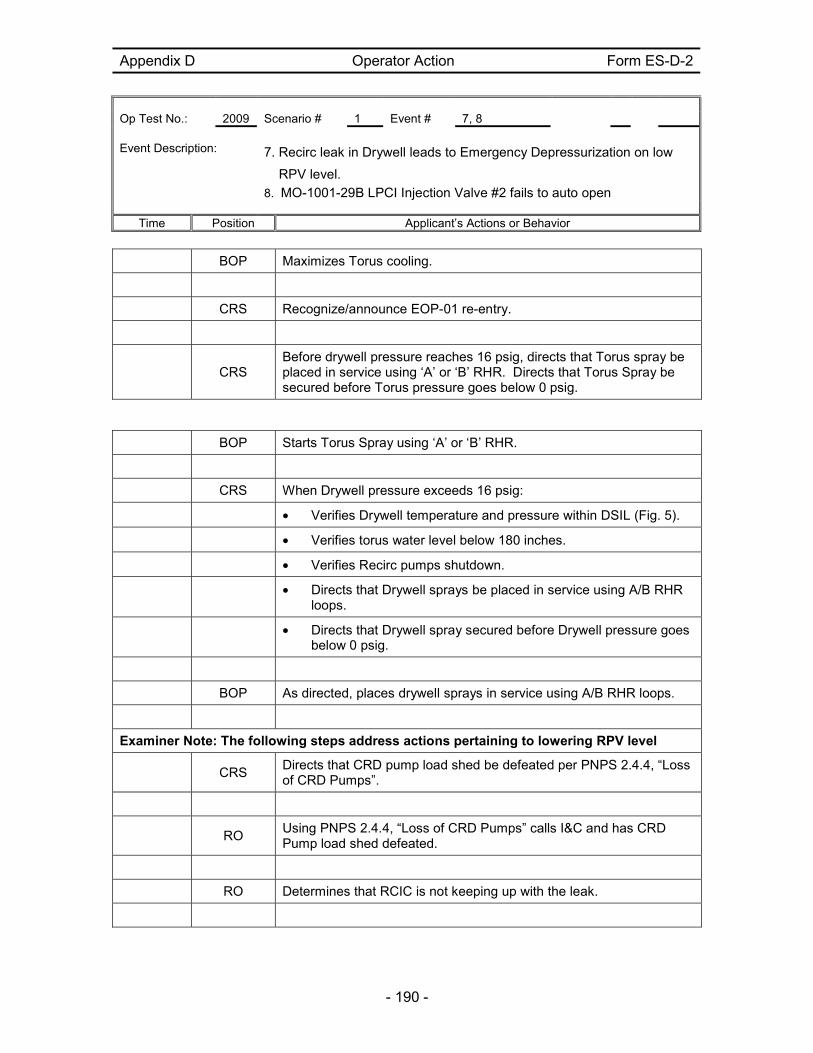
Appendix D Operator Action Form ES-D-2
Op Test No.: 2009 Scenario # 1 Event # 7, 8 Event Description: 7. Recirc leak in Drywell leads to Emergency Depressurization on low
RPV level.
8. MO-1001-29B LPCI Injection Valve #2 fails to auto open
Time Position Applicant’s Actions or Behavior
- 190 -
BOP Maximizes Torus cooling.
CRS Recognize/announce EOP-01 re-entry.
CRS
Before drywell pressure reaches 16 psig, directs that Torus spray be placed in service using ‘A’ or ‘B’ RHR. Directs that Torus Spray be secured before Torus pressure goes below 0 psig.
BOP Starts Torus Spray using ‘A’ or ‘B’ RHR.
CRS When Drywell pressure exceeds 16 psig:
• Verifies Drywell temperature and pressure within DSIL (Fig. 5).
• Verifies torus water level below 180 inches.
• Verifies Recirc pumps shutdown.
• Directs that Drywell sprays be placed in service using A/B RHR
loops.
• Directs that Drywell spray secured before Drywell pressure goes
below 0 psig.
BOP As directed, places drywell sprays in service using A/B RHR loops.
Examiner Note: The following steps address actions pertaining to lowering RPV level
CRS
Directs that CRD pump load shed be defeated per PNPS 2.4.4, “Loss of CRD Pumps”.
RO
Using PNPS 2.4.4, “Loss of CRD Pumps” calls I&C and has CRD Pump load shed defeated.
RO Determines that RCIC is not keeping up with the leak.
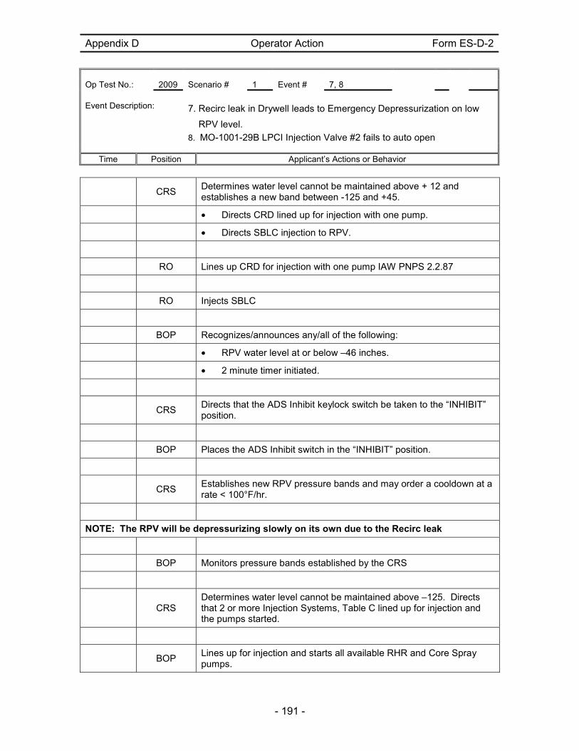
Appendix D Operator Action Form ES-D-2
Op Test No.: 2009 Scenario # 1 Event # 7, 8 Event Description: 7. Recirc leak in Drywell leads to Emergency Depressurization on low
RPV level.
8. MO-1001-29B LPCI Injection Valve #2 fails to auto open
Time Position Applicant’s Actions or Behavior
- 191 -
CRS
Determines water level cannot be maintained above + 12 and establishes a new band between -125 and +45.
• Directs CRD lined up for injection with one pump.
• Directs SBLC injection to RPV.
RO Lines up CRD for injection with one pump IAW PNPS 2.2.87
RO Injects SBLC
BOP Recognizes/announces any/all of the following:
• RPV water level at or below –46 inches.
• 2 minute timer initiated.
CRS
Directs that the ADS Inhibit keylock switch be taken to the “INHIBIT” position.
BOP Places the ADS Inhibit switch in the “INHIBIT” position.
CRS
Establishes new RPV pressure bands and may order a cooldown at a rate < 100°F/hr.
NOTE: The RPV will be depressurizing slowly on its own due to the Recirc leak
BOP Monitors pressure bands established by the CRS
CRS
Determines water level cannot be maintained above –125. Directs that 2 or more Injection Systems, Table C lined up for injection and the pumps started.
BOP
Lines up for injection and starts all available RHR and Core Spray pumps.
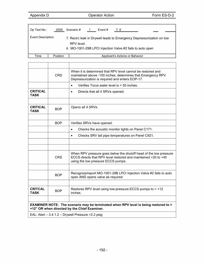
Appendix D Operator Action Form ES-D-2
Op Test No.: 2009 Scenario # 1 Event # 7, 8 Event Description: 7. Recirc leak in Drywell leads to Emergency Depressurization on low
RPV level.
8. MO-1001-29B LPCI Injection Valve #2 fails to auto open
Time Position Applicant’s Actions or Behavior
- 192 -
CRS
When it is determined that RPV level cannot be restored and maintained above -150 inches, determines that Emergency RPV Depressurization is required and enters EOP-17.
• Verifies Torus water level is > 50 inches.
CRITICAL TASK
• Directs that all 4 SRVs opened.
CRITICAL TASK
BOP Opens all 4 SRVs.
BOP Verifies SRVs have opened:
• Checks the acoustic monitor lights on Panel C171.
• Checks SRV tail pipe temperatures on Panel C921.
CRS
When RPV pressure goes below the shutoff head of the low pressure ECCS directs that RPV level restored and maintained +20 to +40 using the low pressure ECCS pumps.
BOP
Recognize/report MO-1001-29B LPCI Injection Valve #2 fails to auto open AND opens valve as required
CRITCAL TASK
BOP Restores RPV level using low-pressure ECCS pumps to > +12 inches.
EXAMINER NOTE: The scenario may be terminated when RPV level is being restored to > +12” OR when directed by the Chief Examiner.
EAL: Alert – 3.4.1.2 – Drywell Pressure >2.2 psig

Scenario Event Description
NRC Scenario 2
- 193 -
Facility: PILGRIM Scenario No.: 2 Op Test No.: 2009 NRC
Examiners: Operators: SRO -
RO -
BOP -
Initial Conditions: • Power is ~3.5 % reactor pressure ~ 960 psig
• APRM C is bypassed while I & C replaces a power supply.
• RHR Pump ‘B’ OOS for maintenance – Day 1 of a 7 day LCO has been entered.
• RM-1705-3B Log Rad Monitor is tagged and is Out of Service.
Turnover: • Place RWCU in service. RWCU was previously removed from service due to a filter demin holding pump trip. Filter demins have been backwashed and precoated. PNPS 2.2.83 Section 7.2 is complete through Step [4]. Continue at Step [5].
• After RWCU is in service, continue the startup at PNPS 2.1.1 Step [103]
Critical Tasks: 1. Upon failure of RPS & Mode Switch, Actuates ARI to insert control rods
2. Emergency depressurizes when Torus Bottom Pressure cannot be maintained
below PSP.
3. Performs Alternate RPV depressurization actions per Table T of EOP-17 when 4
SRVs do not open from the control room.
Event No.
Malf. No. Event Type*
Event Description
1 N – BOP N - SRO
Place RWCU in service
PNPS 2.2.83, Section 7.2
2 R – RO R - SRO
Continue withdrawing control rods to raise power
3 RD09 – Control Rod 46-15 stuck
C – RO C - SRO
Stuck Rod - 46-15
AOP 2.4.11.1, Att.1 – CRD System Malfunctions
Frees the stuck control rod after drive pressure is raised.

Scenario Event Description
NRC Scenario 2
- 194 -
4 RM-02 - RM-1705-3A Detector Fails
TS-SRO Air Ejector Off-Gas Process rad monitor RM-1705-3A Fails
ANN 600R-C4
TS- ODCM 3.1-2 Action 4
5
PC-2 - RWCU system leak
PC-15 – MO-1201-5 auto isolation failure
C - BOP C - SRO
RWCU isolates due to leak, outboard supply isolation valve fails to auto close and must be manually closed from control room.
ANN C904RC-C2 – NON REGEN HX OUTLET TEMP HI
ANN C904RC-A1 – RWCU Isolated
EOP-4 entry
AOP 2.4.27 – RWCU Malfunctions
6 ED19-
Y-3 Failure
Insert next event after TS and secondary containment are addressed.
I - BOP I - SRO TS - SRO
Loss of power to Y-3
AOP 5.3.18 – Loss of 120VAC Y-3
ANN C905L-B5 – Division 1 Panel Trouble
TS 3.5.A – Cold Shutdown within 24 hours
3.9.A, 3.9.B
7 RP13,14 – RPS A & B
Scram Failure Auto & Complete
Insert next event once EOP-2 is exited
C – RO C - SRO
A loss of Turbine Lube oil will occur requiring a reactor scram. When the reactor is scrammed a failure of RPS PB & Mode Switch occurs. ARI functions.
EOP-1 (in-out-in), EOP-2 (in-out)
8 MS17 – Safety Valve 4A Leak – 15 minute ramp to max severity
PC21 – DW Downcomer Leak – Initially at demanded value of 7.0 and ramped to max severity over 15 minutes
M - All Leaking Safety Valve, Downcomer break, Containment parameters degrade, ED required.
EOP-3 entries
9 MS15 – SRV 3C fails to open
C – BOP C - SRO
ALL SRVs do not open during ED, Alternate Depressurization Required
* (N)ormal, (R)eactivity, (I)nstrument, (C)omponent, (M)ajor

Scenario Event Description
NRC Scenario 2
- 195 -
Pilgrim 2009 NRC Scenario #2 The plant is at 3.5% power with reactor pressure approximately 960 psig and a startup is in progress IAW PNPS Startup procedure 2.1.1. After assuming the watch, the BOP will place RWCU in service IAW plant operating procedures. Once the startup continues, as the RO is withdrawing control rods, CR 46-15 will become stuck. The RO will enter the AOP and take actions to free the stuck control rod. Once the startup continues, an Air Ejector Off-Gas Process rad monitor will fail requiring the SRO to enter TS-ODCM 3.1.2 Action 4. Once TSs are addressed, a RWCU leak will occur and the system will not fully isolate. The BOP will take action to isolate the system per the AOP. The SRO will enter EOP-04.
Next a loss of 120 VAC Y-3 will occur. The crew will enter the AOP and take actions which include initiating a Reactor Building Isolation Signal and placing Standby Gas Treatment in service. Additionally, the SRO will enter Technical Specifications and determine the most limiting TS LCO is being in Cold Shutdown within 24 hours. After the loss of Y-3 has been addressed, a trip of the aux oil pumps will result in a loss of turbine lube oil causing the Turbine Bypass Valves to close and a loss of pressure control. RPS will fail to automatically trip and cannot be tripped manually. However the control rods will fully insert when the RO manually initiates ARI (Critical Task). The SRO will enter EOP-01 due to the scram. Following the scram, a leaking SRV and downcomer break will result in a loss of pressure suppression capability. Containment pressure will rise requiring EOP-03 entry. As torus bottom pressure rises drywell sprays will be required. Eventually containment pressure will exceed the pressure suppression pressure of EOP-03 requiring an emergency depressurization. The crew is expected to emergency depressurize (ED) the reactor IAW EOP-17 (Critical Task). All SRVs will not open during the ED requiring Alternate Depressurization methods (Critical Task). The scenario may be terminated when the RPV is depressurized and containment parameters are improving. EAL: SAE – 3.4.1.3 – Torus Bottom Pressure cannot be maintained below PSP.

Appendix D Operator Action Form ES-D-2 Op Test No.: 2009 Scenario # 2 Event # 2 Event Description: Continue Reactor Startup
Time Position Applicant’s Actions or Behavior
- 196 -
CRS
Directs placing RWCU in service IAW PNPS 2.2.83 Section 7.2 beginning at Step [5].
BOP
Obtains and Reviews PNPS 2.2.83 Section 7.2 and places RWCU in service beginning at Step[5].
Contacts field operator to assist in placing RWCU in service
SIM BOOTH: respond as field operator that you are standing by to assist as needed for the steps below. Respond as needed when contacted by the Control Room Operator
[5] OPEN/VERIFY OPEN MO-1201-5, Outbd Isol Vlv. [6] THROTTLE SLIGHTLY OPEN MO-1201-80, Return Isol Vlv. [7] SLOWLY JOG OPEN MO-1201-2, Inbd Isol Vlv, to repressurize the RWCU System. (a) WHEN pressure, as indicated on PI-1290-9, SYSTEM PRESS (Panel C904), reaches Reactor pressure OR stops increasing, THEN SLOWLY JOG OPEN MO-1201-2, Inbd Isol Vlv, until fully open. (b) At Panel C1279, LOWER FC-1279-15A (FC-1279-15B) control switch to the minimum setting AND VERIFY FV-1279-15A (FV-1279-15B), RWCU Filter/Demin T-216A (B) Effluent Valve, is CLOSED.
[8] START a Cleanup Recirculation Pump (P-204A/P-204B) [9] VERIFY/PLACE the "HOLD/FILTER" switch in the "FILTER" position. [10] COORDINATE activities to perform simultaneously: SLOWLY JOG OPEN MO-1201-80; SLOWLY PLACE FC-1279-15A (FC-1279-15B) control switch in service to achieve 111 GPM. (a) CHECK FI-1290-30A (B) for filter flow increase. [11] IF filter flow does NOT increase, THEN STOP the pump AND CHECK for isolated filters. WHEN a filter has been precoated AND pressurized, THEN PROCEED AGAIN beginning with Step 7.2[4].
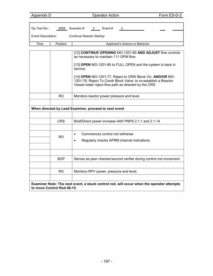
Appendix D Operator Action Form ES-D-2 Op Test No.: 2009 Scenario # 2 Event # 2 Event Description: Continue Reactor Startup
Time Position Applicant’s Actions or Behavior
- 197 -
[12] CONTINUE OPENING MO-1201-80 AND ADJUST flow controls as necessary to maintain 111 GPM flow. [13] OPEN MO-1201-80 to FULL OPEN and the system is back in service. [14] OPEN MO-1201-77, Reject to CRW Block Vlv, AND/OR MO-1201-78, Reject To Condr Block Valve, to re-establish a Reactor Vessel water reject flow path as directed by the CRS.
RO Monitors reactor power pressure and level.
When directed by Lead Examiner, proceed to next event
CRS Brief/Direct power increase IAW PNPS 2.1.1 and 2.1.14
RO
• Commences control rod withdraw
• Regularly checks APRM channel indications.
BOP Serves as peer checker/second verifier during control rod movement.
RO Monitors RPV power, pressure and level.
Examiner Note: The next event, a stuck control rod, will occur when the operator attempts to move Control Rod 46-15.

Appendix D Operator Action Form ES-D-2 Op Test No.: 2009 Scenario # 2 Event # 3 Event Description: Stuck Control Rod - 46-15
Time Position Applicant’s Actions or Behavior
- 198 -
RO
While increasing reactor power with control rods, recognizes rod 46-15 is stuck and informs CRS.
CRS Directs entry to AOP 2.4.11.1 – CRD SYSTEM MALFUNCTIONS
RO
Refers to AOP 2.4.11.1. Att.1
• ATTEMPTS TO MOVE the control rod one notch in the direction specified by the Procedure in use when the degraded control rod motion was identified.
• Ensures Control Rod 46-15 is selected
• Increases drive water pressure in approximately 50 psi increments attempting to move the drive after each increment.
EXAMINER NOTE: The control rod will move after the second increase in drive pressure
• Once the control rod has moved, RETURNs the drive water pressure to normal (approximately 250 psig above Reactor pressure).
CRS ENSUREs a Condition Report is submitted to document the event.
RO Continues with reactor startup as directed by the CRS
When directed by Lead Examiner, proceed to next event

Appendix D Operator Action Form ES-D-2 Op Test No.: 2009 Scenario # 2 Event # 4 Event Description: Air Ejector Off-Gas Process rad monitor RM-1805-3A Fails
Time Position Applicant’s Actions or Behavior
- 199 -
SIM BOOTH: RM-1805-3B NUMAC is tagged – indications are as read.
CREW
Responds to Annunciator 600R-C4 - PRE-TREATMENT RAD MONITOR DNSCL/INOP
CRS
Directs Checking Log Rad Monitors 1805-3A, B on Panel C910
BOP
Check Log Rad Monitors 1805-3A, B on Panel C910 and determines 1805-3A has failed.
Informs CRS
CRS
Refers to ODCM Table 3.1-2, Action 4 – releases may continue for up to 72 hours as long as the augmented offgas system is not bypassed and the downstream post treatment rad monitor is operable
When directed by Lead Examiner, proceed to next event

Appendix D Operator Action Form ES-D-2 Op Test No.: 2009 Scenario # 2 Event # 5 Event Description: RWCU isolates due to leak, outboard isolation valve fails to auto close
and must be manually closed from control room.
Time Position Applicant’s Actions or Behavior
- 200 -
CREW
Responds to and acknowledges:
ANN C904RC-C2 – NON REGEN HX OUTLET TEMP HI
ANN C904RC-A1 – RWCU Isolated
CRS
Directs Response IAW ARP & Directs entry to AOP 2.4.27 – RWCU Malfunctions
Verify RWCU MO-1201-2, RWCU INBD ISOL VALVE. AND MO-1201-5, RWCU OUTBD ISOL VALVE have closed.
BOP
Observes RWCU MO-1201-2 and MO-1201-5 have failed to close.
CLOSES MO-1201-2 AND MO-1201-5 and informs CRS of auto close failure.
CRS
Enters to EOP-04 on Rx Bldg Vent Rad Hi
Ensures RWCU is isolated
SIM BOOTH: If contacted by control room to report field status, state that all coolers are in service and the quads are dry
Examiner Note: When leak is isolated and when directed by Lead Examiner, proceed to next event
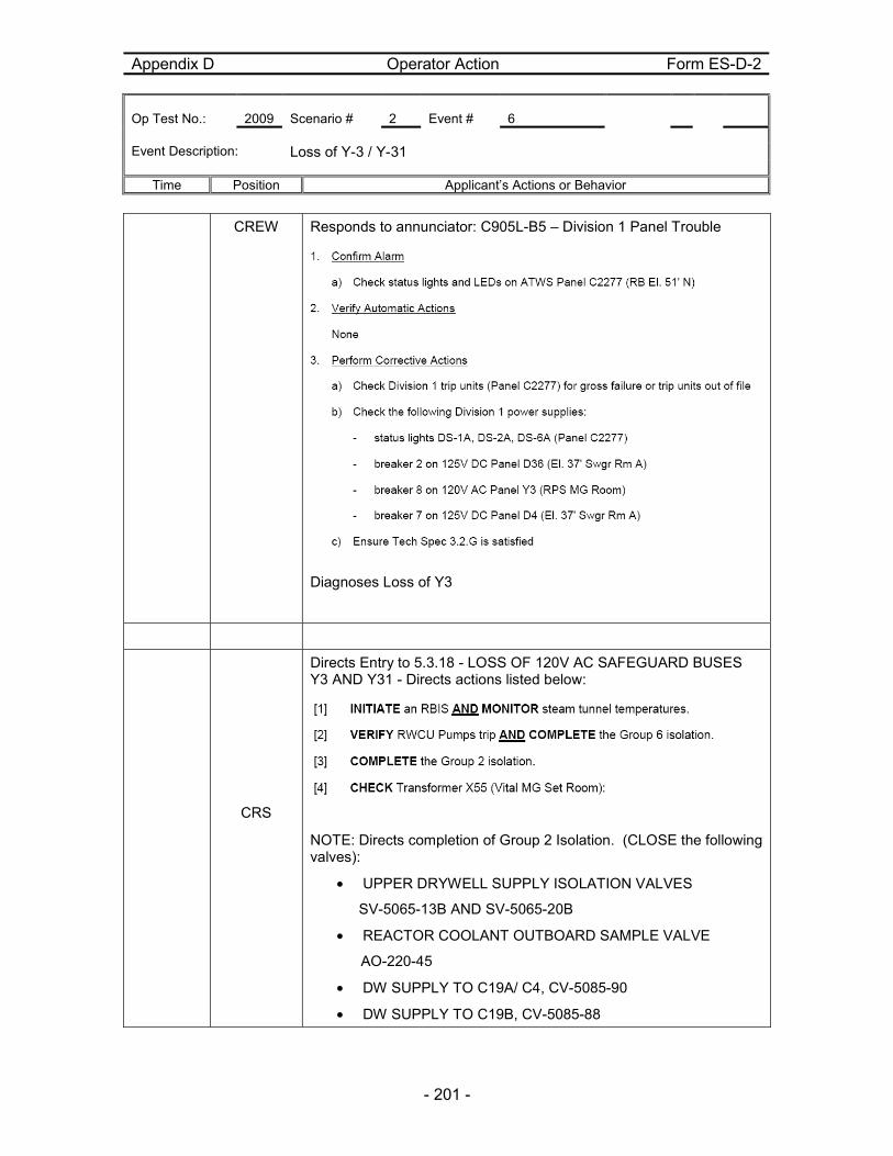
Appendix D Operator Action Form ES-D-2 Op Test No.: 2009 Scenario # 2 Event # 6 Event Description: Loss of Y-3 / Y-31
Time Position Applicant’s Actions or Behavior
- 201 -
CREW
Responds to annunciator: C905L-B5 – Division 1 Panel Trouble
Diagnoses Loss of Y3
CRS
Directs Entry to 5.3.18 - LOSS OF 120V AC SAFEGUARD BUSES Y3 AND Y31 - Directs actions listed below:
NOTE: Directs completion of Group 2 Isolation. (CLOSE the following valves):
• UPPER DRYWELL SUPPLY ISOLATION VALVES
SV-5065-13B AND SV-5065-20B
• REACTOR COOLANT OUTBOARD SAMPLE VALVE
AO-220-45
• DW SUPPLY TO C19A/ C4, CV-5085-90
• DW SUPPLY TO C19B, CV-5085-88

Appendix D Operator Action Form ES-D-2 Op Test No.: 2009 Scenario # 2 Event # 6 Event Description: Loss of Y-3 / Y-31
Time Position Applicant’s Actions or Behavior
- 202 -
• C19/C41 RETURN ISOL VALVE, CV-5065-92
RO Monitors power, pressure and level
BOP
Initiates an RBIS
Completes the Group 2 isolations as required
Dispatches field operator to check Transformer X55
SIM BOOTH: When contacted by control room, acknowledge request to check out the status of transformer X55
CRS
Contacts WWM to investigate loss of Y3
Determines that Cold Shutdown within 24 hours is required based on multiple INOPERABLE systems due to loss of power to system components.
NOTE: PNPS 5.3.18, Loss of 120VAC Safeguard buses Y-3 and Y-31, Section 5.0 lists equipment which has lost power.
When TS are addressed, continue with next event.

Appendix D Operator Action Form ES-D-2 Op Test No.: 2009 Scenario # 2 Event # 7 Event Description: A loss of Turbine Lube oil will occur and bypass valves close requiring a
reactor scram. When the reactor is scrammed a failure of RPS manual scram PBs & Mode Switch to Shutdown occurs. ARI functions.
Time Position Applicant’s Actions or Behavior
- 203 -
CREW
Recognizes a loss of the turbine lube oil aux oil pump and closure of the Turbine Bypass valves.
CRS Directs reactor scram due to loss of pressure control
RO • Depresses both manual scram pushbuttons
• Places mode switch in shutdown and enter PNPS 2.1.6.
RO Recognize/report failure to scram.
CRS
Enters EOP-01 and immediately transitions to EOP-02 based on all controls rods not at or beyond position 02.
RO Performs the following actions:
• Verifies mode switch in “SHUTDOWN”.
CRITICAL TASK
• Accomplishes reactor scram with either channel of ARI.
• Recognizes all control rods are inserted fully informs CRS
CRS
Exits EOP-02 and re-enters EOP-01 based on all controls rods inserted to or beyond position 02.
RO
Insert IRM and SRM detectors, select two SRMs for recording, and place selector switch for APRM/IRM to “IRM”.
RO Verify reactor recirc pumps at minimum speed.
RO Verify trip of the turbine.
CRS Direct verification of:
• Isolations

Appendix D Operator Action Form ES-D-2 Op Test No.: 2009 Scenario # 2 Event # 7 Event Description: A loss of Turbine Lube oil will occur and bypass valves close requiring a
reactor scram. When the reactor is scrammed a failure of RPS manual scram PBs & Mode Switch to Shutdown occurs. ARI functions.
Time Position Applicant’s Actions or Behavior
- 204 -
• ECCS initiations.
• Emergency Diesel Generator initiations.
CRS Direct reactor water level +20 - +40.
CRS Direct reactor pressure band of 900 to 1050 psig with HPCI/RCIC.
Examiner Note: The next event will occur once the CRS exits EOP-02 and a RPV level and pressure band are directed.
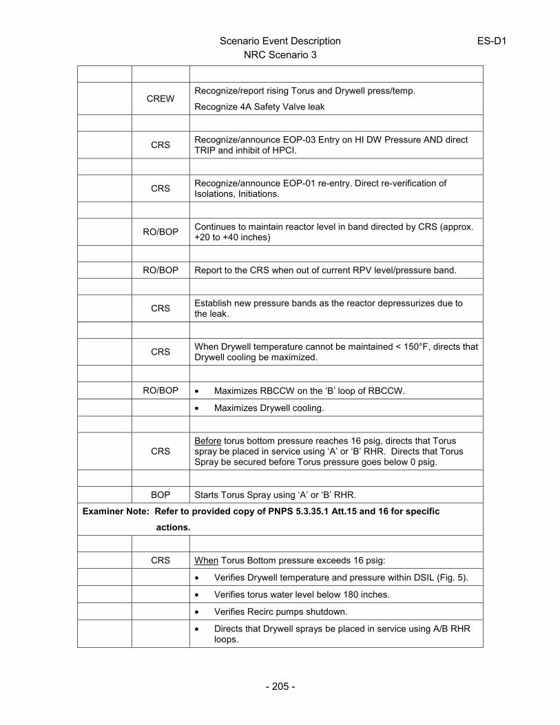
Scenario Event Description ES-D1 NRC Scenario 3
- 205 -
CREW
Recognize/report rising Torus and Drywell press/temp.
Recognize 4A Safety Valve leak
CRS
Recognize/announce EOP-03 Entry on HI DW Pressure AND direct TRIP and inhibit of HPCI.
CRS
Recognize/announce EOP-01 re-entry. Direct re-verification of Isolations, Initiations.
RO/BOP
Continues to maintain reactor level in band directed by CRS (approx. +20 to +40 inches)
RO/BOP Report to the CRS when out of current RPV level/pressure band.
CRS
Establish new pressure bands as the reactor depressurizes due to the leak.
CRS
When Drywell temperature cannot be maintained < 150°F, directs that Drywell cooling be maximized.
RO/BOP • Maximizes RBCCW on the ‘B’ loop of RBCCW.
• Maximizes Drywell cooling.
CRS
Before torus bottom pressure reaches 16 psig, directs that Torus spray be placed in service using ‘A’ or ‘B’ RHR. Directs that Torus Spray be secured before Torus pressure goes below 0 psig.
BOP Starts Torus Spray using ‘A’ or ‘B’ RHR.
Examiner Note: Refer to provided copy of PNPS 5.3.35.1 Att.15 and 16 for specific
actions.
CRS When Torus Bottom pressure exceeds 16 psig:
• Verifies Drywell temperature and pressure within DSIL (Fig. 5).
• Verifies torus water level below 180 inches.
• Verifies Recirc pumps shutdown.
• Directs that Drywell sprays be placed in service using A/B RHR
loops.
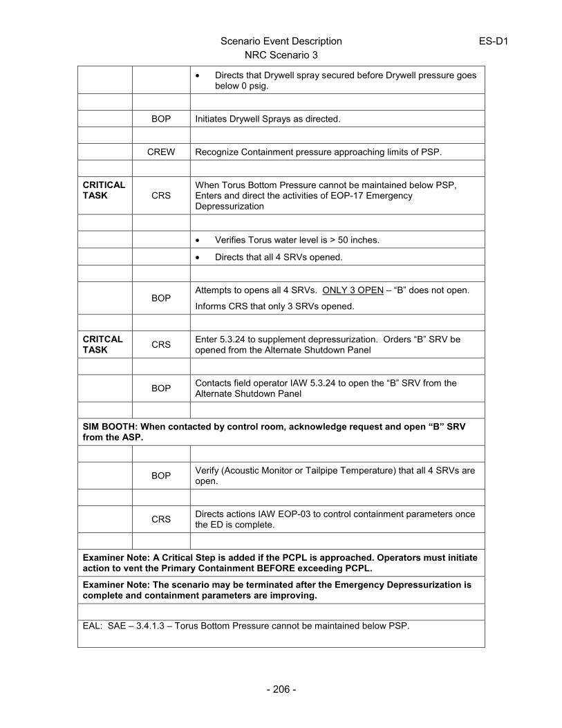
Scenario Event Description ES-D1 NRC Scenario 3
- 206 -
• Directs that Drywell spray secured before Drywell pressure goes
below 0 psig.
BOP Initiates Drywell Sprays as directed.
CREW Recognize Containment pressure approaching limits of PSP.
CRITICAL TASK CRS
When Torus Bottom Pressure cannot be maintained below PSP, Enters and direct the activities of EOP-17 Emergency Depressurization
• Verifies Torus water level is > 50 inches.
• Directs that all 4 SRVs opened.
BOP
Attempts to opens all 4 SRVs. ONLY 3 OPEN – “B” does not open.
Informs CRS that only 3 SRVs opened.
CRITCAL TASK
CRS Enter 5.3.24 to supplement depressurization. Orders “B” SRV be opened from the Alternate Shutdown Panel
BOP
Contacts field operator IAW 5.3.24 to open the “B” SRV from the Alternate Shutdown Panel
SIM BOOTH: When contacted by control room, acknowledge request and open “B” SRV from the ASP.
BOP
Verify (Acoustic Monitor or Tailpipe Temperature) that all 4 SRVs are open.
CRS
Directs actions IAW EOP-03 to control containment parameters once the ED is complete.
Examiner Note: A Critical Step is added if the PCPL is approached. Operators must initiate action to vent the Primary Containment BEFORE exceeding PCPL.
Examiner Note: The scenario may be terminated after the Emergency Depressurization is complete and containment parameters are improving.
EAL: SAE – 3.4.1.3 – Torus Bottom Pressure cannot be maintained below PSP.
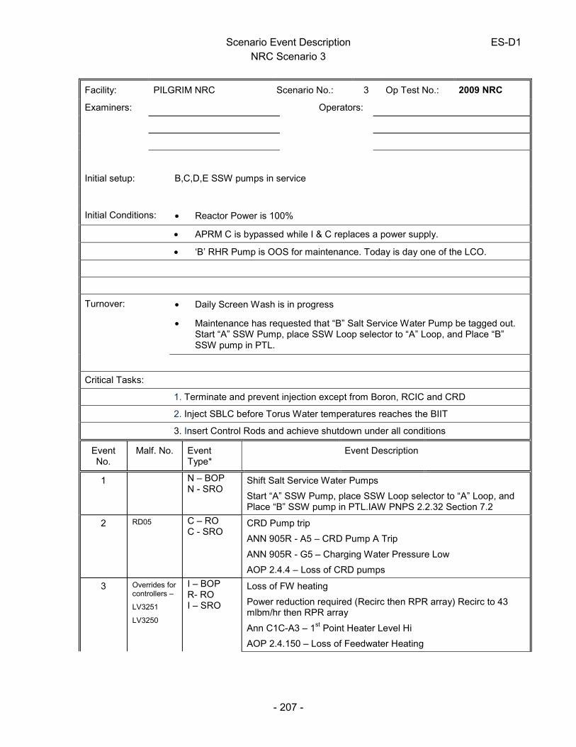
Scenario Event Description ES-D1 NRC Scenario 3
- 207 -
Facility: PILGRIM NRC Scenario No.: 3 Op Test No.: 2009 NRC
Examiners: Operators:
Initial setup: B,C,D,E SSW pumps in service
Initial Conditions: • Reactor Power is 100%
• APRM C is bypassed while I & C replaces a power supply.
• ‘B’ RHR Pump is OOS for maintenance. Today is day one of the LCO.
Turnover: • Daily Screen Wash is in progress
• Maintenance has requested that “B” Salt Service Water Pump be tagged out. Start “A” SSW Pump, place SSW Loop selector to “A” Loop, and Place “B” SSW pump in PTL.
Critical Tasks:
1. Terminate and prevent injection except from Boron, RCIC and CRD
2. Inject SBLC before Torus Water temperatures reaches the BIIT
3. Insert Control Rods and achieve shutdown under all conditions
Event No.
Malf. No. Event Type*
Event Description
1 N – BOP N - SRO
Shift Salt Service Water Pumps
Start “A” SSW Pump, place SSW Loop selector to “A” Loop, and Place “B” SSW pump in PTL.IAW PNPS 2.2.32 Section 7.2
2 RD05 C – RO C - SRO
CRD Pump trip
ANN 905R - A5 – CRD Pump A Trip
ANN 905R - G5 – Charging Water Pressure Low
AOP 2.4.4 – Loss of CRD pumps
3 Overrides for controllers –
LV3251
LV3250
I – BOP R- RO I – SRO
Loss of FW heating
Power reduction required (Recirc then RPR array) Recirc to 43 mlbm/hr then RPR array
Ann C1C-A3 – 1st Point Heater Level Hi
AOP 2.4.150 – Loss of Feedwater Heating

Scenario Event Description ES-D1 NRC Scenario 3
- 208 -
4 CW01- ‘A’ SSW pump trip
TS-SRO
“A” Salt Service Water Pump Trip
TS 3.5.B.4 – Restore SSW to operable status within 72 hours
5 RP09A – RPS MTR Gen ‘A’ Trip
RM02 - Refuel Floor Rad Monitor RM-1805-8A fails
downscale
C – ALL TS-SRO
Failure of RPS MG Set “A” requires transfer to alternate power.
Ann 905R-C1 – RPS MG Set A Trip
2.2.79 – RPS Section 7.1.5
Refuel Floor Rad Monitor RM-1805-8A fails requiring entry to TS 3.2.D.1 – no recently irridated fuel movement unless SBGT is in service
6 MS-14 – SRV 3B Fails open
LHWT (East & West SDIVs 99% full)
M-All SRV fails open, Scram required, ATWS
ANN 903L-B2, A2
AOP 2.4.29 – Stuck Open SRV
EOP1, EOP 2
7 LP01 A & B C – BOP C - SRO
SBLC fails to inject initially and then will inject (for less than one minute) after determining initial failure
* (N)ormal, (R)eactivity, (I)nstrument, (C)omponent, (M)ajor
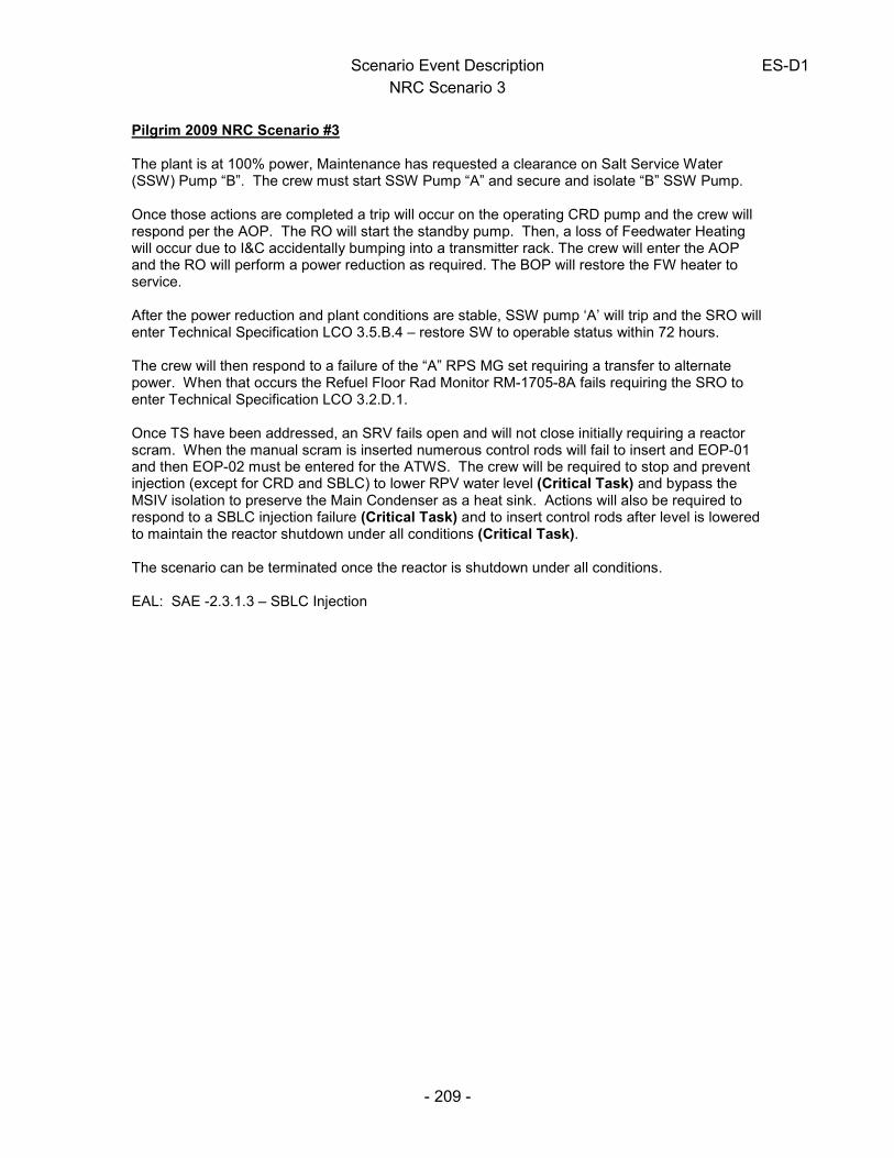
Scenario Event Description ES-D1 NRC Scenario 3
- 209 -
Pilgrim 2009 NRC Scenario #3 The plant is at 100% power, Maintenance has requested a clearance on Salt Service Water (SSW) Pump “B”. The crew must start SSW Pump “A” and secure and isolate “B” SSW Pump. Once those actions are completed a trip will occur on the operating CRD pump and the crew will respond per the AOP. The RO will start the standby pump. Then, a loss of Feedwater Heating will occur due to I&C accidentally bumping into a transmitter rack. The crew will enter the AOP and the RO will perform a power reduction as required. The BOP will restore the FW heater to service. After the power reduction and plant conditions are stable, SSW pump ‘A’ will trip and the SRO will enter Technical Specification LCO 3.5.B.4 – restore SW to operable status within 72 hours. The crew will then respond to a failure of the “A” RPS MG set requiring a transfer to alternate power. When that occurs the Refuel Floor Rad Monitor RM-1705-8A fails requiring the SRO to enter Technical Specification LCO 3.2.D.1. Once TS have been addressed, an SRV fails open and will not close initially requiring a reactor scram. When the manual scram is inserted numerous control rods will fail to insert and EOP-01 and then EOP-02 must be entered for the ATWS. The crew will be required to stop and prevent injection (except for CRD and SBLC) to lower RPV water level (Critical Task) and bypass the MSIV isolation to preserve the Main Condenser as a heat sink. Actions will also be required to respond to a SBLC injection failure (Critical Task) and to insert control rods after level is lowered to maintain the reactor shutdown under all conditions (Critical Task). The scenario can be terminated once the reactor is shutdown under all conditions. EAL: SAE -2.3.1.3 – SBLC Injection

Appendix D Operator Action Form ES-D-2
Op Test No.: 2009 Scenario # 3 Event # 1 Event Description: Shift Salt Service Water Pumps IAW Section 7.2 of PNPS 2.2.32
Time Position Applicant’s Actions or Behavior
- 210 -
CRS Direct shifting SSW Loop selector to “A” Loop and SSW Pumps IAW Sect 7.2 of PNPS 2.2.32
BOP Reviews procedure and Starts the “A” SSW pump
BOP Monitors SSW System and verify pressures stabilize
BOP Stops the ”B” SSW pump. Places SSW Loop Selector to Position “A” and places the handswitch for SSW pump “B” in PTL
SIM BOOTH: Provide Tags when requested.
When directed by Lead Examiner, proceed to next event

Appendix D Operator Action Form ES-D-2
Op Test No.: 2009 Scenario # 3 Event # 2 Event Description: CRD Pump Trip
Time Position Applicant’s Actions or Behavior
- 211 -
RO
Acknowledges/announces trip of ‘A’ CRD pump.
Refers to the following annunciator responses:
• ANN 905R - A5 – CRD Pump A Trip
• ANN 905R - G5 – Charging Water Pressure Low
Informs CRS of CRD pump “A” trip
CRS Directs entry into PNPS 2.4.4. – Loss of CRD Pumps
RO
Checks power, pressure, level. Performs immediate actions of PNPS 2.4.4:
• Notes pressure greater than 950 psig.
• No inoperable accumulator alarms.
CRS
Directs RO to start standby CRD pump IAW with PNPS 2.4.4.
Contacts WWM to investigate pump trip
RO • Transfers FCV to manual and closes.
• Starts ‘B’ CRD pump.
• Verifies pump amp and discharge pressure stabilize.
• Balances deviation meter.
• Transfers CRD controller to AUTO.
When directed by Lead Examiner, proceed to next event
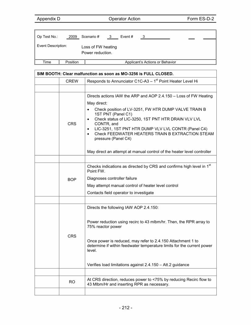
Appendix D Operator Action Form ES-D-2
Op Test No.: 2009 Scenario # 3 Event # 3 Event Description: Loss of FW heating
Power reduction.
Time Position Applicant’s Actions or Behavior
- 212 -
SIM BOOTH: Clear malfunction as soon as MO-3256 is FULL CLOSED.
CREW Responds to Annunciator C1C-A3 – 1st Point Heater Level Hi
CRS
Directs actions IAW the ARP and AOP 2.4.150 – Loss of FW Heating
May direct:
• Check position of LV-3251, FW HTR DUMP VALVE TRAIN B 1ST PNT (Panel C1)
• Check status of LIC-3250, 1ST PNT HTR DRAIN VLV LVL CONTR, and
• LIC-3251, 1ST PNT HTR DUMP VLV LVL CONTR (Panel C4) • Check FEEDWATER HEATERS TRAIN B EXTRACTION STEAM
pressure (Panel C4)
May direct an attempt at manual control of the heater level controller
BOP
Checks indications as directed by CRS and confirms high level in 1st Point FW.
Diagnoses controller failure
May attempt manual control of heater level control
Contacts field operator to investigate
CRS
Directs the following IAW AOP 2.4.150:
Power reduction using recirc to 43 mlbm/hr. Then, the RPR array to 75% reactor power
Once power is reduced, may refer to 2.4.150 Attachment 1 to determine if within feedwater temperature limits for the current power level.
Verifies load limitations against 2.4.150 – Att.2 guidance
RO
At CRS direction, reduces power to <75% by reducing Recirc flow to 43 Mlbm/Hr and inserting RPR as necessary.

Appendix D Operator Action Form ES-D-2
Op Test No.: 2009 Scenario # 3 Event # 3 Event Description: Loss of FW heating
Power reduction.
Time Position Applicant’s Actions or Behavior
- 213 -
CRS
After conditions stabilize, contacts reactor engineering for guidance due to the power reduction
SIM BOOTH: Call control room as an I&C Tech and report that you accidentally bumped into FW Htr Rack C51. No damage occurred. Your supervisor reports there is no issue with restoring the FW heater that was lost in the transient
CRS
When informed that the FW heater can be returned to service, directs the BOP to restore it IAW 2.4.150.
BOP
Restores FWH IAW 2.4.150 guidance in Att.3
When directed by Lead Examiner, proceed to next event

Appendix D Operator Action Form ES-D-2
Op Test No.: 2009 Scenario # 3 Event # 4 Event Description: “A” Salt Service Water Pump Trip.
Time Position Applicant’s Actions or Behavior
- 214 -
CREW
Respond to Trip of “A” SSW Pump. May refer to 2.4.43. Actions are in accordance with 2.2.32.
BOP Contacts field operator to investigate
SIM BOOTH: Call control room as field operator and report that screens have stopped turning and the screen wash pumps have tripped on low pressure.
When contacted to check on pump trip – report back after 1 minute an acrid odor is coming from B1541, but no signs of fire or fire damage.
CRS
Coordinates control room response and references technical specifications. Determines that TS 3.5.B.4.A.1 – Restore SSW to operable status within 72 hours applies.
RO Monitors reactor power, pressure and level
When directed by Lead Examiner, proceed to next event

Appendix D Operator Action Form ES-D-2
Op Test No.: 2009 Scenario # 3 Event # 5 Event Description: Failure of RPS MG Set “A” requires transfer to alternate power.
Refuel Floor Rad Monitor RM-1705-8A fails.
Time Position Applicant’s Actions or Behavior
- 215 -
CREW
Recognize / announce various annunciators associated with the loss of “A” RPS bus including
• Ann 905R-C1 – RPS MG Set A Trip
RO
• Diagnoses a trip of the RPS ‘A’ MG Set.
• Recognize / announce loss of A’ RPS bus.
• Recognize / announce annunciator “RPS MG Set A Trip” is in
alarm.
• Refers to ARP C905R-C1.
• Verifies ½ scram RPS Channel ‘A’
• Directs Field Operator to investigate
SIM BOOTH: Report back as Field Operator that MG Set Output Breaker and ‘A’ RPS EPA’s are tripped.
CRS
Directs that action be taken per ARP C905R-C1.
Refers to Tech Specs 3.1 and Table 3.1.1.
Direct troubleshooting/repair of RPS MG Set ‘A’.
Direct placing RPS ‘A’ on the backup power supply IAW PNPS 2.2.79.
CREW
Recognizes Refuel Floor Rad Monitor RM-1705-8A has failed.
CRS informed.
CRS
Refers to the following Tech Specs
• RPS Tech Specs 3.1 and Table 3.1.1.
• Rad Monitor - 3.2.D.1 – no recently irridated fuel movement unless SBGT is in service
When directed by Lead Examiner, proceed to next event

Scenario Event Description
NRC Scenario 4
- 216 -
ALL Identify/announce ‘B’ SRV open.
BOP Reference ARP C903L, B2. – Relief / Safety valve Open
CRS Direct entry into PNPS 2.4.29. – Stuck Open SRV
CRS Direct monitoring of Torus bulk temperature and note time.
CRS Direct BOP to attempt cycling of ‘B’ SRV switch.
BOP
Cycles ‘B’ SRV switch identifies ‘B’ SRV remains open.
Contacts field operator to place switch at ASP to close
SIM BOOTH: When contacted by control room to cycle SRV switch at ASP, acknowledge request. Report back after 1 minute that the switch was cycled.
RO As time permits, attempt to lower power
CRS Briefs requirement for manual reactor scram if ‘B’ SRV remains open.
IF Operator: After taking the ‘B’ SRV C/S to close at the ASP, report back that you have done so.
CRS
When it has been determined that the safety relief valve cannot be closed, direct a manual reactor scram.
RO • Depress both manual scram pushbuttons.
• Place mode switch in shutdown and enter PNPS 2.1.6.
RO Verify and announce the status of APRMs
RO Recognize/report failure to scram.
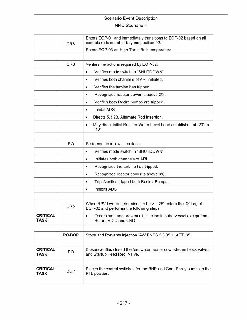
Scenario Event Description
NRC Scenario 4
- 217 -
CRS
Enters EOP-01 and immediately transitions to EOP-02 based on all controls rods not at or beyond position 02.
Enters EOP-03 on High Torus Bulk temperature.
CRS Verifies the actions required by EOP-02:
• Verifies mode switch in “SHUTDOWN”.
• Verifies both channels of ARI initiated.
• Verifies the turbine has tripped.
• Recognizes reactor power is above 3%.
• Verifies both Recirc pumps are tripped.
• Inhibit ADS
• Directs 5.3.23, Alternate Rod Insertion.
• May direct initial Reactor Water Level band established at -20” to
+10”
RO Performs the following actions:
• Verifies mode switch in “SHUTDOWN”.
• Initiates both channels of ARI.
• Recognizes the turbine has tripped.
• Recognizes reactor power is above 3%.
• Trips/verifies tripped both Recirc. Pumps.
• Inhibits ADS
CRS
When RPV level is determined to be > – 25” enters the ‘Q’ Leg of EOP-02 and performs the following steps:
CRITICAL TASK • Orders stop and prevent all injection into the vessel except from
Boron, RCIC and CRD.
RO/BOP Stops and Prevents injection IAW PNPS 5.3.35.1, ATT. 35.
CRITICAL TASK
RO Closes/verifies closed the feedwater heater downstream block valves and Startup Feed Reg. Valve.
CRITICAL TASK
BOP Places the control switches for the RHR and Core Spray pumps in the PTL position.

Scenario Event Description
NRC Scenario 4
- 218 -
RO
Start one SBLC system by placing the SLC ACTUATE switch to SYS ‘A’ or SYS ‘B’ position on Panel C905.
RO
Recognize/report that after attempting to start the first SBLC Train; the SLC pump failed to start.
CRS Direct using other train of SBLC.
CRITICAL TASK RO
Start the opposite SBLC train with the SLC ACTUATE switch.
RO Recognize/report that the second SBLC pump is running & injecting. Reports Boron tank initial level.
RO Recognize/report that the second SLC pump has tripped.
CRS
Directs RO to establish alternate means of injecting SBLC (through RWCU).
CREW Recognizes/reports SRV has CLOSED.
CRS Directs pressure band of 900-1000 psig.
RO
Enters PNPS 5.3 23, “Alternate Rod Insertion”. Determines that there is a hydraulic lock and goes to Section 3.3 of the procedure and performs it concurrently with the “General Actions” section of the procedure.
RO
When requested, I&C defeats RPS and ARI interlocks IAW PNPS 5.3.23 ATT.1 and 2.
SIM BOOTH: When requested to defeat RPS and ARI interlocks, acknowledge request then call back in 5 minutes too report they’ve been defeated.
CRS Asks the crew to report any of the following plant conditions:
• Rx power <3% (APRM downscales are in).
• RPV water level reaches –125 inches TAF.
RO Performs the following actions to reset and scram the reactor:

Scenario Event Description
NRC Scenario 4
- 219 -
• Reset the scram using the RPS reset switch.
• Places the Air Dump System Test Switch to “ISOLATE”.
• Waits for/verifies the “SPVAH Pressure Lo” alarm clears.
• Places the Air Dump System Test Switch to “NORMAL”.
• Verifies either SDIV Level Hi or SDIV East Not Drained and
SDIV West Not Drained alarms are clear.
• Initiates a manual scram.
• Verifies and announces all rods in, when achieved
CRITICAL TASK – is to insert all control rods to achieve shutdown under all conditions.
SIM BOOTH: Permit Rod Insertion (to ALL RODS FULL IN) on second manual SCRAM attempt.
CRS
When all rods are in transitions to EOP-01. Orders RPV water level be restored and maintained between +20 and +40 inches. Initiates a cooldown using HPCI or SRVs at less than 100° per hour.
BOP
Restores and maintains RPV level +20 to +40. Initiates a cooldown at less than 100° per hour.
The scenario may be terminated at the discretion of the Examiner OR when RPV level has been restored to between +20 and +40 and a cooldown has been initiated.
EAL: SAE -2.3.1.3 – SBLC Injection

Scenario Event Description
NRC Scenario 4
- 220 -
Facility: PILGRIM Scenario No.: 4 Op Test No.: 2009 NRC
Examiners: Operators: SRO -
RO -
BOP -
Initial Conditions: • Power is 100 %
• APRM C is bypassed while I & C replaces a power supply.
• RHR Pump ‘B’ OOS for maintenance – Day 1 of a 7 day LCO has been entered
Turnover: • Place SBGT “A” in service for I&C to check vibrations.
• A control rod pattern adjustment is scheduled; the crew is directed to lower power to 90 %.
Critical Task: 1. Scram the reactor before one area exceeds max safe temperature
2. Emergency Depressurize when two areas exceed max safe temp
Event No.
Malf. No. Event Type*
Event Description
1 Override AO5041B OPEN after it is opened for evolution
N – BOP N – SRO TS - SRO
Place “A” SBGT in service for vibration checks
IAW 2.2.70
TS 3.7.A.2.B – Deactivate in isolated condition – Torus Vent AO5041B fails in open position.
2 R – RO R - SRO
Lower power to 90% using Recirculation Flow
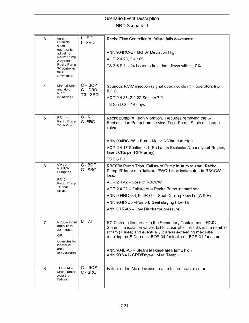
Scenario Event Description
NRC Scenario 4
- 221 -
3 Insert Override when operator is adjusting Recirc Pump A Speed - Recirc Pump ‘A’ controller fails Downscale
I – RO I - SRO
Recirc Flow Controller ‘A’ failure fails downscale.
ANN 904RC-C7 MG ‘A’ Deviation High
AOP 2.4.20, 2.4.165
TS 3.6.F.1. - 24 hours to have loop flows within 10%
4 Manual Stop and Hold RCIC initiation PB
C – BOP C – SRO TS - SRO
Spurious RCIC injection (signal does not clear) – operators trip RCIC.
AOP 2.4.35, 2.2.22 Section 7.2
TS 3.5.D.2 – 14 days
5 RR11 – Recirc Pump ‘A’ Hi Vibs
C - RO C -SRO
Recirc pump ‘A’ High Vibration. Requires removing the ‘A’ Recirculation Pump from service. Trips Pump, Shuts discharge valve
ANN 904RC-B6 – Pump Motor A Vibration High
AOP 2.4.17 Section 4.1 (End up in Exclusion/Unanalyzed Region, Insert CRs per RPR array).
TS 3.6.F.1
6 CW05-RBCCW Pump trip RR13- Recirc Pump ‘B’ seal failure
C - BOP C - SRO
RBCCW Pump Trips, Failure of Pump in Auto to start. Recirc Pump ‘B’ inner seal failure. RWCU may isolate due to RBCCW loss.
AOP 2.4.42 – Loss of RBCCW
AOP 2.4.22 – Failure of a Recirc Pump inboard seal
ANN 904RC-G6, 904R-G5 –Seal Cooling Flow Lo (A & B)
ANN 904R-D5 –Pump B Seal staging Flow Hi
ANN C1R-A5 – Low Discharge pressure
7 RC06 – initial ramp 15 in 20 minutes
OR
Overrides for individual area temperatures
M - All RCIC steam line break in the Secondary Containment, RCIC Steam line isolation valves fail to close which results in the need to scram (1 area) and eventually 2 areas exceeding max safe requiring an E-Depress. EOP-04 for leak and EOP-01 for scram
ANN 904L-A6 – Steam leakage area temp high ANN 903-A1- CRD/Drywell Misc Temp Hi
8 TFU-114 – Main Turbine Auto trip Failure
C – BOP C - SRO
Failure of the Main Turbine to auto trip on reactor scram.

Scenario Event Description
NRC Scenario 4
- 222 -
* (N)ormal, (R)eactivity, (I)nstrument, (C)omponent, (M)ajor

Scenario Event Description
NRC Scenario 4
- 223 -
Pilgrim 2009 NRC Scenario #4 The plant is at 100% power. The crew will place SBGT “A” in service for I&C vibration checks. As the lineup for the evolution is being secured, a primary containment isolation damper will fail to close requiring a Technical Specification (TS) entry by the SRO, TS LCO 3.7.A.2.B. Once TS are addressed reactor power will be lowered to 90%. As power is being decreased, Recirc Flow Controller ‘A’ failure will fail low requiring a scoop tube lockup (AOP) by the RO. After plant conditions have stabilized, a spurious RCIC initiation will occur; RCIC must be tripped by the BOP operator. The RCIC initiation will not reset (AOP). A TS entry will be required by the SRO, TS 3.5.D.2 – 14 day LCO ‘A’ Recirc Pump will then experience high vibrations requiring removal from service. Power to Flow may end up in the exclusion area and control rods must inserted by the RO. The SRO must address TS for Recirc Loop Flow Mismatch, TS 3.6.F.1. Once power/flow and TS are addressed a RBCCW pump will trip and the pump in auto will fail to start requiring manual action (AOP) by the BOP operator. Additionally, the RO must diagnose one seal failure on the “B” Recirc Pump requiring entry to an AOP. Then, a RCIC steam line break in the Secondary Containment will occur. The RCIC Steam line isolation valves fail to close resulting in increasing area temperatures and an EOP-04 entry. A reactor scram and entry to EOP-01 will be required before one area reaches its maximum safe operating value (Critical Task). The Main Turbine will fail to auto trip when the reactor scrams requiring manual action by the operator to trip the turbine. Eventually 2 areas will exceed safe operating values and an Emergency Depressurization will be required (Critical Task). The crew may anticipate ED and use bypass valves to reduce reactor pressure. The scenario may be terminated when the ED is complete. EAL: SAE – 6.2.2.3 – steam line break without isolation AND/OR 4.2.1.3 – 2 areas above max safe

Appendix D Operator Action Form ES-D-2
Op Test No.: 2009 Scenario # 4 Event # 1 Event Description: Place SBGT ‘A’ in service for vibration checks.
Time Position Applicant’s Actions or Behavior
- 224 -
CRS
Directs the BOP to place the ‘A’ SBGT system in service In accordance with 2.2.70 Section 7.3.3.
BOP
Reviews PNPS 2.2.70 Section 7.3.3 and performs the following steps:
• OPEN AO-5041A, TORUS NORMAL EXHAUST ISOL VLV. • OPEN AO-5041B, TORUS NORMAL EXHAUST ISOL VLV. • VERIFY OPEN OR OPEN:
o AO-N-98, CONTAMINATED EXH TO SGTS INLET PLENUM o AO-N-101, REFUEL FLOOR EXH TO SGTS INLET PLENUM
IF using the "A" Standby Gas Treatment (SGTS) train, VERIFY OR ESTABLISH the lineup at Panel C7 as follows: • AO-N-99, TRAIN A INLET DMPR, is OPEN. • AO-N-108, TRAIN A OUTL DMPR, is OPEN. • VEX-210B, STANDBY GAS FAN B, is in "STANDBY". • START VEX-210A, STANDBY GAS FAN A, at Panel C7 by
placing the control switch in "RUN". • RECORD the start time in the CRS Log.
WHEN the Torus pressure is 0.00 to 0.05 psig as indicated on PID-5067B (CONTAINMENT PRESSURE, TORUS) on Panel C904, THEN SECURE SGTS as follows: • To secure "A" SGT:
o PLACE control switch for VEX-210A, STANDBY GAS FAN "A", to "AUTO"
• At Panel C7. o VERIFY that fan VEX-210A indicates OFF at Panel C7. o RECORD the stop time in the CRS log.
• CLOSE AO-5041A, TORUS NORMAL EXHAUST ISOL VLV.
• CLOSE AO-5041B, TORUS NORMAL EXHAUST ISOL VLV.
RECOGNIZES Failure of AO-5041B to CLOSE and informs CRS
Continues as below:
• RETURN the following to "AUTO":
o AO-N-98, CONTAMINATED EXH TO SGTS INLET PLENUM
o AO-N-101, REFUEL FLOOR EXH TO SGTS INLET PLENUM
• RETURN SGTS to Normal standby status at Panel C7 as follows:

Appendix D Operator Action Form ES-D-2
Op Test No.: 2009 Scenario # 4 Event # 1 Event Description: Place SBGT ‘A’ in service for vibration checks.
Time Position Applicant’s Actions or Behavior
- 225 -
o For "A" SGTS operation:
• PLACE AO-N-99; TRAIN A INLET DMPR, in "AUTO".
• PLACE AO-N-108; TRAIN A OUTL DMPR, in "AUTO".
CRS
When informed by BOP that the AO-5041B failed to close, refers to TS 3.7.A.2.B – Isolate and deactivate the Operable PCIV in the same penetration line.
When directed by Lead Examiner, proceed to next event
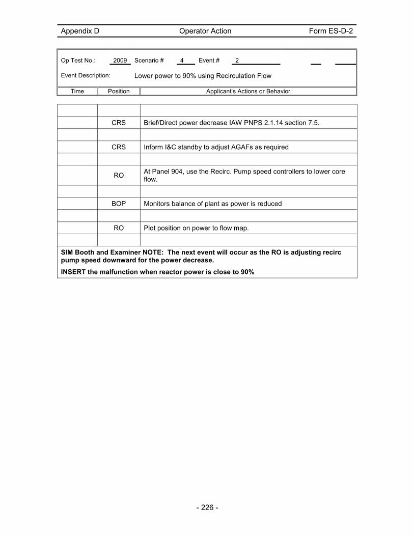
Appendix D Operator Action Form ES-D-2
Op Test No.: 2009 Scenario # 4 Event # 2 Event Description: Lower power to 90% using Recirculation Flow
Time Position Applicant’s Actions or Behavior
- 226 -
CRS Brief/Direct power decrease IAW PNPS 2.1.14 section 7.5.
CRS Inform I&C standby to adjust AGAFs as required
RO
At Panel 904, use the Recirc. Pump speed controllers to lower core flow.
BOP Monitors balance of plant as power is reduced
RO Plot position on power to flow map.
SIM Booth and Examiner NOTE: The next event will occur as the RO is adjusting recirc pump speed downward for the power decrease.
INSERT the malfunction when reactor power is close to 90%

Appendix D Operator Action Form ES-D-2
Op Test No.: 2009 Scenario # 4 Event # 3 Event Description: Recirc Flow Controller ‘A’ failure fails downscale.
Time Position Applicant’s Actions or Behavior
- 227 -
RO/BOP
Recognize/announce Recirc Pump ‘A’ Flow Controller failure.
Respond to Annunciator ANN 904RC-C7 MG ‘A’ Deviation High
Inform CRS of condition
CRS
Directs entry to PNPS 2.4.20, Reactor Recirculation System Speed or Flow Control System Malfunction.
RO Refers to PNPS 2.4.20.
CRS Direct initiating scoop lockup of ‘A’ Recirc pump.
RO Initiates ‘A’ Recirc pump scoop tube lockup.
CRS May refer to PNPS 2.4.19. – Scoop Tube Lockup
CRS Direct assessment of power to flow conditions.
RO Plot power and flow on power to flow map.
RO
Checks for loop flow balance IAW PNPS 2.2.84. (Within 10% above 80% power.)
CRS
Notify WWM to investigate and repair.
May contact system engineer
CRS
May Request licensed operator standby for manual operation of scoop tube positioned if needed.
CRS
Verify pump speeds within Tech Spec limits 3.6.F.1. - 24 hours to have loop flows within 10% at >80% power & 15% at<80% power

Appendix D Operator Action Form ES-D-2
Op Test No.: 2009 Scenario # 4 Event # 3 Event Description: Recirc Flow Controller ‘A’ failure fails downscale.
Time Position Applicant’s Actions or Behavior
- 228 -
When directed by Lead Examiner, proceed to next event
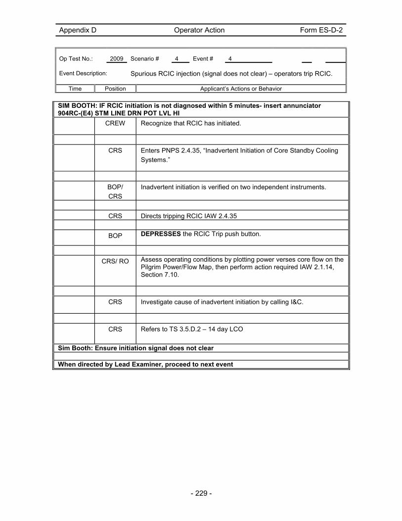
Appendix D Operator Action Form ES-D-2
Op Test No.: 2009 Scenario # 4 Event # 4 Event Description: Spurious RCIC injection (signal does not clear) – operators trip RCIC.
Time Position Applicant’s Actions or Behavior
- 229 -
SIM BOOTH: IF RCIC initiation is not diagnosed within 5 minutes- insert annunciator 904RC-(E4) STM LINE DRN POT LVL HI
CREW Recognize that RCIC has initiated.
CRS Enters PNPS 2.4.35, “Inadvertent Initiation of Core Standby Cooling
Systems.”
BOP/
CRS
Inadvertent initiation is verified on two independent instruments.
CRS Directs tripping RCIC IAW 2.4.35
BOP DEPRESSES the RCIC Trip push button.
CRS/ RO Assess operating conditions by plotting power verses core flow on the Pilgrim Power/Flow Map, then perform action required IAW 2.1.14, Section 7.10.
CRS Investigate cause of inadvertent initiation by calling I&C.
CRS Refers to TS 3.5.D.2 – 14 day LCO
Sim Booth: Ensure initiation signal does not clear When directed by Lead Examiner, proceed to next event
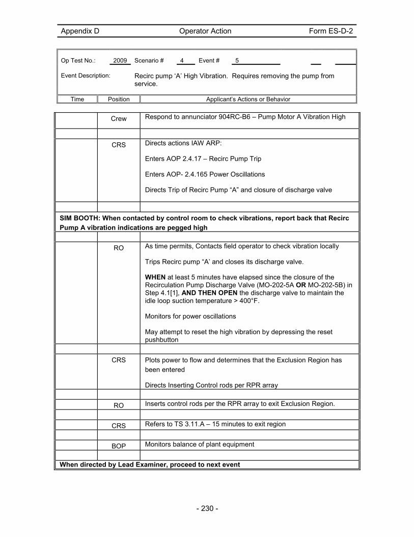
Appendix D Operator Action Form ES-D-2
Op Test No.: 2009 Scenario # 4 Event # 5 Event Description: Recirc pump ‘A’ High Vibration. Requires removing the pump from
service.
Time Position Applicant’s Actions or Behavior
- 230 -
Crew Respond to annunciator 904RC-B6 – Pump Motor A Vibration High
CRS Directs actions IAW ARP: Enters AOP 2.4.17 – Recirc Pump Trip Enters AOP- 2.4.165 Power Oscillations Directs Trip of Recirc Pump “A” and closure of discharge valve
SIM BOOTH: When contacted by control room to check vibrations, report back that Recirc
Pump A vibration indications are pegged high
RO As time permits, Contacts field operator to check vibration locally Trips Recirc pump “A’ and closes its discharge valve. WHEN at least 5 minutes have elapsed since the closure of the Recirculation Pump Discharge Valve (MO-202-5A OR MO-202-5B) in Step 4.1[1], AND THEN OPEN the discharge valve to maintain the idle loop suction temperature > 400°F. Monitors for power oscillations May attempt to reset the high vibration by depressing the reset pushbutton
CRS Plots power to flow and determines that the Exclusion Region has
been entered
Directs Inserting Control rods per RPR array
RO Inserts control rods per the RPR array to exit Exclusion Region.
CRS Refers to TS 3.11.A – 15 minutes to exit region
BOP Monitors balance of plant equipment
When directed by Lead Examiner, proceed to next event
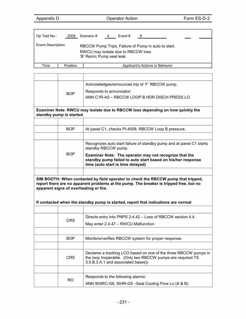
Appendix D Operator Action Form ES-D-2
Op Test No.: 2009 Scenario # 4 Event # 6 Event Description: RBCCW Pump Trips, Failure of Pump in auto to start.
RWCU may isolate due to RBCCW loss. ‘B’ Recirc Pump seal leak.
Time Position Applicant’s Actions or Behavior
- 231 -
BOP
Acknowledges/announces trip of ‘F’ RBCCW pump.
Responds to annunciator:
ANN C1R-A5 – RBCCW LOOP B HDR DISCH PRESS LO
Examiner Note: RWCU may isolate due to RBCCW loss depending on how quickly the standby pump is started.
BOP At panel C1, checks PI-4058, RBCCW Loop B pressure.
BOP
Recognizes auto start failure of standby pump and at panel C1 starts standby RBCCW pump.
Examiner Note: The operator may not recognize that the standby pump failed to auto start based on his/her response time (auto start is time delayed)
SIM BOOTH: When contacted by field operator to check the RBCCW pump that tripped, report there are no apparent problems at the pump. The breaker is tripped free, but no apparent signs of overheating or fire.
If contacted when the standby pump is started, report that indications are normal
CRS
Directs entry into PNPS 2.4.42 – Loss of RBCCW section 4.4.
May enter 2.4.47 – RWCU Malfunction
BOP Monitors/verifies RBCCW system for proper response.
CRS
Declares a tracking LCO based on one of the three RBCCW pumps in the loop Inoperable. (Only two RBCCW pumps are required TS 3.5.B.3.A.1 and associated bases))
RO
Responds to the following alarms:
ANN 904RC-G6, 904R-G5 –Seal Cooling Flow Lo (A & B)
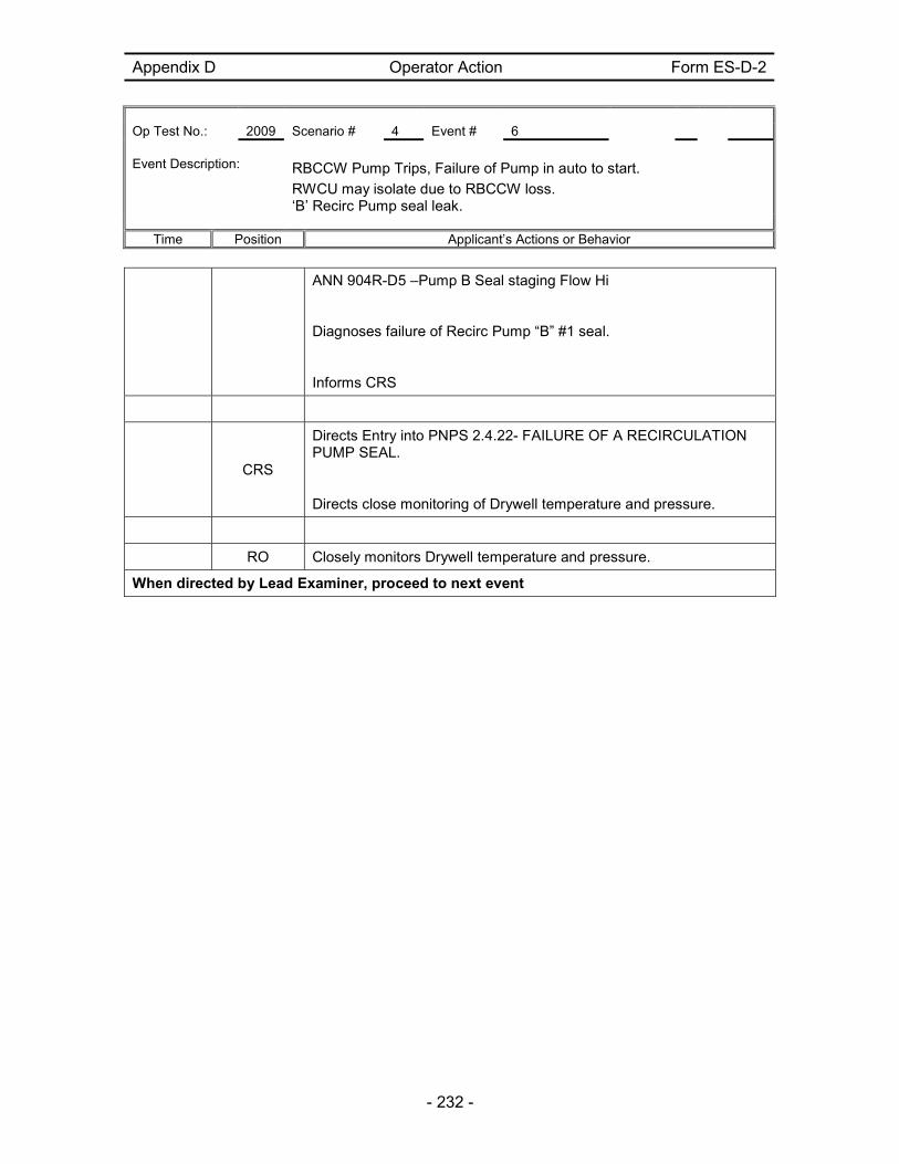
Appendix D Operator Action Form ES-D-2
Op Test No.: 2009 Scenario # 4 Event # 6 Event Description: RBCCW Pump Trips, Failure of Pump in auto to start.
RWCU may isolate due to RBCCW loss. ‘B’ Recirc Pump seal leak.
Time Position Applicant’s Actions or Behavior
- 232 -
ANN 904R-D5 –Pump B Seal staging Flow Hi
Diagnoses failure of Recirc Pump “B” #1 seal.
Informs CRS
CRS
Directs Entry into PNPS 2.4.22- FAILURE OF A RECIRCULATION PUMP SEAL.
Directs close monitoring of Drywell temperature and pressure.
RO Closely monitors Drywell temperature and pressure.
When directed by Lead Examiner, proceed to next event

Appendix C Page 233 of 235 Form ES-C-1
JPM CUE SHEET
- 233 -
Crew
Responds to the following annunciators:
ANN 904L-A6 – Steam leakage area temp high ANN 903-A1- CRD/Drywell Misc Temp Hi
CRS
Directs crew to read temperature of alarming module at Panel C921
Directs RO/BOP to send field operator to investigate area in alarm
Examiner Note: This malfunction is a pipe break in the RCIC steam supply line downstream of MO-1301-61. Area temperatures will rise requiring an EOP-04 entry then a reactor scram and entry to EOP-01. The leak will fail to isolate, (MO-1301-61, RCIC TURBINE SUPPLY ISOLATION VALVE and MO-1301-17, RCIC TURBINE SUPPLY OUTBD ISOL VALVE), eventually requiring an Emergency Depressurization IAW EOP-17.
SIM BOOTH: When contacted, report that there is steam in the room
CREW
Diagnoses based on alarm indication and field operator report that the leak is in the RCIC room.
CRS
Enters EOP-04 on High RCIC Normal Area Temperature
Directs operating available area coolers
Directs isolating RCIC
BOP
Recognizes RCIC failure to auto isolate on high temperature and attempts manual isolation
Reports to CRS that RCIC cannot be isolated
Critical Task
CRS
Determines that a reactor scram is required, in accordance with EOP-4, step SC-14 (which states: BEFORE any secondary containment parameter reaches its Maximum Safe Operating Value- Enter EOP-1). RCIC Area is approaching max safe temperature as stated in EOP-4 Table L.
Enters EOP-01.
Directs reactor scram
Critical Task
RO Places mode switch in shutdown

Appendix C Page 234 of 235 Form ES-C-1
JPM CUE SHEET
- 234 -
BOP/RO
Recognize failure of Main turbine to trip after reactor is scrammed
Manually trips the main turbine
RO Verify and announce the status of APRM downscales.
RO Verify all control rods are fully inserted.
RO
Insert IRM and SRM detectors, select two SRMs for recording, and place selector switch for APRM/IRM to “IRM”.
RO Verify reactor recirc pumps at minimum speed.
RO Verify trip of the turbine.
CRS
Direct reactor water level +20 - +40 inches using Feedwater/Condensate
CRS
Direct stabilizing pressure between 900-1050 psig with bypass valves.
BOP
As directed, Controls RPV pressure with bypass valves and RPV level with Feedwater /Condensate
CREW
Recognize and report when any area temperature exceeds Max Safe Value.
CRS
In anticipation of ED, may direct the reactor be rapidly depressurized to the main condenser via the Main Turbine Bypass Valves, disregarding the cooldown rate.
BOP
As directed rapidly depressurize the reactor to the main condenser via the Main Turbine Bypass Valves, disregarding the cooldown rate
CREW
Recognize and report when 2 or more area temperatures exceed Max Safe Value.
CRS
Directs Emergency Depressurization when 2 or more area temperatures exceed Max Safe Value.
First Area:
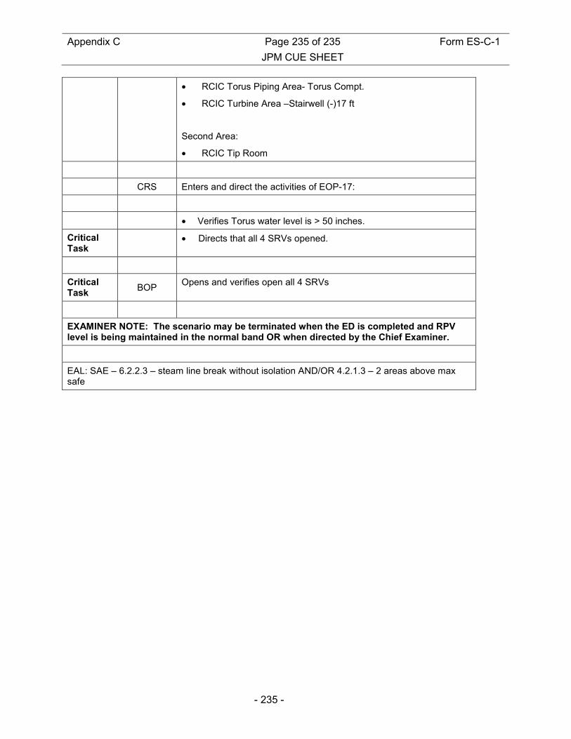
Appendix C Page 235 of 235 Form ES-C-1
JPM CUE SHEET
- 235 -
• RCIC Torus Piping Area- Torus Compt.
• RCIC Turbine Area –Stairwell (-)17 ft
Second Area:
• RCIC Tip Room
CRS Enters and direct the activities of EOP-17:
• Verifies Torus water level is > 50 inches.
Critical Task
• Directs that all 4 SRVs opened.
Critical Task
BOP Opens and verifies open all 4 SRVs
EXAMINER NOTE: The scenario may be terminated when the ED is completed and RPV level is being maintained in the normal band OR when directed by the Chief Examiner.
EAL: SAE – 6.2.2.3 – steam line break without isolation AND/OR 4.2.1.3 – 2 areas above max safe
![CALVERT C~LIFFS NUCLEAR POWER PLANT 2012 …NUCLEAR POWER PLANT 2012 NRC INITIAL LICENSED OPERA TOR ]~XAM JPM #: SRO-A~DMIN-1 Appendix C Job Perfonnance Measure Form ES-C-l Worksheet](https://img.pdfslide.net/doc/110x75/5e511c89e48cd419a20802fa/calvert-cliffs-nuclear-power-plant-2012-nuclear-power-plant-2012-nrc-initial-licensed.jpg)