Embed Size (px)
Citation preview

Copart, Inc.—Copart Palmdale Project Initial Study/Mitigated Negative Declaration
FirstCarbon Solutions Y:\Publications\Client (PN-JN)\5094\50940002\ISMND\50940002 Copart Palmdale ISMND.docx
Appendix D:Geotechnical Investigation Report

THIS PAGE INTENTIONALLY LEFT BLANK
Proposed Copart Palmdale Geotechnical Investigation Report
Prepared for: Copart Inc. 14185 Dallas Parkway, Suite 300 Dallas, Texas 75254
Prepared by: Stantec Consulting Services Inc. 735 East Carnegie Drive, Suite 280 San Bernardino, CA 92408
Project No. 2042546200
February 28, 2019

Stantec Consulting Services Inc. 735 East Carnegie Drive, Suite 280 San Bernardino, California 92408
February 28, 2019
Mr. Jeremy Meltebager Copart Inc. 14185 Dallas Parkway, Suite 300 Dallas, Texas 75254 RE: GEOTECHNICAL INVESTIGATION REPORT Proposed Copart Palmdale
Northwest Corner 40th Street East and Avenue L8 (Future) Palmdale, California 92054
Dear Mr. Meltebager:
This letter transmits Stantec’s geotechnical investigation report for the proposed Copart vehicle storage facility located in Palmdale, California. The purpose of this report is to evaluate the subsurface conditions and provide geotechnical recommendations for the proposed development.
We appreciate the opportunity to work with you on this project. If you have any questions, please call us at the numbers below.
Respectfully submitted,
STANTEC CONSULTING SERVICES INC.
Jaret Fischer, PE Evan Hsiao, PE, GE Principal Engineer Principal, Senior Geotechnical Engineer Phone: (909) 335-6116 ext. 8209 Phone: (949) 923-6963 [email protected] [email protected]

PROPOSED COPART PALMDALE GEOTECHNICAL INVESTIGATION REPORT
Table of Contents
1. INTRODUCTION ............................................................................................................. 1 1.1 PROPOSED DEVELOPMENT .............................................................................................. 1 1.2 PURPOSE AND SCOPE OF WORK .................................................................................... 1
1.2.1 Purpose ............................................................................................................ 1 1.2.2 Scope of Work ................................................................................................. 1
2. FIELD INVESTIGATION .................................................................................................... 2 2.1 PRE-DRILLING PROCEDURES ............................................................................................ 2 2.2 DRILLING OPERATIONS ..................................................................................................... 2 2.3 PERCOLATION TESTING ..................................................................................................... 2 2.4 SAMPLING .......................................................................................................................... 2
3. LABORATORY TESTING .................................................................................................. 4
4. GEOLOGIC SETTING AND SITE CONDITIONS ............................................................... 5 4.1 REGIONAL GEOLOGY ...................................................................................................... 5 4.2 SURFACE CONDITIONS ..................................................................................................... 5 4.3 SUBSURFACE CONDITIONS ............................................................................................... 5
5. GEOLOGIC HAZARDS ................................................................................................... 7 5.1 FAULTING AND SURFACE FAULT RUPTURE ...................................................................... 7 5.2 CALIFORNIA BUILDING CODE SEISMIC CRITERIA .......................................................... 7 5.3 LIQUEFACTION AND DYNAMIC SETTLEMENT .................................................................. 8 5.4 LIQUEFACTION INDUCED LATERAL SPREADING ............................................................ 8 5.5 FLOODING, TSUNAMIS AND SEICHES .............................................................................. 9 5.6 EXPANSIVE SOILS ............................................................................................................... 9
6. CONCLUSIONS ............................................................................................................ 10
7. RECOMMENDATIONS .................................................................................................. 11 7.1 EARTHWORK .................................................................................................................... 11
7.1.1 Site Preparation ............................................................................................ 11 7.1.2 Remedial Grading ........................................................................................ 11 7.1.3 Fill Placement and Compaction ................................................................ 12 7.1.4 Yielding Subgrade Conditions .................................................................... 12 7.1.5 Dewatering .................................................................................................... 13 7.1.6 Expansive Soil ................................................................................................ 13 7.1.7 Imported Material......................................................................................... 13 7.1.8 Site Excavation Characteristics .................................................................. 13 7.1.9 Oversized Material ........................................................................................ 13 7.1.10 Temporary Excavations ............................................................................... 13 7.1.11 Pipelines ......................................................................................................... 14 7.1.12 Surface Drainage ......................................................................................... 14 7.1.13 Grading Plan Review ................................................................................... 15
7.2 FOUNDATIONS ................................................................................................................. 15

PROPOSED COPART PALMDALE GEOTECHNICAL INVESTIGATION REPORT
7.2.1 Shallow Foundations .................................................................................... 15 7.2.2 Foundation Settlement ................................................................................ 15 7.2.3 Lateral Resistance ........................................................................................ 16 7.2.4 Foundation Plan Review .............................................................................. 16 7.2.5 Foundation Excavation Observations ....................................................... 16
7.3 SLABS-ON-GRADE ........................................................................................................... 16 7.3.1 Exterior Slabs on Grade (Sidewalks) ........................................................... 16
7.4 CORROSIVITY ................................................................................................................... 16 7.5 PAVEMENT ....................................................................................................................... 17 7.6 PERCOLATION TESTING ................................................................................................... 19 7.7 POST INVESTIGATION SERVICES ..................................................................................... 20
8. CLOSURE ...................................................................................................................... 21
9. REFERENCES ................................................................................................................. 22
LIST OF TABLES Table 1. Summary of Laboratory Tests ....................................................................................... 4 Table 2. Faults in Site Vicinity ....................................................................................................... 7 Table 3. 2016 CBC Seismic Parameters and Peak Ground Acceleration ............................ 7 Table 4. Flexible Pavement Sections ........................................................................................ 18 Table 5. Concrete Pavement Parameters .............................................................................. 18 Table 6. Recommended Concrete Pavement Sections ...................................................... 19
LIST OF FIGURES
Figure 1 - Site Location Map Figure 2 – Site Vicinity Map Figure 3 – Subsurface Exploration Map
LIST OF APPENDICES
BORING LOGS ........................................................................................... A.1
LABORATORY TEST RESULTS ....................................................................... B.1
PERCOLATION TEST RESULTS ..................................................................... C.1

PROPOSED COPART PALMDALE GEOTECHNICAL INVESTIGATION REPORT
Introduction February 28, 2019
fj v:\2042\active\2042546200\design\geotechncial\05_report_deliv\deliverable\reports\copart_palmdale_geotech_rpt_20190228.docx 1
1. INTRODUCTION
This report presents the results of Stantec’s geotechnical investigation for the proposed Copart facility in Palmdale, California. The project location is shown on the Site Location Map, Figure 1 and the approximate area of the proposed development is shown on the Site Vicinity Map, Figure 2.
1.1 PROPOSED DEVELOPMENT
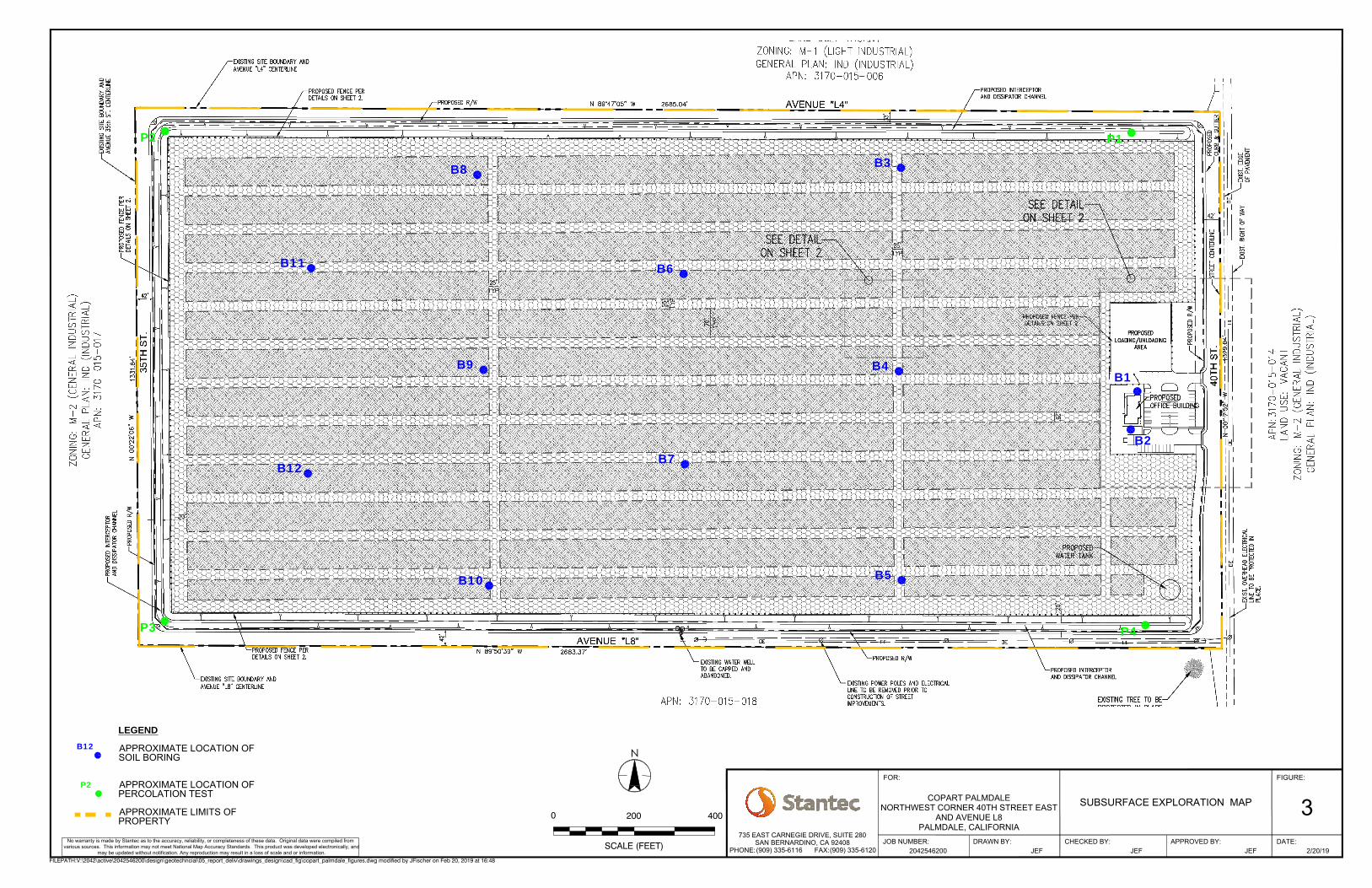
We understand the proposed Copart facility will include construction of a new 2,400 square feet (sf) building, approximately 67 acres of parking and drive isles, a perimeter infiltration trench, and landscape areas. The area of the proposed site improvements is shown on the Subsurface Exploration Map, Figure 3.
1.2 PURPOSE AND SCOPE OF WORK
1.2.1 Purpose
The purpose of this report is to evaluate the subsurface conditions at the site and provide geotechnical recommendations for design and construction of the proposed project. This report has been prepared in general accordance with accepted geotechnical engineering principles and in general conformance with the approved proposal.
1.2.2 Scope of Work
Our scope of work consisted of the following:
• Review available subsurface information for the site and nearby locations,
• Perform a site reconnaissance to evaluate general geotechnical and site conditions,
• Perform a field subsurface exploration program consisting of drilling 16 hollow stem auger borings, and converting four of the shallow borings into shallow percolation wells,
• Perform percolation testing,
• Perform geotechnical laboratory tests on selected samples,
• Perform geotechnical engineering analyses, and
• Preparation of this geotechnical investigation report for the proposed project.

PROPOSED COPART PALMDALE GEOTECHNICAL INVESTIGATION REPORT
Field Investigation February 28, 2019
fj v:\2042\active\2042546200\design\geotechncial\05_report_deliv\deliverable\reports\copart_palmdale_geotech_rpt_20190228.docx 2
2. FIELD INVESTIGATION
2.1 PRE-DRILLING PROCEDURES
DigAlert (Underground Service Alert of Southern California) was notified before commencing subsurface exploration activities to identify underground utilities that could conflict with the proposed borings. In addition, the upper five feet of soil was hand augered to clear the boring locations for potential conflicts with underground utilities.
2.2 DRILLING OPERATIONS
16 test borings (B-1 through B-12, P-1 through P-4) were drilled using a CME 85 drill rig equipped with hollow-stem augers on January 28, 2019 and January 29, 2019 by ABC Liovin Drilling (ABC). The borings were advanced to depths of approximately 6.5 feet to 51.5 feet below the existing ground surface (bgs), and their approximate locations are shown on the Subsurface Exploration Map, Figure 3. The borings were logged by a Stantec field geologist, who also collected samples of the materials encountered for examination and laboratory testing.
2.3 PERCOLATION TESTING
Four of the borings were converted to shallow percolation wells (P-1 through P-4) and percolation testing was performed in the wells by a Stantec field geologist on January 29, 2019 in general accordance with Los Angeles County percolation testing guidelines.
2.4 SAMPLING
Relatively undisturbed samples were obtained using a modified California (CAL) sampler, which is a ring-lined split tube sampler with a 3-inch outer diameter and 2½-inch inner diameter. CAL sampling followed ASTM D3550 (Standard Practice for Ring-Lined Barrel Sampling of Soils) procedures. Disturbed samples were obtained using a Standard Penetration Test (SPT) sampler, which is a split tube sampler with a 2-inch outer diameter and 1⅜-inch inner diameter. SPTs were performed in general accordance with ASTM D1586 (Standard Test Method for Penetration Test and Split-Barrel Sampling of Soils), and D6066 (Standard Practice for Determining the Normalized Penetration Resistance of Sands for Evaluation of Liquefaction Potential). Disturbed bulk samples were also obtained from the drill cuttings.
The CAL and SPT samplers were driven with a 140-pound weight dropping 30 inches. The number of blows per 6-inch increment is noted on the boring logs. ABC provided a report (Earthspectives, 2018) which indicates the average hammer energy efficiency on the drill rig used at the project was 80%.

PROPOSED COPART PALMDALE GEOTECHNICAL INVESTIGATION REPORT
Field Investigation February 28, 2019
fj v:\2042\active\2042546200\design\geotechncial\05_report_deliv\deliverable\reports\copart_palmdale_geotech_rpt_20190228.docx 3
Samples were classified in the field using the Unified Soil Classification System (USCS), in accordance with ASTM D2488 (Standard Practice for Description and Identification of Soils [Visual-Manual Method]) procedures. The laboratory testing confirmed or modified field classifications as necessary for presentation on the boring logs. Soil samples were removed from the samplers, placed in appropriate containers, and transported in accordance with ASTM D4220 (Standard Practice for Preserving and Transporting Soil Samples). Upon completion, borings were backfilled with grout and capped with concrete in the upper three feet. The boring logs are included in Appendix A.

PROPOSED COPART PALMDALE GEOTECHNICAL INVESTIGATION REPORT
Laboratory Testing February 28, 2019
fj v:\2042\active\2042546200\design\geotechncial\05_report_deliv\deliverable\reports\copart_palmdale_geotech_rpt_20190228.docx 4
3. LABORATORY TESTING
The following laboratory tests were performed in general accordance with ASTM and California Test procedures:
Table 1. Summary of Laboratory Tests
Type of Test ASTM Designation Number Performed
In-Situ Moisture and Density ASTM D-2216 14
Sieve Analysis ASTM D422 and ASTM C136 18
Direct Shear ASTM D3080 2
Resistance (R)-Value Analysis ASTM D2844, California 301G 1
Maximum Dry Density and Optimum Moisture Content ASTM D1557 2
Chemical Tests for Corrosion Potential CA DOT test methods 1
The laboratory test results are presented in Appendix B.

PROPOSED COPART PALMDALE GEOTECHNICAL INVESTIGATION REPORT
Geologic Setting and Site Conditions February 28, 2019
fj v:\2042\active\2042546200\design\geotechncial\05_report_deliv\deliverable\reports\copart_palmdale_geotech_rpt_20190228.docx 5
4. GEOLOGIC SETTING AND SITE CONDITIONS
4.1 REGIONAL GEOLOGY
The site is located in the Mohave Desert geologic province which consists of a broad interior region of isolated mountains separated by desert plains with an enclosed drainage system. The Mojave Desert Geomorphic Province is wedged in a sharp angle between the San Andreas and Garlock faults (CGS, 2008). The Site resides in the portion of the Province drained by surface runoff toward Little Rock Wash, which drains into Rosamond Lake.
Geologic mapping presented in the United States Geological Survey (USGS) Lancaster Quadrangle (USGS, 2005) indicates the site is underlain by recent alluvial deposits. Literature from the USGS indicates the Quaternary alluvial deposits consist of gravel, sand, and silt.
4.2 SURFACE CONDITIONS
The project site is approximately 82 acres in size and is occupied by vacant former agricultural land. The project site is bound by 40th Street East followed by agricultural land to the east, Avenue L8 (future) followed by vacant land and agricultural land to the south, 35th Street East followed by vacant land to the west, and Avenue L4 (Future) followed by former agricultural and vacant land to the north.
The site is generally flat and slopes from southeast to northwest. Based on Google Earth®, the ground surface of the site is at an approximate elevation of 2,457 to 2,466 feet (WGS84 Datum).
4.3 SUBSURFACE CONDITIONS
The materials encountered in our borings consist of Quaternary Alluvial (Qa) deposits. A brief description of the subsurface conditions is provided in this section. Detailed descriptions of the subsurface conditions are provided in the boring logs included in Appendix A.
Quaternary Alluvial Deposits (Qa) – Quaternary Alluvial deposits were encountered in all borings and extends to depths of at least 51.5 feet bgs. The alluvial deposits encountered at this location primarily consist of sand with variable amounts of clay and silt (SW, SP-SM, SW-SM, SM, and SC USCS soil type) and sandy silt (ML USCS soil type). The sandy deposits encountered were loose to medium dense and generally dry with increasing density below 30 feet. The fine-grained deposits were moist.
Groundwater - Groundwater was not encountered during this investigation. Groundwater monitoring data at the Palmdale Water Reclamation Plan approximately one mile southeast of the site indicates groundwater was encountered at a depth of approximately 411 feet below the

PROPOSED COPART PALMDALE GEOTECHNICAL INVESTIGATION REPORT
Geologic Setting and Site Conditions February 28, 2019
fj v:\2042\active\2042546200\design\geotechncial\05_report_deliv\deliverable\reports\copart_palmdale_geotech_rpt_20190228.docx 6
ground surface (LACSD, 2018). The offsite location is approximately 16 feet higher in elevation than the proposed Copart site. Groundwater levels may fluctuate seasonally, or in the future due to rainfall, irrigation, broken pipes, or changes in site drainage.

PROPOSED COPART PALMDALE GEOTECHNICAL INVESTIGATION REPORT
Geologic Hazards February 28, 2019
fj v:\2042\active\2042546200\design\geotechncial\05_report_deliv\deliverable\reports\copart_palmdale_geotech_rpt_20190228.docx 7
5. GEOLOGIC HAZARDS
5.1 FAULTING AND SURFACE FAULT RUPTURE
The site is located in a seismically active area. The estimated closest distance from the site to major nearby mapped active faults is presented in the table below.
Table 2. Faults in Site Vicinity
Fault Distance (miles) (1)
Maximum Moment Magnitude (1)
San Andreas 7.7 8.2 San Gabriel 26.1 7.3 Sierra Madre 29.1 7.3 Northridge 29.8 6.9
Clamshell-Sawpit 31.1 6.7 1Measured from 2008 National Seismic Hazard Maps – Source Parameters Website - USGS (USGS, 2008).
As noted above, the closest known active fault is the San Andreas Fault, located approximately 7.7 miles southwest of the site. No active faults are known to underlie or project toward the site. Therefore, the probability of surface fault rupture at the site from a known active fault is considered low.
5.2 CALIFORNIA BUILDING CODE SEISMIC CRITERIA
A geologic hazard likely to affect the project is ground-shaking as a result of movement along an active fault zone in the vicinity of the subject site. The seismic parameters in accordance with the 2016 California Building Code (CBC) are presented below:
Table 3. 2016 CBC Seismic Parameters and Peak Ground Acceleration
Parameter Value
Site Coordinates Latitude : 34.654542° Longitude : -118.063119°
Mapped Spectral Acceleration Value at Short Period: Ss 1.5g Mapped Spectral Acceleration Value at 1-Second Period: S1 0.632g Seismic Site Classification D Short Period Site Coefficient: Fa 1.0 1-Second Period Site Coefficient: Fv 1.5 Site Class Adjusted Acceleration Value at Short Period: SMS 1.5g Site Class Adjusted Acceleration Value at 1-Second Period: SM1 0.949g Design Spectral Response Acceleration at Short Periods: SDS 1.0g Design Spectral Response Acceleration at 1-Second Period: SD1 0.632g Peak Ground Acceleration adjusted for Site Class Effects: PGAM 0.552g
ASCE 7-10 – Report generated through ASCE 7 Hazards Report website (ASCE, 2019) – accessed 2/22/19.

PROPOSED COPART PALMDALE GEOTECHNICAL INVESTIGATION REPORT
Geologic Hazards February 28, 2019
fj v:\2042\active\2042546200\design\geotechncial\05_report_deliv\deliverable\reports\copart_palmdale_geotech_rpt_20190228.docx 8
5.3 LIQUEFACTION AND DYNAMIC SETTLEMENT
Liquefaction is the transformation of a deposit of soil from a solid state to a liquefied state as a consequence of increased pore pressure and reduced effective stress. Often, this transformation results from the cyclic loading of an earthquake and the soil acquires “mobility” sufficient to permit both horizontal and vertical movements. Soils that are most susceptible to liquefaction are clean, loose, saturated (below groundwater), and uniformly graded sands. The vast majority of liquefaction hazards are associated with sandy soils in looser state and silty soils of low plasticity. Cohesive soils are generally not considered susceptible to soil liquefaction, although they can be subject to cyclic softening if they are soft enough, and if the seismic demand is relatively high.
The site is not located in a California Geological Survey Liquefaction Hazard Zone. This zone is defined as areas where historical occurrence of liquefaction, or local geological, geotechnical and groundwater conditions indicate a potential for permanent ground displacements such that mitigation would be required.
The liquefaction potential was evaluated with the LiqSVs v1.1.1.12 computer program (Geologismiki, 2017) using the SPT data from soil boring B1. Liquefaction triggering methods developed by Idriss and Boulanger (2014) were used in our liquefaction evaluation. Our evaluation was based on the site class adjusted peak ground acceleration (PGAM) of 0.552g, as presented in Table 2, and an earthquake magnitude of 7.9 which is the modal earthquake magnitude from the 2008 USGS deaggregation website. The groundwater depth of 411 feet (LACSD, 2018) was used to evaluate the cyclic stress ratio for the design earthquake, and the estimated insitu groundwater depth of 411 feet was used to evaluate the cyclic resistance ratio for the on-site soils.
Loose to dense granular soil is generally present from the ground surface to a depth of at least 51.5 feet at the site. Based on the density and location of groundwater table, most of this granular soil in the top 50 feet is generally not susceptible to seismically induced settlement. However, some of the unsaturated, loose to medium dense sand in the upper 50 feet may densify as a result of earthquake shaking, causing ground surface settlement. Ground surface total settlements due to compression in the unsaturated zone are estimated to be on the order of ¾ inch. Differential settlement over a span of approximately 30 feet is estimated to be approximately 0.4 inch.
5.4 LIQUEFACTION INDUCED LATERAL SPREADING
Liquefaction induced lateral spreading can occur in areas of sloping ground, or towards a free face. Given the depth to groundwater, and since the topography at the site is relatively flat, the potential for liquefaction induced lateral spreading is considered low.

PROPOSED COPART PALMDALE GEOTECHNICAL INVESTIGATION REPORT
Geologic Hazards February 28, 2019
fj v:\2042\active\2042546200\design\geotechncial\05_report_deliv\deliverable\reports\copart_palmdale_geotech_rpt_20190228.docx 9
5.5 FLOODING, TSUNAMIS AND SEICHES
The site is not located within a FEMA flood zone, therefore, damage due to flooding is considered low.
The site is not located within a Tsunami Inundation Area; therefore, damage due to tsunamis is considered low.
5.6 EXPANSIVE SOILS
The near-surface soils (upper approximate 10 feet) have a low expansion potential. Our soil classifications and laboratory test results show that the near surface (upper 10 feet) samples tested are granular with low-plasticity fines. Accordingly, mitigation for expansive soils is not considered necessary for onsite soils at this site.
If imported soils are used for earthwork, Stantec recommends that the proposed soils be tested for expansion potential prior to import. Imported soils should be approved by the Geotechnical Engineer before being imported.

PROPOSED COPART PALMDALE GEOTECHNICAL INVESTIGATION REPORT
Conclusions February 28, 2019
fj v:\2042\active\2042546200\design\geotechncial\05_report_deliv\deliverable\reports\copart_palmdale_geotech_rpt_20190228.docx 10
6. CONCLUSIONS
Based on our field exploration, laboratory testing and engineering and geologic analyses, it is our opinion that the subject property is suitable for construction of the proposed vehicle storage facility improvements from a geotechnical engineering and engineering geology viewpoint; however, there are existing geotechnical conditions associated with the site that warrant mitigation and/or consideration during the planning stages. The main geotechnical conclusions for the project are presented in the following paragraphs.
• The site is underlain by Quaternary Alluvial deposits from the ground surface in all soil borings and extends to depths of at least 51.5 feet bgs. The alluvial deposits encountered at this location primarily consist of sand with variable amounts of clay and silt (SW, SP-SM, SW-SM, SM, and SC USCS soil type) and sandy silt (ML USCS soil type). The sandy deposits encountered were loose to medium dense and generally dry with increasing density below 30 feet. The fine-grained deposits were moist.
• Groundwater was not encountered during this investigation. Groundwater monitoring data at the Palmdale Water Reclamation Plan approximately one mile southeast of the site indicates groundwater was encountered at a depth of approximately 411 feet below the ground surface (LACSD, 2018). The offsite location is approximately 16 feet higher in elevation than the proposed Copart site. Groundwater levels may fluctuate seasonally, or in the future due to rainfall, irrigation, broken pipes, or changes in site drainage.
• Loose to dense alluvial deposits primarily consisting of granular soil is generally present from the ground surface to a depth of at least 51.5 feet at the site. Based on the depth of the groundwater table and soil density, most of this granular soil in the top 50 feet is generally not susceptible to seismically induced settlement. However, some of the unsaturated, loose to medium dense sand in the upper 50 feet may densify as a result of earthquake shaking, causing ground surface settlement. Ground surface total settlements due to compression in the unsaturated zone are estimated to be on the order of 0.8 inches. Differential settlement over a span of approximately 30 feet is estimated to be approximately 0.4 inches.
• Based on the relatively low estimated liquefaction induced settlement, conventional shallow foundations appear to be a suitable option for support of the proposed building.
• No active faults are known to underlie or project toward the site. Therefore, the probability of surface fault rupture occurring at the site from a known active fault is considered low.

PROPOSED COPART PALMDALE GEOTECHNICAL INVESTIGATION REPORT
Recommendations February 28, 2019
fj v:\2042\active\2042546200\design\geotechncial\05_report_deliv\deliverable\reports\copart_palmdale_geotech_rpt_20190228.docx 11
7. RECOMMENDATIONS
7.1 EARTHWORK
The following recommendations are provided regarding specific aspects of the proposed earthwork construction. These recommendations should be considered subject to revision based on additional geotechnical evaluation of the conditions observed by the Geotechnical Engineer during grading operations.
7.1.1 Site Preparation
Site preparation should begin with the removal of existing buried slabs and foundations, vegetation, highly organic soil, leach lines, septic tanks, and any other unsuitable materials, as applicable. Existing underground utilities within the proposed construction areas should be completely removed and/or rerouted. Grading should conform to the guidelines presented in the 2016 California Building Code (CBC, 2016), as well as the pertinent requirements of the City of Palmdale and Los Angeles County.
7.1.2 Remedial Grading
Building Foundation Areas:
To provide uniform support for the proposed building, removal of the existing soils to a minimum depth of 2 feet below the bottom of the footings is recommended. Removal, replacement, and compaction should be completed laterally at least five feet beyond the outside edge of the footings unless constrained by existing structures. The bottom of the over excavation should be scarified to a depth of 8-inches, moisture conditioned to within 2 percentage points of the optimum moisture content and compacted to at least 90% relative compaction based on the ASTM D1557 laboratory test procedure. All references to optimum moisture content and relative compaction in this report are based on this test method.
Concrete Pavement and Hardscape:
Remedial grading for pavement and hardscape areas should include removal of the existing soils to a depth of at least 12 inches below the existing ground surface or subgrade elevation, whichever is deeper. Subgrade elevation is defined as the top of soil elevation provided in the grading plan. The soil exposed at the base of the excavation should be scarified to a depth of 8 inches, and moisture conditioned to within 2 percentage points of the optimum moisture content. Hardscape subgrade should be compacted to at least 90% relative compaction. Pavement subgrade should be compacted to at least 90% relative compaction.

PROPOSED COPART PALMDALE GEOTECHNICAL INVESTIGATION REPORT
Recommendations February 28, 2019
fj v:\2042\active\2042546200\design\geotechncial\05_report_deliv\deliverable\reports\copart_palmdale_geotech_rpt_20190228.docx 12
Field Observations:
The Geotechnical Engineer should check the bottom of excavations. If soft, loose, or otherwise unsuitable soils are encountered, the depth of removal may need to be extended.
7.1.3 Fill Placement and Compaction
Excavated materials determined by the Geotechnical Engineer to be satisfactory can be reused as compacted fill. We anticipate that the majority of the excavated materials can be re-used as compacted fill soils. The Geotechnical Engineer should approve the fill material before placement.
Where large compaction equipment, such as sheep’s foot or smooth drum compactors, are used, fill should be placed in 6- to 8-inch thick loose, horizontal lifts, moisture conditioned to within 2 percentage points of the optimum moisture content and compacted to at least 90% relative compaction. Thinner lifts will be required for smaller compaction equipment. The maximum dry density and optimum moisture content for the evaluation of relative compaction should be determined in accordance with ASTM D1557.
7.1.4 Yielding Subgrade Conditions
The soil encountered at the bottom of the remedial grading excavations can exhibit “pumping” or yielding if they become saturated in response to periods of significant precipitation, such as during the winter rainy season. If this occurs, corrective measures should be performed with oversight from the Geotechnical Engineer.
In order to help stabilize the yielding subgrade soils within the bottom of the removal areas, the contractor can consider the placement of stabilization fabric or geo-grid over the yielding areas, depending on the relative severity of the yielding.
Mirafi 600X (or approved equivalent) stabilization fabric may be used for areas with low to moderate yielding conditions. Geo-grid such as Tensar TX-5 may be used for areas with moderate to severe yielding conditions. Uniform sized, ¾- to 2-inch crushed rock should be placed over the stabilization fabric or geo-grid. A 6- to 12-inch thick section of crushed rock will typically be necessary to stabilize yielding ground.
If significant voids are present in the crushed gravel, a filter fabric should be placed over the crushed gravel to prevent migration of fines into the gravel and thus potential settlement of the overlying fill. Fill soils, which should be placed and compacted in accordance with the recommendations presented herein, should then be placed over the fabric or geo-grid until design grades are reached. The crushed gravel and stabilization fabric or geo-grid should extend at least 5 feet laterally beyond the limits of the yielding areas.
PROPOSED COPART PALMDALE GEOTECHNICAL INVESTIGATION REPORT
Recommendations February 28, 2019
fj v:\2042\active\2042546200\design\geotechncial\05_report_deliv\deliverable\reports\copart_palmdale_geotech_rpt_20190228.docx 13
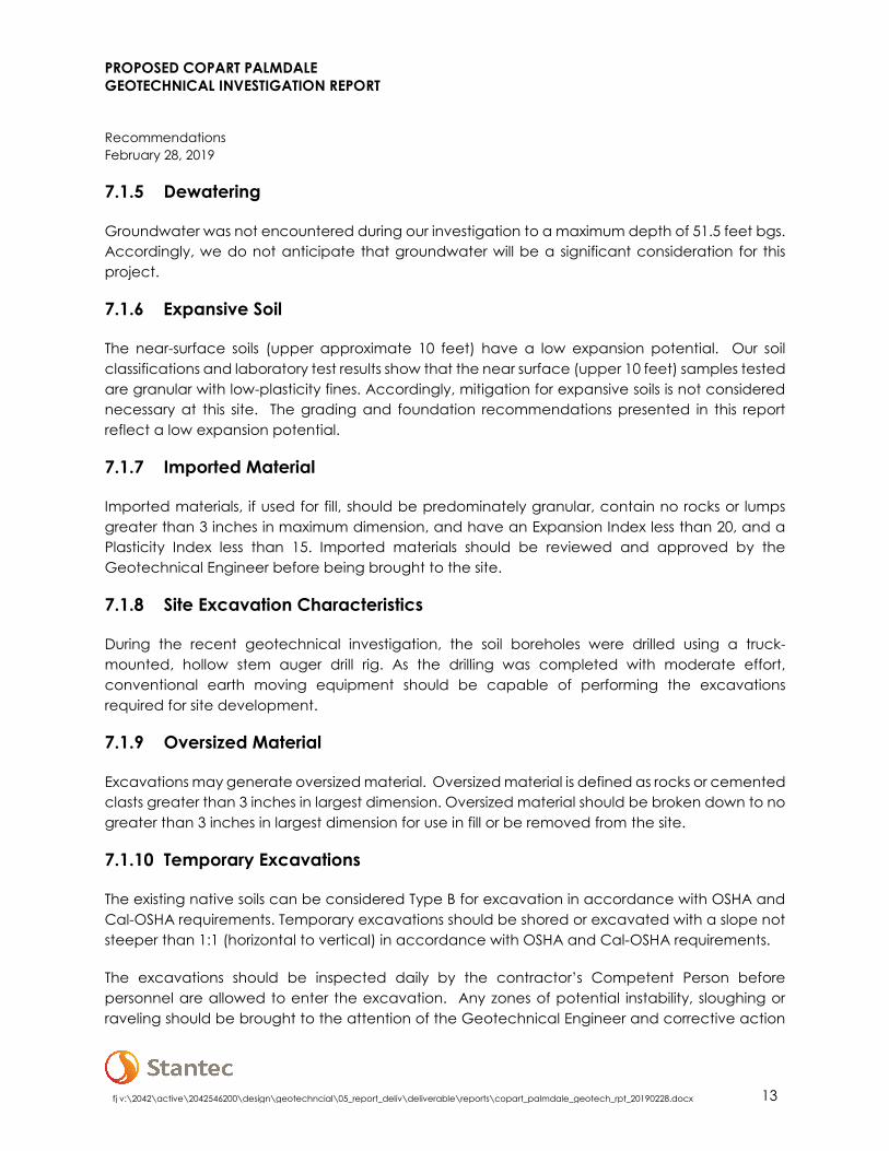
7.1.5 Dewatering
Groundwater was not encountered during our investigation to a maximum depth of 51.5 feet bgs. Accordingly, we do not anticipate that groundwater will be a significant consideration for this project.
7.1.6 Expansive Soil
The near-surface soils (upper approximate 10 feet) have a low expansion potential. Our soil classifications and laboratory test results show that the near surface (upper 10 feet) samples tested are granular with low-plasticity fines. Accordingly, mitigation for expansive soils is not considered necessary at this site. The grading and foundation recommendations presented in this report reflect a low expansion potential.
7.1.7 Imported Material
Imported materials, if used for fill, should be predominately granular, contain no rocks or lumps greater than 3 inches in maximum dimension, and have an Expansion Index less than 20, and a Plasticity Index less than 15. Imported materials should be reviewed and approved by the Geotechnical Engineer before being brought to the site.
7.1.8 Site Excavation Characteristics
During the recent geotechnical investigation, the soil boreholes were drilled using a truck-mounted, hollow stem auger drill rig. As the drilling was completed with moderate effort, conventional earth moving equipment should be capable of performing the excavations required for site development.
7.1.9 Oversized Material
Excavations may generate oversized material. Oversized material is defined as rocks or cemented clasts greater than 3 inches in largest dimension. Oversized material should be broken down to no greater than 3 inches in largest dimension for use in fill or be removed from the site.
7.1.10 Temporary Excavations
The existing native soils can be considered Type B for excavation in accordance with OSHA and Cal-OSHA requirements. Temporary excavations should be shored or excavated with a slope not steeper than 1:1 (horizontal to vertical) in accordance with OSHA and Cal-OSHA requirements.
The excavations should be inspected daily by the contractor’s Competent Person before personnel are allowed to enter the excavation. Any zones of potential instability, sloughing or raveling should be brought to the attention of the Geotechnical Engineer and corrective action

PROPOSED COPART PALMDALE GEOTECHNICAL INVESTIGATION REPORT
Recommendations February 28, 2019
fj v:\2042\active\2042546200\design\geotechncial\05_report_deliv\deliverable\reports\copart_palmdale_geotech_rpt_20190228.docx 14
implemented before personnel begin working in the excavation. Excavated soils should not be stockpiled behind temporary excavations within a distance equal to the depth of the excavation.
The project geotechnical engineer should be notified if other surcharge loads are anticipated so that lateral load criteria can be developed for the specific situation. If temporary slopes are to be maintained during the rainy season, berms are recommended near the tops of slopes to prevent runoff water from entering the excavation and eroding the slope faces.
7.1.11 Pipelines
Typical pipe bedding as specified in the Standard Specifications for Public Works Construction (GREENBOOK) may be used. As a minimum, it is recommended that pipe be supported on at least 4 inches of granular bedding material, such as 3/4-inch rock or clean coarse sand with less than 5 percent fines and a sand equivalent of 40 or more as evaluated by ASTM D2419.
The bedding should extend from the bottom of the trench to at least 1 foot above the top of the pipe. Sand bedding should be mechanically compacted to at least 90 percent relative compaction. Jetting of sand bedding should not be permitted.
Onsite material, imported select material, or 2-sack cement/sand slurry may be used as backfill in trenches above the pipe bedding. The material selected should match the engineering characteristics of the soils adjacent to the trench. Utility trench backfill beneath structures and hardscape should be compacted to at least 90% relative compaction.
The modulus of soil reaction (E’) is used to characterize the stiffness of soil backfill placed along the sides of buried flexible pipelines. For the purpose of evaluating deflection due to the load associated with trench backfill over the pipe, a value of 1,500 pounds per square inch (lbs/in2) is recommended for the general site conditions assuming granular bedding material (sand or gravel) is placed around the pipe.
7.1.12 Surface Drainage
Final surface grades around structures should be designed to collect and direct surface water away from the structure and toward appropriate drainage facilities. The ground around the structure should be graded so that surface water flows rapidly away from the structure without ponding. In general, we recommend that the ground adjacent to the structure slope away at a gradient of at least 2%. Densely vegetated areas where runoff can be impaired should have a minimum gradient of at least 5% within the first 5 feet from the structure. Roof gutters with downspouts that discharge directly into a closed drainage system are recommended on structures. Drainage patterns established at the time of fine grading should be maintained throughout the life of the proposed structures. Site irrigation should be limited to the minimum necessary to sustain landscape growth. Should excessive irrigation, impaired drainage, or

PROPOSED COPART PALMDALE GEOTECHNICAL INVESTIGATION REPORT
Recommendations February 28, 2019
fj v:\2042\active\2042546200\design\geotechncial\05_report_deliv\deliverable\reports\copart_palmdale_geotech_rpt_20190228.docx 15
unusually high rainfall occur, saturated zones of perched groundwater can develop. Saturated soil zones may result in increased maintenance and could impact structure stability.
7.1.13 Grading Plan Review
Stantec should review the grading plans and earthwork specifications to ascertain whether the intent of the recommendations contained in this report have been implemented, and that no revised recommendations are needed due to changes in the development scheme.
7.2 FOUNDATIONS
7.2.1 Shallow Foundations
Conventional shallow foundations (spread footings/strip footings) are considered suitable for support of the proposed building provided the recommendations in this report are incorporated into the design.
The following foundation recommendations are minimum criteria based on geotechnical considerations. They should not be considered a structural design, nor should they be considered to preclude more restrictive criteria by governing agencies or the structural engineer. The design of the foundation system should be performed by the project structural engineer.
Conventional Shallow Foundations:
An allowable bearing pressure of 2,500 pounds per square foot (psf) may be used for conventional square or rectangular shallow foundations founded in properly compacted fill prepared in accordance with the recommendations of this report. The bearing capacity can be increased by one third for transient loading conditions such as earthquake and wind.
Additional parameters for shallow foundations are provided below.
Minimum Footing Width: 18 inches for continuous footings 24 inches for square/rectangular footings
Minimum Footing Depth: 18 inches below lowest adjacent soil grade
Minimum Reinforcement: Two No. 5 bars at both top and bottom in continuous footings.
7.2.2 Foundation Settlement
The following static and seismic foundation settlements are estimated.
Static Settlement: Less than 1-inch total settlement
PROPOSED COPART PALMDALE GEOTECHNICAL INVESTIGATION REPORT
Recommendations February 28, 2019
fj v:\2042\active\2042546200\design\geotechncial\05_report_deliv\deliverable\reports\copart_palmdale_geotech_rpt_20190228.docx 16
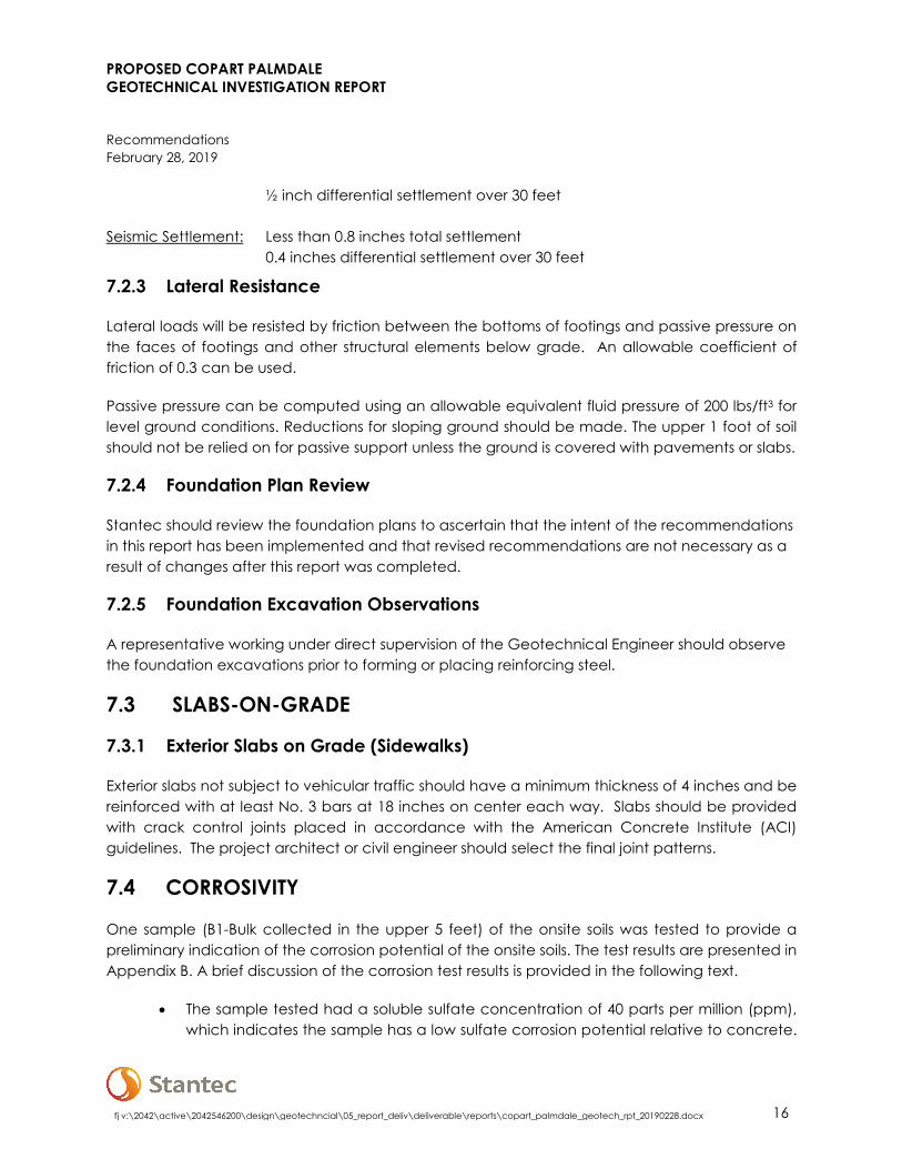
½ inch differential settlement over 30 feet
Seismic Settlement: Less than 0.8 inches total settlement 0.4 inches differential settlement over 30 feet
7.2.3 Lateral Resistance
Lateral loads will be resisted by friction between the bottoms of footings and passive pressure on the faces of footings and other structural elements below grade. An allowable coefficient of friction of 0.3 can be used.
Passive pressure can be computed using an allowable equivalent fluid pressure of 200 lbs/ft3 for level ground conditions. Reductions for sloping ground should be made. The upper 1 foot of soil should not be relied on for passive support unless the ground is covered with pavements or slabs.
7.2.4 Foundation Plan Review
Stantec should review the foundation plans to ascertain that the intent of the recommendations in this report has been implemented and that revised recommendations are not necessary as a result of changes after this report was completed.
7.2.5 Foundation Excavation Observations
A representative working under direct supervision of the Geotechnical Engineer should observe the foundation excavations prior to forming or placing reinforcing steel.
7.3 SLABS-ON-GRADE
7.3.1 Exterior Slabs on Grade (Sidewalks)
Exterior slabs not subject to vehicular traffic should have a minimum thickness of 4 inches and be reinforced with at least No. 3 bars at 18 inches on center each way. Slabs should be provided with crack control joints placed in accordance with the American Concrete Institute (ACI) guidelines. The project architect or civil engineer should select the final joint patterns.
7.4 CORROSIVITY
One sample (B1-Bulk collected in the upper 5 feet) of the onsite soils was tested to provide a preliminary indication of the corrosion potential of the onsite soils. The test results are presented in Appendix B. A brief discussion of the corrosion test results is provided in the following text.
• The sample tested had a soluble sulfate concentration of 40 parts per million (ppm), which indicates the sample has a low sulfate corrosion potential relative to concrete.

PROPOSED COPART PALMDALE GEOTECHNICAL INVESTIGATION REPORT
Recommendations February 28, 2019
fj v:\2042\active\2042546200\design\geotechncial\05_report_deliv\deliverable\reports\copart_palmdale_geotech_rpt_20190228.docx 17
It should be noted that soluble sulfate in the irrigation water supply, and/or the use of fertilizer may cause the sulfate content in the surficial soils to increase with time. This may result in a higher sulfate exposure than that indicated by the test results reported herein. Studies have shown that the use of improved cements in the concrete, and a low water-cement ratio will improve the resistance of the concrete to sulfate exposure.
• The sample tested had a chloride concentration of 99 ppm, which indicates the sample has a negligible chloride corrosion potential relative to metal.
• The sample tested had a minimum resistivity of 4,853 ohm-cm, which indicates the sample is moderately corrosive.
• The sample tested had a pH of 7.2 which indicates the sample is slightly alkaline.
Caltrans currently considers a site to be corrosive to foundation elements if one or more of the following conditions exist: Chloride concentration is greater than or equal to 500 ppm, sulfate concentration is greater than or equal to 1,500 ppm, or the pH is 5.5 or less (Caltrans, 2012).
Based on Caltrans criteria, the test results indicate the site is not considered to be a corrosive environment for structures. However, other samples at the site could yield significantly different concentrations to those described above. Therefore, additional testing may be performed to further evaluate corrosion during the planning or construction stages and to evaluate the as-graded corrosion potential of the onsite soils after site grading. We recommend evaluation by a corrosion engineer should be performed.
7.5 PAVEMENT
7.5.1 Asphalt Concrete Pavement
An R-Value of 20 has been assumed for preliminary design of pavement sections based on laboratory test results and visual observation of the on-site material in the upper 5 feet. The actual R-value of the subgrade soils should be determined after grading to provide final pavement design. Flexible pavement sections have been calculated in general conformance with Caltrans guidelines. Site development plans call for the Site to be used as a vehicle storage lot. In consideration of the property use, the owner has asked for different pavement options and levels of maintenance. The project engineer, in consultation with the owner, may select a pavement design with the understanding that they represent different levels of maintenance. The project civil engineer and owner should review the pavement designations to determine appropriate locations for pavement thickness. Based on an assumed R-value of 20, the following pavement structural sections have been calculated and presented in Table 4.

PROPOSED COPART PALMDALE GEOTECHNICAL INVESTIGATION REPORT
Recommendations February 28, 2019
fj v:\2042\active\2042546200\design\geotechncial\05_report_deliv\deliverable\reports\copart_palmdale_geotech_rpt_20190228.docx 18
Table 4. Flexible Pavement Sections
Traffic Type Traffic Index
Asphalt Concrete (inches)
Aggregate Base (2) (inches)
Chip Seal (inches)
Cement Treated Base
(CTB) (inches)
Cement Treated
Soil (CTS) (inches)
Vehicle Parking Area 5 3 (1) 8.5 (1) -- -- --
Heavy Equipment Traffic Areas 12.5 8 (1) 20 (1) -- -- --
Vehicle Parking and Heavy
Equipment Traffic -- -- -- 3 12 12
Notes: (1) Designed using Caltrans Highway Design Method (2) Aggregate Base should conform to Class 2 Aggregate Base in accordance with the Caltrans Standard Specifications or Crushed Miscellaneous Base in accordance with the Standard Specifications for Public Works Construction.
Prior to placing base materials, the upper 12 inches of the subgrade soil should be scarified, moisture conditioned to slightly above the optimum moisture content, and recompacted to a dry density of at least 90% of the laboratory maximum. The base material should also be compacted to slightly above the optimum moisture content and a dry density of at least 95% of the laboratory maximum.
Rigid concrete pavement (described below) should be placed in driveway entrance aprons and trash bin loading/storage areas. Concrete pavement design is provided in the following section.
7.5.2 Concrete Pavement
Concrete pavements have been calculated in general conformance with the procedure recommended by the American Concrete Institute (ACI 330R-08) using the parameters presented in Table 5. These recommendations do not apply to areas where heavy equipment will be used.
Table 5. Concrete Pavement Parameters
Design Parameter Value
Modulus of Subgrade Reaction (k) 150 pci
Modulus of Concrete Rupture (MR) 550 psi
Concrete Compressive Strength 3,700 psi
Traffic Categories (TC) A and C
Average Daily Truck Traffic (ADTT) 10 and 100
Based on the parameters above, we recommend the following minimum concrete pavement thickness (Table 6).

PROPOSED COPART PALMDALE GEOTECHNICAL INVESTIGATION REPORT
Recommendations February 28, 2019
fj v:\2042\active\2042546200\design\geotechncial\05_report_deliv\deliverable\reports\copart_palmdale_geotech_rpt_20190228.docx 19
Table 6. Recommended Concrete Pavement Sections
Traffic Type Pavement Thickness (inches) Aggregate Base (inches)
Automobile Parking and Driveways (TC = A)
6 6
Heavy Truck Traffic and Fire Lane Areas (TC = C)
8 6
The project civil engineer should confirm whether the assumed ADTT is appropriate for the anticipated traffic level. Concrete compressive strength for pavement should be at least 3,700 psi. Minimum reinforcement should consist of #3 bars on 24-inch centers. Crack control joints should be placed in accordance with the American Concrete Institute (ACI) guidelines.
Prior to placing concrete, the upper 12 inches of the subgrade soil should be scarified, moisture conditioned to slightly above the optimum moisture content, and recompacted to a dry density of at least 90% of the laboratory maximum.
7.6 PERCOLATION TESTING
Percolation testing was performed in four borings (P1 through P4) in general accordance with the guidelines described in Los Angeles County Administrative Manual (LACAM) (LA,2014).
Based on the laboratory sieve test results, the natural soils located at the bottom of the percolation well soil borings consist of sand (USCS: SP-SM, SW-SM and SP) with variable amounts of silt. The sands were brown, dry to moist, and loose to medium dense.
The percolation tests were performed in an eight-inch diameter, five to six-foot deep boring. Pre-soaking was performed the day prior to percolation testing. The stabilized percolation rate from the final tests was measured as 37.5 to 215 inches per hour or 0.3 to 1.6 minutes per inch which corresponds to a moderate percolation rate (un-factored).
Los Angeles County requirements for infiltration include converting the percolation rate to an infiltration rate (It) and applying a safety factor. Once the infiltration rate was calculated and a factor of safety of 3 is applied, the design infiltration rate is 1.3 inches per hour. Note that this infiltration rate is applicable at the location tested. Different locations may have different rates and soil compaction will reduce the infiltration rate. An appropriate factor of safety, if necessary, should be applied to the overall system design in accordance with the LA County Administrative Manual (LADPW, 2014).
Soil percolation rates from in situ tests can vary significantly from one location to another due to heterogeneous characteristics of subsurface conditions. The test results from these borings should be considered a screening level value and additional testing should be performed if an on-site disposal system is to be constructed for the project. Soil compaction can decrease infiltration rates

PROPOSED COPART PALMDALE GEOTECHNICAL INVESTIGATION REPORT
Recommendations February 28, 2019
fj v:\2042\active\2042546200\design\geotechncial\05_report_deliv\deliverable\reports\copart_palmdale_geotech_rpt_20190228.docx 20
significantly. Final percolation testing should be performed in as graded conditions so that effects from soil compaction are incorporated in the test results.
7.7 POST INVESTIGATION SERVICES
Post investigation services are an important and necessary continuation of this investigation, and it is recommended that Stantec be retained as the Geotechnical Engineer to perform such services. Final project grading and foundation plans, foundation details and specifications should be reviewed by Stantec prior to construction to check that the intent of the recommendations presented herein have been applied to the design. Following review of plans and specifications, observation during construction should be performed to correlate the findings of this exploration with the actual subsurface conditions exposed.

PROPOSED COPART PALMDALE GEOTECHNICAL INVESTIGATION REPORT
Closure February 28, 2019
fj v:\2042\active\2042546200\design\geotechncial\05_report_deliv\deliverable\reports\copart_palmdale_geotech_rpt_20190228.docx 21
8. CLOSURE
Our conclusions, recommendations, and discussions presented herein are based upon an evaluation and interpretation of the findings from the field and laboratory programs, with interpolation and extrapolation of subsurface conditions between and beyond the exploration locations. This report contains information that is valid as of the report’s date and to the extent directly known to Stantec. However, conditions can change with the passage of time or construction subsequent to this report’s preparation that may invalidate, either partially or wholly, the conclusions and recommendations presented herein.
Inherent in most projects performed in the heterogeneous subsurface environment, continuing subsurface explorations and analyses may reveal conditions that are different than those described in this report. The findings and recommendations contained in this report were developed in accordance with generally accepted, current professional principles and practice ordinarily exercised, under similar circumstances, by geotechnical engineers and engineering geologists practicing in this locality. No other warranty, express or implied, is made.

PROPOSED COPART PALMDALE GEOTECHNICAL INVESTIGATION REPORT
References February 28, 2019
fj v:\2042\active\2042546200\design\geotechncial\05_report_deliv\deliverable\reports\copart_palmdale_geotech_rpt_20190228.docx 22
9. REFERENCES
American Society for Testing and Materials (ASTM), 2008, Annual Book of ASTM Standards, Volume 04.08, Construction: Soil and Rock (I), Standards D 420 - D 5876.
American Society of Civil Engineers (ASCE), 2010, Minimum Design Loads for Buildings and Other Structures, ASCE Document ASCE/SEI 7-10.
ASCE Hazard Tool Website, ASCE 7 Hazards Report, https://asce7hazardtool.online, accessed February 22, 2019.
California Building Code, 2016, Chapters 16 and 18.
California Geological Survey (CGS), 2008, http://www.consrv.ca.gov/cgs.
California Department of Conservation, Division of Mines and Geology (CDMG), 2003, Digital Images of Official Maps of Alquist-Priolo Earthquake Fault Zones of California.
California Division of Mines and Geology (CDMG), 2008, Guidelines for Evaluating and Mitigating Seismic Hazards in California, Special Publication 117, adopted March 13, 1997, revised and re-adopted September 11, 2008.
California Department of Transportation (Caltrans), March 7, 2014, Highway Design Manual, Chapters 630 and 850.
Caltrans, November 2012, Corrosion Guidelines, Version 2.0.
Caltrans, 2010, Memo to Designers 10-5, Protection of Reinforcement against Corrosion Due to Chlorides, Acids and Sulfates.
County of Los Angeles, Department of Public Works, December 31, 2014, Administrative Manual,
Guidelines for Design, Investigation, and Reporting Low Impact Development Stormwater Infiltration.
Google Earth®, 2018, Version 7.3.1.45071.5
Martin, G., Lew, M., Arulmoli, K., Baez, J., Blake, T., Earnest, J., Gharib, F., Goldhammer, J., Hsu, D., Kupferman, S., O’Tousa, J., Real, C., Reeder, W., Simantob, A., & Youd, T. (1999). Recommended Procedures for Implementation of DMG Special Publication 117 Guidelines for Analyzing and Mitigating Liquefaction Hazard in California. Los Angeles, USA: The Southern California Earthquake Center.
Sanitation Districts of Los Angeles County, 2017 Palmdale Water Reclamation Plant, Annual Monitoring Report, Order No. R6V-2011-0012, Monitoring and Reporting Program No. R6V-2011-0012.

PROPOSED COPART PALMDALE GEOTECHNICAL INVESTIGATION REPORT
References February 28, 2019
fj v:\2042\active\2042546200\design\geotechncial\05_report_deliv\deliverable\reports\copart_palmdale_geotech_rpt_20190228.docx 23
Southern California Earthquake Center (SCEC) (1999), Recommended Procedures for Implementation of DMG Special Publication 117, Guidelines for Analyzing and Mitigating Liquefaction Hazards in California, University of Southern California, p. 60.
United States Geological Survey (USGS), 1960, Geologic Map of the Lancaster Quadrangle, Los Angeles County, California.
USGS, 1974, Lancaster East, California Quadrangle, 7.5 Minute Series (topographic), scale 1:24,000.

fj v:\2042\active\2042546200\design\geotechncial\05_report_deliv\deliverable\reports\copart_palmdale_geotech_rpt_20190228.docx 24
FIGURES

SITE
REFERENCE: USGS 7.5 X 15 MINUTE QUADRANGLE; LANCASTER EAST; 1974
2
12000 14000100008000
0
60004000
SCALE IN MILE
2000
1
02000
2
SCALE IN FEET
CALIFORNIA
FILEPATH:V:\2042\active\2042546200\design\geotechncial\05_report_deliv\drawings_design\cad_fig\copart_palmdale_figures.dwg modified by JFischer on Feb 20, 2019 at 16:45
N
FOR:
CHECKED BY:DRAWN BY:JOB NUMBER: APPROVED BY: DATE:
FIGURE:
1SITE LOCATION MAP
JEFJEFJEF2042546200 2/20/19
COPART PALMDALENORTHWEST CORNER 40TH STREET EAST
AND AVENUE L8PALMDALE, CALIFORNIA
FAX:PHONE:
735 EAST CARNEGIE DRIVE, SUITE 280SAN BERNARDINO, CA 92408(909) 335-6116 (909) 335-6120

AVENUE L4 (FUTURE)
40
TH
S
TR
EE
T
AVENUE L8 (FUTURE)
35
TH
S
TR
EE
T
0 300 600
SCALE (FEET)FILEPATH:V:\2042\active\2042546200\design\geotechncial\05_report_deliv\drawings_design\cad_fig\copart_palmdale_figures.dwg modified by JFischer on Feb 20, 2019 at 16:46
No warranty is made by Stantec as to the accuracy, reliability, or completeness of these data. Original data were compiled from various sources. This information may not meet National Map Accuracy Standards. This product was developed electronically, and
may be updated without notification. Any reproduction may result in a loss of scale and or information.
LEGEND
APPROXIMATE LIMITS OF PROPERTY
N
FAX:PHONE:
735 EAST CARNEGIE DRIVE, SUITE 280SAN BERNARDINO, CA 92408(909) 335-6116 (909) 335-6120
FOR:
CHECKED BY:DRAWN BY:JOB NUMBER: APPROVED BY: DATE:
FIGURE:
2SITE VICINITY MAP
JEFJEFJEF2042546200 2/20/19
COPART PALMDALENORTHWEST CORNER 40TH STREET EAST
AND AVENUE L8PALMDALE, CALIFORNIA
P2 P1
P4P3
B1
B2
B3
B4
B5
B6
B7
B8
B9
B10
B11
B12
FAX:PHONE:
735 EAST CARNEGIE DRIVE, SUITE 280SAN BERNARDINO, CA 92408(909) 335-6116 (909) 335-6120
LEGEND
APPROXIMATE LOCATION OF SOIL BORING
APPROXIMATE LOCATION OFPERCOLATION TEST
APPROXIMATE LIMITS OFPROPERTY
B12
P2
0 200 400
SCALE (FEET)FILEPATH:V:\2042\active\2042546200\design\geotechncial\05_report_deliv\drawings_design\cad_fig\copart_palmdale_figures.dwg modified by JFischer on Feb 20, 2019 at 16:48
No warranty is made by Stantec as to the accuracy, reliability, or completeness of these data. Original data were compiled from various sources. This information may not meet National Map Accuracy Standards. This product was developed electronically, and
may be updated without notification. Any reproduction may result in a loss of scale and or information.
N
FOR:
CHECKED BY:DRAWN BY:JOB NUMBER: APPROVED BY: DATE:
FIGURE:
3SUBSURFACE EXPLORATION MAP
JEFJEFJEF2042546200 2/20/19
COPART PALMDALENORTHWEST CORNER 40TH STREET EAST
AND AVENUE L8PALMDALE, CALIFORNIA

APPENDIX A BORING LOGS

>50% OF COARSEFRACTION PASSES
ON NO 4. SIEVE
WELL-GRADED GRAVEL
POORLY-GRADED GRAVEL
SILTY GRAVEL
CLAYEY GRAVEL
WELL-GRADED SAND
POORLY-GRADED SAND
SILTY SAND
CLAYEY SAND
LEAN CLAY
SILT
ORGANIC CLAY OR SILT
FAT CLAY
ELASTIC SILT
ORGANIC CLAY OR SILT
*
NUMBER OF BLOWS OF 140 LB HAMMER FALLING 30 INCHES TO DRIVE A 2 INCH O.D.
(1-3/8 INCH I.D.) SPLIT-BARREL SAMPLER THE LAST 12 INCHES OF AN 18-INCH DRIVE (ASTM-1586 STANDARD PENETRATION TEST).
*
Modified California (2.5" I.D.)
-
-
-
-
-
GW
GP
GM
GC
SW
SP
SM
SC
CL
ML
OL
CH
MH
OH
-
*CLEAN
GRAVELS <5%
FINES
PRIMARILY ORGANIC MATTER, DARK IN COLOR, AND ORGANIC ODOR
*GRAVELS WITH
FINES >12% FINES
* UNDRAINED SHEAR STRENGTH IN KIPS/SQ. FT. AS DETERMINED BY LABORATORY
TESTING OR APPROXIMATED BY THE STANDARD PENETRATION TEST, POCKET PENETROMETER, TORVANE, OR VISUAL OBSERVATION.
ADDITIONAL TESTS
HIGHLY ORGANIC SOILS
CO
AR
SE
-GR
AIN
ED
SO
ILS
>5
0%
RE
TA
INE
DO
N
NO
.2
00
SIE
VE
FIN
E-G
RA
INE
DS
OIL
S
>5
0%
PA
SS
ES
NO
.2
00
SIE
VE
"A"L
INE
PEAT
SILTS AND CLAYS
LIQUID LIMIT<50
SILTS AND CLAYS
LIQUID LIMIT>50
LIQUID LIMIT (%)
CH
CL OH & MH
-
-
*CLEAN SANDS<5% FINES
*SANDS AND
FINES >12% FINES
INORGANIC
>50% OF COARSEFRACTION RETAINED
ON NO 4. SIEVE
SOIL GROUP NAMES & LEGEND
PLASTICITY CHART
CL-ML
SANDS
No Recovery
0 - 0.25
0.25 - 0.5
0.5-1.0
1.0 - 2.0
2.0 - 4.0
OVER 4.0
PENETRATION RESISTANCE (RECORDED AS BLOWS / FOOT)
VERY SOFT
SOFT
MEDIUM STIFF
STIFF
VERY STIFF
HARD
0 - 2
2 - 4
4 - 8
8 - 15
15 - 30
OVER 30
0 - 4
4 - 10
10 - 30
30 - 50
OVER 50
SILT & CLAYSAND & GRAVEL
VERY LOOSE
LOOSE
MEDIUM DENSE
DENSE
VERY DENSE
PT
WATER
LEVEL
BLOWS/FOOT*CONSISTENCYBLOWS/FOOT*RELATIVE DENSITY
PLA
ST
ICIT
YIN
DE
X(%
)
* Dual symbols required for fines content between 5% and 12%
UNIFIED SOIL CLASSIFICATION (ASTM D-2487)
FINES CLASSIFY AS ML OR CL
FINES CLASSIFY AS CL OR CH
PI>7 AND PLOTS>"A" LINE
PI>4 AND PLOTS<"A" LINE
LL (oven dried)/LL (not dried)<0.75
PI PLOTS >"A" LINE
PI PLOTS <"A" LINE
LL (oven dried)/LL (not dried)<0.75
0
10
20
30
40
50
60
70
80
Cu>4 AND 1<Cc<3
Cu>4 AND 1>Cc>3
FINES CLASSIFY AS ML OR CL
FINES CLASSIFY AS CL OR CH
Cu>6 AND 1<Cc<3
Cu>6 AND 1>Cc>3
ORGANIC
INORGANIC
ORGANIC
GRAVELS
0
-
-
-
-
-
-
-
-
-
CHEMICAL ANALYSIS (CORROSIVITY)
CONSOLIDATED DRAINED TRIAXIAL
CONSOLIDATION
CONSOLIDATED UNDRAINED TRIAXIAL
DIRECT SHEAR
POCKET PENETROMETER (TSF)
Percent Passing #200 SIEVE
R-VALUE
SIEVE ANALYSIS: % PASSING
MATERIALTYPES
CRITERIA FOR ASSIGNING SOIL GROUP NAMESGROUPSYMBOL
COR
CD
CN
CU
DS
PP
#200
RV
SA
Shelby Tube
LEGEND TO BORING LOGS AND SOIL DESCRIPTIONS
UU UNCONSOLIDATED
UNDRAINED TRIAXIAL
PLASTICITY INDEX
EXPANSION INDEX
CYCLIC TRIAXIAL
TORVANE SHEAR
UNCONFINED COMPRESSION
(WITH SHEAR STRENGTH
IN KSF)
EI
TC
TV
UC
(1.5)
PI
SAMPLER TYPES
SPT
STRENGTH** (KSF)
Rock Core Grab Sample
10 20 30 40 50 60 70 80 90 100 110 120
-

SM
SW
QUATERNARY ALLUVIAL DEPOSITS (Qa)
SILTY SAND ; SM; (10Y/R 4/4) darkyellowish brown; 74% very fine to coarsegrained sand; 26% fines; dry; no staining forodor
78% very fine to coarse grained sand; 22%fines; medium dense below 5 feet
(2.5Y/R 6/4) light yellowish brown; 80% veryfine to fine grained sand; 20% fines below 7feet
Loose below 10 feet
85% very fine to fine grained sand; 15%fines; moist; medium dense below 15 feet
WELL GRADED SAND ; SW; (10Y/R 5/3)brown; 95% fine to coarse grained sand; 5%fines; moist; medium dense; no staining orodor
41117
478
1510
101414
101524
MDD,CORR
SA
SA,DS
MD
MD
0745B1-2'
0807B1-5'
B1-7'
B1-10'
B1-15'
B1-20'
PAGE 1 OF 3
US
CS
Gra
phic
Log
COMPLETED:
COMPLETED:
Description
DRILLING COMPANY: ABC Liovin DrillingDRILLING EQUIPMENT: CME85DRILLING METHOD: Hollow Stem AugerSAMPLING EQUIPMENT: Split Spoon
1/28/191/28/19
1/28/191/28/19
CHECKED BY: JF
LONGITUDE: 118° 3' 34.59"T
ime
&D
epth
(fee
t)
5
10
15
20
PROJECT NUMBER: 2042546200DRILLING:
INSTALLATION:
STARTED
STARTED
LOGGED BY: JS
LATITUDE: 34° 39' 17.24"NORTHING (ft):
WELL CASING DIAMETER (in): ---
GROUND ELEV (ft): 2464
WELL DEPTH (ft): ---
EASTING (ft):
BOREHOLE DEPTH (ft): 51.5
BOREHOLE DIAMETER (in): 8
TOC ELEV (ft):
LOCATION: NWC 40th St E and Ave L8 (Future), Palmdale, CAPROJECT:Copart Palmdale
B1
INITIAL DTW (ft): NESTATIC DTW (ft): NE
WELL / TEST PIT / BOREHOLE NO:
GE
O F
OR
M 3
04
CO
PA
RT
_PA
LMD
ALE
_201
9020
8.G
PJ
SE
CO
R IN
TL.
GD
T
2/24
/19
BoreholeBackfillD
epth
(fee
t)
5
10
15
20
Blo
wC
ount
Geo
tech
nica
lLa
b T
estin
g
Sam
ple
TimeSample ID P
IDR
eadi
ng(p
pmv)

SM
SW
SC
SILTY SAND ; SM; (10Y/R 3/3) dark brown;60% very fine to fine sand; 40% fines; moist;loose; no staining or odor
(10 Y/R 5/3) brown;10% fine gravel; 75% very fine to coarsesand; 15% fines; dense
WELL GRADED SAND ; SW; (10 Y/R 5/3)brown; 95% fine to coarse sand; 5% fines;moist; dense; no staining or odor
CLAYEY SAND ; SC; (10 Y/R 3/3) darkbrown; 60% very fine to coarse sand; 40%high plastic fines; moist; medium dense; nostaining or odor
588
91813
192126
102024
4710
B1-25'
B1-30'
B1-35'
B1-40'
B1-45'
PAGE 2 OF 3
US
CS
Gra
phic
Log
COMPLETED:
COMPLETED:
Description
DRILLING COMPANY: ABC Liovin DrillingDRILLING EQUIPMENT: CME85DRILLING METHOD: Hollow Stem AugerSAMPLING EQUIPMENT: Split Spoon
1/28/191/28/19
1/28/191/28/19
CHECKED BY: JF
LONGITUDE: 118° 3' 34.59"T
ime
&D
epth
(fee
t)
30
35
40
45
PROJECT NUMBER: 2042546200DRILLING:
INSTALLATION:
STARTED
STARTED
LOGGED BY: JS
LATITUDE: 34° 39' 17.24"NORTHING (ft):
WELL CASING DIAMETER (in): ---
GROUND ELEV (ft): 2464
WELL DEPTH (ft): ---
EASTING (ft):
BOREHOLE DEPTH (ft): 51.5
BOREHOLE DIAMETER (in): 8
TOC ELEV (ft):
LOCATION: NWC 40th St E and Ave L8 (Future), Palmdale, CAPROJECT:Copart Palmdale
B1
INITIAL DTW (ft): NESTATIC DTW (ft): NE
WELL / TEST PIT / BOREHOLE NO:
GE
O F
OR
M 3
04
CO
PA
RT
_PA
LMD
ALE
_201
9020
8.G
PJ
SE
CO
R IN
TL.
GD
T
2/24
/19
BoreholeBackfillD
epth
(fee
t)
30
35
40
45
Blo
wC
ount
Geo
tech
nica
lLa
b T
estin
g
Sam
ple
TimeSample ID P
IDR
eadi
ng(p
pmv)
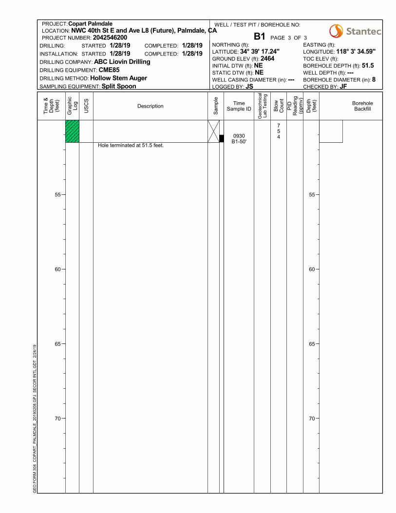
Hole terminated at 51.5 feet.
7540930
B1-50'
PAGE 3 OF 3
US
CS
Gra
phic
Log
COMPLETED:
COMPLETED:
Description
DRILLING COMPANY: ABC Liovin DrillingDRILLING EQUIPMENT: CME85DRILLING METHOD: Hollow Stem AugerSAMPLING EQUIPMENT: Split Spoon
1/28/191/28/19
1/28/191/28/19
CHECKED BY: JF
LONGITUDE: 118° 3' 34.59"T
ime
&D
epth
(fee
t)
55
60
65
70
PROJECT NUMBER: 2042546200DRILLING:
INSTALLATION:
STARTED
STARTED
LOGGED BY: JS
LATITUDE: 34° 39' 17.24"NORTHING (ft):
WELL CASING DIAMETER (in): ---
GROUND ELEV (ft): 2464
WELL DEPTH (ft): ---
EASTING (ft):
BOREHOLE DEPTH (ft): 51.5
BOREHOLE DIAMETER (in): 8
TOC ELEV (ft):
LOCATION: NWC 40th St E and Ave L8 (Future), Palmdale, CAPROJECT:Copart Palmdale
B1
INITIAL DTW (ft): NESTATIC DTW (ft): NE
WELL / TEST PIT / BOREHOLE NO:
GE
O F
OR
M 3
04
CO
PA
RT
_PA
LMD
ALE
_201
9020
8.G
PJ
SE
CO
R IN
TL.
GD
T
2/24
/19
BoreholeBackfillD
epth
(fee
t)
55
60
65
70
Blo
wC
ount
Geo
tech
nica
lLa
b T
estin
g
Sam
ple
TimeSample ID P
IDR
eadi
ng(p
pmv)
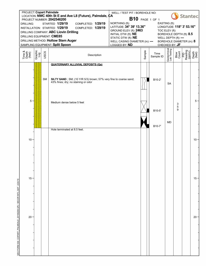
SM
QUATERNARY ALLUVIAL DEPOSITS (Qa)
SILTY SAND ; SM; (10 Y/R 5/3) brown; 57% very fine to coarse sand;43% fines; dry; no staining or odor
Medium dense below 5 feet
Hole terminated at 8.5 feet.
359
SA
MD
B10-2'
B10-5'
B10-7'
PAGE 1 OF 1
US
CS
Gra
phic
Log
COMPLETED:
COMPLETED:
Description
DRILLING COMPANY: ABC Liovin DrillingDRILLING EQUIPMENT: CME85DRILLING METHOD: Hollow Stem AugerSAMPLING EQUIPMENT: Split Spoon
1/29/191/29/19
1/29/191/29/19
CHECKED BY: JF
LONGITUDE: 118° 3' 53.16"T
ime
&D
epth
(fee
t)
5
10
15
20
PROJECT NUMBER: 2042546200DRILLING:
INSTALLATION:
STARTED
STARTED
LOGGED BY: ND
LATITUDE: 34° 39' 13.36"NORTHING (ft):
WELL CASING DIAMETER (in): ---
GROUND ELEV (ft): 2463
WELL DEPTH (ft): ---
EASTING (ft):
BOREHOLE DEPTH (ft): 8.5
BOREHOLE DIAMETER (in): 8
TOC ELEV (ft):
LOCATION: NWC 40th St E and Ave L8 (Future), Palmdale, CAPROJECT:Copart Palmdale
B10
INITIAL DTW (ft): NESTATIC DTW (ft): NE
WELL / TEST PIT / BOREHOLE NO:
GE
O F
OR
M 3
04
CO
PA
RT
_PA
LMD
ALE
_201
9020
8.G
PJ
SE
CO
R IN
TL.
GD
T
2/24
/19
Dep
th(f
eet)
5
10
15
20
Blo
wC
ount
Geo
tech
nica
lLa
b T
estin
g
Sam
ple
TimeSample ID P
IDR
eadi
ng(p
pmv)

SM
QUATERNARY ALLUVIAL DEPOSITS (Qa)
SILTY SAND ; SM; (10 Y/R 5/4) brown; 62% fine to coarse sand; 38%fines; dry; no staining or odor
Medium dense; moist below 5 feet
Hole terminated at 6.5 feet.
4814
SA
B11-2'
B11-5'
0
0
PAGE 1 OF 1
US
CS
Gra
phic
Log
COMPLETED:
COMPLETED:
Description
DRILLING COMPANY: ABC Liovin DrillingDRILLING EQUIPMENT: CME85DRILLING METHOD: Hollow Stem AugerSAMPLING EQUIPMENT: Split Spoon
1/29/191/29/19
1/29/191/29/19
CHECKED BY: JF
LONGITUDE: 118° 3' 58.58"T
ime
&D
epth
(fee
t)
5
10
15
20
PROJECT NUMBER: 2042546200DRILLING:
INSTALLATION:
STARTED
STARTED
LOGGED BY: ND
LATITUDE: 34° 39' 21.29"NORTHING (ft):
WELL CASING DIAMETER (in): ---
GROUND ELEV (ft): 2459
WELL DEPTH (ft): ---
EASTING (ft):
BOREHOLE DEPTH (ft): 6.5
BOREHOLE DIAMETER (in): 8
TOC ELEV (ft):
LOCATION: NWC 40th St E and Ave L8 (Future), Palmdale, CAPROJECT:Copart Palmdale
B11
INITIAL DTW (ft): NESTATIC DTW (ft): NE
WELL / TEST PIT / BOREHOLE NO:
GE
O F
OR
M 3
04
CO
PA
RT
_PA
LMD
ALE
_201
9020
8.G
PJ
SE
CO
R IN
TL.
GD
T
2/24
/19
Dep
th(f
eet)
5
10
15
20
Blo
wC
ount
Geo
tech
nica
lLa
b T
estin
g
Sam
ple
TimeSample ID P
IDR
eadi
ng(p
pmv)

SM
QUATERNARY ALLUVIAL DEPOSITS (Qa)
SILTY SAND ; SM; (10 Y/R 5/3) brown; 58% very fine to mediumgrained sand; 42% fines; dry; no staining or odor
Medium dense below 5 feet
(10 Y/R 7/4) pale brown below 7 feet
Hole terminated at 8.5 feet.
279
3810
MDD
SA
MD
B12-2'
B12-5'
B12-7'
PAGE 1 OF 1
US
CS
Gra
phic
Log
COMPLETED:
COMPLETED:
Description
DRILLING COMPANY: ABC Liovin DrillingDRILLING EQUIPMENT: CME85DRILLING METHOD: Hollow Stem AugerSAMPLING EQUIPMENT: Split Spoon
1/29/191/29/19
1/29/191/29/19
CHECKED BY: JF
LONGITUDE: 118° 3' 58.68"T
ime
&D
epth
(fee
t)
5
10
15
20
PROJECT NUMBER: 2042546200DRILLING:
INSTALLATION:
STARTED
STARTED
LOGGED BY: ND
LATITUDE: 34° 39' 16.18"NORTHING (ft):
WELL CASING DIAMETER (in): ---
GROUND ELEV (ft): 2461
WELL DEPTH (ft): ---
EASTING (ft):
BOREHOLE DEPTH (ft): 8.5
BOREHOLE DIAMETER (in): 8
TOC ELEV (ft):
LOCATION: NWC 40th St E and Ave L8 (Future), Palmdale, CAPROJECT:Copart Palmdale
B12
INITIAL DTW (ft): NESTATIC DTW (ft): NE
WELL / TEST PIT / BOREHOLE NO:
GE
O F
OR
M 3
04
CO
PA
RT
_PA
LMD
ALE
_201
9020
8.G
PJ
SE
CO
R IN
TL.
GD
T
2/24
/19
Dep
th(f
eet)
5
10
15
20
Blo
wC
ount
Geo
tech
nica
lLa
b T
estin
g
Sam
ple
TimeSample ID P
IDR
eadi
ng(p
pmv)

SM
SW-SM
SW
QUATERNARY ALLUVIAL DEPOSITS (Qa)
SILTY SAND ; SM; (10 Y/R 5/6) yellowish brown; 86% fine to coarsegrained sand; 14% fines; dry; medium dense; no staining or odor
Light gray; (10 Y/R 7/2) light gray below 5 feet
Dark yellowish brown; (10 Y/R 4/6) dark yellowish brown; 68% fine tocoarse grained sand; 32% fines
WELL GRADED SAND WITH SILT ; SW-SM; (10 Y/R 6/4) lightyellowish brown; 90% very fine to fine sand; 10% fines; dry; mediumdense; no staining or odor
WELL GRADED SAND ; SW; (10 Y/R 4/6) dark yellowish brown; 95%fine to coarse sand; 5% fines; moist; medium dense; no staining or odor
Hole terminated at 21.5 feet.
256
2615
357
2918
41012
SA
DS
MD
1010B2-2'
B2-5'
B2-7'
B2-10'
B2-15'
1045B2-20'
PAGE 1 OF 1
US
CS
Gra
phic
Log
COMPLETED:
COMPLETED:
Description
DRILLING COMPANY: ABC Liovin DrillingDRILLING EQUIPMENT: CME85DRILLING METHOD: Hollow Stem AugerSAMPLING EQUIPMENT: Split Spoon
1/28/191/28/19
1/28/191/28/19
CHECKED BY: JF
LONGITUDE: 118° 3' 34.79"T
ime
&D
epth
(fee
t)
5
10
15
20
PROJECT NUMBER: 2042546200DRILLING:
INSTALLATION:
STARTED
STARTED
LOGGED BY: ND
LATITUDE: 34° 39' 16.29"NORTHING (ft):
WELL CASING DIAMETER (in): ---
GROUND ELEV (ft): 2464
WELL DEPTH (ft): ---
EASTING (ft):
BOREHOLE DEPTH (ft): 21.5
BOREHOLE DIAMETER (in): 8
TOC ELEV (ft):
LOCATION: NWC 40th St E and Ave L8 (Future), Palmdale, CAPROJECT:Copart Palmdale
B2
INITIAL DTW (ft): NESTATIC DTW (ft): NE
WELL / TEST PIT / BOREHOLE NO:
GE
O F
OR
M 3
04
CO
PA
RT
_PA
LMD
ALE
_201
9020
8.G
PJ
SE
CO
R IN
TL.
GD
T
2/24
/19
Dep
th(f
eet)
5
10
15
20
Blo
wC
ount
Geo
tech
nica
lLa
b T
estin
g
Sam
ple
TimeSample ID P
IDR
eadi
ng(p
pmv)

SM
QUATERNARY ALLUVIAL DEPOSITS (Qa)
SILTY SAND ; SM; (10 Y/R 5/3) brown; 53% fine to medium grainedsand; 47% fines; dry; no staining or odor
65% very fine to fine sand; 35% fines; dry; loose below 5 feet
Hole terminated at 6.5 feet.
248
SA
MD
B3-2'
B3-5'
PAGE 1 OF 1
US
CS
Gra
phic
Log
COMPLETED:
COMPLETED:
Description
DRILLING COMPANY: ABC Liovin DrillingDRILLING EQUIPMENT: CME85DRILLING METHOD: Hollow Stem AugerSAMPLING EQUIPMENT: Split Spoon
1/29/191/29/19
1/29/191/29/19
CHECKED BY: JF
LONGITUDE: 118° 3' 40.65"T
ime
&D
epth
(fee
t)
5
10
15
20
PROJECT NUMBER: 2042546200DRILLING:
INSTALLATION:
STARTED
STARTED
LOGGED BY: ND
LATITUDE: 34° 39' 23.76"NORTHING (ft):
WELL CASING DIAMETER (in): ---
GROUND ELEV (ft): 2459
WELL DEPTH (ft): ---
EASTING (ft):
BOREHOLE DEPTH (ft): 6.5
BOREHOLE DIAMETER (in): 8
TOC ELEV (ft):
LOCATION: NWC 40th St E and Ave L8 (Future), Palmdale, CAPROJECT:Copart Palmdale
B3
INITIAL DTW (ft): NESTATIC DTW (ft): NE
WELL / TEST PIT / BOREHOLE NO:
GE
O F
OR
M 3
04
CO
PA
RT
_PA
LMD
ALE
_201
9020
8.G
PJ
SE
CO
R IN
TL.
GD
T
2/24
/19
Dep
th(f
eet)
5
10
15
20
Blo
wC
ount
Geo
tech
nica
lLa
b T
estin
g
Sam
ple
TimeSample ID P
IDR
eadi
ng(p
pmv)
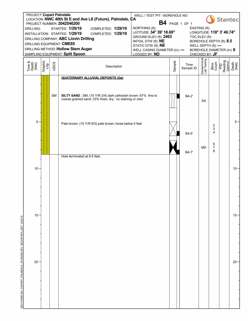
SM
QUATERNARY ALLUVIAL DEPOSITS (Qa)
SILTY SAND ; SM; (10 Y/R 3/4) dark yellowish brown; 67% fine tocoarse grained sand; 33% fines; dry; no staining or odor
Pale brown; (10 Y/R 6/3) pale brown; loose below 5 feet
Hole terminated at 8.5 feet.
234
678
SA
MD
B4-2'
B4-5'
B4-7'
PAGE 1 OF 1
US
CS
Gra
phic
Log
COMPLETED:
COMPLETED:
Description
DRILLING COMPANY: ABC Liovin DrillingDRILLING EQUIPMENT: CME85DRILLING METHOD: Hollow Stem AugerSAMPLING EQUIPMENT: Split Spoon
1/29/191/29/19
1/29/191/29/19
CHECKED BY: JF
LONGITUDE: 118° 3' 40.74"T
ime
&D
epth
(fee
t)
5
10
15
20
PROJECT NUMBER: 2042546200DRILLING:
INSTALLATION:
STARTED
STARTED
LOGGED BY: ND
LATITUDE: 34° 39' 18.69"NORTHING (ft):
WELL CASING DIAMETER (in): ---
GROUND ELEV (ft): 2463
WELL DEPTH (ft): ---
EASTING (ft):
BOREHOLE DEPTH (ft): 8.5
BOREHOLE DIAMETER (in): 8
TOC ELEV (ft):
LOCATION: NWC 40th St E and Ave L8 (Future), Palmdale, CAPROJECT:Copart Palmdale
B4
INITIAL DTW (ft): NESTATIC DTW (ft): NE
WELL / TEST PIT / BOREHOLE NO:
GE
O F
OR
M 3
04
CO
PA
RT
_PA
LMD
ALE
_201
9020
8.G
PJ
SE
CO
R IN
TL.
GD
T
2/24
/19
Dep
th(f
eet)
5
10
15
20
Blo
wC
ount
Geo
tech
nica
lLa
b T
estin
g
Sam
ple
TimeSample ID P
IDR
eadi
ng(p
pmv)

SM
QUATERNARY ALLUVIAL DEPOSITS (Qa)
SILTY SAND ; SM; (10 Y/R 5/6) yellowish brown; 58% fine to very finegrained sand; 42% fines; dry; no staining or odor
(10 Y/R 6/6) brownish yellow; loose below 5 feet
Hole terminated at 6.5 feet.
487
SA
MD
B5-2'
B5-5'
PAGE 1 OF 1
US
CS
Gra
phic
Log
COMPLETED:
COMPLETED:
Description
DRILLING COMPANY: ABC Liovin DrillingDRILLING EQUIPMENT: CME85DRILLING METHOD: Hollow Stem AugerSAMPLING EQUIPMENT: Split Spoon
1/29/191/29/19
1/29/191/29/19
CHECKED BY: JF
LONGITUDE: 118° 3' 40.67"T
ime
&D
epth
(fee
t)
5
10
15
20
PROJECT NUMBER: 2042546200DRILLING:
INSTALLATION:
STARTED
STARTED
LOGGED BY: ND
LATITUDE: 34° 39' 13.46"NORTHING (ft):
WELL CASING DIAMETER (in): ---
GROUND ELEV (ft): 2464
WELL DEPTH (ft): ---
EASTING (ft):
BOREHOLE DEPTH (ft): 6.5
BOREHOLE DIAMETER (in): 8
TOC ELEV (ft):
LOCATION: NWC 40th St E and Ave L8 (Future), Palmdale, CAPROJECT:Copart Palmdale
B5
INITIAL DTW (ft): NESTATIC DTW (ft): NE
WELL / TEST PIT / BOREHOLE NO:
GE
O F
OR
M 3
04
CO
PA
RT
_PA
LMD
ALE
_201
9020
8.G
PJ
SE
CO
R IN
TL.
GD
T
2/24
/19
Dep
th(f
eet)
5
10
15
20
Blo
wC
ount
Geo
tech
nica
lLa
b T
estin
g
Sam
ple
TimeSample ID P
IDR
eadi
ng(p
pmv)

SM
QUATERNARY ALLUVIAL DEPOSITS (Qa)
SILTY SAND ; SM; (10 Y/R 5/6) yellowish brown; 80% very fine to finegrained sand; 20% fines; dry; no staining or odor
Loose below 5 feet
Medium dense below 7 feet
Hole terminated at 8.5 feet.
334
81415
R-VAL
SA
MD
B6-2'
B6-5'
B6-7'
PAGE 1 OF 1
US
CS
Gra
phic
Log
COMPLETED:
COMPLETED:
Description
DRILLING COMPANY: ABC Liovin DrillingDRILLING EQUIPMENT: CME85DRILLING METHOD: Hollow Stem AugerSAMPLING EQUIPMENT: Split Spoon
1/29/191/29/19
1/29/191/29/19
CHECKED BY: JF
LONGITUDE: 118° 3' 47.25"T
ime
&D
epth
(fee
t)
5
10
15
20
PROJECT NUMBER: 2042546200DRILLING:
INSTALLATION:
STARTED
STARTED
LOGGED BY: ND
LATITUDE: 34° 39' 21.13"NORTHING (ft):
WELL CASING DIAMETER (in): ---
GROUND ELEV (ft): 2460
WELL DEPTH (ft): ---
EASTING (ft):
BOREHOLE DEPTH (ft): 8.5
BOREHOLE DIAMETER (in): 8
TOC ELEV (ft):
LOCATION: NWC 40th St E and Ave L8 (Future), Palmdale, CAPROJECT:Copart Palmdale
B6
INITIAL DTW (ft): NESTATIC DTW (ft): NE
WELL / TEST PIT / BOREHOLE NO:
GE
O F
OR
M 3
04
CO
PA
RT
_PA
LMD
ALE
_201
9020
8.G
PJ
SE
CO
R IN
TL.
GD
T
2/24
/19
Dep
th(f
eet)
5
10
15
20
Blo
wC
ount
Geo
tech
nica
lLa
b T
estin
g
Sam
ple
TimeSample ID P
IDR
eadi
ng(p
pmv)

ML
SM
QUATERNARY ALLUVIAL DEPOSITS (Qa)
SANDY SILT ; ML; (10 Y/R 6/4) light yellowish brown; 47% very fine tomedium grained sand; 53% fines; dry; no staining or odor
SILTY SAND ; SM; (10 Y/R 6/4) light yellowish brown; 75% very fine tomedium grained sand; 25% fines; dry; no staining or odor
Hole terminated at 6.5 feet.
SA
MD
B7-2'
B7-5'
PAGE 1 OF 1
US
CS
Gra
phic
Log
COMPLETED:
COMPLETED:
Description
DRILLING COMPANY: ABC Liovin DrillingDRILLING EQUIPMENT: CME85DRILLING METHOD: Hollow Stem AugerSAMPLING EQUIPMENT: Split Spoon
1/29/191/29/19
1/29/191/29/19
CHECKED BY: JF
LONGITUDE: 118° 3' 47.23"T
ime
&D
epth
(fee
t)
5
10
15
20
PROJECT NUMBER: 2042546200DRILLING:
INSTALLATION:
STARTED
STARTED
LOGGED BY: ND
LATITUDE: 34° 39' 16.35"NORTHING (ft):
WELL CASING DIAMETER (in): ---
GROUND ELEV (ft): 2462
WELL DEPTH (ft): ---
EASTING (ft):
BOREHOLE DEPTH (ft): 6.5
BOREHOLE DIAMETER (in): 8
TOC ELEV (ft):
LOCATION: NWC 40th St E and Ave L8 (Future), Palmdale, CAPROJECT:Copart Palmdale
B7
INITIAL DTW (ft): NESTATIC DTW (ft): NE
WELL / TEST PIT / BOREHOLE NO:
GE
O F
OR
M 3
04
CO
PA
RT
_PA
LMD
ALE
_201
9020
8.G
PJ
SE
CO
R IN
TL.
GD
T
2/24
/19
Dep
th(f
eet)
5
10
15
20
Blo
wC
ount
Geo
tech
nica
lLa
b T
estin
g
Sam
ple
TimeSample ID P
IDR
eadi
ng(p
pmv)

SM
QUATERNARY ALLUVIAL DEPOSITS (Qa)
SILTY SAND ; SM; (10 Y/R 6/4) light yellowish brown; 85% very fine tofine sand; 15% fines; dry; no staining or odor
(10 Y/R 6/3) pale brown; medium dense below 5 feet
Loose below 7 feet
Hole terminated at 8.5 feet.
355
156
SA
MD
B8-2'
B8-5'
B8-7'
PAGE 1 OF 1
US
CS
Gra
phic
Log
COMPLETED:
COMPLETED:
Description
DRILLING COMPANY: ABC Liovin DrillingDRILLING EQUIPMENT: CME85DRILLING METHOD: Hollow Stem AugerSAMPLING EQUIPMENT: Split Spoon
1/29/191/29/19
1/29/191/29/19
CHECKED BY: JF
LONGITUDE: 118° 3' 53.53"T
ime
&D
epth
(fee
t)
5
10
15
20
PROJECT NUMBER: 2042546200DRILLING:
INSTALLATION:
STARTED
STARTED
LOGGED BY: ND
LATITUDE: 34° 39' 23.66"NORTHING (ft):
WELL CASING DIAMETER (in): ---
GROUND ELEV (ft): 2459
WELL DEPTH (ft): ---
EASTING (ft):
BOREHOLE DEPTH (ft): 8.5
BOREHOLE DIAMETER (in): 8
TOC ELEV (ft):
LOCATION: NWC 40th St E and Ave L8 (Future), Palmdale, CAPROJECT:Copart Palmdale
B8
INITIAL DTW (ft): NESTATIC DTW (ft): NE
WELL / TEST PIT / BOREHOLE NO:
GE
O F
OR
M 3
04
CO
PA
RT
_PA
LMD
ALE
_201
9020
8.G
PJ
SE
CO
R IN
TL.
GD
T
2/24
/19
Dep
th(f
eet)
5
10
15
20
Blo
wC
ount
Geo
tech
nica
lLa
b T
estin
g
Sam
ple
TimeSample ID P
IDR
eadi
ng(p
pmv)

SM
QUATERNARY ALLUVIAL DEPOSITS (Qa)
SILTY SAND ; SM; (10 Y/R 5/3) brown; 54% very fine to coarse sand;46% fines; dry; no staining or odor
Medium dense below 5 feet
Hole terminated at 6.5 feet.
4812
SA
MD
B9-2'
B9-5'
PAGE 1 OF 1
US
CS
Gra
phic
Log
COMPLETED:
COMPLETED:
Description
DRILLING COMPANY: ABC Liovin DrillingDRILLING EQUIPMENT: CME85DRILLING METHOD: Hollow Stem AugerSAMPLING EQUIPMENT: Split Spoon
1/29/191/29/19
1/29/191/29/19
CHECKED BY: JF
LONGITUDE: 118° 3' 53.33"T
ime
&D
epth
(fee
t)
5
10
15
20
PROJECT NUMBER: 2042546200DRILLING:
INSTALLATION:
STARTED
STARTED
LOGGED BY: ND
LATITUDE: 34° 39' 18.71"NORTHING (ft):
WELL CASING DIAMETER (in): ---
GROUND ELEV (ft): 2461
WELL DEPTH (ft): ---
EASTING (ft):
BOREHOLE DEPTH (ft): 6.5
BOREHOLE DIAMETER (in): 8
TOC ELEV (ft):
LOCATION: NWC 40th St E and Ave L8 (Future), Palmdale, CAPROJECT:Copart Palmdale
B9
INITIAL DTW (ft): NESTATIC DTW (ft): NE
WELL / TEST PIT / BOREHOLE NO:
GE
O F
OR
M 3
04
CO
PA
RT
_PA
LMD
ALE
_201
9020
8.G
PJ
SE
CO
R IN
TL.
GD
T
2/24
/19
Dep
th(f
eet)
5
10
15
20
Blo
wC
ount
Geo
tech
nica
lLa
b T
estin
g
Sam
ple
TimeSample ID P
IDR
eadi
ng(p
pmv)

SP-SM
QUATERNARY ALLUVIAL DEPOSITS (Qa)
POORLY GRADED SAND WITH SILT ;SP-SM; (10 Y/R 4/3) brown; 90% fine tocoarse grained sand; 10% fines; dry; nostaining or odor
(10 Y/R 6/2) light brownish gray; 2% finegravel; 89% very fine to coarse grained sand;9% fines; medium dense below 5 feet
Hole terminated at 6.5 feet.
Backfilledwith #3 LoneStar Sand
8913
SA,MD
0820P1-2'
0845P1-5'
PAGE 1 OF 1
US
CS
Gra
phic
Log
COMPLETED:
COMPLETED:
Description
DRILLING COMPANY: ABC Liovin DrillingDRILLING EQUIPMENT: CME85DRILLING METHOD: Hollow Stem AugerSAMPLING EQUIPMENT: Split Spoon
1/28/191/28/19
1/29/191/29/19
CHECKED BY: JF
LONGITUDE: 118° 3' 33.69"T
ime
&D
epth
(fee
t)
5
10
15
20
PROJECT NUMBER: 2042546200DRILLING:
INSTALLATION:
STARTED
STARTED
LOGGED BY: ND
LATITUDE: 34° 39' 24.61"NORTHING (ft):
WELL CASING DIAMETER (in): 2
GROUND ELEV (ft): 2460
WELL DEPTH (ft): 6.5
EASTING (ft):
BOREHOLE DEPTH (ft): 6.5
BOREHOLE DIAMETER (in): 8
TOC ELEV (ft):
LOCATION: NWC 40th St E and Ave L8 (Future), Palmdale, CAPROJECT:Copart Palmdale
P1
INITIAL DTW (ft): NESTATIC DTW (ft): NE
WELL / TEST PIT / BOREHOLE NO:
GE
O F
OR
M 3
04
CO
PA
RT
_PA
LMD
ALE
_201
9020
8.G
PJ
SE
CO
R IN
TL.
GD
T
2/24
/19
WellConstructionD
epth
(fee
t)
5
10
15
20
Blo
wC
ount
Geo
tech
nica
lLa
b T
estin
g
Sam
ple
TimeSample ID P
IDR
eadi
ng(p
pmv)

SM
QUATERNARY ALLUVIAL DEPOSITS (Qa)
SILTY SAND ; SM; (2.5 Y/R 7/3) palebrown; 65% very fine to fine sand; 35% fines;dry; no staining or odor
Light olive brown; (2.5 Y/R 5/4) light olivebrown; 77% very fine to coarse grained sand;23% fines; loose below 5 feet
Hole terminated at 6.5 feet.
Backfilledwith #3 LoneStar Sand
344
SA
P2-2'
P2-5'
PAGE 1 OF 1
US
CS
Gra
phic
Log
COMPLETED:
COMPLETED:
Description
DRILLING COMPANY: ABC Liovin DrillingDRILLING EQUIPMENT: CME85DRILLING METHOD: Hollow Stem AugerSAMPLING EQUIPMENT: Split Spoon
1/28/191/28/19
1/28/191/28/19
CHECKED BY: JF
LONGITUDE: 118° 4' 2.97"T
ime
&D
epth
(fee
t)
5
10
15
20
PROJECT NUMBER: 2042546200DRILLING:
INSTALLATION:
STARTED
STARTED
LOGGED BY: JS
LATITUDE: 34° 39' 24.67"NORTHING (ft):
WELL CASING DIAMETER (in): 2
GROUND ELEV (ft): 2457
WELL DEPTH (ft): 6.5
EASTING (ft):
BOREHOLE DEPTH (ft): 6.5
BOREHOLE DIAMETER (in): 8
TOC ELEV (ft):
LOCATION: NWC 40th St E and Ave L8 (Future), Palmdale, CAPROJECT:Copart Palmdale
P2
INITIAL DTW (ft): NESTATIC DTW (ft): NE
WELL / TEST PIT / BOREHOLE NO:
GE
O F
OR
M 3
04
CO
PA
RT
_PA
LMD
ALE
_201
9020
8.G
PJ
SE
CO
R IN
TL.
GD
T
2/24
/19
WellConstructionD
epth
(fee
t)
5
10
15
20
Blo
wC
ount
Geo
tech
nica
lLa
b T
estin
g
Sam
ple
TimeSample ID P
IDR
eadi
ng(p
pmv)

SM
QUATERNARY ALLUVIAL DEPOSITS (Qa)
SILTY SAND ; SM; (10 Y/R 4/6) darkyellowish brown; 85% very fine to finegrained sand; 15% fines; dry; no staining orodor
(10 Y/R 3/6) dark yellowish brown; 74% fineto medium grained sand; 26% fines; mediumdense below 5 feet
Hole terminated at 6.5 feet.
Backfilledwith #3 LoneStar Sand
2810
SA,MD
P3-2'
P3-5'
PAGE 1 OF 1
US
CS
Gra
phic
Log
COMPLETED:
COMPLETED:
Description
DRILLING COMPANY: ABC Liovin DrillingDRILLING EQUIPMENT: CME85DRILLING METHOD: Hollow Stem AugerSAMPLING EQUIPMENT: Split Spoon
1/28/191/28/19
1/28/191/28/19
CHECKED BY: JF
LONGITUDE: 118° 4' 3.04"T
ime
&D
epth
(fee
t)
5
10
15
20
PROJECT NUMBER: 2042546200DRILLING:
INSTALLATION:
STARTED
STARTED
LOGGED BY: ND
LATITUDE: 34° 39' 12.47"NORTHING (ft):
WELL CASING DIAMETER (in): 2
GROUND ELEV (ft): 2464
WELL DEPTH (ft): 6.5
EASTING (ft):
BOREHOLE DEPTH (ft): 6.5
BOREHOLE DIAMETER (in): 8
TOC ELEV (ft):
LOCATION: NWC 40th St E and Ave L8 (Future), Palmdale, CAPROJECT:Copart Palmdale
P3
INITIAL DTW (ft): NESTATIC DTW (ft): NE
WELL / TEST PIT / BOREHOLE NO:
GE
O F
OR
M 3
04
CO
PA
RT
_PA
LMD
ALE
_201
9020
8.G
PJ
SE
CO
R IN
TL.
GD
T
2/24
/19
WellConstructionD
epth
(fee
t)
5
10
15
20
Blo
wC
ount
Geo
tech
nica
lLa
b T
estin
g
Sam
ple
TimeSample ID P
IDR
eadi
ng(p
pmv)

SW-SM
QUATERNARY ALLUVIAL DEPOSITS (Qa)
WELL GRADED SAND WITH SILT ;SW-SM; (10 Y/R 5/6) yellowish brown; 95%very fine to fine sand; 5% fines; dry; nostaining or odor
(10 Y/R 3/3) dark brown; 5% fine gravel; 84%fine to coarse sand; 11% fines; mediumdense below 5 feet
Hole terminated at 6.5 feet.
Backfilledwith #3 LoneStar Sand
578
SA
P4-2'
P4-5'
PAGE 1 OF 1
US
CS
Gra
phic
Log
COMPLETED:
COMPLETED:
Description
DRILLING COMPANY: ABC Liovin DrillingDRILLING EQUIPMENT: CME85DRILLING METHOD: Hollow Stem AugerSAMPLING EQUIPMENT: Split Spoon
1/28/191/28/19
1/28/191/28/19
CHECKED BY: JF
LONGITUDE: 118° 3' 33.29"T
ime
&D
epth
(fee
t)
5
10
15
20
PROJECT NUMBER: 2042546200DRILLING:
INSTALLATION:
STARTED
STARTED
LOGGED BY: JS
LATITUDE: 34° 39' 12.31"NORTHING (ft):
WELL CASING DIAMETER (in): 2
GROUND ELEV (ft): 2465
WELL DEPTH (ft): 6.5
EASTING (ft):
BOREHOLE DEPTH (ft): 6.5
BOREHOLE DIAMETER (in): 8
TOC ELEV (ft):
LOCATION: NWC 40th St E and Ave L8 (Future), Palmdale, CAPROJECT:Copart Palmdale
P4
INITIAL DTW (ft): NESTATIC DTW (ft): NE
WELL / TEST PIT / BOREHOLE NO:
GE
O F
OR
M 3
04
CO
PA
RT
_PA
LMD
ALE
_201
9020
8.G
PJ
SE
CO
R IN
TL.
GD
T
2/24
/19
WellConstructionD
epth
(fee
t)
5
10
15
20
Blo
wC
ount
Geo
tech
nica
lLa
b T
estin
g
Sam
ple
TimeSample ID P
IDR
eadi
ng(p
pmv)

APPENDIX B LABORATORY TEST RESULTS

SUMMARY OF SOIL DENSITY TEST RESULTS ASTM D 2216
Boring Location
Sample Depth
(ft)
Wet Density (lb/ft3)
Dry Density (lb/ft3)
Moisture Content
(percent)
B1-10’ 10 96.1 92.4 4.0
B1-20’ 20 109.3 107.8 1.4
B2-15’ 15 117.6 115.8 1.5
B3-5’ 5 105.5 104.5 0.9
B4-7’ 7 103.7 102.1 1.6
B5-5’ 5 109.2 108.5 0.6
B6-7’ 7 108.0 104.9 2.9
B7-5’ 5 103.4 100.8 2.6
B8-7’ 7 103.9 102.3 1.6
B9-5’ 5 105.1 103.7 1.3
B10-7’ 7 101.4 99.6 1.9
B12-7’ 7 95.6 91.4 4.5
P1-5’ 5 101.9 101.2 0.7
P3-5’ 5 109.1 104.4 4.5

Gradation AnalysisASTM D 422
Project Name Copart Palmdale Project Number 2042546200Source Grab Lab ID B1-2'
Date Received 02-01-2019Preparation Method ASTM D 1140 Method A Preparation Date 02-04-2019
Particle Shape Test Date 02-05-2019Particle Hardness
Sample Dry Mass (g) 359.50 Analysis based on total sample.Moisture Content (%) 1.6
Grams % % % Gravel 0.0Sieve Size Retained Retained Passing % Sand 74.2
% Fines 25.8Fines Classification ML
D10 (mm) N/AD30 (mm) N/AD60 (mm) N/A
Cu N/ACc N/A
No. 8 1.10 0.3 99.7No. 16 5.80 1.6 98.1 ClassificationNo. 30 9.30 2.6 95.5No. 50 29.00 8.1 87.4No. 100 107.00 29.8 57.7No. 200 114.50 31.8 25.8
Pan 92.80 25.8 ---
CommentsReviewed By
Silty Sand (SM)
Classification determined by ASTM D 2487. -200 material classification determined by visual assessment, ASTM D 2488.
6 3 2 1 3/4 3/8 4 10 16 30 40 100 200
0.00
10.00
20.00
30.00
40.00
50.00
60.00
70.00
80.00
90.00
100.00
0.0010.010.11101001000
Perc
ent P
assi
ng
Diameter (mm)
Particle Size DistributionSieve Size in inches Sieve Size in sieve numbers
File: Copart_Palmdale_2042546200_B1-2_Sieve.xlsm Sheet: ReportPreparation Date: 1-2008Revision Date: 4-2008 Stantec Consulting Services Inc.
Laboratory DocumentPrepared By: JW
Approved By: TLK
JF

Gradation AnalysisASTM D 422
Project Name Copart Palmdale Project Number 2042546200Source CalMod Lab ID B1-5'
Date Received 02-01-2019Preparation Method ASTM D 1140 Method A Preparation Date 02-04-2019
Particle Shape Test Date 02-05-2019Particle Hardness
Sample Dry Mass (g) 312.10 Analysis based on total sample.Moisture Content (%) 3.3
Grams % % % Gravel 0.0Sieve Size Retained Retained Passing % Sand 77.9
% Fines 22.1Fines Classification ML
D10 (mm) N/AD30 (mm) N/AD60 (mm) N/A
Cu N/ACc N/A
No. 8 2.80 0.9 99.1No. 16 8.80 2.8 96.3 ClassificationNo. 30 16.70 5.4 90.9No. 50 42.40 13.6 77.3No. 100 98.90 31.7 45.7No. 200 73.50 23.6 22.1
Pan 69.00 22.1 ---
CommentsReviewed By
Silty Sand (SM)
Classification determined by ASTM D 2487. -200 material classification determined by visual assessment, ASTM D 2488.
6 3 2 1 3/4 3/8 4 10 16 30 40 100 200
0.00
10.00
20.00
30.00
40.00
50.00
60.00
70.00
80.00
90.00
100.00
0.0010.010.11101001000
Perc
ent P
assi
ng
Diameter (mm)
Particle Size DistributionSieve Size in inches Sieve Size in sieve numbers
File: Copart_Palmdale_2042546200_B1-5_Sieve.xlsm Sheet: ReportPreparation Date: 1-2008Revision Date: 4-2008 Stantec Consulting Services Inc.
Laboratory DocumentPrepared By: JW
Approved By: TLK
JF

Gradation AnalysisASTM D 422
Project Name Copart Palmdale Project Number 2042546200Source Grab Lab ID B2-2'
Date Received 02-01-2019Preparation Method ASTM D 1140 Method A Preparation Date 02-04-2019
Particle Shape Test Date 02-05-2019Particle Hardness
Sample Dry Mass (g) 395.40 Analysis based on total sample.Moisture Content (%) 1.3
Grams % % % Gravel 0.3Sieve Size Retained Retained Passing % Sand 85.3
% Fines 14.4Fines Classification ML
D10 (mm) N/AD30 (mm) N/AD60 (mm) N/A
Cu N/ANo. 4 1.20 0.3 99.7 Cc N/ANo. 8 3.20 0.8 98.9No. 16 10.20 2.6 96.3 ClassificationNo. 30 24.20 6.1 90.2No. 50 84.70 21.4 68.8No. 100 133.20 33.7 35.1No. 200 81.60 20.6 14.4
Pan 57.10 14.4 ---
CommentsReviewed By
Silty Sand (SM)
Classification determined by ASTM D 2487. -200 material classification determined by visual assessment, ASTM D 2488.
6 3 2 1 3/4 3/8 4 10 16 30 40 100 200
0.00
10.00
20.00
30.00
40.00
50.00
60.00
70.00
80.00
90.00
100.00
0.0010.010.11101001000
Perc
ent P
assi
ng
Diameter (mm)
Particle Size DistributionSieve Size in inches Sieve Size in sieve numbers
File: Copart_Palmdale_2042546200_B2-2_Sieve.xlsm Sheet: ReportPreparation Date: 1-2008Revision Date: 4-2008 Stantec Consulting Services Inc.
Laboratory DocumentPrepared By: JW
Approved By: TLK
JF

Gradation AnalysisASTM D 422
Project Name Copart Palmdale Project Number 2042546200Source SPT Lab ID B2-10'
Date Received 02-01-2019Preparation Method ASTM D 1140 Method A Preparation Date 02-05-2019
Particle Shape Test Date 02-06-2019Particle Hardness
Sample Dry Mass (g) 374.60 Analysis based on total sample.Moisture Content (%) 3.0
Grams % % % Gravel 0.3Sieve Size Retained Retained Passing % Sand 68.0
% Fines 31.7Fines Classification ML
D10 (mm) N/AD30 (mm) N/AD60 (mm) N/A
Cu N/ANo. 4 1.20 0.3 99.7 Cc N/ANo. 8 8.20 2.2 97.5No. 16 20.40 5.4 92.0 ClassificationNo. 30 26.90 7.2 84.9No. 50 34.00 9.1 75.8No. 100 81.70 21.8 54.0No. 200 83.60 22.3 31.7
Pan 118.60 31.7 ---
CommentsReviewed By
Silty Sand (SM)
Classification determined by ASTM D 2487. -200 material classification determined by visual assessment, ASTM D 2488.
6 3 2 1 3/4 3/8 4 10 16 30 40 100 200
0.00
10.00
20.00
30.00
40.00
50.00
60.00
70.00
80.00
90.00
100.00
0.0010.010.11101001000
Perc
ent P
assi
ng
Diameter (mm)
Particle Size DistributionSieve Size in inches Sieve Size in sieve numbers
File: Copart_Palmdale_2042546200_B2-10_Sieve.xlsm Sheet: ReportPreparation Date: 1-2008Revision Date: 4-2008 Stantec Consulting Services Inc.
Laboratory DocumentPrepared By: JW
Approved By: TLK
JF

Gradation AnalysisASTM D 422
Project Name Copart Palmdale Project Number 2042546200Source Grab Lab ID B3-2'
Date Received 02-01-2019Preparation Method ASTM D 1140 Method A Preparation Date 02-04-2019
Particle Shape Test Date 02-05-2019Particle Hardness
Sample Dry Mass (g) 455.00 Analysis based on total sample.Moisture Content (%) 1.8
Grams % % % Gravel 0.0Sieve Size Retained Retained Passing % Sand 52.8
% Fines 47.2Fines Classification ML
D10 (mm) N/AD30 (mm) N/AD60 (mm) N/A
Cu N/ACc N/A
No. 8 0.30 0.1 99.9No. 16 2.10 0.5 99.5 ClassificationNo. 30 4.70 1.0 98.4No. 50 28.80 6.3 92.1No. 100 81.00 17.8 74.3No. 200 123.30 27.1 47.2
Pan 214.80 47.2 ---
CommentsReviewed By
Silty Sand (SM)
Classification determined by ASTM D 2487. -200 material classification determined by visual assessment, ASTM D 2488.
6 3 2 1 3/4 3/8 4 10 16 30 40 100 200
0.00
10.00
20.00
30.00
40.00
50.00
60.00
70.00
80.00
90.00
100.00
0.0010.010.11101001000
Perc
ent P
assi
ng
Diameter (mm)
Particle Size DistributionSieve Size in inches Sieve Size in sieve numbers
File: Copart_Palmdale_2042546200_B3-2_Sieve.xlsm Sheet: ReportPreparation Date: 1-2008Revision Date: 4-2008 Stantec Consulting Services Inc.
Laboratory DocumentPrepared By: JW
Approved By: TLK
JF
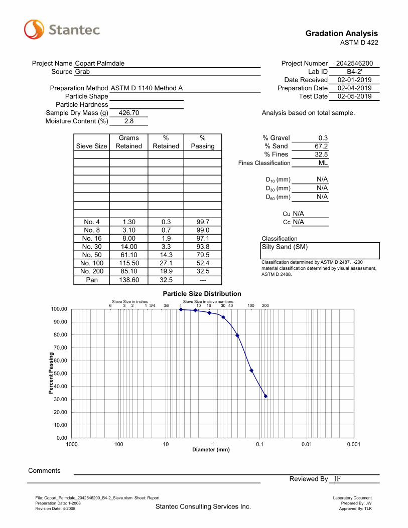
Gradation AnalysisASTM D 422
Project Name Copart Palmdale Project Number 2042546200Source Grab Lab ID B4-2'
Date Received 02-01-2019Preparation Method ASTM D 1140 Method A Preparation Date 02-04-2019
Particle Shape Test Date 02-05-2019Particle Hardness
Sample Dry Mass (g) 426.70 Analysis based on total sample.Moisture Content (%) 2.8
Grams % % % Gravel 0.3Sieve Size Retained Retained Passing % Sand 67.2
% Fines 32.5Fines Classification ML
D10 (mm) N/AD30 (mm) N/AD60 (mm) N/A
Cu N/ANo. 4 1.30 0.3 99.7 Cc N/ANo. 8 3.10 0.7 99.0No. 16 8.00 1.9 97.1 ClassificationNo. 30 14.00 3.3 93.8No. 50 61.10 14.3 79.5No. 100 115.50 27.1 52.4No. 200 85.10 19.9 32.5
Pan 138.60 32.5 ---
CommentsReviewed By
Silty Sand (SM)
Classification determined by ASTM D 2487. -200 material classification determined by visual assessment, ASTM D 2488.
6 3 2 1 3/4 3/8 4 10 16 30 40 100 200
0.00
10.00
20.00
30.00
40.00
50.00
60.00
70.00
80.00
90.00
100.00
0.0010.010.11101001000
Perc
ent P
assi
ng
Diameter (mm)
Particle Size DistributionSieve Size in inches Sieve Size in sieve numbers
File: Copart_Palmdale_2042546200_B4-2_Sieve.xlsm Sheet: ReportPreparation Date: 1-2008Revision Date: 4-2008 Stantec Consulting Services Inc.
Laboratory DocumentPrepared By: JW
Approved By: TLK
JF

Gradation AnalysisASTM D 422
Project Name Copart Palmdale Project Number 2042546200Source Grab Lab ID B5-2'
Date Received 02-01-2019Preparation Method ASTM D 1140 Method A Preparation Date 02-05-2019
Particle Shape Test Date 02-06-2019Particle Hardness
Sample Dry Mass (g) 455.20 Analysis based on total sample.Moisture Content (%) 2.6
Grams % % % Gravel 0.0Sieve Size Retained Retained Passing % Sand 57.5
% Fines 42.5Fines Classification ML
D10 (mm) N/AD30 (mm) N/AD60 (mm) N/A
Cu N/ACc N/A
No. 8 1.40 0.3 99.7No. 16 6.80 1.5 98.2 ClassificationNo. 30 11.40 2.5 95.7No. 50 27.90 6.1 89.6No. 100 92.20 20.3 69.3No. 200 121.90 26.8 42.5
Pan 193.60 42.5 ---
CommentsReviewed By
Silty Sand (SM)
Classification determined by ASTM D 2487. -200 material classification determined by visual assessment, ASTM D 2488.
6 3 2 1 3/4 3/8 4 10 16 30 40 100 200
0.00
10.00
20.00
30.00
40.00
50.00
60.00
70.00
80.00
90.00
100.00
0.0010.010.11101001000
Perc
ent P
assi
ng
Diameter (mm)
Particle Size DistributionSieve Size in inches Sieve Size in sieve numbers
File: Copart_Palmdale_2042546200_B5-2_Sieve.xlsm Sheet: ReportPreparation Date: 1-2008Revision Date: 4-2008 Stantec Consulting Services Inc.
Laboratory DocumentPrepared By: JW
Approved By: TLK
JF

Gradation AnalysisASTM D 422
Project Name Copart Palmdale Project Number 2042546200Source Grab Lab ID B6-2'
Date Received 02-01-2019Preparation Method ASTM D 1140 Method A Preparation Date 02-05-2019
Particle Shape Test Date 02-06-2019Particle Hardness
Sample Dry Mass (g) 471.60 Analysis based on total sample.Moisture Content (%) 2.1
Grams % % % Gravel 0.4Sieve Size Retained Retained Passing % Sand 80.0
% Fines 19.6Fines Classification ML
D10 (mm) N/AD30 (mm) N/AD60 (mm) N/A
Cu N/ANo. 4 2.00 0.4 99.6 Cc N/ANo. 8 6.40 1.4 98.2No. 16 9.90 2.1 96.1 ClassificationNo. 30 16.90 3.6 92.5No. 50 95.00 20.1 72.4No. 100 157.40 33.4 39.0No. 200 91.50 19.4 19.6
Pan 92.50 19.6 ---
CommentsReviewed By
Silty Sand (SM)
Classification determined by ASTM D 2487. -200 material classification determined by visual assessment, ASTM D 2488.
6 3 2 1 3/4 3/8 4 10 16 30 40 100 200
0.00
10.00
20.00
30.00
40.00
50.00
60.00
70.00
80.00
90.00
100.00
0.0010.010.11101001000
Perc
ent P
assi
ng
Diameter (mm)
Particle Size DistributionSieve Size in inches Sieve Size in sieve numbers
File: Copart_Palmdale_2042546200_B6-2_Sieve.xlsm Sheet: ReportPreparation Date: 1-2008Revision Date: 4-2008 Stantec Consulting Services Inc.
Laboratory DocumentPrepared By: JW
Approved By: TLK
JF

Gradation AnalysisASTM D 422
Project Name Copart Palmdale Project Number 2042546200Source Grab Lab ID B7-2'
Date Received 02-01-2019Preparation Method ASTM D 1140 Method A Preparation Date 02-05-2019
Particle Shape Test Date 02-06-2019Particle Hardness
Sample Dry Mass (g) 294.10 Analysis based on total sample.Moisture Content (%) 3.1
Grams % % % Gravel 0.0Sieve Size Retained Retained Passing % Sand 46.5
% Fines 53.5Fines Classification ML
D10 (mm) N/AD30 (mm) N/AD60 (mm) N/A
Cu N/ACc N/A
No. 16 0.50 0.2 99.8No. 30 1.60 0.5 99.3No. 50 16.60 5.6 93.6No. 100 45.10 15.3 78.3No. 200 73.00 24.8 53.5
Pan 157.30 53.5 ---
CommentsReviewed By
6 3 2 1 3/4 3/8 4 10 16 30 40 100 200
0.00
10.00
20.00
30.00
40.00
50.00
60.00
70.00
80.00
90.00
100.00
0.0010.010.11101001000
Perc
ent P
assi
ng
Diameter (mm)
Particle Size DistributionSieve Size in inches Sieve Size in sieve numbers
File: Copart_Palmdale_2042546200_B7-2_Sieve.xlsm Sheet: ReportPreparation Date: 1-2008Revision Date: 4-2008 Stantec Consulting Services Inc.
Laboratory DocumentPrepared By: JW
Approved By: TLK
JF

Gradation AnalysisASTM D 422
Project Name Copart Palmdale Project Number 2042546200Source Grab Lab ID B8-2'
Date Received 02-01-2019Preparation Method ASTM D 1140 Method A Preparation Date 02-05-2019
Particle Shape Test Date 02-06-2019Particle Hardness
Sample Dry Mass (g) 416.70 Analysis based on total sample.Moisture Content (%) 1.4
Grams % % % Gravel 0.0Sieve Size Retained Retained Passing % Sand 85.0
% Fines 15.0Fines Classification ML
D10 (mm) N/AD30 (mm) N/AD60 (mm) N/A
Cu N/ACc N/A
No. 8 0.90 0.2 99.8No. 16 1.70 0.4 99.4 ClassificationNo. 30 12.10 2.9 96.5No. 50 118.30 28.4 68.1No. 100 157.90 37.9 30.2No. 200 63.30 15.2 15.0
Pan 62.50 15.0 ---
CommentsReviewed By
Silty Sand (SM)
Classification determined by ASTM D 2487. -200 material classification determined by visual assessment, ASTM D 2488.
6 3 2 1 3/4 3/8 4 10 16 30 40 100 200
0.00
10.00
20.00
30.00
40.00
50.00
60.00
70.00
80.00
90.00
100.00
0.0010.010.11101001000
Perc
ent P
assi
ng
Diameter (mm)
Particle Size DistributionSieve Size in inches Sieve Size in sieve numbers
File: Copart_Palmdale_2042546200_B8-2_Sieve.xlsm Sheet: ReportPreparation Date: 1-2008Revision Date: 4-2008 Stantec Consulting Services Inc.
Laboratory DocumentPrepared By: JW
Approved By: TLK
JF

Gradation AnalysisASTM D 422
Project Name Copart Palmdale Project Number 2042546200Source Grab Lab ID B9-2'
Date Received 02-01-2019Preparation Method ASTM D 1140 Method A Preparation Date 02-05-2019
Particle Shape Test Date 02-06-2019Particle Hardness
Sample Dry Mass (g) 302.20 Analysis based on total sample.Moisture Content (%) 4.9
Grams % % % Gravel 0.0Sieve Size Retained Retained Passing % Sand 54.1
% Fines 45.9Fines Classification ML
D10 (mm) N/AD30 (mm) N/AD60 (mm) N/A
Cu N/ACc N/A
No. 8 0.50 0.2 99.8No. 16 0.80 0.3 99.6 ClassificationNo. 30 3.80 1.3 98.3No. 50 40.30 13.3 85.0No. 100 64.00 21.2 63.8No. 200 54.00 17.9 45.9
Pan 138.80 45.9 ---
CommentsReviewed By
Silty Sand (SM)
Classification determined by ASTM D 2487. -200 material classification determined by visual assessment, ASTM D 2488.
6 3 2 1 3/4 3/8 4 10 16 30 40 100 200
0.00
10.00
20.00
30.00
40.00
50.00
60.00
70.00
80.00
90.00
100.00
0.0010.010.11101001000
Perc
ent P
assi
ng
Diameter (mm)
Particle Size DistributionSieve Size in inches Sieve Size in sieve numbers
File: Copart_Palmdale_2042546200_B9-2_Sieve.xlsm Sheet: ReportPreparation Date: 1-2008Revision Date: 4-2008 Stantec Consulting Services Inc.
Laboratory DocumentPrepared By: JW
Approved By: TLK
JF

Gradation AnalysisASTM D 422
Project Name Copart Palmdale Project Number 2042546200Source Grab Lab ID B10-2'
Date Received 02-01-2019Preparation Method ASTM D 1140 Method A Preparation Date 02-05-2019
Particle Shape Test Date 02-06-2019Particle Hardness
Sample Dry Mass (g) 371.40 Analysis based on total sample.Moisture Content (%) 5.8
Grams % % % Gravel 0.0Sieve Size Retained Retained Passing % Sand 56.6
% Fines 43.4Fines Classification ML
D10 (mm) N/AD30 (mm) N/AD60 (mm) N/A
Cu N/ACc N/A
No. 8 0.30 0.1 99.9No. 16 0.90 0.2 99.7 ClassificationNo. 30 3.40 0.9 98.8No. 50 48.10 13.0 85.8No. 100 94.10 25.3 60.5No. 200 63.50 17.1 43.4
Pan 161.10 43.4 ---
CommentsReviewed By
Silty Sand (SM)
Classification determined by ASTM D 2487. -200 material classification determined by visual assessment, ASTM D 2488.
6 3 2 1 3/4 3/8 4 10 16 30 40 100 200
0.00
10.00
20.00
30.00
40.00
50.00
60.00
70.00
80.00
90.00
100.00
0.0010.010.11101001000
Perc
ent P
assi
ng
Diameter (mm)
Particle Size DistributionSieve Size in inches Sieve Size in sieve numbers
File: Copart_Palmdale_2042546200_B10-2_Sieve.xlsm Sheet: ReportPreparation Date: 1-2008Revision Date: 4-2008 Stantec Consulting Services Inc.
Laboratory DocumentPrepared By: JW
Approved By: TLK
JF

Gradation AnalysisASTM D 422
Project Name Copart Palmdale Project Number 2042546200Source Grab Lab ID B11-2'
Date Received 02-01-2019Preparation Method ASTM D 1140 Method A Preparation Date 02-05-2019
Particle Shape Test Date 02-06-2019Particle Hardness
Sample Dry Mass (g) 347.60 Analysis based on total sample.Moisture Content (%) 3.9
Grams % % % Gravel 0.0Sieve Size Retained Retained Passing % Sand 61.9
% Fines 38.1Fines Classification ML
D10 (mm) N/AD30 (mm) N/AD60 (mm) N/A
Cu N/ACc N/A
No. 16 0.90 0.3 99.7 ClassificationNo. 30 9.00 2.6 97.2No. 50 61.50 17.7 79.5No. 100 85.60 24.6 54.8No. 200 58.00 16.7 38.1
Pan 132.60 38.1 ---
CommentsReviewed By
Silty Sand (SM)
Classification determined by ASTM D 2487. -200 material classification determined by visual assessment, ASTM D 2488.
6 3 2 1 3/4 3/8 4 10 16 30 40 100 200
0.00
10.00
20.00
30.00
40.00
50.00
60.00
70.00
80.00
90.00
100.00
0.0010.010.11101001000
Perc
ent P
assi
ng
Diameter (mm)
Particle Size DistributionSieve Size in inches Sieve Size in sieve numbers
File: Copart_Palmdale_2042546200_B11-2_Sieve.xlsm Sheet: ReportPreparation Date: 1-2008Revision Date: 4-2008 Stantec Consulting Services Inc.
Laboratory DocumentPrepared By: JW
Approved By: TLK
JF

Gradation AnalysisASTM D 422
Project Name Copart, Palmdale Project Number 2042546200Source Grab Lab ID B12-2'
Date Received 02-01-2019Preparation Method ASTM D 1140 Method A Preparation Date 02-04-2019
Particle Shape Test Date 02-05-2019Particle Hardness
Sample Dry Mass (g) 359.50 Analysis based on total sample.Moisture Content (%) 4.9
Grams % % % Gravel 0.0Sieve Size Retained Retained Passing % Sand 58.4
% Fines 41.6Fines Classification ML
D10 (mm) N/AD30 (mm) N/AD60 (mm) N/A
Cu N/ACc N/A
No. 16 0.90 0.3 99.7 ClassificationNo. 30 6.30 1.8 98.0No. 50 52.60 14.6 83.4No. 100 89.70 25.0 58.4No. 200 60.40 16.8 41.6
Pan 149.60 41.6 ---
CommentsReviewed By
Silty Sand (SM)
Classification determined by ASTM D 2487. -200 material classification determined by visual assessment, ASTM D 2488.
6 3 2 1 3/4 3/8 4 10 16 30 40 100 200
0.00
10.00
20.00
30.00
40.00
50.00
60.00
70.00
80.00
90.00
100.00
0.0010.010.11101001000
Perc
ent P
assi
ng
Diameter (mm)
Particle Size DistributionSieve Size in inches Sieve Size in sieve numbers
File: Copart_Palmdale_2042546200_B12-2_Sieve.xlsm Sheet: ReportPreparation Date: 1-2008Revision Date: 4-2008 Stantec Consulting Services Inc.
Laboratory DocumentPrepared By: JW
Approved By: TLK
JF

Gradation AnalysisASTM D 422
Project Name Copart Palmdale Project Number 2042546200Source CM Lab ID P1-5'
Date Received 02-01-2019Preparation Method ASTM D 1140 Method A Preparation Date 02-05-2019
Particle Shape Test Date 02-06-2019Particle Hardness
Sample Dry Mass (g) 389.40 Analysis based on total sample.Moisture Content (%) 1.0
Grams % % % Gravel 1.9Sieve Size Retained Retained Passing % Sand 89.2
% Fines 8.9Fines Classification ML
D10 (mm) 0.0812D30 (mm) 0.2127D60 (mm) 0.4414
Cu 5.43No. 4 7.50 1.9 98.1 Cc 1.26No. 8 12.90 3.3 94.8No. 16 28.90 7.4 87.3 ClassificationNo. 30 61.50 15.8 71.5No. 50 118.60 30.5 41.1No. 100 87.00 22.3 18.7No. 200 38.50 9.9 8.9
Pan 34.50 8.9 ---
CommentsReviewed By
Poorly Graded Sand (SP-SM) with Silt
Classification determined by ASTM D 2487. -200 material classification determined by visual assessment, ASTM D 2488.
6 3 2 1 3/4 3/8 4 10 16 30 40 100 200
0.00
10.00
20.00
30.00
40.00
50.00
60.00
70.00
80.00
90.00
100.00
0.0010.010.11101001000
Perc
ent P
assi
ng
Diameter (mm)
Particle Size DistributionSieve Size in inches Sieve Size in sieve numbers
File: Copart_Palmdale_2042546200_P1-5_Sieve.xlsm Sheet: ReportPreparation Date: 1-2008Revision Date: 4-2008 Stantec Consulting Services Inc.
Laboratory DocumentPrepared By: JW
Approved By: TLK
JF

Gradation AnalysisASTM D 422
Project Name Copart Palmdale Project Number 2042546200Source SPT Lab ID P2-5'
Date Received 02-01-2019Preparation Method ASTM D 1140 Method A Preparation Date 02-05-2019
Particle Shape Test Date 02-06-2019Particle Hardness
Sample Dry Mass (g) 282.10 Analysis based on total sample.Moisture Content (%) 1.3
Grams % % % Gravel 0.0Sieve Size Retained Retained Passing % Sand 77.4
% Fines 22.6Fines Classification ML
D10 (mm) N/AD30 (mm) N/AD60 (mm) N/A
Cu N/ACc N/A
No. 8 5.00 1.8 98.2No. 16 10.10 3.6 94.6 ClassificationNo. 30 17.50 6.2 88.4No. 50 47.50 16.8 71.6No. 100 83.60 29.6 42.0No. 200 54.60 19.4 22.6
Pan 63.80 22.6 ---
CommentsReviewed By
Silty Sand (SM)
Classification determined by ASTM D 2487. -200 material classification determined by visual assessment, ASTM D 2488.
6 3 2 1 3/4 3/8 4 10 16 30 40 100 200
0.00
10.00
20.00
30.00
40.00
50.00
60.00
70.00
80.00
90.00
100.00
0.0010.010.11101001000
Perc
ent P
assi
ng
Diameter (mm)
Particle Size DistributionSieve Size in inches Sieve Size in sieve numbers
File: Copart_Palmdale_2042546200_P2-5_Sieve.xlsm Sheet: ReportPreparation Date: 1-2008Revision Date: 4-2008 Stantec Consulting Services Inc.
Laboratory DocumentPrepared By: JW
Approved By: TLK
JF

Gradation AnalysisASTM D 422
Project Name Copart Palmdale Project Number 2042546200Source CM Lab ID P3-5'
Date Received 02-01-2019Preparation Method ASTM D 1140 Method A Preparation Date 02-05-2019
Particle Shape Test Date 02-06-2019Particle Hardness
Sample Dry Mass (g) 271.80 Analysis based on total sample.Moisture Content (%) 4.2
Grams % % % Gravel 0.8Sieve Size Retained Retained Passing % Sand 73.6
% Fines 25.5Fines Classification ML
D10 (mm) N/AD30 (mm) N/AD60 (mm) N/A
Cu N/ANo. 4 2.30 0.8 99.2 Cc N/ANo. 8 1.70 0.6 98.5No. 16 2.80 1.0 97.5 ClassificationNo. 30 8.20 3.0 94.5No. 50 60.00 22.1 72.4No. 100 78.80 29.0 43.4No. 200 48.60 17.9 25.5
Pan 69.40 25.5 ---
CommentsReviewed By
Silty Sand (SM)
Classification determined by ASTM D 2487. -200 material classification determined by visual assessment, ASTM D 2488.
6 3 2 1 3/4 3/8 4 10 16 30 40 100 200
0.00
10.00
20.00
30.00
40.00
50.00
60.00
70.00
80.00
90.00
100.00
0.0010.010.11101001000
Perc
ent P
assi
ng
Diameter (mm)
Particle Size DistributionSieve Size in inches Sieve Size in sieve numbers
File: Copart_Palmdale_2042546200_P3-5_Sieve.xlsm Sheet: ReportPreparation Date: 1-2008Revision Date: 4-2008 Stantec Consulting Services Inc.
Laboratory DocumentPrepared By: JW
Approved By: TLK
JF
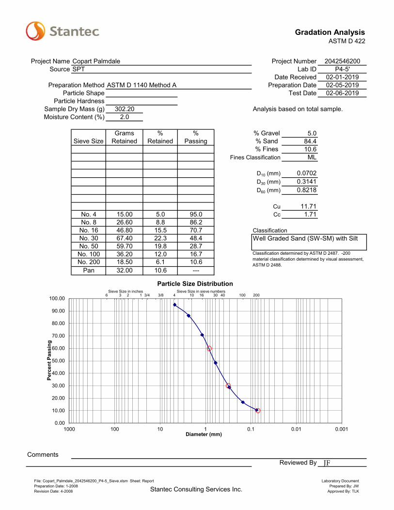
Gradation AnalysisASTM D 422
Project Name Copart Palmdale Project Number 2042546200Source SPT Lab ID P4-5'
Date Received 02-01-2019Preparation Method ASTM D 1140 Method A Preparation Date 02-05-2019
Particle Shape Test Date 02-06-2019Particle Hardness
Sample Dry Mass (g) 302.20 Analysis based on total sample.Moisture Content (%) 2.0
Grams % % % Gravel 5.0Sieve Size Retained Retained Passing % Sand 84.4
% Fines 10.6Fines Classification ML
D10 (mm) 0.0702D30 (mm) 0.3141D60 (mm) 0.8218
Cu 11.71No. 4 15.00 5.0 95.0 Cc 1.71No. 8 26.60 8.8 86.2No. 16 46.80 15.5 70.7 ClassificationNo. 30 67.40 22.3 48.4No. 50 59.70 19.8 28.7No. 100 36.20 12.0 16.7No. 200 18.50 6.1 10.6
Pan 32.00 10.6 ---
CommentsReviewed By
Well Graded Sand (SW-SM) with Silt
Classification determined by ASTM D 2487. -200 material classification determined by visual assessment, ASTM D 2488.
6 3 2 1 3/4 3/8 4 10 16 30 40 100 200
0.00
10.00
20.00
30.00
40.00
50.00
60.00
70.00
80.00
90.00
100.00
0.0010.010.11101001000
Perc
ent P
assi
ng
Diameter (mm)
Particle Size DistributionSieve Size in inches Sieve Size in sieve numbers
File: Copart_Palmdale_2042546200_P4-5_Sieve.xlsm Sheet: ReportPreparation Date: 1-2008Revision Date: 4-2008 Stantec Consulting Services Inc.
Laboratory DocumentPrepared By: JW
Approved By: TLK
JF

Compaction Characteristics of SoilUsing Modified Effort
ASTM D 1557 - Method B
Project Copart Palmdale Project No. 2042546200Source Bulk Bag (0-5') Sample ID B1-Bulk
Description Silty-Sand F-C (SM) Brown Date Received 02/01/2019Visual Notes Date Tested 02/04/2019
Test Fraction (%) 0.0 Oversized Fraction (%) 0.0Gs of Test Fraction 2.7 Estimated Gs of Oversized Fraction 0.0 ASTM C 127
Oversized Fraction Sieve 3/4" MC of Oversized Fraction (%) 0.0
Mold Weight (g) 4254.8 Preparation Method Moist Rammer Type Manual
Wet Soil Dry& Mold Wet Soil Wet Soil Dry Soil Water Unit Weight
Weight (g) Weight (g) & Tare (g) & Tare (g) Tare (g) Content (%) (pcf)6178 1923 522.70 499.70 0.00 4.6 121.46251 1996 506.60 475.70 0.00 6.5 123.76305 2050 513.80 473.10 0.00 8.6 124.66296 2041 504.60 455.80 0.00 10.7 121.7
Maximun Dry Unit Weight (pcf) 124.7Optimum Moisture Content (%) 8.2
Corrected Maximun Dry Unit Weight (pcf) N/ACorrected Optimum Moisture Content (%) N/A
Comments
Moisture Content Determination
118
119
120
121
122
123
124
125
126
127
128
2 4 6 8 10 12 14
Dry
Uni
t Wei
ght (
pcf)
Moisture Content (%)
Zero Air VoidsGs = 2.7
File: Copart_Palmdale_2042546200_Bulk1_Max.xlsm Sheet: ReportPreparation Date: 4-2010Revision Date: N/A Stantec Consulting Services Inc.
Laboratory DacumentPrepared By: JW
Approved By: TLK
Reviewed By: JF

Compaction Characteristics of SoilUsing Modified Effort
ASTM D 1557 - Method B
Project Copart Palmdale Project No. 2042546200Source Bulk Bag (0-5') Sample ID B12-Bulk
Description Silty-Sand F-C (SM) Red-Brown Date Received 02/01/2019Visual Notes Date Tested 02/04/2019
Test Fraction (%) 0.0 Oversized Fraction (%) 0.0Gs of Test Fraction 2.7 Estimated Gs of Oversized Fraction 0.0 ASTM C 127
Oversized Fraction Sieve 3/4" MC of Oversized Fraction (%) 0.0
Mold Weight (g) 4254.8 Preparation Method Moist Rammer Type Manual
Wet Soil Dry& Mold Wet Soil Wet Soil Dry Soil Water Unit Weight
Weight (g) Weight (g) & Tare (g) & Tare (g) Tare (g) Content (%) (pcf)6237 1982 488.60 460.70 0.00 6.1 123.46314 2059 513.10 474.20 0.00 8.2 125.66360 2105 504.80 457.70 0.00 10.3 126.06332 2077 516.40 460.70 0.00 12.1 122.3
Maximun Dry Unit Weight (pcf) 126.2Optimum Moisture Content (%) 9.7
Corrected Maximun Dry Unit Weight (pcf) N/ACorrected Optimum Moisture Content (%) N/A
Comments
Moisture Content Determination
119
120
121
122
123
124
125
126
127
128
129
3 5 7 9 11 13 15
Dry
Uni
t Wei
ght (
pcf)
Moisture Content (%)
Zero Air VoidsGs = 2.7
File: Copart_Palmdale_2042546200_Bulk12_Max.xlsm Sheet: ReportPreparation Date: 4-2010Revision Date: N/A Stantec Consulting Services Inc.
Laboratory DacumentPrepared By: JW
Approved By: TLK
Reviewed By: JF
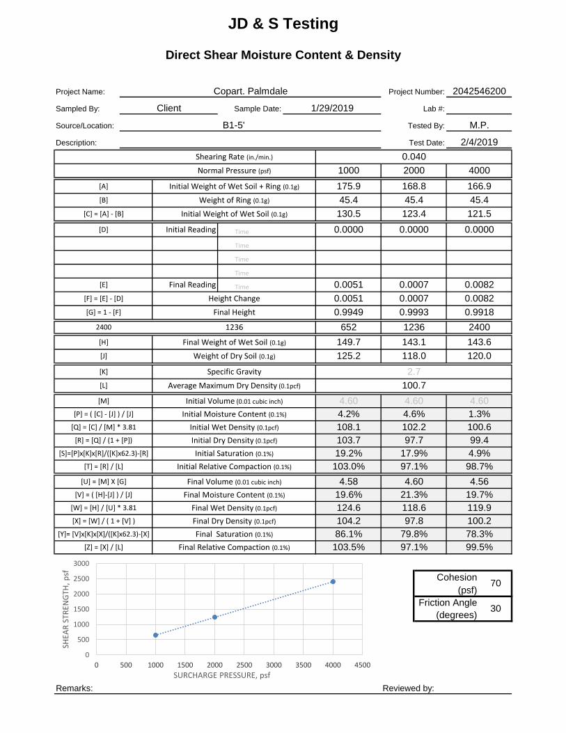
Time
Time
Time
Time
Time
1000 652 Cohesion2000 1236 (psf)4000 2400 Friction Angle
(degrees)
Remarks: Reviewed by:
149.7
30
70
Specific Gravity
Initial Volume (0.01 cubic inch)
Description:
0.0000 0.0000 0.0000
0.9949 0.9993 0.9918
[S]=[P]x[K]x[R]/([K]x62.3)-[R]
[K]
JD & S Testing
Direct Shear Moisture Content & Density
Source/Location: B1-5'
Project Name:
Sampled By:
Project Number:
Lab #:
M.P.
Sample Date:
2/4/2019Test Date:
Tested By:
Client 1/29/2019
[T] = [R] / [L]
[V] = ( [H]-[J] ) / [J]
175.9
45.4 45.4 45.4
130.5 123.4 121.5
[R] = [Q] / (1 + [P])
0.040Shearing Rate (in./min.)
1236 1236 2400
Initial Reading
Final Reading
166.9168.8
125.2 118.0 120.0
2042546200Copart. Palmdale
143.1 143.6
1000
[E]
[F] = [E] - [D]
[G] = 1 - [F]
[H]
Normal Pressure (psf)
2400
Height Change
2000 4000
652
0.0051 0.0007 0.0082
0.0051 0.0007 0.0082
103.5% 97.1% 99.5%
19.6% 21.3% 19.7%124.6 118.6 119.9
97.8 100.2
4.60 4.60 4.60
Average Maximum Dry Density (0.1pcf)
Initial Relative Compaction (0.1%)
86.1% 79.8% 78.3%
1.3%108.1 102.2 100.6103.7 97.7 99.4
4.2% 4.6%
2.7
100.7
104.2
4.60 4.564.58
19.2% 17.9% 4.9%103.0% 97.1% 98.7%
[Y]= [V]x[K]x[X]/([K]x62.3)-[X]
[Z] = [X] / [L]
Initial Weight of Wet Soil + Ring (0.1g)
Weight of Ring (0.1g)
Initial Weight of Wet Soil (0.1g)
[M]
[U] = [M] X [G]
Final Moisture Content (0.1%)
Final Wet Density (0.1pcf)
Final Dry Density (0.1pcf)
Initial Moisture Content (0.1%)
Initial Wet Density (0.1pcf)
Initial Dry Density (0.1pcf)
Initial Saturation (0.1%)
Final Saturation (0.1%)
Final Volume (0.01 cubic inch)
[W] = [H] / [U] * 3.81
[X] = [W] / ( 1 + [V] )
Final Relative Compaction (0.1%)
[L]
[A]
[B]
Final Height
Final Weight of Wet Soil (0.1g)
Weight of Dry Soil (0.1g)
[C] = [A] - [B]
[D]
[Q] = [C] / [M] * 3.81
[P] = ( [C] - [J] ) / [J]
[J]
0
500
1000
1500
2000
2500
3000
0 500 1000 1500 2000 2500 3000 3500 4000 4500
SHEA
R S
TREN
GTH
, p
sf
SURCHARGE PRESSURE, psf

Time
Time
Time
Time
Time
1000 648 Cohesion2000 1200 (psf)4000 2424 Friction Angle
(degrees)
Remarks: Reviewed by:
Final Height
Final Weight of Wet Soil (0.1g)
Weight of Dry Soil (0.1g)
[C] = [A] - [B]
[D]
[Q] = [C] / [M] * 3.81
[P] = ( [C] - [J] ) / [J]
[J]
[Y]= [V]x[K]x[X]/([K]x62.3)-[X]
[Z] = [X] / [L]
Initial Weight of Wet Soil + Ring (0.1g)
Weight of Ring (0.1g)
Initial Weight of Wet Soil (0.1g)
[M]
[U] = [M] X [G]
Final Moisture Content (0.1%)
Final Wet Density (0.1pcf)
Final Dry Density (0.1pcf)
Initial Moisture Content (0.1%)
Initial Wet Density (0.1pcf)
Initial Dry Density (0.1pcf)
Initial Saturation (0.1%)
Final Saturation (0.1%)
Final Volume (0.01 cubic inch)
[W] = [H] / [U] * 3.81
[X] = [W] / ( 1 + [V] )
Final Relative Compaction (0.1%)
[L]
[A]
[B]
4.57 4.524.58
30.3% 25.9% 33.2%103.9% 97.4% 97.5%
4.60 4.60 4.60
Average Maximum Dry Density (0.1pcf)
Initial Relative Compaction (0.1%)
86.5% 80.4% 93.4%
9.1%106.6 99.9 101.799.4 93.2 93.3
7.2% 7.2%
2.7
95.7
99.8
104.3% 98.2% 99.2%
22.0% 23.6% 26.7%121.7 116.0 120.2
93.9 94.9
2000 4000
648
0.0036 0.0076 0.0169
0.0036 0.0076 0.0169
2042546200C0part. Palmdale
139.0 142.7
1000
[E]
[F] = [E] - [D]
[G] = 1 - [F]
[H]
Normal Pressure (psf)
Height Change
[R] = [Q] / (1 + [P])
0.040Shearing Rate (in./min.)
Shear Strength (psf) 1200 2424
Initial Reading
Final Reading
168.0166.3
120.0 112.5 112.6
Lab #:
M.P.
Sample Date:
2/4/2019Test Date:
Tested By:
Client 1/29/2019
[T] = [R] / [L]
[V] = ( [H]-[J] ) / [J]
174.5
45.8 45.7 45.2
128.7 120.6 122.8
JD & S Testing
Direct Shear Moisture Content & Density
Source/Location: B2-7'
Project Name:
Sampled By:
Project Number:
146.4
31
40
Specific Gravity
Initial Volume (0.01 cubic inch)
Description:
0.0000 0.0000 0.0000
0.9964 0.9924 0.9831
[S]=[P]x[K]x[R]/([K]x62.3)-[R]
[K]
0
500
1000
1500
2000
2500
3000
0 500 1000 1500 2000 2500 3000 3500 4000 4500
SHEA
R S
TREN
GTH
, p
sf
SURCHARGE PRESSURE, psf
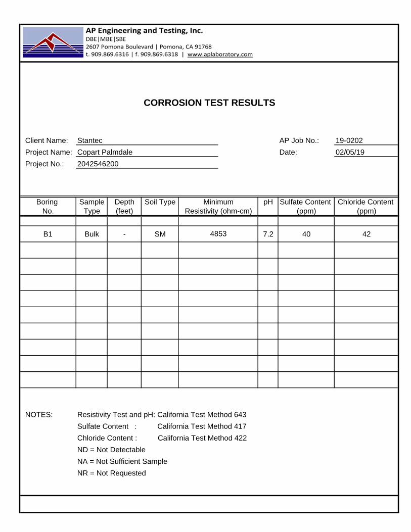
CORROSION TEST RESULTS
Client Name: Stantec AP Job No.: 19-0202
Project Name: Copart Palmdale Date: 02/05/19
Project No.: 2042546200
Boring Sample Depth Soil Type pH Sulfate Content Chloride Content No. Type (feet) (ppm) (ppm)
B1 Bulk - SM 7.2 40 42
NOTES: Resistivity Test and pH: California Test Method 643
Sulfate Content : California Test Method 417
Chloride Content : California Test Method 422
ND = Not Detectable
NA = Not Sufficient Sample
NR = Not Requested
MinimumResistivity (ohm-cm)
4853

Project Name: Copart PalmdaleProject Number: 2042546200Boring No.: B6Sample Type: Bulk Depth (ft.): -Location: N/ASoil Description: Clayey Sand
Mold Number G H IWater Added, g 68 52 43Compact Moisture(%) 12.8 11.1 10.2Compaction Gage Pressure, psi 150 250 350Exudation Pressure, psi 180 419 680Sample Height, Inches 2.5 2.5 2.5Gross Weight Mold, g 2927 2932 2899Tare Weight Mold, g 1827 1836 1818Net Sample Weight, g 1100 1095 1081
Expansion, inchesx10-4 4 29 64Stability 2,000 (160 psi) 61/129 43/92 21/39Turns Displacement 4.38 4.07 3.82R-Value Uncorrected 12 31 67R-Value Corrected 12 31 67Dry Density, pcf 118.2 119.4 118.8Traffic Index 8.0 8.0 8.0G.E. by Stability 1.68 1.31 0.63G.E. by Expansion 0.01 0.10 0.21
Date:
02/04/19
02/08/19Checked By:
STKMAP
R-VALUE TEST DATAASTM D2844
Tested By:Computed By: 02/06/19
Date:Date:
Gf = 1.34, and 0.0 % Retained on the ¾"
*Not ApplicableRem
arks
By Exudation:
By Expansion:
At Equilibrium:
(by Exudation)
R-V
ALU
E
21
*N/A
21
0
10
20
30
40
50
60
70
80
90
100
0100200300400500600700800
R-V
ALU
E
EXUDATION PRESSURE - PSI
0.00
1.00
2.00
3.00
4.00
0.00 1.00 2.00 3.00 4.00
CO
VE
R T
HIC
KN
ES
S B
Y S
TA
BIL
OM
ET
ER
(F
T.)
COVER THICKNESS BY EXPANSION (FT.)

APPENDIX C PERCOLATION TEST RESULTS

Project: Project No. Date: 1/29/2019Test Hole No. Tested By:
72 USCS Soil Classification
Length Width
Diameter (if round) 8 Sides (if rectangular)
Trial No. Start Time Stop TimeTime Interval,
(min)
Initial Depth of
Water (in)
Final Depth of
Water (in)
Change in Water
Level (in.)
Greater than or Equal to 6"? (y/n)
1 9:10 9:40 30 28.9 11.4 17.4 y
2 9:40 10:10 30 31.5 11.4 20.1 y
Trial No. Start Time Stop TimeΔt, Time
Interval, (min)
Do, Initial Depth of
Water (in)
Df, Final Depth of
Water (in)
ΔD, Change in
Water Level (in.)
Percolation Rate (in/hr)
1 10:53 11:03 10 45.0 22.25 22.8 136.52 11:03 11:13 10 40.3 24.125 16.1 96.83 11:13 11:23 10 42.0 24.75 17.3 103.54 11:23 11:33 10 41.5 24.875 16.6 99.85 11:33 11:43 10 40.8 24.25 16.5 99.06 11:43 11:53 10 39.3 23 16.3 97.5789
101112131415
Comments: Reduction Factor (Rf) = ((2d1 - delta d) / DIA) + 1 Rf = ((2*39.5)-16.3)/8)+1d1 = initial water depth (inches) Rf = 8.84delta d = water level drop of the stabilized rate (inches) Infiltration rate (Ir) = perc rate / Rf = 97.5/8.84DIA = diameter of the boring (inches) Ir = 11.0 inches/hour
Factor of Safety (FS) = 3.0 Irall = Ir / FS = 11 / 3.0 = 3.7 in/hr
Test Hole Dimensions (inches)
Sandy Soil Test Criteria*
*If two consecutive measurements show that twelve inches of water seeps away in less than 30 minutes, the test shall be run for an additional hour with measurements taken every 10 minutes. Otherwise, pre-soak (fill) for a minimum of four hours before running test. Obtain at least eight measurements per hole over at least four hours (approximately 30 minute intervals) with a precision of at least 1/8" until the last 3 consecutive readings are within 10% of each other.
PERCOLATION TEST DATA SHEET
Copart Palmdale 2042546200P1 JS
Depth of Test Hole, DT: SP

Project: Project No. Date: 1/29/2019Test Hole No. Tested By:
62.75 USCS Soil Classification
Length Width
Diameter (if round) 8 Sides (if rectangular)
Trial No. Start Time Stop TimeTime Interval,
(min)
Initial Depth of
Water (in)
Final Depth of
Water (in)
Change in Water
Level (in.)
Greater than or Equal to 6"? (y/n)
1 10:30am 11:00am 30 12.0 0.0 12.0 y
2 11:00am 11:40am 30 12.0 0.0 12.0 y
Trial No. Start Time Stop TimeΔt, Time
Interval, (min)
Do, Initial Depth of
Water (in)
Df, Final Depth of
Water (in)
ΔD, Change in
Water Level (in.)
Percolation Rate (in/hr)
1 12:10 12:20 10 30.8 0 30.8 184.52 12:20 12:30 10 34.4 0 34.4 206.33 12:30 12:40 10 36.3 0 36.3 217.54 12:40 12:50 10 35.3 0 35.3 211.55 12:50 13:00 10 35.8 0 35.8 214.56 13:00 13:10 10 35.9 0 35.9 215.3789
101112131415
Comments: Reduction Factor (Rf) = ((2d1 - delta d) / DIA) + 1 Rf = ((2*35.9)-35.9)/8)+1d1 = initial water depth (inches) Rf = 5.5delta d = water level drop of the stabilized rate (inches) Infiltration rate (Ir) = perc rate / Rf = 215/5.5DIA = diameter of the boring (inches) Ir = 39.3 inches/hour
Factor of Safety (FS) = 3.0 Irall = Ir / FS = 39.3 / 3.0 = 13.1 in/hr
Test Hole Dimensions (inches)
Sandy Soil Test Criteria*
*If two consecutive measurements show that twelve inches of water seeps away in less than 30 minutes, the test shall be run for an additional hour with measurements taken every 10 minutes. Otherwise, pre-soak (fill) for a minimum of four hours before running test. Obtain at least eight measurements per hole over at least four hours (approximately 30 minute intervals) with a precision of at least 1/8" until the last 3 consecutive readings are within 10% of each other.
PERCOLATION TEST DATA SHEET
Copart Palmdale 2042546200P2 JS
Depth of Test Hole, DT: SW-SM

Project: Project No. Date: 1/29/2019Test Hole No. Tested By:
72 USCS Soil Classification
Length Width
Diameter (if round) 8 Sides (if rectangular)
Trial No. Start Time Stop TimeTime Interval,
(min)
Initial Depth of
Water (in)
Final Depth of
Water (in)
Change in Water
Level (in.)
Greater than or Equal to 6"? (y/n)
1 9:10 9:40 30 47.0 62.6 15.6 y
2 9:40 10:10 30 46.0 62.6 16.6 y
Trial No. Start Time Stop TimeΔt, Time
Interval, (min)
Do, Initial Depth of
Water (in)
Df, Final Depth of
Water (in)
ΔD, Change in
Water Level (in.)
Percolation Rate (in/hr)
1 8:18 8:28 10 39.0 28.5 10.5 63.02 8:28 8:38 10 39.5 33.25 6.3 37.53 8:38 8:48 10 38.3 32 6.3 37.54 8:48 8:58 10 36.0 31.75 4.3 25.55 8:58 9:08 10 42.3 34 8.3 49.56 9:08 9:18 10 37.0 30.75 6.3 37.5789
101112131415
Comments: Reduction Factor (Rf) = ((2d1 - delta d) / DIA) + 1 Rf = ((2*37)-6.3)/8)+1d1 = initial water depth (inches) Rf = 9.46delta d = water level drop of the stabilized rate (inches) Infiltration rate (Ir) = perc rate / Rf = 37.5/9.5DIA = diameter of the boring (inches) Ir = 3.95 inches/hour
Factor of Safety (FS) = 3.0 Irall = Ir / FS = 3.95 / 3.0 = 1.3 in/hr
Test Hole Dimensions (inches)
Sandy Soil Test Criteria*
*If two consecutive measurements show that twelve inches of water seeps away in less than 30 minutes, the test shall be run for an additional hour with measurements taken every 10 minutes. Otherwise, pre-soak (fill) for a minimum of four hours before running test. Obtain at least eight measurements per hole over at least four hours (approximately 30 minute intervals) with a precision of at least 1/8" until the last 3 consecutive readings are within 10% of each other.
PERCOLATION TEST DATA SHEET
Copart Palmdale 2042546200P3 JS
Depth of Test Hole, DT: SP

Project: Project No. Date: 1/29/2019Test Hole No. Tested By:
62.75 USCS Soil Classification
Length Width
Diameter (if round) 8 Sides (if rectangular)
Trial No. Start Time Stop TimeTime Interval,
(min)
Initial Depth of
Water (in)
Final Depth of
Water (in)
Change in Water
Level (in.)
Greater than or Equal to 6"? (y/n)
1 8:00 8:30 30 12.0 0.0 12.0 y
2 8:30am 9:00am 30 12.0 0.0 12.0 y
Trial No. Start Time Stop TimeΔt, Time
Interval, (min)
Do, Initial Depth of
Water (in)
Df, Final Depth of
Water (in)
ΔD, Change in
Water Level (in.)
Percolation Rate (in/hr)
1 9:35 9:45 10 24.0 4 20.0 120.02 9:45 9:55 10 19.75 4.625 15.1 90.83 9:55 10:05 10 33.25 6 27.3 163.54 10:05 10:15 10 33.75 7.5 26.3 157.55 10:15 10:25 10 34.3 5.875 28.4 170.36 10:25 10:35 10 31.875 6.875 25.0 150.0789
101112131415
Comments: Reduction Factor (Rf) = ((2d1 - delta d) / DIA) + 1 Rf = ((2*31.9)-25)/8)+1d1 = initial water depth (inches) Rf = 5.84delta d = water level drop of the stabilized rate (inches) Infiltration rate (Ir) = perc rate / Rf = 150/5.84DIA = diameter of the boring (inches) Ir = 25.7 inches/hour
Factor of Safety (FS) = 3.0 Irall = Ir / FS = 25.7 / 3.0 = 8.6 in/hr
Test Hole Dimensions (inches)
Sandy Soil Test Criteria*
*If two consecutive measurements show that twelve inches of water seeps away in less than 30 minutes, the test shall be run for an additional hour with measurements taken every 10 minutes. Otherwise, pre-soak (fill) for a minimum of four hours before running test. Obtain at least eight measurements per hole over at least four hours (approximately 30 minute intervals) with a precision of at least 1/8" until the last 3 consecutive readings are within 10% of each other.
PERCOLATION TEST DATA SHEET
Copart Palmdale 2042546200P4 JS
Depth of Test Hole, DT: SW-SM


![APPENDIX F Geotechnical Investigation Report · Geotechnical Investigation Report!!!!! [Page left intentionally blank.] ... obtained from previous investigation, and slope stability](https://img.pdfslide.net/doc/110x75/5ed3369c20ca8951594598e3/appendix-f-geotechnical-investigation-report-geotechnical-investigation-report.jpg)