Embed Size (px)
Citation preview
APPENDIX FCULTURAL RESOURCES
GREENVILLE YARD, TRANSFER BRIDGE SYSTEM AND FREIGHT OPERATIONS City of Jersey City Hudson County New Jersey
WRITTEN HISTORICAL AND DESCRIPTIVE DATA
ARCHITECTURAL DRAWINGS
PHOTOGRAPHS
HISTORIC AMERICAN ENGINEERING RECORD New Jersey Historic Preservation Office
5 Station Plaza 501 East State Street
Trenton, New Jersey 08625
GREENVILLE YARD, TRANSFER BRIDGE SYSTEM AND FREIGHT OPERATIONS
(Page i)
HISTORIC AMERICAN ENGINEERING RECORD
GREENVILLE YARD, TRANSFER BRIDGE SYSTEM
AND FREIGHT OPERATIONS Location: Jersey City, Hudson County, New Jersey Date(s) of Construction: 1902-1904; Enlarged 1910 and 1924; Partially Destroyed by Fire
and Rebuilt 1931; Enlarged 1943; Repaired 1945; Partly Demolished 1996
Designer(s)/Engineer(s): William H. Brown, Chief Engineer; W. C. Bowles, Assistant
Engineer of Construction; L. H. Baker, Assistant Chief Engineer; F. L. Du Bosque, Assistant Engineer of Floating Equipment (machinery design)
Builder(s): New York Bay Railroad, a subsidiary of the Pennsylvania
Railroad Principal Contractor(s): Henry Steers Incorporated; Cooper-Wigand-Cook Company;
Steele & Condict; American Bridge Company Present Owner (s): New York New Jersey Rail L.L.C (a subsidiary of the Port
Authority of New York and New Jersey) by lease from Consolidated Rail Corporation (Conrail)
Present Use: Railroad Transportation Significance: Built under the auspices of the Pennsylvania Railroad between
1902 and 1904, and modified periodically throughout the twentieth century, the Greenville Yard Transfer Bridges are contributing resources to the National Register-eligible Greenville Yard Piers (DOE: 9/8/1981; SHPO Comments: 9/21/1983). The Greenville Yard Piers are eligible under Criterion A in the areas of engineering and transportation for their role in the development of the Port of New York and for their technological innovations in early freight handling operations. The Greenville Yard Piers (including the contributing Greenville Yard Transfer Bridges) are also key contributing resources to the National Register-eligible Greenville Yard Historic District (SHPO Opinion: 8/21/1998) and the Pennsylvania Railroad New York Bay Branch Historic District (SHPO Opinion: 4/22/2005).
Historian: Philip A. Hayden, Richard Grubb & Associates, Inc., July 2011
GREENVILLE YARD, TRANSFER BRIDGE SYSTEM AND FREIGHT OPERATIONS
(Page ii)
I. TABLE OF CONTENTS Data Sheet .............................................................................................................................................. i I. Table of Contents ................................................................................................................................. ii II. Project Information ............................................................................................................................. 1 III. Historical Information ......................................................................................................................... 3 The Port of New York and the Pennsylvania Railroad .................................................................... 3 Moving Freight ............................................................................................................................... 4 Harsimus Cove Yard and Early Transfer Bridge Prototypes ............................................................ 6 Initial Plans to Expand Freight Handling Facilities ....................................................................... 8 The New York Tunnel Extension Project ..................................................................................... 10 Greenville Terminal ...................................................................................................................... 12 Greenville Transfer Bridges ........................................................................................................... 13 Greenville Yard Freight Operations .............................................................................................. 14 From Penn Central to New York-New Jersey Rail ....................................................................... 18 IV. Architectural Information ................................................................................................................. 21 V. Sources of Information ..................................................................................................................... 23 VI. Attachments ........................................................................................................................................ 31 A. Figures ........................................................................................................................................ X B. Supplemental Material .............................................................................................................. X C. Photo Recordation .................................................................................................................... X
GREENVILLE YARD, TRANSFER BRIDGE SYSTEM AND FREIGHT OPERATIONS
(Page 1)
II. PROJECT INFORMATION The Port Authority of New York and New Jersey (PANYNJ), acting as co-lead agency with the Federal Highway Administration (FHWA) and using funds provided through the FHWA, is acquiring Greenville Yard in Jersey City, Hudson County, New Jersey and procuring the replacement of the Greenville Yard Transfer Bridges and associated infrastructure. Known as the Greenville Yard Lift [Transfer] Bridge Acquisition and Replacement Project, the undertaking is part of the Cross Harbor Freight Program, an initiative designed to improve regional goods movement. As part of these efforts, in 2008, PANYNJ acquired New York New Jersey Rail, LLC (NYNJR), which leases and operates a rail car float between Greenville Yard and Bush Terminal Yard in Brooklyn, New York from the Consolidated Rail Corporation (Conrail). This Historic American Engineering Record (HAER) recordation document has been prepared in partial fulfillment of Stipulation IA of a Memorandum of Agreement (MOA) dated March 17, 2011 among the FHWA, the PANYNJ, and the New Jersey Historic Preservation Officer (SHPO) regarding the Greenville Yard Lift [Transfer] Bridge Acquisition and Replacement Project. The history, technical specifications, and significance of the Greenville Yard Piers, Transfer Bridges, and Greenville Yard Historic District were recorded in previous HAER documentation (HAER 1983; 1996). The present recordation supplements these prior studies with additional details and aims to contextualize the engineering of the Greenville Yard Transfer Bridges by comparing it with the design of other transfer bridge structures in the historical record and by discussing the Greenville Yard Transfer Bridges within the framework of the larger Pennsylvania Railroad (PRR) freight network. Greenville Yard extends approximately 1.7 miles into New York Harbor on made land. At the western extreme, the yard throat crosses over the former Central Railroad of New Jersey (CRRNJ) right-of-way (present day NJ TRANSIT Hudson-Bergen Light Rail) on a two-span, double track through plate girder bridge. A second parallel bridge carrying the former Lehigh Valley Railroad (LVRR) right-of-way (present-day Conrail National Docks Secondary) shares the same substructure. Much of the former yard property has been sold and developed. Remaining railroad operations include a receiving and interchange yard, an auto yard, and a processing plant for Tropicana, all served by Conrail. Two private carriers interchange with Conrail at this point. The Port Jersey Railroad serves several businesses. The PANYNJ, through its NYNJR subsidiary, operates Greenville Yard and the transfer bridge operations. The Greenville Yard Piers (a.k.a. Greenville Yard Transfer Bridge System) received a SHPO Opinion of Eligibility on July 27, 1978, and the Keeper of the National Register of Historic Places (Keeper) subsequently concurred with a Determination of Eligibility (DOE) on September 8, 1981. The Greenville Yard Piers eligibility was affirmed and further elaborated on in SHPO consultation comments dated September 21, 1983 in connection with the United States Army Corps of Engineer’s proposed removal of several contributing structures. The Greenville Yard Piers are eligible under Criterion A in the areas of engineering and transportation for its role in the development of the Port of New York and for its technological innovations in early freight handling operations. At the time of the SHPO Opinion, the historic property included five contributing resources: the transfer bridge structure comprising six bays (or slips); a long open pier with four gantry cranes; a shorter covered pier; a coal loading hopper; and an ice jetty.
GREENVILLE YARD, TRANSFER BRIDGE SYSTEM AND FREIGHT OPERATIONS
(Page 2)
In information submitted to the Keeper as part of the request for the DOE, the recommended property boundaries included the intact waterfront and pier structures. The main yard area to the west of the shoreline was deliberately omitted because it lacked integrity. The period of significance was identified only as the “early twentieth century.” The SHPO subsequently identified two additional contributing resources: Car Float Barge #16 and Car Float Barge #29 (SHPO Opinion: 9/15/2010 [Log # 10-1370-5]). Consequently, the period of significance of the Greenville Yard Piers was revised to 1960 to include both car float barges. The Greenville Yard Piers are also key contributing resources to the National Register-eligible Greenville Yard Historic District (SHPO Opinion: 8/21/1998) and the PRR New York Bay Branch Historic District (SHPO Opinion: 4/22/2005). Of the original contributing resources comprising Greenville Yard Piers, only portions of the transfer bridges and the remains of two piers are standing. The other resources have been demolished.
GREENVILLE YARD, TRANSFER BRIDGE SYSTEM AND FREIGHT OPERATIONS
(Page 3)
III. HISTORICAL INFORMATION In summary, the Greenville Yard transfer bridge system is the last surviving example of the non-pontoon, double-gantry suspension and counterweight-type transfer bridge and car float operation in New York Harbor. Developed initially in the 1880s by engineers in the PRR’s Jersey City offices for application at the company’s Harsimus Cove Yard in Jersey City, the bridge technology was refined and electrified in conjunction with the opening of Greenville Yard in 1904-1905. The transfer bridge design, incorporating movable bridges, aprons, and counterweights, along with an electrically powered screw lift mechanism, formed the basic design elements employed in nearly every later transfer bridge type used by other railroads (HAER 1996). The Port of New York and the Pennsylvania Railroad Accessing the Port of New York in general, and Manhattan in particular, presented serious obstacles to railroad builders approaching from the west. They faced a gauntlet of physical and political barriers (New York, New Jersey Port and Harbor Commission 1920: 62). Overcoming rivers, swamps, and hills of solid rock, not to mention scarce water frontage and the harbor, required skilled engineering, large amounts of capital, and boats. New Jersey’s first railroad, the Camden and Amboy Railroad (C&ARR), elected to build its terminal at South Amboy and ferry passengers and freight the remaining distance to Manhattan. The New Jersey Railroad (NJRR), chartered in 1832, was the first to reach the Jersey City riverfront in 1838. Its greatest obstacle, a ridge of hard rock called Bergen Hill, separated the west side of the North (Hudson) River from the interior. The NJRR succeeded in excavating a 40-foot deep channel through the hill called the Bergen Cut and used it to run trains between New Brunswick, New Jersey and the harbor’s edge (Burgess and Kennedy 1949: 255; Messer and Roberts 2002: 117). With its terminal located directly across the river from lower Manhattan, the NJRR provided quick communication between the two river banks, and it became the route of choice for moving railroad passengers and freight to and from the city. The Bergen Cut remained the only practical rail route through the Bergen Hill for over 20 years, and other railroads soon vied for access (Burgess and Kennedy 1949: 257; Cunningham 1997: 60). In conjunction with the NJRR, the C&ARR formed the first all-rail route between the Port of New York and Philadelphia and funneled most of its passenger traffic through to Jersey City. However, the C&ARR continued to send its lucrative freight business through its own terminal at South Amboy terminal, thereby keeping the profits (Messer and Roberts 2002: 17). The Paterson & Hudson River Railroad (P&HRRR), chartered in 1831 to bring rail service from Paterson to Jersey City, accessed the riverfront via the Bergen Cut in 1838 (Messer and Roberts 2002: 115). In 1852, the larger New York & Erie Railroad (NY&ERR), in search of its own route to the Port of New York, leased the P&HRRR and formed the first direct all-rail trunk line between the Great Lakes and New York Harbor by way of the Bergen Cut (Hungerford 1946: 132-133). The Morris & Essex Railroad (M&ERR) made its own connection with the NJRR in Newark in 1853, and sent its trains by way of the NJRR tracks into Jersey City (Taber 1977: 50). Eventually, the PRR achieved its own long-sought-after outlet to the Hudson River via the Bergen Cut, first by way of agreement with the C&ARR and the NJRR, and later in 1871 by means of a 999-year lease of their successor company, the United New Jersey Railroad & Canal Company (UNJRR&C Co) (Burgess and Kennedy 1949: 240).
GREENVILLE YARD, TRANSFER BRIDGE SYSTEM AND FREIGHT OPERATIONS
(Page 4)
Moving Freight The PRR, with its lease of the UNJRR&C Co, worked aggressively to expand harbor facilities for both passenger and freight operations (Droege 1916; Burgess and Kennedy 1949; Condit 1980; Messer and Roberts 2002). Except for the New York Central Railroad (NYCRR) system, which controlled the only direct all-rail link into Manhattan, all other railroads entering the port confronted an established marine system for accessing Manhattan. This system, in place since initial European settlement, relied entirely on boats and other floating vessels and proved both efficient and cost-effective. With the opening of the Erie Canal and the Morris Canal, deliveries of long haul cargo by barge to points anywhere around the port became possible without breaking bulk (Flagg 1994: 6). With this infrastructure in place, railroads developed comparable facilities using ferries, barges, and car floats, and the tidewater terminal became the standard for all major trunk lines operating in the Port of New York (Flagg 1994: 6). Early rail-marine freight was usually transported on the same ferries as passengers. By the 1860s, many railroads delegated their freight delivery services to lighter operators, who moved barges of goods between transfer points and to the holds of ships at anchor. The lighterage system, while flexible and convenient, added costs to the land-locked railroads, which had to compete with canals serving the Port of New York. Railroads could earn enough money from their long haul freight operations to subsidize the cost of the lighterage delivery charges at the end of the line. But shorter hauls meant less revenue to the railroads and smaller subsidies to support the free lighterage system. Despite these drawbacks, the railroads continued the practice of free lighterage service long after the canals ended operations in order to compete for bulk shipments from consigners and this helped to perpetuate the rail-marine operations around New York Harbor (Flagg 1994: 7). While lighters served to handle the loading and unloading of freight from ships, car floats allowed railroads to deliver whole cars of freight to and from wharves and waiting ships (Flagg 1994: 8). This avoided the cost of extra handling between cars, barges, and lighters. As coordination between shippers, lighterage operators, and railroads matured, freight handling evolved into a carefully coordinated system by which car floats with loaded cars were moved every day around the harbor to the appropriate railroad terminals for transfer and connection with scheduled freight trains departing to points all around the country (Flagg 1994: 8). To move rail cars from land to vessels on the water, engineers modified the existing system of adjustable ramps employed for accommodating other wheeled vehicles on ferries. Conventional thought suggests that the first transfer bridges and accompanying car floats in the United States appeared with the operations of the Philadelphia, Wilmington & Baltimore Railroad at its Susquehanna River crossing at Harve De Grace and Perryville, Maryland in the 1850s (Roberts & Messer 2003: 38; 111). By adding rails to the boats, the operators could move entire trains by ferry using a pontoon bridge to effect the transfer. Other evidence suggests that John Henry Starin (1825-1909) perfected the system of freight car floats used in New York Harbor. The Starin City River & Harbor Transportation Company controlled lighterage and freight handling for many of the city’s major trunk railroads. Starin’s obituary credited him with “the idea of transporting freight cars on floats, and [he] was always very proud of this achievement” (New York Times 1909). Ultimately, transfer bridges included two basic types: the floating pontoon-style and the suspended gantry type. Pontoon transfer bridges relied on buoyant tanks to float one end of a hinged bridge on
GREENVILLE YARD, TRANSFER BRIDGE SYSTEM AND FREIGHT OPERATIONS
(Page 5)
the water’s surface. This system adjusted automatically with the tides, but fluctuated in the loading and unloading process and sometimes required additional vertical adjustments provided by heavy chains and by overhead or side gantries. The bridge was often subjected to heavy diagonal strains as engines were run along one side to bring the corner of the lighter bridge down to the level of the corresponding heavily loaded car float. Once the corners of the bridge and the car float were joined together with heavy iron toggle bars, the engine was run off again, causing the bridge and barge to torque. The procedure was then repeated on the other side of the bridge with similar results. The process took time and usually ended in high maintenance costs (Engineering News 1890: 67). Pontoon bridges were also prone to sinking if the tanks were drained of air, and they faced interference from silting action and the movement of heavy seas. Accumulations of frozen water on the pontoons and ice floes also proved a major problem, especially in the upper reaches of the Hudson River where ice was particularly prevalent. The gantry or gallows system relied on an overhead framework from which to suspend the end of a counterbalanced bridge above the water. This system allowed the bridge to rise and descend independently of the water level. It permitted more flexible adjustments to the height of the bridge during car movements and it eliminated the problem of interference from shallow waters or ice floes. Many gantry-style transfer bridges also utilized a separate apron at the water end of the bridge (Snow 1901: 161). The apron, a light platform, was hinged at one end to the main bridge and suspended by chains or cables at the other end to form a transition point between the main bridge and the car float. The apron provided transfer bridges with three points of vertical articulation: between the bulkhead and the bridge, the bridge and the apron, and the apron and the car float. This allowed for smoother operations and faster transfers of cars. But in both types of transfer bridges, the nature of the structures imposed serious engineering challenges. The rigid connection at the shore and the loose connection to the free-floating car float meant that all bridges faced serious damage from rough handling of the barge and high seas. Dynamic strains and wrenching meant that the structures required a measure of flexibility and could not be overly reinforced (Snow 1901: 164). The corresponding car floats were nothing more than wooden barges with rails. They came in a variety of configurations depending on the application. The first wooden car floats generally measured 240 feet in length (Brouwer 1990: 143). Some contained covered platforms in the center, which allowed handlers to sort freight or move it from cars to the bulkhead doors of ships while afloat. Many car floats contained two tracks, but three-track car floats gradually became the norm (Brouwer 1990: 144). The third track meant that a string of cars could be loaded onto the center of the float with a minimum of disruption to the barge’s center of gravity, and this improved its overall stability. Later, steel hull construction for car floats would begin to replace timber hull floats at the beginning of the twentieth century. Car floats required extra strength as their lengths increased to accommodate larger rolling stock and demands for greater capacity (Flagg 1997: 9). The rising cost of suitable timber also encouraged a shift toward riveted and welded steel floats. Moreover, their maintenance proved less costly than wood. The shift to all steel barges would be delayed by World War II, but by the late 1940s steel car floats became the general rule (Flagg 1997: 9). Transfer bridges were a necessary part of every trunk line terminal delivering freight to destinations around the harbor or interchanging cars with other railroads for destinations elsewhere. But not all transfer bridge facilities in the Port area were connected to outside rail lines. Some only received and delivered cars at manufacturing establishments or conventional freight warehouses (Flagg 1994: 9).
GREENVILLE YARD, TRANSFER BRIDGE SYSTEM AND FREIGHT OPERATIONS
(Page 6)
The PRR operated such facilities in Brooklyn (Flagg 1994: 9). More significant terminals, called contract terminals, comprised large freight handling operations under contract with the railroad freight lines. They agreed to handle terminal freight for the railroads in exchange for a share of the revenue (Flagg 1994: 9). The four main contract terminals were located in Brooklyn and included: New York Dock Company; Bush Terminal; Jay Street Connecting Railroad; and the Brooklyn Eastern District Terminal railroads (Flagg 1994: 9). The contract terminals typically operated their own barges, tugs, and car floats. They also had their own sorting yards and served a wide range of customers, including steam ship piers, warehouses, private sidings, freight houses, and team tracks (Flagg 1994: 9). Most waterfront freight deliveries, however, were made by negotiating a car float up to a pier or riverfront bulkhead from which freight could be loaded and unloaded directly from cars to the adjoining business using movable ramps and hand trucks (Flagg 1994: 9). Marine delivery became so central to railroad freight operations that the trunk lines began to assemble their own marine operations. The PRR became one of the first to acquire a fleet when it bought out the National Storage Company in 1879. The latter had been handling the PRR’s lighterage trade until that point (Flagg 1994: 7). By 1895, the PRR maintained 18 tug boats, 45 barges, and 65 car floats in New York Harbor (Scientific American 1895: 16587). By the end of the nineteenth century, moving freight around the Port of New York relied on the transfer bridge and car float system. Writing about the virtues of the car float system, a writer for Scientific American described its adaptability to the conditions of the port:
The capacity and flexibility of this method of handling freight, the cheapness with which it is done, the ease with which cars can be delivered to any point on the waterfront, the unlimited development of which the system is capable, are all elements which conspire to make any bridge across the North [Hudson] River or any tunnel underneath that river a superfluity, so far as handling freight may go (Scientific American 1895: 16587).
Harsimus Cove Yard and Early Transfer Bridge Prototypes In the years leading up to the PRR’s final lease of the lines leading into Jersey City, the railroad maintained reciprocal traffic agreements with the various participating railroads to carry each other’s traffic. The advantages of the arrangement were clearly spelled out in the press. “Passengers and freight,” noted the New York Times, “may be transported from the West by a route so direct as to present advantages to travelers and shippers, equal to those offered by the lines which have hitherto monopolized the trade” (New York Times 1869b: 3). The NJRR agreed to rebuild its outdated and ill-equipped terminal facilities at Jersey City in order to accommodate the anticipated traffic. To accomplish the job, it planned to utilize Harsimus Cove, a shallow-water bay adjoining the northern side of the railroad’s existing terminal. As early as 1856, the NJRR had been working to secure a stake in this valuable water frontage as a means to expand its terminal facilities and keep out competitors (The Atlantic Reporter 1887: 587). In order to extinguish all claims of the state to the riparian lands and to perfect the title to Harsimus Cove, as well as to obtain authority to build a branch line to the proposed terminal, the newly formed UNJRR&C Co. obtained an official act of the legislature, known at the time as the Harsimus Cove Bill (New Jersey Legislature 1868; New York Times 1868a: 5; 1868b: 1). The final bill passed on March 30, 1868 (New Jersey Legislature 1868: 551). The day after the consummation of the
GREENVILLE YARD, TRANSFER BRIDGE SYSTEM AND FREIGHT OPERATIONS
(Page 7)
Harsimus Cove purchase from the state on January 4, 1869, the New York Times offered the first glimpse of plans for the improvements to the site:
After filling in the land it is designed by the joint Railroad Companies before enumerated to construct an elevated air line railroad, a mile and a half long from the iron bridge that crosses the old Bergen Road to the water front, where huge depots and machine shops will be built, and whence a ferry will communicate with New-York. The road will be carried over the houses in Jersey City, and in some parts will be built on piles fifty feet deep. It will take as much as five years to complete it, and will cost fully $5,000,000 (New York Times 1869a:5).
The work of filling in the Harsimus Cove and building the branch line began under the corporate auspices of the NJRR in 1869, but the project was completed under the guidance of the PRR, following its lease of the UNJRR&C Co in 1871. The Harsimus Cove freight terminus—minus the connecting rail line—was finally placed into service on October 1, 1873 (Pennsylvania Railroad 1874:74). Within three months, the volume of western traffic handled by the PRR increased 60 percent (Pennsylvania Railroad 1874:74). Finally, in 1875, the PRR’s annual report noted that the “new railway [branch] to connect with the Harsimus Cove property has been opened for use through a portion of Bergen Hill from its connection with the Main Line” (Pennsylvania Railroad 1875: 46). The effect was immediate. Nearly 200 trains arrived and departed from Jersey City in any day, with over half passing to the freight facilities (Sipes 1875: 45). The yard, in addition to piers for handling ships, included a stock yard and abattoir, a grain elevator, a freight house, transfer bridges, and additional space for warehouses (Sipes 1875: 45). The first transfer bridges at Harsimus Cove went into service when the yard opened in 1873 (Mordecai 1885: 36; Bensel 1888: 310-311). A chronicler of the Port of New York described the structures as consisting of Howe truss bridges, 100 feet long, hinged at the shore end and suspended from a stationary frame by heavy iron chains near the river end. The chains ran over large sheave wheels mounted on the frame above and were worked by hand gears below to adjust to the height of the tide and the float. The description suggests that the bridges floated on pontoons, but no plans or other contemporary descriptions of the early float bridges at Harsimus Cove have been located. The operation included two-track timber car floats for handling Manhattan bound materials and goods. Three-track floats carried the New England-bound connecting traffic by way of the East River to interchange points on the Long Island Railroad (LIRR) at Long Island City and the New York, New Haven & Hartford Railroad (NYNH&HRR) at Port Morris on the Harlem River (Mordecai 1885: 36). Eastbound coal traffic was also transported to car floats 60 miles up-river to Fishkill-on-the-Hudson (Mordecai 1885: 36; Scientific American 1895: 16587). But the Harsimus Cove property posed special problems for the PRR owing to the shallowness of the water. Silting happened rapidly at the reclaimed land, so transfer bridges supported on floating pontoons easily bottomed out within a year or two of operation. Expensive disruptions and dredging operations resulted (Bensel 1888: 310). Beginning about May 1888, the PRR placed into operation at Harsimus Cove a pair of new transfer bridges (Figures 1 through 6) (Bensel 1888: 309). Changes in the design of this second generation of transfer bridges were subtle but significant. The new structure relied on a heavy timber gallows frame and counterweights to carry most of the dead load from the bridge. It also employed an
GREENVILLE YARD, TRANSFER BRIDGE SYSTEM AND FREIGHT OPERATIONS
(Page 8)
independently counterweighted apron controlled by a friction gear that held the apron stationary, but provided sufficient movement needed during the loading and unloading process (Bensel 1888: 310). The mechanism allowed for easy adjustments to any height of the float, which made the coupling process between the bridge and the car float both easy and quick and eliminated the need of running a locomotive onto the bridge. This reduced the warping caused by the old loading process and the related strains to the structure (Bensel 1888: 310; Engineering News 1890: 68). The chief advantage, however, was freeing the bridge of the pontoon and the corresponding interference from silt and ice in the harbor (Bensel 1888: 310). The new design also gave the bridge an adjustable range totaling over ten feet. Instead of chains to adjust the height of the bridge, the new mechanism used a vertical screw assembly threaded through a mount in the overhead timber gantry to carry the balance of the dead load and the live loads created by the cars. The screws were attached to the bridges by heavy iron linkages and moved up and down by means of a horizontal worm shaft in the gantry above, which meshed with a sprocketed bronze nut at the base of each screw that raised or lowered the screw when turned (Snow 1901: 165). At first the horizontal drive shaft was geared to a rod and capstan at the bridge deck level and operated by hand. By the end of 1888, however, the railroad switched to steam power using an engine on the platform between the two bridges (Bensel 1888: 310, 311; (Engineering News 1890: 68). With belts, the power was transferred from the engine to the horizontal shaft in the gantry above the bridge by way of a friction pulley that, when engaged, turned the shaft and raised or lowered the bridge automatically (Bensel 1888: 311). One man could operate the new bridge using a single lever from the control room. The screw lift mechanism was intended to compensate for changes in the tide and to make the minor adjustments needed during loading and unloading operations (Bensel 1888: 310). The apron, because of the counterbalance, could be raised and lowered by two men working on each side. The entire structure was enclosed in a single wooden shelter to protect the machinery and operating equipment and preserve the timber members from the elements. The new Harsimus Cove transfer bridges were designed in the Jersey City offices by the Pennsylvania Railroad Company and built using company men and materials (Bensel 1888: 311-312). They proved so successful that the railroad began erecting similar structures in Philadelphia (Bensel 1888: 309). One reporter described the new transfer bridges as altogether “the most scientific in design and convenient in operation of all those described” (Snow 1901: 165). Initial Plans to Expand Freight Handling Facilities By the mid-1880s, the PRR’s freight handling facilities were widely scattered about the Port of New York. Receiving yards and engine shops were located at Meadows Yard east of Newark. The western freight station, transfer bridges and piers, grain elevators, stock yards and abattoir were all located at Harsimus Cove. The main line freight station and the Red Line and Netherlands Steamship docks were adjacent to the PRR passenger station in Jersey City. Oil yards were located at Communipaw. Coal docks were at South Amboy. Within New York City, five separate locations handled freight (Mordecai 1885 29). The PRR also faced a shortage of freight capacity. To solve this problem, it began maneuvering quietly to gain control of additional water frontage along the shores of Bayonne, Greenville, and Pamrapo (New York Times 1887a: 1). Then on February 25, 1886, interests of the NYCRR, the PRR’s
GREENVILLE YARD, TRANSFER BRIDGE SYSTEM AND FREIGHT OPERATIONS
(Page 9)
arch-rival, incorporated the New Jersey Junction Railroad (NJJRR) (Transportation Corporation Files 1886; New Jersey Junction Railroad 1886). The goal of this short line was to build an eight-mile-long line between the NYCRR’s newly leased West Shore Railroad on the north side of the PRR’s terminal in Jersey City and the CRRNJ terminal on the south side. If built the NJJRR would give the NYCRR access to all the major shippers along the Hudson River, threatening the PRR’s business there (New York Times 1895: 8). The NJJRR could also give the NYCRR access to scarce water frontage toward Greenville, and potentially choke off the PRR’s own plans for expansion (New York Times 1889: 10). The PRR acted swiftly to block the NJJRR and stake out its own route to the undeveloped areas between Jersey City and Bayonne. Together with the affiliated National Docks Railway (NDR) the PRR filed a survey on September 3, 1886 to construct a connection between the NDR and the PRR’s Harsimus branch freight line (National Docks Railway 1886). Although the PRR and the NDR already possessed an interchange via the PRR’s old passenger main line near Waldo Avenue, that connection required freight and passenger trains to share the same tracks inside the Bergen Cut, and one of the company’s long-range goals in developing its New York port facilities involved separating the two types of traffic through this bottleneck. The planned connection between the Harsimus freight line and the NDR would duck beneath the PRR passenger tracks, adjacent to the proposed route of the NJJRR, thus allowing PRR freight trains to freely travel from Meadows Yard along the Harsimus freight line and beneath the PRR main line near Waldo Avenue to future terminal facilities planned for the lower Jersey City shoreline (Richard Grubb & Associates 2008: Form 3). Then in November 1887, Jersey City gave its final approval for the PRR to elevate its passenger tracks through that city as part of a large grade separation program (New York Times 1887b: 4). To accomplish this, the PRR would have to construct a large passenger car yard on new fill to be deposited next to the PRR’s passenger mainline, directly overtop the planned routes of both the NJJRR and the NDR (Messer and Roberts 2002: 196; New York Times 1887b: 4). This helped block the NJJRR, but it also forced the PRR to look for another way to run its freight trains to points south, and a little over a year later it announced plans to build a massive new freight terminal at Greenville. On February 8, 1889, the PRR chartered the Waverly & New York Bay Railroad Company to run from the main line near Waverly on the southwest side of Newark, across Newark Bay to the future yard at Greenville (Hayden 2008: 4). A second line, the Waverly & Passaic Railroad Company, was formed on February 11, 1889, to extend from the main line at Waverly to a new bridge across the Passaic River and on to a link with the Meadows Yard in Kearny (Transportation Corporation Files n.d.; Messer and Roberts 2002: 211). These two freight lines were consolidated on January 30, 1890, to form the New York Bay Railroad Company (NYBRR) (New York Bay Railroad Company: 1890.; Burgess and Kennedy 1949: 434). The combined routes promised to give access to proposed terminal facilities in the Greenville section of Jersey City and improve traffic flow into Meadows Yard and Harsimus Cove by diverting heavy freight traffic off the main line and around the congested bottleneck in downtown Newark (Messer and Roberts 2002: 211). The Greenville Branch of the newly combined railroads was completed between Waverly and a crossing with the CRRNJ in the middle of the Newark Meadows by September 1890 (Board of
GREENVILLE YARD, TRANSFER BRIDGE SYSTEM AND FREIGHT OPERATIONS
(Page 10)
Public Utility 1918). The Passaic Branch of the line was built between Waverly and Newark in 1892 (Board of Public Utility 1918; Messer and Roberts 2002: 228). Then construction stopped. An economic downturn dampened business activity in general, but the PRR also paused to contemplate grander schemes for handling traffic in New York. The New York Tunnel Extension Project For years the PRR had been considering the possibility of establishing direct rail communication to Manhattan, Long Island, and New England, thereby reducing ferry operations around the congested waters of New York Harbor. Early plans considered the construction of an enormous bridge across the Hudson to be shared by all the trunk lines, but financial and technical problems proved insurmountable (Jonnes 2007: 20; 38-39). Other plans called for stitching together connections between the PRR and New England by way of Long Island. The New York Connecting Rail Road Company was organized in 1892 by interests of the PRR and the LIRR to build a bridge between Long Island and the mainland (present-day Bronx) at Hell Gate via Ward’s Island and Randall’s Island (Burgess and Kennedy 1949: 536-537; Sturm and Thom 2006: 7-8). The PRR’s acquisition of a controlling interest in the LIRR in 1900 and that railroad’s own plans to construct tunnels beneath the East River, provided the PRR with additional linkages and yard facilities in Brooklyn and Queens and helped it bring its grand plan one step closer to fruition (New York Times 1900a; 1901a; Jonnes 2007: 51). Shortly after the LVRR acquisition in 1900 the PRR announced its general outline for a comprehensive plan to manage freight operations in New York (New York Times 1900a). This included the development of the Greenville property into a new freight terminus for car float interchange with the LIRR at Bay Ridge and eventual connections to New England. On the strength of this plan, the PRR began designing the Greenville improvements. As outlined in the New York Times:
When the new freight terminus of the Pennsylvania Railroad at Greenville, a section of Jersey City, opposite Bay Ridge, is completed, connection with the Long Island system will be made at Bay Ridge by a comparatively short car float ferry. Meanwhile the present transfer barges at Jersey City will be used, but ultimately a tunnel from Staten Island to Bay Ridge may be built. In that case traffic between the Pennsylvania Railroad lines and New England would pass through the tunnel and over the Long Island tracks and the proposed bridge at Ward’s Island to a connection with the New York, New Haven and Hartford Railroad (New York Times 1900a).
These initial plans were revised again after improvements in electric traction convinced PRR management that drilling tunnels beneath the Hudson River was both feasible and practical. Built in conjunction with the proposed LIRR tunnels beneath the East River and the proposed bridge at Hell Gate, the Hudson tunnels offered the PRR the opportunity to run trains directly into Manhattan and through to Long Island and New England (Figure 7). Renamed the New York Tunnel Extension Project, the newly re-envisioned plan for comprehensive rail service in the Port of New York contained 10 key elements (Raymond 1910: 2):
1. Tunnels to carry passenger traffic using electric locomotives beneath the Hudson River, Manhattan Island, and the East River to a large terminal yard called Sunnyside Yard in Long Island City, Borough of Queens.
GREENVILLE YARD, TRANSFER BRIDGE SYSTEM AND FREIGHT OPERATIONS
(Page 11)
2. The electrification of the LIRR within the city limits. 3. Construction of the freight terminal yard and piers at Greenville, connecting by ferry with the Bay Ridge Terminal of the LIRR on the opposite shore of the Upper Bay. 4. Improvements of the Bay Ridge line of the LIRR from East New York to Bay Ridge. 5. New yards for increasing the freight facilities in the boroughs of Brooklyn and Queens. 6. Improvements at Atlantic Avenue, Brooklyn, involving the removal of the steam railroad surface tracks and the extensive improvement of the passenger and freight station at Flatbush Avenue. 7. Construction of the New York Connecting Railroad, extending through a part of the Borough of Queens and crossing the East River at Hell Gate by a bridge via Ward’s and Randall’s Islands to Port Morris, New York. 8. Creation of the Glendale Cut-off of the LIRR. 9. New piers and docks in Newtown Creek at its confluence with the East River. 10. Electrification of the PRR main line from Newark to Jersey City.
While the PRR had been careful to secure both the legal and technical means to run freight through the new river tunnels if desired, for all practical purposes the new line to Manhattan was intended to serve passenger traffic only (Raymond 1910: 4). In the entire plan, the improvements at Greenville Yard and its sister facility at Bay Ridge were the most important for the handling of freight (Raymond 1910: 7). At the time of the announcement of the Extension Project, the PRR exchanged approximately 1000 freight cars a day with the NYNH&HRR by way of car floats (Sturm and Thom 2006: 4). The roughly 12-mile trip between Harsimus Cove and Port Morris took up to six hours to complete and required navigating around heavily congested waters in the Hudson and East Rivers and through Hell Gate, “one of the most treacherous spots known to eastern navigation” New York Times 1910). The new car float operation between Greenville and Bay Ridge promised to reduce the transfer distance to three miles across the comparatively open waters of the upper bay and take just one hour to complete (Sturm and Thom 2006: 74). Once the New York Connecting Railroad was built, the PRR would then be able to move freight by rail to New England at a substantial savings in time and money (Raymond 1910: 7). With this scheme in mind, construction of the terminal facilities at Greenville Yard began. Greenville Terminal Plans for dredging a channel and improving the Greenville property were already well advanced by June 1900 under the PRR’s initial plans for the Greenville-Bay Ridge connection. PRR Chief Engineer William H. Brown expected to spend $15,000,000 on the improvements (New York Times 1900b). To reach the Greenville property, the company first had to complete the Greenville Branch
GREENVILLE YARD, TRANSFER BRIDGE SYSTEM AND FREIGHT OPERATIONS
(Page 12)
of the NYBRR from the PRR main line, but the line had to cross the Newark Bay. The LVRR, which operated an abutting line on the north side of the PRR’s right-of-way, had already erected a timber trestle and drawbridge across the bay between 1890 and 1892 (Greenberg and Fischer 1997: 151). The PRR negotiated trackage rights over this bridge and extended the Greenville Branch to the new yard property between 1901 and 1902 (New York Times 1902a, 1902b). Work on filling in the tidal flats at Greenville began in March 1901 (Railroad Gazette 1905: 239; Railway Age 1905: 402). A newspaper account in June 1901 noted that the railroad “is constructing a terminal with an area of some 15,000,000 square feet of surface for tracks and storage, and ten piers” (New York Times 1901a). By November, 1901, P. Sanford Ross, Inc. was busy driving the pilings for bulkheads that would eventually impound the fill material (New York Times 1901b). By March 1902, the work was described as “mammoth,” and by December 1902, the New York Times reported “the [railroad] company is building immense piers on New York Bay in Greenville, and its principal terminal freight yards will be on the New York Bay Shore, when the improvements are complete” (New York Times 1902a; 1902b). The project used more than 22,000,000 cubic yards of materials from numerous sources, including dredge materials, excavations from the New York City subway system, city garbage, and the dirt from the site of the PRR’s passenger station in Manhattan (New York Times 1904; Railroad Gazette 1905: 239). The extent of the fill raised the submerged ground to about 8 feet above water at the bulkhead line and 47 feet above water at the top of the hump yard near the crossing with the Morris Canal (now buried) at the yard’s western end. The process of impounding the fill in the submerged areas involved constructing a pair of crib retaining fences out from the high ground to hold the fill in place. An 800-foot-long channel was dredged in from the main channel and the mud deposited in the fill area. Once the track reached the site, the railroad constructed a pile trestle out over the flats and gradually buried the structure and surrounding area with fill. The railroad commenced on the north side of the property to accommodate the planned transfer bridges; filling in of the south side of the yard continued for several years more. In addition to dredge material, the other sources of fill were brought in by scow and dumped onto the soft mud, which caused the north retaining wall to buckle and break during construction. The weight elsewhere displaced huge ridges of mud, which thrust upward between 20 and 30 feet into the air and had to be leveled (Railroad Gazette 1905: 239). The first phase of work on Greenville Terminal ended in 1904, and the facility opened the following year, but work continued into 1907 (Figure 8). When completed, the yard extended 5,200 feet into the bay on man-made land (Railroad Gazette 1905: 239). The overall water frontage measured 3,700 feet (Railroad Gazette 1905). Westbound departure yards and eastbound receiving and storage yards could hold 1,700 and 4,200 cars, respectively, indicating the vast eastbound traffic destined for New England (Railway Age 1905: 399; Railroad Gazette 1905: 239). Eastbound trains were broken up and classified on a hump into strings of cars and sorted for their respective destinations. Through cars were sent to the northern storage tracks, which fed directly into the Transfer Bridges. Cars destined for the piers were shifted over to the southern yards for delivery to the wharves for lighters (Railroad Gazette 1905: 239). Westbound trains were assembled in the northernmost westbound yards, which led directly to the westbound tracks and the mainline. The entire track layout was designed to permit easy, efficient movement of both road engines and yard engines, while the grades of the respective yard tracks were graded to provide the greatest possible assistance to the cars (Railroad Gazette 1905: 241). Waverly Yard, further back on the line near Newark, acted as an initial receiving yard for freights coming in off the PRR main line.
GREENVILLE YARD, TRANSFER BRIDGE SYSTEM AND FREIGHT OPERATIONS
(Page 13)
Additional facilities at Greenville Yard included an engine house, turntable, and service area; an ice platform; car repair shops; coal storage and dumping facilities; water supplies; and an electric power plant. When it opened the yard was one of the country’s largest rail-water terminals (Messer and Roberts 2002: 211). A newspaper reporter, recounting the tremendous boon to freight traffic that the PRR’s New York extension project allowed, described the process of delivering trains destined for western markets:
The Greenville yard could have a page written about it without exhausting its interesting possibilities. In the first place, the strings of cars on arriving are received on the most powerful float bridges in the world. It may be said for those who are not familiar with the term that a float bridge is the adjustable roadway which is lowered or raised in a ferry slip to connect the shore with the boats that are coming in or out. For many years the system of control of these float bridges has been something to puzzle engineers, but a scheme of electrical control has now been devised which is applied to the bridges and [sic] the Greenville yards and consequently these mammoth structures which can lift the heaviest carload known to railroading are under the domination of a lever which a child might operate (New York Times 1910).
Greenville Transfer Bridges The new transfer bridges at Greenville Yard (Transfer Bridges #11, #12, and #13) were modeled after the structures at Harsimus Cove, but they included a number of new design features (Figures 9 through 21) (Railroad Gazette 1905: 240). The structures were enclosed as before in a single wooden structure, but instead of a timber support frame, the new bridges relied on two distinct gantry frames made up of steel towers and six-foot-high plate girder spans. The bridges themselves were constructed of heavy timber trusses carrying two tracks each and measuring 41 feet in length (Railroad Gazette 1905: 240). The outer ends of the bridge trusses were suspended by four hinged iron rods measuring 5 inches in diameter and affixed to the underside of the truss cords and treaded at the top to form the hoisting screws used in raising or lowering the bridge. As in the Harsimus Cove design, the screws were turned by a horizontal worm shaft, but unlike the steam-powered examples at Harsimus Cove, the Greenville Yard Transfer Bridges used two electric motors mounted on top of the plate girder gantry to rotate the shaft and raise or lower the hoisting screw (Railroad Gazette 1905: 240). However, unlike the Harsimus Cove examples, which used only three hoisting screws per bridge, the Greenville Yard examples employed four screws (Railroad Gazette 1905: 240). As before, the bulk of the weight of the bridge was carried on counterweights suspended in the legs of adjoining support towers. The aprons measured 32 feet in length and were also made of timber. The inner edge of the apron was hinged to the bridge. The outer edge of the apron hung from eight steel cables suspended over sheaves in the overhead gantry. Two of the apron cables were tied to counterweights and a idler drum and motor, which could raise or lower the apron remotely by electricity (Railroad Gazette 1905: 240). The electric controls were all housed in a raised control room located about 20 feet above the floor of the bridge between the two bridge openings. The location gave the operator a clear and unobstructed view of both the bridge and the apron (Railroad Gazette 1905: 240). Power for the new electric motors and the rest of the yard came from a powerhouse
GREENVILLE YARD, TRANSFER BRIDGE SYSTEM AND FREIGHT OPERATIONS
(Page 14)
erected adjacent to the transfer bridges and equipped with five locomotive-style boilers and two Curtis turbines with a 500 kilowatt capacity (Railway Age 1905: 402). The new bridges could travel a maximum of 16 and one half feet, while the end of the apron could move up to 18 feet (Railroad Gazette 1905: 240). The usual arrangement of winches and toggle bolts provided the connection between the apron and the car float. Wooden fenders extended out from the bridge slips 125 feet into the open water and helped guide the floats into their respective berths. To control currents and floes of dangerous ice, the company built a 600-foot-long breakwater along the northern edge of the transfer bridge facility (Railroad Gazette 1905: 240). With the new bridges, the PRR was able to reduce the time it took to unload and load a single three-track car float from 90 minutes to approximately 35 minutes (Railway Age 1905: 401). William H. Brown, the PRR’s Chief Engineer at the time, supervised the initial planning of the yard before his retirement in 1906. William C. Bowles served as Assistant Engineer of Construction and had charge of the Greenville improvements along with L. H. Baker, Assistant Chief Engineer (Railroad Gazette 1905: 242). F. C. Richardson served as the principal assistant under Bowles. Francis L. Du Bosque, the assistant engineer of floating equipment at Jersey City was primarily responsible for designing the machinery of the transfer bridges (Railway Age 1905: 403). The transfer bridge foundations, steelwork, pile racks, bridges and aprons were built by Henry Steers Incorporated of New York City. The steel gallows frames were built by the Cooper-Wigand-Cook Company. The housing surrounding the gantries and machinery was built by R. P. & J. H. Staats Company of New York. The actual transfer machinery was fabricated by Steele & Condict of Jersey City (Railway Age 1905: 403). Greenville Yard Freight Operations Before completion of the New York Connecting Railroad and Hell Gate Bridge, car floats out of Greenville continued to interchange principally with the NYNH&HRR by car float at its old facility at Oak Point, Port Morris on the Harlem River (Figures 22 and 23). The Oak Point facility used a bridge-apron and double gantry transfer bridge similar in design to those employed at Greenville Yard (Sturm and Thom 2006: 101). The PRR also maintained car float business with the LIRR, the NYCRR, and individual freight houses and private companies all over the Port (New York, New Jersey Port and Harbor Development Commission 1920: 150). The railroad’s freight traffic increased dramatically at the time the terminal opened. Between 1900 and 1906, for example, one measure of volume increased nearly 50 percent from 3,268,330 to 4,742,081 ton-miles per mile of road (Raymond 1910: 29). Traffic proved so heavy that the PRR added a fourth transfer bridge (bridge #14) at Greenville Yard around 1910 (HAER 1996). The new bridge essentially mirrored the design developed for the first three structures, utilizing the double-gantry system. In the same year, however, a former bridge engineer for the LIRR named James Benton French (1863-1947) applied for a patent of a new transfer bridge design that effectively supplanted the Greenville Yard designs (Figures 24 through 27). French had left the service of the LIRR in 1908, where he must have been familiar with the unpatented transfer bridge designs in use at Greenville, and entered private practice (Leonard 1922: 467). His patent, granted in 1911, pertained largely to changes in the design of the apron, which he integrated into the structure of the main bridge span, thus eliminating the need for the extra machinery, cables, counterweights, and frame comprising the separate apron gantry (United States
GREENVILLE YARD, TRANSFER BRIDGE SYSTEM AND FREIGHT OPERATIONS
(Page 15)
Patent Office 1911). The combined weight of both the bridge and integral apron was suspended instead from a single heavy-duty gantry. This gantry contained all the sheaves, cables, and counterweights required for carrying the dead load, as well as the large lifting screws. The screws themselves were not linked directly to the bridge, but were affixed instead to a heavy movable cross beam that was pinned in turn to the bridge girders with substantial steel suspenders. The structure could be built for one track or two. If the latter, it could be configured with each track able to move independently or combined and built as one (United States Patent Office 1911). The independent action of each track proved especially helpful in compensating for changes in the height of the car float during loading and unloading. The design soon found widespread acceptance around the harbor, with known examples built for the NYCRR (69th Street), the LVRR (Jersey City), and the LIRR (Hunter’s Point) (Figures 28 through 30) (Ziel and Foster 1965:102; Greenburg and Fischer 1997: 159; 175). The PRR eventually installed its own pair of French-type bridges at Harsimus Cove (Figure 31) (Messer and Roberts 2002: 223).When the time came to complete the Bay Ridge terminal, the LIRR used the French design for the transfer bridges there (Figure 32) (O’Connor 1949: 79). Work on the New York Connecting Railroad finally began in 1912, and the bridge opened for traffic in March 1917 (Messer and Roberts 2002: 323). The Bay Ridge terminal opened at about the same time. PRR car float operations then shifted almost exclusively to the LIRR terminal at Bay Ridge. The NYNH&HRR continued to use its Oak Island Yard transfer bridges to interchange with the CRRNJ and the LVRR (Sturm & Thom 2006: 82). Through PRR freight service between Greenville, Bay Ridge, and Port Norris via the new Hell Gate Bridge finally began on January 17, 1918, and it dramatically increased the flow of goods, particularly perishable freight to New England (Pennsylvania Railroad, 1917: 10; Messer and Roberts 2002: 323). Greenville Yard and its companion facility at Bay Ridge quickly emerged as the busiest transshipment point on the East Coast (Sturm and Thom 2006: 82). Tugs moving between Greenville and Bay Ridge were lashed up between two car floats, which they then shuttled between the transfer bridges at both facilities. Train crews used the “pull, drop and load” method to exchange cars on the car floats. The switching locomotive, pushing a flatbed “reacher” car onto the apron, would couple to the strings of cars and pull them off the float, starting on the outside tracks first and leaving the middle track for last to keep the float’s center of gravity stable (Sturm & Thom 2006: 84). The transfer bridge operator constantly adjusted the height of the bridge and apron as cars were loaded and unloaded (Sturm & Thom 2006 85). Unloaded cars were dropped onto lead tracks and then shuttled over to a secondary track to be made up into outbound trains. Empty floats were then reloaded with new cars beginning with the center track for the return trip (Sturm & Thom 2006: 85). The process continued uninterrupted throughout the year, unless extreme weather and water conditions halted the work. America’s entry into World War I spurred freight movements and initiated expansions of the freight yards further inland from Greenville at Waverly Yard. The PRR annual reports recorded constant physical improvements along the NYBRR every year between 1915 and 1920 (Pennsylvania Railroad 1915-1920; Burgess and Kennedy 1949: 548). By 1920, the PRR’s sprawling freight operations in the port district extended through two states
GREENVILLE YARD, TRANSFER BRIDGE SYSTEM AND FREIGHT OPERATIONS
(Page 16)
(New Jersey and New York), seven counties (Essex, Hudson, Middlesex, New York, Kings, Queens, and Bronx), and seven municipalities (Newark, Harrison, Kearny, Jersey City, Bayonne, South Amboy, and New York City). It maintained break-up, classification and transfer facilities at Waverly Yard; break-up and classification operations at Meadows Yard; waterfront yards at South Jersey City Yard and Harsimus Cove Yard and the main waterfront yard at Greenville for New England interchange and import/export traffic (New York, New Jersey Port and Harbor Development Commission 1920: 128). The PRR operated Manhattan pier stations along the Hudson River (Piers 3, 4, 5, 27, 28, 77, and 78), the East River (Pier 22); Harlem River (East 125th Street), and the Brooklyn waterfront (N. Fourth Street and Wallabout Basin). In addition to the four transfer bridges then in operation at Greenville for the car ferry service to Bay Ridge and interchange with the NYNH&HRR, the railroad maintained three float bridges at South Jersey City Yard, five at Harsimus Cove, one at West 37th Street in Manhattan serving Piers 77 and 78, and one at Williamsburg serving the two piers there (New York, New Jersey Port and Harbor Development Commission 1920: 128). Lighterage piers included the three covered and one open air piers at South Jersey City Yard, four open and two covered piers at Harsimus Cove, and one open air and one covered pier at Greenville. The railroad also maintained express stations at Exchange Place in Jersey City and Pennsylvania Station in Manhattan. Coal terminal facilities were located at Greenville, Harsimus Cove, and South Amboy. The railroad also maintained stock yards and poultry yards at Harsimus Cove and a huge steel staging yard at Greenville, where the structural steel used in New York’s ceaseless skyscraper and bridge building was received, sorted, and stored before final delivery to the construction site. To keep things moving around the harbor, the PRR maintained a small navy consisting of 23 ferry boats, 27 passenger and freight steamboats, 55 tugs, 124 car floats, 9 steam lighters, 226 barges, 20 steel canal barges, 50 flat dumps and scows, and various smaller vessels and construction boats (New York, New Jersey Port and Harbor Development Commission 1920: 128). PRR traffic soon reached sufficient levels that in 1924 the company prepared plans for a fifth transfer bridge at Greenville (Bridge # 10). Built onto the north end of the yard, it required removing the old ice breakwater and relocating it further north (HAER 1996). The new bridge essentially copied the form and structure of the others. By the end of the decade, the transfer bridges at Greenville were moving approximately 4,000 cars a day (New York Times 1931). The entire five-bridge structure at Greenville Yard burned on January 1, 1931, destroying the steel gantry superstructures and many of the wooden truss bridge and apron spans. The fire, fanned by a stiff wind, began in the wooden housing near Transfer Bridge # 10 and was blamed on a short circuit in one of the electrical drive motors (HAER 1996: 8). From the Battery and Brooklyn the flames could be seen “leaping out” as described in a New York Times article, “and every now and then—in a moment of blackness—the twisted girders were etched against the sky” (New York Times 1931). The railroad immediately diverted freight traffic to the transfer bridges at the PRR’s Harsimus Cove Yard and the LVRR’s Jersey City terminus (HAER 1996). A PRR spokesperson confidently declared “there would be no interruption of New England or Long Island traffic” (New York Times 1931). Reconstruction began immediately. There is some debate about the extent of the rebuilding effort. Some original stone footings underpinning the towers appear to have been reused; others were
GREENVILLE YARD, TRANSFER BRIDGE SYSTEM AND FREIGHT OPERATIONS
(Page 17)
reinforced or replaced with concrete. The railroad contracted with the American Bridge Company in Trenton, New Jersey to rebuild the facility, essentially duplicating the original design. In a concession to fire safety, however, the new bridge and apron gantries were no longer housed within a single wooden shelter but separated into a gantry tower and apron tower capped by narrow housings made of fire resistant materials. Salvaged wooden truss bridges were placed back into service on Transfer Bridges #11 and #12, while new steel through plate girder bridges were ordered for Transfer Bridges #10, #13, and #14 (HAER 1996). The reconstruction of the Greenville Yard Transfer Bridges coincided with the PRR’s massive long-distance electrification project, carried out in stages between 1928 and 1938 (Burgess and Kennedy 1949: 612-616). In electrifying its freight routes into the Port of New York, the railroad began with the line to Harsimus Cove. In late October 1934, between four and seven tracks were 90 percent wired for service (New Jersey Department of Treasury 1936). Further south, the three main tracks on the Greenville Branch of the NYBRR were wired as far as the Newark Bay Bridge, which carried two wired tracks to the east bank. Work was still underway from the Newark Bay Bridge to Greenville Yard, with poles and wires extending as far as the hump in the east sorting yard, but progress on the classification and make-up yards was well underway (New Jersey Department of Treasury 1936). By April 1, 1935, crews had made great progress on the remaining electrification in the port area. At least five storage tracks were electrified through Meadows Yard. Extensive work was underway electrifying all of Waverly Yard, and 11 tracks in the outbound classification yards leading to the transfer bridges at the Greenville terminal were also already electrified (New Jersey Department of Treasury 1937). The railroad inaugurated its electric freight service between New York and Washington, D.C. on May 20, 1935, and experienced almost immediate benefits (Pennsylvania Railroad 1935: 5). It reported in 1935 that “freight schedules were…quickened and otherwise improved between important cities and further advances were made in the classifying and dispatching of freight trains” as the result of electrification (Pennsylvania Railroad 1935: 7). Electric power eliminated the need to change out engines or take on fuel and water. Electric engines could pull a train from one end of the electrified territory to the other without stopping. Between 1926 and 1935, one measure of efficiency, the gross ton miles per train hour, grew from 19,983 to 33,119, an increase of almost 66 percent (Burgess and Kennedy 1949: 658). The outbreak of war in Europe in 1939 fueled still greater demand for the PRR’s freight operations. For all its size, the facilities at Greenville Yard were not large enough to handle the increasing volumes of traffic headed to the war effort. The company proposed new yards further back along the Greenville Branch (Messer and Roberts 2002: 236; Burgess and Kennedy 1949: 687). In March 1939, the PRR shifted a portion of the Greenville Branch slightly south, and made room for a facility called Old Garden Yard (Pennsylvania Railroad 1940). In April 1941, the railroad began work on another five-track marshalling yard with a 625- car capacity in the Newark meadows called Bay Line Yard (Pennsylvania Railroad 1942; Messer and Roberts 2002: 236). America’s entry into World War II in December 1941 led to even greater expansion at Bay Line Yard, with an additional nine tracks divided into east and west classification yards of 227 and 224 cars, respectively (Pennsylvania Railroad 1943). By 1943, the railroad had added five more tracks in still another facility called New Garden Yard (Pennsylvania Railroad 1944a). All of these facilities served Greenville Yard.
GREENVILLE YARD, TRANSFER BRIDGE SYSTEM AND FREIGHT OPERATIONS
(Page 18)
The railroad began work on its last major addition to the Greenville terminal in 1943 with the construction of a sixth and final transfer bridge (Bridge # 9 [a.k.a. # 9 ½ ] on the north end of the transfer bridge structure (Figures 33 through 40). The new bridge went into service on November 9, 1943 (HAER 1996). The only remaining change of consequence after that date was the complete rebuilding of Bridge #12 and modifications to Bridge #11 in 1945, including all new motors, sheaves, and electrical equipment (Pennsylvania Railroad 1945; HAER 1996). These modifications included the introduction of a hydraulic apron operating strut, which removed the need for the electrically operated cable and drum attachment suspended from the apron gantry (Pennsylvania Railroad 1945; HAER 1996). From Penn Central to New York New Jersey Rail At mid-century, the section of the PRR between New York and Trenton was described as the most “phenomenal piece of railroad in the world” (McBride 1953). In any 24-hour period, 475 passenger and 120 freight trains rolled along its length, carrying the wealth of the nation (Figures 41 through 44) (McBride 1953: 11). But all of the eastern carriers faced growing competition from truckers, bus services, and publicly-subsidized roadways, including the Garden State Parkway, the New Jersey Turnpike, and the Interstate Highway system. Airports, built and expanded with public dollars and exempt from many taxes, placed the railroads at a competitive disadvantage. In 1954, the PRR paid 2.5 million dollars in taxes on the Greenville terminal property, far more than the facility actually earned (Prizer 1954: 17). Higher costs, excise taxes, rate controls, and government-mandated passenger/commuter service prevented the railroads from competing, and bankruptcies followed in rapid succession. Marine freight delivery declined rapidly as result. The railroads quickly found it less expensive to deliver goods by trucks, and they adapted to handle transfers to trucks. The PRR opened “TrucTrain” service in 1954 to trans-ship loaded trucks on flatbed cars for door-to-door service (The Pennsy 1954: 1). Soon shippers discovered they could save money by consigning the entire shipment to trucks, and this cut deeply into railroad profits (Flagg 1994: 10). At the same time, the Port Authority decided to reduce transport costs by eliminating freight movements and shifting the major piers to the New Jersey side of the Hudson River. This project became even more important when containerization changed the way freight was moved, as the containers required large amounts of open space available only in the marshlands around Newark (Flagg 1994: 10). The net result was a decrease in the use of the established marine freight facilities for most railroads. With the merger of the PRR, the NYCRR, the LIRR and the NYNH&HRR into the Penn Central Railroad on February 1, 1968, the new company inherited excess equipment from the former independent railroads. This included Car Float #29 from the NYNH&HRR. Built around 1953, probably by the Bethlehem Steel Company, the standard 360-foot-long float carried a 40-foot beam and supported three tracks. It saw service throughout the Port of New York until it was officially purchased by the Penn Central Corporation in 1971 (Hutton, personal communication 2010). The merger ultimately failed, and the Penn Central Corporation filed for bankruptcy protection on June 21, 1970 (Messer and Roberts 2002: 352). At the time, it was the single largest American corporate bankruptcy ever (Penn Central Corporation Records n.d.).
GREENVILLE YARD, TRANSFER BRIDGE SYSTEM AND FREIGHT OPERATIONS
(Page 19)
On October 30, 1970, President Nixon signed legislation creating the National Railroad Passenger Corporation (Amtrak). On May 1, 1971, Amtrak took over most of the nation’s inter-city train service, including the busy Penn Central passenger routes (Edmonson 1972: 11; Messer and Roberts 2002: 264). Each railroad remained responsible for their respective commuter and freight services. Congress then passed the Regional Rail Reorganization Act in 1973, which expressly conveyed the New York-to-Washington, D.C. segment of the PRR main line to Amtrak for high speed operations, and it established the United States Railway Association (USRA) with the job of reorganizing the numerous remaining Northeast railroads into some sort of cohesive system (Holton 1992: 354). After much study, the USRA found federal control of the eastern railroads the only viable option, and they created the Consolidated Rail Corporation (Conrail) in 1974. The remaining assets of the former PRR/Penn Central—including the Greenville Yard facility—were transferred to Conrail on April 1, 1976. Conrail ended all water delivery and disbanded its entire rail navy including those once owned by the former Penn Central (Flagg 1994: 10). The Brooklyn Eastern District Terminal, one of the big four contract terminals which maintained extensive car float and warehouse facilities along the Brooklyn waterfront, contracted with Conrail to take over the abandoned Greenville Yard operation and provide car float service for themselves and the neighboring New York Dock Company (Flagg 1994: 9-10). In 1978, the New York Dock Company took over Brooklyn Eastern District along with the Greenville operation. With this development came Car Float #16, which was built for the New York Dock Company about 1957 by the Bethlehem Steel Company (Figure 45) (Flagg 1994: 9). It measured 290 feet long with a 41-foot beam and also carried three tracks. With no more through-freight service on the former PRR main line, Conrail stopped using electric locomotives and reduced or closed many former Penn Central freight yards to eliminate excess capacity. This included Waverly Yard, Bay Line Yard, Meadows Yard, Harsimus Cove, and the Greenville terminal. Most of the yard track and related support facilities at Greenville Yard were gradually abandoned and removed. Between 1987 and 1995, the single-story warehouse on top of the yard’s short pier was removed. Large portions of the former yard area were sold and paved over or developed with modern warehouse buildings. Conrail demolished Transfer Bridge #13 and #14 in 1996 (Figure 46) (HAER 1996). Today, in addition to the remains of the two extensively altered piers, only Transfer Bridges #9, #10, #11, and #12 remain standing. Of these, only Transfer Bridge # 11 is operational. Conrail eventually became a publicly traded company in 1987. In 1998 the CSX Corporation and the Norfolk Southern Corporation received approval to acquire Conrail’s assets, and the final merger occurred on June 1, 1999 (Reilly 2004: 37). Each railroad took control of different parts of the Conrail system. Common property, including the tracks and yards of the former PRR operating in the New York area, was placed in the hands of a jointly owned corporation called Conrail Shared Assets Corporation, which currently operates the former NYBRR and provides interchange service at Greenville Yard. Meanwhile, the New York Dock Company all but ceased operations in 1982. A new entity called New York Cross Harbor Terminal Corporation successfully petitioned to take over the New York Dock Company franchise in August 1983. New York Cross Harbor continued to run car floats

GREENVILLE YARD, TRANSFER BRIDGE SYSTEM AND FREIGHT OPERATIONS
(Page 20)
through Greenville Yard until 2006, when its operation was taken over by Mid-Atlantic New England Rail L.L.C. This company was renamed New York New Jersey Rail L.L.C. (NYNJR) and operated independently for two years until it was acquired by the Port Authority of New York and New Jersey (PANYNJ) in 2008.
GREENVILLE YARD, TRANSFER BRIDGE SYSTEM AND FREIGHT OPERATIONS
(Page 21)
IV: ARCHITECTURAL INFORMATION Greenville Yard Transfer Bridges The Greenville Yard Transfer Bridges comprise four individual transfer bridge structures designated from north to south as Transfer Bridges #9, #10, #11, and #12. Transfer Bridges #9, #10 and #12 are abandoned and dilapidated. Only Transfer Bridge #11 remains in operation. The four independent transfer bridges are nearly identical and integrated into a single unified structure. The two-gantry and suspension-type system utilizes moveable bridge spans and apron spans using separate steel cables hung from two parallel overhead gantry towers. The principal components of each bridge structure include: a bridge span; an apron span,; an overhead bridge gantry; an overhead apron gantry; cables; counterweights; lift screws; electric motors, related machinery, control room, and car float. The main bridge spans consist of three steel through plate girders carrying two tracks. The landward end of each bridge rests on a concrete abutment. The seaward ends are suspended from the bridge gantry with wire cables and counterweights. The apron span is a shorter deck steel plate girder structure with a solid timber deck. One end is hinged to a large apron girder at the outer end of the bridge and the other suspended over the water from the apron gantry by a similar system of cables and counterweights. Each transfer bridge span is suspended near the outer corners by four steel cables, attached at the outward corners and passed over four-foot diameter sheaves mounted in the gantry to four 53,000 pound counterweights located within the tower legs. The apron span is suspended in a similar manner to a pair of 42,000 pound counterweights. The counterweights support nearly all of the structure’s dead load. Both gantries (bridge and apron) span the transfer bridges and are made up of separate steel deck plate girder structures supported on steel towers with I-beam legs, steel angle cross braces, and rusticated stone and/or poured concrete foundations with timber pilings. Both gantries are fitted on top with long rectangular housings supported by cantilevered bracing and containing the bridge lift mechanism, sheaves, and counterweight system. The gantry houses are framed with steel and include corrugated metal gabled roofs, corrugated metal sheet siding, and rectangular window openings. All window sash has been removed. The towers supporting the apron gantries are similarly clad in corrugated metal sheathing. Each bridge span is controlled by four vertical screw lift mechanisms powered by horizontal worm gear shafts and electric motors. The lower end of each outer screw is pinned to large flat suspenders that link the screw in turn to the seaward ends of each bridge girder. The two inner screws are attached to a triangular steel yoke they is pinned in turn to the center girder of each bridge. The top of each worm screw extends through the roof of the gantry housing inside a steel sleeve. The screw mount assembly and turning gears are contained in a covered housing. Originally, each apron span was also independently controlled by a spool and motor assembly located inside the legs of the apron gantry. This mechanism permitted separate movements of the apron, but was abandoned in favor of a hydraulic strut affixed to the end of the center bridge girder and to the top of the apron. The strut helped control movements of the apron during loading and unloading. The aprons feature three long rectangular toggle bars used for linking the bridge to the car float. Each bar rests inside a housing fitted with ratcheted teeth and is moved by hand by placing a long handle into the ratchet slots and using the handle like a fulcrum lever to move the toggle bar
GREENVILLE YARD, TRANSFER BRIDGE SYSTEM AND FREIGHT OPERATIONS
(Page 22)
back and forth. The aprons are also equipped with capstans and rope at each corner to help pull the car float together with the apron. The entire apron gantry over Bridge # 12 has been removed. Of the two extant control rooms, only the control room between Transfer Bridges #11 and #12 is currently operational. The control room rests on two girders connecting the bridge gantry tower to the apron gantry tower and features a shed roof of corrugated metal and sheathing of the same material. Each end of the control room overlooking the bridge is finished with a three-sided bay and fitted with industrial metal windows of twelve lights each. The widows provide the control operator with a clear view forward toward the car float, sideways toward the apron, and backwards toward the bridge. The control rooms contain duplicate control consoles for each bridge and massive matching electrical panels of polished slate, which contain the circuits, breakers, and switches used to operate the electrical machinery. The lift bridge structure also includes a series of severely dilapidated timber piers and fenders. Car Float Barge #16 Car Float Barge #16 is a steel hull barge built for the New York Dock Company by the Bethlehem Steel Company about 1957. The vessel hull is smooth welded with straight sides and raked ends and measures 290 feet long with a 41-foot beam. The deck is fitted with three stub-end tracks. Each rail is bolted to the deck with one end of the tracks mounted flush to one end to align with the corresponding tracks on the transfer bridges for loading and unloading. The stub end of each track terminates several feet back from the end of the barge and is fitted with steel bumpers. The center track is designed to turn out from the left track at the loading end. The frog of the turnout is mounted on the barge deck while the corresponding points are located on the apron of the transfer bridges. Four heavy steel keepers attached to the deck top at the loading receive the corresponding toggle bolts from the apron. A series of 15 manholes along the right side of the barge deck open into interior bulkheads. Numerous large steel cleats line each side of the barge and are used for lashing the barge to adjoining boats and wharves. There is no gunwale. Car Float Barge #29 Car Float Barge #29 is a steel hull barge built for the NYNH&HRR around 1953, probably by the Bethlehem Steel Company. The vessel hull is smooth welded with straight sides and raked ends and measures 360 feet long with a 40-foot beam. The deck is fitted with three stub-end tracks. Each rail is bolted to the deck with one end of the tracks mounted flush to one end to align with the corresponding tracks on the transfer bridges for loading and unloading. The stub end of each track terminates several feet back from the end of the barge and is fitted with steel bumpers. The center track is designed to turn out from the left track at the loading end. The frog of the turnout is mounted on the barge deck while the corresponding points are located on the apron of the transfer bridges. Four heavy steel keepers attached to the deck top at the loading receive the corresponding toggle bolts from the apron. Numerous large steel cleats line each side of the barge and are used for lashing the barge to adjoining boats and wharves. There is no gunwale.
GREENVILLE YARD, TRANSFER BRIDGE SYSTEM AND FREIGHT OPERATIONS
(Page 23)
V. SOURCES OF INFORMATION General Sources The principal secondary sources on the history of the Pennsylvania Railroad include Burgess and Kennedy (1949), Middleton (2002), and the eight-volume “Triumph” series complied by Charles S. Roberts and David W. Messer. The latter contains a comprehensive, up-to-date history of the PRR and many illustrations, including views of Greenville Yard, Harsimus Cove, Bay Ridge, the NYBRR and other facilities in the Port of New York. A snapshot of the condition of railroad freight operations at the end of World War II appears in G. W. O’Connor’s illustrated book on the railroads of New York. Jill Jonnes’ account of the building of the Pennsylvania Railroad tunnels and station in Manhattan provides an overview of the political and social struggles encountered, while the report of the Tunnel Extension Project in the American Society of Civil Engineers’ Transactions, offers a detailed account of the physical and legal work involved in the project. Relevant PRR archives are housed in three key repositories: the Pennsylvania State Archives (Harrisburg), the Hagley Museum and Library (Wilmington), and the New Jersey State Archives (Trenton). Among the useful materials at the New Jersey State Archives are the 1910-11 railroad valuation field notebooks; the Interstate Commerce Commission’s valuations records from 1913-1925; assessor’s memoranda from the 1930s and 1940s; and numerous annual reports, maps, and plans, which chronicle changes to the railroad system in the New York metropolitan region. There are a number of organizations and websites that specialize in rail-marine activities in the Port of New York. Two of particular note are the Rail-Marine Information Group and its publication, Transfer (http://www.trainweb.org/rmig/index.html) and Philip M. Goldstein’s comprehensive website covering the industrial and offline terminal railroads of Brooklyn Queens, Staten Island, The Bronx, and Manhattan (http://members.trainweb.com/bedt/Industrial Locos.html). Bibliography Atlantic Reporter, The 1887 “United New Jersey R.R. & Canal Co. v. Long Dock Co., and others, Court of Chancery of
New Jersey, April 30, 1887” Vol. 9, May 25-July 20, 1887. West Publishing Company, St. Paul, Minnesota.
Bensel, J. A. 1888 “New Transfer Bridge, Harsimus Cove, Jersey City, N.J.” American Society of Civil Engineers
Transactions. Vol. 19 (July-December 1888): 310-312. Board of Public Utility 1918 Pennsylvania Railroad, New York Bay Branch. Interstate Commerce Commission Land and
Engineering Valuation Reports, 1916-1925. On file, New Jersey State Archives, Trenton, New Jersey.
Brouwer, Norman J. 1990 Synopsis History of Maritime Activity in New York State and New York State Vessel Typology.
Prepared for the New York State Office of Parks, Recreation and Historic Preservation. South Street Seaport Museum, New York, New York.
GREENVILLE YARD, TRANSFER BRIDGE SYSTEM AND FREIGHT OPERATIONS
(Page 24)
Burgess, George H., and Miles C. Kennedy 1949 Centennial History of the Pennsylvania Railroad Company, 1846-1946. The Pennsylvania Railroad
Company, Philadelphia, Pennsylvania. Condit, Carl W. 1980 The Port of New York: A History of the Rail and Terminal System from the Beginnings to Pennsylvania
Station. The University of Chicago Press, Chicago, Illinois. Cunningham, John T. 1997 Railroads in New Jersey: The Formative Years. Afton Publishing Co., Inc., Andover, New Jersey. Droege, John A. 1916 Passenger Terminals and Trains. McGraw-Hill, New York, New York. Edmonson, Harold A. Ed. 1972 Journey to Amtrak. Kalmbach Publishing Co., Milwaukee, Wisconsin. Engineering News 1890 “Freight Transfer Bridge.” Engineering News, January 18, 1890: 67-68. Flagg, Thomas 1994 “Railroad Marine Services at the Port of New York.” Transfer [a publication of the Rail-
Marine Information Group], Vol 10 (April-June 1994): 6-12. 1997 “The Vessels of the Railroad Navy.” Transfer [a publication of the Rail-Marine Information
Group], Vol. 20 (January-April 1997): 3-10. French, Kenneth 2002 Images of Rails: Railroads of Hoboken and Jersey City. Arcadia Publishing, Charleston, South
Carolina. Goldstein, Philip M. 2011 New York Dock. Company Website. Electronic Document:
http://members.trainweb.com/bedt/indloco/nyd.html#Marine, accessed 7/15/2011. Greenberg, William T. and Robert F. Fischer 1997 The Lehigh Valley Railroad East of Mauch Chunk. The Gingerbread Shop, Martinsville, New
Jersey. Hayden, Philip A. 2008 Pennsylvania Railroad New York Bay Branch Electrified Overhead Catenary System. Historic
American Engineering Record, prepared by Philip A. Hayden, Richard Grubb & Associates, February 2008. On file, New Jersey Historic Preservation Office, Trenton, New Jersey.
Historic American Engineering Record [HAER]
GREENVILLE YARD, TRANSFER BRIDGE SYSTEM AND FREIGHT OPERATIONS
(Page 25)
1983 Historic American Engineering Record, Photographs, Written Historical and Descriptive
Data, Greenville Yard, Upper New York Bay, Jersey City, Hudson County, New Jersey (HAER No. NJ-49). Prepared by Historic Sites Research, June 1983. On file, Library of Congress, Washington, D.C.
1996 Historic American Engineering Record, Greenville Yard, Transfer Bridge System (HAER
No. NJ-49-A). Prepared by Louis Berger & Associates, Inc., December 1996. On file, Library of Congress, Washington, D.C.
Holton, James L. 1992 The Reading Railroad: History of a Coal Age Empire, Vol. II: The Twentieth Century.
Garrigues House, Laurys Station, Pennsylvania. Hungerford, Edward 1946 Men of Erie. Random House, New York, New York. Hutton, Donald 2010 Donald Hutton, New York New Jersey Rail, L.L.C. to Philip A. Hayden, Richard Grubb &
Associates, personal communication, May 20, 2010. Jonnes, Jill 2007 Conquering Gotham. Penguin Books, New York, New York. Leonard, John William 1922 Who’s Who in Engineering: A Biographical Dictionary of Contemporaries, 1922-1923. John W.
Leonard Corporation, Brooklyn, New York. McBride, H. A. 1953 Trains Rolling: Stories of Railroads at Home and Abroad. The McMillian Company, New York,
New York. Messer, David W. and Charles S. Roberts 2002 Triumph V: Philadelphia to New York, 1830-2002. Barnard, Roberts and Co., Inc., Baltimore,
Maryland. Middleton, William D. 2002 The Pennsylvania Railroad Under Wire. Kalmbach Books, Waukesha Wisconsin. Mordecai, Gratz 1885 A Report on the Terminal Facilities for Handling Freight of the Railroads Entering the Port of New York.
The Railroad Gazette, New York, New York. National Docks Railway 1886 “Map and Survey of Branch Railroad of the National Docks Railway Company, August 19,
1886.” Department of State, Secretary of State, Transportation Map Collection. On file, New Jersey State Archives, Trenton, New Jersey.
GREENVILLE YARD, TRANSFER BRIDGE SYSTEM AND FREIGHT OPERATIONS
(Page 26)
New Jersey Department of Treasury 1936 “Pennsylvania Railroad: Condition of Electrification from Waverly Yard West, October 23
and 24, 1934. Division of Taxation, Railroad Assessment Memoranda, 1936-1975 (Box 14, 1936). New Jersey State Archives, Trenton, New Jersey.
1937 “Field Inspection: April 1, 1935. Penna. R.R. – Electrification.” Division of Taxation,
Railroad Assessment Memoranda, 1936-1975 (Box 14, 1937). New Jersey State Archives, Trenton, New Jersey.
New Jersey Junction Railroad 1886 “Survey and Map of the Route of the Railroad of the New Jersey Junction Railroad
Company in Hudson County, State of New Jersey, 1886.” Department of State, Secretary of State, Transportation Map Collection. On file, New Jersey State Archives, Trenton, New Jersey.
New Jersey Legislature 1868 An Act to enable the United Railroad and Canal Companies to increase their depot and
terminal facilities at Jersey City, March 30, 1868. Acts of the ninety-Second Legislature of the State of New Jersey, A.R. Speer, New Brunswick, New Jersey.
New York Bay Railroad Company 1890 New York Bay Railroad Company, April 17, 1890. Department of State, Secretary of State,
Transportation Map Collection. On file, New Jersey State Archives, Trenton, New Jersey. New York, New Jersey Port and Harbor Development Commission 1920 “Joint Report with Comprehensive Plan and Recommendations, New York, New Jersey
Port and Harbor Development Commission, J. B. Lyon Company, Printers, Albany, New York.
New York Times, The 1868a “Proceedings of the New-Jersey Legislature.” The New York Times, March 13, 1868: 5. 1868b “Proceedings of the New-Jersey Legislature-The Harsimus Cove Bill Passed.” The New York
Times, March 20, 1868: 1. 1869a “The New-Jersey Railroads.” The New York Times, January 5, 1869: 5. 1869b “New Railroad Combinations.” The New York Times, August 3, 1869: 3. 1887a “Stealing a Water Front,” The New York Times, March 17, 1887: 1. 1887b “Jersey City’s Grade Crossings.” The New York Times, November 9, 1887: 4. 1889 “Great Railroads at War: Fighting to Secure Lands on the Jersey Shore.” The New York Times,
December 15, 1889: 10.
GREENVILLE YARD, TRANSFER BRIDGE SYSTEM AND FREIGHT OPERATIONS
(Page 27)
1895 “Shovels Their Weapons: Pennsylvania and Jersey Junction Employes [sic] Fight for a
Tunnel.” The New York Times, August 28, 1895: 8. 1900a “Pennsylvania’s New Plans Outlined.” The New York Times, May 8, 1900. 1900b “Dock Island Project Meets Opposition.” The New York Times, June 15, 1900. 1901a “The Pennsylvania’s Long Island Plans.” The New York Times, June 26, 1901. 1901b “Storm-tossed Vessels Crowd into Port.” The New York Times, November 28, 1901. 1902a “Bayonne Fights Railroad.” The New York Times, March1, 1902. 1902b “New Pennsylvania Station.” The New York Times, December 28, 1902. 1904 “What Has Become of All the Dirt Taken from the Subway” The New York Times, November
27, 1904. 1909 “ John H. Starin Dead. The New York Times, March 23, 1909. 1910 “Effect on the New England Freight Situation.” The New York Times, September 4, 1910. 1931 “$100,000 fire Sweeps Jersey Rail Terminal; Waterfront Spectacle Lights Sky for Miles.” The
New York Times, January 2, 1931. O’Connor, G. W. 1949 Railroads of New York: A Picture Story of Railroading in and Around New York City. Simmons-
Boardman Publishing Corporation, New York, New York. Penn Central Corporation Records n.d. Penn Central Corporation Records, 1793-1976 Accession History, Hagley Museum and
Library, Wilmington, Delaware. Pennsy, The 1954 “New PRR Service: Trailers on Flatcars.” The Pennsy, (Vol. 3, No. 6), June 1954: 1-3. Pennsylvania Railroad 1874 Twenty-Seventh Annual Report of the Board of Directors of the Pennsylvania Railroad Co. E. C.
Markley & Son, Philadelphia, Pennsylvania. 1875 Twenty-Eighth Annual Report of the Board of Directors of the Pennsylvania Railroad Co. E. C.
Markley & Son, Philadelphia, Pennsylvania. 1915 Sixty-Ninth Annual Report, The Pennsylvania Railroad Company, 1916. Tax Department,
Engineering Records, Railroad Annual Reports. New Jersey State Archives, Trenton, New
GREENVILLE YARD, TRANSFER BRIDGE SYSTEM AND FREIGHT OPERATIONS
(Page 28)
Jersey.
1916 Seventieth Annual Report, The Pennsylvania Railroad Company, 1917. Tax Department,
Engineering Records, Railroad Annual Reports. New Jersey State Archives, Trenton, New Jersey.
1917 Seventy-First Annual Report, The Pennsylvania Railroad Company, 1918. Tax Department,
Engineering Records, Railroad Annual Reports. New Jersey State Archives, Trenton, New Jersey.
1918 Seventy-Second Annual Report, The Pennsylvania Railroad Company, 1919. Tax Department,
Engineering Records, Railroad Annual Reports. New Jersey State Archives, Trenton, New Jersey.
1919 Seventy-Third Annual Report, The Pennsylvania Railroad Company, 1920. Tax Department,
Engineering Records, Railroad Annual Reports. New Jersey State Archives, Trenton, New Jersey.
1920 Seventy-Fourth Annual Report, The Pennsylvania Railroad Company, 1921. Tax Department,
Engineering Records, Railroad Annual Reports. New Jersey State Archives, Trenton, New Jersey.
1935 Eighty-Ninth Annual Report, The Pennsylvania Railroad Company, 1936. Tax Department,
Engineering Records, Railroad Annual Reports. New Jersey State Archives, Trenton, New Jersey.
1940b “New York Bay Railroad, New York Division, Revision Work, March, 1939.” Department
of Treasury, Division of Taxation, Railroad Company Annual Reports and Plans. On file, New Jersey State Archives, Trenton, New Jersey.
1942 “Plan Showing Additional Yard Facilities Along Greenville Branch, Newark, NJ, April
1941.” Department of Treasury, Division of Taxation, Railroad Company Annual Reports and Plans. On file, New Jersey State Archives, Trenton, New Jersey.
1943 “Track Layout Between Waverly and Oak Island Junction, Oak Island Yards, Newark, NJ,
July 1943.” Department of Treasury, Division of Taxation, Railroad Company Annual Reports and Plans. One file, New Jersey State Archives, Trenton, New Jersey.
1944a “Crossover Between Tracks 5 and 6 in New Garden Yard, Newark, NJ, June 1943.”
Department of Treasury, Division of Taxation, Railroad Company Annual Reports and Plans. On file, New Jersey State Archives, Trenton, New Jersey.
1944b “Greenville Yard New Float Bridge and Supporting Tracks, January 1944. Department of
Treasury, Division of Taxation, Railroad Company Annual Reports and Plans. On file, New Jersey State Archives, Trenton, New Jersey.
GREENVILLE YARD, TRANSFER BRIDGE SYSTEM AND FREIGHT OPERATIONS
(Page 29)
1945 “Greenville, N.J. Transfer Bridges No 11 & 12 & 9, Design & General Arrangement,
September 1, 1939, Revised 1945. Department of Treasury, Division of Taxation, Railroad Company Annual Reports and Plans. On file, New Jersey State Archives, Trenton, New Jersey.
Prizer, John B. 1954 “How ‘Bad Regulatory Climate’ Handicaps PRR Progress” The Pennsy (3:4) April 1954: 16-17. Railway Age 1905 “The Greenville Yards and Transfer Arrangements of the Pennsylvania Railroad.” Railway
Age, March 24, 1905: 397-403. Railroad Gazette 1905 “The Pennsylvania Freight Terminals in New York.” Railroad Gazette, March 17, 1905: 238-
242. Raymond, Charles W. 1910 “The New York Tunnel Extension of the Pennsylvania Railroad.” American Society of Civil
Engineers Transactions Vol. 68 (September 1910): 1-32. Reilly, Frank T. 2004 Central Railroad Company of New Jersey: Its History and Employees, Reed Hann Litho Co,
Williamsport, Pennsylvania. Richard Grubb & Associates, Inc. 2008 Cultural Resources Investigation, Conrail Bergen Tunnel/Waldo Tunnel Improvements,
National Docks Secondary Line, Conrail North Jersey Railroad Doublestack Clearance Project, City of Jersey City, Hudson County, New Jersey, December 2008. On file, New Jersey Historic Preservation Office, Trenton, New Jersey.
Roberts, Charles S. and David W. Messer 2003 Triumph VI: Philadelphia, Columbia, Harrisburg to Baltimore and Washington DC, 1827-2003.
Barnard, Roberts and Co., Inc., Baltimore, Maryland. Scientific American 1895 “Car Ferries.” Scientific American, November 23, 1895: 16587. Sipes, William B. 1875 The Pennsylvania Railroad: Its Origin, Construction, Condition, and Connections. The Passenger
Department [Pennsylvania Railroad], Philadelphia, Pennsylvania. Sturm, Robert C. and William G. Thom 2006 The New York Connecting Railroad. The Long Island – Sunshine Trail Chapter of the National
Railway Historical Society, Babylon, New York. Snow, J. P. 1901 “Wharves, Piers and Docks for General Freight Purposes,” Proceedings of the Second Annual
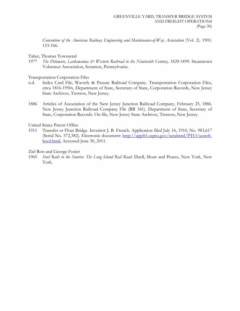
GREENVILLE YARD, TRANSFER BRIDGE SYSTEM AND FREIGHT OPERATIONS
(Page 30)
Convention of the American Railway Engineering and Maintenance-of-Way Association (Vol. 2). 1901: 153-166.
Taber, Thomas Townsend 1977 The Delaware, Lackawanna & Western Railroad in the Nineteenth Century, 1828-1899. Steamtown
Volunteer Association, Scranton, Pennsylvania. Transportation Corporation Files n.d. Index Card File, Waverly & Passaic Railroad Company. Transportation Corporation Files,
circa 1816-1950s, Department of State, Secretary of State, Corporation Records, New Jersey State Archives, Trenton, New Jersey.
1886 Articles of Association of the New Jersey Junction Railroad Company, February 25, 1886.
New Jersey Junction Railroad Company File (RR 341). Department of State, Secretary of State, Corporation Records. On file, New Jersey State Archives, Trenton, New Jersey.
United States Patent Office 1911 Transfer or Float Bridge. Inventor J. B. French. Application filed July 16, 1910, No. 983,617
(Serial No. 572,382). Electronic document: http://appft1.uspto.gov/netahtml/PTO/search-bool.html, Accessed June 30, 2011.
Ziel Ron and George Foster 1965 Steel Rails to the Sunrise: The Long Island Rail Road. Duell, Sloan and Pearce, New York, New
York.

GREENVILLE YARD, TRANSFER BRIDGE SYSTEM AND FREIGHT OPERATIONS
(Page 31)
VI. ATTACHMENTS

GREENVILLE YARD, TRANSFER BRIDGE SYSTEM AND FREIGHT OPERATIONS
(Page 32)
ATTACHMENT A: FIGURES
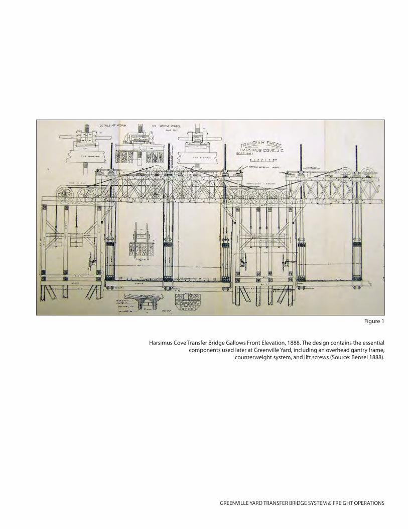
GREENVILLE YARD TRANSFER BRIDGE SYSTEM & FREIGHT OPERATIONS
Figure 1
Harsimus Cove Transfer Bridge Gallows Front Elevation, 1888. The design contains the essential components used later at Greenville Yard, including an overhead gantry frame,
counterweight system, and lift screws (Source: Bensel 1888).
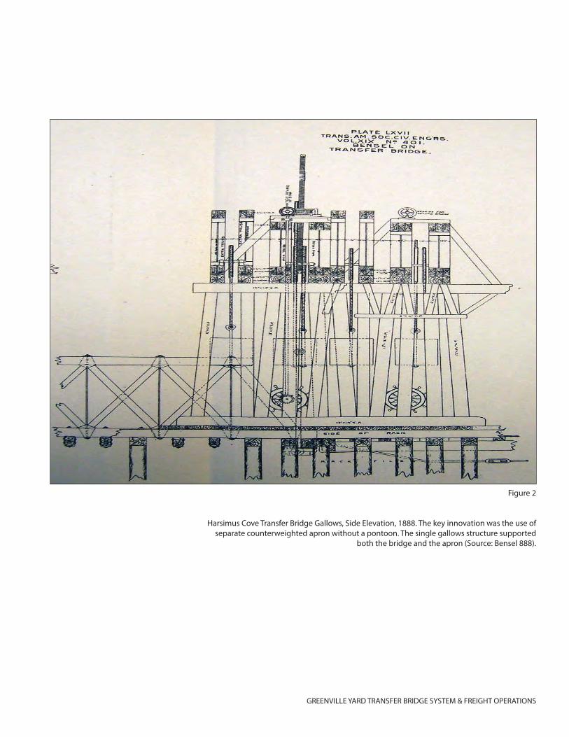
GREENVILLE YARD TRANSFER BRIDGE SYSTEM & FREIGHT OPERATIONS
Figure 2
Harsimus Cove Transfer Bridge Gallows, Side Elevation, 1888. The key innovation was the use of separate counterweighted apron without a pontoon. The single gallows structure supported
both the bridge and the apron (Source: Bensel 888).
GREENVILLE YARD TRANSFER BRIDGE SYSTEM & FREIGHT OPERATIONS
Figure 3
Harsimus Cove Transfer Bridge and Apron, Elevation and Plan, 1888. The timber structure con-sisted of a truss bridge and deck apron without pontoon (Source: Bensel 1888).
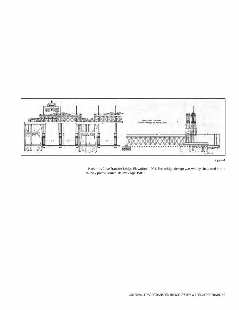
GREENVILLE YARD TRANSFER BRIDGE SYSTEM & FREIGHT OPERATIONS
Figure 4
Harsimus Cove Transfer Bridge Elevation , 1901. The bridge design was widely circulated in the railway press (Source: Railway Age 1901).
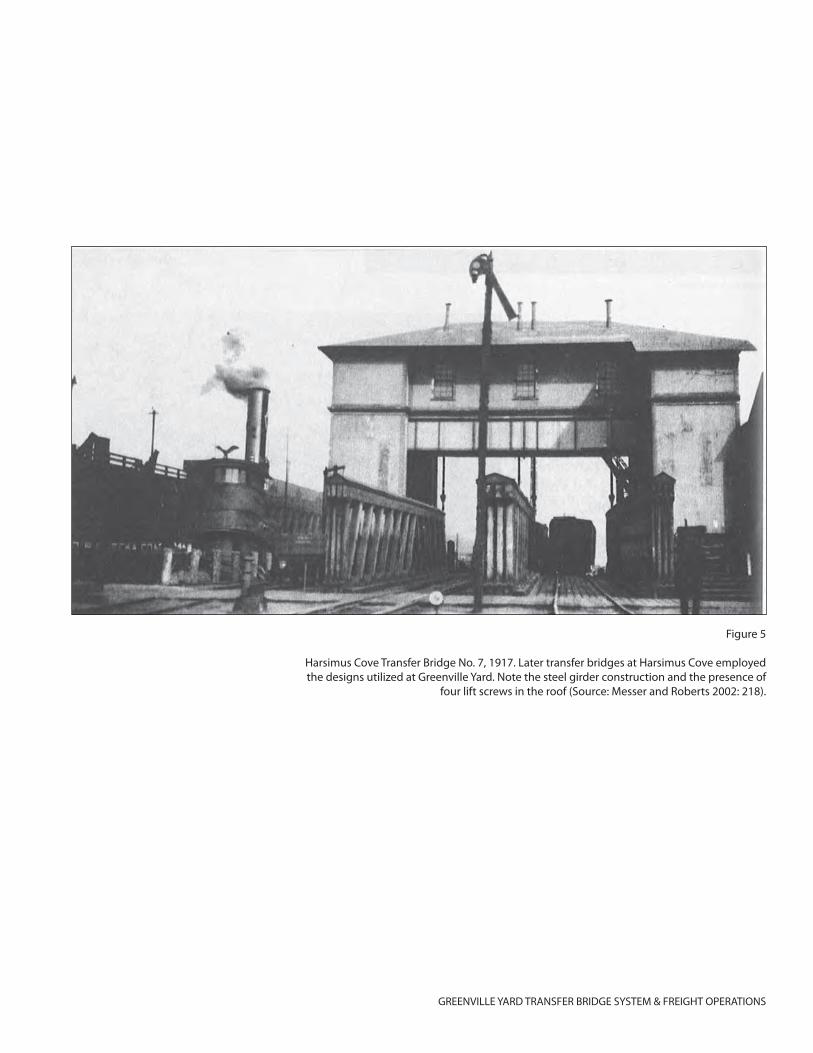
GREENVILLE YARD TRANSFER BRIDGE SYSTEM & FREIGHT OPERATIONS
Figure 5
Harsimus Cove Transfer Bridge No. 7, 1917. Later transfer bridges at Harsimus Cove employed the designs utilized at Greenville Yard. Note the steel girder construction and the presence of
four lift screws in the roof (Source: Messer and Roberts 2002: 218).
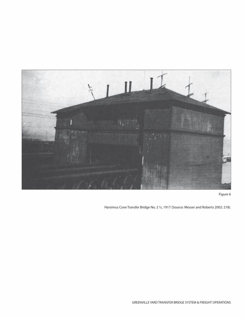
GREENVILLE YARD TRANSFER BRIDGE SYSTEM & FREIGHT OPERATIONS
Figure 6
Harsimus Cove Transfer Bridge No. 2 ½, 1917 (Source: Messer and Roberts 2002: 218).
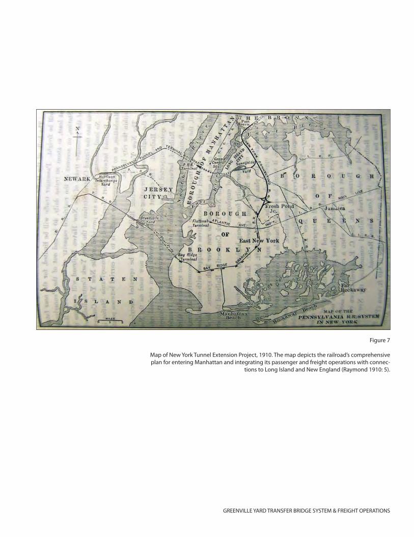
GREENVILLE YARD TRANSFER BRIDGE SYSTEM & FREIGHT OPERATIONS
Figure 7
Map of New York Tunnel Extension Project, 1910. The map depicts the railroad’s comprehensive plan for entering Manhattan and integrating its passenger and freight operations with connec-
tions to Long Island and New England (Raymond 1910: 5).
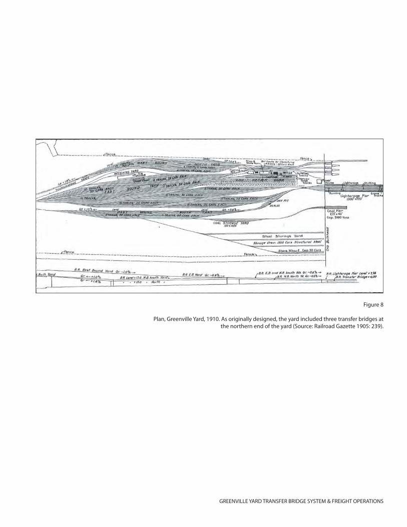
GREENVILLE YARD TRANSFER BRIDGE SYSTEM & FREIGHT OPERATIONS
Figure 8
Plan, Greenville Yard, 1910. As originally designed, the yard included three transfer bridges at the northern end of the yard (Source: Railroad Gazette 1905: 239).
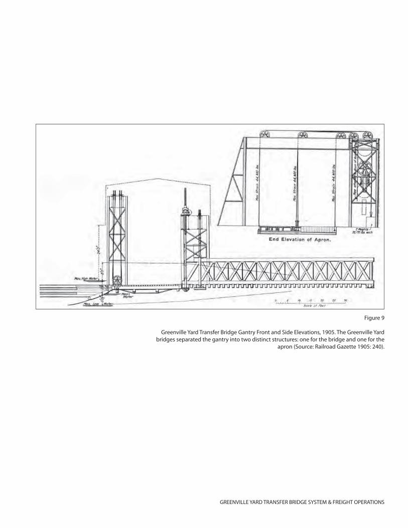
GREENVILLE YARD TRANSFER BRIDGE SYSTEM & FREIGHT OPERATIONS
Figure 9
Greenville Yard Transfer Bridge Gantry Front and Side Elevations, 1905. The Greenville Yard bridges separated the gantry into two distinct structures: one for the bridge and one for the
apron (Source: Railroad Gazette 1905: 240).
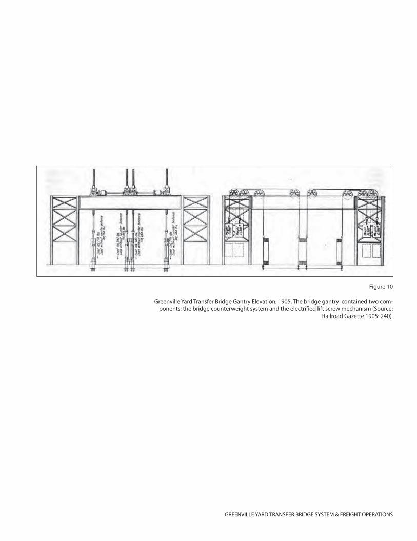
GREENVILLE YARD TRANSFER BRIDGE SYSTEM & FREIGHT OPERATIONS
Figure 10
Greenville Yard Transfer Bridge Gantry Elevation, 1905. The bridge gantry contained two com-ponents: the bridge counterweight system and the electrifi ed lift screw mechanism (Source:
Railroad Gazette 1905: 240).
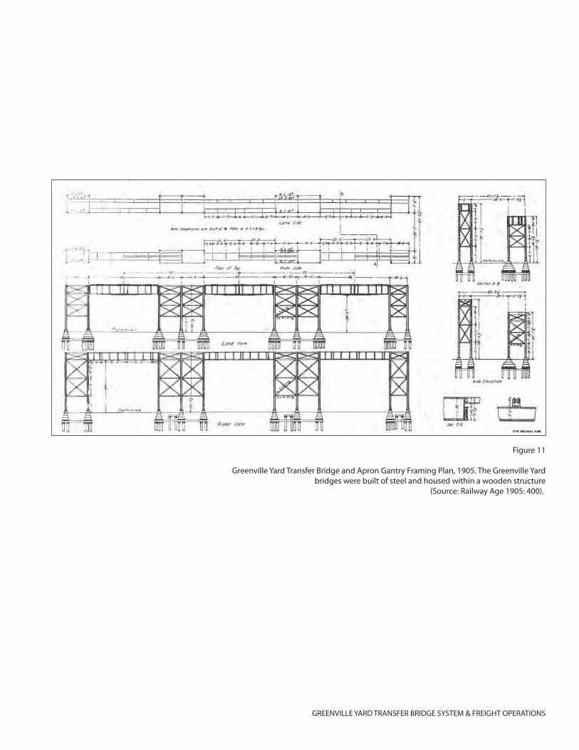
GREENVILLE YARD TRANSFER BRIDGE SYSTEM & FREIGHT OPERATIONS
Figure 11
Greenville Yard Transfer Bridge and Apron Gantry Framing Plan, 1905. The Greenville Yard bridges were built of steel and housed within a wooden structure
(Source: Railway Age 1905: 400).
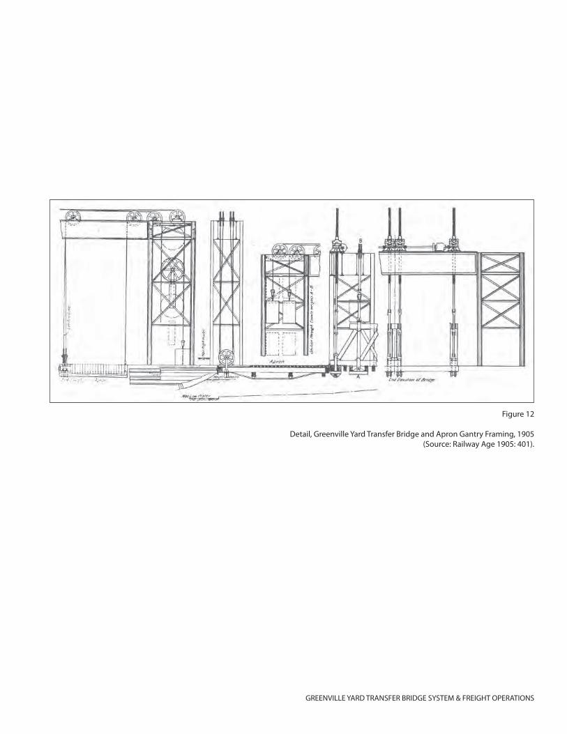
GREENVILLE YARD TRANSFER BRIDGE SYSTEM & FREIGHT OPERATIONS
Figure 12
Detail, Greenville Yard Transfer Bridge and Apron Gantry Framing, 1905(Source: Railway Age 1905: 401).
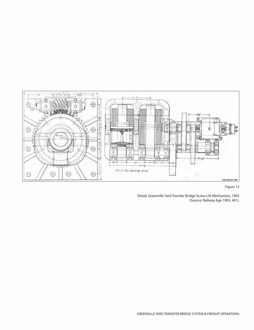
GREENVILLE YARD TRANSFER BRIDGE SYSTEM & FREIGHT OPERATIONS
Figure 13
Detail, Greenville Yard Transfer Bridge Screw Lift Mechanism, 1905(Source: Railway Age 1905: 401).
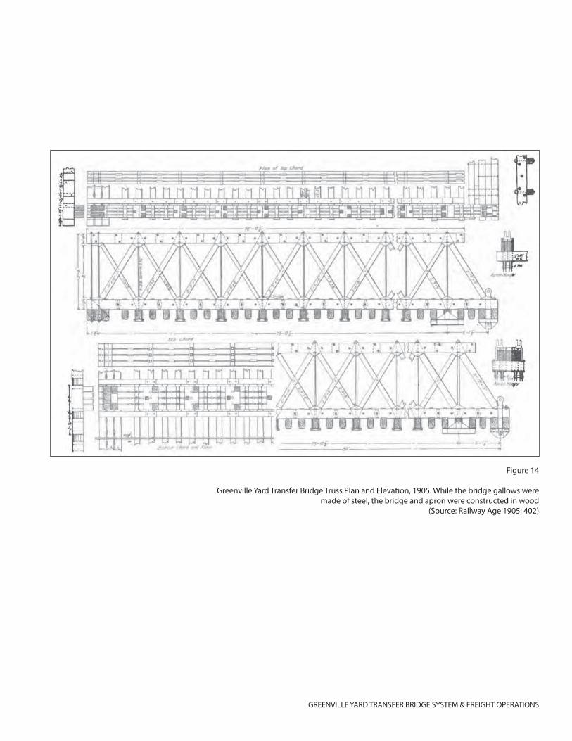
GREENVILLE YARD TRANSFER BRIDGE SYSTEM & FREIGHT OPERATIONS
Figure 14
Greenville Yard Transfer Bridge Truss Plan and Elevation, 1905. While the bridge gallows were made of steel, the bridge and apron were constructed in wood
(Source: Railway Age 1905: 402)
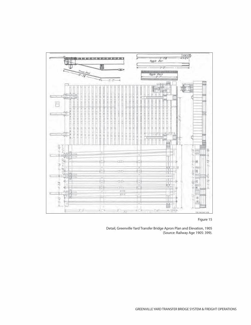
GREENVILLE YARD TRANSFER BRIDGE SYSTEM & FREIGHT OPERATIONS
Figure 15
Detail, Greenville Yard Transfer Bridge Apron Plan and Elevation, 1905(Source: Railway Age 1905: 399).
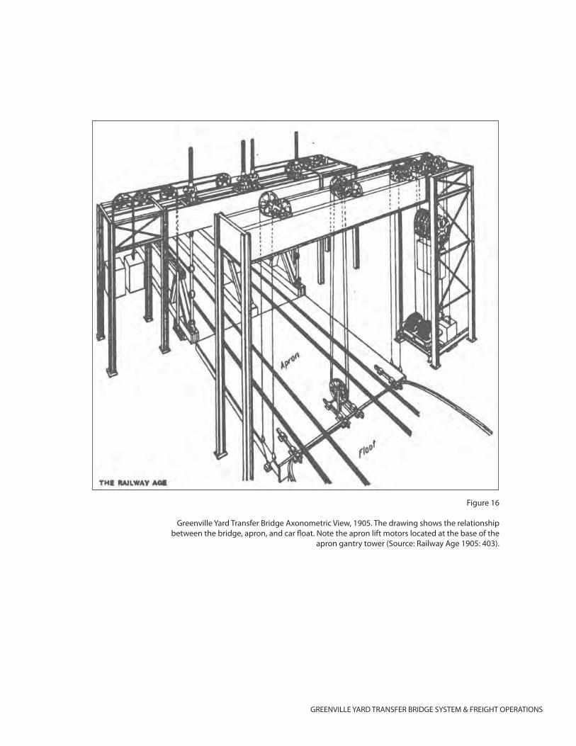
GREENVILLE YARD TRANSFER BRIDGE SYSTEM & FREIGHT OPERATIONS
Figure 16
Greenville Yard Transfer Bridge Axonometric View, 1905. The drawing shows the relationship between the bridge, apron, and car fl oat. Note the apron lift motors located at the base of the
apron gantry tower (Source: Railway Age 1905: 403).
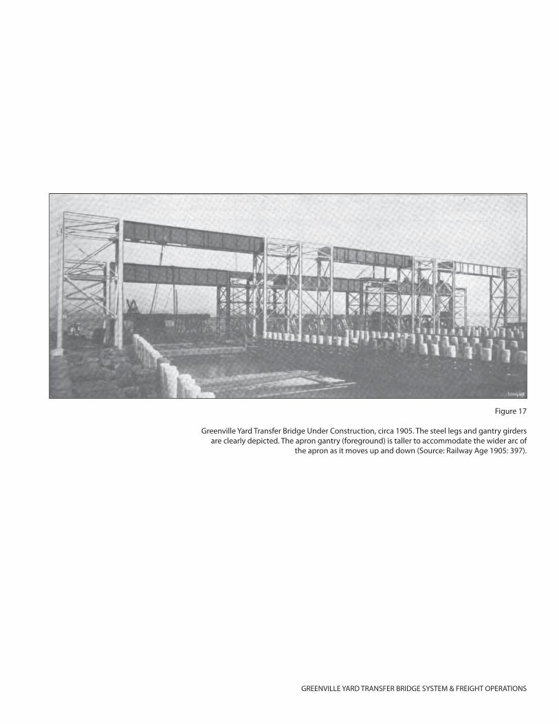
GREENVILLE YARD TRANSFER BRIDGE SYSTEM & FREIGHT OPERATIONS
Figure 17
Greenville Yard Transfer Bridge Under Construction, circa 1905. The steel legs and gantry girders are clearly depicted. The apron gantry (foreground) is taller to accommodate the wider arc of
the apron as it moves up and down (Source: Railway Age 1905: 397).
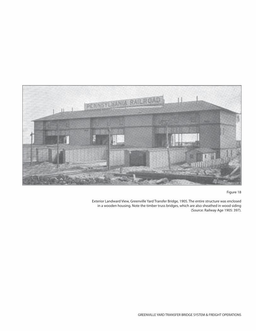
GREENVILLE YARD TRANSFER BRIDGE SYSTEM & FREIGHT OPERATIONS
Figure 18
Exterior Landward View, Greenville Yard Transfer Bridge, 1905. The entire structure was enclosed in a wooden housing. Note the timber truss bridges, which are also sheathed in wood siding
(Source: Railway Age 1905: 397).
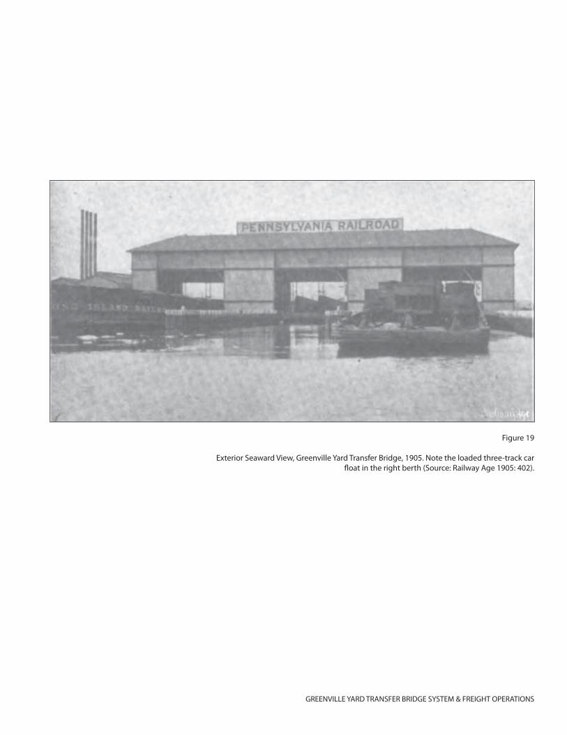
GREENVILLE YARD TRANSFER BRIDGE SYSTEM & FREIGHT OPERATIONS
Figure 19
Exterior Seaward View, Greenville Yard Transfer Bridge, 1905. Note the loaded three-track car fl oat in the right berth (Source: Railway Age 1905: 402).
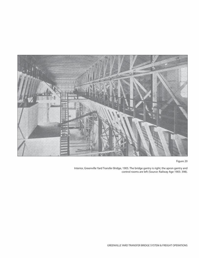
GREENVILLE YARD TRANSFER BRIDGE SYSTEM & FREIGHT OPERATIONS
Figure 20
Interior, Greenville Yard Transfer Bridge, 1905. The bridge gantry is right; the apron gantry and control rooms are left (Source: Railway Age 1905: 398).
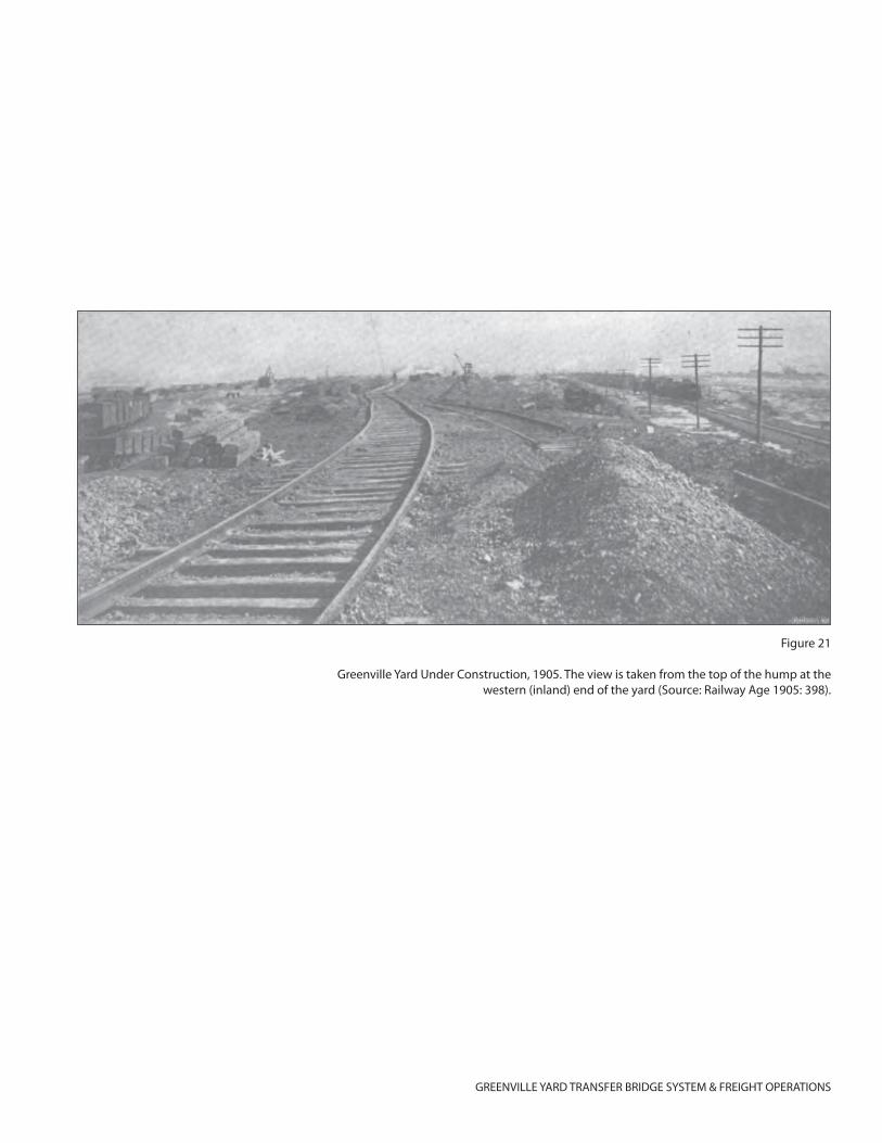
GREENVILLE YARD TRANSFER BRIDGE SYSTEM & FREIGHT OPERATIONS
Figure 21
Greenville Yard Under Construction, 1905. The view is taken from the top of the hump at the western (inland) end of the yard (Source: Railway Age 1905: 398).
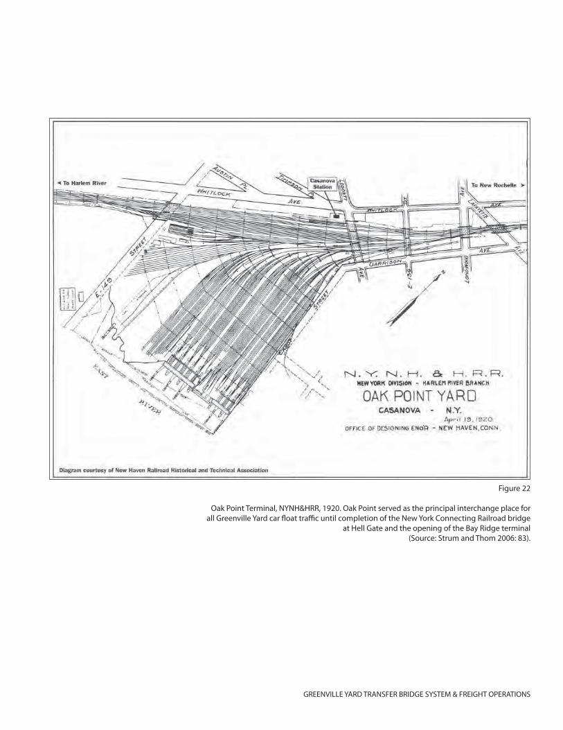
GREENVILLE YARD TRANSFER BRIDGE SYSTEM & FREIGHT OPERATIONS
Figure 22
Oak Point Terminal, NYNH&HRR, 1920. Oak Point served as the principal interchange place for all Greenville Yard car fl oat traffi c until completion of the New York Connecting Railroad bridge
at Hell Gate and the opening of the Bay Ridge terminal(Source: Strum and Thom 2006: 83).
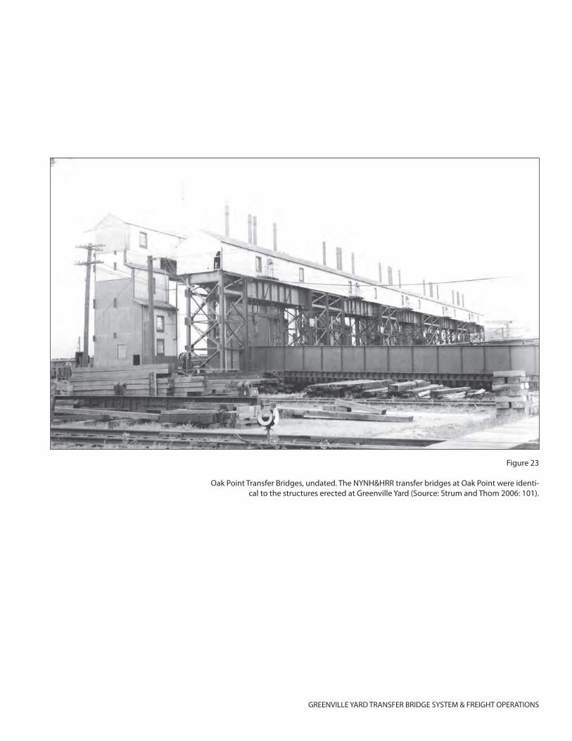
GREENVILLE YARD TRANSFER BRIDGE SYSTEM & FREIGHT OPERATIONS
Figure 23
Oak Point Transfer Bridges, undated. The NYNH&HRR transfer bridges at Oak Point were identi-cal to the structures erected at Greenville Yard (Source: Strum and Thom 2006: 101).
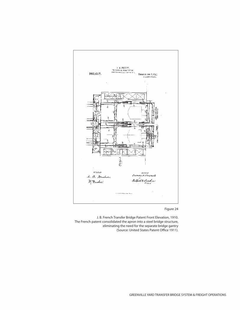
GREENVILLE YARD TRANSFER BRIDGE SYSTEM & FREIGHT OPERATIONS
Figure 24
J. B. French Transfer Bridge Patent Front Elevation, 1910.The French patent consolidated the apron into a steel bridge structure,
eliminating the need for the separate bridge gantry(Source: United States Patent Offi ce 1911).
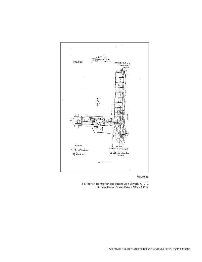
GREENVILLE YARD TRANSFER BRIDGE SYSTEM & FREIGHT OPERATIONS
Figure 25
J. B. French Transfer Bridge Patent Side Elevation, 1910(Source: United States Patent Offi ce 1911).
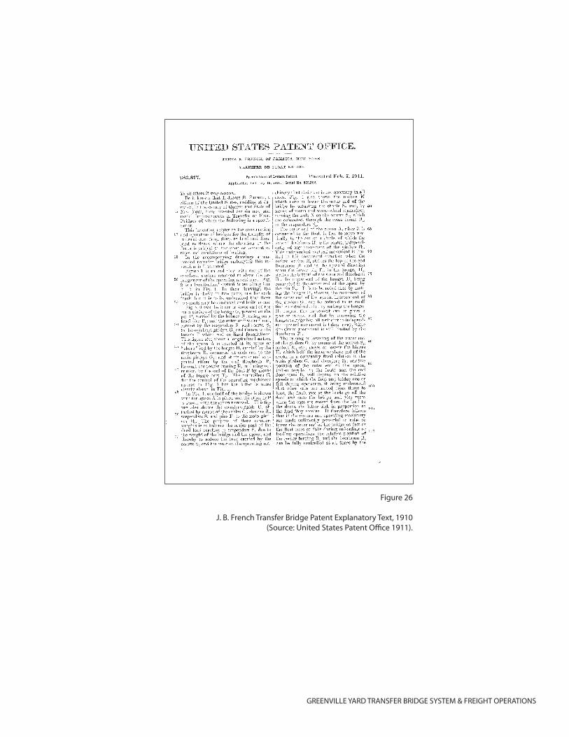
GREENVILLE YARD TRANSFER BRIDGE SYSTEM & FREIGHT OPERATIONS
Figure 26
J. B. French Transfer Bridge Patent Explanatory Text, 1910(Source: United States Patent Offi ce 1911).
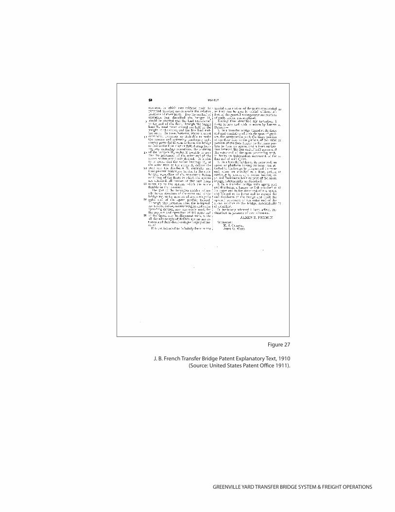
GREENVILLE YARD TRANSFER BRIDGE SYSTEM & FREIGHT OPERATIONS
Figure 27
J. B. French Transfer Bridge Patent Explanatory Text, 1910(Source: United States Patent Offi ce 1911).
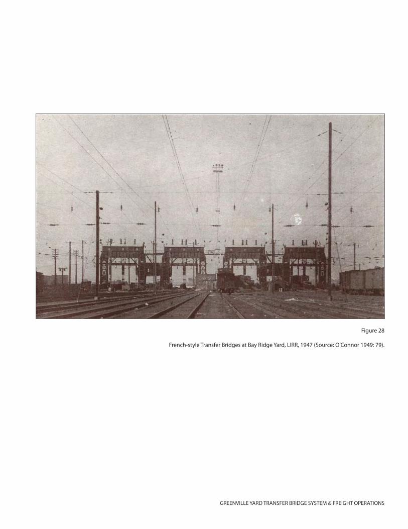
GREENVILLE YARD TRANSFER BRIDGE SYSTEM & FREIGHT OPERATIONS
Figure 28
French-style Transfer Bridges at Bay Ridge Yard, LIRR, 1947 (Source: O’Connor 1949: 79).
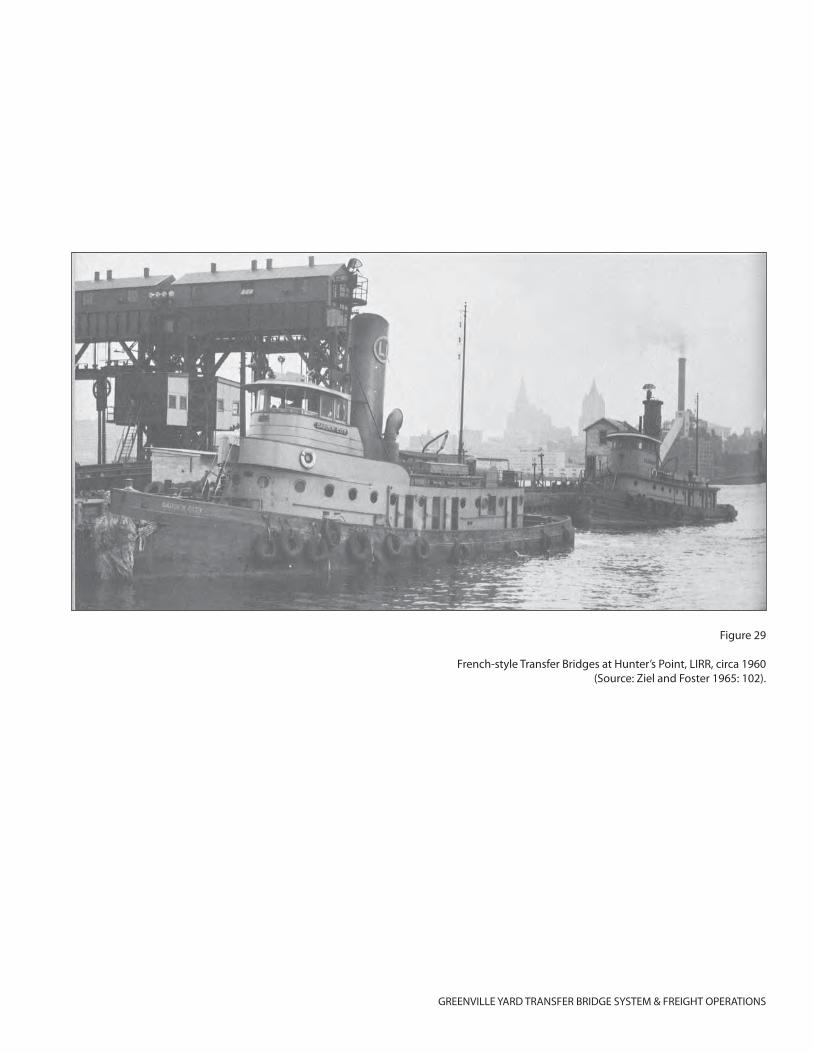
GREENVILLE YARD TRANSFER BRIDGE SYSTEM & FREIGHT OPERATIONS
Figure 29
French-style Transfer Bridges at Hunter’s Point, LIRR, circa 1960(Source: Ziel and Foster 1965: 102).
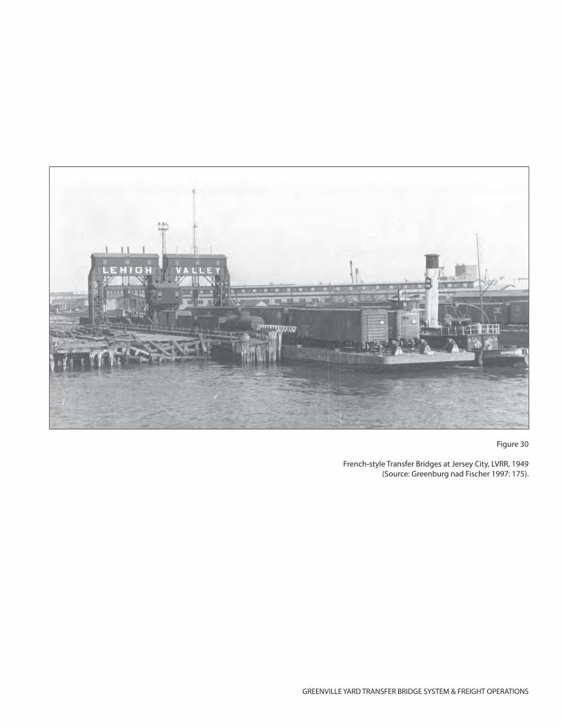
GREENVILLE YARD TRANSFER BRIDGE SYSTEM & FREIGHT OPERATIONS
Figure 30
French-style Transfer Bridges at Jersey City, LVRR, 1949(Source: Greenburg nad Fischer 1997: 175).
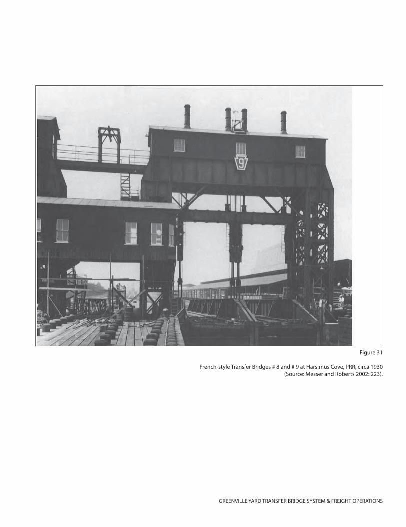
GREENVILLE YARD TRANSFER BRIDGE SYSTEM & FREIGHT OPERATIONS
Figure 31
French-style Transfer Bridges # 8 and # 9 at Harsimus Cove, PRR, circa 1930(Source: Messer and Roberts 2002: 223).
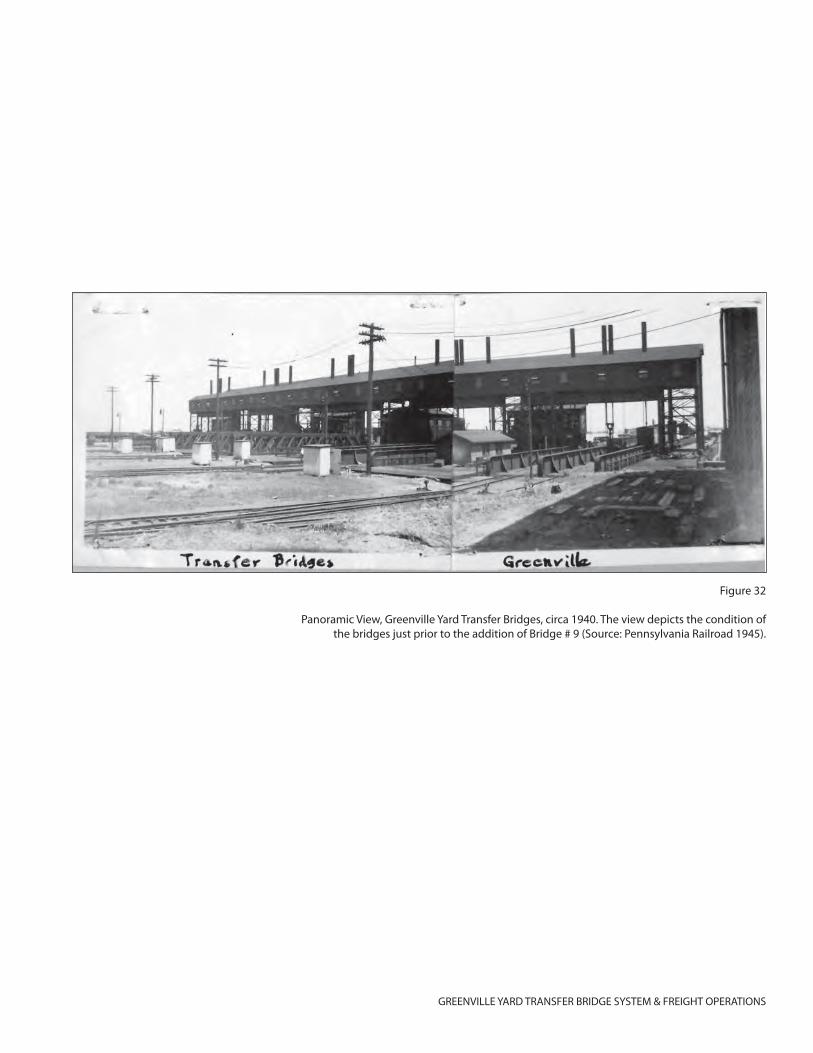
GREENVILLE YARD TRANSFER BRIDGE SYSTEM & FREIGHT OPERATIONS
Figure 32
Panoramic View, Greenville Yard Transfer Bridges, circa 1940. The view depicts the condition of the bridges just prior to the addition of Bridge # 9 (Source: Pennsylvania Railroad 1945).
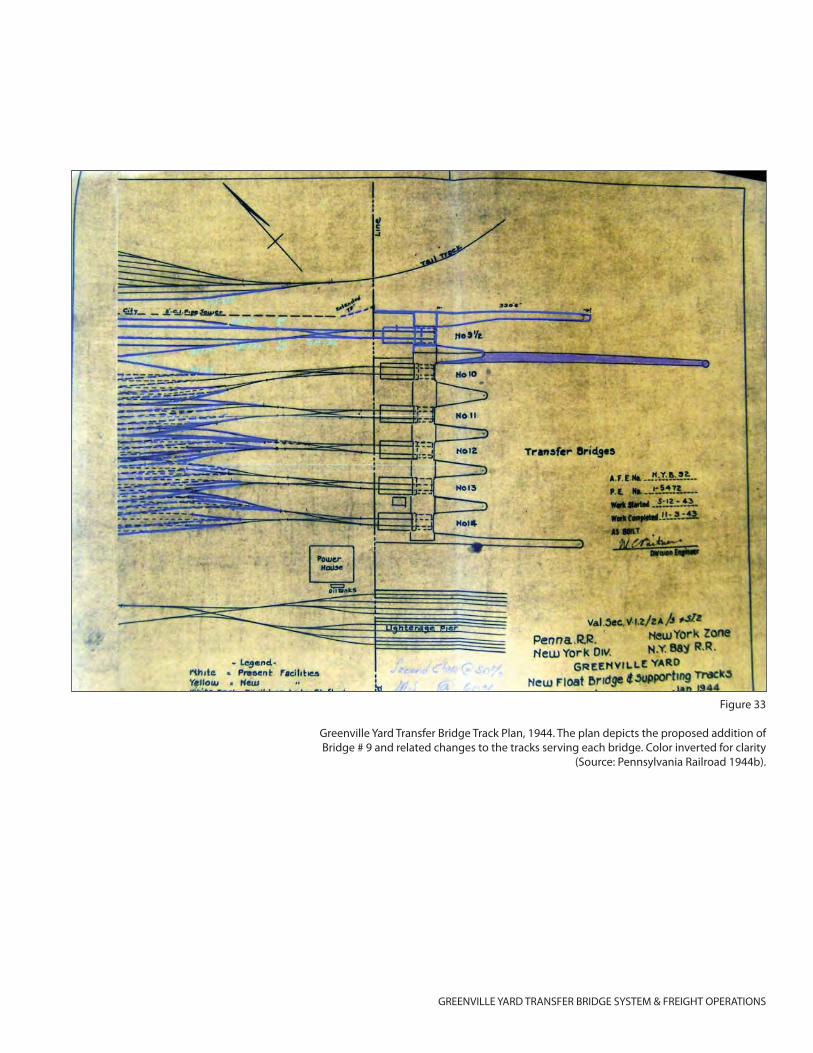
GREENVILLE YARD TRANSFER BRIDGE SYSTEM & FREIGHT OPERATIONS
Figure 33
Greenville Yard Transfer Bridge Track Plan, 1944. The plan depicts the proposed addition of Bridge # 9 and related changes to the tracks serving each bridge. Color inverted for clarity
(Source: Pennsylvania Railroad 1944b).
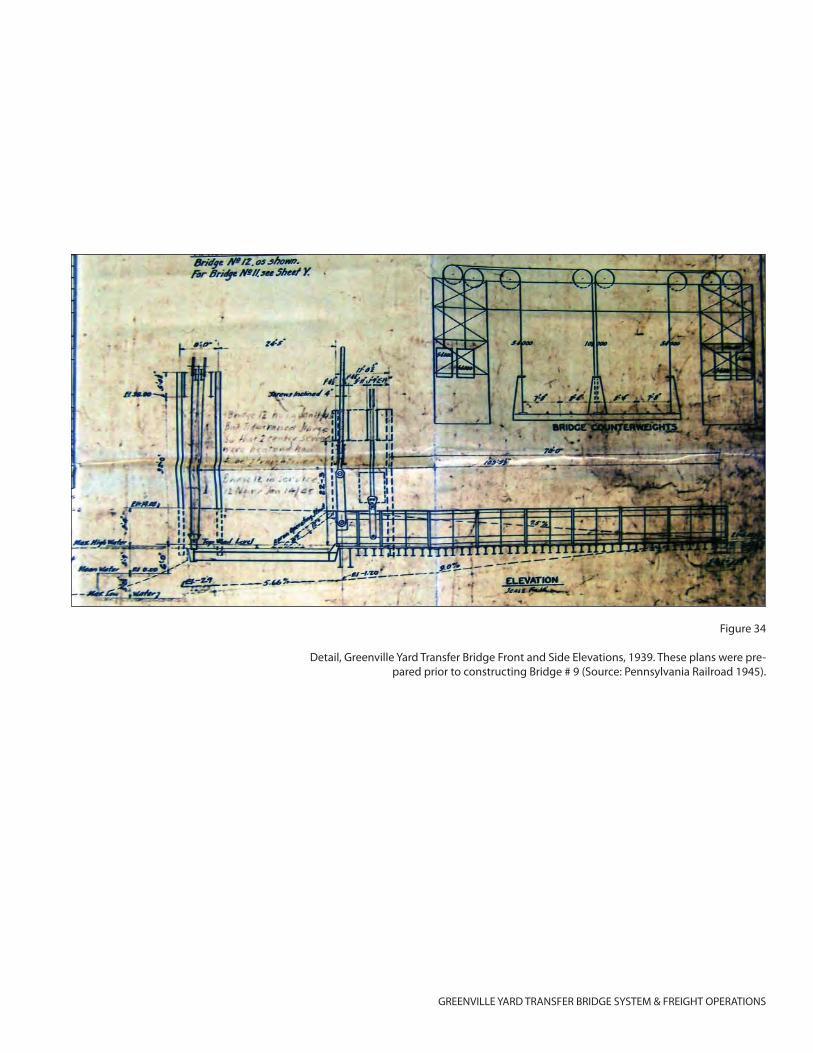
GREENVILLE YARD TRANSFER BRIDGE SYSTEM & FREIGHT OPERATIONS
Figure 34
Detail, Greenville Yard Transfer Bridge Front and Side Elevations, 1939. These plans were pre-pared prior to constructing Bridge # 9 (Source: Pennsylvania Railroad 1945).
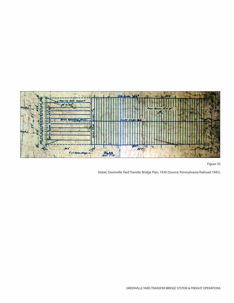
GREENVILLE YARD TRANSFER BRIDGE SYSTEM & FREIGHT OPERATIONS
Figure 35
Detail, Greenville Yard Transfer Bridge Plan, 1939 (Source: Pennsylvania Railroad 1945).
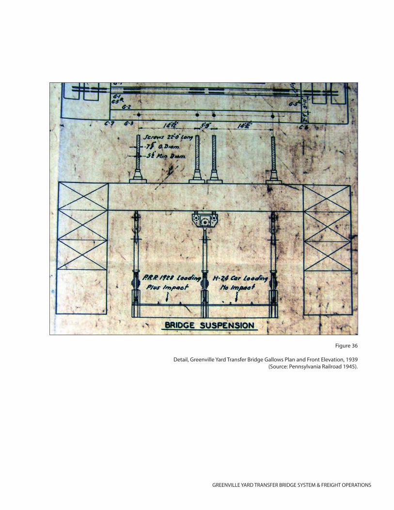
GREENVILLE YARD TRANSFER BRIDGE SYSTEM & FREIGHT OPERATIONS
Figure 36
Detail, Greenville Yard Transfer Bridge Gallows Plan and Front Elevation, 1939(Source: Pennsylvania Railroad 1945).
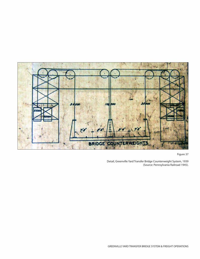
GREENVILLE YARD TRANSFER BRIDGE SYSTEM & FREIGHT OPERATIONS
Figure 37
Detail, Greenville Yard Transfer Bridge Counterweight System, 1939(Source: Pennsylvania Railroad 1945).
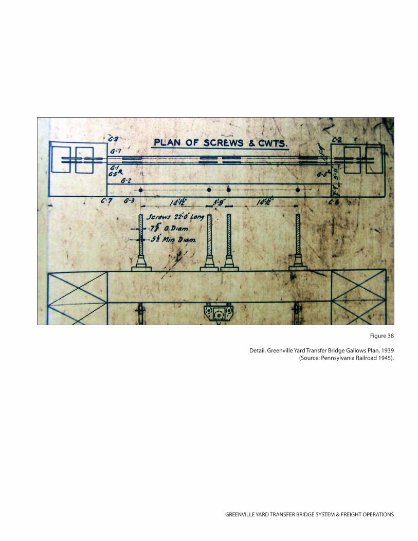
GREENVILLE YARD TRANSFER BRIDGE SYSTEM & FREIGHT OPERATIONS
Figure 38
Detail, Greenville Yard Transfer Bridge Gallows Plan, 1939(Source: Pennsylvania Railroad 1945).
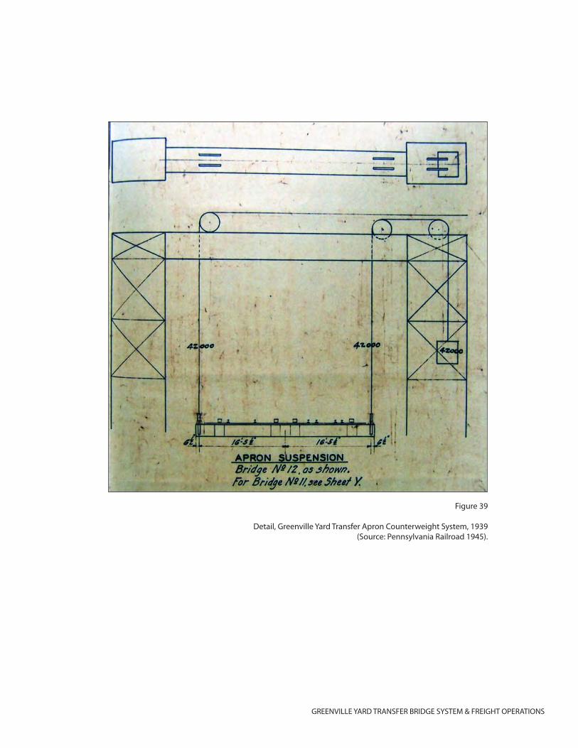
GREENVILLE YARD TRANSFER BRIDGE SYSTEM & FREIGHT OPERATIONS
Figure 39
Detail, Greenville Yard Transfer Apron Counterweight System, 1939(Source: Pennsylvania Railroad 1945).
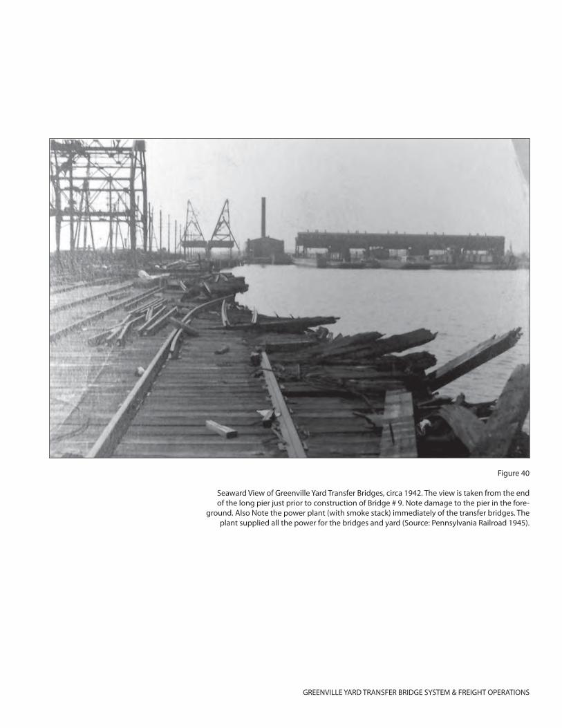
GREENVILLE YARD TRANSFER BRIDGE SYSTEM & FREIGHT OPERATIONS
Figure 40
Seaward View of Greenville Yard Transfer Bridges, circa 1942. The view is taken from the end of the long pier just prior to construction of Bridge # 9. Note damage to the pier in the fore-
ground. Also Note the power plant (with smoke stack) immediately of the transfer bridges. The plant supplied all the power for the bridges and yard (Source: Pennsylvania Railroad 1945).
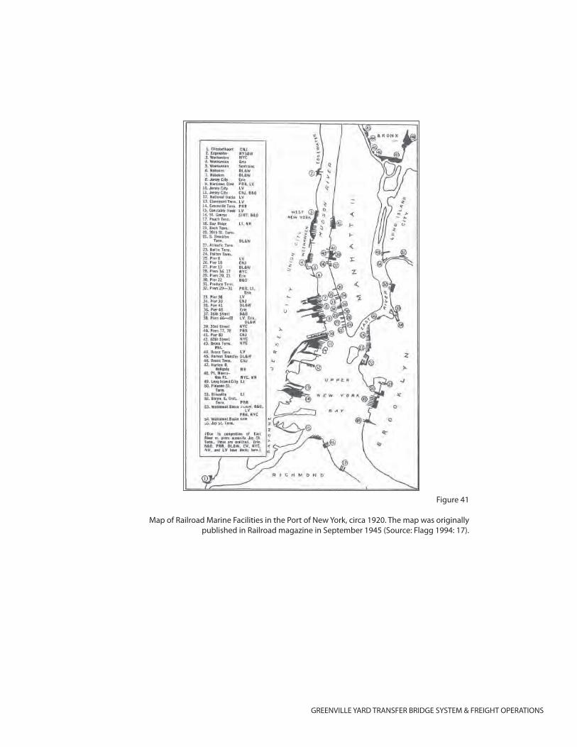
GREENVILLE YARD TRANSFER BRIDGE SYSTEM & FREIGHT OPERATIONS
Figure 41
Map of Railroad Marine Facilities in the Port of New York, circa 1920. The map was originally published in Railroad magazine in September 1945 (Source: Flagg 1994: 17).
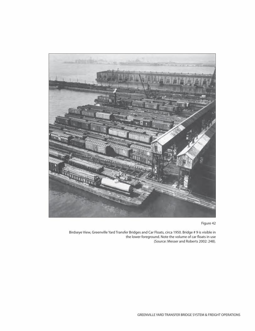
GREENVILLE YARD TRANSFER BRIDGE SYSTEM & FREIGHT OPERATIONS
Figure 42
Birdseye View, Greenville Yard Transfer Bridges and Car Floats, circa 1950. Bridge # 9 is visible in the lower foreground. Note the volume of car fl oats in use
(Source: Messer and Roberts 2002: 248).
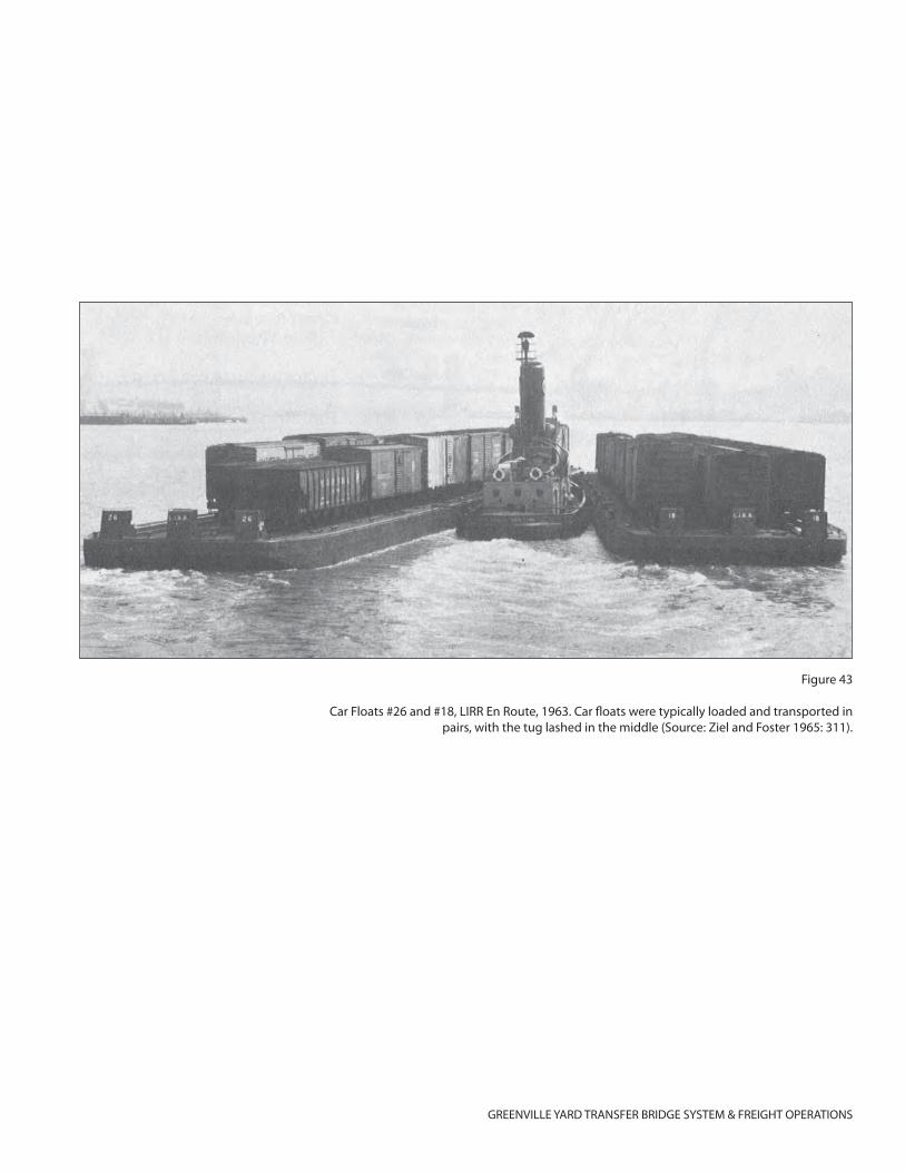
GREENVILLE YARD TRANSFER BRIDGE SYSTEM & FREIGHT OPERATIONS
Figure 43
Car Floats #26 and #18, LIRR En Route, 1963. Car fl oats were typically loaded and transported in pairs, with the tug lashed in the middle (Source: Ziel and Foster 1965: 311).
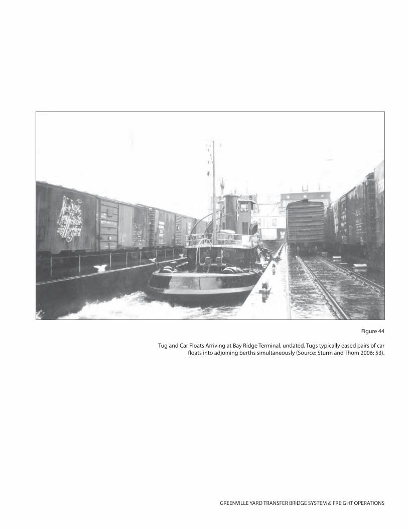
GREENVILLE YARD TRANSFER BRIDGE SYSTEM & FREIGHT OPERATIONS
Figure 44
Tug and Car Floats Arriving at Bay Ridge Terminal, undated. Tugs typically eased pairs of car fl oats into adjoining berths simultaneously (Source: Sturm and Thom 2006: 53).
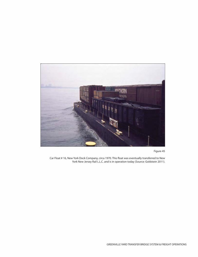
GREENVILLE YARD TRANSFER BRIDGE SYSTEM & FREIGHT OPERATIONS
Figure 45
Car Float # 16, New York Dock Company, circa 1970. This fl oat was eventually transferred to New York New Jersey Rail L.L.C. and is in operation today (Source: Goldstein 2011).
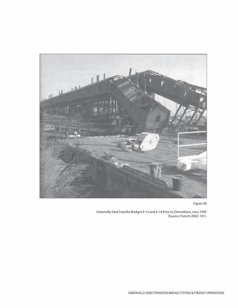
GREENVILLE YARD TRANSFER BRIDGE SYSTEM & FREIGHT OPERATIONS
Figure 46
Greenville Yard Transfer Bridges # 13 and # 14 Prior to Demolition, circa 1995(Source: French 2002: 101).

GREENVILLE YARD, TRANSFER BRIDGE SYSTEM AND FREIGHT OPERATIONS
(Page 33)
ATTACHMENT B: SUPPLEMENTAL MATERIAL
[TO COME]

GREENVILLE YARD, TRANSFER BRIDGE SYSTEM AND FREIGHT OPERATIONS
(Page 34)
ATTACHMENT C: PHOTO RECORDATION
[TO COME]
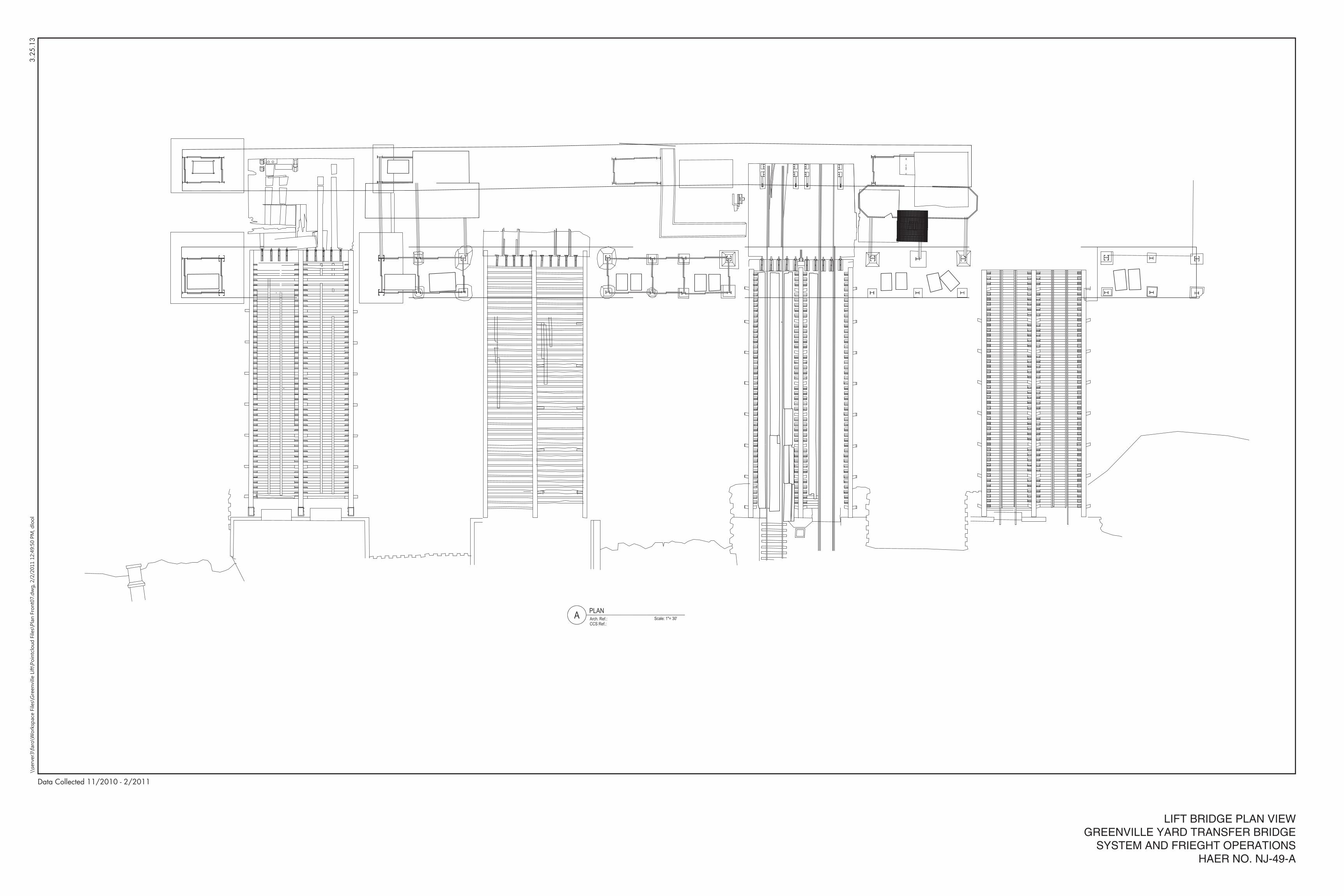
3.25
.13
LIFT BRIDGE PLAN VIEWGREENVILLE YARD TRANSFER BRIDGE
SYSTEM AND FRIEGHT OPERATIONSHAER NO. NJ-49-A
Data Collected 11/2010 - 2/2011
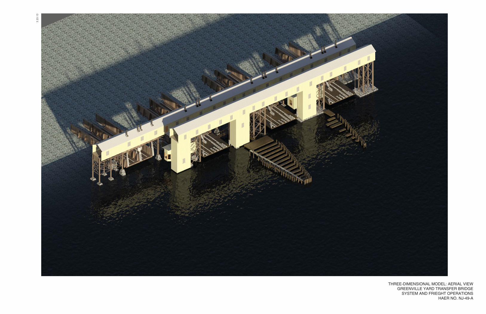
3.25
.13
THREE-DIMENSIONAL MODEL: AERIAL VIEWGREENVILLE YARD TRANSFER BRIDGE
SYSTEM AND FRIEGHT OPERATIONSHAER NO. NJ-49-A
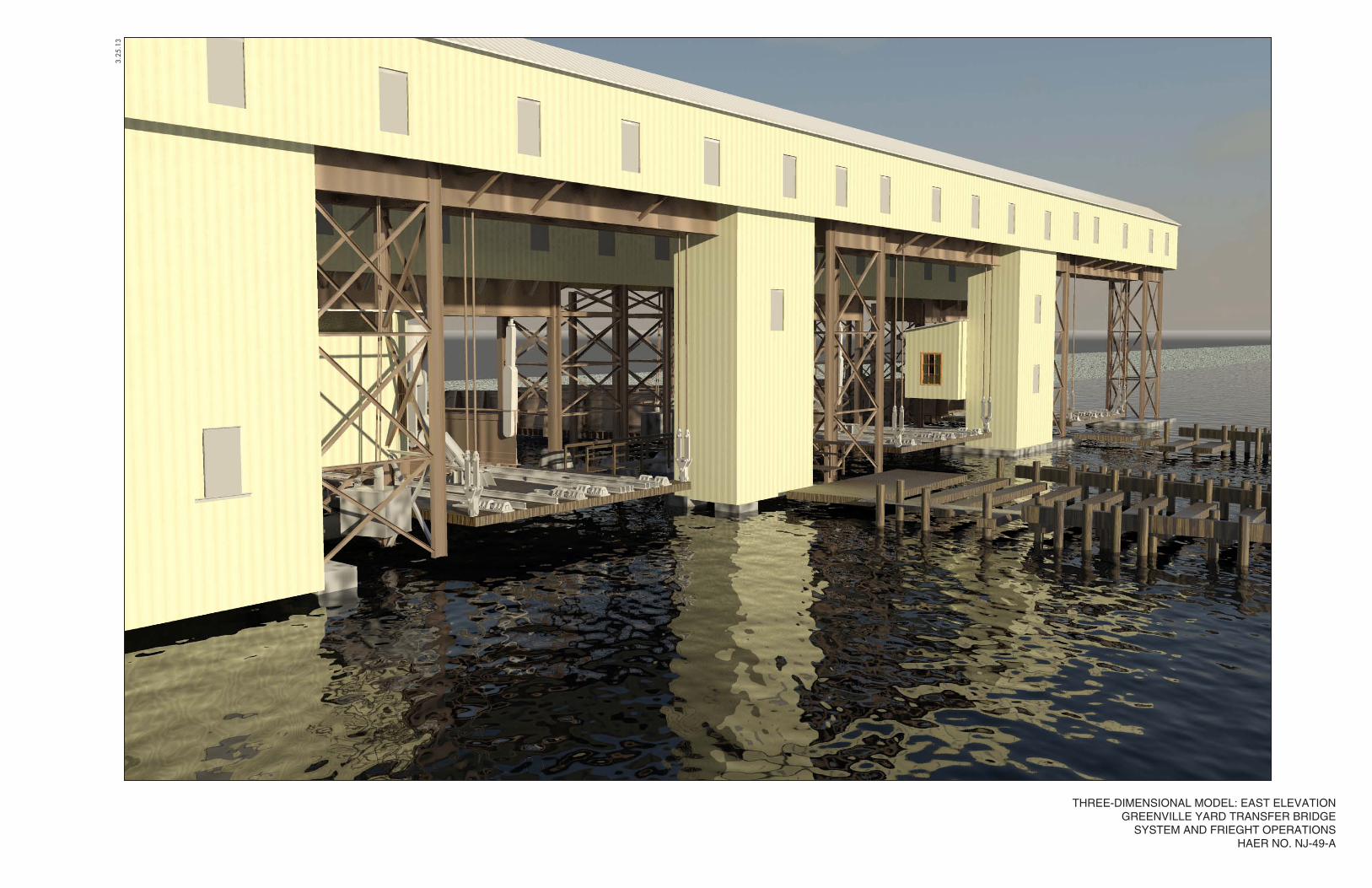
3.25
.13
THREE-DIMENSIONAL MODEL: EAST ELEVATIONGREENVILLE YARD TRANSFER BRIDGE
SYSTEM AND FRIEGHT OPERATIONSHAER NO. NJ-49-A
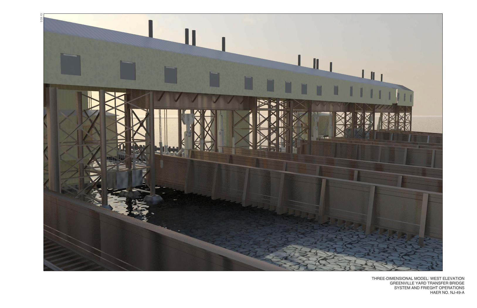
3.25
.13
THREE-DIMENSIONAL MODEL: WEST ELEVATIONGREENVILLE YARD TRANSFER BRIDGE
SYSTEM AND FRIEGHT OPERATIONSHAER NO. NJ-49-A
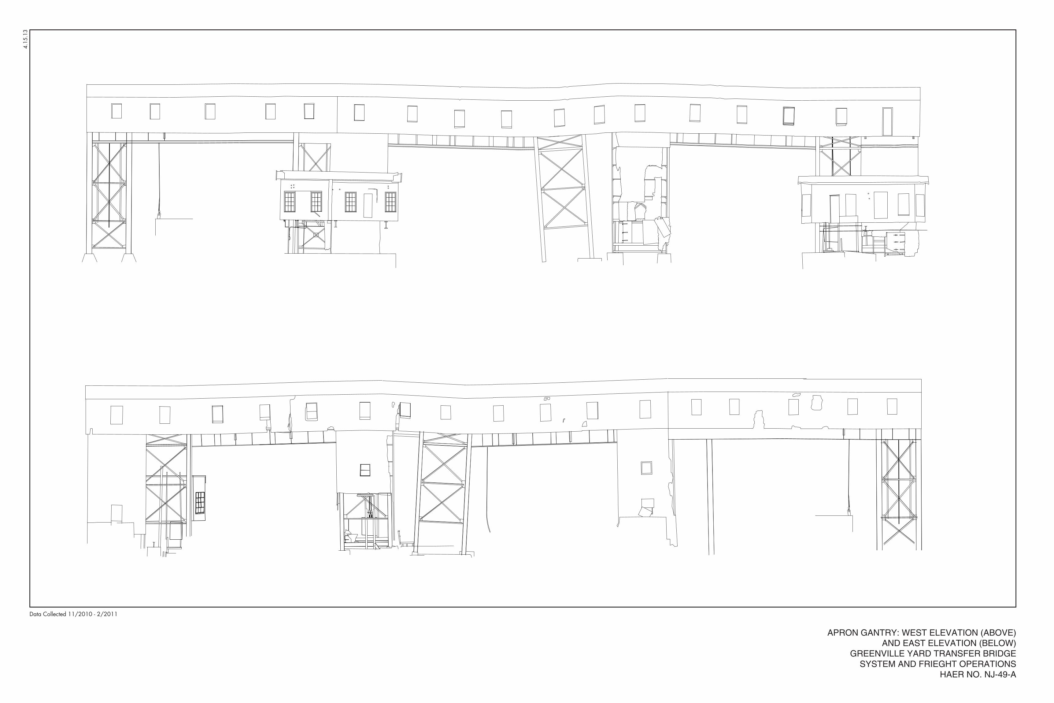
4.15
.13
APRON GANTRY: WEST ELEVATION (ABOVE)AND EAST ELEVATION (BELOW)
GREENVILLE YARD TRANSFER BRIDGESYSTEM AND FRIEGHT OPERATIONS
HAER NO. NJ-49-A
Data Collected 11/2010 - 2/2011
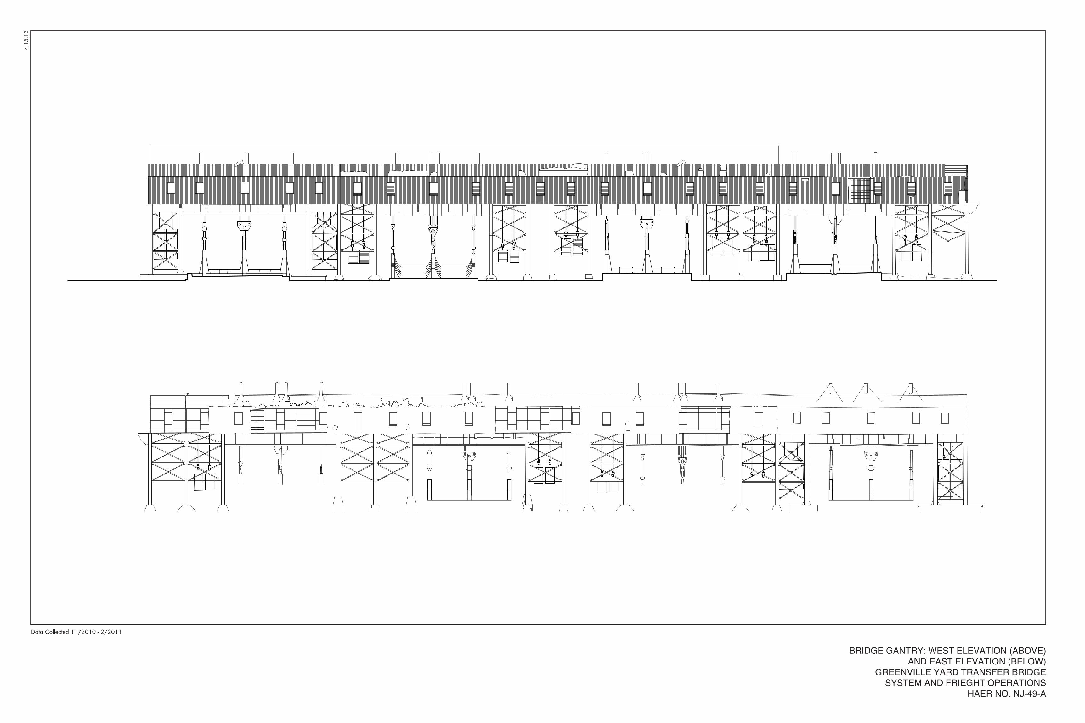
4.15
.13
BRIDGE GANTRY: WEST ELEVATION (ABOVE)AND EAST ELEVATION (BELOW)
GREENVILLE YARD TRANSFER BRIDGESYSTEM AND FRIEGHT OPERATIONS
HAER NO. NJ-49-A
Data Collected 11/2010 - 2/2011
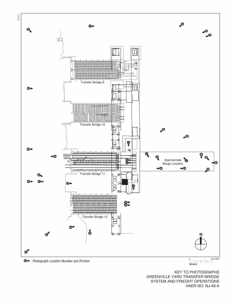
9.15
.11
N
SCALE
0 100 FEET
KEY TO PHOTOGRAPHSGREENVILLE YARD TRANSFER BRIDGE
SYSTEM AND FRIEGHT OPERATIONSHAER NO. NJ-49-A
Transfer Bridge 9
Transfer Bridge 10
Transfer Bridge 11
Transfer Bridge 12
ApproximateBarge Location
60
65
58 61
62
63
64
59
5755
56
55
56
74
70
69
68
7678
73
72
7577
84 83 88
66
8582
71
7981
67
Photograph Location Number and Dirction55
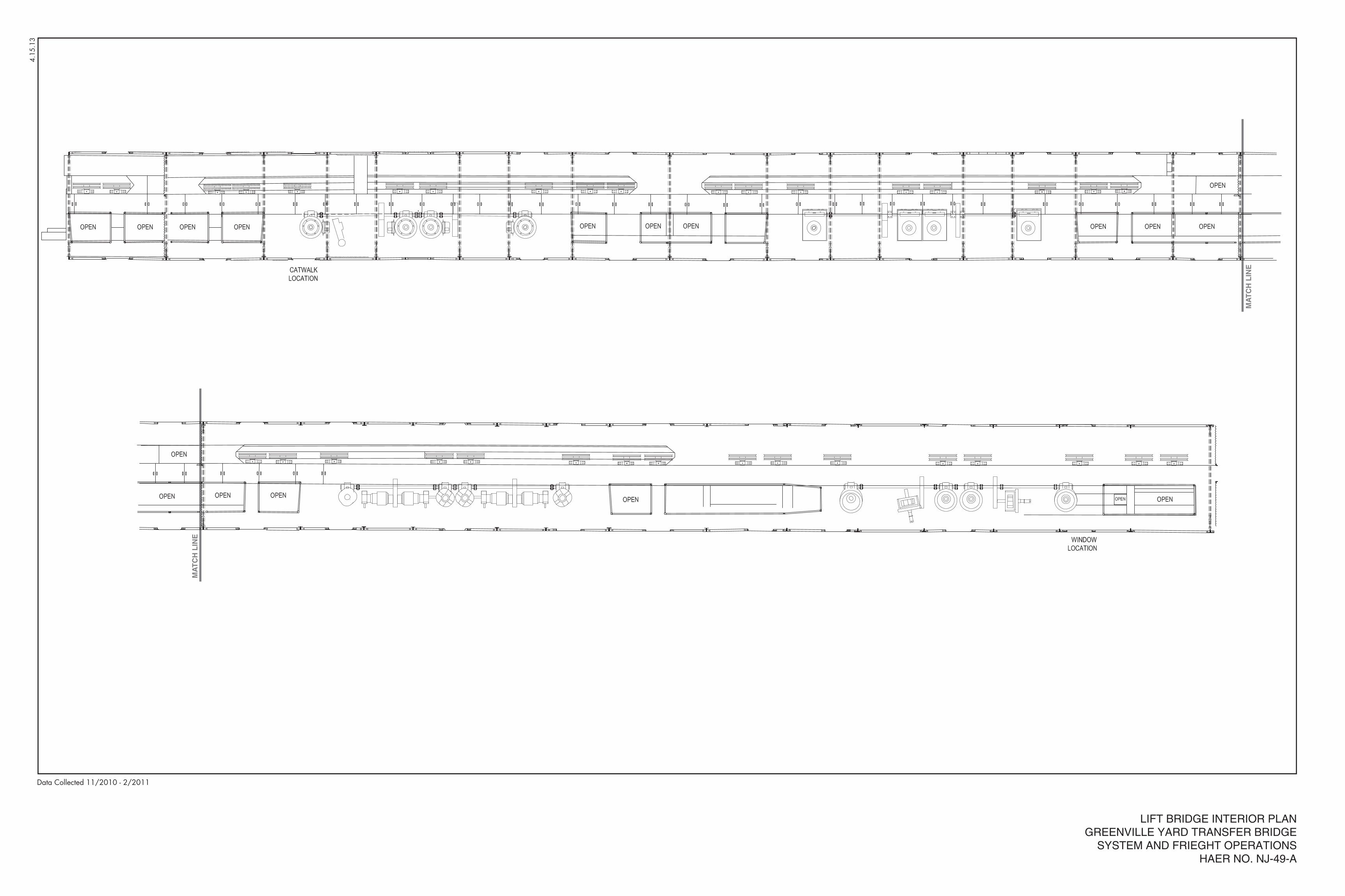
4.1
5.13
LIFT BRIDGE INTERIOR PLANGREENVILLE YARD TRANSFER BRIDGE
SYSTEM AND FRIEGHT OPERATIONSHAER NO. NJ-49-A
Data Collected 11/2010 - 2/2011
MA
TC
H L
INE
MA
TC
H L
INE
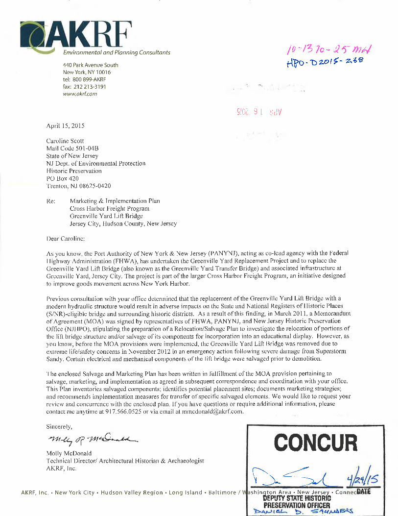
1
Greenville Yard Salvage and Marketing Plan
A. INTRODUCTION
The Port Authority of New York & New Jersey (PANYNJ), acting as co-lead agency with theFederal Highway Administration (FHWA), is advancing the Cross Harbor Freight Program withthe goal of improving goods movement across New York Harbor and the Hudson River. As partof the overall Cross Harbor Freight Program, PANYNJ is undertaking several near-term freightnetwork improvements in various locations in New York and New Jersey, including therehabilitation and improvement of Greenville Yard in Jersey City, New Jersey. Previousenvironmental review has determined that the replacement of the Greenville Yard Lift Bridgewith a modern hydraulic structure would result in adverse impacts on the State and NationalRegisters of Historic Places (S/NR) eligible bridge and surrounding historic districts. As a resultof this finding, in March 2011, a Memorandum of Agreement (MOA) was signed byrepresentatives of FHWA, PANYNJ, and New Jersey Historic Preservation Office (NJHPO),stipulating the preparation of a Relocation/Salvage Plan to investigate the relocation ofportions of the lift bridge structure and/or salvage of its components for incorporation into aneducational display. However, before the MOA provisions were implemented, the GreenvilleYard Lift Bridge was demolished in November 2012 in an emergency action following severedamage from Superstorm Sandy.
Several electrical and mechanical components of the lift bridge were salvaged prior todemolition. The following Salvage and Marketing Plan (the Plan) has been written, in partialfulfillment of the MOA provision, with the goal of identifying repositories that could displaycomponents of the bridge salvaged prior to its demolition. This Plan inventories salvagedcomponents; identifies potential placement sites and entities that may be appropriatelocations and/or stewards for salvaged elements; and documents marketing strategiesexplored to transfer salvaged elements.
B. PROJECT OVERVIEW AND ENVIRONMENTAL COMPLIANCE SUMMARY
In 2008, PANYNJ acquired New York New Jersey Rail, LLC (NYNJR), which operates the only railcar float facility across New York Harbor, between Greenville Yard in Jersey City, NJ and 65thStreet Yard in Brooklyn, NY (see Figure 1). At that time, the Greenville Yard Lift Bridgecomprised four transfer bays (see Figure 2), referred to as Bridges #9 through #12, however,only Bridge #10 remained operational. PANYNJ planned for a near-term replacement of theseriously deteriorated Greenville Yard Lift Bridge with a modern hydraulic structure andprepared two categorical exclusion documents to evaluate its repair and replacement actions1.
1Categorical Exclusion for Immediate Rehabilitation and Repair (CatEx 1A; September 2010) andCategorical Exclusion for the Greenville Yard Lift Bridge Acquisition of Private Property andReplacement (CatEx 1B; March 2011). A NEPA re-evaluation of CatEx 1B was prepared in November
Greenville Yard Lift Bridge
April 2015 2
Throughout the environmental review process, PANYNJ and FHWA engaged in consultationwith the New Jersey State Historic Preservation Office (NJHPO). In consultation with NJHPO,PANYNJ and FHWA concluded that the removal of the Greenville Yard Lift Bridge wouldadversely affect three New Jersey State and National Register of Historic Places (S/NR)-eligiblehistoric properties within which the Greenville Yard Lift Bridge was a contributing element: theGreenville Yard Piers; the Greenville Yard Historic District; and the Pennsylvania Railroad (PRR)New York Bay Branch Historic District. As noted above, an MOA between NJHPO, FHWA, andPANYNJ was signed on March 17, 2011. The MOA identified measures to mitigate theaforementioned adverse effects. These measures included: a Historic American EngineeringRecord (HAER)-level recordation of the Greenville Yard Lift Bridge; preparation of aRelocation/Salvage Feasibility Study; and preparation of a Marketing/Implementation Planwhich builds upon the relocation/salvage assessment to identify an implementation strategy.
PANYNJ proceeded to advance the actions prescribed by the MOA, submitting a PreliminaryDraft Relocation Feasibility Study to the NJHPO on October 31, 2011. The Draft RelocationFeasibility Study assessed the feasibility of relocating the entirety of the Lift Bridge orsubstantial portions of the Lift Bridge to another site for preservation. In addition, PANYNJcommenced preparation of HAER documentation to supplement earlier recordation.
SUPERSTORM SANDY
On October 29, 2012, while the provisions of the MOA were still being implemented, theGreenville Yard Lift Bridge suffered extensive structural, mechanical, and electrical damage as aresult of Superstorm Sandy. Post-storm inspection revealed that the gantries of the GreenvilleYard Lift Bridge had shifted considerably (nearly 9 feet), largely due to a buckling of the aprongantry main support columns. Several other support columns lost their concrete footing;bracing members were also weakened by debris impacts. A contractor’s drill barge, moorednearby, was slammed into Bridge #10 by the storm surge and was impaled on the fender piles.The fender system around Bridge #11 and the mooring cells north of the lift bridge were alsosignificantly damaged (see Figure 3).
The upland portions of Greenville Yard sustained minimal damage. However, the tidal surgedeposited a significant amount of debris and caused some local erosion. A new electrical houseinstalled at Bridge #11 as part of previous PANYNJ repairs was found intact, having sufferedelectrical damage from water inundation. Barge #29, the 14-railcar carfloat used in NYNJRoperations, had been moored nearby for repairs; the barge was damaged irreparably and sunknear the south side of Bridge #12, partially blocking access to Bridge #11.
The post-storm field inspection conducted by the PANYNJ Engineering Department determinedthat it was necessary to demolish and remove the Greenville Yard Lift Bridge gantry structuresimmediately due to extreme life/safety concerns. The NJHPO was notified of the requiredemergency demolition in correspondence and telephone conversations on November 16, 2012.In a letter dated April 4, 2013 (see Appendix A), PANYNJ requested that it be released from theprovisions of the MOA analyzing the feasibility of relocating all or substantial portions of the
2013 to assess changes in project elements post- Superstorm Sandy (Greenville and 65th Street YardsCategorical Exclusion Re-evaluation Statement; November 2013).
Salvage and Marketing Plan
3 April 2015
Lift Bridge, since systematic salvage efforts had not been possible during demolition processdue to safety concerns and the time-sensitive nature of the process. However, NYNJR staffmembers were able to salvage a number of discrete components of the Lift Bridge that areconsidered to be of historic interest. PANYNJ has therefore committed to completing remainingfeasible MOA provisions, such as the supplemental HAER documentation, and the preparationof this Salvage and Marketing Plan for the following salvaged components of the Lift Bridge.
ONGOING IMPLEMENTATION OF MOA PROVISIONS
As noted above, the MOA for the Project included detailed stipulations for: (1) the preparationof HAER documentation; and (2) preparation of a Relocation/Salvage Plan and aMarketing/Implementation Plan. Pursuant to PANYNJ’s April 4, 2013 letter described aboveand subsequent conversations with NJHPO, the present Salvage and Marketing Plan has takenthe place of the Relocation/Salvage Plan and Marketing/Implementation Plan described in theMOA.
The HAER documentation prescribed by the MOA, which was designed to supplement earlierHAER documentation of the Greenville Yard Lift Bridge, has been completed and its contentand implementation is summarized briefly below. The majority of the HAER documentationwas prepared prior to Superstorm Sandy and consisted of the following components, as setforth in the MOA:
a. Measured drawings, including a plan, four exterior elevations, and plans and elevationsof interior spaces: Corinthian Data Capture visited the Greenville Yard Lift Bridge toperform three-dimensional (3D) laser scans of the structure. The point cloud data thatwas produced from these scans was used to create measured drawings as stipulated inthe MOA. The measured drawings represented the actual conditions of the Lift Bridgeat the time that the scanning was undertaken.
b. Three-dimensional computer model: Using the laser scanning data created byCorinthian Data Capture (see above), a 3D computer model using Revit software wasproduced which allows the viewer to see and manipulate an image of the entire LiftBridge structure. Still images and brief animations of the 3D model were also createdto allow the model images to be viewed in other formats.
c. Archival photography of the Greenville Yard Lift Bridge: Black and white archivalphotographs of the bridge were taken, produced and formatted to appropriate HAERstandards by photographer and industrial archaeologist, Rob Tucher. The viewsrepresented were chosen in consultation with NJHPO.
d. A narrative that describes in detail the physical and historical characteristics of theGreenville Yard Lift Bridge and associated infrastructure, including Car Float Barges #16and #29: Richard Grubb & Associates in coordination with AKRF, performed extensivehistorical research on the Greenville Yard Lift Bridge and associated infrastructure toproduce a detailed narrative that described the history and engineering associated withthe Greenville Yard Lift Bridge System as specified in the MOA.
In addition to these components, the project sponsors agreed to perform additional historicaldocumentation tasks to achieve more complete documentation of the Greenville Yard LiftBridge. These efforts included the transcription of earlier HAER film footage to a digital formatand the production of a short (roughly 30-minute-long) film that documented the history and
Greenville Yard Lift Bridge
April 2015 4
operation of the Greenville Yard Lift Bridge. This film, created by Adam Karsten and AKRF, usednew footage of interviews with project historians and Lift Bridge operators, in combinationwith the earlier transcribed footage, historic photographs, and images of the 3D computermodels of the structure, to present a complete interpretation of the history and operation ofthe Greenville Yard Lift Bridge. These videos were included with the HAER package on acompact disc.
A complete draft of the HAER package was submitted to NJHPO for review on July 25, 2013 andwas accepted as complete by Caroline Scott of NJHPO. In consultation with NJHPO, AKRFproduced four archival copies of the HAER package to appropriate standards. As requested byMs. Scott, on August 14, 2014, one archival copy was sent to the Rutgers University LibrarySpecial Collections and University Archives; another archival copy was sent to the Jersey CityFree Public Library’s New Jersey Room; and two copies were sent to NJHPO. AKRF alsoproduced three non-archival copies of the HAER documentation, which were sent to the NewYork City Transit Museum; the Pennsylvania Railroad Technical & Historical Society; and theSociety for Industrial Archaeology.
C. SALVAGE PLAN AND IMPLEMENTATION
As noted previously, unforeseen events resulted in damage to the Lift Bridge, and swift actionwas required to remove the accessible electrical components in Bridge #11 before thestructure fell into the harbor. After the determination of the structure resulting from the Stormdamage, a brisk removal of accessible electrical components in Bridge #11 by NYNJR Staff tookplace. Given safety concerns, as many of the electrical components as possible were physicallycarried out of the structure by hand and secured in a shipping container for storage on site. Inthe sections that follow, the items that were salvaged during the emergency demolition arebriefly described and the process and results of outreach to Interested Parties and PotentialHost Sites is summarized.
SALVAGED ITEMS
The following electrical and mechanical components, associated with Bridge #11 were salvagedin November 2012. Figures 4-5 illustrate the previous locations of these components withinthe control house for Bridges #11 and #12:
1. Operator's Control Stand for Number #11 Lift Bridge, including bridge motor and winchcontrol (with amp meters). Component measures 37"(W) x 30" (L) x 40"(H).
2. South Side "Control Circuit Board" for Apron and Lift Gear Assemblies. Componentmeasures 30" (W) x 36" (H).
3. Control Circuit with Red Speed Control Coils. Component measures 16" (W) x 36" (H)4. North Side Control Circuit Board for Apron and Lift Gear Assemblies. Component
measures 30" (W) x 36" (H).5. North Side Speed Control with Circuit Breaker Board. Component measures 28" (W) x
28" (H).6. Circuit Breaker Board with Speed Control Winch. Component measures 28" (W) x 28"
(H)7. Circuit Breaker Board with Manual Control. Component measures 36" (W) x 28" (H)8. 3-Phase Knife Switch. Component measures 24" (W) x 14" (H)
Salvage and Marketing Plan
5 April 2015
9. 3-Phase Knife Switch. Component measures 24" (W) x 14" (H)10. Four (4) – Transfers. Component measures 6" (W) x 15" (H)11. Two (2) – Lift Bridge Motors 100 HP that raised the #11 Bridge Section to Apron.
Component measures 3' (W ) x 6' (L) x 3' (L)12. Set of Ceiling Resistors (to dissipate heat). Components measure 1' (W) x 2'(H)
OUTREACH AND POTENTIAL HOST SITES
Consultation with Potential Interested Parties
The outreach process began by contacting groups and individuals that were identified aspotential Interested Parties as part of the initial Section 106 consultation for the project,whether or not these entities responded to the earlier Section 106 outreach. The purpose ofcontacting the potential Interested Parties was to inform them of the status of the Project,present the proposed marketing strategy for the salvaged items; and request their assistance inidentifying Potential Host Sites (locations or entities that might be appropriate and willing toacquire the salvaged elements for preservation and possible public display). The followingentities were originally identified as potential Interested Parties:
• Anthracite Railroads Historical Society, Inc.
• City of Jersey City Historic Preservation Commission
• North Jersey Chapter, National Railway Historical Society, Inc.
• Tri-State Chapter, National Railway Historical Society
• Rail-Marine Information Group
• Working Harbor Committee for the Heritage and Future of the Harbor of NY & NJ
• Hudson County Office of Cultural Affairs & Tourism
• City of Jersey City Landmarks Conservancy
• Pennsylvania Railroad Technical and Historical Society
• Roebling Chapter, Society for Industrial Archeology
• National Headquarters, Society of Industrial Archaeology
• United Railroad Historical Society of New Jersey
• Thomas Flagg, Industrial Archaeologist
• New York Chapter, Railway and Locomotive Historical Society
The fourteen potential Interested Parties were contacted via phone or email for feedbackregarding the marketing strategy and potential host sites. The host sites that had been initiallyidentified by the project team were presented to the potential Interested Parties and the latterwere invited to suggest additional potential host sites. The majority of the Interested Partiesthat were contacted offered suggestions and positive feedback and concrete responsesregarding the information presented. Several made suggestions of other organizations thatmight serve as potential host sites. In all, three additional potential host sites were added tothe existing list of organizations to contact as a result of the marketing outreach.
Greenville Yard Lift Bridge
April 2015 6
Outreach to Potential Host Sites
Potential host sites were initially identified by the project team in consultation with NJHPO.Sites considered appropriate to host the salvaged components are (1) sites accessible to thepublic and (2) sites related in some way to railroad history or associated themes. Sites in NewJersey were considered ideal, however, locations throughout the New York/New Jersey metroarea and Pennsylvania were also considered. The nine sites initially identified by the projectteam as potential host sites were the following:
Liberty State Park/Central Railroadof New Jersey TerminalNew Jersey State Department ofEnvironmental Protection1 Audrey Zapp DriveJersey City, NJ 07305201-915-3440
New Jersey Transportation HeritageCenterP. O. Box 147Phillipsburg, NJ [email protected]
Gantry Plaza State Park, BrooklynNew York State Office of Parks,Recreation, and HistoricPreservation4-09 47th StreetLong Island City, NY 11101718-786-6385
Railroader’s Memorial Museum1300 Ninth AvenueAltoona, PA 16602814-946-0834888-425-8666
Liberty Science CenterLiberty State Park222 Jersey City BoulevardJersey City, NJ 07305201-253-1208
Paterson Museum2 Market StPaterson, NJ 07501973-321-1260
Whippany Museum1 Railroad PlazaWhippany, NJ 07981973-887-8177
Railroad Museum of PennsylvaniaRoute 741P. O. BOX 15Strasburg, PA 17579717-687-8628
Railroad Museum of Long Island416 Griffing AvenueP.O. Box 787Riverhead NY 11901-0787631-765-2757
Salvage and Marketing Plan
7 April 2015
Three additional potential host sites were suggested by the Potential Interested Parties:
New York City Transit MuseumBoerum PlaceBrooklyn, NY 11201718-694-1787
Friends of East River State Park Natural Heritage Trust49 N. 8th Street 6GBrooklyn, NY 11249212-674-7162
Hoboken Historical Museum1301 Hudson StreetHoboken, NJ 07030201- 656-2240
The initial step in marketing the salvaged components to potential host sites was to contact anappropriate representative of each host site by telephone and/or email to familiarize themwith the project, communicate basic information relating to the salvage and marketing effort,and to offer to send them more documentation. If the host site representative/s expressedinterest in continuing a dialogue and/or receiving more information, an information packagewas offered to them via email, webfolder, or mail. Depending on the information requested bythe potential host site, packages included photographs and brief descriptions of the salvagedelements; copies of the HAER documentation, which includes historical information on theGreenville Yard Lift Bridge and a description of its significance; and the components of the draftSalvage and Marketing Plan (with attachments and photographs).
Communication via telephone and/or email continued with any entities expressing interest inthe salvaged components or requesting more information. As part of the outreach, it wasexplained that funds would be made available by PANYNJ to sponsor the transport of thesalvaged components and (depending on circumstances and costs) their installation into anexhibit.
SUMMARY OF RESPONSES
The New Jersey Transportation Heritage Center; the Liberty Science Center; and the New YorkCity Transit Museum gave serious consideration to acquiring the salvaged items. Additionalinformation was provided and multiple follow-up communications occurred with each of theseentities before each ultimately declined to acquire the salvaged items. A brief summary of thecommunications with each potential host site is provided below.
Liberty State Park/Central Railroad of New Jersey TerminalIn January 2014, a voicemail was left for the curator of the Central Railroad of New JerseyTerminal associated with Liberty State Park. The Terminal has served as the facility within thepark that presents exhibits relating to railroad history. The Terminal was damaged duringSuperstorm Sandy and remains closed. The voicemail was not returned. The Interpretive Centerwithin the park is devoted to natural history and is housed in a small building and was
Greenville Yard Lift Bridge
April 2015 8
therefore not considered a potential host site within the park. Other portions of the park arelimited to outdoor spaces. Ellen Lynch of the Liberty Science Center provided a contact nameand number for someone associated with Liberty State Park/ CRRNJ Terminal, but this provedto be a non-working number.
AKRF subsequently contacted the Deputy Superintendent of Liberty State Park, John Luk. Basedon the information provided verbally, Luk was doubtful that the items would be appropriate foracquisition by the State Park. He noted that the Central Railroad of New Jersey Terminal wouldbe the most appropriate place to house them, however, the Terminal was currently closed forextensive repairs following Superstorm Sandy. Further, the Terminal houses only temporaryexhibits and generally makes it a policy to avoid taking on objects for permanent curation. Thepaper materials and objects in the Terminal’s collections are currently being housed off-sitewhile the facility is repaired, a process that may take approximately two years. Luk also notedthat if the objects were more directly related to the Central Railroad of New Jersey, therewould likely be more interest in acquiring them for the Terminal. However, Luk requested thatAKRF forward additional information on the history of the structure and the details of thesalvaged components so that he could have the opportunity to review and discuss with hiscolleagues. AKRF sent these materials on July 28, 2014.
As described below under New Jersey Transportation Heritage Center, AKRF contacted JohnLuk again via email on October 27, 2014 at the urging of Bill McKelvey of the Heritage Center.As proposed by McKelvey, AKRF noted that the New Jersey Transportation Heritage Centerwould be willing to undertake the long-term storage of the items and that if Liberty State Parkwould be willing to present a temporary exhibit regarding cross-harbor rail freight movementand incorporating the salvaged items, they would be under no obligation to store the salvageditems beyond the period of the exhibit. Further, AKRF noted that PANYNJ would be willing toset aside $20,000 to fund the design, installation, and/or maintenance of a public exhibit. Thisoffer was made after coordination with NJHPO to ensure that the terms of the proposal wereadequate. AKRF did not receive a response from the Liberty Science Center.
New Jersey Transportation Heritage CenterThe New Jersey Transportation Heritage Center, represented by Bill McKelvey, maintains asmall facility in Phillipsburg, New Jersey. McKelvey responded with interest in additionalinformation and a potential interest in acquiring items for future public display. Several phonecalls and emails were exchanged with McKelvey and information, including photographs anddescriptions of the salvaged elements were shared. After reviewing this information, McKelveydetermined that he would be willing to acquire some of the salvaged elements and store themfor possible future use, but would not be able to display them in the foreseeable future. Healso said that he did not feel it was feasible for him to acquire larger items, such as the electricmotors, due to limited storage space. AKRF contacted McKelvey again in October 2014 onbehalf of PANYNJ to formally propose that PANYNJ would transfer the salvaged items to theNew Jersey Transportation Heritage Center and would set aside $20,000 to fund the design,installation, and/or maintenance of a public exhibit at the Heritage Center. This offer was madeafter coordination with NJHPO to ensure that the terms of the proposal were adequate. Afterconsideration, McKelvey replied in emails dated October 12 and October 23, 2014, that theNew Jersey Transportation Heritage Center was not interested in entering into any agreementwith the expectation that the salvaged materials would be exhibited publically at their facilities.
Salvage and Marketing Plan
9 April 2015
McKelvey noted that the organization lacked a proper exhibit venue and had little expectationof obtaining such a venue in the near future. Further, McKelvey noted that there was “verylittle among all this salvaged equipment that would be economically useful for improving aninteractive, interpretive exhibit” despite the funds offered by PANYNJ. McKelvey did offer “freecovered storage space for the operator's control stand in … a shipping container which we haveat our Phillipsburg yard.” Ken Miller, Vice President and Treasurer of Friends of the New JerseyTransportation Heritage Center, who had been copied on some of the correspondence, alsowrote in support of the offer to store the control stand and noted that additional items mightbe stored in other containers on the site provided the approval of the Board. McKelvey urgedAKRF to contact John Luk at Liberty State Park once more to confirm that Liberty State Parkwould not be willing to incorporate the items into a temporary exhibit at the Central Railroadof New Jersey Terminal, since McKelvey felt this would be the most appropriate place for anexhibit relating to cross-harbor rail freight movement. McKelvey noted that Luk’s unwillingnessto acquire the salvaged items might be due to a lack of storage space at Liberty State Park, butnoted that if the New Jersey Transportation Heritage Center agreed to take on theresponsibility of long-term storage, the State Park might be willing to borrow them for atemporary exhibit. As noted above under Liberty State Park, AKRF sent Luk a follow-up emailon October 27, 2014 proposing this scenario, but did not receive a response.
Gantry Plaza State Park, Brooklyn
A representative of Gantry Plaza State Park (a New York State Park located in Long Island City,Queens, which contains multiple outdoor gantries along the shoreline) was reached bytelephone in July 2014. Based on the description of the salvaged items, the representativestated that while the items were thematically related to the park, he did not believe that theywere well suited for incorporation into the park. He felt that they would not be suitable foroutdoor installation and that the park has no indoor display locations. Noting that theoperator’s box components constituted the majority of the salvaged items, he pointed out thatthe operator’s boxes in the existing park gantries were not accessible to the public at any time.
Railroader’s Memorial MuseumThe Railroader’s Memorial Museum is located in Altoona, Pennsylvania, and is dedicated tointerpreting the significant contribution of railroaders and their families to American history.AKRF left a detailed message for the Railroader’s Memorial Museum’s curator on July 15, 2014,and have not yet received a reply.
Liberty Science CenterThe Liberty Science Center is an interactive science museum located within Liberty State Park inJersey City, New Jersey. AKRF exchanged several communications with representatives of theLiberty Science Center, particularly Ellen Lynch, Exhibit Operations Lead, in February and March2014. Lynch expressed interest in learning more about the Lift Bridge and salvaged items basedon initial information provided by AKRF. Ultimately, AKRF supplied a number of materials toLynch and her colleagues for consideration, including the HAER documentation, samples of thethree-dimensional electronic model of the Lift Bridge, the short film documenting the LiftBridge function, and photographs and descriptions of the salvaged components. Afterconsideration and discussion with colleagues, Lynch ultimately declined to acquire any of thesalvaged components and expressed appreciation for the opportunity. She suggested that the
Greenville Yard Lift Bridge
April 2015 10
Jersey City Landmarks Conservancy or the New Jersey Historical Society might offer othersuggestions of potential host sites to contact.
Railroad Museum of PennsylvaniaThe Railroad Museum of Pennsylvania, located in Strasburg, Pennsylvania, is devoted tointerpreting railroad history and according to their website “houses one of the most significantcollections of historic railroad artifacts in the world,” including over a hundred locomotives andrail cars. AKRF reached the Collections Manager of the Museum, Dodie Robbins, on July 15,2014. At her request, AKRF followed up with an email to her containing additional informationabout the Greenville Yard Lift Bridge (the HAER documentation) and photographs and detailson the salvaged components. Robbins replied on July 28, 2014 and declined to acquire thecomponents. She stated: “While the lift bridge parts represent an interesting part oftransportation technology, we feel that they are a bit tangential to our museum’s overallmission and that due to our limited space and resources, we do not have the capability toproperly care for them at this time.” Robbins went on to note that she had printed a copy ofthe HAER report and added it to their library for researchers to reference.
Paterson MuseumThe Paterson Museum is largely dedicated to interpreting the history of Paterson and includesexhibits relating to railroad history, particularly as relates to Paterson’s role in locomotivemanufacturing. In July 2014, AKRF reached a representative of the Museum by phone, whostated that the Museum’s mission relates exclusively to Paterson’s history and they are notinterested in acquiring items that are not directly related to the history of that city.
Railroad Museum of Long IslandThe Railroad Museum of Long Island is a non-profit organization dedicated to preserving andinterpreting railroad history relating to Long Island. The organization maintains publicmuseums in both Greenport and Riverhead in Suffolk County, New York. Although theGreenville Yard Lift Bridge was located in New Jersey, the Railroad Museum of Long Island wasconsidered a potential host site because the Greenville Yard operation moved freight to asimilar Lift Bridge on the Bay Ridge Branch and to connections with the Long Island Railroad.AKRF exchanged multiple emails with Don Fisher, President of the Museum in July 2014, alsotransmitting copies of the HAER Report and photographs and descriptions of the salvageditems. Fisher was very enthusiastic about the historical interest of the Lift Bridge and thepotential for the salvaged items to be incorporated into possible incorporation into an exhibit.Ultimately, Fisher declined the items, stating in a July 15, 2014 email, “Sadly, the RMLI will haveto decline these excellent industrial pieces. They do not lend themselves to outside display andshould be in a controlled space large enough to do them justice and tell the story of rail in theNYC harbor. We do not have an appropriate space to set up a permanent exhibit.” Fisher wenton to recommend that AKRF contact the Friends of East River Park, an organization, which hesaid was actively seeking large industrial artifacts relating to cross-harbor freight movement forinstallation in the Park. He also suggested that AKRF contact the New York City TransitMuseum, and provided points of contact at both organizations.
Salvage and Marketing Plan
11 April 2015
Whippany Railway MuseumThe Whippany Railway Museum in Whippany, New Jersey, interprets the history of NewJersey’s railroads and offers excursions on historic trains as well as exhibits in a relatively smallmuseum. AKRF exchanged emails and information with Museum representative Steven Heplerin July 2014. Hepler ultimately responded that while his organization appreciated the offer, theMuseum did not have the space to house items as large as the salvaged components of theGreenville Yard Lift Bridge. Hepler recommended that we contact the Liberty Historic Railwayand the United Railroad Historical Society of New Jersey. Both of these organizations arerepresented by Bill McKelvey, who had already been contacted.
New York City Transit MuseumThe New York City Transit Museum, located in Brooklyn, New York, is an organization andpublic museum that presents the history of transit in the New York City metropolitan area.Recently, their focus has expanded beyond the subways and buses of the New York City Transitsystem to include Metro North and Long Island Railroad-related infrastructure. Within theirmuseum in Downtown Brooklyn, the Transit Museum has several historic subway cars andother components relating to transportation in the area. Don Fisher, President of the LongIsland Railroad Museum, suggested contacting the New York City Transit Museum as apotential host site due to the connection between the Long Island Railroad and freight movingacross the harbor from Greenville Yard.
AKRF contacted representatives of the New York City Transit Museum in July 2014 andexchanged several emails with representatives including Gabrielle Shubert, Robert Delbagno,Brett Dion, and Carey Stumm. The representatives requested additional information regardingthe history of the Lift Bridge, its historical connections with the Long Island Railroad, and thesalvaged components, and this information was provided by AKRF. Ultimately, the New YorkCity Transit Museum declined to acquire any of the salvaged items. As explained in a July 23,2014 email from Carey Stumm: “We all learned so much about the Greenville Yard and theprocess by which these cars were transported. It is a very interesting topic, but our collectioncommittee decided that the individual components of the lift bridge itself fall a bit outside thescope of our collection. As Gabrielle also mentioned, housing large artifacts that have marginaluse for exhibit or research are difficult for us to maintain. The lift bridge operator control standis very interesting, but we do actually have similar items related to the Triborough Bridge andthe electrification story can be told through our artifacts related to substations andpowerhouses.” The email went on to state that the electronic version of the HAERdocumentation that AKRF provided would be kept in the New York City Transit Museumreading room to benefit researchers. Stumm also requested that a copy of the short filmcreated as part of the Greenville Yard mitigation be transmitted to the New York City TransitMuseum as well as any other photographs or other information for retention in the readingroom. She noted that their reading room receives visits from approximately 50 researchers permonth.
Friends of East River State ParkAt the recommendation of Don Fisher, President of the Railroad Museum of Long Island, AKRFcontacted Jackie Meyer of the Friends of East River State Park, an organization that according
Greenville Yard Lift Bridge
April 2015 12
to Fisher was actively seeking large industrial artifacts relating to cross-harbor freightmovement for installation in the Park. AKRF exchanged several emails with Jackie Meyer in July2014, providing historical information on the Greenville Yard Lift Bridge, and photographs andbrief descriptions of the salvaged items. Meyer ultimately indicated that the salvaged elementswere likely not suitable for the Park, but noted in a July 15, 2014 email, “It would be great ifsomeone could assemble all of this historical imagery and text for a web site linked to the ERSPweb site as part of the Historical Preservation record. I sent your information to our localelected and the ERSP Regional Architect. If I get any other suggestions I will forward to you.”No further response from parties affiliated with the East River State Park has yet been received.
Hoboken Historical MuseumLocated in downtown Hoboken, New Jersey, the Museum presents a wide variety of exhibitsrelating to the history of both the City and the region. On July 9, AKRF sent a detailed messageto the Hoboken Historical Museum containing information about the Greenville Yard LiftBridge, the ongoing project, and the salvaged components. No reply has yet been received.AKRF attempted to follow up with a phone call, however, the Museum was closed for theinstallation of new exhibits and no one was available to take the call. On August 13, 2014, AKRFreached David Webster of the Collections Department, who stated that he and his colleagueshad reviewed the emailed materials and had determined that they did not have the facilities toacquire the Greenville items and also noted that with a few exceptions, the Historical Museumtries to focus its exhibits and collections on materials relating directly to Hoboken.
D. CONCLUSION AND NEXT STEPS
As described above, on behalf of PANYNJ and FHWA, AKRF conducted an extensive outreachprocess with the goal of identifying an appropriate entity for the acquisition and display ofcomponents of the historic Greenville Yard Lift Bridge. The outreach process began bycontacting entities identified as potential Interested Parties as part of the initial Section 106consultation for the project and requesting their input in identifying potential host sites. AKRFcompiled a list of potential host sites (locations or entities that might be appropriate andwilling to acquire the salvaged elements for preservation and possible public display) inconsultation with the project team, NJHPO, and the potential Interested Parties. AKRF thencontacted each host site to communicate information relating to the salvage and marketingeffort. If the host site representative expressed interest, additional information was providedto them. It was explained to the host sites that funds would be made available by PANYNJ tosponsor the transport of the salvaged components and (depending on circumstances and costs)their installation into an exhibit.
The result of the outreach effort was that several entities (in particular the New JerseyTransportation Heritage Center; the Liberty Science Center; and the New York City TransitMuseum) gave serious consideration to acquiring the salvaged items. However, ultimately eachorganization declined to acquire the salvaged items for the purposes of creating a publicexhibit. As reasons for their decision to decline the salvaged items, entities most often cited alack of storage space; the items’ incompatibility with the central themes of their organization;and the concept that the specific physical characteristics of the items being offered did not lendthemselves to an exhibit in their venue.
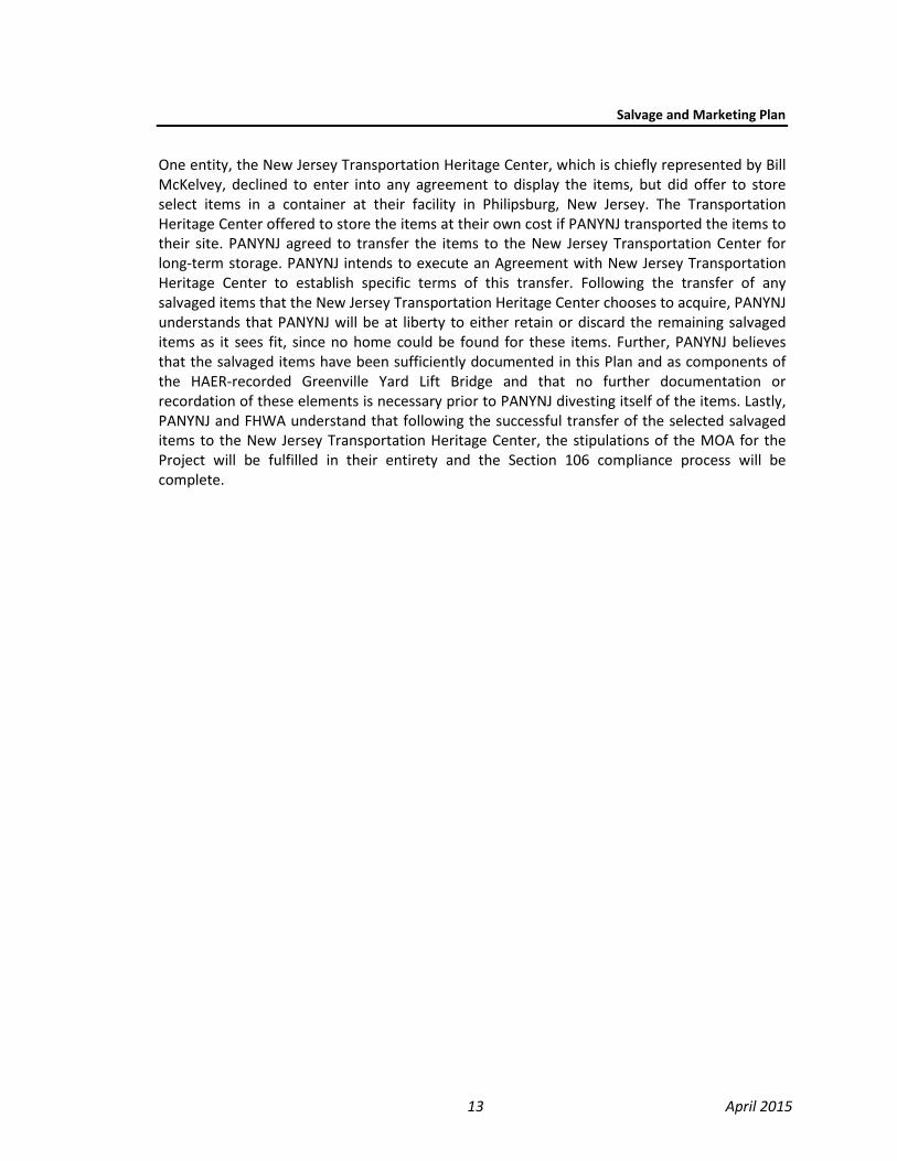
Salvage and Marketing Plan
13 April 2015
One entity, the New Jersey Transportation Heritage Center, which is chiefly represented by BillMcKelvey, declined to enter into any agreement to display the items, but did offer to storeselect items in a container at their facility in Philipsburg, New Jersey. The TransportationHeritage Center offered to store the items at their own cost if PANYNJ transported the items totheir site. PANYNJ agreed to transfer the items to the New Jersey Transportation Center forlong-term storage. PANYNJ intends to execute an Agreement with New Jersey TransportationHeritage Center to establish specific terms of this transfer. Following the transfer of anysalvaged items that the New Jersey Transportation Heritage Center chooses to acquire, PANYNJunderstands that PANYNJ will be at liberty to either retain or discard the remaining salvageditems as it sees fit, since no home could be found for these items. Further, PANYNJ believesthat the salvaged items have been sufficiently documented in this Plan and as components ofthe HAER-recorded Greenville Yard Lift Bridge and that no further documentation orrecordation of these elements is necessary prior to PANYNJ divesting itself of the items. Lastly,PANYNJ and FHWA understand that following the successful transfer of the selected salvageditems to the New Jersey Transportation Heritage Center, the stipulations of the MOA for theProject will be fulfilled in their entirety and the Section 106 compliance process will becomplete.
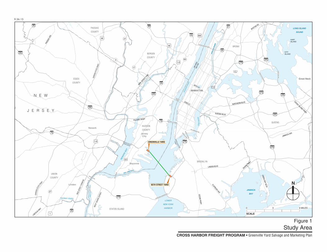
CITYISLAND
HARTISLAND
ESSEX
COUNTY
PASSAIC
COUNTY
BERGEN
COUNTY
UNION
COUNTY
HUDSON
COUNTY
Bayonne
JerseyCity
Newark
Linden
Great NeckGreat Neck
MANHATTANMANHATTAN
QUEENS
JAMAICA
BAY
JAMAICA
BAY
LONG ISLAND
SOUND
LONG ISLAND
SOUND
LOWER
NEW YORK
HARBOR
BROOKLYN
STATEN ISLAND
BRONX
N E W
J E R S E Y
NEW
JER
SEY
NEW
YO
RK
HU
DS
ON
RIV
ER
NEW
AR
K B
AY
KILL VAN KULL
KILL VAN KULL
AR
THU
R K
ILL
RAHWAY RIVERE
AS
T R
IVE
R
WARDSISLAND
HA
RLE
M R
IVER
HA
RLE
M R
IVER
HUNT'SPOINT
GEORGE WASHINGTON BR.
TUNNEL
LINCOLN
TUNNEL
HOLLAND
BROO
KLYN BR.
MA
NH
ATTA
N B
R.
WILLIAMSBURG BR.
BR
ON
X W
HITE
STO
NE
BR
.
TH
RO
GS
NE
CK
BR
.
GOETHALS BR.
LEHIGH VALLEYDRAW BRIDGE
BR
OO
KLY
N B
ATTER
Y
TUN
NE
L
VERRAZANO NARROWS BR.
BA
YO
NN
E B
R.
42ND ST.
86TH ST.
WES
T SH
ORE
EXPW
Y.
280
280
278
278
80 80
78
95
95
95
95
87
78
3
21
27
63
17
495
495
678
678295
278695
501
46
46
1
1-9
1-9
9WGA
RDEN
STA
TE PK
WY.
NEW
JERS
EY TU
RNPI
KE
NORTHERN BLVD
SHORE PKWY
CROSS ISLAND PKWY
LINDEN BLVD
FLATBUSH AVE
JAMAICA AVE
QUEENS BLVD
BOSTON RD
PASS
AIC
AVE
PULASKI SKWY
CROSS BAY BLVD
LINCOLN
HWY
NEW JE
RSEY TP
KE
OCEAN PKWY
GARD
EN S
TATE
PKW
Y.
65TH STREET YARD
GREENVILLE YARD
N
SCALE
0 3 6 MILES
Figure 1Study Area
9.26.13
CROSS HARBOR FREIGHT PROGRAM • Greenville Yard Salvage and Marketing Plan
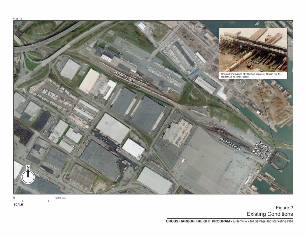
EXISTING TRACK
EXISTING TRACK
BRIDGE 9
BRIDGE 9BRIDGE 10
BRIDGE 10BRIDGE 11
BRIDGE 11BRIDGE 12
BRIDGE 12
EXISTING TRACK
EXISTING TRACK
9.26.13
CROSS HARBOR FREIGHT PROGRAM • Greenville Yard Salvage and Marketing Plan
Figure 2Existing Conditions
N
SCALE
0 1000 FEET
Undated photograph of lift bridge structure. Bridge No. 13,far right, is no longer extant
Figure 3a
9.26.13
NYNJR Storm Sandy Damage
During Storm Sandy SurgeBefore Storm Sand Surge
After Storm Sandy Surge - Barge Impact AreaAfter Storm Sandy Surge
31
42
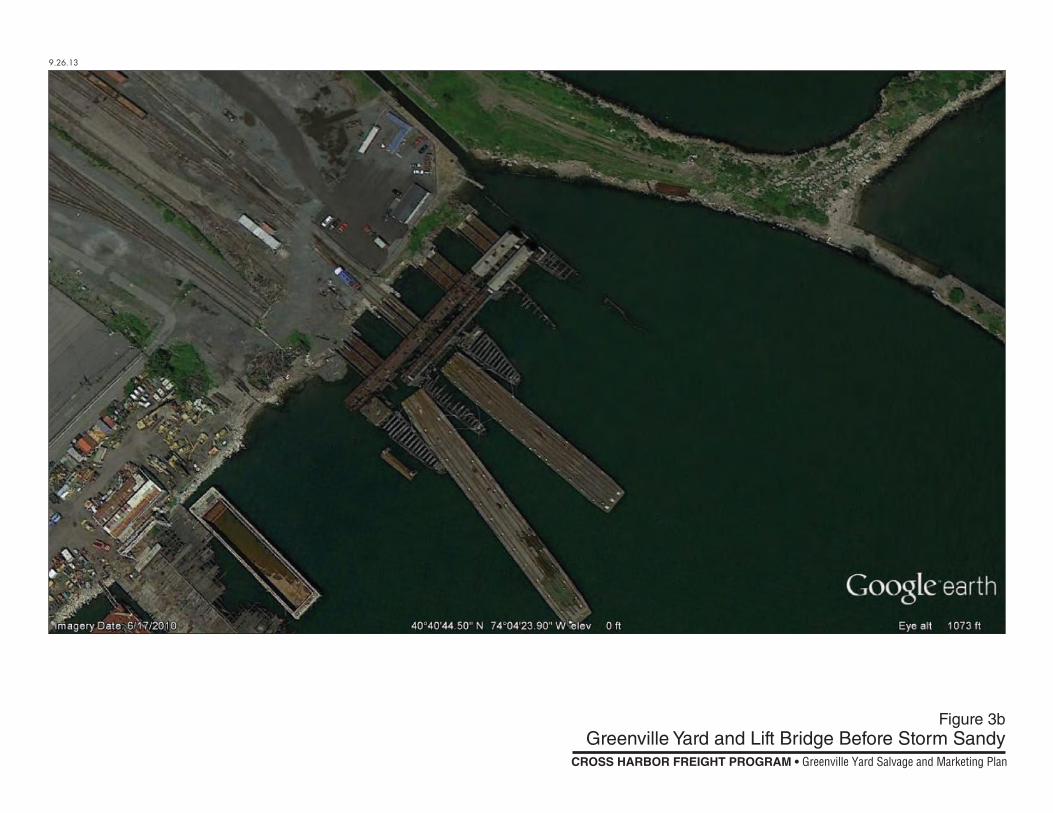
Figure 3b
9.26.13
Greenville Yard and Lift Bridge Before Storm Sandy
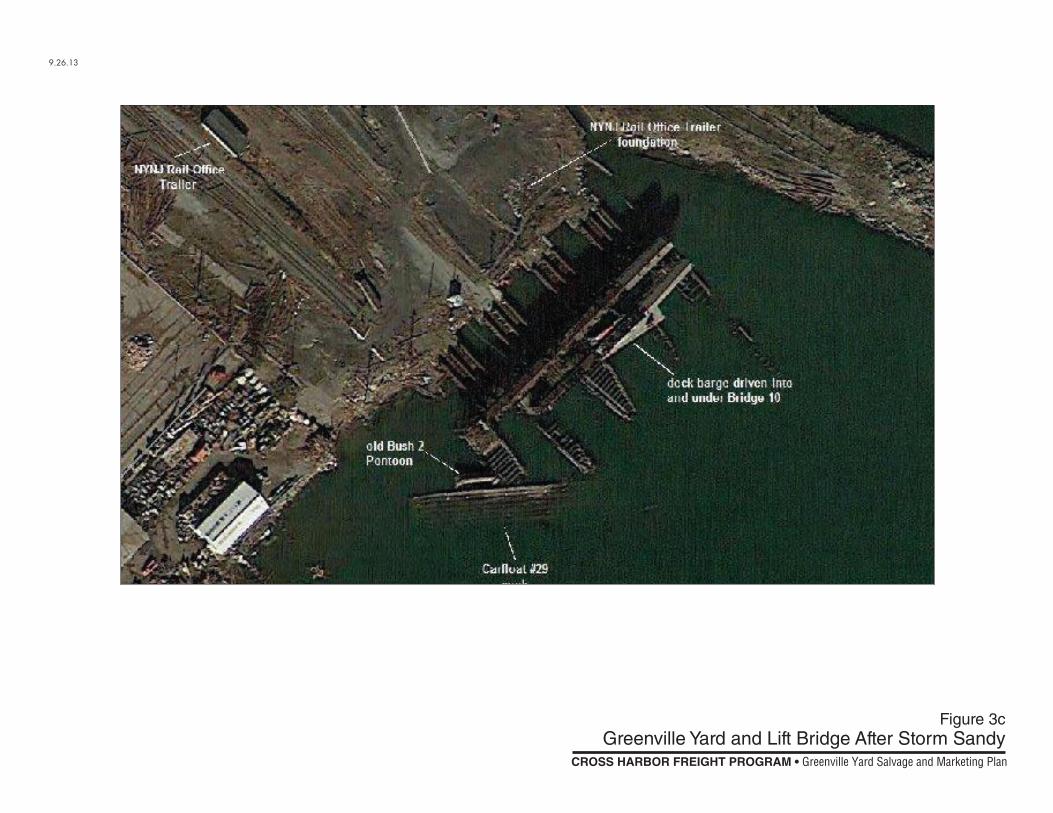
Figure 3c
9.26.13
Greenville Yard and Lift Bridge After Storm Sandy
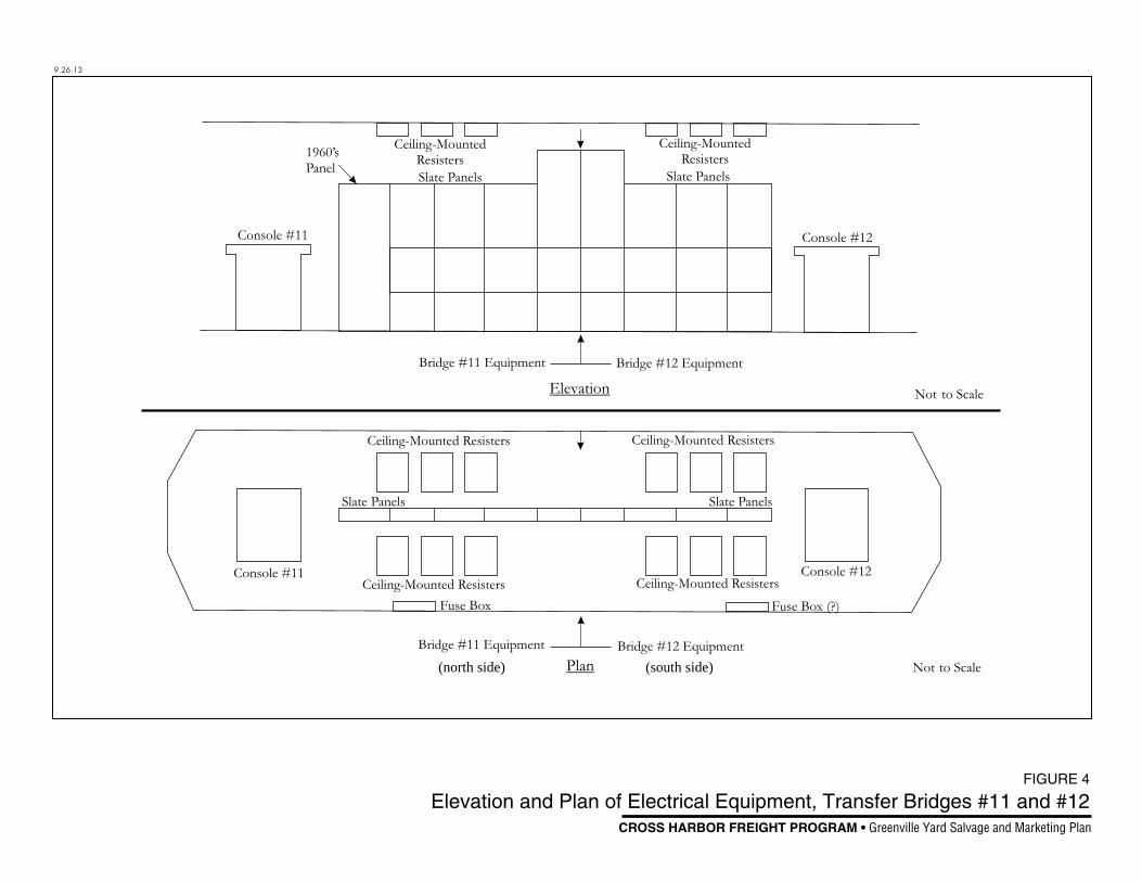
(north side) (south side)
9.26.13
FIGURE 4
Elevation and Plan of Electrical Equipment, Transfer Bridges #11 and #12CROSS HARBOR FREIGHT PROGRAM • Greenville Yard Salvage and Marketing Plan
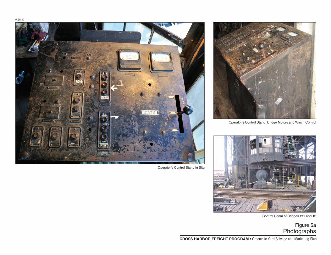
Figure 5aPhotographs
9.26.13
Control Room of Bridges #11 and 12
Operator’s Control Stand in Situ
Operator’s Control Stand, Bridge Motors and Winch Control
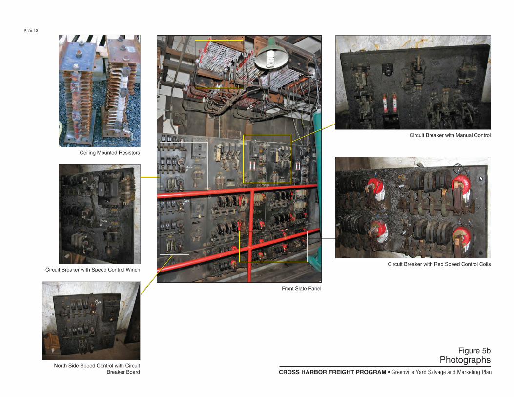
Figure 5bPhotographs
9.26.13
Circuit Breaker with Red Speed Control Coils
Front Slate Panel
Ceiling Mounted Resistors
North Side Speed Control with Circuit Breaker Board
Circuit Breaker with Speed Control Winch
Circuit Breaker with Manual Control
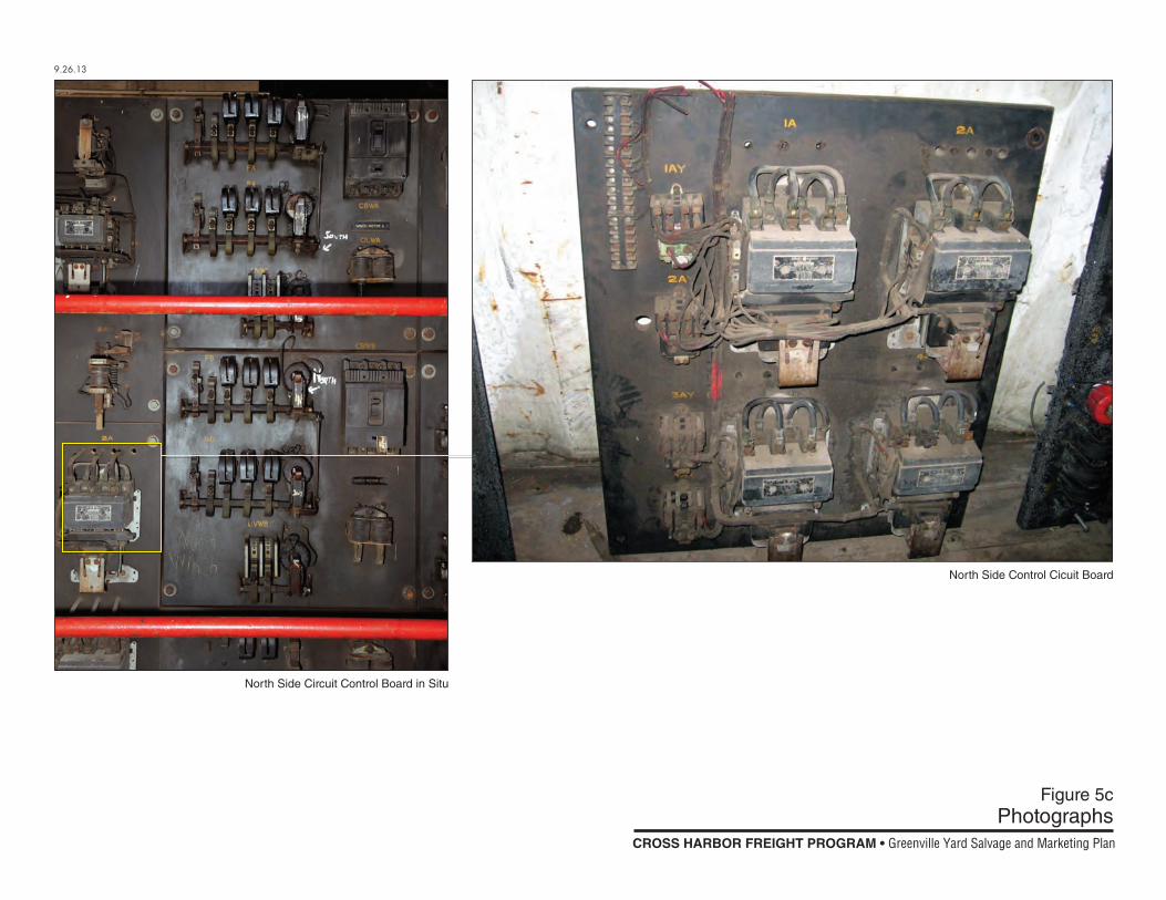
Figure 5cPhotographs
9.26.13
North Side Circuit Control Board in Situ
North Side Control Cicuit Board
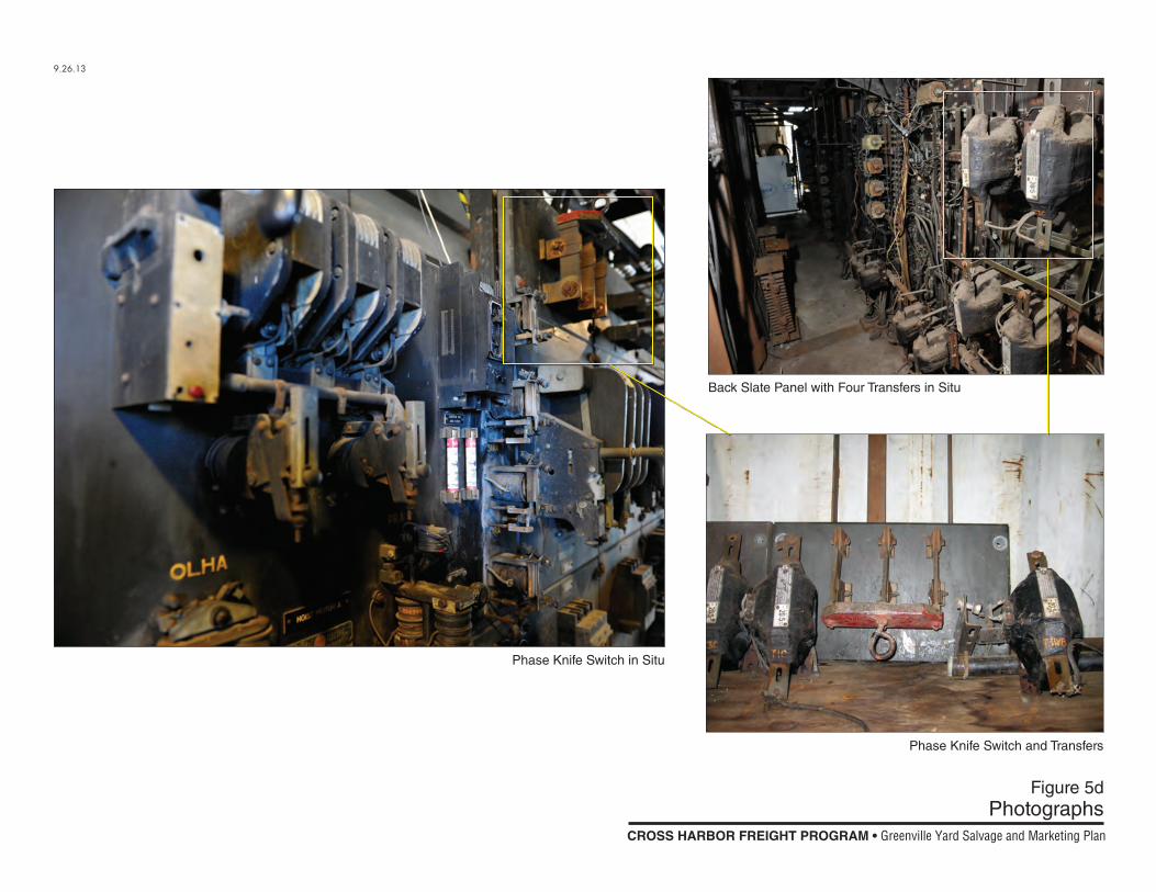
Figure 5dPhotographs
9.26.13
Phase Knife Switch in Situ
Phase Knife Switch and Transfers
Back Slate Panel with Four Transfers in Situ
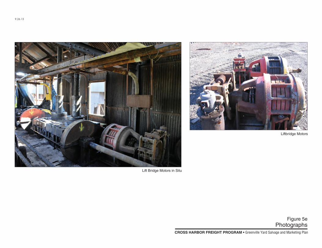
Figure 5ePhotographs
9.26.13
Liftbridge Motors
Lift Bridge Motors in Situ