Embed Size (px)
Citation preview

APPENDIX F
1830 Vernon Street, Suite 7 • Roseville, CA 95678 • 916-742-5096 • www.ACEqc.com Copyrighted © 2017 by ACE Quality Control, Inc. Intellectual Property. All rights reserved.
TABLE OF CONTENTS INTRODUCTION ............................................................................................................................................... 3
PURPOSE AND SCOPE OF STUDY .............................................................................................................. 3 PROPOSED PROJECT INFORMATION ........................................................................................................ 3
FINDINGS............................................................................................................................................................ 4 SITE DESCRIPTION ....................................................................................................................................... 4 GENERALIZED EARTH MATERIAL CONDITIONS .................................................................................. 4 GROUNDWATER ........................................................................................................................................... 5 GENERALIZED GEOLOGY ........................................................................................................................... 5 SITE SPECIFIC GEOLOGIC ASSESSMENT ................................................................................................. 6 PRIMARY SEISMIC HAZARDS .................................................................................................................... 6
CONCLUSIONS AND DISCUSSIONS ............................................................................................................. 8 SITE SUITABILITY AND GEOTECHNICAL CONSIDERATIONS ............................................................ 8 BEARING CAPABILITY ................................................................................................................................ 8 GROUNDWATER ........................................................................................................................................... 9 COMPRESSIBLE AND EXPANSIVE SOILS ................................................................................................. 9 MATERIALS SUITABILITY .......................................................................................................................... 9 POTENTIAL EXCAVATION DIFFICULTIES..............................................................................................10 POTENTIAL SLOPE STABILITY .................................................................................................................10 FOUNDATION TYPE ....................................................................................................................................10
RECOMMENDATIONS ...................................................................................................................................10 EARTHWORK ................................................................................................................................................10 CRITERIA FOR FOUNDATION DESIGN ....................................................................................................18 FLEXIBLE PAVEMENT SECTION ALTERNATIVES ................................................................................24
LIMITATIONS ...................................................................................................................................................28 REFERENCES ...................................................................................................................................................30 APPENDICES APPENDIX A GRAPHIC PRESENTATIONS – VICINITY AND EXPLORATIONS MAPS APPENDIX B FIELD EXPLORATION METHODS, LOGS, LEGEND APPENDIX C LABORATORY TESTING APPENDIX D GUIDE SPECIFICATIONS FOR EARTHWORK
1830 Vernon Street, Suite 7 • Roseville, CA 95678 • 916-742-5096 • www.ACEqc.com Copyrighted © 2016 by ACE Quality Control, Inc. Intellectual Property. All rights reserved.
PRELIMINARY GEOTECHNICAL ENGINEERING STUDY
BRADY RESIDENTIAL SUBDIVISION
NWC BRADY LANE AND VINEYARD ROAD ROSEVILLE, CALIFORNIA
INTRODUCTION
PURPOSE AND SCOPE OF STUDY
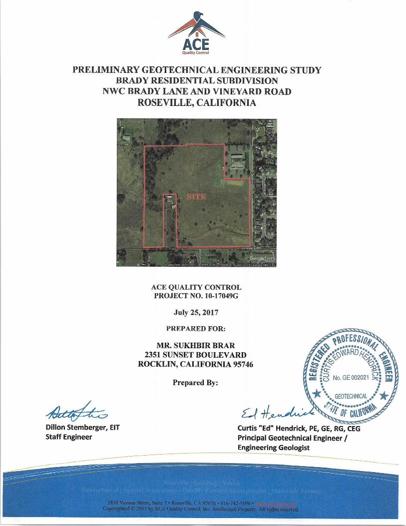
This report presents the results of our Preliminary Geotechnical Engineering Study for the proposed new
residential subdivision to be located at the above referenced site and as shown on the appended Location
Plan (Figure 1, Appendix A). The purpose of the study was to evaluate the general conditions of the
earth materials at the site in order to provide conclusions and recommendations related to the
geotechnical aspects of the project as discussed in our proposal / agreement dated May 15, 2017.
The scope of our work included exploring the general subsurface conditions, performing soil mechanics
laboratory tests, and determining soil parameters for earth grading, foundation design, lateral resistance,
floor slab-on-grade and pavement support, and expansive soil conditions, structural pavement support
and material thicknesses, and evaluating potential for soil liquefaction. Site specific geologic hazards
assessment (including naturally occurring asbestos – NOA) is not a part of our scope of work.
The attached Appendices contain further information including graphic presentations (Location Plan and
Map of Explorations -- Appendix A); field exploration procedures, legend and logs of subsurface
explorations (Appendix B); laboratory testing and procedures used (Appendix C); and, Guide
Specifications for Earthwork (Appendix D).
PROPOSED PROJECT INFORMATION The project is proposed on a +/- 35-acre parcel located at the northwestern corner of Brady Lane and
Vineyard Road in Roseville, California (the subject site). The project will include removing vegetation
(including designated trees) that are in the proposed new construction area, designing and constructing
approximately 86 new residential homes, new underground utilities, paved entry and connecting roads,
Project No. 10-17049G July 25, 2017 Preliminary Geotechnical Engineering Study
Proposed Brady Residential Subdivision Brady Lane and Vineyard Road, Roseville, CA
Page 4
1830 Vernon Street, Suite 7 • Roseville, CA 95678 • 916-742-5096 • www.ACEqc.com Copyrighted © 2017 by ACE Quality Control, Inc. Intellectual Property. All rights reserved.
parking and sidewalks. Cutting / filling on the order of 5 - 10 feet is anticipated, but the grading plans
were not available for review.
FINDINGS
SITE DESCRIPTION At the time of our field exploration, June 13, 2017, the parcel was bounded by Brady Lane to the east,
undeveloped parcels to the west and north, and Vineyard Road to the south. A church occupied a parcel
at the northeastern segment of the site. An occupied rectangular parcel (not a part of the subject site)
extended northerly into the southwestern segment of the property from Vineyard Road to about the
west-central area. The overall topography of the site was generally gently undulating.
The parcel was undeveloped and densely overgrown with weeds. Numerous trees lined a seasonal swale
that trended northerly to southerly in the western area of the parcel. Trees were scattered on the
remainder of the property. Relatively smaller swales trended easterly to westerly to the western larger
swale. An approximately 3 to 4 feet deep ditch trended westerly from Brady Lane through the
southeastern segment of the site to the swale on the rectangular parcel.
As part of our project site exploration, historical Google Earth aerial imagery was used to identify any
possible past activities on the subject site that are no longer visible. Plug dumped fill was noticeable on
7/2015 and 11/2015 photographs, but the fill appeared to have been either been removed or spread out
on a 7/2016 photograph. Photographs dating back to 1993 indicated that some grading had occurred on
the site along the sides of the Church’s parcel to the northeast, and was most obvious on the southern
side of that parcel. It is not clear if or where on the property other undocumented fill might be present.
GENERALIZED EARTH MATERIAL CONDITIONS As shown on the Test Borings Logs (Figure 2, Appendix B), the subsurface earth material conditions
varied slightly throughout the site and with depth. The soil encountered in the exploratory borings was
mainly medium dense to very dense, brown and brown with red and gray discolorations, moist, silty
SAND with variable gravel (Unified Soil Classification: SM) and well graded SAND (SW) to maximum
depths explored of approximately 21-1/2 feet below existing ground surface (egs). Some lenses of
Project No. 10-17049G July 25, 2017 Preliminary Geotechnical Engineering Study
Proposed Brady Residential Subdivision Brady Lane and Vineyard Road, Roseville, CA
Page 5
1830 Vernon Street, Suite 7 • Roseville, CA 95678 • 916-742-5096 • www.ACEqc.com Copyrighted © 2017 by ACE Quality Control, Inc. Intellectual Property. All rights reserved.
dense, brown, moist, SILT (Unified Soil Classification: ML) were encountered at variable depths and
thicknesses in some of the explorations.
Since the earth material profile is generalized, the reader is advised to consult the Explorations Logs
contained in Appendix B, if the earth material conditions at a specific depth and location are desired.
The logs contain a more detailed earth material description regarding color, earth material type, and
Unified Soil Classification System (USCS) symbol.
It should be noted that earth material conditions cannot be fully determined by exploratory borings and
earth material sampling. Hence, unexpected earth material conditions might be encountered during
construction. If earth material deposits are encountered during construction which vary substantially
from materials encountered during the investigation, then appropriate recommendations will be needed
during construction. Therefore, we suggest a contingency fund for additional expenditures that might
have to be made due to unforeseen conditions.
GROUNDWATER Observations of groundwater conditions were made during the excavation of our exploratory borings at
the time of field exploration. Free groundwater was not observed in borings B3 and B7. Free
groundwater was encountered in the other borings during our exploration at approximate depths below
estimated ground surface ranging from 13 to 21 feet. Please reference the Explorations Logs contained
in Appendix B, if the approximate depths to free groundwater are desired for individual borings.
Groundwater levels can fluctuate on a seasonal basis due to changes in precipitation, irrigation,
pumping, etc. Based on site topography and the time period our investigation was performed,
groundwater levels might change. However, excavations below perched groundwater (if encountered)
might be impacted by seepage; therefore, we recommend grading and utility excavations be performed
during dry-season when groundwater levels are lowest.
GENERALIZED GEOLOGY The site is located within California's Great Valley Geomorphic Province, a geologically young, large,
flat-lying alluvial plain in the central portion of California. It is 40 to 60 miles (60 to 100 km) wide and
stretches approximately 450 miles (720 km) from north-northwest to south-southeast, inland from and
Project No. 10-17049G July 25, 2017 Preliminary Geotechnical Engineering Study
Proposed Brady Residential Subdivision Brady Lane and Vineyard Road, Roseville, CA
Page 6
1830 Vernon Street, Suite 7 • Roseville, CA 95678 • 916-742-5096 • www.ACEqc.com Copyrighted © 2017 by ACE Quality Control, Inc. Intellectual Property. All rights reserved.
parallel to the Pacific Ocean Coast Ranges to the west and Sierra Nevada Mountains to the east. The
Great Valley has been filled with hundreds to thousands of feet of eroded sediments, ranging in age from
Pleistocene to Holocene. Relatively recent alluvial deposits generally consist of poorly sorted silts, fine
sands and clays with less extensive lenses of medium to coarse grained sands and gravel.
The native earth materials underlying the site are considered to be alluvial materials and consistent with
the earth materials discovered in the explorations. Based on our review of readily available published
geologic literature/maps (CGS Geologic Map 1A “Geologic Map of the Sacramento Quadrangle”, third
printing 2010; scale 1:250,000) the site is mapped to be underlain by Pleistocene alluvial deposits
consisting of gravels, sands, silts and clays of the Turlock Lake Formation. The total thickness of the
formation at this site was not determined and is beyond the scope of this study.
SITE SPECIFIC GEOLOGIC ASSESSMENT Not a part of this study.
PRIMARY SEISMIC HAZARDS
Fault Rupture Fault rupture hazards are important near active faults and tend to reoccur along the surface traces of
previous fault movements. The site is not located within an Alquist-Priolo Special Studies Zone and the
potential for fault rupture, damage from fault displacement, or fault movement directly below the site is
considered to be very low. However, the site is located within an area where shaking from earthquake
generated ground motion waves should be considered likely.
Seismic Shaking
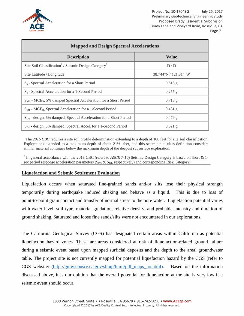
The mapped and design spectral response accelerations below presents seismic design criteria for the
subject project site obtained from the United States Geological Survey (USGS) website
(http://earthquake.usgs.gov/designmaps/us/application.php) with the USGS Seismic Design Maps
application. The values are based on data provided by the 2008 USGS National Seismic Hazard
Mapping Project and are for use with the 2013 California Building Code (CBC). The values for spectral
response accelerations reference with a risk category of I or II or III.
Project No. 10-17049G July 25, 2017 Preliminary Geotechnical Engineering Study
Proposed Brady Residential Subdivision Brady Lane and Vineyard Road, Roseville, CA
Page 7
1830 Vernon Street, Suite 7 • Roseville, CA 95678 • 916-742-5096 • www.ACEqc.com Copyrighted © 2017 by ACE Quality Control, Inc. Intellectual Property. All rights reserved.
Mapped and Design Spectral Accelerations
Description Value
Site Soil Classification1 / Seismic Design Category2 D / D
Site Latitude / Longitude 38.744°N / 121.314°W
Ss - Spectral Acceleration for a Short Period 0.518 g
S1 - Spectral Acceleration for a 1-Second Period 0.255 g
SMS - MCER, 5% damped Spectral Acceleration for a Short Period 0.718 g
SM1 - MCER, Spectral Acceleration for a 1-Second Period 0.481 g
SDS - design, 5% damped, Spectral Acceleration for a Short Period 0.479 g
SD1 - design, 5% damped, Spectral Accel. for a 1-Second Period 0.321 g
1 The 2016 CBC requires a site soil profile determination extending to a depth of 100 feet for site soil classification. Explorations extended to a maximum depth of about 21½ feet, and this seismic site class definition considers similar material continues below the maximum depth of the deepest subsurface exploration. 2 In general accordance with the 2016 CBC (refers to ASCE 7-10) Seismic Design Category is based on short & 1-sec period response acceleration parameters (SDS & SD1, respectively) and corresponding Risk Category.
Liquefaction and Seismic Settlement Evaluation Liquefaction occurs when saturated fine-grained sands and/or silts lose their physical strength
temporarily during earthquake induced shaking and behave as a liquid. This is due to loss of
point-to-point grain contact and transfer of normal stress to the pore water. Liquefaction potential varies
with water level, soil type, material gradation, relative density, and probable intensity and duration of
ground shaking. Saturated and loose fine sands/silts were not encountered in our explorations.
The California Geological Survey (CGS) has designated certain areas within California as potential
liquefaction hazard zones. These are areas considered at risk of liquefaction-related ground failure
during a seismic event based upon mapped surficial deposits and the depth to the areal groundwater
table. The project site is not currently mapped for potential liquefaction hazard by the CGS (refer to
CGS website: (http://gmw.consrv.ca.gov/shmp/html/pdf_maps_no.html). Based on the information
discussed above, it is our opinion that the overall potential for liquefaction at the site is very low if a
seismic event should occur.
Project No. 10-17049G July 25, 2017 Preliminary Geotechnical Engineering Study
Proposed Brady Residential Subdivision Brady Lane and Vineyard Road, Roseville, CA
Page 8
1830 Vernon Street, Suite 7 • Roseville, CA 95678 • 916-742-5096 • www.ACEqc.com Copyrighted © 2017 by ACE Quality Control, Inc. Intellectual Property. All rights reserved.
Earthquake Induced Landsliding Based on information available on the California Geological Survey (CGS) website the subject site is
not currently within a State of California Seismic Hazard Zone for seismically induced landsliding. In
addition, the main site area is relatively gently sloping; and, the slope on the north end of the property
does not have any indications of historic slumping. Therefore, seismically induced and/or other
landslides are not considered a significant hazard at the site.
Tsunamis and Seiche Evaluation The site is not located near large bodies of water and is approximately 120 to 150 feet above MSL.
Based on the geometry of the site, the potential for tsunami damage or damage caused by oscillatory
waves (Seiche) is not considered likely at the site.
CONCLUSIONS AND DISCUSSIONS
SITE SUITABILITY AND GEOTECHNICAL CONSIDERATIONS From a geotechnical standpoint, the site is considered suitable for the proposed construction provided
the conclusions and recommendations presented in this report are incorporated into the design and
construction of the project.
Geotechnical considerations that were evaluated by our office are discussed in the following sections of
this report.
BEARING CAPABILITY Field and laboratory tests show that the affirmed undisturbed, native earth materials encountered at the
boring locations are competent for support of the proposed construction. Any loose, wet, soft soils or
disturbed soils (including undocumented fill) that are present at the time of construction are not
considered stable and should not be utilized to directly support new structural elements without first
being overexcavated and then reworked as engineered fill (if deemed suitable); or, placed outside the
proposed improvements.
Project No. 10-17049G July 25, 2017 Preliminary Geotechnical Engineering Study
Proposed Brady Residential Subdivision Brady Lane and Vineyard Road, Roseville, CA
Page 9
1830 Vernon Street, Suite 7 • Roseville, CA 95678 • 916-742-5096 • www.ACEqc.com Copyrighted © 2017 by ACE Quality Control, Inc. Intellectual Property. All rights reserved.
Engineered fill, composed of approved materials placed and compacted according to the following
recommendations, are considered competent for support of low to moderate loading increases.
GROUNDWATER Free groundwater was encountered in multiple test borings at approximate depths of 13 to 21 feet below
the estimated ground surface. In addition, there is potential that shallow groundwater might be
encountered in low lying areas and intermittent swales. It is our opinion that groundwater should not
have significant impact on the proposed design or construction. However, groundwater levels at the site
might be higher during the winter and spring months. Depending on the depth of utilities, there might be
some impact on trenching during those seasons. In addition, if the uppermost soils should become
saturated, then this condition could impede or delay grading operations.
COMPRESSIBLE AND EXPANSIVE SOILS Compressible materials consisting of surficial organic material, loose soils, undocumented fills, debris,
rubble, rubbish, etc., are considered unsuitable materials for support of proposed structures. Such
materials can differentially settle. We consider that all loose/undocumented fill and/or disturbed soil
materials that might be encountered during the earthwork construction should be removed. Those earth
materials deemed suitable for re-use as engineered fill could be stockpiled. If the unsuitable materials
are not removed, then special foundation systems should be designed to account for the potential
settlements. In addition, in areas where loose, wet soils are removed as well as areas where trees have
been or will be cleared, remedial grading will also be required to remove the loose soils and ensure the
removal of the entire tree root systems. It is our experience that the granular soils have relatively low
plasticity, and are considered to have very low potential for expansion.
Native undisturbed soil and/or engineered fill, composed of approved granular materials placed and
compacted according to those discussed in the recommendations section, below, are considered
competent for support of low to moderate loading increases anticipated for this project.
MATERIALS SUITABILITY On-site soils similar to those encountered in the test borings are generally considered suitable for re-use
as engineered fill provided the materials are processed to remove excessive moisture, rubble, rubbish,
Project No. 10-17049G July 25, 2017 Preliminary Geotechnical Engineering Study
Proposed Brady Residential Subdivision Brady Lane and Vineyard Road, Roseville, CA
Page 10
1830 Vernon Street, Suite 7 • Roseville, CA 95678 • 916-742-5096 • www.ACEqc.com Copyrighted © 2017 by ACE Quality Control, Inc. Intellectual Property. All rights reserved.
oversize materials, significant organic matter, highly plastic soil (if such should be encountered), or any
other substance deemed unsuitable.
POTENTIAL EXCAVATION DIFFICULTIES It is anticipated that the soil materials at the site can be readily moved by conventional earth moving
equipment.
POTENTIAL SLOPE STABILITY No landslides, slumps, or other indications of slope instabilities were observed in the general area during
our field reconnaissance. We conclude that the natural relatively shallow slopes present within the site
area are stable under the conditions observed.
FOUNDATION TYPE A number of possible foundation alternatives are available to support the proposed buildings. Due to the
relatively low to moderate loads anticipated and in accordance with current construction practices, the
foundation system considered appropriate for the structures at this site is one consisting of conventional
spread footings supported either on two or more feet of non-expansive engineered fill and/or native,
undisturbed, medium dense to very dense soil. Design criteria for these footings are discussed in the
following Recommendations Section, below.
RECOMMENDATIONS
EARTHWORK General Earthwork specifications which may be used as a guide in the preparation of contract documents for site
grading are included in Appendix D. However, recommendations in the text of this report supersede
those presented in Appendix D. The conclusions and recommendations contained in this report
should be incorporated into the guide specifications. All recommendations could require
modifications based on conditions encountered during grading. In addition, changes in the locations of
the proposed structures and pavements could also necessitate modifications to the recommendations
Project No. 10-17049G July 25, 2017 Preliminary Geotechnical Engineering Study
Proposed Brady Residential Subdivision Brady Lane and Vineyard Road, Roseville, CA
Page 11
1830 Vernon Street, Suite 7 • Roseville, CA 95678 • 916-742-5096 • www.ACEqc.com Copyrighted © 2017 by ACE Quality Control, Inc. Intellectual Property. All rights reserved.
provided herein. Recommendations for the design and construction of the proposed structures and
associated improvements are included below.
Site Clearing and Stripping We recommend removal of any unstable or unsuitable materials such as soils disturbed during removal
of loose soils, undocumented fills and / or other hidden features, trees, or otherwise unsuitable/unstable
materials, from the areas where new structures, pavements, retaining walls, flatwork, fill slopes, etc., are
planned. The excavated unstable soils could be evaluated for reuse as engineered fill. The resulting
excavation(s) should be prepared and filled to subgrade level with engineered fill as discussed in the
following sections.
The building pads and pavement areas should be cleared of all obstructions or unsuitable materials,
including all undocumented fill and/or loose, wet or disturbed soil, rubble, rubbish, vegetation, and any
buried utility lines to be removed. Tree root bowls due to tree removal should be cleared of all large
roots and loose soils. Any cisterns, septic tanks, leach fields, water wells, etcetera that might be
encountered and are to be abandoned should be removed.
Excavations resulting from the removal of unsuitable materials and/or loose soils should be cleared to
expose firm, stable material and backfilled with approved earth materials compacted to the requirements
given below under compaction. Utilities that extend into the construction area and are scheduled to be
abandoned should be properly capped at the perimeter of the construction zone or moved as directed in
the plans. The surface of the resulting excavations should be scarified to a depth of 8 inches and
recompacted to 95 percent relative compaction per ASTM D1557 at moisture content to between one to
three percent above optimum moisture content.
The building pad is considered to extend laterally away from (outside of) all perimeter footing/building
edges at least five (5) feet in plan view. The pavement area is considered to extend at least three (3) feet
beyond the perimeter edges of the structural pavement section.
In conjunction with clearing, the building pad and pavement areas should be stripped to sufficient depth
to remove all organic laden topsoil. The actual stripping depth should be determined by our
representative at the time of construction. The cleared and stripped materials should be removed from
the site or stockpiled for possible use as landscape materials.
Project No. 10-17049G July 25, 2017 Preliminary Geotechnical Engineering Study
Proposed Brady Residential Subdivision Brady Lane and Vineyard Road, Roseville, CA
Page 12
1830 Vernon Street, Suite 7 • Roseville, CA 95678 • 916-742-5096 • www.ACEqc.com Copyrighted © 2017 by ACE Quality Control, Inc. Intellectual Property. All rights reserved.
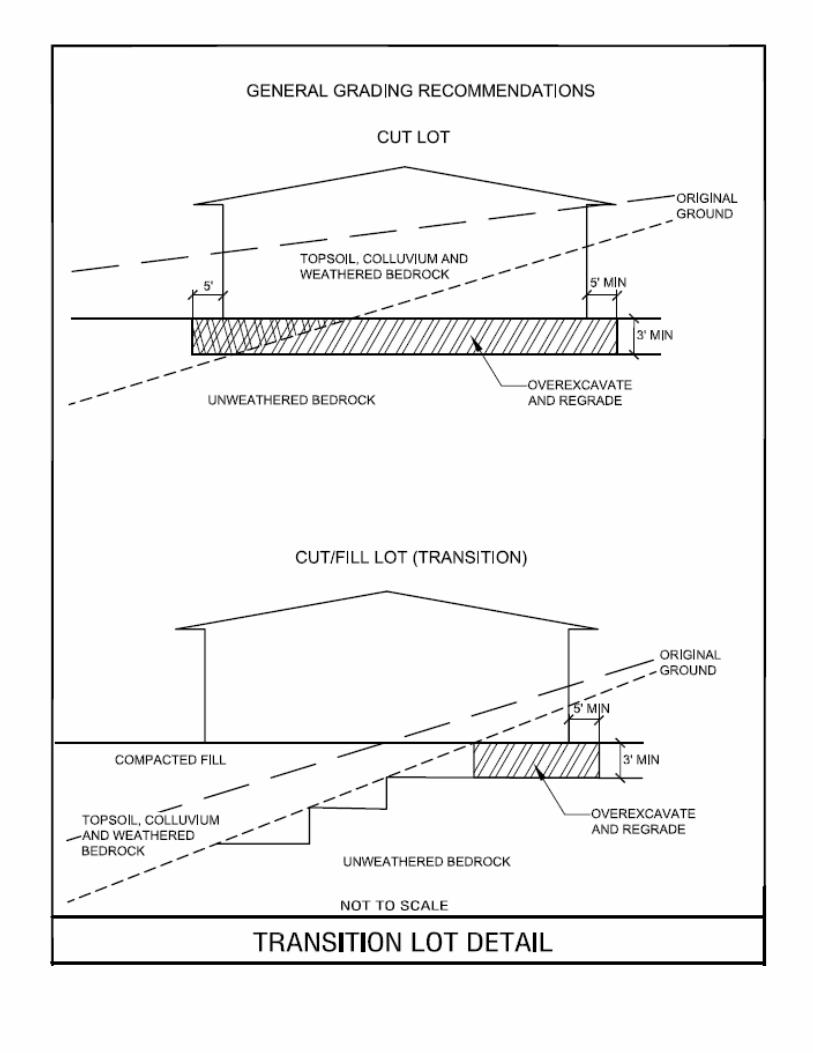
Subgrade Preparation Once the construction areas have been cleared, any unsuitable soils over-excavated and any other
excavations made, then subgrades that will receive engineered fill, that are to be left at existing grade, or
that represent final subgrades achieved by excavation should be scarified to at least 8 inches. Suitability
of soils exposed in the bottom of all subgrades should be verified by an ACE special inspector during
site grading. Upon favorable review, exposed subgrades should be scarified and recompacted (in-place)
an additional 8 inches and/or prior to placing engineered fill materials to planned rough pad grade. The
loosened soils should be uniformly moisture conditioned to 1 to 3 percent over optimum and compacted
to at least 90 percent relative compaction per ASTM D 1557; in pavement subgrade areas, to at least 95
percent in the upper twelve inches. ACE’s special inspector should observe the recompacted subgrades
be proof-rolled with very heavy construction equipment (e.g., loaded water truck) in order to verify
subgrade soil stability. Inability to achieve the stated moisture content, compaction, or instability of the
subgrade materials could be used as further criteria for the removal of loose, wet or soft soils, or for the
need of special stabilizing measures.
If unanticipated unsuitable materials are encountered at subgrade such that they are unstable and/or
proper compaction cannot be obtained, then mitigation measures, such as overexcavations to remove
such material, would be recommended. In addition, construction equipment on saturated soils could
destabilize the earth materials, sometimes to several feet of depth, which might necessitate further
overexcavation and/or special stabilization.
An ACE special inspector should observe and approve the bottom of all overexcavations to confirm
adequate conditions have been reached and shall observe and approve the scarification, moisture
conditioning and recompaction of the excavated surfaces.
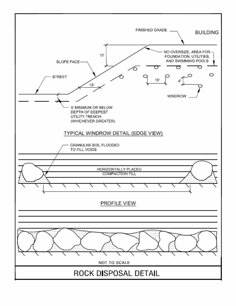
Material for Fill All fill materials should be inorganic soils free of vegetation, debris, and fragments larger than three
inches in size. Pea gravel or other similar non-cementitious, poorly-graded materials should not be used
as fill or backfill without the prior approval of the geotechnical engineer. Approved imported materials
or onsite fill materials may be used as fill material for general site grading, foundation backfill,
foundation areas, trench backfill, slab areas, and pavement areas.
Project No. 10-17049G July 25, 2017 Preliminary Geotechnical Engineering Study
Proposed Brady Residential Subdivision Brady Lane and Vineyard Road, Roseville, CA
Page 13
1830 Vernon Street, Suite 7 • Roseville, CA 95678 • 916-742-5096 • www.ACEqc.com Copyrighted © 2017 by ACE Quality Control, Inc. Intellectual Property. All rights reserved.
Soils from any source (on-site or off-site) for use as fill material within the proposed improvement areas
should conform to low volume change materials as indicated as follows: Percent Finer by Weight
Gradation (ASTM C 136) 3” ...............................................................................................................100 No. 4 Sieve ........................................................................................... 50 - 100 No. 200 Sieve ....................................................................................... 20 - 50 o Liquid Limit ....................................................................... 30 (max) o Plasticity Index ................................................................. 15 (max) o Maximum expansive index* .............................................. 30 (max) *ASTM D 4829
Engineered fill should be placed and compacted in horizontal lifts, using equipment and procedures that
will produce recommended moisture contents and densities throughout the lift. Fill lifts should not
exceed eight inches in loose thickness.
All fill materials that are pre-approved by this firm at least 48 hours in advance of grading are
considered suitable for use as fill. Earth materials from any source to be used for engineered fill should
be observed by our representative and samples obtained for laboratory testing (if required) at least four
days prior to any materials used for engineered fill.
In areas proposed for general fill not proposed to support improvements (e.g., buildings and pavements)
the materials to be re-used as engineered fill three feet or more below soil subgrade level should have an
Expansion Index not exceeding 50 (EI<50); not more than 35 percent passing a #200 sieve; do not
contain rocks or lumps greater than 8 inches in greatest dimension with not more than 35 percent larger
than 4 inches; and, which are pre-approved by this firm.
Fill Placement and Compaction Materials for engineered fill should be spread and compacted in lifts not exceeding 8 inches in
uncompacted thickness. Engineered fill placed at the site and subgrades requiring recompaction should
be uniformly compacted to 90 percent relative compaction in building areas, and to 95 percent relative
compaction in the upper two feet of pavement and flatwork areas, as determined by ASTM Test
Designation D 1557, or to the method as might be determined by an ACE special inspector. The
moisture content of engineered fill materials should be determined by ACE’s field representative based
upon the compaction characteristics of the earth material (typically 1 to 3 percent over optimum). ACE
Project No. 10-17049G July 25, 2017 Preliminary Geotechnical Engineering Study
Proposed Brady Residential Subdivision Brady Lane and Vineyard Road, Roseville, CA
Page 14
1830 Vernon Street, Suite 7 • Roseville, CA 95678 • 916-742-5096 • www.ACEqc.com Copyrighted © 2017 by ACE Quality Control, Inc. Intellectual Property. All rights reserved.
should continuously observe and test the grading and earthwork operations for this project. Such
observations and tests are essential to identify field conditions that differ from those predicted by this
investigation, to adjust these recommendations to actual field conditions encountered, and to verify that
the grading is in overall accordance with the recommendations presented in this report.
If construction proceeds during or shortly after the wet winter months, it may require time to dry the on-
site soils since their moisture content will probably be appreciably above the optimum. In addition, if
subgrade soils are wet at the time of construction, they could be rutted, loosened or otherwise disturbed
to several feet of depth by the construction equipment and require additional over-excavation and/or
stabilization.
Construction occurring in later summer or early fall (subsequent to on-site earth materials becoming dry)
may require substantial amounts of water to be added during earthwork operations to enable the
appropriate moisture content and compaction to be achieved.
Upon completion of filling and grading, care should be taken to maintain the subgrade moisture content
prior to construction of foundations, exterior flatwork/slabs and pavements. Construction traffic over
the completed subgrade should be avoided in order to prevent disturbance of subgrade soils. The site
should also be graded to prevent ponding of surface water on the prepared subgrades or in excavations.
If the subgrade consisting of engineered fill should become desiccated, saturated, or disturbed, the
affected material should be removed or these materials should be scarified, moisture conditioned, and
recompacted prior to construction.
The geotechnical engineer should be retained during the earthwork construction phase of the project to
observe earthwork and to perform necessary tests and observations during subgrade preparation,
backfilling of excavations to the completed subgrade, placement and compaction of engineered fills,
proof-rolling, backfilling of utility trenches, etc.
Trench Backfill Utility trenches should be backfilled with mechanically compacted fill placed in lifts not exceeding 8
inches in uncompacted thickness. Water content of the fill material should be adjusted (typically 1 to 3
percent over optimum) during the trench backfilling operations to obtain compaction. If on-site soil is

Project No. 10-17049G July 25, 2017 Preliminary Geotechnical Engineering Study
Proposed Brady Residential Subdivision Brady Lane and Vineyard Road, Roseville, CA
Page 15
1830 Vernon Street, Suite 7 • Roseville, CA 95678 • 916-742-5096 • www.ACEqc.com Copyrighted © 2017 by ACE Quality Control, Inc. Intellectual Property. All rights reserved.
used, the material should be compacted to at least 90 percent relative compaction. Imported sand could
also be used for backfilling trenches provided it is compacted to at least 95 percent relative compaction.
Utility trenches should be plugged with lean concrete wherever the utility line passes beneath the
perimeters of the structures. The plug should be at least one foot on either side of the perimeter of the
building perimeter footing and extend from the bottom of the building perimeter (e.g., foundation) to the
bottom of the trench.
Finish Grading and Drainage On-site soils are considered moderately susceptible to erosion where drainage concentrations occur.
Concentrated flowing water should be either dissipated or channeled to appropriate discharge facilities.
Appropriate erosion control measures should be provided, where applicable, by the general civil
engineer on his grading and/or winterization plan.
Positive surface gradients should be provided adjacent to the buildings and within pavement areas to
direct surface water away from the buildings and pavement for at least ten feet and toward suitable
discharge facilities. Ponding of surface water should not be allowed adjacent to the buildings or
pavement nor on top of pavement. Positive drainage should be provided during construction and
maintained throughout the life of the buildings. Infiltration of water into utility trenches or foundation
excavations should be prevented during construction. Backfill against footings, exterior walls, and in
utility and sprinkler line trenches should be well compacted and free of all construction debris to reduce
the possibility of moisture infiltration. We recommend a minimum horizontal setback distance of 10 feet
from the perimeter of any building and the high-water elevation of the nearest storm-water retention.
Downspouts, roof drains or scuppers should discharge into splash blocks or extensions when the ground
surface beneath such features is not protected by exterior slabs or paving. Sprinkler systems should not
be installed within 5 feet of foundation walls. Landscaped irrigation adjacent to the foundation system
should be minimized or eliminated.
All grades must provide effective drainage away from the building during and after construction. Water
permitted to pond next to the building can result in greater soil movements than those discussed in this
report. These greater movements can result in unacceptable differential floor slab movements, cracked
Project No. 10-17049G July 25, 2017 Preliminary Geotechnical Engineering Study
Proposed Brady Residential Subdivision Brady Lane and Vineyard Road, Roseville, CA
Page 16
1830 Vernon Street, Suite 7 • Roseville, CA 95678 • 916-742-5096 • www.ACEqc.com Copyrighted © 2017 by ACE Quality Control, Inc. Intellectual Property. All rights reserved.
slabs and walls, and roof leaks. Estimated movements described in this report are based on effective
drainage for the life of the structure and cannot be relied upon if effective drainage is not maintained.
Exposed ground should be sloped at a minimum 2 percent down and away from the building for at least
10 feet beyond the perimeter of the building or pavement. After building construction and landscaping,
we recommend verifying final grades to document that effective drainage has been achieved. Grades
around the structure should also be periodically inspected and adjusted as necessary, as part of the
structure’s maintenance program.
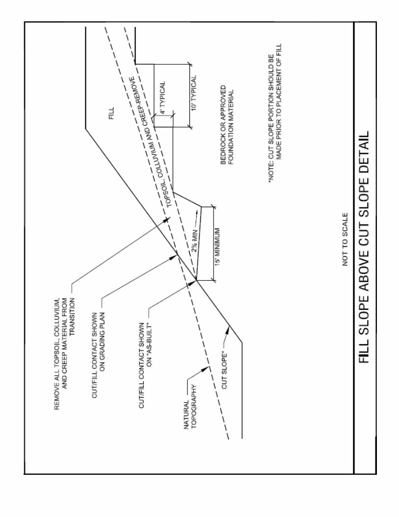
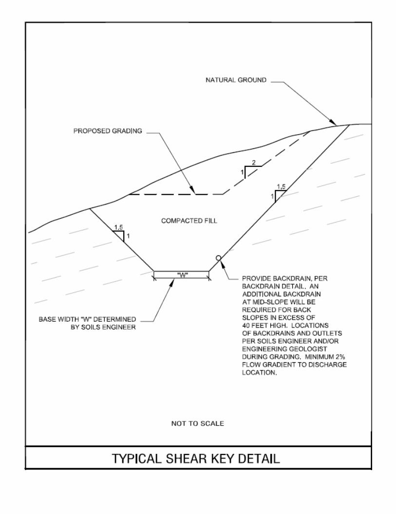
Slopes Permanent excavation and embankment slopes up to 15 feet of height in soil should be graded at an
inclination of 2 horizontal to 1 vertical (2h: 1v) or flatter. The crowns of all slopes should be
constructed so that surface run-off water is not allowed to flow over the faces of the slopes. All cut
slopes should be observed during grading by the Engineering Geologist to determine if any adverse
defects are present. If defects are observed, then additional study and/or recommendations would be
made at that time.
For construction slopes, the individual contractor(s) is/are responsible for designing and constructing
stable, temporary excavations as required to maintain stability of both the excavation sides and bottom.
Excavations should be sloped or shored in the interest of safety following local and federal regulations,
including current OSHA excavation and trench safety standards.
Earthwork Construction Considerations
At the time of our study, moisture contents of the surface and near-surface native soils ranged from
approximately 4 percent to 27 percent. Based on these moisture contents, some moisture conditioning
will likely be needed for the project. The soils may need to be dried by aeration during wet weather
conditions, or a chemical treatment, such as cement, lime, or kiln dust, may be needed to stabilize the
soil. Subgrade conditions may require a rock protective mat covering of exposed subgrades in order to
limit disturbance of the site soils as well as provide a stable base for construction equipment.
Although the exposed subgrades are anticipated to be relatively stable upon initial exposure, on site soils
may pump and unstable subgrade conditions could develop during general construction operations,
particularly if the soils are wetted and/or subjected to repetitive construction traffic. The use of light
Project No. 10-17049G July 25, 2017 Preliminary Geotechnical Engineering Study
Proposed Brady Residential Subdivision Brady Lane and Vineyard Road, Roseville, CA
Page 17
1830 Vernon Street, Suite 7 • Roseville, CA 95678 • 916-742-5096 • www.ACEqc.com Copyrighted © 2017 by ACE Quality Control, Inc. Intellectual Property. All rights reserved.
construction equipment would aid in reducing subgrade disturbance. The use of remotely operated
equipment, such as a backhoe, would be beneficial to perform cuts and reduce subgrade disturbance. If
unstable subgrade conditions develop, then stabilization measures will need to be employed. Upon
completion of filling and grading, care should be taken to maintain the subgrade moisture content prior
to construction of the floor slabs and pavements. Construction traffic over the completed subgrades
should be avoided to the extent practical. The site should also be graded to prevent ponding of surface
water on the prepared subgrades or in excavations. If the subgrade should become desiccated, saturated,
or disturbed, the affected material should be removed or these materials should be scarified, moisture
conditioned, and recompacted prior to floor slab and pavement construction.
We anticipate that site grading for concrete foundations, slab construction, pavements and utility
trenches can be performed with conventional earthmoving equipment. We emphasize the contractor is
responsible for designing and constructing stable, temporary excavations (including utility trenches) as
required to maintain stability of both the excavation sides and bottom and should be in accordance with
OSHA excavation and trench safety standards.
We recommend that the earthwork portion of this project be completed during extended periods of dry
weather if possible. If earthwork is completed during the wet season (typically November through May)
it may be necessary to take extra precautionary measures to protect subgrade soils. Wet season
earthwork may require additional mitigation measures beyond that which would be expected during the
drier summer and fall months. This could include diversion of surface runoff around exposed soils and
draining of ponded water on the site. Once subgrades are established, it may be necessary to protect the
exposed subgrade soils from construction traffic.
If unstable subgrade conditions develop during construction, suitable methods of stabilization will be
dependent upon factors such as schedule, weather, size of area to be stabilized, and the nature of the
instability. If soil stabilization is needed, ACE should be consulted to evaluate the situation as needed.
Construction Observation
As previously discussed, variations in subsurface conditions are possible and may be encountered during
construction. In order to permit correlation between the preliminary subsurface data obtained during
this investigation and the actual subsurface conditions encountered during construction, as well as affirm
Project No. 10-17049G July 25, 2017 Preliminary Geotechnical Engineering Study
Proposed Brady Residential Subdivision Brady Lane and Vineyard Road, Roseville, CA
Page 18
1830 Vernon Street, Suite 7 • Roseville, CA 95678 • 916-742-5096 • www.ACEqc.com Copyrighted © 2017 by ACE Quality Control, Inc. Intellectual Property. All rights reserved.
substantial conformance with the plans and specifications, a representative of this firm should be present
during all phases of the site earthwork to make tests and observations of the site preparation, selection of
satisfactory fill materials, proof-rolling, placement and compaction of controlled compacted fills,
backfilling of excavations to the completed subgrade, etc. Additionally, if lime treatment is needed, then
he should perform observations during mixing, remixing and compaction.
Any site earthwork performed without the presence of our representative will be entirely at the grading
contractor's and/or owner's risk and no responsibility for such operations will be accepted by our firm.
Sufficient notification (at least 48 hours) is necessary to assure that our work will coincide with the
construction schedule.
We emphasize the importance of ACE’s presence during the observation and testing of the
grading operations. ACE’s observation of the subsurface soil conditions, especially under the
loads imposed by construction equipment, is considered an extension of our investigation,
particularly within those areas away from the test borings.
Guide Specifications Earthwork guide specifications which may be used as a guide in the preparation of contract documents
for site grading are included in Appendix D. The conclusions and recommendations contained in
this report should be incorporated into the guide specifications.
CRITERIA FOR FOUNDATION DESIGN General An important factor in soils is a change in moisture content. The following is predicated on the soil
moisture beneath and within five feet of the building slabs being maintained in a uniform condition
during and after construction. Please be advised that over watering or under watering, types of plants
(trees should be a distance equal to at least their maximum height away from the slab), altering site
drainage, and etc., might be detrimental to the foundation and/or pavements. We suggest that automatic
timing devices be utilized on irrigation systems; however, provision should be made to interrupt the
normal watering cycle during and following periods of rainfall.

Project No. 10-17049G July 25, 2017 Preliminary Geotechnical Engineering Study
Proposed Brady Residential Subdivision Brady Lane and Vineyard Road, Roseville, CA
Page 19
1830 Vernon Street, Suite 7 • Roseville, CA 95678 • 916-742-5096 • www.ACEqc.com Copyrighted © 2017 by ACE Quality Control, Inc. Intellectual Property. All rights reserved.
Foundation Design Criteria Based on the field and laboratory information for this study, we recommend that the proposed buildings
and any retaining walls (up to 5 feet high) be supported upon isolated and/or continuous spread footings
that extend at least 12- or 18-inches below the building pad engineered soil surface or lowest abutting
engineered soil grade for one- or two-story structures, respectively. All foundations beneath the entire
structure should be founded on native, undisturbed soil and / or engineered fill. ACE’s geotechnical
engineer or his representative should observe earth material conditions exposed in foundation
excavations in order to confirm the adequacy for structural foundation bearing, confirm the
appropriateness of these recommendations, and to allow for an opportunity to provide additional
recommendations if deemed necessary. If the earth material conditions encountered differ significantly
from those presented in this report, then supplemental recommendations will be required.
Foundation dimensions and reinforcement should be based on allowable soil bearing value of 2,500
pounds per square foot (psf) for spread footings of at least 12-inches in width penetrating into and
embedded below rough pad bearing soil grade at least 12- or 18-inches for one- or two-story structures
(or equivalent), respectively.
Spread footing excavations that are deeper than the planned bottoms of the footing excavations could be
filled to the planned footing bottom elevation with either footing concrete or Controlled Low-Strength
Material (CLSM) per section 1803.5.9 of the 2013 CBC, with approval of the Geotechnical Engineer.
The CLSM should have at least 400 psi compressive strength at 28 days. The allowable foundation
bearing pressures apply to dead loads plus design live load conditions. The design bearing pressure may
be increased by one-third when considering total loads that include short duration wind or seismic
conditions. The weight of the foundation concrete below grade may be neglected in dead load
computations.
The allowable foundation bearing pressures apply to dead loads plus design live load conditions. The
design bearing pressure may be increased by one-third when considering total loads that include wind or
seismic conditions. The weight of the foundation concrete below grade may be neglected in dead load
computations.
Project No. 10-17049G July 25, 2017 Preliminary Geotechnical Engineering Study
Proposed Brady Residential Subdivision Brady Lane and Vineyard Road, Roseville, CA
Page 20
1830 Vernon Street, Suite 7 • Roseville, CA 95678 • 916-742-5096 • www.ACEqc.com Copyrighted © 2017 by ACE Quality Control, Inc. Intellectual Property. All rights reserved.
Footings should be proportioned to reduce differential foundation movement. Proportioning on the basis
of equal total settlement is recommended; however, proportioning to relative constant dead-load
pressure will reduce differential settlement between adjacent footings. Additional foundation
movements could occur if water, from any source, saturates the foundation soils; therefore, proper
drainage should be provided during construction and in the final design.
We recommend that all footings be reinforced as required by the structural engineer to provide structural
continuity, to permit strong spanning of local irregularities and to be rigid enough to accommodate
potential differential movements estimated at about one-half inch over 20 linear feet. The use of joints at
openings, or other discontinuities, especially in masonry walls, is recommended. Based on the
conditions observed at the site, the total structure settlement is expected to be on the order of one inch
for static compression. Dynamic settlement due to an earthquake event is not expected to adversely
affect the proposed improvements. The foundation settlement will depend upon the variations within
the subsurface soil profile, the structural loading conditions, the embedment depth of the footings, the
thickness of compacted fill, and the quality of the earthwork operations. We estimate that total and
differential settlements should not exceed the predicted values, provided that the foundations are
designed and constructed as recommended herein, and essentially no changes occur in water contents of
foundation soils. Additional foundation movements could occur if water from any source infiltrates the
foundation soils; therefore, proper drainage should be provided in the final design and during
construction. All foundations should be designed by the project structural engineer. The foundation excavations should be clean (i.e., free of all loose slough) and moist prior to placing
steel and concrete. Foundation excavations should be maintained at moisture contents of between 1 to 3
percent over optimum moisture content just prior to foundation concrete placement. The concrete for the
foundation should not be placed against a dry excavation surface.
The base of all foundation excavations should be free of water, loose soil, and gravel prior to placing
concrete. Concrete should be placed soon after excavating and placement of engineered fill (and lime
treatment, if needed) to reduce bearing soil disturbance. Should the soils at bearing level become
excessively dry, disturbed, or saturated, the affected soil should be removed prior to placing concrete. In
addition, as previously described unsuitable soils should be completely removed from any proposed
construction areas prior to construction.
Project No. 10-17049G July 25, 2017 Preliminary Geotechnical Engineering Study
Proposed Brady Residential Subdivision Brady Lane and Vineyard Road, Roseville, CA
Page 21
1830 Vernon Street, Suite 7 • Roseville, CA 95678 • 916-742-5096 • www.ACEqc.com Copyrighted © 2017 by ACE Quality Control, Inc. Intellectual Property. All rights reserved.
Concrete should not be chuted against the excavation sidewalls. For excavations over five feet deep
concrete should be pumped or placed by means of a tremie or elephant's trunk to avoid aggregate
segregation and earth contamination. Rebar reinforcement should be properly supported with proper
clearances maintained during concrete placement. The concrete should be properly vibrated to mitigate
formation of voids and to promote bonding of the concrete to steel reinforcing. These recommendations
are predicated upon ACE’s representative observing the bearing materials as well as the manner of
concrete placement.
Footing Setback The bottoms of utility trenches placed along the perimeter of the footing should be above an imaginary
plane that projects at a 45-degree angle down from the lowest outermost edge of the footing. Where
trenches pass through the plane the trench should be installed perpendicular to the face of the footing for
a distance of at least the depth of the foundation. Alternatively, the footing could be deepened to attain
the recommended setback.
Foundations planned within or adjacent to slope areas should be deepened to provide sufficient
horizontal distance from the bottom, outer edge of the foundations to daylight. The distance should be
equal to half the slope height or five (5) feet, whichever is greater. Foundation details under the
influence of this recommendation should be forwarded along with the structural load information to the
geotechnical engineer for review.
Footing Lateral Resistance Foundations placed in approved bearing materials (excludes undocumented fill) may be designed using
a coefficient of friction of 0.30 for soil (total frictional resistance equals the coefficient of friction times
the dead load). A design passive resistance value of 300 pounds per square foot per foot (psf/ft) of depth
(with a maximum value of 1000 pounds per square foot) may be used for native soil or engineered fill
comprised of native soil. If both friction and passive pressures are combined, then the smaller value
should be halved.
The sides of the excavations for the spread footing foundations should be nearly vertical and the
concrete should be placed neat against these vertical faces for the passive earth pressure values to be
Project No. 10-17049G July 25, 2017 Preliminary Geotechnical Engineering Study
Proposed Brady Residential Subdivision Brady Lane and Vineyard Road, Roseville, CA
Page 22
1830 Vernon Street, Suite 7 • Roseville, CA 95678 • 916-742-5096 • www.ACEqc.com Copyrighted © 2017 by ACE Quality Control, Inc. Intellectual Property. All rights reserved.
valid. If the loaded side is sloped or benched in the soil, and then backfilled with engineered fill, the
nominal passive pressure is reduced to the soil resistance pressure.
Slab-On-Grade Floor Support
On most project sites, the site mass grading is generally accomplished early in the construction phase.
However, as construction proceeds, the subgrade soils may be disturbed due to utility excavations,
construction traffic, desiccation, rainfall, etc. As a result, the floor slab subgrade soils may not be
suitable for placement of base rock and concrete and corrective action will be required.
We recommend the recompacted native soil and/or engineered fill underlying the floor slabs be rough
graded and then thoroughly proofrolled with a loaded tandem axle dump truck or water truck prior to
final grading and placement of base rock. Particular attention should be paid to high traffic areas that
were rutted and disturbed earlier and to areas where backfilled trenches are located. Areas where
unsuitable conditions are located should be repaired by removing and replacing the affected material as
engineered fill.
A building pad comprised of engineered fill constructed in accordance with the criteria contained within
the above “Earthwork” section is considered suitable for support of the slab-on-grade floors of the
buildings without further treatment. The subgrade soils should be maintained at 1 to 3 percent above the
compaction moisture content in the upper 12 inches. In all cases the floor slab should not be placed on a
dry subgrade.
Building floor slab design, thickness and reinforcement should be as required by the structural designer,
based on a soil modulus of subgrade reaction estimated at 100 psi/in for engineered fill/recompacted
native soil. We suggest that slabs-on-grade supported on engineered fill / native soils should be at least
4-inches thick for light duty use. The exterior ground surface should be at least 6 inches below the top of
the floor slab. We emphasize that all surfaces should slope to drain away from all sides of the building.
Slabs-on-grade subject to light vehicle traffic should be at least five inches thick, or as per the project
structural engineer, and have a minimum six-inch thick layer of Class 2 aggregate base compacted to at
least 95 percent relative compaction placed beneath the slabs. If elastic design is utilized for designing
slabs-on-grade, a modulus of subgrade reaction (k) value of 100 pci should be used for slabs supported
Project No. 10-17049G July 25, 2017 Preliminary Geotechnical Engineering Study
Proposed Brady Residential Subdivision Brady Lane and Vineyard Road, Roseville, CA
Page 23
1830 Vernon Street, Suite 7 • Roseville, CA 95678 • 916-742-5096 • www.ACEqc.com Copyrighted © 2017 by ACE Quality Control, Inc. Intellectual Property. All rights reserved.
on engineered fill/native soils. For design of slabs founded on Class 2 aggregate base the design k value
may be increased to 125 pci. We suggest the minimum reinforcement could consist of #3 reinforcing
bars placed on maximum 24-inch centers at mid-slab height. The modulus was provided based on the
slab being supported on 6 inches or more of compacted aggregate base and estimates obtained from
NAVFAC 7.1 design charts. This value is for a small loaded area (1 sq. foot or less) such as for small
truck wheel loads or point loads and should be adjusted for larger loaded areas. Slabs subjected to
heavier loads may require thicker slab sections and/or increased reinforcement. The slabs should be
separated from the foundations supporting the structures to allow for differential movements between
the two elements.
We are not experts regarding measures for mitigating (or preventing) moisture intrusion into building’s
first floor slab(s)-on-grade. If such should be desired, then an expert regarding moisture intrusion
should be consulted.
We suggest the following measures for mitigating (not preventing) moisture intrusion into moisture
sensitive interior floor slab(s). The floor slabs should be underlain by a 4-inch thick layer of crushed
washed rock which is intended to serve as a capillary mitigating moisture break and to provide uniform
slab support. Gradation of this material should be such that 100 percent will pass a 1-inch sieve and 0 to
5 percent passes the No. 4 sieve. When conditions warrant the use of a vapor retarder, the slab designer
should refer to ACI 302 and/or ACI 360 for procedures and cautions regarding the use and placement of
a vapor retarder. At a minimum, we recommend a 10-mil moisture vapor barrier (sealed at all laps,
splices, penetrations, etc.) be placed above the gravel moisture break. The vapor barrier should extend
laterally into the footings. If maximum two-inches of clean sand should be placed above the vapor
retarder (not recommended), then we recommend a moisture barrier be placed against the outer face of
the perimeter footing. Please note that the sand can be a conduit for water beneath the slab. In addition,
the sand can form boils/pockets in the slab concrete. If proposed floor areas or coverings are considered
especially sensitive to moisture emissions, additional recommendations from a specialty consultant
should be obtained.
If desired, further resistance to moisture vapor intrusion could be achieved with proper curing of the
concrete, adding a sealant to the mix (e.g., Moxie), having a mix design with low slump (e.g., 2 to 4
Project No. 10-17049G July 25, 2017 Preliminary Geotechnical Engineering Study
Proposed Brady Residential Subdivision Brady Lane and Vineyard Road, Roseville, CA
Page 24
1830 Vernon Street, Suite 7 • Roseville, CA 95678 • 916-742-5096 • www.ACEqc.com Copyrighted © 2017 by ACE Quality Control, Inc. Intellectual Property. All rights reserved.
inches), low water/cement ratio (we suggest not greater than 0.48), and high strength (we suggest at least
3000 psi).
The structural engineer/Architect and slab installation contractor should refer to ACI 302 and ACI 360
for procedures and cautions regarding the use and placement of a vapor barrier. In areas of exposed
concrete, control joints should be saw-cut into the slab after concrete placement in accordance with ACI
Design Manual, Section 302.1R-37 8.3.12 (tooled control joints are not recommended). To control the
width of cracking, continuous slab reinforcement should be considered in exposed concrete slabs.
Positive separations and/or isolation joints should be provided between slabs and all foundations,
columns or utility lines to allow independent movement. Interior trench backfill placed beneath slabs
should be compacted in accordance with recommendations outlined in the Earthwork section of this
report and Appendix D. Other design and construction considerations, as outlined in the ACI Design
Manual, Section 302.1R are recommended.
Exterior Flatwork To reduce the potential for distress to exterior flatwork caused by differential settlement of foundation
soils, we recommend that such flatwork be installed with crack-control joints at appropriate spacing as
designed by the project architect. Flatwork, which should be installed with crack control joints, includes
driveways, sidewalks, and architectural features. All subgrades should be prepared according to the
earthwork recommendations previously given before placing concrete. Positive drainage should be
established and maintained adjacent to all flatwork.
FLEXIBLE PAVEMENT SECTION ALTERNATIVES We understand that asphalt concrete (A/C) pavement is proposed for the new paved entry roads. Curb,
gutter, driveway and sidewalk areas are expected to be constructed of Portland cement concrete. A
Resistance ("R") Value test per CTM 301 was performed on a representative sample of the site soil. The
R-value result by exudation was 61 (results tabulated in Appendix C and was used with the CalTrans
Design Method for Flexible Pavements and the traffic indices (T.I.) indicated below. A factor of safety
per CalTrans was not applied. The Traffic Index selected for the final pavement design should be based
upon the CalTrans "Highway Design Manual" (HDM) - latest revision and/or edition - including
consideration of the vehicular traffic anticipated, number of repetitions, etc., - as determined by your
Project No. 10-17049G July 25, 2017 Preliminary Geotechnical Engineering Study
Proposed Brady Residential Subdivision Brady Lane and Vineyard Road, Roseville, CA
Page 25
1830 Vernon Street, Suite 7 • Roseville, CA 95678 • 916-742-5096 • www.ACEqc.com Copyrighted © 2017 by ACE Quality Control, Inc. Intellectual Property. All rights reserved.
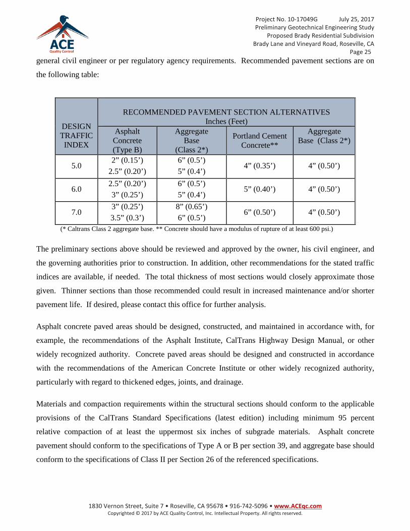
general civil engineer or per regulatory agency requirements. Recommended pavement sections are on
the following table:
DESIGN TRAFFIC INDEX
RECOMMENDED PAVEMENT SECTION ALTERNATIVES
Inches (Feet) Asphalt Concrete (Type B)
Aggregate Base
(Class 2*)
Portland Cement Concrete**
Aggregate Base (Class 2*)
5.0 2” (0.15’)
2.5” (0.20’) 6” (0.5’) 5” (0.4’)
4” (0.35’) 4” (0.50’)
6.0 2.5” (0.20’) 3” (0.25’)
6” (0.5’) 5” (0.4’)
5” (0.40’) 4” (0.50’)
7.0 3” (0.25’) 3.5” (0.3’)
8” (0.65’) 6” (0.5’)
6” (0.50’) 4” (0.50’)
(* Caltrans Class 2 aggregate base. ** Concrete should have a modulus of rupture of at least 600 psi.)
The preliminary sections above should be reviewed and approved by the owner, his civil engineer, and
the governing authorities prior to construction. In addition, other recommendations for the stated traffic
indices are available, if needed. The total thickness of most sections would closely approximate those
given. Thinner sections than those recommended could result in increased maintenance and/or shorter
pavement life. If desired, please contact this office for further analysis.
Asphalt concrete paved areas should be designed, constructed, and maintained in accordance with, for
example, the recommendations of the Asphalt Institute, CalTrans Highway Design Manual, or other
widely recognized authority. Concrete paved areas should be designed and constructed in accordance
with the recommendations of the American Concrete Institute or other widely recognized authority,
particularly with regard to thickened edges, joints, and drainage.
Materials and compaction requirements within the structural sections should conform to the applicable
provisions of the CalTrans Standard Specifications (latest edition) including minimum 95 percent
relative compaction of at least the uppermost six inches of subgrade materials. Asphalt concrete
pavement should conform to the specifications of Type A or B per section 39, and aggregate base should
conform to the specifications of Class II per Section 26 of the referenced specifications.
Project No. 10-17049G July 25, 2017 Preliminary Geotechnical Engineering Study
Proposed Brady Residential Subdivision Brady Lane and Vineyard Road, Roseville, CA
Page 26
1830 Vernon Street, Suite 7 • Roseville, CA 95678 • 916-742-5096 • www.ACEqc.com Copyrighted © 2017 by ACE Quality Control, Inc. Intellectual Property. All rights reserved.
Concrete pavements could be reinforced with nominal rebar, such as minimum #4 bars spaced no greater
than 24 inches, on center, both ways, placed at above mid-slab height, but with proper concrete cover, as
designed by the pavement engineer. Alternatively, concrete pavements can be unreinforced provided
they are constructed with expansion/contraction and/or construction joints spaced no greater than 24
times the pavement thickness, both ways, in nearly square patterns, and are detailed in general
accordance with ACI Guidelines. Doweling of concrete pavements at critical pathways is also
recommended.
We recommend that reinforced concrete pads be provided for truck pad areas – especially at least 30 feet
in front of and beneath trash receptacles. The trash collection trucks should be parked on the rigid
concrete pavement when the trash receptacles are lifted. The concrete pads should be at least 5 inches
thick and properly reinforced. Thickened edges should be used along outside edges of concrete
pavements. Edge thickness should be at least 2 inches thicker than concrete pavement thickness and
taper to the actual concrete pavement thickness 36 inches inward from the edge. Integral curbs may be
used in lieu of thickened edges.
The above pavement section alternatives were calculated on the basis that a comparable soil type to that
tested would constitute the final subgrade of the pavement. ACE should be retained to observe final
subgrade soil(s) exposed to affirm that the soil is comparable to that tested. Where differing earth
materials are encountered they should be tested to affirm that they will also provide the same or better
support for pavement sections similar to those above.
The above sections should be used for preliminary design and planning purposes only. We recommend
representative subgrade sample(s) be obtained and additional "R" Value test(s) be performed on actual
earth materials exposed once pavements have been pioneered. These additional test results may then be
used to evaluate pavement sections for construction. It is possible that significant variations in
pavement sections (vs. those listed above) could result if the resulting test(s) is/are different than that
used for this study.
Adequate drainage systems should be provided to prevent both surface and subsurface saturation of the
subgrade soils. As a design option, a subdrain system beneath and along the edges of the pavements
might be considered. The purpose of the system would be to mitigate saturation and loss of
strength/stability of the subgrade soils. Subdrains should be especially considered beneath valley drains,
Project No. 10-17049G July 25, 2017 Preliminary Geotechnical Engineering Study
Proposed Brady Residential Subdivision Brady Lane and Vineyard Road, Roseville, CA
Page 27
1830 Vernon Street, Suite 7 • Roseville, CA 95678 • 916-742-5096 • www.ACEqc.com Copyrighted © 2017 by ACE Quality Control, Inc. Intellectual Property. All rights reserved.
if utilized for the project. As an alternate to edge drains (especially around landscape planters), barrier
curbing that extends to at least four inches into the soil subgrade below the bottom of the aggregate base
layer could be considered to limit infiltration of water beneath the adjacent pavement. Drainage inlets
should be perforated (weep holes installed) at the level of the aggregate base layer. A layer of geotextile
fabric should be placed on the outside of the drain inlet over the weep holes to reduce the potential for
migration or piping of fines through the holes.
Base course or pavement materials should not be placed when the subgrade surface is wet. Surface
drainage should be provided away from the edge of paved areas to minimize lateral moisture
transmission into the subgrade.
Pavement Construction Considerations On most project sites, the site grading is generally accomplished early in the construction phase.
However, as construction proceeds, the subgrades may become disturbed due to utility excavations,
construction traffic, rainfall, etc. As a result, the pavement subgrade may not be suitable for placement
of aggregate base and pavement. We recommend the area underlying the pavement be rough graded and
proof-rolled prior to placement of aggregate base material. Particular attention should be paid to high
traffic areas and utility trenches that were backfilled. Areas where disturbance has occurred and
materials are unsuitable should be removed and replaced with compacted structural fill.
The aggregate base should be uniformly moisture-conditioned and compacted to a minimum of 95
percent relative compaction (modified proctor) in accordance with this report. Base course or pavement
materials should not be placed when the surface is wet. Surface drainage should be provided away from
the edge of paved areas to minimize lateral moisture transmission into the subgrade.
Minimizing subgrade saturation is an important factor in maintaining subgrade strength. Water allowed
to pond on or adjacent to pavements could saturate the subgrade and cause premature pavement
deterioration. The pavement should be sloped to provide rapid surface drainage, and positive surface
drainage should be maintained away from the edge of the paved areas. Design alternatives which could
reduce the risk of subgrade saturation and improve long-term pavement performance include crowning
the pavement subgrades to drain toward the edges, rather than to the center of the pavement areas; and
installing surface drains next to any areas where surface water could pond. Properly designed and
Project No. 10-17049G July 25, 2017 Preliminary Geotechnical Engineering Study
Proposed Brady Residential Subdivision Brady Lane and Vineyard Road, Roseville, CA
Page 28
1830 Vernon Street, Suite 7 • Roseville, CA 95678 • 916-742-5096 • www.ACEqc.com Copyrighted © 2017 by ACE Quality Control, Inc. Intellectual Property. All rights reserved.
constructed subsurface drainage will reduce the time subgrade soils are saturated and can also improve
subgrade strength and performance. In areas where there will be irrigation adjacent to pavements, we
recommend the owner consider installing perimeter drains for the pavements.
Preventative maintenance should be planned and provided for through an on-going pavement
management program in order to enhance future pavement performance. Preventative maintenance
activities are intended to slow the rate of pavement deterioration, and to preserve the pavement
investment.
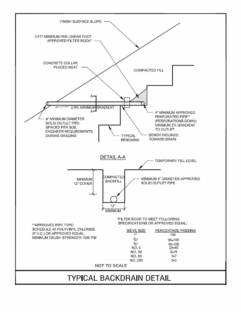
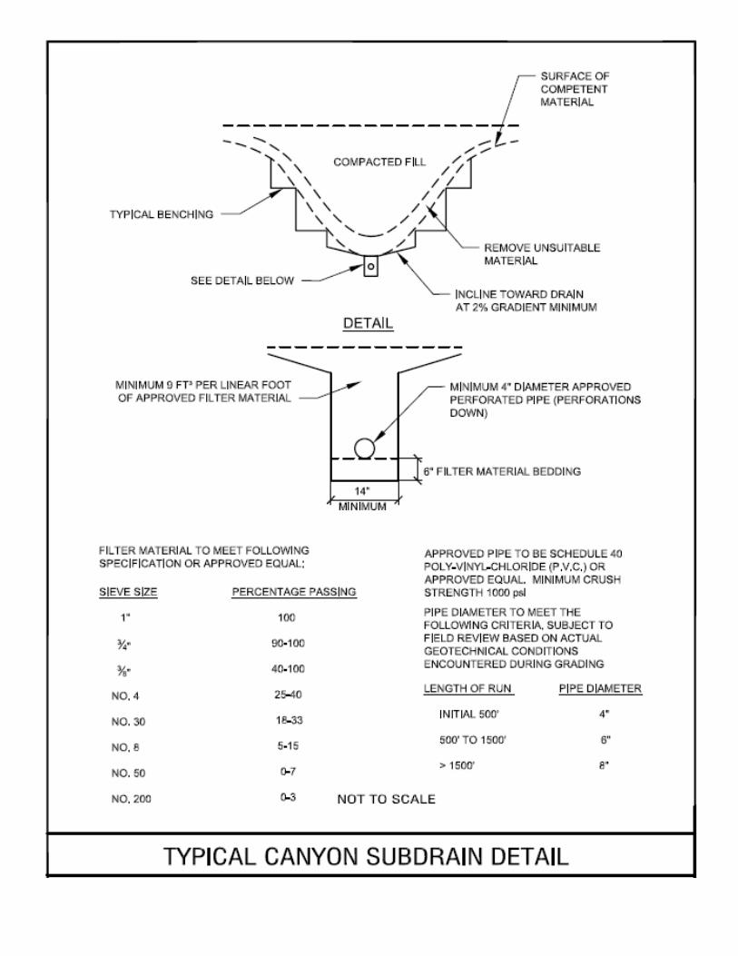
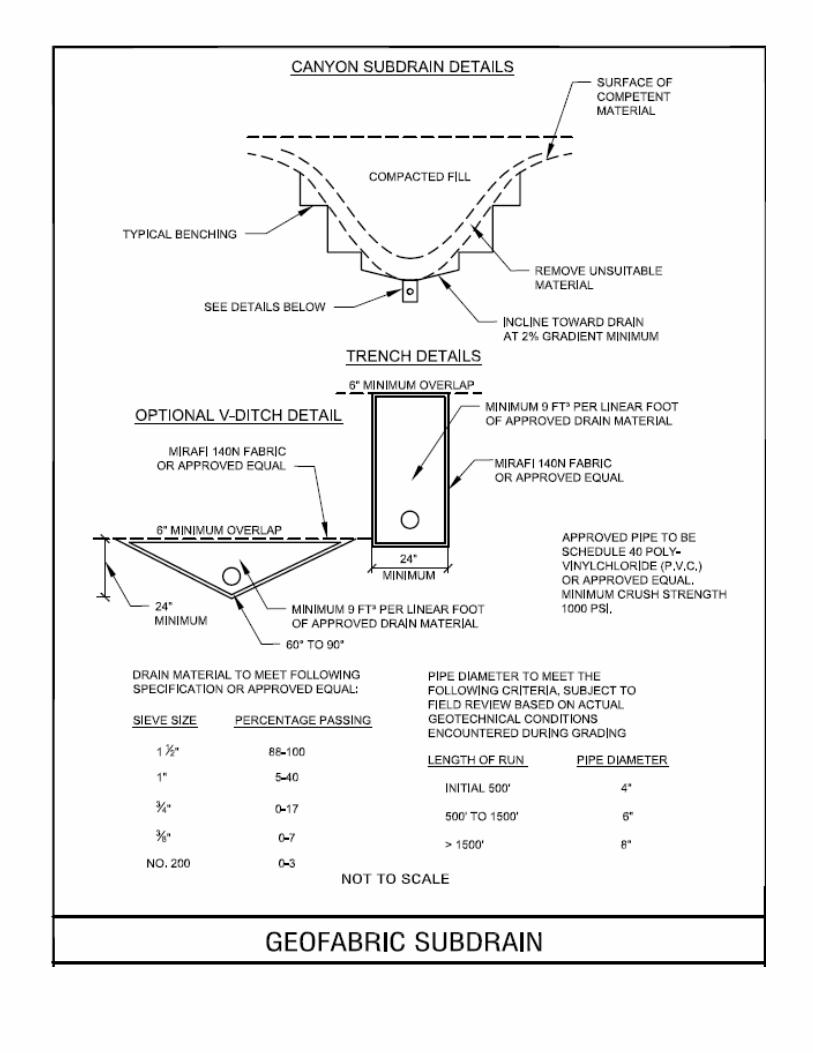
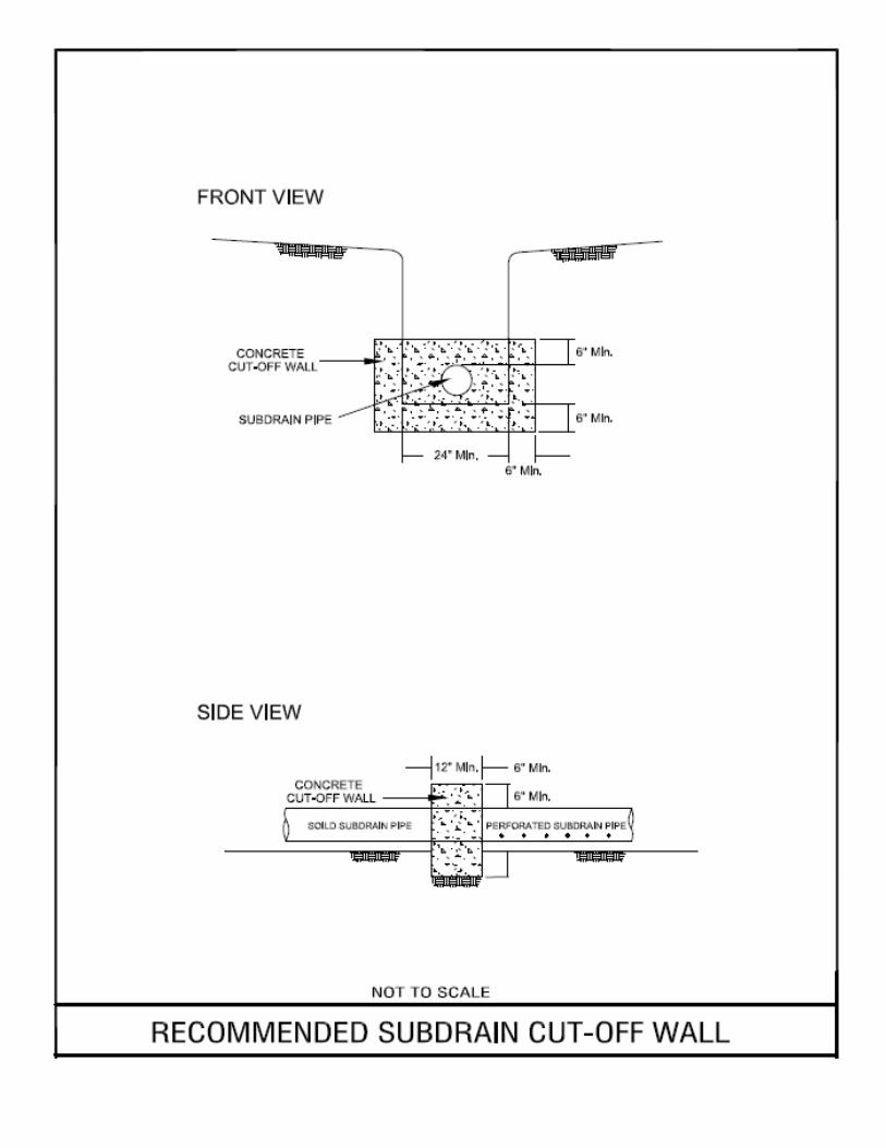
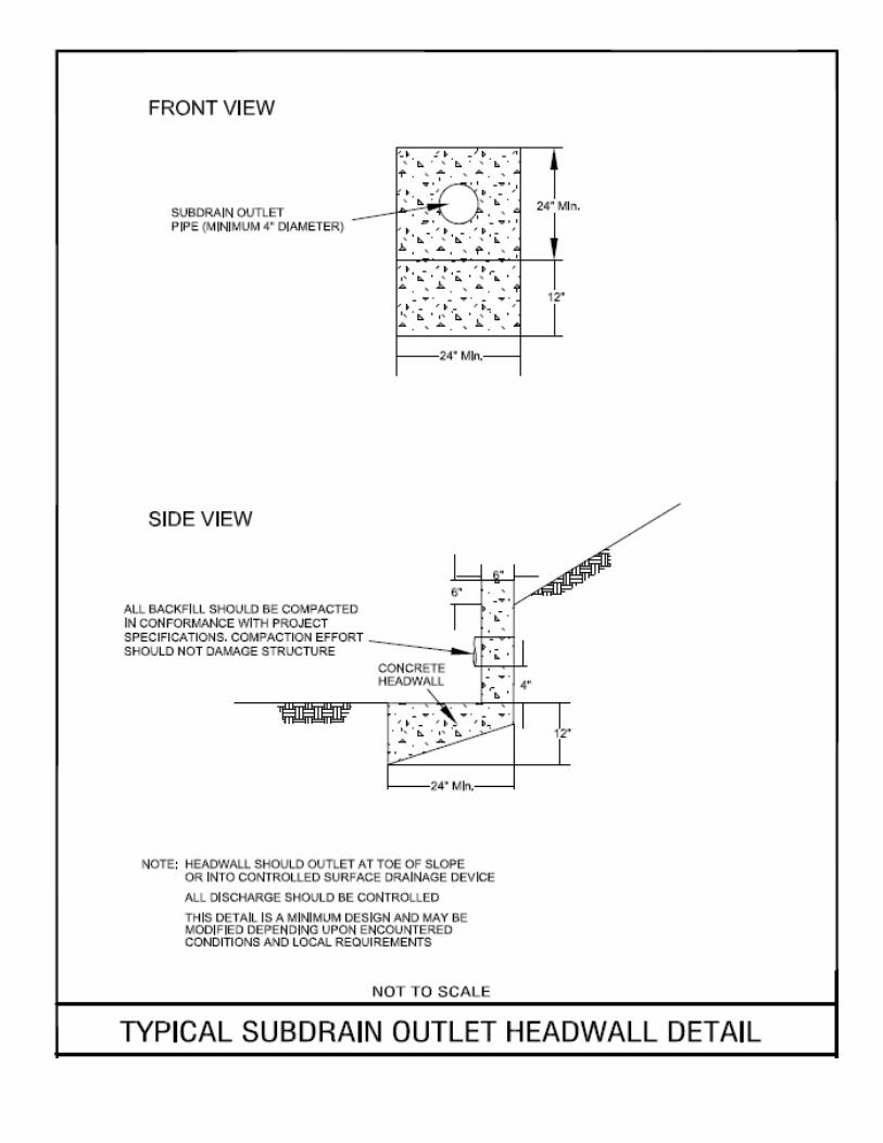
Subdrainage Subdrains might be needed to control subsurface water that might become perched in top and/or fill
soils. Each case should be evaluated by the Geotechnical Engineer so that he could make appropriate
mitigation recommendations.
LIMITATIONS The analysis and recommendations submitted in this report are based in part upon the data from the exploratory borings at the indicated locations and in part on information provided by the client. The nature and extent of subsurface variations between the test borings across the site (or due to the modifying effects of weather and/or man) may not become evident until further exploration or during construction. If variations then appear evident, then the conclusions, opinions, and recommendations in this report shall be considered invalid, unless the variations are reviewed and the conclusions, opinions, and recommendations are modified or approved in writing. This report was prepared in order to assist the client in the evaluation of the site and to assist the architect and/or engineer in the design of the improvements. This firm should be provided the opportunity for a general review of final plans and specifications to determine that the recommendations of this report have been properly interpreted and implemented in the plans and specifications. In the event that there are any significant changes in the project as described herein, then the conclusions and recommendations contained in this report shall not be considered valid unless the changes are reviewed and conclusions and recommendations modified or verified in writing. This report is issued for the client’s use only. In addition, it is his responsibility to ensure that the information and recommendations contained herein are called to the attention of the designer for the project; and, that necessary steps are taken to implement the recommendations during construction.
Project No. 10-17049G July 25, 2017 Preliminary Geotechnical Engineering Study
Proposed Brady Residential Subdivision Brady Lane and Vineyard Road, Roseville, CA
Page 30
1830 Vernon Street, Suite 7 • Roseville, CA 95678 • 916-742-5096 • www.ACEqc.com Copyrighted © 2017 by ACE Quality Control, Inc. Intellectual Property. All rights reserved.
REFERENCES
1. American Society for Civil Engineers, 2013, “Minimum Design Loads for Buildings and Other Structures,” ASCE/SEI 7-10.
2. ASTM, “Test Method for Laboratory Compaction Characteristics of Soil Using Modified Effort,” Volume 04.08 3. California Building Code, 2013, “California Code of Regulations, Title 24, Part 2, Volume 2 of 2,” California
Building Standards Commission, published by ICBO. 4. California Geological Survey (CGS), Geologic Map 1A “Preliminary Geologic Map of the Sacramento
Quadrangle”, third printing 2010; scale 1: 250,000, compiled by Carlos I. Gutierrez. 5. CGS website (http://gmw.consrv.ca.gov/shmp/html/pdf_maps_no.html) for Regulatory Maps, Reports and GIS data
that includes Earthquake Fault Zones, Landslide and Liquefaction Zones. 6. Hart, Earl W., Revised 1994, "Fault-Rupture Hazard Zones in California, Alquist Priolo, Special Studies Zones Act
of 1972,” California Division of Mines and Geology, Special Publication 42. 7. Jennings, Charles W. and Bryant, William A., 2010, “Fault Activity Map of California” (scale 1: 750,000) published
by CGS, Geologic Data Map No. 6. 8. United States Geological Survey (USGS) Earthquake Design Maps (http://ehp1-
earthquake.cr.usgs.gov/designmaps/us/ - which utilizes USGS hazard data available in 2008), reference 2012 International Building Code/2013 California Building Code.
9. Google earth aerial photography of the subject site. 10. Seed, H.B. and Whitman, R.V. (1970). “Design of Earth Retaining Structures for Dynamic Loads,” ASCE Specialty
Conference, Lateral Stresses in the Ground and Design of Earth Retaining Structures, Cornell Univ., Ithaca, New York, 103–147.
11. Wood, J.H. (1973). “Earthquake Induced Soil Pressures on Structures,” PhD Thesis, California Institute of Technology, Pasadena, CA.
APPENDIX A
GRAPHIC PRESENTATIONS
VICINITY MAP
EXPLORATIONS MAP
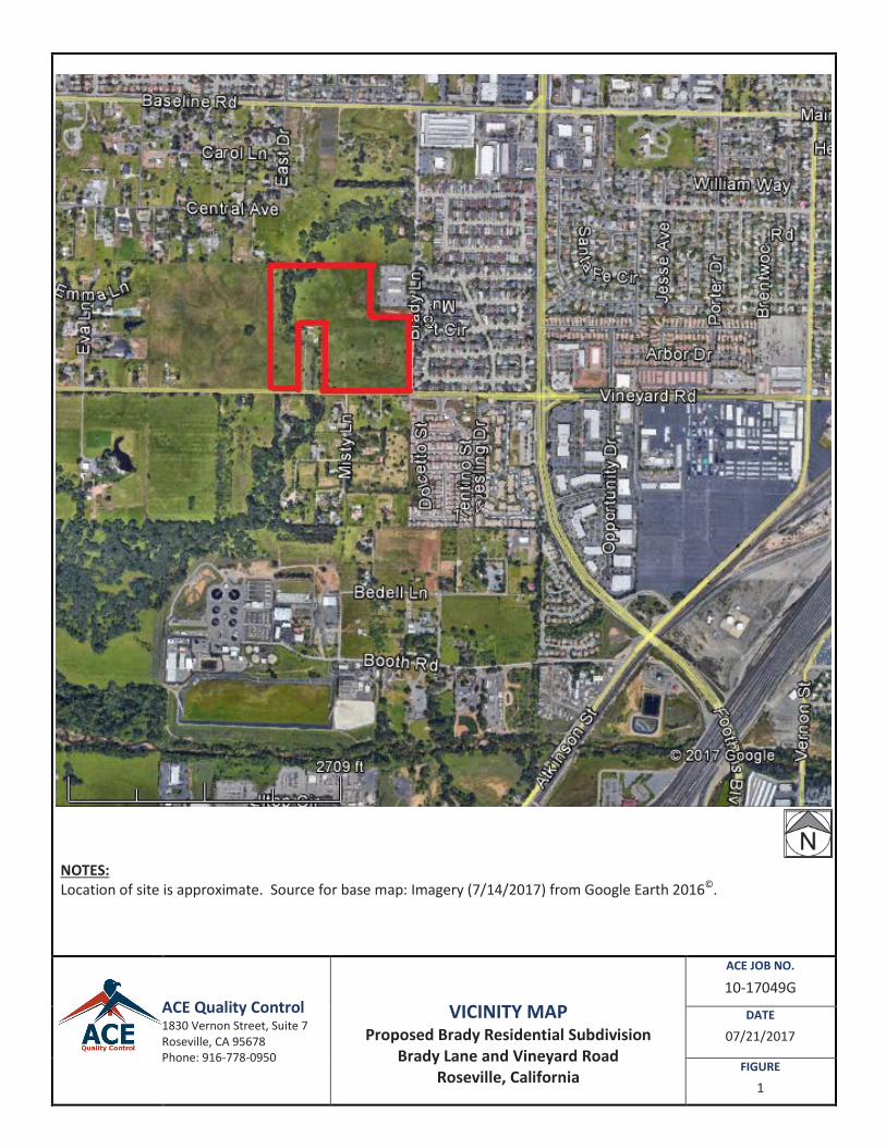
NOTES: Location of site is approximate. Source for base map: Imagery (7/14/2017) from Google Earth 2016©.
ACE Quality Control 1830 Vernon Street, Suite 7 Roseville, CA 95678 Phone: 916-778-0950
VICINITY MAP
Proposed Brady Residential Subdivision Brady Lane and Vineyard Road
Roseville, California
ACE JOB NO.
10-17049G
DATE
07/21/2017
FIGURE
1
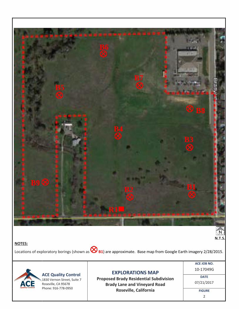
N.T.S.
NOTES:
Locations of exploratory borings (shown as B1) are approximate. Base map from Google Earth imagery 2/28/2015.
ACE Quality Control 1830 Vernon Street, Suite 7 Roseville, CA 95678 Phone: 916-778-0950
EXPLORATIONS MAP Proposed Brady Residential Subdivision
Brady Lane and Vineyard Road Roseville, California
ACE JOB NO.
10-17049G
DATE
07/21/2017
FIGURE
2
B3
B1 B2
R1
B5
B6
B8
B7
B9
B4

APPENDIX B
FIELD EXPLORATION METHODS
LOGS OF SUBSURFACE EXPLORATIONS
LEGEND
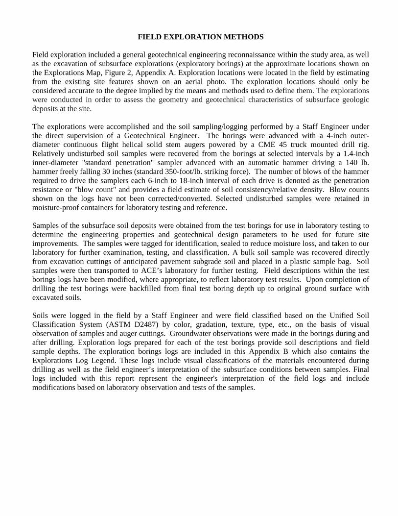
FIELD EXPLORATION METHODS Field exploration included a general geotechnical engineering reconnaissance within the study area, as well as the excavation of subsurface explorations (exploratory borings) at the approximate locations shown on the Explorations Map, Figure 2, Appendix A. Exploration locations were located in the field by estimating from the existing site features shown on an aerial photo. The exploration locations should only be considered accurate to the degree implied by the means and methods used to define them. The explorations were conducted in order to assess the geometry and geotechnical characteristics of subsurface geologic deposits at the site. The explorations were accomplished and the soil sampling/logging performed by a Staff Engineer under the direct supervision of a Geotechnical Engineer. The borings were advanced with a 4-inch outer-diameter continuous flight helical solid stem augers powered by a CME 45 truck mounted drill rig. Relatively undisturbed soil samples were recovered from the borings at selected intervals by a 1.4-inch inner-diameter "standard penetration" sampler advanced with an automatic hammer driving a 140 lb. hammer freely falling 30 inches (standard 350-foot/lb. striking force). The number of blows of the hammer required to drive the samplers each 6-inch to 18-inch interval of each drive is denoted as the penetration resistance or "blow count" and provides a field estimate of soil consistency/relative density. Blow counts shown on the logs have not been corrected/converted. Selected undisturbed samples were retained in moisture-proof containers for laboratory testing and reference. Samples of the subsurface soil deposits were obtained from the test borings for use in laboratory testing to determine the engineering properties and geotechnical design parameters to be used for future site improvements. The samples were tagged for identification, sealed to reduce moisture loss, and taken to our laboratory for further examination, testing, and classification. A bulk soil sample was recovered directly from excavation cuttings of anticipated pavement subgrade soil and placed in a plastic sample bag. Soil samples were then transported to ACE’s laboratory for further testing. Field descriptions within the test borings logs have been modified, where appropriate, to reflect laboratory test results. Upon completion of drilling the test borings were backfilled from final test boring depth up to original ground surface with excavated soils. Soils were logged in the field by a Staff Engineer and were field classified based on the Unified Soil Classification System (ASTM D2487) by color, gradation, texture, type, etc., on the basis of visual observation of samples and auger cuttings. Groundwater observations were made in the borings during and after drilling. Exploration logs prepared for each of the test borings provide soil descriptions and field sample depths. The exploration borings logs are included in this Appendix B which also contains the Explorations Log Legend. These logs include visual classifications of the materials encountered during drilling as well as the field engineer’s interpretation of the subsurface conditions between samples. Final logs included with this report represent the engineer's interpretation of the field logs and include modifications based on laboratory observation and tests of the samples.
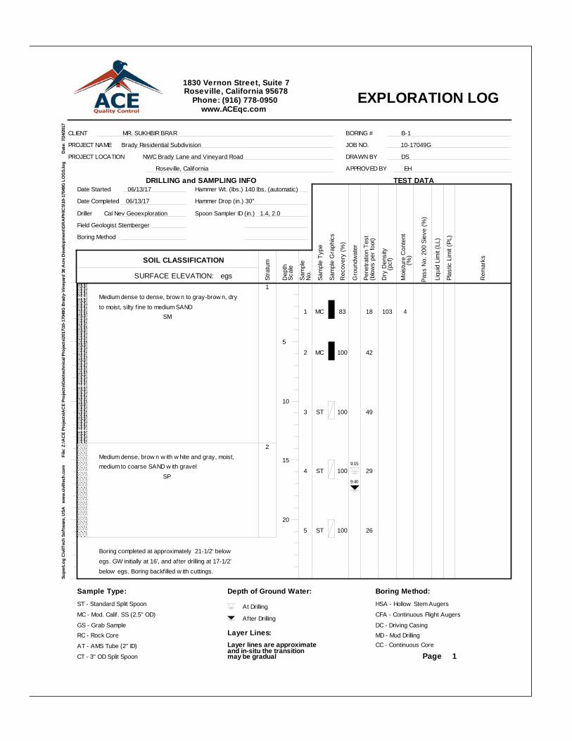
1Medium dense to dense, brow n to gray-brow n, dryto moist, silty f ine to medium SAND SM
2Medium dense, brow n w ith w hite and gray, moist,medium to coarse SAND w ith gravel SP
Boring completed at approximately 21-1/2' belowegs. GW initially at 16', and after drilling at 17-1/2'below egs. Boring backfilled w ith cuttings.
1 MC 83 18 103 4
2 MC 100 42
3 ST 100 49
4 ST 100 29
5 ST 100 26
9:40
9:15
EXPLORATION LOG
Supe
rLog
Civ
ilTec
h So
ftw
are,
USA
w
ww
.civ
iltec
h.co
m
F
ile: Z
:\AC
E Pr
ojec
ts\A
CE
Proj
ects
\Geo
tech
nica
l Pro
ject
s\20
17\1
0-17
049G
Bra
dy-V
iney
ard
36 A
cre
Dev
elop
men
t\GR
APH
ICS\
10-1
7049
G L
OG
S.lo
g
D
ate:
7/2
4/20
17
CLIENT MR. SUKHBIR BRAR
PROJECT NAME Brady Residential Subdivision
PROJECT LOCATION NWC Brady Lane and Vineyard Road
Roseville, California
JOB NO. 10-17049G
DRAWN BY DS
APPROVED BY EH
BORING # B-1
Date Started 06/13/17
Date Completed 06/13/17
Driller Cal Nev Geoexploration
Field Geologist Stemberger
Boring Method
Hammer Wt. (lbs.) 140 lbs. (automatic)
Hammer Drop (in.) 30"
Spoon Sampler ID (in.) 1.4, 2.0
SURFACE ELEVATION: egs
SOIL CLASSIFICATIONSt
ratu
m
Dep
th
Sam
ple
Gro
undw
ater
(blo
ws
per f
oot)
Sam
ple
Type
Pene
tratio
n Te
st
Moi
stur
e C
onte
nt
Pass
No.
200
Sie
ve (%
)
Rem
arks
Page
Dry
Den
sity
(pcf
)
1830 Vernon Street, Suite 7Roseville, California 95678
Phone: (916) 778-0950www.ACEqc.com
DRILLING and SAMPLING INFO
Scal
e
No.
Rec
over
y (%
)
(%
)
TEST DATA
Sam
ple
Gra
phic
s
Liqu
id L
imit
(LL)
Plas
tic L
imit
(PL)
Sample Type:ST - Standard Split Spoon
MC - Mod. Calif . SS (2.5" OD)
GS - Grab SampleRC - Rock Core
AT - AMS Tube (2" ID)
CT - 3" OD Split Spoon
Depth of Ground Water:
At Drilling
After Drilling
Layer Lines:Layer lines are approximateand in-situ the transition may be gradual
Boring Method:HSA - Hollow Stem Augers
CFA - Continuous Flight Augers
DC - Driving CasingMD - Mud DrillingCC - Continuous Core
5
10
15
20
1
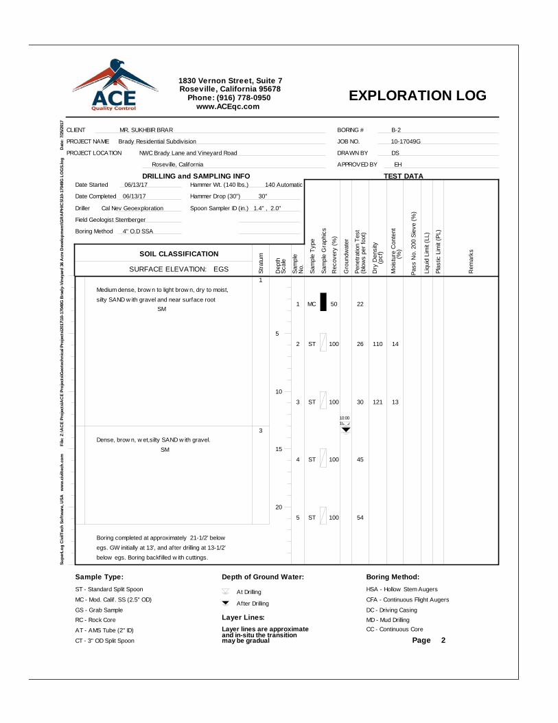
1Medium dense, brow n to light brow n, dry to moist,silty SAND w ith gravel and near surface root SM
3Dense, brow n, w et,silty SAND w ith gravel. SM
Boring completed at approximately 21-1/2' belowegs. GW initially at 13', and after drilling at 13-1/2'below egs. Boring backfilled w ith cuttings.
1 MC 50 22
2 ST 100 26 110 14
3 ST 100 30 121 13
4 ST 100 45
5 ST 100 54
10:2010:00
EXPLORATION LOG
Supe
rLog
Civ
ilTec
h So
ftw
are,
USA
w
ww
.civ
iltec
h.co
m
F
ile: Z
:\AC
E Pr
ojec
ts\A
CE
Proj
ects
\Geo
tech
nica
l Pro
ject
s\20
17\1
0-17
049G
Bra
dy-V
iney
ard
36 A
cre
Dev
elop
men
t\GR
APH
ICS\
10-1
7049
G L
OG
S.lo
g
D
ate:
7/2
5/20
17
CLIENT MR. SUKHBIR BRAR
PROJECT NAME Brady Residential Subdivision
PROJECT LOCATION NWC Brady Lane and Vineyard Road
Roseville, California
JOB NO. 10-17049G
DRAWN BY DS
APPROVED BY EH
BORING # B-2
Date Started 06/13/17
Date Completed 06/13/17
Driller Cal Nev Geoexploration
Field Geologist Stemberger
Boring Method 4" O.D SSA
Hammer Wt. (140 lbs.) 140 Automatic
Hammer Drop (30") 30"
Spoon Sampler ID (in.) 1.4" , 2.0"
SURFACE ELEVATION: EGS
SOIL CLASSIFICATIONSt
ratu
m
Dep
th
Sam
ple
Gro
undw
ater
(blo
ws
per f
oot)
Sam
ple
Type
Pene
tratio
n Te
st
Moi
stur
e C
onte
nt
Pass
No.
200
Sie
ve (%
)
Rem
arks
Page
Dry
Den
sity
(pcf
)
1830 Vernon Street, Suite 7Roseville, California 95678
Phone: (916) 778-0950www.ACEqc.com
DRILLING and SAMPLING INFO
Scal
e
No.
Rec
over
y (%
)
(%
)
TEST DATA
Sam
ple
Gra
phic
s
Liqu
id L
imit
(LL)
Plas
tic L
imit
(PL)
Sample Type:ST - Standard Split Spoon
MC - Mod. Calif . SS (2.5" OD)
GS - Grab SampleRC - Rock Core
AT - AMS Tube (2" ID)
CT - 3" OD Split Spoon
Depth of Ground Water:
At Drilling
After Drilling
Layer Lines:Layer lines are approximateand in-situ the transition may be gradual
Boring Method:HSA - Hollow Stem Augers
CFA - Continuous Flight Augers
DC - Driving CasingMD - Mud DrillingCC - Continuous Core
5
10
15
20
2
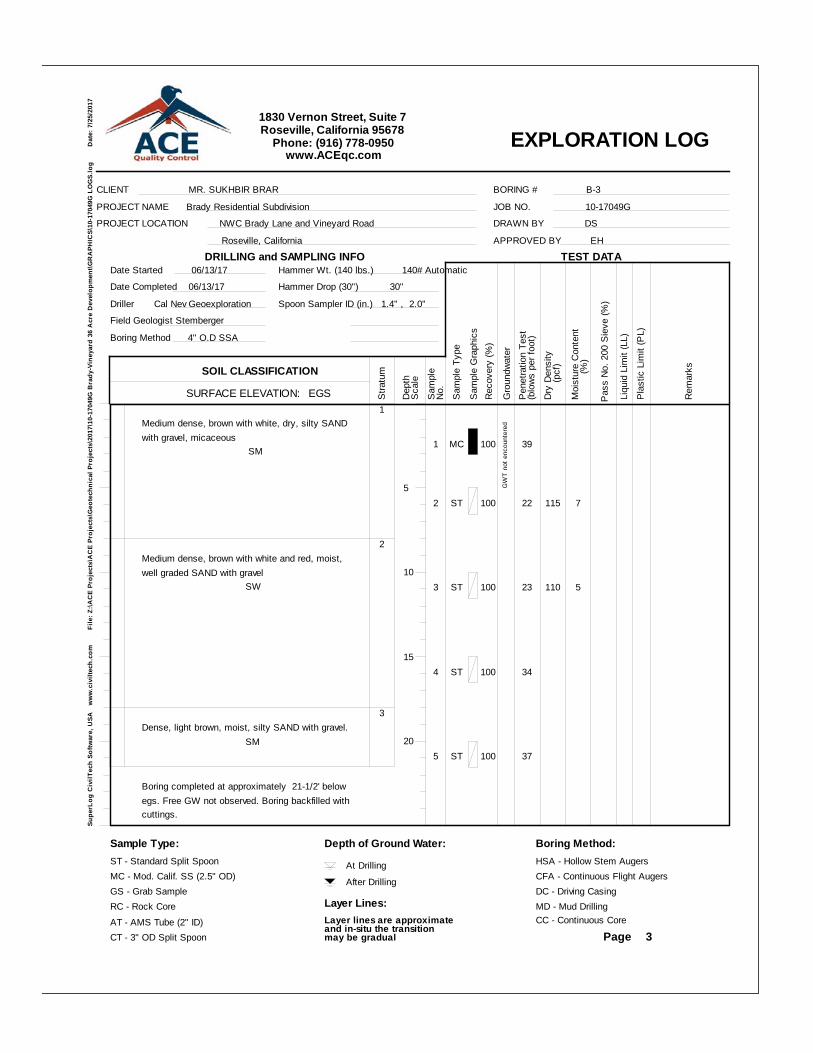
1Medium dense, brown with white, dry, silty SANDwith gravel, micaceous SM
2Medium dense, brown with white and red, moist,well graded SAND with gravel SW
3Dense, light brown, moist, silty SAND with gravel. SM
Boring completed at approximately 21-1/2' belowegs. Free GW not observed. Boring backfilled withcuttings.
1 MC 100 39
2 ST 100 22 115 7
3 ST 100 23 110 5
4 ST 100 34
5 ST 100 37
GW
T no
t enc
ount
ered
EXPLORATION LOG
Supe
rLog
Civ
ilTec
h So
ftwar
e, U
SA
ww
w.c
ivilt
ech.
com
File
: Z:\A
CE
Proj
ects
\AC
E Pr
ojec
ts\G
eote
chni
cal P
roje
cts\
2017
\10-
1704
9G B
rady
-Vin
eyar
d 36
Acr
e D
evel
opm
ent\G
RA
PHIC
S\10
-170
49G
LO
GS.
log
Dat
e: 7
/25/
2017
CLIENT MR. SUKHBIR BRAR
PROJECT NAME Brady Residential Subdivision
PROJECT LOCATION NWC Brady Lane and Vineyard Road
Roseville, California
JOB NO. 10-17049G
DRAWN BY DS
APPROVED BY EH
BORING # B-3
Date Started 06/13/17
Date Completed 06/13/17
Driller Cal Nev Geoexploration
Field Geologist Stemberger
Boring Method 4" O.D SSA
Hammer Wt. (140 lbs.) 140# Automatic
Hammer Drop (30") 30"
Spoon Sampler ID (in.) 1.4" , 2.0"
SURFACE ELEVATION: EGS
SOIL CLASSIFICATIONS
tratu
m
Dep
th
Sam
ple
Gro
undw
ater
(blo
ws
per f
oot)
Sam
ple
Type
Pen
etra
tion
Test
Moi
stur
e C
onte
nt
Pas
s N
o. 2
00 S
ieve
(%)
Rem
arks
Page
Dry
Den
sity
(pcf
)
1830 Vernon Street, Suite 7Roseville, California 95678
Phone: (916) 778-0950www.ACEqc.com
DRILLING and SAMPLING INFO
Sca
le
No.
Rec
over
y (%
)
(%
)
TEST DATA
Sam
ple
Gra
phic
s
Liqu
id L
imit
(LL)
Pla
stic
Lim
it (P
L)
Sample Type:ST - Standard Split SpoonMC - Mod. Calif. SS (2.5" OD)GS - Grab SampleRC - Rock CoreAT - AMS Tube (2" ID)CT - 3" OD Split Spoon
Depth of Ground Water:
At Drilling
After Drilling
Layer Lines:Layer lines are approximateand in-situ the transition may be gradual
Boring Method:HSA - Hollow Stem AugersCFA - Continuous Flight AugersDC - Driving CasingMD - Mud DrillingCC - Continuous Core
5
10
15
20
3
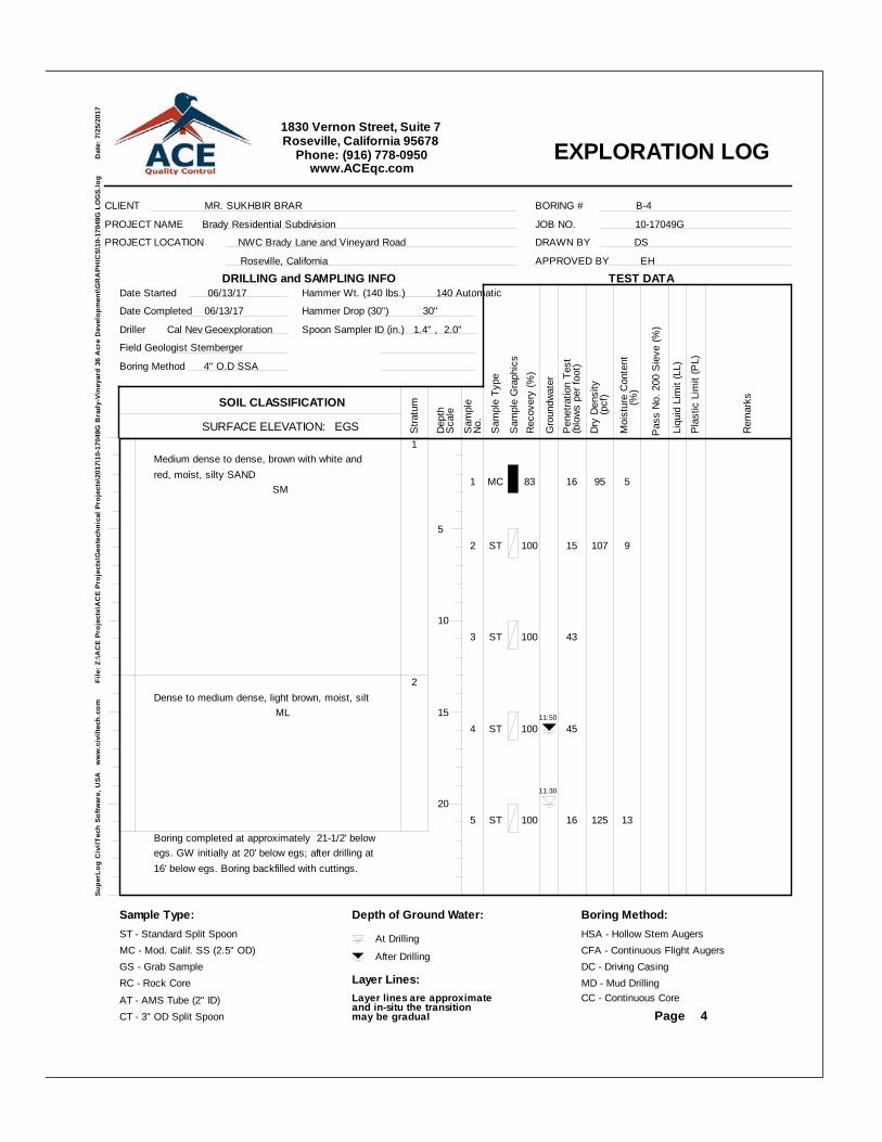
1Medium dense to dense, brown with white andred, moist, silty SAND SM
2Dense to medium dense, light brown, moist, silt ML
Boring completed at approximately 21-1/2' belowegs. GW initially at 20' below egs; after drilling at16' below egs. Boring backfilled with cuttings.
1 MC 83 16 95 5
2 ST 100 15 107 9
3 ST 100 43
4 ST 100 45
5 ST 100 16 125 13
11:50
11:30
EXPLORATION LOG
Supe
rLog
Civ
ilTec
h So
ftwar
e, U
SA
ww
w.c
ivilt
ech.
com
File
: Z:\A
CE
Proj
ects
\AC
E Pr
ojec
ts\G
eote
chni
cal P
roje
cts\
2017
\10-
1704
9G B
rady
-Vin
eyar
d 36
Acr
e D
evel
opm
ent\G
RA
PHIC
S\10
-170
49G
LO
GS.
log
Dat
e: 7
/25/
2017
CLIENT MR. SUKHBIR BRAR
PROJECT NAME Brady Residential Subdivision
PROJECT LOCATION NWC Brady Lane and Vineyard Road
Roseville, California
JOB NO. 10-17049G
DRAWN BY DS
APPROVED BY EH
BORING # B-4
Date Started 06/13/17
Date Completed 06/13/17
Driller Cal Nev Geoexploration
Field Geologist Stemberger
Boring Method 4" O.D SSA
Hammer Wt. (140 lbs.) 140 Automatic
Hammer Drop (30") 30"
Spoon Sampler ID (in.) 1.4" , 2.0"
SURFACE ELEVATION: EGS
SOIL CLASSIFICATIONS
tratu
m
Dep
th
Sam
ple
Gro
undw
ater
(blo
ws
per f
oot)
Sam
ple
Type
Pen
etra
tion
Test
Moi
stur
e C
onte
nt
Pas
s N
o. 2
00 S
ieve
(%)
Rem
arks
Page
Dry
Den
sity
(pcf
)
1830 Vernon Street, Suite 7Roseville, California 95678
Phone: (916) 778-0950www.ACEqc.com
DRILLING and SAMPLING INFO
Sca
le
No.
Rec
over
y (%
)
(%
)
TEST DATA
Sam
ple
Gra
phic
s
Liqu
id L
imit
(LL)
Pla
stic
Lim
it (P
L)
Sample Type:ST - Standard Split SpoonMC - Mod. Calif. SS (2.5" OD)GS - Grab SampleRC - Rock CoreAT - AMS Tube (2" ID)CT - 3" OD Split Spoon
Depth of Ground Water:
At Drilling
After Drilling
Layer Lines:Layer lines are approximateand in-situ the transition may be gradual
Boring Method:HSA - Hollow Stem AugersCFA - Continuous Flight AugersDC - Driving CasingMD - Mud DrillingCC - Continuous Core
5
10
15
20
4

1Dense, light tan, moist, silty SAND with gravel SM
2Dense, brown, moist, SILT ML
3Medium dense to dense, brown, moist, silty fineSAND SM
Boring completed at approximately 21-1/2' belowegs. GW initially and after drilling at 16-1/2'.Boring backfilled with cuttings.
1 MC 100 78
2 ST 100 41 64
3 ST 100 16 112 21
4 ST 100 32
5 ST 100 31
12:45
EXPLORATION LOG
Supe
rLog
Civ
ilTec
h So
ftwar
e, U
SA
ww
w.c
ivilt
ech.
com
File
: Z:\A
CE
Proj
ects
\AC
E Pr
ojec
ts\G
eote
chni
cal P
roje
cts\
2017
\10-
1704
9G B
rady
-Vin
eyar
d 36
Acr
e D
evel
opm
ent\G
RA
PHIC
S\10
-170
49G
LO
GS.
log
Dat
e: 7
/25/
2017
CLIENT MR. SUKHBIR BRAR
PROJECT NAME Brady Residential Subdivision
PROJECT LOCATION NWC Brady Lane and Vineyard Road
Roseville, California
JOB NO. 10-17049G
DRAWN BY DS
APPROVED BY EH
BORING # B-5
Date Started 06/13/17
Date Completed 06/13/17
Driller Cal Nev Geoexploration
Field Geologist Stemberger
Boring Method 4" O.D SSA
Hammer Wt. (140 lbs.) 140 Automatic
Hammer Drop (30") 30"
Spoon Sampler ID (in.) 1.4" , 2.0"
SURFACE ELEVATION: EGS
SOIL CLASSIFICATIONS
tratu
m
Dep
th
Sam
ple
Gro
undw
ater
(blo
ws
per f
oot)
Sam
ple
Type
Pen
etra
tion
Test
Moi
stur
e C
onte
nt
Pas
s N
o. 2
00 S
ieve
(%)
Rem
arks
Page
Dry
Den
sity
(pcf
)
1830 Vernon Street, Suite 7Roseville, California 95678
Phone: (916) 778-0950www.ACEqc.com
DRILLING and SAMPLING INFO
Sca
le
No.
Rec
over
y (%
)
(%
)
TEST DATA
Sam
ple
Gra
phic
s
Liqu
id L
imit
(LL)
Pla
stic
Lim
it (P
L)
Sample Type:ST - Standard Split SpoonMC - Mod. Calif. SS (2.5" OD)GS - Grab SampleRC - Rock CoreAT - AMS Tube (2" ID)CT - 3" OD Split Spoon
Depth of Ground Water:
At Drilling
After Drilling
Layer Lines:Layer lines are approximateand in-situ the transition may be gradual
Boring Method:HSA - Hollow Stem AugersCFA - Continuous Flight AugersDC - Driving CasingMD - Mud DrillingCC - Continuous Core
5
10
15
20
5
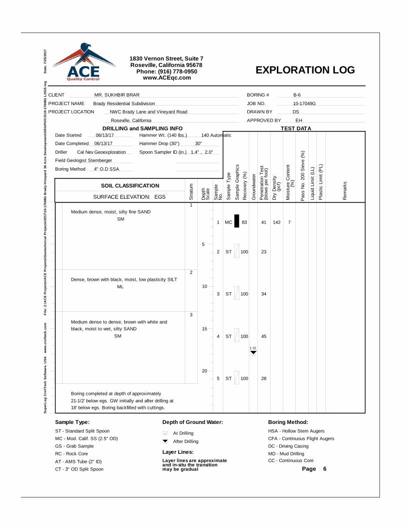
1Medium dense, moist, silty fine SAND SM
2Dense, brown with black, moist, low plasticity SILT ML
3Medium dense to dense, brown with white andblack, moist to wet, silty SAND SM
Boring completed at depth of approximately21-1/2' below egs. GW initially and after drilling at18' below egs. Boring backfilled with cuttings.
1 MC 83 41 142 7
2 ST 100 23
3 ST 100 34
4 ST 100 45
5 ST 100 28
1:15
EXPLORATION LOG
Supe
rLog
Civ
ilTec
h So
ftwar
e, U
SA
ww
w.c
ivilt
ech.
com
File
: Z:\A
CE
Proj
ects
\AC
E Pr
ojec
ts\G
eote
chni
cal P
roje
cts\
2017
\10-
1704
9G B
rady
-Vin
eyar
d 36
Acr
e D
evel
opm
ent\G
RA
PHIC
S\10
-170
49G
LO
GS.
log
Dat
e: 7
/25/
2017
CLIENT MR. SUKHBIR BRAR
PROJECT NAME Brady Residential Subdivision
PROJECT LOCATION NWC Brady Lane and Vineyard Road
Roseville, California
JOB NO. 10-17049G
DRAWN BY DS
APPROVED BY EH
BORING # B-6
Date Started 06/13/17
Date Completed 06/13/17
Driller Cal Nev Geoexploration
Field Geologist Stemberger
Boring Method 4" O.D SSA
Hammer Wt. (140 lbs.) 140 Automatic
Hammer Drop (30") 30"
Spoon Sampler ID (in.) 1.4" , 2.0"
SURFACE ELEVATION: EGS
SOIL CLASSIFICATIONS
tratu
m
Dep
th
Sam
ple
Gro
undw
ater
(blo
ws
per f
oot)
Sam
ple
Type
Pen
etra
tion
Test
Moi
stur
e C
onte
nt
Pas
s N
o. 2
00 S
ieve
(%)
Rem
arks
Page
Dry
Den
sity
(pcf
)
1830 Vernon Street, Suite 7Roseville, California 95678
Phone: (916) 778-0950www.ACEqc.com
DRILLING and SAMPLING INFO
Sca
le
No.
Rec
over
y (%
)
(%
)
TEST DATA
Sam
ple
Gra
phic
s
Liqu
id L
imit
(LL)
Pla
stic
Lim
it (P
L)
Sample Type:ST - Standard Split SpoonMC - Mod. Calif. SS (2.5" OD)GS - Grab SampleRC - Rock CoreAT - AMS Tube (2" ID)CT - 3" OD Split Spoon
Depth of Ground Water:
At Drilling
After Drilling
Layer Lines:Layer lines are approximateand in-situ the transition may be gradual
Boring Method:HSA - Hollow Stem AugersCFA - Continuous Flight AugersDC - Driving CasingMD - Mud DrillingCC - Continuous Core
5
10
15
20
6

1Medium dense to dense, brown with gray andwhite, moist, silty SAND SM
Boring completed at approximately 21-1/2' belowegs. Free groundwater not encountered. Boringbackfilled with cuttings.
1 MC 100 24 105 4
2 ST 100 31 126 14
3 ST 100 41
4 ST 100 29 116 18
5 ST 100 27 132 16
GW
T no
t enc
ount
ered
EXPLORATION LOG
Supe
rLog
Civ
ilTec
h So
ftwar
e, U
SA
ww
w.c
ivilt
ech.
com
File
: Z:\A
CE
Proj
ects
\AC
E Pr
ojec
ts\G
eote
chni
cal P
roje
cts\
2017
\10-
1704
9G B
rady
-Vin
eyar
d 36
Acr
e D
evel
opm
ent\G
RA
PHIC
S\10
-170
49G
LO
GS.
log
Dat
e: 7
/25/
2017
CLIENT MR. SUKHBIR BRAR
PROJECT NAME Brady Residential Subdivision
PROJECT LOCATION NWC Brady Lane and Vineyard Road
Roseville, California
JOB NO. 10-17049G
DRAWN BY DS
APPROVED BY EH
BORING # B-7
Date Started 06/13/17
Date Completed 06/13/17
Driller Cal Nev Geoexploration
Field Geologist Stemberger
Boring Method 4" O.D SSA
Hammer Wt. (140 lbs.) 140 Automatic
Hammer Drop (30") 30"
Spoon Sampler ID (in.) 1.4" , 2.0"
SURFACE ELEVATION: EGS
SOIL CLASSIFICATIONS
tratu
m
Dep
th
Sam
ple
Gro
undw
ater
(blo
ws
per f
oot)
Sam
ple
Type
Pen
etra
tion
Test
Moi
stur
e C
onte
nt
Pas
s N
o. 2
00 S
ieve
(%)
Rem
arks
Page
Dry
Den
sity
(pcf
)
1830 Vernon Street, Suite 7Roseville, California 95678
Phone: (916) 778-0950www.ACEqc.com
DRILLING and SAMPLING INFO
Sca
le
No.
Rec
over
y (%
)
(%
)
TEST DATA
Sam
ple
Gra
phic
s
Liqu
id L
imit
(LL)
Pla
stic
Lim
it (P
L)
Sample Type:ST - Standard Split SpoonMC - Mod. Calif. SS (2.5" OD)GS - Grab SampleRC - Rock CoreAT - AMS Tube (2" ID)CT - 3" OD Split Spoon
Depth of Ground Water:
At Drilling
After Drilling
Layer Lines:Layer lines are approximateand in-situ the transition may be gradual
Boring Method:HSA - Hollow Stem AugersCFA - Continuous Flight AugersDC - Driving CasingMD - Mud DrillingCC - Continuous Core
5
10
15
20
7
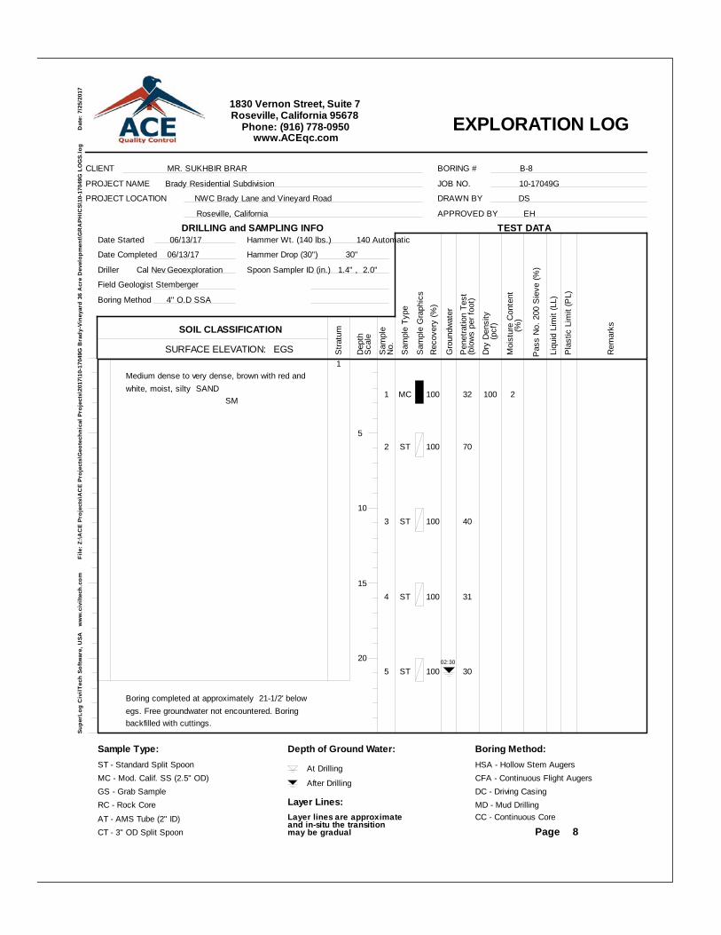
1Medium dense to very dense, brown with red andwhite, moist, silty SAND SM
Boring completed at approximately 21-1/2' belowegs. Free groundwater not encountered. Boringbackfilled with cuttings.
1 MC 100 32 100 2
2 ST 100 70
3 ST 100 40
4 ST 100 31
5 ST 100 3002:30
EXPLORATION LOG
Supe
rLog
Civ
ilTec
h So
ftwar
e, U
SA
ww
w.c
ivilt
ech.
com
File
: Z:\A
CE
Proj
ects
\AC
E Pr
ojec
ts\G
eote
chni
cal P
roje
cts\
2017
\10-
1704
9G B
rady
-Vin
eyar
d 36
Acr
e D
evel
opm
ent\G
RA
PHIC
S\10
-170
49G
LO
GS.
log
Dat
e: 7
/25/
2017
CLIENT MR. SUKHBIR BRAR
PROJECT NAME Brady Residential Subdivision
PROJECT LOCATION NWC Brady Lane and Vineyard Road
Roseville, California
JOB NO. 10-17049G
DRAWN BY DS
APPROVED BY EH
BORING # B-8
Date Started 06/13/17
Date Completed 06/13/17
Driller Cal Nev Geoexploration
Field Geologist Stemberger
Boring Method 4" O.D SSA
Hammer Wt. (140 lbs.) 140 Automatic
Hammer Drop (30") 30"
Spoon Sampler ID (in.) 1.4" , 2.0"
SURFACE ELEVATION: EGS
SOIL CLASSIFICATIONS
tratu
m
Dep
th
Sam
ple
Gro
undw
ater
(blo
ws
per f
oot)
Sam
ple
Type
Pen
etra
tion
Test
Moi
stur
e C
onte
nt
Pas
s N
o. 2
00 S
ieve
(%)
Rem
arks
Page
Dry
Den
sity
(pcf
)
1830 Vernon Street, Suite 7Roseville, California 95678
Phone: (916) 778-0950www.ACEqc.com
DRILLING and SAMPLING INFO
Sca
le
No.
Rec
over
y (%
)
(%
)
TEST DATA
Sam
ple
Gra
phic
s
Liqu
id L
imit
(LL)
Pla
stic
Lim
it (P
L)
Sample Type:ST - Standard Split SpoonMC - Mod. Calif. SS (2.5" OD)GS - Grab SampleRC - Rock CoreAT - AMS Tube (2" ID)CT - 3" OD Split Spoon
Depth of Ground Water:
At Drilling
After Drilling
Layer Lines:Layer lines are approximateand in-situ the transition may be gradual
Boring Method:HSA - Hollow Stem AugersCFA - Continuous Flight AugersDC - Driving CasingMD - Mud DrillingCC - Continuous Core
5
10
15
20
8
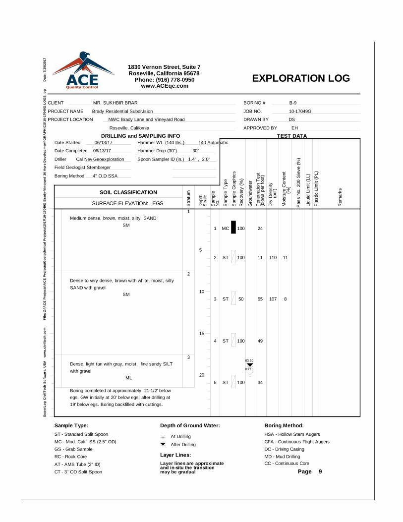
1Medium dense, brown, moist, silty SAND SM
2Dense to very dense, brown with white, moist, siltySAND with gravel SM
3Dense, light tan with gray, moist, fine sandy SILTwith gravel ML
Boring completed at approximately 21-1/2' belowegs. GW initially at 20' below egs; after drilling at19' below egs. Boring backfilled with cuttings.
1 MC 100 24
2 ST 100 11 110 11
3 ST 50 55 107 8
4 ST 100 49
5 ST 100 34
03:30
03:15
EXPLORATION LOG
Supe
rLog
Civ
ilTec
h So
ftwar
e, U
SA
ww
w.c
ivilt
ech.
com
File
: Z:\A
CE
Proj
ects
\AC
E Pr
ojec
ts\G
eote
chni
cal P
roje
cts\
2017
\10-
1704
9G B
rady
-Vin
eyar
d 36
Acr
e D
evel
opm
ent\G
RA
PHIC
S\10
-170
49G
LO
GS.
log
Dat
e: 7
/25/
2017
CLIENT MR. SUKHBIR BRAR
PROJECT NAME Brady Residential Subdivision
PROJECT LOCATION NWC Brady Lane and Vineyard Road
Roseville, California
JOB NO. 10-17049G
DRAWN BY DS
APPROVED BY EH
BORING # B-9
Date Started 06/13/17
Date Completed 06/13/17
Driller Cal Nev Geoexploration
Field Geologist Stemberger
Boring Method 4" O.D SSA
Hammer Wt. (140 lbs.) 140 Automatic
Hammer Drop (30") 30"
Spoon Sampler ID (in.) 1.4" , 2.0"
SURFACE ELEVATION: EGS
SOIL CLASSIFICATIONS
tratu
m
Dep
th
Sam
ple
Gro
undw
ater
(blo
ws
per f
oot)
Sam
ple
Type
Pen
etra
tion
Test
Moi
stur
e C
onte
nt
Pas
s N
o. 2
00 S
ieve
(%)
Rem
arks
Page
Dry
Den
sity
(pcf
)
1830 Vernon Street, Suite 7Roseville, California 95678
Phone: (916) 778-0950www.ACEqc.com
DRILLING and SAMPLING INFO
Sca
le
No.
Rec
over
y (%
)
(%
)
TEST DATA
Sam
ple
Gra
phic
s
Liqu
id L
imit
(LL)
Pla
stic
Lim
it (P
L)
Sample Type:ST - Standard Split SpoonMC - Mod. Calif. SS (2.5" OD)GS - Grab SampleRC - Rock CoreAT - AMS Tube (2" ID)CT - 3" OD Split Spoon
Depth of Ground Water:
At Drilling
After Drilling
Layer Lines:Layer lines are approximateand in-situ the transition may be gradual
Boring Method:HSA - Hollow Stem AugersCFA - Continuous Flight AugersDC - Driving CasingMD - Mud DrillingCC - Continuous Core
5
10
15
20
9
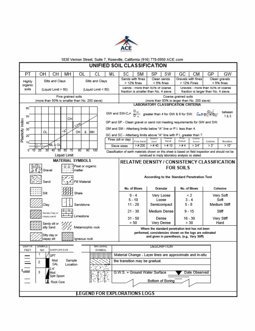
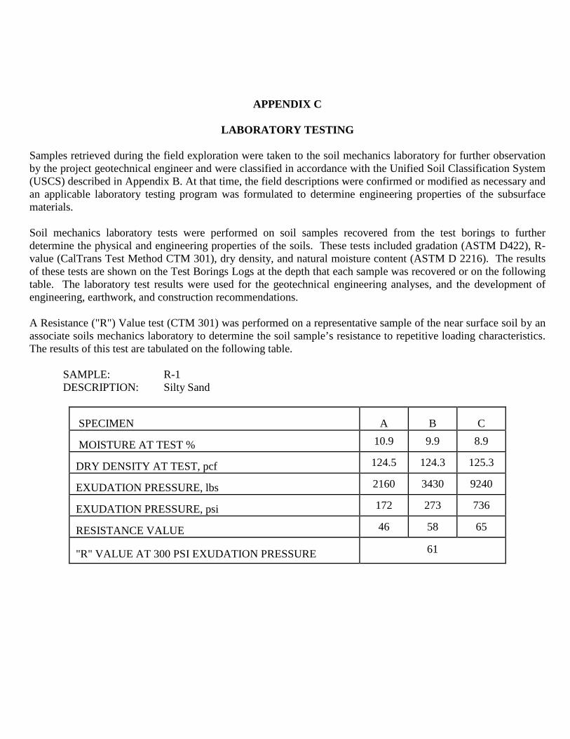
APPENDIX C
LABORATORY TESTING
Samples retrieved during the field exploration were taken to the soil mechanics laboratory for further observation by the project geotechnical engineer and were classified in accordance with the Unified Soil Classification System (USCS) described in Appendix B. At that time, the field descriptions were confirmed or modified as necessary and an applicable laboratory testing program was formulated to determine engineering properties of the subsurface materials. Soil mechanics laboratory tests were performed on soil samples recovered from the test borings to further determine the physical and engineering properties of the soils. These tests included gradation (ASTM D422), R-value (CalTrans Test Method CTM 301), dry density, and natural moisture content (ASTM D 2216). The results of these tests are shown on the Test Borings Logs at the depth that each sample was recovered or on the following table. The laboratory test results were used for the geotechnical engineering analyses, and the development of engineering, earthwork, and construction recommendations. A Resistance ("R") Value test (CTM 301) was performed on a representative sample of the near surface soil by an associate soils mechanics laboratory to determine the soil sample’s resistance to repetitive loading characteristics. The results of this test are tabulated on the following table.
SAMPLE: R-1 DESCRIPTION: Silty Sand
SPECIMEN
A
B
C
MOISTURE AT TEST % 10.9 9.9 8.9 DRY DENSITY AT TEST, pcf 124.5 124.3 125.3 EXUDATION PRESSURE, lbs 2160 3430 9240 EXUDATION PRESSURE, psi 172 273 736 RESISTANCE VALUE 46 58 65 "R" VALUE AT 300 PSI EXUDATION PRESSURE 61
APPENDIX D
GUIDE SPECIFICATIONS FOR EARTHWORK A. General Description
1. This item shall consist of all clearing and grubbing, removal of existing obstructions, preparation of the land to be filled, filling the land, spreading, compaction and control of the fill, and all subsidiary work necessary to complete the grading of the cut and fill areas to conform with the lines, grades and slopes as shown on the accepted plans.
2. The Geotechnical Engineer is not responsible for determining line, grade elevations or slope gradients. The property owner or his representative shall designate the party that will be responsible for those items of work.
B. Geotechnical Report
1. The Geotechnical Report has been prepared for this project by ACE Quality Control, Roseville, California, (916-742-5096). This report was for design purposes only and may not be sufficient to prepare an accurate bid. A copy of the report is available for review at ACE's office.
2. Contents of these guide specifications shall be integrated with the Geotechnical Report of which they are a part and shall not be used as a self-contained document. Where a conflict occurs between these guide specifications and the conclusions and recommendations contained in the report, then the conclusions and recommendations shall take precedence and these guide specifications adjusted accordingly.
C. Site Preparation
1. Clearing Area(s) to be Filled: All trees, brush, logs, rubbish and other debris shall be removed and disposed of so as to leave the areas that have been disturbed with a neat appearance. Underground structures shall be removed or may be crushed in place upon approval by the Geotechnical Engineer. Excavations and depressions resulting from the removal of the above items shall be cleaned out to firm undisturbed soil and backfilled with suitable materials in accordance with the specifications contained herein. Stockpiles of clean soil may be reused as filled material provided the soil is free of significant vegetation, debris, rubble and rubbish and is approved by the Geotechnical Engineer.
2. Surfaces upon which fill is to be placed, as well as subgrades of building pad(s) left at existing grade, shall have all organic material removed; or, with permission of the Geotechnical Engineer, closes cut and remove vegetation and thoroughly disc and blend the remaining nominal organics into the upper soil. Discing must be thorough enough so that no concentrations of organics remain, which may require re-discing or cross-discing several times.
3. Organic laden material removed per paragraph C.2. above, may be used as fill in landscaped areas provided that the material shall not extend closer than ten (10) feet to any structure, shall not exceed two (2) feet in thickness or be used where the material could, in the opinion of the Geotechnical Engineer, create a slope stability problem, and shall be compacted to at least eighty-two (82) percent relative compaction per ASTM Test Designation D 1557. Alternatively, the organic laden material may be hauled off-site and suitably disposed of.

4. Upon completion of the organic removal, exposed surface shall be plowed or scarified to a depth of at least six (6) inches, and until the surface is free from ruts, hummocks, or other uneven features which would tend to prevent uniform compaction by the equipment to be used. Where vegetation has been close cut and removed and remaining organics blended with the upper soil, further scarifying may not be necessary. Where fills are to be placed on hill slopes, scarifying shall be to depths adequate to provide bond between fill and fill foundation. Where considered necessary by the Geotechnical Engineer, (typically where the slope ratio of the original ground is steeper than five (5) horizontal to one (1) vertical), the ground surface shall be stepped or benched to achieve this bond. Vertical dimension of the required benches shall be as determined by the Geotechnical Engineer, based upon location, degree and condition of the hill slope.
5. After the foundation for the fill has been cleared and scarified, it shall be disced or bladed until it is uniform and free from large clods, uniformly moisture conditioned to the range specified by the Geotechnical Engineer, and compacted to not less than [refer to report -- if not recommended, use 90] percent of maximum dry density as determined by ASTM D 1557, or to such other density as may be determined appropriate for the materials and conditions and acceptable to the Geotechnical Engineer and the owner or his representative.
D. Fill Materials
1. Materials for fill shall consist of material approved by the Geotechnical Engineer.
2. The materials used for fill shall be free from organic matter and other deleterious substances and shall not contain rocks, clods, lumps or cobbles exceeding four (4) inches in greatest dimension with not more than fifteen (15) percent larger than two and one-half (2-1/2) inches.
3. Imported materials to be used for fill shall be non-expansive [typically, have a plasticity index not exceeding twelve (12)], shall be of maximum one (1) inch size, and shall be tested and approved by the Geotechnical Engineer prior to commencement of grading and before being imported to the site.
4. The Contractor shall notify the Geotechnical Engineer at least four (4) working days in advance of the Contractor's intention to import soil; shall designate the borrow area; and, shall permit the Geotechnical Engineer to sample the borrow area for the purposes of examining the material and performing the appropriate tests to evaluate the quality and compaction characteristics of the soil. Compaction requirements for the material shall be based upon the characteristics of the material as determined by the Geotechnical Engineer.
E. Placement of Fill
1. The selected fill material shall be placed in level, uniform layers (lifts) which, when compacted, shall not exceed six (6) inches in thickness. Water shall be added to the fill or the fill allowed to dry as necessary to obtain fill moisture content at which compaction as specified can be achieved. Each layer shall be thoroughly mixed during the spreading to obtain uniformity of moisture in each layer.
2. The fill material shall be compacted within the appropriate moisture content range (typically
optimum to slightly above the optimum) as determined by the Geotechnical Engineer for the soil(s) being used.
3. Each layer of fill shall be compacted to not less than [refer to report; if not recommended, use 90] percent of maximum dry density as determined by ASTM Test Designation D 1557. Compaction equipment shall be of such design that it will be able to compact the fill to the
specified density. Compaction shall be accomplished while the fill material is within the specified moisture content range. Compaction of each layer shall be continuous over its entire area and the compaction equipment shall make sufficient trips to insure that the required density has been obtained. No ponding or jetting is permitted.
4. If work has been interrupted for any reason, the Geotechnical Engineer shall be notified by the contractor at least two (2) working days prior to the intended resumption of grading.
F. Geotechnical Engineer
1. Owner is retaining Geotechnical Engineer to make observations and tests to determine general compliance with Plans and Specifications, to verify expected or unexpected variations in subsurface conditions, and to give assistance in appropriate decisions. Cost of Geotechnical Engineer will be borne by the Owner, except costs incurred for re-tests and/or re-observations caused by failure of the Contractor to meet specified requirements will be paid by the Owner and back charged to Contractor.
G. Observation and Testing
1. Field density tests shall be made by the Geotechnical Engineer or his representative of the compaction of each layer of fill. Density tests shall be taken in the compacted material below any surfaces disturbed by the construction equipment. When these tests indicate that the density of any layer of fill or portion thereof is below the required density or moisture content, the particular layer or portion shall be reworked until the required density or moisture content has been obtained.
2. All aspects of the site earthwork shall be observed and tested as deemed necessary by the
Geotechnical Engineer or his representative so that he can render a professional opinion of the completed fill for substantial compliance with plans and specifications and design concepts. The grading contractor shall give the Geotechnical Engineer at least two (2) working days’ notice prior to beginning any site earthwork to allow proper scheduling of the work.
H. Seasonal Limits
1. No fill material shall be placed, spread or compacted during unfavorable weather conditions. When work is interrupted by heavy rain, fill operations shall not be resumed until the Geotechnical Engineer or his representative indicates that the moisture content and density of the previously placed fill are as specified.
GRADING DETAILS (on following pages)
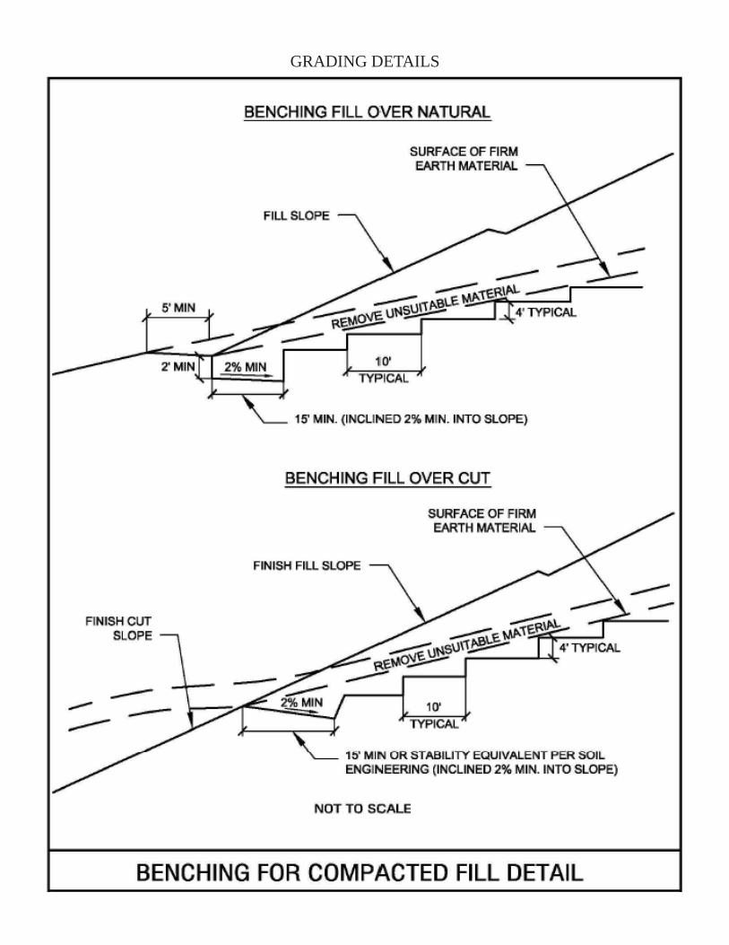
GRADING DETAILS