Embed Size (px)
Citation preview
APPENDIX G TECHNICAL SPECIFICATIONS
SECTION 01 01 0
SUMMARY OF WORK
SECTION 01010
SUMMARY OF WORK
PART 1 - GENERAL
1.1 Scope This section includes:
Scope of Work Definitions and Abbreviations Drawings Work by Others Conmactors Use of Site Conmacto~s Use of Facilities Work Sequence Work Plan Submittals
1.2 Scope of Work The Contractor shall furnish all labor, materials, equipment and tools to perform operations in connection with the construction of two (2) panel closure systems for each panel, one of each to be installed in the air intake drift and the air exhaust drift of a wasteemplacement panel, as shown on the drawings and called for in these specifications.
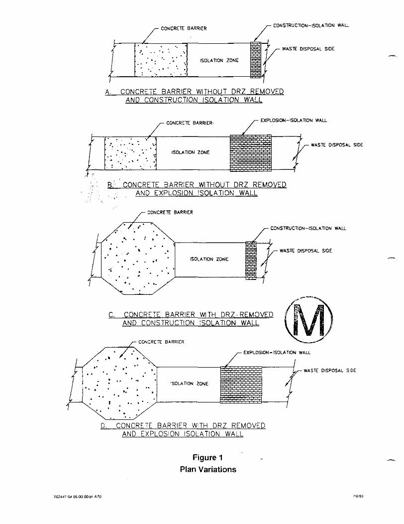
Four (4) possible arrangements of the concrete barrier and isolation walls are shown on the attached Figure 1 "Plan Variations." The specific requirements for the panel closure system will be determined by the Westinghouse WID prior to the time of installation and will be defined in the contract documents.
Concrete barrier with disturbed rock zone @RZ) removal up through clay seam G and down through marker bed 139 (MB 139) in combination with a construction isolation wall (Sketch A).
Concrete barrier with DRZ removal in combination with an explosion isolation wall (Sketch B.)
Concrete barrier without DRZ removal in combination with construction isolation wall (Sketch C).
Concrete barrier without DRZ removal in combination with an explosion isolation wall (Sketch D).
CONCRETE BARRIER CONSTRUCTION-ISOLATION WALL
: WASTE DISPOSAL SlDE . . . . . . . . . . . .. ' . ISOLATION ZONE
. . . . .
A. CONCRETE BARRIER WITHOUT DRZ REMOVED AND CONSTRUCTlON ISOLATION WALL
,- CONCRETE BARRIER- /- EXPLOSION-ISOLATION W A U
. . . . . . . ., WASTE DISPOSAL SIDE . . . . . .. - . ISOLATION ZONE . . . . . . . . . . . . . .
,+ . B. CONCRETE BARRIER WITHOUT DRZ REMOVED , .
, . 4 .
AND EXPLOSION ISOLATION WALL
ONCRETE BARRIER
CONSTRUCTION-ISOLATiON WALL
WASTE DISPOSAL SIDE
ISOLATION ZONE . . . . . .
C. CONCRETE BARRIER WITH D R Z - REMOVED AND CONSTRUCTION ISOLATION WALL
EXPLOSIDN-ISOLATION WALL
WASTE DISPOSAL SIDE
'SOLATION ZONE
D CONCRETE BARRIER WITH DRZ REMOVED AND EXPLOSION ISOLATION WALL
Figure 1
Plan Variations
A
The scope of work shall include but not be limited to the following units of work:
Develop work plan, health and safety plan (HASP) and contractors quality control plan (CQCP)
Prepare and submit all plans requiring approval
Mobilize to site
Coordinate conshuction with operations
Perform the following for the air intake entry and the air exhaust entry. - Excavate the surface preparation for the explosion (or construction) isolation wall - Construct the explosion (or construction) isolation wall - Excavate the DRZ if required by contract - InstaII the form work for the concrete barrier - Place concrete for the concrete barrier - Grout the interface of concrete barrierhack wall - Provide contact grouting along the contact surface (if required by the engineer)
Clean up construction areas in underground and above ground - 4" - . . Submit all required record documents
Demobilize from site
1.3 Definitions and Abbreviations
Definitions
Contact-handled waste-Contact-handled defense transuranic (TRU) waste with a surface dose rate not to exceed 200 millirem per hour.
Concrete barrier-A barrier placed in the access drifts of a panel to restrict the mass flow rate of volatile organic compounds (VOC).
Concrete block--Concrete used for construction of either an explosion-isolation wall or a construction-isolation wall.
Construction-isolation wall-A wall immediately adjacent to the panel waste-emplacement area that is made of concrete block, with mortar or of steel to isolate construction personnel from coming into contact with the waste.
-Plastic deformation of salt under deviatoric stress.
Design migration limit-A mass flow rate that results in an exposure of the affected individual that is at least 1 order of magnitude below the health-based exposure levels for VOCs during the Waste Isolation Pilot Plant (WlPP) operational period.
Disturbed rock zone ( D R Z t A zone surrounding underground excavations where stress redistribution occurs with anendant dilation and fracturing.
Explosion-isolation wall-A concrete-block wall adjacent to the panel waste-emplacement area with mortar that can sustain the pressure and temperature transients of a methane explosion.
Health-based concentration level-The annual average concentration level for a VOC in air that must not be exceeded at the point of compliance.
Health-based mimation limit-The mass flow rate of a VOC from all closed panels that results in the health-based concentration level at the point of compliance.
Hydration temperature-The transient temperature developed by a cementitious material due to the hydration of the cement.
Interface grouting4routing performed through grout boxes and pipe lines to fill the void at the concrete barrierback-wall interface.
Methane explosion--A postulated deflagration caused by the buildup of methane gas to explosive levels.
Partial closure-The process of rendering a part of the hazardous waste management unit in the underground repository inactive and closed according to approved facility closure plans. The partial-closure process is considered complete after partial-closure activities are performed in accordance with approved Resource Conservation and Recovery Act (RCRA) partial closure plans.
Point of com~liance-The operating point of compliance for VOC health-based exposure levels at the WPP, which is the WIPP site boundruy.
Remote-handled waste-Any of the various forms of high beta-gamma defense TRU waste;. requiring remote-handling due to a surface dose rate exceeding 200 millirem per hour.
'; . ' I ,
Standard barrier-A concrete barrier emplaced into the panel-access drifts without major ' . ,
excavation of the surrounding rock.
- Volatile Oreanic Com~ound (VOC)-Any VOC comprising the land-disposal-restricted indicator VOC constituents in the WIPP waste inventory.
Westinehouse-Westinghouse Electric Corporation, Waste Isolation Division (WID) as the construction management authority.
ACI American Concrete Institute AISC American Institute for Steel Construction ANSI American National Standards Institute ASTM American Society for Testing and Materials AWS American Welding Society CFR Code of Federal Regulations DOE U.S. Department of Energy DRZ disturbed rock zone EP A U.S. Environmental Protection Agency MB 139 Marker Bed 139 MSHA U.S. Mining Safety and Health Administration NM AC New Mexico Administrative Code NMED New Mexico Environment Department RCRA Resource Conservation and Recovery Act SMC Salado Mass Concrete US ACE U.S. Army Corps of Engineers WID Waste Isolation Division WIPP Waste Isolation Pilot Plant
1.4 List of Drawings The following drawings are made apart of this specification:
762447-El Panel closure system, air intake and exhaust drifts, title sheet 762447-E2 Panel closure system, underground waste-emplacement panel plan 762447-E3 Panel closure system, air intake drift, construction details 762447-E4 Panel closure system, air exhaust drift construction details 762447-E5 Panel closure system, construction and explosion walls, construction details 762447-E6 Panel closure system, air intake and exhaust drifts, grouting and miscellaneous
details
1.5 Work by Others
Survey
All survey work to locate the barriers and walls, control and confirm excavation, and A
complete the work will be supplied by Westinghouse. All survey measurements for record purposes will also be performed by Westinghouse. The Contractor shall be responsible for verifying the excavation dimensions to develop the form work to fit the excavation.
Excavation
The Westinghouse WID may elect to perform certain portions of the work, notably the excavation. The work performed by the Westinghouse will be defined prior to the contract.
1.6 Contractor's Use of Site
Site Conditions
The site is located near Carlsbad, New Mexico, as shown on the site location maps and the title sheet drawing. The underground arrangements and location of the WIPP waste- emplacement panels are shown on the plan view drawing. The work described above is to conshuct the concrete barriers in the air intake and exhaust drifts of one of the panels upon completion of the disposal phase of that panel. The waste-emplacement panels are located approximately 2,150 feet below the ground surface. The Contractor shall visit the site and become familiar with the site and site conditions prior to preparing his bid proposal.
Contractor's Use of Site - Areas ,at the ground surface will be designated for the Contractor's use in assembling and storing his equipment and materials. The Contractor shall utilize only those areas designated.
Limited space within the underground area will be designated for the Contractor's use for storage of material and setup of equipment.
Coordination of Contractor's Work
The Contractor is advised that on-going waste emplacement and excavation operations are being conducted throughout the period of conshuction of the panel barrier system. The Contractor shall coordinate his construction operations with that of the waste emplacement and mining operations. All coordination shall be through Westinghouse WID.
1.7 Contractor's Use of Facilities Existing facilities at the site which are available for use by the Contractor are:
WIPP roadheader Waste shaft conveyance Salt skip hoist (1) 20 ton forklift
-. (1) 40 ton forklift 460 volt AC, 3 phase power Water (underground, at waste shaft only) (above ground, at location designated by Engineer)
Additional information on these facilities is presented in Section 02010.
1.8 Work Sequence Work Sequence shall be as shown on the drawings and directed by Westinghouse WID .
1.9 Work Plan The Contractor shall prepare and submit for approval by Westinghouse WID a Work Plan fully describing his proposed consrmction operation. The work plan shall define all proposed equipment. The work plan shall also include the method of excavation, grouting, and pumping concrete. The work plan shall also contain such items as control of surface dust emissions. No work shall be performed prior to approval of the Work Plan.
1.10 Health and Safety Plan (HASP) The Contractor shall obtain, review, and agree to applicable portions of the existing WIPP Safety Manual, WP 12-1. The Contractor shall prepare and submit for approval to Westinghouse, a project-specific HASP taking into account all applicable sections of the WIPP Safety Manual. The Contractor shall also perform a Job Hazard Analysis in - accordance with WP 12-1 11.
1.11 Contractor Quality Control Plan (CQCP) The Contractor shall prepare and submit for approval to Westinghouse a CQCP identifying all personnel and procedures to produce an end product which complies with the contract requirements. The CQCP shall comply with all Westinghouse WID requirements and Section 01400, Contractor Quality Control, of this specification.
1.12 Submittals Submittals shall be in accordance with Westinghouse WID Submittal Procedures and as required by the individual specifications.
PART 2 - PRODUCTS
(Not used)
PART 3 - EXECUTION
(Not Used)
- PI'111-17-95 (12:401NP~62417:OIOlO.rpc
SECTION 01 090
REFERENCE STANDARDS
SECTION 01090
REFERENCE STANDARDS
PART 1 - GENERAL
1.1 Scope This section includes:
Provision of Reference Standards at Site.
Acronyms used in Contract Documents for Reference Standards. Standards.
1.2 Quality Assurance
Source of Reference
For products or workmanship specified by association, trade, or Federal Standards, comply with requirements of the standard, except when more rigid requirements are specified or are required by applicable codes.
- Conform to reference by date of issue current on the date of the owner-contractor agreement.
The Contractor shall obtain copy of the standards referenced in the individual specification sections. Maintain a copy at jobsite during submittals, planning, and progress of the specific work, until completion of work.
Should specified reference standards conflict with the contract documents, request clarification from the Engineer before proceeding.
1.3 Schedule of References Various publications are referenced in other sections of the specifications to establish requirements for the work. These referenced are identified by documents number and title. The addresses of the organizations whose publications are referenced are listed below.
ACI ACI International P.O. Box 19150 Detroit,MI 48219-0150 Ph: 313-532-2600 Fax: 313-533-4747
AISC
ANSI
API
ASTM
AWS
CFR
American Institute of Timber Construction 7012 So. Revere Parkway, Suite 140 Englewood, CO 801 12 Ph: 303-792-9559 F a : 303-792-0669
American Institute of Steel Construction One E. Wacker Dr., Suite 3100 Chicago, IL 606Q1-2001 Ph: 312-670-2400 F a : 312-670-5403
American National Standards Institute 1 1 West 42nd St. New York NY 10036 pH: 212-642-4900 Fax: 212-302-1286
American Petroleum Institute 1220 L. St, NW Washington, DC 20005 Ph: 202-682-8375 F a : 202-962-4776
American Society for Testing and Materials 1916 Race St Philadelphia, PA 19103 Ph: 610-832-9585 Fax: 215-977-9679
American Welding Society 550 LeJeune Road Miami, FL 33135 Ph: 800-443-9353 Fax: 305-443-7559
Code of Federal Regulations Government Printing Office Washington, DC 20402 Ph: 202-783-3238 Fax: 202-223-7703
NTIS
PCA
US ACE
Environmental Protection Agency Public Information Center 401 M St, SW Washington, DC 20460 Ph: 202-260-2080,
FTM-ST0 Federal Test Method Standards Standardization Documents Order Desk Bldg. 4D 700 Robbins Ave. Philadelphia, PA 191 11-5094 Ph: 215-697-2179 Fax: 215-697-2978
NRMCA National Ready-Mixed Concrete Association 900 Spring St. Silver Spring, MD 20910 Ph: 301-587-1400 Fax: 301-585-4219 .__
i - .. . National Technical Information Service pt $:, . U.S. Department of Commerce , Springfield, VA 22161 , ,
~''''.'. : k , j :: ; . , , i ! I
(703) 487-4650 ; , $, , , ,
L. ';/ - . , -'
Portland Cement Association 5420 Old Orchard Road Skokie, IL 60077
U.S. Army Corps of Engineers U.S. Army Engineer Waterway Experiment Station ATTN: Technical Report Distribution Section, Services Branch, TIC 3909 Halls Ferry Rd. Vicksburg, MS 39180-6199 Ph: 601-634-2355 Fax: 60 1-634-2506
WID Westinghouse Elechic Corporation Waste Isolation Division Carlsbad. New Mexico 88221
End of Section
SECTION 01 400 CONTRACTOR QUALITY CONTROL
SECTION 01400
CONTRACTORQUALITYCONTROL
PART 1 - GENERAL
1.1 Scope This section includes:
Contractor Quality Cone01 Plan (CQCP) Reference Standards Quality Assurance Tolerances Testing Services Inspection Services Submittals
1.2 Related Sections
01090 - Reference Standards - 01600 - Material and Equipment 02222 - Excavation 02722 - Grouting 03 100 - Concrete Formwork 03300 - Cast-in-Place Concrete 04100 - Mortar 04300 - Unit Masonry System
1.3 Contractor Quality Control Plan The Contractor shall prepare and submit for approval by Westinghouse WID, a Quality Control Plan, as described in Section 3.2. No work shall be performed prior to approval of the Contractor's Quality Control Plan.
1.4 References and Standards Refer to individual specification sections for standards referenced therein, and to Section 01090 - Reference Standards for general listing.
Standards referenced in this section are as follows:
ASTM C1077-95a Practice for Laboratories Testing Concrete and Concrete Aggregates for Use in Construction and Criteria for Laboratory Evaluation
ASTM C1093-88 Practice for Accreditation of Testing Agencies for Unit Masonry A
ASTM E329-95 Practice for Use in the Evaluation of Inspection and Testing Agencies as Used in Construction
ASTM E543-95 Practice for Determining the Qualification of Nondestructive Testing Agencies
ASTM E548-94 Practice for Preparation of Criteria for Use in the Evaluation of Testing Laboratories and Inspection Bodies
1.5 Quality Assurance
Monitor quality control over suppliers, manufacturers, products, services, site condition I and workmanship, to produce work of specified quality Comply with specified standards as minimum quality for the work except where more stringent tolerances, codes, or specified requirements indicate higher standards or more precise workmanship Perform work by persons qualified to produce required and specified quality Verify that field measurements are as indicated on shop drawings Secure products in place with positive anchorage devices designed and sized to withstand stresses, vibration, physical distortion, or disfigurement.
1.6 Tolerances - Monitor excavation fabrication and installation tolerance control of work and products to produce acceptable work. Do not permit tolerances to accumulate.
Adjust products to appropriate dimensions; position before securing products in place.
1.7 Testing Services Unless otherwise indicated by Westinghouse WID, the Contractor shall employ an independent fm to perform the testing services and other services specified in the individual specification sections, and as required by Westinghouse WID. Testing and source quality control may occur on or off the project site.
The testing laboratory shall comply with applicable sections of the reference standards and shall be authorized to operate in the state in which the project is located.
Testing equipment shall be calibrated at reasonable intervals with devices of an accuracy traceable to either the National Bureau of Standards or accepted values of natural physical constants.
- 1.8 Inspection Services The Contractor shall employ an independent firm to perform inspection services as a supplement to the Contractor's quality control as specified in the individual specification sections, and as required by Westinghouse WID. Inspection may occur on or off the project site.
The inspection f i shall comply with applicable sections of the reference standards.
1.9 Submittals The Contractor shall submit a Contractors' Quality Control Plan as described herein.
Prior to start of work, the Contractor shall submit for approval, the testing laboratory name, address, telephone number and name of responsible officer of the fm. He shall also submit a copy of the testing laboratory compliance with the reference ASTM standards, and a copy of report of laboratory facilities inspection made by Materials Reference Laboratory of National Bureau of Standards with memorandum of remedies of any deficiencies reported by the inspection.
Prior to start of work, the Contractor shall submit for approval the inspection firm name, address, telephone number and name of responsible officer of the firm. He shall also submit the personnel proposed to perform the required inspection, along with their individual qualifications and certifications (Example: Certified AWS Welding Inspector.)
PART 2 - PRODUCTS
Not used.
PART 3 - EXECUTION
3.1 General The Contractor is responsible for quality control and shall establish and maintain an effective quality control system. The quality control system shall consist of plans, procedures, and organization necessary to produce an end product which complies with the contract requirements. The system shall cover all construction operations, both on site and off site, and shall be keyed to the proposed construction sequence. The project superintendent will be held responsible for the quality of work on the job. The project superintendent in this context shall mean the individual with the responsibility for the overall management of the project including quality and production.
3.2 Quality Control Plan
3.2.1 General The Contractor shall furnish for review and approval by Westinghouse WID, not later than 30 days after receipt of notice to proceed, the Contractor Quality Control (CQC) Plan proposed to implement the requirements of the Contract. The plan shall identify personnel, procedures, control, insuuctions, test, records, and forms to be used. Consmction will be permitted to begin only after acceptance of the CQC Plan.
3.22 Content of the CQC Plan The CQC Plan shall include, as a minimum, the following to cover all construction operations, both on site and off site, including work by subcontractors, fabricators, suppliers, and purchasing agents:
A description of the quality control organization, including a chart showing lines of authority and acknowledgment that the CQC staff shall implement the control system for all aspects of the work specified. The staff s h d include a CQC System Manager who shall report to the project superintendent
The name, qualifications (in resume format), duties, responsibilities, and authorities of each person assigned a CQC function.
Description of the CQC System Manager's responsibilities and delegation of authority to - adequately perform the functions of the CQC System Manager, including authority to stop work which is not in compliance with the contract. The CQC System Manager shall issue letters of direction to all other various quality control representatives outlining duties, authorities, and responsibilities.
Procedures for scheduling, reviewing, certifying, and managing submittals, including those of subcontractors, off site fabricators, suppliers, and purchasing agents. These procedures shall be in accordance with Westinghouse WID Submittal Procedures.
Control, verification, and acceptance testing procedures for each specific test to include the test name, specification paragraph requiring test, feature of work to be tested, test frequency, and person responsible for each test. (Laboratory facilities will be subject to approval by Westinghouse WID.)
Procedures for tracking construction deficiencies from identification through acceptable corrective action. These procedures will establish verification that identified deficiencies have been corrected.
Reporting procedures, including proposed reporting formats.
-. A list of the definable features of work. A definable feature of work is a task which is separate and distinct fiom other tasks and has separate control requirements. It could be identified by different trades or disciplines, or it could be work by the same trade in a different environment Although each section of the specifications may generally be considered as a definable feature of work, there are frequently more than one definable feature under a particular section. This list will be submitted to Westinghouse WID for approval.
3.23 Acceptance of Plan Acceptance of the Connactor's plan is required prior to the start of consmction. Acceptance is conditional and will be predicated on satisfactory performance during the consmction. The Owner reserves the right to require the Contractor to make changes in his CQC Plan and operations including removal of personnel, as necessary, to obtain the quality specified.
3.2.4 Notification of Changes After acceptance of the CQC Plan, the Contractor shall notify Westinghouse WID in writing of any proposed change. Proposed changes are subject to acceptance by Westinghouse WID.
3.3 Quality Control Organization
3.3.1 General The requirements for the CQC organization are a CQC System Manager and sufficient number of additional qualified personnel supplemented by independent testing and inspection firms as required by the specifications, to ensure contract compliance. The Contractor shall provide a CQC organization which shall be at the site at all times during progress of the work and with complete authority to take any action necessary to ensure compliance with the contract. All CQC staff members shall be subject to acceptance by Westinghouse WID.
33.2 CQC System Manager The Contractor shall identify as CQC System Manager an individual within his organization at the site of the work who shall be responsible for overall management of CQC and have the authority to act in all CQC matters for the Contractor. The CQC System Manager shall be a graduate engineer, with a minimum of five years construction experience on construction similar to this contract. This CQC System Manager will be employed by the prime Contractor. The CQC System Manager shall be assigned no other duties. An alternate for the CQC System Manager will be identified in the plan to serve in the event of the System Manager's absence. The requirements for the alternate will be the same as for the designated CQC System Manager.
3.3.3 CQC Personnel In addition to CQC personnel specified elsewhere in the contract, the Contractor shall provide as part of the CQC organization specialized personnel or thud party inspectors to assist the CQC System Manager. These individuals shall be employed by the prime Contractor; be
responsible to the CQC System Manager; have the necessary education and/or experience. - These individuals shall have no other duties other than quality control.
3.3.4 Organizational Changes The Contractor shall maintain his CQC staff at full strength at all times. When it is necessary to make changes to the CQC staff the Contractor shall revise the CQC Plan to reflect the changes and submit the changes to Westinghouse WID for acceptance at the Contractors' expense. . ,
3.4 Tests ! I t
3.4.1 Testing Procedure The Contractor shall perform specified or required tests to verify that control measures ak adequate to provide a product which conforms to contract requirements. Upon request, the Contractor shall furnish to Westinghouse WID duplicate samples of test specimens for possible testing by Westinghouse WID. Testing includes operation andlor acceptance tests when specified. The Contractor shall procure the services of an approved testing laboratory. The Contractor shall perform the following activities and record and provide the following data:
Verify that testing procedures comply with contract requirements.
Verify that facilities and testing equipment are available and comply with testing standards. -.
Check test insmment calibration data against certified standards.
Verify that recording forms and test identification control number system, including all of the test documentation requirements, have been prepared.
Results of all tests taken, both passing and failing tests, will be recorded on the CQC report for the date taken. Specification paragraph reference, location where tests were taken, and the sequential control number identifying the test will be given. If approved by Westinghouse WID, actual test reports may be submitted later with a reference to the test number and date taken. An information copy of tests performed by an off site or commercial test facility will be provided directly to Westinghouse WID. Failure to submit timely test reports as stated may result in nonpayment for related work performed and disapproval of the test facility for this contract.
3.5 Testing Laboratory The testing laboratory shall provide qualified personnel to perform specified sampling and testing of products in accordance with specified standards, and ascertain compliance of materials and mixes with requirements of Contract Documents. The testing laboratory shall promptly notify Westinghouse WID and Contractor of any observed irregularities or non- conformance of Work or Products.
- Reports indicating results of tests, and compliance (or noncompliance) with the contract documents will be submitted in accordance with Westinghouse WID submittal procedures.
The Contractor shall cooperate with the independent testing f m , furnish samples, storage, safe access, and assistance by incidental labor as required. Testing by the independent firm does not relieve the contractor of the responsibility to perform the work to the contract requirements.
The laboratory may not:
Release, revoke, alter, or enlarge on requirements of the contract Approve or accept any portion of the work Assume any duties of the Contractor.
The laboratory has no authority to stop the work.
3.6 Inspection Services The inspection firm shall provide qualified personnel at site to supplement the Contractor's Quality Control Program to perform specified inspection of Products in accordance with specified standards. He shall ascertain compliance of materials and mixes with requirements of Contract Documents, and promptly notify the CQC System Manager, Westinghouse WID and the Contractor of observed irregularities or non-confoxmance of Work or Products. The inspector does not have the authority to stop the work. The inspector shall refer such cases to the CQC System Manager who has the authority to stop work (see Section 3.2.2).
Reports indicating results of the inspection and compliance (or noncompliance) with the contract documents will be submitted in accordance with Westinghouse WID submittal procedures.
The Contractor shall cooperate with the independent inspection firm, furnish samples, storage, safe access and assistance by incidental labor, as requested.
Inspection by the independent firm does not relieve the Contractor of the responsibility to perform the work to the contract requirements.
3.7 Completion Inspection
3.7.1 Pre-Final Inspection At the completion of all work the CQC System Manager shall conduct an inspection of the work and develop a "punch list" of items which do not conform to the approved drawings and specifications. Once this is accomplished the Contractor shall notify Westinghouse WID that the facility is complete and is ready for the "Prefinal" inspection. Westinghouse WID will perform this inspection to verify that the facility is complete. A "Final Punch List" will be developed as a result of this inspection. The Contractor's CQC System Manager shall ensure
that all items on this list have been corrected and notify Westinghouse WID so that a "Fial" inspection can be scheduled. Any items noted on the "Fial" inspection shall be corrected in a timely manner. These inspections and any deficiency corrections required by this paragraph will be accomplished within the time slated for completion of the entire work.
3.7.2 Final Acceptance Inspection The final acceptance inspection will be formally scheduled by Westinghouse WID based upon notice from the Contractor. This notice will be given to Westinghouse WID at least 14 days prior to the final acceptance inspection and must include the Contractor's assurance that all specific items previously identified to the Contractor as being unacceptable, along with all remaining work performed under the contract, will be complete and acceptable by the date scheduled for the final acceptance inspection.
3.8 Documentation The Contractor shall maintain current records providing factual evidence that required quality control activities and/or tests have been performed. These records shall include the work of subcontractors and suppliers and shall be on an acceptable form that includes, as a minimum, the following information:
Contractor/subcontractor and their area of responsibility.
Operating plant/equipment with hours worked, idle, or down for repair.
Work performed each day, giving location, description, and by whom.
Test and/or quality control activities performed with results and references to specifications/drawings requirements. List deficiencies noted along with corrective action.
Quantity of materials received at the site with statement as to acceptability, storage, and reference to spec51cations/drawings requirements.
Submittals reviewed, with contract reference, by whom, and action taken.
Off-site surveillance activities, including actions taken.
Instructions givedreceived and conflicts in plans and/or specifications.
Contractor's verification statement.
These records shall indicate a description of trades working on the project; the number of personnel working: weather conditions encountered; and any delays encountered. These records shall cover both conforming and deficient features and shall include a statement that equipment and materials incorporated in the work and workmanship comply with the contract. The original and one copy of these records in report form shall be furnished to Westinghouse
WID daily. Reports shall be signed and dated by the CQC System Manager. The report from the CQC System Manager shall include copies of test reports and copies of reports prepared by all subordinate quality control personnel.
3.9 Notification of Noncompliance Westinghouse WID will notify the Contractor of any detected noncompliance with the foregoing requirements. The Contractor shall take immediate corrective action after receipt of such notice. Such notice, when delivered to the Contractor at the worksite, shall be deemed sufficient for the purpose of notification. I€ the Contractor fails or refuses to comply promptly, Westinghouse WID may issue an order stopping all or part of the work until satisfactory corrective action has been taken. No part of the time lost due to such stop orders shall be made the subject of claim for extension of time or for excess costs or damages by the Contractor.
SECTION 01 600 MATERIAL AND EQUIPMENT
SECTION 01600
MATERIAL AND EQUIPMENT
PART 1 - GENERAL
1.1 Scope This section includes:
Equipment Products Transportation and handling Storage and protection Substitutions
1.2 Related Sections
01010 - Summary of Work 01400 - Contractor Quality Control 02010 - Mobilization and Demobilization 02222 - Excavation 02722 - Grouting . 03100 - Concrete Fomwork 03300 - Cast-in-Place Concrete 04100 - Mortar 04300 - Unit Masonry System
1.3 Equipment The Contractor shall specify his proposed equipment in the Work Plan. Power equipment for use underground shall be either electrical or diesel engine driven. All diesel engine equipment shall be certified for use underground.
1.4 Products The Contractor shall specify in the Work Plan, or in subsequently required submittals the proposed products including, but not limited to the grout mix and its components, concrete mix and its components, mortar mix and its components, formwork, and masonry. The proposed products shall be supported by laboratory test results as required by the specifications. All products shall be subject to approval by Westinghouse WID.
1.5 Transportation and Handling
Transport and handle products in accordance with manufacturer's instructions.
Promptly inspect shipments to ensure that products comply with requirements, quantities are correct, and products are undamaged.
Provide equipment and personnel to handle products by methods to prevent soiling, disfigurement, or damage.
1.6 Storage and Protection
Store and protect products in accordance with manufacturers' insmctions.
Store with seals and labels intact and legible.
Store sensitive products in weather tight, climate controlled, enclosures in an environment favorable to product.
For exterior storage of fabricated products, place on doped supports above ground.
Cover products subject to deterioration with impervious sheet covering. Provide ventilation to prevent condensation and degradation of products. -.
Store loose granular materials on solid flat surfaces in a well-drained area. Prevent mixing with foreign matter.
Provide equipment and personnel to store products by methods to prevent soiling, disfigurement, or damage.
Arrange storage of products to permit access for inspection. Periodically inspect to verify products are undamaged and are maintained in acceptable condition.
, . 1.7 Substitutions
1.7.1 Equipment Substitutions The Contractor may substitute equipment for that proposed in the Work Plan subject to Westinghouse WID'S approval. The Contractor shall demonstrate the need for the substitution, and the applicability of the proposed substitute equipment.
1.7.2 Product Substitutions The Contractor may not substitute products after the proposed products have been approved by Westinghouse WID unless he can demonstrate that the supplier/source of that product no longer exists in which case he shall submit alternate products with lab test results to
- Westinghouse WID for approval. In the case that product is a component in a mix, the Contractor shall perform rnix testing using that component and submit laboratory test results.
PART 2 - PRODUCTS
Not used.
PART 3 - EXECUTION Not used.
End of section.
SECTION 0201 0 MOBILIZATION AND DEMOBILIZATION
SECTION 02010
MOBILIZATION AND DEMOBILIZATION
PART 1 - GENERAL
1.1 Scope This section includes:
Mobilization of equipment and facilities to site Conwactor use of site Use of existing facilities Demobilization of equipment and facilities Site cleanup
1.2 Related Sections
01010 - Summary of Work 01600 - Material and Equipment
PART 2 - PRODUCTS
Not used.
PART 3 - EXECUTION
3.1 Mobilization of Equipment and Facilities to Site Upon authorization to proceed, the Contractor shall mobilize his equipment and facilities to the jobsite. Equipment and facilities shall be as specified, and as defined in the Contractor's Work Plan. The Contractor shall erect the batch plant and assemble his equipment and materials in the areas designated by Westinghouse WID. Facilities shall be located as near as practical to the existing utilities.
Westinghouse WID will provide utilities (460 volt AC, 3 phase, and water) at designated locations. The Contractor shall be responsible for all hookups and tie-ins required for his operations.
The Contractor shall be responsible for providing his own office, storage, and sanitary facilities.
Areas will be designated for the Contractor's use in the underground area in the vicinity of - the panel closure system installation. These areas are limited.
3.2 Use of Site The Contractor shall use only those areas specifically designated for his use by Westinghouse WID. The Contractor shall limit his on-site travel to the specific routes required for performance of his work, and designated by Westinghouse WID.
3.3 Use of Existing Facilities Existing facilities at the site which are available for use by the Contractor are:
.. , - WIPP roadheader : , $' 3 1 ,.
, . , .\ Waste shaft conveyance . + , k . ' 8
Salt skip hoist '; : ;d 'i;x I ' ,. (1) 20 ton forklift
. , I . , ',:I , . " I . ,
(1) 40-ton forklift .. - .
460 Volt AC, 3 phase power Water (in mine, at waste shaft only-above ground at location designated by Westinghouse
WID).
The Contractor shall arrange for use of the facilities with Westinghouse WID and coordinate his actions/requuements with that of the ongoing operations. - Use of water in the underground will be restricted. No washout or cleanup will be permitted in the underground. Above ground washout/cleanup or equipment will be allowed in the areas designated by Westinghouse WID.
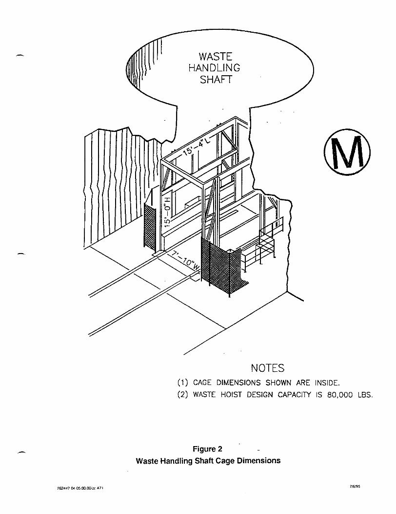
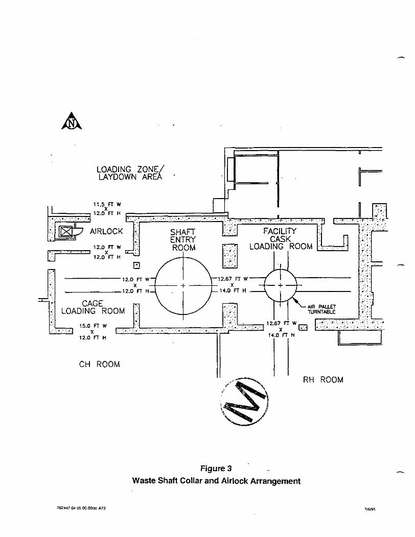
The Contractor is cautioned to be aware of the physical dimensions of the waste conveyance and the air lock (see Figures 2 and 3, attached).
The Contractor shall be responsible for any damage incurred by the existing site facilities as a result of his operations. Any damage shall be reported immediately to Westinghouse WID and repaired at the Contractor's cost.
3.4 Demobilization of Equipment and Facilities At completion of this work, the Contractor shall demobilize his equipment and facilities from the job site. The batch plant shall be disassembled and removed along with any unused material. All Contractor's equipment and materials shall be removed from the mine and all disturbed areas restored. Utilities shall be removed to their connection points unless otherwise directed by Westinghouse WID.
/ NOTES
(1) CAGE DIMENSIONS SHOWN ARE INSIDE.
(2) WASTE HOIST DESIGN CAPACITY IS 80,000 LBS.
Figure 2 .
Waste Handling Shaft Cage Dimensions
u
LOADING ZONE LAYDOWN AR E d . . .
CH ROOM
RH ROOM
Figure 3 .
Waste Shaft Collar and Airlock Arrangement
- 3.5 Site Cleanup At conclusion of the work, the Contractor shall remove all trash, waste, debris, excess construction materials, and restore the affected areas to its prior condition, to the satisfaction of Westinghouse WID. A final inspection of the areas will be conducted by Westinghouse WID and the Contractor before final payment is approved.
End of section.
SECTION 02222 EXCAVATION
SECTION 02222
EXCAVATION
PART 1 - GENERAL
1.1 Scope This section includes:
Excavation for main concrete barrier Excavation for surface preparation and levelling of base areas for isolation walls Disposition of excavated materials.
1.2 Related Sections
01010 - Summary of Work 01600 - Material and Equipment 03100 - Concrete Form Work 04300 - Unit Masonry System.
1.3 Reference Documents "Reference Stratigraphy and Rock Properties for the Waste Isolation Pilot Plant (WIPP) hoject" by R.D. Krieg-Sandia National Laboratory Document Sand 83-1908. [Available through National Technical Information Service (NTLS).]
1.4 Field Measurements and Survey All survey required for performance of the work will be provided by Westinghouse WID. To develop the concrete formwork to fit the excavation, the Conmctor shall be responsible for verifying the excavation dimensions.
PART 2 - PRODUCTS
Not used.
PART 3 - EXECUTION
3.1 Excavating for Concrete Barrier Excavation for the main concrete banier shall be performed to the lines and grades shown on the drawings. Excavate the back a minimum of 1 inch to 3 inches beyond clay seam G , and the floor a minimum of 1 inch to 3 inches below the anhydride marker bed 139 (MB-139) to
-.
PTlll-17-95 (12:40)1WPfl62447:02222spc 02222- 1
assure removal of the disturbed rock zone (DRZ). Excavation shall be performed utilizing - mechanical means such as a cutting head on a suitable boom, by drilling boreholes and using an expansive agent to fragment the rock or other competent equipment or methods submitted to Westinghouse WID for review and approval. The use of explosives is prohibited. The existing WIPP roadheader mining machine may also be available for use. The Contractor is to determine availability and coordinate proposed use of the roadheader with Westinghouse WID. The existing roadheader is capable of excavating the back and the portions of the ribs above the floor level. However, it is not capable of excavating the portion below floor level.
The tolerances for the concrete barrier excavation shall be +6 inches, to 0 inch. In addition, the Contractor is to remove all loose or spalling rock from the excavation surface to provide a sound surface abutting the concrete barrier. The Contractor shall provide and install roof bolts for support as required for personnel protection and approved ground control plans.
3.2 Excavating for Surface Preparation and leveling of Base Areas for Isolation Walls The Contractor shall excavate a 6-inch surface preparation around the entire perimeter of the isolation walls. The surface preparation in the floor shall be made level to produce a surface for placing the first course of block in the isolation walls. Tolerances for the leveled portion of the surface preparation are f 1 inch. Excavation may be performed by either mechanical or manual means. Use of explosives is prohibited.
3.3 Disposition of Excavated Materials The Contractor shall remove all excavated materials from the panel-access drift where they are excavated. Excavated materials shall be removed from the mine via the salt skip to the surface, where they will be disposed on site at a location as directed by Westinghouse WID.
3.4 Field Measurements and Survey All survey required for performance of the work will be provided by Westinghouse WID. The Contractor shall protect all survey control points, bench marks, ex., from damage by his operations. WID will verify by survey that the Contractor has excavated to the required lines and grades. The Contractor shall be responsible for verifying the excavation dimensions to develop concrete formwork to fit the excavation. No form work or block work is to be erected until this survey is completed. The Contractor is to coordinate the survey work with his operations to assure against lost time. The Contractor shall notify Westinghouse WID at least 24 hours prior to the time surveying is required
End of section.
SECTION 02722 GROUTING
SECTION 02722
GROUTING
PART 1 - GENERAL
1.1 Scope This section includes:
Grouting of concrete barrier.
1.2 Related Sections
01010-SummaryofWork 01400 - Contractor Quality Control 01600 - Material and Equipment 03100 - Concrete Form Work 03300 - Cast-in-Place Concrete
1.3 References - ASTM C1107-91a Standard Specification for Dry, Hydraulic Cement Grout (Nonshrink)
ASTM Clog/ Test Method for Compressive Strength of Hydraulic Cement Mortars C109M-95
1.4 Submittals for Review and Approval
Thirty days prior to the initiation of grouting, the Contractor shall submit to Westinghouse WID for review and approval, the following:
Type of grout proposed
hoduct data:
- Manufacturer's specification and certified laboratory tests for the manufactured grout, if proposed
- Certified laboratory tests for the salt-saturated grout, if proposed, using project-specific materials
Proposed grouting method, including equipment and materials and construction sequence in Work Plan.
1.5 Submittals for Construction Daily grouting report indicating the day, date, time of mixing and delivery, quantity of grout placed, water used, pressure required, problems encountered, action taken, quality control data, testing results, etc., no later than 24 hours following construction.
PART 2 - PRODUCTS
2.1 Grout Materials
Grout used for grouting in connection with fresh waterlplain cement concrete shall be nonshrink, cement-based grout, Five Star 110 as manufactured by Five Star Products Inc., 425 Stillson Road, F ~ ~ e l d , Connecticut 06430 or approved equal. Mixing and installation shall be in accordance with the manufacturer's recommendations.
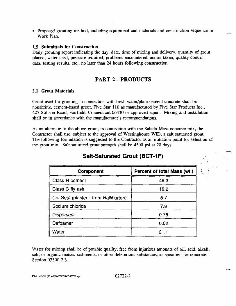
As an alternate to the above grout, in connection with the Salado Mass concrete mix, the Contractor shall use, subject to the approval of Westinghouse WID, a salt saturated grout. The following fonnulation is suggested to the Contractor as an initiation point for selection of the grout mix. Salt saturated grout strength shall be 4500 psi at 28 days.
Salt-Saturated Grout (BCT-1 F)
Component I Percent of total Mass (wt.)
I Class H cement 48.3
11 Class C fly ash I 16.2
1) Dispersant 1 0.78
Gal Seal (plaster - from Halliburton)
Sodium chloride
5.7
7.9
Water for mixing shall be of potable quality, free from injurious amounts of oil, acid, alkali, salt, or organic matter, sediments, or other deleterious substances, as specified for concrete, Section 03300-2.3.
Defoamer
Water
0.02
21.1
2.2 Product Data If the Contractor proposes to utilize a manufactured nonshrink cement-based grout, he shall submit complete manufacturer's specifications for the product, along with certified laboratory test results of the material.
If the Contractor proposes to utilize the salt-saturated grout in connection with the Salado Mass concrete mix, he shall submit manufacturer's/supplier's specifications for the component materials, and certified laboratory test results for the resultant mix.
PART 3 - EXECUTION
3.1 General The Contractor shall furnish all labor material, equipment, and tools to perform all operations in connection with the grouting.
Grout delivery and return lines for interface grouting shall be installed in the form work or in the area to be grouted to provide uniform distribution of the grout as shown on the drawings. The exact location of the boxes and lines shall be determined in the field. Additional grout delivery and return lines and boxes may be required by Westinghouse WID.
Pumps shall be positive displacement piston type pump designed for grouting service capable - of operating at a discharge pressure of 100 psi. The Contractor shall supply a standby pump to be utilized in the event of a breakdown of the primary unit
Mixers shall be high velocity "colloidal" type with a rotary speed of 1,200 to 1,500 rpm. Grout shall be mixed to a pumpable mix as per the manufacturer's recommendations.
Mixing water shall be accurately metered to control the~consistency of the grout.
The Contractor shall provide all necessary valves, gages, and pressure hoses.
Water for mixing is available at the waste shaft The Contractor is cautioned that no free water discharges or spills are Permitted in the mine. All cleanup and washout operations shall be performed at the ground surface.
Potential spill areas in the underground shall be identified by the Contractor in the work plan. The Contractor shall provide measures to contain suitable containment. Isolation measures shall include, but are not limited to, lining with a membrane material (PVC, hypalon, HDPE), draped curtains (polyethylene,PVC, etc.), corrugated sheet metal protective walls or a combination of these and other measures.
If salt-saturated grout is selected for use, the Contractor shall make provisions to accurately propomon the components. Proportioning shall be by weighing. Sufficient quantities of dry
A
components shall be developed prior to initiation of the grouting to perform the work so as A
not to incur delays during the rnixing/placing sequence.
3.2 Interface Grouting of Concrete Barrier After each cell of the concrete barrier has been allowed to cure for a period of seven days, or as directed by Westinghouse WID, the Contractor shall interface grout the remaining space between the back wall and the top surface of the concrete barrier.
Each cell of the concrete barrier shall be grouted before the next adjacent cell is formed and concrete placed. Grout delivery and return lines shall be installed with the form work as shown and called for on the drawings, or as directed by Westinghouse WID.
The placing of grout, unless otherwise directed by Westinghouse WID shall be continuous until completed. Grouting shall progress from lower to higher grout pipes. Grouting shall proceed through a single delivery line until grout escapes from the adjacent return line. The Conaactor shall then secure these lines and move to the next adjacent set of delivery and return lines. Pressure shall be adjusted to adequately deliver the grout to the forms, as witnessed by grout in the return line.
The grouting operation shall be conducted in a manner such that it does not affect the k stability of the concrete barrier shucture.
3.3 Contact Grouting After completion of interface grouting if directed by Westinghouse WID, the Contractor shall contact grout to fill any remaining voids at the concrete barrierback wall interface. Contact grouting includes all operations to drill, clean, and grout holes installed in the concrete barrier.
The Contractor shall drill and grout the interface zone to the main concrete banier as directed by Westinghouse WID.
The location, direction, and depth of each grout hole shall be as directed by Westinghouse WID. The order in which the holes are drilled and the manner in which each hole is drilled and grouted, the proportions of the water used in the grout, the time of grouting, the pressures used in grouting, and all other details of the grouting operations shall be as directed by Westinghouse WID.
Wherever required, contact grouting will entail drilling the hole to a limited depth, installing a packer, and performing grouting.
3.3.1 Drilling The holes shall be drilled with rotary-type drills. Drilling grout holes with percussion-type drills will not be permitted except as approved by Westinghouse WID.
- The requirements as to location, depth, spacing, and direction of the holes shall be as directed by Westinghouse WID.
The minimum diameter shall be approximately 1112 inches.
When the drilling of each hole or stage of has been completed, compressed air will be used to flush out drill cuttings. The hole shall then be temporarily capped or otherwise suitably protected to prevent the hole from becoming clogged or obstructed until it is grouted.
3.3.2 Materials for Contact Grouting Standard weight black steel pipe conforming to ASTM A-53 shall be set in the concrete in the locations as directed by Westinghouse WID. All pipe and fittings shall be furnished by the Contractor.
The size of the grout pipe for each hole and the depth of the holes for setting pipe for grouting shall be as directed by Westinghouse WID. Care shall be taken to avoid clogging or obstructing the pipes before being grouted, and any pipe that becomes clogged or obstructed from any cause shall be cleaned satisfactorily or replaced.
The packers shall be furnished by the Contractor and shall consist of expansible tubes or rings of rubber, leather, or other suitable material attached to the end of the grout supply pipe. The packers shall be designed so that they can be expanded to seal the drill hole at the specified - locations and when expanded shall be capable of withstanding without leakage, for a period of 5 minutes, air pressure equal to the maximum grout pressures to be used.
3.3.3 Grouting Procedures Different grouting pressures will be required for grouting different sections of the grout holes. Pressures as high as necessary to deliver the grout but which, as determined by mal, are safe against concrete displacement shall be used in the grouting.
If, during the grouting of any hole, grout is found to flow from adjacent grout holes or con- nections in sufficient quantity to interfere seriously with the grouting operation or to cause appreciable loss of grout, such grout holes and connections shall be capped temporarily. Where such capping is not essential, holes shall be left open to facilitate the escape of air as the grout is forced into other holes. Before the grout has set, the grout pump shall be connected to adjacent capped holes and to other holes from which grout flow was observed, and grouting of all holes shall be completed. If during the grouting of any hole, grout is found to flow from points in the barrier, any parts of the concrete structure, or other locations, such flows or leaks shall be plugged or caulked by the Contractor as directed by Westinghouse WID.
As a safeguard against concrete displacement, excessive grout travel, or while grout leaks are being caulked, Westinghouse WID may require the reduction of the pumping pressure, intermittent pumping, or the discontinuance of pumping. - .. ..: -
The consistency of the grout mix shall be varied, as directed by Westinghouse WID, - depending on the conditions encountered. Where the grout hole or connection continues to take a large amount of grout after the mix has been thickened, Westinghouse WID may require that pumping be done intermittently, waiting up to 8 hours between pumping periods to allow grout in the barrier to set. After the grouting is complete, the pressure shall be maintained by means of stopcocks, or other suitable valve that it will be retained in the holes or connections being grouted.
3.4 Cleanup No clean-up or washing of equipment with water is allowed in the underground. No free water spills are permitted. All clean out or wash out requiring water will be performed above ground at the location approved by Westinghouse WID. See note above regarding potential spill areas in Section 3.1 - General.
3.5 Quality Control The Contractor shall provide a third-party quality control inspector at the site throughout the grout placement operations. The inspector shall determine that the grout mix is properly proportioned and properly mixed to the approved consistency. The inspector shall sample and make one set of grout cubes for compression testing for every 50 cubic feet of grout placed, or &action thereof, for each day of grout placement.
End of section.
SECTION 031 00 CONCRETE FORMWORK
SECTION 03100
CONCRETE FORMWORK
PART 1 - GENERAL
1.1 Scope This section includes:
Formwork for cast-in-place concrete with shoring, bracing, and anchorage Accessory items, grout pipes, concrete delivery pipes.
1.2 Related Sections
. 01010 - Summary of Work 01400 - Conaactor Quality Control . 01600 - Material and Equipment 02722 - Grouting 03300 - Cast-in-Place Concrete 04300 - Unit Masonry System
- 1.3 References
ACI 301-89 Specifications for Structural Concrete for Buildings
ACI 318-89(92) Building Code Requirements for Reinforced Concrete
ACI 347-94 Recommended Practice for Concrete Formwork
ASTM A-361 Standard Specification for Structural Steel A36M-91
ASTM A-53-90b Standard Specification for Pipe, Steel, Black, and Hot-Dipped Zinc Coated Welded and Seamless
ASTM A-325-91c Standard Specification for Structural Bolts, Steel, Heat-Treated 1201105 ksi Minimum Tensile Strength
ASTM A-615-95b Standard Specifications for Deformed and Plain Billet-Steel Bars for Concrete Reinforcement
AWS A3.0-94 Welding Terms and Definitions
AWS A5.1-91 Specification for Mild Steel Covered Arc Welding Electrodes
AWS Dl.1-94 Structural Welding Code-Steel
AISC Manual of Steel Construction Latest Edition
1.4 Submittais The Contractor shall submit the following supporting documentation for the adequacy of the formwork 30 days prior to initiation of work at site:
Shop detail drawings with appropriate calculations to support the adequacy of the formwork.
\ .i
" Mill test certification of materials utilized in construction of the forms. , .. 4 ',
, ,dL.' , : i +, ) i b \ . : '
Details of installation contained in the Contractor's Work Plan. .'! , ?f ~ $ >
b
1.5 Quality Assurance The design and detail of the formwork shall be conducted under direct supervision of a professional structural Engineer experienced in design of this work. Responsibilities include:
Fabricating formwork in accordance with AISC manual of steel construction.
Performing all welding in accordance with AWS D1.l smctural welding code.
Performing all bolting in accordance with AISC specification for structural joints using ASTM A325 or A490 bolts.
Performing work in accordance with ACI 301, 318, and 347, AISC and AWS standards. Maintain one copy of all standards at site.
PART 2 - PRODUCTS
2.1 Form Materials - Forms for the concrete barrier shall be constructed of ASTM A-36 steel.
Pipe inserts shall be ASTM A-53 black standard weight pipe.
Form spacers shall be ASTM A-36 round stock.
Bolts shall be ASTM A325 high strength structural bolts.
- Grout pipes shall be ASTM A-53 standard weight pipe or flex conduit as shown on the drawings.
Rock anchors shall develop strength equal to or greater than ASTM A-36 round stock.
Welding electrodes shall conform to AWS A5.1.
PART 3 - EXECUTION
3.1 General The Contractor shall furnish all labor material equipment and tools to perform all operations in connection with the design, detail, fabrication and erection of the formwork and the fabri- cation and installation of grout pipes for the main concrete barrier. All work shall be performed according to standards referred to in Paragraph 1.3.
The Contractor may, at his option submit an alternate design or modify the design shown on the drawings, subject to the approval of Westinghouse WID. All designs must be supported by design calculations stamped and sealed by a registered professional engineer.
The Contractor shall furnish, fabricate and install all grout pipes and grout boxes for both the .- concrete barrier and the isolation walls.
3.2 Shop Drawings The Consactor shall design and detail all formwork for the concrete barrier, complete with any required bracing and shoring for the concrete barrier as shown on the drawings, in accordance with ACI 318 and 347 and the AISC manual of steel construction.
The details shall incorporate provision for adjusting and modifying the formwork to suit the excavation. Excavation tolerances are given in Section 02222 Excavation.
The ConWactor shall be responsible for verifying the excavation dimensions to develop the concrete formwork to fit the excavation.
Prior to fabrication, the Contractor shall submit shop drawings complete with supporting calculations for reviewlapproval by Westinghouse WID 30 days prior to initiating work. The contractor shall incorporate all Westinghouse WID'S comments, revisions, resolve all questions and resubmit drawings for final approval prior to proceeding with fabrication.
3.3 Fabrication The Contractor shall fabricate all formwork and ancillary items in accordance with the latest edition of the AISC Manual of Steel Construction and the approved detail drawings.
Formwork shall contain all inserts for grouting and pumping concrete. Sufficient valving shall be provided on inserts to allow shut off of concrete and grout to prevent back flow through the form work.
All welding shall be in accordance with AWS D1.l structural welding code including operator and procedure certifications. Elements shall be welded using E-7018 low hydrogen electrodes. Panels shall be piece marked to correspond to the erection drawing@) and sequence at fabrication.
3.4 Installation , I
3.4.1 Grout Pipes The Contractor shall furnish, fabricate, and install all grout pipes and boxes as approved by Westinghouse WID. Grout pipes and boxes shall be attached to the back surface using masonry anchors as shown on the drawings or other approved methods. Grout pipes shall be connected to the inserts installed in the permanent forms and securely fastened to the formwork. All grout pipes will be blown out with compressed air after installation and prior to closure of the formwork to assure they are clean and free from debris or obstructions. Grout pipes shall then be temporarily capped to prevent entry of foreign matter until ready f o ~ grouting. The ConWactor shall apply masking tape to the grout box openings to prevent concrete infiltration during concrete placement.
3.4.2 Formwork - The steel formwork for the concrete barrier is to remain in place at completion of each segment of the barrier, therefore all formwork shall be free from oil, grease, rust, dirt, mud or other material that would prevent bonding by the concrete. Forms wiU not be oiled or receive application of release agent
The Contractor shall install formwork at the locations shown on the drawings to the lines and grades shown. Forms are to be mortar tight. The Contractor shall adjust the formwork to suit the contour of the excavation. Rock may be trimmed or chipped to suit where interferences are encountered. Where overexcavation has occurred in excess of the designed- in adjustability of the formwork, modifications shall be proposed to Westinghouse WID for his approval prior to installation. Installation of the formwork shall be reviewed and approved by Westinghouse WID prior to proceeding with concrete installation.
The Contractor shall provide a sealant or gasket material subject to the approval of Westinghouse WID.
3.5 Quality Control The Contractor shall arrange for and contract with an approved thiid party inspector to provide inspectio~z/testing services for the fabrication and installation of the formwork and ancillary items, as required by the QNQC plan.
- The Contractor shall furnish cert3ed mill test reports for all materials utilized in the fabrication.
All welding shall be in accordance with AWS D1.l structural welding code. The Contractor shall furnish welding operator and procedure ~ e r ~ c a t i o n s for all operators and procedures utilized.
Fabricated components shall be inspected for dimension and overall quality. Welds shall be inspected by an AWS certified welding inspector.
The inspector shall visually inspect the installation for fit-up and dimensionally for location.
3.6 Handling, Shipping, Storage The Contractor shall handle, ship, and store fabricated components with care to avoid damage. Stored components shall be placed on timbers or pallets off the ground to keep the units clean. Components shall be tarped while in outdoor storage. Components that become spattered or contaminated with mud will be thoroughly cleaned during erection, and prior to concrete emplacement. Damaged components will be rejected by the inspector and replaced by the contractor at his cost.
End of section.
SECTION 03300 CAST-IN-PLACE CONCRETE
SECTION 03300
C AST-IN-PLACE CONCRETE
PART 1 - GENERAL
1.1 Scope This section includes:
Cast-in-place concrete for concrete barrier Concrete mix design.
1.2 Related Sections
01010 - Summary of Work 01400 - Contractor Quality Control 01600 - Material and Equipment 02222 - Excavation 02722 - Grouting
A 03 100 - Concrete Formwork
1.3 References
ACI 211.1-91 Standard Practice for Selecting Proportions for Normal, Heavy Weight, and Mass Concrete
ACI 318.1-89(92) Buildiig Code Requirements for Structural Plain Concrete
ACI 304R-89 Guide for Measuring, Mixing, Transporting, and Placing Concrete
ASTM C 33-93 Standard Specification for Concrete Aggregates
ASTM C 39-94 Standard Test Method for Compressive Strength of Cylindrical Concrete Specimens
ASTM C 94-94 Standard Specification for Ready-Mixed Concrete
ASTM C 136-95a Standard Test Method for Sieve Analysis of Fine and Coarse Aggregates
ASTM C 143-90a Standard Specification for Slump of Hydraulic Cement Concrete
fTlI1-17-95 (13:OS)Wr76~7:03MO.spc 03300-1
ASTM C 150-95 Standard Specification for Portland Cement
ASTM C 186-94 Standard Test Method for Heat of Hydration of Hydraulic Cement
ASTM C 4031 C 403M-95
ASTM C 494-95
ASTM C 618-94a
ASTM C 845-90
ASTM D 2216-92
USACE CRD-C 36
USACE CRD-C 48
API 10
NRMCA
Standard Test Method for Time of Sening of Concrete Mixtures by Penetration Resistance
Standard Specification for Chemical Admixtures for Concrete
Standard Specification for Coal Fly Ash and Raw or Calcined Natural Pozzolam for Use as an Admixutre in Portland Cement Concrete
Standard Specification for Expansivce Hydraulic Cement
Standard Test Method for Laboratory Determination of Water (moisture) Content of Soil and Rock
Method of Test for Thermal Diffusivity of Concrete
Standard Test Method for Water Permeability of Concrete
Cements
Check List for Certification of Ready Mixed Concrete Production Facilities
NRMCA Concrete Plant Standards
Westinghouse WID Standards
WIPP-DOE-7 1 ..
Design Criteria Waste Isolation Pilot Plant, Revised Mission Concept -- IIA (DOE, 1984)
WP 03-1 WIPP Startup and Acceptance Test Program (Westinghouse, 1993b)
WP 09-010 Design Development Testing (Westinghouse, 1991)
WP 09-CN3021 Component Numbering (Westinghouse, 1994a)
WP 09-024 Configuration Management Board~Engineering Change Proposal (ECP) (Westinghouse, 1994b)
- 1.4 Submittals for ReviewlApproval The Contractor shall submit the following for approval 30 days prior to initiating any work at the site:
Type of concrete proposed
Product Data - Laboratory test data and trial mix data for the proposed concrete to be utilized for the concrete barrier.
Proposed method of installation, including equipment and materials in work plan.
1.5 Submittals at Completion Laboratory test data developed during the installation of the concrete barrier.
1.6 Quality Assurance Perform work in accordance with the Contractor's Quality Control Plan and referenced ACI and ASTM standards.
Acquire cement, aggregate and component materials from the same source throughout the work.
- PART 2 - PRODUCTS
2.1 Cement Portland cement shall conform to ASTM C150 Type 11 modified with Pozzola .- plain cement concrete or API 10 Class H oil well cements. Cement utilized in the mix shall be Portland cement, Type II modified with pozzolan or type IV, to limit the heat of hydration of the resultant mix. The source of the cement to be used s h d be indicated and manufacturer's certif~cation that the cement complies to the applicable standard shall be provided with each shipment.
2.2 Aggregates Aggregates shall be quartz aggregates conforming to the requirements of ASTM C33.
Fine aggregate shall meet the requirements of ASTM C33 having a fineness modulus in the range of 2.80 to 3.00.
Coarse aggregate maximum size shall be 1 1R inches and shall be clean, cubical, angular, 100 percent crushed aggregate without flat or elongated particles.
The source of the aggregate is to be indicated and test reports certifying that the aggregate complies with the applicable standard are to be submitted for approval with the aid mix data.
2.3 Water Water used in mixing concrete shall be of potable quality, free of injurious amounts of oil, -.
acid, alkali, organic matter, or other deleterious substances.
Water shall conform to the provisions in ASTM C94, and in addition, shall conform to the following:
pH not less 6.0 or greater than 8.0
Carbonates andlor bicarbonates of sodium and potassium: 1000 ppm maximum
Chloride ions (CI): 250 ppm maximum
Sulfate ions (SO,): 1000 ppm maximum
Iron content: 0.3 ppm maximum
Total solids: 2000 ppm maximum
When ice is used in concrete mix, the water used for making ice shall meet all of the above requirements.
The source 'of water is to be indicated and certified copies of test data from an approved laboratory confirming that the water to be used meets the above requirements shall be submitted for approval with the trial mix data.
2.4 Admixtures Pozzolan shall conform to ASTM C618. Sampling and testing of pouolans shall conform to ASTM C311. Approximately 5 percent by weight of pozzolan may be used to replace cement in the mixes when approved.
All admixtures shall conform to ASTM C-494. The source of any admixtures proposed are to be indicated and certified copies of test data from an approved laboratory shall be submitted for approval with the trial mix.
2.5 Target Properties of the Concrete Mix The Contractor shall develop and proportion a plain cement concrete mix for use in constructing the concrete barrier. The Contractor shall demonstrate by trial mix that the proposed concrete meets the following properties:
- Target properties for Barrier Concrete
property Comment
4-hr working time ,Indicated by 8-inch slump (ASTM C 142) after 3-hr intermittent mixing. Max 10-inch slump at mixing.
Less than 25 "F heat rise prior to placement Difference between initial condition and temperature after 4 hr.
4,000 psi compressive strength (f,) At 28 days after casting (ASTM C 39)
Volume stability Length change between +0.05 percent and -0.02 percent (ASTM C 490)
Minimal entrained air 2 percent to 3 percent air
The Contractor shall use water reducing agents, plasticizers and other admixtures to achieve the slump and workability of the mix without adding excessive mixing water or excessive water-cement ratio. All admixtures shall conform to ASTM C-294.
The Contractor shall provide certified copies of test data from an approved laboratory demonstrating compliance with the above target properties.
C.
In addition to the target properties the Contractor shall provide certified test data for the trial mix for the following properties:
Heat of hydration ASTM C-186 Conc~ete Set ASTM C-403 Thermal Diffusivity USACE CRD-C36 Water Permeability USACE CRD-C43
2.6 Salado Mass Concrete The Contractor may elect to utilize the Salado Mass concrete in preference to developing a plain cement concrete. If Salado Mass concrete is selected, the Contractor shall demonstrate that the Salado Mass concrete meets the target properties shown above. Recommended initial proportioning of the Salado Mass concrete is as follows:
Component Percent of Total Mass
Class H cement (API 10)
Chem Comp 111 (ASTM C-845 Type K)
Class F fly ash (ASTM C-618)
Fine aggregate
Coarse aggregate
Sodium chloride
Defoaming agent
Sodium citrate
Water
The Contractor shall prepare a trial mix and provide certif~ed test data from an approved testing laboratory for slump, compressive strength, heat rise, heat of hydration, concrete set time, thermal diffusivity, and water permeability as indicated above for the plain concrete mix.
PART 3 - EXECUTION
3.1 General The Contractor shall provide all labor material, equipment and tools necessary to develop, supply, mix, transport and place mass concrete in the forms as shown on the drawings and called for in these specifications. All work shall be according to the standard references in paragraph 1.3.
The Conaactor will be required to provide and erect on the site a batch plant, suitable to store, handle, weight and deliver the proposed concrete mix. The batch plant shall be certified to NRMCA standards. The batch plant shall be erected on site in the location as directed by Westinghouse WID.
The Contractor shall batch, mix, and deliver to the underground, sufficient quantity of concrete to complete placement of concrete within one form section, as shown on the drawings. Once begun, placement of concrete in a section shall be continuous until completed. Target time for concreting one section is eight to ten hours allowing an additional two hours for clean up of equipment, for a total 10- to 12-hour shift.
- It is expected that addition of water to the dry materials and mixing of the concrete will occur at the ground surface with transport of wet concrete to a pump at the underground level where it will be pumped into the forms.
The Contractor is to provide all transport vehicles or means to transfer the wet concrete from the mixer truck to the pump. It is expected that the Contractor will use the waste conveyance hoist to transfer from the ground surface to the mine level. The Contractor is to familiarize himself with the dimensions of the waste conveyance and the airlock in order to provide suitable transport vehicles. The Contractor is also to familiarize himself with the capacity and speed of the conveyance to allow transfer of sufficient concrete to sustain the continuing placement of concrete. (See Figures 2 and 3 attached to Section 02010 - Mobilization and Demobilization).
The Contractor shall determine the horizontal distance to the entry where placement of the concrete barrier is to occur, and develop a route, with the approval of Westinghouse WID for traffic flow within the underground.
Details of the logistics for handling the concrete shall be included in the Contractors' Work Plan, and submitted to Westinghouse WID for approval prior to start of work at the site.
Potential spill areas in the underground shall be identified by the Contractor in the Work Plan. The Contractor shall provide measures to contain and isolate any water from contact - with the halite in these areas. Suitable containment isolation measures shall include but are not limited to, lining with a membrane material (PVC, hypalon, HDPE), draped curtains (polyethylene, PVC, etc.), corrugated sheet metal protective walls or a combination of these and other measures.
3.2 Pumping Concrete The Contractor shall provide pumping equipment suitable for placing the concrete into the forms. The Contractor at a minimum, shall provide an operating and a spare pump, to be used in the event of breakdown of the primary unit. After transporting and prior to pumping the concrete shall be remixed to compensate for segregation of aggregate during transport. The Contractor shall indicate the equipment proposed for pumping (manufacturer, model, type, capacity, pressure and remixing at the point of delivery in the Work Plan).
Each batch of concrete shall be checked at the surface at the time of mixing and again at the point of transfer to the pump for slump and temperature, and shall conform to the following:
Max. slump at mixing - 10 inches Max. slump at delivery to pump - 8 inches Max. temperature at placement = 70°F
Note: No water is to be added to the mix after the initial mixing and slump a
The Contractor shall connect to the pipe ports fabricated into the forms for delivery of the A
concrete, beginning with the lowest ports first Pumping shall continue until concrete is seen in the adjacent port at which time the delivery hose wiU be transferred to that port and the first port capped.
Pumping shall continue moving laterally then upward until the entire form is filled and the pour is completed.
3.4 Coordination of Work The Contractor is to coordinate his work mixing, transporting, and placing the mass concrete with the on-going operations in the underground. Coordination of use of the facilities and existing equipment shall be through Westinghouse WID.
3.5 Clean-Up No clean up or washing of equipment with water will be allowed in the underground. No free water spills are permitted in the underground. All clean-out or wash-out requiring water will be performed above ground at the location approved by Westinghouse WID.
3.6 Quality Control The Contractor shall provide a third-party quality control inspector at the site throughout the concrete placement. The inspector shall be responsible for determining that the batch plant is proportioning the mix according to the approved proportions. The batch plant shall provide a print out of batch quantities for each truck delivered to the mine. The inspector shall also determine the slump for each batch as it is mixed and allow additional water to be added until the initial slump is achieved. No additional water is to be added after this time. Temperature will also be recorded at this time.
The inspector shall also determine the slump and temperature following the remixing when concrete is transferred to the pump. Concrete not meeting or exceeding the specification is to be rejected and removed from the underground.
Concrete test cylinders to determine unconfined compression strength shall be taken by the inspection at the delivery from remixer to the pump in the underground. Four (4) cylinders shall be made for each 50 cubic yards of concrete placed. Cylinders shall be sealed with polyethylene and taped and field cured at ambient temperatures in the mine adjacent to the concrete barrier area. Two (2) samples shall be tested at 7 days and the remaining two (2) at 28 days.
End of section.
SECTION 041 00 MORTAR
SECTION 04100
MORTAR
PART 1 - GENERAL
1.1 Scope This section includes:
Mortar for Isolation Wall Construction.
1.2 Related Sections
01010 - Summary of Work 01400 - Contractor Quality Control 01600 - Material and Equipment 04300 - Unit Masonry System
1.3 References
ASTM C91-95
ASTM C144-93
ASTM C150-95
ASTM C207-91
ASTM C270-94
ASTM C780-94
ASTM C1142-94
ASTM E447-92
Standard Specification for Masonry Cement
Standard Specification for Aggregate for Masonry Mortar
Standard Specification for Portland Cement
Standard Specification for Hydrated Lime for Masonry Purposes
Standard Specification for Mortar for Unit Masonry
Standard Test Method for Preconstruction and Construction Evaluation of Mortars for Plain and Reinforced Unit Masonry
Ready-Mixed Mortar for Unit Masonry
Test Methods for Compressive Strength of Masonry Prisms
1.4 Submittals for Review The Contractor shall submit at the site.
Design mix. A
PTIII-17-95 (12:40)Wn62447:MlOO.spc
and Approval for approval the following 30 days prior to the initiation of work
Certified laboratory tests for the proposed design mix, indicating conformance of mortar to - property requirements of ASTM C270, and test and evaluation reports to ASTM C780.
1.5 Submittals a t Completion Certified laboratory test results for the construction testing of mortar mix.
1.6 Quality Assurance Perform work in accordance with the Contractor's Quality Control Plan and referenced ASTM standards. Acquire cement, aggregate, and component materials from the same source throughout the work.
1.7 Delivery Storage Handling Maintain packaged materials clean, dry and protected against dampness, freezing and foreign matter.
PART 2 - PRODUCTS
2.1 Mortar Mix The Contractor shall provide m o m for Isolation Walls, which shall be in conformance with ASTM C27O type M, using the property specification (3,000 psi at 28 days).
Sand for mortar shall conform to ASTM C144. - Water used for mixing mortar shall be of potable quality, free of injurious amounts of oil, acid alkali, organic matter, sediments, or other deleterious substances, as specified for Concrete, Section 03300 2.3.
The supply of materials as defined in the design mix shall remain the same throughout the iob.
The Contractor shall furnish all labor material equipment and tools to perform all operations in connection with supplying and mixing mortar for constructing the isolation walls.
The Contractor shall fully describe his proposed mortar mixing operation, including proposed equipment and materials in the Work Plan.
- 3.2 Mortar Mixing Mortar shall be machine-mixed with sufficient water to achieve satisfactory workability. Maintain sand uniformly damp immediately before the mixing process. If water is lost by evaporation, retemper only within one and one half hours of mixing. Use mortar within two hours of mixing at ambient temperature of 85" in the mine.
3.3 Installation The Contractor shall install mortar to the requirements of Section 04300 Unit Masonry System.
3.4 Field Quality Control The Contractor shall provide a third party Quality Control Inspector to perform all sampling and testing to c o n f i i that the mortar mix conforms to the proposed mix properties developed in the design mix.
Construction testing of mortar mix shall be in accordance with ASTM C780 for compression strength. Four (4) prism specimens shall be taken for each 50 cu. ft. of mortar or fraction thereof placed each day.
End of Section.
SECTION 04300 UNIT MASONRY SYSTEM
SECTION 04300
UNIT MASONRY SYSTEM
PART 1 - GENERAL
1.1 Scope This section includes:
Concrete Masonry Units
1.2 Related Sections
01010 SurnmaryofWork 01400 ConEactor Quality Control 01600 Material and Equipment 02722 Grouting
+ 03100 Concrete Formwork 04100 M o m
- 1.3 References
ASTM C55-94a Standard Specification for Concrete Building Brick
ASTM C140-94a Standard Method of Sampling and Testing Concrete Masonry Units
1.4 Submittals for Revision and Approval The Contractor shall submit for approval the following 30 days prior to initiation of the work at the site.
Certified laboratory test results for the proposed solid masonry units.
1.5 Quality Assurance Perform the work in accordance with the Contractor's Quality Control Plan.
PART 2 - PRODUCTS
2.1 Concrete Masonry Units Concrete masonry units shall be solid (no cavities or cores), load bearing high-strength units having a minimum compressive strength of 3500 psi. Concrete masonry units shall be tested
.-.
in accordance with ASTM C140. All other aspects of the concrete masonry units shall comply with ASTM C55, Type I Moisture Controlled.
Nominal modular size shall be 8 x 8 x 16 inches, or as otherwise approved by Westinghouse WID.
Concrete brick shall comply with ASTM C55, Grade N, Type I (moisture controlled) having a minimum compressive strength of 3500 psi (Avg. 3 units) or 3000 psi for individual unit.
2.2 Mortar Mortar shall be as specified in Section 04100 Mortar.
PART 3 - EXECUTION
3.1 General The Contractor shall furnish all labor, material, equipment and tools to perform all operations of installing Unit Masonry Isolation Walls to the lines and grades shown on the drawings.
The Contractor shall examine the excavation of the entry to affm that the keys have been properly leveled and cut to the appropriate depths, at the proper locations prior to any to any work.
3.2 Installation The Contractor shall install the isolation walls using concrete masonry units as specified above. Masonry units shall be installed with 318-inch mortar joints with full mortar bedding and full head joints. Masonry units shall be installed in running bond with headers every third course. Masonry units shall be mortared tight to the ribs and the back wall to provide a seal all around the isolation wall.
Concrete brick may be used as required for fit-up around grout pipes, or minimizing the dimensional fit-up at the top or sides of the isolation walls as approved by Westinghouse WID. The interface between the top of the isolation wall and the back wall shall be completely mortared to provide full contact between the back and the block wall.
3.3 Field Quality Control The Contractor shall provide a third-party Quality Control Inspector to inspect the installation of the Concrete Masonry Unit Isolation Walls. Inspection and testing of the mortar shall be in accordance with Section 04100 Mortar.