Embed Size (px)
DESCRIPTION
Use Cases Use case is a depiction of a system’s behavior or functionality under various conditions as the system responds to requests from users. Actor is an external entity that interacts with the system. Chapter 7 Appendix 3 © 2008 by Prentice Hall
Citation preview

AppendixObject-Oriented Analysis and Design: Use Cases and Sequence Diagrams
Modern Systems Analysisand Design
Fifth Edition
Jeffrey A. Hoffer Joey F. George
Joseph S. Valacich

© 2008 by Prentice Hall 2Chapter 7 Appendix
Learning Objectives
Explain use cases and use case diagrams and how they can be used to model system functionality.
Discuss process modeling with use cases for electronic commerce application.
Understand how to represent system logic with sequence diagrams.

Use Cases
Use case is a depiction of a system’s behavior or functionality under various conditions as the system responds to requests from users.
Actor is an external entity that interacts with the system.
Chapter 7 Appendix 3© 2008 by Prentice Hall

Use Cases (Cont.)
© 2008 by Prentice Hall 4Chapter 7 Appendix
Figure 7-23 A use case diagram for a university registration system.

Use Cases (Cont.)
Most actors represent user roles, but actors can also be external systems.
An actor is a role, not a specific user; one user may play many roles, and an actor may represent many users.
A use case model consists of actors and use cases.
Chapter 7 Appendix 5© 2008 by Prentice Hall

Use Cases diagrams
Use case diagram: a picture showing system behavior along with the key actors that interact with the system.
Abstract use case is when a use case is initiated by another use case.
A use case represents completely functionality.
© 2008 by Prentice Hall 6Chapter 7 Appendix

Definitions and Symbols
Use Case
Actor
Boundary
Connection
Include relationship
Extend relationship
<<include>>
<<extend>>
Chapter 7 Appendix 7© 2008 by Prentice Hall

Definitions and Symbols (Cont.)
Actor is a role, not an individual. Involved with the functioning of the system at
some basic level.Represented by stick figures.
Use case represents a single system function.Represented as an eclipse.
© 2008 by Prentice Hall 8Chapter 7 Appendix

Definitions and Symbols (Cont.) System boundary includes all the
relevant use cases.A boundary is the dividing line between the
system and its environment.Use cases are within the boundary.Actors are outside of the boundary.Represented as a box.
Chapter 7 Appendix 9© 2008 by Prentice Hall
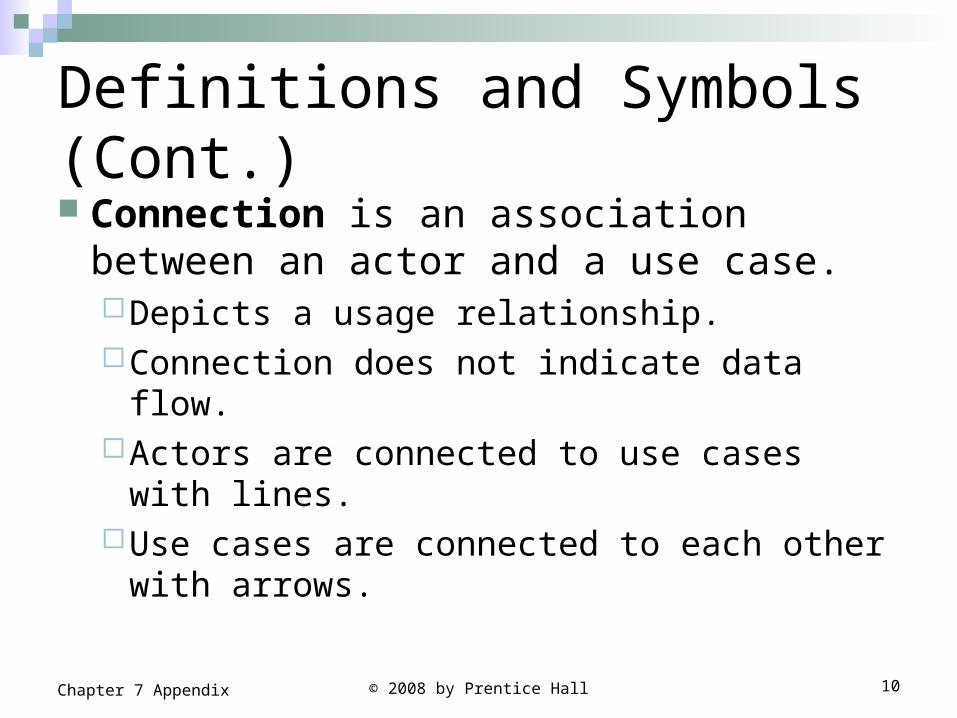
Definitions and Symbols (Cont.) Connection is an association between an
actor and a use case.Depicts a usage relationship.Connection does not indicate data flow.Actors are connected to use cases with lines.Use cases are connected to each other with
arrows.
Chapter 7 Appendix 10© 2008 by Prentice Hall

Definitions and Symbols (Cont.)
Extend relationship is an association between two use cases where one adds new behaviors or actions to the other.Extends a use case by adding new behavior
or actions.Specialized use case extends the general use
case.
Chapter 7 Appendix 11© 2008 by Prentice Hall

Definitions and Symbols (Cont.)
Include relationship is an association between two use cases where one use case uses the functionality contained in the other. Indicates a use case that is used (invoked) by
another use case.Links to general purpose functions, used by
many other use cases.
Chapter 7 Appendix 12© 2008 by Prentice Hall

Definitions and Symbols (Cont.)
© 2008 by Prentice Hall 13Chapter 7 Appendix
Figure 7-24 A use case diagram featuring an include relationship.
Written Use Cases
Document containing detailed specifications for a use case.
Contents can be written as simple text or in a specified format.
Step-by-step description of what must occur in a successful use case.
Chapter 7 Appendix 14© 2008 by Prentice Hall
Electronic Commerce Application: Process Modeling using Use Cases Model the functionality of Pine Valley
Furniture Webstore Application with a use case diagram.
Six high-level functions identified to be included in the use case diagram.
The functions represent the “work” or “action” parts of the Website.
© 2008 by Prentice Hall 15Chapter 7 Appendix
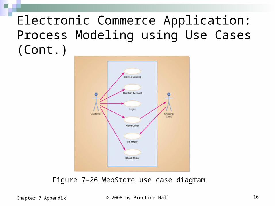
Electronic Commerce Application: Process Modeling using Use Cases (Cont.)
© 2008 by Prentice Hall 16Chapter 7 Appendix
Figure 7-26 WebStore use case diagram

Dynamic Modeling: Sequence Diagrams Sequence diagram: depicts the interactions
among objects during a certain periods of time. May be presented either in a generic form or in
an instance form. Generic form shows all possible sequences of
interactions – sequences corresponding to all the scenarios of a use case.
Instance form shows the sequence for only one scenario.

Dynamic Modeling: Sequence Diagrams (Cont.) Elements of a sequence diagram
Objects: represented by boxes at top of diagram.
Lifeline: the time during which an object exists.
Messages: means by which objects communicate with each other.

Dynamic Modeling: Sequence Diagrams (Cont.) Activation: the time period during which
an object performs an operation. Synchronous message: a type of
message in which the caller has to wait for the receiving object to finish executing the called operation before it can resume execution itself.

Dynamic Modeling: Sequence Diagrams (Cont.) Simple message: a message that transfer
control from the sender to the recipient without describing the details of the communication.
Asynchronous message: a message in which the sender does not have to wait for the recipient to handle the message.

Designing a Use Case with a Sequence Diagram
Figure 8-11 Sequence diagram for a class registration scenario without prerequisites

Summary In this appendix you learned how to: Explain use cases and use case
diagrams. Explain how they can be used to model
system functionality. Discuss process modeling with use cases
for electronic commerce application. Understand how to represent system
logic with sequence diagrams.
Chapter 7 Appendix 22© 2008 by Prentice Hall