Embed Size (px)
Citation preview
8/10/2019 Applicability of elastoplastic modelling for simulating tunnel excavation
http://slidepdf.com/reader/full/applicability-of-elastoplastic-modelling-for-simulating-tunnel-excavation 1/18
1
Abstract
This paper aims at examining the performance of the material models that arenormally adopted in finite-element analyses used to predict the ground deformationsassociated with tunnelling in lightly overconsolidated clay. The tunnel construction
problem is represented by a plane strain finite-element model under an undrainedcondition.Analyses are performed for a number of overconsolidation ratios representative tolightly overconsolidated clays. Solutions are obtained for ground volume loss
percentages that practically represent the ground loss associated with the closed faceshield tunnelling.The results of analyses show that the effectiveness of the constitiutive modeladopted in the analysis is dependent on the amount of plasticity that is expected todevelop.
Keywords: tunnelling, excavation, lightly overconsolidated clay, elastoplasticmodelling, undrained condition, finite-element analysis.
1 Introduction
It has become evident that prediction of the ground deformations caused byconstruction of buried and retaining structures is strongly dependent on theconstitutive relation used to model the soil behaviour. In order to obtain reliablenumerical results using the available constitutive models for soils, it is necessary toexamine the range of applicability of these models and consequently the limitationsinherited in them.
Paper 277
Applicability of Elastoplastic Modelling for SimulatingTunnel Excavation in Lightly Overconsolidated Clay
T.T. Abdel-Fattah†, A.M. Abdel-Rahman†, A.Y. Akl‡ and H.A. Hodhod‡† Department of Soil Mechanics and Foundation Engineering
Housing and Building Research Centre, Giza, Egypt‡ Department of Civil Engineering
Faculty of Engineering, Cairo University, Giza, Egypt
Civil-Comp Press, 2005.Proceedings of the Tenth International Conferenceon Civil, Structural and EnvironmentalEngineering Computing,
B.H.V. Topping (Editor),Civil-Comp Press, Stirling, Scotland.
8/10/2019 Applicability of elastoplastic modelling for simulating tunnel excavation
http://slidepdf.com/reader/full/applicability-of-elastoplastic-modelling-for-simulating-tunnel-excavation 2/18
2
Previous studies of modelling tunnel excavation using the finite-elementmethod predicted much shallower and wider surface settlement distributions thanthose predicted experimentally. These discrepancies were attributed to many reasonsas reported by a number of researchers (e.g., Lee and Rowe [1]; Gunn[2]; Simpsonet al . [3]; Addenbrooke et al . [4]; Burghignoli et al . [5]). Lee and Rowe [1] carriedout linear elastic perfectly plastic finite-element analyses of tunnelling specificallyto show the influence of the elastic cross anisotropy. They concluded that particularattention should be given to the ratio of independent shear modulus to verticalmodulus. However, Gunn [2] stated that the predictions of ground deformationsabove tunnels in London clay were not improved by the use of appropriateanisotropic elastic moduli. On the other hand, Simpson et al . [3] concluded that the
predicted surface settlement trough is substantially influenced by the anisotropicshear modulus, but little influenced by the non-linearity. Addenbrooke et al . [4]concluded that non-linear pre-failure deformation models are necessary to achievereasonable predictions for greenfield surface settlement profiles and mentioned thatincreasing the initial small strain stiffness in the linear elastic region does notimprove the settlement prediction at a desired volume loss. Burghignoli et al. [5]used a kinematic hardening model for natural clay with loss of structure proposed byRouainia and Wood [6] to predict the greenfield surface settlement profiles for atunnel constructed in cemented clay. They reported that despite the high nonlineardescription of the behaviour of the soil embedded in the model, only a slightimprovement in the prediction of the settlement trough was obtained.
It can be concluded from the previous discussion that there is no specificreasoning for such discrepancies. It is note worthy that most of the previous studies
were concerned with the behaviour of the highly overconsolidated clays orstructured clays.
The aim of this study is to examine the range of applicability of the constitutivemodels that are normally adopted in finite-element analyses used to predict theground deformations associated with tunnelling in lightly overconsolidated clay.Attention is drawn to the prediction of ground surface deformations.
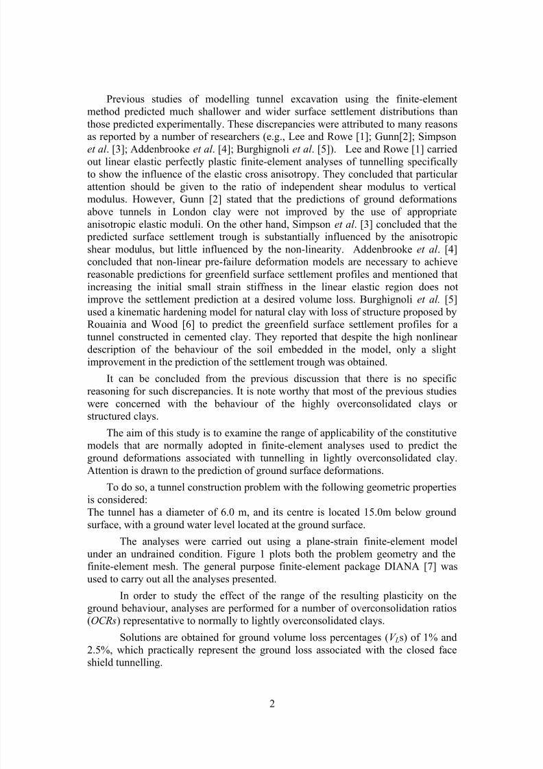
To do so, a tunnel construction problem with the following geometric propertiesis considered:The tunnel has a diameter of 6.0 m, and its centre is located 15.0m below groundsurface, with a ground water level located at the ground surface.
The analyses were carried out using a plane-strain finite-element modelunder an undrained condition. Figure 1 plots both the problem geometry and thefinite-element mesh. The general purpose finite-element package DIANA [7] wasused to carry out all the analyses presented.
In order to study the effect of the range of the resulting plasticity on theground behaviour, analyses are performed for a number of overconsolidation ratios(OCRs ) representative to normally to lightly overconsolidated clays.
Solutions are obtained for ground volume loss percentages ( V Ls) of 1% and2.5%, which practically represent the ground loss associated with the closed faceshield tunnelling.
8/10/2019 Applicability of elastoplastic modelling for simulating tunnel excavation
http://slidepdf.com/reader/full/applicability-of-elastoplastic-modelling-for-simulating-tunnel-excavation 3/18
3
Figure 1: Problem definition: Finite-element mesh and geometry
2 The constitutive models adoptedThe results of analyses were obtained using the following constitutive models inaddition to the linear elastic one:
- Mohr-Coulomb model and Druker-Prager model as representatives for thelinear elastic-plastic modelling,
- Delft-clay model (also know as Egg Cam-clay model) [8]&[9], and ModifiedMohr-Coulomb model [7] as representatives for the nonlinear elastic-hardening plastic modelling.
In order to examine the effect of material dilation on the results obtained here,solutions due to both associated plasticity and non-associated plasticity with non-
dialative behaviour are presented for both Mohr-Coulomb and Druker-Pragermodels.
2.1 Delft-clay model
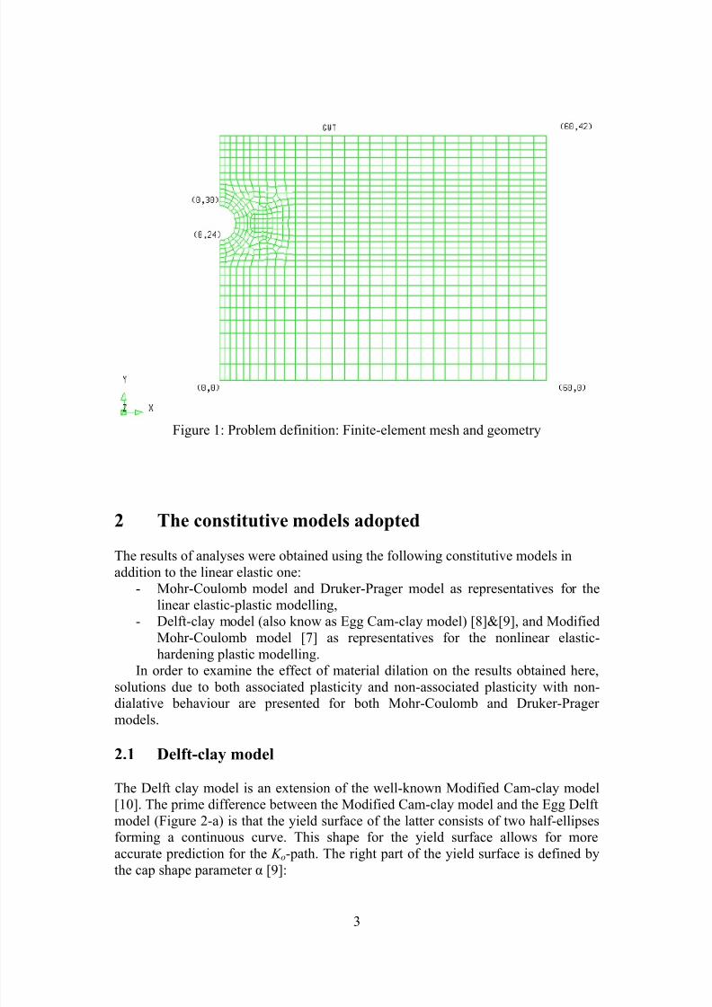
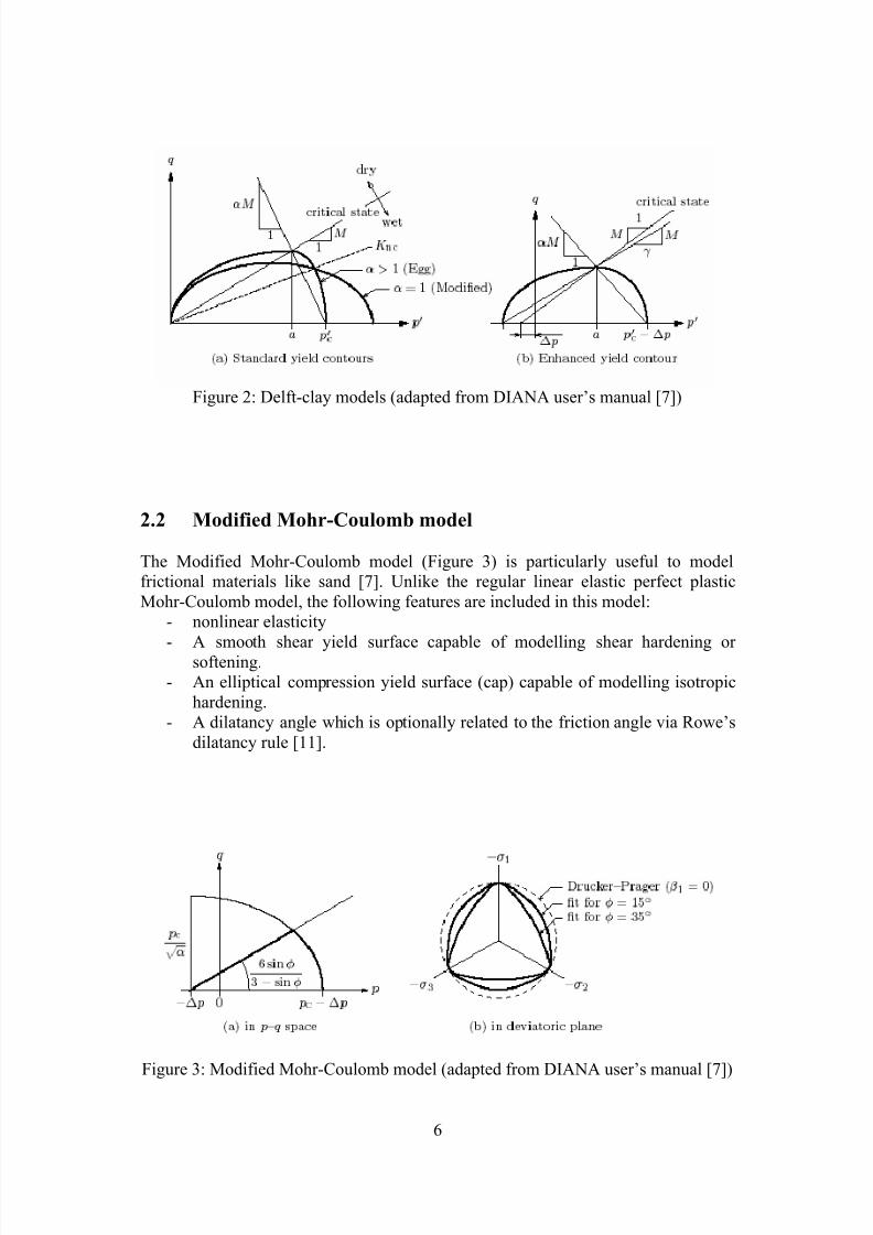
The Delft clay model is an extension of the well-known Modified Cam-clay model[10]. The prime difference between the Modified Cam-clay model and the Egg Delftmodel (Figure 2-a) is that the yield surface of the latter consists of two half-ellipsesforming a continuous curve. This shape for the yield surface allows for moreaccurate prediction for the K o-path. The right part of the yield surface is defined bythe cap shape parameter α [9]:
8/10/2019 Applicability of elastoplastic modelling for simulating tunnel excavation
http://slidepdf.com/reader/full/applicability-of-elastoplastic-modelling-for-simulating-tunnel-excavation 4/18
4
The yield surface is defined by:( )
0
1
1
1
2 2
2,
2
2,222 =′
+−−
′−′+
′−=ccegg p p p p M q f
α
α α
α
α α (1)
where
11 2,
=→′+
≤′ α α
α c P P (Modified Cam-clay) (2-a)
11 2,
>→′+
>′ α α
α c P P and .
21
1,2, cc p p ′+=′α
α (2-b)
inwhich p ′ = effective isotropic stressq = deviatoric stress
c p ′ = isotropic preconsolidation stress, and
φ φ
sin3sin6
−= M = slope of the critical state line. (3)
in which φ is the friction angle in traixial compression,
,2
4
2
x
xz y y −±−=α (4)
where
,1and ,12 ,22
2
−=
+−−==
M z
M T yT x ncnc η η
(5)
where
( )[ ],
6
1 121
22
Λ
−
−−
=a
M a
T
ncnc
η η
(6)
in which
φ φ
η sin23
sin3 −
=nc , and (7)
( )( )
( )ν
ν
213
11 −
Λ−+=a (8)
where
λ κ λ −=Λ (9)
whereλ = slope of the ICL as well as the CSL in the ln p'- υ plane,κ = slope of the SL in the ( υ -ln p' ) plane.A value of unity for α corresponds to the yield surface of the Modified Cam-claymodel, as can be seen from Figure 2.
It should be noted that the parameter α is estimated using the same material parameters used in the Modified Cam-clay model.
8/10/2019 Applicability of elastoplastic modelling for simulating tunnel excavation
http://slidepdf.com/reader/full/applicability-of-elastoplastic-modelling-for-simulating-tunnel-excavation 5/18
5
The nonlinear relation between the elastic volumetric strain and the isotropic pressure is defind via the tangential compression modulus K t obtained as:
pv
K t ′= κ (10)wherev = current specific volume.
For a constant Poissons ratio ν and under a condition of isotropy, the tangentshear modulus t G can be defined as:
ν ν
+−=
121
23
t t K G (11)
2.1.1 Enhanced Delft -clay model
In this model (Figure 2-b), the tangential bulk modulus during elastic swelling orreloading is expressed by:
( ),t t P P v
K +′=κ
(12)
in which t P = tensile pressure; a numerical artifice introduced to incorporate theeffect of the tensile stresses when the initial pressure is equal to zero; this effect isnot accounted for in the earlier models in which this expression reduces to Equation(10).
Incorporating the effect of the soil tensile strength into the expression for theyield surface of the Delft-clay yields:
( )( ) ( )( ) ,012 222
22 =−+−∆+′∆+′+= β
β aa P P P P
M q f (13)
where
P ∆ = reference pressure to model cohesion, and β = parameter calculated as:
γ β = , for a P P ≤∆+′ , and (14-a)
α β
1= , for a P P >∆+′ , (14-b)
whereγ = an optional shape factor for the dry side of the yield surface, anda = yield function parameter obtained from:
.1 α
α +
′=c P a (15)
8/10/2019 Applicability of elastoplastic modelling for simulating tunnel excavation
http://slidepdf.com/reader/full/applicability-of-elastoplastic-modelling-for-simulating-tunnel-excavation 6/18
6
Figure 2: Delft-clay models (adapted from DIANA user’s manual [7])
2.2 Modified Mohr-Coulomb model
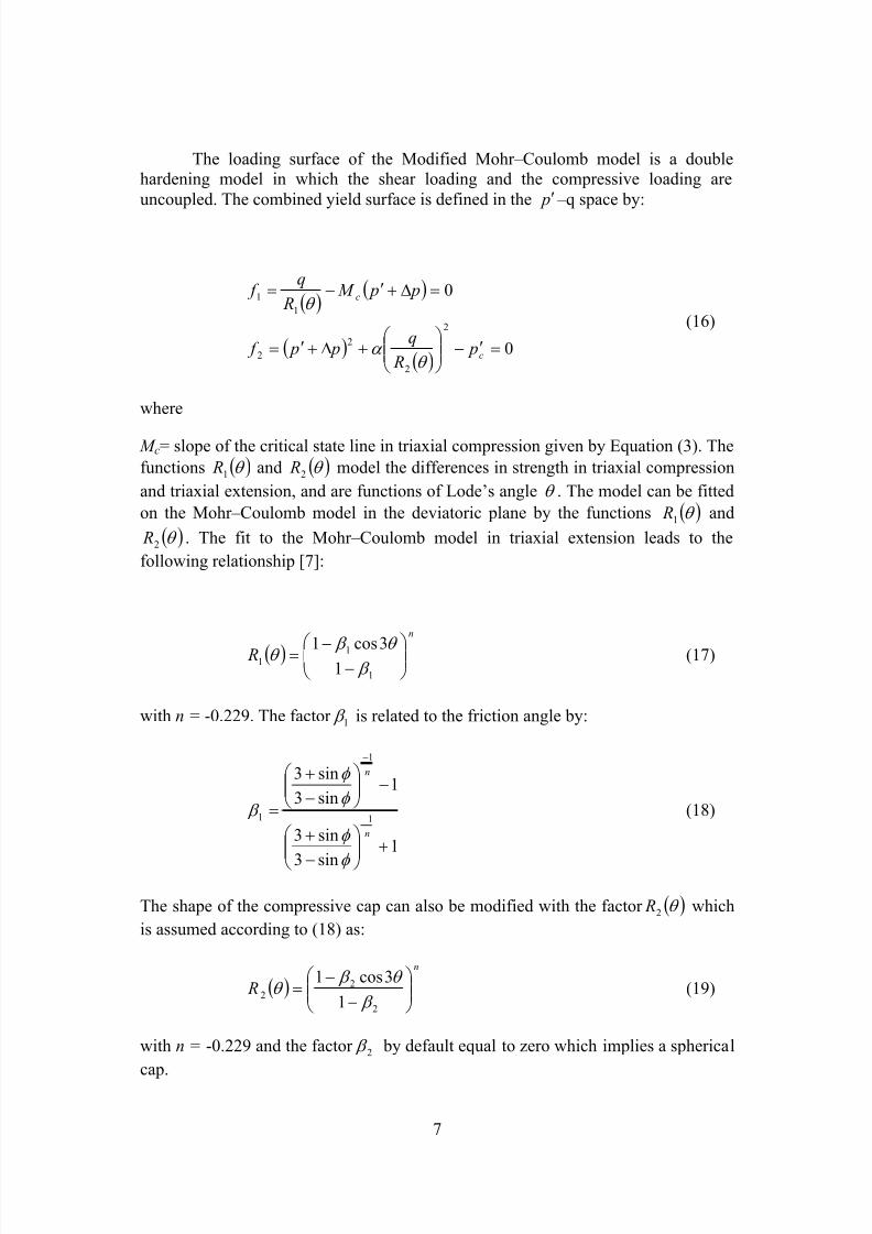
The Modified Mohr-Coulomb model (Figure 3) is particularly useful to modelfrictional materials like sand [7]. Unlike the regular linear elastic perfect plasticMohr-Coulomb model, the following features are included in this model:
- nonlinear elasticity
- A smooth shear yield surface capable of modelling shear hardening orsoftening.- An elliptical compression yield surface (cap) capable of modelling isotropic
hardening.- A dilatancy angle which is optionally related to the friction angle via Rowe’s
dilatancy rule [11].
Figure 3: Modified Mohr-Coulomb model (adapted from DIANA user’s manual [7])
8/10/2019 Applicability of elastoplastic modelling for simulating tunnel excavation
http://slidepdf.com/reader/full/applicability-of-elastoplastic-modelling-for-simulating-tunnel-excavation 7/18
7
The loading surface of the Modified Mohr–Coulomb model is a doublehardening model in which the shear loading and the compressive loading areuncoupled. The combined yield surface is defined in the p ′ –q space by:
( ) ( )
( )( )
0
0
2
2
22
11
=′−
+∆+′=
=∆+′−=
c
c
p R
q p p f
p p M R
q f
θ α
θ (16)
where
M c= slope of the critical state line in triaxial compression given by Equation (3). Thefunctions ( )θ 1 R and ( )θ 2 R model the differences in strength in triaxial compressionand triaxial extension, and are functions of Lode’s angle θ . The model can be fittedon the Mohr–Coulomb model in the deviatoric plane by the functions ( )θ 1 R and
( )θ 2 R . The fit to the Mohr–Coulomb model in triaxial extension leads to thefollowing relationship [7]:
( )n
R
−−=
1
11 1
3cos1 β
θ β θ (17)
with n = -0.229. The factor 1 β is related to the friction angle by:
1sin3
sin3
1sin3sin3
1
1
1
+
−
+
−
−+
=−
−
n
n
φ
φ
φ φ
β (18)
The shape of the compressive cap can also be modified with the factor ( )θ 2 R whichis assumed according to (18) as:
( )n
R
−
−=
2
22 1
3cos1 β
θ β θ (19)
with n = -0.229 and the factor 2 β by default equal to zero which implies a sphericalcap.
8/10/2019 Applicability of elastoplastic modelling for simulating tunnel excavation
http://slidepdf.com/reader/full/applicability-of-elastoplastic-modelling-for-simulating-tunnel-excavation 8/18
8
The nonlinear elastic behviour of the Modified Mohr-Coulomb model istaken identical as for the Enhanced Delft-clay model.
2.3 Clay material parameters
The material parameters used with both the Delft-clay model and the ModifiedMohr-Coulomb model are listed in Table 1.
The coefficient of lateral earth pressure is assumed to vary with theoverconsolidation ratio, OCR according to the following relation:
( )ν
ν −
−−=1
.1. OCR K OCR K nco (20)
Total unit weight (kN/m3) 16.53Cohesion (kPa) 1Friction angle (degree) 30Slope of isotropic unloading line 0.043Slope of isotropic compression line 0.2326Initial void ratio 1.5Poisson’s ratio 0.15Ko, lateral earth pressure coefficient Equation (20)
Over consolidation ratio 1,1.3, and 1.5Analysis type Effective/Undrained
Table 1: Clay parameters for Delft-clay model and Modified Mohr-Coulomb model
For the Mohr-Coulomb, Druker-Prager, and linear elastic models, theYoung’s modulus is obtained from the Delft-clay model parameters using therelation
( )κ
ν )21(3 −+′=′ t
p pv E , (21)
which provides a Young’s modulus varying with depth.Although the results obtained are due to OCR ratios of 1, 1.3, and 1.5, the
OCR ratio for the top 2.5m of soil is kept constant at a value of 1.5. Also, the valueassigned to the shear modulus for the top 2.5 m of soil is that value calculated at adepth of 2.5 m below the ground surface.
It is to be noted that the results due to Delft-clay model were obtained hereusing both the soil angle of internal friction φ , as well as a reduced angle of internalfriction r φ . The reason for using the latter is that the stress path around the tunnel
perimeter may be represented by triaxial extension for both the tunnel crown and
8/10/2019 Applicability of elastoplastic modelling for simulating tunnel excavation
http://slidepdf.com/reader/full/applicability-of-elastoplastic-modelling-for-simulating-tunnel-excavation 9/18
9
invert, and by active compression for the tunnel springline. Accordingly, the criticalstate parameter, denoted here by , may be better estimated from [12]:
=2
ext comp M M +, (22)
where
φ φ
sin3sin6
−=
comp M representing the state of triaxial compression,
and
φ φ
sin3sin6
+=
ext M representing the state of triaxial extension.
Then, the reduced angle of internal friction ϕ r is obtained from
M M
r +=
63sin φ (23)
Although the Modified Mohr-Coulomb model is basically used formodelling sand, it is used here for clayey soils using a predefined value for thecompression-yield surface shape-parameter α , as well as a restricted value of zerofor the dilatancy angle to represent the behaviour of clay at the critical state. The capshape parameter is estimated such that the compression yield surface approximatelycoincides with the wet-side of the Modified Cam-clay model or the Delft-clay one. Itis found that the values of this parameter that satisfying this condition are 2 and 0.90respectively.
Therefore, the prime difference between the Delft-clay model and theModified Mohr-Coulomb model lies in the difference between the shape of the yieldsurface in the deviatoric plane. The yield surface of the latter allows for bettermodelling since it takes into account the effect of the Lode’s angle.
3 Analysis of results
3.1 Analytical solutions
It is well known that the observed surface settlement profiles can be successfullydescribed by an inverted normal (Gaussian) curve defined as:
−=2
2
max 2exp
i x
S S y y (24)
8/10/2019 Applicability of elastoplastic modelling for simulating tunnel excavation
http://slidepdf.com/reader/full/applicability-of-elastoplastic-modelling-for-simulating-tunnel-excavation 10/18
10
whereS y = settlement at a given point,S ymax = maximum settlement at the tunnel centre-line,
x = horizontal distance from the tunnel centre-line, andi = horizontal distance from the tunnel centre-line to the point of inflection of thesettlement trough (the standard deviation).Equation (24) was validated by a number of researchers (e.g., Schmidt [13]; Peck[14]; O’Reilly and New [15]; Grant and Taylor [16]).
The total half-width of the settlement trough in practical situations normallyranges from 2.5 i to 3.0 i.
The volume of the surface settlement trough, Vs, per unit length of the tunnelcan be obtained by integrating Equation (24) with respect to x; this yields:
maxmax 50.22 y y s S iS V ≅= π (25)
The ground loss, V o, is the amount of ground lost in the region close to thetunnel due to the tunnelling process; it is equal to the volume (per unit length)enclosed between the theoretical and the deformed excavation surfaces. Fortunnelling in clays, V s is practically equal to V o, since the ground movements usuallyoccur under an undrained condition.
The field measurements obtained by O’Reilly and New [15] for the surfacesettlements in cohesive soils above a number of tunnels in the UK suggested that:
o KZ i = , (26)
where K = 0.5 for cohesive soils, and Z = depthof the tunnel axis.A further review of the field data obtained by O’Reilly and New [15] showed thatfor cohesive soils, K ranges from 0.4 (stiff clays) to 0.7 (soft clay, and silty clay). Through out the present study, values of K= 0.5 and 0.6 are considered for theanalytical solution.
O’Reilly and New [15] suggested that the horizontal ground surfacemovement under an undrained condition can be expressed by:
,o
y x
z
xS S = (27)
provided that the Gaussian distribution shape parameter, K is constant with depth.Grant and Taylor [16] introduced the following enhanced relation for
predicting the horizontal ground movement at depth z in clays taking into accountthe variation of K with depth:
( ) z Z
yS S
o
y x
−
+
=
325.0175.0
1
, (28)
8/10/2019 Applicability of elastoplastic modelling for simulating tunnel excavation
http://slidepdf.com/reader/full/applicability-of-elastoplastic-modelling-for-simulating-tunnel-excavation 11/18
11
3.2 Results of finite-element analyses
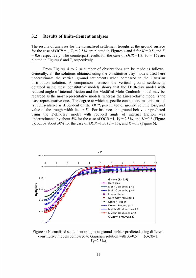
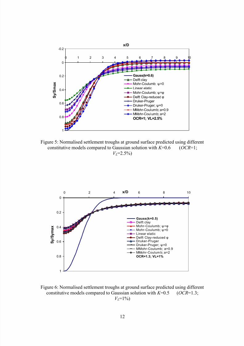
The results of analyses for the normalised settlement troughs at the ground surfacefor the case of OCR =1, V L = 2.5% are plotted in Figures 4 and 5 for K = 0.5, and K = 0.6 respectively. The counterpart results for the case of OCR =1.3, V L = 1% are
plotted in Figures 6 and 7, respectively.
From Figures 4 to 7, a number of observations can be made as follows:Generally, all the solutions obtained using the constitutive clay models used hereunderestimate the vertical ground settlements when compared to the Gaussiandistribution solution. A comparison between the vertical ground settlementsobtained using these constitutive models shows that the Delft-clay model withreduced angle of internal friction and the Modified Mohr-Coulomb model may be
regarded as the most representative models, whereas the Linear-elastic model is theleast representative one. The degree to which a specific constitutive material modelis representative is dependent on the OCR, percentage of ground volume loss, andvalue of the trough width factor K . For instance, the ground behaviour predictedusing the Delft-clay model with reduced angle of internal friction wasunderestimated by about 5% for the case of OCR =1, V L = 2.5%, and K =0.6 (Figure5), but by about 50% for the case of OCR =1.3, V L = 1%, and K =0.5 (Figure 6).
-0.2
0
0 .2
0 .4
0 .6
0 .8
1
0 1 2 3 4 5 6 7 8 9 1 0
x/D
S y / S y m a x
Gauss (k=0 .5 )Delft clay
Mohr-Coulumb; ψ = φ
Mohr-Coulumb; ψ = 0
Linear elaticDelft Clay-reduced φ
Druker-Pruger Druker-Pruger; ψ = 0
MMohr-Coulumb; a=0.9
MMohr-Coulumb; a=2
OCR=1; VL=2.5%
Figure 4: Normalised settlement troughs at ground surface predicted using differentconstitutive models compared to Gaussian solution with K =0.5 ( OCR =1;
V L=2.5%)
8/10/2019 Applicability of elastoplastic modelling for simulating tunnel excavation
http://slidepdf.com/reader/full/applicability-of-elastoplastic-modelling-for-simulating-tunnel-excavation 12/18
12
-0.2
0
0.2
0.4
0.6
0.8
1
0 1 2 3 4 5 6 7 8 9 10
x/D
S y / S m a x
Gauss(k=0.6)Delft clayMohr-Coulumb; ψ =0Linear elaticMohr-Coulumb; ψ =φ
Delft Clay-reduced φ
Druker-Pruger Druker-Pruger; ψ =0MMohr-Coulumb; a=0.9MMohr-Coulumb; a=2OCR=1; VL=2.5%
Figure 5: Normalised settlement troughs at ground surface predicted using differentconstitutive models compared to Gaussian solution with K =0.6 ( OCR =1;
V L=2.5%)
0
0.2
0.4
0.6
0.8
1
0 2 4 6 8 10x/D
S y / S y m a x
Gauss(k=0.5)Delft clayMohr-Coulumb; ψ =φ
Mohr-Coulumb; ψ =0Linear elaticDelft Clay-reduced φ
Druker-Pruger Druker-Pruger; ψ =0MMohr-Coulumb; a=0.9MMohr-Coulum b; a=2OCR=1.3; VL=1%
Figure 6: Normalised settlement troughs at ground surface predicted using differentconstitutive models compared to Gaussian solution with K =0.5 ( OCR =1.3;
V L=1%)
8/10/2019 Applicability of elastoplastic modelling for simulating tunnel excavation
http://slidepdf.com/reader/full/applicability-of-elastoplastic-modelling-for-simulating-tunnel-excavation 13/18
13
0
0.2
0.4
0.6
0.8
1
0 2 4 6 8 10x/D
S y / S m a x
Gauss(k=0.6)Delft clayMohr-Coulumb; ψ =0Linear elaticMohr-Coulumb; ψ =φ
Delft Clay-reduced φ
Druker-Pruger Druker-Pruger; ψ =0MMohr-Coulumb; a=0.9MMohr-Coulumb; a=2
OCR=1.3; VL=1%
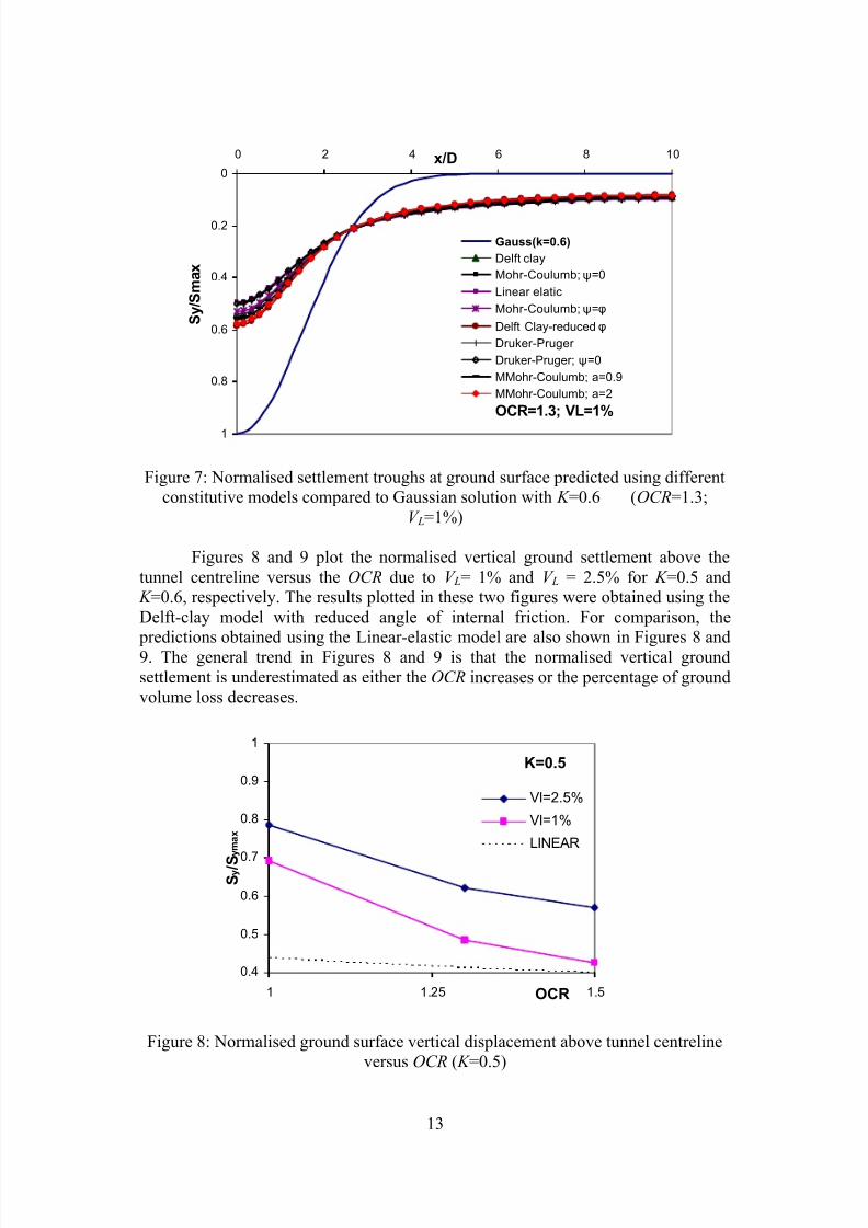
Figure 7: Normalised settlement troughs at ground surface predicted using differentconstitutive models compared to Gaussian solution with K =0.6 ( OCR=1.3;
V L=1%)
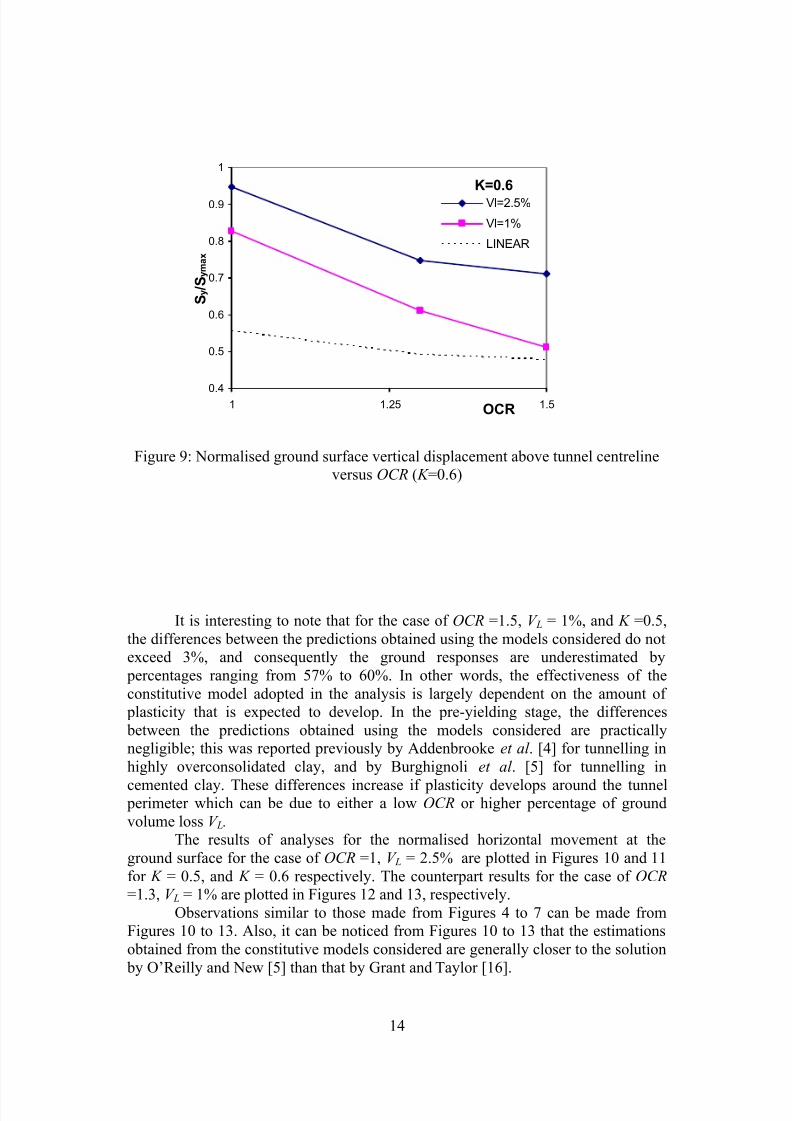
Figures 8 and 9 plot the normalised vertical ground settlement above thetunnel centreline versus the OCR due to V L= 1% and V L = 2.5% for K =0.5 and
K =0.6, respectively. The results plotted in these two figures were obtained using theDelft-clay model with reduced angle of internal friction. For comparison, the
predictions obtained using the Linear-elastic model are also shown in Figures 8 and9. The general trend in Figures 8 and 9 is that the normalised vertical groundsettlement is underestimated as either the OCR increases or the percentage of groundvolume loss decreases.
K=0.5
0.4
0.5
0.6
0.7
0.8
0.9
1
1 1.25 1.5OCR
S y / S y m a x
Vl=2.5%
Vl=1%
LINEAR
Figure 8: Normalised ground surface vertical displacement above tunnel centrelineversus OCR ( K =0.5)
8/10/2019 Applicability of elastoplastic modelling for simulating tunnel excavation
http://slidepdf.com/reader/full/applicability-of-elastoplastic-modelling-for-simulating-tunnel-excavation 14/18
14
K=0.6
0.4
0.5
0.6
0.7
0.8
0.9
1
1 1.25 1.5OCR
S y
/ S y m a x
Vl=2.5%
Vl=1%
LINEAR
Figure 9: Normalised ground surface vertical displacement above tunnel centrelineversus OCR ( K =0.6)
It is interesting to note that for the case of OCR =1.5, V L = 1%, and K =0.5,the differences between the predictions obtained using the models considered do notexceed 3%, and consequently the ground responses are underestimated by
percentages ranging from 57% to 60%. In other words, the effectiveness of theconstitutive model adopted in the analysis is largely dependent on the amount of
plasticity that is expected to develop. In the pre-yielding stage, the differences between the predictions obtained using the models considered are practicallynegligible; this was reported previously by Addenbrooke et al . [4] for tunnelling inhighly overconsolidated clay, and by Burghignoli et al . [5] for tunnelling in
cemented clay. These differences increase if plasticity develops around the tunnel perimeter which can be due to either a low OCR or higher percentage of groundvolume loss V L.
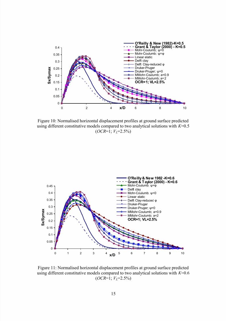
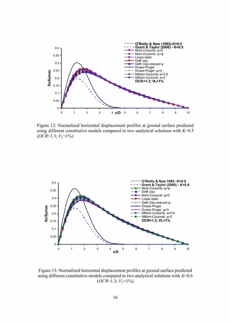
The results of analyses for the normalised horizontal movement at theground surface for the case of OCR =1, V L = 2.5% are plotted in Figures 10 and 11for K = 0.5, and K = 0.6 respectively. The counterpart results for the case of OCR =1.3, V L = 1% are plotted in Figures 12 and 13, respectively.
Observations similar to those made from Figures 4 to 7 can be made fromFigures 10 to 13. Also, it can be noticed from Figures 10 to 13 that the estimationsobtained from the constitutive models considered are generally closer to the solution
by O’Reilly and New [5] than that by Grant and Taylor [16].
8/10/2019 Applicability of elastoplastic modelling for simulating tunnel excavation
http://slidepdf.com/reader/full/applicability-of-elastoplastic-modelling-for-simulating-tunnel-excavation 15/18
15
0
0.05
0.1
0.15
0.2
0.25
0.30.35
0.4
0 2 4 6 8 10x/D
S x / S y m a x
O'Reilly & New (1982)-K=0.5Grant & Taylor (2000) - K=0.5Mohr-Coulumb; ψ =0Mohr-Coulumb; ψ =φ
Linear elaticDelft clayDelft Clay-reduced φDruker-Pruger Druker-Pruger; ψ =0MMohr-Coulumb; a=0.9MMohr-Coulumb; a=2OCR=1; VL=2.5%
Figure 10: Normalised horizontal displacement profiles at ground surface predictedusing different constitutive models compared to two analytical solutions with K =0.5
(OCR=1; V L=2.5%)
0
0.05
0.1
0.15
0.2
0.25
0.3
0.35
0.4
0.45
0 1 2 3 4 5 6 7 8 9 10x/D
S x / S y m a x
O'Reilly & New 1982 -K=0.6Grant & T aylor (2000) - K=0.6Mohr-Coulumb; ψ =φ
Delft clayMohr-Coulumb; ψ =0Linear elaticDelft Clay-reduced φDruker-Pruger Druker-Pruger; ψ =0MMohr-Coulumb; a=0.9MMohr-Coulumb; a=2OCR=1; VL=2.5%
Figure 11: Normalised horizontal displacement profiles at ground surface predictedusing different constitutive models compared to two analytical solutions with K =0.6
(OCR=1; V L=2.5%)
8/10/2019 Applicability of elastoplastic modelling for simulating tunnel excavation
http://slidepdf.com/reader/full/applicability-of-elastoplastic-modelling-for-simulating-tunnel-excavation 16/18
16
0
0.05
0.1
0.15
0.2
0.25
0.3
0.35
0.4
0 1 2 3 4 5 6 7 8 9 10x/D
S x / S y m a x
O'Reilly & New (1982)-K=0.5Grant & Taylor (2000) - K=0.5Mohr-Coulumb; ψ =0Mohr-Coulumb; ψ =φ
Linear elaticDelft clayDelft Clay-reduced φDruker-Pruger Druker-Pruger; ψ =0MMohr-Coulumb; a=0.9MMohr-Coulumb; a=2OCR=1.3; VL=1%
Figure 12: Normalised horizontal displacement profiles at ground surface predictedusing different constitutive models compared to two analytical solutions with K =0.5(OCR=1.3; V L=1%)
0
0.05
0.1
0.15
0.2
0.25
0.3
0.35
0.4
0 1 2 3 4 5 6 7 8 9 10x/D
S x / S y m a x
O'Reilly & New 1982 - K=0.6Grant & Taylor (2000) - K=0.6Mohr-Coulumb; ψ =φDelft c layMohr-Coulumb; ψ =0Linear elaticDelft Clay-reduced φDruker-Pruger Druker-Pruger; ψ =0MMohr-Coulumb; a=0.9MMohr-Coulumb; a=2OCR=1.3; VL=1%
Figure 13: Normalised horizontal displacement profiles at ground surface predictedusing different constitutive models compared to two analytical solutions with K =0.6
(OCR=1.3; V L=1%)
8/10/2019 Applicability of elastoplastic modelling for simulating tunnel excavation
http://slidepdf.com/reader/full/applicability-of-elastoplastic-modelling-for-simulating-tunnel-excavation 17/18
17
4 Conclusions
Based on the results of analyses obtained in this study, and according to thegeometric and material properties considered, a number of conclusions may bedrawn as follows.
The accuracy of the clay models used for predicting of the ground behaviourdue to tunnelling is dependent on the expected level of plasticity and therefore theaccuracy increases as either OCR decreases and/or the volume loss duringexcavation increases.
The use of the linear elasto-plastic models may not appropriate for theconstitutive modelling of clayey soils. However, better predictions for the groundresponse due to excavation can be obtained using these models if a non-associatedflow rule with ψ =0 (i.e., non-dialant material) is adopted.
A Modified Mohr-Coulomb model with a cap parameter, α , consistant withthe Cam clay model(s) may provide better predictions for ground response due toexcavation.
A Delft-clay model with a critical state parameter, M , estimated using areduced friction angle may provide resonable predictions for ground response due toexcavation.
Consideration of the yield surface in the deviatoric plane for modelling thedifference in the material strength according to the Lode’s angle seems to benecessary for accurate simulation of excavation problems.
Development of a clay constitutive model capable of accurately simulatingthe material behaviour during the pre-yielding stage is deemed necessary for a
reliable and efficient modelling of the ground behaviour due to tunnelling.The results of the present work for lightly over consolidated clays together
with the previous work carried out by Burghignoli et al . [2001-a] seem to indicatethat further work on the numerical simulation of tunnel excavtion process is stillneeded. It is the authors oponion that the discripances between the results fromnumerical solutions should not be only attributed to the limitations of theconstitiutive modlelling.
References
[1] K.M. Lee and R.K. Rowe, “Deformations caused by surface loading andtunnelling: the role of elastic anisotropy”, Geotechnique 39, No. 1, pp. 125-140, 1989.
[2] M.J. Gunn, “The prediction of surface settlement profiles due to tunnelling”,Predictive soil mechanics, proceedings of the Wroth memorial symposium, pp.304-316, 1993.
[3] B. Simpson, J.H. Atkinson and V. Jovicic, “The influence of anisotropy oncalculations of ground settlements above tunnels”, Proceedings of theinternaional symposium on geotechnical aspects of underground constructionin soft ground, London, preprint vol. pp. 511-514, 1996.
8/10/2019 Applicability of elastoplastic modelling for simulating tunnel excavation
http://slidepdf.com/reader/full/applicability-of-elastoplastic-modelling-for-simulating-tunnel-excavation 18/18
18
[4] T.I. Addenbrooke, D.M. Potts and A.M. Puzrin, “The influence of pre-failure soil stiffness on the numerical analysis of tunnel construction”Geotechnique, Vol. 47, No. 3, pp. 693-712, 1997.
[5] A. Burghignoli, S. Miliziano, and F.M. Soccodato, “Prediction of groundsettlements due to tunnelling in clayey soils using advanced constitutivesoil models: a numerical study” In Adachi et al . (eds.), Modern tunnellingscience and technology. Rotterdam-Balkema, 2001.
[6] M. Rouainia and D. M. Wood, “A kinematic hardening constitiutive modelfor natural clays with loss of structure”, Geotechnique Vol. 50, No. 2, pp.153-164, 2000.
[7] DIANA, A Finite-Element Analysis Programme, User’s Manual-Release8.1 (2nd ed.), TNO DIANA BV., Delft, The Netherlands, 2003.
[8] A.E. Groen, “Two elastoplastic models for the behaviour of soils”,Technical Report 03.21.0.31.12, Delft University of Technology, 1995.
[9] S.J.M. van Eekelen and P. van den Berg, “The Delft egg model, aconstitutive model for clay”, G. M. A. Kuslers and M. A. N. Hendriks (eds.),DIANA Computational Mechanics’94, Kluwer Academic Publisher, pp. 103-116, 1994.
[10] D.M. Wood, “Soil behaviour and critical state soil mechanics”, CambridgeUniversity press, Cambridge, 1990.
[11] P.W. Rowe, “The stress-dilatancy relation for static equilibrium of anassembly of particles in contact”, Proc. Roy. Soc., London A269, pp. 500-527,1962.
[12] T.T. Abdel-Fattah, “Material modelling and 3-D finite-element simulation for
shield tunnelling in soft clay”, Ph.D. thesis, Cairo University, Egypt, 2004.[13] B. Schmidt, “Settlements and ground movements associated with tunnelling insoils”, Ph.D. thesis, University of Illinois, Urbana, 1969.
[14] R.B. Peck, “Deep excavations and tunnelling in soft ground”, 7 th ICSMFE,State of the art volume, pp. 225-290, 1969.
[15] M.P. O’Reilly and B.M. New, “Settlements above tunnels in the unitedkingdom-their magnitude and prediction”, Proceeding of Tunnelling ’82symposium, London, pp. 173-181, 1982.
[16] R.J. Grant and R.N. Taylor, “Tunnelling-induced ground movements inclay.” Proc. Instn Civ. Engng., Vol. 143, pp. 43-55, 2000.