Embed Size (px)
Citation preview

https://support.industry.siemens.com/cs/ww/de/view/103497649
Application Description 02/2016
Using the Mobile Panels 2nd generation in Fail-Safe Applications WinCC V13 SP1, KTP700F / KTP900F Mobile, STEP 7 Safety Advanced
Warranty and Liability
KTP700 Mobile/KTP900 Mobile Anwendungsbeispiel Entry ID: 103497649, V1.1, 02/2016 2
S
iem
en
s A
G 2
01
6 A
ll ri
gh
ts r
ese
rve
d
Warranty and Liability
Note The Application Examples are not binding and do not claim to be complete with regard to configuration, equipment or any contingencies. The Application Examples do not represent customer-specific solutions. They are only intended to provide support for typical applications. You are responsible for the correct operation of the described products. These Application Examples do not relieve you of the responsibility of safely and professionally using, installing, operating and servicing equipment. When using these Application Examples, you recognize that we cannot be made liable for any damage/claims beyond the liability clause described. We reserve the right to make changes to these Application Examples at any time and without prior notice. If there are any deviations between the recommendations provided in this Application Example and other Siemens publications – e.g. catalogs – the contents of the other documents have priority.
We do not accept any liability for the information contained in this document.
Any claims against us – based on whatever legal reason – resulting from the use of the examples, information, programs, engineering and performance data etc., described in this application example will be excluded. Such an exclusion will not apply in the case of mandatory liability, e.g. under the German Product Liability Act (“Produkthaftungsgesetz”), in case of intent, gross negligence, or injury of life, body or health, guarantee for the quality of a product, fraudulent concealment of a deficiency or breach of a condition which goes to the root of the contract (“wesentliche Vertragspflichten”). The compensation for damages due to a breach of a fundamental contractual obligation is, however, limited to the foreseeable damage, typical for the type of contract, except in the event of intent or gross negligence or injury to life, body or health. The above provisions do not imply a change of the burden of proof to your detriment.
Any form of duplication or distribution of these Application Examples or excerpts hereof is prohibited without the expressed consent of Siemens Industry Sector.
Security informa-
tion
Siemens provides products and solutions with industrial security functions that support the secure operation of plants, solutions, machines, equipment and/or networks. They are important components in a holistic industrial security concept. With this in mind, Siemens’ products and solutions undergo continuous development. Siemens recommends strongly that you regularly check for product updates.
For the secure operation of Siemens products and solutions, it is necessary to take suitable preventive action (e.g. cell protection concept) and integrate each component into a holistic, state-of-the-art industrial security concept. Third-party products that may be in use should also be considered. For more information about industrial security, visit http://www.siemens.com/industrialsecurity.
To stay informed about product updates as they occur, sign up for a product-specific newsletter. For more information, visit http://support.automation.siemens.com.
Table of Contents
KTP700 Mobile/KTP900 Mobile Anwendungsbeispiel Entry ID: 103497649, V1.1, 02/2016 3
S
iem
en
s A
G 2
01
6 A
ll ri
gh
ts r
ese
rve
d
Table of Contents Warranty and Liability ................................................................................................. 2
1 Task ..................................................................................................................... 4
1.1 Introduction ........................................................................................... 4 1.2 Overview of the automation task .......................................................... 4
2 Solution............................................................................................................... 6
2.1 Overview............................................................................................... 6 2.2 Hardware setup .................................................................................... 7 2.3 Description of the core functionality ..................................................... 8 2.4 Hardware and software components ................................................. 10 2.4.1 Validity ................................................................................................ 10 2.4.2 Hardware components ....................................................................... 10 2.4.3 Software components ......................................................................... 11 2.4.4 Sample files and projects ................................................................... 11
3 Basics ............................................................................................................... 12
3.1 Log-off from the safety program ......................................................... 12 3.2 Safety notices ..................................................................................... 12 3.3 Operating modes ................................................................................ 12 3.4 Mobile Panel ....................................................................................... 13
4 Mode of Operation ........................................................................................... 14
4.1 Wiring diagram/hardware plan ........................................................... 14 4.1.1 Preliminary considerations ................................................................. 14 4.1.2 “Load circuit” solution ......................................................................... 16 4.2 Design of operating elements and contactors .................................... 17 4.3 Hardware ............................................................................................ 18 4.3.1 Mobile Panel, connection box advanced............................................ 18 4.3.2 ET 200SP, electronic module 8 F-DI .................................................. 19
5 Configuration Instruction................................................................................ 20
5.1 Circuit diagram ................................................................................... 20 5.2 Configuration ...................................................................................... 27 5.2.1 General information ............................................................................ 27 5.2.2 Hardware configuration ...................................................................... 28 5.2.3 STEP 7 standard program.................................................................. 32 5.2.4 STEP 7 program ................................................................................. 35 5.3 HMI configuration ............................................................................... 42 5.3.1 General information ............................................................................ 42 5.3.2 Acknowledging using the panel .......................................................... 43 5.4 Device settings ................................................................................... 44 5.4.1 Connection box .................................................................................. 44 5.4.2 Mobile Panel ....................................................................................... 45
6 Operating the Application ............................................................................... 48
6.1 General information ............................................................................ 48 6.2 Operating the HMI .............................................................................. 49 6.3 Operating modes ................................................................................ 50
7 Error detection ................................................................................................. 52
8 Links & Literature ............................................................................................ 54
9 History............................................................................................................... 54

1 Task
1.1 Introduction
KTP700 Mobile/KTP900 Mobile Anwendungsbeispiel Entry ID: 103497649, V1.1, 02/2016 4
S
iem
en
s A
G 2
01
6 A
ll ri
gh
ts r
ese
rve
d
1 Task
1.1 Introduction
The KTP700F/KTP900F Mobile offers versatile application options in an industrial environment. Thanks to its mobility and ruggedness, it can be used even where other HMI panels cannot be used or only with considerable effort.
Using an example, the application describes how to implement the
Emergency stop/stop button
and the enabling button
of the KTP700F Mobile in a fail-safe application.
Note Whenever this document talks about the mobile panel, it always relates to the KTP700F/KTP900F Mobile.
1.2 Overview of the automation task
The robot to be operated in an automotive plant is behind a safety fence. The safety fence can be entered through a safety door for adjustment and maintenance work.
The robot is to be operated with a mobile HMI panel.
In operating mode “Service mode” the safety door can be opened. When the safety door is open, you must actuate an additional enabling button to operate the robot.
An emergency stop button must be within reach when operating in the safety area.
The “Service mode” is selected with a key switch.
There is an external emergency stop button outside the safety fence.
The system requires a PL d for ISO 13849-1 or SIL 2 for IEX 62061 compatibility.
Figure 1-1

1 Task
1.2 Overview of the automation task
KTP700 Mobile/KTP900 Mobile Anwendungsbeispiel Entry ID: 103497649, V1.1, 02/2016 5
S
iem
en
s A
G 2
01
6 A
ll ri
gh
ts r
ese
rve
d
The following operating modes are to be implemented:
Automatic mode
– The drive is switched on with one button and switched off with another button.
Manual mode (setup mode)
– The drive is switched on/off with one button (jog mode).
Service mode (process monitoring in production)
– Like manual mode. In addition, an enabling button is required to operate the system. The system can only be activated in connection with the enabling button.
Requirements for the mobile operating device
The HMI panel must allow the following functions:
Selection of operating modes
– Manual
– Automatic
Drive on/off
Emergency stop/stop button
Operation with enabling button

2 Solution
2.1 Overview
KTP700 Mobile/KTP900 Mobile Anwendungsbeispiel Entry ID: 103497649, V1.1, 02/2016 6
S
iem
en
s A
G 2
01
6 A
ll ri
gh
ts r
ese
rve
d
2 Solution
2.1 Overview
The KTP700F Mobile (alternatively KTP900F Mobile) is used as an HMI device for this task.
The mobile panel is connected to a Connection box Advanced.
The connection box and the F-CPU communicate via PROFIsafe.
The emergency stop/stop button and enabling button are evaluated by the mobile panel directly with the F program of the connected F-CPU.
Fail-safe digital input and output modules (“F-DI” or “F-DO”) are used to
evaluate the following equipment like
external emergency stop button
safety door
key switch for “service mode”.
The system complies with PL d for ISO 13849-1 or SIL 2 for IEX 62061.
What does the application include?
The application describes the following items:
Hardware used
Circuit diagram
Program description
– STEP 7 standard program incl. F program
Operating the application
Topics not covered in this application
This application does not include a description…
of ISO 13849-1 or IEC 62061
on the subject “Machine safety”
on how to operate the WinCC TIA Portal software
Basic knowledge of these topics is assumed.
Assumed knowledge
Basic knowledge of the software and hardware used is assumed.

2 Solution
2.2 Hardware setup
KTP700 Mobile/KTP900 Mobile Anwendungsbeispiel Entry ID: 103497649, V1.1, 02/2016 7
S
iem
en
s A
G 2
01
6 A
ll ri
gh
ts r
ese
rve
d
2.2 Hardware setup
The figure below shows a schematic illustration of the main components.
Figure 2-1
1. Fail-safe CPU
2. ET 200SP interface module
3. ET 200SP, fail-safe digital input / output modules
4. ET 200SP, standard digital input / output modules
5. Contactors for fail-safe shutdown of the load circuit
6. Contactor for operational control of the robot (on/off)
7. External key switch for selecting “Service mode”
8. External push button for acknowledging fault messages
9. External emergency stop button
10. Safety door switches
11. Mobile Panel KTP700F with connection box advanced
1 2 3 5 6
7 8 9 10
11
4

2 Solution
2.3 Description of the core functionality
KTP700 Mobile/KTP900 Mobile Anwendungsbeispiel Entry ID: 103497649, V1.1, 02/2016 8
S
iem
en
s A
G 2
01
6 A
ll ri
gh
ts r
ese
rve
d
2.3 Description of the core functionality
The core functionality is the...
hardware implementation with a circuit diagram with all hardware components.
software implementation for the STEP 7 control program.
Overview and description of the circuit diagram
The figure below shows the functional setup overview. Details on the circuit diagram are described in chapter 5.
Figure 2
-A1
-S0
External
Emergency stop
Connection box
advancedKTP900F Mobile
-K10 / -K11
Safety circuit
-S1
ACK
-K100
Drive On/Off
-S10 / -S11
Safety door
-S20
Service
mode
-A2 -A3 -A4 -A5 -A6 -A7 -A1 CPU 1516F
-A2 Bus Modul
-A3 IM 155-6PN
-A4 ET 200SP, 8 F-DI
-A5 ET 200SP, 4 F-DO
-A6 ET 200SP, 8 DI
-A7 ET 200SP, 8 DO
fail-safe signals
Non fail-safe signals
PROFINET mit PROFIsafe
2 Solution
2.3 Description of the core functionality
KTP700 Mobile/KTP900 Mobile Anwendungsbeispiel Entry ID: 103497649, V1.1, 02/2016 9
S
iem
en
s A
G 2
01
6 A
ll ri
gh
ts r
ese
rve
d
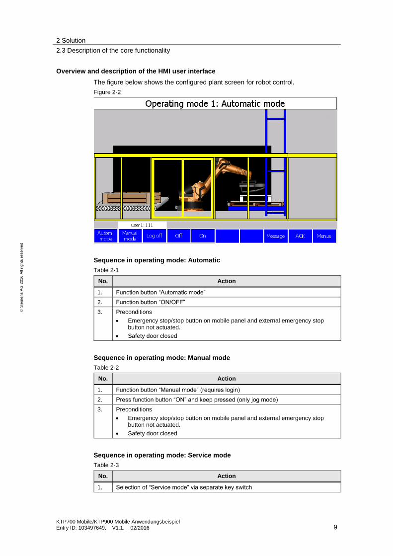
Overview and description of the HMI user interface
The figure below shows the configured plant screen for robot control.
Figure 2-2
Sequence in operating mode: Automatic
Table 2-1
No. Action
1. Function button “Automatic mode”
2. Function button “ON/OFF”
3. Preconditions
Emergency stop/stop button on mobile panel and external emergency stop button not actuated.
Safety door closed
Sequence in operating mode: Manual mode
Table 2-2
No. Action
1. Function button “Manual mode” (requires login)
2. Press function button “ON” and keep pressed (only jog mode)
3. Preconditions
Emergency stop/stop button on mobile panel and external emergency stop button not actuated.
Safety door closed
Sequence in operating mode: Service mode
Table 2-3
No. Action
1. Selection of “Service mode” via separate key switch

2 Solution
2.4 Hardware and software components
KTP700 Mobile/KTP900 Mobile Anwendungsbeispiel Entry ID: 103497649, V1.1, 02/2016 10
S
iem
en
s A
G 2
01
6 A
ll ri
gh
ts r
ese
rve
d
No. Action
2. Press enabling button on KTP and keep pressed
3. Press function button “ON” and keep pressed (only jog mode)
4. Preconditions
Emergency stop/stop button on mobile panel and external emergency stop button not actuated.
2.4 Hardware and software components
2.4.1 Validity
The application was created with the following software.
STEP 7 Professional V13 SP1 Update 2
STEP 7 Safety V13 SP1
WinCC (TIA Portal) from V13 SP1 Update 3
2.4.2 Hardware components
The application was created with the following components:
Table 2-4
Component Qty Article number Note
KTP700F Mobile 1 6AV2125-2GB23-0AX0
Connection box advanced 1 6AV2125-2AE23-0AX0
Connecting cable PN 5m 5m 6AV2181-5AF05-0AX0
DIN rail 480 mm 1 6ES7390-1AE80-0AA0
Load current supply. PS 307; AC 120/230V, DC 24V, 10A
1 6ES7307-1KA02-0AA0
CPU 1516F-3 PN/DP 1 6ES7516-3FN00-0AB0
SIMATIC S7, memory card for S7-1X00 CPU/SINAMICS, 3.3 V FLASH, 24 MBYTE
1 6ES7954-8LF02-0AA0
IM 155-6 PN HF, 1 6ES7155-6AU00-0CN0
F-DI 8x24VDC HF 1 6ES7136-6BA00-0CA0
F-DQ 4x24VDC/2A PM HF 1 6ES7136-6DB00-0CA0
DI 8x24VDC ST 1 6ES7131-6BF00-0BA0
DQ 8x24VDC/0.5A ST 1 6ES7132-6BF00-0BA0
Contactors AC-3 3KW/400V, 1OE, DC24V
4 3RT2015-1BB2
Auxiliary switch blocks 2S + 2OE 3 3RH2911-1FA22
2 Solution
2.4 Hardware and software components
KTP700 Mobile/KTP900 Mobile Anwendungsbeispiel Entry ID: 103497649, V1.1, 02/2016 11
S
iem
en
s A
G 2
01
6 A
ll ri
gh
ts r
ese
rve
d
Component Qty Article number Note
External controls 4 3SB3801-0EG3 3SB3801-0DD3
Emergency stop button
Safety door switches
Acknowledgement button
Key switch
2.4.3 Software components
Table 2-5
Component Qty Article number Note
STEP 7 Professional V13 SP1 Update 3
1 6ES7810-4CC10-0YA5 From this version
WinCC Advanced V13 SP1 Update 3
1 6AV6613-0AA51-3CA5 From this version
STEP 7 Safety Advanced V13 SP1
1 6ES7833-1FA13-0YA5 From this version
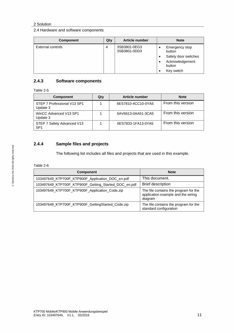
2.4.4 Sample files and projects
The following list includes all files and projects that are used in this example.
Table 2-6
Component Note
103497649_KTP700F_KTP900F_Application_DOC_en.pdf This document.
103497649_KTP700F_KTP900F_Getting_Started_DOC_en.pdf Brief description
103497649_KTP700F_KTP900F_Application_Code.zip The file contains the program for the application example and the wiring diagram
103497649_KTP700F_KTP900F_GettingStarted_Code.zip The file contains the program for the standard configuration

3 Basics
3.1 Log-off from the safety program
KTP700 Mobile/KTP900 Mobile Anwendungsbeispiel Entry ID: 103497649, V1.1, 02/2016 12
S
iem
en
s A
G 2
01
6 A
ll ri
gh
ts r
ese
rve
d
3 Basics
3.1 Log-off from the safety program
Before disconnecting the fail-safe HMI device from a connection box, you must log off the HMI device from the safety program using the system function “TerminatePROFIsafe” (1) or close the current project. After logging off, the emergency stop button and enabling button are no longer
active.
Abbildung 3-1
3.2 Safety notices
Make yourself familiar with the safety notes and the general information in the mobile panel operating instructions. You can find the operating instructions under the following link:
https://support.industry.siemens.com/cs/de/en/ps/14746/man
3.3 Operating modes
There are predefined operating modes for tool machines. In this application, the following operating modes are used.
Automatic mode (operating mode 1)
– In this operating mode, it is not possible to enter the processing area. Automatic mode must be deactivated before the door can be opened and the processing area can be entered. If the safety door is opened during automatic mode, the robot drive is shut down.
Manual mode (operating mode 2 → setup mode)
– This mode can only be selected with a password. Operators must have received specific training before they can use this operating mode. Movements are carried out in jog mode. If the operating element is let loose, the robot drive is shut down. Safety devices must be closed.
1
3 Basics
3.4 Mobile Panel
KTP700 Mobile/KTP900 Mobile Anwendungsbeispiel Entry ID: 103497649, V1.1, 02/2016 13
S
iem
en
s A
G 2
01
6 A
ll ri
gh
ts r
ese
rve
d
If the safety door is opened during manual mode, the drives are immediately shut down.
Service mode (operating mode 3 → process monitoring in production)
– In contrast to the previous operating modes, the user can monitor and control the processing with open safety device (door). To operate the robot, an additional enabling button is required. When the enabling button is let loose, the robot drive is stopped immediately.
In all three operating modes, the stationary emergency stop button and the emergency stop/stop button of the mobile panel are active.
3.4 Mobile Panel
PROFIsafe
PROFIsafe ensures F communication between both partners.
The mobile panel supports the communication via PROFIsafe. This functionality enables evaluating the emergency stop/stop button and the enabling button of the mobile panel directly in the F-CPU. Wiring additional modules is therefore not required anymore.
Connection box advanced
There are three different connection boxes for the mobile panel.
The connection box advanced used in the application can be integrated in an existing emergency stop circuit.
The assigned emergency stop circuit is not opened when unplugging the mobile panel from the connection box. When used together with PROFIsafe, the mobile panel must be logged off the network beforehand.
Emergency stop/stop button
The emergency stop/stop button signal from the mobile panel can be further processed via PROFIsafe or via suitable external evaluation devices, e.g. safety
relays.
When the mobile panel is connected to the connection box, the emergency stop/ stop button must always be active.
Depending on the operating mode, the emergency stop/stop button is lights up. In this application, the emergency stop/stop button lights up when the mobile panel is logged in to the safety program.
More information on the various operating modes can be found in the manual.
Enabling button
The enabling button signal from the mobile panel can be further processed via PROFIsafe or via suitable external evaluation devices, e.g. safety relays.
Note The enabling button is only required if prescribed by the operating mode. This would be the case, for example, in operating mode 3 “Service mode”.

4 Mode of Operation
4.1 Wiring diagram/hardware plan
KTP700 Mobile/KTP900 Mobile Anwendungsbeispiel Entry ID: 103497649, V1.1, 02/2016 14
S
iem
en
s A
G 2
01
6 A
ll ri
gh
ts r
ese
rve
d
4 Mode of Operation
4.1 Wiring diagram/hardware plan
4.1.1 Preliminary considerations
Considering the task described in chapter 1.2 “Overview of the automation task“, the hardware plan must cover three functions.
Function 1: Automatic/manual mode.
Function 2: Service mode. The enabling button evaluation from the mobile panel must be active in this operating mode.
Function 3: The external emergency stop button and the emergency stop/stop button of the mobile panel must be active in every operating mode.
The task is now to integrate these three individual functions together in one application and to achieve PL d or SIL 2.
The figure below shows the respective load circuit.
Figure 4-1
The detailed function description follows on the next page.
Two contactors (-K1 and -K2) that are controlled via the evaluation of the external emergency stop button and the emergency stop/stop button of the mobile panel. Note
Two serial contactors in the load circuit are required for the safe shutdown of the drive and to achieve PL d or SIL 2.
Two contactors (-K11 and -K21) that are controlled via the evaluation of the “enabling button”.
Depending on the selected operating mode, the operational control of the robot drive is done via a contactor (-K100 or –K101).
4 Mode of Operation
4.1 Wiring diagram/hardware plan
KTP700 Mobile/KTP900 Mobile Anwendungsbeispiel Entry ID: 103497649, V1.1, 02/2016 15
S
iem
en
s A
G 2
01
6 A
ll ri
gh
ts r
ese
rve
d
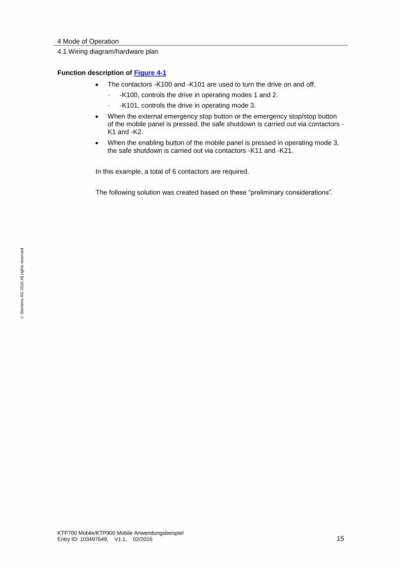
Function description of Figure 4-1
The contactors -K100 and -K101 are used to turn the drive on and off.
– -K100, controls the drive in operating modes 1 and 2.
– -K101, controls the drive in operating mode 3.
When the external emergency stop button or the emergency stop/stop button of the mobile panel is pressed, the safe shutdown is carried out via contactors -K1 and -K2.
When the enabling button of the mobile panel is pressed in operating mode 3, the safe shutdown is carried out via contactors -K11 and -K21.
In this example, a total of 6 contactors are required.
The following solution was created based on these “preliminary considerations”.
4 Mode of Operation
4.1 Wiring diagram/hardware plan
KTP700 Mobile/KTP900 Mobile Anwendungsbeispiel Entry ID: 103497649, V1.1, 02/2016 16
S
iem
en
s A
G 2
01
6 A
ll ri
gh
ts r
ese
rve
d
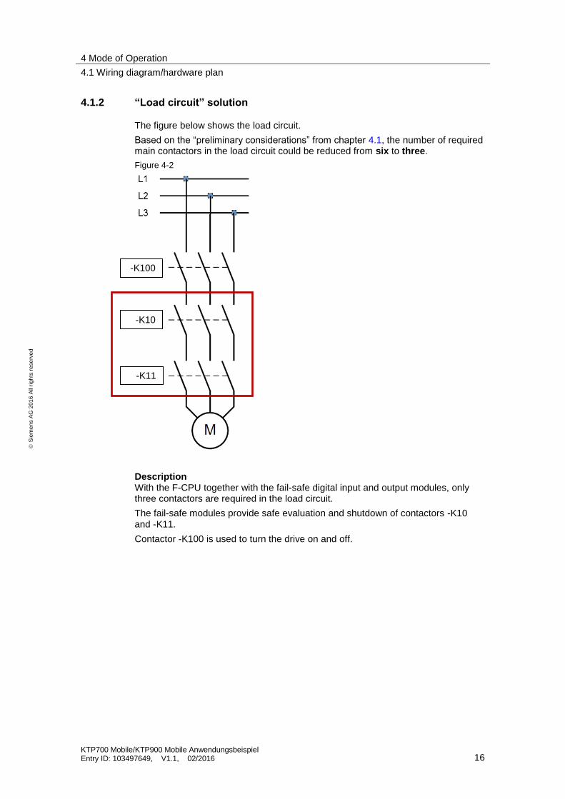
4.1.2 “Load circuit” solution
The figure below shows the load circuit.
Based on the “preliminary considerations” from chapter 4.1, the number of required main contactors in the load circuit could be reduced from six to three.
Figure 4-2
Description With the F-CPU together with the fail-safe digital input and output modules, only three contactors are required in the load circuit.
The fail-safe modules provide safe evaluation and shutdown of contactors -K10 and -K11.
Contactor -K100 is used to turn the drive on and off.
-K100
-K10
-K11
4 Mode of Operation
4.2 Design of operating elements and contactors
KTP700 Mobile/KTP900 Mobile Anwendungsbeispiel Entry ID: 103497649, V1.1, 02/2016 17
S
iem
en
s A
G 2
01
6 A
ll ri
gh
ts r
ese
rve
d
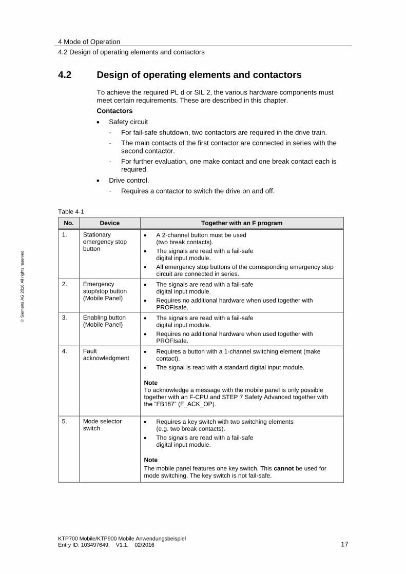
4.2 Design of operating elements and contactors
To achieve the required PL d or SIL 2, the various hardware components must meet certain requirements. These are described in this chapter.
Contactors
Safety circuit
– For fail-safe shutdown, two contactors are required in the drive train.
– The main contacts of the first contactor are connected in series with the second contactor.
– For further evaluation, one make contact and one break contact each is required.
Drive control.
– Requires a contactor to switch the drive on and off.
Table 4-1
No. Device Together with an F program
1. Stationary emergency stop button
A 2-channel button must be used (two break contacts).
The signals are read with a fail-safe digital input module.
All emergency stop buttons of the corresponding emergency stop circuit are connected in series.
2. Emergency stop/stop button (Mobile Panel)
The signals are read with a fail-safe digital input module.
Requires no additional hardware when used together with PROFIsafe.
3. Enabling button (Mobile Panel)
The signals are read with a fail-safe digital input module.
Requires no additional hardware when used together with PROFIsafe.
4. Fault acknowledgment
Requires a button with a 1-channel switching element (make contact).
The signal is read with a standard digital input module.
Note
To acknowledge a message with the mobile panel is only possible together with an F-CPU and STEP 7 Safety Advanced together with the “FB187” (F_ACK_OP).
5. Mode selector switch
Requires a key switch with two switching elements (e.g. two break contacts).
The signals are read with a fail-safe digital input module.
Note
The mobile panel features one key switch. This cannot be used for mode switching. The key switch is not fail-safe.

4 Mode of Operation
4.3 Hardware
KTP700 Mobile/KTP900 Mobile Anwendungsbeispiel Entry ID: 103497649, V1.1, 02/2016 18
S
iem
en
s A
G 2
01
6 A
ll ri
gh
ts r
ese
rve
d
No. Device Together with an F program
6. Safety door switches
Requires two switches with a 1-channel switching element (break contact).
The signals are read with a fail-safe digital input module.
7. Contactor control (safety circuit)
The contactors are controlled via a fail-safe digital output module.
8. Contactor control (drive ON/OFF)
The contactors are controlled with a standard digital output module.
9. Readback signals (contactors)
Both contactors must provide one break contact each for safe shutdown of the drive.
The break contacts are connected in series.
The signal is read with a standard digital input module.
4.3 Hardware
4.3.1 Mobile Panel, connection box advanced
X10 interface assignment
Terminal strip X10, 12-pole: 24V DC voltage supply
Figure 4-3
Note The application evaluates the emergency stop/stop button and the enabling button via PROFIsafe.
4 Mode of Operation
4.3 Hardware
KTP700 Mobile/KTP900 Mobile Anwendungsbeispiel Entry ID: 103497649, V1.1, 02/2016 19
S
iem
en
s A
G 2
01
6 A
ll ri
gh
ts r
ese
rve
d
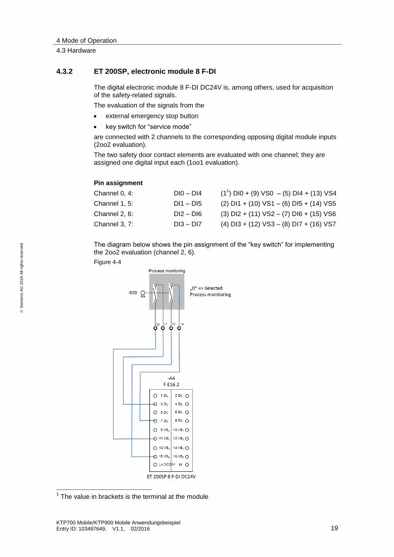
4.3.2 ET 200SP, electronic module 8 F-DI
The digital electronic module 8 F-DI DC24V is, among others, used for acquisition of the safety-related signals.
The evaluation of the signals from the
external emergency stop button
key switch for “service mode”
are connected with 2 channels to the corresponding opposing digital module inputs (2oo2 evaluation).
The two safety door contact elements are evaluated with one channel; they are assigned one digital input each (1oo1 evaluation).
Pin assignment
Channel 0, 4: DI0 – DI4 (11) DI0 + (9) VS0 – (5) DI4 + (13) VS4
Channel 1, 5: DI1 – DI5 (2) DI1 + (10) VS1 – (6) DI5 + (14) VS5
Channel 2, 6: DI2 – DI6 (3) DI2 + (11) VS2 – (7) DI6 + (15) VS6
Channel 3, 7: DI3 – DI7 (4) DI3 + (12) VS3 – (8) DI7 + (16) VS7
The diagram below shows the pin assignment of the “key switch” for implementing the 2oo2 evaluation (channel 2, 6).
Figure 4-4
1 The value in brackets is the terminal at the module
5 Configuration Instruction
5.1 Circuit diagram
KTP700 Mobile/KTP900 Mobile Anwendungsbeispiel Entry ID: 103497649, V1.1, 02/2016 20
S
iem
en
s A
G 2
01
6 A
ll ri
gh
ts r
ese
rve
d
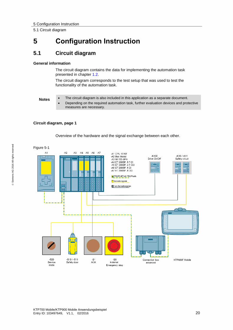
5 Configuration Instruction
5.1 Circuit diagram
General information
The circuit diagram contains the data for implementing the automation task presented in chapter 1.2.
The circuit diagram corresponds to the test setup that was used to test the functionality of the automation task.
Notes The circuit diagram is also included in this application as a separate document.
Depending on the required automation task, further evaluation devices and protective measures are necessary.
Circuit diagram, page 1
Overview of the hardware and the signal exchange between each other.
Figure 5-1

5 Configuration Instruction
5.1 Circuit diagram
KTP700 Mobile/KTP900 Mobile Anwendungsbeispiel Entry ID: 103497649, V1.1, 02/2016 21
S
iem
en
s A
G 2
01
6 A
ll ri
gh
ts r
ese
rve
d
Circuit diagram, page 2
Overview of the load circuit.
Contactor -K100 is used to turn the robot drive on and off.
Contactors -K10 and -K11 (safety chain) are used to safely switch off the robot drive.
Figure 5-2

5 Configuration Instruction
5.1 Circuit diagram
KTP700 Mobile/KTP900 Mobile Anwendungsbeispiel Entry ID: 103497649, V1.1, 02/2016 22
S
iem
en
s A
G 2
01
6 A
ll ri
gh
ts r
ese
rve
d
Circuit diagram, page 3
This page shows how to connect the external emergency stop button to the F-DI 8 module.
The pin assignment shows the implementation of the 2oo2 evaluation (channel 0, 4).
The emergency stop/stop button of the Mobile Panel are evaluated directly in the F-CPU.
Figure 5-3
Circuit diagram, page 4
The enabling button is evaluated via PROFIsafe.
Figure 5-4

5 Configuration Instruction
5.1 Circuit diagram
KTP700 Mobile/KTP900 Mobile Anwendungsbeispiel Entry ID: 103497649, V1.1, 02/2016 23
S
iem
en
s A
G 2
01
6 A
ll ri
gh
ts r
ese
rve
d
Circuit diagram, page 5
This page shows how to
connect the “service mode” key switch for to the F-DI module. The pin assignment shows the implementation of the 2oo2 evaluation (channel 2, 6).
connect the safety door switch (switch -S10 and -S11) to the F-DI module. The pin assignment shows the implementation of the 1oo1 evaluation (channel 3 and channel 7). The discrepancy analysis is done in the control program via the standard function block FB217 “F_SFDOOR”.
Note Each channel of the F-DI module can be parameterized separately.
Figure 5-5
5 Configuration Instruction
5.1 Circuit diagram
KTP700 Mobile/KTP900 Mobile Anwendungsbeispiel Entry ID: 103497649, V1.1, 02/2016 24
S
iem
en
s A
G 2
01
6 A
ll ri
gh
ts r
ese
rve
d
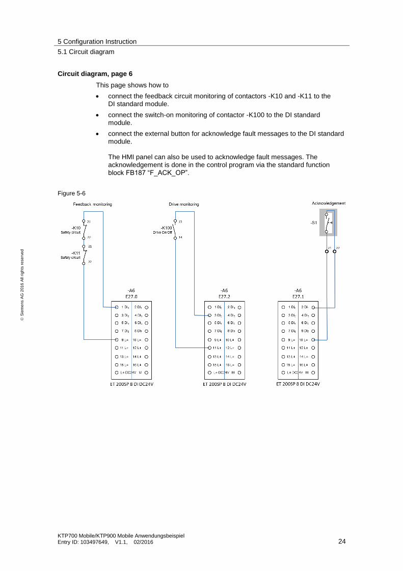
Circuit diagram, page 6
This page shows how to
connect the feedback circuit monitoring of contactors -K10 and -K11 to the DI standard module.
connect the switch-on monitoring of contactor -K100 to the DI standard module.
connect the external button for acknowledge fault messages to the DI standard module. The HMI panel can also be used to acknowledge fault messages. The acknowledgement is done in the control program via the standard function block FB187 “F_ACK_OP”.
Figure 5-6

5 Configuration Instruction
5.1 Circuit diagram
KTP700 Mobile/KTP900 Mobile Anwendungsbeispiel Entry ID: 103497649, V1.1, 02/2016 25
S
iem
en
s A
G 2
01
6 A
ll ri
gh
ts r
ese
rve
d
Circuit diagram, page 7
This page shows how to connect contactors –K10 and –K11 via the F-DO module.
The contactors are used to safely switch off the load circuit with the robot drive.
Figure 5-7

5 Configuration Instruction
5.1 Circuit diagram
KTP700 Mobile/KTP900 Mobile Anwendungsbeispiel Entry ID: 103497649, V1.1, 02/2016 26
S
iem
en
s A
G 2
01
6 A
ll ri
gh
ts r
ese
rve
d
Circuit diagram, page 8
This page shows how to control contactor –K100 for normal startup/shutdown of the robot drive.
The contactor is controlled with a standard digital output module.
Figure 5-8
Circuit diagram, page 9
This page shows the voltage supply for ET200 SP
Figure 5-9

5 Configuration Instruction
5.2 Configuration
KTP700 Mobile/KTP900 Mobile Anwendungsbeispiel Entry ID: 103497649, V1.1, 02/2016 27
S
iem
en
s A
G 2
01
6 A
ll ri
gh
ts r
ese
rve
d
5.2 Configuration
5.2.1 General information
STEP 7 program
The STEP 7 program contains a standard STEP 7 program and an F program.
The standard program is used to control the robot drive.
The F program is used to evaluate the safety-related functions.
An F_FB_KTP_Mobile must be parameterized for each Mobile Panel.
An F_FB_KTP_RNG must be parameterized for each connection box.
HMI configuration
The HMI configuration contains all required functions for robot control. The robots movements are animated with a graphics list.
Program information
The following measures have been implemented in the STEP 7 program to avoid the risk of misuse by forbidden fixation of the enabling button.
The enabling button must be released within a specified time frame and then be returned to the “enabling” position. The time frame must be specified based on the activity of the monitoring system.
It is forbidden to use the enabling button to start the drive.
– The enabling button must always be pressed before starting the drive.
– When the “Drive on” button is pressed and the enabling button is pressed next, the drive will not be activated.
Note Please note the safety information and general information in the Mobile Panel manual. (You can find the operating instructions under the following link https://support.industry.siemens.com/cs/de/en/ps/14746/man)
Excerpts from STEP 7 and from HMI configuration are described below in more detail.
5 Configuration Instruction
5.2 Configuration
KTP700 Mobile/KTP900 Mobile Anwendungsbeispiel Entry ID: 103497649, V1.1, 02/2016 28
S
iem
en
s A
G 2
01
6 A
ll ri
gh
ts r
ese
rve
d
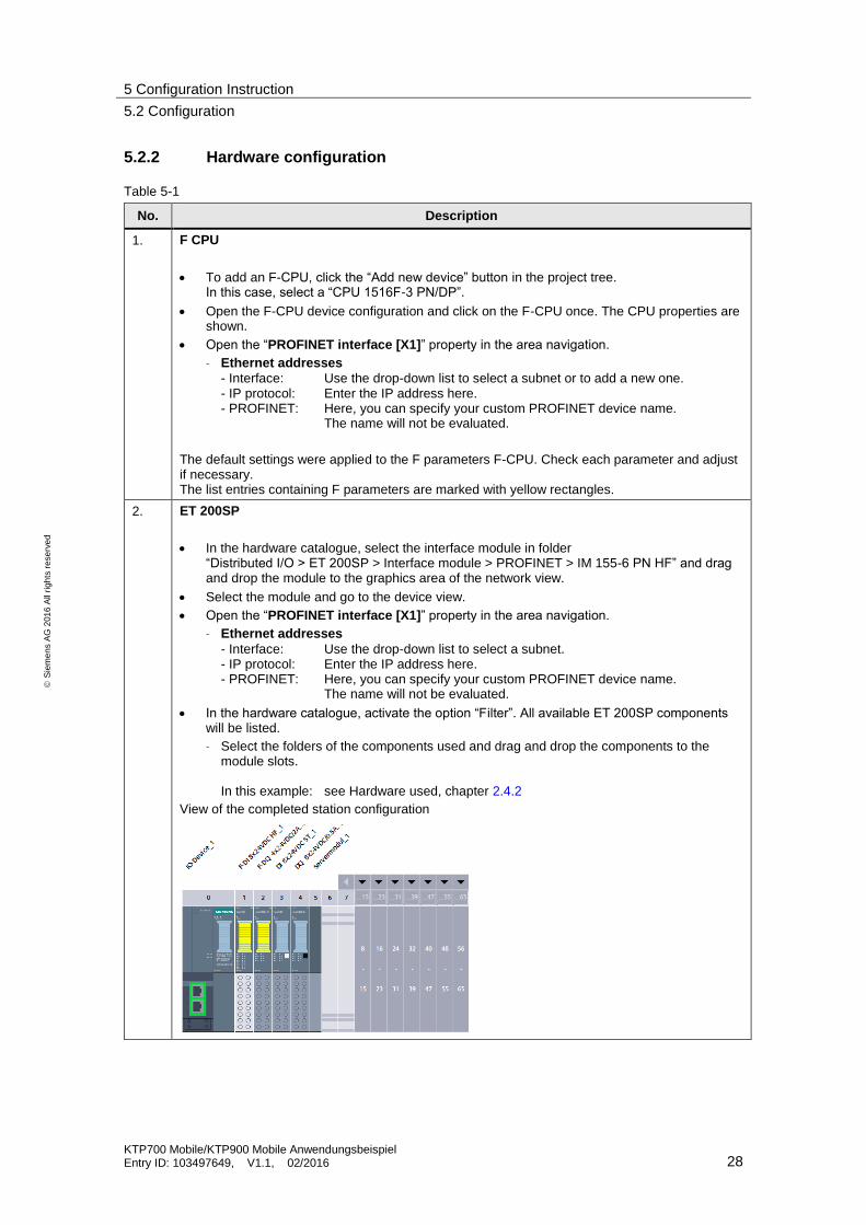
5.2.2 Hardware configuration
Table 5-1
No. Description
1. F CPU
To add an F-CPU, click the “Add new device” button in the project tree. In this case, select a “CPU 1516F-3 PN/DP”.
Open the F-CPU device configuration and click on the F-CPU once. The CPU properties are shown.
Open the “PROFINET interface [X1]” property in the area navigation.
– Ethernet addresses
- Interface: Use the drop-down list to select a subnet or to add a new one. - IP protocol: Enter the IP address here. - PROFINET: Here, you can specify your custom PROFINET device name. The name will not be evaluated.
The default settings were applied to the F parameters F-CPU. Check each parameter and adjust if necessary. The list entries containing F parameters are marked with yellow rectangles.
2. ET 200SP
In the hardware catalogue, select the interface module in folder “Distributed I/O > ET 200SP > Interface module > PROFINET > IM 155-6 PN HF” and drag and drop the module to the graphics area of the network view.
Select the module and go to the device view.
Open the “PROFINET interface [X1]” property in the area navigation.
– Ethernet addresses
- Interface: Use the drop-down list to select a subnet. - IP protocol: Enter the IP address here. - PROFINET: Here, you can specify your custom PROFINET device name. The name will not be evaluated.
In the hardware catalogue, activate the option “Filter”. All available ET 200SP components will be listed.
– Select the folders of the components used and drag and drop the components to the module slots. In this example: see Hardware used, chapter 2.4.2
View of the completed station configuration
5 Configuration Instruction
5.2 Configuration
KTP700 Mobile/KTP900 Mobile Anwendungsbeispiel Entry ID: 103497649, V1.1, 02/2016 29
S
iem
en
s A
G 2
01
6 A
ll ri
gh
ts r
ese
rve
d
No. Description
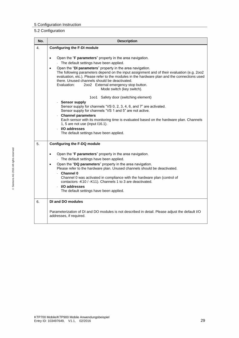
4. Configuring the F-DI module
Open the “F parameters” property in the area navigation.
– The default settings have been applied.
Open the “DI parameters” property in the area navigation.
The following parameters depend on the input assignment and of their evaluation (e.g. 2oo2 evaluation, etc.). Please refer to the modules in the hardware plan and the connections used there. Unused channels should be deactivated. Evaluation: 2oo2 External emergency stop button. Mode switch (key switch). 1oo1 Safety door (switching element)
– Sensor supply
Sensor supply for channels “VS 0, 2, 3, 4, 6, and 7” are activated. Sensor supply for channels “VS 1 and 5” are not active.
– Channel parameters
Each sensor with its monitoring time is evaluated based on the hardware plan. Channels 1, 5 are not use (input I16.1).
– I/O addresses The default settings have been applied.
5. Configuring the F-DQ module
Open the “F parameters” property in the area navigation.
– The default settings have been applied.
Open the “DQ parameters” property in the area navigation.
Please refer to the hardware plan. Unused channels should be deactivated.
– Channel 0
Channel 0 was activated in compliance with the hardware plan (control of contactors -K10 / -K11). Channels 1 to 3 are deactivated.
– I/O addresses The default settings have been applied.
6. DI and DO modules
Parameterization of DI and DO modules is not described in detail. Please adjust the default I/O addresses, if required.
5 Configuration Instruction
5.2 Configuration
KTP700 Mobile/KTP900 Mobile Anwendungsbeispiel Entry ID: 103497649, V1.1, 02/2016 30
S
iem
en
s A
G 2
01
6 A
ll ri
gh
ts r
ese
rve
d
No. Description
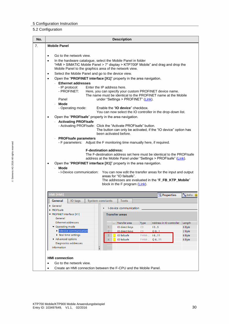
7. Mobile Panel
Go to the network view.
In the hardware catalogue, select the Mobile Panel in folder “HMI > SIMATIC Mobile Panel > 7“ display > KTP700F Mobile” and drag and drop the Mobile Panel to the graphics area of the network view.
Select the Mobile Panel and go to the device view.
Open the “PROFINET interface [X1]” property in the area navigation.
– Ethernet addresses
- IP protocol: Enter the IP address here. - PROFINET: Here, you can specify your custom PROFINET device name. The name must be identical to the PROFINET name at the Mobile Panel under “Settings > PROFINET” (Link).
– Mode - Operating mode: Enable the “IO device” checkbox. You can now select the IO controller in the drop-down list.
Open the “PROFIsafe” property in the area navigation.
– Activating PROFIsafe
- Activating PROFIsafe: Click the “Activate PROFIsafe” button. The button can only be activated, if the “IO device” option has been activated before.
– PROFIsafe parameters
- F parameters: Adjust the F monitoring time manually here, if required. F-destination address:
The F-destination address set here must be identical to the PROFIsafe address at the Mobile Panel under “Settings > PROFIsafe” (Link).
Open the “PROFINET interface [X1]” property in the area navigation.
– Mode
- I-Device communication: You can now edit the transfer areas for the input and output areas for “IO failsafe”. The addresses are evaluated in the “F_FB_KTP_Mobile” block in the F program (Link).
HMI connection
Go to the network view.
Create an HMI connection between the F-CPU and the Mobile Panel.
5 Configuration Instruction
5.2 Configuration
KTP700 Mobile/KTP900 Mobile Anwendungsbeispiel Entry ID: 103497649, V1.1, 02/2016 31
S
iem
en
s A
G 2
01
6 A
ll ri
gh
ts r
ese
rve
d
No. Description
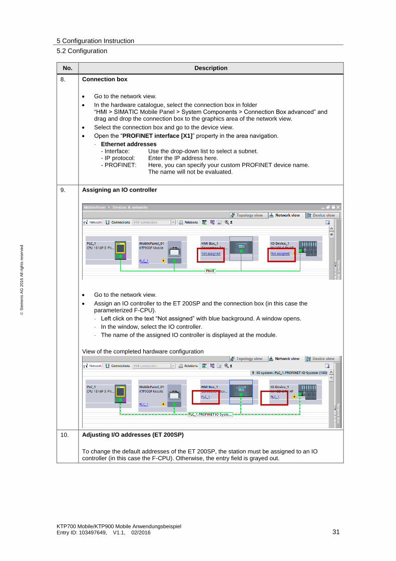
8. Connection box
Go to the network view.
In the hardware catalogue, select the connection box in folder “HMI > SIMATIC Mobile Panel > System Components > Connection Box advanced” and drag and drop the connection box to the graphics area of the network view.
Select the connection box and go to the device view.
Open the “PROFINET interface [X1]” property in the area navigation.
– Ethernet addresses
- Interface: Use the drop-down list to select a subnet. - IP protocol: Enter the IP address here. - PROFINET: Here, you can specify your custom PROFINET device name. The name will not be evaluated.
9. Assigning an IO controller
Go to the network view.
Assign an IO controller to the ET 200SP and the connection box (in this case the parameterized F-CPU).
– Left click on the text “Not assigned” with blue background. A window opens.
– In the window, select the IO controller.
– The name of the assigned IO controller is displayed at the module.
View of the completed hardware configuration
10. Adjusting I/O addresses (ET 200SP)
To change the default addresses of the ET 200SP, the station must be assigned to an IO controller (in this case the F-CPU). Otherwise, the entry field is grayed out.
5 Configuration Instruction
5.2 Configuration
KTP700 Mobile/KTP900 Mobile Anwendungsbeispiel Entry ID: 103497649, V1.1, 02/2016 32
S
iem
en
s A
G 2
01
6 A
ll ri
gh
ts r
ese
rve
d
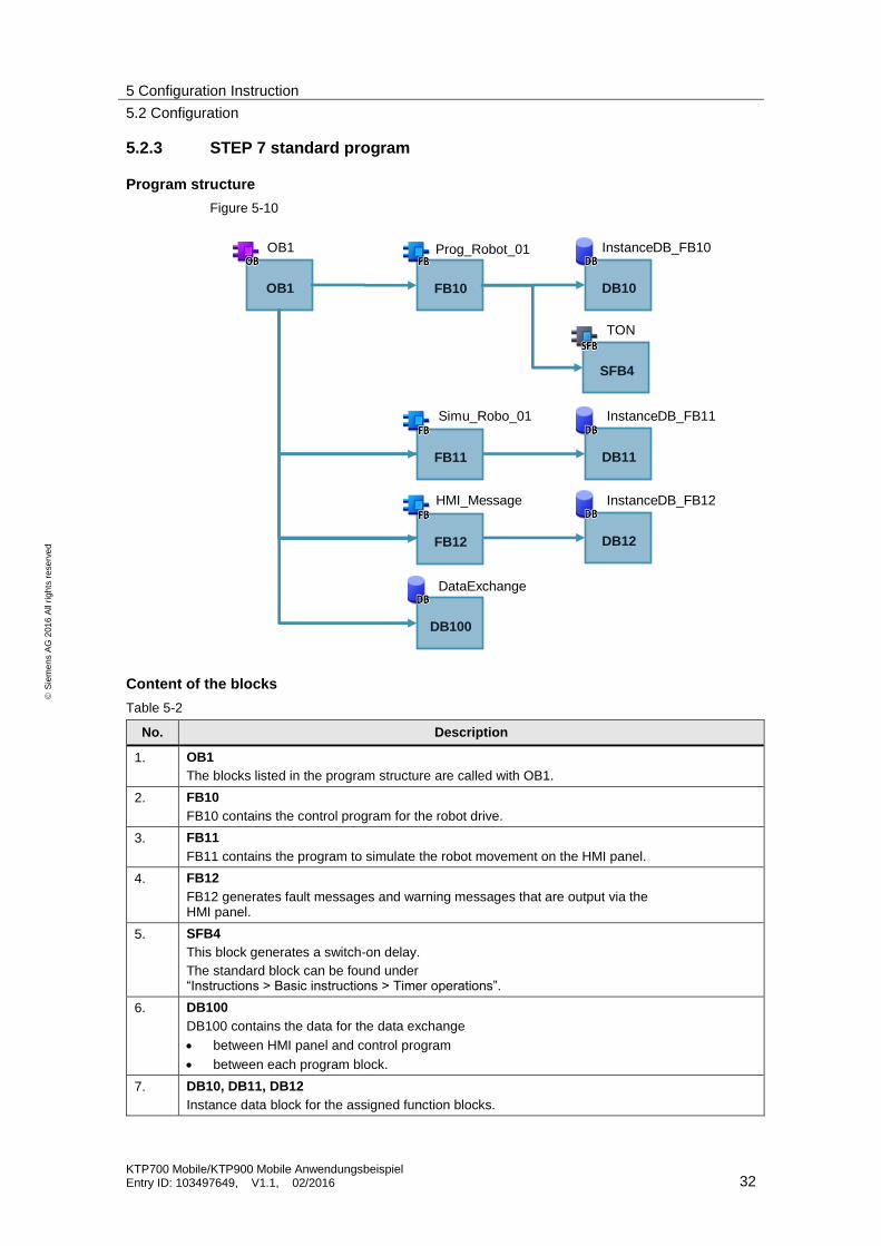
5.2.3 STEP 7 standard program
Program structure
Figure 5-10
OB1 FB10 DB10
SFB4
DB11
DB12
DB100
Prog_Robot_01
Simu_Robo_01
HMI_Message
InstanceDB_FB10
InstanceDB_FB11
InstanceDB_FB12
DataExchange
TON
FB11
FB12
OB1
Content of the blocks
Table 5-2
No. Description
1. OB1
The blocks listed in the program structure are called with OB1.
2. FB10
FB10 contains the control program for the robot drive.
3. FB11
FB11 contains the program to simulate the robot movement on the HMI panel.
4. FB12
FB12 generates fault messages and warning messages that are output via the HMI panel.
5. SFB4
This block generates a switch-on delay.
The standard block can be found under “Instructions > Basic instructions > Timer operations”.
6. DB100
DB100 contains the data for the data exchange
between HMI panel and control program
between each program block.
7. DB10, DB11, DB12
Instance data block for the assigned function blocks.

5 Configuration Instruction
5.2 Configuration
KTP700 Mobile/KTP900 Mobile Anwendungsbeispiel Entry ID: 103497649, V1.1, 02/2016 33
S
iem
en
s A
G 2
01
6 A
ll ri
gh
ts r
ese
rve
d
Description of the blocks
FB10, Prog_Robot-01
FB10 contains the essential program steps to control the robot drive.
Table 5-3
No. Description
1. Network 4, automatic mode
To ensure that the function button for switching on the drive cannot be “fixated”, the signal is polled via a positive edge.
2. Network 5, manual mode
To ensure that the function button for switching on the drive cannot be “fixated”, the signal is polled via a positive edge.
In “Manual mode”, the system is switched on/off with a function button -> jog mode.
3. Network 6, service mode
To ensure that the function button for switching on the drive cannot be “fixated”, the signal is polled via a positive edge.
In “Service mode”, the system is switched on/off with a function button -> jog mode.
4. Network 8, feedback circuit monitoring
The network monitors possible functional errors of contactor –K100 “Robot drive on/off”. To do this, one make contact was wired from the contactor to one input. When the drive is off and the input signals a “1 signal”, for example, then there is a malfunction.
Note The monitoring is not a safety-relevant function. It is not used to safely shut down the drive. Safe shutdown is evaluated by the F program.
5. Network 9, output of the selected operating mode
The current operating mode is output in a text list at the HMI panel. The evaluation is performed in this network.
6. Network 10, output of Safety door open/closed
The HMI panel shows an animation of the open or closed safety door. The evaluation is performed in this network.
5 Configuration Instruction
5.2 Configuration
KTP700 Mobile/KTP900 Mobile Anwendungsbeispiel Entry ID: 103497649, V1.1, 02/2016 34
S
iem
en
s A
G 2
01
6 A
ll ri
gh
ts r
ese
rve
d
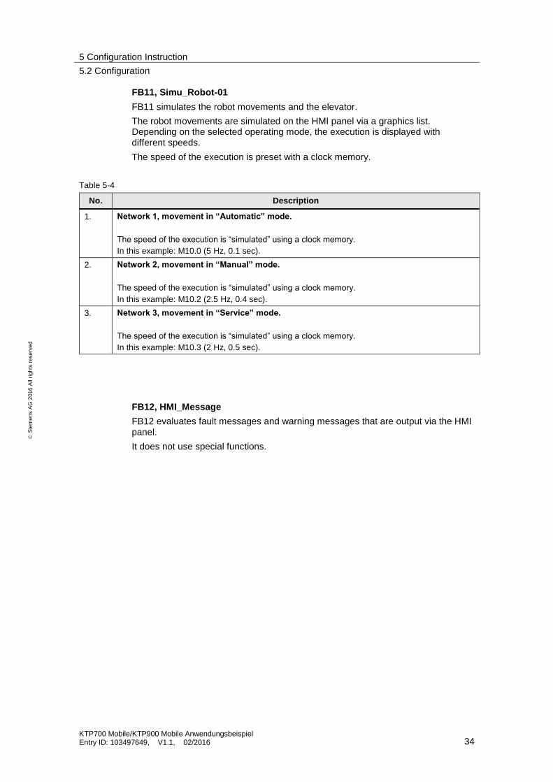
FB11, Simu_Robot-01
FB11 simulates the robot movements and the elevator.
The robot movements are simulated on the HMI panel via a graphics list. Depending on the selected operating mode, the execution is displayed with different speeds.
The speed of the execution is preset with a clock memory.
Table 5-4
No. Description
1. Network 1, movement in “Automatic” mode.
The speed of the execution is “simulated” using a clock memory.
In this example: M10.0 (5 Hz, 0.1 sec).
2. Network 2, movement in “Manual” mode.
The speed of the execution is “simulated” using a clock memory.
In this example: M10.2 (2.5 Hz, 0.4 sec).
3. Network 3, movement in “Service” mode.
The speed of the execution is “simulated” using a clock memory.
In this example: M10.3 (2 Hz, 0.5 sec).
FB12, HMI_Message
FB12 evaluates fault messages and warning messages that are output via the HMI panel.
It does not use special functions.
5 Configuration Instruction
5.2 Configuration
KTP700 Mobile/KTP900 Mobile Anwendungsbeispiel Entry ID: 103497649, V1.1, 02/2016 35
S
iem
en
s A
G 2
01
6 A
ll ri
gh
ts r
ese
rve
d
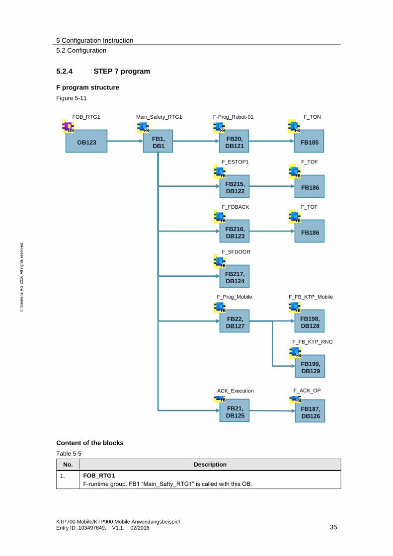
5.2.4 STEP 7 program
F program structure
Figure 5-11
OB123 FB185FB20,
DB121
FB1,
DB1
FB186FB215,
DB122
FB186FB216,
DB123
FB217,
DB124
FB187,
DB126
FB21,
DB125
FOB_RTG1
F_ESTOP1
Main_Safety_RTG1 F_TONF-Prog_Robot-01
F_TOF
F_FDBACK F_TOF
F_SFDOOR
ACK_Execution F_ACK_OP
FB198,
DB128
FB199,
DB129
FB22,
DB127
F_Prog_Mobile
F_FB_KTP_RNG
F_FB_KTP_Mobile
Content of the blocks
Table 5-5
No. Description
1. FOB_RTG1
F-runtime group. FB1 “Main_Safty_RTG1” is called with this OB.
5 Configuration Instruction
5.2 Configuration
KTP700 Mobile/KTP900 Mobile Anwendungsbeispiel Entry ID: 103497649, V1.1, 02/2016 36
S
iem
en
s A
G 2
01
6 A
ll ri
gh
ts r
ese
rve
d
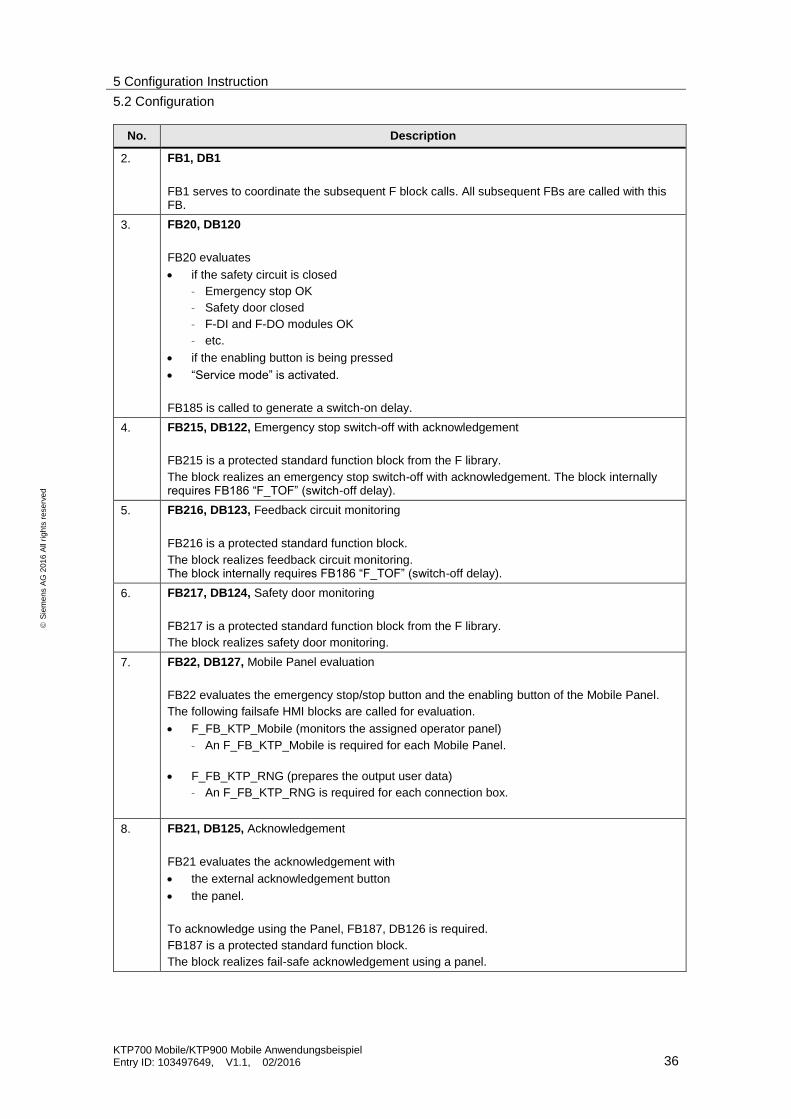
No. Description
2. FB1, DB1
FB1 serves to coordinate the subsequent F block calls. All subsequent FBs are called with this FB.
3. FB20, DB120
FB20 evaluates
if the safety circuit is closed
– Emergency stop OK
– Safety door closed
– F-DI and F-DO modules OK
– etc.
if the enabling button is being pressed
“Service mode” is activated.
FB185 is called to generate a switch-on delay.
4. FB215, DB122, Emergency stop switch-off with acknowledgement
FB215 is a protected standard function block from the F library.
The block realizes an emergency stop switch-off with acknowledgement. The block internally requires FB186 “F_TOF” (switch-off delay).
5. FB216, DB123, Feedback circuit monitoring
FB216 is a protected standard function block.
The block realizes feedback circuit monitoring. The block internally requires FB186 “F_TOF” (switch-off delay).
6. FB217, DB124, Safety door monitoring
FB217 is a protected standard function block from the F library.
The block realizes safety door monitoring.
7. FB22, DB127, Mobile Panel evaluation
FB22 evaluates the emergency stop/stop button and the enabling button of the Mobile Panel.
The following failsafe HMI blocks are called for evaluation.
F_FB_KTP_Mobile (monitors the assigned operator panel)
– An F_FB_KTP_Mobile is required for each Mobile Panel.
F_FB_KTP_RNG (prepares the output user data)
– An F_FB_KTP_RNG is required for each connection box.
8. FB21, DB125, Acknowledgement
FB21 evaluates the acknowledgement with
the external acknowledgement button
the panel.
To acknowledge using the Panel, FB187, DB126 is required.
FB187 is a protected standard function block.
The block realizes fail-safe acknowledgement using a panel.

5 Configuration Instruction
5.2 Configuration
KTP700 Mobile/KTP900 Mobile Anwendungsbeispiel Entry ID: 103497649, V1.1, 02/2016 37
S
iem
en
s A
G 2
01
6 A
ll ri
gh
ts r
ese
rve
d
No. Description
9. DB120
DB120 contains the data for the data exchange
between the standard program and the F program
within the F program.
10. DB1, DB121, DB122, DB123, DB124, DB125, DB126, DB127, DB128, DB129
Instance data block for the assigned function blocks.
11. OB82, OB83, OB86
These blocks are required in connection with the F program. The blocks do not contain program elements.
Note Please refer to the online help for more information on the standard function blocks used.
F-runtime group (FOB_RTG1, OB123)
When adding the F-CPU, STEP 7 Safety automatically adds an F-runtime group. Open the “Program blocks” folder to see the F blocks for the F-runtime group.
F blocks of the F-runtime group
Main_Safety [FB1]
Main_Safety_DB [DB1])
Figure 5-12
FB1, Main_Safety_RTG1
FB1 calls all F function blocks and parameterizes them according to the input/output parameters.
There are not “logic connections” in this FB.
Note Please make sure that the acknowledgement, in this case FB21, is always called up at the end.
5 Configuration Instruction
5.2 Configuration
KTP700 Mobile/KTP900 Mobile Anwendungsbeispiel Entry ID: 103497649, V1.1, 02/2016 38
S
iem
en
s A
G 2
01
6 A
ll ri
gh
ts r
ese
rve
d
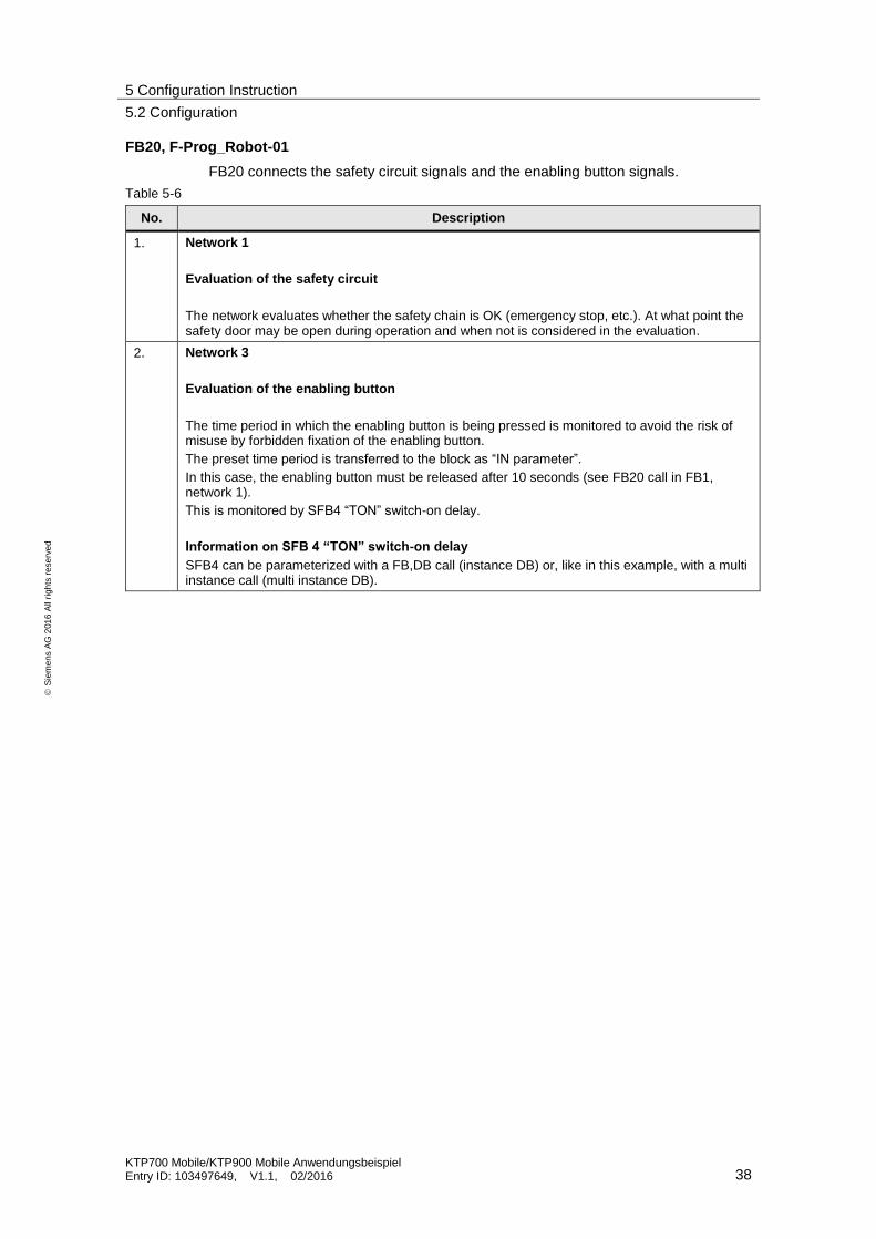
FB20, F-Prog_Robot-01
FB20 connects the safety circuit signals and the enabling button signals.
Table 5-6
No. Description
1. Network 1
Evaluation of the safety circuit
The network evaluates whether the safety chain is OK (emergency stop, etc.). At what point the safety door may be open during operation and when not is considered in the evaluation.
2. Network 3
Evaluation of the enabling button
The time period in which the enabling button is being pressed is monitored to avoid the risk of misuse by forbidden fixation of the enabling button.
The preset time period is transferred to the block as “IN parameter”.
In this case, the enabling button must be released after 10 seconds (see FB20 call in FB1, network 1).
This is monitored by SFB4 “TON” switch-on delay.
Information on SFB 4 “TON” switch-on delay
SFB4 can be parameterized with a FB,DB call (instance DB) or, like in this example, with a multi instance call (multi instance DB).

5 Configuration Instruction
5.2 Configuration
KTP700 Mobile/KTP900 Mobile Anwendungsbeispiel Entry ID: 103497649, V1.1, 02/2016 39
S
iem
en
s A
G 2
01
6 A
ll ri
gh
ts r
ese
rve
d
FB21, ACK_Execution
FB21 evaluates the acknowledgement.
Table 5-7
No. Description
1. Network 1
Acknowledging using the panel
The standard function block “FB187” (F_ACK_OP) makes safe acknowledgement via the panel. For this, two buttons are required at the HMI panel (see Link).
A tag from a standard DB is used as “IN parameter”.
Detailed information on fail-safe acknowledgement can be found in the STEP 7 online help.
2. Network 2
Evaluation and output of the acknowledgement
The acknowledgement signal from the “external acknowledgement button” and the “Acknowledgement” from the panel are combined via the network.
It is output to three outputs.
5 Configuration Instruction
5.2 Configuration
KTP700 Mobile/KTP900 Mobile Anwendungsbeispiel Entry ID: 103497649, V1.1, 02/2016 40
S
iem
en
s A
G 2
01
6 A
ll ri
gh
ts r
ese
rve
d
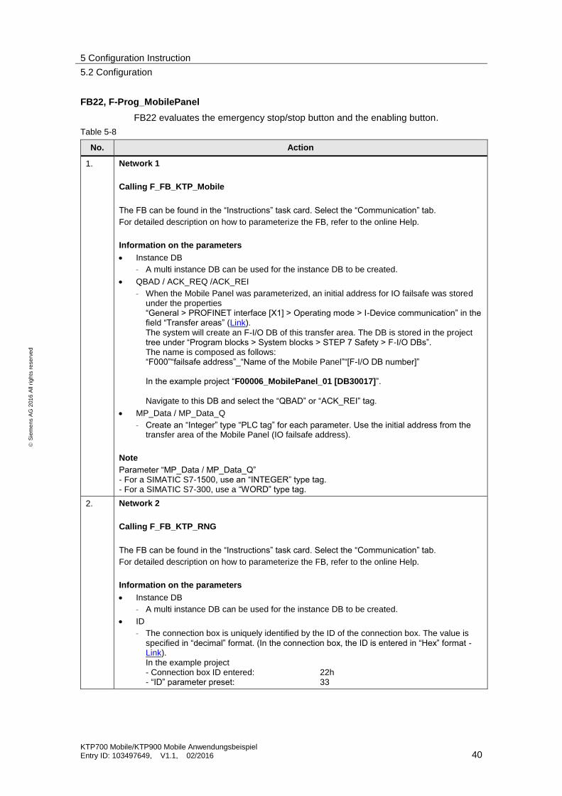
FB22, F-Prog_MobilePanel
FB22 evaluates the emergency stop/stop button and the enabling button.
Table 5-8
No. Action
1. Network 1
Calling F_FB_KTP_Mobile
The FB can be found in the “Instructions” task card. Select the “Communication” tab.
For detailed description on how to parameterize the FB, refer to the online Help.
Information on the parameters
Instance DB
– A multi instance DB can be used for the instance DB to be created.
QBAD / ACK_REQ /ACK_REI
– When the Mobile Panel was parameterized, an initial address for IO failsafe was stored under the properties “General > PROFINET interface [X1] > Operating mode > I-Device communication” in the field “Transfer areas” (Link). The system will create an F-I/O DB of this transfer area. The DB is stored in the project tree under “Program blocks > System blocks > STEP 7 Safety > F-I/O DBs”. The name is composed as follows: “F000”“failsafe address”_“Name of the Mobile Panel”“[F-I/O DB number]” In the example project “F00006_MobilePanel_01 [DB30017]”.
Navigate to this DB and select the “QBAD” or “ACK_REI” tag.
MP_Data / MP_Data_Q
– Create an “Integer” type “PLC tag” for each parameter. Use the initial address from the transfer area of the Mobile Panel (IO failsafe address).
Note
Parameter “MP_Data / MP_Data_Q” - For a SIMATIC S7-1500, use an “INTEGER” type tag. - For a SIMATIC S7-300, use a “WORD” type tag.
2. Network 2
Calling F_FB_KTP_RNG
The FB can be found in the “Instructions” task card. Select the “Communication” tab.
For detailed description on how to parameterize the FB, refer to the online Help.
Information on the parameters
Instance DB
– A multi instance DB can be used for the instance DB to be created.
ID
– The connection box is uniquely identified by the ID of the connection box. The value is specified in “decimal” format. (In the connection box, the ID is entered in “Hex” format - Link). In the example project - Connection box ID entered: 22h - “ID” parameter preset: 33
5 Configuration Instruction
5.2 Configuration
KTP700 Mobile/KTP900 Mobile Anwendungsbeispiel Entry ID: 103497649, V1.1, 02/2016 41
S
iem
en
s A
G 2
01
6 A
ll ri
gh
ts r
ese
rve
d
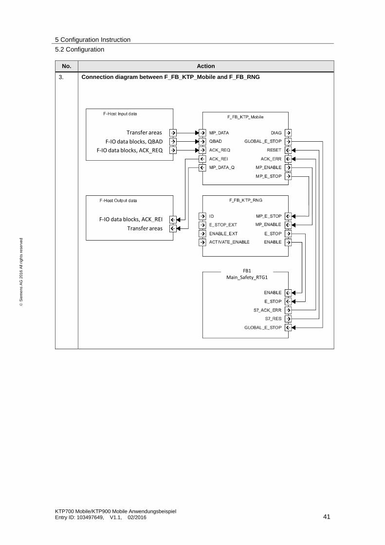
No. Action
3. Connection diagram between F_FB_KTP_Mobile and F_FB_RNG
FB1Main_Safety_RTG1
F-IO data blocks, ACK_REI
F-IO data blocks, QBAD
Transfer areas
F-IO data blocks, ACK_REQ
Transfer areas

5 Configuration Instruction
5.3 HMI configuration
KTP700 Mobile/KTP900 Mobile Anwendungsbeispiel Entry ID: 103497649, V1.1, 02/2016 42
S
iem
en
s A
G 2
01
6 A
ll ri
gh
ts r
ese
rve
d
5.3 HMI configuration
5.3.1 General information
The HMI configuration does not include specifically parameterized functions.
The safety-related functions of the Mobile Panel like
emergency stop/stop button
and the enabling button
are evaluated via the F program.
The following functions have been included in the Mobile Panel configuration.
“Manual mode”
– The operating mode can only be selected via the Mobile Panel with a password protected button.
– The drive can only be activated in “jog mode”.
“Service mode”
– This operating mode is selected with an external key switch. The key switch integrated in the Mobile Panel must not be used for this.
– The drive can only be activated in “jog mode”.

5 Configuration Instruction
5.3 HMI configuration
KTP700 Mobile/KTP900 Mobile Anwendungsbeispiel Entry ID: 103497649, V1.1, 02/2016 43
S
iem
en
s A
G 2
01
6 A
ll ri
gh
ts r
ese
rve
d
5.3.2 Acknowledging using the panel
Table 5-9
No. Description
1. Acknowledging using the panel
In connection with FB187 (F_ACK_OP), the panel can be used for fail-safe acknowledgement.
For this, two buttons are required.
Button 1
– Assign the “SetValue” function to this button under “Events > Press”.
– This tag is from a “Standard DB”. In the example, the “DB100.DBW6” tag is assigned the value “6” via the button.
Button 2
– Assign the “SetValue” function to this button under “Events > Press”.
– This tag is from a “Standard DB”. In the example, the “DB100.DBW6” tag is assigned the value “9” via the button.
Again, please refer to FB21 Link.
The acknowledgement buttons were configured in a “pop-up window”.
5 Configuration Instruction
5.4 Device settings
KTP700 Mobile/KTP900 Mobile Anwendungsbeispiel Entry ID: 103497649, V1.1, 02/2016 44
S
iem
en
s A
G 2
01
6 A
ll ri
gh
ts r
ese
rve
d
5.4 Device settings
General information
The following settings refer to the use of PROFIsafe for the communication between the Mobile Panel and the F-CPU.
5.4.1 Connection box
Connection box ID
The connection box is uniquely identified by the ID preset at the connection box. The ID must be unique throughout the system.
The ID must be identical with the address stored in the Mobile Panel (Link) and the address assigned to the F block “F_FB_KTP_RNG” (Link).
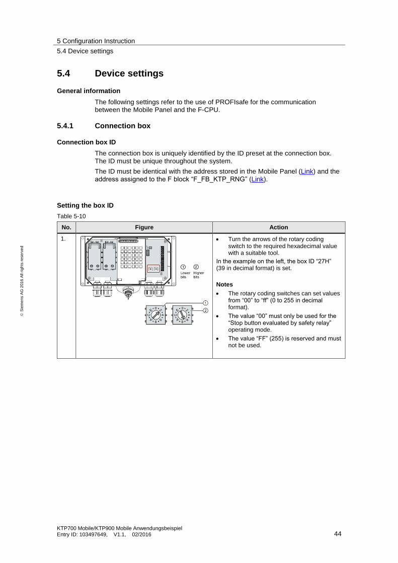
Setting the box ID
Table 5-10
No. Figure Action
1.
Turn the arrows of the rotary coding switch to the required hexadecimal value with a suitable tool.
In the example on the left, the box ID “27H” (39 in decimal format) is set.
Notes
The rotary coding switches can set values from “00” to “ff” (0 to 255 in decimal format).
The value “00” must only be used for the “Stop button evaluated by safety relay” operating mode.
The value “FF” (255) is reserved and must not be used.

5 Configuration Instruction
5.4 Device settings
KTP700 Mobile/KTP900 Mobile Anwendungsbeispiel Entry ID: 103497649, V1.1, 02/2016 45
S
iem
en
s A
G 2
01
6 A
ll ri
gh
ts r
ese
rve
d
5.4.2 Mobile Panel
General information
It is assumed that the Mobile Panel is connected to the connection box and the box ID has been set.
Table 5-11
No. Action
1. Opening the control panel
Open the control panel through the “Start Center” and the “Settings” button.
2. Setting the Ethernet address
Open the “Network and dial-up connections” dialog.
Enter the IP address.
In this example: 172.16.34.210
255.255.0.0
3. Transfer settings
Open the “Transfer” dialog
In “Transfer channel”, select PN/IE.
4. Assign password
Open the “Password” dialog
Assign a password.
The password is required/used for the “Safety Operation” function (Link). In addition, the access to the control panel is protected (Link).
In this example: 100
5. Enter PROFINET name
Open the “PROFINET” dialog.
Activate the “PROFINET IO enabled” checkbox.
Enter the PROFINET name. This must be identical to the name stored in the configuration (Link).
In this example: mobile
6. Enter PROFIsafe address
Open the “PROFIsafe” dialog.
Enter the PROFIsafe address. This must be identical to the address stored in the configuration (Link).
In this example: 1

5 Configuration Instruction
5.4 Device settings
KTP700 Mobile/KTP900 Mobile Anwendungsbeispiel Entry ID: 103497649, V1.1, 02/2016 46
S
iem
en
s A
G 2
01
6 A
ll ri
gh
ts r
ese
rve
d
No. Action
7. Safety Operation
Open the “Safety Operation” dialog.
Select “E-Stop button evaluated by PROFIsafe” from the drop-down list (1).
Enter the connection box ID in the “Decimal field” (in decimal format). The “Hex value” is output automatically. The box ID must be identical to the address stored in the connection box (Link). In this example: 22h (34 decimal)
Confirm the entry with the “Save” button. A password prompt window opens.
Enter the stored password (Link). In this example: 100
When the entered box ID and the password match, this is indicated with a green “check mark”.
Close the window with the “Close” button.
1
5 Configuration Instruction
5.4 Device settings
KTP700 Mobile/KTP900 Mobile Anwendungsbeispiel Entry ID: 103497649, V1.1, 02/2016 47
S
iem
en
s A
G 2
01
6 A
ll ri
gh
ts r
ese
rve
d
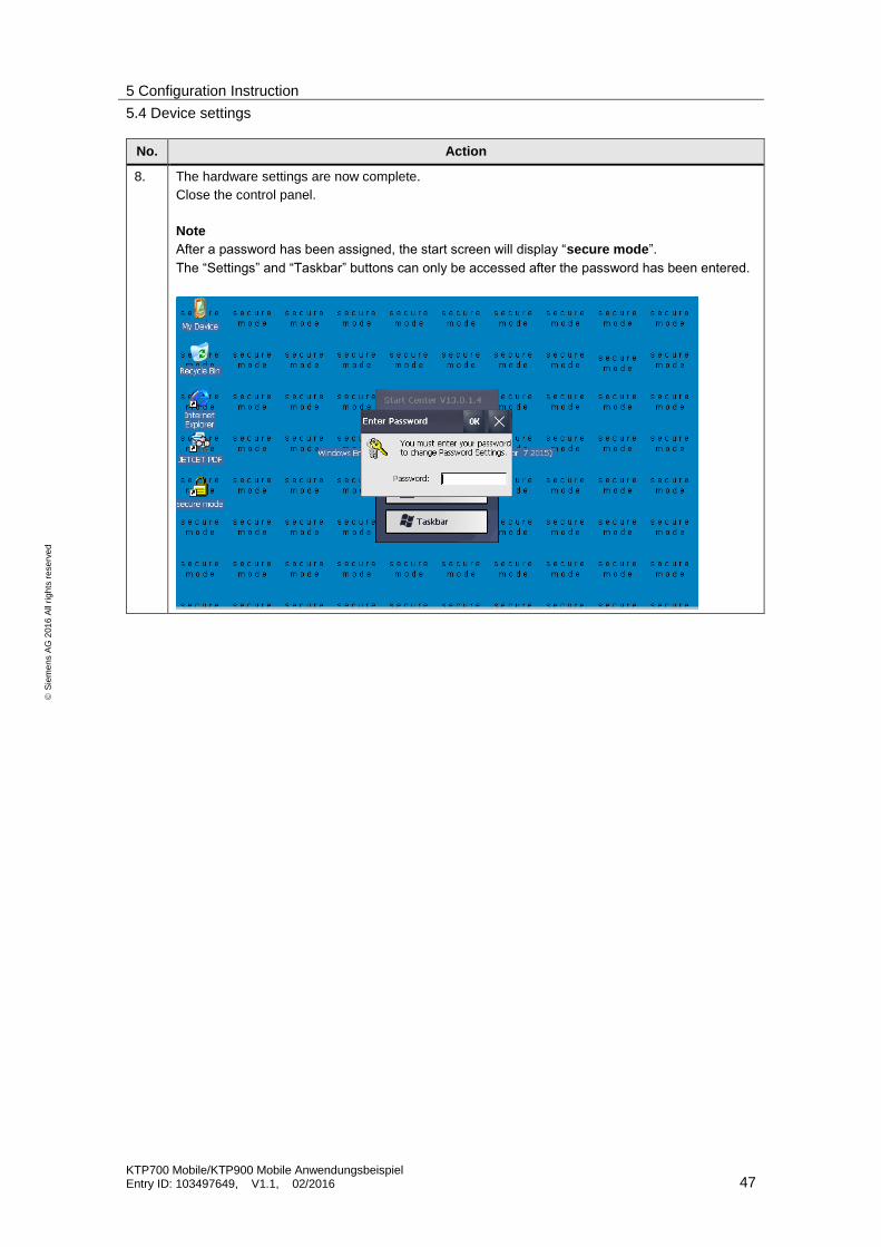
No. Action
8. The hardware settings are now complete.
Close the control panel.
Note
After a password has been assigned, the start screen will display “secure mode”.
The “Settings” and “Taskbar” buttons can only be accessed after the password has been entered.

6 Operating the Application
6.1 General information
KTP700 Mobile/KTP900 Mobile Anwendungsbeispiel Entry ID: 103497649, V1.1, 02/2016 48
S
iem
en
s A
G 2
01
6 A
ll ri
gh
ts r
ese
rve
d
6 Operating the Application
6.1 General information
Screens
The HMI configuration comprises the following screens:
Screen_00_Home (start screen)
Screen_01_Robo1 (robot control)
Screen_02_Settings (panel settings)
Screen_03_AlarmView (Alarm message view)
Screen _04_Diagnostic (Diagnostics view)
Slide-in bars
Slide-in bar on the right (navigation panel)
Slide-in bar at the top (fault message window)
Pop-up screens
Pop-up ACK_HMI
Pop-up alarm
Fault acknowledgment
When there is a fault during operation, e.g. because the emergency stop/stop button was activated at the Mobile Panel, the cause of the fault must be rectified (unlock emergency stop/stop button) and the message must be acknowledged.
Use the “ACK” button or the “Pop-up-ACK_HMI” pop-up screen to acknowledge the fault.
After the CPU voltage supply is switched off and switched back on again, the safety door must be opened completely and closed again (integrated safety function of the door). The, the system must be acknowledged.
A PROFIsafe communication error requires double acknowledgement.
– Fault acknowledgment of PROFIsafe communication.
– Fault acknowledgment of further messages.

6 Operating the Application
6.2 Operating the HMI
KTP700 Mobile/KTP900 Mobile Anwendungsbeispiel Entry ID: 103497649, V1.1, 02/2016 49
S
iem
en
s A
G 2
01
6 A
ll ri
gh
ts r
ese
rve
d
6.2 Operating the HMI
Table 6-1
No. Action Figure
1. Start screen
View of the start screen
2. Slide-in bar on the right
Use this slide-in bar to navigate to the individual panel screens. The bar can be opened from every screen.
3. Slide-in bar at the top
Use this slide-in bar to call the message window. The bar can be opened from every screen.
4. Plant screen
The plant screen is called with the “Application” button.
In this screen the robot is operated.

6 Operating the Application
6.3 Operating modes
KTP700 Mobile/KTP900 Mobile Anwendungsbeispiel Entry ID: 103497649, V1.1, 02/2016 50
S
iem
en
s A
G 2
01
6 A
ll ri
gh
ts r
ese
rve
d
6.3 Operating modes
Basic information
After switching on the control voltage for the system, the safety door must be opened completely and closed again.
When the operating mode is switched during operation, the drive control is interrupted.
When “Service mode” is deactivated, a new operating mode must be selected at the panel.
Automatic mode
Table 6-2
No. Description
1. Selecting automatic mode
Select automatic mode with the “Autom. mode” function button.
This operating mode can only be selected, when “Service mode” is not selected.
2. Drive on/off
The drive is switched on using the “On” function button.
The drive is switched off using the “Off” function button.
When the safety door is opened or an emergency stop is triggered during operation, the drive (-K100) and the safety circuit (-K10 /-K11) are shut down immediately.
Manual mode
Table 6-6
No. Description
1. Selecting manual mode
Select manual mode with the “Manual mode” function button.
This operating mode can only be selected, when “Service mode” is not selected.
This selection is protected with a password. After pressing the function button, the log in dialog box is shown.
User: user
Password: 111
The operating mode can only be selected after entering the correct password.
6 Operating the Application
6.3 Operating modes
KTP700 Mobile/KTP900 Mobile Anwendungsbeispiel Entry ID: 103497649, V1.1, 02/2016 51
S
iem
en
s A
G 2
01
6 A
ll ri
gh
ts r
ese
rve
d
No. Description
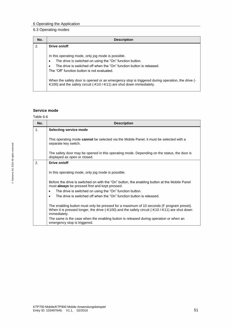
2. Drive on/off
In this operating mode, only jog mode is possible.
The drive is switched on using the “On” function button.
The drive is switched off when the “On” function button is released.
The “Off” function button is not evaluated.
When the safety door is opened or an emergency stop is triggered during operation, the drive (-K100) and the safety circuit (-K10 /-K11) are shut down immediately.
Service mode
Table 6-6
No. Description
1. Selecting service mode
This operating mode cannot be selected via the Mobile Panel; it must be selected with a
separate key switch.
The safety door may be opened in this operating mode. Depending on the status, the door is displayed as open or closed.
2. Drive on/off
In this operating mode, only jog mode is possible.
Before the drive is switched on with the “On” button, the enabling button at the Mobile Panel must always be pressed first and kept pressed.
The drive is switched on using the “On” function button.
The drive is switched off when the “On” function button is released.
The enabling button must only be pressed for a maximum of 10 seconds (F program preset). When it is pressed longer, the drive (-K100) and the safety circuit (-K10 /-K11) are shut down immediately.
The same is the case when the enabling button is released during operation or when an emergency stop is triggered.
7Error detection
KTP700 Mobile/KTP900 Mobile Anwendungsbeispiel Entry ID: 103497649, V1.1, 02/2016 52
S
iem
en
s A
G 2
01
6 A
ll ri
gh
ts r
ese
rve
d
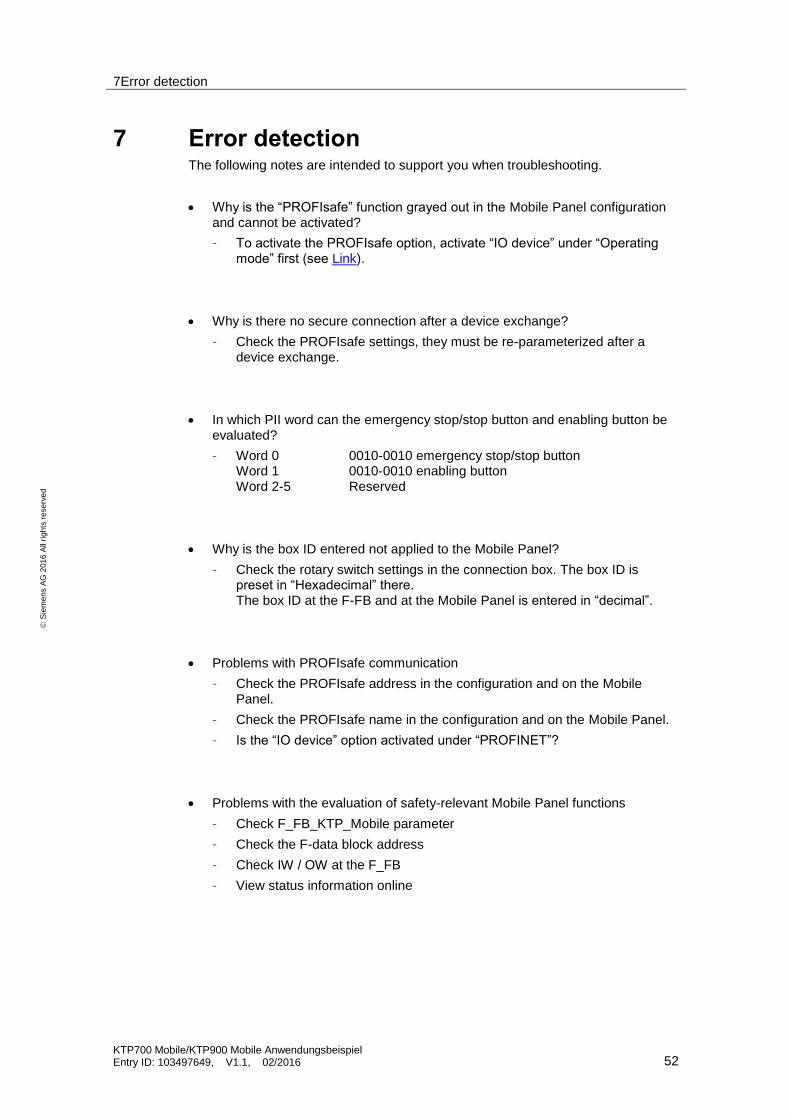
7 Error detection The following notes are intended to support you when troubleshooting.
Why is the “PROFIsafe” function grayed out in the Mobile Panel configuration and cannot be activated?
– To activate the PROFIsafe option, activate “IO device” under “Operating mode” first (see Link).
Why is there no secure connection after a device exchange?
– Check the PROFIsafe settings, they must be re-parameterized after a device exchange.
In which PII word can the emergency stop/stop button and enabling button be evaluated?
– Word 0 0010-0010 emergency stop/stop button Word 1 0010-0010 enabling button Word 2-5 Reserved
Why is the box ID entered not applied to the Mobile Panel?
– Check the rotary switch settings in the connection box. The box ID is preset in “Hexadecimal” there. The box ID at the F-FB and at the Mobile Panel is entered in “decimal”.
Problems with PROFIsafe communication
– Check the PROFIsafe address in the configuration and on the Mobile Panel.
– Check the PROFIsafe name in the configuration and on the Mobile Panel.
– Is the “IO device” option activated under “PROFINET”?
Problems with the evaluation of safety-relevant Mobile Panel functions
– Check F_FB_KTP_Mobile parameter
– Check the F-data block address
– Check IW / OW at the F_FB
– View status information online

7Error detection
KTP700 Mobile/KTP900 Mobile Anwendungsbeispiel Entry ID: 103497649, V1.1, 02/2016 53
S
iem
en
s A
G 2
01
6 A
ll ri
gh
ts r
ese
rve
d
Description of the blocks cannot be found in the online help
– Enter the complete F-FB name as a search term. e.g. F_FB_KTP_Mobile
Why are the I/O addresses of the ET200 SP modules (DI /DO modules) grayed out and cannot be adjusted?
– To change the default addresses of the ET 200SP, the station must be assigned to an IO controller (in this case the F-CPU). Otherwise, the entry field is grayed out.
Why are the robot movements not simulated?
– Check the F-CPU properties under “System and clock memory” and make sure the clock memory option is enabled and the correct byte is used.
How can I set the box IDs of several connection boxes at the Mobile Panel?
– Always use the same menu. Go to each connection box and plug in the Mobile Panel. Open the “Safety Operation” menu and enter the corresponding box ID.
Is it possible to activate the PROFIsafe connection via a system function at the Mobile Panel after the PROFIsafe connection was deactivated with the system function “PROFIsafeDisconnect”?
– No. To activate the PROFIsafe connection, you must restart the panel runtime.
Why does the drive shut down when I remove the Mobile Panel from the connection box?
– Make sure to disconnect the PROFIsafe connection before unplugging the panel. Use the system function “PROFIsafeDisconnect” to do this; you can configure it in a button, for example. Alternatively, terminate the Mobile Panel runtime and confirm the PROFIsafe disconnection in the logoff dialog.

8 Links & Literature
KTP700 Mobile/KTP900 Mobile Anwendungsbeispiel Entry ID: 103497649, V1.1, 02/2016 54
S
iem
en
s A
G 2
01
6 A
ll ri
gh
ts r
ese
rve
d
8 Links & Literature Table 8-1
Topic Title
\1\ Siemens Industry Online Support
https://support.industry.siemens.com
\2\ Download page of the entry
https://support.industry.siemens.com/cs/ww/de/view/103497649https://support.industry.siemens.com/cs/ww/en/view/103497649
\3\ Manual Overview of various manuals on the Mobile Panel
https://support.industry.siemens.com/cs/ww/en/ps/14746/man
\4\ Manual SIMATIC Distributed I/O System Fail-Safe Engineering ET 200SP Distributed I/O System
http://support.automation.siemens.com/WW/view/en/12490437
\5\ Manual SIMATIC Industrial Software SIMATIC Safety - Configuring and Programming
https://support.industry.siemens.com/cs/ww/en/view/54110126
\6\ Manual SIMATIC Industrial Software SIMATIC Safety V13 - Getting Started
https://support.industry.siemens.com/cs/ww/en/view/101177693
9 History
Table 9-1
Version Date Modifications
V1.0 06/2014 First version
V1.1 02/2016 S7 Distributed Safety -> STEP 7 Safety Advanced