Embed Size (px)
Citation preview
Stand 12/2002
COMBIVERT F4-F
APPLICATION MANUAL
Art.Nr.: 00.F4.FEA-K300
Charge 40,- Euro

1 1Name: Basis
KEB COMBIVERT F4-F2 18.12.02
Introduction General
© KEB Antriebstechnik, 2002All Rights reserved
Chapter Section Page Date
31 1 318.12.02KEB COMBIVERT F4-F
Name: Basis
1
IntroductionGeneral
© KEB Antriebstechnik, 2002All Rights reserved
Chapter Section PageDate
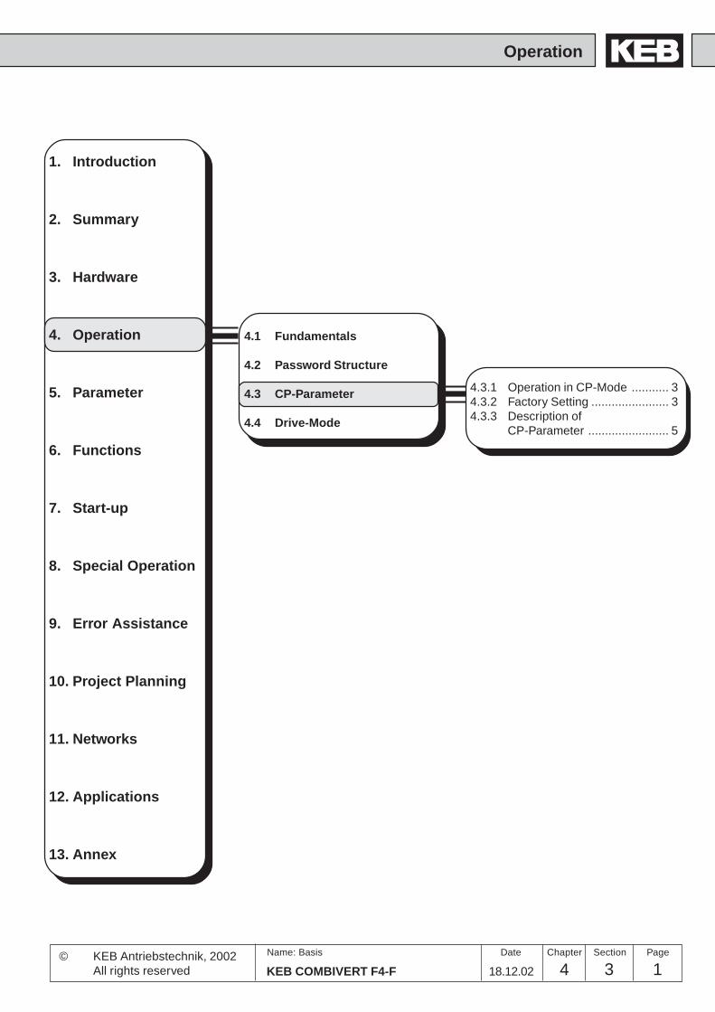
This chapter shall allow a fast access to the wanted information. It consists of contents,index and search criterion.
Here the inverter and its features as well as the operating conditions and applicationpurpose are described.
Description of hardware, technical data of the inverter as well as connection of powerand control terminals.
The basic operation of the KEB COMBIVERT like password input, parameter and setselection.
A list of all parameters classified according to parameter groups. The parameterdescription comprises addresses, value ranges and references with regard to thefunctions for which they are used.
To make the programming easier all inverter functions and the parameters belongingto it are comprised in this chapter.
Gives support with regard to the initial start-up and shows possibilities and techniquesfor the optimization of the drive.
Describes special operating modes, like e.g. DC-coupling.
Avoidance of errors, evaluation of error messages and elimination of the causes.
Survey of the possible interconnection in existing networks; address and value tablefor the implementation in own protocols.
Survey of the possible interconnection of the KEB COMBIVET in existing networks.
In this chapter you find descriptions of some applications which may give new impulsesor help to solve own applications.
Everything that didn’t fit anywhere else or what we didn’t think of earlier.
1. Introduction
2. Summary
3. Hardware
4. Operation
5. Parameter
6. Functions
7. Start-up
8. Special Operation
9. Error Assistance
10. Project Planning
11. Networks
12. Applications
13. Annex

1 1Name: Basis
KEB COMBIVERT F4-F4 18.12.02
Introduction
© KEB Antriebstechnik, 2002All Rights reserved
Chapter Section Page Date

51 1 518.12.02KEB COMBIVERT F4-F
Name: Basis
1. Introduction
2. Summary
3. Hardware
4. Operation
5. Parameter
6. Functions
7. Start-up
8. Special Operation
9. Error Assistance
10. Project Planning
11. Networks
12. Applications
13. Annex
1.1 General
Introduction
© KEB Antriebstechnik, 2002All Rights reserved
Chapter Section PageDate
1.1.1 Table of Contents ................... 71.1.2 Preface ................................... 71.1.3 Record of Changes ................ 91.1.4 Technical Terms ................... 131.1.5 Characters and Symbols ...... 15

1 1Name: Basis
KEB COMBIVERT F4-F6 18.12.02
Introduction General
© KEB Antriebstechnik, 2002All Rights reserved
Chapter Section Page Date
71 1 718.12.02KEB COMBIVERT F4-F
Name: Basis
1
IntroductionGeneral
© KEB Antriebstechnik, 2002All Rights reserved
Chapter Section PageDate
1.1 General1. Introduction
1.1.1 Table of Contents
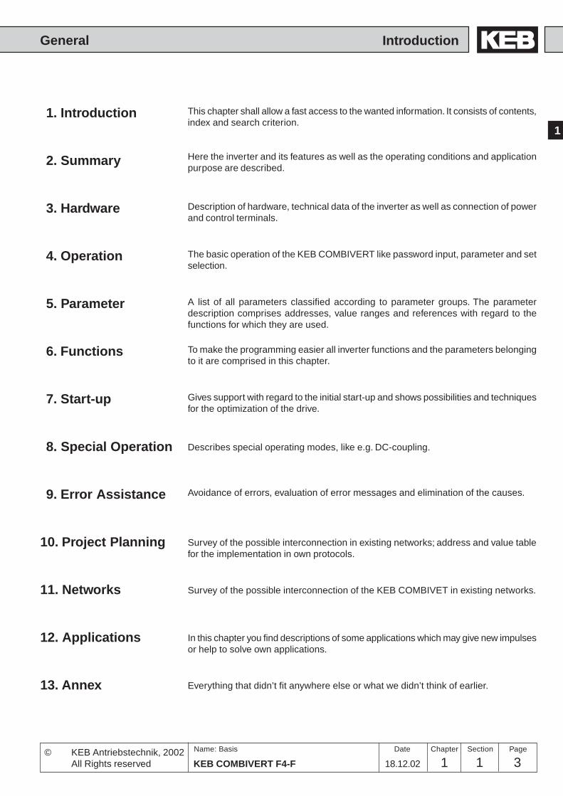
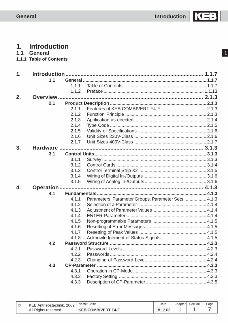
1. Introduction ............................................................................................ 1.1.71.1 General ................................................................................................ 1.1.7
1.1.1 Table of Contents ................................................................ 1.1.71.1.2 Preface .............................................................................. 1.1.13
2. Overview ................................................................................................. 2.1.32.1 Product Description ........................................................................... 2.1.3
2.1.1 Features of KEB COMBIVERT F4-F ................................... 2.1.32.1.2 Function Principle ............................................................... 2.1.32.1.3 Application as directed ........................................................ 2.1.42.1.4 Type Code ........................................................................... 2.1.52.1.5 Validity of Specifications ..................................................... 2.1.62.1.6 Unit Sizes 230V-Class ........................................................ 2.1.62.1.7 Unit Sizes 400V-Class ........................................................ 2.1.7
3. Hardware ................................................................................................ 3.1.33.1 Control Units....................................................................................... 3.1.3
3.1.1 Survey ................................................................................. 3.1.33.1.2 Control Cards ...................................................................... 3.1.43.1.3 Control Terminal Strip X2..................................................... 3.1.53.1.4 Wiring of Digital In-/Outputs ................................................. 3.1.63.1.5 Wiring of Analog In-/Outputs ................................................ 3.1.6
4. Operation ................................................................................................ 4.1.34.1 Fundamentals ..................................................................................... 4.1.3
4.1.1 Parameters, Parameter Groups, Parameter Sets ................. 4.1.34.1.2 Selection of a Parameter ..................................................... 4.1.44.1.3 Adjustment of Parameter Values.......................................... 4.1.44.1.4 ENTER-Parameter .............................................................. 4.1.44.1.5 Non-programmable Parameters .......................................... 4.1.54.1.6 Resetting of Error Messages ............................................... 4.1.54.1.7 Resetting of Peak Values..................................................... 4.1.54.1.8 Acknowledgement of Status Signals ................................... 4.1.5
4.2 Password Structure ........................................................................... 4.2.34.2.1 Password Levels ................................................................. 4.2.34.2.2 Passwords ........................................................................... 4.2.44.2.3 Changing of Password Level ............................................... 4.2.4
4.3 CP-Parameter ..................................................................................... 4.3.34.3.1 Operation in CP-Mode......................................................... 4.3.34.3.2 Factory Setting .................................................................... 4.3.34.3.3 Description of CP-Parameter ............................................... 4.3.5
1 1Name: Basis
KEB COMBIVERT F4-F8 18.12.02
Introduction General
© KEB Antriebstechnik, 2002All Rights reserved
Chapter Section Page Date
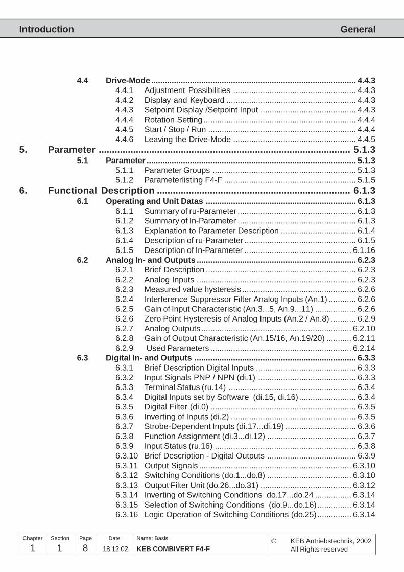
4.4 Drive-Mode .......................................................................................... 4.4.34.4.1 Adjustment Possibilities ...................................................... 4.4.34.4.2 Display and Keyboard ......................................................... 4.4.34.4.3 Setpoint Display /Setpoint Input .......................................... 4.4.34.4.4 Rotation Setting ................................................................... 4.4.44.4.5 Start / Stop / Run ................................................................. 4.4.44.4.6 Leaving the Drive-Mode ...................................................... 4.4.5
5. Parameter ............................................................................................... 5.1.35.1 Parameter ............................................................................................ 5.1.3
5.1.1 Parameter Groups ............................................................... 5.1.35.1.2 Parameterlisting F4-F .......................................................... 5.1.5
6. Functional Description ......................................................................... 6.1.36.1 Operating and Unit Datas .................................................................. 6.1.3
6.1.1 Summary of ru-Parameter .................................................... 6.1.36.1.2 Summary of In-Parameter .................................................... 6.1.36.1.3 Explanation to Parameter Description ................................. 6.1.46.1.4 Description of ru-Parameter ................................................. 6.1.56.1.5 Description of In-Parameter ............................................... 6.1.16
6.2 Analog In- and Outputs ...................................................................... 6.2.36.2.1 Brief Description .................................................................. 6.2.36.2.2 Analog Inputs ...................................................................... 6.2.36.2.3 Measured value hysteresis .................................................. 6.2.66.2.4 Interference Suppressor Filter Analog Inputs (An.1) ............ 6.2.66.2.5 Gain of Input Characteristic (An.3...5, An.9...11) .................. 6.2.66.2.6 Zero Point Hysteresis of Analog Inputs (An.2 / An.8) ........... 6.2.96.2.7 Analog Outputs .................................................................. 6.2.106.2.8 Gain of Output Characteristic (An.15/16, An.19/20) ........... 6.2.116.2.9 Used Parameters .............................................................. 6.2.14
6.3 Digital In- and Outputs ....................................................................... 6.3.36.3.1 Brief Description Digital Inputs ............................................ 6.3.36.3.2 Input Signals PNP / NPN (di.1) ........................................... 6.3.36.3.3 Terminal Status (ru.14) ........................................................ 6.3.46.3.4 Digital Inputs set by Software (di.15, di.16) ......................... 6.3.46.3.5 Digital Filter (di.0) ................................................................ 6.3.56.3.6 Inverting of Inputs (di.2) ....................................................... 6.3.56.3.7 Strobe-Dependent Inputs (di.17...di.19) ............................... 6.3.66.3.8 Function Assignment (di.3...di.12) ....................................... 6.3.76.3.9 Input Status (ru.16) .............................................................. 6.3.86.3.10 Brief Description - Digital Outputs ....................................... 6.3.96.3.11 Output Signals ................................................................... 6.3.106.3.12 Switching Conditions (do.1...do.8) ..................................... 6.3.106.3.13 Output Filter Unit (do.26...do.31) ........................................ 6.3.126.3.14 Inverting of Switching Conditions do.17...do.24 ................ 6.3.146.3.15 Selection of Switching Conditions (do.9...do.16)............... 6.3.146.3.16 Logic Operation of Switching Conditions (do.25)............... 6.3.14
91 1 918.12.02KEB COMBIVERT F4-F
Name: Basis
1
IntroductionGeneral
© KEB Antriebstechnik, 2002All Rights reserved
Chapter Section PageDate
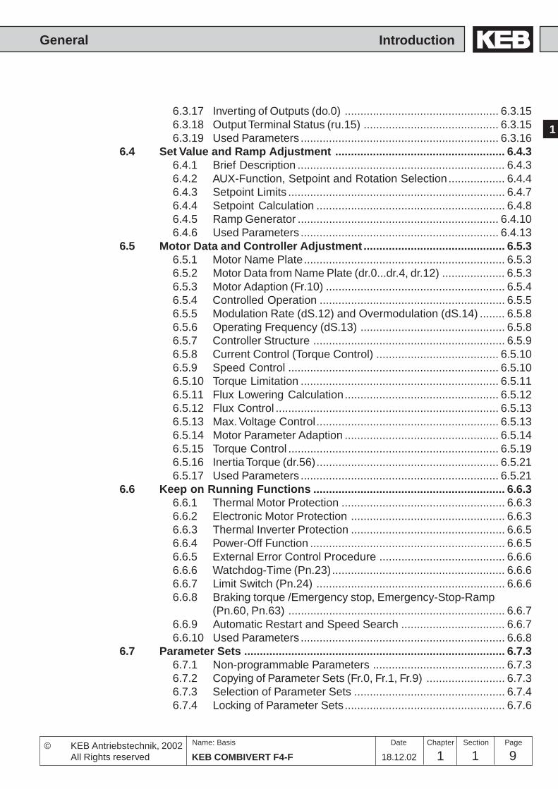
6.3.17 Inverting of Outputs (do.0) ................................................. 6.3.156.3.18 Output Terminal Status (ru.15) ........................................... 6.3.156.3.19 Used Parameters ............................................................... 6.3.16
6.4 Set Value and Ramp Adjustment ...................................................... 6.4.36.4.1 Brief Description .................................................................. 6.4.36.4.2 AUX-Function, Setpoint and Rotation Selection .................. 6.4.46.4.3 Setpoint Limits ..................................................................... 6.4.76.4.4 Setpoint Calculation ............................................................ 6.4.86.4.5 Ramp Generator ................................................................ 6.4.106.4.6 Used Parameters ............................................................... 6.4.13
6.5 Motor Data and Controller Adjustment ............................................. 6.5.36.5.1 Motor Name Plate................................................................ 6.5.36.5.2 Motor Data from Name Plate (dr.0...dr.4, dr.12) .................... 6.5.36.5.3 Motor Adaption (Fr.10) ......................................................... 6.5.46.5.4 Controlled Operation ........................................................... 6.5.56.5.5 Modulation Rate (dS.12) and Overmodulation (dS.14) ........ 6.5.86.5.6 Operating Frequency (dS.13) .............................................. 6.5.86.5.7 Controller Structure ............................................................. 6.5.96.5.8 Current Control (Torque Control) ....................................... 6.5.106.5.9 Speed Control ................................................................... 6.5.106.5.10 Torque Limitation ............................................................... 6.5.116.5.11 Flux Lowering Calculation................................................. 6.5.126.5.12 Flux Control ....................................................................... 6.5.136.5.13 Max. Voltage Control.......................................................... 6.5.136.5.14 Motor Parameter Adaption ................................................. 6.5.146.5.15 Torque Control ................................................................... 6.5.196.5.16 Inertia Torque (dr.56).......................................................... 6.5.216.5.17 Used Parameters ............................................................... 6.5.21
6.6 Keep on Running Functions ............................................................. 6.6.36.6.1 Thermal Motor Protection .................................................... 6.6.36.6.2 Electronic Motor Protection ................................................. 6.6.36.6.3 Thermal Inverter Protection ................................................. 6.6.56.6.4 Power-Off Function .............................................................. 6.6.56.6.5 External Error Control Procedure ........................................ 6.6.66.6.6 Watchdog-Time (Pn.23)....................................................... 6.6.66.6.7 Limit Switch (Pn.24) ............................................................ 6.6.66.6.8 Braking torque /Emergency stop, Emergency-Stop-Ramp
(Pn.60, Pn.63) ..................................................................... 6.6.76.6.9 Automatic Restart and Speed Search ................................. 6.6.76.6.10 Used Parameters ................................................................. 6.6.8
6.7 Parameter Sets ................................................................................... 6.7.36.7.1 Non-programmable Parameters .......................................... 6.7.36.7.2 Copying of Parameter Sets (Fr.0, Fr.1, Fr.9) ......................... 6.7.36.7.3 Selection of Parameter Sets ................................................ 6.7.46.7.4 Locking of Parameter Sets................................................... 6.7.6
1 1Name: Basis
KEB COMBIVERT F4-F10 18.12.02
Introduction General
© KEB Antriebstechnik, 2002All Rights reserved
Chapter Section Page Date
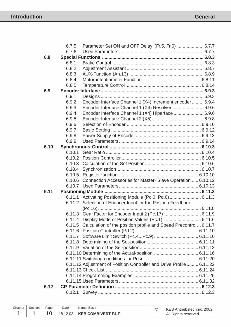
6.7.5 Parameter Set ON and OFF Delay (Fr.5, Fr.6) ..................... 6.7.76.7.6 Used Parameters ................................................................. 6.7.7
6.8 Special Functions .............................................................................. 6.8.36.8.1 Brake Control ...................................................................... 6.8.36.8.2 Adjustment Assistant ........................................................... 6.8.76.8.3 AUX-Function (An.13) ......................................................... 6.8.96.8.4 Motorpotentiometer Function ............................................. 6.8.116.8.5 Temperature Control .......................................................... 6.8.14
6.9 Encoder Interface ............................................................................... 6.9.36.9.1 Designs ............................................................................... 6.9.36.9.2 Encoder Interface Channel 1 (X4) Increment encoder ......... 6.9.46.9.3 Encoder Interface Channel 1 (X4) Resolver ........................ 6.9.66.9.4 Encoder Interface Channel 1 (X4) Hiperface ....................... 6.9.66.9.5 Encoder Interface Channel 2 (X5) ....................................... 6.9.86.9.6 Selection of Encoder ......................................................... 6.9.106.9.7 Basic Setting ..................................................................... 6.9.126.9.8 Power Supply of Encoder .................................................. 6.9.136.9.9 Used Parameters ............................................................... 6.9.14
6.10 Synchronous Control ...................................................................... 6.10.36.10.1 Gear Ratio ......................................................................... 6.10.46.10.2 Position Controller ............................................................. 6.10.56.10.3 Calculation of the Set Position........................................... 6.10.66.10.4 Synchronization ................................................................ 6.10.76.10.5 Register function ............................................................. 6.10.106.10.6 Connection Accessories for Master- Slave Operation ..... 6.10.126.10.7 Used Parameters ............................................................. 6.10.13
6.11 Positioning Module .......................................................................... 6.11.36.11.1 Activating Positioning Module (Pc.0, Pd.0) ........................ 6.11.36.11.2 Selection of Endocer Input for the Position Feedback
(Pc.16) ............................................................................... 6.11.86.11.3 Gear Factor for Encoder Input 2 (Pc.17) ............................ 6.11.96.11.4 Display Mode of Position Values (Pc.1) ............................. 6.11.66.11.5 Calculation of the position profile and Speed Precontrol ... 6.11.76.11.6 Position Controller (Pd.2) ................................................ 6.11.106.11.7 Software Limit Switch (Pc.4...Pc.9) .................................. 6.11.106.11.8 Determining of the Set-position ....................................... 6.11.116.11.9 Variation of the Set-position............................................. 6.11.136.11.10 Determining of the Actual-position .................................. 6.11.166.11.11 Switching conditions for Posi ........................................... 6.11.206.11.12 Adjustment of Position Controller and Drive Profile ......... 6.11.226.11.13 Check List ....................................................................... 6.11.246.11.14 Programming Examples .................................................. 6.11.256.11.15 Used Parameters ............................................................. 6.11.32
6.12 CP-Parameter Definition .................................................................. 6.12.36.12.1 Survey ............................................................................... 6.12.3
111 1 1118.12.02KEB COMBIVERT F4-F
Name: Basis
1
IntroductionGeneral
© KEB Antriebstechnik, 2002All Rights reserved
Chapter Section PageDate
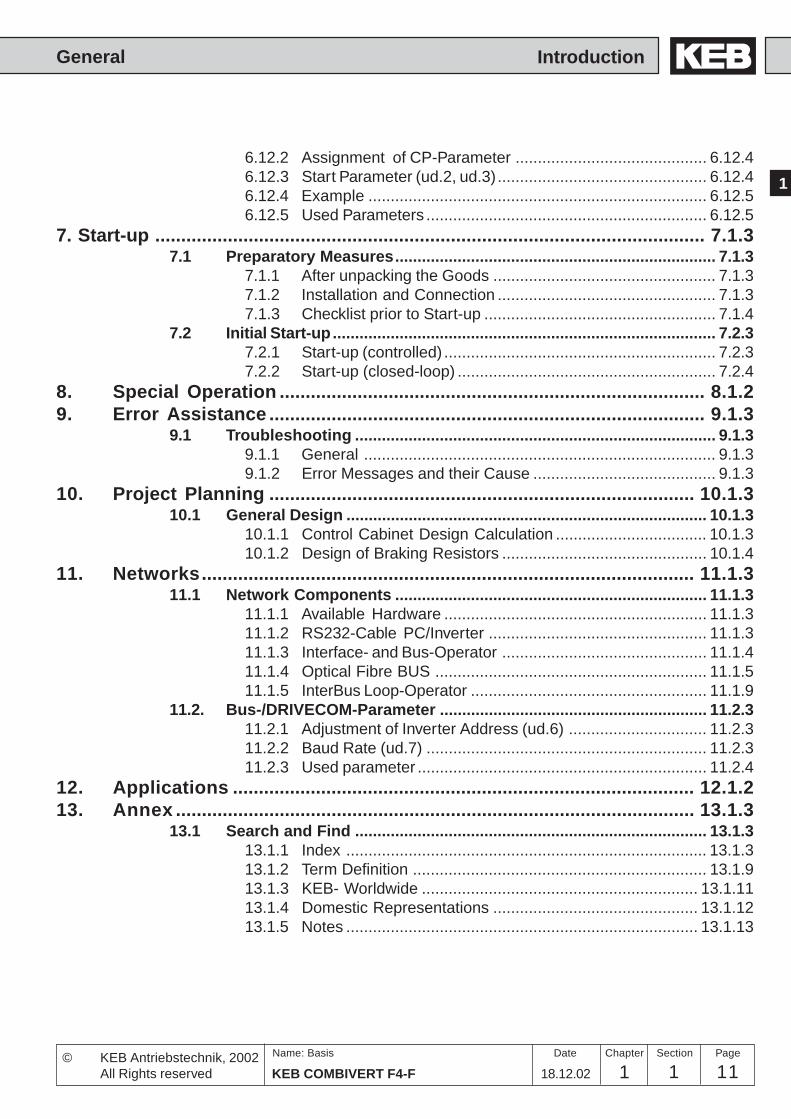
6.12.2 Assignment of CP-Parameter ........................................... 6.12.46.12.3 Start Parameter (ud.2, ud.3)............................................... 6.12.46.12.4 Example ............................................................................ 6.12.56.12.5 Used Parameters ............................................................... 6.12.5
7. Start-up .......................................................................................................... 7.1.37.1 Preparatory Measures........................................................................ 7.1.3
7.1.1 After unpacking the Goods .................................................. 7.1.37.1.2 Installation and Connection ................................................. 7.1.37.1.3 Checklist prior to Start-up .................................................... 7.1.4
7.2 Initial Start-up...................................................................................... 7.2.37.2.1 Start-up (controlled) ............................................................. 7.2.37.2.2 Start-up (closed-loop) .......................................................... 7.2.4
8. Special Operation .................................................................................. 8.1.29. Error Assistance .................................................................................... 9.1.3
9.1 Troubleshooting ................................................................................. 9.1.39.1.1 General ............................................................................... 9.1.39.1.2 Error Messages and their Cause ......................................... 9.1.3
10. Project Planning .................................................................................. 10.1.310.1 General Design ................................................................................. 10.1.3
10.1.1 Control Cabinet Design Calculation .................................. 10.1.310.1.2 Design of Braking Resistors .............................................. 10.1.4
11. Networks............................................................................................... 11.1.311.1 Network Components ...................................................................... 11.1.3
11.1.1 Available Hardware ........................................................... 11.1.311.1.2 RS232-Cable PC/Inverter ................................................. 11.1.311.1.3 Interface- and Bus-Operator .............................................. 11.1.411.1.4 Optical Fibre BUS ............................................................. 11.1.511.1.5 InterBus Loop-Operator ..................................................... 11.1.9
11.2. Bus-/DRIVECOM-Parameter ............................................................ 11.2.311.2.1 Adjustment of Inverter Address (ud.6) ............................... 11.2.311.2.2 Baud Rate (ud.7) ............................................................... 11.2.311.2.3 Used parameter ................................................................. 11.2.4
12. Applications ......................................................................................... 12.1.213. Annex .................................................................................................... 13.1.3
13.1 Search and Find ............................................................................... 13.1.313.1.1 Index ................................................................................. 13.1.313.1.2 Term Definition .................................................................. 13.1.913.1.3 KEB- Worldwide .............................................................. 13.1.1113.1.4 Domestic Representations .............................................. 13.1.1213.1.5 Notes ............................................................................... 13.1.13

1 1Name: Basis
KEB COMBIVERT F4-F12 18.12.02
Introduction General
© KEB Antriebstechnik, 2002All Rights reserved
Chapter Section Page Date
131 1 1318.12.02KEB COMBIVERT F4-F
Name: Basis
1
IntroductionGeneral
© KEB Antriebstechnik, 2002All Rights reserved
Chapter Section PageDate
Who shall read all this?Everybody who is entrusted with the development and construction of applications.He who knows the extensive programming possibilities of the COMBIVERT, cansave external controls and expensive cabling already in the planning stage of amachine simply by using the unit as active control element. This manual is not areplacement of the documentation accompanying the unit, it serves only ascompletion.
1000 and one application...and if possible with one unit. Who does not know this demand from purchasingdepartments, production or service. We have taken this request very seriouslyand developed a series with open programming, which can be adapted to thedifferent applications with PC, chipcard or manually.
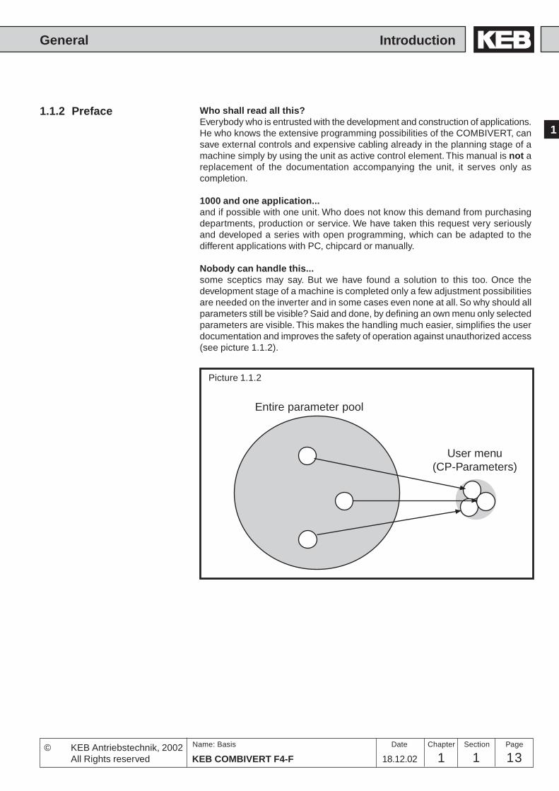
Nobody can handle this...some sceptics may say. But we have found a solution to this too. Once thedevelopment stage of a machine is completed only a few adjustment possibilitiesare needed on the inverter and in some cases even none at all. So why should allparameters still be visible? Said and done, by defining an own menu only selectedparameters are visible. This makes the handling much easier, simplifies the userdocumentation and improves the safety of operation against unauthorized access(see picture 1.1.2).
1.1.2 Preface
Picture 1.1.2
Entire parameter pool
User menu(CP-Parameters)

1 1Name: Basis
KEB COMBIVERT F4-F14 18.12.02
Introduction
© KEB Antriebstechnik, 2002All Rights reserved
Chapter Section Page Date
© KEB Antriebstechnik, 2002All Rights reserved
Chapter Section PageDate
2 1 1KEB COMBIVERT F4-F
Name: Basis
15.10.02
1. Introduction
2. Summary
3. Hardware
4. Operation
5. Parameter
6. Functions
7. Start-up
8. Special Operation
9. Error Assistance
10. Project Planning
11. Networks
12. Applications
13. Annex
2.1 Product Description
Summary
2.1.1 Features of KEB COMBIVERTF4-F ....................................... 3
2.1.2 Function Principle................... 42.1.3 Application as directed ........... 42.1.4 Type Code .............................. 52.1.5 Validity of Specifications ......... 62.1.6 Unit Sizes 230V-Class ............ 62.1.7 Unit Sizes 400V-Class ............ 7

© KEB Antriebstechnik, 2002All rights reserved
Chapter Section Page Date
2 1 KEB COMBIVERT F4-F2Name: Basis
15.10.02
Product DescriptionSummary
2
© KEB Antriebstechnik, 2002All Rights reserved
Chapter Section PageDate
2 1 3KEB COMBIVERT F4-F
Name: Basis
15.10.02
Product Description Summary
=
~ =
~
UN R
CW
U
VUZK
L1
L2
(L3)
M3 ~
2.1.1 Features of KEBCOMBIVERT F4-F
2.1 Product Description
KEBCOMBIVERT
F4-F
8 parameter sets
17 parameter groups
Prog. Operator menu
1 prog. relay output
7 prog. digital inputs
2 prog. digital outputs
2 prog. analog outputs
2 prog. analog inputsHardware current limit
Jogging-function (prog.)
Protective equipment
Prog. filter for analog and digital inputs
Software In-/Outputs
Adjustable balancing of the ramps
Hour meter
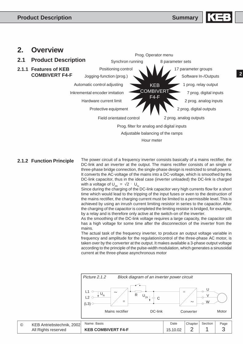
2.1.2 Function Principle The power circuit of a frequency inverter consists basically of a mains rectifier, theDC-link and an inverter at the output. The mains rectifier consists of an single orthree-phase bridge connection, the single-phase design is restricted to small powers.It converts the AC-voltage of the mains into a DC-voltage, which is smoothed by theDC-link capacitor, thus in the ideal case (inverter unloaded) the DC-link is chargedwith a voltage of U
ZK = √2 . U
N.
Since during the charging of the DC-link capacitor very high currents flow for a shorttime which would lead to the tripping of the input fuses or even to the destruction ofthe mains rectifier, the charging current must be limited to a permissible level. This isachieved by using an inrush current limiting resistor in series to the capacitor. Afterthe charging of the capacitor is completed the limiting resistor is bridged, for example,by a relay and is therefore only active at the switch-on of the inverter.As the smoothing of the DC-link voltage requires a large capacity, the capacitor stillhas a high voltage for some time after the disconnection of the inverter from themains.The actual task of the frequency inverter, to produce an output voltage variable infrequency and amplitude for the regulation/control of the three-phase AC motor, istaken over by the converter at the output. It makes available a 3-phase output voltageaccording to the principle of the pulse-width modulation, which generates a sinusoidalcurrent at the three-phase asynchronous motor
Mains rectifier MotorConverterDC-link
Picture 2.1.2 Block diagram of an inverter power circuit
2. Overview
Inkremental encoder imitation
Positioning control
Field orientated control
Synchron running
Automatic control adjusting
© KEB Antriebstechnik, 2002All rights reserved
Chapter Section Page Date
2 1 KEB COMBIVERT F4-F4Name: Basis
15.10.02
Product DescriptionSummary
2.1.3 Application as directed
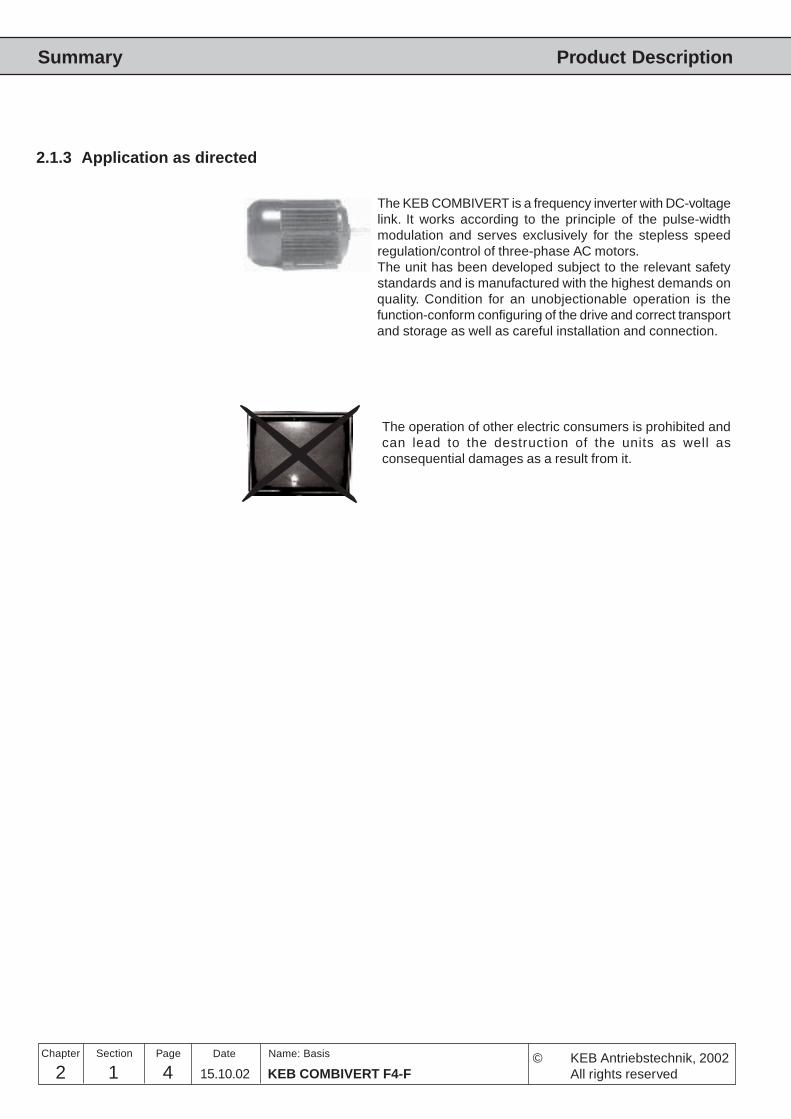
The KEB COMBIVERT is a frequency inverter with DC-voltagelink. It works according to the principle of the pulse-widthmodulation and serves exclusively for the stepless speedregulation/control of three-phase AC motors.The unit has been developed subject to the relevant safetystandards and is manufactured with the highest demands onquality. Condition for an unobjectionable operation is thefunction-conform configuring of the drive and correct transportand storage as well as careful installation and connection.
The operation of other electric consumers is prohibited andcan lead to the destruction of the units as well asconsequential damages as a result from it.
2
© KEB Antriebstechnik, 2002All Rights reserved
Chapter Section PageDate
2 1 5KEB COMBIVERT F4-F
Name: Basis
15.10.02
Product Description Summary
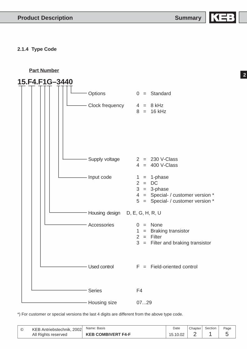
2.1.4 Type Code
Options 0 = Standard
Clock frequency 4 = 8 kHz8 = 16 kHz
Supply voltage 2 = 230 V-Class4 = 400 V-Class
Input code 1 = 1-phase2 = DC3 = 3-phase4 = Special- / customer version *5 = Special- / customer version *
Housing design D, E, G, H, R, U
Accessories 0 = None1 = Braking transistor2 = Filter3 = Filter and braking transistor
Used control F = Field-oriented control
Series F4
Housing size 07...29
Part Number
*) For customer or special versions the last 4 digits are different from the above type code.
15.F4.F1G–3440
© KEB Antriebstechnik, 2002All rights reserved
Chapter Section Page Date
2 1 KEB COMBIVERT F4-F6Name: Basis
15.10.02
Product DescriptionSummary
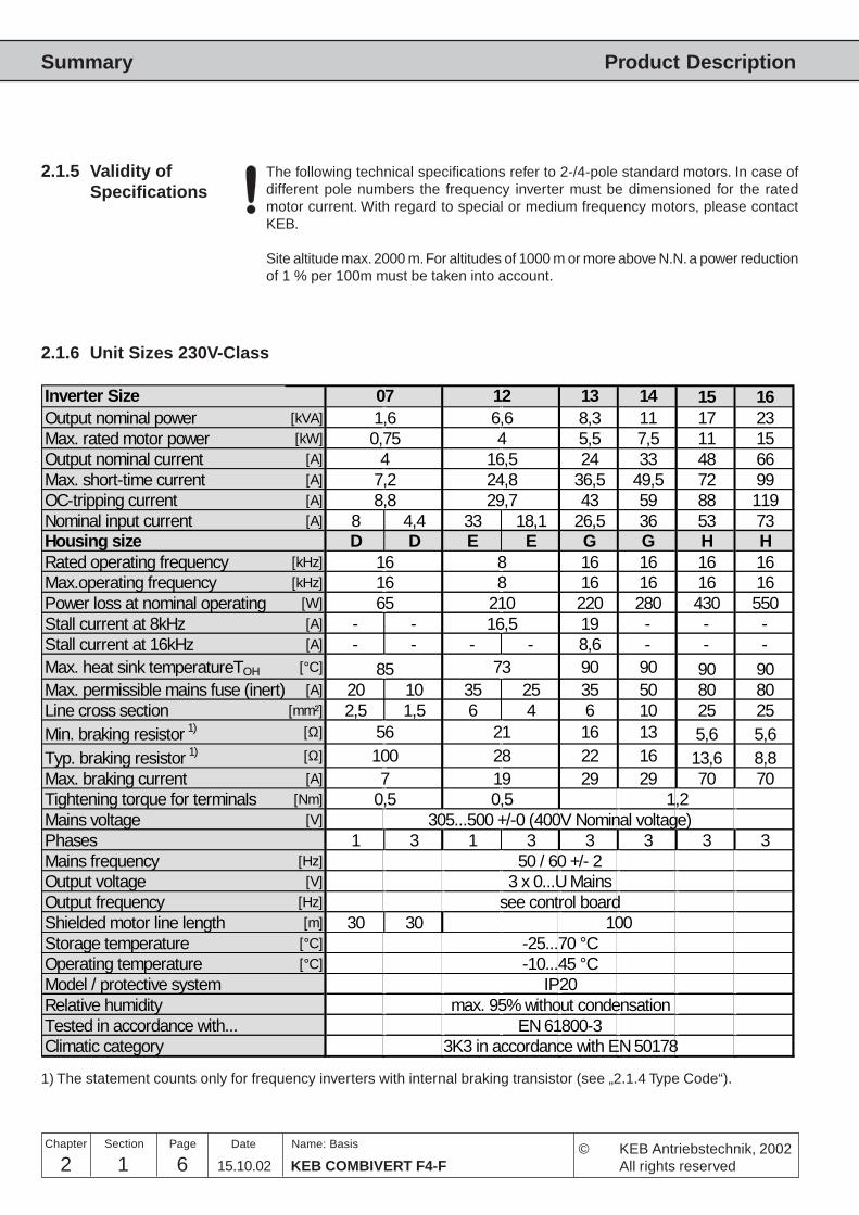
The following technical specifications refer to 2-/4-pole standard motors. In case ofdifferent pole numbers the frequency inverter must be dimensioned for the ratedmotor current. With regard to special or medium frequency motors, please contactKEB.
Site altitude max. 2000 m. For altitudes of 1000 m or more above N.N. a power reductionof 1 % per 100m must be taken into account.
1) The statement counts only for frequency inverters with internal braking transistor (see „2.1.4 Type Code“).
Inverter Size 07 12 13 14 15 16Output nominal power [kVA] 1,6 6,6 8,3 11 17 23Max. rated motor power [kW] 0,75 4 5,5 7,5 11 15Output nominal current [A] 4 16,5 24 33 48 66Max. short-time current [A] 7,2 24,8 36,5 49,5 72 99OC-tripping current [A] 8,8 29,7 43 59 88 119Nominal input current [A] 8 4,4 33 18,1 26,5 36 53 73Housing size D D E E G G H HRated operating frequency [kHz] 16 8 16 16 16 16Max.operating frequency [kHz] 16 8 16 16 16 16Power loss at nominal operating [W] 65 210 220 280 430 550Stall current at 8kHz [A] - - 16,5 19 - - -Stall current at 16kHz [A] - - - - 8,6 - - -Max. heat sink temperatureTOH [°C] 85 73 90 90 90 90Max. permissible mains fuse (inert) [A] 20 10 35 25 35 50 80 80Line cross section [mm²] 2,5 1,5 6 4 6 10 25 25Min. braking resistor 1) [Ω] 56 21 16 13 5,6 5,6Typ. braking resistor 1) [Ω] 100 28 22 16 13,6 8,8Max. braking current [A] 7 19 29 29 70 70Tightening torque for terminals [Nm] 0,5 0,5 1,2Mains voltage [V] 305...500 +/-0 (400V Nominal voltage)Phases 1 3 1 3 3 3 3 3Mains frequency [Hz] 50 / 60 +/- 2Output voltage [V] 3 x 0...U MainsOutput frequency [Hz] see control boardShielded motor line length [m] 30 30 100Storage temperature [°C] -25...70 °COperating temperature [°C] -10...45 °CModel / protective system IP20Relative humidity max. 95% without condensationTested in accordance with... EN 61800-3Climatic category 3K3 in accordance with EN 50178
2.1.5 Validity ofSpecifications
2.1.6 Unit Sizes 230V-Class
2
© KEB Antriebstechnik, 2002All Rights reserved
Chapter Section PageDate
2 1 7KEB COMBIVERT F4-F
Name: Basis
15.10.02
Product Description Summary
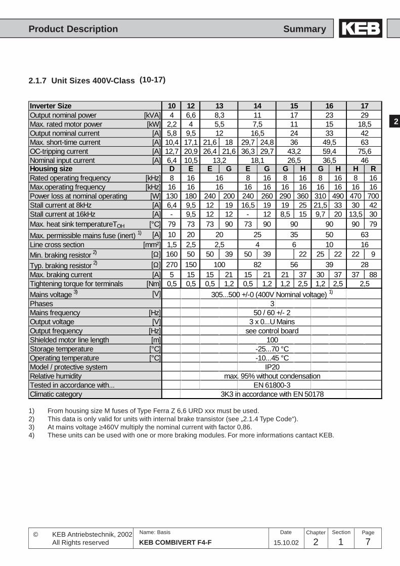
2.1.7 Unit Sizes 400V-Class
1) From housing size M fuses of Type Ferra Z 6,6 URD xxx must be used.2) This data is only valid for units with internal brake transistor (see „2.1.4 Type Code“).3) At mains voltage ≥460V multiply the nominal current with factor 0,86.4) These units can be used with one or more braking modules. For more informations cantact KEB.
Inverter Size 10 12 13 14 15 16 17Output nominal power [kVA] 4 6,6 8,3 11 17 23 29Max. rated motor power [kW] 2,2 4 5,5 7,5 11 15 18,5Output nominal current [A] 5,8 9,5 12 16,5 24 33 42Max. short-time current [A] 10,4 17,1 21,6 18 29,7 24,8 36 49,5 63OC-tripping current [A] 12,7 20,9 26,4 21,6 36,3 29,7 43,2 59,4 75,6Nominal input current [A] 6,4 10,5 13,2 18,1 26,5 36,5 46Housing size D E E G E G G H G H H RRated operating frequency [kHz] 8 16 16 8 16 8 16 8 16 8 16Max.operating frequency [kHz] 16 16 16 16 16 16 16 16 16 16 16Power loss at nominal operating [W] 130 180 240 200 240 260 290 360 310 490 470 700Stall current at 8kHz [A] 6,4 9,5 12 19 16,5 19 19 25 21,5 33 30 42Stall current at 16kHz [A] - 9,5 12 12 - 12 8,5 15 9,7 20 13,5 30Max. heat sink temperatureTOH [°C] 79 73 73 90 73 90 90 90 90 79
Max. permissible mains fuse (inert) 1) [A] 10 20 20 25 35 50 63Line cross section [mm²] 1,5 2,5 2,5 4 6 10 16Min. braking resistor 2) [Ω] 160 50 50 39 50 39 22 25 22 22 9
Typ. braking resistor 2) [Ω] 270 150 100 82 56 39 28Max. braking current [A] 5 15 15 21 15 21 21 37 30 37 37 88Tightening torque for terminals [Nm] 0,5 0,5 0,5 1,2 0,5 1,2 1,2 2,5 1,2 2,5 2,5
Mains voltage 3) [V] 305...500 +/-0 (400V Nominal voltage) 1)
Phases 3Mains frequency [Hz] 50 / 60 +/- 2Output voltage [V] 3 x 0...U MainsOutput frequency [Hz] see control boardShielded motor line length [m] 100Storage temperature [°C] -25...70 °COperating temperature [°C] -10...45 °CModel / protective system IP20Relative humidity max. 95% without condensationTested in accordance with... EN 61800-3Climatic category 3K3 in accordance with EN 50178
(10-17)
© KEB Antriebstechnik, 2002All rights reserved
Chapter Section Page Date
2 1 KEB COMBIVERT F4-F8Name: Basis
15.10.02
Product DescriptionSummary
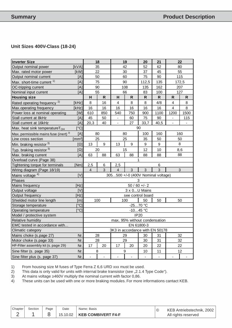
Unit Sizes 400V-Class (18-24)
1) From housing size M fuses of Type Ferra Z 6,6 URD xxx must be used.2) This data is only valid for units with internal brake transistor (see „2.1.4 Type Code“).3) At mains voltage ≥460V multiply the nominal current with factor 0,86.4) These units can be used with one or more braking modules. For more informations cantact KEB.
Inverter Size 18 19 20 21 22Output nominal power [kVA] 35 42 52 62 80Max. rated motor power [kW] 22 30 37 45 55Output nominal current [A] 50 60 75 90 115
Max. short-time current 1) [A] 75 90 112,5 135 172,5OC-tripping current [A] 90 108 135 162 207Nominal input current [A] 55 66 83 100 127Housing size H R H R R R R R
Rated operating frequency 2) [kHz] 8 16 4 8 8 4/8 4 8Max.operating frequency [kHz] 16 16 16 16 16 16 4 8Power loss at nominal operating [W] 610 850 540 750 900 1100 1200 1500Stall current at 8kHz [A] 45 50 - 60 75 90 - 115Stall current at 16kHz [A] 20,3 40 - 27 33,7 40,5 - -Max. heat sink temperatureTOH [°C]
Max. permissible mains fuse (inert) 2) [A] 80 80 100 160 160Line cross section [mm²] 25 25 35 50 50
Min. braking resistor 3) [Ω] 13 9 13 9 9 9
Typ. braking resistor 3) [Ω] 20 15 12 10 8,6Max. braking current [A] 63 88 63 88 88 88Overload curve (Page 38) 1Tightening torque for terminals [Nm] 2,5 6 2,5 6Wiring diagram (Page 18/19) 4 3 4 3 3 3 3
Mains voltage 4) [V] 305...500 +/-0 (400V Nominal voltage)Phases 3Mains frequency [Hz] 50 / 60 +/- 2Output voltage [V] 3 x 0...U MainsOutput frequency [Hz] see control boardShielded motor line length [m] 100 100 50 50 50Storage temperature [°C] -25...70 °COperating temperature [°C] -10...45 °CModel / protective system IP20Relative humidity max. 95% without condensationEMC tested in accordance with... EN 61800-3Climatic category 3K3 in accordance with EN 50178Mains choke (s.page 27) Nr. 28 29 30 31 32Motor choke (s.page 33) Nr. 28 29 30 31 32HF-Filter assembly kit (s. page 29) Nr. 17 20 17 20 20 22 22
Sine filter (s. page 35) Nr. 8 9 10 11 12
Sine filter plus (s. page 37) Nr. - - - - - - - -
8
88
90
2
© KEB Antriebstechnik, 2002All Rights reserved
Chapter Section PageDate
2 1 9KEB COMBIVERT F4-F
Name: Basis
15.10.02
Product Description Summary
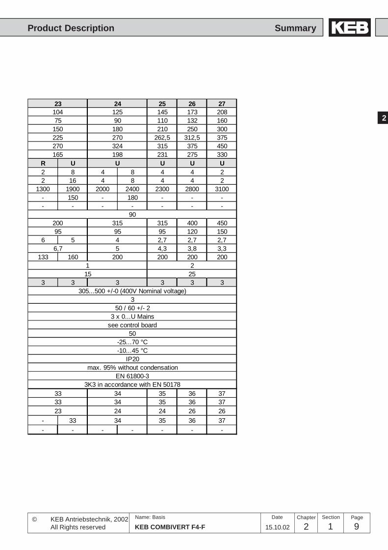
23 24 25 26 27104 125 145 173 20875 90 110 132 160
150 180 210 250 300225 270 262,5 312,5 375270 324 315 375 450165 198 231 275 330
R U U U U U2 8 4 8 4 4 22 16 4 8 4 4 2
1300 1900 2000 2400 2300 2800 3100- 150 - 180 - - -- - - - - - -
90200 315 315 400 45095 95 95 120 150
6 5 4 2,7 2,7 2,76,7 5 4,3 3,8 3,3
133 160 200 200 200 2001 215 25
3 3 3 3 3 3305...500 +/-0 (400V Nominal voltage)
350 / 60 +/- 2
3 x 0...U Mainssee control board
50-25...70 °C-10...45 °C
IP20max. 95% without condensation
EN 61800-33K3 in accordance with EN 50178
33 34 35 36 3733 34 35 36 3723 24 24 26 26
- 33 34 35 36 37
- - - - - - -

© KEB Antriebstechnik, 2002All rights reserved
Chapter Section Page Date
2 1 KEB COMBIVERT F4-F10Name: Basis
15.10.02
Product DescriptionSummary
3 1 1KEB COMBIVERT F4-F
Name: Basis
18.12.02
Hardware
Chapter Section PageDate© KEB Antriebstechnik, 2002All Rights reserved
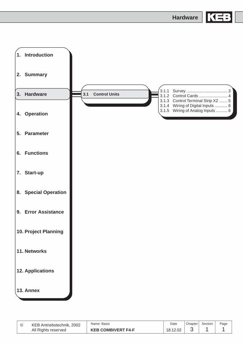
3.1 Control Units
1. Introduction
2. Summary
3. Hardware
4. Operation
5. Parameter
6. Functions
7. Start-up
8. Special Operation
9. Error Assistance
10. Project Planning
11. Networks
12. Applications
13. Annex
3.1.1 Survey .................................... 33.1.2 Control Cards ......................... 43.1.3 Control Terminal Strip X2 ....... 53.1.4 Wiring of Digital Inputs ........... 63.1.5 Wiring of Analog Inputs .......... 6

3 1 KEB COMBIVERT F4-F2Name: Basis
18.12.02
Chapter Section Page Date © KEB Antriebsteclnik, 2002All Rights reserved
Hardware Control Cards
3 1 3KEB COMBIVERT F4-F
Name: Basis
18.12.02
3
Section PageDate© KEB Antriebstechnik, 2002All Rights reserved
Chapter
HardwareControl Cards
STARTSTOP
ENTERF/R
FUNC.SPEED
STARTSTOP
ENTERF/R
FUNC.SPEED
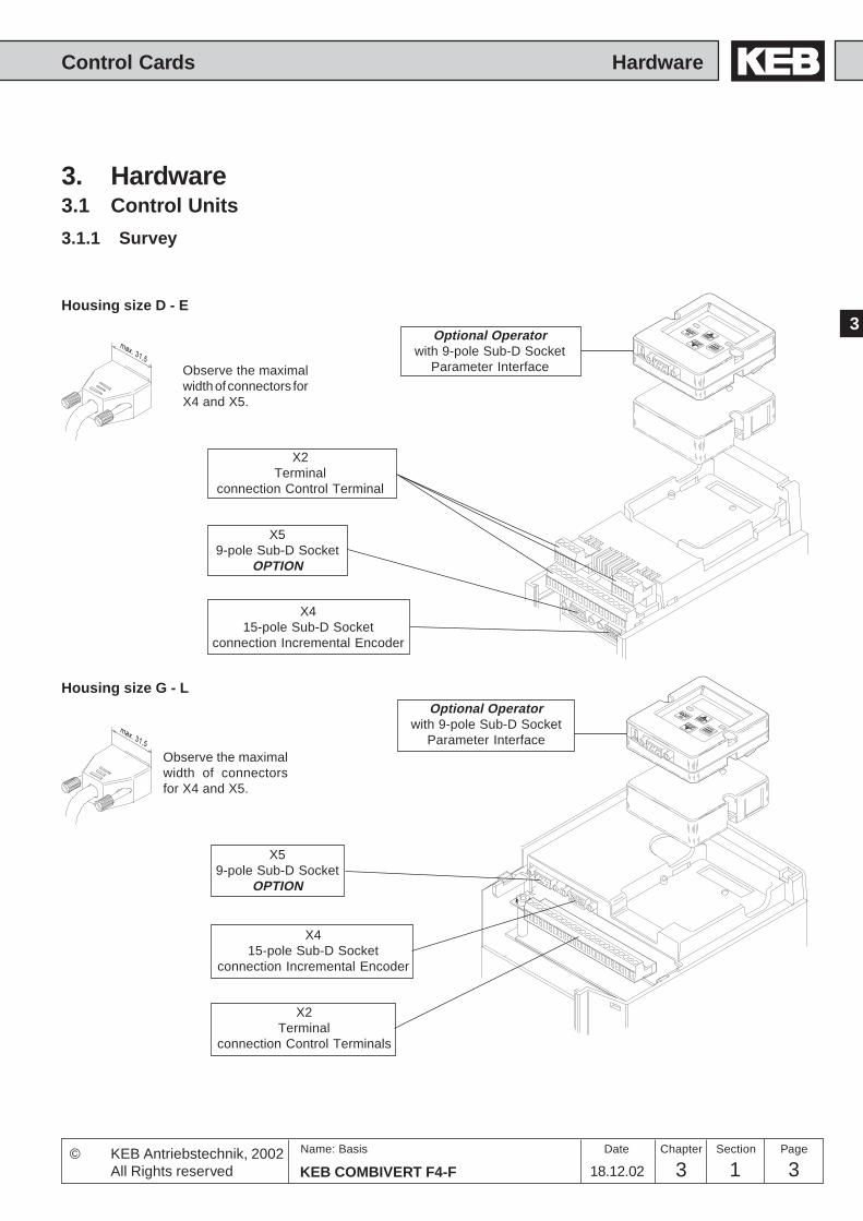
Housing size G - L
Housing size D - E
Optional Operatorwith 9-pole Sub-D Socket
Parameter Interface
3.1.1 Survey
3.1 Control Units3. Hardware
X415-pole Sub-D Socket
connection Incremental Encoder
X59-pole Sub-D Socket
OPTION
X2Terminal
connection Control Terminal
X415-pole Sub-D Socket
connection Incremental Encoder
X59-pole Sub-D Socket
OPTION
X2Terminal
connection Control Terminals
Optional Operatorwith 9-pole Sub-D Socket
Parameter Interface
Observe the maximalwidth of connectors forX4 and X5.
Observe the maximalwidth of connectorsfor X4 and X5.
3 1 KEB COMBIVERT F4-F4Name: Basis
18.12.02
Chapter Section Page Date © KEB Antriebsteclnik, 2002All Rights reserved
Hardware Control Cards
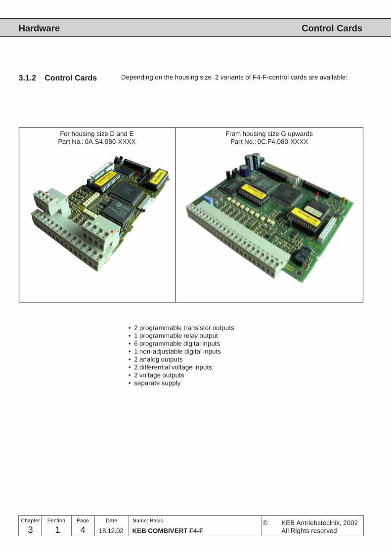
Depending on the housing size 2 variants of F4-F-control cards are available:
• 2 programmable transistor outputs• 1 programmable relay output• 6 programmable digital inputs• 1 non-adjustable digital inputs• 2 analog outputs• 2 differential voltage inputs• 2 voltage outputs• separate supply
For housing size D and EPart No.: 0A.S4.080-XXXX
From housing size G upwardsPart No.: 0C.F4.080-XXXX
3.1.2 Control Cards
3 1 5KEB COMBIVERT F4-F
Name: Basis
18.12.02
3
Section PageDate© KEB Antriebstechnik, 2002All Rights reserved
Chapter
HardwareControl Cards
20 22 231 2 3 4 21
16 17 185 6 7 8 9 10 11 12 13 14 15 191 2 3 4 5 6 7 8 9 10 11 12 13 14 15 16 17 18 19 20 21 22 23
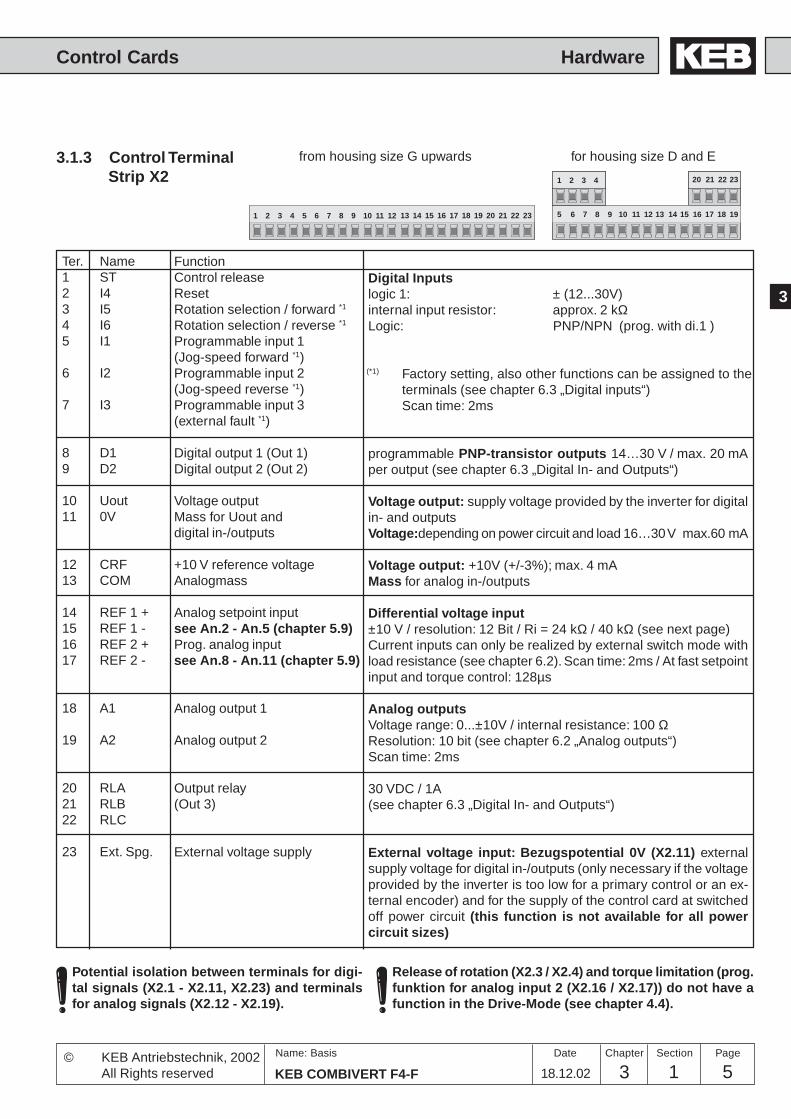
3.1.3 Control TerminalStrip X2
for housing size D and Efrom housing size G upwards
Ter. Name1 ST2 I43 I54 I65 I1
6 I2
7 I3
8 D19 D2
10 Uout11 0V
12 CRF13 COM
14 REF 1 +15 REF 1 -16 REF 2 +17 REF 2 -
18 A1
19 A2
20 RLA21 RLB22 RLC
23 Ext. Spg.
FunctionControl releaseResetRotation selection / forward *1
Rotation selection / reverse *1
Programmable input 1(Jog-speed forward *1)Programmable input 2(Jog-speed reverse *1)Programmable input 3(external fault *1)
Digital output 1 (Out 1)Digital output 2 (Out 2)
Voltage outputMass for Uout anddigital in-/outputs
+10 V reference voltageAnalogmass
Analog setpoint inputsee An.2 - An.5 (chapter 5.9)Prog. analog inputsee An.8 - An.11 (chapter 5.9)
Analog output 1
Analog output 2
Output relay(Out 3)
External voltage supply
Digital Inputslogic 1: ± (12...30V)internal input resistor: approx. 2 kΩLogic: PNP/NPN (prog. with di.1 )
(*1) Factory setting, also other functions can be assigned to theterminals (see chapter 6.3 „Digital inputs“)Scan time: 2ms
programmable PNP-transistor outputs 14…30 V / max. 20 mAper output (see chapter 6.3 „Digital In- and Outputs“)
Voltage output: supply voltage provided by the inverter for digitalin- and outputsVoltage:depending on power circuit and load 16…30 V max.60 mA
Voltage output: +10V (+/-3%); max. 4 mAMass for analog in-/outputs
Differential voltage input±10 V / resolution: 12 Bit / Ri = 24 kΩ / 40 kΩ (see next page)Current inputs can only be realized by external switch mode withload resistance (see chapter 6.2). Scan time: 2ms / At fast setpointinput and torque control: 128µs
Analog outputsVoltage range: 0...±10V / internal resistance: 100 ΩResolution: 10 bit (see chapter 6.2 „Analog outputs“)Scan time: 2ms
30 VDC / 1A(see chapter 6.3 „Digital In- and Outputs“)
External voltage input: Bezugspotential 0V (X2.11) externalsupply voltage for digital in-/outputs (only necessary if the voltageprovided by the inverter is too low for a primary control or an ex-ternal encoder) and for the supply of the control card at switchedoff power circuit (this function is not available for all powercircuit sizes)
Potential isolation between terminals for digi-tal signals (X2.1 - X2.11, X2.23) and terminalsfor analog signals (X2.12 - X2.19).
Release of rotation (X2.3 / X2.4) and torque limitation (prog.funktion for analog input 2 (X2.16 / X2.17)) do not have afunction in the Drive-Mode (see chapter 4.4).
3 1 KEB COMBIVERT F4-F6Name: Basis
18.12.02
Chapter Section Page Date © KEB Antriebsteclnik, 2002All Rights reserved
Hardware Control Cards
........
+
12 13 14 15 16 17 18 19CRF COM REF1 REF1 REF2 REF2 A1 A2
+ – + –
1) 20 21 22RLA RLB RLC
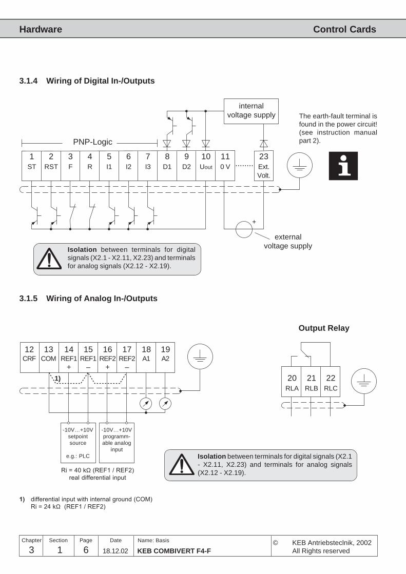
3.1.4 Wiring of Digital In-/Outputs
3.1.5 Wiring of Analog In-/Outputs
-10V…+10Vsetpointsource
e.g.: PLC
-10V…+10Vprogramm-able analog
input
Output Relay
Ri = 40 kΩ (REF1 / REF2)real differential input
1) differential input with internal ground (COM)Ri = 24 kΩ (REF1 / REF2)
Isolation between terminals for digital signals (X2.1- X2.11, X2.23) and terminals for analog signals(X2.12 - X2.19).
internalvoltage supply
1 2 3 4 5 6 7 8 9 10 11 23ST RST F R I1 I2 I3 D1 D2 Uout 0 V Ext.
Volt.
PNP-Logic
The earth-fault terminal isfound in the power circuit!(see instruction manualpart 2).
Isolation between terminals for digitalsignals (X2.1 - X2.11, X2.23) and terminalsfor analog signals (X2.12 - X2.19).
externalvoltage supply
4 1 1KEB COMBIVERT F4-F
Name: Basis
1. Introduction
2. Summary
3. Hardware
4. Operation
5. Parameter
6. Functions
7. Start-up
8. Special Operation
9. Error Assistance
10. Project Planning
11. Networks
12. Applications
13. Annex
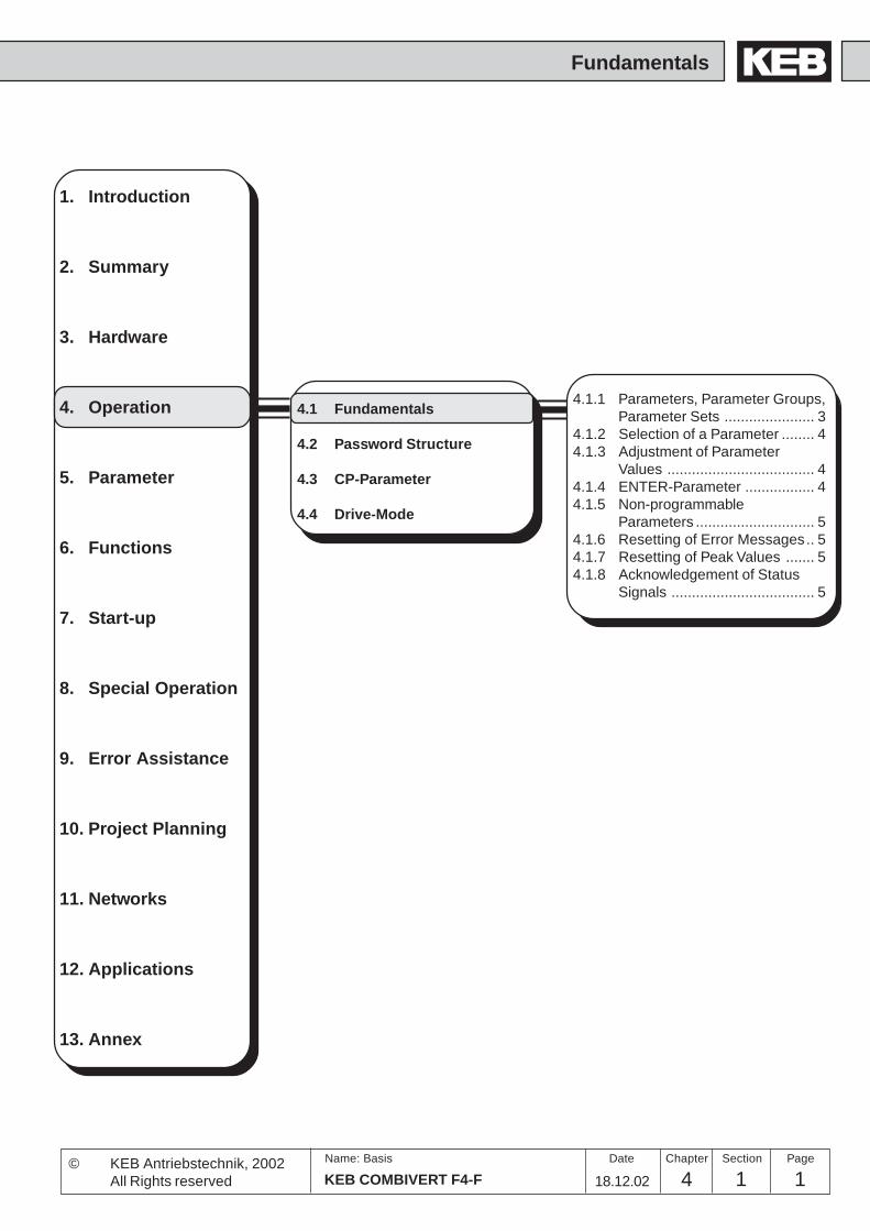
4.1 Fundamentals
4.2 Password Structure
4.3 CP-Parameter
4.4 Drive-Mode
Fundamentals
Chapter Section PageDate
18.12.02© KEB Antriebstechnik, 2002
All Rights reserved
4.1.1 Parameters, Parameter Groups,Parameter Sets ...................... 3
4.1.2 Selection of a Parameter ........ 44.1.3 Adjustment of Parameter
Values .................................... 44.1.4 ENTER-Parameter ................. 44.1.5 Non-programmable
Parameters ............................. 54.1.6 Resetting of Error Messages.. 54.1.7 Resetting of Peak Values ....... 54.1.8 Acknowledgement of Status
Signals ................................... 5

4 1 KEB COMBIVERT F4-F2Name: Basis
Operation Fundamentals
Chapter Section Page Date
18.12.02© KEB Antriebstechnik, 2002
All Rights reserved

KEB COMBIVERT F4-F
Name: Basis
4 1 3
4
OperationFundamentals
Section PageDate Chapter
18.12.02© KEB Antriebstechnik, 2002
All Rights reserved
4.1.1 Parameters, Para-meter Groups,Parameter Sets
4.1 Fundamentals
The following chapter describes the fundumentals of the software structure as wellas the operation of the unit.
The control board F4-F incorporates 3 operating modes:
Operating Modes ofControl Board F4-F
Customer Mode
- is a list of parameters(CP-Parameter), freelydefinable, which arenecessary or importantfor the user.
- suppllied with a para-meter list defined byKEB
Application Mode
- all parameter groups(exception: CP-parameter) andparameter sets can beselected and, ifnecessary, changed
- usually it is activatedonly for the adaption tothe application
Drive Mode
- with this special mode,the unit can be put intooperation via operator
- with the exception of thecontrol release noterminal wiring isneeded
What are parameters, parameter groups and parameter sets?
Parameters are values changeable by the operator in a program, which have aninfluence on the program flow. A parameter consists of
Parameter designation and Parameter value
Example:
Each parameter is
clearly specified!The parameter value shows theactual setting.
The parameter number specifies the parameterswithin a group.
To maintain a cleary-to-survey operation inspite of the greatnumber of parameters, we have combined function-relatedparameters into parameter groups (e.g. all motor-relatedparameters are combined in the Drive(dr)-group).
8 parameter sets (0...7) exist to adjust several values for oneparameter. If the active values shall be displayed for a running unitthe digit is set to „A“. The digit is not-applicable for non-programmableparameters.
A conveyor belt shall be used with 3 different speeds. A parameter set is programmedfor each „speed“ ... acceleration, deceleration etc. can be adjusted individually.
4. Operation
4 1 KEB COMBIVERT F4-F4Name: Basis
Operation Fundamentals
Chapter Section Page Date
18.12.02© KEB Antriebstechnik, 2002
All Rights reserved
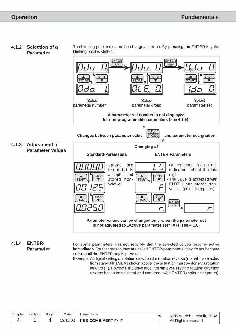
4.1.2 Selection of aParameter
The blinking point indicates the changeable area. By pressing the ENTER-key theblinking point is shifted.
ENTERF/R
ENTERF/R
START
STOP START
STOP START
STOP
Select Select Selectparameter number parameter group parameter set
A parameter set number is not displayedfor non-programmable parameters (see 4.1.5)!
Changes between parameter valueFUNCTSPEED and parameter designation
Changing of
Standard-Parameters ENTER-Parameters
START
STOP
START
STOP
START
STOP
START
STOP
ENTERF/R
Parameter values can be changed only, when the parameter setis not adjusted to „Active parameter set“ (A) ! (see 4.1.6)
For some parameters it is not sensible that the selected values become activeimmediately. For that reason they are called ENTER-parameters, they do not becomeactive until the ENTER-key is pressed.Example: At digital setting of rotation direction the rotation reverse (r) shall be selected
from standstill (LS). As shown above, the actuation must be done via rotationforward (F). However, the drive must not start yet, first the rotation directionreverse has to be selected and confirmed with ENTER (point disappears).
4.1.3 Adjustment ofParameter Values
4.1.4 ENTER-Parameter
- Values areimmediatelyaccepted andstored non-volatile!
- During changing a point isindicated behind the lastdigit
- The value is accepted withENTER and stored non-volatile (point disappears)
KEB COMBIVERT F4-F
Name: Basis
4 1 5
4
OperationFundamentals
Section PageDate Chapter
18.12.02© KEB Antriebstechnik, 2002
All Rights reserved
4.1.5 Non-programmableParameters
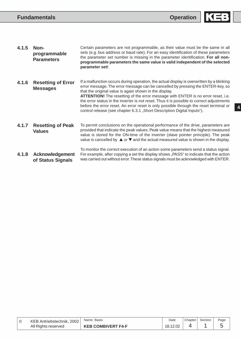
Certain parameters are not programmable, as their value must be the same in allsets (e.g. bus address or baud rate). For an easy identification of these parametersthe parameter set number is missing in the parameter identification. For all non-programmable parameters the same value is valid independent of the selectedparameter set!
If a malfunction occurs during operation, the actual display is overwritten by a blinkingerror message. The error message can be cancelled by pressing the ENTER-key, sothat the original value is again shown in the display.ATTENTION! The resetting of the error message with ENTER is no error reset, i.e.the error status in the inverter is not reset. Thus it is possible to correct adjustmentsbefore the error reset. An error reset is only possible through the reset terminal orcontrol release (see chapter 6.3.1 „Short Description Digital Inputs“).
To permit conclusions on the operational performance of the drive, parameters areprovided that indicate the peak values. Peak value means that the highest measuredvalue is stored for the ON-time of the inverter (slave pointer principle). The peakvalue is cancelled by or and the actual measured value is shown in the display.
To monitor the correct execution of an action some parameters send a status signal.For example, after copying a set the display shows „PASS“ to indicate that the actionwas carried out without error. These status signals must be acknowledged with ENTER.
4.1.6 Resetting of ErrorMessages
4.1.7 Resetting of PeakValues
4.1.8 Acknowledgementof Status Signals

4 1 KEB COMBIVERT F4-F6Name: Basis
Operation Fundamentals
Chapter Section Page Date
18.12.02© KEB Antriebstechnik, 2002
All Rights reserved
ANTRIEBSTECHNIK
4 2 1KEB COMBIVERT F4-F
Name: Basis
Operation
1. Introduction
2. Summary
3. Hardware
4. Operation
5. Parameter
6. Functions
7. Start-up
8. Special Operation
9. Error Assistance
10. Project Planning
11. Networks
12. Applications
13. Annex
4.1 Fundamentals
4.2 Password Structure
4.3 CP-Parameter
4.4 Drive-Mode
Chapter Section PageDate
18.12.02© KEB Antriebstechnik, 2002
All Rights reserved
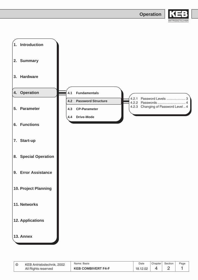
4.2.1 Password Levels .................... 34.2.2 Passwords .............................. 44.2.3 Changing of Password Level .. 4

4 2 KEB COMBIVERT F4-F2Name: Basis
Operation Password Structure
Chapter Section Page Date
18.12.02© KEB Antriebstechnik, 2002
All Rights reserved
3
ANTRIEBSTECHNIK
4 2 3KEB COMBIVERT F4-F
Name: Basis
4
Password Structure Operation
Section PageDate Chapter
18.12.02© KEB Antriebstechnik, 2002
All Rights reserved
4.2 PasswordStructure
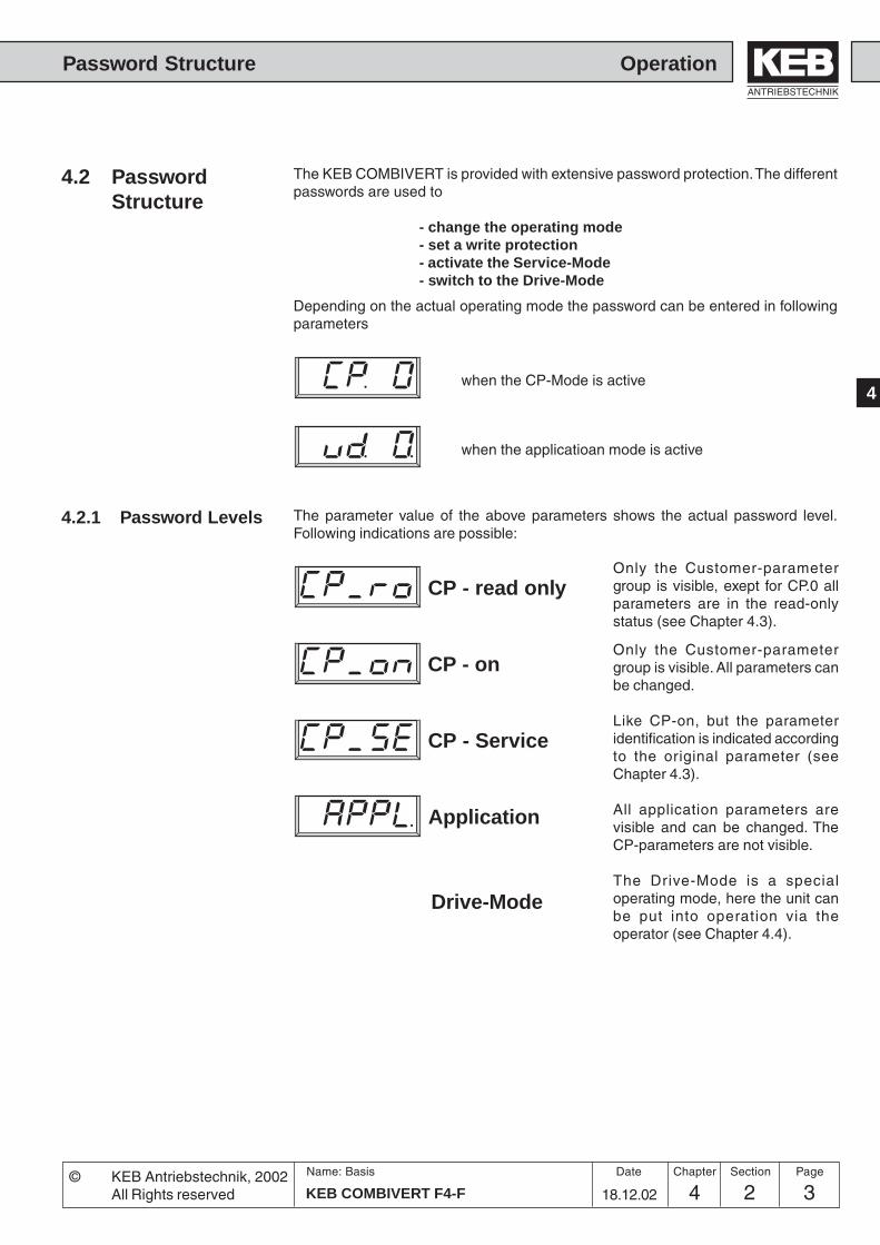
The KEB COMBIVERT is provided with extensive password protection. The differentpasswords are used to
- change the operating mode- set a write protection- activate the Service-Mode- switch to the Drive-Mode
Depending on the actual operating mode the password can be entered in followingparameters
when the CP-Mode is active
when the applicatioan mode is active
The parameter value of the above parameters shows the actual password level.Following indications are possible:
CP - read only
CP - on
CP - Service
Application
Drive-Mode
4.2.1 Password Levels
Only the Customer-parametergroup is visible, exept for CP.0 allparameters are in the read-onlystatus (see Chapter 4.3).
Only the Customer-parametergroup is visible. All parameters canbe changed.
Like CP-on, but the parameteridentification is indicated accordingto the original parameter (seeChapter 4.3).
All application parameters arevisible and can be changed. TheCP-parameters are not visible.
The Drive-Mode is a specialoperating mode, here the unit canbe put into operation via theoperator (see Chapter 4.4).
4 2 KEB COMBIVERT F4-F4Name: Basis
Operation Password Structure
Chapter Section Page Date
18.12.02© KEB Antriebstechnik, 2002
All Rights reserved
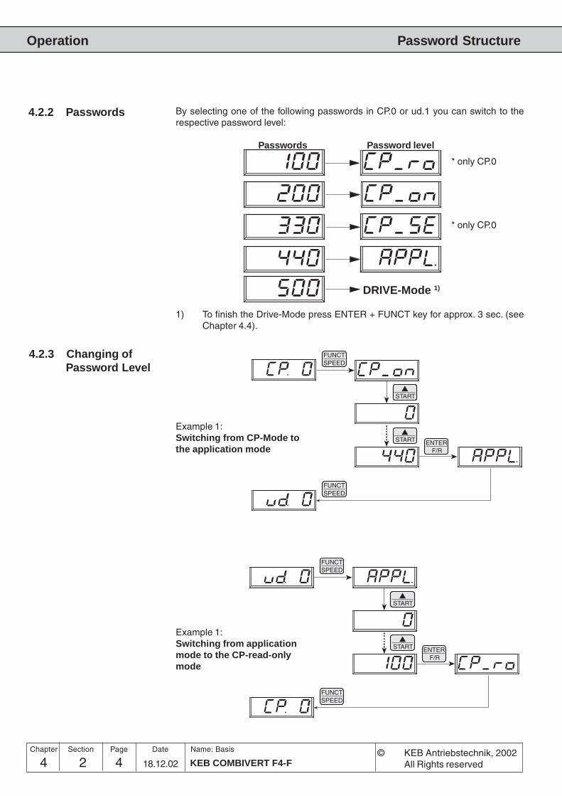
4.2.2 Passwords
4.2.3 Changing ofPassword Level
By selecting one of the following passwords in CP.0 or ud.1 you can switch to therespective password level:
Passwords Password level
DRIVE-Mode 1)
START
ENTERF/R
FUNCTSPEED
START
START
FUNCTSPEED
1) To finish the Drive-Mode press ENTER + FUNCT key for approx. 3 sec. (seeChapter 4.4).
Example 1:Switching from CP-Mode tothe application mode
Example 1:Switching from applicationmode to the CP-read-onlymode
START
ENTERF/R
FUNCTSPEED
START
START
FUNCTSPEED
* only CP.0
* only CP.0
4 3 1KEB COMBIVERT F4-F
Name: Basis
18.12.02
1. Introduction
2. Summary
3. Hardware
4. Operation
5. Parameter
6. Functions
7. Start-up
8. Special Operation
9. Error Assistance
10. Project Planning
11. Networks
12. Applications
13. Annex
4.1 Fundamentals
4.2 Password Structure
4.3 CP-Parameter
4.4 Drive-Mode
Operation
© KEB Antriebstechnik, 2002All rights reserved
Chapter Section PageDate
4.3.1 Operation in CP-Mode ........... 34.3.2 Factory Setting ....................... 34.3.3 Description of
CP-Parameter ........................ 5

4 3 KEB COMBIVERT F4-F2Name: Basis
18.12.02
CP - Parameter
© KEB Antriebstechnik, 2002All Rights reserved
Operation
Chapter Section Page Date
34 3 3KEB COMBIVERT F4-F
Name: Basis
18.12.02
4
CP - Parameter
© KEB Antriebstechnik, 2002All Rights reserved
Operation
Chapter Section PageDate
4.3.1 Operation inCP-Mode
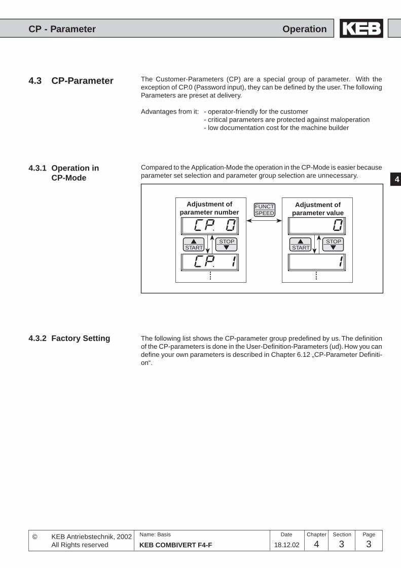
4.3 CP-Parameter The Customer-Parameters (CP) are a special group of parameter. With theexception of CP.0 (Password input), they can be defined by the user. The followingParameters are preset at delivery.
Advantages from it: - operator-friendly for the customer- critical parameters are protected against maloperation- low documentation cost for the machine builder
FUNCTSPEED
START
STOP START
STOP
Adjustment ofparameter number
Adjustment ofparameter value
Compared to the Application-Mode the operation in the CP-Mode is easier becauseparameter set selection and parameter group selection are unnecessary.
The following list shows the CP-parameter group predefined by us. The definitionof the CP-parameters is done in the User-Definition-Parameters (ud). How you candefine your own parameters is described in Chapter 6.12 „CP-Parameter Definiti-on“.
4.3.2 Factory Setting
4 3 KEB COMBIVERT F4-F4Name: Basis
18.12.02
CP - Parameter
© KEB Antriebstechnik, 2002All Rights reserved
Operation
Chapter Section Page Date
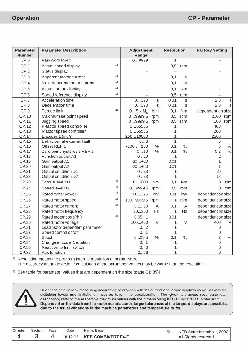
Parameter Parameter Describtion Adjustment Resolution Factory SettingNumber Range
CP.0 Password Input 0…9999 1 –CP.1 Actual speed display 1) – 0,5 rpm –CP.2 Status display – – –CP.3 Apparent motor current 1) – 0,1 A –CP.4 Max. apparent motor current 1) – 0,1 A –CP.5 Actual torque display 1) – 0,1 Nm –CP.6 Speed reference display 1) – 0,5 rpm –CP.7 Acceleration time 0…320 s 0,01 s 2,0 sCP.8 Deceleration time 0…320 s 0,01 s 2,0 sCP.9 Torque limit 2) 0…5 x M
NNm 0,1 Nm dependent on size
CP.10 Maximum setpoint speed 0…9999,5 rpm 0,5 rpm 2100 rpmCP.11 Jogging speed 0…9999,5 rpm 0,5 rpm 100 rpmCP.12 P-factor speed controller 0…65535 1 400CP.13 I-factor speed controller 0…65535 1 200CP.14 Encoder 1 (inc/r) 256…10000 1 2500CP.15 Behaviour at external fault 0…6 1 0CP.16 Offset REF 1 -100…+100 % 0,1 % 0 %CP.17 Zero point hysteresis REF 1 0…10 % 0,1 % 0,2 %CP.18 Function output A1 0…10 1 2CP.19 Gain output A1 -20…+20 0,01 1CP.20 Gain output A2 -20…+20 0,01 1CP.21 Output condition D1 0…33 1 20CP.22 Output condition D2 0…33 1 18CP.23 Torque level D1 1) 0…2000 Nm 0,1 Nm 0 NmCP.24 Speed level D2 1) 0…9999,5 rpm 0,5 rpm 0 rpmCP.25 Rated motor power 2) 0,01...75 kW 0,01 kW dependent on sizeCP.26 Rated motor speed 2) 100...9999,5 rpm 1 rpm dependent on sizeCP.27 Rated motor current 2) 0,1...50 A 0,1 A dependent on sizeCP.28 Rated motor frequency 20...300 Hz 1 Hz dependent on sizeCP.29 Rated motor cos (Phi) 2) 0,05...1 0,01 dependent on sizeCP.30 Rated motor voltage 100...400 V 1 V 400 VCP.31 Load motor dependent parameter 0...2 1 0CP.32 Speed control on/off 0...1 1 0CP.33 Boost 0...25,5 % 0,1 % 2 %CP.34 Change encoder 1 rotation 0...1 1 0CP.35 Reaction to limit switch 0...6 1 6CP.36 Aux function 0...96 1 0
1) Resolution means the program internal resolution of parameters.The accuracy of the detection / calculation of the parameter values may be worse than the resolution.
2) See table for parameter values that are dependent on the size (page GB 35)!
Due to the calculation / measuring accuracies, tolerances with the current and torque displays as well as with theswitching levels and limitations, must be taken into consideration. The given tolerances (see parameterdescription) refer to the respective maximum values with the dimensioning KEB COMBIVERT: Motor = 1:1.Dependent on the data from the motor manufacturer, larger tolerances at the torque displays are possible,due to the usual variations in the machine parameters and temperature drifts.
54 3 5KEB COMBIVERT F4-F
Name: Basis
18.12.02
4
CP - Parameter
© KEB Antriebstechnik, 2002All Rights reserved
Operation
Chapter Section PageDate
Enabling of CP-Parameter
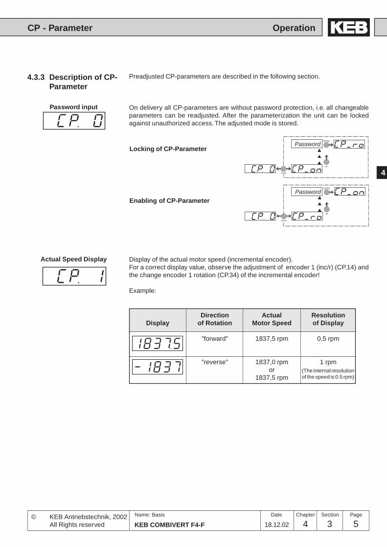
Preadjusted CP-parameters are described in the following section.
On delivery all CP-parameters are without password protection, i.e. all changeableparameters can be readjusted. After the parameterization the unit can be lockedagainst unauthorized access. The adjusted mode is stored.
4.3.3 Description of CP-Parameter
FUNC
ENTER
UP
Password
Password
FUNC
ENTER
UP
Locking of CP-Parameter
Password input
Direction Actual ResolutionDisplay of Rotation Motor Speed of Display
"forward" 1837,5 rpm 0,5 rpm
"reverse" 1837,0 rpm 1 rpmor
1837,5 rpm
Display of the actual motor speed (incremental encoder).For a correct display value, observe the adjustment of encoder 1 (inc/r) (CP.14) andthe change encoder 1 rotation (CP.34) of the incremental encoder!
Example:
Actual Speed Display
(The internal resolutionof the speed is 0.5 rpm)
4 3 KEB COMBIVERT F4-F6Name: Basis
18.12.02
CP - Parameter
© KEB Antriebstechnik, 2002All Rights reserved
Operation
Chapter Section Page Date
Abnormal
Stopping
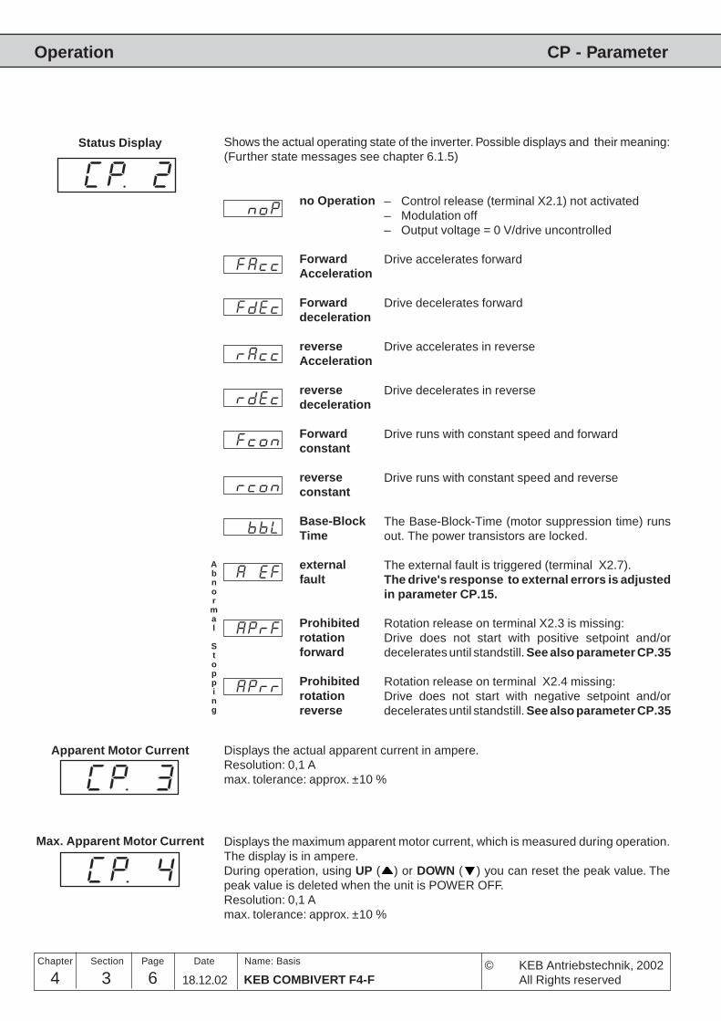
Status Display Shows the actual operating state of the inverter. Possible displays and their meaning:(Further state messages see chapter 6.1.5)
no Operation
ForwardAcceleration
Forwarddeceleration
reverseAcceleration
reversedeceleration
Forwardconstant
reverseconstant
Base-BlockTime
externalfault
Prohibitedrotationforward
Prohibitedrotationreverse
– Control release (terminal X2.1) not activated– Modulation off– Output voltage = 0 V/drive uncontrolled
Drive accelerates forward
Drive decelerates forward
Drive accelerates in reverse
Drive decelerates in reverse
Drive runs with constant speed and forward
Drive runs with constant speed and reverse
The Base-Block-Time (motor suppression time) runsout. The power transistors are locked.
The external fault is triggered (terminal X2.7).The drive's response to external errors is adjustedin parameter CP.15.
Rotation release on terminal X2.3 is missing:Drive does not start with positive setpoint and/ordecelerates until standstill. See also parameter CP.35
Rotation release on terminal X2.4 missing:Drive does not start with negative setpoint and/ordecelerates until standstill. See also parameter CP.35
Displays the actual apparent current in ampere.Resolution: 0,1 Amax. tolerance: approx. ±10 %
Apparent Motor Current
Displays the maximum apparent motor current, which is measured during operation.The display is in ampere.During operation, using UP ( ) or DOWN ( ) you can reset the peak value. Thepeak value is deleted when the unit is POWER OFF.Resolution: 0,1 Amax. tolerance: approx. ±10 %
Max. Apparent Motor Current
74 3 7KEB COMBIVERT F4-F
Name: Basis
18.12.02
4
CP - Parameter
© KEB Antriebstechnik, 2002All Rights reserved
Operation
Chapter Section PageDate
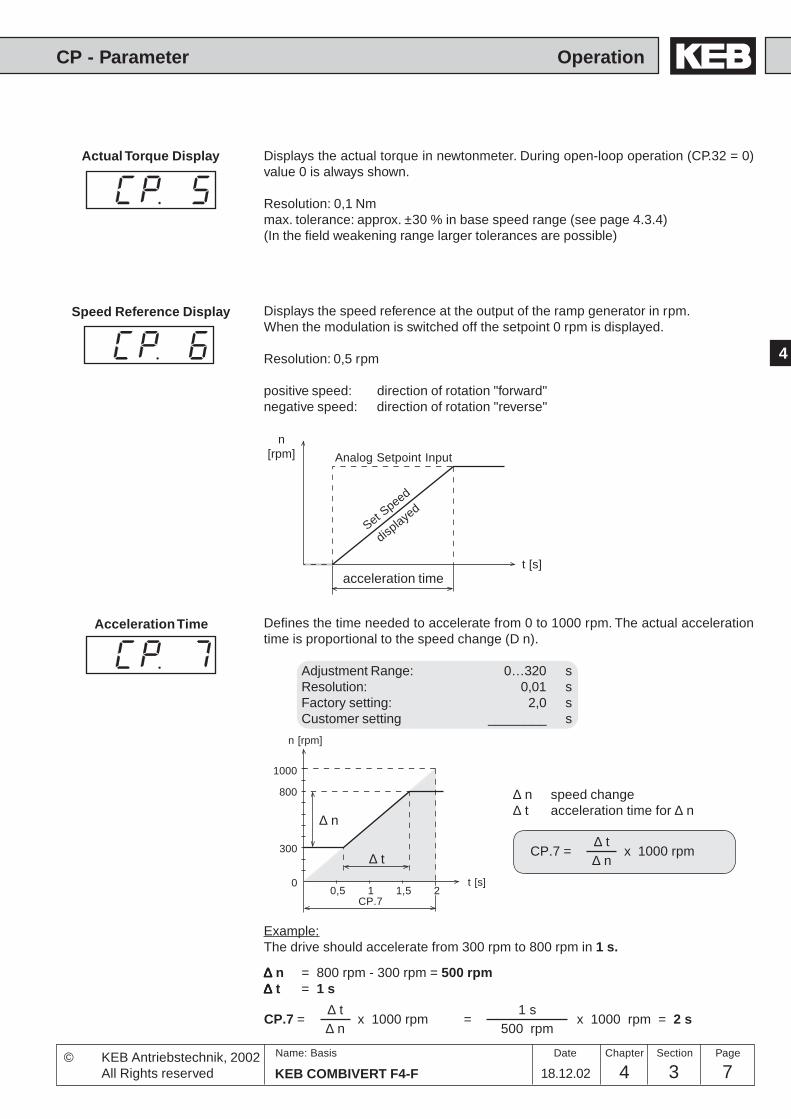
Actual Torque Display Displays the actual torque in newtonmeter. During open-loop operation (CP.32 = 0)value 0 is always shown.
Resolution: 0,1 Nmmax. tolerance: approx. ±30 % in base speed range (see page 4.3.4)(In the field weakening range larger tolerances are possible)
Speed Reference Display Displays the speed reference at the output of the ramp generator in rpm.When the modulation is switched off the setpoint 0 rpm is displayed.
Resolution: 0,5 rpm
positive speed: direction of rotation "forward"negative speed: direction of rotation "reverse"
acceleration time
Set Speed
displaye
d
Analog Setpoint Input
t [s]
n[rpm]
Defines the time needed to accelerate from 0 to 1000 rpm. The actual accelerationtime is proportional to the speed change (D n).
Adjustment Range: 0…320 sResolution: 0,01 sFactory setting: 2,0 sCustomer setting ________ s
∆ n speed change∆ t acceleration time for ∆ n
Acceleration Time
∆ tCP.7 = x 1000 rpm
∆ n
Example:The drive should accelerate from 300 rpm to 800 rpm in 1 s.
∆∆∆∆∆ n = 800 rpm - 300 rpm = 500 rpm∆∆∆∆∆ t = 1 s
∆ t 1 sCP.7 = x 1000 rpm = x 1000 rpm = 2 s
∆ n 500 rpm
t [s]
CP.7
n [rpm]
1000
800
300
00,5 1 1,5 2
∆ t
∆ n
4 3 KEB COMBIVERT F4-F8Name: Basis
18.12.02
CP - Parameter
© KEB Antriebstechnik, 2002All Rights reserved
Operation
Chapter Section Page Date
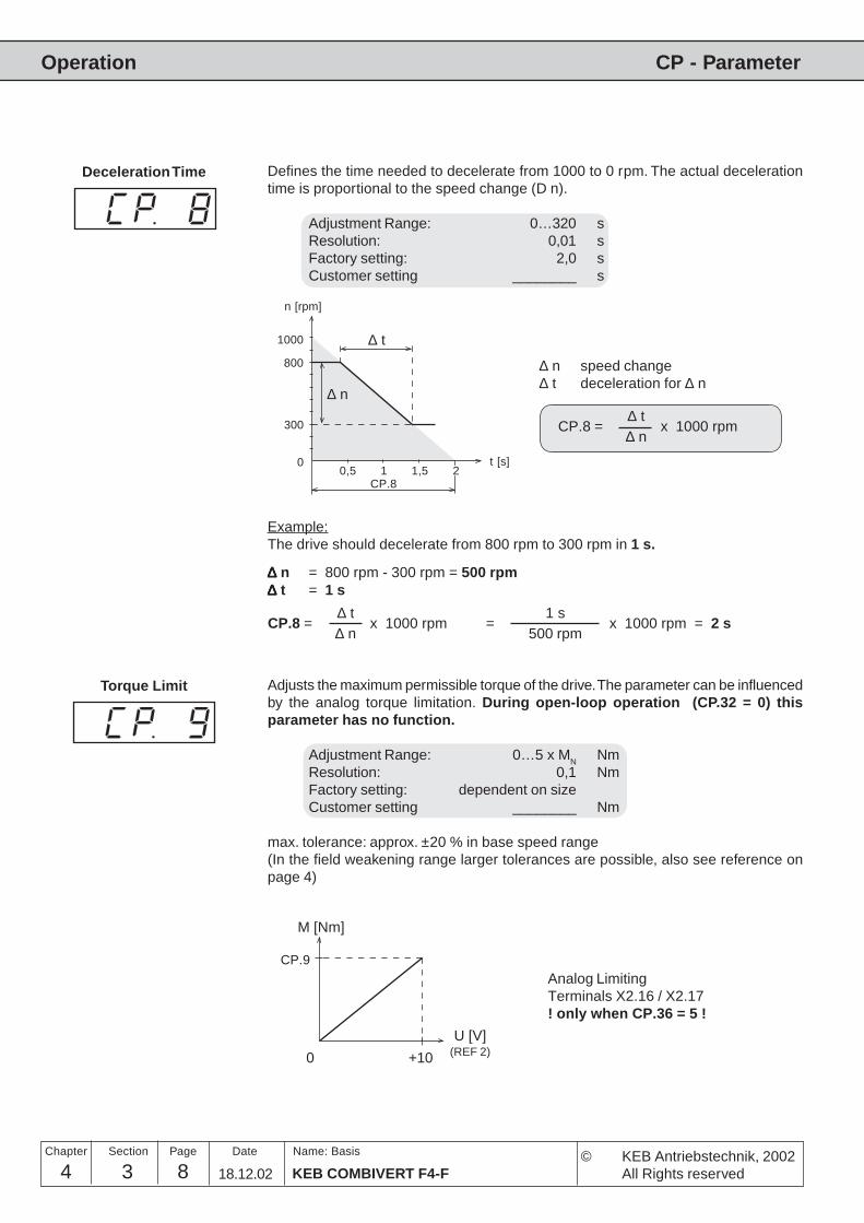
Defines the time needed to decelerate from 1000 to 0 rpm. The actual decelerationtime is proportional to the speed change (D n).
Adjustment Range: 0…320 sResolution: 0,01 sFactory setting: 2,0 sCustomer setting ________ s
Deceleration Time
∆ n speed change∆ t deceleration for ∆ n
∆ tCP.8 = x 1000 rpm
∆ n
Example:The drive should decelerate from 800 rpm to 300 rpm in 1 s.
∆∆∆∆∆ n = 800 rpm - 300 rpm = 500 rpm∆∆∆∆∆ t = 1 s
∆ t 1 sCP.8 = x 1000 rpm = x 1000 rpm = 2 s
∆ n 500 rpm
t [s]
CP.8
n [rpm]
1000
800
300
00,5 1 1,5 2
∆ t
∆ n
Torque Limit Adjusts the maximum permissible torque of the drive. The parameter can be influencedby the analog torque limitation. During open-loop operation (CP.32 = 0) thisparameter has no function.
Adjustment Range: 0…5 x MN
NmResolution: 0,1 NmFactory setting: dependent on sizeCustomer setting ________ Nm
max. tolerance: approx. ±20 % in base speed range(In the field weakening range larger tolerances are possible, also see reference onpage 4)
Analog LimitingTerminals X2.16 / X2.17! only when CP.36 = 5 !
CP.9
+100
M [Nm]
U [V](REF 2)
94 3 9KEB COMBIVERT F4-F
Name: Basis
18.12.02
4
CP - Parameter
© KEB Antriebstechnik, 2002All Rights reserved
Operation
Chapter Section PageDate
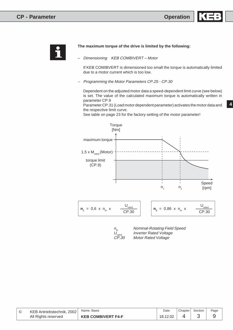
The maximum torque of the drive is limited by the following:
nfn Nominal-Rotating Field SpeedUrated Inverter Rated VoltageCP.30 Motor Rated Voltage
Uratedn1 = 0,6 x n
fn x
CP.30
Uratedn2 = 0,86 x n
fn x
CP.30
Torque[Nm]
Speed[rpm]n
1
torque limit(CP.9)
maximum torque
1,5 x Mrated
(Motor)
n2
– Dimensioning KEB COMBIVERT – Motor
If KEB COMIBVERT is dimensioned too small the torque is automatically limiteddue to a motor current which is too low.
– Programming the Motor Parameters CP.25 - CP.30
Dependent on the adjusted motor data a speed-dependent limit curve (see below)is set. The value of the calculated maximum torque is automatically written inparameter CP.9Parameter CP.31 (Load motor dependent parameter) activates the motor data andthe respective limit curve.See table on page 23 for the factory setting of the motor parameter!
4 3 KEB COMBIVERT F4-F10Name: Basis
18.12.02
CP - Parameter
© KEB Antriebstechnik, 2002All Rights reserved
Operation
Chapter Section Page Date
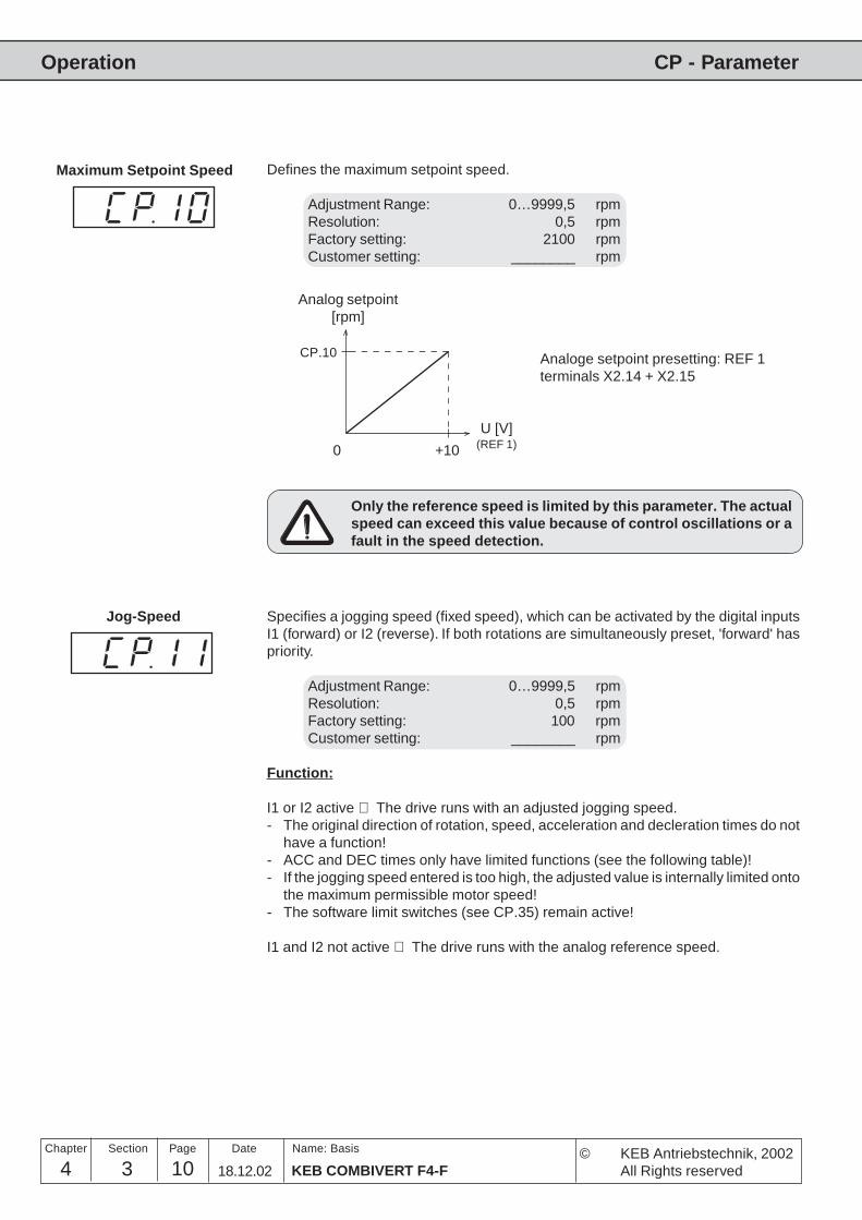
Defines the maximum setpoint speed.
Adjustment Range: 0…9999,5 rpmResolution: 0,5 rpmFactory setting: 2100 rpmCustomer setting: ________ rpm
Only the reference speed is limited by this parameter. The actualspeed can exceed this value because of control oscillations or afault in the speed detection.
Maximum Setpoint Speed
Analoge setpoint presetting: REF 1terminals X2.14 + X2.15
CP.10
+100
Analog setpoint[rpm]
U [V](REF 1)
Specifies a jogging speed (fixed speed), which can be activated by the digital inputsI1 (forward) or I2 (reverse). If both rotations are simultaneously preset, 'forward' haspriority.
Adjustment Range: 0…9999,5 rpmResolution: 0,5 rpmFactory setting: 100 rpmCustomer setting: ________ rpm
Function:
I1 or I2 active ⇒ The drive runs with an adjusted jogging speed.- The original direction of rotation, speed, acceleration and decleration times do not
have a function!- ACC and DEC times only have limited functions (see the following table)!- If the jogging speed entered is too high, the adjusted value is internally limited onto
the maximum permissible motor speed!- The software limit switches (see CP.35) remain active!
I1 and I2 not active ⇒ The drive runs with the analog reference speed.
Jog-Speed
114 3 11KEB COMBIVERT F4-F
Name: Basis
18.12.02
4
CP - Parameter
© KEB Antriebstechnik, 2002All Rights reserved
Operation
Chapter Section PageDate
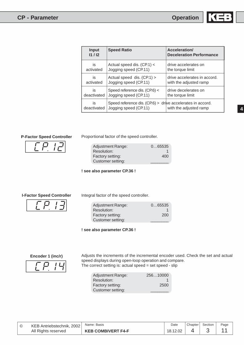
P-Factor Speed Controller Proportional factor of the speed controller.
Adjustment Range: 0…65535Resolution: 1Factory setting: 400Customer setting: ________
! see also parameter CP.36 !
I-Factor Speed Controller Integral factor of the speed controller.
Adjustment Range: 0…65535Resolution: 1Factory setting: 200Customer setting: ________
! see also parameter CP.36 !
Encoder 1 (inc/r) Adjusts the increments of the incremental encoder used. Check the set and actualspeed displays during open-loop operation and compare.The correct setting is: actual speed = set speed - slip
Adjustment Range: 256…10000Resolution: 1Factory setting: 2500Customer setting: ________
Input Speed Ratio Acceleration/I1 / I2 Deceleration Performance
is Actual speed dis. (CP.1) < drive accelerates onactivated Jogging speed (CP.11) the torque limit
is Actual speed dis. (CP.1) > drive accelerates in accord.activated Jogging speed (CP.11) with the adjusted ramp
is Speed reference dis. (CP.6) < drive decelerates ondeactivated Jogging speed (CP.11) the torque limit
is Speed reference dis. (CP.6) > drive accelerates in accord.deactivated Jogging speed (CP.11) with the adjusted ramp
4 3 KEB COMBIVERT F4-F12Name: Basis
18.12.02
CP - Parameter
© KEB Antriebstechnik, 2002All Rights reserved
Operation
Chapter Section Page Date
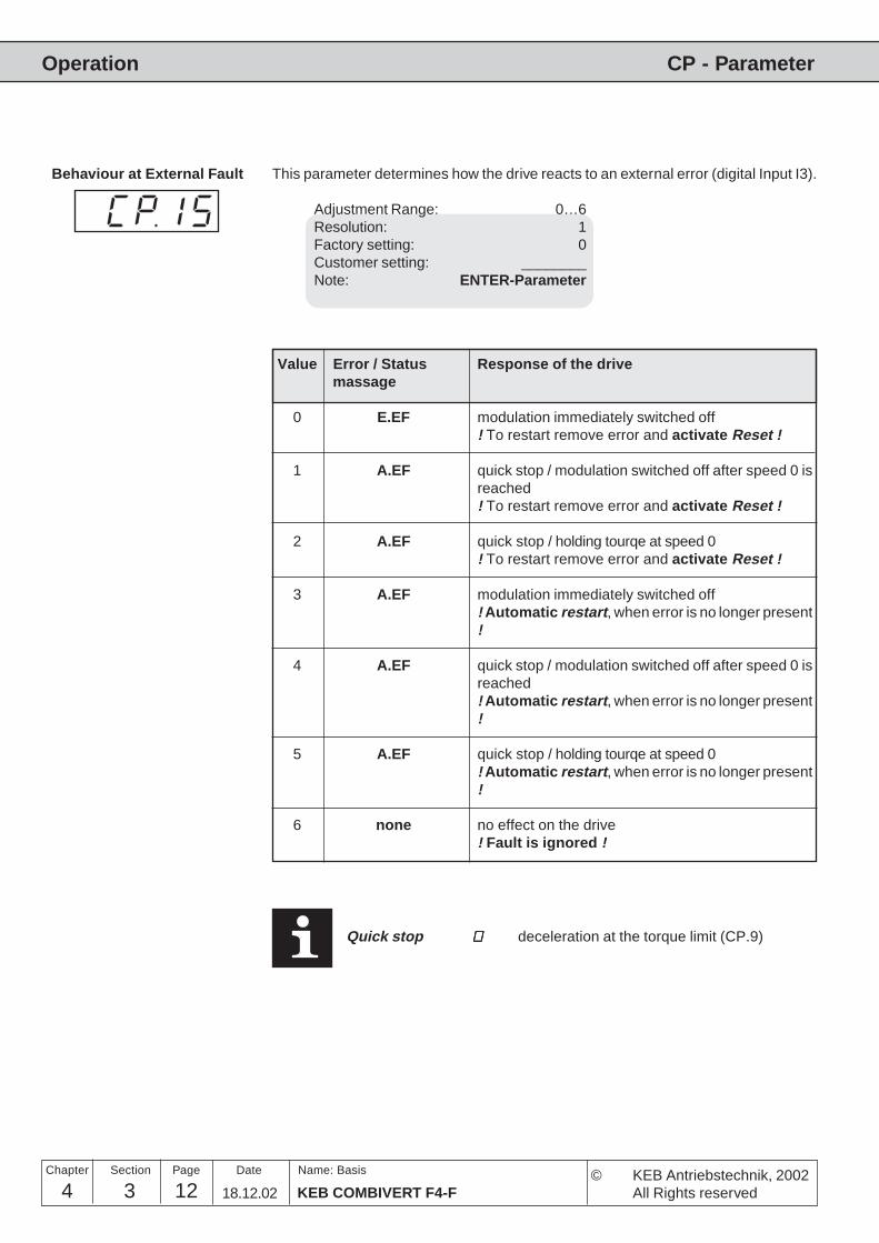
Value Error / Status Response of the drivemassage
0 E.EF modulation immediately switched off! To restart remove error and activate Reset !
1 A.EF quick stop / modulation switched off after speed 0 isreached! To restart remove error and activate Reset !
2 A.EF quick stop / holding tourqe at speed 0! To restart remove error and activate Reset !
3 A.EF modulation immediately switched off! Automatic restart, when error is no longer present!
4 A.EF quick stop / modulation switched off after speed 0 isreached! Automatic restart, when error is no longer present!
5 A.EF quick stop / holding tourqe at speed 0! Automatic restart, when error is no longer present!
6 none no effect on the drive! Fault is ignored !
Behaviour at External Fault This parameter determines how the drive reacts to an external error (digital Input I3).
Adjustment Range: 0…6Resolution: 1Factory setting: 0Customer setting: ________Note: ENTER-Parameter
Quick stop ⇒⇒⇒⇒⇒ deceleration at the torque limit (CP.9)

134 3 13KEB COMBIVERT F4-F
Name: Basis
18.12.02
4
CP - Parameter
© KEB Antriebstechnik, 2002All Rights reserved
Operation
Chapter Section PageDate
Offset REF 1 Makes it possible to shift the speed setpoint curve.
Adjustment Range: -100…+100 %Resolution: 0,1 %Factory setting: 0 %Customer setting: ________ %
Examples:
Curve 1: CP.16 = 0% (Standard adjustment)0V = 0 rpmDirection of rotation "forward": nmax is reached at +10VDirection of rotation "reverse": nmax is reached at -10 V
Curve 2: CP.16 = -40%0V = -40 % of nmax "forward"Direction of rotation "forward": nmax is reached at 60% of +10VDirection of rotation "reverse": maximum 60% of nmax possible
Curve 3: CP.16 = +70%0V = 70 % of nmax "reverse"Direction of rotation "forward": maximum 30% of nmax possibleDirection of rotation "reverse": nmax is reached at 30% of -10V
nmax
"reverse"
70 %
2) 1)
3)
-10 V
nmax
"forward"
-4 V
40 %
+10 V
+7 V
4 3 KEB COMBIVERT F4-F14Name: Basis
18.12.02
CP - Parameter
© KEB Antriebstechnik, 2002All Rights reserved
Operation
Chapter Section Page Date
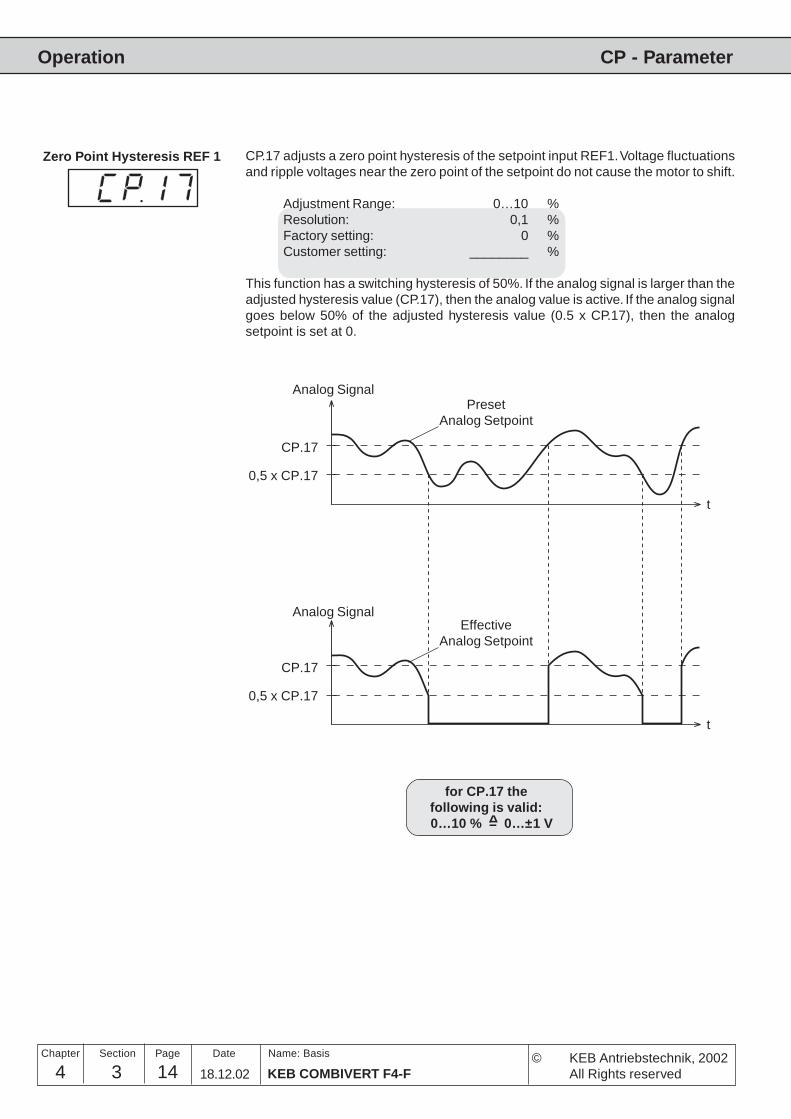
CP.17 adjusts a zero point hysteresis of the setpoint input REF1. Voltage fluctuationsand ripple voltages near the zero point of the setpoint do not cause the motor to shift.
Adjustment Range: 0…10 %Resolution: 0,1 %Factory setting: 0 %Customer setting: ________ %
This function has a switching hysteresis of 50%. If the analog signal is larger than theadjusted hysteresis value (CP.17), then the analog value is active. If the analog signalgoes below 50% of the adjusted hysteresis value (0.5 x CP.17), then the analogsetpoint is set at 0.
Zero Point Hysteresis REF 1
CP.17
0,5 x CP.17
Analog Signal
CP.17
0,5 x CP.17
t
t
Analog Signal
PresetAnalog Setpoint
EffectiveAnalog Setpoint
for CP.17 thefollowing is valid:
0…10 % = 0…±1 V^
154 3 15KEB COMBIVERT F4-F
Name: Basis
18.12.02
4
CP - Parameter
© KEB Antriebstechnik, 2002All Rights reserved
Operation
Chapter Section PageDate
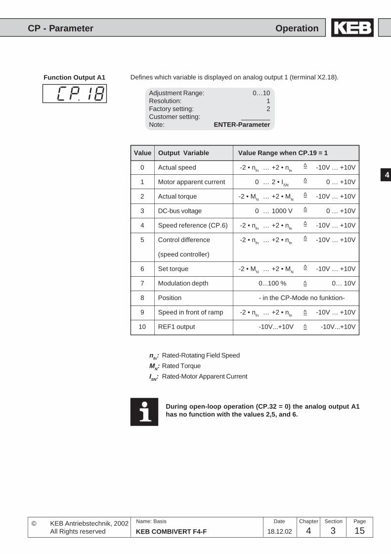
Value Output Variable Value Range when CP.19 = 1
0 Actual speed -2 • nfn
… +2 • nfn
= -10V … +10V
1 Motor apparent current 0 … 2 • ISN
= 0 … +10V
2 Actual torque -2 • MN
… +2 • MN
= -10V … +10V
3 DC-bus voltage 0 … 1000 V = 0 … +10V
4 Speed reference (CP.6) -2 • nfn
… +2 • nfn
= -10V … +10V
5 Control difference -2 • nfn
… +2 • nfn
= -10V … +10V
(speed controller)
6 Set torque -2 • MN
… +2 • MN
= -10V … +10V
7 Modulation depth 0...100 % = 0… 10V
8 Position - in the CP-Mode no funktion-
9 Speed in front of ramp -2 • nfn
… +2 • nfn = -10V … +10V
10 REF1 output -10V...+10V = -10V...+10V
Defines which variable is displayed on analog output 1 (terminal X2.18).
Adjustment Range: 0…10Resolution: 1Factory setting: 2Customer setting: ________Note: ENTER-Parameter
Function Output A1
^
^
^
^
^
^
^
During open-loop operation (CP.32 = 0) the analog output A1has no function with the values 2,5, and 6.
nfn: Rated-Rotating Field Speed
MN: Rated Torque
ISN: Rated-Motor Apparent Current
4 3 KEB COMBIVERT F4-F16Name: Basis
18.12.02
CP - Parameter
© KEB Antriebstechnik, 2002All Rights reserved
Operation
Chapter Section Page Date
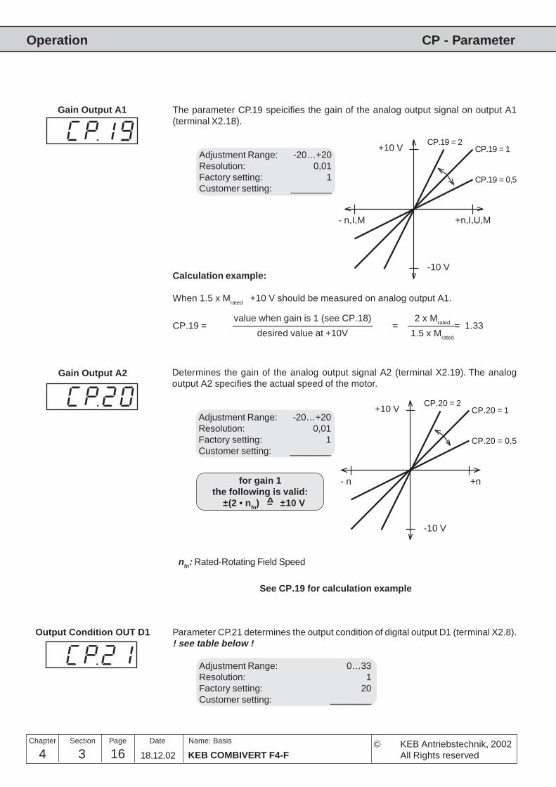
Calculation example:
When 1.5 x Mrated
+10 V should be measured on analog output A1.
value when gain is 1 (see CP.18) 2 x MratedCP.19 = ––––––––––––––––––––––––––– = –––––––––= 1.33
desired value at +10V 1.5 x Mrated
Gain Output A2 Determines the gain of the analog output signal A2 (terminal X2.19). The analogoutput A2 specifies the actual speed of the motor.
Adjustment Range: -20…+20Resolution: 0,01Factory setting: 1Customer setting: ________
Output Condition OUT D1 Parameter CP.21 determines the output condition of digital output D1 (terminal X2.8).! see table below !
Adjustment Range: 0…33Resolution: 1Factory setting: 20Customer setting: ________
The parameter CP.19 speicifies the gain of the analog output signal on output A1(terminal X2.18).
Adjustment Range: -20…+20Resolution: 0,01Factory setting: 1Customer setting: ________
Gain Output A1
See CP.19 for calculation example
for gain 1the following is valid: ±(2 • nfn) = ±10 V^
nfn: Rated-Rotating Field Speed
CP.19 = 1
+n,I,U,M
+10 V
- n,I,M
-10 V
CP.19 = 2
CP.19 = 0,5
CP.20 = 1
+n
+10 V
- n
-10 V
CP.20 = 2
CP.20 = 0,5
174 3 17KEB COMBIVERT F4-F
Name: Basis
18.12.02
4
CP - Parameter
© KEB Antriebstechnik, 2002All Rights reserved
Operation
Chapter Section PageDate
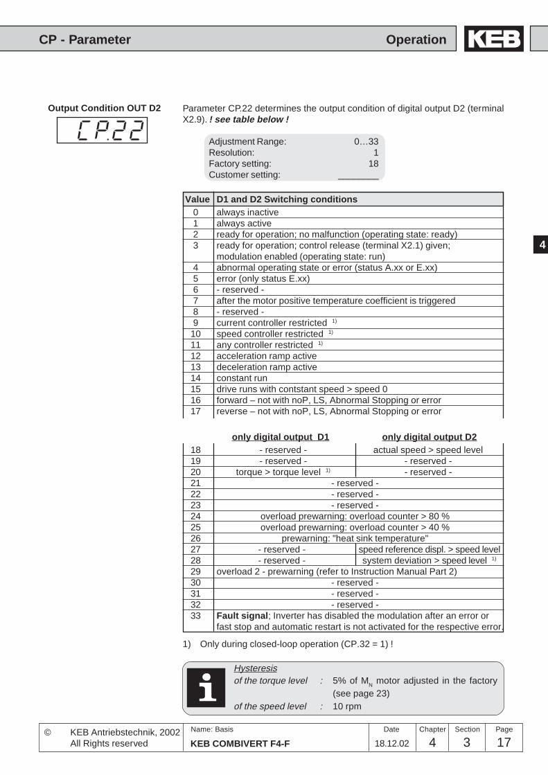
Output Condition OUT D2
1) Only during closed-loop operation (CP.32 = 1) !
Hysteresisof the torque level : 5% of M
N motor adjusted in the factory
(see page 23)of the speed level : 10 rpm
Parameter CP.22 determines the output condition of digital output D2 (terminalX2.9). ! see table below !
Adjustment Range: 0…33Resolution: 1Factory setting: 18Customer setting: ________
Value D1 and D2 Switching conditions0 always inactive1 always active2 ready for operation; no malfunction (operating state: ready)3 ready for operation; control release (terminal X2.1) given;
modulation enabled (operating state: run)4 abnormal operating state or error (status A.xx or E.xx)5 error (only status E.xx)6 - reserved -7 after the motor positive temperature coefficient is triggered8 - reserved -9 current controller restricted 1)
10 speed controller restricted 1)
11 any controller restricted 1)
12 acceleration ramp active13 deceleration ramp active14 constant run15 drive runs with contstant speed > speed 016 forward – not with noP, LS, Abnormal Stopping or error17 reverse – not with noP, LS, Abnormal Stopping or error
only digital output D1 only digital output D218 - reserved - actual speed > speed level19 - reserved - - reserved -20 torque > torque level 1) - reserved -21 - reserved -22 - reserved -23 - reserved -24 overload prewarning: overload counter > 80 %25 overload prewarning: overload counter > 40 %26 prewarning: "heat sink temperature"27 - reserved - speed reference displ. > speed level28 - reserved - system deviation > speed level 1)
29 overload 2 - prewarning (refer to Instruction Manual Part 2)30 - reserved -31 - reserved -32 - reserved -33 Fault signal; Inverter has disabled the modulation after an error or
fast stop and automatic restart is not activated for the respective error.
4 3 KEB COMBIVERT F4-F18Name: Basis
18.12.02
CP - Parameter
© KEB Antriebstechnik, 2002All Rights reserved
Operation
Chapter Section Page Date
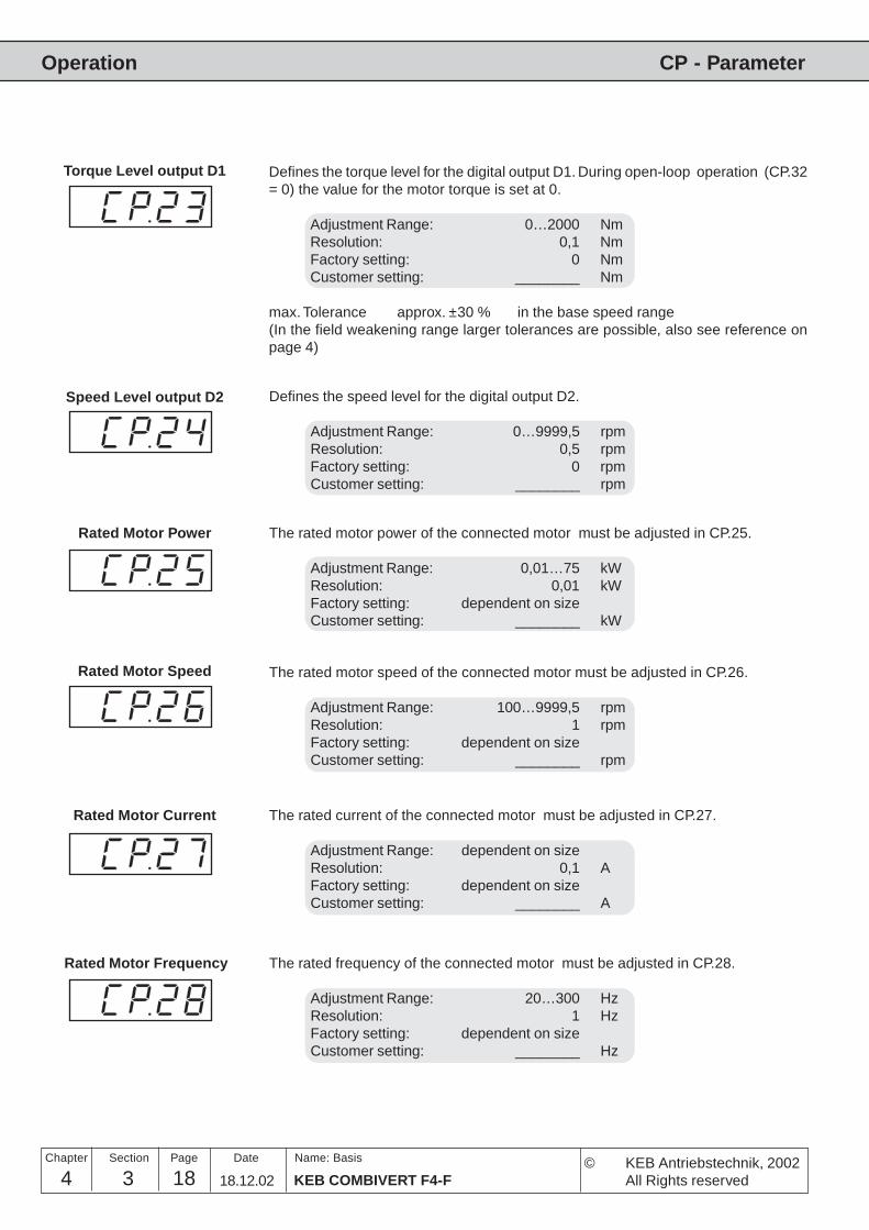
Defines the torque level for the digital output D1. During open-loop operation (CP.32= 0) the value for the motor torque is set at 0.
Adjustment Range: 0…2000 NmResolution: 0,1 NmFactory setting: 0 NmCustomer setting: ________ Nm
max. Tolerance approx. ±30 % in the base speed range(In the field weakening range larger tolerances are possible, also see reference onpage 4)
Torque Level output D1
The rated motor speed of the connected motor must be adjusted in CP.26.
Adjustment Range: 100…9999,5 rpmResolution: 1 rpmFactory setting: dependent on sizeCustomer setting: ________ rpm
The rated current of the connected motor must be adjusted in CP.27.
Adjustment Range: dependent on sizeResolution: 0,1 AFactory setting: dependent on sizeCustomer setting: ________ A
Speed Level output D2 Defines the speed level for the digital output D2.
Adjustment Range: 0…9999,5 rpmResolution: 0,5 rpmFactory setting: 0 rpmCustomer setting: ________ rpm
Rated Motor Power The rated motor power of the connected motor must be adjusted in CP.25.
Adjustment Range: 0,01…75 kWResolution: 0,01 kWFactory setting: dependent on sizeCustomer setting: ________ kW
Rated Motor Speed
Rated Motor Current
The rated frequency of the connected motor must be adjusted in CP.28.
Adjustment Range: 20…300 HzResolution: 1 HzFactory setting: dependent on sizeCustomer setting: ________ Hz
Rated Motor Frequency

194 3 19KEB COMBIVERT F4-F
Name: Basis
18.12.02
4
CP - Parameter
© KEB Antriebstechnik, 2002All Rights reserved
Operation
Chapter Section PageDate
The rated power factor of the connected motor must be adjusted in CP.29.
Adjustment Range: 0,05…1Resolution: 0,01Factory setting: dependent on sizeCustomer setting: ________
The rated voltage of the connected motor must be adjusted in CP.30.
Adjustment Range: 100…500 VResolution: 1 VFactory setting: 400 VCustomer setting: ________ V
Rated Motor cos (Phi)
Rated Motor Voltage
Load motor dependentparameter
The basic settings of the inverter correspond to the size of the unit and the respectivemotor (see table on page GB 35). If the motor data in CP.25...30 are changed, thenCP.31 must be activated once. This re-adjusts the current controller, torque curveand torque limit. With this the torque limit is set at the value, that is maximally possiblein the speed range (dependent on inverter rated current).
Value Meaning1 Pre-adjustment of the motor-dependent control-parameters
The adjusted voltage stabilization value or the voltage class of theinverter is taken as input voltage.
2 Pre-adjustment of the motor-dependent control-parametersThe DC-link voltage /√2 measured at switch on is taken as input voltage.
The pre-adjustments made at value 1 or 2 refer to the same parameters.For CP.31=2 the inverter measures automatically the input voltage which is requiredas reference value for the calculation.
Adjustment Range: 0…2Resolution: 1Werkseinstellung: 0Customer setting: ________
When control release is active the adjustment was not completed."nco" appears in the display!
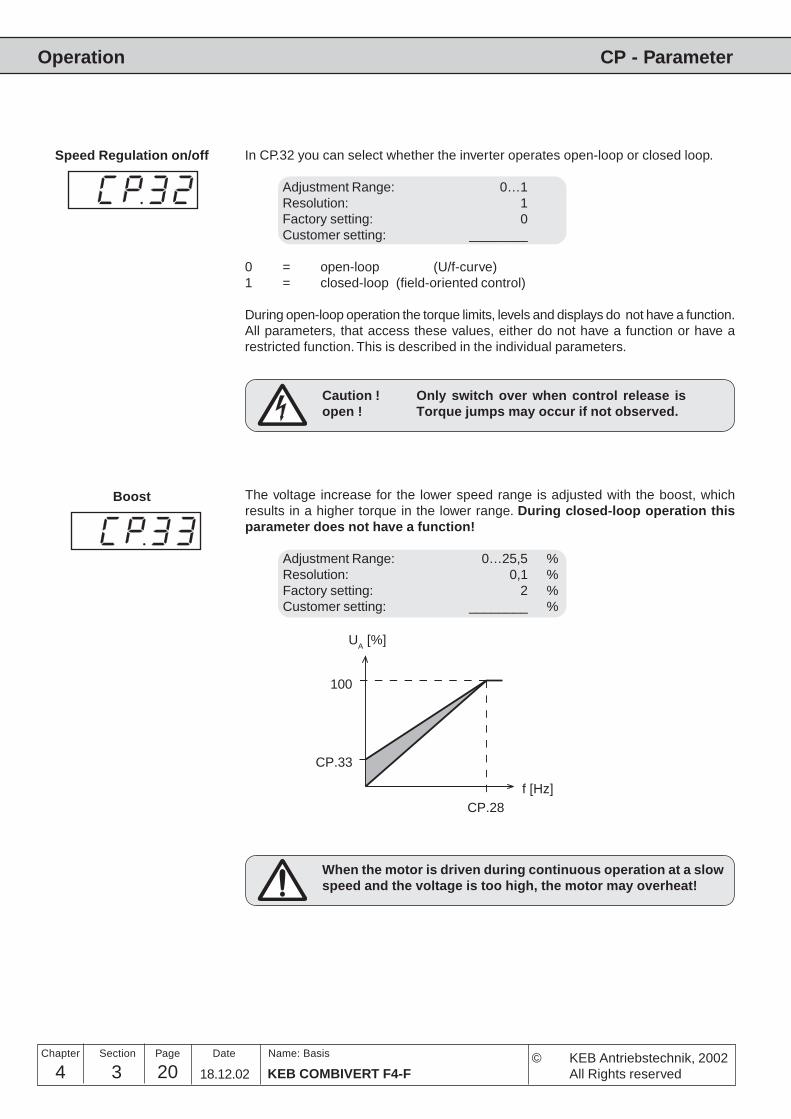
4 3 KEB COMBIVERT F4-F20Name: Basis
18.12.02
CP - Parameter
© KEB Antriebstechnik, 2002All Rights reserved
Operation
Chapter Section Page Date
In CP.32 you can select whether the inverter operates open-loop or closed loop.
Adjustment Range: 0…1Resolution: 1Factory setting: 0Customer setting: ________
0 = open-loop (U/f-curve)1 = closed-loop (field-oriented control)
During open-loop operation the torque limits, levels and displays do not have a function.All parameters, that access these values, either do not have a function or have arestricted function. This is described in the individual parameters.
Speed Regulation on/off
Boost The voltage increase for the lower speed range is adjusted with the boost, whichresults in a higher torque in the lower range. During closed-loop operation thisparameter does not have a function!
Adjustment Range: 0…25,5 %Resolution: 0,1 %Factory setting: 2 %Customer setting: ________ %
Caution ! Only switch over when control release isopen ! Torque jumps may occur if not observed.
100
CP.33
f [Hz]CP.28
UA [%]
When the motor is driven during continuous operation at a slowspeed and the voltage is too high, the motor may overheat!
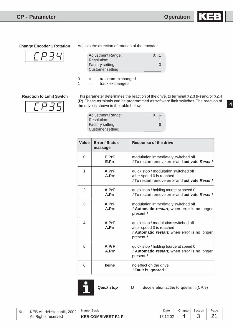
214 3 21KEB COMBIVERT F4-F
Name: Basis
18.12.02
4
CP - Parameter
© KEB Antriebstechnik, 2002All Rights reserved
Operation
Chapter Section PageDate
Adjusts the direction of rotation of the encoder.
Adjustment Range: 0…1Resolution: 1Factory setting: 0Customer setting ________
0 = track not exchanged1 = track exchanged
Change Encoder 1 Rotation
This parameter determines the reaction of the drive, to terminal X2.3 (F) and/or X2.4(R). These terminals can be programmed as software limit switches. The reaction ofthe drive is shown in the table below.
Adjustment Range: 0…6Resolution: 1Factory setting: 6Customer setting: ________
Reaction to Limit Switch
Value Error / Status Response of the drivemassage
0 E.PrF modulation immediately switched offE.Prr ! To restart remove error and activate Reset !
1 A.PrF quick stop / modulation switched offA.Prr after speed 0 is reached
! To restart remove error and activate Reset !
2 A.PrF quick stop / holding tourqe at speed 0A.Prr ! To restart remove error and activate Reset !
3 A.PrF modulation immediately switched offA.Prr ! Automatic restart, when error is no longer
present !
4 A.PrF quick stop / modulation switched offA.Prr after speed 0 is reached
! Automatic restart, when error is no longerpresent !
5 A.PrF quick stop / holding tourqe at speed 0A.Prr ! Automatic restart, when error is no longer
present !
6 keine no effect on the drive! Fault is ignored !
Quick stop ⇒⇒⇒⇒⇒ deceleration at the torque limit (CP.9)
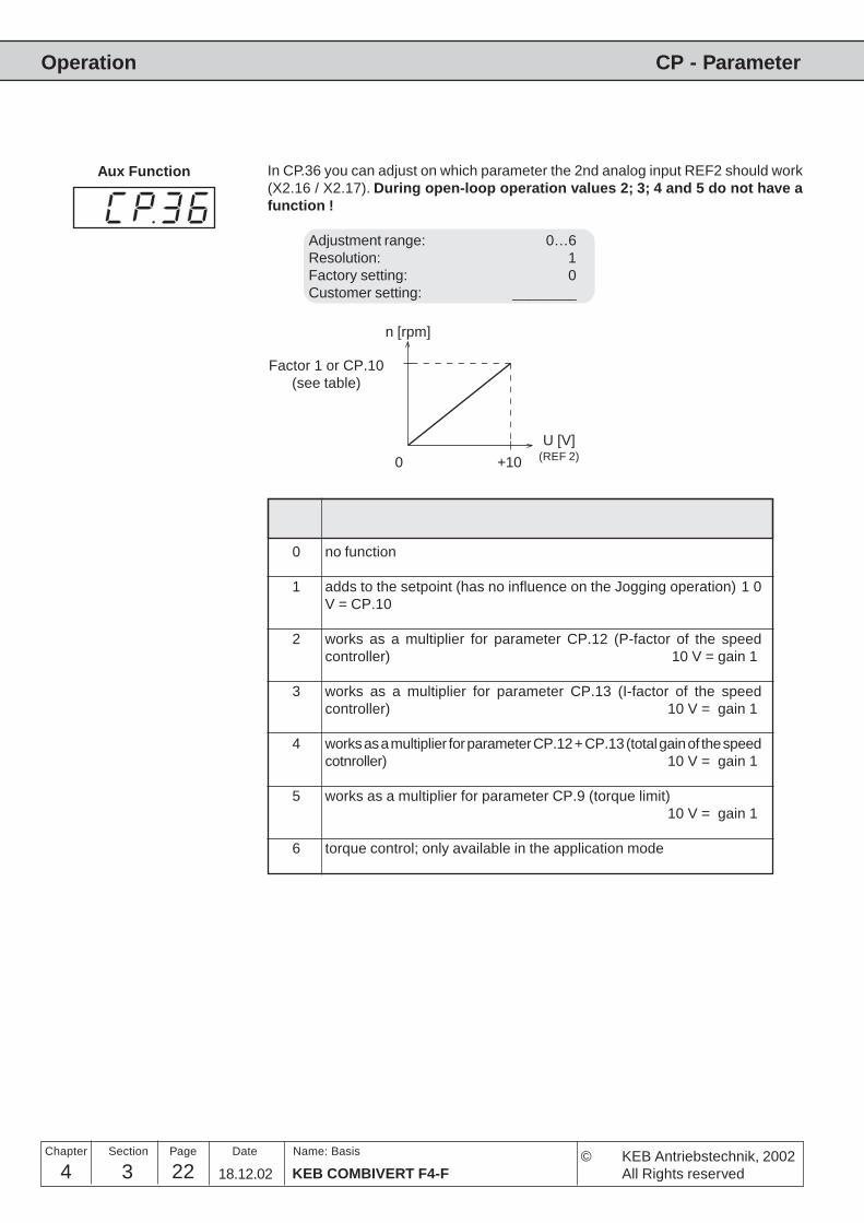
4 3 KEB COMBIVERT F4-F22Name: Basis
18.12.02
CP - Parameter
© KEB Antriebstechnik, 2002All Rights reserved
Operation
Chapter Section Page Date
Value Function Analog Input REF2
0 no function
1 adds to the setpoint (has no influence on the Jogging operation) 1 0V = CP.10
2 works as a multiplier for parameter CP.12 (P-factor of the speedcontroller) 10 V = gain 1
3 works as a multiplier for parameter CP.13 (I-factor of the speedcontroller) 10 V = gain 1
4 works as a multiplier for parameter CP.12 + CP.13 (total gain of the speedcotnroller) 10 V = gain 1
5 works as a multiplier for parameter CP.9 (torque limit)10 V = gain 1
6 torque control; only available in the application mode
In CP.36 you can adjust on which parameter the 2nd analog input REF2 should work(X2.16 / X2.17). During open-loop operation values 2; 3; 4 and 5 do not have afunction !
Adjustment range: 0…6Resolution: 1Factory setting: 0Customer setting: ________
Aux Function
Factor 1 or CP.10(see table)
+100
n [rpm]
U [V](REF 2)
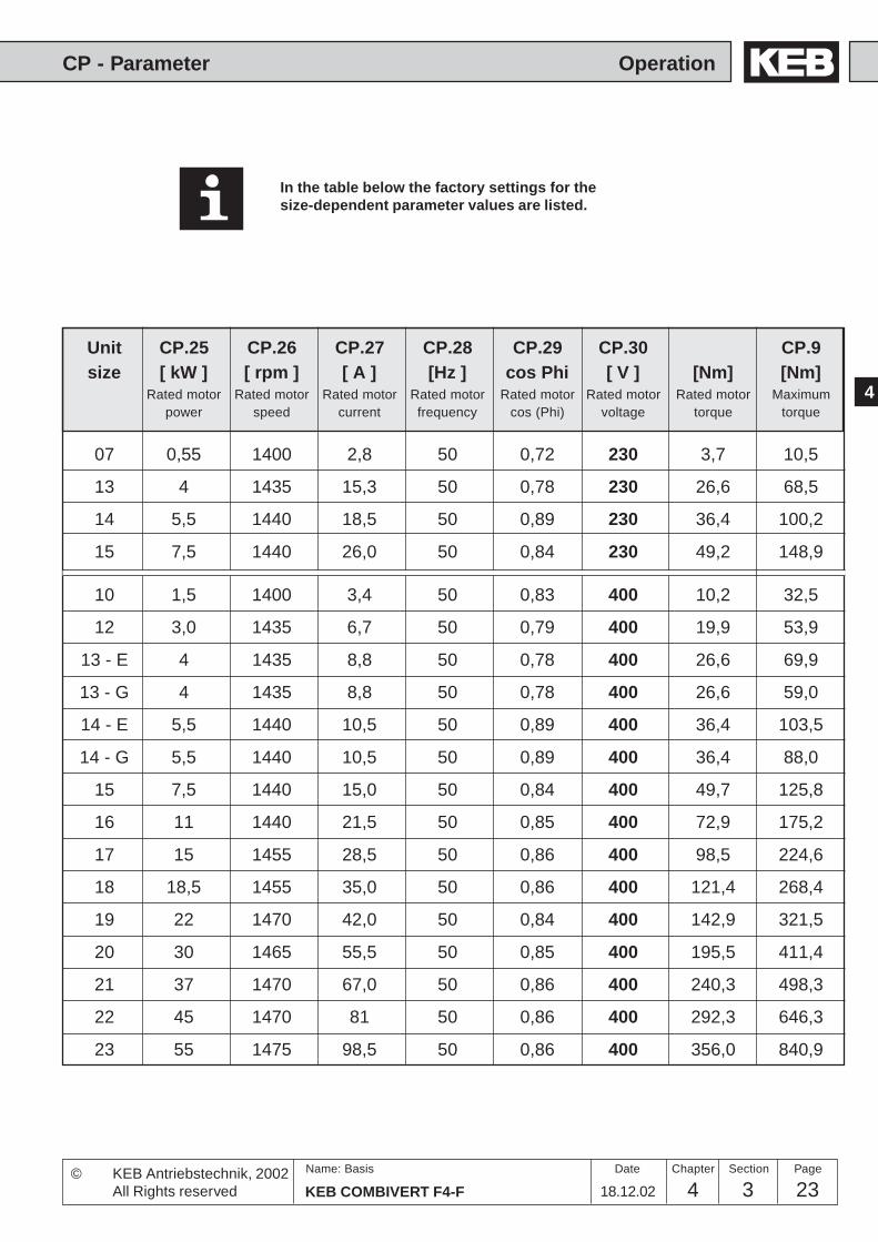
234 3 23KEB COMBIVERT F4-F
Name: Basis
18.12.02
4
CP - Parameter
© KEB Antriebstechnik, 2002All Rights reserved
Operation
Chapter Section PageDate
In the table below the factory settings for thesize-dependent parameter values are listed.
Unit CP.25 CP.26 CP.27 CP.28 CP.29 CP.30 CP.9size [ kW ] [ rpm ] [ A ] [Hz ] cos Phi [ V ] [Nm] [Nm]
Rated motor Rated motor Rated motor Rated motor Rated motor Rated motor Rated motor Maximumpower speed current frequency cos (Phi) voltage torque torque
07 0,55 1400 2,8 50 0,72 230 3,7 10,5
13 4 1435 15,3 50 0,78 230 26,6 68,5
14 5,5 1440 18,5 50 0,89 230 36,4 100,2
15 7,5 1440 26,0 50 0,84 230 49,2 148,9
10 1,5 1400 3,4 50 0,83 400 10,2 32,5
12 3,0 1435 6,7 50 0,79 400 19,9 53,9
13 - E 4 1435 8,8 50 0,78 400 26,6 69,9
13 - G 4 1435 8,8 50 0,78 400 26,6 59,0
14 - E 5,5 1440 10,5 50 0,89 400 36,4 103,5
14 - G 5,5 1440 10,5 50 0,89 400 36,4 88,0
15 7,5 1440 15,0 50 0,84 400 49,7 125,8
16 11 1440 21,5 50 0,85 400 72,9 175,2
17 15 1455 28,5 50 0,86 400 98,5 224,6
18 18,5 1455 35,0 50 0,86 400 121,4 268,4
19 22 1470 42,0 50 0,84 400 142,9 321,5
20 30 1465 55,5 50 0,85 400 195,5 411,4
21 37 1470 67,0 50 0,86 400 240,3 498,3
22 45 1470 81 50 0,86 400 292,3 646,3
23 55 1475 98,5 50 0,86 400 356,0 840,9

4 3 KEB COMBIVERT F4-F24Name: Basis
18.12.02
CP - Parameter
© KEB Antriebstechnik, 2002All Rights reserved
Operation
Chapter Section Page Date
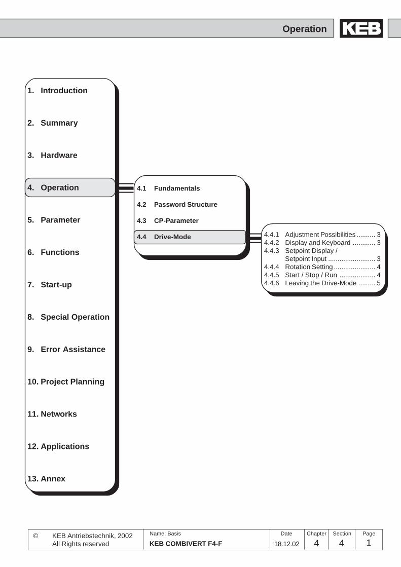
4 4 1KEB COMBIVERT F4-F
Name: Basis
18.12.02
1. Introduction
2. Summary
3. Hardware
4. Operation
5. Parameter
6. Functions
7. Start-up
8. Special Operation
9. Error Assistance
10. Project Planning
11. Networks
12. Applications
13. Annex
4.1 Fundamentals
4.2 Password Structure
4.3 CP-Parameter
4.4 Drive-Mode
Operation
© KEB Antriebstechnik, 2002All Rights reserved
Chapter Section PageDate
4.4.1 Adjustment Possibilities .......... 34.4.2 Display and Keyboard ............ 34.4.3 Setpoint Display /
Setpoint Input ......................... 34.4.4 Rotation Setting ...................... 44.4.5 Start / Stop / Run ................... 44.4.6 Leaving the Drive-Mode ......... 5

4 4 KEB COMBIVERT F4-F2Name: Basis
18.12.02
Operation Drive-Mode
© KEB Antriebstechnik, 2002All Rights reserved
Chapter Section Page Date
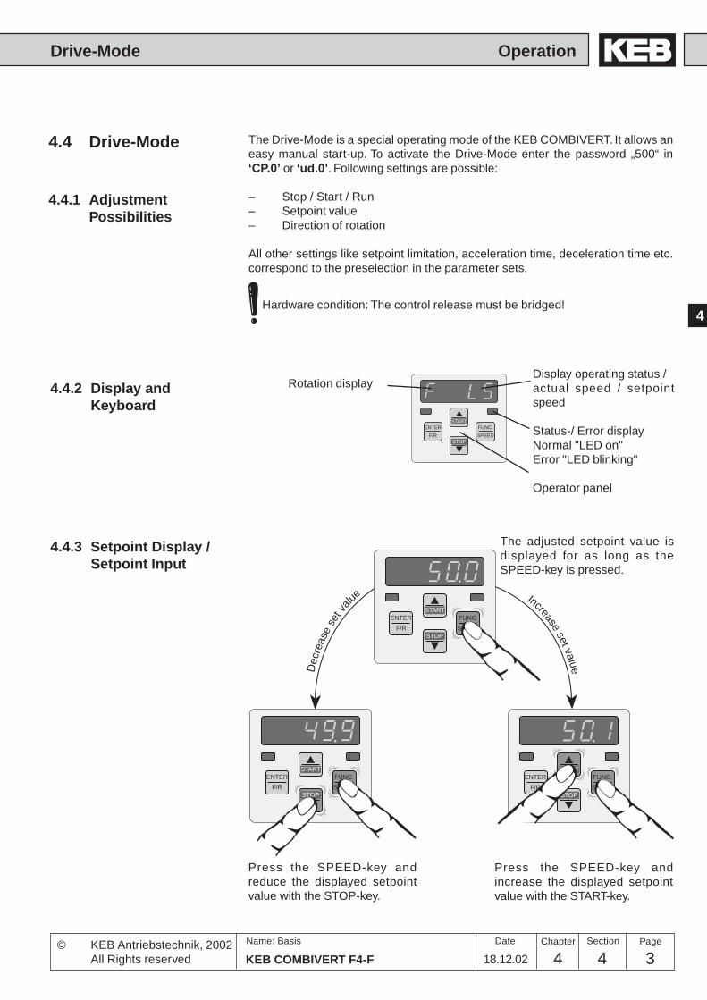
34 4 3KEB COMBIVERT F4-F
Name: Basis
18.12.02
4
OperationDrive-Mode
© KEB Antriebstechnik, 2002All Rights reserved
Section PageDate Chapter
START
STOP
FUNC.
SPEED
ENTER
F/R
The Drive-Mode is a special operating mode of the KEB COMBIVERT. It allows aneasy manual start-up. To activate the Drive-Mode enter the password „500“ in‘CP.0’ or ‘ud.0’. Following settings are possible:
– Stop / Start / Run– Setpoint value– Direction of rotation
All other settings like setpoint limitation, acceleration time, deceleration time etc.correspond to the preselection in the parameter sets.
Hardware condition: The control release must be bridged!
4.4 Drive-Mode
4.4.3 Setpoint Display /Setpoint Input
Rotation displayDisplay operating status /actual speed / setpointspeed
Status-/ Error displayNormal "LED on"Error "LED blinking"
Operator panel
4.4.1 AdjustmentPossibilities
Press the SPEED-key andreduce the displayed setpointvalue with the STOP-key.
Press the SPEED-key andincrease the displayed setpointvalue with the START-key.
The adjusted setpoint value isdisplayed for as long as theSPEED-key is pressed.
4.4.2 Display andKeyboard
Dec
reas
ese
t valu
e Increaseset value
START
STOP
FUNC.
SPEED
ENTER
F/R
START
STOP
FUNC.
SPEED
ENTER
F/R
STARTFUNC.
SPEED
ENTER
F/RSTOP
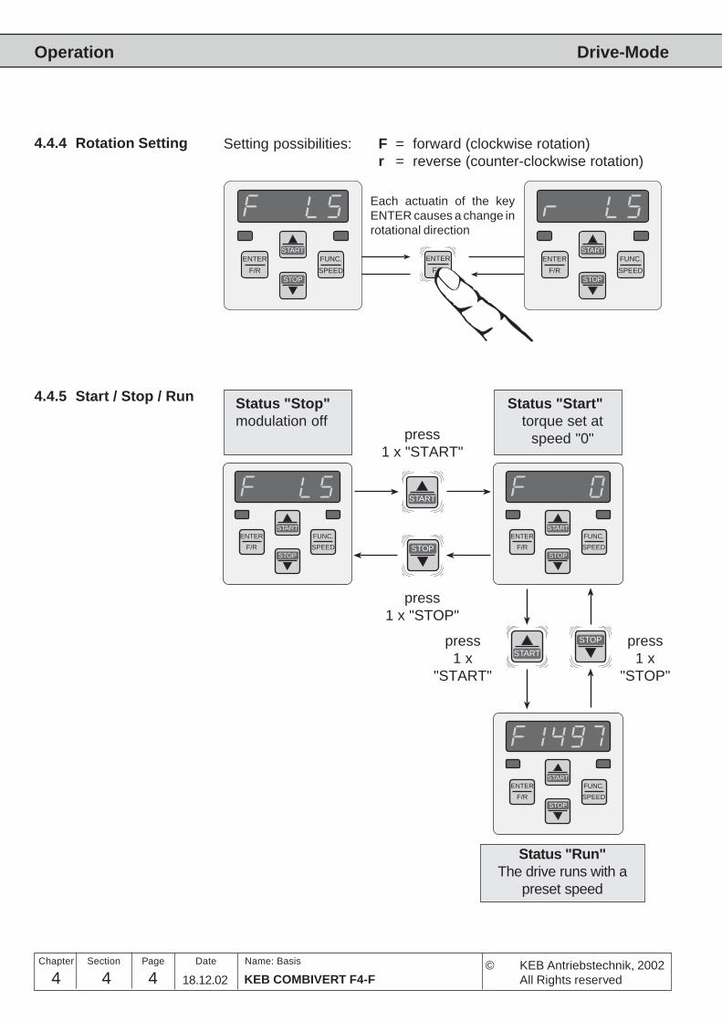
4 4 KEB COMBIVERT F4-F4Name: Basis
18.12.02
Operation Drive-Mode
© KEB Antriebstechnik, 2002All Rights reserved
Chapter Section Page Date
START
STOP
FUNC.
SPEED
ENTER
F/R
START
STOP
START
STOP
START
STOP
FUNC.
SPEED
ENTER
F/R
START
STOP
FUNC.
SPEED
ENTER
F/R
Status "Start"torque set at
speed "0"press1 x "START"
Status "Run"The drive runs with a
preset speed
Status "Stop"modulation off
press1 x "STOP"
press1 x
"STOP"
press1 x
"START"
4.4.4 Rotation Setting Setting possibilities: F = forward (clockwise rotation)r = reverse (counter-clockwise rotation)
Each actuatin of the keyENTER causes a change inrotational direction
START
STOP
FUNC.
SPEED
ENTER
F/R
START
STOP
FUNC.
SPEED
ENTER
F/R
ENTER
F/R
4.4.5 Start / Stop / Run
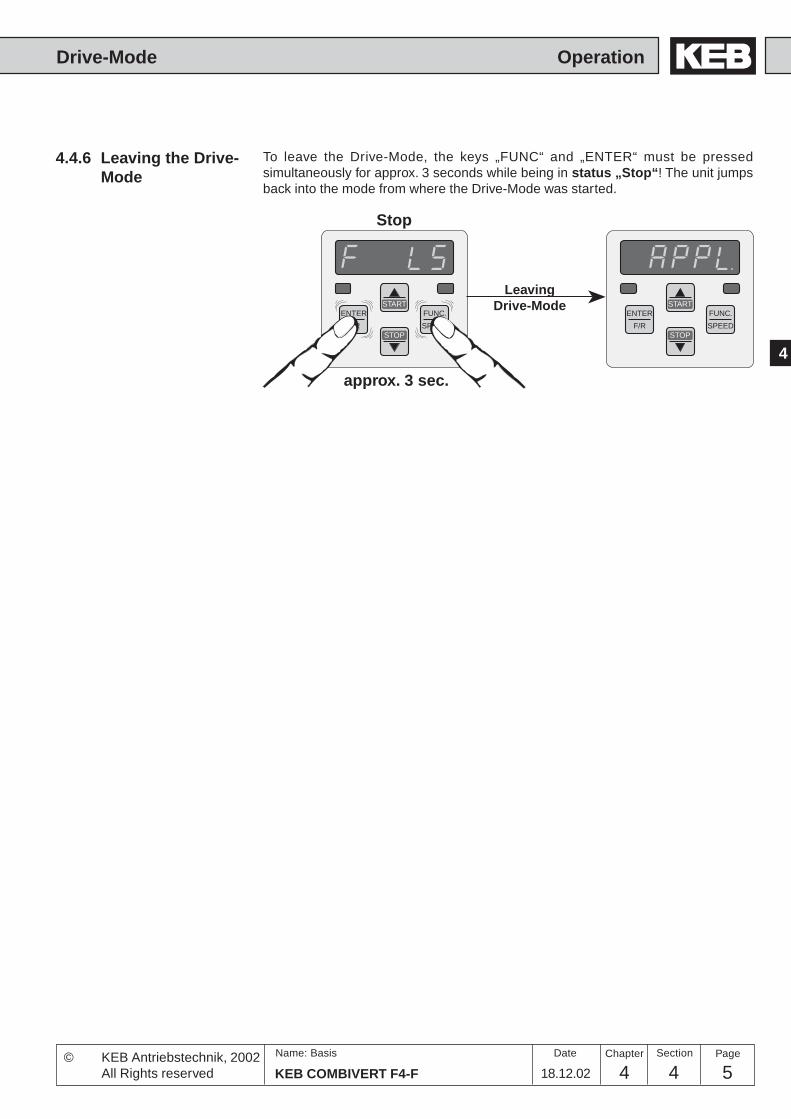
54 4 5KEB COMBIVERT F4-F
Name: Basis
18.12.02
4
OperationDrive-Mode
© KEB Antriebstechnik, 2002All Rights reserved
Section PageDate Chapter
To leave the Drive-Mode, the keys „FUNC“ and „ENTER“ must be pressedsimultaneously for approx. 3 seconds while being in status „Stop“! The unit jumpsback into the mode from where the Drive-Mode was started.
4.4.6 Leaving the Drive-Mode
START
STOP
FUNC.
SPEED
ENTER
F/R
START
STOP
FUNC.
SPEED
ENTER
F/R
approx. 3 sec.
Stop
LeavingDrive-Mode

4 4 KEB COMBIVERT F4-F6Name: Basis
18.12.02
Operation Drive-Mode
© KEB Antriebstechnik, 2002All Rights reserved
Chapter Section Page Date
Parameter
5 1 1KEB COMBIVERT F4-F
Name: Basis Section PageDate© KEB Antriebstechnik, 2002All Rights reserved
Chapter
31.10.02
1. Introduction
2. Summary
3. Hardware
4. Operation
5. Parameter
6. Functions
7. Start-up
8. Special Operation
9. Error Assistance
10. Project Planning
11. Networks
12. Applications
13. Annex
5.1 Parameter 5.1.1 Parameter Groups ................... 35.1.2 Parameter Listing F4-F ........... 5

Parameter
5 1 KEB COMBIVERT F4-F2Name: BasisChapter Section Page Date © KEB Antriebstechnik, 2002
All Rights reserved31.10.02
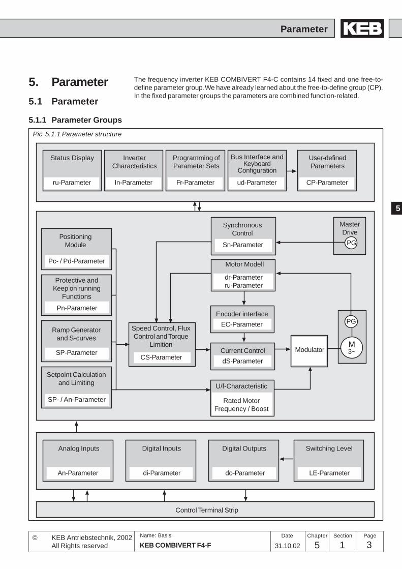
3
5
Parameter
5 1 3KEB COMBIVERT F4-F
Name: Basis Section PageDate© KEB Antriebstechnik, 2002All Rights reserved
Chapter
31.10.02
5.1.1 Parameter Groups
5.1 Parameter
The frequency inverter KEB COMBIVERT F4-C contains 14 fixed and one free-to-define parameter group. We have already learned about the free-to-define group (CP).In the fixed parameter groups the parameters are combined function-related.
5. Parameter
Pic. 5.1.1 Parameter structure
Status Display InverterCharacteristics
Programming ofParameter Sets
Bus Interface andKeyboard
Configuration
User-definedParameters
Control Terminal Strip
Analog Inputs Digital Inputs Digital Outputs Switching Level
Setpoint Calculationand Limiting
Protective andKeep on running
Functions
Ramp Generatorand S-curves
Speed Control, FluxControl and Torque
Limition
Rated MotorFrequency / Boost
U/f-Characteristic
Current Control
Motor Modell
Modulator
SynchronousControl
MasterDrive
PG
M3~
PG
ru-Parameter In-Parameter Fr-Parameter ud-Parameter CP-Parameter
An-Parameter di-Parameter do-Parameter LE-Parameter
SP- / An-Parameter
Pn-Parameter
SP-ParameterCS-Parameter dS-Parameter
dr-Parameterru-Parameter
Sn-ParameterPositioning
Module
Pc- / Pd-Parameter
Encoder interface
EC-Parameter

Parameter
5 1 KEB COMBIVERT F4-F4Name: BasisChapter Section Page Date © KEB Antriebstechnik, 2002
All Rights reserved31.10.02
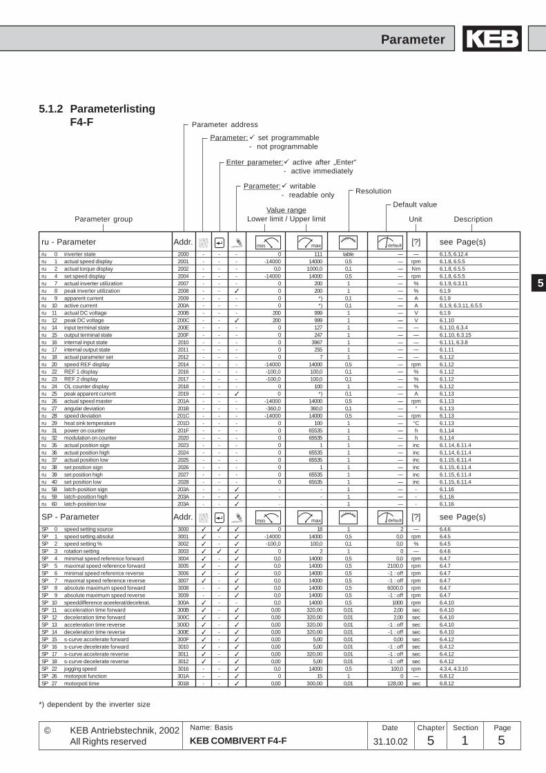
5
5
Parameter
5 1 5KEB COMBIVERT F4-F
Name: Basis Section PageDate© KEB Antriebstechnik, 2002All Rights reserved
Chapter
31.10.02
ru - Parameter Addr. min max default [?] see Page(s)ru 0 inverter state 2000 - - - 0 111 table –– –– 6.1.5, 6.12.4ru 1 actual speed display 2001 - - - -14000 14000 0,5 –– rpm 6.1.8, 6.5.5ru 2 actual torque display 2002 - - - 0,0 1000,0 0,1 –– Nm 6.1.8, 6.5.5ru 4 set speed display 2004 - - - -14000 14000 0,5 –– rpm 6.1.8, 6.5.5ru 7 actual inverter utilization 2007 - - - 0 200 1 –– % 6.1.9, 6.3.11ru 8 peak inverter utilization 2008 - - 0 200 1 –– % 6.1.9ru 9 apparent current 2009 - - - 0 *) 0,1 –– A 6.1.9ru 10 active current 200A - - - 0 *) 0,1 –– A 6.1.9, 6.3.11, 6.5.5ru 11 actual DC voltage 200B - - - 200 999 1 –– V 6.1.9ru 12 peak DC voltage 200C - - 200 999 1 –– V 6.1.10ru 14 input terminal state 200E - - - 0 127 1 –– –– 6.1.10, 6.3.4ru 15 output terminal state 200F - - - 0 247 1 –– –– 6.1.10, 6.3.15ru 16 internal input state 2010 - - - 0 3967 1 –– –– 6.1.11, 6.3.8ru 17 internal output state 2011 - - - 0 255 1 –– –– 6.1.11ru 18 actual parameter set 2012 - - - 0 7 1 –– –– 6.1.12ru 20 speed REF display 2014 - - - -14000 14000 0,5 –– rpm 6.1.12ru 22 REF 1 display 2016 - - - -100,0 100,0 0,1 –– % 6.1.12ru 23 REF 2 display 2017 - - - -100,0 100,0 0,1 –– % 6.1.12ru 24 OL counter display 2018 - - - 0 100 1 –– % 6.1.12ru 25 peak apparent current 2019 - - 0 *) 0,1 –– A 6.1.13ru 26 actual speed master 201A - - - -14000 14000 0,5 –– rpm 6.1.13ru 27 angular deviation 201B - - - -360,0 360,0 0,1 –– ° 6.1.13ru 28 speed deviation 201C - - - -14000 14000 0,5 –– rpm 6.1.13ru 29 heat sink temperature 201D - - - 0 100 1 –– °C 6.1.13ru 31 power on counter 201F - - - 0 65535 1 –– h 6.1.14ru 32 modulation on counter 2020 - - - 0 65535 1 –– h 6.1.14ru 35 actual position sign 2023 - - - 0 1 1 –– inc 6.1.14, 6.11.4ru 36 actual position high 2024 - - - 0 65535 1 –– inc 6.1.14, 6.11.4ru 37 actual position low 2025 - - - 0 65535 1 –– inc 6.1.15, 6.11.4ru 38 set position sign 2026 - - - 0 1 1 –– inc 6.1.15, 6.11.4ru 39 set position high 2027 - - - 0 65535 1 –– inc 6.1.15, 6.11.4ru 40 set position low 2028 - - - 0 65535 1 –– inc 6.1.15, 6.11.4ru 58 latch-position sign 203A - - - - 1 –– - 6.1.16ru 59 latch-position high 203A - - - - 1 –– - 6.1.16ru 60 latch-position low 203A - - - - 1 –– - 6.1.16
SP - Parameter Addr. min max default [?] see Page(s)SP 0 speed setting source 3000 0 18 1 2 –– 6.4.6SP 1 speed setting absolut 3001 - -14000 14000 0,5 0,0 rpm 6.4.5SP 2 speed setting % 3002 - -100,0 100,0 0,1 0,0 % 6.4.5SP 3 rotation setting 3003 0 2 1 0 –– 6.4.6SP 4 minimal speed reference forward 3004 - 0,0 14000 0,5 0,0 rpm 6.4.7SP 5 maximal speed reference forward 3005 - 0,0 14000 0,5 2100,0 rpm 6.4.7SP 6 minimal speed reference reverse 3006 - 0,0 14000 0,5 -1 : off rpm 6.4.7SP 7 maximal speed reference reverse 3007 - 0,0 14000 0,5 -1 : off rpm 6.4.7SP 8 absolute maximum speed forward 3008 - - 0,0 14000 0,5 6000,0 rpm 6.4.7SP 9 absolute maximum speed reverse 3009 - - 0,0 14000 0,5 -1 : off rpm 6.4.7SP 10 speeddifference aceelerat/decelerat. 300A - - 0,0 14000 0,5 1000 rpm 6.4.10SP 11 acceleration time forward 300B - 0,00 320,00 0,01 2,00 sec 6.4.10SP 12 deceleration time forward 300C - 0,00 320,00 0,01 2,00 sec 6.4.10SP 13 acceleration time reverse 300D - 0,00 320,00 0,01 -1 : off sec 6.4.10SP 14 deceleration time reverse 300E - 0,00 320,00 0,01 -1 : off sec 6.4.10SP 15 s-curve accelerate forward 300F - 0,00 5,00 0,01 0,00 sec 6.4.12SP 16 s-curve decelerate forward 3010 - 0,00 5,00 0,01 -1 : off sec 6.4.12SP 17 s-curve accelerate reverse 3011 - 0,00 320,00 0,01 -1 : off sec 6.4.12SP 18 s-curve decelerate reverse 3012 - 0,00 5,00 0,01 -1 : off sec 6.4.12SP 22 jogging speed 3016 - - 0,0 14000 0,5 100,0 rpm 4.3.4, 4.3.10SP 26 motorpoti function 301A - - 0 15 1 0 –– 6.8.12SP 27 motorpoti time 301B - - 0,00 300,00 0,01 128,00 sec 6.8.12
5.1.2 ParameterlistingF4-F
*) dependent by the inverter size
Parameter: writable- readable only
Parameter: set programmable- not programmable
Enter parameter: active after „Enter“- active immediately
Value rangeLower limit / Upper limit DescriptionUnit
Default value
Resolution
Parameter address
Parameter group
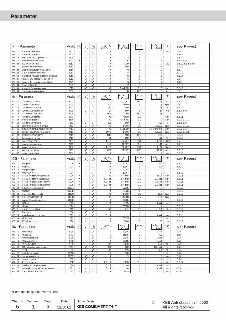
Parameter
5 1 KEB COMBIVERT F4-F6Name: BasisChapter Section Page Date © KEB Antriebstechnik, 2002
All Rights reserved31.10.02
Pn - Parameter Addr. min max default [?] see Page(s)Pn 0 automatic retry UP 2200 - - 0 1 1 0 –– 6.6.6Pn 1 automatic retry OP 2201 - - 0 1 1 0 –– 6.6.6Pn 3 electronic motor protection 2203 - - - 0 4 1 0 6.6.3Pn 7 speed search condition 2207 - 0 15 1 8 –– 6.6.5, 6.6.6Pn 16 E.dOH delay time 2210 - - 0 120 1 0 sec 6.3.10, 6.6.3, 6.6.4Pn 17 power off start voltage 2211 - 198 800 1 198 –– 6.8.13Pn 20 extern fault stopping condition 2214 - 0 6 1 0 –– 6.6.4Pn 23 E.bus stopping condition 2217 - 0 6 1 6 –– 11.2.3Pn 24 prohibited rotation stopping condition 2218 - 0 6 1 6 –– 6.11.7Pn 25 warning dOH stopping condition 2219 - 0 6 1 6 –– 6.6.3Pn 26 warning OH stopping condition 221A - 0 6 1 6 –– 6.6.3Pn 33 power off mode 2221 - 1 2 1 2 –– 6.8.13Pn 60 torque for abnormal stop 223C - 0,0 5 x dr.09 0,1 ? Nm 6.8.13Pn 63 emergency-stop-ramp 223F - - - 0 10 0,01 0 sec 6.6.7
dr - Parameter Addr. min max default [?] see Page(s)dr 0 rated motor power 2400 - 0 ,01 327,67 0,01 *) kW 6.5.3dr 1 rated motor speed 2401 - 100 9999 1 *) rpm 6.5.3dr 2 rated motor current 2402 - 0,1 1000 0,1 *) A 6.5.3dr 3 rated motor frequency 2403 - 20 500 1 50 Hz 6.5.3, 6.5.5dr 4 rated motor cos (phi) 2404 - 0,05 1,00 0,01 *) –– 6.5.3dr 9 rated motor torque 2409 - - - 0,1 500,0 0,1 –– Nm 6.5.11dr 10 maximum torque 240A - - - 0,1 Inv. max. 0,1 –– Nm 6.5.5, 6.5.11dr 12 rated motor voltage 240C - 100 500 1 400 V 6.5.3, 6.5.5dr 13 speed for maximum torque 240D - 0,0 14000 0,5 1000,0 rpm 6.5.5, 6.5.11dr 16 maximum torque corner speed 2410 - 0,0 5 x dr.09 0,1 1,5 x dr.09 *) Nm 6.5.5, 6.5.11dr 19 corner speed field weakening 2413 - 200,0 14000 0,5 1300,0 rpm 6.5.6, 6.5.12dr 20 field weakening curve 2414 - 0,10 2,00 0,01 1,20 –– 6.5.12dr 21 flux adaption factor 2415 - 25 250 1 100 % 6.5.12dr 48 rotor resistance 2430 - - 0,001 32,767 0,001 1,100 Ohm 6.5.7dr 49 magnetic inductance 2431 - - 10,0 3276,7 0,1 146 mH 6.5.7dr 50 stator resistance 2432 - 0,000 32,767 0,001 1,100 Ohm 6.5.13dr 51 leakage reactance 2433 - 0,00 327,67 0,01 10,58 mH 6.5.13dr 52 motor connection 2434 - 0 1 1 1 –– 6.5.13
CS - Parameter Addr. min max default [?] see Page(s)CS 0 KP speed 2D00 - 0 32767 1 400 –– 6.5.10CS 1 KI speed 2D01 - 0 32767 1 200 –– 6.5.10CS 3 KP speed gain 2D03 - - 0 32767 1 0 –– 6.5.10CS 4 KP speed limit 2D04 - - 0 32767 1 0 –– 6.5.10CS 6 torque limit forward positive 2D06 - 0,0 5 x dr.9 0,1 dr.10 Nm 6.5.11CS 7 torque limit reverse positive 2D07 - -0,1 : off 5 x dr.9 0,1 -0,1 : off Nm 6.5.11CS 8 torque limit forward negative 2D08 - -0,1 : off 5 x dr.9 0,1 -0,1 : off Nm 6.5.11CS 9 torque limit reverse negative 2D09 - -0,1 : off 5 x dr.9 0,1 -0,1 : off Nm 6.5.11CS 10 aktivation of adaptation 2D0A - - 0 65535 1 0 –– 6.5.13CS 11 KI offset 2D0B - - 0 65535 1 0 –– 6.5.10CS 12 max speed for max Ki 2D0C - - 0,0 14000 0,5 10,0 rpm 6.5.10CS 13 min. speed for Cs.01 2D0D - - 0,0 14000 0,5 500,0 rpm 6.5.10CS 14 standstill position control 2D0E - - 0 65535 1 0 –– 6.5.10CS 19 KP flux 2D13 - - 0 : off 65535 1 0 : off –– 6.5.12CS 20 KI flux 2D14 - - 1 65535 1 1 –– 6.5.12CS 21 magn. current limit 2D15 - - 0,0 In.1 0,1 0,0 A 6.5.12CS 22 flux mode 2D16 - 0 1 1 0 –– 6.5.13CS 23 speed regulation active 2D17 0 : off 1 1 0 : off –– 6.5.5CS 39 KP U-max 2D27 - - - 0 65535 1 0 –– 6.5.13CS 40 PT1-time U-max 2D28 - - - 0 5000 0 100 ms 6.5.13
ds - Parameter Addr. min max default [?] see Page(s)ds 0 KP I active 2F00 - - 1 65535 1 1500 –– 6.5.9ds 1 KI I active 2F01 - - 1 65535 1 500 –– 6.5.9ds 5 KP I magnetizing 2F05 - - 0 65535 1 -1 : off –– 6.5.9ds 6 KI I magnetizing 2F06 - - 0 65535 1 -1 : off –– 6.5.9ds 9 no load voltage 2F09 - - 0,0 100,0 0,1 75,0 % 6.5.9ds 10 DC voltage compensation 2F0A - 180 500 1 501 : off V 6.5.6ds 11 boost 2F0B - - 0,0 25,5 0,1 2,0 % 6.5.6ds 12 modulation depth 2F0C - - - 0 100 1 % 6.5.8ds 13 carrier frequency 2F0D - 0 1 1 0 –– 6.5.8ds 14 overmodulation 2F0E - 0 1 1 1 –– 6.5.8dS 15 Adaption factor 2F0F - - - 0,0 : off 100,0 0,1 - % 6.5.14ds 16 dead time compensation 2D10 - - - 0 : off 1 : on 1 0 : off ––ds 17 waiting for magnetisation current 2D11 - - - 0 : off 1 : on 1 0 : off –– 6.5.8ds 18 equv circuit identification 2D12 - - - 0 9999 1 0 –– 6.5.6
*) dependent by the inverter size
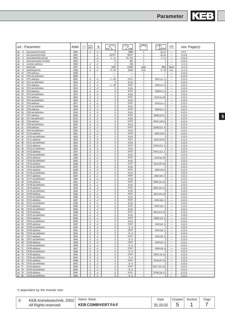
7
5
Parameter
5 1 7KEB COMBIVERT F4-F
Name: Basis Section PageDate© KEB Antriebstechnik, 2002All Rights reserved
Chapter
31.10.02
ud - Parameter Addr. min max default [?] see Page(s)ud 0 key password input 2600 - 0 9999 1 cp_on –– 4.4.3ud 1 bus password input 2601 - - -32767 32767 1 cp_on –– 6.12.5ud 2 start parameter group 2602 - - 1 : ru 16 : Pd 1 1 : ru –– 6.12.4ud 3 start parameter number 2603 - - 0 255 1 1 –– 6.12.4ud 6 inverter address 2606 - 0 239 1 1 –– 11.2.3ud 7 baud rate 2607 - 1200 57600 table 9600 Baud 11.2.3ud 8 watchdog time 2608 - 0 : off 10,00 0,01 0 : off sec 11.2.3ud 13 CP0 address 260D - - - –– –– 1 –– –– 6.12.5ud 14 CP0 set definition 260E - - - –– –– 1 –– –– 6.12.5ud 15 CP1 address 260F - -1 : off 7FFF 1 2001 (ru. 1) –– 6.12.4ud 16 CP1 set definition 2610 - 0 8 (A) 1 0 –– 6.12.4ud 17 CP2 address 2611 - -1 : off 7FFF 1 2000 (ru. 0) –– 6.12.4ud 18 CP2 set definition 2612 - 0 8 (A) 1 0 –– 6.12.4ud 19 CP3 address 2613 - 0 7FFF 1 2009 (ru. 9) –– 6.12.4ud 20 CP3 set definition 2614 - 0 8 (A) 1 0 –– 6.12.4ud 21 CP4 address 2615 - 0 7FFF 1 2019 (ru.25) –– 6.12.4ud 22 CP4 set definition 2616 - 0 8 (A) 1 0 –– 6.12.4ud 23 CP5 address 2617 - 0 7FFF 1 2002 (ru. 2) –– 6.12.4ud 24 CP5 set definition 2618 - 0 8 (A) 1 0 –– 6.12.4ud 25 CP6 address 2619 - 0 7FFF 1 2004 (ru. 4) –– 6.12.4ud 26 CP6 set definition 261A - 0 8 (A) 1 0 –– 6.12.4ud 27 CP7 address 261B - 0 7FFF 1 300B (sP.11) –– 6.12.4ud 28 CP7 set definition 261C - 0 8 (A) 1 0 –– 6.12.4ud 29 CP8 address 261D - 0 7FFF 1 300C (sP.12) –– 6.12.4ud 30 CP8 set definition 261E - 0 8 (A) 1 0 –– 6.12.4ud 31 CP9 address 261F - 0 7FFF 1 2D06 (Cs. 6) –– 6.12.4ud 32 CP9 set definition 2620 - 0 8 (A) 1 0 –– 6.12.4ud 33 CP10 address 2621 - 0 7FFF 1 3005 (sP. 5) –– 6.12.4ud 34 CP10 set definition 2622 - 0 8 (A) 1 0 –– 6.12.4ud 35 CP11 address 2623 - 0 7FFF 1 3016 (sP.22) –– 6.12.4ud 36 CP11 set definition 2624 - 0 8 (A) 1 0 –– 6.12.4ud 37 CP12 address 2625 - 0 7FFF 1 2D00 (Cs. 0) –– 6.12.4ud 38 CP12 set definition 2626 - 0 8 (A) 1 0 –– 6.12.4ud 39 CP13 address 2627 - 0 7FFF 1 2D01 (Cs. 1) –– 6.12.4ud 40 CP13 set definition 2628 - 0 8 (A) 1 0 –– 6.12.4ud 41 CP14 address 2629 - 0 7FFF 1 2419 (dr.25) –– 6.12.4ud 42 CP14 set definition 262A - 0 8 (A) 1 0 –– 6.12.4ud 43 CP15 address 262B - 0 7FFF 1 2214 (Pn.20) –– 6.12.4ud 44 CP15 set definition 262C - 0 8 (A) 1 0 –– 6.12.4ud 45 CP16 address 262D - 0 7FFF 1 2804 (An.4) –– 6.12.4ud 46 CP16 set definition 262E - 0 8 (A) 1 0 –– 6.12.4ud 47 CP17 address 262F - 0 7FFF 1 2802 (An. 2) –– 6.12.4ud 48 CP17 set definition 2630 - 0 8 (A) 1 0 –– 6.12.4ud 49 CP18 address 2631 - 0 7FFF 1 280E (An.14) –– 6.12.4ud 50 CP18 set definition 2632 - 0 8 (A) 1 0 –– 6.12.4ud 51 CP19 address 2633 - 0 7FFF 1 280F (An.15) –– 6.12.4ud 52 CP19 set definition 2634 - 0 8 (A) 1 0 –– 6.12.4ud 53 CP20 address 2635 - 0 7FFF 1 2813 (An.19) –– 6.12.4ud 54 CP20 set definition 2636 - 0 8 (A) 1 0 –– 6.12.4ud 55 CP21 address 2637 - 0 7FFF 1 2A01 (do. 1) –– 6.12.4ud 56 CP21 set definition 2638 - 0 8 (A) 1 0 –– 6.12.4ud 57 CP22 address 2639 - 0 7FFF 1 2A02 (do. 2) –– 6.12.4ud 58 CP22 set definition 263A - 0 8 (A) 1 0 –– 6.12.4ud 59 CP23 address 263B - 0 7FFF 1 2B14 (LE.20) –– 6.12.4ud 60 CP23 set definition 263C - 0 8 (A) 1 0 –– 6.12.4ud 61 CP24 address 263D - 0 7FFF 1 2B05 (LE. 5) –– 6.12.4ud 62 CP24 set definition 263E - 0 8 (A) 1 0 –– 6.12.4ud 63 CP25 address 263F - 0 7FFF 1 2400 (dr. 0) –– 6.12.4ud 64 CP25 set definition 2640 - 0 8 : A 1 0 –– 6.12.4ud 65 CP26 address 2641 - 0 7FFF 1 2401 (dr. 1) –– 6.12.4ud 66 CP26 set definition 2642 - 0 8 : A 1 0 –– 6.12.4ud 67 CP27 address 2643 - 0 7FFF 1 2402 (dr. 2) –– 6.12.4ud 68 CP27 set definition 2644 - 0 8 : A 1 0 –– 6.12.4ud 69 CP28 address 2645 - 0 7FFF 1 2403 (dr. 3) –– 6.12.4ud 70 CP28 set definition 2646 - 0 8 : A 1 0 –– 6.12.4ud 71 CP29 address 2647 - 0 7FFF 1 2404 (dr. 4) –– 6.12.4ud 72 CP29 set definition 2648 - 0 8 : A 1 0 –– 6.12.4ud 73 CP30 address 2649 - 0 7FFF 1 240C (dr.12) –– 6.12.4ud 74 CP30 set definition 264A - 0 8 : A 1 0 –– 6.12.4ud 75 CP31 address 264B - 0 7FFF 1 270A (Fr.10) –– 6.12.4ud 76 CP31 set definition 264C - 0 8 : A 1 0 –– 6.12.4ud 77 CP32 address 264D - 0 7FFF 1 2D17 (Cs.23) –– 6.12.4ud 78 CP32 set definition 264E - 0 8 : A 1 0 –– 6.12.4ud 79 CP33 address 264F - 0 7FFF 1 2F0B (ds.11) –– 6.12.4ud 80 CP33 set definition 2650 - 0 8 : A 1 0 –– 6.12.4
*) dependent by the inverter size
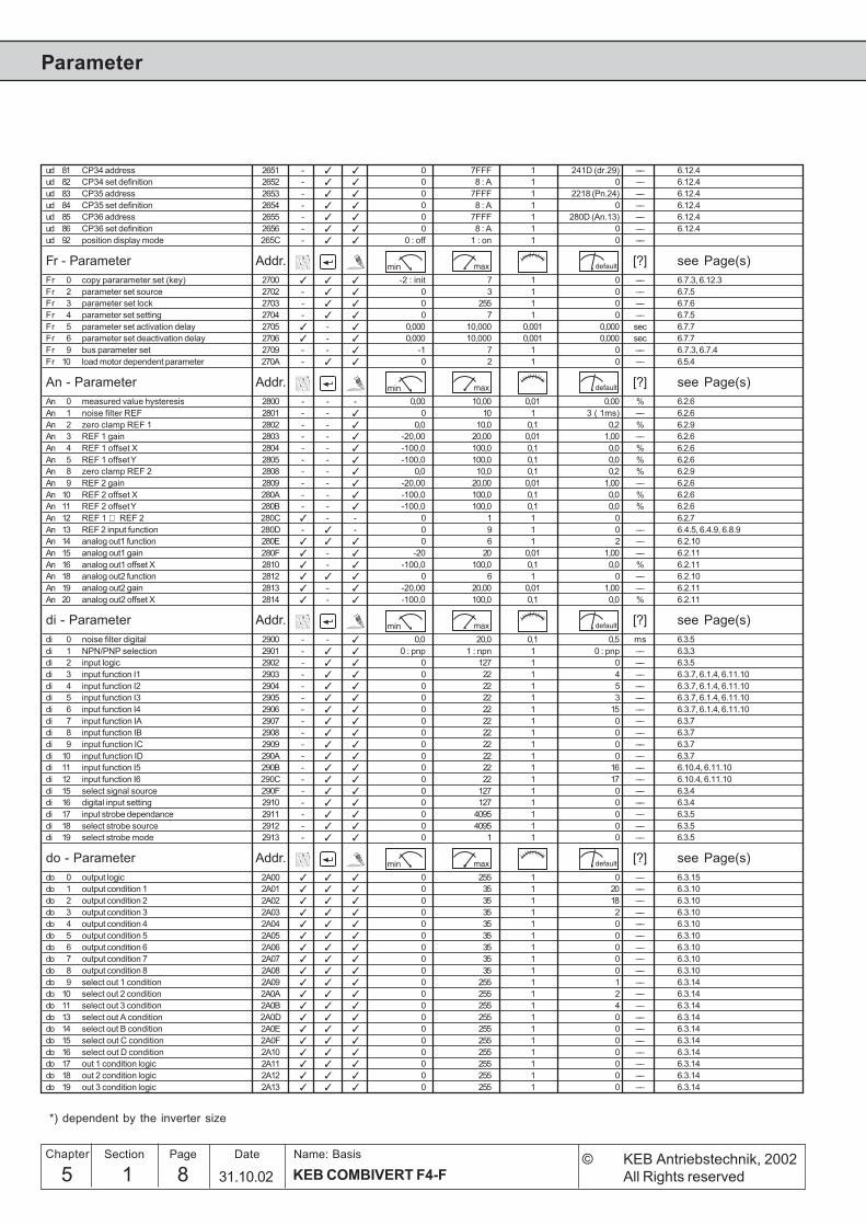
Parameter
5 1 KEB COMBIVERT F4-F8Name: BasisChapter Section Page Date © KEB Antriebstechnik, 2002
All Rights reserved31.10.02
ud 81 CP34 address 2651 - 0 7FFF 1 241D (dr.29) –– 6.12.4
ud 82 CP34 set definition 2652 - 0 8 : A 1 0 –– 6.12.4
ud 83 CP35 address 2653 - 0 7FFF 1 2218 (Pn.24) –– 6.12.4
ud 84 CP35 set definition 2654 - 0 8 : A 1 0 –– 6.12.4
ud 85 CP36 address 2655 - 0 7FFF 1 280D (An.13) –– 6.12.4
ud 86 CP36 set definition 2656 - 0 8 : A 1 0 –– 6.12.4
ud 92 position display mode 265C - 0 : off 1 : on 1 0 ––
Fr - Parameter Addr. min max default [?] see Page(s)
Fr 0 copy pararameter set (key) 2700 -2 : init 7 1 0 –– 6.7.3, 6.12.3
Fr 2 parameter set source 2702 - 0 3 1 0 –– 6.7.5
Fr 3 parameter set lock 2703 - 0 255 1 0 –– 6.7.6
Fr 4 parameter set setting 2704 - 0 7 1 0 –– 6.7.5
Fr 5 parameter set activation delay 2705 - 0,000 10,000 0,001 0,000 sec 6.7.7
Fr 6 parameter set deactivation delay 2706 - 0,000 10,000 0,001 0,000 sec 6.7.7
Fr 9 bus parameter set 2709 - - -1 7 1 0 –– 6.7.3, 6.7.4
Fr 10 load motor dependent parameter 270A - 0 2 1 0 –– 6.5.4
An - Parameter Addr. min max default [?] see Page(s)
An 0 measured value hysteresis 2800 - - - 0,00 10,00 0,01 0,00 % 6.2.6
An 1 noise filter REF 2801 - - 0 10 1 3 ( 1ms) –– 6.2.6
An 2 zero clamp REF 1 2802 - - 0,0 10,0 0,1 0,2 % 6.2.9
An 3 REF 1 gain 2803 - - -20,00 20,00 0,01 1,00 –– 6.2.6
An 4 REF 1 offset X 2804 - - -100,0 100,0 0,1 0,0 % 6.2.6
An 5 REF 1 offset Y 2805 - - -100,0 100,0 0,1 0,0 % 6.2.6
An 8 zero clamp REF 2 2808 - - 0,0 10,0 0,1 0,2 % 6.2.9
An 9 REF 2 gain 2809 - - -20,00 20,00 0,01 1,00 –– 6.2.6
An 10 REF 2 offset X 280A - - -100,0 100,0 0,1 0,0 % 6.2.6
An 11 REF 2 offset Y 280B - - -100,0 100,0 0,1 0,0 % 6.2.6
An 12 REF 1 ⇔ REF 2 280C - - 0 1 1 0 6.2.7
An 13 REF 2 input function 280D - - 0 9 1 0 –– 6.4.5, 6.4.9, 6.8.9
An 14 analog out1 function 280E 0 6 1 2 –– 6.2.10
An 15 analog out1 gain 280F - -20 20 0,01 1,00 –– 6.2.11
An 16 analog out1 offset X 2810 - -100,0 100,0 0,1 0,0 % 6.2.11
An 18 analog out2 function 2812 0 6 1 0 –– 6.2.10
An 19 analog out2 gain 2813 - -20,00 20,00 0,01 1,00 –– 6.2.11
An 20 analog out2 offset X 2814 - -100,0 100,0 0,1 0,0 % 6.2.11
di - Parameter Addr. min max default [?] see Page(s)
di 0 noise filter digital 2900 - - 0,0 20,0 0,1 0,5 ms 6.3.5
di 1 NPN/PNP selection 2901 - 0 : pnp 1 : npn 1 0 : pnp –– 6.3.3
di 2 input logic 2902 - 0 127 1 0 –– 6.3.5
di 3 input function I1 2903 - 0 22 1 4 –– 6.3.7, 6.1.4, 6.11.10
di 4 input function I2 2904 - 0 22 1 5 –– 6.3.7, 6.1.4, 6.11.10
di 5 input function I3 2905 - 0 22 1 3 –– 6.3.7, 6.1.4, 6.11.10
di 6 input function I4 2906 - 0 22 1 15 –– 6.3.7, 6.1.4, 6.11.10
di 7 input function IA 2907 - 0 22 1 0 –– 6.3.7
di 8 input function IB 2908 - 0 22 1 0 –– 6.3.7
di 9 input function IC 2909 - 0 22 1 0 –– 6.3.7
di 10 input function ID 290A - 0 22 1 0 –– 6.3.7
di 11 input function I5 290B - 0 22 1 16 –– 6.10.4, 6.11.10
di 12 input function I6 290C - 0 22 1 17 –– 6.10.4, 6.11.10
di 15 select signal source 290F - 0 127 1 0 –– 6.3.4
di 16 digital input setting 2910 - 0 127 1 0 –– 6.3.4
di 17 input strobe dependance 2911 - 0 4095 1 0 –– 6.3.5
di 18 select strobe source 2912 - 0 4095 1 0 –– 6.3.5
di 19 select strobe mode 2913 - 0 1 1 0 –– 6.3.5
do - Parameter Addr. min max default [?] see Page(s)
do 0 output logic 2A00 0 255 1 0 –– 6.3.15
do 1 output condition 1 2A01 0 35 1 20 –– 6.3.10
do 2 output condition 2 2A02 0 35 1 18 –– 6.3.10
do 3 output condition 3 2A03 0 35 1 2 –– 6.3.10
do 4 output condition 4 2A04 0 35 1 0 –– 6.3.10
do 5 output condition 5 2A05 0 35 1 0 –– 6.3.10
do 6 output condition 6 2A06 0 35 1 0 –– 6.3.10
do 7 output condition 7 2A07 0 35 1 0 –– 6.3.10
do 8 output condition 8 2A08 0 35 1 0 –– 6.3.10
do 9 select out 1 condition 2A09 0 255 1 1 –– 6.3.14
do 10 select out 2 condition 2A0A 0 255 1 2 –– 6.3.14
do 11 select out 3 condition 2A0B 0 255 1 4 –– 6.3.14
do 13 select out A condition 2A0D 0 255 1 0 –– 6.3.14
do 14 select out B condition 2A0E 0 255 1 0 –– 6.3.14
do 15 select out C condition 2A0F 0 255 1 0 –– 6.3.14
do 16 select out D condition 2A10 0 255 1 0 –– 6.3.14
do 17 out 1 condition logic 2A11 0 255 1 0 –– 6.3.14
do 18 out 2 condition logic 2A12 0 255 1 0 –– 6.3.14
do 19 out 3 condition logic 2A13 0 255 1 0 –– 6.3.14
*) dependent by the inverter size
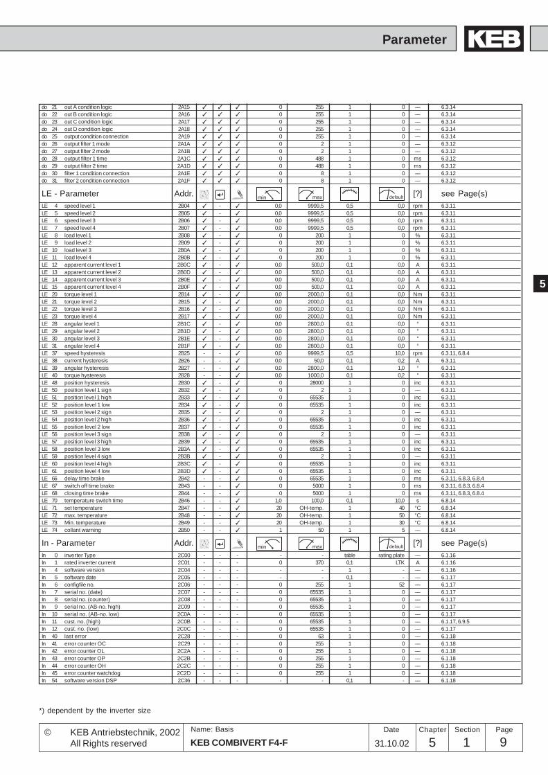
9
5
Parameter
5 1 9KEB COMBIVERT F4-F
Name: Basis Section PageDate© KEB Antriebstechnik, 2002All Rights reserved
Chapter
31.10.02
do 21 out A condition logic 2A15 0 255 1 0 –– 6.3.14do 22 out B condition logic 2A16 0 255 1 0 –– 6.3.14do 23 out C condition logic 2A17 0 255 1 0 –– 6.3.14do 24 out D condition logic 2A18 0 255 1 0 –– 6.3.14do 25 output condition connection 2A19 0 255 1 0 –– 6.3.14do 26 output filter 1 mode 2A1A 0 2 1 0 –– 6.3.12do 27 output filter 2 mode 2A1B 0 2 1 0 –– 6.3.12do 28 output filter 1 time 2A1C 0 488 1 0 ms 6.3.12do 29 output filter 2 time 2A1D 0 488 1 0 ms 6.3.12do 30 filter 1 condition connection 2A1E 0 8 1 0 –– 6.3.12do 31 filter 2 condition connection 2A1F 0 8 1 0 –– 6.3.12
LE - Parameter Addr. min max default [?] see Page(s)LE 4 speed level 1 2B04 - 0,0 9999,5 0,5 0,0 rpm 6.3.11LE 5 speed level 2 2B05 - 0,0 9999,5 0,5 0,0 rpm 6.3.11LE 6 speed level 3 2B06 - 0,0 9999,5 0,5 0,0 rpm 6.3.11LE 7 speed level 4 2B07 - 0,0 9999,5 0,5 0,0 rpm 6.3.11LE 8 load level 1 2B08 - 0 200 1 0 % 6.3.11LE 9 load level 2 2B09 - 0 200 1 0 % 6.3.11LE 10 load level 3 2B0A - 0 200 1 0 % 6.3.11LE 11 load level 4 2B0B - 0 200 1 0 % 6.3.11LE 12 apparent current level 1 2B0C - 0,0 500,0 0,1 0,0 A 6.3.11LE 13 apparent current level 2 2B0D - 0,0 500,0 0,1 0,0 A 6.3.11LE 14 apparent current level 3 2B0E - 0,0 500,0 0,1 0,0 A 6.3.11LE 15 apparent current level 4 2B0F - 0,0 500,0 0,1 0,0 A 6.3.11LE 20 torque level 1 2B14 - 0,0 2000,0 0,1 0,0 Nm 6.3.11LE 21 torque level 2 2B15 - 0,0 2000,0 0,1 0,0 Nm 6.3.11LE 22 torque level 3 2B16 - 0,0 2000,0 0,1 0,0 Nm 6.3.11LE 23 torque level 4 2B17 - 0,0 2000,0 0,1 0,0 Nm 6.3.11LE 28 angular level 1 2B1C - 0,0 2800,0 0,1 0,0 ° 6.3.11LE 29 angular level 2 2B1D - 0,0 2800,0 0,1 0,0 ° 6.3.11LE 30 angular level 3 2B1E - 0,0 2800,0 0,1 0,0 ° 6.3.11LE 31 angular level 4 2B1F - 0,0 2800,0 0,1 0,0 ° 6.3.11LE 37 speed hysteresis 2B25 - - 0,0 9999,5 0,5 10,0 rpm 6.3.11, 6.8.4LE 38 current hysteresis 2B26 - - 0,0 50,0 0,1 0,2 A 6.3.11LE 39 angular hysteresis 2B27 - - 0,0 2800,0 0,1 1,0 ° 6.3.11LE 40 torque hysteresis 2B28 - - 0,0 1000,0 0,1 0,2 ° 6.3.11LE 48 position hysteresis 2B30 - 0 28000 1 0 inc 6.3.11LE 50 position level 1 sign 2B32 - 0 2 1 0 –– 6.3.11LE 51 position level 1 high 2B33 - 0 65535 1 0 inc 6.3.11LE 52 position level 1 low 2B34 - 0 65535 1 0 inc 6.3.11LE 53 position level 2 sign 2B35 - 0 2 1 0 –– 6.3.11LE 54 position level 2 high 2B36 - 0 65535 1 0 inc 6.3.11LE 55 position level 2 low 2B37 - 0 65535 1 0 inc 6.3.11LE 56 position level 3 sign 2B38 - 0 2 1 0 — 6.3.11LE 57 position level 3 high 2B39 - 0 65535 1 0 inc 6.3.11LE 58 position level 3 low 2B3A - 0 65535 1 0 inc 6.3.11LE 59 position level 4 sign 2B3B - 0 2 1 0 –– 6.3.11LE 60 position level 4 high 2B3C - 0 65535 1 0 inc 6.3.11LE 61 position level 4 low 2B3D - 0 65535 1 0 inc 6.3.11LE 66 delay time brake 2B42 - - 0 65535 1 0 ms 6.3.11, 6.8.3, 6.8.4LE 67 switch off time brake 2B43 - - 0 5000 1 0 ms 6.3.11, 6.8.3, 6.8.4LE 68 closing time brake 2B44 - - 0 5000 1 0 ms 6.3.11, 6.8.3, 6.8.4LE 70 temperature switch time 2B46 - - 1,0 100,0 0,1 10,0 s 6.8.14LE 71 set temperature 2B47 - - 20 OH-temp. 1 40 °C 6.8.14LE 72 max. temperature 2B48 - - 20 OH-temp. 1 50 °C 6.8.14LE 73 Min. temperature 2B49 - - 20 OH-temp. 1 30 °C 6.8.14LE 74 collant warning 2B50 - - 1 50 1 5 –– 6.8.14
In - Parameter Addr. min max default [?] see Page(s)In 0 inverter Type 2C00 - - - - - table rating plate –– 6.1.16In 1 rated inverter current 2C01 - - - 0 370 0,1 LTK A 6.1.16In 4 software version 2C04 - - - - - 1 - –– 6.1.16In 5 software date 2C05 - - - - - 0,1 - –– 6.1.17In 6 configfile no. 2C06 - - - 0 255 1 52 –– 6.1.17In 7 serial no. (date) 2C07 - - - 0 65535 1 0 –– 6.1.17In 8 serial no. (counter) 2C08 - - - 0 65535 1 0 –– 6.1.17In 9 serial no. (AB-no. high) 2C09 - - - 0 65535 1 0 –– 6.1.17In 10 serial no. (AB-no. low) 2C0A - - - 0 65535 1 0 –– 6.1.17In 11 cust. no. (high) 2C0B - - - 0 65535 1 0 –– 6.1.17, 6.9.5In 12 cust. no. (low) 2C0C - - - 0 65535 1 0 –– 6.1.17In 40 last error 2C28 - - - 0 63 1 0 –– 6.1.18In 41 error counter OC 2C29 - - - 0 255 1 0 –– 6.1.18In 42 error counter OL 2C2A - - - 0 255 1 0 –– 6.1.18In 43 error counter OP 2C2B - - - 0 255 1 0 –– 6.1.18In 44 error counter OH 2C2C - - - 0 255 1 0 –– 6.1.18In 45 error counter watchdog 2C2D - - - 0 255 1 0 –– 6.1.18In 54 software version DSP 2C36 - - - - - 0,1 - –– 6.1.18
*) dependent by the inverter size
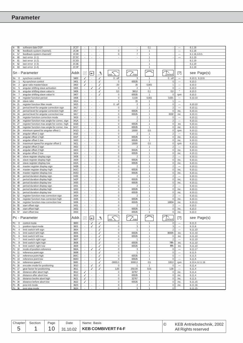
Parameter
5 1 KEB COMBIVERT F4-F10Name: BasisChapter Section Page Date © KEB Antriebstechnik, 2002
All Rights reserved31.10.02
In 55 software date DSP 2C37 - - - - - 0,1 - –– 6.1.18In 56 feedback-system channel1 2C38 - - - 0 7 1 - –– 6.1.18In 57 feedback-system channel2 2C39 - - - 0 7 1 - –– 6.1.18, 6.9.5In 60 last error (t-1) 2C3C - - - - - 1 - –– 6.1.19In 61 last error (t-2) 2C3D 1 6.1.19In 62 last error (t-3) 2C3E 1 6.1.19In 63 last error (t-4) 2C3F 1 6.1.19
Sn - Parameter Addr. min max default [?] see Page(s)Sn 0 synchron control 3400 - 0 : off 3 1 0 : off –– 6.10.3, 6.10.6Sn 1 Kp synchron control 3401 - 0 65535 1 0 –– 6.10.3Sn 2 gear ratio master/slave 3402 - -20 20 0,001 1 –– 6.10.3Sn 5 angular shifting slave activation 3405 - 0 2 1 0 –– 6.10.3Sn 6 angular shifting slave value lo 3406 - - 0,0 360,0 0,1 0,0 ° 6.10.3Sn 7 angular shifting slave value hi 3407 - - 0 65535 1 0 rpm 6.10.3Sn 8 register function period 3408 - - - 0 0,100 0,001 0,001 –– 6.10.10Sn 19 slave ratio 3414 - - - 1 15 1 1 ––Sn 21 register function filter mode 3415 - - - 0 : off 2 1 0 –– 6.10.10Sn 22 period level for angular correction sign 3417 - - - 0 2 1 2 –– 6.10.11Sn 23 period level for angular correction high 3417 - - - 0 65535 1 0 inc. 6.10.11Sn 24 period level for angular correction low 3417 - - - 0 65535 1 8192 inc. 6.10.11Sn 25 register function correction mode 3419 - - - 0 2 1 0 –– 6.10.11Sn 26 register function max angle for correc. sign 341A - - - 0 2 1 2 –– 6.10.11Sn 27 register function max angle for correc. high 341B - - - 0 65535 1 0 inc 6.10.11Sn 28 register function max angle for correc. low 341C - - - 0 65535 1 0 inc. 6.10.11Sn 29 minimum speed for angular offest 1 341D - - - 0 15000 0,5 0 rpm 6.10.11Sn 30 angular offset 1 sign 341E - - - 0 2 1 2 –– 6.10.11Sn 31 angular offset 1 high 341F - - - 0 65535 1 0 inc. 6.10.11Sn 32 angular offset 1 low 3420 - - - 0 65535 1 0 inc. 6.10.11Sn 33 maximum speed for angular offset 2 3421 - - - 0 15000 0,5 0 rpm 6.10.11Sn 34 angular offset 2 sign 3422 - - - 0 2 1 2 –– 6.10.11Sn 35 angular offset 2 high 3423 - - - 0 65535 1 0 inc. 6.10.11Sn 36 angular offset 2 low 3424 - - - 0 65535 1 0 inc. 6.10.11Sn 40 slave register display sign 3428 - - - 0 2 1 2 –– 6.10.11Sn 41 slave register display high 3429 - - - 0 65535 1 0 inc. 6.10.11Sn 42 slave register display low 342A - - - 0 65535 1 0 inc. 6.10.11Sn 43 master register display sign 342B - - - 0 2 1 2 –– 6.10.11Sn 44 master register display high 342C - - - 0 65535 1 0 inc. 6.10.11Sn 45 master register display low 342D - - - 0 65535 1 0 inc. 6.10.11Sn 46 period duration display sign 342E - - - 0 2 1 2 –– 6.10.11Sn 47 period duration display high 342F - - - 0 65535 1 0 inc. 6.10.11Sn 48 period duration display low 3430 - - - 0 65535 1 0 inc. 6.10.11Sn 49 period duration display sign 3431 - - - 0 2 1 2 –– 6.10.11Sn 50 period duration display high 3432 - - - 0 65535 1 0 inc. 6.10.11Sn 51 period duration display low 3433 - - - 0 65535 1 0 inc. 6.10.11Sn 52 register function max correction sign 3434 - - - 0 2 1 2 –– 6.10.11Sn 53 register function max correction high 3435 - - - 0 65535 1 0 inc. 6.10.11Sn 54 register function max correction low 3436 - - - 0 65535 1 16834 inc. 6.10.11Sn 55 start offset sign 3431 - - - 0 2 1 2 –– 6.10.3Sn 56 start offset high 3432 - - - 0 65535 1 0 inc. 6.10.3Sn 57 start offset low 3433 - - - 0 65535 1 0 inc. 6.10.3
Pc - Parameter Addr. min max default [?] see Page(s)Pc 0 control mode 3600 - 0 1 1 0 –– 6.11.3Pc 1 position input mode 3601 - 0 3 1 3 –– 6.11.6Pc 4 limit switch left sign 3604 - - 0 1 1 2 –– 6.11.10Pc 5 limit switch left high 3605 - - 0 65535 1 8000h inc 6.11.10Pc 6 limit switch left low 3606 - - 0 65535 1 0 inc 6.11.10Pc 7 limit switch right sign 3607 - - 0 1 1 2 –– 6.11.10Pc 8 limit switch right high 3608 - - 0 65535 1 7fffh inc 6.11.10Pc 9 limit switch right low 3609 - - 0 65535 1 ffffh inc 6.11.10Pc 10 mode of position reference 360A - 0 3 1 0 –– 6.11.17Pc 11 reference point sign 360B - - 0 1 1 0 –– 6.11.5Pc 12 reference point high 360C - - 0 65535 1 0 –– 6.11.5Pc 13 reference point low 360D - - 0 65535 1 0 –– 6.11.5Pc 14 reference speed 1 360E - - -3000,0 3000,0 0,5 100,0 rpm 6.10.4, 6.11.16Pc 16 encoder mode for positioning 3610 - 0 1 1 0 –– 6.11.4Pc 17 gear factor for positioning 3611 - 1,00 250,00 0,01 1,00 –– 6.11.4Pc 18 distance after abort high 3612 - - 0 32767 1 0 inc. 6.11.4Pc 19 distance after abort low 3613 - - 0 65535 1 0 inc. 6.11.4Pc 33 distance beofre abort high 3621 - - 0 32767 1 0 inc. 6.11.5Pc 34 distance before abort low 3622 - - 0 65535 1 0 inc. 6.11.15Pc 35 posi init mode 3623 - - - 0 2 1 0 inc. 6.11.16Pc 36 posi stop mode 3624 - - - 0 3 1 0 6.11.15
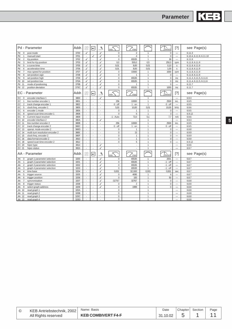
11
5
Parameter
5 1 11KEB COMBIVERT F4-F
Name: Basis Section PageDate© KEB Antriebstechnik, 2002All Rights reserved
Chapter
31.10.02
Pd - Parameter Addr. min max default [?] see Page(s)Pd 0 posi mode 3700 - 0 2 1 0 –– 6.11.3Pd 1 manuell start 3701 - 0 4 1 0 –– 6.10.4, 6.11.9, 6.11.10Pd 2 Kp position 3702 - 0 65535 1 30 –– 6.11.9Pd 3 limit for Kp position 3703 - 0,0 500,0 0,5 250,0 rpm 6.11.8, 6.11.9Pd 5 s curve time 3705 - 0,01 8,00 0,01 0,10 s 6.11.8, 6.11.9Pd 6 acceleration time 3706 - 0,01 8,00 0,01 1,00 s 6.11.8, 6.11.9Pd 7 max speed for position 3707 - 0 10000 1 1000 rpm 6.11.8, 6.11.9Pd 8 set position sign 3708 - 0 1 1 0 –– 6.11.8, 6.11.9Pd 9 set position high 3709 - 0 65535 1 0 inc 6.11.4, 6.11.5, 6.11.6Pd 10 set position low 370A - 0 65535 1 0 inc 6.11.4, 6.11.5, 6.11.6Pd 11 mode of positioning 370B - 0 1 1 0 –– 6.11.7Pd 12 position deviation 370C - 0 65535 1 1000 inc 6.11.7
EC - Parameter Addr. min max default [?] see Page(s)EC 0 encoder interface 1 3800 - - - - 1 - –– 6.9.3EC 1 line number encoder 1 3801 - - - 256 10000 1 2500 inc. 6.9.5EC 2 track change encoder 1 3802 - - - 0 : off 1 : on 1 0 : off –– 6.9.5EC 5 clock freq. encoder 1 3805 - - - 5,00 10,00 0,01 10,00 kHz 6.9.6EC 6 encoder 1 mode 3806 - - - 0 1 1 0 –– 6.9.5EC 8 speed scan time encoder 1 3808 - - - 0 5 1 3 –– 6.9.12EC 9 Current input resolver 3809 - - - -1 : Auto 72,0 0,1 7,7 mA 6.9.6EC 10 encoder interface 2 380A - - - - 1 - –– 6.9.3EC 11 line number encoder 2 380B - - - 256 10000 1 2500 inc. 6.9.5EC 12 track change encoder 2 380C - - - 0 : off 1 : on 1 0 : off –– 6.9.5EC 13 operat. mode encoder 2 380D - - - 0 1 1 0 –– 6.9.8EC 14 multi-turn resolution encoder 2 380E - - - 0 13 1 0 –– 6.9.9EC 15 clock freq. encoder 2 380F - - - 0 1 1 0 –– 6.9.9EC 16 data format encoder 2 3810 - - - 0 1 1 0 –– 6.9.9EC 18 speed scan time encoder 2 3812 - - - 0 5 1 0 –– 6.9.12EC 20 hiper-type 3814 - - - - 1 - –– 6.9.6EC 21 hiper-status 3815 - - - - 1 - –– 6.9.7
AA - Parameter Addr. min max default [?] see Page(s)AA 0 graph 1 parameter selection 3200 - - 0 65535 1 2001 –– 6.8.7AA 1 graph 2 parameter selection 3201 - - 0 65535 1 -1 : off –– 6.8.7AA 2 graph 3 parameter selection 3202 - - 0 65535 1 -1 : off –– 6.8.7AA 3 graph 4 parameter selection 3203 - - 0 65535 1 -1 : off –– 6.8.7AA 4 time base 3204 - - 0,001 32,000 0,001 0,001 sec 6.8.7AA 5 trigger source 3205 - - 0 4095 1 6 –– 6.8.7AA 6 trigger position 3206 - - 0 100 1 50 –– 6.8.7AA 7 syncronisation 3207 - - -32767 32767 1 0 –– 6.8.8AA 8 trigger status 3208 - - 0 2 1 0 –– 6.8.8AA 9 select graph address 3209 - - 0 1999 1 0 –– 6.8.8AA 10 read graph 1 320A - - - 0 1 –– 6.8.8AA 11 read graph 2 320B - - - 0 1 –– 6.8.8AA 12 read graph 3 320C - - - 0 1 –– 6.8.8AA 13 read graph 4 320D - - - 0 1 –– 6.8.8

Parameter
5 1 KEB COMBIVERT F4-F12Name: BasisChapter Section Page Date © KEB Antriebstechnik, 2002
All Rights reserved31.10.02
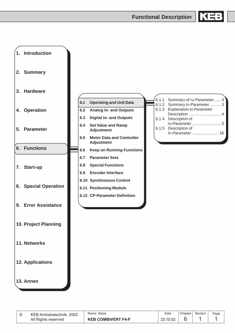
6 1 123.10.02Name: Basis
KEB COMBIVERT F4-FChapter Section PageDate© KEB Antriebstechnik, 2002
All Rights reserved
Functional Description
1. Introduction
2. Summary
3. Hardware
4. Operation
5. Parameter
6. Functions
7. Start-up
8. Special Operation
9. Error Assistance
10. Project Planning
11. Networks
12. Applications
13. Annex
6.1 Operating and Unit Data
6.2 Analog In- and Outputs
6.3 Digital In- and Outputs
6.4 Set Value and RampAdjustment
6.5 Motor Data and ControllerAdjustment
6.6 Keep on Running Functions
6.7 Parameter Sets
6.8 Special Functions
6.9 Encoder Interface
6.10 Synchronous Control
6.11 Positioning Module
6.12 CP-Parameter Definition
6.1.1 Summary of ru-Parameter ...... 36.1.2 Summary In-Parameter .......... 36.1.3 Explanation to Parameter
Description ............................. 46.1.4 Description of
ru-Parameter .......................... 56.1.5 Description of
In-Parameter ........................ 16

6 1Name: Basis
KEB COMBIVERT F4-F2 23.10.02
Fucntional Description
© KEB Antriebstechnik, 2002All Rights reserved
Chapter Section Page Date
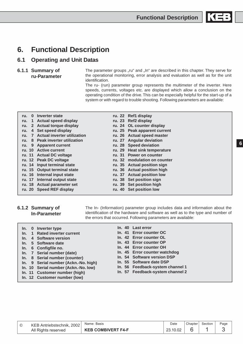
36 1 323.10.02KEB COMBIVERT F4-FName: Basis
6
Functional Description
© KEB Antriebstechnik, 2002All Rights reserved
Chapter Section PageDate
The parameter groups „ru“ and „In“ are described in this chapter. They serve forthe operational monitoring, error analysis and evaluation as well as for the unitidentification.The ru- (run) parameter group represents the multimeter of the inverter. Herespeeds, currents, voltages etc. are displayed which allow a conclusion on theoperating condition of the drive. This can be especially helpful for the start-up of asystem or with regard to trouble shooting. Following parameters are available:
The In- (Information) parameter group includes data and information about theidentification of the hardware and software as well as to the type and number ofthe errors that occurred. Following parameters are available:
6.1.1 Summary ofru-Parameter
6.1 Operating and Unit Datas
6.1.2 Summary ofIn-Parameter
ru. 0 Inverter stateru. 1 Actual speed displayru. 2 Actual torque displayru. 4 Set speed displayru. 7 Actual inverter utilizationru. 8 Peak inverter utilizationru. 9 Apparent currentru. 10 Active currentru. 11 Actual DC voltageru. 12 Peak DC voltageru. 14 Input terminal stateru. 15 Output terminal stateru. 16 Internal input stateru. 17 Internal output stateru. 18 Actual parameter setru. 20 Speed REF display
ru. 22 Ref1 displayru. 23 Ref2 displayru. 24 OL counter displayru. 25 Peak apparent currentru. 26 Actual speed masterru. 27 Angular deviationru. 28 Speed deviationru. 29 Heat sink temperatureru. 31 Power on counterru. 32 modulation on counterru. 35 Actual position signru. 36 Actual position highru. 37 Actual position lowru. 38 Set position signru. 39 Set position highru. 40 Set position low
In. 0 Inverter typeIn. 1 Rated inverter currentIn. 4 Software versionIn. 5 Software dateIn. 6 Configfile no.In. 7 Serial number (date)In. 8 Serial number (counter)In. 9 Serial number (Ackn.-No. high)In. 10 Serial number (Ackn.-No. low)In. 11 Customer number (high)In. 12 Customer number (low)
In. 40 Last errorIn. 41 Error counter OCIn. 42 Error counter OLIn. 43 Error counter OPIn. 44 Error counter OHIn. 45 Error counter watchdogIn. 54 Software version DSPIn. 55 Software date DSPIn. 56 Feedback-system channel 1In. 57 Feedback-system channel 2
6. Functional Description
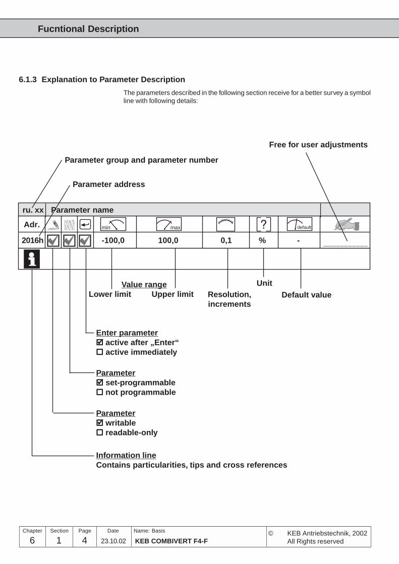
6 1Name: Basis
KEB COMBIVERT F4-F4 23.10.02
Fucntional Description
© KEB Antriebstechnik, 2002All Rights reserved
Chapter Section Page Date
Adr. min max default
6.1.3 Explanation to Parameter Description
The parameters described in the following section receive for a better survey a symbolline with following details:
ru. xx Parameter name
Parameter group and parameter number
Parameter address
Parameter""""" writable##### readable-only
Parameter""""" set-programmable##### not programmable
Enter parameter""""" active after „Enter“##### active immediately
Value rangeLower limit Upper limit Resolution,
increments
UnitDefault value
Information lineContains particularities, tips and cross references
Free for user adjustments
-100,0 100,0 0,1 % -2016h
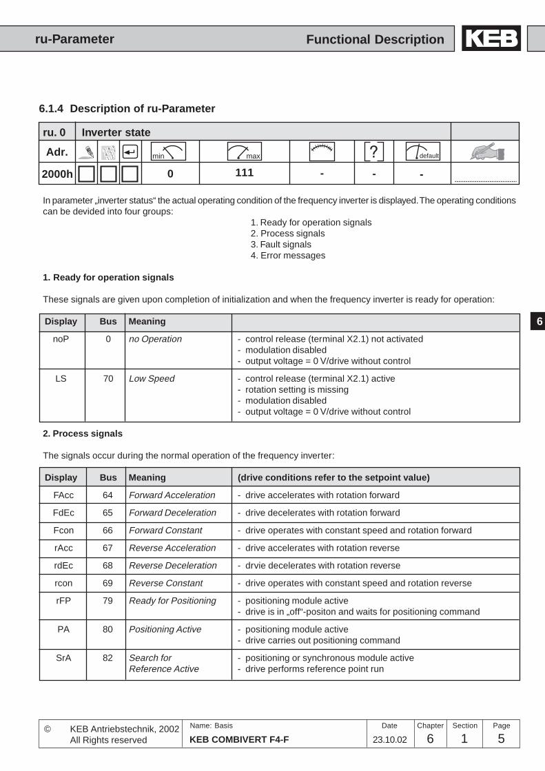
56 1 523.10.02KEB COMBIVERT F4-FName: Basis
6
Functional Description
© KEB Antriebstechnik, 2002All Rights reserved
Chapter Section PageDate
Adr. min max default
2000h 0 111 - - -
6.1.4 Description of ru-Parameter
ru. 0 Inverter state
ru-Parameter
In parameter „inverter status“ the actual operating condition of the frequency inverter is displayed. The operating conditionscan be devided into four groups:
1. Ready for operation signals2. Process signals3. Fault signals4. Error messages
1. Ready for operation signals
These signals are given upon completion of initialization and when the frequency inverter is ready for operation:
Display Bus Meaning
noP 0 no Operation - control release (terminal X2.1) not activated- modulation disabled- output voltage = 0 V/drive without control
LS 70 Low Speed - control release (terminal X2.1) active- rotation setting is missing- modulation disabled- output voltage = 0 V/drive without control
2. Process signals
The signals occur during the normal operation of the frequency inverter:
Display Bus Meaning (drive conditions refer to the setpoint value)
FAcc 64 Forward Acceleration - drive accelerates with rotation forward
FdEc 65 Forward Deceleration - drive decelerates with rotation forward
Fcon 66 Forward Constant - drive operates with constant speed and rotation forward
rAcc 67 Reverse Acceleration - drive accelerates with rotation reverse
rdEc 68 Reverse Deceleration - drvie decelerates with rotation reverse
rcon 69 Reverse Constant - drive operates with constant speed and rotation reverse
rFP 79 Ready for Positioning - positioning module active- drive is in „off“-positon and waits for positioning command
PA 80 Positioning Active - positioning module active- drive carries out positioning command
SrA 82 Search for - positioning or synchronous module activeReference Active - drive performs reference point run
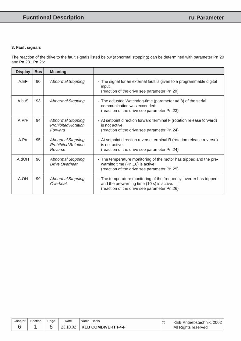
6 1Name: Basis
KEB COMBIVERT F4-F6 23.10.02
Fucntional Description
© KEB Antriebstechnik, 2002All Rights reserved
Chapter Section Page Date
ru-Parameter
3. Fault signals
The reaction of the drive to the fault signals listed below (abnormal stopping) can be determined with parameter Pn.20and Pn.23...Pn.26:
Display Bus Meaning
A.EF 90 Abnormal Stopping - The signal for an external fault is given to a programmable digitalinput.(reaction of the drive see parameter Pn.20)
A.buS 93 Abnormal Stopping - The adjusted Watchdog-time (parameter ud.8) of the serialcommunication was exceeded.(reaction of the drive see parameter Pn.23)
A.PrF 94 Abnormal Stopping - At setpoint direction forward terminal F (rotation release forward)Prohibited Rotation is not active.Forward (reaction of the drive see parameter Pn.24)
A.Prr 95 Abnormal Stopping - At setpoint direction reverse terminal R (rotation release reverse)Prohibited Rotation is not active.Reverse (reaction of the drive see parameter Pn.24)
A.dOH 96 Abnormal Stopping - The temperature monitoring of the motor has tripped and the pre-Drive Overheat warning time (Pn.16) is active.
(reaction of the drive see parameter Pn.25)
A.OH 99 Abnormal Stopping - The temperature monitoring of the frequency inverter has trippedOverheat and the prewarning time (10 s) is active.
(reaction of the drive see parameter Pn.26)
76 1 723.10.02KEB COMBIVERT F4-FName: Basis
6
Functional Description
© KEB Antriebstechnik, 2002All Rights reserved
Chapter Section PageDate
4. Error messages
Errors cause the immediate deactivation of the modulation and the generation of corresponding error messages (seetable). Before carrying out a restart remove the the error first and then actuate reset.
Display Bus Meaning
E.OP 1 Error Overpotential - The DC-link voltage has exceeded the permissible value.
E.UP 2 Error Underpotential - The DC-link voltage has fallen below the permissible value.
E.OC 4 Error Overcurrent - The output current has exceeded the permissible value.
E.OH 8 Error Overheat - The temperature monitoring of the frequency inverter has tripped and theprewarning time (10s) is expired.
E.dOH 9 Error Drive Overheat - The temperature monitoring of the motor has tripped and the prewarning time(Pn.16) is expired.
E.nOH 36 Error no Overheat - Overtemperature error no longer exists, the error messages (E.OH / E.dOH)can be reset and the frequency inverter restarted.
E.OL 16 Error Overload - The operation of the frequency inverter in the overload range has exceededthe permissible time (see overload characteristic in the Instruction ManualPart 2).
E.OL2 53 Error Overload 2 - Same meaning as E.OL, but occurs only in the lower frequency range (<3 Hz)(see overload characteristic in the Instruction Manual Part 2).
E.nOL 17 Error no Overload - After the cooling down phase the overload error (E.OL or E.OL2) no longerexists, the error message can be reset and the frequency inverter restarted.
E.buS 18 Error Bus - The adjusted Watchdog-time (parameter ud.8) of the serial communicationhas been exceeded (only at parameter Pn.23 = 0).
E.LSF 15 Error Load Shunt - After switching on the frequency inverter the input voltage is too low or theload shunt relay is not switching (monitoring with load shunt relay notavailable for all unit sizes).
E.EF 31 Error External Fault - The signal for an external error is given to a programmable digital input (onlyat parameter Pn.20 = 0).
E.SEt 39 Error Set - Set selection error: selected parameter set is locked (see parameter Fr.3)
E.PrF 46 Error Prohibited - At setpoint rotation forward terminal F (rotation release forward) is not active(only at parameter Pn.24 = 0).
E.Prr 47 Error Prohibited - At setpoint rotation reverse terminal R (rotation release reverse) is not active(only at parameter Pn.24 = 0).
E.dSP 51 Error Digital Signal - Processor - errorProcessor
E.Hyb 52 Error Hybrid - Control card error: carry out Power-on reset; if the error message continuesto show, the error can be removed only in the factory.
E.PuC 49 Error Power Unit - Control card error: carry out Power-on reset; if the error message continuesto show, the error can be removed only in the factory.
E.SLF 110 Error Software Limit - Selection of setpoint position outside the adjusted software limit at rotationforward (also see parameter Pc.4...Pc.6 positioning module)
E.SLr 111 Error Software Limit - Selection of setpoint position outside the adjusted software limit at rotationreverse (also see parameter Pc.7...Pc.9 positioning module)
ru-Parameter
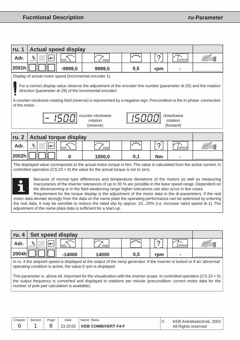
6 1Name: Basis
KEB COMBIVERT F4-F8 23.10.02
Fucntional Description
© KEB Antriebstechnik, 2002All Rights reserved
Chapter Section Page Date
Adr. min max default
Adr. min max default
Adr. min max default
2001h 0,59999,5-9999,5 -
ru-Parameter
2002h 0,1 Nm -1000,00
2004h 0,5 -14000-14000
ru. 1 Actual speed display
rpm
Display of actual motor speed (incremental encoder 1).
For a correct display value observe the adjustment of the encoder line number (parameter dr.25) and the rotationdirection (parameter dr.29) of the incremental encoder!
A counter-clockwise rotating field (reverse) is represented by a negative sign. Precondition is the in-phase connectionof the motor.
ru. 2 Actual torque display
The displayed value corresponds to the actual motor torque in Nm. The value is calculated from the active current. Incontrolled operation (CS.23 = 0) the value for the actual torque is set to zero.
Because of normal type differences and temperature deviations of the motors as well as measuringinaccuracies of the inverter tolerances of up to 30 % are possible in the base speed range. Dependent onthe dimensioning or in the field weakening range higher tolerances can also occur in few cases.Requirement for the torque display is the adjustment of the motor data in the dr-parameters. If the real
motor data deviate strongly from the data on the name plate the operating performance can be optimized by enteringthe real data. It may be sensible to reduce the rated slip by approx. 10...20% (i.e. increase rated speed dr.1). Theadjustment of the name plata data is sufficient for a start-up.
ru. 4 Set speed display
rpmIn ru. 4 the setpoint speed is displayed at the output of the ramp generator. If the inverter is locked or if an ‘abnormal’operating condition is active, the value 0 rpm is displayed.
This parameter is, above all, important for the visualization with the inverter scope. In controlled operation (CS.23 = 0)the output frequency is converted and displayed in rotations per minute (precondition: correct motor data for thenumber of pole pair calculation is available).
clowckwiserotation
(forward)
counter-clockwiserotation
(reverse)

96 1 923.10.02KEB COMBIVERT F4-FName: Basis
6
Functional Description
© KEB Antriebstechnik, 2002All Rights reserved
Chapter Section PageDate
Adr. min max default
Adr. min max default
Adr. min max default
Adr. min max default
ru-Parameter
2008h
2009h
200Ah
1 % -2000
0,1 A -0
0,1 A -0
2007h 1 % -2000
Adr. min max default
200Bh 1 V -999200
ru. 7 Actual inverter utilization
Display of the actual load related to the rated current of the inverter. Only positive values are displayed, thus adifferentiation between motoric and generatoric operation is not possible.
ru. 8 Peak inverter utilization
ru.8 allows the detection of short-time peak loads during an operating cycle. For that the highest detected value of ru.7is stored in ru.8. The peak value memory is cleared by pressing the keys UP or DOWN or by bus by writing any chosenvalue to the address of ru.8. The disconnection of the inverter also results in a clearing of the memory.
ru.9 Apparent current
Display of actual apparent curent. The maximum values depend on the size of the inverter.
ru.10 Active current
Display of the torque-forming active current. Precondition is the input of the motor data into dr.0...dr.4. The maximumvalues depend on the size of the inverter. With regard to limitations of the accuracy refer to ru.2. In controlled operation(CS.23 = 0) the display always shows 0.0 A.
unit-dependent
unit-dependent
Display of actual DC-link voltage. Typical values are fornormal operation: 230V-class approx. 300-330V in case of fault (E.OP): 230V-class approx.390V
400V-class approx. 530-620V 400V-class approx.800V
ru.11 Actual DC voltage
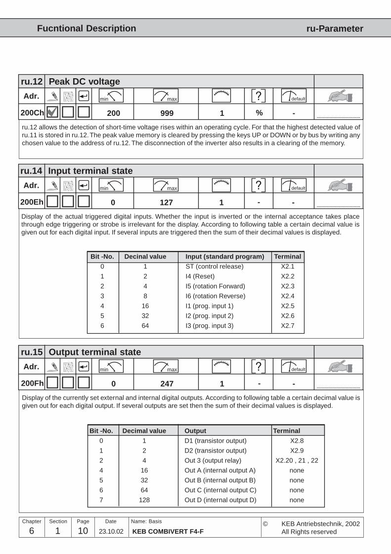
6 1Name: Basis
KEB COMBIVERT F4-F10 23.10.02
Fucntional Description
© KEB Antriebstechnik, 2002All Rights reserved
Chapter Section Page Date
Adr. min max default
Adr. min max default
Adr. min max default
200Ch 1 % -999200
200Eh 1 - -1270
ru-Parameter
200Fh 1 - -2470
ru.15 Output terminal state
Display of the currently set external and internal digital outputs. According to following table a certain decimal value isgiven out for each digital output. If several outputs are set then the sum of their decimal values is displayed.
Bit -No. Decimal value Output Terminal
0 1 D1 (transistor output) X2.8
1 2 D2 (transistor output) X2.9
2 4 Out 3 (output relay) X2.20 , 21 , 22
4 16 Out A (internal output A) none
5 32 Out B (internal output B) none
6 64 Out C (internal output C) none
7 128 Out D (internal output D) none
ru.12 Peak DC voltage
ru.12 allows the detection of short-time voltage rises within an operating cycle. For that the highest detected value ofru.11 is stored in ru.12. The peak value memory is cleared by pressing the keys UP or DOWN or by bus by writing anychosen value to the address of ru.12. The disconnection of the inverter also results in a clearing of the memory.
ru.14 Input terminal state
Display of the actual triggered digital inputs. Whether the input is inverted or the internal acceptance takes placethrough edge triggering or strobe is irrelevant for the display. According to following table a certain decimal value isgiven out for each digital input. If several inputs are triggered then the sum of their decimal values is displayed.
Bit -No. Decinal value Input (standard program) Terminal
0 1 ST (control release) X2.1
1 2 I4 (Reset) X2.2
2 4 I5 (rotation Forward) X2.3
3 8 I6 (rotation Reverse) X2.4
4 16 I1 (prog. input 1) X2.5
5 32 I2 (prog. input 2) X2.6
6 64 I3 (prog. input 3) X2.7
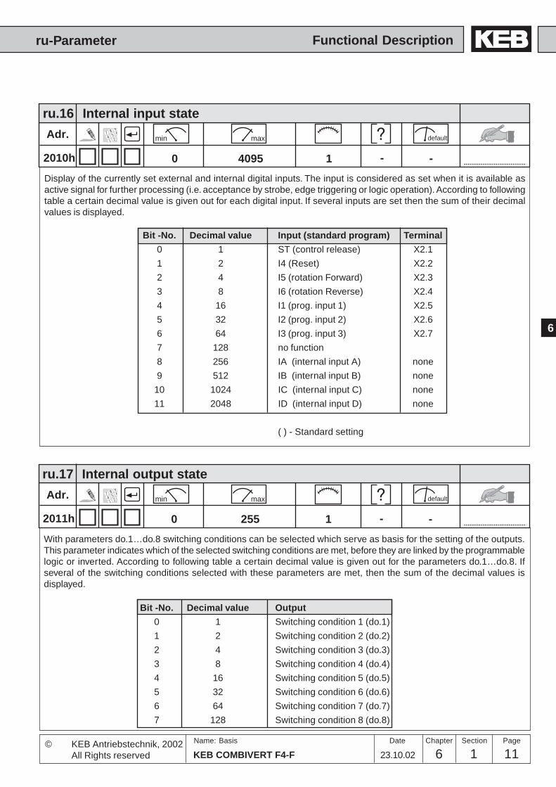
116 1 1123.10.02KEB COMBIVERT F4-FName: Basis
6
Functional Description
© KEB Antriebstechnik, 2002All Rights reserved
Chapter Section PageDate
Adr. min max default
ru-Parameter
2010h 1 - -40950
Adr. min max default
2011h 1 - -2550
ru.16 Internal input state
Display of the currently set external and internal digital inputs. The input is considered as set when it is available asactive signal for further processing (i.e. acceptance by strobe, edge triggering or logic operation). According to followingtable a certain decimal value is given out for each digital input. If several inputs are set then the sum of their decimalvalues is displayed.
Bit -No. Decimal value Input (standard program) Terminal
0 1 ST (control release) X2.1
1 2 I4 (Reset) X2.2
2 4 I5 (rotation Forward) X2.3
3 8 I6 (rotation Reverse) X2.4
4 16 I1 (prog. input 1) X2.5
5 32 I2 (prog. input 2) X2.6
6 64 I3 (prog. input 3) X2.7
7 128 no function
8 256 IA (internal input A) none
9 512 IB (internal input B) none
10 1024 IC (internal input C) none
11 2048 ID (internal input D) none
( ) - Standard setting
ru.17 Internal output state
With parameters do.1…do.8 switching conditions can be selected which serve as basis for the setting of the outputs.This parameter indicates which of the selected switching conditions are met, before they are linked by the programmablelogic or inverted. According to following table a certain decimal value is given out for the parameters do.1…do.8. Ifseveral of the switching conditions selected with these parameters are met, then the sum of the decimal values isdisplayed.
Bit -No. Decimal value Output
0 1 Switching condition 1 (do.1)
1 2 Switching condition 2 (do.2)
2 4 Switching condition 3 (do.3)
3 8 Switching condition 4 (do.4)
4 16 Switching condition 5 (do.5)
5 32 Switching condition 6 (do.6)
6 64 Switching condition 7 (do.7)
7 128 Switching condition 8 (do.8)
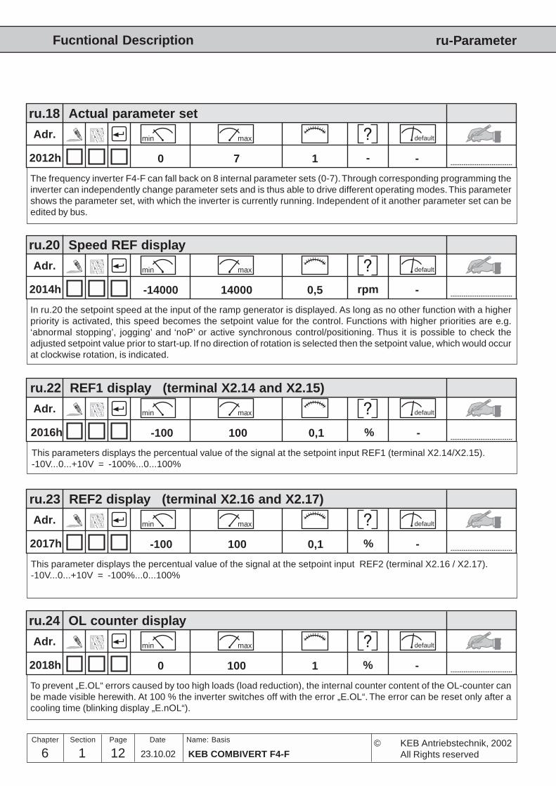
6 1Name: Basis
KEB COMBIVERT F4-F12 23.10.02
Fucntional Description
© KEB Antriebstechnik, 2002All Rights reserved
Chapter Section Page Date
Adr. min max default
Adr. min max default
Adr. min max default
Adr. min max default
Adr. min max default
2012h 1 - -70
2014h 0,5 -14000-14000
2016h 0,1 % -100-100
2017h 0,1 % -100-100
2018h 1 % -1000
ru-Parameter
ru.24 OL counter display
To prevent „E.OL“ errors caused by too high loads (load reduction), the internal counter content of the OL-counter canbe made visible herewith. At 100 % the inverter switches off with the error „E.OL“. The error can be reset only after acooling time (blinking display „E.nOL“).
ru.18 Actual parameter set
The frequency inverter F4-F can fall back on 8 internal parameter sets (0-7). Through corresponding programming theinverter can independently change parameter sets and is thus able to drive different operating modes. This parametershows the parameter set, with which the inverter is currently running. Independent of it another parameter set can beedited by bus.
ru.22 REF1 display (terminal X2.14 and X2.15)
This parameters displays the percentual value of the signal at the setpoint input REF1 (terminal X2.14/X2.15).-10V...0...+10V = -100%...0...100%
ru.23 REF2 display (terminal X2.16 and X2.17)
This parameter displays the percentual value of the signal at the setpoint input REF2 (terminal X2.16 / X2.17).-10V...0...+10V = -100%...0...100%
ru.20 Speed REF display
In ru.20 the setpoint speed at the input of the ramp generator is displayed. As long as no other function with a higherpriority is activated, this speed becomes the setpoint value for the control. Functions with higher priorities are e.g.‘abnormal stopping’, jogging’ and ‘noP’ or active synchronous control/positioning. Thus it is possible to check theadjusted setpoint value prior to start-up. If no direction of rotation is selected then the setpoint value, which would occurat clockwise rotation, is indicated.
rpm
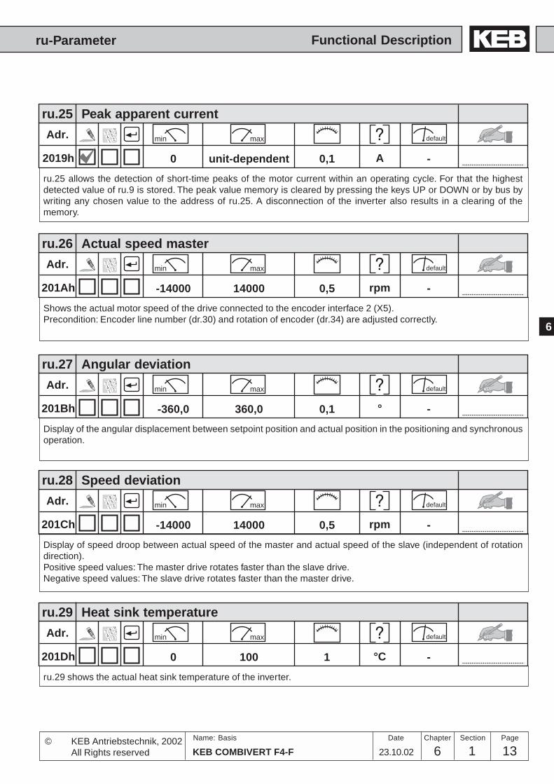
136 1 1323.10.02KEB COMBIVERT F4-FName: Basis
6
Functional Description
© KEB Antriebstechnik, 2002All Rights reserved
Chapter Section PageDate
Adr. min max default
Adr. min max default
Adr. min max default
2019h 0,1 A -0
Adr. min max default
201Bh 0,1 ° -360,0-360,0
Adr. min max default
201Ch 0,5 rpm -14000-14000
201Dh 1 °C -1000
ru-Parameter
ru.29 Heat sink temperature
ru.29 shows the actual heat sink temperature of the inverter.
201Ah
ru.26 Actual speed master
0,5 rpm -14000-14000
Shows the actual motor speed of the drive connected to the encoder interface 2 (X5).Precondition: Encoder line number (dr.30) and rotation of encoder (dr.34) are adjusted correctly.
ru.25 Peak apparent current
ru.25 allows the detection of short-time peaks of the motor current within an operating cycle. For that the highestdetected value of ru.9 is stored. The peak value memory is cleared by pressing the keys UP or DOWN or by bus bywriting any chosen value to the address of ru.25. A disconnection of the inverter also results in a clearing of thememory.
ru.27 Angular deviation
Display of the angular displacement between setpoint position and actual position in the positioning and synchronousoperation.
ru.28 Speed deviation
Display of speed droop between actual speed of the master and actual speed of the slave (independent of rotationdirection).Positive speed values: The master drive rotates faster than the slave drive.Negative speed values: The slave drive rotates faster than the master drive.
unit-dependent
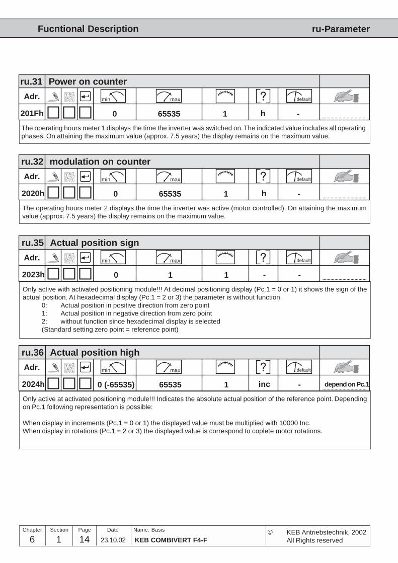
6 1Name: Basis
KEB COMBIVERT F4-F14 23.10.02
Fucntional Description
© KEB Antriebstechnik, 2002All Rights reserved
Chapter Section Page Date
Adr. min max default
Adr. min max default
Adr. min max default
201Fh 1 h -655350
2020h 1 h -655350
2023h 1 - -10
Adr. min max default
2024h 1 inc -655350 (-65535)
ru-Parameter
ru.35 Actual position sign
Only active with activated positioning module!!! At decimal positioning display (Pc.1 = 0 or 1) it shows the sign of theactual position. At hexadecimal display (Pc.1 = 2 or 3) the parameter is without function.
0: Actual position in positive direction from zero point1: Actual position in negative direction from zero point2: without function since hexadecimal display is selected(Standard setting zero point = reference point)
ru.31 Power on counter
The operating hours meter 1 displays the time the inverter was switched on. The indicated value includes all operatingphases. On attaining the maximum value (approx. 7.5 years) the display remains on the maximum value.
ru.32 modulation on counter
The operating hours meter 2 displays the time the inverter was active (motor controlled). On attaining the maximumvalue (approx. 7.5 years) the display remains on the maximum value.
ru.36 Actual position high
Only active at activated positioning module!!! Indicates the absolute actual position of the reference point. Dependingon Pc.1 following representation is possible:
When display in increments (Pc.1 = 0 or 1) the displayed value must be multiplied with 10000 Inc.When display in rotations (Pc.1 = 2 or 3) the displayed value is correspond to coplete motor rotations.
depend on Pc.1
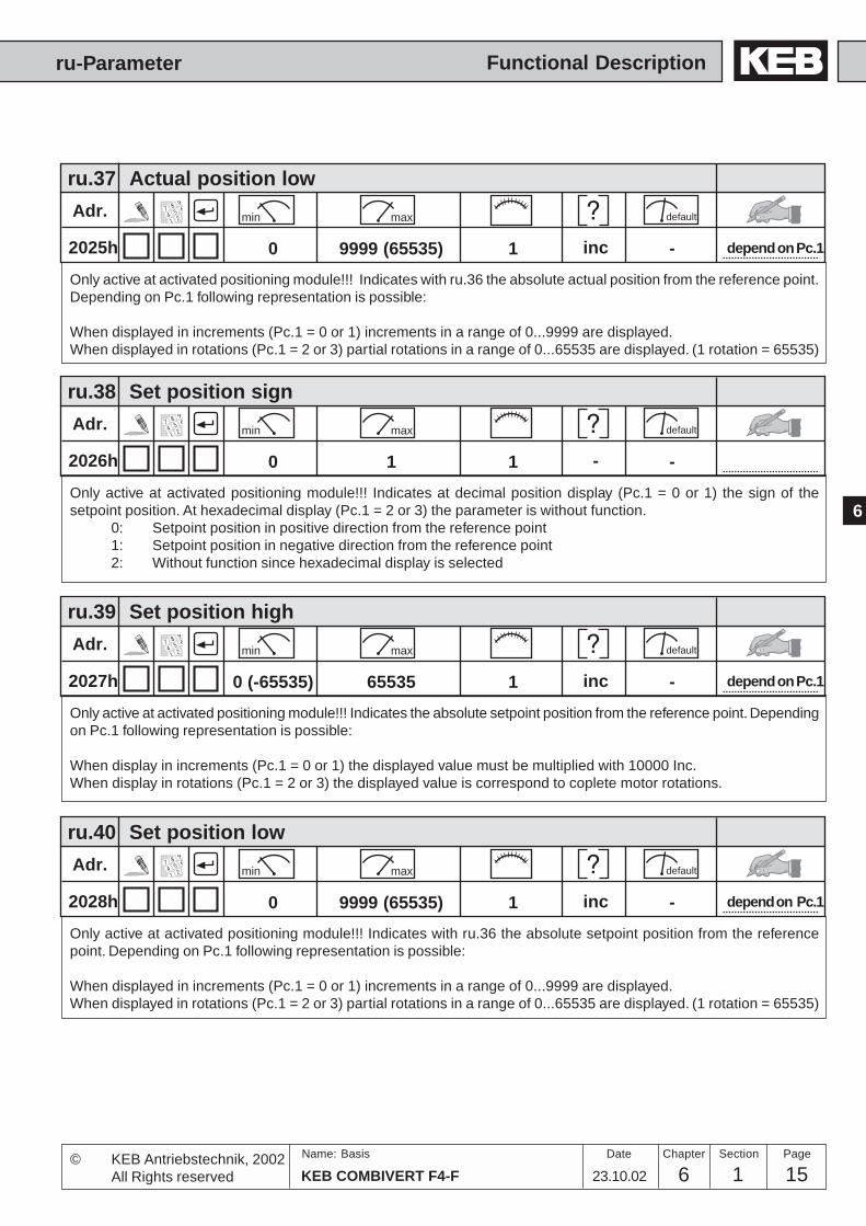
156 1 1523.10.02KEB COMBIVERT F4-FName: Basis
6
Functional Description
© KEB Antriebstechnik, 2002All Rights reserved
Chapter Section PageDate
Only active at activated positioning module!!! Indicates with ru.36 the absolute setpoint position from the referencepoint. Depending on Pc.1 following representation is possible:
When displayed in increments (Pc.1 = 0 or 1) increments in a range of 0...9999 are displayed.When displayed in rotations (Pc.1 = 2 or 3) partial rotations in a range of 0...65535 are displayed. (1 rotation = 65535)
2025h 1 inc9999 (65535)0
Adr. min max default
Adr. min max default
2026h 1 - -10
Adr. min max default
2027h 1 inc -655350 (-65535)
Adr. min max default
2028h 1 inc9999 (65535)0
ru-Parameter
-
ru.37 Actual position low
Only active at activated positioning module!!! Indicates with ru.36 the absolute actual position from the reference point.Depending on Pc.1 following representation is possible:
When displayed in increments (Pc.1 = 0 or 1) increments in a range of 0...9999 are displayed.When displayed in rotations (Pc.1 = 2 or 3) partial rotations in a range of 0...65535 are displayed. (1 rotation = 65535)
ru.38 Set position sign
ru.39 Set position high
Only active at activated positioning module!!! Indicates the absolute setpoint position from the reference point. Dependingon Pc.1 following representation is possible:
When display in increments (Pc.1 = 0 or 1) the displayed value must be multiplied with 10000 Inc.When display in rotations (Pc.1 = 2 or 3) the displayed value is correspond to coplete motor rotations.
depend on Pc.1
depend on Pc.1-
ru.40 Set position low
Only active at activated positioning module!!! Indicates at decimal position display (Pc.1 = 0 or 1) the sign of thesetpoint position. At hexadecimal display (Pc.1 = 2 or 3) the parameter is without function.
0: Setpoint position in positive direction from the reference point1: Setpoint position in negative direction from the reference point2: Without function since hexadecimal display is selected
depend on Pc.1
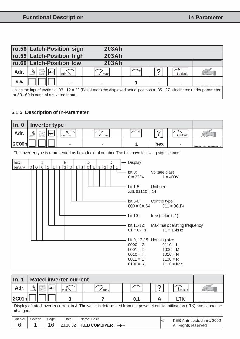
6 1Name: Basis
KEB COMBIVERT F4-F16 23.10.02
Fucntional Description
© KEB Antriebstechnik, 2002All Rights reserved
Chapter Section Page Date
Adr. min max default
Adr. min max default
2C01h 0,1 A LTK?0
2C00h 1 hex ---
In-Parameter
6.1.5 Description of In-Parameter
In. 0 Inverter type
In. 1 Rated inverter current
Display of rated inverter current in A. The value is determined from the power circuit identification (LTK) and cannot bechanged.
The inverter type is represented as hexadecimal number. The bits have following significance:
hex 1 E D D Displaybinary 0 0 0 1 1 1 1 0 1 1 0 1 1 1 0 1
bit 0: Voltage class0 = 230V 1 = 400V
bit 1-5: Unit sizez.B. 01110 = 14
bit 6-8: Control type000 = 0A.S4 011 = 0C.F4
bit 10: free (default=1)
bit 11-12: Maximal operating frequency01 = 8kHz 11 = 16kHz
bit 9, 13-15: Housing size0000 = G 0110 = L0001 = D 1000 = M0010 = H 1010 = N0011 = E 1100 = R0100 = K 1110 = free
Adr. min max default
-
ru.58 Latch-Position sign 203Ahru.59 Latch-Position high 203Ahru.60 Latch-Position low 203Ah
Using the input function di.03...12 = 23 (Posi-Latch) the displayed actual position ru.35...37 is indicated under parameterru.58...60 in case of activated input.
s.a. --- 1
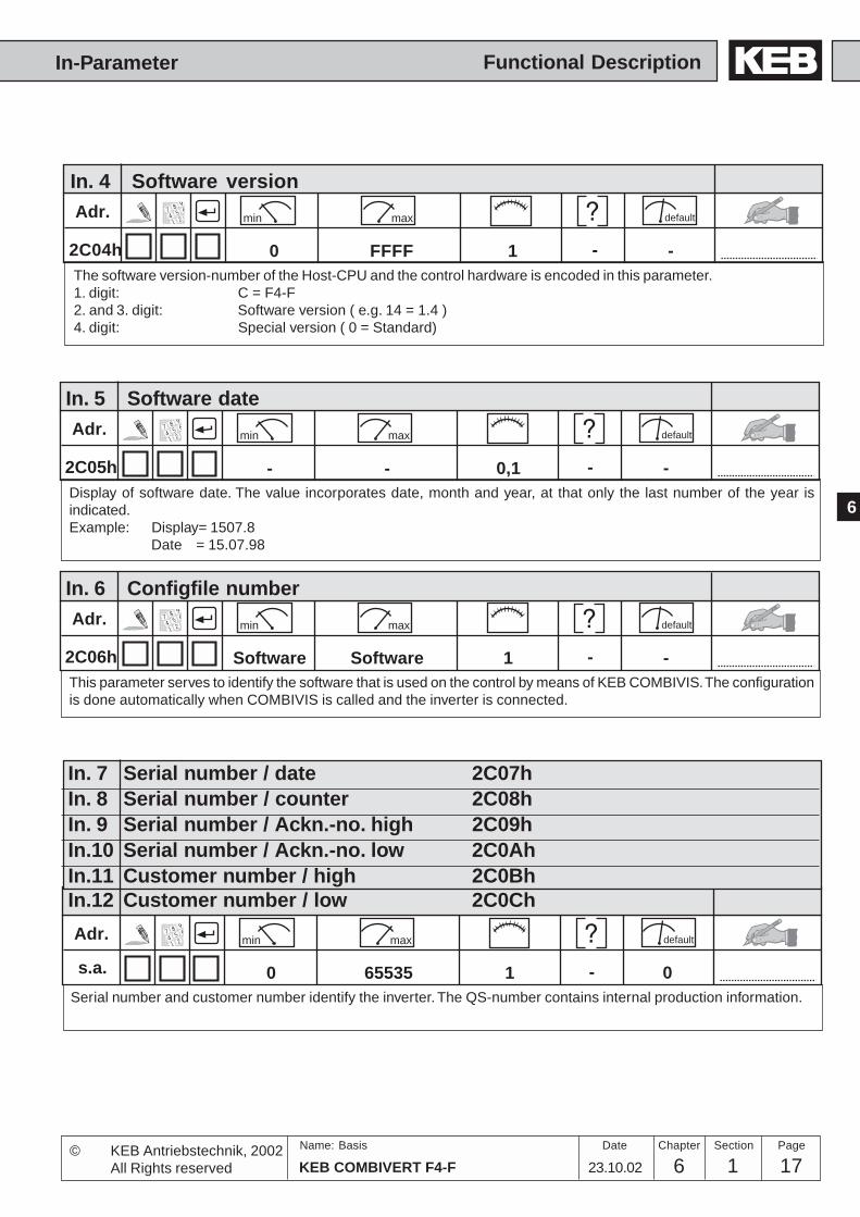
176 1 1723.10.02KEB COMBIVERT F4-FName: Basis
6
Functional Description
© KEB Antriebstechnik, 2002All Rights reserved
Chapter Section PageDate
Adr. min max default
2C04h
Adr. min max default
2C05h
Adr. min max default
2C06h
1 - -FFFF0
0,1 - ---
1 - -SoftwareSoftware
Adr. min max default
1 - 0655350
In-Parameter
The software version-number of the Host-CPU and the control hardware is encoded in this parameter.1. digit: C = F4-F2. and 3. digit: Software version ( e.g. 14 = 1.4 )4. digit: Special version ( 0 = Standard)
In. 4 Software version
Display of software date. The value incorporates date, month and year, at that only the last number of the year isindicated.Example: Display= 1507.8
Date = 15.07.98
In. 5 Software date
This parameter serves to identify the software that is used on the control by means of KEB COMBIVIS. The configurationis done automatically when COMBIVIS is called and the inverter is connected.
In. 6 Configfile number
s.a.
Serial number and customer number identify the inverter. The QS-number contains internal production information.
In. 7 Serial number / date 2C07hIn. 8 Serial number / counter 2C08hIn. 9 Serial number / Ackn.-no. high 2C09hIn.10 Serial number / Ackn.-no. low 2C0AhIn.11 Customer number / high 2C0BhIn.12 Customer number / low 2C0Ch
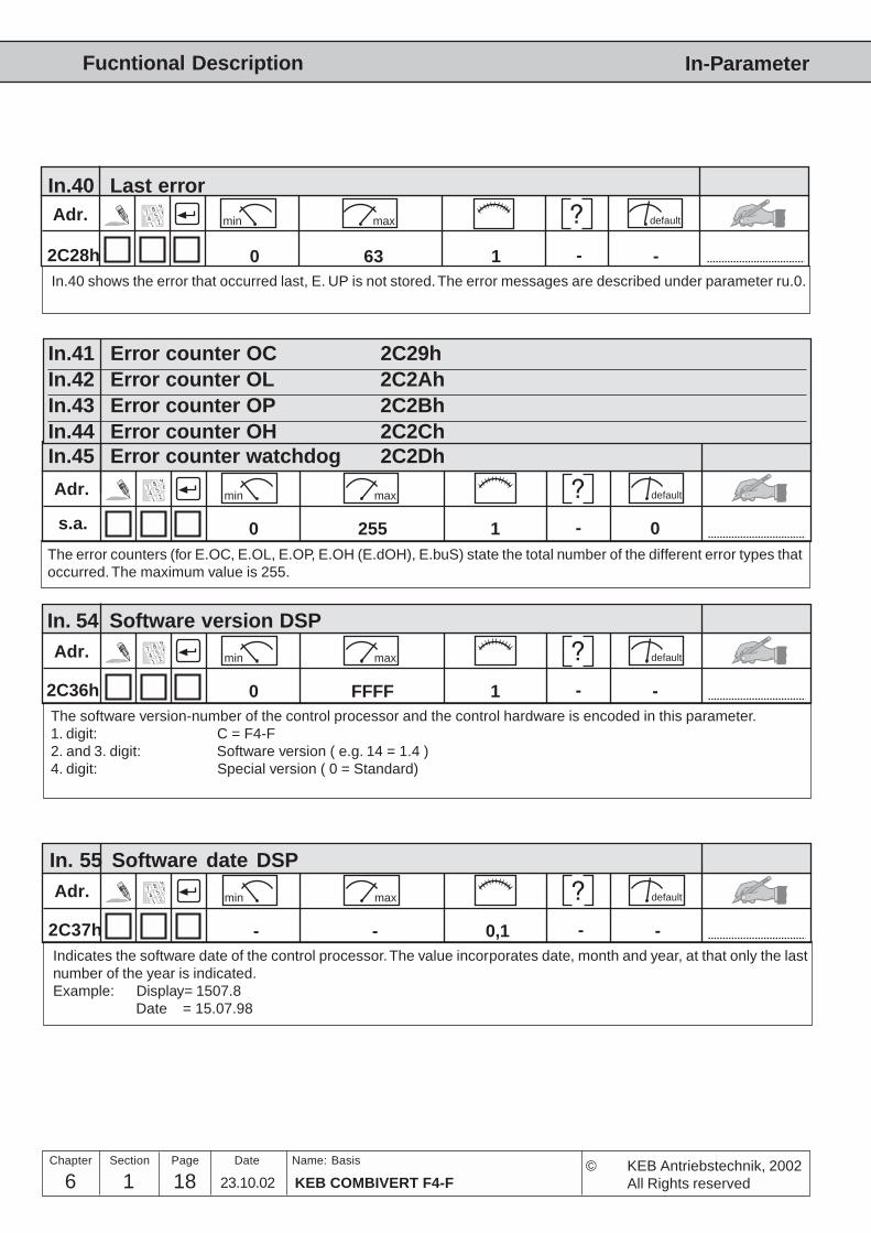
6 1Name: Basis
KEB COMBIVERT F4-F18 23.10.02
Fucntional Description
© KEB Antriebstechnik, 2002All Rights reserved
Chapter Section Page Date
Adr. min max default
1 - 02550
Adr. min max default
2C28h 1 - -630
Adr. min max default
2C36h 1 - -FFFF0
Adr. min max default
2C37h 0,1 - ---
In-Parameter
In.41 Error counter OC 2C29hIn.42 Error counter OL 2C2AhIn.43 Error counter OP 2C2BhIn.44 Error counter OH 2C2ChIn.45 Error counter watchdog 2C2Dh
The error counters (for E.OC, E.OL, E.OP, E.OH (E.dOH), E.buS) state the total number of the different error types thatoccurred. The maximum value is 255.
s.a.
In.40 shows the error that occurred last, E. UP is not stored. The error messages are described under parameter ru.0.
In.40 Last error
The software version-number of the control processor and the control hardware is encoded in this parameter.1. digit: C = F4-F2. and 3. digit: Software version ( e.g. 14 = 1.4 )4. digit: Special version ( 0 = Standard)
In. 54 Software version DSP
Indicates the software date of the control processor. The value incorporates date, month and year, at that only the lastnumber of the year is indicated.Example: Display= 1507.8
Date = 15.07.98
In. 55 Software date DSP

196 1 1923.10.02KEB COMBIVERT F4-FName: Basis
6
Functional Description
© KEB Antriebstechnik, 2002All Rights reserved
Chapter Section PageDate
In-Parameter
Adr. min max default
-
In.60 Last error 2C3ChIn.61 Last error 2C3DhIn.62 Last error 2C3EhIn.63 Last error 2C3Fh
For a better error diagnosis the last 4 errors triggered are displayed.
s.a. --- 1

6 1Name: Basis
KEB COMBIVERT F4-F20 23.10.02
Fucntional Description
© KEB Antriebstechnik, 2002All Rights reserved
Chapter Section Page Date
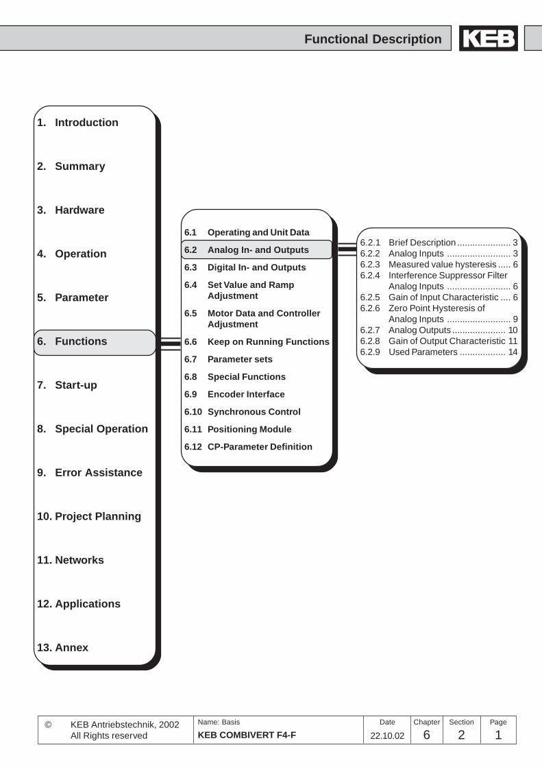
6 2 1KEB COMBIVERT F4-F
Name: Basis
22.10.02
Functional Description
Chapter Section PageDate© KEB Antriebstechnik, 2002All Rights reserved
6.1 Operating and Unit Data
6.2 Analog In- and Outputs
6.3 Digital In- and Outputs
6.4 Set Value and RampAdjustment
6.5 Motor Data and ControllerAdjustment
6.6 Keep on Running Functions
6.7 Parameter sets
6.8 Special Functions
6.9 Encoder Interface
6.10 Synchronous Control
6.11 Positioning Module
6.12 CP-Parameter Definition
1. Introduction
2. Summary
3. Hardware
4. Operation
5. Parameter
6. Functions
7. Start-up
8. Special Operation
9. Error Assistance
10. Project Planning
11. Networks
12. Applications
13. Annex
6.2.1 Brief Description ..................... 36.2.2 Analog Inputs ......................... 36.2.3 Measured value hysteresis ..... 66.2.4 Interference Suppressor Filter
Analog Inputs ......................... 66.2.5 Gain of Input Characteristic .... 66.2.6 Zero Point Hysteresis of
Analog Inputs ......................... 96.2.7 Analog Outputs ..................... 106.2.8 Gain of Output Characteristic 116.2.9 Used Parameters .................. 14

2 26Name: Basis
KEB COMBIVERT F4-F22.10.02
Functional Description Analog In- and Outputs
Chapter Section Page Date © KEB Antriebstechnik, 2002All Rights reserved
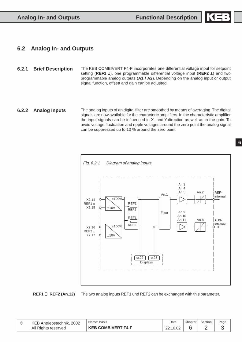
6 2 3KEB COMBIVERT F4-F
Name: Basis
22.10.02
Functional DescriptionAnalog In- and Outputs
Chapter Section PageDate© KEB Antriebstechnik, 2002All Rights reserved
6
X2.14REF1 ±
X2.15
REF-internal
X2.16REF2 ±
X2.17
AUX-internal
±100%
±10V
±100%
±10V
An.1
Filter
An.3An.4An.5
An.9An.10An.11
An.2
An.8
ru.22 ru.23
6.2.1 Brief Description
6.2 Analog In- and Outputs
The KEB COMBIVERT F4-F incorporates one differential voltage input for setpointsetting (REF1 ±), one programmable differential voltage input (REF2 ±) and twoprogrammable analog outputs (A1 / A2). Depending on the analog input or outputsignal function, offsett and gain can be adjusted.
6.2.2 Analog Inputs The analog inputs of an digital filter are smoothed by means of averaging. The digitalsignals are now available for the characteric amplifiers. In the characteristic amplifierthe input signals can be influenced in X- and Y-direction as well as in the gain. Toavoid voltage fluctuation and ripple voltages around the zero point the analog signalcan be suppressed up to 10 % around the zero point.
Fig. 6.2.1 Diagram of analog inputs
Displays
REF1
REF1
REF2
REF2
The two analog inputs REF1 und REF2 can be exchanged with this parameter.REF1 ⇔⇔⇔⇔⇔ REF2 (An.12)
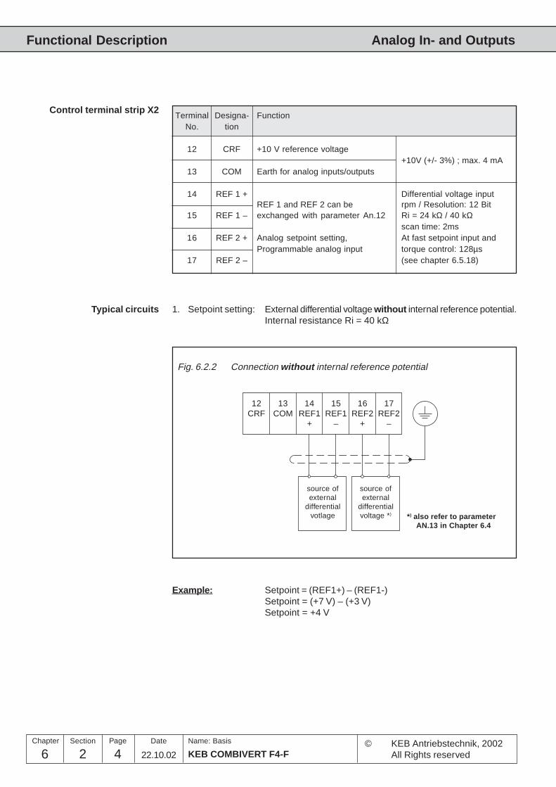
2 46Name: Basis
KEB COMBIVERT F4-F22.10.02
Functional Description Analog In- and Outputs
Chapter Section Page Date © KEB Antriebstechnik, 2002All Rights reserved
12 13 14 15 16 17CRF COM REF1 REF1 REF2 REF2
+ – + –
Control terminal strip X2
Typical circuits 1. Setpoint setting: External differential voltage without internal reference potential.Internal resistance Ri = 40 kΩ
source ofexternal
differentialvotlage
source ofexternal
differentialvoltage *)
Fig. 6.2.2 Connection without internal reference potential
*) also refer to parameterAN.13 in Chapter 6.4
Example: Setpoint = (REF1+) – (REF1-)Setpoint = (+7 V) – (+3 V)Setpoint = +4 V
Terminal Designa- FunctionNo. tion
12 CRF +10 V reference voltage+10V (+/- 3%) ; max. 4 mA
13 COM Earth for analog inputs/outputs
14 REF 1 + Differential voltage inputREF 1 and REF 2 can be rpm / Resolution: 12 Bit
15 REF 1 – exchanged with parameter An.12 Ri = 24 kΩ / 40 kΩscan time: 2ms
16 REF 2 + Analog setpoint setting, At fast setpoint input andProgrammable analog input torque control: 128µs
17 REF 2 – (see chapter 6.5.18)
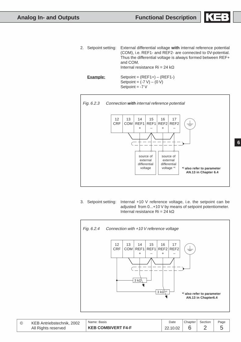
6 2 5KEB COMBIVERT F4-F
Name: Basis
22.10.02
Functional DescriptionAnalog In- and Outputs
Chapter Section PageDate© KEB Antriebstechnik, 2002All Rights reserved
6
12 13 14 15 16 17CRF COM REF1 REF1 REF2 REF2
+ – + –
12 13 14 15 16 17CRF COM REF1 REF1 REF2 REF2
+ – + –
3 kΩ
3 kΩ *)
2. Setpoint setting: External differential voltage with internal reference potential(COM), i.e. REF1- and REF2- are connected to 0V-potential.Thus the differential voltage is always formed between REF+and COM.Internal resistance Ri = 24 kΩ
Example: Setpoint = (REF1+) – (REF1-)Setpoint = (-7 V) – (0 V)Setpoint = -7 V
source ofexternal
differentialvoltage
source ofexternal
differentialvoltage *)
Fig. 6.2.3 Connection with internal reference potential
*) also refer to parameterAN.13 in Chapter 6.4
3. Setpoint setting: Internal +10 V reference voltage, i.e. the setpoint can beadjusted from 0...+10 V by means of setpoint potentiometer.Internal resistance Ri = 24 kΩ
Fig. 6.2.4 Connection with +10 V reference voltage
*) also refer to parameterAN.13 in Chapter6.4
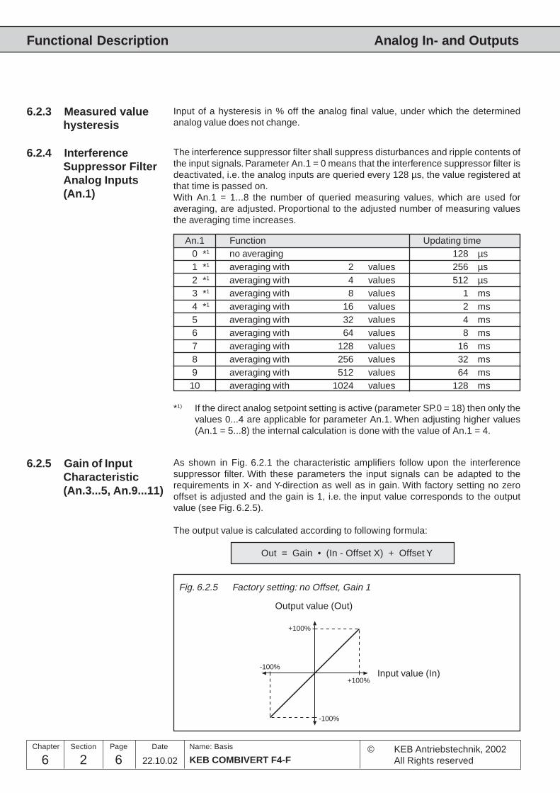
2 66Name: Basis
KEB COMBIVERT F4-F22.10.02
Functional Description Analog In- and Outputs
Chapter Section Page Date © KEB Antriebstechnik, 2002All Rights reserved
+100%
+100%
-100%
-100%
The interference suppressor filter shall suppress disturbances and ripple contents ofthe input signals. Parameter An.1 = 0 means that the interference suppressor filter isdeactivated, i.e. the analog inputs are queried every 128 µs, the value registered atthat time is passed on.With An.1 = 1...8 the number of queried measuring values, which are used foraveraging, are adjusted. Proportional to the adjusted number of measuring valuesthe averaging time increases.
6.2.4 InterferenceSuppressor FilterAnalog Inputs(An.1)
*1) If the direct analog setpoint setting is active (parameter SP.0 = 18) then only thevalues 0...4 are applicable for parameter An.1. When adjusting higher values(An.1 = 5...8) the internal calculation is done with the value of An.1 = 4.
6.2.5 Gain of InputCharacteristic(An.3...5, An.9...11)
As shown in Fig. 6.2.1 the characteristic amplifiers follow upon the interferencesuppressor filter. With these parameters the input signals can be adapted to therequirements in X- and Y-direction as well as in gain. With factory setting no zerooffset is adjusted and the gain is 1, i.e. the input value corresponds to the outputvalue (see Fig. 6.2.5).
The output value is calculated according to following formula:
Out = Gain • (In - Offset X) + Offset Y
Input value (In)
Output value (Out)
Fig. 6.2.5 Factory setting: no Offset, Gain 1
An.1 Function Updating time0 *1 no averaging 128 µs1 *1 averaging with 2 values 256 µs2 *1 averaging with 4 values 512 µs3 *1 averaging with 8 values 1 ms4 *1 averaging with 16 values 2 ms5 averaging with 32 values 4 ms6 averaging with 64 values 8 ms7 averaging with 128 values 16 ms8 averaging with 256 values 32 ms9 averaging with 512 values 64 ms10 averaging with 1024 values 128 ms
6.2.3 Measured valuehysteresis
Input of a hysteresis in % off the analog final value, under which the determinedanalog value does not change.
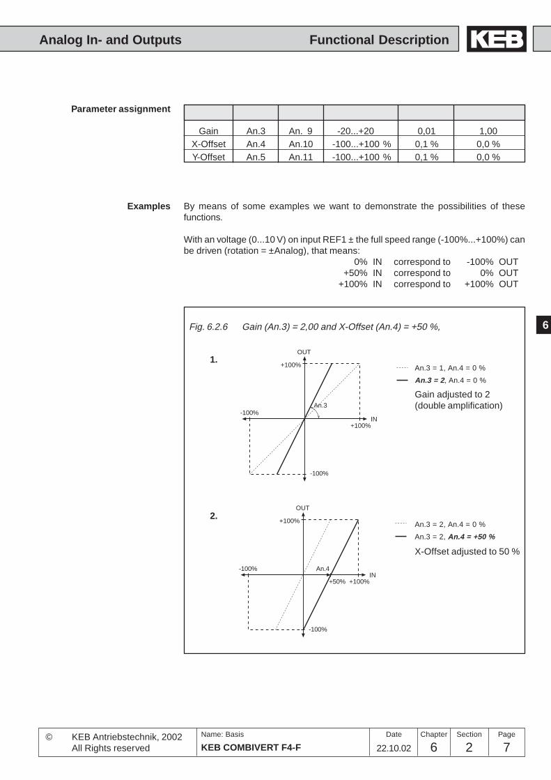
6 2 7KEB COMBIVERT F4-F
Name: Basis
22.10.02
Functional DescriptionAnalog In- and Outputs
Chapter Section PageDate© KEB Antriebstechnik, 2002All Rights reserved
6
Function REF1 ± REF2 ± Value range Resolution Default value
Gain An.3 An. 9 -20...+20 0,01 1,00X-Offset An.4 An.10 -100...+100 % 0,1 % 0,0 %Y-Offset An.5 An.11 -100...+100 % 0,1 % 0,0 %
+100%
+100%
-100%
-100%An.3
IN
OUT
+100%
+100%
-100%
-100% An.4
+50%IN
OUT
1.
2.
An.3 = 1, An.4 = 0 %
An.3 = 2, An.4 = 0 %
An.3 = 2, An.4 = 0 %
An.3 = 2, An.4 = +50 %
Parameter assignment
Examples
Fig. 6.2.6 Gain (An.3) = 2,00 and X-Offset (An.4) = +50 %,
By means of some examples we want to demonstrate the possibilities of thesefunctions.
With an voltage (0...10 V) on input REF1 ± the full speed range (-100%...+100%) canbe driven (rotation = ±Analog), that means:
0% IN correspond to -100% OUT+50% IN correspond to 0% OUT
+100% IN correspond to +100% OUT
Gain adjusted to 2(double amplification)
X-Offset adjusted to 50 %
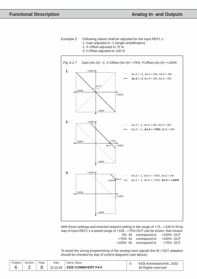
2 86Name: Basis
KEB COMBIVERT F4-F22.10.02
Functional Description Analog In- and Outputs
Chapter Section Page Date © KEB Antriebstechnik, 2002All Rights reserved
+100%
+100%
-100%
-100%
An.3
+100%
+100%
-100%
-100%
An.4
+75%
1.
2.
An.3 = +1, An.4 = 0%, An.5 = 0%
An.3 = -1, An.4 = 0%, An.5 = 0%
An.3 = -1, An.4 = 0%, An.5 = 0%
An.3 = -1, An.4 = +75%, An.5 = 0%
+100%
+100%
-100%
-100%
An.5+100%
3.An.3 = -1, An.4 = +75%, An.5 = 0%
An.3 = -1, An.4 = +75%, An.5 = +100%
Fig. 6.2.7 Gain (An.3)= -1, X-Offset (An.4)= +75%, Y-Offset (An.5)= +100%
Example 2: Following values shall be adjusted for the input REF1 ± :1. Gain adjusted to -1 (single amplification)2. X-Offset adjusted to 75 %3. Y-Offset adjusted to 100 %
With these settings and inverted setpoint setting in the range of +75...+100 % IN byway of input REF1 ± a speed range of +100...+75% OUT can be driven, that means:
0% IN correspond to +100% OUT+75% IN correspond to +100% OUT
+100% IN correspond to +75% OUT
To avoid the wrong programming of the analog input signals the IN / OUT adaptionshould be checked by way of control diagrams (see above).
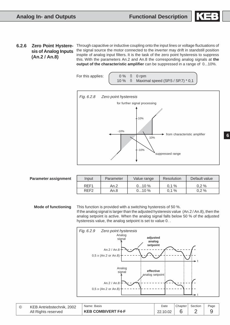
6 2 9KEB COMBIVERT F4-F
Name: Basis
22.10.02
Functional DescriptionAnalog In- and Outputs
Chapter Section PageDate© KEB Antriebstechnik, 2002All Rights reserved
6-10%
10%
10%
-10%
t
t
Through capacitive or inductive coupling onto the input lines or voltage fluctuations ofthe signal source the motor connected to the inverter may drift in standstill positioninspite of analog input filters. It is the task of the zero point hysteresis to suppressthis. With the parameters An.2 and An.8 the corresponding analog signals at theoutput of the characteristic amplifier can be suppressed in a range of 0...10%.
For this applies: 0 % = 0 rpm10 % = Maximal speed (SP.5 / SP.7) * 0,1
6.2.6 Zero Point Hystere-sis of Analog Inputs(An.2 / An.8)
This function is provided with a switching hysteresis of 50 %.If the analog signal is larger than the adjusted hysteresis value (An.2 / An.8), then theanalog setpoint is active. When the analog signal falls below 50 % of the adjustedhysteresis value, the analog setpoint is set to value 0. .
from characteristic amplifier
for further signal processing
suppressed range
Fig. 6.2.8 Zero point hysteresis
Fig. 6.2.9 Zero point hysteresis
Parameter assignment
Analogsignal
Analogsignal
adjustedanalog
setpoint
effectiveanalog setpoint
An.2 / An.8
0,5 x (An.2 or An.8)
An.2 / An.8
0,5 x (An.2 or An.8)
Mode of functioning
Input Parameter Value range Resolution Default value
REF1 An.2 0...10 % 0,1 % 0,2 %REF2 An.8 0...10 % 0,1 % 0,2 %
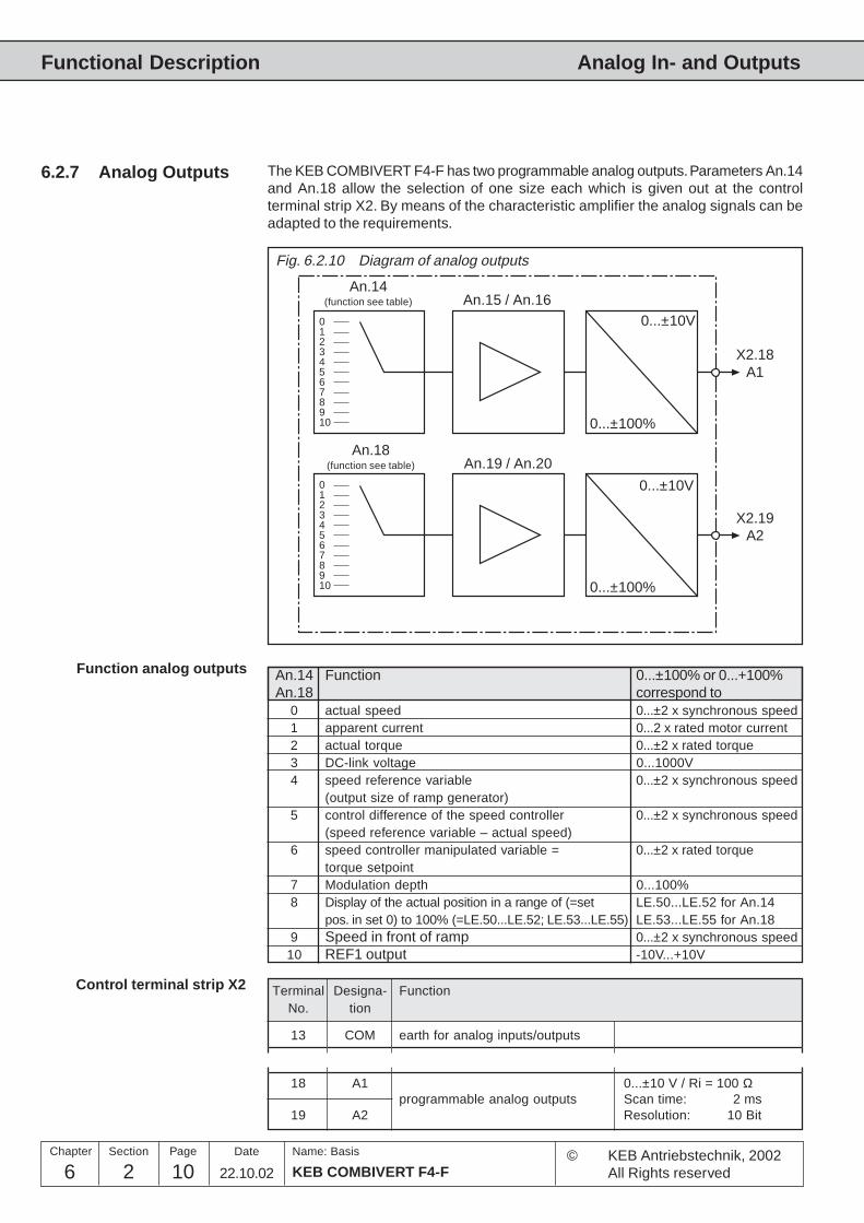
2 106Name: Basis
KEB COMBIVERT F4-F22.10.02
Functional Description Analog In- and Outputs
Chapter Section Page Date © KEB Antriebstechnik, 2002All Rights reserved
Terminal Designa- FunctionNo. tion
13 COM earth for analog inputs/outputs
18 A1 0...±10 V / Ri = 100 Ωprogrammable analog outputs Scan time: 2 ms
19 A2 Resolution: 10 Bit
An.14 Function 0...±100% or 0...+100%An.18 correspond to
0 actual speed 0...±2 x synchronous speed1 apparent current 0...2 x rated motor current2 actual torque 0...±2 x rated torque3 DC-link voltage 0...1000V4 speed reference variable 0...±2 x synchronous speed
(output size of ramp generator)5 control difference of the speed controller 0...±2 x synchronous speed
(speed reference variable – actual speed)6 speed controller manipulated variable = 0...±2 x rated torque
torque setpoint7 Modulation depth 0...100%8 Display of the actual position in a range of (=set LE.50...LE.52 for An.14
pos. in set 0) to 100% (=LE.50...LE.52; LE.53...LE.55) LE.53...LE.55 for An.189 Speed in front of ramp 0...±2 x synchronous speed
10 REF1 output -10V...+10V
The KEB COMBIVERT F4-F has two programmable analog outputs. Parameters An.14and An.18 allow the selection of one size each which is given out at the controlterminal strip X2. By means of the characteristic amplifier the analog signals can beadapted to the requirements.
6.2.7 Analog Outputs
012345678910
012345678910
Fig. 6.2.10 Diagram of analog outputs
An.14(function see table)
An.18(function see table)
An.15 / An.16
An.19 / An.20
0...±100%
0...±10V
0...±100%
0...±10V
X2.18A1
X2.19A2
Function analog outputs
Control terminal strip X2
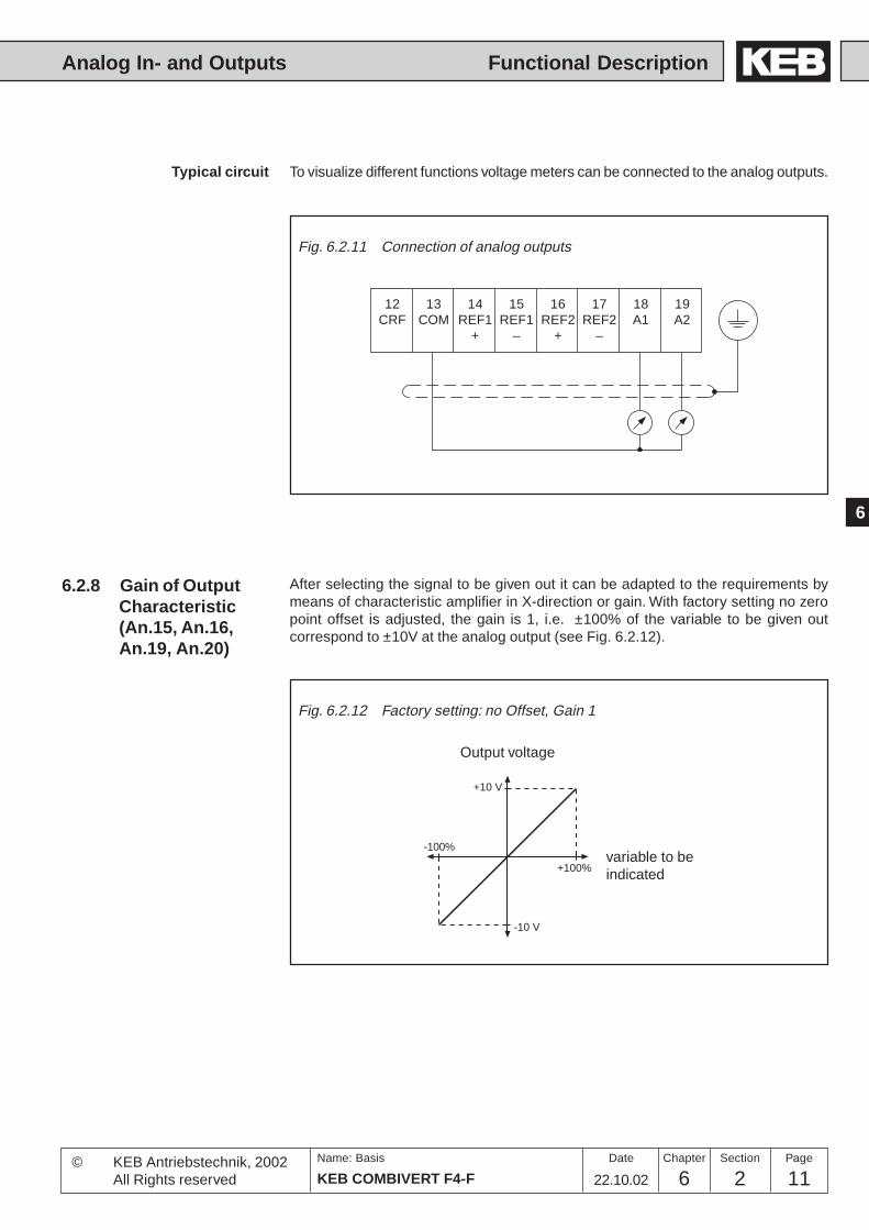
6 2 11KEB COMBIVERT F4-F
Name: Basis
22.10.02
Functional DescriptionAnalog In- and Outputs
Chapter Section PageDate© KEB Antriebstechnik, 2002All Rights reserved
6
12 13 14 15 16 17 18 19CRF COM REF1 REF1 REF2 REF2 A1 A2
+ – + –
Typical circuit To visualize different functions voltage meters can be connected to the analog outputs.
Fig. 6.2.11 Connection of analog outputs
+10 V
+100%
-10 V
-100%
6.2.8 Gain of OutputCharacteristic(An.15, An.16,An.19, An.20)
After selecting the signal to be given out it can be adapted to the requirements bymeans of characteristic amplifier in X-direction or gain. With factory setting no zeropoint offset is adjusted, the gain is 1, i.e. ±100% of the variable to be given outcorrespond to ±10V at the analog output (see Fig. 6.2.12).
variable to beindicated
Output voltage
Fig. 6.2.12 Factory setting: no Offset, Gain 1
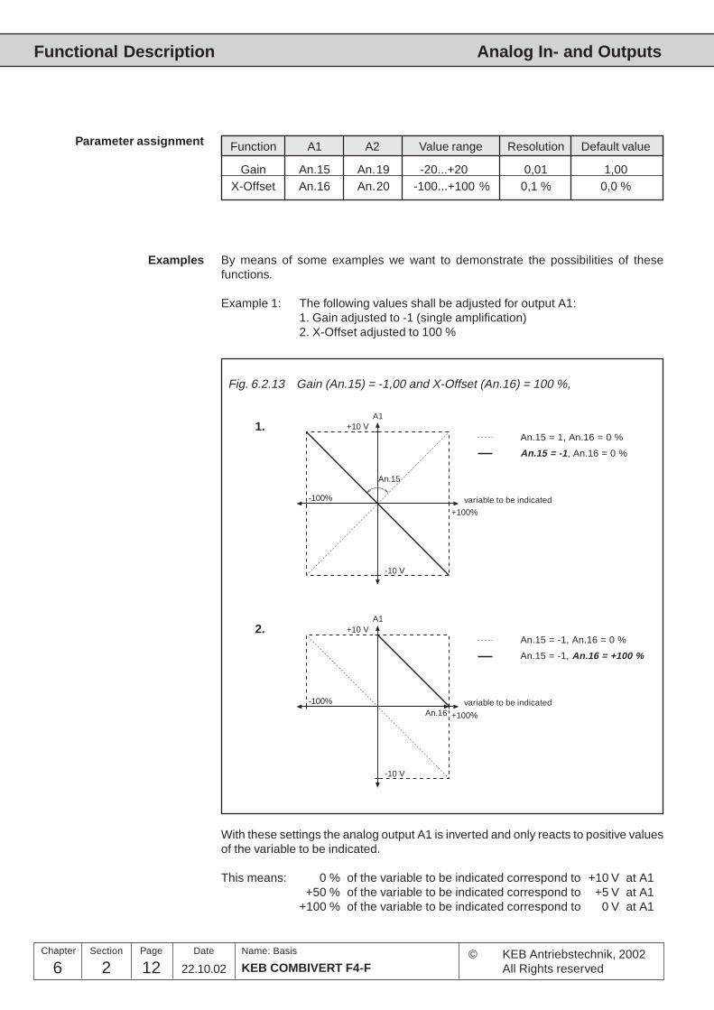
2 126Name: Basis
KEB COMBIVERT F4-F22.10.02
Functional Description Analog In- and Outputs
Chapter Section Page Date © KEB Antriebstechnik, 2002All Rights reserved
Parameter assignment Function A1 A2 Value range Resolution Default value
Gain An.15 An.19 -20...+20 0,01 1,00X-Offset An.16 An.20 -100...+100 % 0,1 % 0,0 %
+10 V
+100%
-10 V
-100%
An.15
An.15 = 1, An.16 = 0 %
An.15 = -1, An.16 = 0 %
With these settings the analog output A1 is inverted and only reacts to positive valuesof the variable to be indicated.
This means: 0 % of the variable to be indicated correspond to +10 V at A1+50 % of the variable to be indicated correspond to +5 V at A1
+100 % of the variable to be indicated correspond to 0 V at A1
Examples
Fig. 6.2.13 Gain (An.15) = -1,00 and X-Offset (An.16) = 100 %,
By means of some examples we want to demonstrate the possibilities of thesefunctions.
Example 1: The following values shall be adjusted for output A1:1. Gain adjusted to -1 (single amplification)2. X-Offset adjusted to 100 %
+10 V
+100%
-10 V
-100%An.16
1.
2.An.15 = -1, An.16 = 0 %
An.15 = -1, An.16 = +100 %
variable to be indicated
variable to be indicated
A1
A1
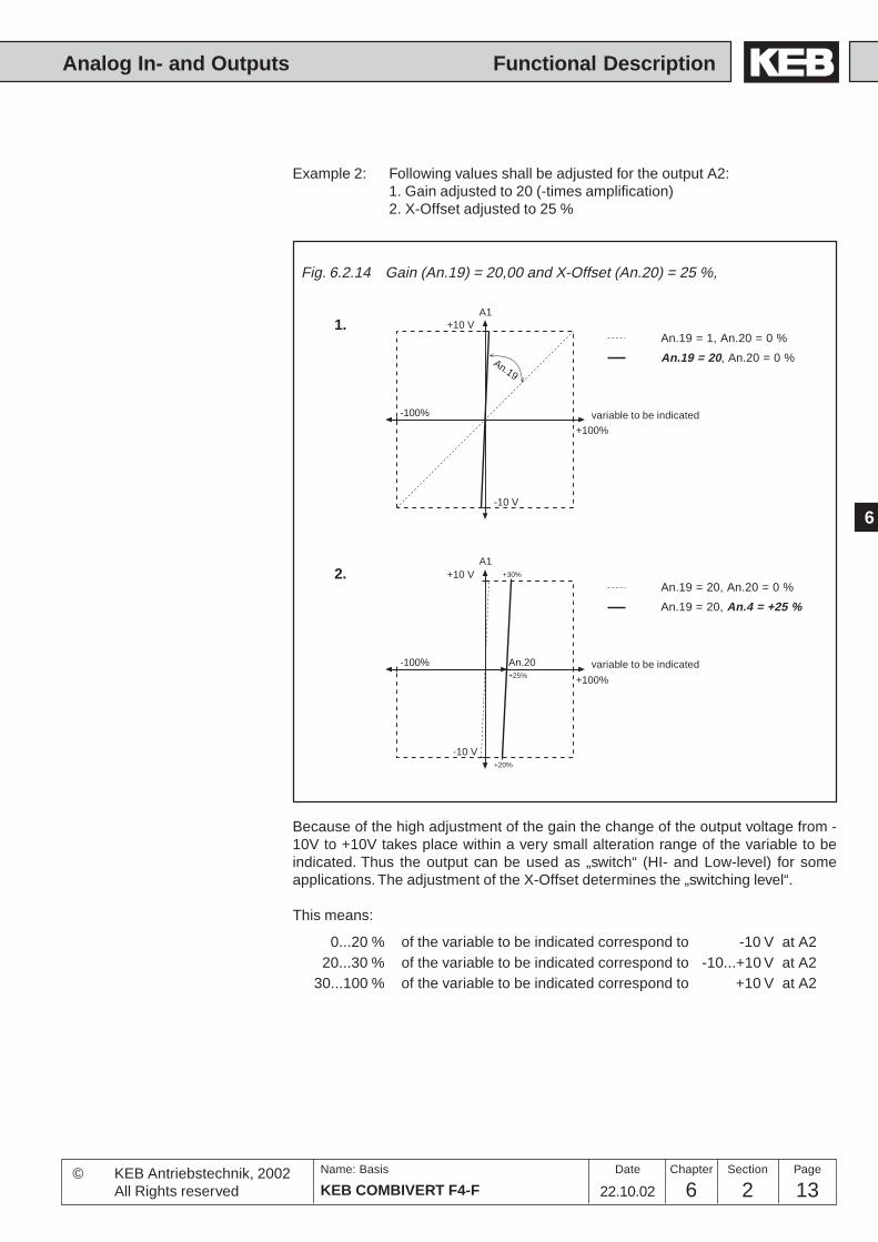
6 2 13KEB COMBIVERT F4-F
Name: Basis
22.10.02
Functional DescriptionAnalog In- and Outputs
Chapter Section PageDate© KEB Antriebstechnik, 2002All Rights reserved
6
+10 V
+100%
-10 V
-100%
An.19
An.19 = 1, An.20 = 0 %
An.19 = 20, An.20 = 0 %
Because of the high adjustment of the gain the change of the output voltage from -10V to +10V takes place within a very small alteration range of the variable to beindicated. Thus the output can be used as „switch“ (HI- and Low-level) for someapplications. The adjustment of the X-Offset determines the „switching level“.
This means:
0...20 % of the variable to be indicated correspond to -10 V at A220...30 % of the variable to be indicated correspond to -10...+10 V at A2
30...100 % of the variable to be indicated correspond to +10 V at A2
Fig. 6.2.14 Gain (An.19) = 20,00 and X-Offset (An.20) = 25 %,
Example 2: Following values shall be adjusted for the output A2:1. Gain adjusted to 20 (-times amplification)2. X-Offset adjusted to 25 %
+10 V
+100%
-10 V
-100% An.20
+20%
+25%
+30%
1.
2.An.19 = 20, An.20 = 0 %
An.19 = 20, An.4 = +25 %
variable to be indicated
variable to be indicated
A1
A1
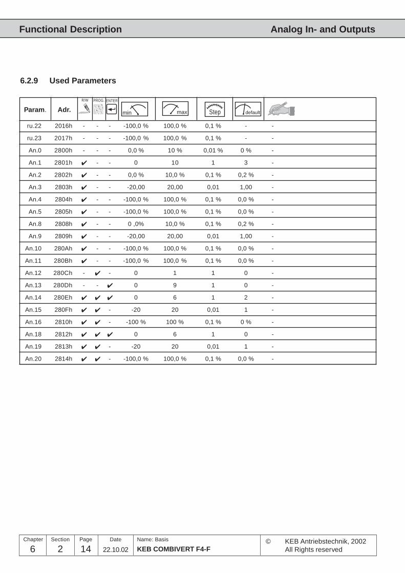
2 146Name: Basis
KEB COMBIVERT F4-F22.10.02
Functional Description Analog In- and Outputs
Chapter Section Page Date © KEB Antriebstechnik, 2002All Rights reserved
StepParam. Adr.ENTERPROG.R/W
min max default
ru.22 2016h - - - -100,0 % 100,0 % 0,1 % - -
ru.23 2017h - - - -100,0 % 100,0 % 0,1 % - -
An.0 2800h - - - 0,0 % 10 % 0,01 % 0 % -
An.1 2801h - - 0 10 1 3 -
An.2 2802h - - 0,0 % 10,0 % 0,1 % 0,2 % -
An.3 2803h - - -20,00 20,00 0,01 1,00 -
An.4 2804h - - -100,0 % 100,0 % 0,1 % 0,0 % -
An.5 2805h - - -100,0 % 100,0 % 0,1 % 0,0 % -
An.8 2808h - - 0 ,0% 10,0 % 0,1 % 0,2 % -
An.9 2809h - - -20,00 20,00 0,01 1,00 -
An.10 280Ah - - -100,0 % 100,0 % 0,1 % 0,0 % -
An.11 280Bh - - -100,0 % 100,0 % 0,1 % 0,0 % -
An.12 280Ch - - 0 1 1 0 -
An.13 280Dh - - 0 9 1 0 -
An.14 280Eh 0 6 1 2 -
An.15 280Fh - -20 20 0,01 1 -
An.16 2810h - -100 % 100 % 0,1 % 0 % -
An.18 2812h 0 6 1 0 -
An.19 2813h - -20 20 0,01 1 -
An.20 2814h - -100,0 % 100,0 % 0,1 % 0,0 % -
6.2.9 Used Parameters
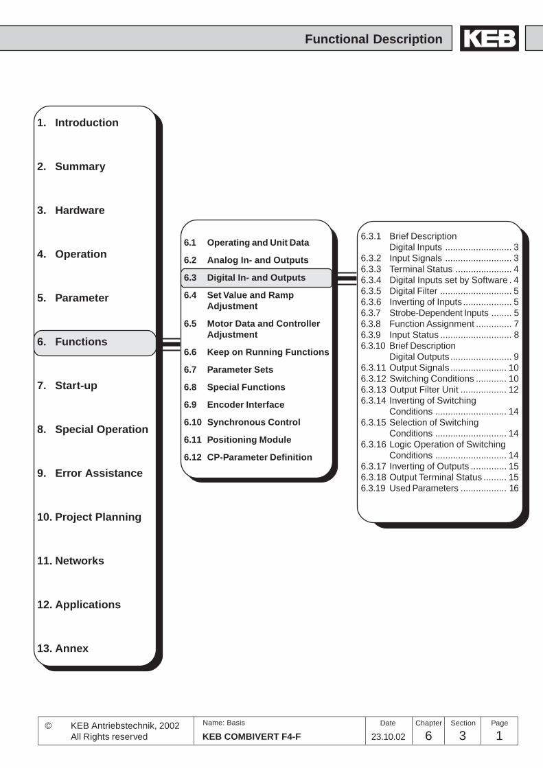
6 3 1KEB COMBIVERT F4-F
Name: Basis
23.10.02
Functional Description
Chapter Section PageDate© KEB Antriebstechnik, 2002All Rights reserved
1. Introduction
2. Summary
3. Hardware
4. Operation
5. Parameter
6. Functions
7. Start-up
8. Special Operation
9. Error Assistance
10. Project Planning
11. Networks
12. Applications
13. Annex
6.1 Operating and Unit Data
6.2 Analog In- and Outputs
6.3 Digital In- and Outputs
6.4 Set Value and RampAdjustment
6.5 Motor Data and ControllerAdjustment
6.6 Keep on Running Functions
6.7 Parameter Sets
6.8 Special Functions
6.9 Encoder Interface
6.10 Synchronous Control
6.11 Positioning Module
6.12 CP-Parameter Definition
6.3.1 Brief DescriptionDigital Inputs .......................... 3
6.3.2 Input Signals .......................... 36.3.3 Terminal Status ...................... 46.3.4 Digital Inputs set by Software . 46.3.5 Digital Filter ............................ 56.3.6 Inverting of Inputs ................... 56.3.7 Strobe-Dependent Inputs ........ 56.3.8 Function Assignment .............. 76.3.9 Input Status ............................ 86.3.10 Brief Description
Digital Outputs ........................ 96.3.11 Output Signals ...................... 106.3.12 Switching Conditions ............ 106.3.13 Output Filter Unit .................. 126.3.14 Inverting of Switching
Conditions ............................ 146.3.15 Selection of Switching
Conditions ............................ 146.3.16 Logic Operation of Switching
Conditions ............................ 146.3.17 Inverting of Outputs .............. 156.3.18 Output Terminal Status ......... 156.3.19 Used Parameters .................. 16

6 3 KEB COMBIVERT F4-F2Name: Basis
23.10.02
Chapter Section Page Date © KEB Antriebstechnik, 2002All Rights reserved
Functional Description Digital In- and Outputs
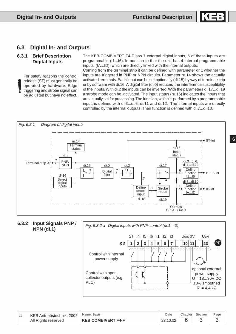
36 3 3KEB COMBIVERT F4-F
Name: Basis
23.10.02
6
Section PageDate© KEB Antriebstechnik, 2002All Rights reserved
Chapter
Functional DescriptionDigital In- and Outputs
2 3 4 5 10 111
I1 I2 I3I4 0VUoutST
PEX2
I5 I6
6 7 23
Uext
+-
6.3.1 Brief DescriptionDigital Inputs
6.3 Digital In- and OutputsThe KEB COMBIVERT F4-F has 7 external digital inputs, 6 of these inputs areprogrammable (I1...I6). In addition to that the unit has 4 internal programmableinputs (IA...ID), which are directly linked with the internal outputs.Coming from the terminal strip it can be defined with parameter dr.1 whether theinputs are triggered in PNP or NPN circuits. Parameter ru.14 shows the actuallyactivated terminals. Each input can be set optionally (di.15) by way of terminal stripor by software with di.16. A digital filter (di.0) reduces the interference susceptibilityof the inputs. With di.2 the inputs can be inverted. With the parameters di.17...di.19a strobe mode can be activated. The input status (ru.16) indicates the inputs thatare actually set for processing. The function, which is performed by a programmableinput, is defined with di.3...di.6, di.11 and di.12. The internal inputs are directlycontrolled by the internal outputs. Their function is defined with di.7...di.10.
Fig. 6.3.1 Diagram of digital inputs
6.3.2 Input Signals PNP /NPN (di.1)
Fig. 6.3.2.a Digital inputs with PNP-control (di.1 = 0)
For safety reasons the controlrelease (ST) must generally beoperated by hardware. Edgetriggering and strobe signal canbe adjusted but have no effect.
7di.1
di.16
di.15
7
di.0 di.217
di.17
di.19di.18
7
1
ru.14
6
4
ru.16
PNP/NPN
Selectdigitalinputs
Digitalfilter
Strobemode
Definestrobeinput
Terminalstatus
Inputstatus
DefinefunctionI1...I6
di.3...di.6,di.11, di.12
DefinefunctionIA...ID
di.7...di.10
OutputsOut A...Out D
I1...I6-int
ID-int
Terminal strip X2
ST-int
Control with open-collector outputs (e.g.PLC)
Control with internalpower supply
optional externalpower supply
U = 18...30V DC±0% smoothed
Ri = 4,4 kΩ
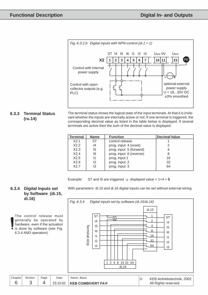
6 3 KEB COMBIVERT F4-F4Name: Basis
23.10.02
Chapter Section Page Date © KEB Antriebstechnik, 2002All Rights reserved
Functional Description Digital In- and Outputs
1 2 4 8 16 32 64
ST
I4
I5
I6
I1
I2
I3
ST
I4
I5
I6
I1
I2
I3
di.16
1
2
4
8
16
32
64
di.15
&
2 3 4 5 10 111
I1 I2 I3I4 0VUoutST
PEX2
I5 I6
6 7 23
Uext
+-
Fig. 6.3.2.b Digital inputs with NPN-control (di.1 = 1)
Terminal Name Function Decimal ValueX2.1 ST control release 1X2.2 I4 prog. input 4 (reset) 2X2.3 I5 prog. input 5 (forward) 4X2.4 I6 prog. input 6 (reverse) 8X2.5 I1 prog. input 1 16X2.6 I2 prog. input 2 32X2.7 I3 prog. input 3 64
6.3.3 Terminal Status(ru.14)
The terminal status shows the logical state of the input terminals. At that it is irrele-vant whether the inputs are internally active or not. If one terminal is triggered, thecorresponding decimal value as listed in the table below is displayed. If severalterminals are active then the sum of the decimal value is displayed.
6.3.4 Digital Inputs setby Software (di.15,di.16)
With parameters di.15 and di.16 digital inputs can be set without external wiring.
Example: ST and I5 are triggered displayed value = 1+4 = 5
Terminal strip
Fig. 6.3.4 Digital inputs set by software (di.15/di.16)
The control release mustgenerally be operated byhardware, even if the actuationis done by software (see Fig.6.3.4 AND operation).
Control with open-collector outputs (e.g.PLC)
Control with internalpower supply
optional externalpower supply
U = 18...30V DC±0% smoothed
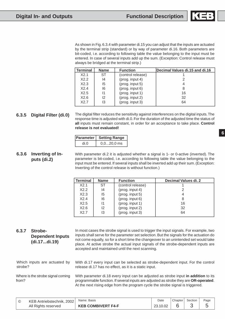
56 3 5KEB COMBIVERT F4-F
Name: Basis
23.10.02
6
Section PageDate© KEB Antriebstechnik, 2002All Rights reserved
Chapter
Functional DescriptionDigital In- and Outputs
The digital filter reduces the sensitivity against interferences on the digital inputs. Theresponse time is adjusted with di.0. For the duration of the adjusted time the status ofall inputs must remain constant, in order for an acceptance to take place. Controlrelease is not evaluated!
Parameter Setting Range
di.0 0,0...20,0 ms
As shown in Fig. 6.3.4 with parameter di.15 you can adjust that the inputs are actuatedby the terminal strip (standard) or by way of parameter di.16. Both parameters arebit-coded, i.e. according to following table the value belonging to the input must beentered. In case of several inputs add up the sum. (Exception: Control release mustalways be bridged at the terminal strip.)
Terminal Name Function Decimal Values di.15 and di.16X2.1 ST (control release) 1X2.2 I4 (prog. input 4) 2X2.3 I5 (prog. input 5) 4X2.4 I6 (prog. input 6) 8X2.5 I1 (prog. input 1) 16X2.6 I2 (prog. input 2) 32X2.7 I3 (prog. input 3) 64
6.3.5 Digital Filter (di.0)
6.3.6 Inverting of In-puts (di.2)
With parameter di.2 it is adjusted whether a signal is 1- or 0-active (inverted). Theparameter is bit-coded, i.e. according to following table the value belonging to theinput must be entered. If several inputs shall be inverted add up their sum. (Exception:Inverting of the control release is without function.)
Terminal Name Function Decimal Values di. 2X2.1 ST (control release) 1X2.2 I4 (prog. input 4) 2X2.3 I5 (prog. input 5) 4X2.4 I6 (prog. input 6) 8X2.5 I1 (prog. input 1) 16X2.6 I2 (prog. input 2) 32X2.7 I3 (prog. input 3) 64
6.3.7 Strobe-Dependent Inputs(di.17...di.19)
In most cases the strobe signal is used to trigger the input signals. For example, twoinputs shall serve for the parameter set selection. But the signals for the actuation donot come equally, so for a short time the changeover to an unintended set would takeplace. At active strobe the actual input signals of the strobe-dependent inputs areaccepted and maintained until the next scanning.
With di.17 every input can be selected as strobe-dependent input. For the controlrelease di.17 has no effect, as it is a static input.
With parameter di.18 every input can be adjusted as strobe input in addition to itsprogrammable function. If several inputs are adjusted as strobe they are OR-operated.At the next rising edge from the program cycle the strobe signal is triggered.
Where is the strobe signal comingfrom?
Which inputs are actuated bystrobe?
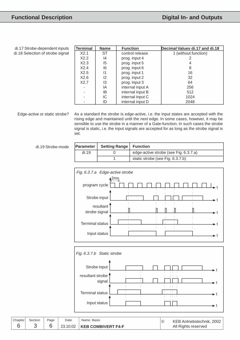
6 3 KEB COMBIVERT F4-F6Name: Basis
23.10.02
Chapter Section Page Date © KEB Antriebstechnik, 2002All Rights reserved
Functional Description Digital In- and Outputs
Terminal Name Function Decimal Values di.17 and di.18X2.1 ST control release 1 (without function)X2.2 I4 prog. input 4 2X2.3 I5 prog. input 5 4X2.4 I6 prog. input 6 8X2.5 I1 prog. input 1 16X2.6 I2 prog. input 2 32X2.7 I3 prog. input 3 64
- IA internal input A 256- IB internal input B 512- IC internal input C 1024- ID internal input D 2048
t
t
t
t
t
2ms
t
t
t
t
di.17 Strobe-dependent inputsdi.18 Selection of strobe signal
Edge-active or static strobe? As a standard the strobe is edge-active, i.e. the input states are accepted with therising edge and maintained until the next edge. In some cases, however, it may besensible to use the strobe in a manner of a Gate-function. In such cases the strobesignal is static, i.e. the input signals are accepted for as long as the strobe signal isset.
di.19 Strobe-mode
Fig. 6.3.7.a Edge-active strobe
Fig. 6.3.7.b Static strobe
Strobe input
resultant strobesignal
Terminal status
Input status
program cycle
Strobe input
resultantstrobe signal
Terminal status
Input status
Parameter Setting Range Function
di.19 0 edge-active strobe (see Fig. 6.3.7.a)
1 static strobe (see Fig. 6.3.7.b)
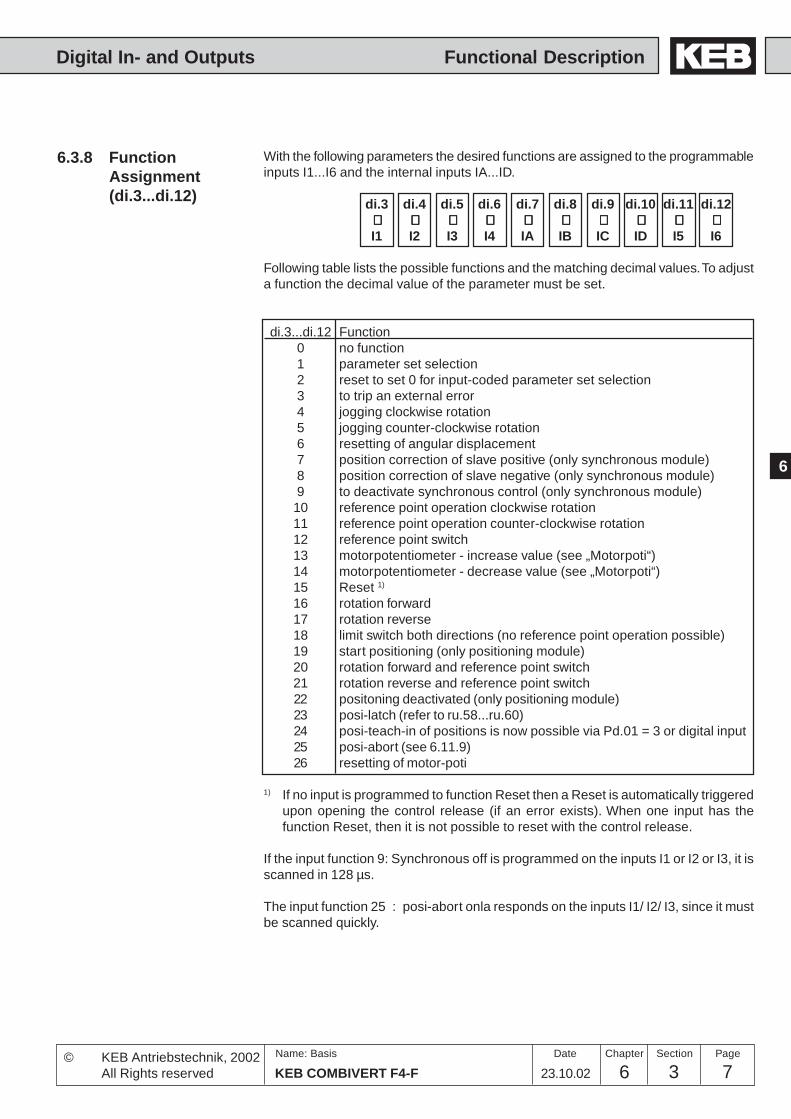
76 3 7KEB COMBIVERT F4-F
Name: Basis
23.10.02
6
Section PageDate© KEB Antriebstechnik, 2002All Rights reserved
Chapter
Functional DescriptionDigital In- and Outputs
di.3...di.12 Function0 no function1 parameter set selection2 reset to set 0 for input-coded parameter set selection3 to trip an external error4 jogging clockwise rotation5 jogging counter-clockwise rotation6 resetting of angular displacement7 position correction of slave positive (only synchronous module)8 position correction of slave negative (only synchronous module)9 to deactivate synchronous control (only synchronous module)10 reference point operation clockwise rotation11 reference point operation counter-clockwise rotation12 reference point switch13 motorpotentiometer - increase value (see „Motorpoti“)14 motorpotentiometer - decrease value (see „Motorpoti“)15 Reset 1)
16 rotation forward17 rotation reverse18 limit switch both directions (no reference point operation possible)19 start positioning (only positioning module)20 rotation forward and reference point switch21 rotation reverse and reference point switch22 positoning deactivated (only positioning module)23 posi-latch (refer to ru.58...ru.60)24 posi-teach-in of positions is now possible via Pd.01 = 3 or digital input25 posi-abort (see 6.11.9)26 resetting of motor-poti
1) If no input is programmed to function Reset then a Reset is automatically triggeredupon opening the control release (if an error exists). When one input has thefunction Reset, then it is not possible to reset with the control release.
If the input function 9: Synchronous off is programmed on the inputs I1 or I2 or I3, it isscanned in 128 µs.
The input function 25 : posi-abort onla responds on the inputs I1/ I2/ I3, since it mustbe scanned quickly.
6.3.8 FunctionAssignment(di.3...di.12)
With the following parameters the desired functions are assigned to the programmableinputs I1...I6 and the internal inputs IA...ID.
di.3 di.4 di.5 di.6 di.7 di.8 di.9 di.10 di.11 di.12⇓⇓⇓⇓⇓ ⇓⇓⇓⇓⇓ ⇓⇓⇓⇓⇓ ⇓⇓⇓⇓⇓ ⇓⇓⇓⇓⇓ ⇓⇓⇓⇓⇓ ⇓⇓⇓⇓⇓ ⇓⇓⇓⇓⇓ ⇓⇓⇓⇓⇓ ⇓⇓⇓⇓⇓I1 I2 I3 I4 IA IB IC ID I5 I6
Following table lists the possible functions and the matching decimal values. To adjusta function the decimal value of the parameter must be set.
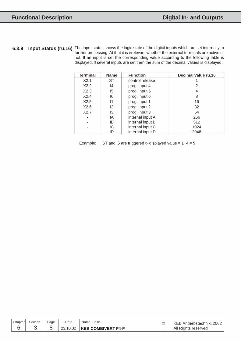
6 3 KEB COMBIVERT F4-F8Name: Basis
23.10.02
Chapter Section Page Date © KEB Antriebstechnik, 2002All Rights reserved
Functional Description Digital In- and Outputs
Terminal Name Function Decimal Value ru.16X2.1 ST control release 1X2.2 I4 prog. input 4 2X2.3 I5 prog. input 5 4X2.4 I6 prog. input 6 8X2.5 I1 prog. input 1 16X2.6 I2 prog. input 2 32X2.7 I3 prog. input 3 64
- IA internal input A 256- IB internal input B 512- IC internal input C 1024- ID internal input D 2048
6.3.9 Input Status (ru.16) The input status shows the logic state of the digital inputs which are set internally tofurther processing. At that it is irrelevant whether the external terminals are active ornot. If an input is set the corresponding value according to the following table isdisplayed. If several inputs are set then the sum of the decimal values is displayed.
Example: ST and I5 are triggered displayed value = 1+4 = 5
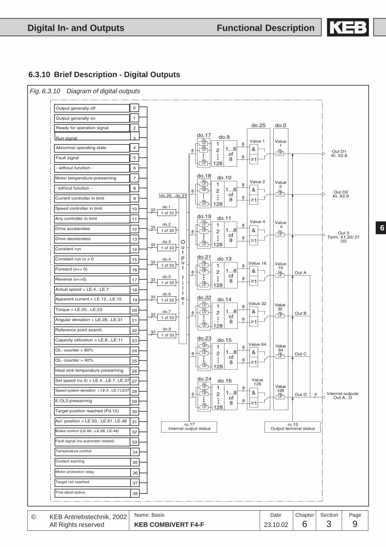
96 3 9KEB COMBIVERT F4-F
Name: Basis
23.10.02
6
Section PageDate© KEB Antriebstechnik, 2002All Rights reserved
Chapter
Functional DescriptionDigital In- and Outputs
Fig. 6.3.10 Diagram of digital outputs
!
"#!$
"#!$
#%&'('''%&')
* +#%&',!'''%&',-
#%&',.'''%&'-/
0 #%&'.'''%&'//
% #.!1
% #(!1
23
'($#%&'('''%&')4%&'-)
#%&'('''%&')4%&-)
&'%,
* 5'/,$
' #%&'6!'''%&'7/4%&'(.
83 %&'77'''%&'7.4%&'(.$
$
!
/
,
-
/!
//
/,
/-
/(
/6
/7
/)
/.
,!
,/
,,
,-
,(
,6
,7
,)
,.
,9
-!
-/
-,
--
9
.
)
7
6
(
#%&'/,'''%&'/6 /9
:
#/
;/
/ /<'=,'.
:
#/
/ ,<'=,'9
:
#/
/ -*'=/',!>,/
>,,
:
#/
/
:
#/
/ 8
:
#/
/
:
#/
/
',6 '!
;,
;(
;/7
;-,
;7(
;/,.
;/
;,
;(
;/7
;-,
;7(
;/,.
'/6
? '''
(
'/)?
//
/
'/)
/,
/,.
/'''. .
'9
.
.
.
//
/
'/.
/,
/,.
/'''. .
'/!
.
.
.
//
/
'/9
/,
/,.
/'''. .
'//
.
.
.
//
/
',/
/,
/,.
/'''. .
'/-
.
.
.
//
/
',,
/,
/,.
/'''. .
'/(
.
.
.
//
/
',-
/,
/,.
/'''. .
'/6
.
.
.
//
/
',(
/,
/,.
/'''. .
'/7
.
.
.
/ --
'/--
/ --
',--
/ --
'---
/ --
'(--
/ --
'6--
/ --
'7--
/ --
')--
/ --
'.--
',7''' '-/
*
-(
-6
*
-7
-)
5 -.
6.3.10 Brief Description - Digital Outputs
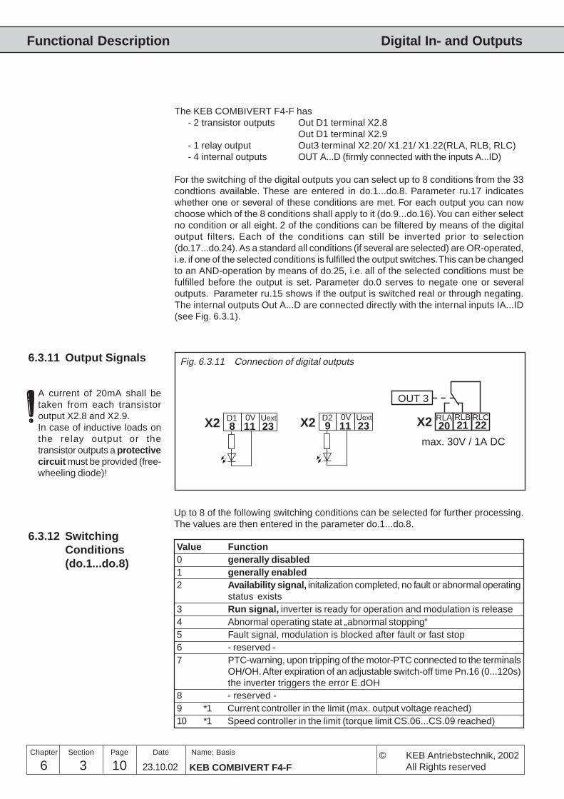
6 3 KEB COMBIVERT F4-F10Name: Basis
23.10.02
Chapter Section Page Date © KEB Antriebstechnik, 2002All Rights reserved
Functional Description Digital In- and Outputs
OUT 3
8 11 23D1 0V UextX2 9 11 23
D2 0V UextX2 20 21 22RLA RLB RLCX2
max. 30V / 1A DC
The KEB COMBIVERT F4-F has- 2 transistor outputs Out D1 terminal X2.8
Out D1 terminal X2.9- 1 relay output Out3 terminal X2.20/ X1.21/ X1.22(RLA, RLB, RLC)- 4 internal outputs OUT A...D (firmly connected with the inputs A...ID)
For the switching of the digital outputs you can select up to 8 conditions from the 33condtions available. These are entered in do.1...do.8. Parameter ru.17 indicateswhether one or several of these conditions are met. For each output you can nowchoose which of the 8 conditions shall apply to it (do.9...do.16). You can either selectno condition or all eight. 2 of the conditions can be filtered by means of the digitaloutput filters. Each of the conditions can still be inverted prior to selection(do.17...do.24). As a standard all conditions (if several are selected) are OR-operated,i.e. if one of the selected conditions is fulfilled the output switches. This can be changedto an AND-operation by means of do.25, i.e. all of the selected conditions must befulfilled before the output is set. Parameter do.0 serves to negate one or severaloutputs. Parameter ru.15 shows if the output is switched real or through negating.The internal outputs Out A...D are connected directly with the internal inputs IA...ID(see Fig. 6.3.1).
6.3.11 Output Signals Fig. 6.3.11 Connection of digital outputs
6.3.12 SwitchingConditions(do.1...do.8)
Up to 8 of the following switching conditions can be selected for further processing.The values are then entered in the parameter do.1...do.8.
Value Function0 generally disabled1 generally enabled2 Availability signal, initalization completed, no fault or abnormal operating
status exists3 Run signal, inverter is ready for operation and modulation is release4 Abnormal operating state at „abnormal stopping“5 Fault signal, modulation is blocked after fault or fast stop6 - reserved -7 PTC-warning, upon tripping of the motor-PTC connected to the terminals
OH/OH. After expiration of an adjustable switch-off time Pn.16 (0...120s)the inverter triggers the error E.dOH
8 - reserved -9 *1 Current controller in the limit (max. output voltage reached)10 *1 Speed controller in the limit (torque limit CS.06...CS.09 reached)
A current of 20mA shall betaken from each transistoroutput X2.8 and X2.9.In case of inductive loads onthe relay output or thetransistor outputs a protectivecircuit must be provided (free-wheeling diode)!
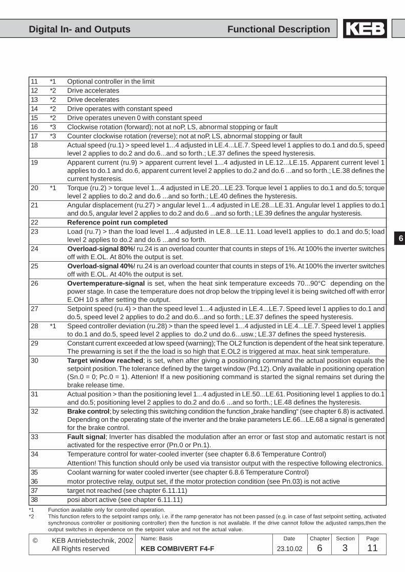
116 3 11KEB COMBIVERT F4-F
Name: Basis
23.10.02
6
Section PageDate© KEB Antriebstechnik, 2002All Rights reserved
Chapter
Functional DescriptionDigital In- and Outputs
11 *1 Optional controller in the limit12 *2 Drive accelerates13 *2 Drive decelerates14 *2 Drive operates with constant speed15 *2 Drive operates uneven 0 with constant speed16 *3 Clockwise rotation (forward); not at noP, LS, abnormal stopping or fault17 *3 Counter clockwise rotation (reverse); not at noP, LS, abnormal stopping or fault18 Actual speed (ru.1) > speed level 1...4 adjusted in LE.4...LE.7. Speed level 1 applies to do.1 and do.5, speed
level 2 applies to do.2 and do.6...and so forth.; LE.37 defines the speed hysteresis.19 Apparent current (ru.9) > apparent current level 1...4 adjusted in LE.12...LE.15. Apparent current level 1
applies to do.1 and do.6, apparent current level 2 applies to do.2 and do.6 ...and so forth.; LE.38 defines thecurrent hysteresis.
20 *1 Torque (ru.2) > torque level 1...4 adjusted in LE.20...LE.23. Torque level 1 applies to do.1 and do.5; torquelevel 2 applies to do.2 and do.6 ...and so forth.; LE.40 defines the hysteresis.
21 Angular displacement (ru.27) > angular level 1...4 adjusted in LE.28...LE.31. Angular level 1 applies to do.1and do.5, angular level 2 applies to do.2 and do.6 ...and so forth.; LE.39 defines the angular hysteresis.
22 Reference point run completed23 Load (ru.7) > than the load level 1...4 adjusted in LE.8...LE.11. Load level1 applies to do.1 and do.5; load
level 2 applies to do.2 and do.6 ...and so forth.24 Overload-signal 80%! ru.24 is an overload counter that counts in steps of 1%. At 100% the inverter switches
off with E.OL. At 80% the output is set.25 Overload-signal 40%! ru.24 is an overload counter that counts in steps of 1%. At 100% the inverter switches
off with E.OL. At 40% the output is set.26 Overtemperature-signal is set, when the heat sink temperature exceeds 70...90°C depending on the
power stage. In case the temperature does not drop below the tripping level it is being switched off with errorE.OH 10 s after setting the output.
27 Setpoint speed (ru.4) > than the speed level 1...4 adjusted in LE.4...LE.7. Speed level 1 applies to do.1 anddo.5, speed level 2 applies to do.2 and do.6...and so forth.; LE.37 defines the speed hysteresis.
28 *1 Speed controller deviation (ru.28) > than the speed level 1...4 adjusted in LE.4...LE.7. Speed level 1 appliesto do.1 and do.5, speed level 2 applies to do.2 und do.6...usw.; LE.37 defines the speed hysteresis.
29 Constant current exceeded at low speed (warning); The OL2 function is dependent of the heat sink teperature.The prewarning is set if the the load is so high that E.OL2 is triggered at max. heat sink temperature.
30 Target window reached; is set, when after giving a positioning command the actual position equals thesetpoint position. The tolerance defined by the target window (Pd.12). Only available in positioning operation(Sn.0 = 0; Pc.0 = 1). Attenion! If a new positioning command is started the signal remains set during thebrake release time.
31 Actual position > than the positioning level 1...4 adjusted in LE.50...LE.61. Positioning level 1 applies to do.1and do.5; positioning level 2 applies to do.2 and do.6 ...and so forth.; LE.48 defines the hysteresis.
32 Brake control; by selecting this switching condition the function „brake handling“ (see chapter 6.8) is activated.Depending on the operating state of the inverter and the brake parameters LE.66...LE.68 a signal is generatedfor the brake control.
33 Fault signal; Inverter has disabled the modulation after an error or fast stop and automatic restart is notactivated for the respective error (Pn.0 or Pn.1).
34 Temperature control for water-cooled inverter (see chapter 6.8.6 Temperature Control)Attention! This function should only be used via transistor output with the respective following electronics.
35 Coolant warning for water cooled inverter (see chapter 6.8.6 Temperature Control)36 motor protective relay, output set, if the motor protection condition (see Pn.03) is not active37 target not reached (see chapter 6.11.11)38 posi abort active (see chapter 6.11.11)
*1 Function available only for controlled operation.*2 This function refers to the setpoint ramps only, i.e. if the ramp generator has not been passed (e.g. in case of fast setpoint setting, activated
synchronous controller or positioning controller) then the function is not available. If the drive cannot follow the adjusted ramps,then theoutput switches in dependence on the setpoint value and not the actual value.
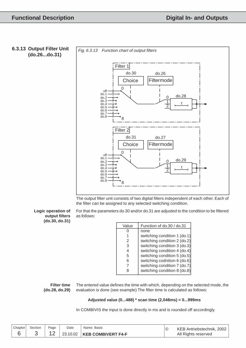
6 3 KEB COMBIVERT F4-F12Name: Basis
23.10.02
Chapter Section Page Date © KEB Antriebstechnik, 2002All Rights reserved
Functional Description Digital In- and Outputs
6.3.13 Output Filter Unit(do.26...do.31)
t
do.28
do.26do.30
do.1do.2do.3do.4do.5do.6do.7do.8
off
012
0
8
t
do.29
do.27do.31
do.1do.2do.3do.4do.5do.6do.7do.8
off
012
0
8
Fig. 6.3.13 Function chart of output filters
The output filter unit consists of two digital filters independent of each other. Each ofthe filter can be assigned to any selected switching condition.
Logic operation ofoutput filters
(do.30, do.31)
For that the parameters do.30 and/or do.31 are adjusted to the condition to be filteredas follows:
Value Function of do.30 / do.310 none1 switching condition 1 (do.1)2 switching condition 2 (do.2)3 switching condition 3 (do.3)4 switching condition 4 (do.4)5 switching condition 5 (do.5)6 switching codnition 6 (do.6)7 switching condition 7 (do.7)8 switching condition 8 (do.8)
Filter time(do.28, do.29)
The entered value defines the time with which, depending on the selected mode, theevaluation is done (see example) The filter time is calculated as follows:
Adjusted value (0...488) * scan time (2,048ms) = 0...999ms
In COMBIVIS the input is done directly in ms and is rounded off accordingly.
Filter 1
Choice Filtermode
Filter 2
Choice Filtermode
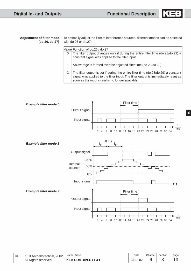
136 3 13KEB COMBIVERT F4-F
Name: Basis
23.10.02
6
Section PageDate© KEB Antriebstechnik, 2002All Rights reserved
Chapter
Functional DescriptionDigital In- and Outputs
0%
50%
100%
tF tF
t
2 4 6 8 10 12 14 16 18 20 22 24 26 28 30 32 34
tms
2 4 6 8 10 12 14 16 18 20 22 24 26 28 30 32 34
tms
Adjustment of filter mode(do.26, do.27)
To optimally adjust the filter to interference sources, different modes can be selectedwith do.26 or do.27:
Value Function of do.26 / do.270 The filter output changes only if during the entire filter time (do.28/do.29) a
constant signal was applied to the filter input.
1 An average is formed over the adjusted filter time (do.28/do.29)
2 The filter output is set if during the entire filter time (do.28/do.29) a constantsignal was applied to the filter input. The filter output is immediately reset assoon as the input signal is no longer available.
Example filter mode 0
Output signal
Filter time
Filter time
8 ms
Output signal
Output signal
Input signal
Input signal
Input signal
Internalcounter
Example filter mode 1
Example filter mode 2
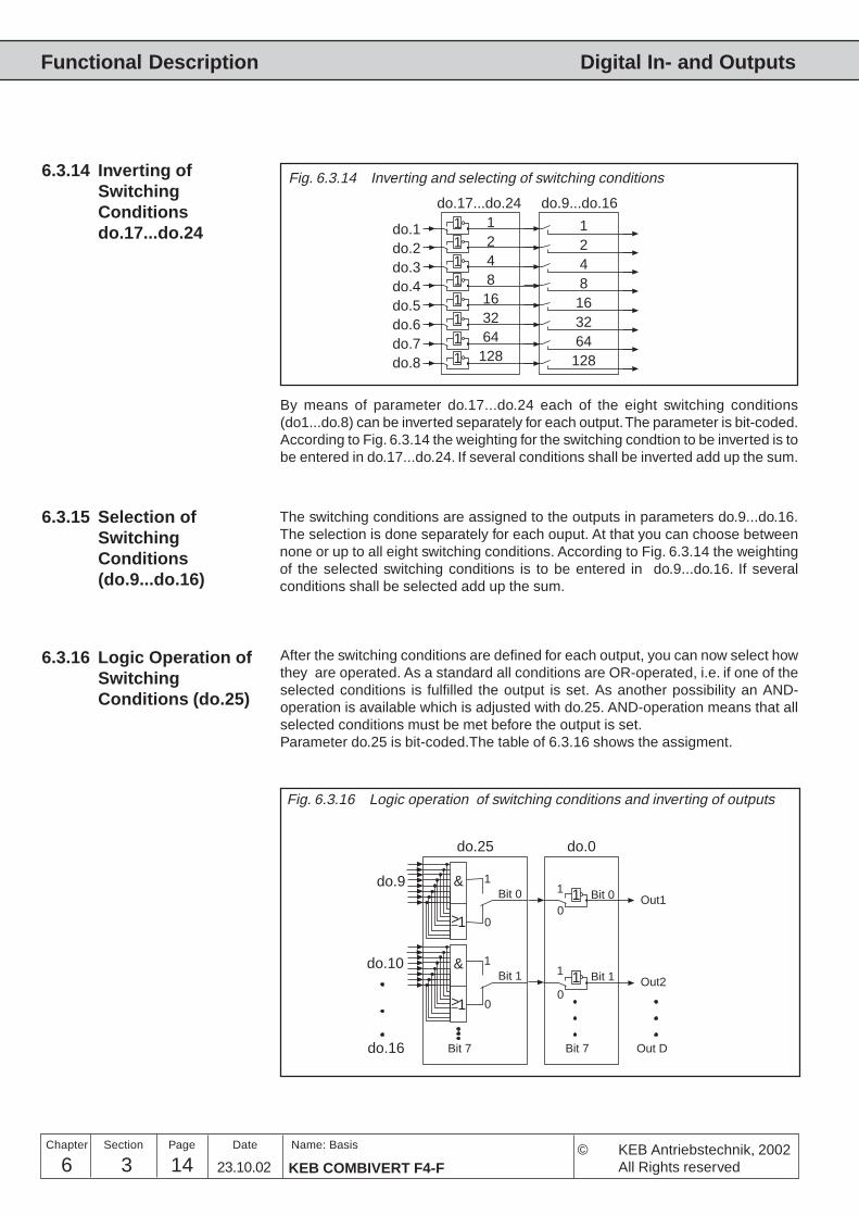
6 3 KEB COMBIVERT F4-F14Name: Basis
23.10.02
Chapter Section Page Date © KEB Antriebstechnik, 2002All Rights reserved
Functional Description Digital In- and Outputs
0
1Bit 0
0
1Bit 1
Bit 7
1 Out1
Out21
Bit 7
Bit 0
Bit 1
0
1
0
1
Out D
&
>1
&
>1
do.25 do.0
do.10
do.9
do.16
11111
111
do.17...do.24
do.1do.2do.3do.4do.5do.6do.7do.8
1248
163264
128
do.9...do.16
1248
163264
128
Fig. 6.3.14 Inverting and selecting of switching conditions6.3.14 Inverting ofSwitchingConditionsdo.17...do.24
By means of parameter do.17...do.24 each of the eight switching conditions(do1...do.8) can be inverted separately for each output. The parameter is bit-coded.According to Fig. 6.3.14 the weighting for the switching condtion to be inverted is tobe entered in do.17...do.24. If several conditions shall be inverted add up the sum.
6.3.15 Selection ofSwitchingConditions(do.9...do.16)
After the switching conditions are defined for each output, you can now select howthey are operated. As a standard all conditions are OR-operated, i.e. if one of theselected conditions is fulfilled the output is set. As another possibility an AND-operation is available which is adjusted with do.25. AND-operation means that allselected conditions must be met before the output is set.Parameter do.25 is bit-coded.The table of 6.3.16 shows the assigment.
6.3.16 Logic Operation ofSwitchingConditions (do.25)
Fig. 6.3.16 Logic operation of switching conditions and inverting of outputs
The switching conditions are assigned to the outputs in parameters do.9...do.16.The selection is done separately for each ouput. At that you can choose betweennone or up to all eight switching conditions. According to Fig. 6.3.14 the weightingof the selected switching conditions is to be entered in do.9...do.16. If severalconditions shall be selected add up the sum.
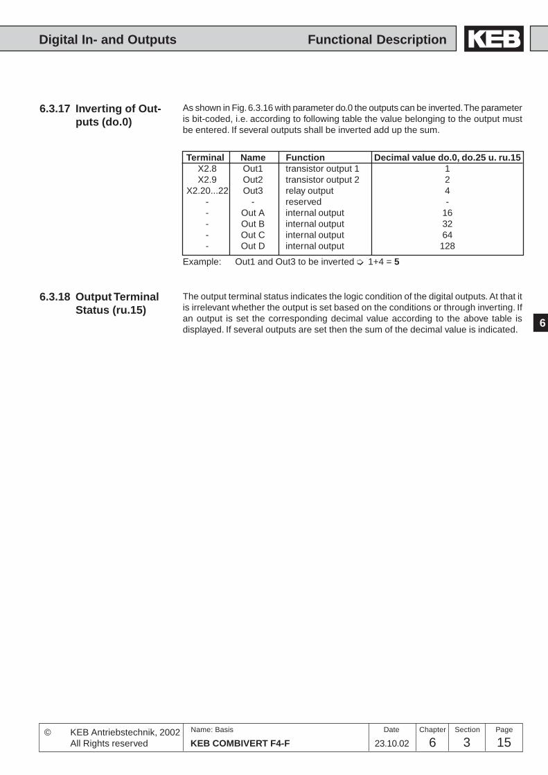
156 3 15KEB COMBIVERT F4-F
Name: Basis
23.10.02
6
Section PageDate© KEB Antriebstechnik, 2002All Rights reserved
Chapter
Functional DescriptionDigital In- and Outputs
Terminal Name Function Decimal value do.0, do.25 u. ru.15X2.8 Out1 transistor output 1 1X2.9 Out2 transistor output 2 2
X2.20...22 Out3 relay output 4- - reserved -- Out A internal output 16- Out B internal output 32- Out C internal output 64- Out D internal output 128
6.3.17 Inverting of Out-puts (do.0)
As shown in Fig. 6.3.16 with parameter do.0 the outputs can be inverted. The parameteris bit-coded, i.e. according to following table the value belonging to the output mustbe entered. If several outputs shall be inverted add up the sum.
6.3.18 Output TerminalStatus (ru.15)
The output terminal status indicates the logic condition of the digital outputs. At that itis irrelevant whether the output is set based on the conditions or through inverting. Ifan output is set the corresponding decimal value according to the above table isdisplayed. If several outputs are set then the sum of the decimal value is indicated.
Example: Out1 and Out3 to be inverted 1+4 = 5
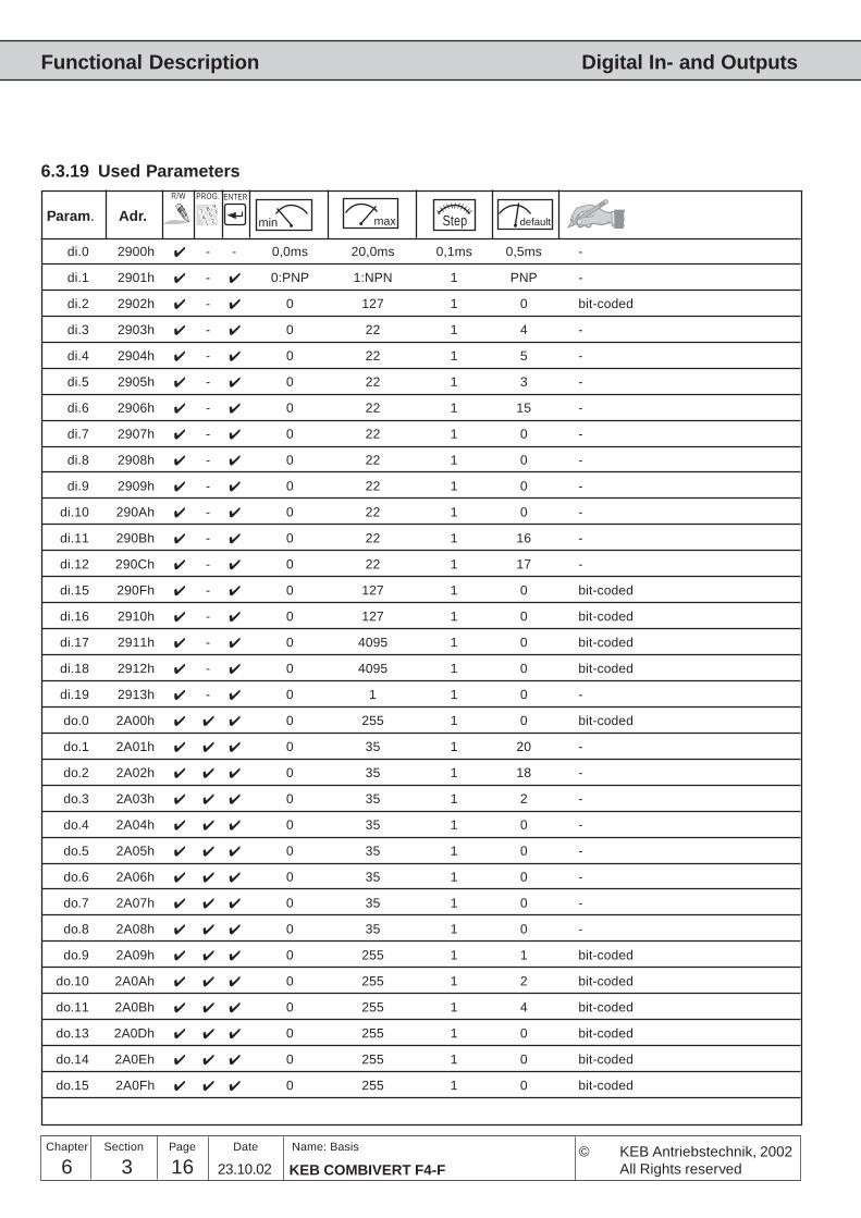
6 3 KEB COMBIVERT F4-F16Name: Basis
23.10.02
Chapter Section Page Date © KEB Antriebstechnik, 2002All Rights reserved
Functional Description Digital In- and Outputs
Param. Adr. min max default
ENTERPROG.R/W
Step
di.0 2900h - - 0,0ms 20,0ms 0,1ms 0,5ms -
di.1 2901h - 0:PNP 1:NPN 1 PNP -
di.2 2902h - 0 127 1 0 bit-coded
di.3 2903h - 0 22 1 4 -
di.4 2904h - 0 22 1 5 -
di.5 2905h - 0 22 1 3 -
di.6 2906h - 0 22 1 15 -
di.7 2907h - 0 22 1 0 -
di.8 2908h - 0 22 1 0 -
di.9 2909h - 0 22 1 0 -
di.10 290Ah - 0 22 1 0 -
di.11 290Bh - 0 22 1 16 -
di.12 290Ch - 0 22 1 17 -
di.15 290Fh - 0 127 1 0 bit-coded
di.16 2910h - 0 127 1 0 bit-coded
di.17 2911h - 0 4095 1 0 bit-coded
di.18 2912h - 0 4095 1 0 bit-coded
di.19 2913h - 0 1 1 0 -
do.0 2A00h 0 255 1 0 bit-coded
do.1 2A01h 0 35 1 20 -
do.2 2A02h 0 35 1 18 -
do.3 2A03h 0 35 1 2 -
do.4 2A04h 0 35 1 0 -
do.5 2A05h 0 35 1 0 -
do.6 2A06h 0 35 1 0 -
do.7 2A07h 0 35 1 0 -
do.8 2A08h 0 35 1 0 -
do.9 2A09h 0 255 1 1 bit-coded
do.10 2A0Ah 0 255 1 2 bit-coded
do.11 2A0Bh 0 255 1 4 bit-coded
do.13 2A0Dh 0 255 1 0 bit-coded
do.14 2A0Eh 0 255 1 0 bit-coded
do.15 2A0Fh 0 255 1 0 bit-coded
6.3.19 Used Parameters
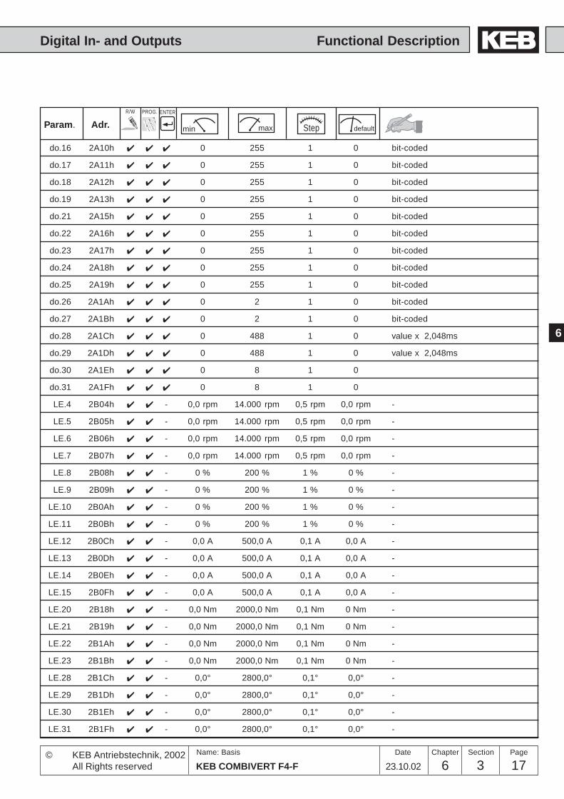
176 3 17KEB COMBIVERT F4-F
Name: Basis
23.10.02
6
Section PageDate© KEB Antriebstechnik, 2002All Rights reserved
Chapter
Functional DescriptionDigital In- and Outputs
Param. Adr. min max default
ENTERPROG.R/W
Step
do.16 2A10h 0 255 1 0 bit-coded
do.17 2A11h 0 255 1 0 bit-coded
do.18 2A12h 0 255 1 0 bit-coded
do.19 2A13h 0 255 1 0 bit-coded
do.21 2A15h 0 255 1 0 bit-coded
do.22 2A16h 0 255 1 0 bit-coded
do.23 2A17h 0 255 1 0 bit-coded
do.24 2A18h 0 255 1 0 bit-coded
do.25 2A19h 0 255 1 0 bit-coded
do.26 2A1Ah 0 2 1 0 bit-coded
do.27 2A1Bh 0 2 1 0 bit-coded
do.28 2A1Ch 0 488 1 0 value x 2,048ms
do.29 2A1Dh 0 488 1 0 value x 2,048ms
do.30 2A1Eh 0 8 1 0
do.31 2A1Fh 0 8 1 0
LE.4 2B04h - 0,0 rpm 14.000 rpm 0,5 rpm 0,0 rpm -
LE.5 2B05h - 0,0 rpm 14.000 rpm 0,5 rpm 0,0 rpm -
LE.6 2B06h - 0,0 rpm 14.000 rpm 0,5 rpm 0,0 rpm -
LE.7 2B07h - 0,0 rpm 14.000 rpm 0,5 rpm 0,0 rpm -
LE.8 2B08h - 0 % 200 % 1 % 0 % -
LE.9 2B09h - 0 % 200 % 1 % 0 % -
LE.10 2B0Ah - 0 % 200 % 1 % 0 % -
LE.11 2B0Bh - 0 % 200 % 1 % 0 % -
LE.12 2B0Ch - 0,0 A 500,0 A 0,1 A 0,0 A -
LE.13 2B0Dh - 0,0 A 500,0 A 0,1 A 0,0 A -
LE.14 2B0Eh - 0,0 A 500,0 A 0,1 A 0,0 A -
LE.15 2B0Fh - 0,0 A 500,0 A 0,1 A 0,0 A -
LE.20 2B18h - 0,0 Nm 2000,0 Nm 0,1 Nm 0 Nm -
LE.21 2B19h - 0,0 Nm 2000,0 Nm 0,1 Nm 0 Nm -
LE.22 2B1Ah - 0,0 Nm 2000,0 Nm 0,1 Nm 0 Nm -
LE.23 2B1Bh - 0,0 Nm 2000,0 Nm 0,1 Nm 0 Nm -
LE.28 2B1Ch - 0,0° 2800,0° 0,1° 0,0° -
LE.29 2B1Dh - 0,0° 2800,0° 0,1° 0,0° -
LE.30 2B1Eh - 0,0° 2800,0° 0,1° 0,0° -
LE.31 2B1Fh - 0,0° 2800,0° 0,1° 0,0° -
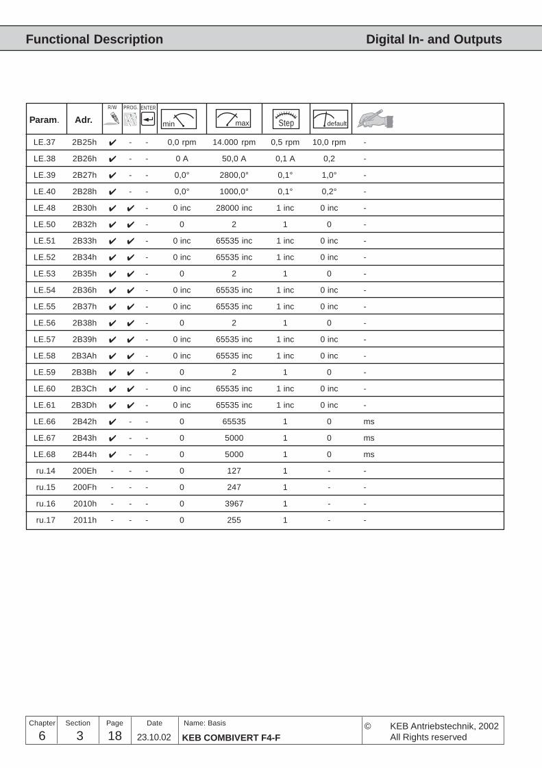
6 3 KEB COMBIVERT F4-F18Name: Basis
23.10.02
Chapter Section Page Date © KEB Antriebstechnik, 2002All Rights reserved
Functional Description Digital In- and Outputs
Param. Adr. min max default
ENTERPROG.R/W
Step
LE.37 2B25h - - 0,0 rpm 14.000 rpm 0,5 rpm 10,0 rpm -
LE.38 2B26h - - 0 A 50,0 A 0,1 A 0,2 -
LE.39 2B27h - - 0,0° 2800,0° 0,1° 1,0° -
LE.40 2B28h - - 0,0° 1000,0° 0,1° 0,2° -
LE.48 2B30h - 0 inc 28000 inc 1 inc 0 inc -
LE.50 2B32h - 0 2 1 0 -
LE.51 2B33h - 0 inc 65535 inc 1 inc 0 inc -
LE.52 2B34h - 0 inc 65535 inc 1 inc 0 inc -
LE.53 2B35h - 0 2 1 0 -
LE.54 2B36h - 0 inc 65535 inc 1 inc 0 inc -
LE.55 2B37h - 0 inc 65535 inc 1 inc 0 inc -
LE.56 2B38h - 0 2 1 0 -
LE.57 2B39h - 0 inc 65535 inc 1 inc 0 inc -
LE.58 2B3Ah - 0 inc 65535 inc 1 inc 0 inc -
LE.59 2B3Bh - 0 2 1 0 -
LE.60 2B3Ch - 0 inc 65535 inc 1 inc 0 inc -
LE.61 2B3Dh - 0 inc 65535 inc 1 inc 0 inc -
LE.66 2B42h - - 0 65535 1 0 ms
LE.67 2B43h - - 0 5000 1 0 ms
LE.68 2B44h - - 0 5000 1 0 ms
ru.14 200Eh - - - 0 127 1 - -
ru.15 200Fh - - - 0 247 1 - -
ru.16 2010h - - - 0 3967 1 - -
ru.17 2011h - - - 0 255 1 - -
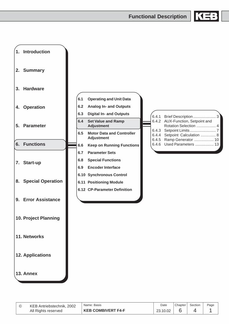
6 4 1KEB COMBIVERT F4-F
Name: Basis
Functional Description
Chapter Section PageDate© KEB Antriebstechnik, 2002All Rights reserved 23.10.02
6.1 Operating and Unit Data
6.2 Analog In- and Outputs
6.3 Digital In- and Outputs
6.4 Set Value and RampAdjustment
6.5 Motor Data and ControllerAdjustment
6.6 Keep on Running Functions
6.7 Parameter Sets
6.8 Special Functions
6.9 Encoder Interface
6.10 Synchronous Control
6.11 Positioning Module
6.12 CP-Parameter Definition
1. Introduction
2. Summary
3. Hardware
4. Operation
5. Parameter
6. Functions
7. Start-up
8. Special Operation
9. Error Assistance
10. Project Planning
11. Networks
12. Applications
13. Annex
6.4.1 Brief Description ..................... 36.4.2 AUX-Function, Setpoint and
Rotation Selection .................. 46.4.3 Setpoint Limits ........................ 76.4.4 Setpoint Calculation .............. 86.4.5 Ramp Generator .................. 106.4.6 Used Parameters ................. 13

4 26Name: Basis
KEB COMBIVERT F4-F23.10.02
Functional Description Set Value and Ramp Adjustment
Chapter Section Page Date © KEB Antriebstechnik, 2002All Rights reserved
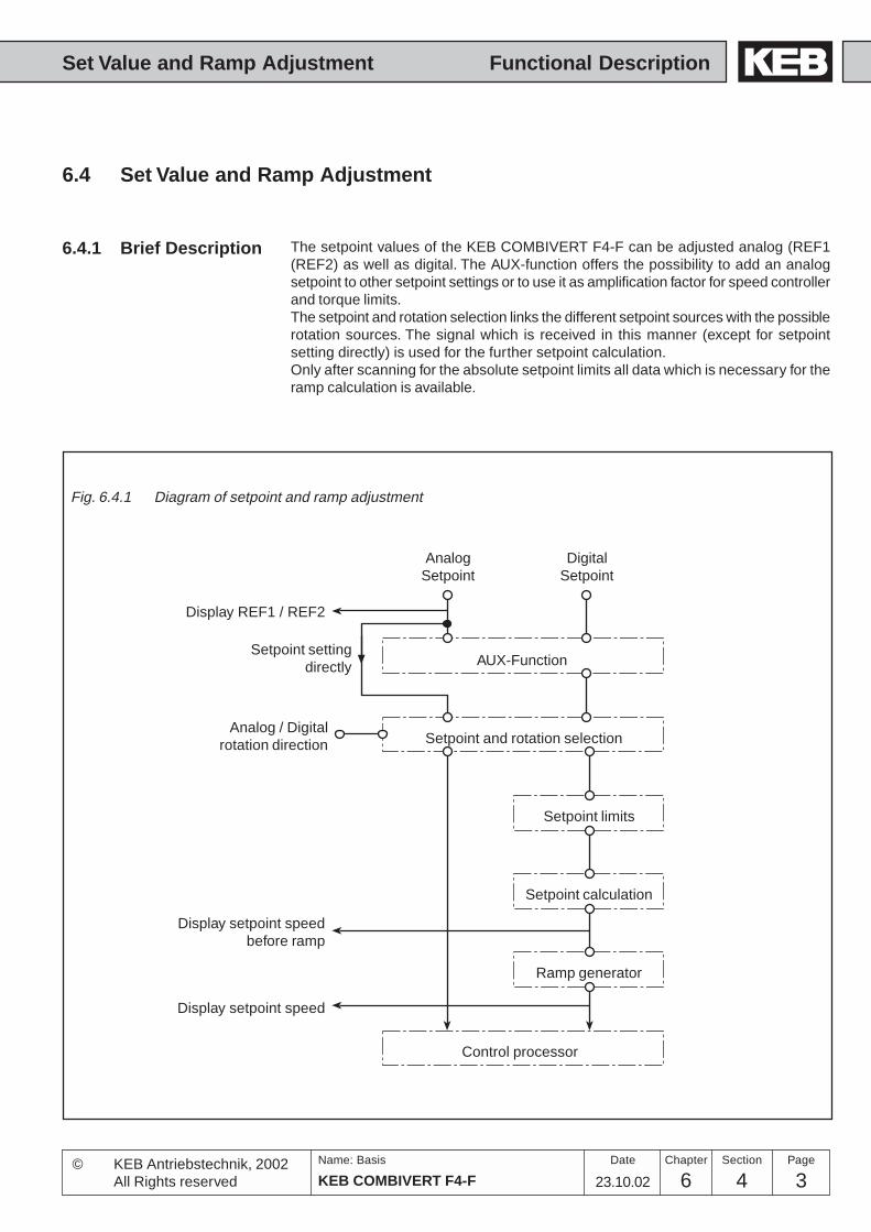
6 4 3KEB COMBIVERT F4-F
Name: Basis
Functional DescriptionSet Value and Ramp Adjustment
Chapter Section PageDate© KEB Antriebstechnik, 2002All Rights reserved 23.10.02
6.4.1 Brief Description
6.4 Set Value and Ramp Adjustment
Fig. 6.4.1 Diagram of setpoint and ramp adjustment
The setpoint values of the KEB COMBIVERT F4-F can be adjusted analog (REF1(REF2) as well as digital. The AUX-function offers the possibility to add an analogsetpoint to other setpoint settings or to use it as amplification factor for speed controllerand torque limits.The setpoint and rotation selection links the different setpoint sources with the possiblerotation sources. The signal which is received in this manner (except for setpointsetting directly) is used for the further setpoint calculation.Only after scanning for the absolute setpoint limits all data which is necessary for theramp calculation is available.
DigitalSetpoint
AnalogSetpoint
Setpoint settingdirectly AUX-Function
Setpoint and rotation selection
Setpoint limits
Setpoint calculation
Ramp generator
Control processor
Analog / Digitalrotation direction
Display REF1 / REF2
Display setpoint speedbefore ramp
Display setpoint speed
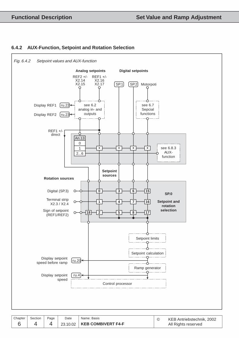
4 46Name: Basis
KEB COMBIVERT F4-F23.10.02
Functional Description Set Value and Ramp Adjustment
Chapter Section Page Date © KEB Antriebstechnik, 2002All Rights reserved
0
1
2
3
4
518
6
7
8
15
16
17
+ + + +
An.1301
2...6
Fig. 6.4.2 Setpoint values and AUX-function
Analog setpoints Digital setpoints
see 6.7Sepcial
functions
see 6.2analog in- and
outputs
REF2 +/-X2.14X2.15
REF1 +/-X2.16X2.17 SP.1 SP.2 Motorpoti
REF1 +/-direct
6.4.2 AUX-Function, Setpoint and Rotation Selection
Setpointsources
Setpoint limits
Setpoint calculation
Ramp generator
Control processor
SP.0
Setpoint androtation
selection
Rotation sources
Digital (SP.3)
Terminal stripX2.3 / X2.4
Sign of setpoint(REF1/REF2)
Display setpointspeed before ramp ru.20
Display setpointspeed
ru.4
Display REF1 ru.22
Display REF2 ru.23
see 6.8.3AUX-
function
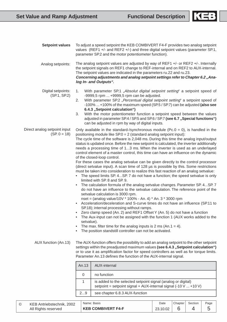
6 4 5KEB COMBIVERT F4-F
Name: Basis
Functional DescriptionSet Value and Ramp Adjustment
Chapter Section PageDate© KEB Antriebstechnik, 2002All Rights reserved 23.10.02
The AUX-function offers the possibility to add an analog setpoint to the other setpointsettings within the preadjusted maximum values (see 6.4.3 „Setpoint calculation“)or to use it as amplification factor for speed controllers as well as for torque limits.Parameter An.13 defines the function of the AUX-internal signal.
An.13 AUX-internal
0 no function
1 is added to the selected setpoint signal (analog or digital)setpoint = setpoint signal + AUX-internal signal (-10 V ... +10 V)
2...9 see chapter 6.8.3 AUX-function
To adjust a speed setpoint the KEB COMBIVERT F4-F provides two analog setpointvalues (REF1 +/- and REF2 +/-) and three digital setpoint values (parameter SP.1,parameter SP.2 and the motor potentiometer function).
The analog setpoint values are adjusted by way of REF1 +/- or REF2 +/-. Internallythe setpoint signals on REF1 change to REF-internal and on REF2 to AUX-internal.The setpoint values are indicated in the parameters ru.22 and ru.23.Concerning adjustments and analog setpoint settings refer to Chapter 6.2 „Ana-log In- and Outputs“.
1. With parameter SP.1 „Absolut digital setpoint setting“ a setpoint speed of-9999,5 rpm ... +9999,5 rpm can be adjusted.
2. With parameter SP.2 „Percentual digital setpoint setting“ a setpoint speed of-100% ... +100% of the maximum speed (SP.5 / SP.7) can be adjusted (also see6.4.3 „Setpoint calculation“)
3. With the motor potentiometer function a setpoint speed between the valuesadjusted in parameter SP.4 / SP.5 and SP.6 / SP.7 (see 6.7 „Special functions“)can be adjusted in rpm by way of digital inputs.
Setpoint values
AUX function (An.13)
Analog setpoints:
Digital setpoints:(SP.1, SP.2)
Only available in the standard-/synchronous module (Pc.0 = 0), is handled in thepositioning module like SP.0 = 2 (standard analog setpoint input):The cycle time of the software is 2,048 ms. During this time the analog input/outputstatus is updated once. Before the new setpoint is calculated, the inverter additionallyneeds a processing time of 1...3 ms. When the inverter is used as an underlayedcontrol element of a master control, this time can have an influence on the dynamicof the closed-loop control.For these cases the analog setvalue can be given directly to the control processor(direct setvalue input). A scan time of 128 µs is possible by this. Some restrictionsmust be taken into consideration to realize this fast reaction of an analog setvalue:• The speed limits SP. 4...SP. 7 do not have a function; the speed setvalue is only
limited with SP. 8 and SP. 9.• The calculation formula of the analog setvalue changes. Parameter SP. 4...SP. 7
do not have an influence to the setvalue calculation. The reference point of thesetvalue calculation is 3000 rpm.nset = (analog value/10V * 100% - An. 4) * An. 3 * 3000 rpm
• Acceleration/deceleration and S-curve times do not have an influence (SP.11 toSP.18); internal processing without ramps.
• Zero clamp speed (An. 2) and REF1 Offset Y (An. 5) do not have a function• The Aux-input can not be assigned with the function 1 (AUX works added to the
setvalue).• The max. filter time for the analog inputs is 2 ms (An.1 = 4).• The position standstill controller can not be activated.
Direct analog setpoint input(SP. 0 = 18)
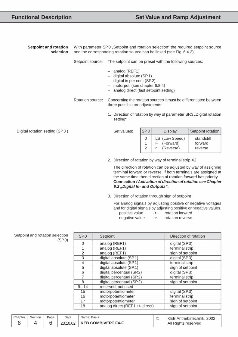
4 66Name: Basis
KEB COMBIVERT F4-F23.10.02
Functional Description Set Value and Ramp Adjustment
Chapter Section Page Date © KEB Antriebstechnik, 2002All Rights reserved
Digital rotation setting (SP.3 )
With parameter SP.0 „Setpoint and rotation selection“ the required setpoint sourceand the corresponding rotation source can be linked (see Fig. 6.4.2).
Setpoint source: The setpoint can be preset with the following sources:
– analog (REF1)– digital absolute (SP.1)– digital in per cent (SP.2)– motorpoti (see chapter 6.8.4)– analog direct (fast setpoint setting)
Rotation source: Concerning the rotation sources it must be differentiated betweenthree possible preadjustments:
1. Direction of rotation by way of parameter SP.3 „Digital rotationsetting“
Set values: SP.3 Display Setpoint rotation
0 LS (Low Speed) standstill1 F (Forward) forward2 r (Reverse) reverse
2. Direction of rotation by way of terminal strip X2
The direction of rotation can be adjusted by way of assigningterminal forward or reverse. If both terminals are assigned atthe same time then direction of rotation forward has priority.Connection / Activation of direction of rotation see Chapter6.3 „Digital In- and Outputs“.
3. Direction of rotation through sign of setpoint
For analog signals by adjusting positive or negative voltagesand for digital signals by adjusting positive or negative values.
positive value -> rotation forwardnegative value -> rotation reverse
Setpoint and rotationselection
SP.0 Setpoint Direction of rotation
0 analog (REF1) digital (SP.3)1 analog (REF1) terminal strip2 analog (REF1) sign of setpoint3 digital absolute (SP.1) digital (SP.3)4 digital absolute (SP.1) terminal strip5 digital absolute (SP.1) sign of setpoint6 digital percentual (SP.2) digital (SP.3)7 digital percentual (SP.2) terminal strip8 digital percentual (SP.2) sign of setpoint
9...14 reserved, not used15 motorpotentiometer digital (SP.3)16 motorpotentiometer terminal strip17 motorpotentiometer sign of setpoint18 analog direct (REF1 +/- direct) sign of setpoint
Setpoint and rotation selection(SP.0)
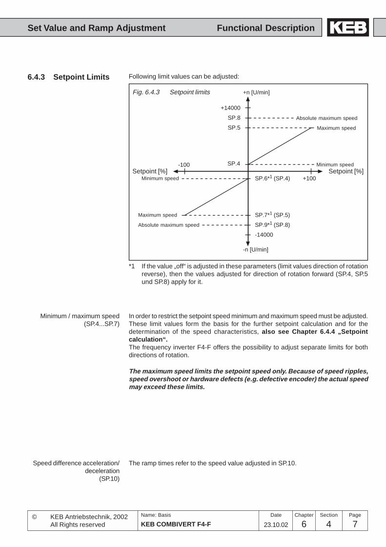
6 4 7KEB COMBIVERT F4-F
Name: Basis
Functional DescriptionSet Value and Ramp Adjustment
Chapter Section PageDate© KEB Antriebstechnik, 2002All Rights reserved 23.10.02
+n [U/min]
-n [U/min]
+14000
SP.6*1 (SP.4)
-14000
SP.4
SP.8
SP.5
SP.9*1 (SP.8)
SP.7*1 (SP.5)
+100
-100
Absolute maximum speed
6.4.3 Setpoint Limits Following limit values can be adjusted:
Setpoint [%]Setpoint [%]Minimum speed
Maximum speed
Absolute maximum speed
Maximum speed
Minimum speed
*1 If the value „off“ is adjusted in these parameters (limit values direction of rotationreverse), then the values adjusted for direction of rotation forward (SP.4, SP.5und SP.8) apply for it.
In order to restrict the setpoint speed minimum and maximum speed must be adjusted.These limit values form the basis for the further setpoint calculation and for thedetermination of the speed characteristics, also see Chapter 6.4.4 „Setpointcalculation“.The frequency inverter F4-F offers the possibility to adjust separate limits for bothdirections of rotation.
Minimum / maximum speed(SP.4...SP.7)
Fig. 6.4.3 Setpoint limits
The maximum speed limits the setpoint speed only. Because of speed ripples,speed overshoot or hardware defects (e.g. defective encoder) the actual speedmay exceed these limits.
Speed difference acceleration/deceleration
(SP.10)
The ramp times refer to the speed value adjusted in SP.10.
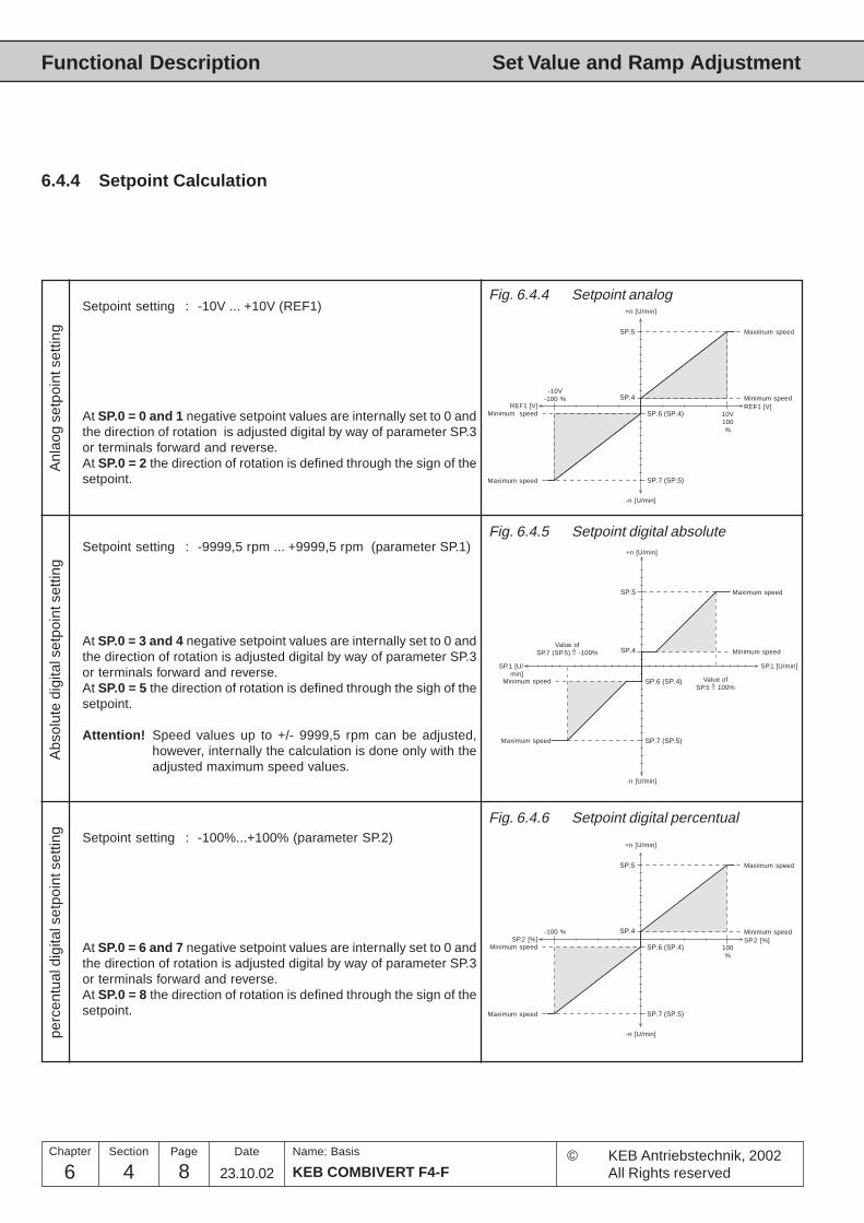
4 86Name: Basis
KEB COMBIVERT F4-F23.10.02
Functional Description Set Value and Ramp Adjustment
Chapter Section Page Date © KEB Antriebstechnik, 2002All Rights reserved
SP.4
SP.5
SP.6 (SP.4)
SP.7 (SP.5)
SP.4
SP.5
SP.6 (SP.4)
SP.7 (SP.5)
SP.4
SP.5
SP.6 (SP.4)
SP.7 (SP.5)
6.4.4 Setpoint Calculation
Setpoint setting : -10V ... +10V (REF1)
At SP.0 = 0 and 1 negative setpoint values are internally set to 0 andthe direction of rotation is adjusted digital by way of parameter SP.3or terminals forward and reverse.At SP.0 = 2 the direction of rotation is defined through the sign of thesetpoint.
Setpoint setting : -9999,5 rpm ... +9999,5 rpm (parameter SP.1)
At SP.0 = 3 and 4 negative setpoint values are internally set to 0 andthe direction of rotation is adjusted digital by way of parameter SP.3or terminals forward and reverse.At SP.0 = 5 the direction of rotation is defined through the sigh of thesetpoint.
Attention! Speed values up to +/- 9999,5 rpm can be adjusted,however, internally the calculation is done only with theadjusted maximum speed values.
+n [U/min]
-n [U/min]
Maximum speed
Minimum speed
Minimum speed
Maximum speed
+n [U/min]
Maximum speed
Minimum speed
Minimum speed
Maximum speed
Value ofSP.7 (SP.5) = -100%
Value ofSP.5 = 100%
SP.1 [U/min]
Anl
aog
setp
oint
set
ting
Abs
olut
e di
gita
l set
poin
t set
ting
Setpoint setting : -100%...+100% (parameter SP.2)
At SP.0 = 6 and 7 negative setpoint values are internally set to 0 andthe direction of rotation is adjusted digital by way of parameter SP.3or terminals forward and reverse.At SP.0 = 8 the direction of rotation is defined through the sign of thesetpoint.
perc
entu
al d
igita
l set
poin
t set
ting
REF1 [V] REF1 [V]10V100%
-10V-100 %
+n [U/min]
-n [U/min]
Maximum speed
Minimum speed
Minimum speed
Maximum speed
SP.2 [%] SP.2 [%]100%
-100 %
SP.1 [U/min]
Fig. 6.4.4 Setpoint analog
Fig. 6.4.5 Setpoint digital absolute
Fig. 6.4.6 Setpoint digital percentual
-n [U/min]
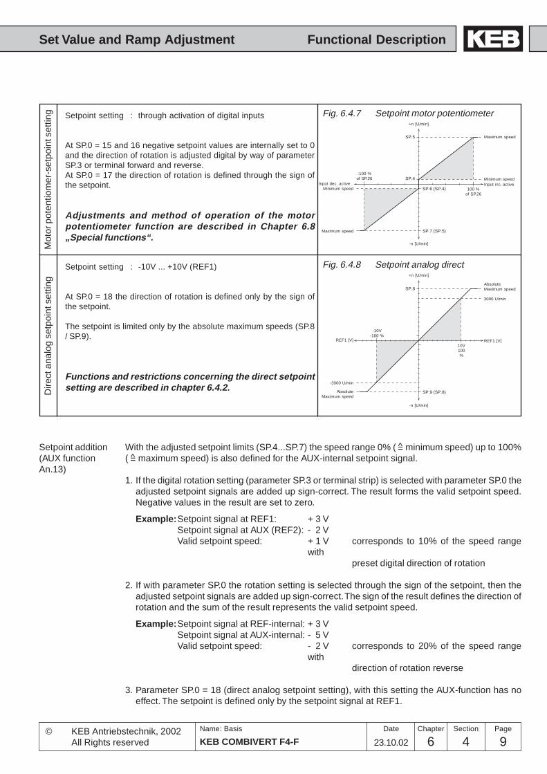
6 4 9KEB COMBIVERT F4-F
Name: Basis
Functional DescriptionSet Value and Ramp Adjustment
Chapter Section PageDate© KEB Antriebstechnik, 2002All Rights reserved 23.10.02
SP.4
SP.5
SP.6 (SP.4)
SP.7 (SP.5)
SP.8
SP.9 (SP.8)
Fig. 6.4.7 Setpoint motor potentiometerSetpoint setting : through activation of digital inputs
At SP.0 = 15 and 16 negative setpoint values are internally set to 0and the direction of rotation is adjusted digital by way of parameterSP.3 or terminal forward and reverse.At SP.0 = 17 the direction of rotation is defined through the sign ofthe setpoint.
Adjustments and method of operation of the motorpotentiometer function are described in Chapter 6.8„Special functions“.
Mot
or p
oten
tiom
er-s
etpo
int s
ettin
g
+n [U/min]
-n [U/min]
Maximum speed
Minimum speed
Minimum speed
Maximum speed
Input dec. active Input inc. active100 %
of SP.26
-100 %of SP.26
Setpoint addition(AUX functionAn.13)
With the adjusted setpoint limits (SP.4...SP.7) the speed range 0% ( = minimum speed) up to 100%( = maximum speed) is also defined for the AUX-internal setpoint signal.
1. If the digital rotation setting (parameter SP.3 or terminal strip) is selected with parameter SP.0 theadjusted setpoint signals are added up sign-correct. The result forms the valid setpoint speed.Negative values in the result are set to zero.
Example:Setpoint signal at REF1: + 3 VSetpoint signal at AUX (REF2): - 2 VValid setpoint speed: + 1 V corresponds to 10% of the speed range
withpreset digital direction of rotation
2. If with parameter SP.0 the rotation setting is selected through the sign of the setpoint, then theadjusted setpoint signals are added up sign-correct. The sign of the result defines the direction ofrotation and the sum of the result represents the valid setpoint speed.
Example:Setpoint signal at REF-internal: + 3 VSetpoint signal at AUX-internal: - 5 VValid setpoint speed: - 2 V corresponds to 20% of the speed range
withdirection of rotation reverse
3. Parameter SP.0 = 18 (direct analog setpoint setting), with this setting the AUX-function has noeffect. The setpoint is defined only by the setpoint signal at REF1.
Setpoint setting : -10V ... +10V (REF1)
At SP.0 = 18 the direction of rotation is defined only by the sign ofthe setpoint.
The setpoint is limited only by the absolute maximum speeds (SP.8/ SP.9).
Functions and restrictions concerning the direct setpointsetting are described in chapter 6.4.2.
+n [U/min]
-n [U/min]
AbsoluteMaximum speed
3000 U/min
-3000 U/min
AbsoluteMaximum speed
Dire
ct a
nalo
g se
tpoi
nt s
ettin
g
REF1 [V] REF1 [V]10V100%
-10V-100 %
Fig. 6.4.8 Setpoint analog direct
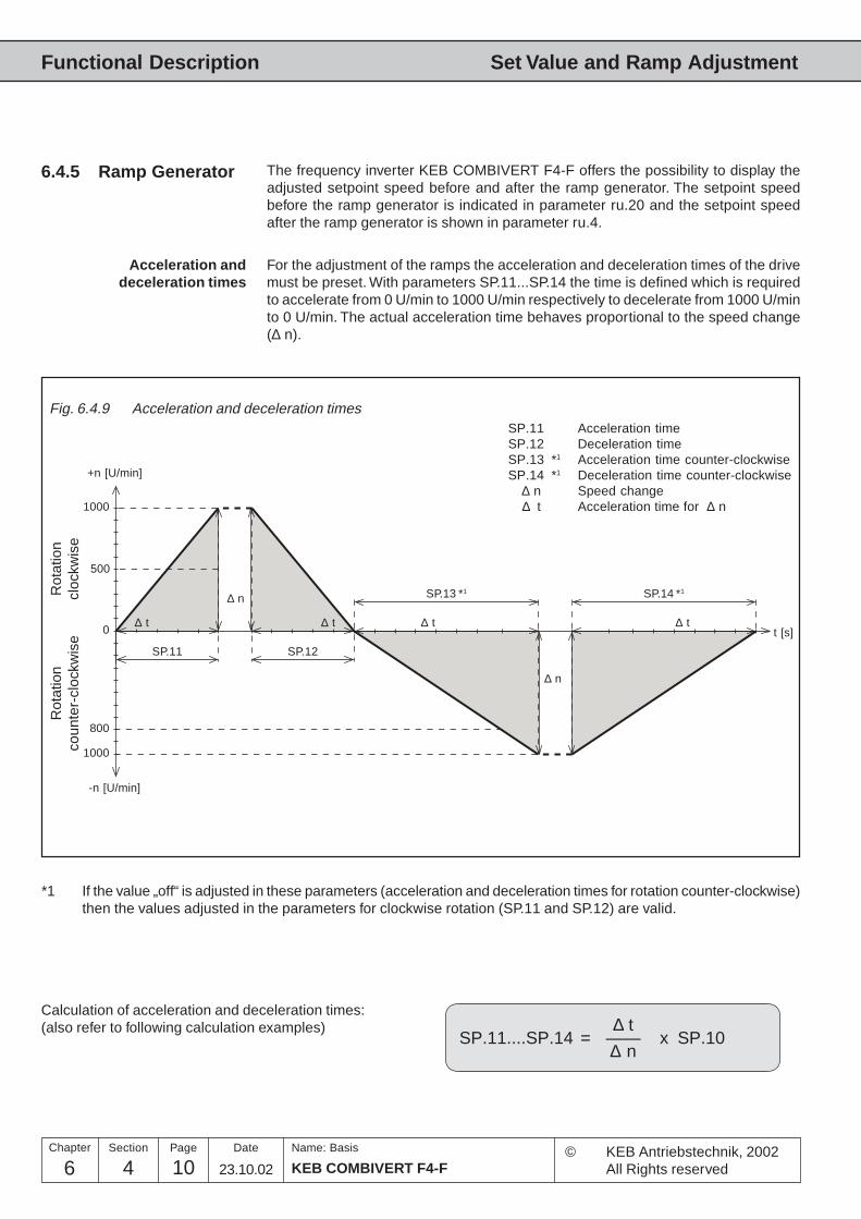
4 106Name: Basis
KEB COMBIVERT F4-F23.10.02
Functional Description Set Value and Ramp Adjustment
Chapter Section Page Date © KEB Antriebstechnik, 2002All Rights reserved
1000
800
0
1000
500
∆ t
SP.11
∆ n
∆ t
SP.12
∆ t
∆ n
SP.13 *1
∆ t
SP.14 *1
t [s]
For the adjustment of the ramps the acceleration and deceleration times of the drivemust be preset. With parameters SP.11...SP.14 the time is defined which is requiredto accelerate from 0 U/min to 1000 U/min respectively to decelerate from 1000 U/minto 0 U/min. The actual acceleration time behaves proportional to the speed change(∆ n).
6.4.5 Ramp Generator
+n [U/min]
-n [U/min]
Rot
atio
ncl
ockw
ise
Rot
atio
nco
unte
r-cl
ockw
ise
SP.11 Acceleration timeSP.12 Deceleration timeSP.13 *1 Acceleration time counter-clockwiseSP.14 *1 Deceleration time counter-clockwise
∆ n Speed change∆ t Acceleration time for ∆ n
Fig. 6.4.9 Acceleration and deceleration times
Calculation of acceleration and deceleration times:(also refer to following calculation examples) ∆ t
SP.11....SP.14 = —— x SP.10∆ n
Acceleration anddeceleration times
*1 If the value „off“ is adjusted in these parameters (acceleration and deceleration times for rotation counter-clockwise)then the values adjusted in the parameters for clockwise rotation (SP.11 and SP.12) are valid.
The frequency inverter KEB COMBIVERT F4-F offers the possibility to display theadjusted setpoint speed before and after the ramp generator. The setpoint speedbefore the ramp generator is indicated in parameter ru.20 and the setpoint speedafter the ramp generator is shown in parameter ru.4.
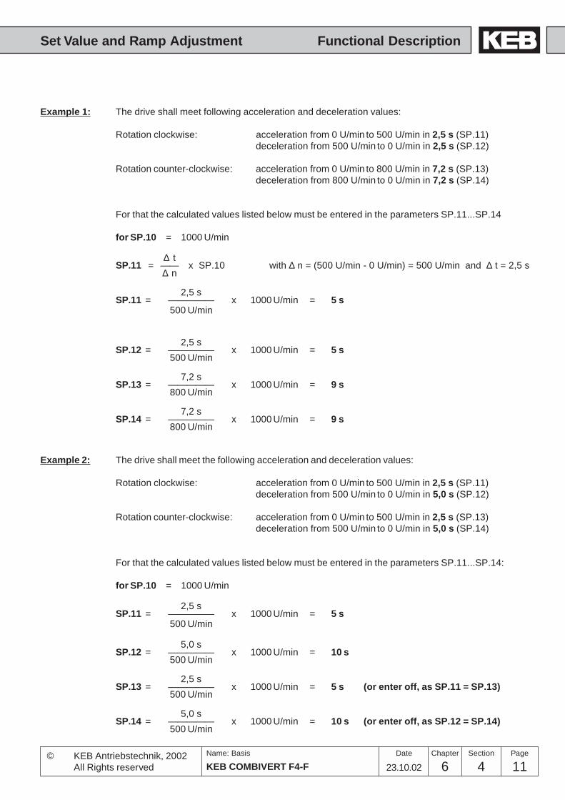
6 4 11KEB COMBIVERT F4-F
Name: Basis
Functional DescriptionSet Value and Ramp Adjustment
Chapter Section PageDate© KEB Antriebstechnik, 2002All Rights reserved 23.10.02
Example 1: The drive shall meet following acceleration and deceleration values:
Rotation clockwise: acceleration from 0 U/min to 500 U/min in 2,5 s (SP.11)deceleration from 500 U/min to 0 U/min in 2,5 s (SP.12)
Rotation counter-clockwise: acceleration from 0 U/min to 800 U/min in 7,2 s (SP.13)deceleration from 800 U/min to 0 U/min in 7,2 s (SP.14)
For that the calculated values listed below must be entered in the parameters SP.11...SP.14
for SP.10 = 1000 U/min
∆ tSP.11 = —— x SP.10 with ∆ n = (500 U/min - 0 U/min) = 500 U/min and ∆ t = 2,5 s
∆ n
2,5 sSP.11 = ————— x 1000 U/min = 5 s
500 U/min
2,5 sSP.12 = ————— x 1000 U/min = 5 s
500 U/min
7,2 sSP.13 = ————— x 1000 U/min = 9 s
800 U/min
7,2 sSP.14 = ————— x 1000 U/min = 9 s
800 U/min
Example 2: The drive shall meet the following acceleration and deceleration values:
Rotation clockwise: acceleration from 0 U/min to 500 U/min in 2,5 s (SP.11)deceleration from 500 U/min to 0 U/min in 5,0 s (SP.12)
Rotation counter-clockwise: acceleration from 0 U/min to 500 U/min in 2,5 s (SP.13)deceleration from 500 U/min to 0 U/min in 5,0 s (SP.14)
For that the calculated values listed below must be entered in the parameters SP.11...SP.14:
for SP.10 = 1000 U/min
2,5 sSP.11 = ————— x 1000 U/min = 5 s
500 U/min
5,0 sSP.12 = ————— x 1000 U/min = 10 s
500 U/min
2,5 sSP.13 = ————— x 1000 U/min = 5 s (or enter off, as SP.11 = SP.13)
500 U/min
5,0 sSP.14 = ————— x 1000 U/min = 10 s (or enter off, as SP.12 = SP.14)
500 U/min
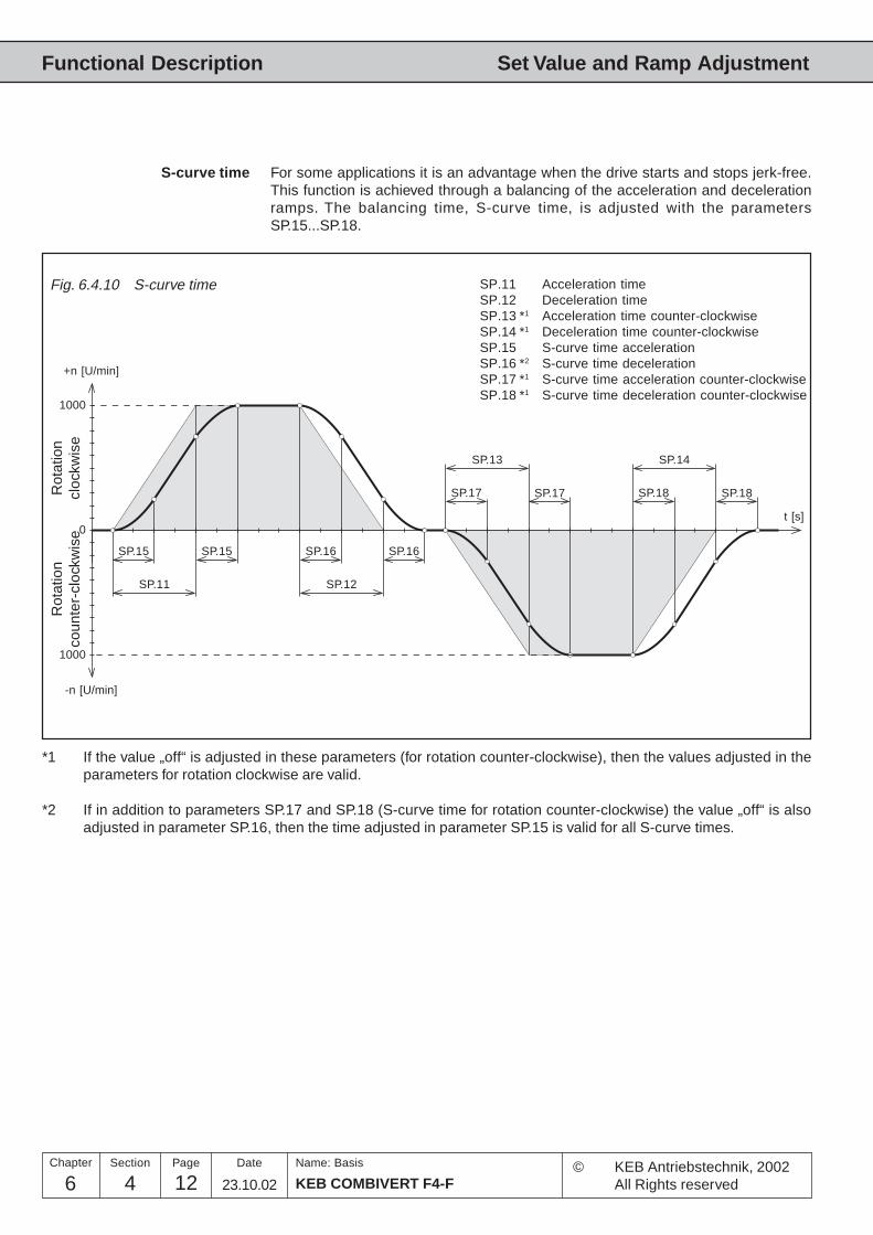
4 126Name: Basis
KEB COMBIVERT F4-F23.10.02
Functional Description Set Value and Ramp Adjustment
Chapter Section Page Date © KEB Antriebstechnik, 2002All Rights reserved
SP.11
t [s]
SP.15 SP.15
SP.12
SP.16 SP.16
SP.17
SP.13
SP.17 SP.18
SP.14
SP.18
1000
1000
0
For some applications it is an advantage when the drive starts and stops jerk-free.This function is achieved through a balancing of the acceleration and decelerationramps. The balancing time, S-curve time, is adjusted with the parametersSP.15...SP.18.
S-curve time
+n [U/min]
-n [U/min]
Rot
atio
ncl
ockw
ise
Rot
atio
nco
unte
r-cl
ockw
ise
Fig. 6.4.10 S-curve time SP.11 Acceleration timeSP.12 Deceleration timeSP.13 *1 Acceleration time counter-clockwiseSP.14 *1 Deceleration time counter-clockwiseSP.15 S-curve time accelerationSP.16 *2 S-curve time decelerationSP.17 *1 S-curve time acceleration counter-clockwiseSP.18 *1 S-curve time deceleration counter-clockwise
*1 If the value „off“ is adjusted in these parameters (for rotation counter-clockwise), then the values adjusted in theparameters for rotation clockwise are valid.
*2 If in addition to parameters SP.17 and SP.18 (S-curve time for rotation counter-clockwise) the value „off“ is alsoadjusted in parameter SP.16, then the time adjusted in parameter SP.15 is valid for all S-curve times.
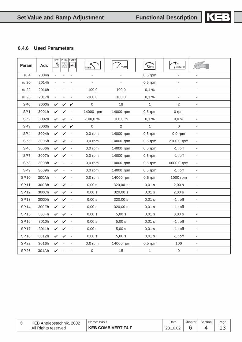
6 4 13KEB COMBIVERT F4-F
Name: Basis
Functional DescriptionSet Value and Ramp Adjustment
Chapter Section PageDate© KEB Antriebstechnik, 2002All Rights reserved 23.10.02
StepParam. Adr.ENTERPROG.R/W
min max default
ru.4 2004h - - - - - 0,5 rpm - -
ru.20 2014h - - - - - 0,5 rpm - -
ru.22 2016h - - - -100,0 100,0 0,1 % - -
ru.23 2017h - - - -100,0 100,0 0,1 % - -
SP.0 3000h 0 18 1 2 -
SP.1 3001h - -14000 rpm 14000 rpm 0,5 rpm 0 rpm -
SP.2 3002h - -100,0 % 100,0 % 0,1 % 0,0 % -
SP.3 3003h 0 2 1 0 -
SP.4 3004h - 0,0 rpm 14000 rpm 0,5 rpm 0,0 rpm -
SP.5 3005h - 0,0 rpm 14000 rpm 0,5 rpm 2100,0 rpm -
SP.6 3006h - 0,0 rpm 14000 rpm 0,5 rpm -1 : off -
SP.7 3007h - 0,0 rpm 14000 rpm 0,5 rpm -1 : off -
SP.8 3008h - - 0,0 rpm 14000 rpm 0,5 rpm 6000,0 rpm -
SP.9 3009h - - 0,0 rpm 14000 rpm 0,5 rpm -1 : off -
SP.10 300Ah - - 0,0 rpm 14000 rpm 0,5 rpm 1000 rpm -
SP.11 300Bh - 0,00 s 320,00 s 0,01 s 2,00 s -
SP.12 300Ch - 0,00 s 320,00 s 0,01 s 2,00 s -
SP.13 300Dh - 0,00 s 320,00 s 0,01 s -1 : off -
SP.14 300Eh - 0,00 s 320,00 s 0,01 s -1 : off -
SP.15 300Fh - 0,00 s 5,00 s 0,01 s 0,00 s -
SP.16 3010h - 0,00 s 5,00 s 0,01 s -1 : off -
SP.17 3011h - 0,00 s 5,00 s 0,01 s -1 : off -
SP.18 3012h - 0,00 s 5,00 s 0,01 s -1 : off -
SP.22 3016h - - 0,0 rpm 14000 rpm 0,5 rpm 100 -
SP.26 301Ah - - 0 15 1 0 -
6.4.6 Used Parameters

4 146Name: Basis
KEB COMBIVERT F4-F23.10.02
Chapter Section Page Date
Functional Description
© KEB Antriebstechnik, 2002All Rights reserved
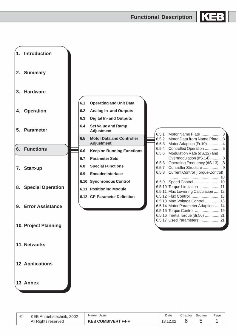
6 5 1KEB COMBIVERT F4-F
Name: Basis
18.12.02
Functional Description
Chapter Section PageDate© KEB Antriebstechnik, 2002All Rights reserved
1. Introduction
2. Summary
3. Hardware
4. Operation
5. Parameter
6. Functions
7. Start-up
8. Special Operation
9. Error Assistance
10. Project Planning
11. Networks
12. Applications
13. Annex
6.1 Operating and Unit Data
6.2 Analog In- and Outputs
6.3 Digital In- and Outputs
6.4 Set Value and RampAdjustment
6.5 Motor Data and ControllerAdjustment
6.6 Keep on Running Functions
6.7 Parameter Sets
6.8 Special Functions
6.9 Encoder Interface
6.10 Synchronous Control
6.11 Positioning Module
6.12 CP-Parameter Definition
6.5.1 Motor Name Plate ................... 36.5.2 Motor Data from Name Plate .. 36.5.3 Motor Adaption (Fr.10) ............ 46.5.4 Controlled Operation ............... 56.5.5 Modulation Rate (dS.12) and
Overmodulation (dS.14) .......... 86.5.6 Operating Frequency (dS.13) .. 86.5.7 Controller Structure ................. 96.5.8 Current Control (Torque Control)
............................................. 106.5.9 Speed Control ....................... 106.5.10 Torque Limitation .................. 116.5.11 Flux Lowering Calculation ..... 126.5.12 Flux Control .......................... 136.5.13 Max. Voltage Control ............. 136.5.14 Motor Parameter Adaption .... 146.5.15 Torque Control ...................... 196.5.16 Inertia Torque (dr.56) ............. 216.5.17 Used Parameters .................. 21

6 5 KEB COMBIVERT F4-F2Name: Basis
18.12.02
Chapter Section Page Date © KEB Antriebstechnik, 2002All Rights reserved
Functional Description Motor Data and Controller Adjustment
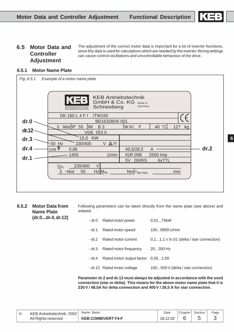
36 5 3KEB COMBIVERT F4-F
Name: Basis
18.12.02
6
Section PageDate© KEB Antriebstechnik, 2002All Rights reserved
Chapter
Functional DescriptionMotor Data and Controller Adjustment
ANTRIEBSTECHNIK
KEB AntriebstechnikGmbH & Co. KGSchneeberg
Made inGermany
-Mot IP IM W.KI. °C kg
Hz Vcos
/Y
1/min
U V~Mot Hz Nm mm
FL
MBr ISp max
DK 160 L 4 F I /TW15096/1632804/ 001
3 55 B 3 F 40 127VDE 053 0
15,0 KW
ϕ50 230/400
0,861455
230/4003 50
49,5/28,5 AIGR 05B 2500 Imp5V D0/RS 6xTTLdr.1
dr.2
dr.3
dr.4
dr.12
dr.0
6.5 Motor Data andControllerAdjustment
Fig. 6.5.1 Example of a motor name plate
6.5.1 Motor Name Plate
The adjustment of the correct motor data is important for a lot of inverter functions,since this data is used for calculations which are needed by the inverter. Wrong settingscan cause control oscillations and uncontrollable behaviour of the drive.
6.5.2 Motor Data fromName Plate(dr.0...dr.4, dr.12)
Following parameters can be taken directly from the name plate (see above) andentered:
- dr.0 Rated motor power 0,01...75kW
- dr.1 Rated motor speed 100...9999 U/min
- dr.2 Rated motor current 0,1...1,1 x In.01 (delta / star connection)
- dr.3 Rated motor frequency 20...300 Hz
- dr.4 Rated motor output factor 0,05...1,00
- dr.12 Rated motor voltage 100...500 V (delta / star connection)
Parameter dr.2 and dr.12 must always be adjusted in accordance with the usedconnection (star or delta). This means for the above motor name plate that it is230 V / 48,5A for delta connection and 400 V / 28,5 A for star connection.
6 5 KEB COMBIVERT F4-F4Name: Basis
18.12.02
Chapter Section Page Date © KEB Antriebstechnik, 2002All Rights reserved
Functional Description Motor Data and Controller Adjustment
6.5.3 Motor Adaption(Fr.10)
After entering the name plate specifications of a new motor parameter Fr.10 should beactivated once (inverter must be in status nOP). This creates a default setting for anumber of control parameters which is sufficient for many applications. This adjustmentdepends on inverter identification data (like e.g. rated inverter current) and motoridentification data (like e.g. motor rating and rated motor current).
Parameters which are changed through the activation of Fr.10:
• dr.13 Speed for maximum torque• dr.16 Maximum torque corner speed• dr.19 Corner speed field weakening• dr.20 Field weakening curve• dr.21 Flux adaption factor• dS.0 KP I active• dS.1 KI I active• dS.5 KP I magnetizing• dS.6 KI I magnetizing• CS.6/CS.7/CS.8/CS.9 torque limits• Pn.60 torque for abnormal stop• CS.19 KP flux• CS.20 KI flux• Cs.21 magn. current limit
On the basis of these settings a fine adustment can be carried out, e.g. an increaseof the torque limits or a change of the field weakening time.
Control of the optimized settings: Over the entire speed range the modulation factorshould not exceed approx. 90 .. 95 % (depending on the expected system fluctuationsand temperature changes). However, the output voltage at the rated point should notbe too low (e.g. modulation factor at rated speed and rated load < 70 %), since such asetting would result in a motor current that is too high.
Procedure:1. Open control release (status nOP)2. Enter motor name plate data in the corresponding parameters (dr.0...12).3. Adjust Fr.10 = 1 or Fr.10 = 2 ⇒ the corresponding dr/dS parameters are loaded
with the default-parameters.4. If necessary, carry out a fine adjustment on the basis of these settings.
Value Meaning1, 2 Pre-adjustment of the motor-dependent control-parameters for standard
operation (without adaption / CS.10 = 0)The equivalent circuit data of dr.48...dr.52 are not needed.
3...6 These values are only needed at operations with adaption.
56 5 5KEB COMBIVERT F4-F
Name: Basis
18.12.02
6
Section PageDate© KEB Antriebstechnik, 2002All Rights reserved
Chapter
Functional DescriptionMotor Data and Controller Adjustment
With CS.23 all of the controller functions are activated/deactivated.
CS.23 Function0 open loop operation (inverter performs according to U/f-characteristic)1 closed loop operation
6.5.4 Control Method
The control method is suited only as emergency operation for set up or in case of afaulty encoder.
Increased oscillating torque compared to controlled operation.
Continues to indicate the actual speed measured by encoder 1.
Active current and actual torque are internally set to zero, i.e. ru.2 and ru.10 alwaysdisplay the value 0. If outputs are programmed to torque-dependent switching or if atorque signal is given out over an analog output then the outputs behave like they doat actual torque/active current = 0.
Indicates the actual output frequency converted into min-1
ru.4 = x 60
Serve for the calculation of the pole pair number, for that reason they must be adjustedcorrectly even in controlled operation.
Define the voltage/frequency-characteristic.
If the speed control is deactivated then all torque limits are without effect.
Are without function in controlled operation. speed and flow controller are not active.
Only dS.10 (voltage stabilization) and dS.11 (Boost) are still effective.
The controlled operation can be activated in the synchronous module (Pc.0 = on) andthe positioning module (Pd.0 = on). The positioning (Pd.0 = on) or synchronous control(Sn.0 = on) should be activated only at switched on speed control, otherwise thepositioning control is very instable.
ru.1
Restrictions
ru.2/ru.10
ru.4
Output frequency
Pole pair number
dr.1/dr.3
dr.3/dr.12/ds.11/ds.10
dr.13/dr.16
CS-Parameter
dS-Parameter
Sn-ParameterPd-Parameter
uneven values (1, 3, 5): the adjusted voltage value (dS.10 or, in case dS.10 is notactivated, the voltage class of the inverter is used as reference value for the calculationof motor-dependent parameters.
even values (2, 4, 6): the DC-link voltage / √2 measured at the switch is used asreference value for the calculation of motor-dependent parameters.
This means: If the parameterizing of an inverter is done e.g. at a system input voltageof 400 V, while the drive operates later on a 460 V system, then either parameterFr.10 = 2 must be written again or the inverter must already be parameterized on the400V-system by means of dS.10 = 460V and Fr.10 = 1 for the 460 V system.
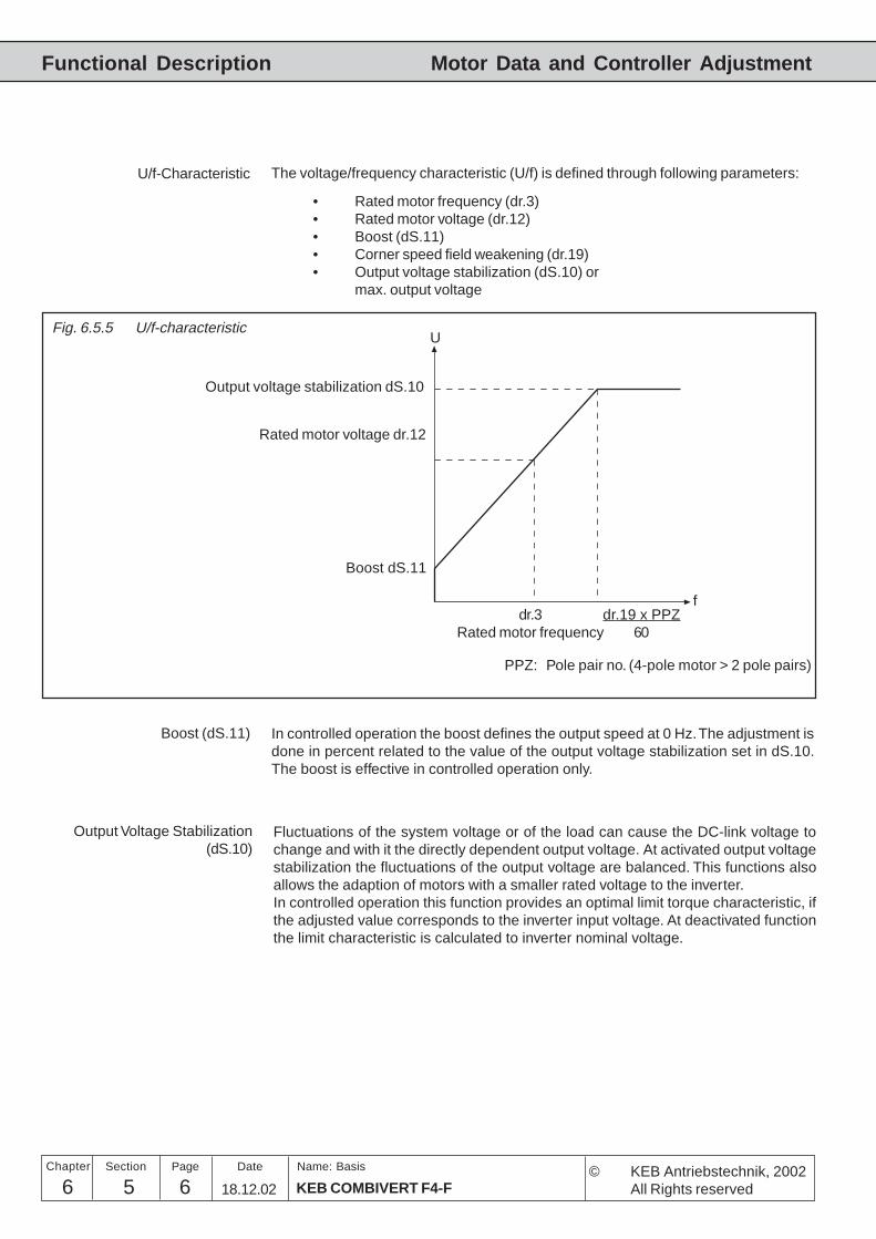
6 5 KEB COMBIVERT F4-F6Name: Basis
18.12.02
Chapter Section Page Date © KEB Antriebstechnik, 2002All Rights reserved
Functional Description Motor Data and Controller Adjustment
Boost (dS.11) In controlled operation the boost defines the output speed at 0 Hz. The adjustment isdone in percent related to the value of the output voltage stabilization set in dS.10.The boost is effective in controlled operation only.
Output Voltage Stabilization(dS.10)
Fluctuations of the system voltage or of the load can cause the DC-link voltage tochange and with it the directly dependent output voltage. At activated output voltagestabilization the fluctuations of the output voltage are balanced. This functions alsoallows the adaption of motors with a smaller rated voltage to the inverter.In controlled operation this function provides an optimal limit torque characteristic, ifthe adjusted value corresponds to the inverter input voltage. At deactivated functionthe limit characteristic is calculated to inverter nominal voltage.
U
f
Fig. 6.5.5 U/f-characteristic
The voltage/frequency characteristic (U/f) is defined through following parameters:
• Rated motor frequency (dr.3)• Rated motor voltage (dr.12)• Boost (dS.11)• Corner speed field weakening (dr.19)• Output voltage stabilization (dS.10) or
max. output voltage
U/f-Characteristic
Output voltage stabilization dS.10
Rated motor voltage dr.12
Boost dS.11
dr.3Rated motor frequency
dr.19 x PPZ60
PPZ: Pole pair no. (4-pole motor > 2 pole pairs)

76 5 7KEB COMBIVERT F4-F
Name: Basis
18.12.02
6
Section PageDate© KEB Antriebstechnik, 2002All Rights reserved
Chapter
Functional DescriptionMotor Data and Controller Adjustment
250 V
CP.17 = 230 V
190 V
CP.5 = 50 Hzf
UN/UAFig. 6.5.8.a Output voltage stabilization
UA bei UN = 250V stabilized
UA bei UN = 190V non-stabilized
UA bei UN = 190V stabilized
UA bei UN = 250V non-stabilized
UN = system voltageUA = output voltage
Fig. 6.5.8.b Example: Deceleration of a drive for high-inertia load from 80 Hz (controlled)
with output voltagestabilization
without output voltagestabilization
Load
Motor voltage
Actual speed
DC-link voltage
Load
Motor voltage
Actual speed
DC-link voltage
dS.10 = 230V
dr.3 = 50Hz
dS.10 = 1...500 V501 = off (default)
Example: dS.10 = 230Vno boost adjusted
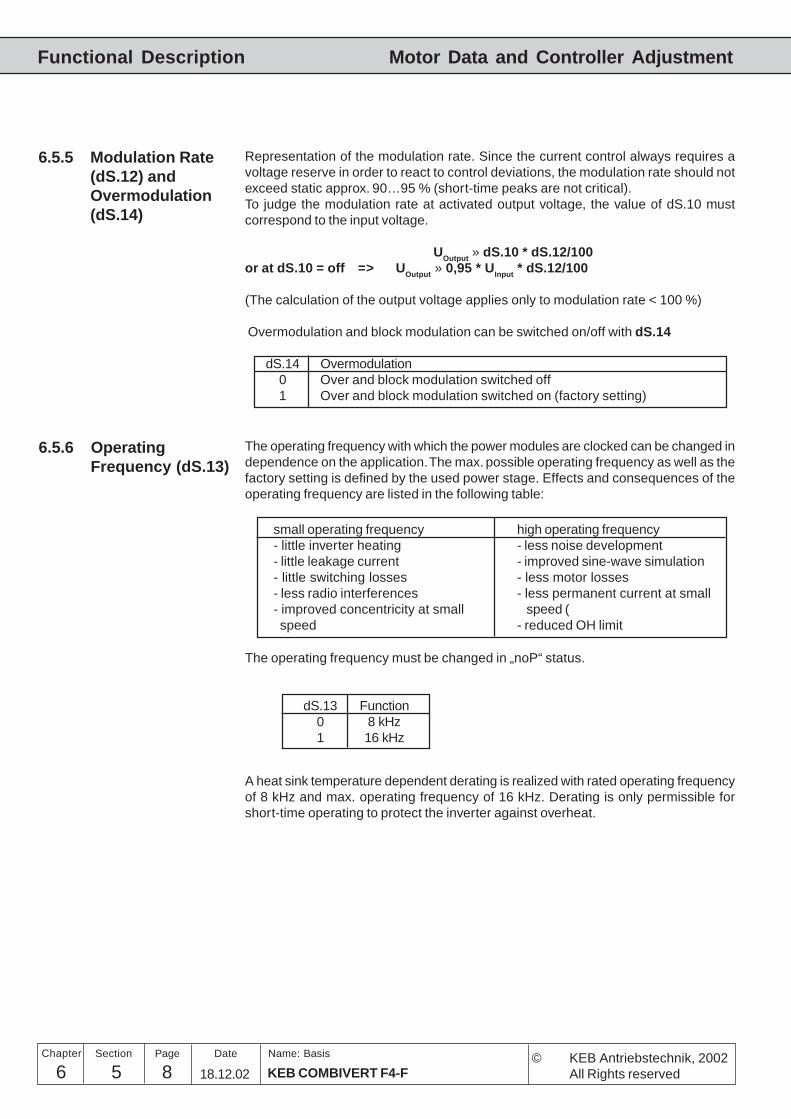
6 5 KEB COMBIVERT F4-F8Name: Basis
18.12.02
Chapter Section Page Date © KEB Antriebstechnik, 2002All Rights reserved
Functional Description Motor Data and Controller Adjustment
6.5.5 Modulation Rate(dS.12) andOvermodulation(dS.14)
6.5.6 OperatingFrequency (dS.13)
The operating frequency with which the power modules are clocked can be changed independence on the application. The max. possible operating frequency as well as thefactory setting is defined by the used power stage. Effects and consequences of theoperating frequency are listed in the following table:
small operating frequency- little inverter heating- little leakage current- little switching losses- less radio interferences- improved concentricity at small speed
high operating frequency- less noise development- improved sine-wave simulation- less motor losses- less permanent current at small
speed (- reduced OH limit
Representation of the modulation rate. Since the current control always requires avoltage reserve in order to react to control deviations, the modulation rate should notexceed static approx. 90…95 % (short-time peaks are not critical).To judge the modulation rate at activated output voltage, the value of dS.10 mustcorrespond to the input voltage.
UOutput » dS.10 * dS.12/100or at dS.10 = off => UOutput » 0,95 * UInput * dS.12/100
(The calculation of the output voltage applies only to modulation rate < 100 %)
Overmodulation and block modulation can be switched on/off with dS.14
dS.14 Overmodulation0 Over and block modulation switched off1 Over and block modulation switched on (factory setting)
The operating frequency must be changed in „noP“ status.
dS.13 Function0 8 kHz1 16 kHz
A heat sink temperature dependent derating is realized with rated operating frequencyof 8 kHz and max. operating frequency of 16 kHz. Derating is only permissible forshort-time operating to protect the inverter against overheat.

96 5 9KEB COMBIVERT F4-F
Name: Basis
18.12.02
6
Section PageDate© KEB Antriebstechnik, 2002All Rights reserved
Chapter
Functional DescriptionMotor Data and Controller Adjustment
6.5.7 Controller Structure
PG
ASM3~
Usd
Usq+
+
Umax
U
V
W
d
q
6.5.11 Controller structure
nset
+
nactual -
Speed controller
Current control
Isq-controller(PI-controler)
Voltageprecontrol
Isd-controller(PI-controler)
Flow loweringcalculation
Flowcorrection
Trans-formation
Powercircuit
Transformationangular
Transformation
Speed Rotor positionSpeedcalculation
Flow controller
Flow calculationset actual
Isdactual
Isdset
Isqset +
Isqactual -
IU
IV
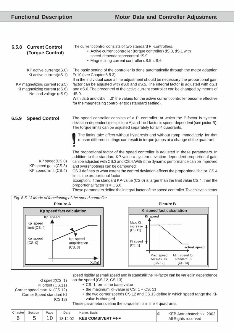
6 5 KEB COMBIVERT F4-F10Name: Basis
18.12.02
Chapter Section Page Date © KEB Antriebstechnik, 2002All Rights reserved
Functional Description Motor Data and Controller Adjustment
6.5.9 Speed Control The speed controller consists of a PI-controller, at which the P-factor is system-deviation-dependent (see picture A) and the I-factor is speed-dependent (see pictur B).The torque limits can be adjusted separately for all 4 quadrants.
The limits take effect without hysteresis and without ramp immediately, for thatreason different settings can result in torque jumps at a change of the quadrant.
The proportional factor of the speed controller is adjusted in these parameters. Inaddition to the standard KP-value a system-deviation-dependent proportional gaincan be adjusted with CS.3 and CS.4. With it the dynamic performance can be improvedand overshootings can be dampened.CS.3 defines to what extent the control deviation effects the proportional factor. CS.4limits the proportional factor.Exception: If the standard KP-value (CS.0) is larger than the limit value CS.4, then theproportional factor is = CS.0.These parameters define the integral factor of the speed controller. To achieve a better
speed rigidity at small speed and in standstill the KI-factor can be varied in dependenceon the speed (CS.12, CS.13).
• CS. 1 forms the base value• the maximum KI-value is CS. 1 + CS. 11• the two corner speeds CS.12 and CS.13 define in which speed range the KI-
value is changedThese parameters define the torque limits in the 4 quadrants.
KP speed(CS.0)KP speed gain (CS.3)KP speed limit (CS.4)
KI speed(CS. 1)KI offset (CS.11)
Corner speed max. KI (CS.12)Corner Speed standard KI
(CS.13)
Fig. 6.5.13 Mode of functioning of the speed controller
Picture A Picture B
Kp speedlimit [CS. 4]
Kp speed[CS. 0]
Kp speedamplification[CS. 3]
Kp speed
Xd(n)
Kp speed fact calculation Ki speed fact calculation
Max. Kiincrease[CS.11]
Ki speed[CS. 1]
Max. speedfor max. Ki
[CS.12]
Min. speed forstandard Ki
[CS.13]
actual speed
Ki speed
6.5.8 Current Control(Torque Control)
The current control consists of two standard PI-controllers.• Active current controller (torque controller) dS.0, dS.1 with
speed-dependent precontrol dS.9• Magnetizing current controller dS.5, dS.6
The basic setting of the controller is done automatically through the motor adaptionFr.10 (see Chapter 6.5.3).If in the individual case a fine adjustment should be necessary the proportional gainfactor can be adjusted with dS.0 and dS.5. The integral factor is adjusted with dS.1and dS.6. The precontrol of the active current controller can be changed by means ofdS.9.With ds.5 and dS.6 = „0“ the values for the active current controller become effectivefor the magnetizing controller too (standard setting).
KP active current(dS.0)KI active current(dS.1)
KP magnetizing current (dS.5)KI magnetizing current (dS.6)
No-load voltage (dS.9)
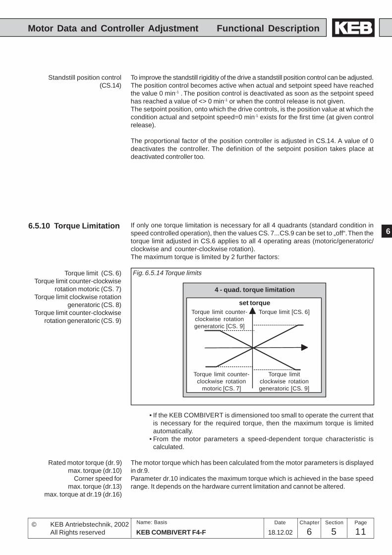
116 5 11KEB COMBIVERT F4-F
Name: Basis
18.12.02
6
Section PageDate© KEB Antriebstechnik, 2002All Rights reserved
Chapter
Functional DescriptionMotor Data and Controller Adjustment
If only one torque limitation is necessary for all 4 quadrants (standard condition inspeed controlled operation), then the values CS. 7...CS.9 can be set to „off“. Then thetorque limit adjusted in CS.6 applies to all 4 operating areas (motoric/generatoric/clockwise and counter-clockwise rotation).The maximum torque is limited by 2 further factors:
• If the KEB COMBIVERT is dimensioned too small to operate the current thatis necessary for the required torque, then the maximum torque is limitedautomatically.
• From the motor parameters a speed-dependent torque characteristic iscalculated.
The motor torque which has been calculated from the motor parameters is displayedin dr.9.Parameter dr.10 indicates the maximum torque which is achieved in the base speedrange. It depends on the hardware current limitation and cannot be altered.
Torque limit (CS. 6)Torque limit counter-clockwise
rotation motoric (CS. 7)Torque limit clockwise rotation
generatoric (CS. 8)Torque limit counter-clockwise
rotation generatoric (CS. 9)
Fig. 6.5.14 Torque limits
6.5.10 Torque Limitation
Rated motor torque (dr. 9)max. torque (dr.10)
Corner speed formax. torque (dr.13)
max. torque at dr.19 (dr.16)
Torque limit counter-clockwise rotationgeneratoric [CS. 9]
set torqueTorque limit [CS. 6]
Torque limit counter-clockwise rotation
motoric [CS. 7]
Torque limitclockwise rotationgeneratoric [CS. 9]
4 - quad. torque limitation
To improve the standstill rigiditiy of the drive a standstill position control can be adjusted.The position control becomes active when actual and setpoint speed have reachedthe value 0 min-1 . The position control is deactivated as soon as the setpoint speedhas reached a value of <> 0 min-1 or when the control release is not given.The setpoint position, onto which the drive controls, is the position value at which thecondition actual and setpoint speed=0 min-1 exists for the first time (at given controlrelease).
The proportional factor of the position controller is adjusted in CS.14. A value of 0deactivates the controller. The definition of the setpoint position takes place atdeactivated controller too.
Standstill position control(CS.14)
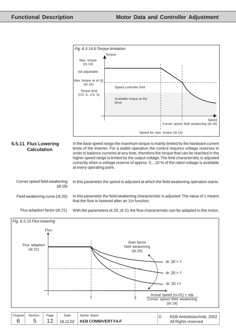
6 5 KEB COMBIVERT F4-F12Name: Basis
18.12.02
Chapter Section Page Date © KEB Antriebstechnik, 2002All Rights reserved
Functional Description Motor Data and Controller Adjustment
In the base speed range the maximum torque is mainly limited by the hardware currentlimits of the inverter. For a stable operation the control requires voltage reserves inorder to balance currents at any time, therefore the torque that can be reached in thehigher speed range is limited by the output voltage. The limit characteristic is adjustedcorrectly when a voltage reserve of approx. 5…10 % of the rated voltage is availableat every operating point.
In this parameter the speed is adjusted at which the field weakening operation starts.
In this parameter the field weakening characteristic is adjusted. The value of 1 meansthat the flow is lowered after an 1/n function.
With the parameters dr.20, dr.21 the flow characteristic can be adapted to the motor.
Corner speed field weakening(dr.19)
Field weakening curve (dr.20)
Flux adaption factor (dr.21)
Fig. 6.5.15 Flux lowering
Flux
Flux adaption(dr.21)
Gain factorfield weakening
(dr.20)
Actual speed (ru.01) + slipCorner speed field weakening
(dr.19)
6.5.11 Flux LoweringCalculation
Fig. 6.5.14.b Torque limitationTorque
Max. torque(dr.10)
not adjustable
Max. torque at dr.19(dr.16)
Torque limit(CS. 6...CS. 9)
Speed controller limit
Available torque at thedrive
Corner speed field weakening (dr.19)
Speed for max. torque (dr.13)
Speed
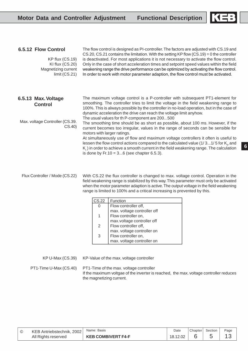
136 5 13KEB COMBIVERT F4-F
Name: Basis
18.12.02
6
Section PageDate© KEB Antriebstechnik, 2002All Rights reserved
Chapter
Functional DescriptionMotor Data and Controller Adjustment
KP flux (CS.19)KI flux (CS.20)
Magnetizing currentlimit (CS.21)
The flow control is designed as PI-controller. The factors are adjusted with CS.19 andCS.20, CS.21 contains the limitation. With the setting KP flow (CS.19) = 0 the controlleris deactivated. For most applications it is not necessary to activate the flow control.Only in the case of short acceleration times and setpoint speed values within the fieldweakening range the drive performance can be optimized by activating the flow control.In order to work with motor parameter adaption, the flow control must be activated.
6.5.12 Flow Control
Flux Controller / Mode (CS.22) With CS.22 the flux controller is changed to max. voltage control. Operation in thefield weakening range is stabilized by this way. This parameter must only be activatedwhen the motor parameter adaption is active. The output voltage in the field weakeningrange is limited to 100% and a critical increasing is prevented by this.
CS.22 Function0 Flow controller off,
max. voltage controller off1 Flow controller on,
max.voltage controller off2 Flow controller off,
max. voltage controller on3 Flow controller on,
max. voltage controller on
KP U-Max (CS.39)
PT1-Time U-Max (CS.40)
KP-Value of the max. voltage controller
PT1-Time of the max. voltage controllerIf the maximum voltgae of the inverter is reached, the max. voltage controller reducesthe magnetizing current.
6.5.13 Max. VoltageControl
The maximum voltage control is a P-controller with subsequent PT1-element forsmoothing. The controller tries to limit the voltage in the field weakening range to100%. This is always possible by the controller in no-load operation, but in the case ofdynamic acceleration the drive can reach the voltage limit anyhow.The usual values for th P-component are 200...500The smoothing time should be as short as possible, about 100 ms. However, if thecurrent becomes too irregular, values in the range of seconds can be sensible formotors with larger ratings.At simultaneously use of flow and maximum voltage controllers it often is useful tolessen the flow control actions compared to the calculated value (1/ 3...1/ 5 for KP andKI ) in order to achieve a smooth current in the field weakening range. The calculationis done by Fr.10 = 3...6 (see chapter 6.5.3).
Max. voltage Controller (CS.39.CS.40)
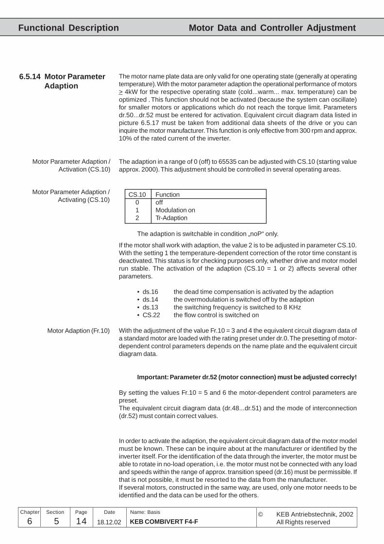
6 5 KEB COMBIVERT F4-F14Name: Basis
18.12.02
Chapter Section Page Date © KEB Antriebstechnik, 2002All Rights reserved
Functional Description Motor Data and Controller Adjustment
Motor Parameter Adaption /Activation (CS.10)
The motor name plate data are only valid for one operating state (generally at operatingtemperature). With the motor parameter adaption the operational performance of motors> 4kW for the respective operating state (cold...warm... max. temperature) can beoptimized . This function should not be activated (because the system can oscillate)for smaller motors or applications which do not reach the torque limit. Parametersdr.50...dr.52 must be entered for activation. Equivalent circuit diagram data listed inpicture 6.5.17 must be taken from additional data sheets of the drive or you caninquire the motor manufacturer. This function is only effective from 300 rpm and approx.10% of the rated current of the inverter.
The adaption in a range of 0 (off) to 65535 can be adjusted with CS.10 (starting valueapprox. 2000). This adjustment should be controlled in several operating areas.
6.5.14 Motor ParameterAdaption
Motor Parameter Adaption /Activating (CS.10)
CS.10 Function0 off1 Modulation on2 Tr-Adaption
In order to activate the adaption, the equivalent circuit diagram data of the motor modelmust be known. These can be inquire about at the manufacturer or identified by theinverter itself. For the identification of the data through the inverter, the motor must beable to rotate in no-load operation, i.e. the motor must not be connected with any loadand speeds within the range of approx. transition speed (dr.16) must be permissible. Ifthat is not possible, it must be resorted to the data from the manufacturer.If several motors, constructed in the same way, are used, only one motor needs to beidentified and the data can be used for the others.
If the motor shall work with adaption, the value 2 is to be adjusted in parameter CS.10.With the setting 1 the temperature-dependent correction of the rotor time constant isdeactivated. This status is for checking purposes only, whether drive and motor modelrun stable. The activation of the adaption (CS.10 = 1 or 2) affects several otherparameters.
• ds.16 the dead time compensation is activated by the adaption• ds.14 the overmodulation is switched off by the adaption• ds.13 the switching frequency is switched to 8 KHz• CS.22 the flow control is switched on
With the adjustment of the value Fr.10 = 3 and 4 the equivalent circuit diagram data ofa standard motor are loaded with the rating preset under dr.0. The presetting of motor-dependent control parameters depends on the name plate and the equivalent circuitdiagram data.
Important: Parameter dr.52 (motor connection) must be adjusted correcly!
By setting the values Fr.10 = 5 and 6 the motor-dependent control parameters arepreset.The equivalent circuit diagram data (dr.48...dr.51) and the mode of interconnection(dr.52) must contain correct values.
Motor Adaption (Fr.10)
The adaption is switchable in condition „noP“ only.

156 5 15KEB COMBIVERT F4-F
Name: Basis
18.12.02
6
Section PageDate© KEB Antriebstechnik, 2002All Rights reserved
Chapter
Functional DescriptionMotor Data and Controller Adjustment
Data from the manufacturer Following proceeding is recommended at the activation of the adaption, if the equivalentcircuit diagram data are made available from the manufacturer of the motor (its impera-tive to observe the sequence!!).
1.) Enter name plate data as usual.
2.) Write the value 2 or 3 to Fr.10 . The function is the same as with the setting ofvalue 1 or 2 (see page 6.5.4), in addition to it the equivalent circuit diagram dataof a standard motor with the appropriate rating (d.r.0) are loaded.
3.) Enter the exact motor data of the manufacturer in dr.48...dr.51.
4.) Finally write the value 5 or 6 to Fr.10. Thus the controllers are adapted to thenew motor data.
The error message „Data invalid“ during input over COMBIVIS or „nco“ during inputover keyboard indicates that an error occured at the calculation of the internal modelsize. This is probably due to the nput of wrong equivalent circuit diagram data.
Identification through the inverter
Procedure
There are two kinds of indentification by the inverter. A complete identification (ds.18 =200) and the identification of the resistance (ds.18 = 440). In the case of the resistanceidentification the motor stands still, but does not generate any torque. The resistanceidentification is to be recommended only, if the motor is allowed to rotate and approx.values for the inductances are known. Otherwise the complete identification is necessaryfor the adaption.
The motor must not be connected with any load. The motor must be able torotate with a speed of approx. transition speed. During the indentification theinverter generates test signals that can cause motor noises (pinging).
1.) The control release must be open (Status „nOP“)
2.) Enter the data of the name plate und start up the drive in standard operation(CS.10 = ), i.e. check speed feedback.Switch over the drive into controlled operation (CS.23 = 1) and ensure, that thespeed controller does not swing and the drive runs.
3.) Fr.10 = 3 or 4Function same as with setting of value 1 or 2 (see page 6.5.4), additionally theequivalent circuit diagram data of a standard motor with the corresponding rating(dr.0) are loaded.In so doing the adjustment of the current control is adapted.It is absolutely necessary to adjust the correct motor wiring in dr.52 !
4.) Ensure that following adjustments are programmed in the inverter:- CS.23 = 1, controlled operation- long acceleration and deceleration times, depending on the rating of the
inverter between 5s and 30 s- with digital speed setting or by terminal strips the rotation direction must
be given before starting the identification
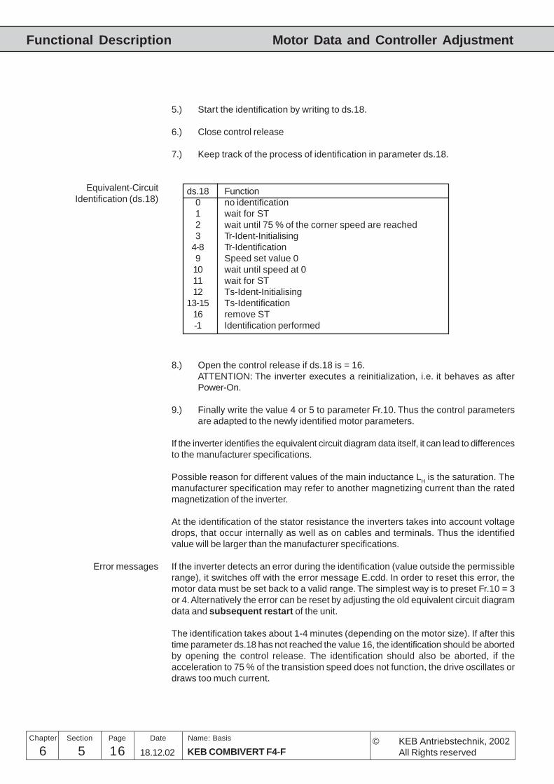
6 5 KEB COMBIVERT F4-F16Name: Basis
18.12.02
Chapter Section Page Date © KEB Antriebstechnik, 2002All Rights reserved
Functional Description Motor Data and Controller Adjustment
8.) Open the control release if ds.18 is = 16.ATTENTION: The inverter executes a reinitialization, i.e. it behaves as afterPower-On.
9.) Finally write the value 4 or 5 to parameter Fr.10. Thus the control parametersare adapted to the newly identified motor parameters.
If the inverter identifies the equivalent circuit diagram data itself, it can lead to differencesto the manufacturer specifications.
Possible reason for different values of the main inductance LH is the saturation. Themanufacturer specification may refer to another magnetizing current than the ratedmagnetization of the inverter.
At the identification of the stator resistance the inverters takes into account voltagedrops, that occur internally as well as on cables and terminals. Thus the identifiedvalue will be larger than the manufacturer specifications.
If the inverter detects an error during the identification (value outside the permissiblerange), it switches off with the error message E.cdd. In order to reset this error, themotor data must be set back to a valid range. The simplest way is to preset Fr.10 = 3or 4. Alternatively the error can be reset by adjusting the old equivalent circuit diagramdata and subsequent restart of the unit.
The identification takes about 1-4 minutes (depending on the motor size). If after thistime parameter ds.18 has not reached the value 16, the identification should be abortedby opening the control release. The identification should also be aborted, if theacceleration to 75 % of the transistion speed does not function, the drive oscillates ordraws too much current.
Error messages
ds.18 Function0 no identification1 wait for ST2 wait until 75 % of the corner speed are reached3 Tr-Ident-Initialising
4-8 Tr-Identification9 Speed set value 010 wait until speed at 011 wait for ST12 Ts-Ident-Initialising
13-15 Ts-Identification16 remove ST-1 Identification performed
Equivalent-CircuitIdentification (ds.18)
5.) Start the identification by writing to ds.18.
6.) Close control release
7.) Keep track of the process of identification in parameter ds.18.
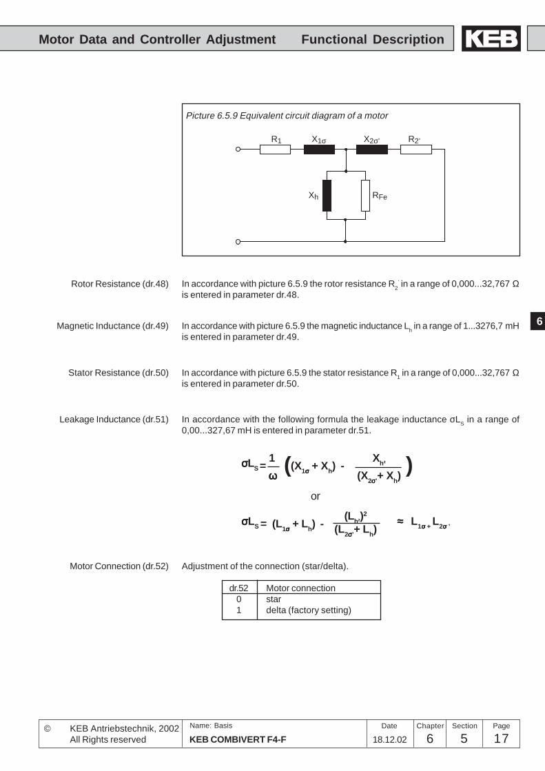
176 5 17KEB COMBIVERT F4-F
Name: Basis
18.12.02
6
Section PageDate© KEB Antriebstechnik, 2002All Rights reserved
Chapter
Functional DescriptionMotor Data and Controller Adjustment
R1 X1σ X2σ’ R2’
Xh RFe
σσσσσLS =1 ((X1σσσσσ + Xh) -
Xh² )ωωωωω (X2σσσσσ’+ Xh)
σσσσσLS = (L1σσσσσ + Lh) -
(Lh²)2
≈≈≈≈≈ L1σσσσσ + L2σσσσσ ’(L2σσσσσ’+ Lh)
Stator Resistance (dr.50)
Picture 6.5.9 Equivalent circuit diagram of a motor
In accordance with picture 6.5.9 the stator resistance R1 in a range of 0,000...32,767 Ω
is entered in parameter dr.50.
Leakage Inductance (dr.51) In accordance with the following formula the leakage inductance σLS in a range of
0,00...327,67 mH is entered in parameter dr.51.
or
Magnetic Inductance (dr.49)
Rotor Resistance (dr.48)
In accordance with picture 6.5.9 the magnetic inductance Lh in a range of 1...3276,7 mH
is entered in parameter dr.49.
In accordance with picture 6.5.9 the rotor resistance R2
’ in a range of 0,000...32,767 Ωis entered in parameter dr.48.
Motor Connection (dr.52) Adjustment of the connection (star/delta).
dr.52 Motor connection0 star1 delta (factory setting)
6 5 KEB COMBIVERT F4-F18Name: Basis
18.12.02
Chapter Section Page Date © KEB Antriebstechnik, 2002All Rights reserved
Functional Description Motor Data and Controller Adjustment
Adaption factor (dS.15) Display of the adaption intervention.
Range of values: off (adaption off)0,1% ... 100,0% (no intervention)
At ds.15 = 0 : off the adaption is not active.
Alternative Terms The resistors R1 and R2 may be termed as RS and R
R, too.
To be taken into account at the evaluation of the manufacturer data:
The motor model requires the phase resistances and inductances. However, in partonly linked values (also called conductor-conductor-values or R
UV and L
UV ) are specified
by the manufacturer.
Conversions
Star connection: Phase values = linked values / 2
Delta connection: Phase values = linked values x 1,5
Instead of the inductances (L) also reactances (X) can be spedified.
Delay time flux build-up (ds.17) If ds.17 is activated, the setpoint value for speed and torque is maintained on 0until the flux (the magnetic field) is build up in the motor.
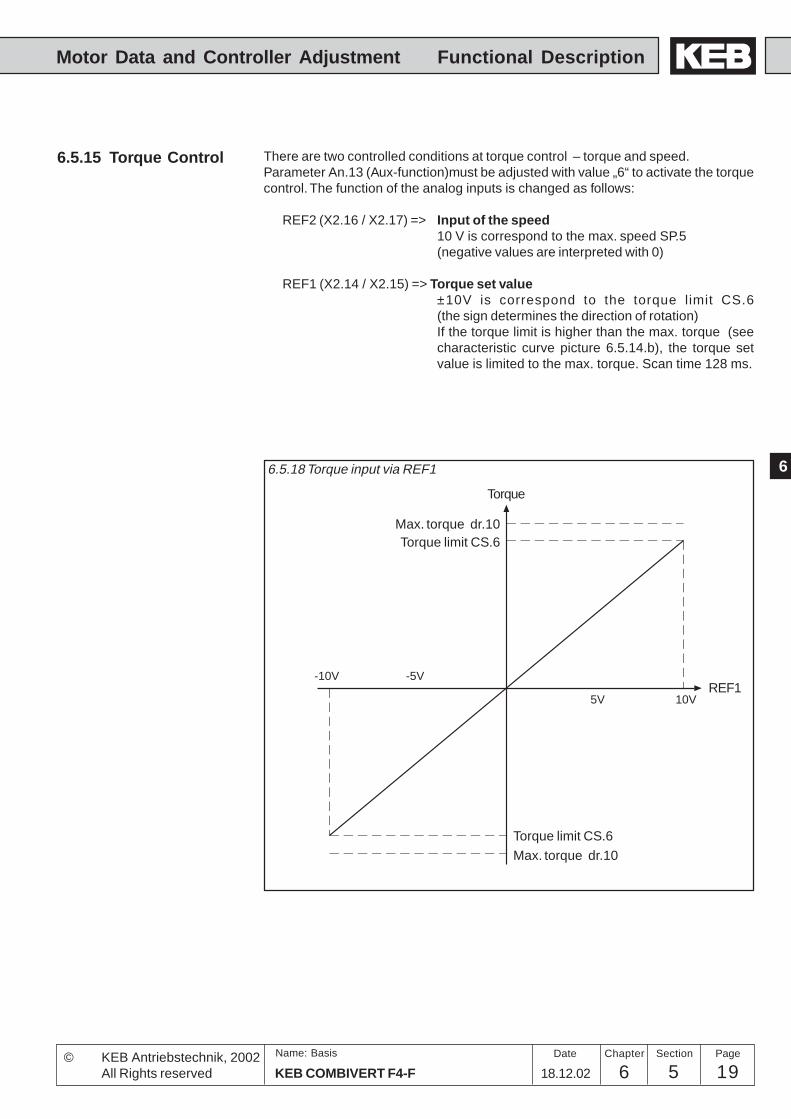
196 5 19KEB COMBIVERT F4-F
Name: Basis
18.12.02
6
Section PageDate© KEB Antriebstechnik, 2002All Rights reserved
Chapter
Functional DescriptionMotor Data and Controller Adjustment
There are two controlled conditions at torque control – torque and speed.Parameter An.13 (Aux-function)must be adjusted with value „6“ to activate the torquecontrol. The function of the analog inputs is changed as follows:
REF2 (X2.16 / X2.17) => Input of the speed10 V is correspond to the max. speed SP.5(negative values are interpreted with 0)
REF1 (X2.14 / X2.15) => Torque set value±10V is correspond to the torque limit CS.6(the sign determines the direction of rotation)If the torque limit is higher than the max. torque (seecharacteristic curve picture 6.5.14.b), the torque setvalue is limited to the max. torque. Scan time 128 ms.
-10V
10V
-5V
5V
Torque
Max. torque dr.10Torque limit CS.6
REF1
Max. torque dr.10
Torque limit CS.6
6.5.18 Torque input via REF1
6.5.15 Torque Control
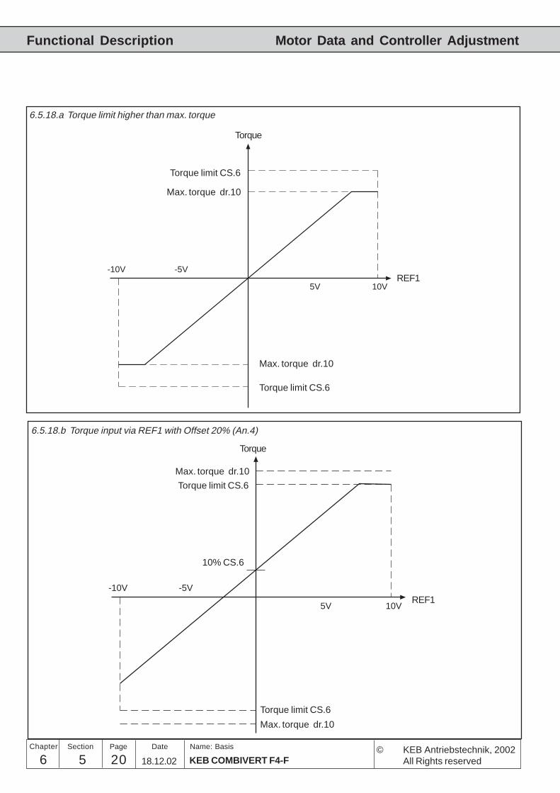
6 5 KEB COMBIVERT F4-F20Name: Basis
18.12.02
Chapter Section Page Date © KEB Antriebstechnik, 2002All Rights reserved
Functional Description Motor Data and Controller Adjustment
-10V
10V
-5V
5V
6.5.18.b Torque input via REF1 with Offset 20% (An.4)
Torque
Torque limit CS.6
REF1
Max. torque dr.10
Torque limit CS.6
10% CS.6
Max. torque dr.10
-10V
10V
-5V
5V
6.5.18.a Torque limit higher than max. torque
Torque
Torque limit CS.6
REF1
Max. torque dr.10
Torque limit CS.6
Max. torque dr.10
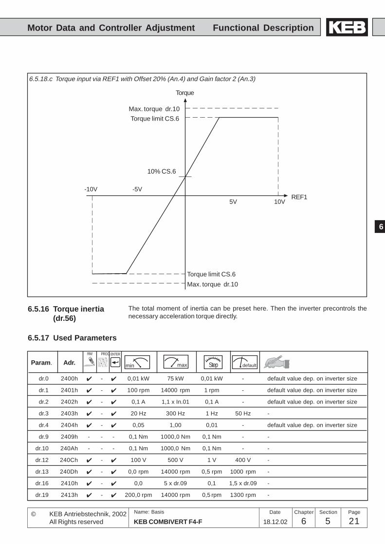
216 5 21KEB COMBIVERT F4-F
Name: Basis
18.12.02
6
Section PageDate© KEB Antriebstechnik, 2002All Rights reserved
Chapter
Functional DescriptionMotor Data and Controller Adjustment
max
6.5.17 Used Parameters
dr.0 2400h - 0,01 kW 75 kW 0,01 kW - default value dep. on inverter size
dr.1 2401h - 100 rpm 14000 rpm 1 rpm - default value dep. on inverter size
dr.2 2402h - 0,1 A 1,1 x In.01 0,1 A - default value dep. on inverter size
dr.3 2403h - 20 Hz 300 Hz 1 Hz 50 Hz -
dr.4 2404h - 0,05 1,00 0,01 - default value dep. on inverter size
dr.9 2409h - - - 0,1 Nm 1000,0 Nm 0,1 Nm - -
dr.10 240Ah - - - 0,1 Nm 1000,0 Nm 0,1 Nm - -
dr.12 240Ch - 100 V 500 V 1 V 400 V -
dr.13 240Dh - 0,0 rpm 14000 rpm 0,5 rpm 1000 rpm -
dr.16 2410h - 0,0 5 x dr.09 0,1 1,5 x dr.09 -
dr.19 2413h - 200,0 rpm 14000 rpm 0,5 rpm 1300 rpm -
Param. Adr. min default
ENTERPROG.R/W
Step
-10V
10V
-5V
5V
6.5.18.c Torque input via REF1 with Offset 20% (An.4) and Gain factor 2 (An.3)
Torque limit CS.6
REF1
Max. torque dr.10
Torque limit CS.6
10% CS.6
Max. torque dr.10
Torque
The total moment of inertia can be preset here. Then the inverter precontrols thenecessary acceleration torque directly.
6.5.16 Torque inertia(dr.56)
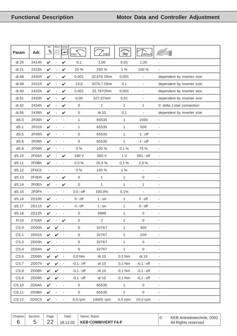
6 5 KEB COMBIVERT F4-F22Name: Basis
18.12.02
Chapter Section Page Date © KEB Antriebstechnik, 2002All Rights reserved
Functional Description Motor Data and Controller Adjustment
Param. Adr. min max default
ENTERPROG.R/W
Step
dr.20 2414h - 0,1 2,00 0,01 1,20 -
dr.21 2415h - 25 % 250 % 1 % 100 % -
dr.48 2430h - 0,001 32,676 Ohm 0,001 - dependent by inverter size
dr.49 2431h - 10,0 3276,7 Ohm 0,1 - dependent by inverter size
dr.50 2432h - 0,001 32,767Ohm 0,001 - dependent by inverter size
dr.51 2433h - 0,00 327,67mH 0,01 - dependent by inverter size
dr.52 2434h - 0 1 1 1 0: delta 1:star connection
dr.56 2438h - 0 dr.10 0,1 - dependent by inverter size
dS.0 2F00h - - 1 65535 1 1500 -
dS.1 2F01h - - 1 65535 1 500 -
dS.5 2F05h - - 0 65535 1 -1 : off -
dS.6 2F06h - - 0 65535 1 -1 : off -
dS.9 2F09h - - 0 % 100 % 0,1 % 75 % -
dS.10 2F0Ah - 180 V 500 V 1 V 501 : off -
dS.11 2F0Bh - - 0,0 % 25,5 % 0,1 % 2,0 % -
dS.12 2F0Ch - - - 0 % 100 % 1 % - -
dS.13 2F0Dh - 0 1 1 0 -
dS.14 2F0Eh - 0 1 1 1 -
dS.15 2F0Fh - - - 0,0 : off 100,0% 0,1% - -
dS.16 2D10h - - 0 : off 1 : on 1 0 : off -
dS.17 2D11h - - 0 : off 1 : on 1 0 : off -
dS.18 2D12h - - 0 9999 1 0 -
Fr.10 270Ah - 0 2 1 0 -
CS.0 2D00h - 0 32767 1 400 -
CS.1 2D01h - 0 32767 1 200 -
CS.3 2D03h - - 0 32767 1 0 -
CS.4 2D04h - - 0 32767 1 0 -
CS.6 2D06h - 0,0 Nm dr.10 0,1 Nm dr.10 -
CS.7 2D07h - -0,1 : off dr.10 0,1 Nm -0,1 : off -
CS.8 2D08h - -0,1 : off dr.10 0,1 Nm -0,1 : off -
CS.9 2D09h - -0,1 : off dr.10 0,1 Nm -0,1 : off -
CS.10 2D0Ah - - 0 65535 1 0 -
CS.11 2D0Bh - - 0 65535 1 0 -
CS.12 2D0Ch - - 0,0 rpm 14000 rpm 0,5 rpm 10,0 rpm -
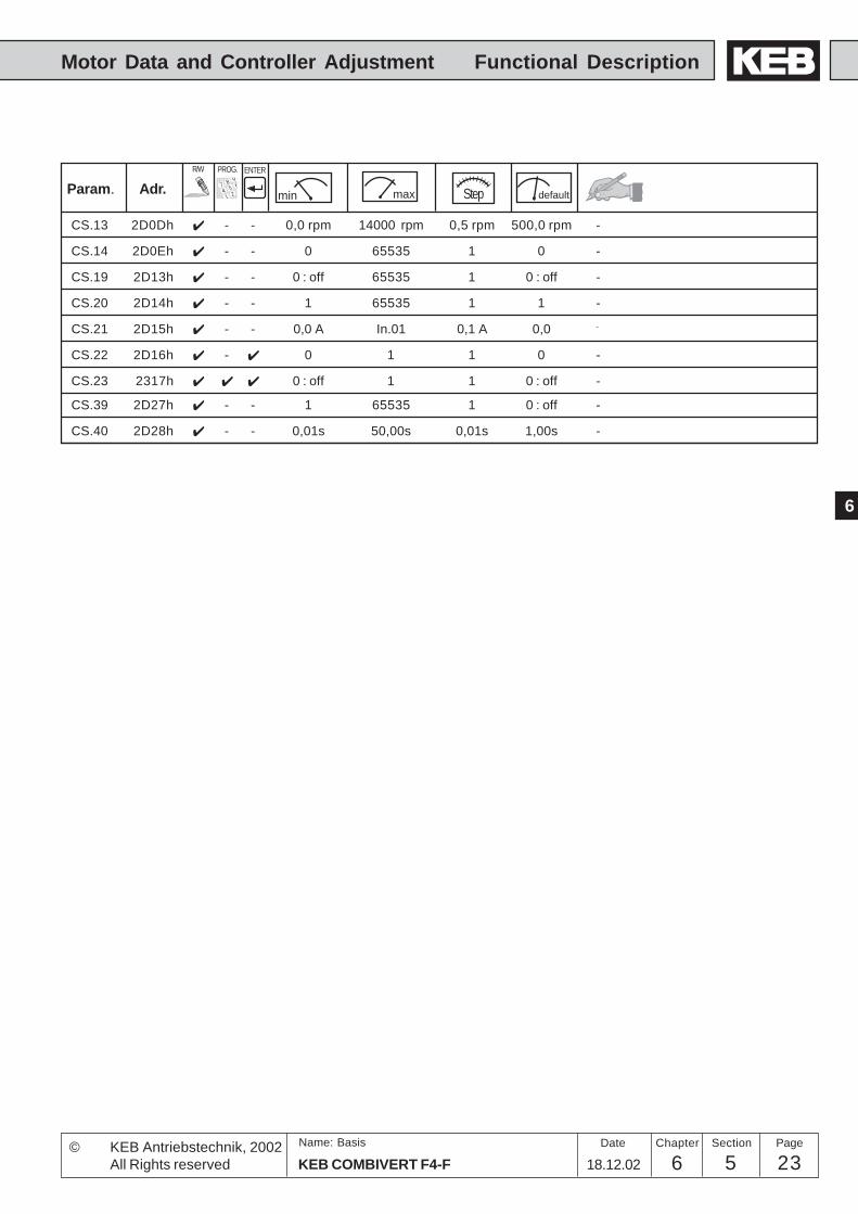
236 5 23KEB COMBIVERT F4-F
Name: Basis
18.12.02
6
Section PageDate© KEB Antriebstechnik, 2002All Rights reserved
Chapter
Functional DescriptionMotor Data and Controller Adjustment
Param. Adr. min max default
ENTERPROG.R/W
Step
CS.13 2D0Dh - - 0,0 rpm 14000 rpm 0,5 rpm 500,0 rpm -
CS.14 2D0Eh - - 0 65535 1 0 -
CS.19 2D13h - - 0 : off 65535 1 0 : off -
CS.20 2D14h - - 1 65535 1 1 -
CS.21 2D15h - - 0,0 A In.01 0,1 A 0,0 -
CS.22 2D16h - 0 1 1 0 -
CS.23 2317h 0 : off 1 1 0 : off -
CS.39 2D27h - - 1 65535 1 0 : off -
CS.40 2D28h - - 0,01s 50,00s 0,01s 1,00s -

6 5 KEB COMBIVERT F4-F24Name: Basis
18.12.02
Chapter Section Page Date © KEB Antriebstechnik, 2002All Rights reserved
Functional Description Motor Data and Controller Adjustment
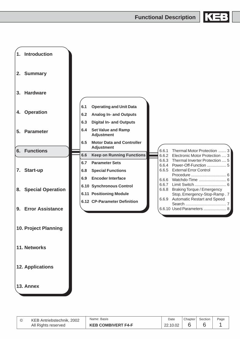
6 6 1KEB COMBIVERT F4-F
Name: Basis
22.10.02
Functional Description
Chapter Section PageDate© KEB Antriebstechnik, 2002All Rights reserved
1. Introduction
2. Summary
3. Hardware
4. Operation
5. Parameter
6. Functions
7. Start-up
8. Special Operation
9. Error Assistance
10. Project Planning
11. Networks
12. Applications
13. Annex
6.1 Operating and Unit Data
6.2 Analog In- and Outputs
6.3 Digital In- and Outputs
6.4 Set Value and RampAdjustment
6.5 Motor Data and ControllerAdjustment
6.6 Keep on Running Functions
6.7 Parameter Sets
6.8 Special Functions
6.9 Encoder Interface
6.10 Synchronous Control
6.11 Positioning Module
6.12 CP-Parameter Definition
6.6.1 Thermal Motor Protection ....... 36.6.2 Electronic Motor Protection .... 36.6.3 Thermal Inverter Protection .... 56.6.4 Power-Off-Function ................. 56.6.5 External Error Control
Procedure ............................... 66.6.6 Watchdo-Time ........................ 66.6.7 Limit Switch ............................ 66.6.8 Braking Torque / Emergency
Stop, Emergency-Stop-Ramp . 76.6.9 Automatic Restart and Speed
Search .................................... 76.6.10 Used Parameters .................... 8

6 6 KEB COMBIVERT F4-F2Name: Basis
22.10.02
Chapter Section Page Date © KEB Antriebstechnik, 2002All Rights reserved
Functional Description Keep on Running Functions
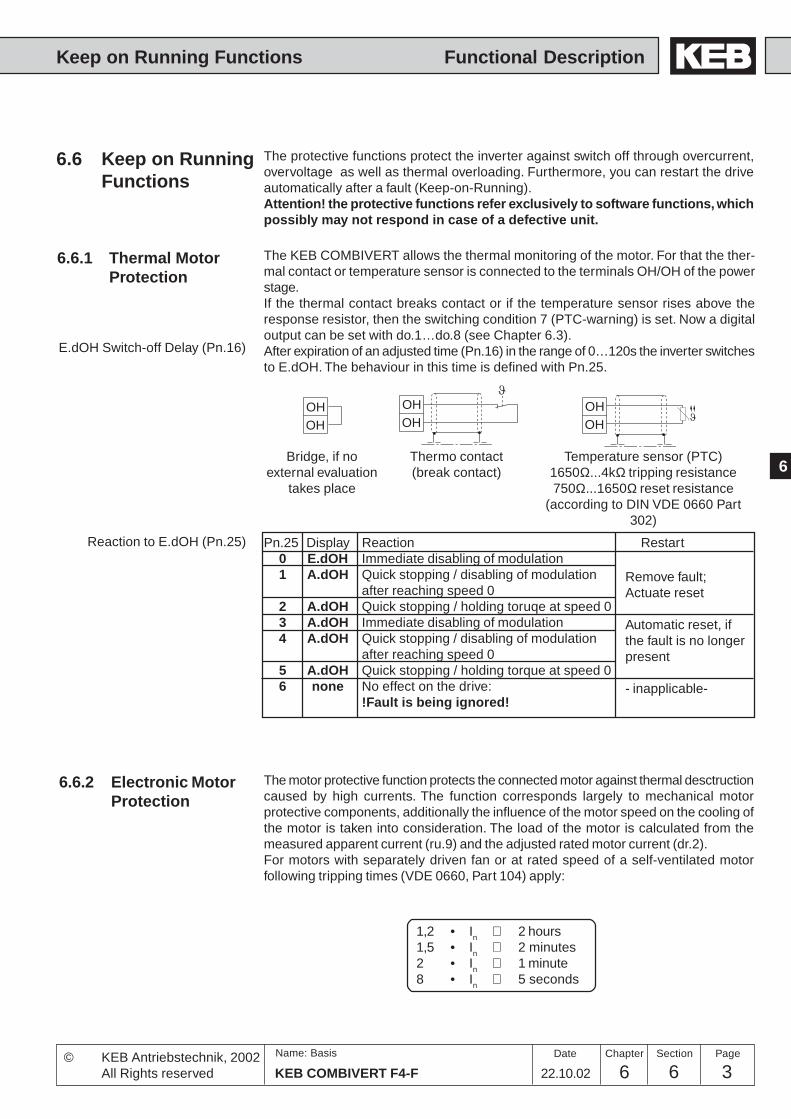
36 6 3KEB COMBIVERT F4-F
Name: Basis
22.10.02
6
Section PageDate© KEB Antriebstechnik, 2002All Rights reserved
Chapter
Functional DescriptionKeep on Running Functions
The KEB COMBIVERT allows the thermal monitoring of the motor. For that the ther-mal contact or temperature sensor is connected to the terminals OH/OH of the powerstage.If the thermal contact breaks contact or if the temperature sensor rises above theresponse resistor, then the switching condition 7 (PTC-warning) is set. Now a digitaloutput can be set with do.1…do.8 (see Chapter 6.3).After expiration of an adjusted time (Pn.16) in the range of 0…120s the inverter switchesto E.dOH. The behaviour in this time is defined with Pn.25.
Pn.25 Display Reaction Restart0 E.dOH Immediate disabling of modulation1 A.dOH Quick stopping / disabling of modulation
after reaching speed 02 A.dOH Quick stopping / holding toruqe at speed 03 A.dOH Immediate disabling of modulation4 A.dOH Quick stopping / disabling of modulation
after reaching speed 05 A.dOH Quick stopping / holding torque at speed 06 none No effect on the drive:
!Fault is being ignored!
OHOH
OHOH
OHOH
6.6 Keep on RunningFunctions
6.6.1 Thermal MotorProtection
The protective functions protect the inverter against switch off through overcurrent,overvoltage as well as thermal overloading. Furthermore, you can restart the driveautomatically after a fault (Keep-on-Running).Attention! the protective functions refer exclusively to software functions, whichpossibly may not respond in case of a defective unit.
E.dOH Switch-off Delay (Pn.16)
Remove fault;Actuate reset
Automatic reset, ifthe fault is no longerpresent
- inapplicable-
Reaction to E.dOH (Pn.25)
Bridge, if noexternal evaluation
takes place
Thermo contact(break contact)
Temperature sensor (PTC)1650Ω...4kΩ tripping resistance750Ω...1650Ω reset resistance
(according to DIN VDE 0660 Part302)
The motor protective function protects the connected motor against thermal desctructioncaused by high currents. The function corresponds largely to mechanical motorprotective components, additionally the influence of the motor speed on the cooling ofthe motor is taken into consideration. The load of the motor is calculated from themeasured apparent current (ru.9) and the adjusted rated motor current (dr.2).For motors with separately driven fan or at rated speed of a self-ventilated motorfollowing tripping times (VDE 0660, Part 104) apply:
1,2 • In ⇒ 2 hours1,5 • In ⇒ 2 minutes2 • In ⇒ 1 minute8 • In ⇒ 5 seconds
6.6.2 Electronic MotorProtection

6 6 KEB COMBIVERT F4-F4Name: Basis
22.10.02
Chapter Section Page Date © KEB Antriebstechnik, 2002All Rights reserved
Functional Description Keep on Running Functions
Pn.3 Electronic motor protection
0 no function
1 only warning, motor with separate fan
2 only warning, motor without separate fan
3 motor with separate fan (error E.OH2)
4 motor without separate fan (error E.OH2)
ru.9 Apparent current
dr.2 Rated motor current0.1…460.0 A
see Application manual Chapter 6.3.12 „Switching Conditions“do.1...do.8 „Value 36“
Error detection
Fig. 6.6.1 Principle of electronic motor protective function
50 100 150 200 400 600 800%
5 sec30 sec
1 min
2 min
30 min
60 min
120 min
120
n = 0 rpm
Tripping time
n ≥ Rated motor speed orforced-ventilated motor
Motor current
For self-ventilated motors the tripping timesdecrease with the speed of the motor (see picture).The motor protective function acts integrating, i.e.times with overload on the motor are added, timeswith underload are substracted. After triggering themotor protective function, the new tripping time isreduced to 1/4 of the specified value, if the motorhas not been operated for an appropriate time withunderload.
Fig 6.6.2 Tripping times of motor protective function
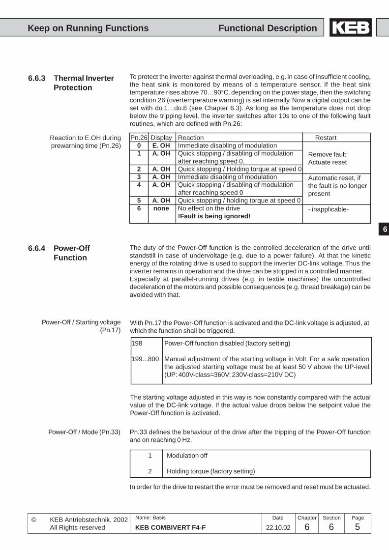
56 6 5KEB COMBIVERT F4-F
Name: Basis
22.10.02
6
Section PageDate© KEB Antriebstechnik, 2002All Rights reserved
Chapter
Functional DescriptionKeep on Running Functions
6.6.4 Power-OffFunction
The duty of the Power-Off function is the controlled deceleration of the drive untilstandstill in case of undervoltage (e.g. due to a power failure). At that the kineticenergy of the rotating drive is used to support the inverter DC-link voltage. Thus theinverter remains in operation and the drive can be stopped in a controlled manner.Especially at parallel-running drives (e.g. in textile machines) the uncontrolleddeceleration of the motors and possible consequences (e.g. thread breakage) can beavoided with that.
With Pn.17 the Power-Off function is activated and the DC-link voltage is adjusted, atwhich the function shall be triggered.
198 Power-Off function disabled (factory setting)
199...800 Manual adjustment of the starting voltage in Volt. For a safe operationthe adjusted starting voltage must be at least 50 V above the UP-level(UP: 400V-class=360V; 230V-class=210V DC)
Power-Off / Starting voltage(Pn.17)
The starting voltage adjusted in this way is now constantly compared with the actualvalue of the DC-link voltage. If the actual value drops below the setpoint value thePower-Off function is activated.
Power-Off / Mode (Pn.33) Pn.33 defines the behaviour of the drive after the tripping of the Power-Off functionand on reaching 0 Hz.
1 Modulation off
2 Holding torque (factory setting)
In order for the drive to restart the error must be removed and reset must be actuated.
6.6.3 Thermal InverterProtection
To protect the inverter against thermal overloading, e.g. in case of insufficient cooling,the heat sink is monitored by means of a temperature sensor. If the heat sinktemperature rises above 70…90°C, depending on the power stage, then the switchingcondition 26 (overtemperature warning) is set internally. Now a digital output can beset with do.1…do.8 (see Chapter 6.3). As long as the temperature does not dropbelow the tripping level, the inverter switches after 10s to one of the following faultroutines, which are defined with Pn.26:
Pn.26 Display Reaction Restart0 E. OH Immediate disabling of modulation1 A. OH Quick stopping / disabling of modulation
after reaching speed 0.2 A. OH Quick stopping / Holding torque at speed 03 A. OH Immediate disabling of modulation4 A. OH Quick stopping / disabling of modulation
after reaching speed 05 A. OH Quick stopping / holding torque at speed 06 none No effect on the drive
!Fault is being ignored!
Remove fault;Actuate reset
Automatic reset, ifthe fault is no longerpresent
- inapplicable-
Reaction to E.OH duringprewarning time (Pn.26)
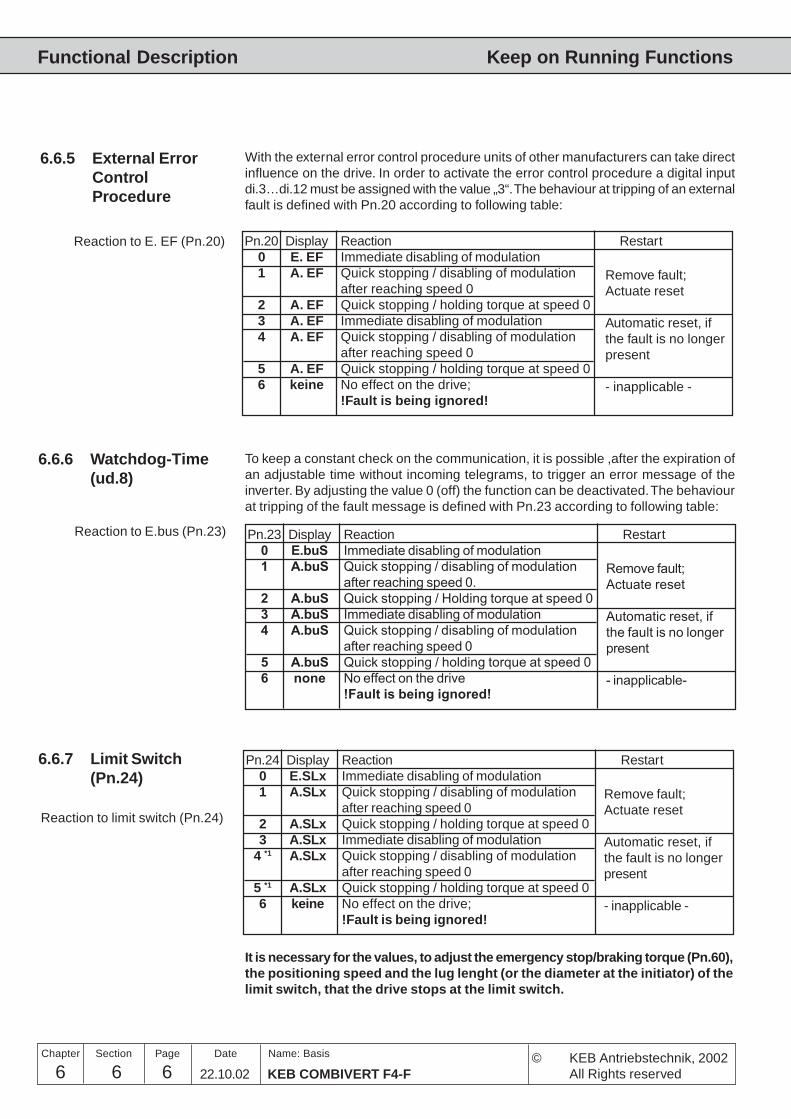
6 6 KEB COMBIVERT F4-F6Name: Basis
22.10.02
Chapter Section Page Date © KEB Antriebstechnik, 2002All Rights reserved
Functional Description Keep on Running Functions
6.6.5 External ErrorControlProcedure
With the external error control procedure units of other manufacturers can take directinfluence on the drive. In order to activate the error control procedure a digital inputdi.3…di.12 must be assigned with the value „3“. The behaviour at tripping of an externalfault is defined with Pn.20 according to following table:
Pn.20 Display Reaction Restart0 E. EF Immediate disabling of modulation1 A. EF Quick stopping / disabling of modulation
after reaching speed 02 A. EF Quick stopping / holding torque at speed 03 A. EF Immediate disabling of modulation4 A. EF Quick stopping / disabling of modulation
after reaching speed 05 A. EF Quick stopping / holding torque at speed 06 keine No effect on the drive;
!Fault is being ignored!
Remove fault;Actuate reset
Automatic reset, ifthe fault is no longerpresent
- inapplicable -
Reaction to E. EF (Pn.20)
6.6.6 Watchdog-Time(ud.8)
To keep a constant check on the communication, it is possible ,after the expiration ofan adjustable time without incoming telegrams, to trigger an error message of theinverter. By adjusting the value 0 (off) the function can be deactivated. The behaviourat tripping of the fault message is defined with Pn.23 according to following table:
Reaction to E.bus (Pn.23) Pn.23 Display Reaction Restart0 E.buS Immediate disabling of modulation1 A.buS Quick stopping / disabling of modulation
after reaching speed 0.2 A.buS Quick stopping / Holding torque at speed 03 A.buS Immediate disabling of modulation4 A.buS Quick stopping / disabling of modulation
after reaching speed 05 A.buS Quick stopping / holding torque at speed 06 none No effect on the drive
!Fault is being ignored!
Remove fault;Actuate reset
Automatic reset, ifthe fault is no longerpresent
- inapplicable-
Pn.24 Display Reaction Restart0 E.SLx Immediate disabling of modulation1 A.SLx Quick stopping / disabling of modulation
after reaching speed 02 A.SLx Quick stopping / holding torque at speed 03 A.SLx Immediate disabling of modulation
4 *1 A.SLx Quick stopping / disabling of modulationafter reaching speed 0
5 *1 A.SLx Quick stopping / holding torque at speed 06 keine No effect on the drive;
!Fault is being ignored!
Remove fault;Actuate reset
Automatic reset, ifthe fault is no longerpresent
- inapplicable -
Reaction to limit switch (Pn.24)
It is necessary for the values, to adjust the emergency stop/braking torque (Pn.60),the positioning speed and the lug lenght (or the diameter at the initiator) of thelimit switch, that the drive stops at the limit switch.
6.6.7 Limit Switch(Pn.24)
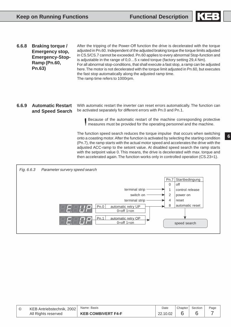
76 6 7KEB COMBIVERT F4-F
Name: Basis
22.10.02
6
Section PageDate© KEB Antriebstechnik, 2002All Rights reserved
Chapter
Functional DescriptionKeep on Running Functions
6.6.9 Automatic Restartand Speed Search
Fig. 6.6.3 Parameter survery speed search
With automatic restart the inverter can reset errors automatically. The function canbe activated separately for different errors with Pn.0 and Pn.1.
Because of the automatic restart of the machine corresponding protectivemeasures must be provided for the operating personnel and the machine.
The function speed search reduces the torque impulse that occurs when switchingonto a coasting motor. After the function is activated by selecting the starting condition(Pn.7), the ramp starts with the actual motor speed and accelerates the drive with theadjusted ACC-ramp to the setoint value. At disabled speed search the ramp startswith the setpoint value 0. This means, the drive is decelerated with max. torque andthen accelerated again. The function works only in controlled operation (CS.23=1).
Pn.0 automatic retry UP0=off 1=on
Pn.1 automatic retry OP0=off 1=on
terminal strip
switch on
terminal strip
Pn.7 Startbedingung0 off
1 control release
2 power on
4 reset
8 automatic reset
speed search
6.6.8 Braking torque /Emergency stop,Emergency-Stop-Ramp (Pn.60,Pn.63)
After the tripping of the Power-Off function the drive is decelerated with the torqueadjusted in Pn.60. Independent of the adjusted braking torque the torque limits adjustedin CS.5/CS.7 cannot be exceeded. Pn.60 applies to every abnormal Stop-function andis adjustable in the range of 0,0…5 x rated torque (factory setting 29,4 Nm).For all abnormal stop-conditions, that shall execute a fast stop, a ramp can be adjustedhere. The motor is not decelerated with the torque limit adjusted in Pn.60, but executesthe fast stop automatically along the adjusted ramp time.The ramp time refers to 1000rpm.
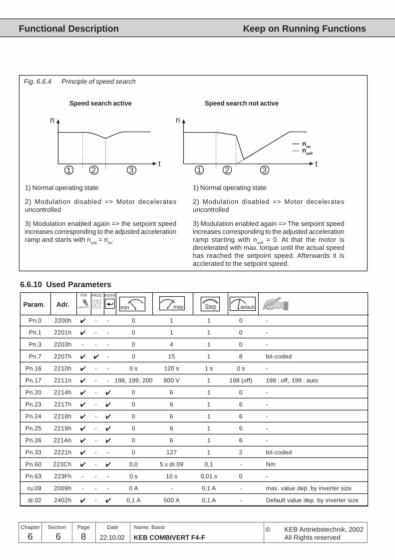
6 6 KEB COMBIVERT F4-F8Name: Basis
22.10.02
Chapter Section Page Date © KEB Antriebstechnik, 2002All Rights reserved
Functional Description Keep on Running Functions
Param. Adr. min max default
ENTERPROG.R/W
Step
Pn.0 2200h - - 0 1 1 0 -
Pn.1 2201h - - 0 1 1 0 -
Pn.3 2203h - - - 0 4 1 0 -
Pn.7 2207h - 0 15 1 8 bit-coded
Pn.16 2210h - - 0 s 120 s 1 s 0 s -
Pn.17 2211h - - 198, 199, 200 800 V 1 198 (off) 198 : off, 199 : auto
Pn.20 2214h - 0 6 1 0 -
Pn.23 2217h - 0 6 1 6 -
Pn.24 2218h - 0 6 1 6 -
Pn.25 2219h - 0 6 1 6 -
Pn.26 221Ah - 0 6 1 6 -
Pn.33 2221h - - 0 127 1 2 bit-coded
Pn.60 223Ch - 0,0 5 x dr.09 0,1 - Nm
Pn.63 223Fh - - - 0 s 10 s 0,01 s 0 -
ru.09 2009h - - - 0 A - 0,1 A - max. value dep. by inverter size
dr.02 2402h - 0,1 A 500 A 0,1 A - Default value dep. by inverter size
6.6.10 Used Parameters
Fig. 6.6.4 Principle of speed search
1) Normal operating state
2) Modulation disabled => Motor deceleratesuncontrolled
3) Modulation enabled again => the setpoint speedincreases corresponding to the adjusted accelerationramp and starts with n
soll = n
ist.
1) Normal operating state
2) Modulation disabled => Motor deceleratesuncontrolled
3) Modulation enabled again => The setpoint speedincreases corresponding to the adjusted accelerationramp starting with n
soll = 0. At that the motor is
decelerated with max. torque until the actual speedhas reached the setpoint speed. Afterwards it isacclerated to the setpoint speed.
n
t1 2 3
n
t1 2 3
Speed search active Speed search not active
nistnsoll
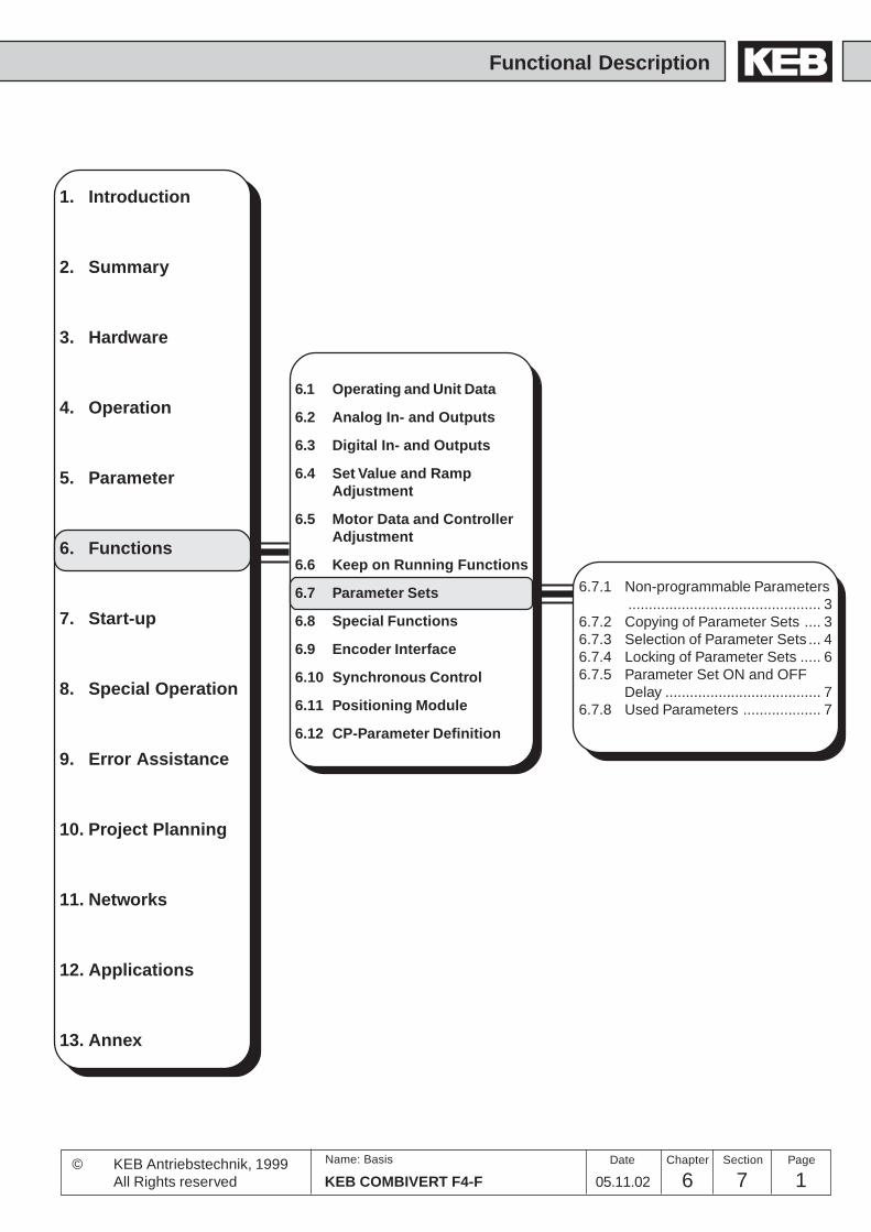
6 7 1KEB COMBIVERT F4-F
Name: Basis
05.11.02
Functional Description
Chapter Section PageDate© KEB Antriebstechnik, 1999All Rights reserved
1. Introduction
2. Summary
3. Hardware
4. Operation
5. Parameter
6. Functions
7. Start-up
8. Special Operation
9. Error Assistance
10. Project Planning
11. Networks
12. Applications
13. Annex
6.1 Operating and Unit Data
6.2 Analog In- and Outputs
6.3 Digital In- and Outputs
6.4 Set Value and RampAdjustment
6.5 Motor Data and ControllerAdjustment
6.6 Keep on Running Functions
6.7 Parameter Sets
6.8 Special Functions
6.9 Encoder Interface
6.10 Synchronous Control
6.11 Positioning Module
6.12 CP-Parameter Definition
6.7.1 Non-programmable Parameters............................................... 3
6.7.2 Copying of Parameter Sets .... 36.7.3 Selection of Parameter Sets ... 46.7.4 Locking of Parameter Sets ..... 66.7.5 Parameter Set ON and OFF
Delay ...................................... 76.7.8 Used Parameters ................... 7

6 7 KEB COMBIVERT F4-F2Name: Basis
05.11.02
Chapter Section Page Date © KEB Antriebstechnik, 2002All Rights reserved
Functional Description Parameter Sets
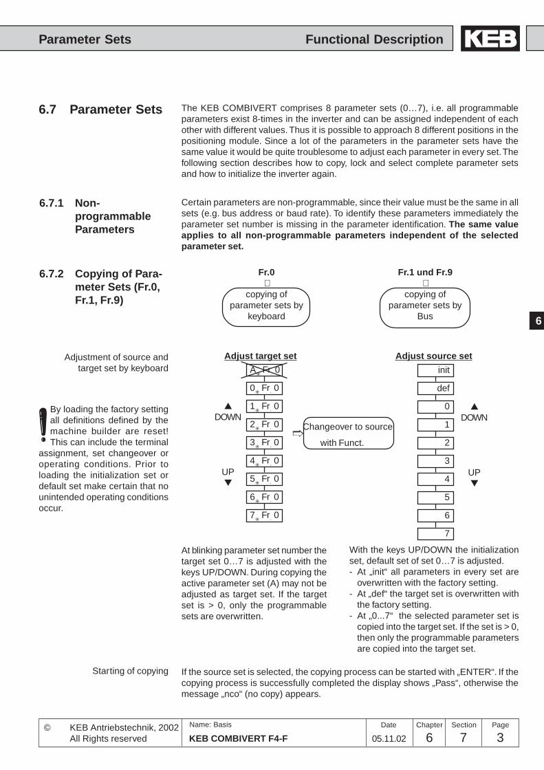
36 7 3KEB COMBIVERT F4-F
Name: Basis
05.11.02
6
Section PageDate© KEB Antriebstechnik, 2002All Rights reserved
Chapter
Functional DescriptionParameter Sets
6.7 Parameter Sets
6.7.2 Copying of Para-meter Sets (Fr.0,Fr.1, Fr.9)
The KEB COMBIVERT comprises 8 parameter sets (0…7), i.e. all programmableparameters exist 8-times in the inverter and can be assigned independent of eachother with different values. Thus it is possible to approach 8 different positions in thepositioning module. Since a lot of the parameters in the parameter sets have thesame value it would be quite troublesome to adjust each parameter in every set. Thefollowing section describes how to copy, lock and select complete parameter setsand how to initialize the inverter again.
6.7.1 Non-programmableParameters
Certain parameters are non-programmable, since their value must be the same in allsets (e.g. bus address or baud rate). To identify these parameters immediately theparameter set number is missing in the parameter identification. The same valueapplies to all non-programmable parameters independent of the selectedparameter set.
Fr.0⇓
copying ofparameter sets by
keyboard
Fr.1 und Fr.9⇓
copying ofparameter sets by
Bus
Adjustment of source andtarget set by keyboard
0 Fr
· 0
1 Fr
· 0
2 Fr
· 0
3 Fr
· 0
4 Fr
· 0
5 Fr
· 0
6 Fr
· 0
7 Fr
· 0
DOWN
UP
Adjust target set
At blinking parameter set number thetarget set 0…7 is adjusted with thekeys UP/DOWN. During copying theactive parameter set (A) may not beadjusted as target set. If the targetset is > 0, only the programmablesets are overwritten.
A Fr
· 0
1
2
3
4
5
6
7
DOWN
UP
Adjust source set
With the keys UP/DOWN the initializationset, default set of set 0…7 is adjusted.- At „init“ all parameters in every set are
overwritten with the factory setting.- At „def“ the target set is overwritten with
the factory setting.- At „0...7“ the selected parameter set is
copied into the target set. If the set is > 0,then only the programmable parametersare copied into the target set.
0
def
init
Changeover to source
with Funct.
Starting of copying If the source set is selected, the copying process can be started with „ENTER“. If thecopying process is successfully completed the display shows „Pass“, otherwise themessage „nco“ (no copy) appears.
By loading the factory settingall definitions defined by themachine builder are reset!This can include the terminal
assignment, set changeover oroperating conditions. Prior toloading the initialization set ordefault set make certain that nounintended operating conditionsoccur.
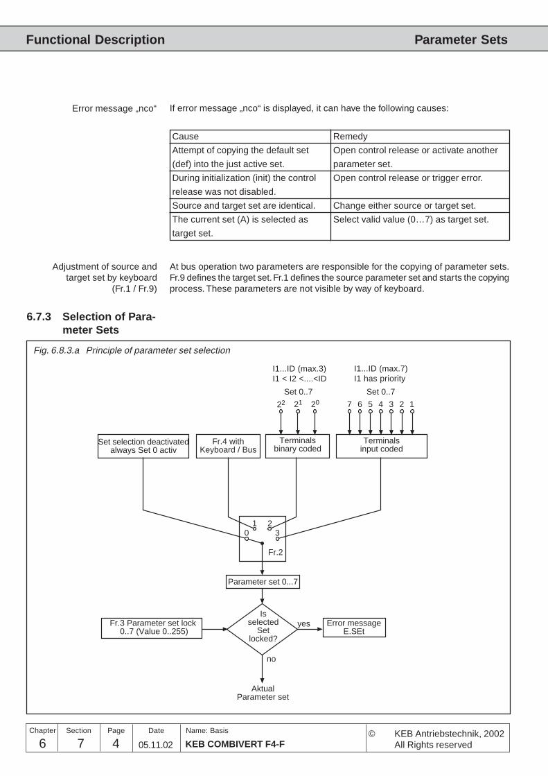
6 7 KEB COMBIVERT F4-F4Name: Basis
05.11.02
Chapter Section Page Date © KEB Antriebstechnik, 2002All Rights reserved
Functional Description Parameter Sets
Remedy
Open control release or activate another
parameter set.
Open control release or trigger error.
Change either source or target set.
Select valid value (0…7) as target set.
Fig. 6.8.3.a Principle of parameter set selection
Error message „nco“ If error message „nco“ is displayed, it can have the following causes:
Cause
Attempt of copying the default set
(def) into the just active set.
During initialization (init) the control
release was not disabled.
Source and target set are identical.
The current set (A) is selected as
target set.
Adjustment of source andtarget set by keyboard
(Fr.1 / Fr.9)
At bus operation two parameters are responsible for the copying of parameter sets.Fr.9 defines the target set. Fr.1 defines the source parameter set and starts the copyingprocess. These parameters are not visible by way of keyboard.
6.7.3 Selection of Para-meter Sets
Terminalsbinary coded
Terminalsinput coded
Fr.4 withKeyboard / Bus
Set selection deactivatedalways Set 0 activ
Fr.2
01 2
3
AktualParameter set
Parameter set 0...7
Isselected
Setlocked?
Fr.3 Parameter set lock 0..7 (Value 0..255)
no
yes Error messageE.SEt
202122 1234567
Set 0..7Set 0..7
I1...ID (max.7)I1 has priority
I1...ID (max.3)I1 < I2 <....<ID
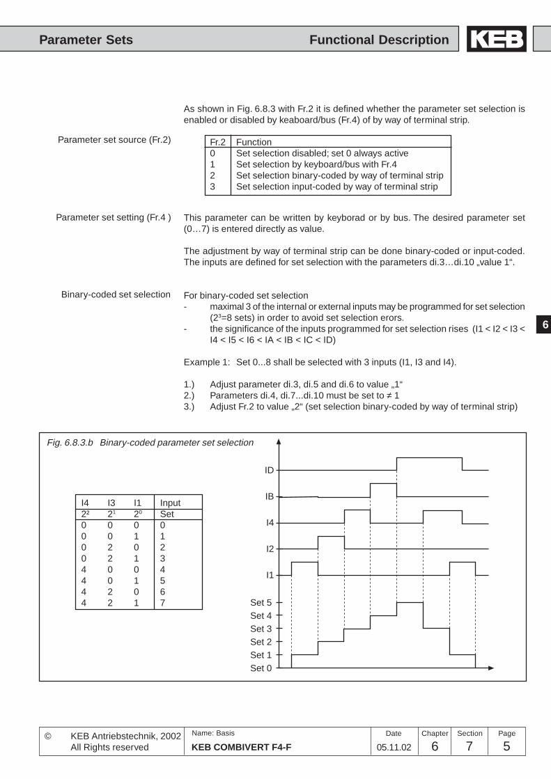
56 7 5KEB COMBIVERT F4-F
Name: Basis
05.11.02
6
Section PageDate© KEB Antriebstechnik, 2002All Rights reserved
Chapter
Functional DescriptionParameter Sets
As shown in Fig. 6.8.3 with Fr.2 it is defined whether the parameter set selection isenabled or disabled by keaboard/bus (Fr.4) of by way of terminal strip.
Fr.2 Function0 Set selection disabled; set 0 always active1 Set selection by keyboard/bus with Fr.42 Set selection binary-coded by way of terminal strip3 Set selection input-coded by way of terminal strip
Parameter set source (Fr.2)
Parameter set setting (Fr.4 ) This parameter can be written by keyborad or by bus. The desired parameter set(0…7) is entered directly as value.
The adjustment by way of terminal strip can be done binary-coded or input-coded.The inputs are defined for set selection with the parameters di.3…di.10 „value 1“.
For binary-coded set selection- maximal 3 of the internal or external inputs may be programmed for set selection
(23=8 sets) in order to avoid set selection erors.- the significance of the inputs programmed for set selection rises (I1 < I2 < I3 <
I4 < I5 < I6 < IA < IB < IC < ID)
Example 1: Set 0...8 shall be selected with 3 inputs (I1, I3 and I4).
1.) Adjust parameter di.3, di.5 and di.6 to value „1“2.) Parameters di.4, di.7...di.10 must be set to ≠ 13.) Adjust Fr.2 to value „2“ (set selection binary-coded by way of terminal strip)
Binary-coded set selection
Set 0Set 1Set 2Set 3Set 4Set 5
I1
I2
I4
IB
ID
I4 I3 I1 Input2² 21 20 Set0 0 0 00 0 1 10 2 0 20 2 1 34 0 0 44 0 1 54 2 0 64 2 1 7
Fig. 6.8.3.b Binary-coded parameter set selection
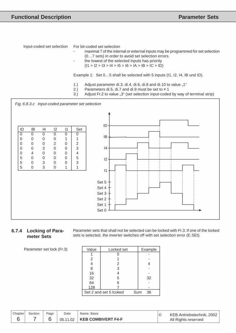
6 7 KEB COMBIVERT F4-F6Name: Basis
05.11.02
Chapter Section Page Date © KEB Antriebstechnik, 2002All Rights reserved
Functional Description Parameter Sets
Input-coded set selection
ID IB I4 I2 I1 Set0 0 0 0 0 00 0 0 0 1 10 0 0 2 0 20 0 3 0 0 30 4 0 0 0 45 0 0 0 0 55 0 3 0 0 35 0 3 0 1 1
Fig. 6.8.3.c Input-coded parameter set selection
For bit-coded set selection- maximal 7 of the internal or external inputs may be programmed for set selection
(0…7 sets) in order to avoid set selection errors.- the lowest of the selected inputs has priority
(I1 > I2 > I3 > I4 > I5 > I6 > IA > IB > IC > ID)
Example 1: Set 0…5 shall be selected with 5 inputs (I1, I2, I4, IB und ID).
1.) Adjust parameter di.3, di.4, di.6, di.8 and di.10 to value „1“2.) Parameters di.5, di.7 and di.9 must be set to ≠ 13.) Adjust Fr.2 to value „3“ (set selection input-coded by way of terminal strip)
6.7.4 Locking of Para-meter Sets
Parameter sets that shall not be selected can be locked with Fr.3. If one of the lockedsets is selected, the inverter switches off with set selection error (E.SEt).
Value Locked set Example1 0 -2 1 -4 2 48 3 -16 4 -32 5 3264 6 -128 7 -
Set 2 and set 5 lcoked Sum 36
Parameter set lock (Fr.3)
Set 0Set 1Set 2Set 3Set 4Set 5
I1
I2
I4
IB
ID
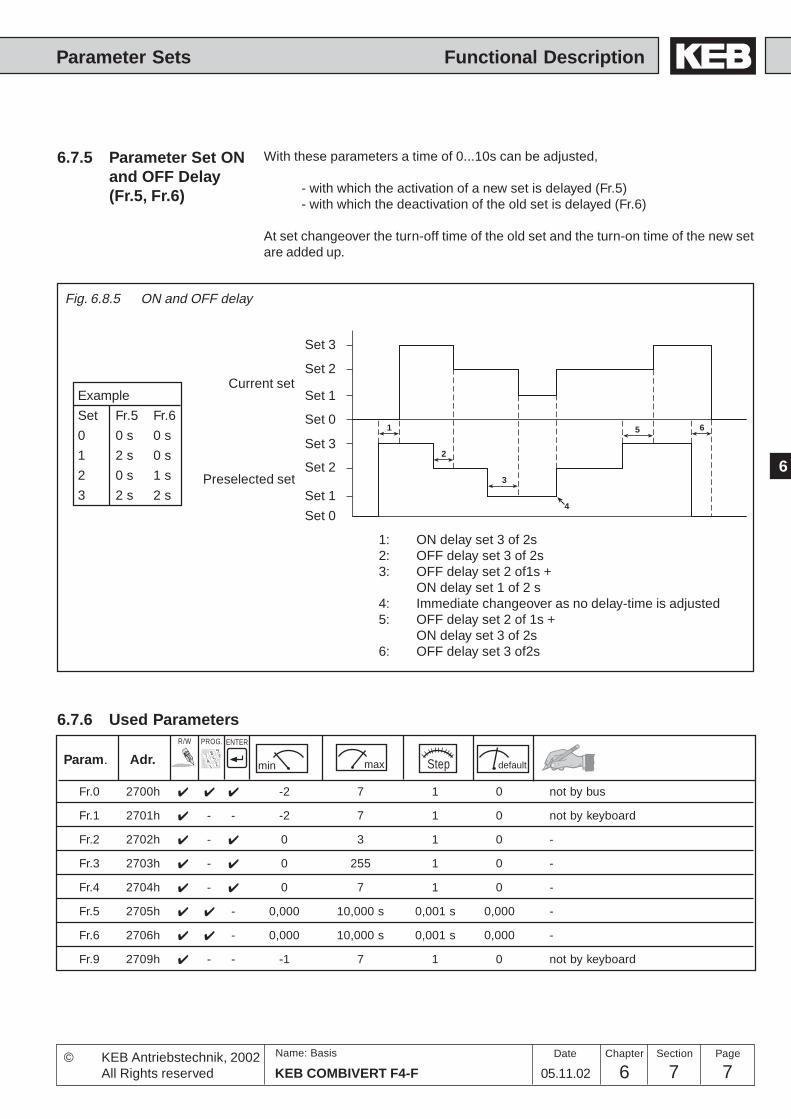
76 7 7KEB COMBIVERT F4-F
Name: Basis
05.11.02
6
Section PageDate© KEB Antriebstechnik, 2002All Rights reserved
Chapter
Functional DescriptionParameter Sets
Param. Adr. min max default
ENTERPROG.R/W
Step
65
3
2
1
4
6.7.6 Used Parameters
Fr.0 2700h -2 7 1 0 not by bus
Fr.1 2701h - - -2 7 1 0 not by keyboard
Fr.2 2702h - 0 3 1 0 -
Fr.3 2703h - 0 255 1 0 -
Fr.4 2704h - 0 7 1 0 -
Fr.5 2705h - 0,000 10,000 s 0,001 s 0,000 -
Fr.6 2706h - 0,000 10,000 s 0,001 s 0,000 -
Fr.9 2709h - - -1 7 1 0 not by keyboard
6.7.5 Parameter Set ONand OFF Delay(Fr.5, Fr.6)
With these parameters a time of 0...10s can be adjusted,
- with which the activation of a new set is delayed (Fr.5)- with which the deactivation of the old set is delayed (Fr.6)
At set changeover the turn-off time of the old set and the turn-on time of the new setare added up.
Fig. 6.8.5 ON and OFF delay
Example
Set Fr.5 Fr.6
0 0 s 0 s
1 2 s 0 s
2 0 s 1 s
3 2 s 2 s
1: ON delay set 3 of 2s2: OFF delay set 3 of 2s3: OFF delay set 2 of1s +
ON delay set 1 of 2 s4: Immediate changeover as no delay-time is adjusted5: OFF delay set 2 of 1s +
ON delay set 3 of 2s6: OFF delay set 3 of2s
Set 1
Set 3
Set 2
Set 1
Set 3
Set 2
Set 0
Set 0
Preselected set
Current set

6 7 KEB COMBIVERT F4-F8Name: Basis
05.11.02
Chapter Section Page Date © KEB Antriebstechnik, 2002All Rights reserved
Functional Description Parameter Sets
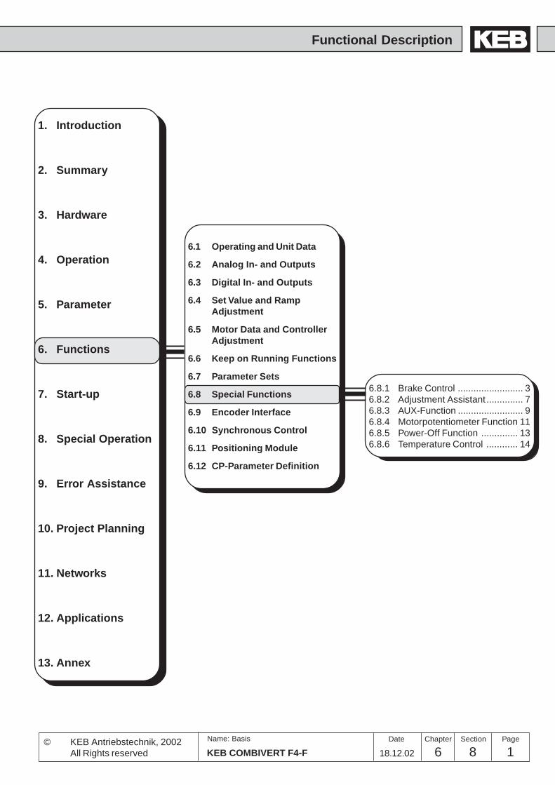
6 8 1KEB COMBIVERT F4-F
Name: Basis
Functional Description
Chapter Section PageDate
1. Introduction
2. Summary
3. Hardware
4. Operation
5. Parameter
6. Functions
7. Start-up
8. Special Operation
9. Error Assistance
10. Project Planning
11. Networks
12. Applications
13. Annex
6.1 Operating and Unit Data
6.2 Analog In- and Outputs
6.3 Digital In- and Outputs
6.4 Set Value and RampAdjustment
6.5 Motor Data and ControllerAdjustment
6.6 Keep on Running Functions
6.7 Parameter Sets
6.8 Special Functions
6.9 Encoder Interface
6.10 Synchronous Control
6.11 Positioning Module
6.12 CP-Parameter Definition
18.12.02© KEB Antriebstechnik, 2002
All Rights reserved
6.8.1 Brake Control ......................... 36.8.2 Adjustment Assistant .............. 76.8.3 AUX-Function ......................... 96.8.4 Motorpotentiometer Function 116.8.5 Power-Off Function .............. 136.8.6 Temperature Control ............ 14

6 8 KEB COMBIVERT F4-F2Name: BasisChapter Section Page Date
Functional Description Special Functions
18.12.02© KEB Antriebstechnik, 2002
All Rights reserved
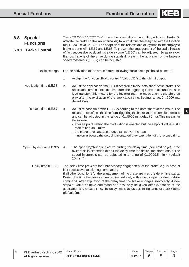
36 8 3KEB COMBIVERT F4-F
Name: Basis
6
Section PageDate Chapter
Functional DescriptionSpecial Functions
18.12.02© KEB Antriebstechnik, 2002
All Rights reserved
6.8.1 Brake Control
The KEB COMBIVERT F4-F offers the possibility of controlling a holding brake. Toactivate the brake control an external digital output must be assigned with the function(do.1…do.8 = value „32“). The adaption of the release and delay time to the employedbrake is done with LE.67 and LE.68. To prevent the engagement of the brake in caseof fast successive positionings a delay time (LE.66) can be adjusted. So as to avoidthat oscillations of the drive during standstill prevent the activation of the brake aspeed hysteresis (LE.37) can be adjusted.
Basic settings
Speed hysteresis (LE.37)
For the activation of the brake control following basic settings should be made:
1. Assign the function „Brake control“ (value „32“) to the digital output.
2. Adjust the application time LE.68 according to the data sheet of the brake. Theapplication time defines the time from the triggering of the brake until the safeload transfer. This means for the inverter that the modulation is switched offonly after the expiration of the application time. Setting range: 0…5000 ms,default 0ms.
3. Adjust release time with LE.67 according to the data sheet of the brake. Therelease time defines the time from triggering the brake until the complete releaseand can be adjusted in the range of 0…5000ms (default 0ms). This means forthe inverter- after setpoint setting the modulation is enabled but the setpoint value is still
maintained on 0 min-1
- the brake is released, the drive takes over the load- if no error occurs the setpoint is enabled after expiration of the release time.
4. The speed hysteresis is active durting the delay time (see next page). If thehysteresis is exceeded during the delay time the delay time starts again. Thespeed hysteresis can be adjusted in a range of 0...9999,5 min-1 (default10 min-1).
Application time (LE.68)
Release time (LE.67)
6.8 SpecialFunctions
Delay time (LE.66) The delay time prevents the unnecessary engagement of the brake, e.g. in case offast successive positioning commands.If all other conditions for the engagement of the brake are met, the delay time starts.During this time the drive can restart immediately with a new setpoint value or drivecommand. After expiration of the delay time the brake engages irrevocably. A newsetpoint value or drive command can now only be given after expiration of theapplication and release time. The delay time is adjustable in the range of 0...65535ms(default 0ms).
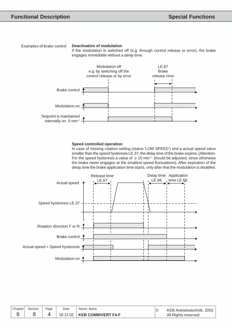
6 8 KEB COMBIVERT F4-F4Name: BasisChapter Section Page Date
Functional Description Special Functions
18.12.02© KEB Antriebstechnik, 2002
All Rights reserved
Examples of brake control Deactivation of modulationIf the modulation is switched off (e.g. through control release or error), the brakeengages immediatle without a delay time.
Brake control
Modulation on
Setpoint is maintainedinternally on 0 min-1
Modulation offe.g. by switching off the
control release or by error
LE.67Brake
release rime
Speed controlled operationIn case of missing rotation setting (status ‘LOW SPEED’) and a actual speed valuesmaller than the speed hysteresis LE.37, the delay time of the brake expires. (Attention:For the speed hysteresis a value of ≥ 15 min-1 should be adjusted, since otherwisethe brake never engages at the smallest speed fluctuations). After expiration of thedelay time the brake application time starts, only after that the modulation is disabled.
Actual speed
Modulation on
Actual speed < Speed hysteresis
Brake control
Rotation direction F or R
Speed hysteresis LE.37
Release timeLE.67
Delay timeLE.66
Applicationtime LE.68
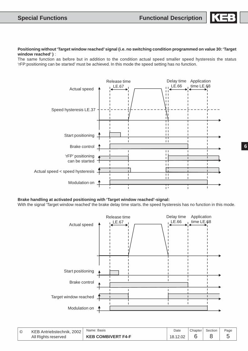
56 8 5KEB COMBIVERT F4-F
Name: Basis
6
Section PageDate Chapter
Functional DescriptionSpecial Functions
18.12.02© KEB Antriebstechnik, 2002
All Rights reserved
Positioning without ‘Target window reached’ signal (i.e. no switching condition programmed on value 30: ‘Targetwindow reached’ ) :The same function as before but in addition to the condition actual speed smaller speed hysteresis the status‘rFP:positioning can be started’ must be achieved. In this mode the speed setting has no function.
Brake handling at activated positioning with ‘Target window reached’-signal:With the signal ‘Target window reached’ the brake delay time starts. the speed hysteresis has no function in this mode.
Actual speed
Modulation on
Actual speed < speed hysteresis
Brake control
Start positioning
Release timeLE.67
Delay timeLE.66
Applicationtime LE.68
‘rFP’ positioningcan be started
Actual speed
Modulation on
Target window reached
Brake control
Start positioning
Release timeLE.67
Delay timeLE.66
Applicationtime LE.68
Speed hysteresis LE.37
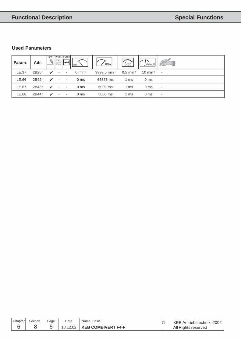
6 8 KEB COMBIVERT F4-F6Name: BasisChapter Section Page Date
Functional Description Special Functions
18.12.02© KEB Antriebstechnik, 2002
All Rights reserved
Param. Adr. min max default
ENTERPROG.R/W
Step
Used Parameters
LE.37 2B25h - - 0 min-1 9999,5 min-1 0,5 min-1 10 min-1 -
LE.66 2B42h - - 0 ms 65535 ms 1 ms 0 ms -
LE.67 2B43h - - 0 ms 5000 ms 1 ms 0 ms -
LE.68 2B44h - - 0 ms 5000 ms 1 ms 0 ms -
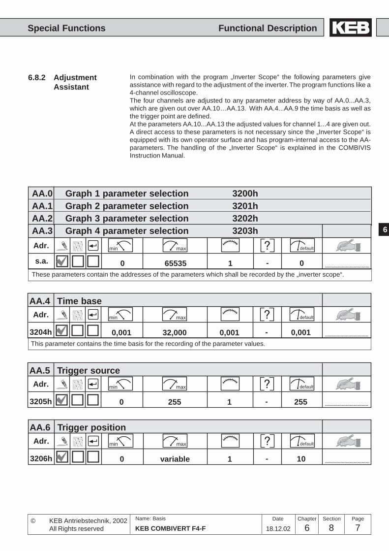
76 8 7KEB COMBIVERT F4-F
Name: Basis
6
Section PageDate Chapter
Functional DescriptionSpecial Functions
18.12.02© KEB Antriebstechnik, 2002
All Rights reserved
Adr. min max default
6.8.2 AdjustmentAssistant
In combination with the program „Inverter Scope“ the following parameters giveassistance with regard to the adjustment of the inverter. The program functions like a4-channel oscilloscope.The four channels are adjusted to any parameter address by way of AA.0...AA.3,which are given out over AA.10…AA.13. With AA.4...AA.9 the time basis as well asthe trigger point are defined.At the parameters AA.10...AA.13 the adjusted values for channel 1...4 are given out.A direct access to these parameters is not necessary since the „Inverter Scope“ isequipped with its own operator surface and has program-internal access to the AA-parameters. The handling of the „Inverter Scope“ is explained in the COMBIVISInstruction Manual.
Adr. min max default
1 - 0655350s.a.
These parameters contain the addresses of the parameters which shall be recorded by the „inverter scope“.
AA.0 Graph 1 parameter selection 3200hAA.1 Graph 2 parameter selection 3201hAA.2 Graph 3 parameter selection 3202hAA.3 Graph 4 parameter selection 3203h
3204h 0,001 - 0,00132,0000,001This parameter contains the time basis for the recording of the parameter values.
AA.4 Time base
Adr. min max default
3205h 1 - 2552550
AA.5 Trigger source
Adr. min max default
3206h 1 - 10variable0
AA.6 Trigger position

6 8 KEB COMBIVERT F4-F8Name: BasisChapter Section Page Date
Functional Description Special Functions
18.12.02© KEB Antriebstechnik, 2002
All Rights reserved
Adr. min max default
3207h 1 - 032767-32767This parameter serves to synchronize the PC-program with the inverter.
AA.7 Synchronisation
Adr. min max default
3208h 1 - 020This parameter serves to sychnronize the PC-program with the inverter.
AA.8 Trigger status
Adr. min max default
3209h 1 - 0variable0This parameter serves for the readout of the values recorded in the unit.
AA.9 Sélect graph address
Adr. min max default
1 -0s.a.
These parameters serve for the readout of the values recorded in the unit.
AA.10 Read graph 1 320AhAA.11 Read graph 2 320BhAA.12 Read graph 3 320ChAA.13 Read graph 4 320Dh
- -
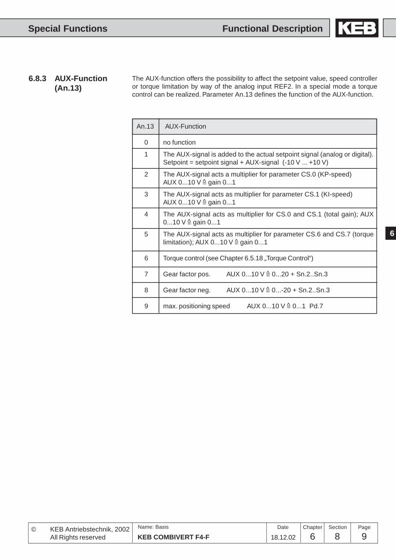
96 8 9KEB COMBIVERT F4-F
Name: Basis
6
Section PageDate Chapter
Functional DescriptionSpecial Functions
18.12.02© KEB Antriebstechnik, 2002
All Rights reserved
The AUX-function offers the possibility to affect the setpoint value, speed controlleror torque limitation by way of the analog input REF2. In a special mode a torquecontrol can be realized. Parameter An.13 defines the function of the AUX-function.
An.13 AUX-Function
0 no function
1 The AUX-signal is added to the actual setpoint signal (analog or digital).Setpoint = setpoint signal + AUX-signal (-10 V ... +10 V)
2 The AUX-signal acts a multiplier for parameter CS.0 (KP-speed)AUX 0...10 V = gain 0...1
3 The AUX-signal acts as multiplier for parameter CS.1 (KI-speed)AUX 0...10 V = gain 0...1
4 The AUX-signal acts as multiplier for CS.0 and CS.1 (total gain); AUX0...10 V = gain 0...1
5 The AUX-signal acts as multiplier for parameter CS.6 and CS.7 (torquelimitation); AUX 0...10 V = gain 0...1
6 Torque control (see Chapter 6.5.18 „Torque Control“)
7 Gear factor pos. AUX 0...10 V = 0...20 + Sn.2..Sn.3
8 Gear factor neg. AUX 0...10 V = 0...-20 + Sn.2..Sn.3
9 max. positioning speed AUX 0...10 V = 0...1 Pd.7
6.8.3 AUX-Function(An.13)

6 8 KEB COMBIVERT F4-F10Name: BasisChapter Section Page Date
Functional Description Special Functions
18.12.02© KEB Antriebstechnik, 2002
All Rights reserved

116 8 11KEB COMBIVERT F4-F
Name: Basis
6
Section PageDate Chapter
Functional DescriptionSpecial Functions
18.12.02© KEB Antriebstechnik, 2002
All Rights reserved
6.8.4 Motor-potentiometerFunction
This function simulates a mechanic motor potentiometer. By way of two programmableinputs the value of the motor potentiometer can be increased or decreased.
100%
0%
t [s]
0%
-100%
16 33 66
SP.29
163366SP.29
8 4 2 1x x x 0x x x 1x x 0 xx x 1 x0 0 x x0 1 x x1 0 x x1 1 x x
SP.26 Motorpoti / FunctionMeaningset programmblenon-set programmbleno motor potentiometer resetreset after Power on0...100 % in 16 s0...100 % in 33 s0...100 % in 66 s0...100 % accord. to SP.29
SP.27 0,00...300,00 sMotorpoti time
n [min-1]
nmax
(SP.5)
nmin
(SP.4)
nmin
(SP.6)
nmax
(SP.7)
Increase of motorpoti valueassign value „13“ to prog.
input di.3...12
Decrease motorpoti valueassign value „14“ to prog.
input di.3...12
Rotation+ = forward- = reverse
Setpoint
Fig. 6.8.4 Motorpotentiometer function
Speed setting Setpoint setting
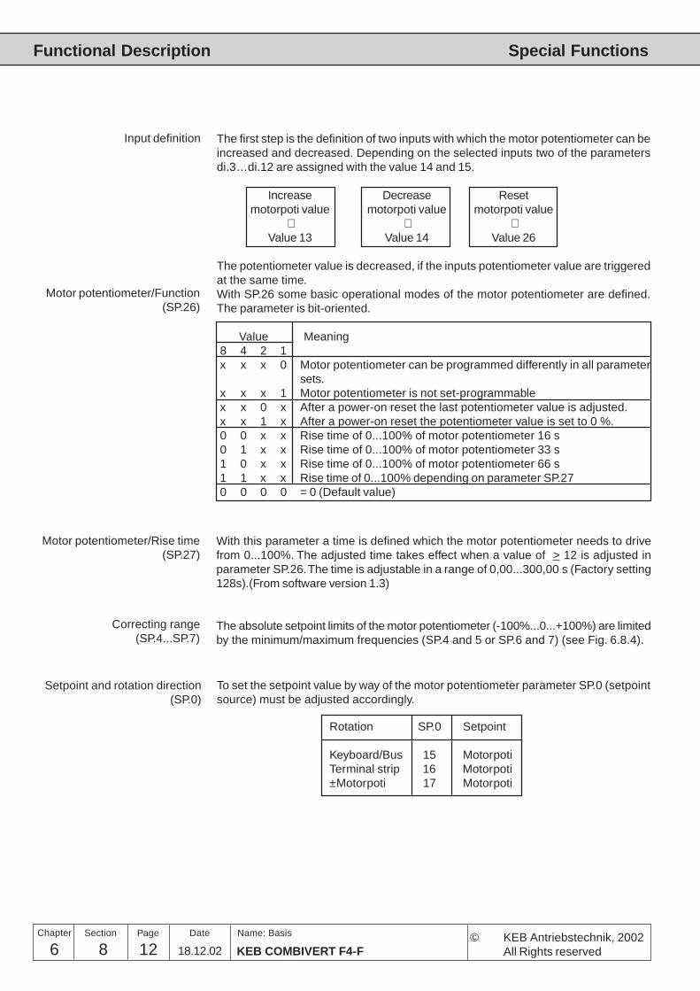
6 8 KEB COMBIVERT F4-F12Name: BasisChapter Section Page Date
Functional Description Special Functions
18.12.02© KEB Antriebstechnik, 2002
All Rights reserved
The first step is the definition of two inputs with which the motor potentiometer can beincreased and decreased. Depending on the selected inputs two of the parametersdi.3…di.12 are assigned with the value 14 and 15.
Increase Decrease Resetmotorpoti value motorpoti value motorpoti value
⇓ ⇓ ⇓Value 13 Value 14 Value 26
The potentiometer value is decreased, if the inputs potentiometer value are triggeredat the same time.With SP.26 some basic operational modes of the motor potentiometer are defined.The parameter is bit-oriented.
Value Meaning8 4 2 1x x x 0 Motor potentiometer can be programmed differently in all parameter
sets.x x x 1 Motor potentiometer is not set-programmablex x 0 x After a power-on reset the last potentiometer value is adjusted.x x 1 x After a power-on reset the potentiometer value is set to 0 %.0 0 x x Rise time of 0...100% of motor potentiometer 16 s0 1 x x Rise time of 0...100% of motor potentiometer 33 s1 0 x x Rise time of 0...100% of motor potentiometer 66 s1 1 x x Rise time of 0...100% depending on parameter SP.270 0 0 0 = 0 (Default value)
Input definition
Motor potentiometer/Rise time(SP.27)
Motor potentiometer/Function(SP.26)
Correcting range(SP.4...SP.7)
Setpoint and rotation direction(SP.0)
To set the setpoint value by way of the motor potentiometer parameter SP.0 (setpointsource) must be adjusted accordingly.
Rotation SP.0 Setpoint
Keyboard/Bus 15 MotorpotiTerminal strip 16 Motorpoti±Motorpoti 17 Motorpoti
With this parameter a time is defined which the motor potentiometer needs to drivefrom 0...100%. The adjusted time takes effect when a value of > 12 is adjusted inparameter SP.26. The time is adjustable in a range of 0,00...300,00 s (Factory setting128s).(From software version 1.3)
The absolute setpoint limits of the motor potentiometer (-100%...0...+100%) are limitedby the minimum/maximum frequencies (SP.4 and 5 or SP.6 and 7) (see Fig. 6.8.4).
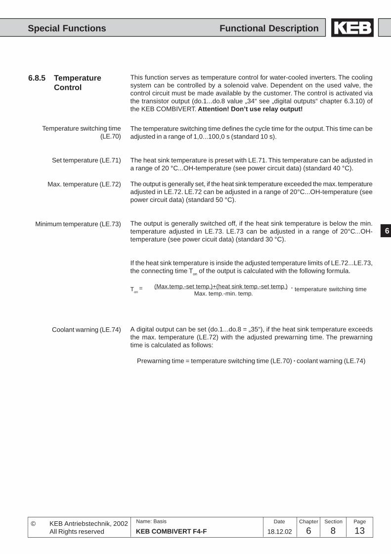
136 8 13KEB COMBIVERT F4-F
Name: Basis
6
Section PageDate Chapter
Functional DescriptionSpecial Functions
18.12.02© KEB Antriebstechnik, 2002
All Rights reserved
6.8.5 TemperatureControl
This function serves as temperature control for water-cooled inverters. The coolingsystem can be controlled by a solenoid valve. Dependent on the used valve, thecontrol circuit must be made available by the customer. The control is activated viathe transistor output (do.1...do.8 value „34“ see „digital outputs“ chapter 6.3.10) ofthe KEB COMBIVERT. Attention! Don’t use relay output!
Temperature switching time(LE.70)
The temperature switching time defines the cycle time for the output. This time can beadjusted in a range of 1,0...100,0 s (standard 10 s).
The heat sink temperature is preset with LE.71. This temperature can be adjusted ina range of 20 °C...OH-temperature (see power circuit data) (standard 40 °C).
The output is generally set, if the heat sink temperature exceeded the max. temperatureadjusted in LE.72. LE.72 can be adjusted in a range of 20°C...OH-temperature (seepower circuit data) (standard 50 °C).
The output is generally switched off, if the heat sink temperature is below the min.temperature adjusted in LE.73. LE.73 can be adjusted in a range of 20°C...OH-temperature (see power cicuit data) (standard 30 °C).
If the heat sink temperature is inside the adjusted temperature limits of LE.72...LE.73,the connecting time T
on of the output is calculated with the following formula.
Ton =(Max.temp.-set temp.)+(heat sink temp.-set temp.) . temperature switching time
Max. temp.-min. temp.
Set temperature (LE.71)
Max. temperature (LE.72)
Minimum temperature (LE.73)
Coolant warning (LE.74) A digital output can be set (do.1...do.8 = „35“), if the heat sink temperature exceedsthe max. temperature (LE.72) with the adjusted prewarning time. The prewarningtime is calculated as follows:
Prewarning time = temperature switching time (LE.70) · coolant warning (LE.74)
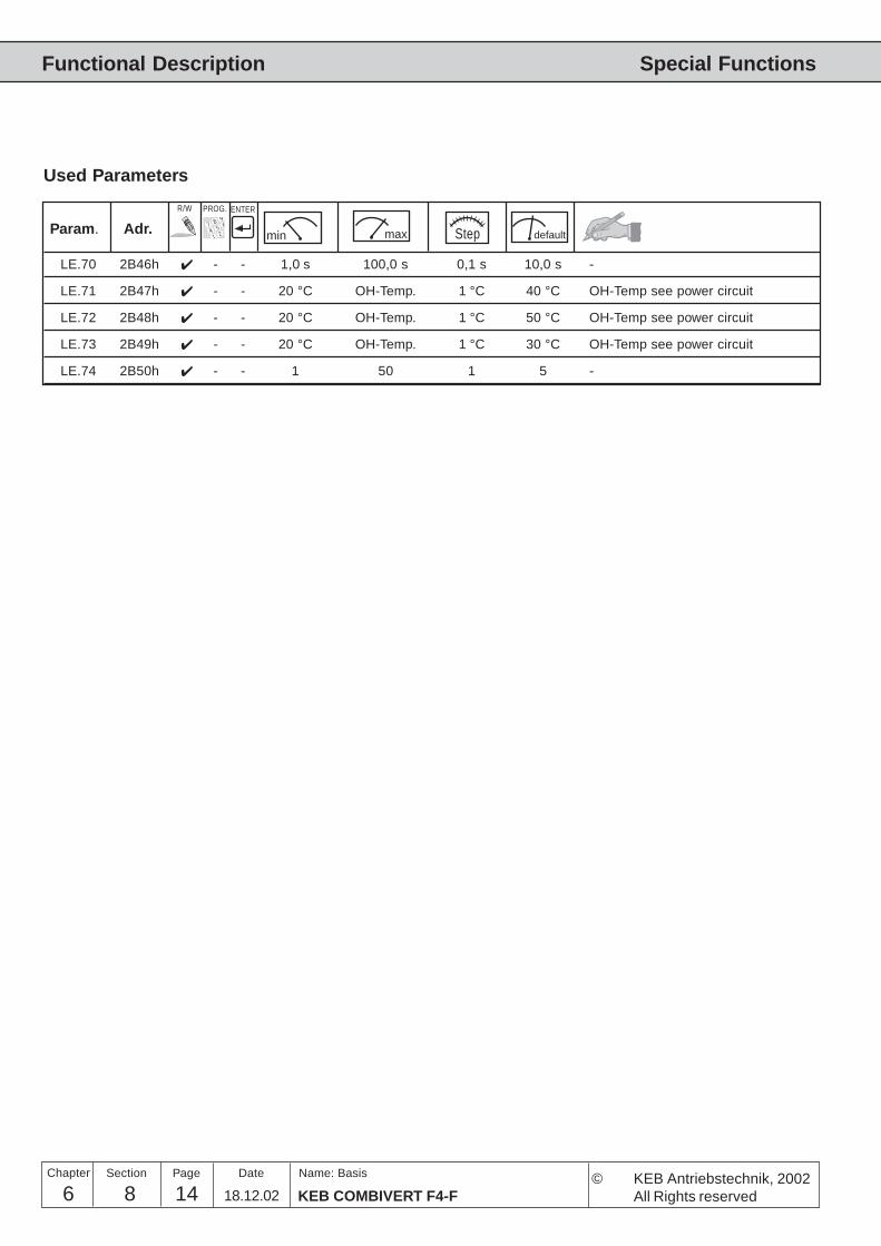
6 8 KEB COMBIVERT F4-F14Name: BasisChapter Section Page Date
Functional Description Special Functions
18.12.02© KEB Antriebstechnik, 2002
All Rights reserved
Param. Adr. min max default
ENTERPROG.R/W
Step
Used Parameters
LE.70 2B46h - - 1,0 s 100,0 s 0,1 s 10,0 s -
LE.71 2B47h - - 20 °C OH-Temp. 1 °C 40 °C OH-Temp see power circuit
LE.72 2B48h - - 20 °C OH-Temp. 1 °C 50 °C OH-Temp see power circuit
LE.73 2B49h - - 20 °C OH-Temp. 1 °C 30 °C OH-Temp see power circuit
LE.74 2B50h - - 1 50 1 5 -
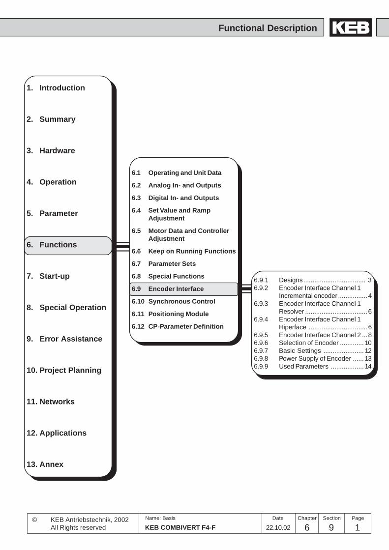
6 9 1KEB COMBIVERT F4-F
Name: Basis
22.10.02
Functional Description
Chapter Section PageDate© KEB Antriebstechnik, 2002All Rights reserved
1. Introduction
2. Summary
3. Hardware
4. Operation
5. Parameter
6. Functions
7. Start-up
8. Special Operation
9. Error Assistance
10. Project Planning
11. Networks
12. Applications
13. Annex
6.1 Operating and Unit Data
6.2 Analog In- and Outputs
6.3 Digital In- and Outputs
6.4 Set Value and RampAdjustment
6.5 Motor Data and ControllerAdjustment
6.6 Keep on Running Functions
6.7 Parameter Sets
6.8 Special Functions
6.9 Encoder Interface
6.10 Synchronous Control
6.11 Positioning Module
6.12 CP-Parameter Definition
6.9.1 Designs.................................. 36.9.2 Encoder Interface Channel 1
Incremental encoder ................46.9.3 Encoder Interface Channel 1
Resolver ..................................66.9.4 Encoder Interface Channel 1
Hiperface ................................66.9.5 Encoder Interface Channel 2 ...86.9.6 Selection of Encoder ............. 106.9.7 Basic Settings ...................... 126.9.8 Power Supply of Encoder ...... 136.9.9 Used Parameters .................. 14

6 9 KEB COMBIVERT F4-F2Name: Basis
22.10.02
Chapter Section Page Date © KEB Antriebstechnik, 2002All Rights reserved
Functional Description Encoder Interface
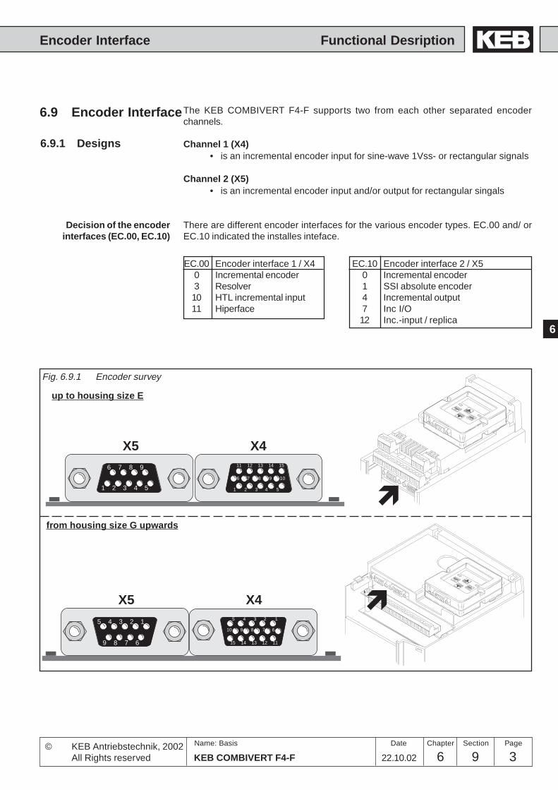
36 9 3KEB COMBIVERT F4-F
Name: Basis
22.10.02
6
Section PageDate© KEB Antriebstechnik, 2002All Rights reserved
Chapter
Functional DesriptionEncoder Interface
STARTSTOP
ENTERF/R
FUNC.SPEED
STARTSTOP
ENTERF/R
FUNC.SPEED
6.9 Encoder Interface
6.9.1 Designs
The KEB COMBIVERT F4-F supports two from each other separated encoderchannels.
Channel 1 (X4)• is an incremental encoder input for sine-wave 1Vss- or rectangular signals
Channel 2 (X5)• is an incremental encoder input and/or output for rectangular singals
Fig. 6.9.1 Encoder survey
from housing size G upwards
up to housing size E
1 2 3 4 5
6 7 8 9 10
11 12 13 14 15
1 2 3 4 5
6 7 8 9
X5 X4
5 4 3 2 1
9 8 7 6
5 4 3 2 1
9 8 7 6
5 4 3 2 1
10 9 8 7 6
15 14 13 12 11
X5 X4
EC.00 Encoder interface 1 / X40 Incremental encoder3 Resolver10 HTL incremental input11 Hiperface
EC.10 Encoder interface 2 / X50 Incremental encoder1 SSI absolute encoder4 Incremental output7 Inc I/O12 Inc.-input / replica
Decision of the encoderinterfaces (EC.00, EC.10)
There are different encoder interfaces for the various encoder types. EC.00 and/ orEC.10 indicated the installes inteface.
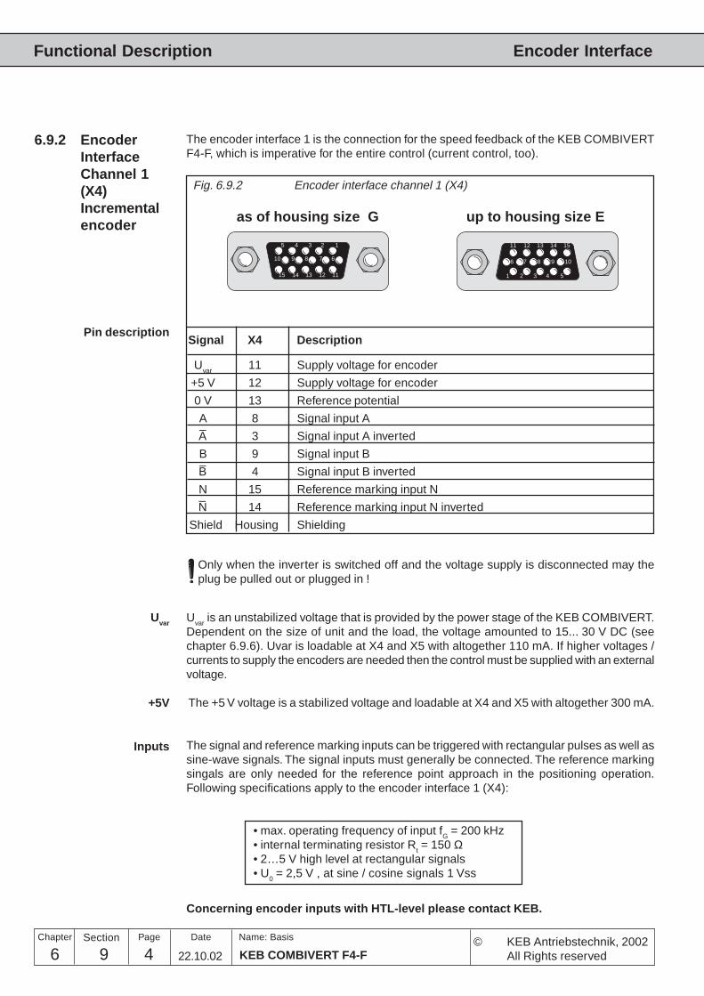
6 9 KEB COMBIVERT F4-F4Name: Basis
22.10.02
Chapter Section Page Date © KEB Antriebstechnik, 2002All Rights reserved
Functional Description Encoder Interface
1 2 3 4 5
6 7 8 9 10
11 12 13 14 155 4 3 2 1
10 9 8 7 6
15 14 13 12 11
6.9.2 EncoderInterfaceChannel 1(X4)Incrementalencoder
Fig. 6.9.2 Encoder interface channel 1 (X4)
Signal X4 Description
Uvar
11 Supply voltage for encoder
+5 V 12 Supply voltage for encoder
0 V 13 Reference potential
A 8 Signal input A_A 3 Signal input A inverted
B 9 Signal input B_B 4 Signal input B inverted
N 15 Reference marking input N_N 14 Reference marking input N inverted
Shield Housing Shielding
Uvar
is an unstabilized voltage that is provided by the power stage of the KEB COMBIVERT.Dependent on the size of unit and the load, the voltage amounted to 15... 30 V DC (seechapter 6.9.6). Uvar is loadable at X4 and X5 with altogether 110 mA. If higher voltages /currents to supply the encoders are needed then the control must be supplied with an externalvoltage.
The +5 V voltage is a stabilized voltage and loadable at X4 and X5 with altogether 300 mA.
The signal and reference marking inputs can be triggered with rectangular pulses as well assine-wave signals. The signal inputs must generally be connected. The reference markingsingals are only needed for the reference point approach in the positioning operation.Following specifications apply to the encoder interface 1 (X4):
• max. operating frequency of input fG
= 200 kHz• internal terminating resistor R
t= 150 Ω
• 2…5 V high level at rectangular signals• U
0= 2,5 V , at sine / cosine signals 1 Vss
Uvar
as of housing size G up to housing size E
Pin description
Inputs
Concerning encoder inputs with HTL-level please contact KEB.
The encoder interface 1 is the connection for the speed feedback of the KEB COMBIVERTF4-F, which is imperative for the entire control (current control, too).
+5V
Only when the inverter is switched off and the voltage supply is disconnected may theplug be pulled out or plugged in !
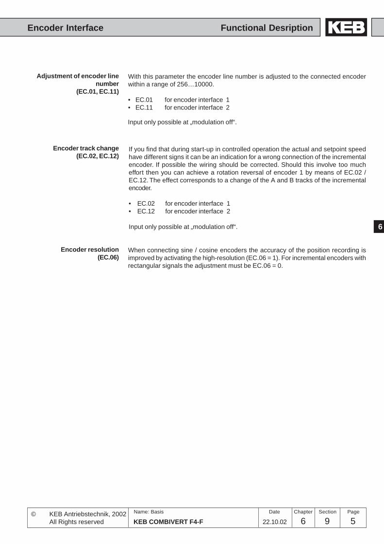
56 9 5KEB COMBIVERT F4-F
Name: Basis
22.10.02
6
Section PageDate© KEB Antriebstechnik, 2002All Rights reserved
Chapter
Functional DesriptionEncoder Interface
Adjustment of encoder linenumber
(EC.01, EC.11)
With this parameter the encoder line number is adjusted to the connected encoderwithin a range of 256…10000.
• EC.01 for encoder interface 1• EC.11 for encoder interface 2
Encoder track change(EC.02, EC.12)
If you find that during start-up in controlled operation the actual and setpoint speedhave different signs it can be an indication for a wrong connection of the incrementalencoder. If possible the wiring should be corrected. Should this involve too mucheffort then you can achieve a rotation reversal of encoder 1 by means of EC.02 /EC.12. The effect corresponds to a change of the A and B tracks of the incrementalencoder.
• EC.02 for encoder interface 1• EC.12 for encoder interface 2
Input only possible at „modulation off“.
Encoder resolution(EC.06)
When connecting sine / cosine encoders the accuracy of the position recording isimproved by activating the high-resolution (EC.06 = 1). For incremental encoders withrectangular signals the adjustment must be EC.06 = 0.
Input only possible at „modulation off“.
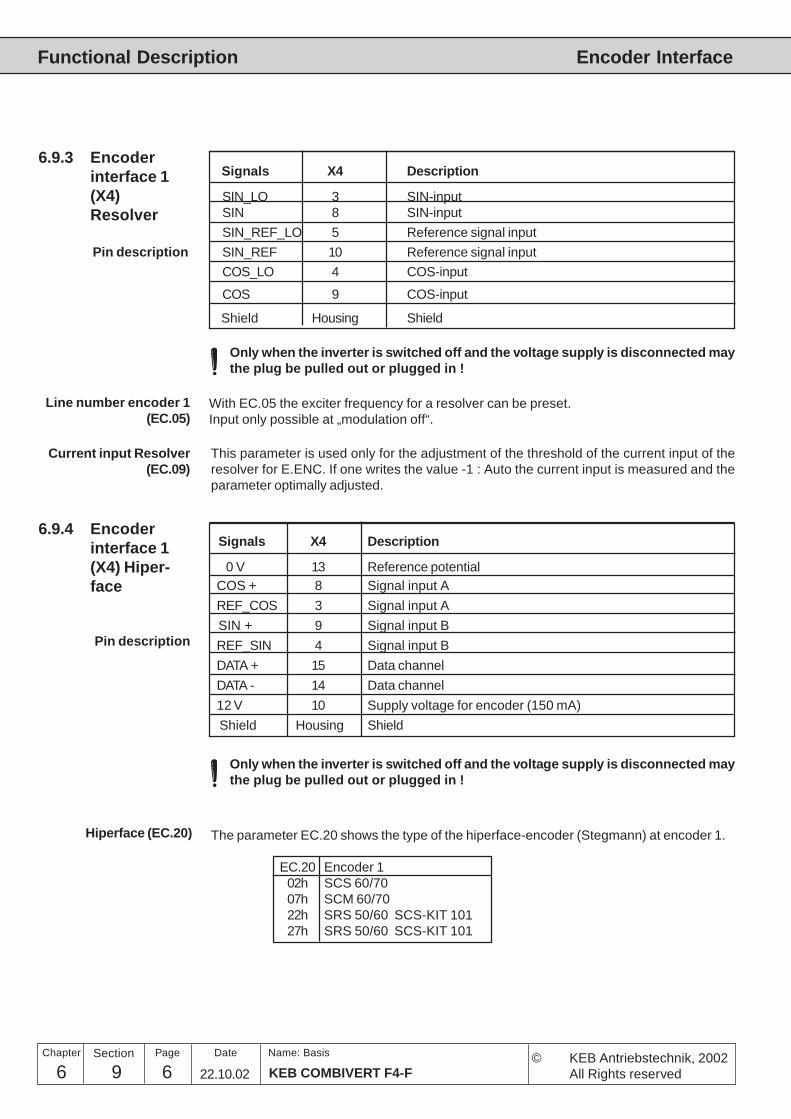
6 9 KEB COMBIVERT F4-F6Name: Basis
22.10.02
Chapter Section Page Date © KEB Antriebstechnik, 2002All Rights reserved
Functional Description Encoder Interface
Hiperface (EC.20) The parameter EC.20 shows the type of the hiperface-encoder (Stegmann) at encoder 1.
EC.20 Encoder 102h SCS 60/7007h SCM 60/7022h SRS 50/60 SCS-KIT 10127h SRS 50/60 SCS-KIT 101
6.9.3 Encoderinterface 1(X4)Resolver
Signals X4 Description
SIN_LO 3 SIN-inputSIN 8 SIN-input
SIN_REF_LO 5 Reference signal input
SIN_REF 10 Reference signal input
COS_LO 4 COS-input
COS 9 COS-input
Shield Housing Shield
Pin description
Line number encoder 1(EC.05)
Current input Resolver(EC.09)
This parameter is used only for the adjustment of the threshold of the current input of theresolver for E.ENC. If one writes the value -1 : Auto the current input is measured and theparameter optimally adjusted.
6.9.4 Encoderinterface 1(X4) Hiper-face
Signals X4 Description
0 V 13 Reference potentialCOS + 8 Signal input A
REF_COS 3 Signal input A
SIN + 9 Signal input B
REF_SIN 4 Signal input B
DATA + 15 Data channel
DATA - 14 Data channel
12 V 10 Supply voltage for encoder (150 mA)
Shield Housing Shield
Pin description
Only when the inverter is switched off and the voltage supply is disconnected maythe plug be pulled out or plugged in !
Only when the inverter is switched off and the voltage supply is disconnected maythe plug be pulled out or plugged in !
With EC.05 the exciter frequency for a resolver can be preset.Input only possible at „modulation off“.
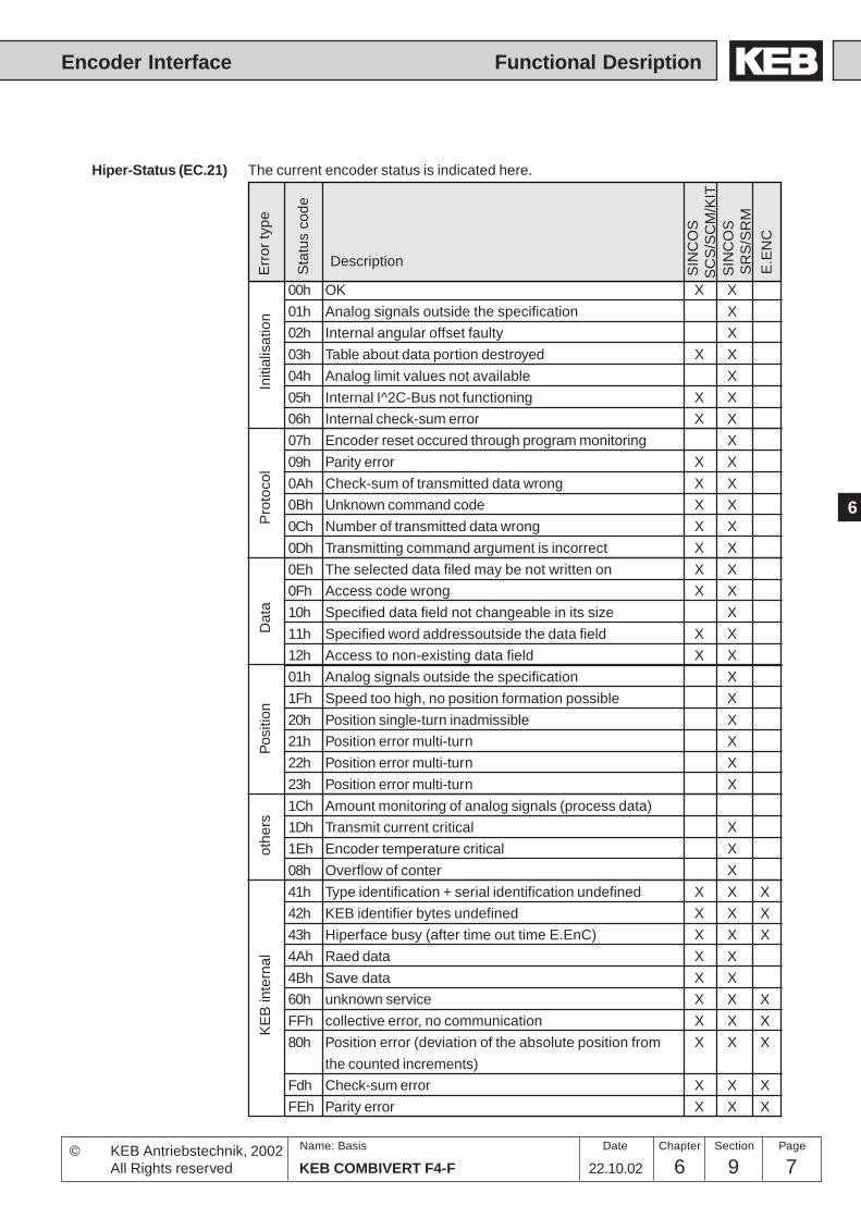
76 9 7KEB COMBIVERT F4-F
Name: Basis
22.10.02
6
Section PageDate© KEB Antriebstechnik, 2002All Rights reserved
Chapter
Functional DesriptionEncoder Interface
00h OK X X
01h Analog signals outside the specification X
02h Internal angular offset faulty X
03h Table about data portion destroyed X X
04h Analog limit values not available X
05h Internal I^2C-Bus not functioning X X
06h Internal check-sum error X X
07h Encoder reset occured through program monitoring X
09h Parity error X X
0Ah Check-sum of transmitted data wrong X X
0Bh Unknown command code X X
0Ch Number of transmitted data wrong X X
0Dh Transmitting command argument is incorrect X X
0Eh The selected data filed may be not written on X X
0Fh Access code wrong X X
10h Specified data field not changeable in its size X
11h Specified word addressoutside the data field X X
12h Access to non-existing data field X X
01h Analog signals outside the specification X
1Fh Speed too high, no position formation possible X
20h Position single-turn inadmissible X
21h Position error multi-turn X
22h Position error multi-turn X
23h Position error multi-turn X
1Ch Amount monitoring of analog signals (process data)
1Dh Transmit current critical X
1Eh Encoder temperature critical X
08h Overflow of conter X
41h Type identification + serial identification undefined X X X
42h KEB identifier bytes undefined X X X
43h Hiperface busy (after time out time E.EnC) X X X
4Ah Raed data X X
4Bh Save data X X
60h unknown service X X X
FFh collective error, no communication X X X
80h Position error (deviation of the absolute position from X X X
the counted increments)
Fdh Check-sum error X X X
FEh Parity error X X X
Hiper-Status (EC.21) The current encoder status is indicated here.
Description E
rror
type
S
tatu
s co
de
SIN
CO
S S
CS
/SC
M/K
IT S
INC
OS
S
RS
/SR
M
Ini
tialis
atio
n P
roto
col
Dat
a
Pos
ition
oth
ers
KE
B in
tern
al
E.E
NC
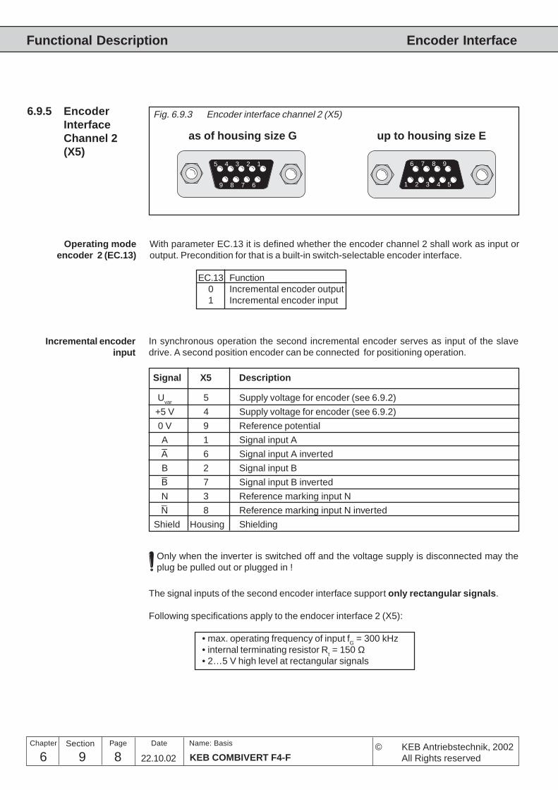
6 9 KEB COMBIVERT F4-F8Name: Basis
22.10.02
Chapter Section Page Date © KEB Antriebstechnik, 2002All Rights reserved
Functional Description Encoder Interface
Incremental encoderinput
Signal X5 Description
Uvar
5 Supply voltage for encoder (see 6.9.2)
+5 V 4 Supply voltage for encoder (see 6.9.2)
0 V 9 Reference potential
A 1 Signal input A_A 6 Signal input A inverted
B 2 Signal input B_B 7 Signal input B inverted
N 3 Reference marking input N_N 8 Reference marking input N inverted
Shield Housing Shielding
In synchronous operation the second incremental encoder serves as input of the slavedrive. A second position encoder can be connected for positioning operation.
The signal inputs of the second encoder interface support only rectangular signals.
Following specifications apply to the endocer interface 2 (X5):
• max. operating frequency of input fG
= 300 kHz• internal terminating resistor R
t= 150 Ω
• 2…5 V high level at rectangular signals
Only when the inverter is switched off and the voltage supply is disconnected may theplug be pulled out or plugged in !
6.9.5 EncoderInterfaceChannel 2(X5)
Fig. 6.9.3 Encoder interface channel 2 (X5)
as of housing size G up to housing size E
1 2 3 4 5
6 7 8 95 4 3 2 1
9 8 7 6
Operating modeencoder 2 (EC.13)
With parameter EC.13 it is defined whether the encoder channel 2 shall work as input oroutput. Precondition for that is a built-in switch-selectable encoder interface.
EC.13 Function0 Incremental encoder output1 Incremental encoder input
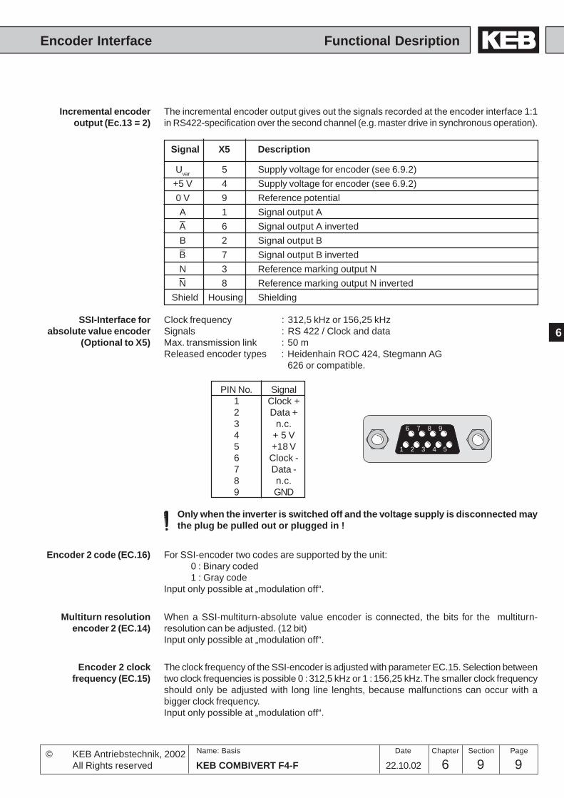
96 9 9KEB COMBIVERT F4-F
Name: Basis
22.10.02
6
Section PageDate© KEB Antriebstechnik, 2002All Rights reserved
Chapter
Functional DesriptionEncoder Interface
Encoder 2 code (EC.16) For SSI-encoder two codes are supported by the unit:0 : Binary coded1 : Gray code
Input only possible at „modulation off“.
SSI-Interface forabsolute value encoder
(Optional to X5)
Clock frequency : 312,5 kHz or 156,25 kHzSignals : RS 422 / Clock and dataMax. transmission link : 50 mReleased encoder types : Heidenhain ROC 424, Stegmann AG
626 or compatible.
PIN No. Signal1 Clock +2 Data +3 n.c.4 + 5 V5 +18 V6 Clock -7 Data -8 n.c.9 GND
1 2 3 4 5
6 7 8 9
Only when the inverter is switched off and the voltage supply is disconnected maythe plug be pulled out or plugged in !
Incremental encoderoutput (Ec.13 = 2)
Signal X5 Description
Uvar 5 Supply voltage for encoder (see 6.9.2)
+5 V 4 Supply voltage for encoder (see 6.9.2)
0 V 9 Reference potential
A 1 Signal output A_A 6 Signal output A inverted
B 2 Signal output B_B 7 Signal output B inverted
N 3 Reference marking output N_N 8 Reference marking output N inverted
Shield Housing Shielding
The incremental encoder output gives out the signals recorded at the encoder interface 1:1in RS422-specification over the second channel (e.g. master drive in synchronous operation).
When a SSI-multiturn-absolute value encoder is connected, the bits for the multiturn-resolution can be adjusted. (12 bit)Input only possible at „modulation off“.
Multiturn resolutionencoder 2 (EC.14)
Encoder 2 clockfrequency (EC.15)
The clock frequency of the SSI-encoder is adjusted with parameter EC.15. Selection betweentwo clock frequencies is possible 0 : 312,5 kHz or 1 : 156,25 kHz. The smaller clock frequencyshould only be adjusted with long line lenghts, because malfunctions can occur with abigger clock frequency.Input only possible at „modulation off“.
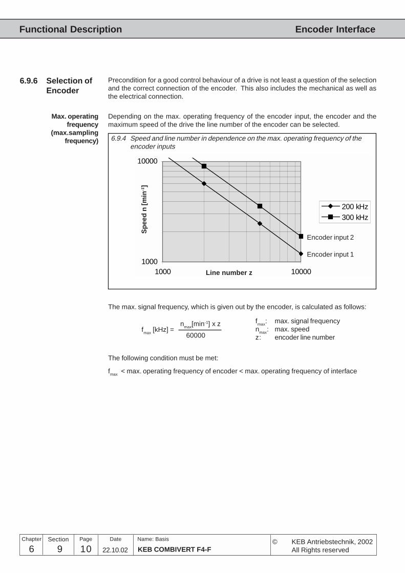
6 9 KEB COMBIVERT F4-F10Name: Basis
22.10.02
Chapter Section Page Date © KEB Antriebstechnik, 2002All Rights reserved
Functional Description Encoder Interface
The max. signal frequency, which is given out by the encoder, is calculated as follows:
nmax
[min-1] x z
60000fmax
[kHz] =fmax
: max. signal frequencyn
max: max. speed
z: encoder line number
The following condition must be met:
fmax
< max. operating frequency of encoder < max. operating frequency of interface
1000
10000
1000 10000
200 kHz300 kHz
6.9.6 Selection ofEncoder
Precondition for a good control behaviour of a drive is not least a question of the selectionand the correct connection of the encoder. This also includes the mechanical as well asthe electrical connection.
Max. operatingfrequency
(max.samplingfrequency)
Depending on the max. operating frequency of the encoder input, the encoder and themaximum speed of the drive the line number of the encoder can be selected.
6.9.4 Speed and line number in dependence on the max. operating frequency of theencoder inputs
Encoder input 2
Encoder input 1
Sp
eed
n [m
in-1]
Line number z
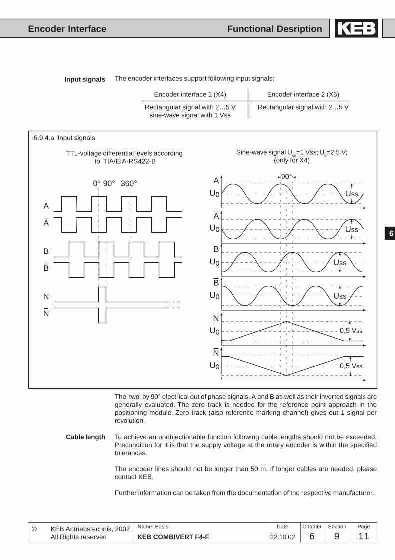
116 9 11KEB COMBIVERT F4-F
Name: Basis
22.10.02
6
Section PageDate© KEB Antriebstechnik, 2002All Rights reserved
Chapter
Functional DesriptionEncoder Interface
The encoder interfaces support following input signals:
Encoder interface 1 (X4) Encoder interface 2 (X5)
Rectangular signal with 2…5 V Rectangular signal with 2…5 Vsine-wave signal with 1 Vss
Input signals
TTL-voltage differential levels according to TIA/EIA-RS422-B
Sine-wave signal Uss
=1 Vss; U0=2,5 V;
(only for X4)
6.9.4.a Input signals
The two, by 90° electrical out of phase signals, A and B as well as their inverted signals aregenerally evaluated. The zero track is needed for the reference point approach in thepositioning module. Zero track (also reference marking channel) gives out 1 signal perrevolution.
0° 90° 360°
A
A
B
B
N
N
A
U0
AU0
B
U0
B
U0
N
U0
N
U0
90°
Uss
Uss
Uss
Uss
0,5 Vss
0,5 Vss
Cable length To achieve an unobjectionable function following cable lengths should not be exceeded.Precondition for it is that the supply voltage at the rotary encoder is within the specifiedtolerances.
The encoder lines should not be longer than 50 m. If longer cables are needed, pleasecontact KEB.
Further information can be taken from the documentation of the respective manufacturer.
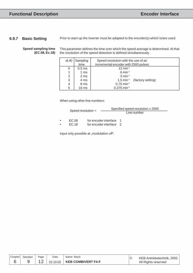
6 9 KEB COMBIVERT F4-F12Name: Basis
22.10.02
Chapter Section Page Date © KEB Antriebstechnik, 2002All Rights reserved
Functional Description Encoder Interface
This parameter defines the time over which the speed average is determined. At thatthe resolution of the speed detection is defined simultaneously.
dr.40 Sampling Speed resolution with the use of antime incremental encoder with 2500 pulses
0 0,5 ms 12 min-1
1 1 ms 6 min-1
2 2 ms 3 min-1
3 4 ms 1,5 min-1 (factory setting)4 8 ms 0,75 min-1
5 16 ms 0,375 min-1
6.9.7 Basic Setting Prior to start-up the inverter must be adapted to the encoder(s) which is/are used.
Speed sampling time(EC.08, Ec.18)
When using other line numbers:
Speed resolution =Specified speed resolution x 2500
Line number
• EC.08 for encoder interface 1• EC.18 for encoder interface 2
Input only possible at „modulation off“.
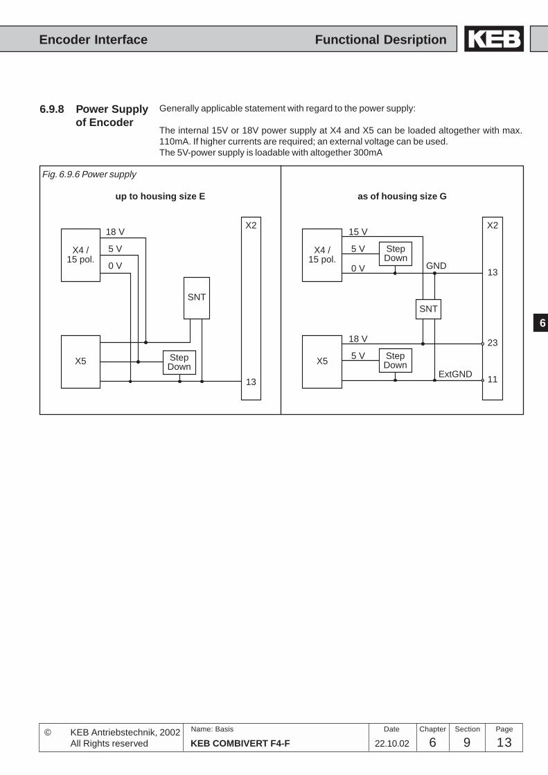
136 9 13KEB COMBIVERT F4-F
Name: Basis
22.10.02
6
Section PageDate© KEB Antriebstechnik, 2002All Rights reserved
Chapter
Functional DesriptionEncoder Interface
6.9.8 Power Supplyof Encoder
18 V
X4 /15 pol.
SNT
X2
13
StepDown
X5
5 V
0 V
15 V
X4 /15 pol.
SNT
X2
13
StepDown
X5 StepDown
ExtGND
GND
5 V
0 V
18 V
5 V23
11
Fig. 6.9.6 Power supply
up to housing size E as of housing size G
Generally applicable statement with regard to the power supply:
The internal 15V or 18V power supply at X4 and X5 can be loaded altogether with max.110mA. If higher currents are required; an external voltage can be used.The 5V-power supply is loadable with altogether 300mA
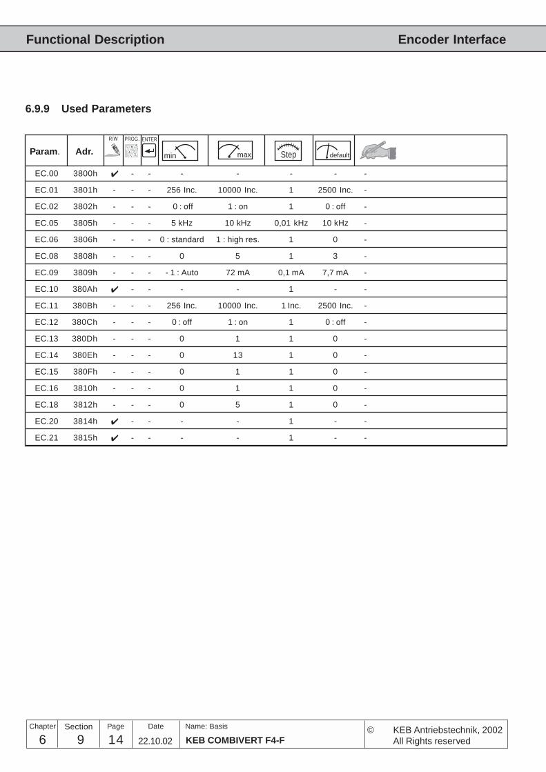
6 9 KEB COMBIVERT F4-F14Name: Basis
22.10.02
Chapter Section Page Date © KEB Antriebstechnik, 2002All Rights reserved
Functional Description Encoder Interface
EC.00 3800h - - - - - - -
EC.01 3801h - - - 256 Inc. 10000 Inc. 1 2500 Inc. -
EC.02 3802h - - - 0 : off 1 : on 1 0 : off -
EC.05 3805h - - - 5 kHz 10 kHz 0,01 kHz 10 kHz -
EC.06 3806h - - - 0 : standard 1 : high res. 1 0 -
EC.08 3808h - - - 0 5 1 3 -
EC.09 3809h - - - - 1 : Auto 72 mA 0,1 mA 7,7 mA -
EC.10 380Ah - - - - 1 - -
EC.11 380Bh - - - 256 Inc. 10000 Inc. 1 Inc. 2500 Inc. -
EC.12 380Ch - - - 0 : off 1 : on 1 0 : off -
EC.13 380Dh - - - 0 1 1 0 -
EC.14 380Eh - - - 0 13 1 0 -
EC.15 380Fh - - - 0 1 1 0 -
EC.16 3810h - - - 0 1 1 0 -
EC.18 3812h - - - 0 5 1 0 -
EC.20 3814h - - - - 1 - -
EC.21 3815h - - - - 1 - -
Param. Adr. min max default
ENTERPROG.R/W
Step
6.9.9 Used Parameters
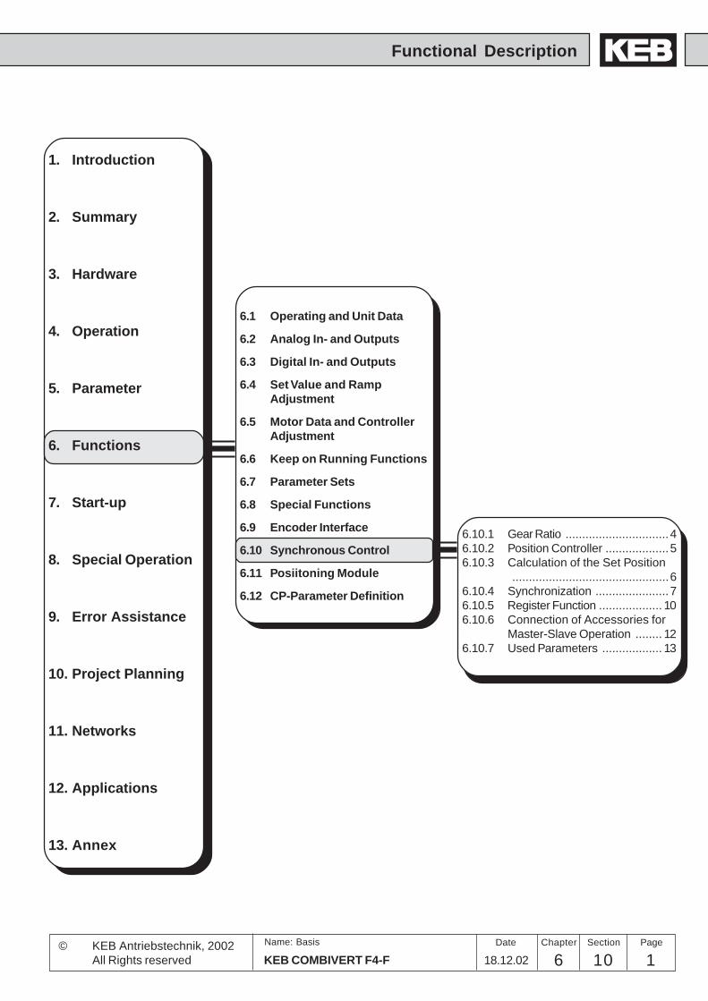
6 10 1KEB COMBIVERT F4-F
Name: Basis
18.12.02
Functional Description
Chapter Section PageDate© KEB Antriebstechnik, 2002All Rights reserved
1. Introduction
2. Summary
3. Hardware
4. Operation
5. Parameter
6. Functions
7. Start-up
8. Special Operation
9. Error Assistance
10. Project Planning
11. Networks
12. Applications
13. Annex
6.1 Operating and Unit Data
6.2 Analog In- and Outputs
6.3 Digital In- and Outputs
6.4 Set Value and RampAdjustment
6.5 Motor Data and ControllerAdjustment
6.6 Keep on Running Functions
6.7 Parameter Sets
6.8 Special Functions
6.9 Encoder Interface
6.10 Synchronous Control
6.11 Posiitoning Module
6.12 CP-Parameter Definition
6.10.1 Gear Ratio ...............................46.10.2 Position Controller ...................56.10.3 Calculation of the Set Position
...............................................66.10.4 Synchronization ......................76.10.5 Register Function ................... 106.10.6 Connection of Accessories for
Master-Slave Operation ........ 126.10.7 Used Parameters .................. 13

6 10 KEB COMBIVERT F4-F2Name: Basis
18.12.02
Chapter Section Page Date © KEB Antriebstechnik, 2002All Rights reserved
Functional Description Sychronous Control
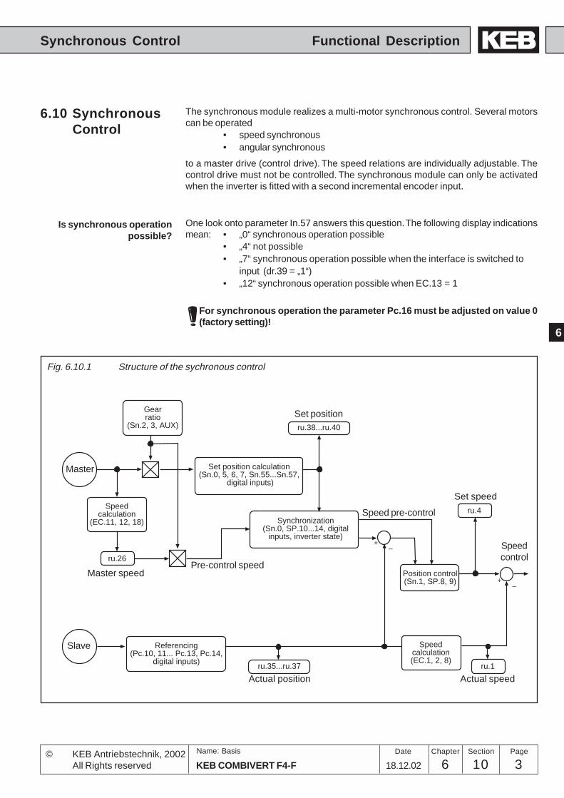
36 10 3KEB COMBIVERT F4-F
Name: Basis
18.12.02
6
Section PageDate© KEB Antriebstechnik, 2002All Rights reserved
Chapter
Functional DescriptionSynchronous Control
6.10 SynchronousControl
The synchronous module realizes a multi-motor synchronous control. Several motorscan be operated
• speed synchronous• angular synchronous
to a master drive (control drive). The speed relations are individually adjustable. Thecontrol drive must not be controlled. The synchronous module can only be activatedwhen the inverter is fitted with a second incremental encoder input.
Is synchronous operationpossible?
One look onto parameter In.57 answers this question. The following display indicationsmean: • „0“ synchronous operation possible
• „4“ not possible• „7“ synchronous operation possible when the interface is switched to
input (dr.39 = „1“)• „12“ synchronous operation possible when EC.13 = 1
+
Speedcalculation
(EC.11, 12, 18)
Set position calculation(Sn.0, 5, 6, 7, Sn.55...Sn.57,
digital inputs)
ru.26
ru.38...ru.40
Synchronization(Sn.0, SP.10...14, digital
inputs, inverter state)
Gearratio
(Sn.2, 3, AUX)
Speedcalculation(EC.1, 2, 8)
Referencing(Pc.10, 11... Pc.13, Pc.14,
digital inputs)ru.35...ru.37 ru.1
Position control(Sn.1, SP.8, 9)
ru.4
–
+–
Slave
Master
Fig. 6.10.1 Structure of the sychronous control
Speed pre-control
Pre-control speedMaster speed
Set speed
Actual speed
Set position
Actual position
Speedcontrol
For synchronous operation the parameter Pc.16 must be adjusted on value 0(factory setting)!
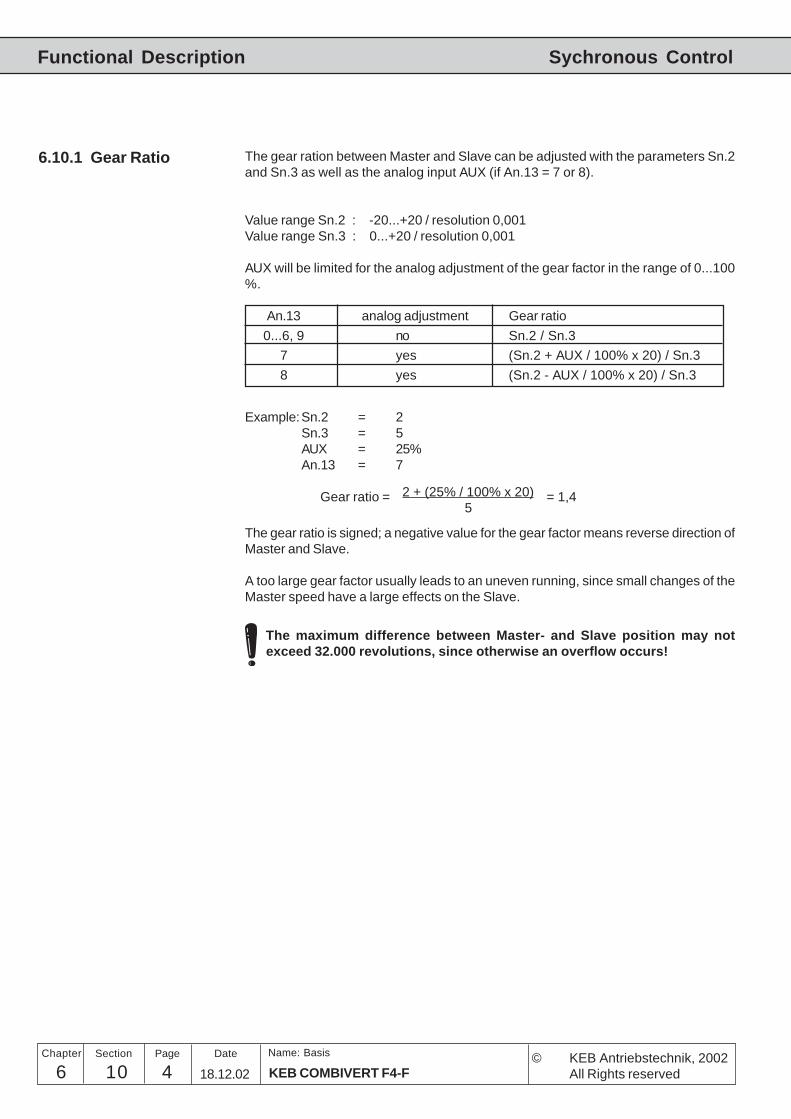
6 10 KEB COMBIVERT F4-F4Name: Basis
18.12.02
Chapter Section Page Date © KEB Antriebstechnik, 2002All Rights reserved
Functional Description Sychronous Control
The gear ration between Master and Slave can be adjusted with the parameters Sn.2and Sn.3 as well as the analog input AUX (if An.13 = 7 or 8).
Value range Sn.2 : -20...+20 / resolution 0,001Value range Sn.3 : 0...+20 / resolution 0,001
AUX will be limited for the analog adjustment of the gear factor in the range of 0...100%.
An.13 analog adjustment Gear ratio
0...6, 9 no Sn.2 / Sn.3
7 yes (Sn.2 + AUX / 100% x 20) / Sn.3
8 yes (Sn.2 - AUX / 100% x 20) / Sn.3
6.10.1 Gear Ratio
Example:Sn.2 = 2Sn.3 = 5AUX = 25%An.13 = 7
Gear ratio = = 1,42 + (25% / 100% x 20)5
The gear ratio is signed; a negative value for the gear factor means reverse direction ofMaster and Slave.
A too large gear factor usually leads to an uneven running, since small changes of theMaster speed have a large effects on the Slave.
The maximum difference between Master- and Slave position may notexceed 32.000 revolutions, since otherwise an overflow occurs!
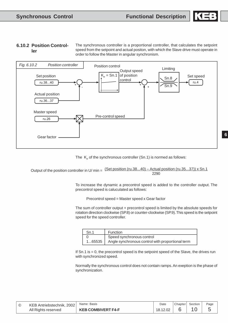
56 10 5KEB COMBIVERT F4-F
Name: Basis
18.12.02
6
Section PageDate© KEB Antriebstechnik, 2002All Rights reserved
Chapter
Functional DescriptionSynchronous Control
6.10.2 Position Control-ler
Fig. 6.10.2 Position controller
KP = Sn.1
Sn.8
Sn.9
Position controlLimiting
Pre-control speed
Set position
Actual position
Master speed
Gear factor
Set speedOutput speedof positioncontrol
The KP of the synchronous controller (Sn.1) is normed as follows:
To increase the dynamic a precontrol speed is added to the controller output. Theprecontrol speed is caluculated as follows:
Precontrol speed = Master speed x Gear factor
The sum of controller output + precontrol speed is limited by the absolute speeds forrotation direction clockwise (SP.8) or counter-clockwise (SP.9). This speed is the setpointspeed for the speed controller.
(Set position (ru.38...40) – Actual position (ru.35...37)) x Sn.12290
Output of the position controller in U/ min =
The synchronous controller is a proportional controller, that calculates the setpointspeed from the setpoint and actual positon, with which the Slave drive must operate inorder to follow the Master in angular synchronism.
Sn.1 Function0 Speed synchronous control1...65535 Angle synchronous control with proportional term
If Sn.1 is = 0, the precontrol speed is the setpoint speed of the Slave, the drives runwith synchronized speed.
Normally the synchronous control does not contain ramps. An exeption is the phase ofsynchronization.
6 10 KEB COMBIVERT F4-F6Name: Basis
18.12.02
Chapter Section Page Date © KEB Antriebstechnik, 2002All Rights reserved
Functional Description Sychronous Control
6.10.3 Calculation of theSet Position
Calculation of the StartingPosition
The synchronous module is deactivated at: Sn.0 = 0or Pc.0 = 1
or if an input with the input function 9 (synchronous controller ‘off’) is active.
If the synchronous mode is activated, the start value of the set position calculates independence of parameter Sn.0.
Sn.0 Starting value of the set position
1 Set position = Actual position
2,3 see Register function (6.10.6)
4 Set position = Actual position – Startoffset (Sn.55...57)
5 Set position = reference point position – Startoffset (Sn.55...57) *1
Calculation of the Position inSynchronous Operation
During synchronous is active , the set position is calculated as follows:(Exception sychronization / Chapter 6.10.4)
Set position = Starting value + Gear factor x Variation of the Master position *1
*1 since activating the synchronous operation
The setpoint position can be changed by the functions ‘Resetting angular difference’(digital input function 6), ‘Angular shifting positive’ (digital input function 7 or Sn.5 = 1)and ‘Angular shifting negative’ (digital input function 8 or Sn.5 = 2).
resetting angular difference: Set position = Actual positionAngular shifting positive: Set position new = Set position old + Sn.6, 7Angular shifting negative: Set position new = Set position old – Sn.6, 7
Value range Sn.6 : 0...360° resolution 0,1°Value range Sn.7 : 0...10.000 U/ min resolution 1 U/ min
Angular shifting = Sn.7 x 360° + Sn.6
Sn.5 Function0 no correcture1 correcture in positive direction2 correcture in negative directon
*1 To be able to use this function a reference point run is always necessary afterPower-On, since otherwise the drive behaves as with Sn.0 = 1.
Resetting angular difference An angular difference between Master and Slave can be reset by the following measures:
• writing on parameter Sn.0• setting digital input (deactivate synchronous control = value „9“)• setting digital input (resetting angular deviation = value „6“)
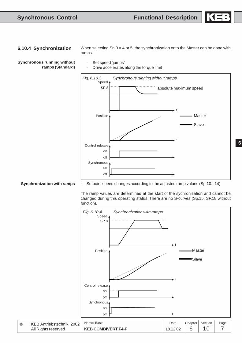
76 10 7KEB COMBIVERT F4-F
Name: Basis
18.12.02
6
Section PageDate© KEB Antriebstechnik, 2002All Rights reserved
Chapter
Functional DescriptionSynchronous Control
Synchronization with ramps - Setpoint speed changes according to the adjusted ramp values (Sp.10...14)
The ramp values are determined at the start of the sychronization and cannot bechanged during this operating status. There are no S-curves (Sp.15, SP.18 withoutfunction).
6.10.4 Synchronization When selecting Sn.0 = 4 or 5, the synchronization onto the Master can be done withramps.
- Set speed ‘jumps’- Drive accelerates along the torque limit
Synchronous running withoutramps (Standard)
t
SP.8
Speed
t
Position
Control release
off
on
Synchronous
off
on
absolute maximum speed
Fig. 6.10.3 Synchronous running without ramps
Master
Slave
t
SP.8Speed
t
Position
Control release
off
on
Synchronous
off
on
Fig. 6.10.4 Synchronization with ramps
Master
Slave
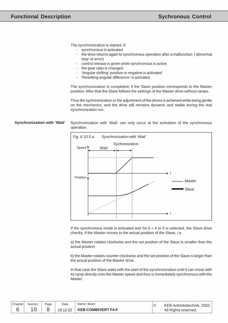
6 10 KEB COMBIVERT F4-F8Name: Basis
18.12.02
Chapter Section Page Date © KEB Antriebstechnik, 2002All Rights reserved
Functional Description Sychronous Control
The synchronization is started, if:- synchronous is activated- the drive returns again to synchronous operation after a malfunction (‘abnormal
stop’ or error)- control release is given while synchronous is active- the gear ratio is changed- ‘Angular shifting’ positive or negative is activated- ‘Resetting angular difference’ is activated
The synchronization is completed, if the Slave position corresponds to the Masterposition. After that the Slave follows the settings of the Master drive without ramps.
Thus the sychnronization or the adjustment of the drives is achieved while being gentleon the mechanics, and the drive still remains dynamic and stable during the realsynchronization run.
Synchronization with ‘Wait’ Synchronization with ‘Wait’ can only occur at the activation of the synchronousoperation.
If the synchronous mode is activated and Sn.0 = 4 or 5 is selected, the Slave drivechecks, if the Master moves to the actual position of the Slave, i.e.
a) the Master rotates clockwise and the set position of the Slave is smaller than theactual position
b) the Master rotates counter-clockwise and the set position of the Slave is larger thanthe actual position of the Master drive.
In that case the Slave waits with the start of the synchronization until it can move withits ramp directly onto the Master speed and thus is immediately synchronous with theMaster.
t
Speed
t
Position
Fig. 6.10.5.a Synchronization with ‘Wait’
Master
Slave
WaitSychronization
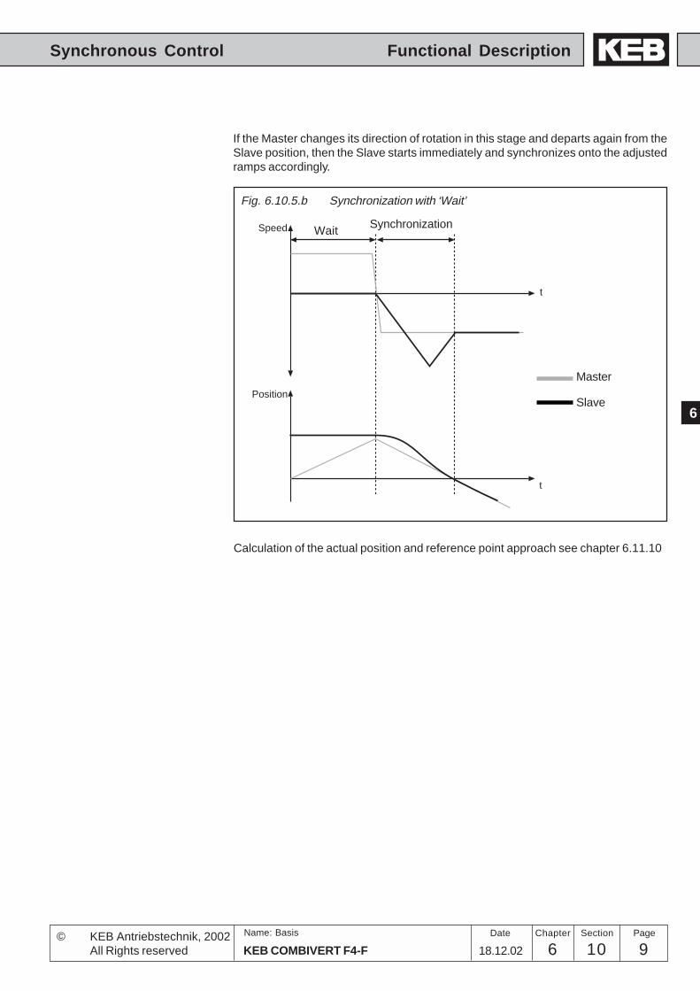
96 10 9KEB COMBIVERT F4-F
Name: Basis
18.12.02
6
Section PageDate© KEB Antriebstechnik, 2002All Rights reserved
Chapter
Functional DescriptionSynchronous Control
If the Master changes its direction of rotation in this stage and departs again from theSlave position, then the Slave starts immediately and synchronizes onto the adjustedramps accordingly.
t
Speed
t
Position
Fig. 6.10.5.b Synchronization with ‘Wait’
Master
Slave
Wait Synchronization
Calculation of the actual position and reference point approach see chapter 6.11.10
6 10 KEB COMBIVERT F4-F10Name: Basis
18.12.02
Chapter Section Page Date © KEB Antriebstechnik, 2002All Rights reserved
Functional Description Sychronous Control
6.10.5 Register Function In synchronous operationthe possibility exists to synchronize Master and Slaveadditionally onto two reference signals. These reference signals are found for exampleat the master axis and the slave axis in form of proxibility sensors. Through the registerfunction the gear factor and the angular connection can then be activated until bothreference signals are synchronized.The ramps (only SP.11...SP.12) adjusted in the SP-parameters are active. Changes ofthe ramp values while the register function is active are not accepted. Acceptance ofthe ramp values only at start-register function.
The register function is activated by:
Sn.0 = 2 Register function ONdi.03 = off Input 1 always ha sthe function of the master signaldi.04 = off Input 2 always has the function of the slave signaldi.05 = 9 Synchronous off
After the actiation of the register function both initiator signals must come two timesbefore the rgister function triggers an action.
If switching into a parameter set with Sn.00 = 3, the first calculated angular offsetbetween master and slave is stored in Sn.30...Sn.32 (teach).
Register function period(Sn.08)
With this parameter the value is adjusted, by which the gear factor can change duringa measuring period. A Measuring period means, that a psitive edge was recognized atboth reference signals. The changed gear factor remains permanently stored in Sn.02.If the gear factor can not changed during a process, the value 0 should be pre-set inSn.08. In that case only the angle is corrected.
Register function filter mode(Sn.21)
This mode is used for the suppression of interference signals at the two initiatorsignals.
Sn.21 Function0 off1 Master strobe: After a master signal only the next edge of the slave
signal is used. Further slave signals are ignored.2 Slave strobe: After a slave signal only the next edge of the slave
signal is used. Further master signals are ignored.
Register function correctionmode (Sn.25)
With this parameter the direction of the angular correction can be selected. In order toachieve a stable operation with only one direction of correction, the gear factor shouldbe adjusted a little, so that the angular correction is always possible with one directiononly.
116 10 11KEB COMBIVERT F4-F
Name: Basis
18.12.02
6
Section PageDate© KEB Antriebstechnik, 2002All Rights reserved
Chapter
Functional DescriptionSynchronous Control
Period level for angularcorrection (Sn.22...Sn.24)
The angular correction can be suppressed with this parameter, as long as the deviationof the perio is too large. So long as the value displayed in Sn.46...Sn.48 is larger thanSn.22...Sn.24, no angular correction is carried out.
Maximal value for angularcorrection (Sn.26...Sn.28)
The angular correction is not carried out, if the amount of the value displayed inSn.49...Sn.51 is larger than this parameter.
Maximal angular correction(Sn.52...Sn.54)
The angle, which can be corrected maximally in one measuring period, is specifiedhere. The value corresponds to one revolution of the motor. The angular correction canonly operate, if a P-component is adjusted in Sn.01.
Angular offset (Sn.29...Sn.36) The setpoint value of the angular offset between master and slave signal is pre-set inthese parameters. The angular offset can be pre-set as constant (Sn.33 = 0) or linearlyinterpolated in a speed range. if the anglua offset is determined with the teach-function,the value is always written in Sn.29...Sn.31.
Slave ratio (Sn.20) With active register function the ratio of master signal to slave signal can be adjustedhere.
Slave register display(Sn.40...Sn.42)
These parameters display the distance travelled by the slave between two signals ofinput 2. One revolution of the slave corresponds to a value of 65535. This register isupdated with every signal at I2.
Master register display(Sn.43...Sn.45)
These parameters display the distance travelled by the master between two signals ofinput 1. One revolution of the master encoder with the line number adjusted in EC.11corresponds to a value of 65535. This value, multiplied by the gear factor Sn.02, isdisplayed in the master register. This signal is updated with every signal at I1.
Period display(Sn.46...Sn.48)
After master and slave register are written, the difference between these two values isrepresented in the period display. This calculation is triggered, if master signal andslave signal have been idetified. After the initialization master signal and slave signalmust each be identified two times. If the gear factor has been adjusted by the registerfunction onto the suitable value, the period display shows approximately zero.
Period display(Sn.46...Sn.48)
This register is calculated simultaneously with the period display. The path of theslave between master signal and slave signal is displayed.
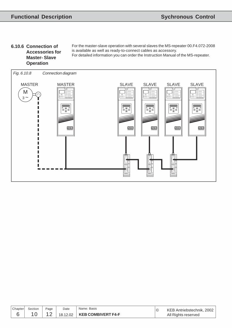
6 10 KEB COMBIVERT F4-F12Name: Basis
18.12.02
Chapter Section Page Date © KEB Antriebstechnik, 2002All Rights reserved
Functional Description Sychronous Control
For the master-slave operation with several slaves the MS-repeater 00.F4.072-2008is available as well as ready-to-connect cables as accessory.For detailed information you can order the Instruction Manual of the MS-repeater.
6.10.6 Connection ofAccessories forMaster- SlaveOperation
12
34
5
67
89
54
32
1
98
76
12
34
5
67
89
54
32
1
98
76
12
34
5
67
89
54
32
1
98
76
STAR
STOP
FUNC.
SPEED
ENTER
F/R
ANTRIEBSTECHNIK
POWER XXXXXXXXXXXX
INPUT
OUTPUT
KEB AntriebstechnikKarl E. Brinkmann GmbHD-32677 Barntrup
Made in Germany
VOLTAGECYCLE
XXXXXXXXXXXXXXXXXXXXXX
VOLTAGECURRENT
VER-NO.ART-NO.SER-NO.
XXXXXXXXXXXXXXX˜
95000001/XXXXXXXXX.F4.XXX-XXXX
XXXXXXXXXXXXXXXXXXXXXX
AC-MOT. 4,0 KW, 2/4 P, 50/60 HZ
MASTER SLAVE SLAVE SLAVE SLAVE
M3 ~
MASTER
Fig. 6.10.8 Connection diagram
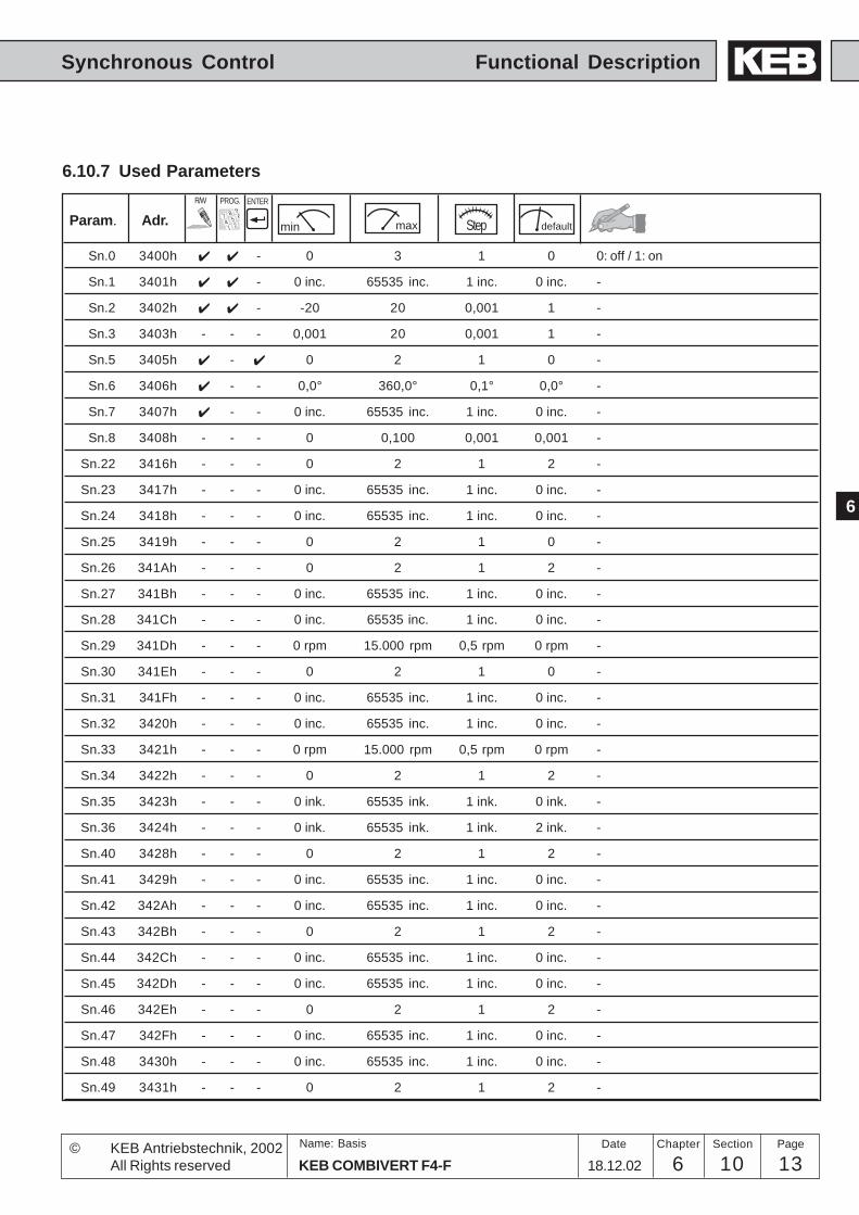
136 10 13KEB COMBIVERT F4-F
Name: Basis
18.12.02
6
Section PageDate© KEB Antriebstechnik, 2002All Rights reserved
Chapter
Functional DescriptionSynchronous Control
Param. Adr. min max default
ENTERPROG.R/W
Step
Sn.0 3400h - 0 3 1 0 0: off / 1: on
Sn.1 3401h - 0 inc. 65535 inc. 1 inc. 0 inc. -
Sn.2 3402h - -20 20 0,001 1 -
Sn.3 3403h - - - 0,001 20 0,001 1 -
Sn.5 3405h - 0 2 1 0 -
Sn.6 3406h - - 0,0° 360,0° 0,1° 0,0° -
Sn.7 3407h - - 0 inc. 65535 inc. 1 inc. 0 inc. -
Sn.8 3408h - - - 0 0,100 0,001 0,001 -
Sn.22 3416h - - - 0 2 1 2 -
Sn.23 3417h - - - 0 inc. 65535 inc. 1 inc. 0 inc. -
Sn.24 3418h - - - 0 inc. 65535 inc. 1 inc. 0 inc. -
Sn.25 3419h - - - 0 2 1 0 -
Sn.26 341Ah - - - 0 2 1 2 -
Sn.27 341Bh - - - 0 inc. 65535 inc. 1 inc. 0 inc. -
Sn.28 341Ch - - - 0 inc. 65535 inc. 1 inc. 0 inc. -
Sn.29 341Dh - - - 0 rpm 15.000 rpm 0,5 rpm 0 rpm -
Sn.30 341Eh - - - 0 2 1 0 -
Sn.31 341Fh - - - 0 inc. 65535 inc. 1 inc. 0 inc. -
Sn.32 3420h - - - 0 inc. 65535 inc. 1 inc. 0 inc. -
Sn.33 3421h - - - 0 rpm 15.000 rpm 0,5 rpm 0 rpm -
Sn.34 3422h - - - 0 2 1 2 -
Sn.35 3423h - - - 0 ink. 65535 ink. 1 ink. 0 ink. -
Sn.36 3424h - - - 0 ink. 65535 ink. 1 ink. 2 ink. -
Sn.40 3428h - - - 0 2 1 2 -
Sn.41 3429h - - - 0 inc. 65535 inc. 1 inc. 0 inc. -
Sn.42 342Ah - - - 0 inc. 65535 inc. 1 inc. 0 inc. -
Sn.43 342Bh - - - 0 2 1 2 -
Sn.44 342Ch - - - 0 inc. 65535 inc. 1 inc. 0 inc. -
Sn.45 342Dh - - - 0 inc. 65535 inc. 1 inc. 0 inc. -
Sn.46 342Eh - - - 0 2 1 2 -
Sn.47 342Fh - - - 0 inc. 65535 inc. 1 inc. 0 inc. -
Sn.48 3430h - - - 0 inc. 65535 inc. 1 inc. 0 inc. -
Sn.49 3431h - - - 0 2 1 2 -
6.10.7 Used Parameters
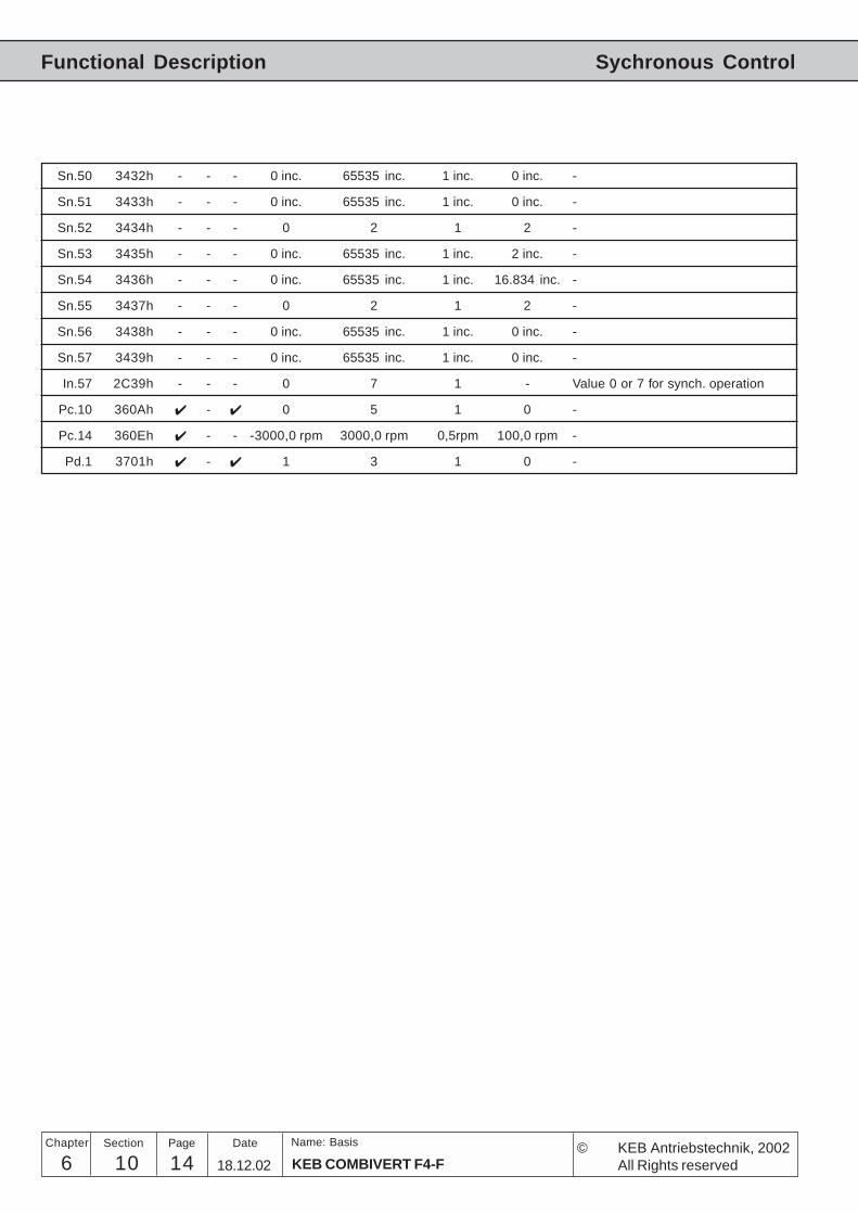
6 10 KEB COMBIVERT F4-F14Name: Basis
18.12.02
Chapter Section Page Date © KEB Antriebstechnik, 2002All Rights reserved
Functional Description Sychronous Control
Sn.50 3432h - - - 0 inc. 65535 inc. 1 inc. 0 inc. -
Sn.51 3433h - - - 0 inc. 65535 inc. 1 inc. 0 inc. -
Sn.52 3434h - - - 0 2 1 2 -
Sn.53 3435h - - - 0 inc. 65535 inc. 1 inc. 2 inc. -
Sn.54 3436h - - - 0 inc. 65535 inc. 1 inc. 16.834 inc. -
Sn.55 3437h - - - 0 2 1 2 -
Sn.56 3438h - - - 0 inc. 65535 inc. 1 inc. 0 inc. -
Sn.57 3439h - - - 0 inc. 65535 inc. 1 inc. 0 inc. -
In.57 2C39h - - - 0 7 1 - Value 0 or 7 for synch. operation
Pc.10 360Ah - 0 5 1 0 -
Pc.14 360Eh - - -3000,0 rpm 3000,0 rpm 0,5rpm 100,0 rpm -
Pd.1 3701h - 1 3 1 0 -
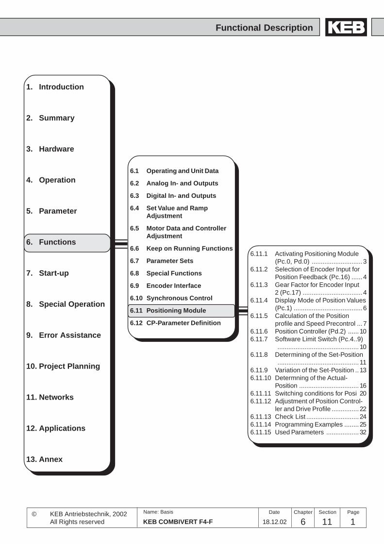
6 11 1KEB COMBIVERT F4-F
Name: Basis
18.12.02
Functional Description
Chapter Section PageDate© KEB Antriebstechnik, 2002All Rights reserved
1. Introduction
2. Summary
3. Hardware
4. Operation
5. Parameter
6. Functions
7. Start-up
8. Special Operation
9. Error Assistance
10. Project Planning
11. Networks
12. Applications
13. Annex
6.1 Operating and Unit Data
6.2 Analog In- and Outputs
6.3 Digital In- and Outputs
6.4 Set Value and RampAdjustment
6.5 Motor Data and ControllerAdjustment
6.6 Keep on Running Functions
6.7 Parameter Sets
6.8 Special Functions
6.9 Encoder Interface
6.10 Synchronous Control
6.11 Positioning Module
6.12 CP-Parameter Definition
6.11.1 Activating Positioning Module(Pc.0, Pd.0) ............................3
6.11.2 Selection of Encoder Input forPosition Feedback (Pc.16) ......4
6.11.3 Gear Factor for Encoder Input2 (Pc.17) .................................4
6.11.4 Display Mode of Position Values(Pc.1) ......................................6
6.11.5 Calculation of the Positionprofile and Speed Precontrol ...7
6.11.6 Position Controller (Pd.2) ...... 106.11.7 Software Limit Switch (Pc.4..9)
............................................. 106.11.8 Determining of the Set-Position
............................................. 116.11.9 Variation of the Set-Position .. 136.11.10 Determning of the Actual-
Position ................................. 166.11.11 Switching conditions for Posi 206.11.12 Adjustment of Position Control-
ler and Drive Profile ............... 226.11.13 Check List ............................. 246.11.14 Programming Examples ........ 256.11.15 Used Parameters .................. 32

6 11 KEB COMBIVERT F4-F2Name: Basis
18.12.02
Chapter Section Page Date © KEB Antriebstechnik, 2002All Rights reserved
Functional Description Positioning Module
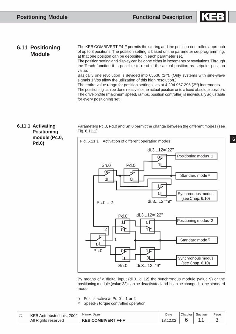
36 11 3KEB COMBIVERT F4-F
Name: Basis
18.12.02
6
Section PageDate© KEB Antriebstechnik, 2002All Rights reserved
Chapter
Functional DescriptionPositioning Module
Pc.0
Sn.0
Pd.0
di.3...12="9"
di.3...12="22"
0
0
1
10
0
1
1
0
0
1 0
Sn.0 Pd.0
0
1
1
0
di.3...12="22"
di.3...12="9"Pc.0 = 2
2
1
1
6.11 PositioningModule
6.11.1 ActivatingPositioningmodule (Pc.0,Pd.0)
The KEB COMBIVERT F4-F permits the storing and the position-controlled approachof up to 8 positions. The position setting is based on the parameter set programming,at that one position can be deposited in each parameter set.The position setting and display can be done either in increments or revolutions. Throughthe Teach-function it is possible to read-in the actual position as setpoint positionvalue.Basically one revolution is devided into 65536 (216). (Only systems with sine-wavesignals 1 Vss allow the utilization of this high resolution.)The entire value range for position settings lies at 4.294.967.296 (232) increments.The positioning can be done relative to the actual position or to a fixed absolute position.The drive profile (maximum speed, ramps, position controller) is individually adjustablefor every positioning set.
Parameters Pc.0, Pd.0 and Sn.0 permit the change between the different modes (seeFig. 6.11.1).
Synchronous modus(see Chap. 6.10)
Standard mode 1)
Positioning modus 1
Fig. 6.11.1 Activation of different operating modes
By means of a digital input (di.3...di.12) the synchronous module (value 9) or thepositioning module (value 22) can be deactivated and it can be changed to the standardmode.
Synchronous modus(see Chap. 6.10)
Standard mode 1)
Positioning modus 2
*) Posi is active at Pd.0 = 1 or 21) Speed- / torque controlled operation
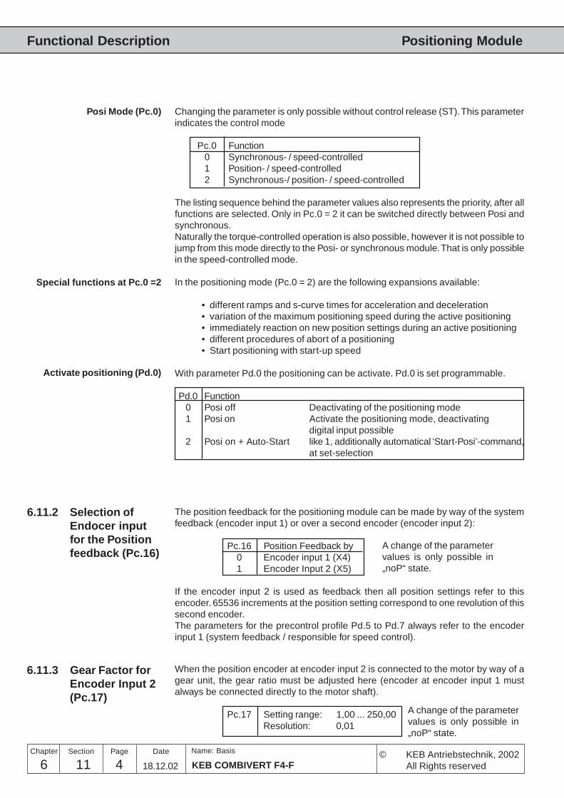
6 11 KEB COMBIVERT F4-F4Name: Basis
18.12.02
Chapter Section Page Date © KEB Antriebstechnik, 2002All Rights reserved
Functional Description Positioning Module
Posi Mode (Pc.0) Changing the parameter is only possible without control release (ST). This parameterindicates the control mode
Pc.0 Function0 Synchronous- / speed-controlled1 Position- / speed-controlled2 Synchronous-/ position- / speed-controlled
The listing sequence behind the parameter values also represents the priority, after allfunctions are selected. Only in Pc.0 = 2 it can be switched directly between Posi andsynchronous.Naturally the torque-controlled operation is also possible, however it is not possible tojump from this mode directly to the Posi- or synchronous module. That is only possiblein the speed-controlled mode.
In the positioning mode (Pc.0 = 2) are the following expansions available:
• different ramps and s-curve times for acceleration and deceleration• variation of the maximum positioning speed during the active positioning• immediately reaction on new position settings during an active positioning• different procedures of abort of a positioning• Start positioning with start-up speed
With parameter Pd.0 the positioning can be activate. Pd.0 is set programmable.
Pd.0 Function0 Posi off Deactivating of the positioning mode1 Posi on Activate the positioning mode, deactivating
digital input possible2 Posi on + Auto-Start like 1, additionally automatical ‘Start-Posi’-command,
at set-selection
Special functions at Pc.0 =2
Activate positioning (Pd.0)
The position feedback for the positioning module can be made by way of the systemfeedback (encoder input 1) or over a second encoder (encoder input 2):
Pc.16 Position Feedback by0 Encoder input 1 (X4)1 Encoder Input 2 (X5)
If the encoder input 2 is used as feedback then all position settings refer to thisencoder. 65536 increments at the position setting correspond to one revolution of thissecond encoder.The parameters for the precontrol profile Pd.5 to Pd.7 always refer to the encoderinput 1 (system feedback / responsible for speed control).
A change of the parametervalues is only possible in„noP“ state.
6.11.2 Selection ofEndocer inputfor the Positionfeedback (Pc.16)
6.11.3 Gear Factor forEncoder Input 2(Pc.17)
When the position encoder at encoder input 2 is connected to the motor by way of agear unit, the gear ratio must be adjusted here (encoder at encoder input 1 mustalways be connected directly to the motor shaft).
Pc.17 Setting range: 1,00 ... 250,00Resolution: 0,01
A change of the parametervalues is only possible in„noP“ state.
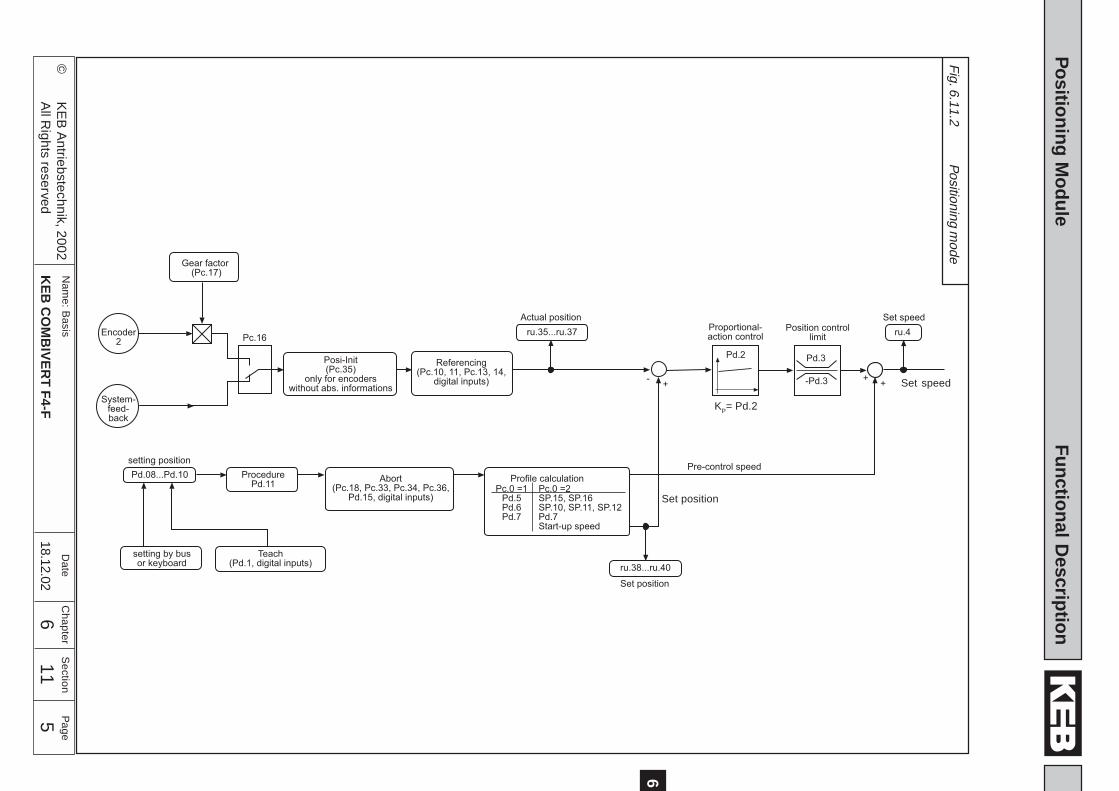
56
115
KE
B C
OM
BIV
ER
T F
4-F
Nam
e: Basis
18.12.02
6
Section
Page
Date
©K
EB
Antriebstechnik, 2002
All R
ights reserved
Chapter
Fu
nctio
nal D
escriptio
nP
ositio
nin
g M
od
ule
!
"# $%& '
( )****
)" +
!
,"+
,& ****
!*)" +
)+
-%*)" +
)&#&.#&
""" !
/!*//*/*//++
/+
"+
+ " "
""'
/+
0
/#'&.
Set speed
Fig. 6.11.2
Positioning m
ode
Set position
KP= Pd.2
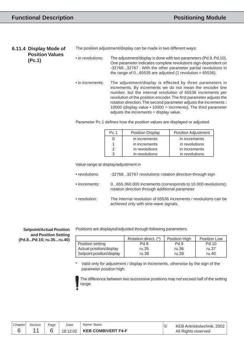
6 11 KEB COMBIVERT F4-F6Name: Basis
18.12.02
Chapter Section Page Date © KEB Antriebstechnik, 2002All Rights reserved
Functional Description Positioning Module
6.11.4 Display Mode ofPosition Values(Pc.1)
The position adjustment/display can be made in two different ways:
• in revolutions: The adjustment/display is done with two parameters (Pd.9, Pd.10).One parameter indicates complete revolutions sign-dependent on-32768...32767 . With the other parameter partial revolutions inthe range of 0...65535 are adjusted (1 revolution = 65536).
• in increments: The adjustment/display is effected by three parameters inincrements. By increments we do not mean the encoder linenumber, but the internal resolution of 65536 increments perrevolution of the position encoder. The first parameter adjusts therotation direction. The second parameter adjusts the increments :10000 (display value • 10000 = incrments). The third parameteradjusts the increments = display value.
Parameter Pc.1 defines how the position values are displayed or adjusted.
Pc.1 Position Display Position Adjustment
0 in increments in increments1 in increments in revolutions2 in revolutions in increments3 in revolutions in revolutions
Setpoint/Actual Positionand Position Setting
(Pd.8...Pd.10; ru.35...ru.40)
Positions are displayed/adjusted through following parameters:
Rotation direct. (*) Position High Position LowPosition setting Pd.8 Pd.9 Pd.10Actual position/display ru.35 ru.36 ru.37Setpoint position/display ru.38 ru.39 ru.40
* Valid only for adjustment / display in increments, otherwise by the sign of theparameter position high.
The difference between two successive positions may not exceed half of the settingrange.
Value range at display/adjustment in
• revolutions: -32768...32767 revolutions; rotation direction through sign
• increments: 0...655.360.000 increments (corresponds to 10.000 revolutions);rotation direction through additional parameter
• resolution: The internal resolution of 65536 increments / revolutions can beachieved only with sine-wave signals.
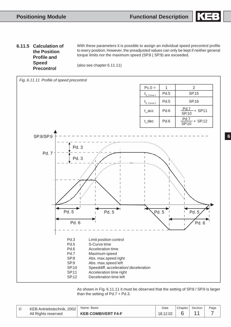
76 11 7KEB COMBIVERT F4-F
Name: Basis
18.12.02
6
Section PageDate© KEB Antriebstechnik, 2002All Rights reserved
Chapter
Functional DescriptionPositioning Module
!
! ! !
/ 1/2
Fig. 6.11.11 Profile of speed precontrol
With these parameters it is possible to assign an individual speed precontrol profileto every position. However, the preadjusted values can only be kept if neither generaltorque limits nor the maximum speed (SP.8 ( SP.9) are exceeded.
As shown in Fig. 6.11.11 it must be observed that the setting of SP.8 / SP.9 is largerthan the setting of Pd.7 + Pd.3.
Pc.0 = 1 2
tS_Curve 1
Pd.5 SP.15
tS_Curve 2 Pd.5 SP.16
t_acc Pd.6 • SP11
t_dec Pd.6 • SP.12Pd.7SP.10
Pd.7SP.10
Pd.3 Limit position controlPd.5 S-Curve timePd.6 Acceleration timePd.7 Maximum speedSP.8 Abs. max.speed rightSP.9 Abs. max.speed leftSP.10 Speeddiff. acceleration/ decelerationSP.11 Acceleration time rightSP.12 Deceleration time left
6.11.5 Calculation ofthe PositionProfile andSpeedPrecontrol
(also see chapter 6.11.11)
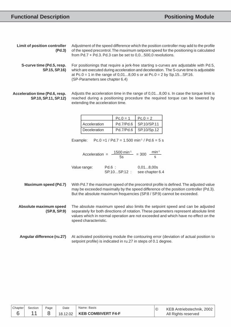
6 11 KEB COMBIVERT F4-F8Name: Basis
18.12.02
Chapter Section Page Date © KEB Antriebstechnik, 2002All Rights reserved
Functional Description Positioning Module
Limit of position controller(Pd.3)
Adjustment of the speed difference which the position controller may add to the profileof the speed precontrol. The maximum setpoint speed for the positioning is calculatedfrom Pd.7 + Pd.3. Pd.3 can be set to 0,0...500,0 revolutions.
S-curve time (Pd.5, resp.SP.15, SP.16)
For positionings that require a jerk-free starting s-curves are adjustable with Pd.5,which are executed during acceleration and deceleration. The S-curve time is adjustableat Pc.0 = 1 in the range of 0,01...8,00 s or at Pc.0 = 2 by Sp.15...SP.16.(SP-Parameters see chapter 6.4)
Acceleration time (Pd.6, resp.SP.10, SP.11, SP.12)
Adjusts the acceleration time in the range of 0,01...8,00 s. In case the torque limit isreached during a positioning procedure the required torque can be lowered byextending the acceleration time.
Maximum speed (Pd.7) With Pd.7 the maximum speed of the precontrol profile is defined. The adjusted valuemay be exceeded maximally by the speed difference of the position controller (Pd.3).But the absolute maximum frequencies (SP.8 / SP.9) cannot be exceeded.
Angular difference (ru.27) At activated positioning module the contouring error (deviation of actual position tosetpoint profile) is indicated in ru.27 in steps of 0.1 degree.
Pc.0 = 1 Pc.0 = 2
Acceleration Pd.7/Pd.6 SP.10/SP.11
Deceleration Pd.7/Pd.6 SP.10/Sp.12
Example: Pc.0 =1 / Pd.7 = 1.500 min-1 / Pd.6 = 5 s
Acceleration = = 3001500 min-1
5smin-1
s
Value range: Pd.6 : 0,01...8,00sSP.10...SP.12 : see chapter 6.4
The absolute maximum speed also limits the setpoint speed and can be adjustedseparately for both directions of rotation. These parameters represent absolute limitvalues which in normal operation are not exceeded and which have no effect on thespeed characteristic.
Absolute maximum speed(SP.8, SP.9)
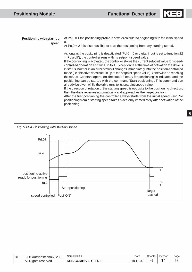
96 11 9KEB COMBIVERT F4-F
Name: Basis
18.12.02
6
Section PageDate© KEB Antriebstechnik, 2002All Rights reserved
Chapter
Functional DescriptionPositioning Module
Positioning with start-upspeed
At Pc.0 = 1 the positioning profile is always calculated beginning with the initial speed0.At Pc.0 = 2 it is also possible to start the positioning from any starting speed.
As long as the positoining is deactivated (Pd.0 = 0 or digital input is set to function 22= ‘Posi off’), the controller runs with its setpoint speed value.If the positioning is activated, the controller stores the current setpoint value for speed-controlled operation and runs up to it. Exception: If at the time of activation the drive isin status ‘noP’ or in an error status it changes immediately into the position-controlledmode (i.e. the drive does not run up to the setpoint speed value). Otherwise on reachingthe status ‘Constant operation’ the status ‘Ready for positioning’ is indicated and thepositioning can be started with the command ‘Start positioning’. This command canalready be given while the drive runs to its setpoint speed value.If the direction of rotation of the starting speed is opposite to the positioning direction,then the drive reverses automatically and approaches the target position.After the first positioning the controller always starts from the initial speed Zero. Sopositioning from a starting speed takes place only immediately after activation of thepositioning.
n
t
t
Pd.07
ru.20
Targetreached Posi ‘ON’
Start positioning
speed-controlled
Fig. 6.11.4 Positioning with start-up speed
ru.0
ready for positioning positioning active
6 11 KEB COMBIVERT F4-F10Name: Basis
18.12.02
Chapter Section Page Date © KEB Antriebstechnik, 2002All Rights reserved
Functional Description Positioning Module
6.11.6 Position Control-ler (Pd.2)
With Pd.2 the position controller can be individually optimized for every approachedposition. Provided that the total position adjustment supplies satisfactory results, anoptimization can be become necessary in following cases:
• target position is not reached• drive moves beyond the target position and returns then
This may be caused by a position controller which is adjusted too smooth.With Pd.2the controller can be adjusted in the range of 0....65535 (default value 20).
The software limit switches determine the range in which positions can be approached.If at the starting of the positioning the target position lies outside this range, then oneof the following errors is triggered:
• E.SLF (Error Software Limit Forward) Position outside the right softwarelimit switch
• E.SLr (Error Software Limit Reverse) Position outside the left softwarelimit switch
Depending on the selected position setting (revolutions or increments) different valueranges apply.Since the parameters are not locked against each other it is absolutely necessary toensure that with regard to the adjusted value the left software limit switch is locatedto the left of the right software limit switch. Following parameters define the softwarellimit switches:
• Left software limit switchPc.4 Sign (only at setting by way of increments)Pc.5 High (increments x 10.000 / complete revolutions)Pc.6 Low (increments x 1 / partial revolutions)
• Right software limit switchPc.7 Sign (only at setting by way of increments)Pc.8 High (increments x 10.000 / complete revolutions)Pc.9 Low (increments x 1 / partial revolutions)
6.11.7 Software LimitSwitch(Pc.4...Pc.9)
In the case of relative positioning (e.g. clock drive) the software limit switches can bedeactivated (factory setting). Following procedure must be carried out:
• Select position setting in revolutions Pc.1 = 3• Adjust left software limit switch to negative upper range value
Pc.5 = -32768Pc.6 = 0
• Adjust right software limit switch to positive upper range valuePc.8 = 32767Pc.9 = 65535
The behaviour at tripping of the faults ESLF and E.SLr is defined with Pn.20 accordingto following table:
Deactivation of software limitswitch
116 11 11KEB COMBIVERT F4-F
Name: Basis
18.12.02
6
Section PageDate© KEB Antriebstechnik, 2002All Rights reserved
Chapter
Functional DescriptionPositioning Module
Position Setting inRevolutions (Pd.9, Pd.10)
a) The drive shall run 13,7 revolutions clockwise (forward)
Pd.9 = 13 (or 0Dh)Pd.10 = 0,7 • 65536 = 45875 (or B333h)
b) The drive shall run 13,7 revolutions counter-clockwise (reverse)
-13,7 revolutions = -14 + 0,3 revolutions (since only positive partial revolutions)
Pd.9 = -14Pd.10 = (1 - 0,7) • 65536 = 19661 (or 4CCDh)
The adjustment/display is effected with two parameters (Pd.9, Pd.10). Pd.9 indicatescomplete revolutions in the range of -32768...32767 an. The rotation direction isdetermined by the sign. With Pd.10 partial revolutions in the range of 0...65535 areadjusted (65536 = 1 revolution of the position encoder).Please note that, when making the adjustment by way of the operator, the last digit inthe negative range starting at -9999 is not indicated by Pd.9.
Examples for position settingin revolutions
(relative positioning)
a) The drive shall run 13,75 revolutions clockwise
Pd.8 = 0 (+; forward)
13,75 • 65536 = 901.120 = 90 • 10.000 + 1120
Pd. 9 = 90Pd. 10= 1120
b) The drive shall run 13,75 revolutions counter-clockwise
Pd.8 = 1 (-; reverse)
13,75 * 65536 = 901.120 = 90 * 10.000 + 1120
Pd. 9 = 90Pd. 10= 1120
Regarding the position setting in increments the rotation direction is adjusted by wayof the sign in parameter (Pd.8). A complete revolution is represented internally with aresolution of 65536 increments. The ‘high’- parameter (Pd.9) contains the incrementsx 10.000, the ‘low’-parameter (Pd.10) contains the increments x 1.Please note that, when making the adjustment by way of the operator, the last digit asof 32767 is not indicated in parameter Pd.9.
Example for position settingin increments
(relative positioning)
Position Setting inIncrements (Pd.8...Pd.10)
The setpoint position can be preset in increments as well as in revolutions. This isdone in the parameters Pd.8...Pd.10 by adjusting increments or in the parametersPd.9...Pd.10 by adjusting revolutions.
6.11.8 Determining ofthe Set-position
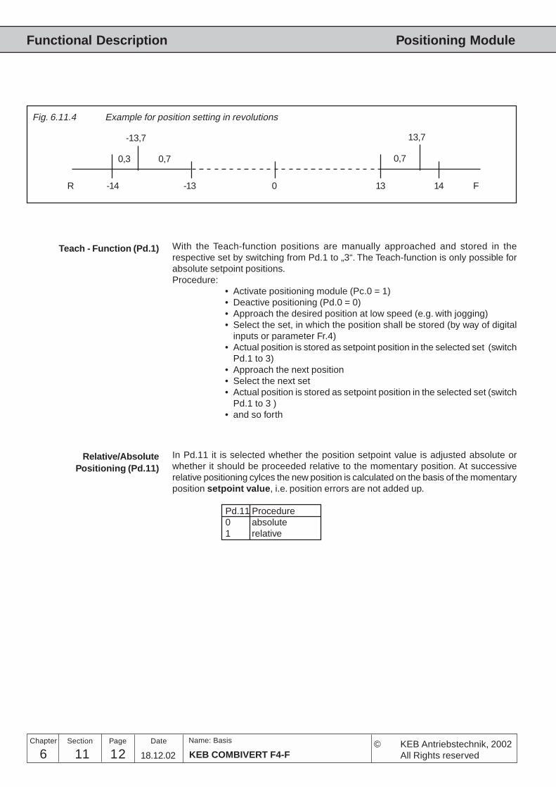
6 11 KEB COMBIVERT F4-F12Name: Basis
18.12.02
Chapter Section Page Date © KEB Antriebstechnik, 2002All Rights reserved
Functional Description Positioning Module
Fig. 6.11.4 Example for position setting in revolutions
R -14 -13 0 13 14 F
0,3 0,70,7
-13,7 13,7
Teach - Function (Pd.1) With the Teach-function positions are manually approached and stored in therespective set by switching from Pd.1 to „3“. The Teach-function is only possible forabsolute setpoint positions.Procedure:
• Activate positioning module (Pc.0 = 1)• Deactive positioning (Pd.0 = 0)• Approach the desired position at low speed (e.g. with jogging)• Select the set, in which the position shall be stored (by way of digital
inputs or parameter Fr.4)• Actual position is stored as setpoint position in the selected set (switch
Pd.1 to 3)• Approach the next position• Select the next set• Actual position is stored as setpoint position in the selected set (switch
Pd.1 to 3 )• and so forth
In Pd.11 it is selected whether the position setpoint value is adjusted absolute orwhether it should be proceeded relative to the momentary position. At successiverelative positioning cylces the new position is calculated on the basis of the momentaryposition setpoint value, i.e. position errors are not added up.
Pd.11 Procedure0 absolute1 relative
Relative/AbsolutePositioning (Pd.11)
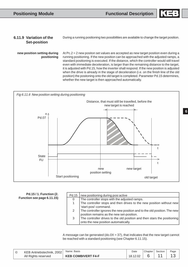
136 11 13KEB COMBIVERT F4-F
Name: Basis
18.12.02
6
Section PageDate© KEB Antriebstechnik, 2002All Rights reserved
Chapter
Functional DescriptionPositioning Module
Pd.15 new positioning during posi active0 The controller stops with the adjusted ramps.1 The controller stops and then drives to the new position without new
‘start-posi’-command.2 The controller ignores the new position and to the old position. The new
position remains as the new set-position.3 The controller drives to the old position and then stars the positioning
onto the new position automatically.
Pd.15 / 1. Function (2.Function see page 6.11.15)
n
t
t
Pd.07
Fig 6.11.6 New position setting during positioning
Start positioning
newposition setting
new target
old target
Distance, that must still be travelled, before thenew target is reached
At Pc.2 = 2 new positon set values are accepted as new target position even during arunning positioning. If the new position can be approached with the adjusted ramps, astandard positioning is executed. If the distance, which the controller would still traveleven with immediate deceleration, is larger than the remaining distance to the target,it is adjusted with Pd.15, how the inverter shall respond. If the new position is adjustedwhen the drive is already in the stage of deceleration (i.e. on the finish line of the oldposition) the positoning onto the old target is completed. Parameter Pd.15 determines,whether the new target is then approached automatically.
new position setting duringpositioning
6.11.9 Variation of theSet-position
During a running positioning two possibilities are available to change the target position.
StateFU
A message can be generated (do.0X = 37), that indicates that the new target cannotbe reached with a standard positioning (see Chapter 6.11.15).
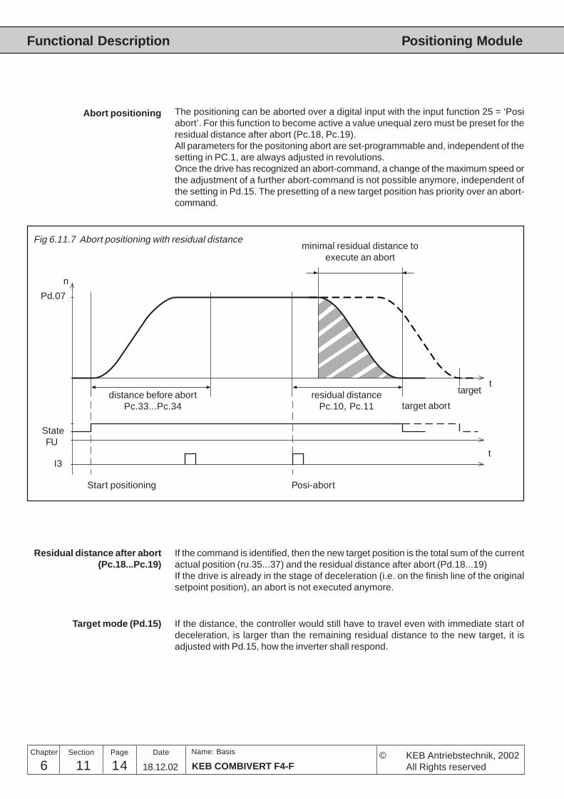
6 11 KEB COMBIVERT F4-F14Name: Basis
18.12.02
Chapter Section Page Date © KEB Antriebstechnik, 2002All Rights reserved
Functional Description Positioning Module
Residual distance after abort(Pc.18...Pc.19)
If the command is identified, then the new target position is the total sum of the currentactual position (ru.35...37) and the residual distance after abort (Pd.18...19)If the drive is already in the stage of deceleration (i.e. on the finish line of the originalsetpoint position), an abort is not executed anymore.
Target mode (Pd.15) If the distance, the controller would still have to travel even with immediate start ofdeceleration, is larger than the remaining residual distance to the new target, it isadjusted with Pd.15, how the inverter shall respond.
Abort positioning The positioning can be aborted over a digital input with the input function 25 = ‘Posiabort’. For this function to become active a value unequal zero must be preset for theresidual distance after abort (Pc.18, Pc.19).All parameters for the positoning abort are set-programmable and, independent of thesetting in PC.1, are always adjusted in revolutions.Once the drive has recognized an abort-command, a change of the maximum speed orthe adjustment of a further abort-command is not possible anymore, independent ofthe setting in Pd.15. The presetting of a new target position has priority over an abort-command.
Fig 6.11.7 Abort positioning with residual distance
n
t
t
Pd.07
StateFU
Start positioning
minimal residual distance toexecute an abort
distance before abortPc.33...Pc.34
residual distancePc.10, Pc.11 target abort
target
Posi-abort
I3
156 11 15KEB COMBIVERT F4-F
Name: Basis
18.12.02
6
Section PageDate© KEB Antriebstechnik, 2002All Rights reserved
Chapter
Functional DescriptionPositioning Module
Pd.15 Positionabort with residual distance
0 The controller stops and returns a message (do.0X = 37), that it couldnot reach the residual distance position.
1 The controller stops and returns a message (do.0X = 37), that it couldnot reach the residual distance position.
2 The controller ignores the position abort, drives to the position and returnsa message (do.0X = 37), that it could not reach the residual distanceposition.
3 The controller stops and returns a message (do.0X = 37), that it couldnot reach the residual distance position.
Pd.15 / 2. Function (1.Function see page 6.11.13)
Distance before abort(Pc.33...Pc.34)
During the positioning with abort (Pc.18 or Pc.19 uneven 0) a path can be pre-set inwhich the initiator signal for the abort shall not be evaluated.
Posi stop mode (Pc.36) Pc.36 Function0 State-active / residual distance after stop1 Edge-active / residual distance after stop2 State-active / stop before target position3 Edge-active / stop before target position
‘Stop before target position’ means that the abort maximally runs to the originallyadjusted target position (target position before abort). With the setting ‘Residual distanceafter stop’ the residual distance (Pc.18, Pc.19) is in any case still travelled afterrecognizing the stop signal. Edge-active means that the ‘Posi abort command’ isexecuted only if the signal edge comes during the current positioning. With ‘Statusactive’ the signal edge of the abort command can come before the ‘Start positioningcommand’. If the abort signal is still active at the start of the positioning, then the abortis executed immediately.
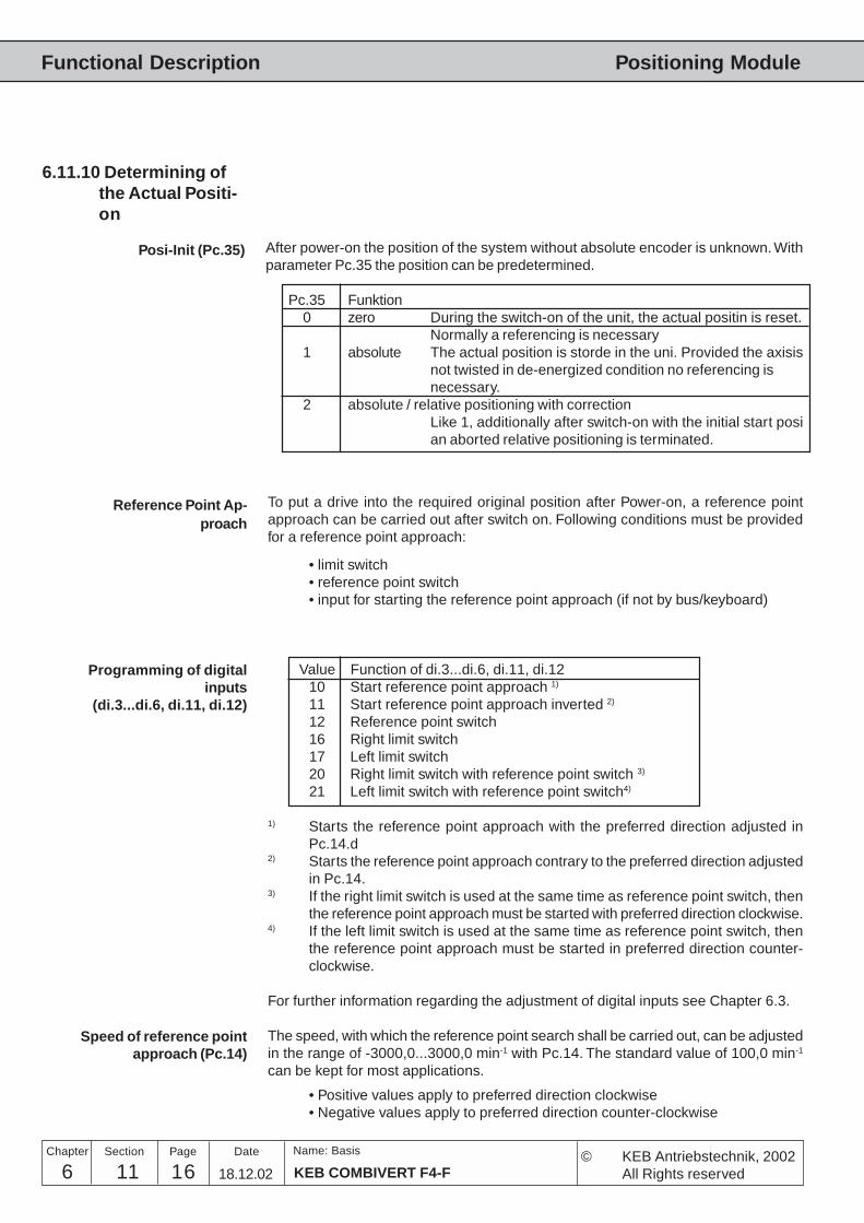
6 11 KEB COMBIVERT F4-F16Name: Basis
18.12.02
Chapter Section Page Date © KEB Antriebstechnik, 2002All Rights reserved
Functional Description Positioning Module
Reference Point Ap-proach
To put a drive into the required original position after Power-on, a reference pointapproach can be carried out after switch on. Following conditions must be providedfor a reference point approach:
• limit switch• reference point switch• input for starting the reference point approach (if not by bus/keyboard)
Value Function of di.3...di.6, di.11, di.1210 Start reference point approach 1)
11 Start reference point approach inverted 2)
12 Reference point switch16 Right limit switch17 Left limit switch20 Right limit switch with reference point switch 3)
21 Left limit switch with reference point switch4)
1) Starts the reference point approach with the preferred direction adjusted inPc.14.d
2) Starts the reference point approach contrary to the preferred direction adjustedin Pc.14.
3) If the right limit switch is used at the same time as reference point switch, thenthe reference point approach must be started with preferred direction clockwise.
4) If the left limit switch is used at the same time as reference point switch, thenthe reference point approach must be started in preferred direction counter-clockwise.
For further information regarding the adjustment of digital inputs see Chapter 6.3.
The speed, with which the reference point search shall be carried out, can be adjustedin the range of -3000,0...3000,0 min-1 with Pc.14. The standard value of 100,0 min-1
can be kept for most applications.
• Positive values apply to preferred direction clockwise• Negative values apply to preferred direction counter-clockwise
Programming of digitalinputs
(di.3...di.6, di.11, di.12)
Speed of reference pointapproach (Pc.14)
After power-on the position of the system without absolute encoder is unknown. Withparameter Pc.35 the position can be predetermined.
Pc.35 Funktion0 zero During the switch-on of the unit, the actual positin is reset.
Normally a referencing is necessary1 absolute The actual position is storde in the uni. Provided the axisis
not twisted in de-energized condition no referencing isnecessary.
2 absolute / relative positioning with correctionLike 1, additionally after switch-on with the initial start posian aborted relative positioning is terminated.
Posi-Init (Pc.35)
6.11.10 Determining ofthe Actual Positi-on
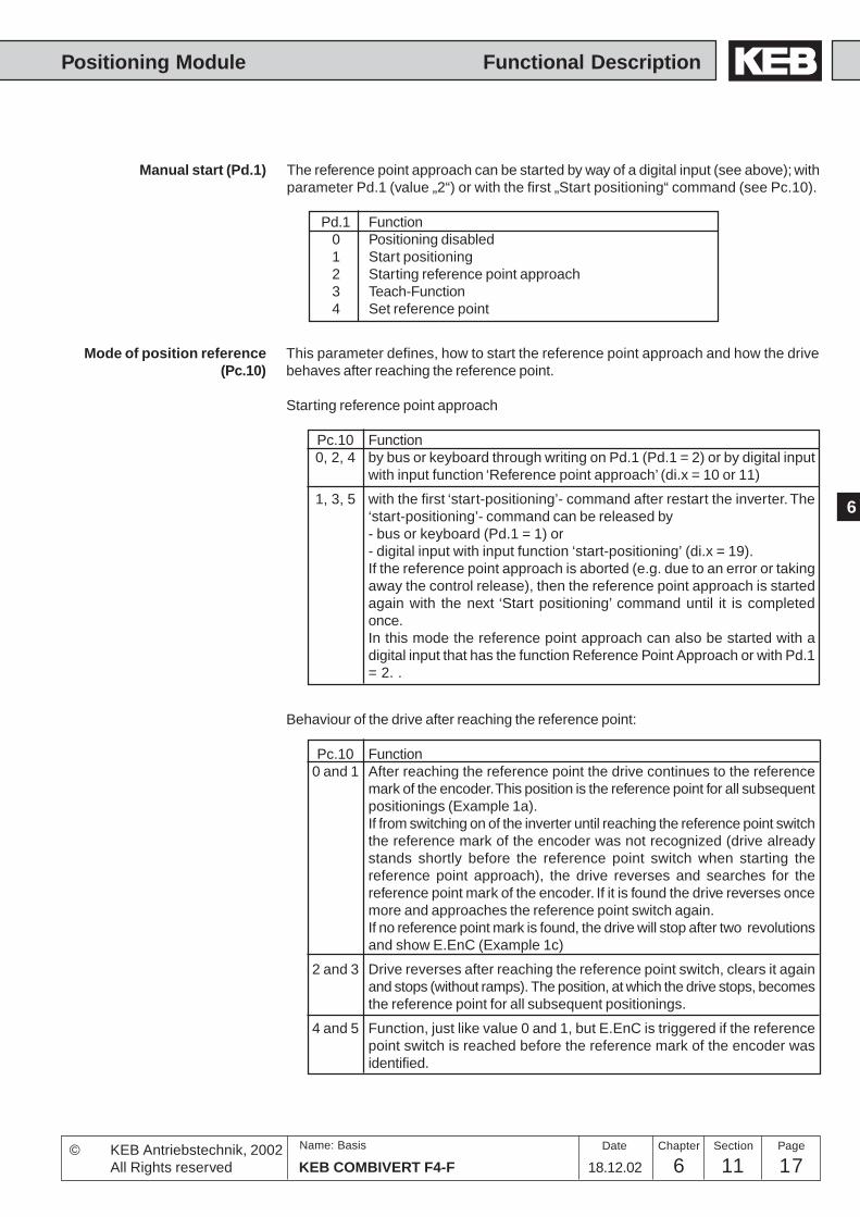
176 11 17KEB COMBIVERT F4-F
Name: Basis
18.12.02
6
Section PageDate© KEB Antriebstechnik, 2002All Rights reserved
Chapter
Functional DescriptionPositioning Module
Manual start (Pd.1) The reference point approach can be started by way of a digital input (see above); withparameter Pd.1 (value „2“) or with the first „Start positioning“ command (see Pc.10).
Pd.1 Function0 Positioning disabled1 Start positioning2 Starting reference point approach3 Teach-Function4 Set reference point
Mode of position reference(Pc.10)
Behaviour of the drive after reaching the reference point:
Pc.10 Function0 and 1 After reaching the reference point the drive continues to the reference
mark of the encoder. This position is the reference point for all subsequentpositionings (Example 1a).If from switching on of the inverter until reaching the reference point switchthe reference mark of the encoder was not recognized (drive alreadystands shortly before the reference point switch when starting thereference point approach), the drive reverses and searches for thereference point mark of the encoder. If it is found the drive reverses oncemore and approaches the reference point switch again.If no reference point mark is found, the drive will stop after two revolutionsand show E.EnC (Example 1c)
2 and 3 Drive reverses after reaching the reference point switch, clears it againand stops (without ramps). The position, at which the drive stops, becomesthe reference point for all subsequent positionings.
4 and 5 Function, just like value 0 and 1, but E.EnC is triggered if the referencepoint switch is reached before the reference mark of the encoder wasidentified.
This parameter defines, how to start the reference point approach and how the drivebehaves after reaching the reference point.
Starting reference point approach
Pc.10 Function0, 2, 4 by bus or keyboard through writing on Pd.1 (Pd.1 = 2) or by digital input
with input function ‘Reference point approach’ (di.x = 10 or 11)
1, 3, 5 with the first ‘start-positioning’- command after restart the inverter. The‘start-positioning’- command can be released by- bus or keyboard (Pd.1 = 1) or- digital input with input function ‘start-positioning’ (di.x = 19).If the reference point approach is aborted (e.g. due to an error or takingaway the control release), then the reference point approach is startedagain with the next ‘Start positioning’ command until it is completedonce.In this mode the reference point approach can also be started with adigital input that has the function Reference Point Approach or with Pd.1= 2. .
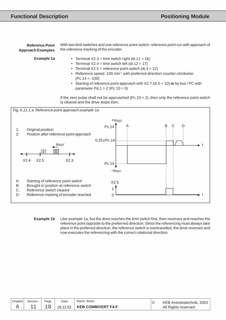
6 11 KEB COMBIVERT F4-F18Name: Basis
18.12.02
Chapter Section Page Date © KEB Antriebstechnik, 2002All Rights reserved
Functional Description Positioning Module
With two limit switches and one reference point switch; reference point run with approach ofthe reference marking of the encoder.
• Terminal X2.3 = limit switch right (di.11 = 16)• Terminal X2.4 = limit switch left (di.12 = 17)• Terminal X2.5 = reference point switch (di.3 = 12)• Reference speed -100 min-1 with preferred direction counter-clockwise
(Pc.14 = -100)• Starting of reference point approach with X2.7 (di.5 = 10) or by bus / PC with
parameter Pd.1 = 2 (Pc.10 = 0)
If the zero pulse shall not be approached (Pc.10 = 2), then only the reference point switchis cleared and the drive stops then.
Example 1a
X2.4 X2.3
vREF
12
X2.5
+vREF
-vREF
t
Pc.14
Pc.14
0,25xPc.14
A B C D
t0
1
X2.5A: Starting of reference point switchB: Brought in position at reference switchC: Reference switch clearedD: Reference marking of encoder reached
1: Original position2: Position after reference point approach
Fig. 6.11.1.a Reference point approach example 1a
Reference PointApproach Examples
Example 1b Like example 1a, but the drive reaches the limit switch first, then reverses and reaches thereference point opposite to the preferrred direction. Since the referencing must always takeplace in the preferred direction, the reference switch is overtravelled, the drive reverses andnow executes the referencing with the correct rotational direction.
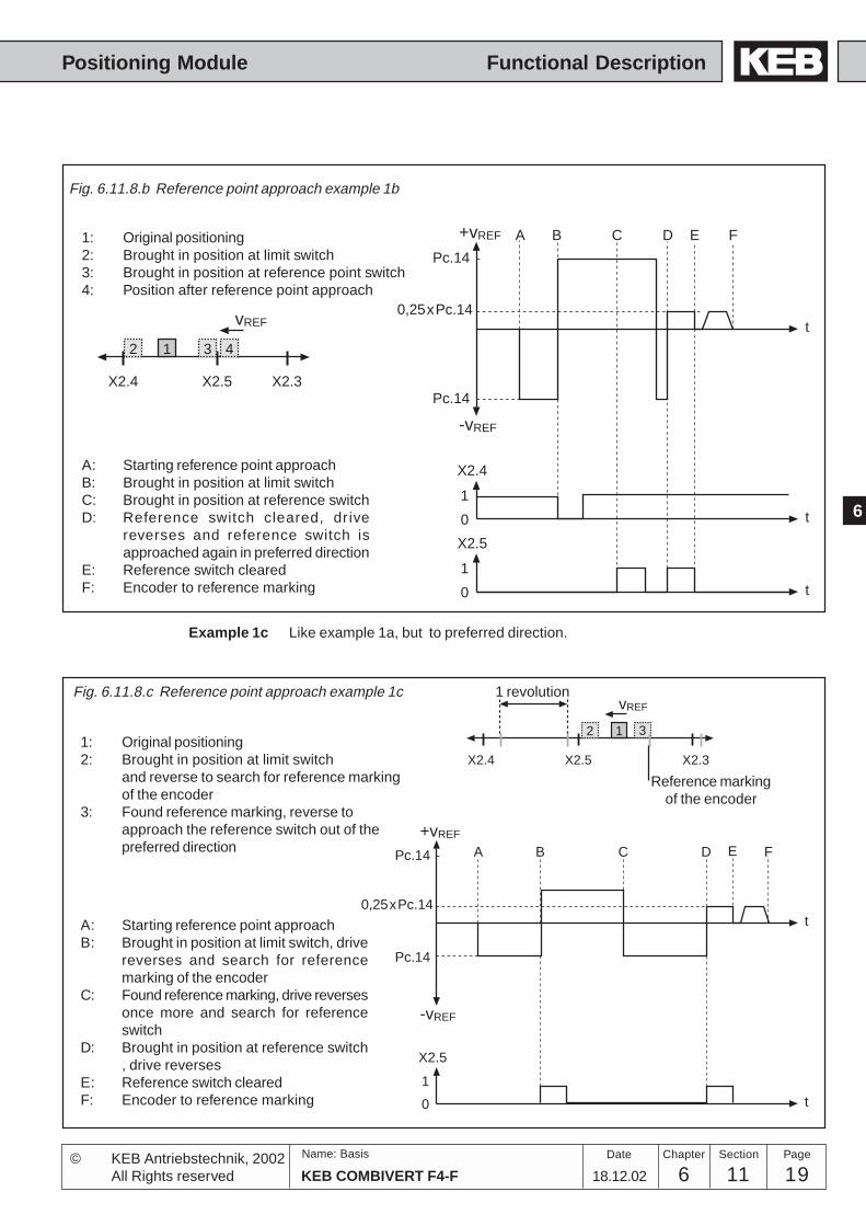
196 11 19KEB COMBIVERT F4-F
Name: Basis
18.12.02
6
Section PageDate© KEB Antriebstechnik, 2002All Rights reserved
Chapter
Functional DescriptionPositioning Module
X2.4 X2.3
vREF
12
X2.5
3
+vREF
-vREF
t
Pc.14
Pc.14
0,25xPc.14
A B C D
t0
1
X2.5
E F
1 revolution
Reference markingof the encoder
Fig. 6.11.8.c Reference point approach example 1c
A: Starting reference point approachB: Brought in position at limit switch, drive
reverses and search for referencemarking of the encoder
C: Found reference marking, drive reversesonce more and search for referenceswitch
D: Brought in position at reference switch, drive reverses
E: Reference switch clearedF: Encoder to reference marking
1: Original positioning2: Brought in position at limit switch
and reverse to search for reference markingof the encoder
3: Found reference marking, reverse toapproach the reference switch out of thepreferred direction
Like example 1a, but to preferred direction.Example 1c
X2.4 X2.3
vREF
12
X2.5
3 4
A: Starting reference point approachB: Brought in position at limit switchC: Brought in position at reference switchD: Reference switch cleared, dr ive
reverses and reference switch isapproached again in preferred direction
E: Reference switch clearedF: Encoder to reference marking
1: Original positioning2: Brought in position at limit switch3: Brought in position at reference point switch4: Position after reference point approach
Fig. 6.11.8.b Reference point approach example 1b
+vREF
-vREF
t
Pc.14
Pc.14
0,25xPc.14
A D E F
t0
1
X2.4
t0
1
X2.5
B C
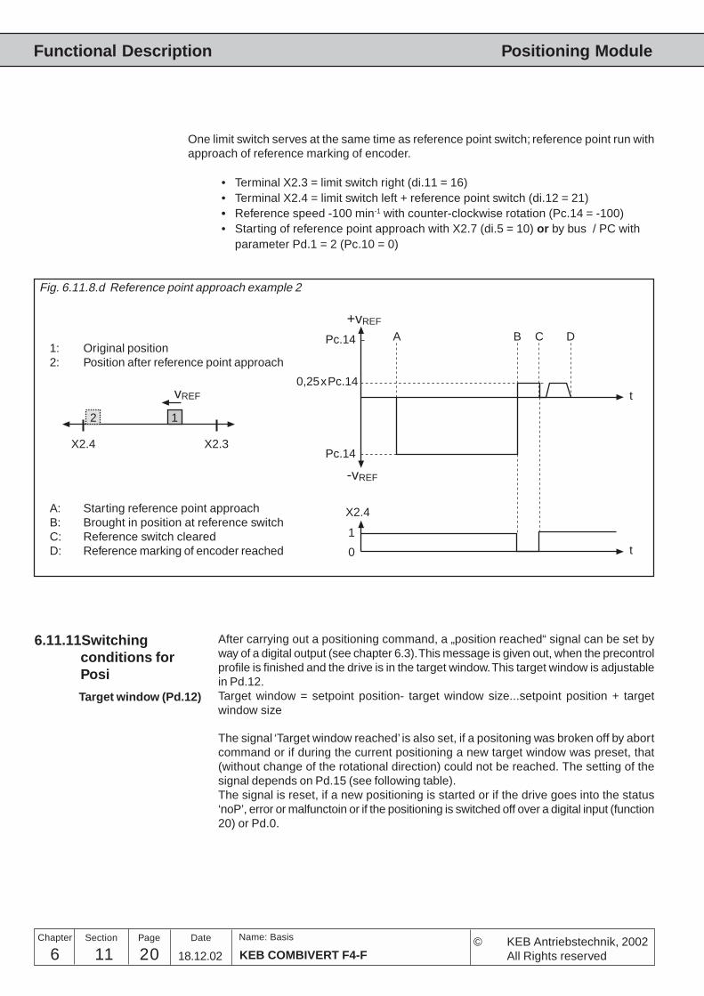
6 11 KEB COMBIVERT F4-F20Name: Basis
18.12.02
Chapter Section Page Date © KEB Antriebstechnik, 2002All Rights reserved
Functional Description Positioning Module
One limit switch serves at the same time as reference point switch; reference point run withapproach of reference marking of encoder.
• Terminal X2.3 = limit switch right (di.11 = 16)• Terminal X2.4 = limit switch left + reference point switch (di.12 = 21)• Reference speed -100 min-1 with counter-clockwise rotation (Pc.14 = -100)• Starting of reference point approach with X2.7 (di.5 = 10) or by bus / PC with
parameter Pd.1 = 2 (Pc.10 = 0)
X2.4 X2.3
vREF
12
+vREF
-vREF
t
Pc.14
Pc.14
0,25xPc.14
A B C D
t0
1
X2.4A: Starting reference point approachB: Brought in position at reference switchC: Reference switch clearedD: Reference marking of encoder reached
1: Original position2: Position after reference point approach
Fig. 6.11.8.d Reference point approach example 2
6.11.11Switchingconditions forPosi
Target window (Pd.12)
The signal ‘Target window reached’ is also set, if a positoning was broken off by abortcommand or if during the current positioning a new target window was preset, that(without change of the rotational direction) could not be reached. The setting of thesignal depends on Pd.15 (see following table).The signal is reset, if a new positioning is started or if the drive goes into the status‘noP’, error or malfunctoin or if the positioning is switched off over a digital input (function20) or Pd.0.
After carrying out a positioning command, a „position reached“ signal can be set byway of a digital output (see chapter 6.3). This message is given out, when the precontrolprofile is finished and the drive is in the target window. This target window is adjustablein Pd.12.Target window = setpoint position- target window size...setpoint position + targetwindow size
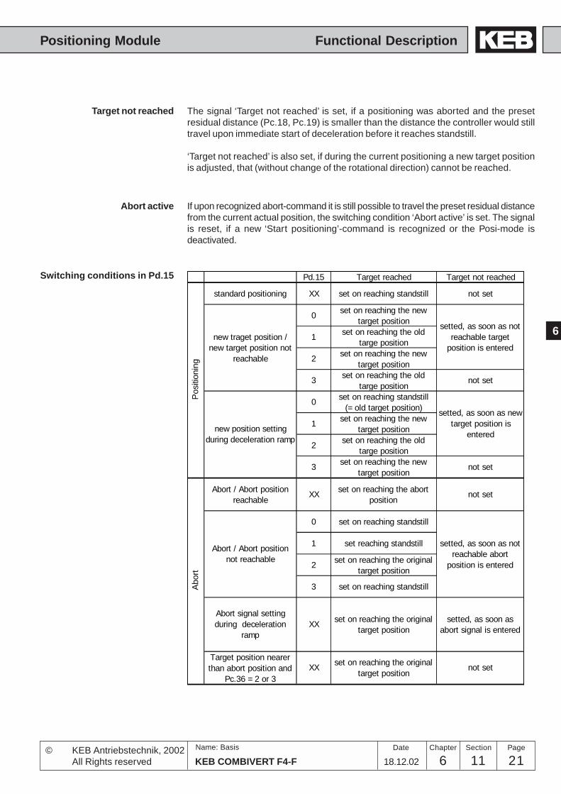
216 11 21KEB COMBIVERT F4-F
Name: Basis
18.12.02
6
Section PageDate© KEB Antriebstechnik, 2002All Rights reserved
Chapter
Functional DescriptionPositioning Module
Pd.15 Target reached Target not reached
not set
not set
setted, as soon as new target position is
entered
3
Pos
ition
ing
set on reaching the new target position
set on reaching standstill (= old target position)
set on reaching the new target position
set on reaching the old targe position
standard positioning
new traget position / new target position not
reachable
new position setting during deceleration ramp
set on reaching the new target position
set on reaching the old targe position
set on reaching the new target position
set on reaching the old targe position
XX
0
1
set on reaching the abort position
not set
2
set on reaching standstill not set
2
3
0
1
setted, as soon as not reachable target
position is entered
Abo
rt
0
1
2
Abort / Abort position reachable
Abort / Abort position not reachable
Abort signal setting during deceleration
ramp
Target position nearer than abort position and
Pc.36 = 2 or 3
XX
3
set reaching standstill
set on reaching the original target position
set on reaching standstill
setted, as soon as not reachable abort
position is entered
set on reaching standstill
XX
XXsetted, as soon as
abort signal is entered
not set
set on reaching the original target position
set on reaching the original target position
Abort active If upon recognized abort-command it is still possible to travel the preset residual distancefrom the current actual position, the switching condition ‘Abort active’ is set. The signalis reset, if a new ‘Start positioning’-command is recognized or the Posi-mode isdeactivated.
Switching conditions in Pd.15
Target not reached The signal ‘Target not reached’ is set, if a positioning was aborted and the presetresidual distance (Pc.18, Pc.19) is smaller than the distance the controller would stilltravel upon immediate start of deceleration before it reaches standstill.
‘Target not reached’ is also set, if during the current positioning a new target positionis adjusted, that (without change of the rotational direction) cannot be reached.
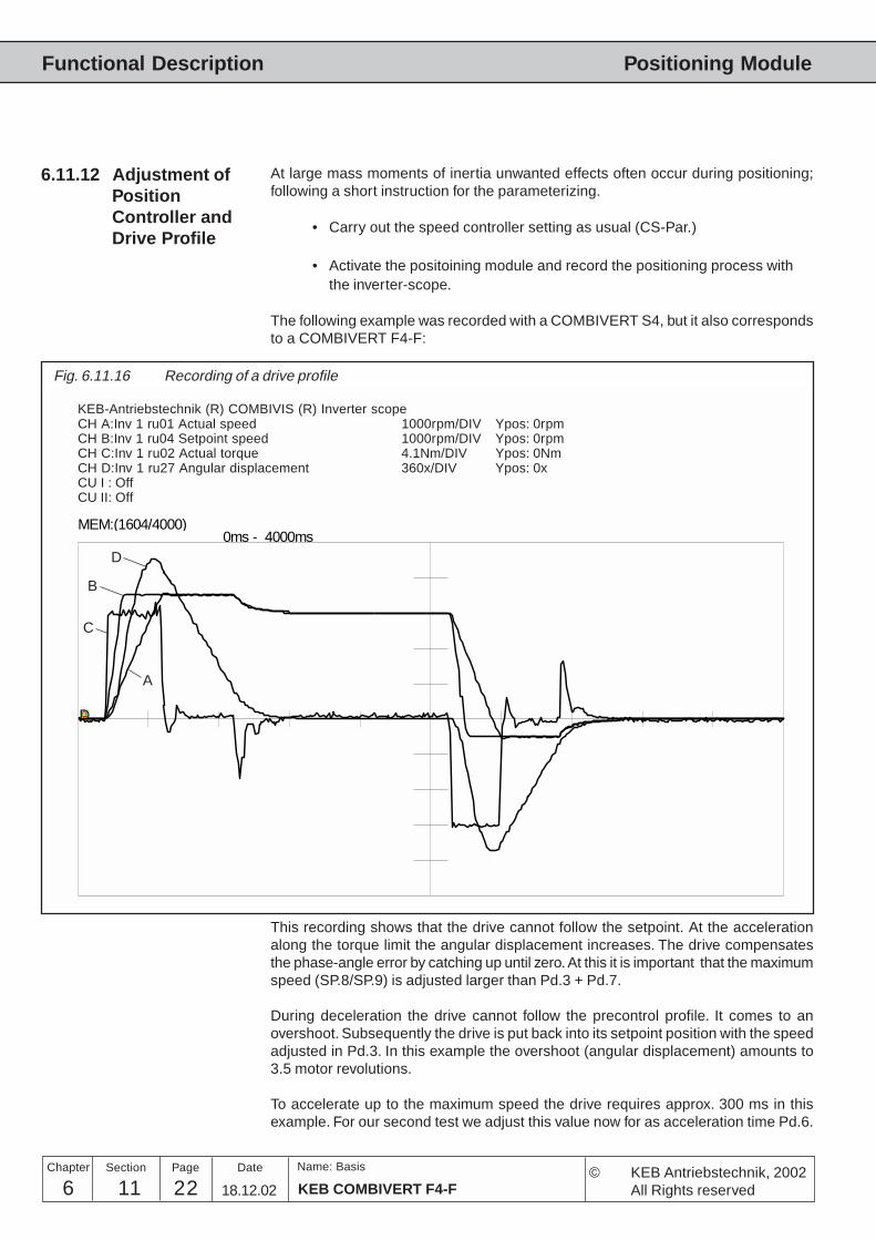
6 11 KEB COMBIVERT F4-F22Name: Basis
18.12.02
Chapter Section Page Date © KEB Antriebstechnik, 2002All Rights reserved
Functional Description Positioning Module
KEB-Antriebstechnik (R) COMBIVIS (R) Inverter scopeCH A:Inv 1 ru01 Istdrehzahl 1000rpm/DIV Ypos: 0rpmCH B:Inv 1 ru04 Solldrehzahl 1000rpm/DIV Ypos: 0rpmCH C:Inv 1 ru02 Istmoment 4.1Nm/DIV Ypos: 0NmCH D:Inv 1 ru27 Winkelabweichung 360x/DIV Ypos: 0xCU I : OffCU II: Off
MEM:(1604/4000) 0ms - 4000ms
ABCD
6.11.12 Adjustment ofPositionController andDrive Profile
At large mass moments of inertia unwanted effects often occur during positioning;following a short instruction for the parameterizing.
• Carry out the speed controller setting as usual (CS-Par.)
• Activate the positoining module and record the positioning process withthe inverter-scope.
The following example was recorded with a COMBIVERT S4, but it also correspondsto a COMBIVERT F4-F:
Fig. 6.11.16 Recording of a drive profile
This recording shows that the drive cannot follow the setpoint. At the accelerationalong the torque limit the angular displacement increases. The drive compensatesthe phase-angle error by catching up until zero. At this it is important that the maximumspeed (SP.8/SP.9) is adjusted larger than Pd.3 + Pd.7.
During deceleration the drive cannot follow the precontrol profile. It comes to anovershoot. Subsequently the drive is put back into its setpoint position with the speedadjusted in Pd.3. In this example the overshoot (angular displacement) amounts to3.5 motor revolutions.
To accelerate up to the maximum speed the drive requires approx. 300 ms in thisexample. For our second test we adjust this value now for as acceleration time Pd.6.
D
B
C
A
KEB-Antriebstechnik (R) COMBIVIS (R) Inverter scopeCH A:Inv 1 ru01 Actual speed 1000rpm/DIV Ypos: 0rpmCH B:Inv 1 ru04 Setpoint speed 1000rpm/DIV Ypos: 0rpmCH C:Inv 1 ru02 Actual torque 4.1Nm/DIV Ypos: 0NmCH D:Inv 1 ru27 Angular displacement 360x/DIV Ypos: 0xCU I : OffCU II: Off
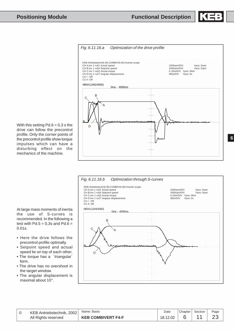
236 11 23KEB COMBIVERT F4-F
Name: Basis
18.12.02
6
Section PageDate© KEB Antriebstechnik, 2002All Rights reserved
Chapter
Functional DescriptionPositioning Module
KEB-Antriebstechnik (R) COMBIVIS (R) Inverter scopeCH A:Inv 1 ru01 Istdrehzahl 1000rpm/DIV Ypos: 0rpmCH B:Inv 1 ru04 Solldrehzahl 1000rpm/DIV Ypos: 0rpmCH C:Inv 1 ru02 Istmoment 4.1Nm/DIV Ypos: 0NmCH D:Inv 1 ru27 Winkelabweichung 10x/DIV Ypos: 0xCU I : OffCU II: Off
MEM:(1492/4000) 0ms - 4000ms
ABCD
Fig. 6.11.16.a Optimization of the drive profile
With this setting Pd.6 = 0,3 s thedrive can follow the precontrolprofile. Only the corner points ofthe precontrol profile show torqueimpulses which can have adisturbing effect on themechanics of the machine.
KEB-Antriebstechnik (R) COMBIVIS (R) Inverter scope V3.7CH A:Inv 1 ru01 Istdrehzahl 1000rpm/DIV Ypos: 0rpmCH B:Inv 1 ru04 Solldrehzahl 1000rpm/DIV Ypos: 0rpmCH C:Inv 1 ru02 Istmoment 4.1Nm/DIV Ypos: 0NmCH D:Inv 1 ru27 Winkelabweichung 10x/DIV Ypos: 0xCU I : OffCU II: Off
MEM:(1344/4000) 0ms - 4000ms
ABCD
Fig. 6.11.16.b Optimization through S-curves
At large mass moments of inertiathe use of S-curves isrecommended. In the following atest with Pd.5 = 0,3s and Pd.6 =0.01s.
• Here the drive follows theprecontrol profile optimally.
• Setpoint speed and actualspeed lie on top of each other.
• The torque has a ´triangular´form.
• The drive has no overshoot inthe target window.
• The angular displacement ismaximal about 10°.
D
BC
A
D
B
C A
KEB-Antriebstechnik (R) COMBIVIS (R) Inverter scopeCH A:Inv 1 ru01 Actual speed 1000rpm/DIV Ypos: 0rpmCH B:Inv 1 ru04 Setpoint speed 1000rpm/DIV Ypos: 0rpmCH C:Inv 1 ru02 Actual torque 4.1Nm/DIV Ypos: 0NmCH D:Inv 1 ru27 Angular displacement 360x/DIV Ypos: 0xCU I : OffCU II: Off
KEB-Antriebstechnik (R) COMBIVIS (R) Inverter scopeCH A:Inv 1 ru01 Actual speed 1000rpm/DIV Ypos: 0rpmCH B:Inv 1 ru04 Setpoint speed 1000rpm/DIV Ypos: 0rpmCH C:Inv 1 ru02 Actual torque 4.1Nm/DIV Ypos: 0NmCH D:Inv 1 ru27 Angular displacement 360x/DIV Ypos: 0xCU I : OffCU II: Off
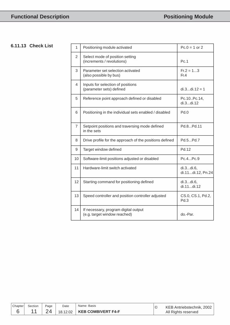
6 11 KEB COMBIVERT F4-F24Name: Basis
18.12.02
Chapter Section Page Date © KEB Antriebstechnik, 2002All Rights reserved
Functional Description Positioning Module
6.11.13 Check List 1 Positioning module activated Pc.0 = 1 or 2
2 Select mode of position setting(increments / revolutions) Pc.1
3 Parameter set selection activated Fr.2 = 1...3(also possible by bus) Fr.4
4 Inputs for selection of positions(parameter sets) defined di.3...di.12 = 1
5 Reference point approach defined or disabled Pc.10..Pc.14,di.3...di.12
6 Positioning in the individual sets enabled / disabled Pd.0
7 Setpoint positions and traversing mode defined Pd.8...Pd.11in the sets
8 Drive profile for the approach of the positions defined Pd.5...Pd.7
9 Target window defined Pd.12
10 Software-limit positions adjusted or disabled Pc.4...Pc.9
11 Hardware-limit switch activated di.3...di.6,di.11...di.12, Pn.24
12 Starting command for positioning defined di.3...di.6,di.11...di.12
13 Speed controller and position controller adjusted CS.0, CS.1, Pd.2,Pd.3
14 If necessary, program digital output(e.g. target window reached) do.-Par.
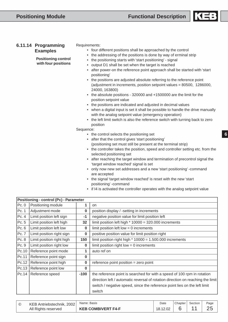
256 11 25KEB COMBIVERT F4-F
Name: Basis
18.12.02
6
Section PageDate© KEB Antriebstechnik, 2002All Rights reserved
Chapter
Functional DescriptionPositioning Module
6.11.14 ProgrammingExamples
Positioning controlwith four positions
Requirements:• four different positions shall be approached by the control• the addressing of the positions is done by way of erminal strip• the positioning starts with ‘start positioning’ - signal• output D1 shall be set when the target is reached• after power-on the reference point approach shall be started with ‘start
positioning’• the positions are adjusted absolute referring to the reference point
(adjustment in increments, position setpoint values = 80500, 1286000,24000, 163800)
• the absolute positions - 320000 and +1500000 are the limit for theposition setpoint value
• the positions are indicated and adjusted in decimal values• when a digital input is set it shall be possible to handle the drive manually
with the analog setpoint value (emergency operation)• the left limit switch is also the reference switch with turning back to zero
positionSequence:
• the control selects the positioning set• after that the control gives ‘start positioning’
(positioning set must still be present at the terminal strip)• the controller takes the position, speed and controller setting etc. from the
selected positioning set• after reaching the target window and termination of precontrol signal the
‘target window reached‘ signal is set• only now new set addresses and a new ‘start positioning’ -command
are accepted• the signal ‘target window reached’ is reset with the new ‘start
positioning’ -command• if I4 is activated the controller operates with the analog setpoint value
Positioning - control (Pc) - ParameterPc. 0 Positioning module 1 on
Pc. 1 Adjustment mode 0 position display / -setting in increments
Pc. 4 Limit position left sign -1 negative position value for limit position left
Pc. 5 Limit position left high 32 limit position left high * 10000 = 320.000 increments
Pc. 6 Limit position left low 0 limit position left low = 0 increments
Pc. 7 Limit position right sign 0 positive position value for limit position right
Pc. 8 Limit position right high 150 limit position right high * 10000 = 1.500.000 increments
Pc. 9 Limit position right low 0 limit position right low = 0 increments
Pc.10 Reference point mode 1 auto ref on
Pc.11 Reference point sign 0
Pc.12 Reference point high 0 reference point position = zero point
Pc.13 Reference point low 0
Pc.14 Reference speed -100 the reference point is searched for with a speed of 100 rpm in rotation
direction left / automatic reversal of rotation direction on reaching the limit
switch / negative speed, since the reference point lies on the left limit
switch
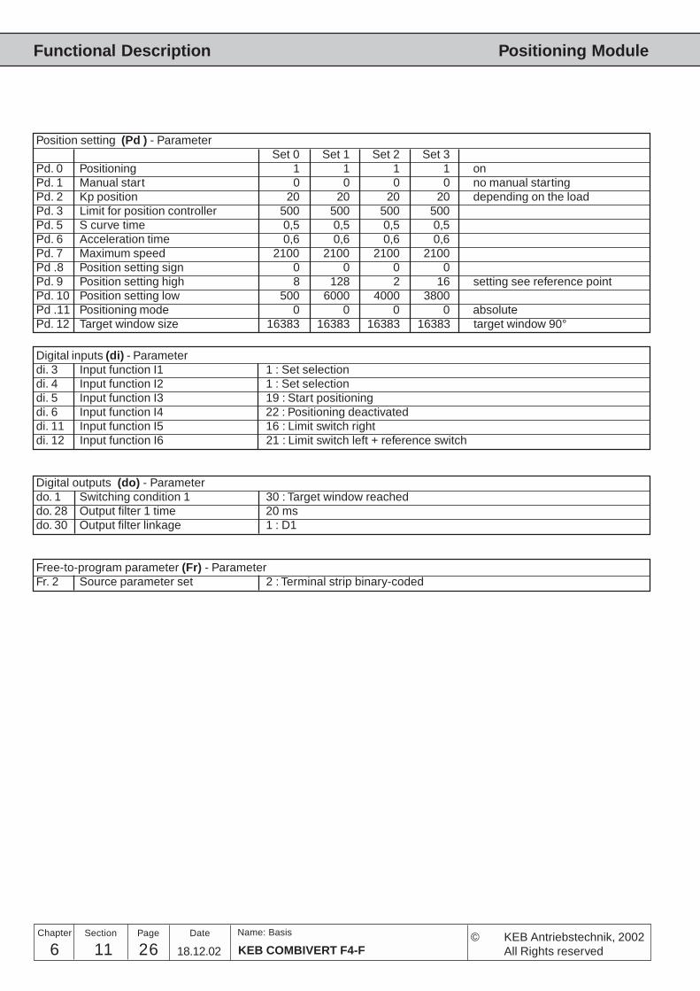
6 11 KEB COMBIVERT F4-F26Name: Basis
18.12.02
Chapter Section Page Date © KEB Antriebstechnik, 2002All Rights reserved
Functional Description Positioning Module
Position setting (Pd ) - ParameterSet 0 Set 1 Set 2 Set 3
Pd. 0 Positioning 1 1 1 1 onPd. 1 Manual start 0 0 0 0 no manual startingPd. 2 Kp position 20 20 20 20 depending on the loadPd. 3 Limit for position controller 500 500 500 500Pd. 5 S curve time 0,5 0,5 0,5 0,5Pd. 6 Acceleration time 0,6 0,6 0,6 0,6Pd. 7 Maximum speed 2100 2100 2100 2100Pd .8 Position setting sign 0 0 0 0Pd. 9 Position setting high 8 128 2 16 setting see reference pointPd. 10 Position setting low 500 6000 4000 3800Pd .11 Positioning mode 0 0 0 0 absolutePd. 12 Target window size 16383 16383 16383 16383 target window 90°
Digital inputs (di) - Parameterdi. 3 Input function I1 1 : Set selectiondi. 4 Input function I2 1 : Set selectiondi. 5 Input function I3 19 : Start positioningdi. 6 Input function I4 22 : Positioning deactivateddi. 11 Input function I5 16 : Limit switch rightdi. 12 Input function I6 21 : Limit switch left + reference switch
Digital outputs (do) - Parameterdo. 1 Switching condition 1 30 : Target window reacheddo. 28 Output filter 1 time 20 msdo. 30 Output filter linkage 1 : D1
Free-to-program parameter (Fr) - ParameterFr. 2 Source parameter set 2 : Terminal strip binary-coded
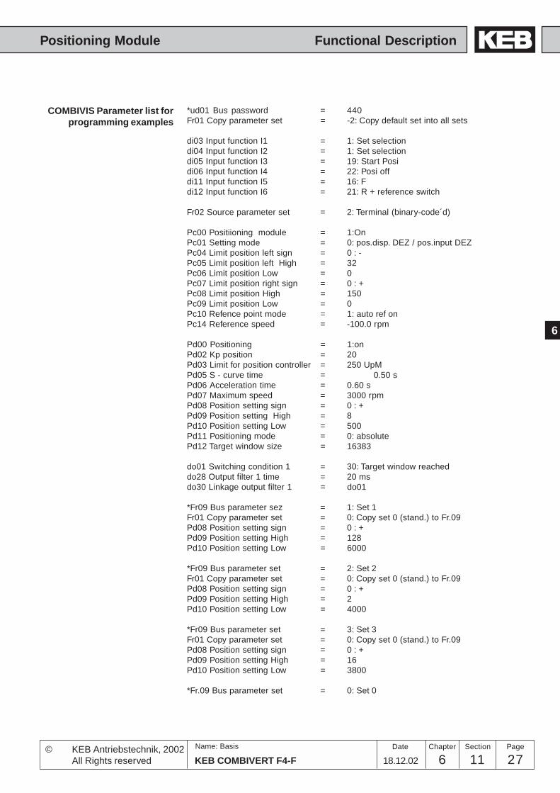
276 11 27KEB COMBIVERT F4-F
Name: Basis
18.12.02
6
Section PageDate© KEB Antriebstechnik, 2002All Rights reserved
Chapter
Functional DescriptionPositioning Module
*ud01 Bus password = 440Fr01 Copy parameter set = -2: Copy default set into all sets
di03 Input function I1 = 1: Set selectiondi04 Input function I2 = 1: Set selectiondi05 Input function I3 = 19: Start Posidi06 Input function I4 = 22: Posi offdi11 Input function I5 = 16: Fdi12 Input function I6 = 21: R + reference switch
Fr02 Source parameter set = 2: Terminal (binary-code´d)
Pc00 Positiioning module = 1:OnPc01 Setting mode = 0: pos.disp. DEZ / pos.input DEZPc04 Limit position left sign = 0 : -Pc05 Limit position left High = 32Pc06 Limit position Low = 0Pc07 Limit position right sign = 0 : +Pc08 Limit position High = 150Pc09 Limit position Low = 0Pc10 Refence point mode = 1: auto ref onPc14 Reference speed = -100.0 rpm
Pd00 Positioning = 1:onPd02 Kp position = 20Pd03 Limit for position controller = 250 UpMPd05 S - curve time = 0.50 sPd06 Acceleration time = 0.60 sPd07 Maximum speed = 3000 rpmPd08 Position setting sign = 0 : +Pd09 Position setting High = 8Pd10 Position setting Low = 500Pd11 Positioning mode = 0: absolutePd12 Target window size = 16383
do01 Switching condition 1 = 30: Target window reacheddo28 Output filter 1 time = 20 msdo30 Linkage output filter 1 = do01
*Fr09 Bus parameter sez = 1: Set 1Fr01 Copy parameter set = 0: Copy set 0 (stand.) to Fr.09Pd08 Position setting sign = 0 : +Pd09 Position setting High = 128Pd10 Position setting Low = 6000
*Fr09 Bus parameter set = 2: Set 2Fr01 Copy parameter set = 0: Copy set 0 (stand.) to Fr.09Pd08 Position setting sign = 0 : +Pd09 Position setting High = 2Pd10 Position setting Low = 4000
*Fr09 Bus parameter set = 3: Set 3Fr01 Copy parameter set = 0: Copy set 0 (stand.) to Fr.09Pd08 Position setting sign = 0 : +Pd09 Position setting High = 16Pd10 Position setting Low = 3800
*Fr.09 Bus parameter set = 0: Set 0
COMBIVIS Parameter list forprogramming examples
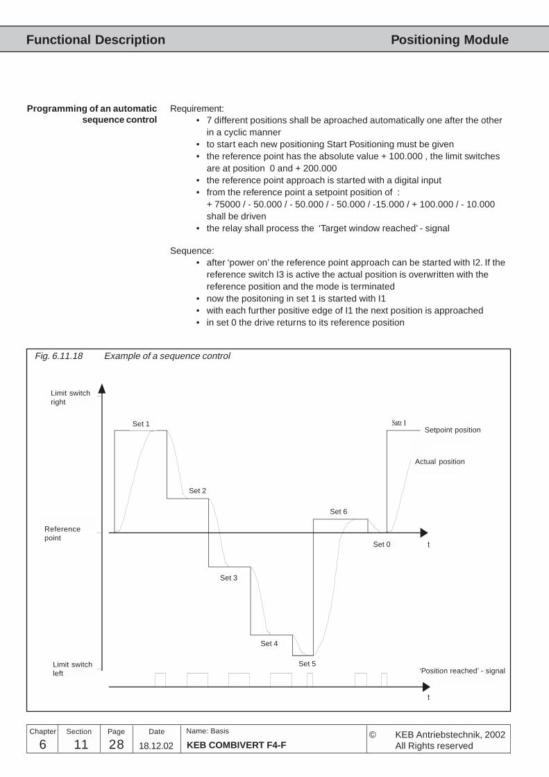
6 11 KEB COMBIVERT F4-F28Name: Basis
18.12.02
Chapter Section Page Date © KEB Antriebstechnik, 2002All Rights reserved
Functional Description Positioning Module
Requirement:• 7 different positions shall be aproached automatically one after the other
in a cyclic manner• to start each new positioning Start Positioning must be given• the reference point has the absolute value + 100.000 , the limit switches
are at position 0 and + 200.000• the reference point approach is started with a digital input• from the reference point a setpoint position of :
+ 75000 / - 50.000 / - 50.000 / - 50.000 / -15.000 / + 100.000 / - 10.000shall be driven
• the relay shall process the ‘Target window reached’ - signal
Sequence:• after ‘power on’ the reference point approach can be started with I2. If the
reference switch I3 is active the actual position is overwritten with thereference position and the mode is terminated
• now the positoning in set 1 is started with I1• with each further positive edge of I1 the next position is approached• in set 0 the drive returns to its reference position
Programming of an automaticsequence control
Fig. 6.11.18 Example of a sequence control
Referencepoint
Limit switchright
Limit switchleft
Setpoint position
Actual position
‘Position reached’ - signal
Set 1
Set 2
Set 3
Set 4
Set 5
Set 0
Set 6
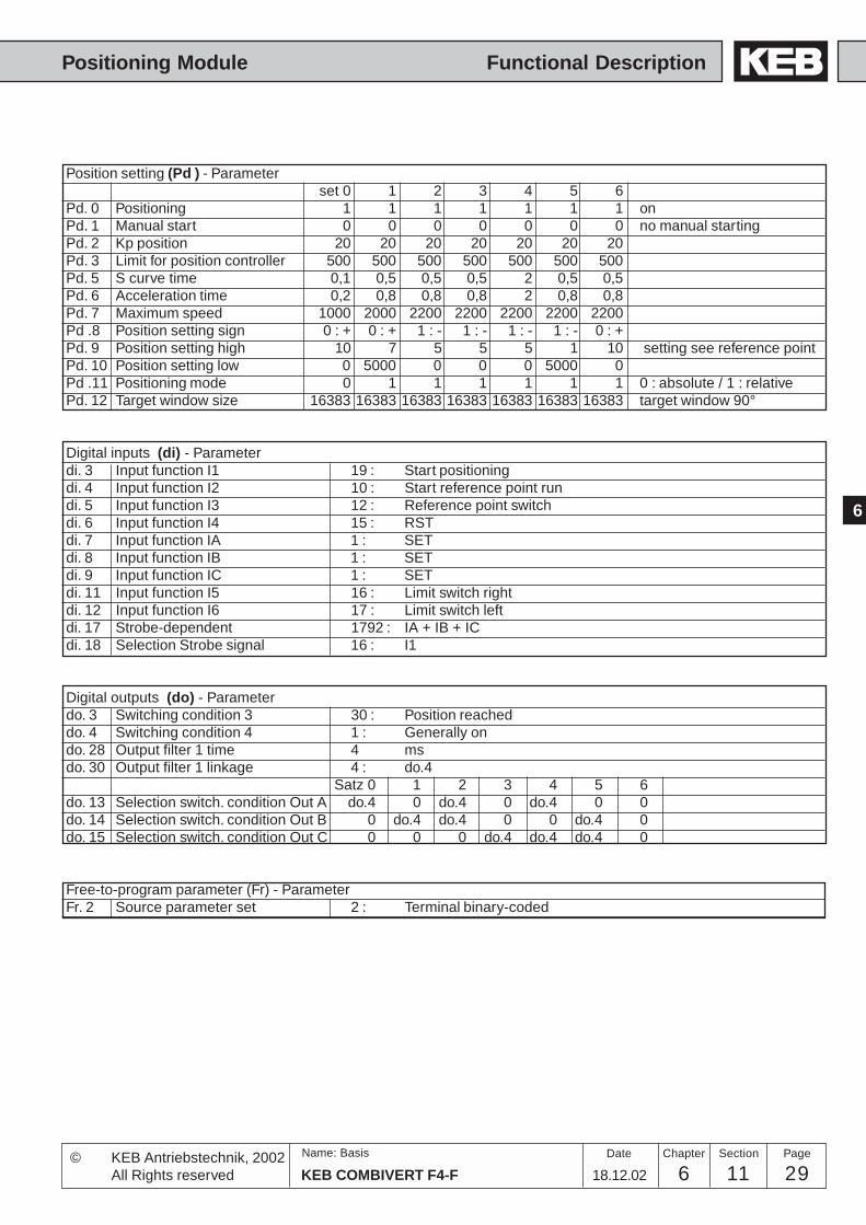
296 11 29KEB COMBIVERT F4-F
Name: Basis
18.12.02
6
Section PageDate© KEB Antriebstechnik, 2002All Rights reserved
Chapter
Functional DescriptionPositioning Module
Position setting (Pd ) - Parameterset 0 1 2 3 4 5 6
Pd. 0 Positioning 1 1 1 1 1 1 1 onPd. 1 Manual start 0 0 0 0 0 0 0 no manual startingPd. 2 Kp position 20 20 20 20 20 20 20Pd. 3 Limit for position controller 500 500 500 500 500 500 500Pd. 5 S curve time 0,1 0,5 0,5 0,5 2 0,5 0,5Pd. 6 Acceleration time 0,2 0,8 0,8 0,8 2 0,8 0,8Pd. 7 Maximum speed 1000 2000 2200 2200 2200 2200 2200Pd .8 Position setting sign 0 : + 0 : + 1 : - 1 : - 1 : - 1 : - 0 : +Pd. 9 Position setting high 10 7 5 5 5 1 10 setting see reference pointPd. 10 Position setting low 0 5000 0 0 0 5000 0Pd .11 Positioning mode 0 1 1 1 1 1 1 0 : absolute / 1 : relativePd. 12 Target window size 16383 16383 16383 16383 16383 16383 16383 target window 90°
Digital inputs (di) - Parameterdi. 3 Input function I1 19 : Start positioningdi. 4 Input function I2 10 : Start reference point rundi. 5 Input function I3 12 : Reference point switchdi. 6 Input function I4 15 : RSTdi. 7 Input function IA 1 : SETdi. 8 Input function IB 1 : SETdi. 9 Input function IC 1 : SETdi. 11 Input function I5 16 : Limit switch rightdi. 12 Input function I6 17 : Limit switch leftdi. 17 Strobe-dependent 1792 : IA + IB + ICdi. 18 Selection Strobe signal 16 : I1
Digital outputs (do) - Parameterdo. 3 Switching condition 3 30 : Position reacheddo. 4 Switching condition 4 1 : Generally ondo. 28 Output filter 1 time 4 msdo. 30 Output filter 1 linkage 4 : do.4
Satz 0 1 2 3 4 5 6do. 13 Selection switch. condition Out A do.4 0 do.4 0 do.4 0 0do. 14 Selection switch. condition Out B 0 do.4 do.4 0 0 do.4 0do. 15 Selection switch. condition Out C 0 0 0 do.4 do.4 do.4 0
Free-to-program parameter (Fr) - ParameterFr. 2 Source parameter set 2 : Terminal binary-coded
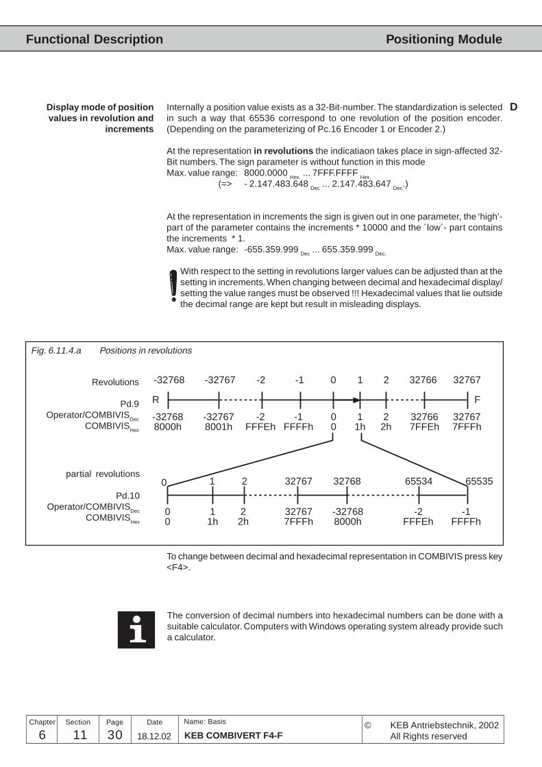
6 11 KEB COMBIVERT F4-F30Name: Basis
18.12.02
Chapter Section Page Date © KEB Antriebstechnik, 2002All Rights reserved
Functional Description Positioning Module
Fig. 6.11.4.a Positions in revolutions
00
-2FFFEh
-327688000h
327677FFFh
00
11h
22h
327667FFEh
R F
327677FFFh
-327688000h
-2FFFEh
-1FFFFh
0-2-32768 32766 32767
-1FFFFh
-1
11h
1
-327678001h
-32767
22h
2
0 327671 2 32768 65534 65535
Revolutions
Pd.9Operator/COMBIVIS
Dec
COMBIVISHex
partial revolutions
Pd.10Operator/COMBIVIS
Dec
COMBIVISHex
The conversion of decimal numbers into hexadecimal numbers can be done with asuitable calculator. Computers with Windows operating system already provide sucha calculator.
To change between decimal and hexadecimal representation in COMBIVIS press key<F4>.
Internally a position value exists as a 32-Bit-number. The standardization is selectedin such a way that 65536 correspond to one revolution of the position encoder.(Depending on the parameterizing of Pc.16 Encoder 1 or Encoder 2.)
At the representation in revolutions the indicatiaon takes place in sign-affected 32-Bit numbers. The sign parameter is without function in this modeMax. value range: 8000.0000
Hex. ... 7FFF.FFFF
Hex.
(=> - 2.147.483.648 Dec
... 2.147.483.647 Dec
.)
At the representation in increments the sign is given out in one parameter, the ‘high’-part of the parameter contains the increments * 10000 and the ´low´- part containsthe increments * 1.Max. value range: -655.359.999
Dec ... 655.359.999
Dec.
With respect to the setting in revolutions larger values can be adjusted than at thesetting in increments. When changing between decimal and hexadecimal display/setting the value ranges must be observed !!! Hexadecimal values that lie outsidethe decimal range are kept but result in misleading displays.
DDisplay mode of positionvalues in revolution and
increments
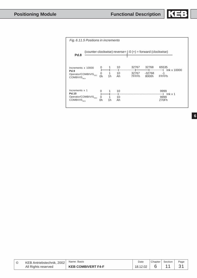
316 11 31KEB COMBIVERT F4-F
Name: Basis
18.12.02
6
Section PageDate© KEB Antriebstechnik, 2002All Rights reserved
Chapter
Functional DescriptionPositioning Module
Fig. 6.11.5 Positions in increments
0
00h
1
11h
10
10Ah
32767
327677FFFh
32768
-327688000h
65535
-1FFFFh
Ink x 10000
0
00h
1
11h
10
10Ah
9999
9999270Fh
Ink x 1
Increments x 10000Pd.9Operator/COMBIVISDEZ
COMBIVISHEX
0 (+) = forward (clockwise)(counter-clockwise) reverse= (-Pd.8
Increments x 1Pd.10Operator/COMBIVISDEZ
COMBIVISHEX
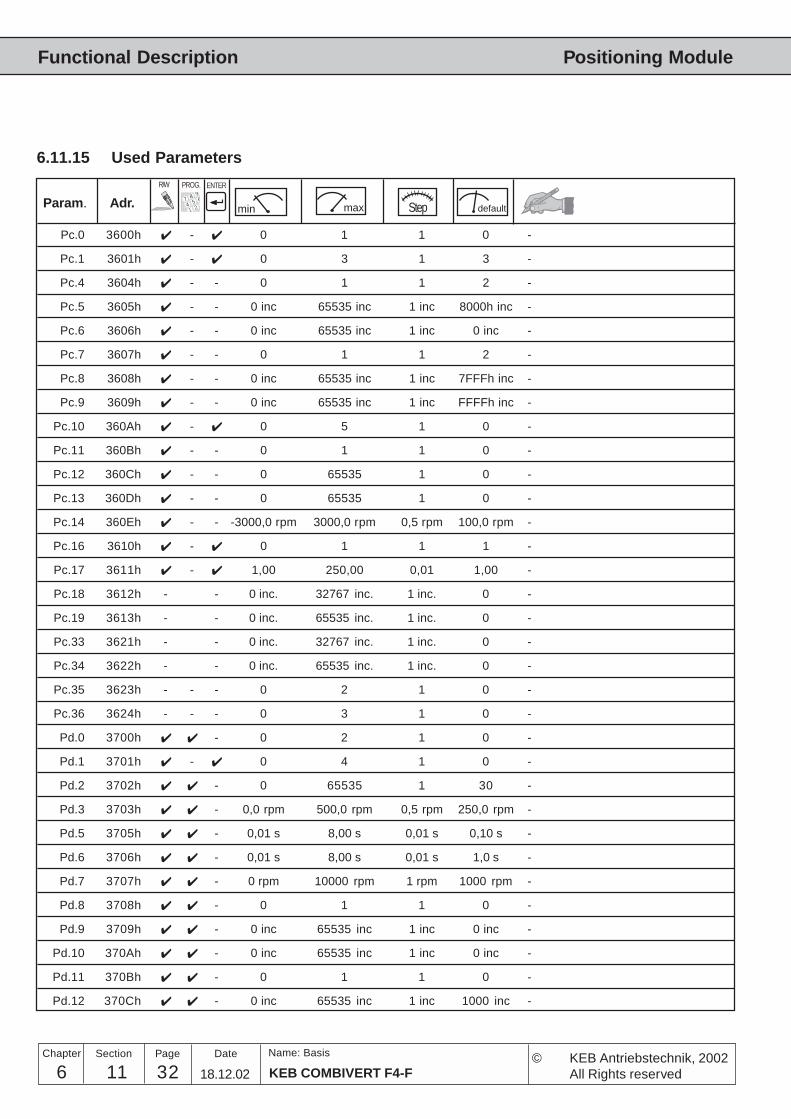
6 11 KEB COMBIVERT F4-F32Name: Basis
18.12.02
Chapter Section Page Date © KEB Antriebstechnik, 2002All Rights reserved
Functional Description Positioning Module
Param. Adr. min max default
ENTERPROG.R/W
Step
Pc.0 3600h - 0 1 1 0 -
Pc.1 3601h - 0 3 1 3 -
Pc.4 3604h - - 0 1 1 2 -
Pc.5 3605h - - 0 inc 65535 inc 1 inc 8000h inc -
Pc.6 3606h - - 0 inc 65535 inc 1 inc 0 inc -
Pc.7 3607h - - 0 1 1 2 -
Pc.8 3608h - - 0 inc 65535 inc 1 inc 7FFFh inc -
Pc.9 3609h - - 0 inc 65535 inc 1 inc FFFFh inc -
Pc.10 360Ah - 0 5 1 0 -
Pc.11 360Bh - - 0 1 1 0 -
Pc.12 360Ch - - 0 65535 1 0 -
Pc.13 360Dh - - 0 65535 1 0 -
Pc.14 360Eh - - -3000,0 rpm 3000,0 rpm 0,5 rpm 100,0 rpm -
Pc.16 3610h - 0 1 1 1 -
Pc.17 3611h - 1,00 250,00 0,01 1,00 -
Pc.18 3612h - - 0 inc. 32767 inc. 1 inc. 0 -
Pc.19 3613h - - 0 inc. 65535 inc. 1 inc. 0 -
Pc.33 3621h - - 0 inc. 32767 inc. 1 inc. 0 -
Pc.34 3622h - - 0 inc. 65535 inc. 1 inc. 0 -
Pc.35 3623h - - - 0 2 1 0 -
Pc.36 3624h - - - 0 3 1 0 -
Pd.0 3700h - 0 2 1 0 -
Pd.1 3701h - 0 4 1 0 -
Pd.2 3702h - 0 65535 1 30 -
Pd.3 3703h - 0,0 rpm 500,0 rpm 0,5 rpm 250,0 rpm -
Pd.5 3705h - 0,01 s 8,00 s 0,01 s 0,10 s -
Pd.6 3706h - 0,01 s 8,00 s 0,01 s 1,0 s -
Pd.7 3707h - 0 rpm 10000 rpm 1 rpm 1000 rpm -
Pd.8 3708h - 0 1 1 0 -
Pd.9 3709h - 0 inc 65535 inc 1 inc 0 inc -
Pd.10 370Ah - 0 inc 65535 inc 1 inc 0 inc -
Pd.11 370Bh - 0 1 1 0 -
Pd.12 370Ch - 0 inc 65535 inc 1 inc 1000 inc -
6.11.15 Used Parameters

6 12 1KEB COMBIVERT F4-F
Name: Basis
18.12.02
Functional Description
Chapter Section PageDate© KEB Antriebstechnik, 2002All Rights reserved
1. Introduction
2. Summary
3. Hardware
4. Operation
5. Parameter
6. Functions
7. Start-up
8. Special Operation
9. Error Assistance
10. Project Planning
11. Networks
12. Applications
13. Annex
6.1 Operating and Unit Data
6.2 Analog In- and Outputs
6.3 Digital In- and Outputs
6.4 Set Value and RampAdjustment
6.5 Motor Data and ControllerAdjustment
6.6 Keep on Running Functions
6.7 Parameter Sets
6.8 Special Functions
6.9 Encoder Interface
6.10 Synchronous Control
6.11 Positioning Module
6.12 CP-Parameter Definition 6.12.1 Survey ................................... 36.12.2 Assignment of CP-Parameter 46.12.3 Start Parameters ................... 46.12.4 Example ................................. 56.12.5 Used Parameters ................... 5

6 12 KEB COMBIVERT F4-F2Name: Basis
18.12.02
Chapter Section Page Date © KEB Antriebstechnik, 2002All Rights reserved
Functional Description CP-Parameter Definition
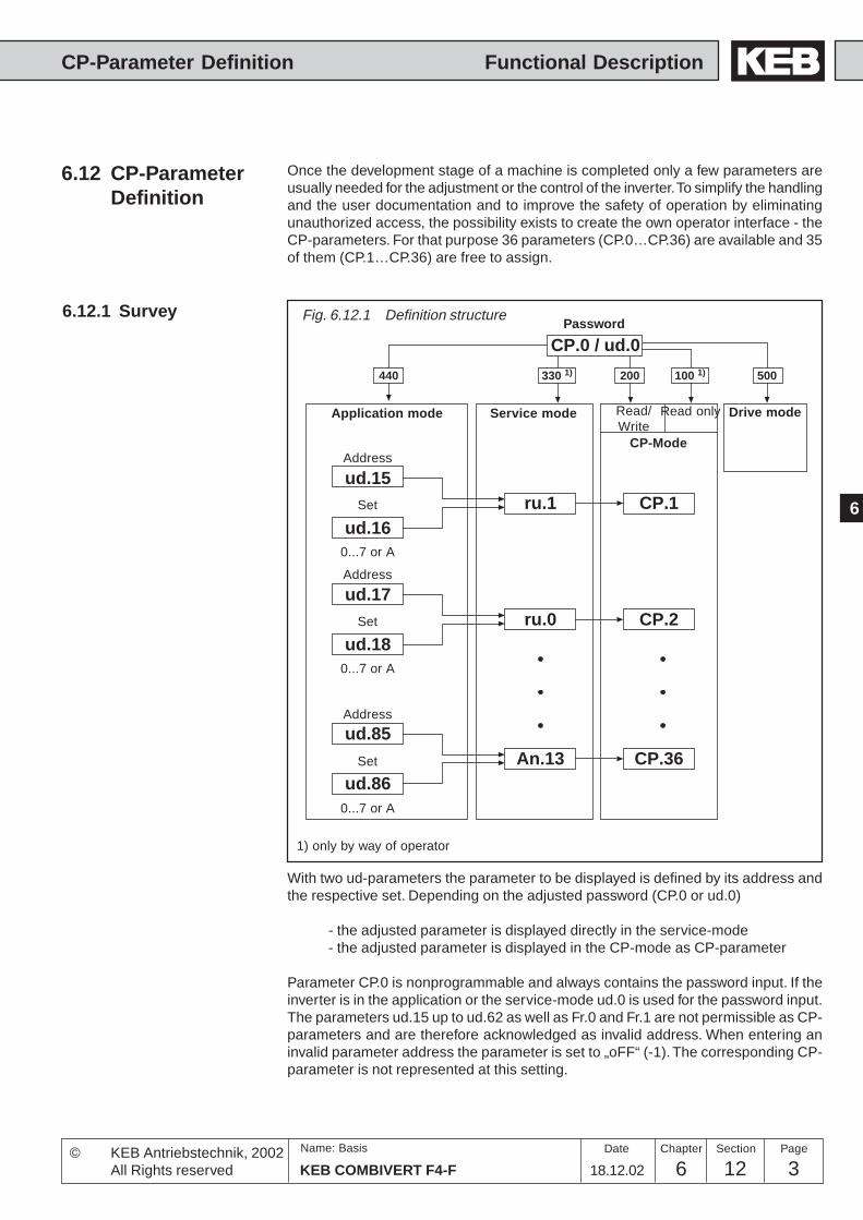
36 12 3KEB COMBIVERT F4-F
Name: Basis
18.12.02
6
Section PageDate© KEB Antriebstechnik, 2002All Rights reserved
Chapter
Functional DescriptionCP-Parameter Definition
6.12 CP-ParameterDefinition
6.12.1 Survey Fig. 6.12.1 Definition structure
Once the development stage of a machine is completed only a few parameters areusually needed for the adjustment or the control of the inverter. To simplify the handlingand the user documentation and to improve the safety of operation by eliminatingunauthorized access, the possibility exists to create the own operator interface - theCP-parameters. For that purpose 36 parameters (CP.0…CP.36) are available and 35of them (CP.1…CP.36) are free to assign.
With two ud-parameters the parameter to be displayed is defined by its address andthe respective set. Depending on the adjusted password (CP.0 or ud.0)
- the adjusted parameter is displayed directly in the service-mode- the adjusted parameter is displayed in the CP-mode as CP-parameter
Parameter CP.0 is nonprogrammable and always contains the password input. If theinverter is in the application or the service-mode ud.0 is used for the password input.The parameters ud.15 up to ud.62 as well as Fr.0 and Fr.1 are not permissible as CP-parameters and are therefore acknowledged as invalid address. When entering aninvalid parameter address the parameter is set to „oFF“ (-1). The corresponding CP-parameter is not represented at this setting.
CP.0 / ud.0
ud.15
ud.16ru.1
ud.17
ud.18ru.0
ud.85
ud.86An.13
CP.1
CP.2
CP.36
440 330 1) 200 100 1) 500
Password
Application mode Service mode Read/Write
Read only Drive mode
CP-ModeAddress
Set
0...7 or A
Address
Set
0...7 or A
Address
Set
0...7 or A
1) only by way of operator
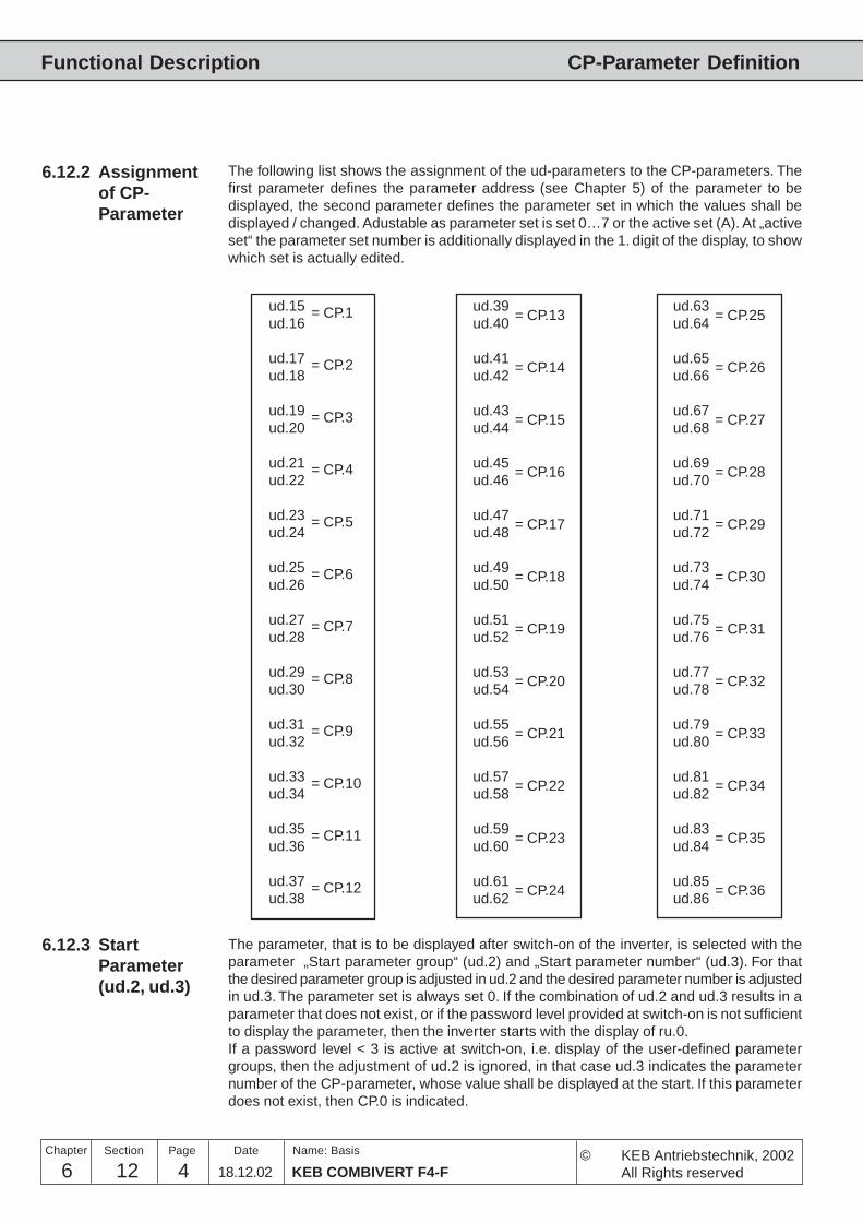
6 12 KEB COMBIVERT F4-F4Name: Basis
18.12.02
Chapter Section Page Date © KEB Antriebstechnik, 2002All Rights reserved
Functional Description CP-Parameter Definition
= CP.1
= CP.2
= CP.3
= CP.4
= CP.5
= CP.6
= CP.7
= CP.8
= CP.9
= CP.10
= CP.11
= CP.12
ud.15ud.16
ud.17ud.18
ud.19ud.20
ud.21ud.22
ud.23ud.24
ud.25ud.26
ud.27ud.28
ud.29ud.30
ud.31ud.32
ud.33ud.34
ud.35ud.36
ud.37ud.38
= CP.13
= CP.14
= CP.15
= CP.16
= CP.17
= CP.18
= CP.19
= CP.20
= CP.21
= CP.22
= CP.23
= CP.24
ud.39ud.40
ud.41ud.42
ud.43ud.44
ud.45ud.46
ud.47ud.48
ud.49ud.50
ud.51ud.52
ud.53ud.54
ud.55ud.56
ud.57ud.58
ud.59ud.60
ud.61ud.62
= CP.25
= CP.26
= CP.27
= CP.28
= CP.29
= CP.30
= CP.31
= CP.32
= CP.33
= CP.34
= CP.35
= CP.36
ud.63ud.64
ud.65ud.66
ud.67ud.68
ud.69ud.70
ud.71ud.72
ud.73ud.74
ud.75ud.76
ud.77ud.78
ud.79ud.80
ud.81ud.82
ud.83ud.84
ud.85ud.86
6.12.2 Assignmentof CP-Parameter
The following list shows the assignment of the ud-parameters to the CP-parameters. Thefirst parameter defines the parameter address (see Chapter 5) of the parameter to bedisplayed, the second parameter defines the parameter set in which the values shall bedisplayed / changed. Adustable as parameter set is set 0…7 or the active set (A). At „activeset“ the parameter set number is additionally displayed in the 1. digit of the display, to showwhich set is actually edited.
6.12.3 StartParameter(ud.2, ud.3)
The parameter, that is to be displayed after switch-on of the inverter, is selected with theparameter „Start parameter group“ (ud.2) and „Start parameter number“ (ud.3). For thatthe desired parameter group is adjusted in ud.2 and the desired parameter number is adjustedin ud.3. The parameter set is always set 0. If the combination of ud.2 and ud.3 results in aparameter that does not exist, or if the password level provided at switch-on is not sufficientto display the parameter, then the inverter starts with the display of ru.0.If a password level < 3 is active at switch-on, i.e. display of the user-defined parametergroups, then the adjustment of ud.2 is ignored, in that case ud.3 indicates the parameternumber of the CP-parameter, whose value shall be displayed at the start. If this parameterdoes not exist, then CP.0 is indicated.
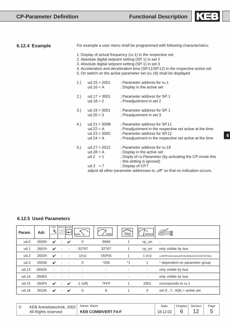
56 12 5KEB COMBIVERT F4-F
Name: Basis
18.12.02
6
Section PageDate© KEB Antriebstechnik, 2002All Rights reserved
Chapter
Functional DescriptionCP-Parameter Definition
Param. Adr. min max default
ENTERPROG.R/W
Step
6.12.4 Example For example a user menu shall be programmed with following characteristics:
1. Display of actual frequency (ru.1) in the respective set2. Absolute digital setpoint setting (SP. 1) in set 23. Absolute digital setpoint setting (SP. 1) in set 34. Acceleration and deceleration time (SP.11/SP.12) in the respective active set5. On switch on the active parameter set (ru.18) shall be displayed
1.) ud.15 = 2001 ; Parameter address for ru.1ud.16 = A ; Display in the active set
2.) ud.17 = 3001 ; Parameter address for SP. 1ud.18 = 2 ; Preadjustment in set 2
3.) ud.19 = 3001 ; Parameter address for SP. 1ud.20 = 3 ; Preadjustment in set 3
4.) ud.21 = 300B ; Parameter address for SP.11ud.22 = A ; Preadjustment in the respective set active at the timeud.23 = 300C ; Parameter address for SP.12ud.24 = A ; Preadjustment in the respective set active at the time
5.) ud.27 = 2012 ; Parameter address for ru.18ud.28 = A ; Display in the active setud.2 = 1 ; Disply of ru-Parameter (by activating the CP-mode this
; this setting is ignored)ud.3 = 7 ; Display of CP.7adjust all other parameter addresses to „off“ so that no indication occurs.
6.12.5 Used Parameters
ud.0 2600h - 0 9999 1 cp_on -
ud.1 2601h - - -32767 32767 1 cp_on only visible by bus
ud.2 2602h - - 1(ru) 16(Pd) 1 1 (ru) ru/SP/Pn/dr/cs/ds/ud/Fr/An/di/do/LE/In/Sn/Pc/PdAA
ud.3 2603h - - 0 *255 *1 1 * dependent on parameter group
ud.13 260Dh - - - - - - - only visible by bus
ud.14 260Eh - - - - - - - only visible by bus
ud.15 260Fh - -1 (off) 7FFF 1 2001 corresponds to ru.1
ud.16 2610h - 0 8 1 0 set 0...7; A(8) = active set
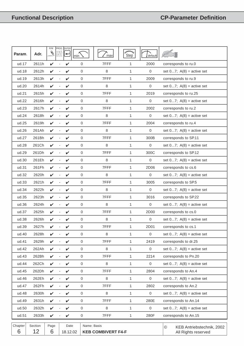
6 12 KEB COMBIVERT F4-F6Name: Basis
18.12.02
Chapter Section Page Date © KEB Antriebstechnik, 2002All Rights reserved
Functional Description CP-Parameter Definition
Param. Adr. min max default
ENTERPROG.R/W
Step
ud.17 2611h - 0 7FFF 1 2000 corresponds to ru.0
ud.18 2612h - 0 8 1 0 set 0...7; A(8) = active set
ud.19 2613h - 0 7FFF 1 2009 corresponds to ru.9
ud.20 2614h - 0 8 1 0 set 0...7; A(8) = active set
ud.21 2615h - 0 7FFF 1 2019 corresponds to ru.25
ud.22 2616h - 0 8 1 0 set 0...7; A(8) = active set
ud.23 2617h - 0 7FFF 1 2002 corresponds to ru.2
ud.24 2618h - 0 8 1 0 set 0...7; A(8) = active set
ud.25 2619h - 0 7FFF 1 2004 corresponds to ru.4
ud.26 261Ah - 0 8 1 0 set 0...7; A(8) = active set
ud.27 261Bh - 0 7FFF 1 300B corresponds to SP.11
ud.28 261Ch - 0 8 1 0 set 0...7; A(8) = active set
ud.29 261Dh - 0 7FFF 1 300C corresponds to SP.12
ud.30 261Eh - 0 8 1 0 set 0...7; A(8) = active set
ud.31 261Fh - 0 7FFF 1 2D06 corresponds to cs.6
ud.32 2620h - 0 8 1 0 set 0...7; A(8) = active set
ud.33 2621h - 0 7FFF 1 3005 corresponds to SP.5
ud.34 2622h - 0 8 1 0 set 0...7; A(8) = active set
ud.35 2623h - 0 7FFF 1 3016 corresponds to SP.22
ud.36 2624h - 0 8 1 0 set 0...7; A(8) = active set
ud.37 2625h - 0 7FFF 1 2D00 corresponds to cs.0
ud.38 2626h - 0 8 1 0 set 0...7; A(8) = active set
ud.39 2627h - 0 7FFF 1 2D01 corresponds to cs.1
ud.40 2628h - 0 8 1 0 set 0...7; A(8) = active set
ud.41 2629h - 0 7FFF 1 2419 corresponds to dr.25
ud.42 262Ah - 0 8 1 0 set 0...7; A(8) = active set
ud.43 262Bh - 0 7FFF 1 2214 corresponds to Pn.20
ud.44 262Ch - 0 8 1 0 set 0...7; A(8) = active set
ud.45 262Dh - 0 7FFF 1 2804 corresponds to An.4
ud.46 262Eh - 0 8 1 0 set 0...7; A(8) = active set
ud.47 262Fh - 0 7FFF 1 2802 corresponds to An.2
ud.48 2630h - 0 8 1 0 set 0...7; A(8) = active set
ud.49 2631h - 0 7FFF 1 280E corresponds to An.14
ud.50 2632h - 0 8 1 0 set 0...7; A(8) = active set
ud.51 2633h - 0 7FFF 1 280F corresponds to An.15
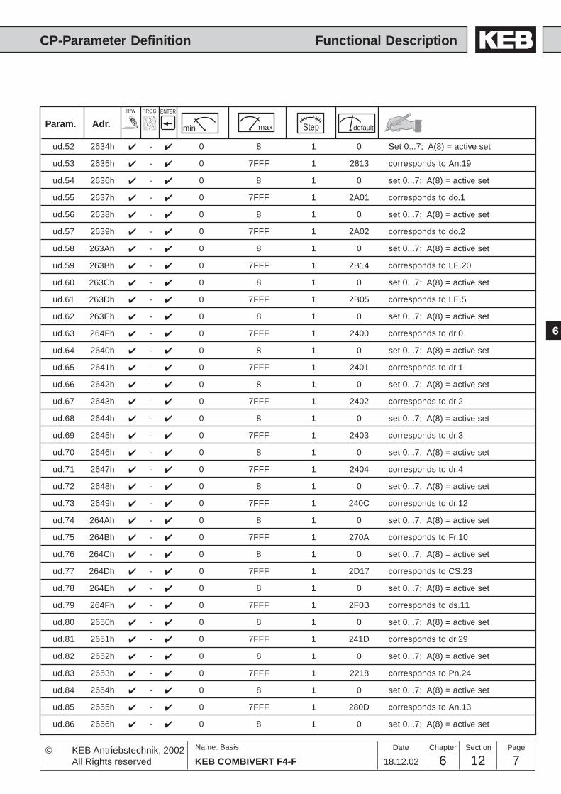
76 12 7KEB COMBIVERT F4-F
Name: Basis
18.12.02
6
Section PageDate© KEB Antriebstechnik, 2002All Rights reserved
Chapter
Functional DescriptionCP-Parameter Definition
Param. Adr. min max default
ENTERPROG.R/W
Step
ud.52 2634h - 0 8 1 0 Set 0...7; A(8) = active set
ud.53 2635h - 0 7FFF 1 2813 corresponds to An.19
ud.54 2636h - 0 8 1 0 set 0...7; A(8) = active set
ud.55 2637h - 0 7FFF 1 2A01 corresponds to do.1
ud.56 2638h - 0 8 1 0 set 0...7; A(8) = active set
ud.57 2639h - 0 7FFF 1 2A02 corresponds to do.2
ud.58 263Ah - 0 8 1 0 set 0...7; A(8) = active set
ud.59 263Bh - 0 7FFF 1 2B14 corresponds to LE.20
ud.60 263Ch - 0 8 1 0 set 0...7; A(8) = active set
ud.61 263Dh - 0 7FFF 1 2B05 corresponds to LE.5
ud.62 263Eh - 0 8 1 0 set 0...7; A(8) = active set
ud.63 264Fh - 0 7FFF 1 2400 corresponds to dr.0
ud.64 2640h - 0 8 1 0 set 0...7; A(8) = active set
ud.65 2641h - 0 7FFF 1 2401 corresponds to dr.1
ud.66 2642h - 0 8 1 0 set 0...7; A(8) = active set
ud.67 2643h - 0 7FFF 1 2402 corresponds to dr.2
ud.68 2644h - 0 8 1 0 set 0...7; A(8) = active set
ud.69 2645h - 0 7FFF 1 2403 corresponds to dr.3
ud.70 2646h - 0 8 1 0 set 0...7; A(8) = active set
ud.71 2647h - 0 7FFF 1 2404 corresponds to dr.4
ud.72 2648h - 0 8 1 0 set 0...7; A(8) = active set
ud.73 2649h - 0 7FFF 1 240C corresponds to dr.12
ud.74 264Ah - 0 8 1 0 set 0...7; A(8) = active set
ud.75 264Bh - 0 7FFF 1 270A corresponds to Fr.10
ud.76 264Ch - 0 8 1 0 set 0...7; A(8) = active set
ud.77 264Dh - 0 7FFF 1 2D17 corresponds to CS.23
ud.78 264Eh - 0 8 1 0 set 0...7; A(8) = active set
ud.79 264Fh - 0 7FFF 1 2F0B corresponds to ds.11
ud.80 2650h - 0 8 1 0 set 0...7; A(8) = active set
ud.81 2651h - 0 7FFF 1 241D corresponds to dr.29
ud.82 2652h - 0 8 1 0 set 0...7; A(8) = active set
ud.83 2653h - 0 7FFF 1 2218 corresponds to Pn.24
ud.84 2654h - 0 8 1 0 set 0...7; A(8) = active set
ud.85 2655h - 0 7FFF 1 280D corresponds to An.13
ud.86 2656h - 0 8 1 0 set 0...7; A(8) = active set

6 12 KEB COMBIVERT F4-F8Name: Basis
18.12.02
Chapter Section Page Date © KEB Antriebstechnik, 2002All Rights reserved
Functional Description CP-Parameter Definition
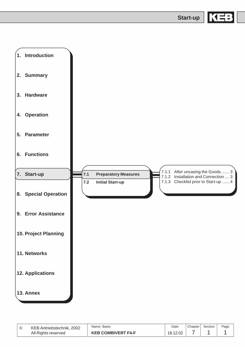
7 1 1KEB COMBIVERT F4-F
Name: Basis
Start-up
1. Introduction
2. Summary
3. Hardware
4. Operation
5. Parameter
6. Functions
7. Start-up
8. Special Operation
9. Error Assistance
10. Project Planning
11. Networks
12. Applications
13. Annex
7.1 Preparatory Measures
7.2 Initial Start-up
Chapter Section PageDate
18.12.02© KEB Antriebstechnik, 2002
All Rights reserved
7.1.1 After uncasing the Goods ....... 37.1.2 Installation and Connection .... 37.1.3 Checklist prior to Start-up ...... 4

7 1 KEB COMBIVERT F4-F2Name: Basis
Start-up
Chapter Section Page Date
18.12.02© KEB Antriebstechnik, 2002
All Rights reserved
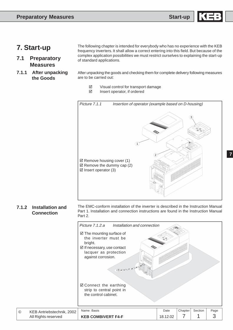
37 1 3KEB COMBIVERT F4-F
Name: Basis
7
Start-up
Section PageDate Chapter
18.12.02© KEB Antriebstechnik, 2002
All Rights reserved
POWERXXXXXXXXXXXX
INPUTOUTPUT
KEB Antriebstechnik
Karl E. Brinkmann GmbH
D-32677 Barntrup
Made in Germany
VOLTAGECYCLE XXXXXXXXXXX
XXXXXXXXXXX
VOLTAGECURRENTVER-NO.
ART-NO.SER-NO.
XXXXXXXXXXXXXXX˜
95000001/XXXXXXX
XX.F4.XXX-XXXX
XXXXXXXXXXXX
XXXXXXXXXX
AC-MOT. 4,0 KW, 2/4 P, 50/60 HZ
L1 L2 L3
2
3
STARTSTOP
ENTERF/R
FUNC.SPEED
electronic
ANTRIEBSTECHNI
1
POWERXXXXXXXXXXXX
INPUTOUTPUT
KEB Antriebstechnik
Karl E. Brinkmann GmbH
D-32677 Barntrup
Made in Germany
VOLTAGECYCLE XXXXXXXXXXX
XXXXXXXXXXX
VOLTAGECURRENTVER-NO.
ART-NO.SER-NO.
XXXXXXXXXXXXXXX˜
95000001/XXXXXXX
XX.F4.XXX-XXXX
XXXXXXXXXXXX
XXXXXXXXXX
AC-MOT. 4,0 KW, 2/4 P, 50/60 HZ
L1 L2 L3
STARTSTOP
ENTERF/R
FUNC.SPEED
electronic
ANTRIEBSTECHNI
7.1.1 After unpackingthe Goods
7.1 PreparatoryMeasures
7.1.2 Installation andConnection
Picture 7.1.1 Insertion of operator (example based on D-housing)
7. Start-up The following chapter is intended for everybody who has no experience with the KEBfrequency inverters. It shall allow a correct entering into this field. But because of thecomplex application possibilities we must restrict ourselves to explaining the start-upof standard applications.
After unpacking the goods and checking them for complete delivery following measuresare to be carried out:
Visual control for transport damageInsert operator, if ordered
Remove housing cover (1) Remove the dummy cap (2) Insert operator (3)
Picture 7.1.2.a Installation and connection
The EMC-conform installation of the inverter is described in the Instruction ManualPart 1. Installation and connection instructions are found in the Instruction ManualPart 2.
The mounting surface ofthe inver ter must bebright.If necessary, use contactlacquer as protectionagainst corrosion.
Connect the earthingstrip to central point inthe control cabinet.
Preparatory Measures

7 1 KEB COMBIVERT F4-F4Name: Basis
Start-up
Chapter Section Page Date
18.12.02© KEB Antriebstechnik, 2002
All Rights reserved
7.1.3 Checklist prior toStart-up
Before switching on the inverter go through the following checklist.
Is the inverter firmly bolted in the control cabinet?
Is there enough space to ensure sufficient air circulation?
Are mains and motor cables as well as the control cables installedseparately from each other?
Are the inverters connected to the correct supply voltage?
Are all mass and earthing cables attached and well contacted?
Ensure that mains and motor cables are not interchanged as thatwill lead to the destruction of the inverter!
Is the motor connected in-phase?
Check tacho, initiator and encoder for firm attachment and correctconnection!
Check, whether all power and control cables are firmly in place!
Remove any tools from the control cabinet!
Attach all covers and protective caps to ensure that all live partsare secured against direct contact.
When using measuring instruments or computers an isolatingtransformer should be used, if not, make sure that the equipotenialbonding between the supply lines is guaranteed!
Open the control release of the inverter to avoid the unintendedstarting of the machine.
Preparatory Measures
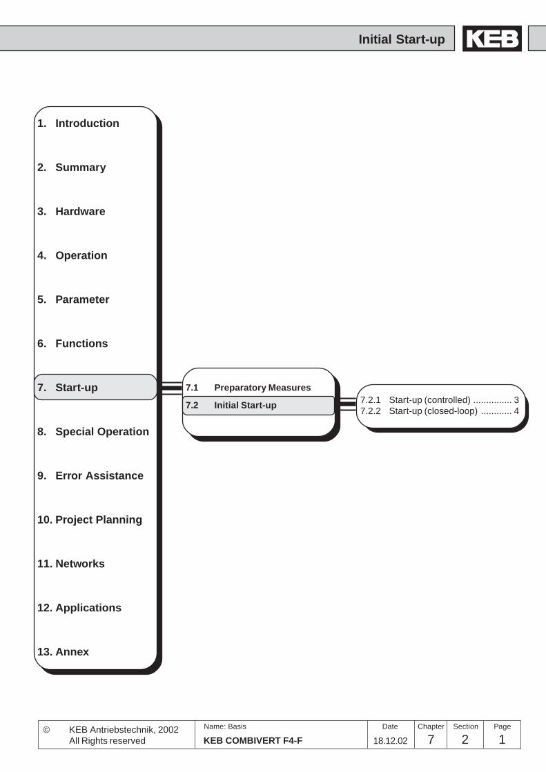
7 2 1KEB COMBIVERT F4-F
Name: Basis
Initial Start-up
1. Introduction
2. Summary
3. Hardware
4. Operation
5. Parameter
6. Functions
7. Start-up
8. Special Operation
9. Error Assistance
10. Project Planning
11. Networks
12. Applications
13. Annex
7.1 Preparatory Measures
7.2 Initial Start-up
Chapter Section PageDate
18.12.02© KEB Antriebstechnik, 2002
All Rights reserved
7.2.1 Start-up (controlled) ............... 37.2.2 Start-up (closed-loop) ............ 4

7 2 KEB COMBIVERT F4-F2Name: Basis
Initial Start-up
Chapter Section Page Date
18.12.02© KEB Antriebstechnik, 2002
All Rights reserved
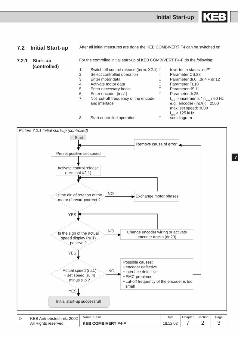
37 2 3KEB COMBIVERT F4-F
Name: Basis
7
Initial Start-up
Section PageDate Chapter
18.12.02© KEB Antriebstechnik, 2002
All Rights reserved
After all initial measures are done the KEB COMBIVERT F4 can be switched on.
Picture 7.2.1 Initial start-up (controlled)
For the controlled initial start-up of KEB COMBIVERT F4-F do the following:
1. Switch off control release (term. X2.1) ⇒ Inverter in status „noP“2. Select controlled operation ⇒ Parameter CS.233. Enter motor data ⇒ Parameter dr.0...dr.4 + dr.124. Activate motor data ⇒ Parameter Fr.105. Enter necessary boost ⇒ Parameter dS.116. Enter encoder (inc/r) ⇒ Parameter dr.257. Not cut-off frequency of the encoder ⇒ f
limit > increments * n
max / 60 Hz
and interface e.g. encoder (inc/r): 2500max. set speed: 3000flimit
> 125 kHz8. Start controlled operation ⇒ see diagram
Start
Preset positive set speed
Remove cause of error
Activate control release(terminal X2.1)
Is the dir. of rotation of themotor (forward)correct ?
Exchange motor phasesNO
NO
NOIs the sign of the actualspeed display (ru.1)
positive ?
Actual speed (ru.1)= set speed (ru.4)
minus slip ?
Change encoder wiring or activateencoder tracks (dr.29)
Possible causes:• encoder defective• interface defective• EMC-problems• cut-off frequency of the encoder is too small
YES
YES
YES
Initial start-up successful!
7.2 Initial Start-up
7.2.1 Start-up(controlled)
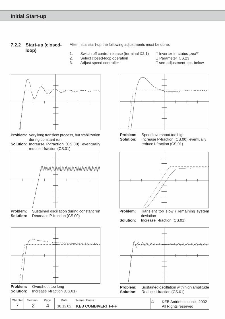
7 2 KEB COMBIVERT F4-F4Name: Basis
Initial Start-up
Chapter Section Page Date
18.12.02© KEB Antriebstechnik, 2002
All Rights reserved
After initial start-up the following adjustments must be done:
1. Switch off control release (terminal X2.1) ⇒ Inverter in status „noP“2. Select closed-loop operation ⇒ Parameter CS.233. Adjust speed controller ⇒ see adjustment tips below
7.2.2 Start-up (closed-loop)
Problem: Sustained oscillation with high amplitudeSolution: Reduce I-fraction (CS.01)
Problem: Very long transient process, but stabilizationduring constant run
Solution: Increase P-fraction (CS.00); eventuallyreduce I-fraction (CS.01)
Problem: Speed overshoot too highSolution: Increase P-fraction (CS.00); eventually
reduce I-fraction (CS.01)
Problem: Sustained oscillation during constant runSolution: Decrease P-fraction (CS.00)
Problem: Transient too slow / remaining systemdeviation
Solution: Increase I-fraction (CS.01)
Problem: Overshoot too longSolution: Increase I-fraction (CS.01)
8 1 1KEB COMBIVERT F4-FName: Basis
1. Introduction
2. Summary
3. Hardware
4. Operation
5. Parameter
6. Functions
7. Start-up
8. Special Operation
9. Error Assistance
10. Project Planning
11. Networks
12. Applications
13. Annex
Is currently updated andwill soon be available onInternet http://www.keb.de
Special Operation
Chapter Section PageDate
18.12.02© KEB Antriebstechnik, 2002
All Rights reserved

8 1 KEB COMBIVERT F4-F2Name: Basis
Special Operation
Chapter Section Page Date
18.12.02© KEB Antriebstechnik, 2002
All Rights reserved
8. SpecialOperation
9 1 1KEB COMBIVERT F4-F
Name: Basis
15.10.02
1. Introduction
2. Summary
3. Hardware
4. Operation
5. Parameter
6. Functions
7. Start-up
8. Special Operation
9. Error Assistance
10. Project Planning
11. Networks
12. Applications
13. Annex
9.1 Troubleshooting
Error Assistance
© KEB Antriebstechnik, 2002All Rights reserved
Chapter Section PageDate
9.1.1 General .................................. 39.1.2 Error Messages and their
Cause .................................... 3

9 1 KEB COMBIVERT F4-F2Name: Basis
15.10.02
Error Assistance
Chapter Section Page Date © KEB Antriebstechnik, 2002All Rights reserved
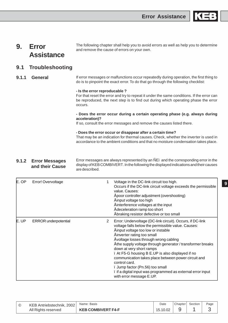
39 1 3KEB COMBIVERT F4-F
Name: Basis
15.10.02
9
Error Assistance
Section PageDate© KEB Antriebstechnik, 2002All Rights reserved
Chapter
9.1 Troubleshooting
9.1.1 General
9. ErrorAssistance
The following chapter shall help you to avoid errors as well as help you to determineand remove the cause of errors on your own.
If error messages or malfunctions occur repeatedly during operation, the first thing todo is to pinpoint the exact error. To do that go through the following checklist:
- Is the error reproducable ?For that reset the error and try to repeat it under the same conditions. If the error canbe reproduced, the next step is to find out during which operating phase the erroroccurs.
- Does the error occur during a certain operating phase (e.g. always duringacceleration)?If so, consult the error messages and remove the causes listed there.
- Does the error occur or disappear after a certain time?That may be an indication for thermal causes. Check, whether the inverter is used inaccordance to the ambient conditions and that no moisture condensation takes place.
9.1.2 Error Messagesand their Cause
Error messages are always represented by an ÑEì and the corresponding error in thedisplay of KEB COMBIVERT. In the following the displayed indications and their causesare described.
E. OP Error! Overvoltage 1 Voltage in the DC-link circuit too high.Occurs if the DC-link circuit voltage exceeds the permissiblevalue. Causes:Åpoor controller adjustment (overshooting)Åinput voltage too highÅinterference voltages at the inputÅdeceleration ramp too shortÅbraking resistor defective or too small
E. UP ERROR underpotential 2 Error: Undervoltage (DC-link circuit). Occurs, if DC-linkvoltage falls below the permissible value. Causes:Åinput voltage too low or instableÅinverter rating too smallÅvoltage losses through wrong cablingÅthe supply voltage through generator / transformer breaksdown at very short rampsï At F5-G housing B E.UP is also displayed if nocommunication takes place between power circuit andcontrol card.ï Jump factor (Pn.56) too smallï if a digital input was programmed as external error inputwith error message E.UP.
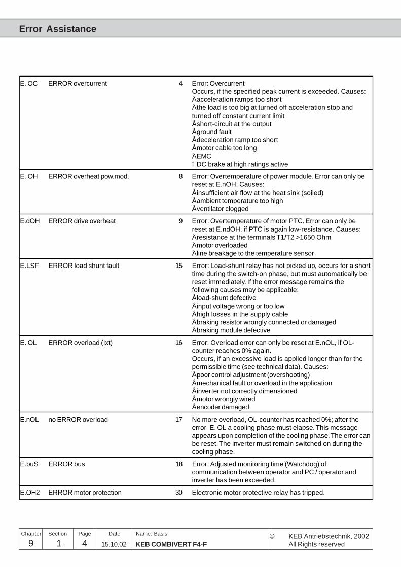
9 1 KEB COMBIVERT F4-F4Name: Basis
15.10.02
Error Assistance
Chapter Section Page Date © KEB Antriebstechnik, 2002All Rights reserved
E. OC ERROR overcurrent 4 Error: OvercurrentOccurs, if the specified peak current is exceeded. Causes:Åacceleration ramps too shortÅthe load is too big at turned off acceleration stop andturned off constant current limitÅshort-circuit at the outputÅground faultÅdeceleration ramp too shortÅmotor cable too longÅEMCï DC brake at high ratings active
E. OH ERROR overheat pow.mod. 8 Error: Overtemperature of power module. Error can only bereset at E.nOH. Causes:Åinsufficient air flow at the heat sink (soiled)Åambient temperature too highÅventilator clogged
E.dOH ERROR drive overheat 9 Error: Overtemperature of motor PTC. Error can only bereset at E.ndOH, if PTC is again low-resistance. Causes:Åresistance at the terminals T1/T2 >1650 OhmÅmotor overloadedÅline breakage to the temperature sensor
E.LSF ERROR load shunt fault 15 Error: Load-shunt relay has not picked up, occurs for a shorttime during the switch-on phase, but must automatically bereset immediately. If the error message remains thefollowing causes may be applicable:Åload-shunt defectiveÅinput voltage wrong or too lowÅhigh losses in the supply cableÅbraking resistor wrongly connected or damagedÅbraking module defective
E. OL ERROR overload (Ixt) 16 Error: Overload error can only be reset at E.nOL, if OL-counter reaches 0% again.Occurs, if an excessive load is applied longer than for thepermissible time (see technical data). Causes:Åpoor control adjustment (overshooting)Åmechanical fault or overload in the applicationÅinverter not correctly dimensionedÅmotor wrongly wiredÅencoder damaged
E.nOL no ERROR overload 17 No more overload, OL-counter has reached 0%; after theerror E. OL a cooling phase must elapse. This messageappears upon completion of the cooling phase. The error canbe reset. The inverter must remain switched on during thecooling phase.
E.buS ERROR bus 18 Error: Adjusted monitoring time (Watchdog) ofcommunication between operator and PC / operator andinverter has been exceeded.
E.OH2 ERROR motor protection 30 Electronic motor protective relay has tripped.
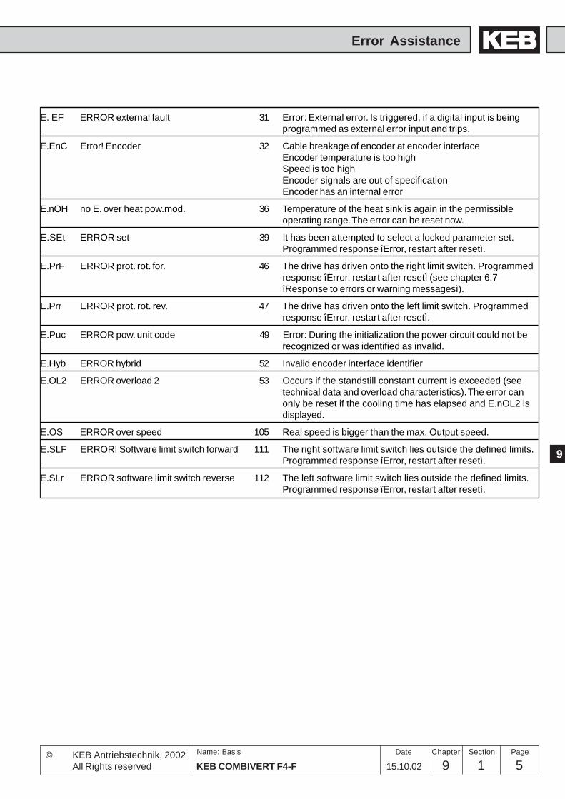
59 1 5KEB COMBIVERT F4-F
Name: Basis
15.10.02
9
Error Assistance
Section PageDate© KEB Antriebstechnik, 2002All Rights reserved
Chapter
E. EF ERROR external fault 31 Error: External error. Is triggered, if a digital input is beingprogrammed as external error input and trips.
E.EnC Error! Encoder 32 Cable breakage of encoder at encoder interfaceEncoder temperature is too highSpeed is too highEncoder signals are out of specificationEncoder has an internal error
E.nOH no E. over heat pow.mod. 36 Temperature of the heat sink is again in the permissibleoperating range. The error can be reset now.
E.SEt ERROR set 39 It has been attempted to select a locked parameter set.Programmed response îError, restart after resetì.
E.PrF ERROR prot. rot. for. 46 The drive has driven onto the right limit switch. Programmedresponse îError, restart after resetì (see chapter 6.7îResponse to errors or warning messagesì).
E.Prr ERROR prot. rot. rev. 47 The drive has driven onto the left limit switch. Programmedresponse îError, restart after resetì.
E.Puc ERROR pow. unit code 49 Error: During the initialization the power circuit could not berecognized or was identified as invalid.
E.Hyb ERROR hybrid 52 Invalid encoder interface identifier
E.OL2 ERROR overload 2 53 Occurs if the standstill constant current is exceeded (seetechnical data and overload characteristics). The error canonly be reset if the cooling time has elapsed and E.nOL2 isdisplayed.
E.OS ERROR over speed 105 Real speed is bigger than the max. Output speed.
E.SLF ERROR! Software limit switch forward 111 The right software limit switch lies outside the defined limits.Programmed response îError, restart after resetì.
E.SLr ERROR software limit switch reverse 112 The left software limit switch lies outside the defined limits.Programmed response îError, restart after resetì.

9 1 KEB COMBIVERT F4-F6Name: Basis
15.10.02
Error Assistance
Chapter Section Page Date © KEB Antriebstechnik, 2002All Rights reserved

10 1 1KEB COMBIVERT F4-F
Name: Basis
Project Planning
Chapter Section PageDate
1. Introduction
2. Summary
3. Hardware
4. Operation
5. Parameter
6. Functions
7. Start-up
8. Special Operation
9. Error Assistance
10. Project Planning
11. Networks
12. Applications
13. Annex
10.1 General Design
10.2 Drive Design
18.12.02© KEB Antriebstechnik, 2002
All Rights reserved
10.1.1 Control Cabinet DesignCalculation ............................. 3
10.1.2 Design of Braking Resistors .. 4

10 1 KEB COMBIVERT F4-F2Name: Basis
Project Planning
Chapter Section Page Date
18.12.02© KEB Antriebstechnik, 2002
All Rights reserved
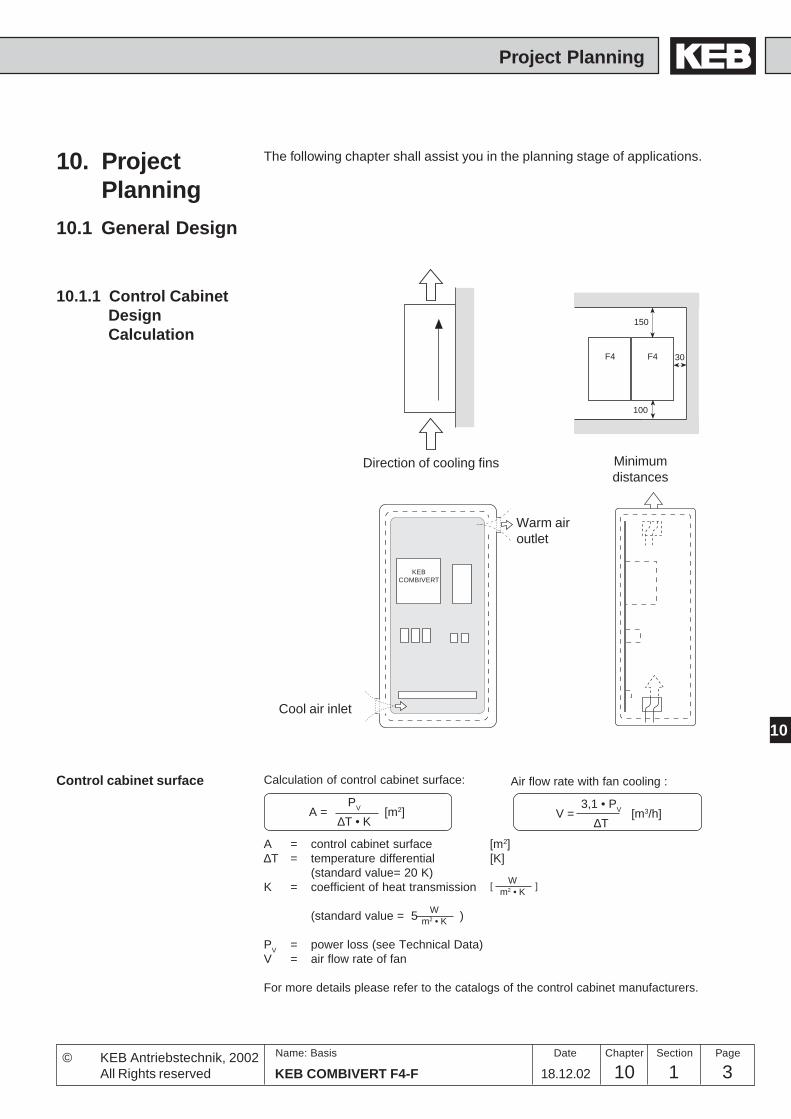
310 1 3KEB COMBIVERT F4-F
Name: Basis
10
Project Planning
Section PageDate Chapter
18.12.02© KEB Antriebstechnik, 2002
All Rights reserved
30
150
100
F4 F4
KEBCOMBIVERT
10.1 General Design
10. ProjectPlanning
The following chapter shall assist you in the planning stage of applications.
10.1.1 Control CabinetDesignCalculation
Control cabinet surface Calculation of control cabinet surface:
PVA = [m2]∆T • K
Air flow rate with fan cooling :
3,1 • PVV = [m3/h]∆T
A = control cabinet surface [m2]∆T = temperature differential [K]
(standard value= 20 K)K = coefficient of heat transmission
(standard value = 5 )
PV = power loss (see Technical Data)V = air flow rate of fan
For more details please refer to the catalogs of the control cabinet manufacturers.
W[ ]
m2 • K
Direction of cooling fins Minimumdistances
Warm airoutlet
Cool air inlet
Wm2 • K
10 1 KEB COMBIVERT F4-F4Name: Basis
Project Planning
Chapter Section Page Date
18.12.02© KEB Antriebstechnik, 2002
All Rights reserved
10.1.2 Design ofBraking Resistors
The COMBIVERT fitted with an external braking resistor or an external braking optionis suitable for a limited 4-quadrant operation. The braking energy, refed into the DC-bus atgeneratoric operation, is dissipated over the braking transistor to the braking resistor.The braking resistor heats up during the braking process. If it is installed in a controlcabinet sufficient cooling of the control cabinet interior and sufficient distance to theKEB COMBIVERT must be observed.
Different braking resistors are available for the KEB COMBIVERT. Please refer to thenext page for the corresponding formula and restrictions (valid range)
1. Preset desired braking time.
2. Calculate braking time without braking resistor (tBmin
).
3. If the desired braking time shall be smaller than the calculated time, it is necessayto use a braking resistor. (t
B < t
Bmin)
4. Calculate braking torque (MB). Take the load torque into account at the calculation.
5. Calculate peak braking power (PB). The peak braking power must always be
calculated for the worst case (nmax
to standstill).
6. Selection of braking resistor:a) P
R > P
B
b) PN is to be selected according to the cycle time (c.d.f.).
The braking resistors may be used only for the listed unit sizes. The maximumcyclic duration of a braking resistor shall not be exceeded.
6 % c.d.f. = maximum braking time 8 s25 % c.d.f.=maximum braking time 30 s40 % c.d.f. = maximum braking time 48 s
For longer cyclic duration times special designed braking resistors are necessary.The continuous output of the braking transistor must be taken into consideration.
7. Check, whether the desired braking time is attained with the braking resistor(t
Bmin).
Restriction: Under consideration of the rating of the braking resistor and thebrake power of the motor, the braking torque may not exceed 1.5times of therating torque of the motor.When utilizing the maximum possible braking torque the frequency inverter mustbe dimensioned for the higher current.
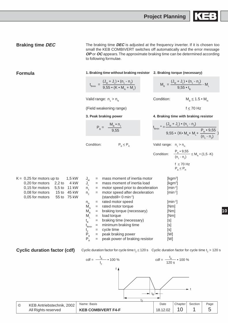
510 1 5KEB COMBIVERT F4-F
Name: Basis
10
Project Planning
Section PageDate Chapter
18.12.02© KEB Antriebstechnik, 2002
All Rights reserved
( )
(JM + J
L) • (n
1 - n
2)
tBmin
=9,55 • (K • M
N + M
L)
1. Braking time without braking resistor 2. Braking torque (necessary)
4. Braking time with braking resistor
Formula
Valid range: n1 > n
N
(Field weakening range)
Condition: MB < 1.5 • M
N
f < 70 Hz
Condition: PB < PR Valid range: n1 > nN
PR • 9,55Condition: < MN • (1,5 -K)
(n1 - n2)
f < 70 HzPB < PR
JM
= mass moment of inertia motor [kgm2]J
L= mass moment of inertia load [kgm2]
n1
= motor speed prior to deceleration [min-1]n
2= motor speed after deceleration [min-1]
(standstill= 0 min-1)n
N= rated motor speed [min-1]
MN
= rated motor torque [Nm]M
B= braking torque (necessary) [Nm]
ML
= load torque [Nm]tB
= braking time (necessary) [s]tBmin
= minimum braking time [s]tZ
= cycle time [s]P
B= peak braking power [W]
PR
= peak power of braking resistor [W]
(JM + J
L) • (n
1 - n
2)
MB = - M
L9,55 • tB
MB • n
1PB =
9,55
3. Peak braking power
(JM + J
L) • (n
1 - n
2)
tBmin
* =P
R • 9,55
9,55 • K• MN+ M
L+
(n1 - n
2)
Cyclic duration factor (cdf)tBcdf = • 100 %
120 s
Cyclic duration factor for cycle time tZ > 120 s
tBcdf = • 100 %tZ
Cyclic duration factor for cycle time tZ < 120 s
t
f
tB
tZ
Braking time DEC The braking time DEC is adjusted at the frequency inverter. If it is chosen toosmall the KEB COMBIVERT switches off automatically and the error messageOP or OC appears. The approximate braking time can be determined accordingto following formulae.
K = 0,25 for motors up to 1,5 kW0,20 for motors 2,2 to 4 kW0,15 for motors 5,5 to 11 kW0,08 for motors 15 to 45 kW0,05 for motors 55 to 75 kW

10 1 KEB COMBIVERT F4-F6Name: Basis
Project Planning
Chapter Section Page Date
18.12.02© KEB Antriebstechnik, 2002
All Rights reserved
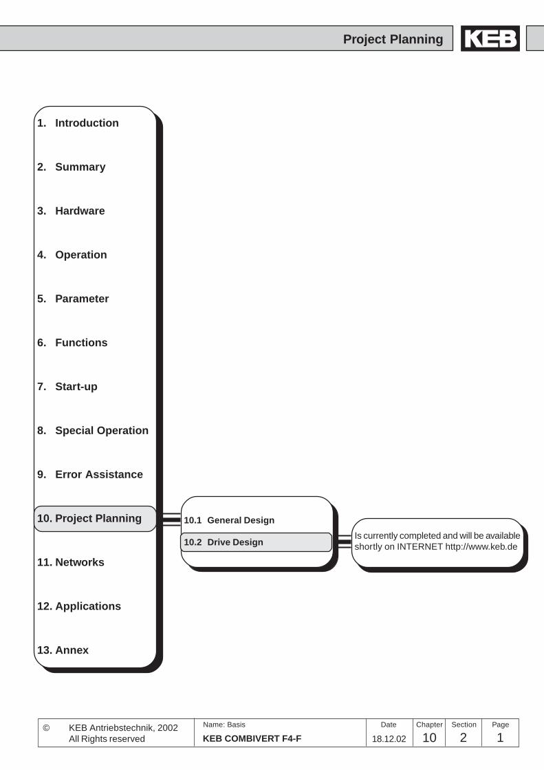
10 2 1KEB COMBIVERT F4-F
Name: Basis
Project Planning
Chapter Section PageDate
1. Introduction
2. Summary
3. Hardware
4. Operation
5. Parameter
6. Functions
7. Start-up
8. Special Operation
9. Error Assistance
10. Project Planning
11. Networks
12. Applications
13. Annex
10.1 General Design
10.2 Drive Design
18.12.02© KEB Antriebstechnik, 2002
All Rights reserved
Is currently completed and will be availableshortly on INTERNET http://www.keb.de

10 2 KEB COMBIVERT F4-F2Name: Basis
Project Planning Drive Design
Chapter Section Page Date
18.12.02© KEB Antriebstechnik, 2002
All Rights reserved

Netzwerkbetrieb
11 1 1KEB COMBIVERT F4-F
Name: Basis
1. Introduction
2. Summary
3. Hardware
4. Operation
5. Parameter
6. Functions
7. Start-up
8. Special Operation
9. Error Assistance
10. Project Planning
11. Networks
12. Applications
13. Annex
Networks
Chapter Section PageDate
11.1 Network Components
11.2 Bus-Parameter
18.12.02© KEB Antriebstechnik, 2002
All Rights reserved
11.1.1 Available Hardware ................ 311.1.2 RS232-Cable PC/Inverter ...... 311.1.3 Interface- and BUS-Operator . 411.1.4 Optical Fibre BUS .................. 511.1.5 InterBus Loop-Operator ......... 9

11 1 2Name: Basis
KEB COMBIVERT F4-F05.01.99Chapter Section © KEB Antriebstechnik, 1998
All Rights reservedPage Date
Networks Network Hardware
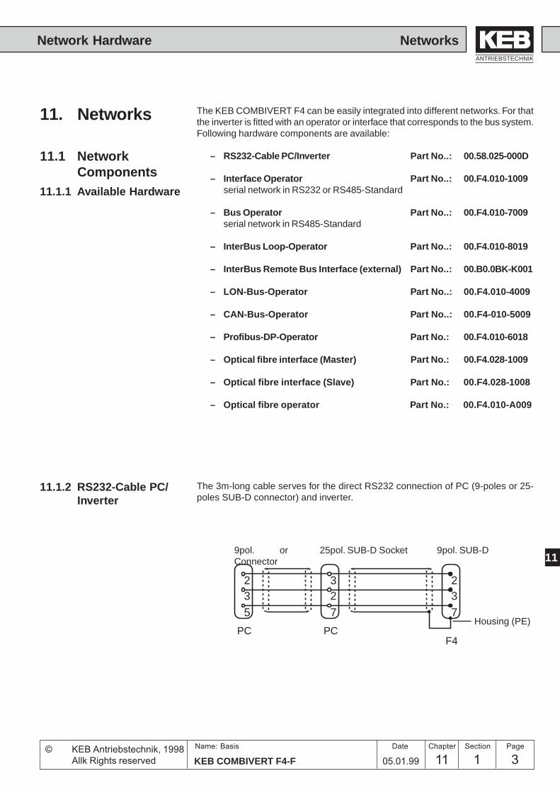
3
ANTRIEBSTECHNIK
11 1 3
11
KEB COMBIVERT F4-F
Name: Basis
05.01.99Chapter Section PageDate© KEB Antriebstechnik, 1998
Allk Rights reserved
NetworksNetwork Hardware
32
7
23
7
23
5
11.1.1 Available Hardware
11.1 NetworkComponents
The KEB COMBIVERT F4 can be easily integrated into different networks. For thatthe inverter is fitted with an operator or interface that corresponds to the bus system.Following hardware components are available:
– RS232-Cable PC/Inverter Part No..: 00.58.025-000D
– Interface Operator Part No..: 00.F4.010-1009serial network in RS232 or RS485-Standard
– Bus Operator Part No..: 00.F4.010-7009serial network in RS485-Standard
– InterBus Loop-Operator Part No..: 00.F4.010-8019
– InterBus Remote Bus Interface (external) Part No..: 00.B0.0BK-K001
– LON-Bus-Operator Part No..: 00.F4.010-4009
– CAN-Bus-Operator Part No..: 00.F4-010-5009
– Profibus-DP-Operator Part No.: 00.F4.010-6018
– Optical fibre interface (Master) Part No.: 00.F4.028-1009
– Optical fibre interface (Slave) Part No.: 00.F4.028-1008
– Optical fibre operator Part No.: 00.F4.010-A009
11. Networks
11.1.2 RS232-Cable PC/Inverter
The 3m-long cable serves for the direct RS232 connection of PC (9-poles or 25-poles SUB-D connector) and inverter.
9pol. or 25pol. SUB-D Socket 9pol. SUB-DConnector
Housing (PE)PC PC
F4
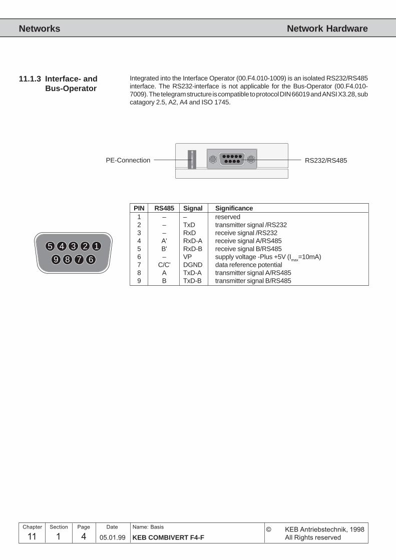
11 1 4Name: Basis
KEB COMBIVERT F4-F05.01.99Chapter Section © KEB Antriebstechnik, 1998
All Rights reservedPage Date
Networks Network Hardware
5 24 3 1
9 8 7 6
11.1.3 Interface- andBus-Operator
Integrated into the Interface Operator (00.F4.010-1009) is an isolated RS232/RS485interface. The RS232-interface is not applicable for the Bus-Operator (00.F4.010-7009). The telegram structure is compatible to protocol DIN 66019 and ANSI X3.28, subcatagory 2.5, A2, A4 and ISO 1745.
RS232/RS485PE-Connection
PIN RS485 Signal Significance1 – – reserved2 – TxD transmitter signal /RS2323 – RxD receive signal /RS2324 A' RxD-A receive signal A/RS4855 B' RxD-B receive signal B/RS4856 – VP supply voltage -Plus +5V (I
max=10mA)
7 C/C' DGND data reference potential8 A TxD-A transmitter signal A/RS4859 B TxD-B transmitter signal B/RS485
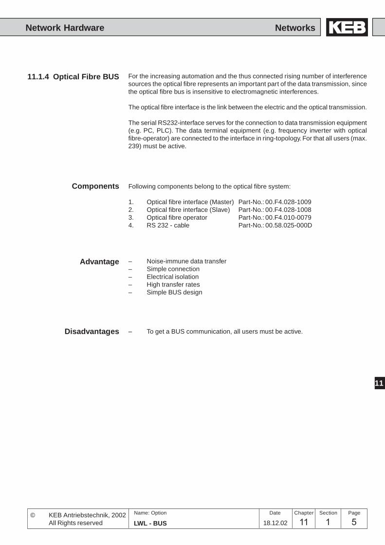
511 1 5
11
LWL - BUS
Name: Option Chapter Section PageDate
NetworksNetwork Hardware
18.12.02© KEB Antriebstechnik, 2002
All Rights reserved
11.1.4 Optical Fibre BUS
– Noise-immune data transfer– Simple connection– Electrical isolation– High transfer rates– Simple BUS design
Components
Disadvantages
Advantage
– To get a BUS communication, all users must be active.
Following components belong to the optical fibre system:
1. Optical fibre interface (Master) Part-No.: 00.F4.028-10092. Optical fibre interface (Slave) Part-No.: 00.F4.028-10083. Optical fibre operator Part-No.: 00.F4.010-00794. RS 232 - cable Part-No.: 00.58.025-000D
For the increasing automation and the thus connected rising number of interferencesources the optical fibre represents an important part of the data transmission, sincethe optical fibre bus is insensitive to electromagnetic interferences.
The optical fibre interface is the link between the electric and the optical transmission.
The serial RS232-interface serves for the connection to data transmission equipment(e.g. PC, PLC). The data terminal equipment (e.g. frequency inverter with opticalfibre-operator) are connected to the interface in ring-topology. For that all users (max.239) must be active.

11 1 6Name: Option
00.F4.Z1A-KB15
Chapter Section Page Date
Networks Network Hardware
18.12.02© KEB Antriebstechnik, 2002
All Rights reserved
Pin assignment 9-pole SUB-D connector (Slave)PIN Signal Significance1 - free2 TxD transmitter signal / RS2323 RxD receive signal / RS2324 - free5 - free6 - free7 DGND data reference potential8 - free9 - free
AB
52
43
1
98
76
BA
+ -15 ... 30 V DC
75 m
m
22,5 mm
105 mm
DescriptionOptical Fibre Operator
Switch
Receiver
TransmitterTransmitter-LED
Receiving-LED
Description Optical Fibre Interface
Transmitter-LED
Receiver
Transmitter
Switch
9-pole SUB-Dsocket
Receiving-LED
Operatingvoltage-LED
The difference between LWL-Interface Master and Slave is as follows:The Master has a 9-pole SUB-D socket and the Slave a 9-pole SUB-D connector. Itmust be taken into consideration that the PIN’s of the connector must be assigned inthe opposite of the socket in mirror position.
The housing is on all common DIN EN mounting rails mountable.
Pin assignment 9-pole SUB-D socket (Master)PIN Signal Significance1 - free2 TxD transmitter signal / RS2323 RxD receive signal / RS2324 - free5 DGND data reference potential6 - free7 - free8 - free9 - free
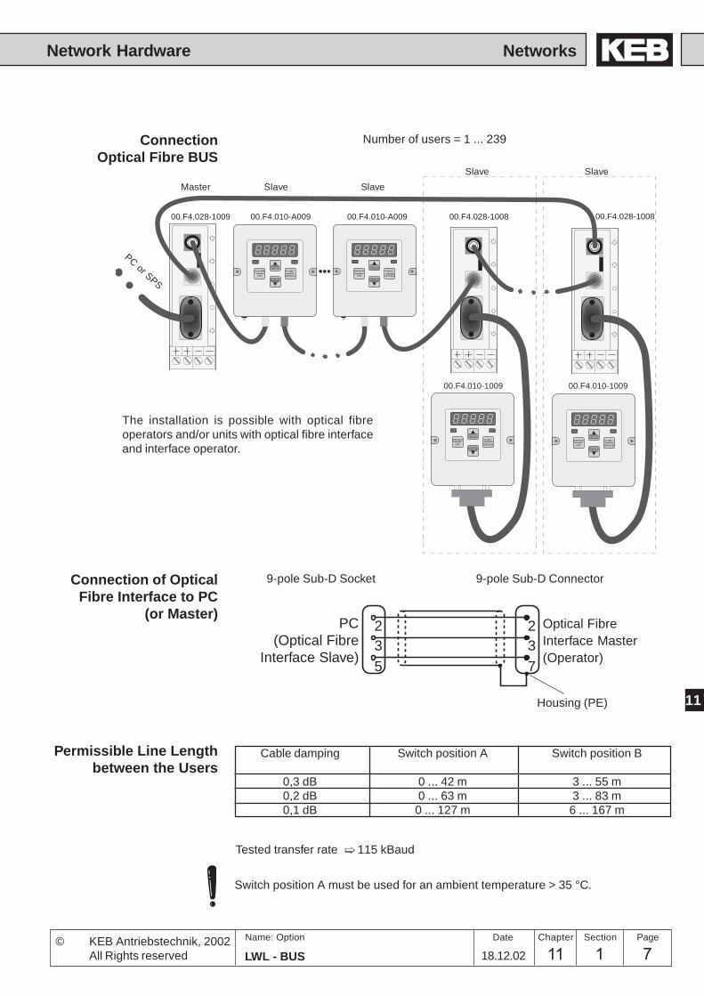
711 1 7
11
LWL - BUS
Name: Option Chapter Section PageDate
NetworksNetwork Hardware
18.12.02© KEB Antriebstechnik, 2002
All Rights reserved
START
STOP
FUNC.
SPEED
ENTER
F/R
START
STOP
FUNC.
SPEED
ENTER
F/R
START
STOP
FUNC.
SPEED
ENTER
F/R
START
STOP
FUNC.
SPEED
ENTER
F/R
23
5
23
7
00.F4.028-1009 00.F4.010-A009 00.F4.010-A009 00.F4.028-1008 00.F4.028-1008
00.F4.010-1009 00.F4.010-1009
Master Slave Slave
Slave Slave
Number of users = 1 ... 239ConnectionOptical Fibre BUS
Permissible Line Lengthbetween the Users
Cable damping Switch position A Switch position B
0,3 dB 0 ... 42 m 3 ... 55 m0,2 dB 0 ... 63 m 3 ... 83 m0,1 dB 0 ... 127 m 6 ... 167 m
Tested transfer rate 115 kBaud
PC or SPS
9-pole Sub-D Socket 9-pole Sub-D Connector
Housing (PE)
Switch position A must be used for an ambient temperature > 35 °C.
Connection of OpticalFibre Interface to PC
(or Master)Optical FibreInterface Master(Operator)
PC(Optical Fibre
Interface Slave)
The installation is possible with optical fibreoperators and/or units with optical fibre interfaceand interface operator.

11 1 8Name: Option
00.F4.Z1A-KB15
Chapter Section Page Date
Networks Network Hardware
18.12.02© KEB Antriebstechnik, 2002
All Rights reserved
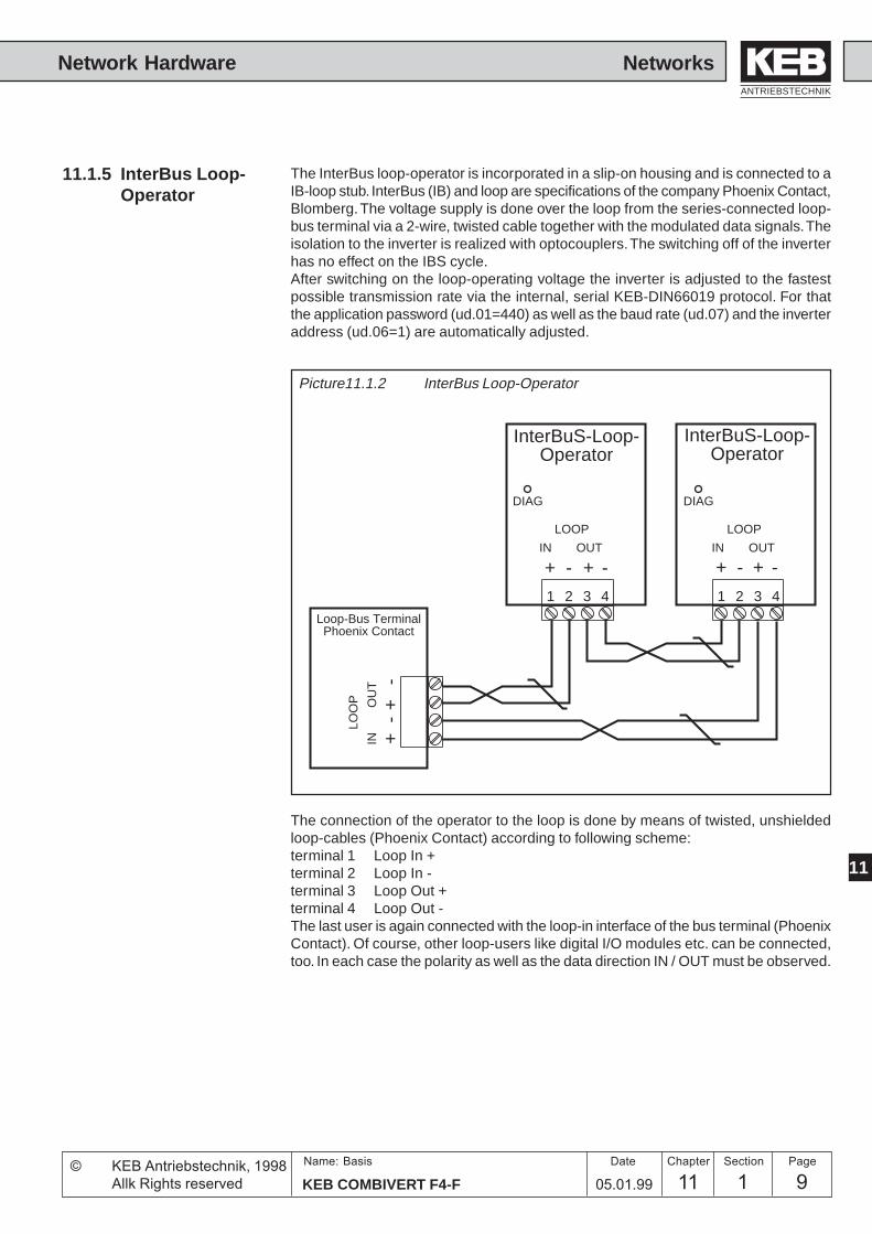
9
ANTRIEBSTECHNIK
11 1 9
11
KEB COMBIVERT F4-F
Name: Basis
05.01.99Chapter Section PageDate© KEB Antriebstechnik, 1998
Allk Rights reserved
NetworksNetwork Hardware
Loop-Bus TerminalPhoenix Contact
LOO
P
IN
OU
T
+ -
+
-
LOOP
IN OUT
LOOP
IN OUT
InterBuS-Loop-Operator
InterBuS-Loop-Operator
DIAG DIAG
1 2 3 4 1 2 3 4
+ - + - + - + -
11.1.5 InterBus Loop-Operator
The InterBus loop-operator is incorporated in a slip-on housing and is connected to aIB-loop stub. InterBus (IB) and loop are specifications of the company Phoenix Contact,Blomberg. The voltage supply is done over the loop from the series-connected loop-bus terminal via a 2-wire, twisted cable together with the modulated data signals. Theisolation to the inverter is realized with optocouplers. The switching off of the inverterhas no effect on the IBS cycle.After switching on the loop-operating voltage the inverter is adjusted to the fastestpossible transmission rate via the internal, serial KEB-DIN66019 protocol. For thatthe application password (ud.01=440) as well as the baud rate (ud.07) and the inverteraddress (ud.06=1) are automatically adjusted.
Picture11.1.2 InterBus Loop-Operator
The connection of the operator to the loop is done by means of twisted, unshieldedloop-cables (Phoenix Contact) according to following scheme:terminal 1 Loop In +terminal 2 Loop In -terminal 3 Loop Out +terminal 4 Loop Out -The last user is again connected with the loop-in interface of the bus terminal (PhoenixContact). Of course, other loop-users like digital I/O modules etc. can be connected,too. In each case the polarity as well as the data direction IN / OUT must be observed.

11 1 10Name: Basis
KEB COMBIVERT F4-F05.01.99Chapter Section © KEB Antriebstechnik, 1998
All Rights reservedPage Date
Networks Network Hardware
111 2 1KEB COMBIVERT F4-FName: Basis
Netzwerkbetrieb
06.11.02
1. Introduction
2. Summary
3. Hardware
4. Operation
5. Parameter
6. Functions
7. Start-up
8. Special Operation
9. Error Assistance
10. Project Planning
11. Networks
12. Applikations
13. Annex
11.1 Network Components
11.2 Bus-Parameter
Chapter Section PageDate© KEB Antriebstechnik, 2002All Rights reserved
Networks
11.2.1 Adjustment of InverterAddress .................................. 3
11.2.2 Baud Rate .............................. 311.2.3 Used parameter ...................... 4

11 2 2 06.11.02 KEB COMBIVERT F4-F
Name:Basis
Networks Bus-Parameter
Chapter Section © KEB Antriebstechnik, 2002All Rights reserved
Page Date
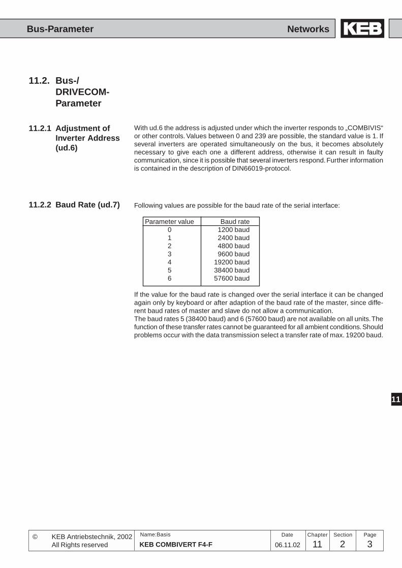
311 2 3
Bedienung
11
06.11.02KEB COMBIVERT F4-F
Name:Basis
NetworksBus-Parameter
Chapter Section PageDate© KEB Antriebstechnik, 2002All Rights reserved
11.2.1 Adjustment ofInverter Address(ud.6)
11.2.2 Baud Rate (ud.7)
With ud.6 the address is adjusted under which the inverter responds to „COMBIVIS“or other controls. Values between 0 and 239 are possible, the standard value is 1. Ifseveral inverters are operated simultaneously on the bus, it becomes absolutelynecessary to give each one a different address, otherwise it can result in faultycommunication, since it is possible that several inverters respond. Further informationis contained in the description of DIN66019-protocol.
Following values are possible for the baud rate of the serial interface:
Parameter value Baud rate0 1200 baud1 2400 baud2 4800 baud3 9600 baud4 19200 baud5 38400 baud6 57600 baud
If the value for the baud rate is changed over the serial interface it can be changedagain only by keyboard or after adaption of the baud rate of the master, since diffe-rent baud rates of master and slave do not allow a communication.The baud rates 5 (38400 baud) and 6 (57600 baud) are not available on all units. Thefunction of these transfer rates cannot be guaranteed for all ambient conditions. Shouldproblems occur with the data transmission select a transfer rate of max. 19200 baud.
11.2. Bus-/DRIVECOM-Parameter

11 2 4 06.11.02 KEB COMBIVERT F4-F
Name:Basis
Networks Bus-Parameter
Chapter Section © KEB Antriebstechnik, 2002All Rights reserved
Page Date
Param. Adr. min max default
ENTERPROG.R/W
Step
ud.6 2606h - 0 239 1 1 -
ud.7 2607h - 0 6 1 3 = 1200 to 57600 Baud
ud.8 2608h - 0 s 10,00 s 0,01s 0: off -
11.2.3 Used parameter
112 1 1KEB COMBIVERT F4-F
Name: Basis
Netzwerkbetrieb
1. Introduction
2. Summary
3. Hardware
4. Operation
5. Parameter
6. Functions
7. Start-up
8. Special Operation
9. Error Assistance
10. Project Planning
11. Networks
12. Applications
13. Annex
Here solved applications are filedwhich can be retrieved from theINTERNET http://www.keb.de.
Chapter Section PageDate
Applications
18.12.02© KEB Antriebstechnik, 2002
All Rights reserved

12 1 2 KEB COMBIVERT F4-F
Name: Basis
Applications
Chapter Section Page Date
18.12.02© KEB Antriebstechnik, 2002
All Rights reserved
12. Applications
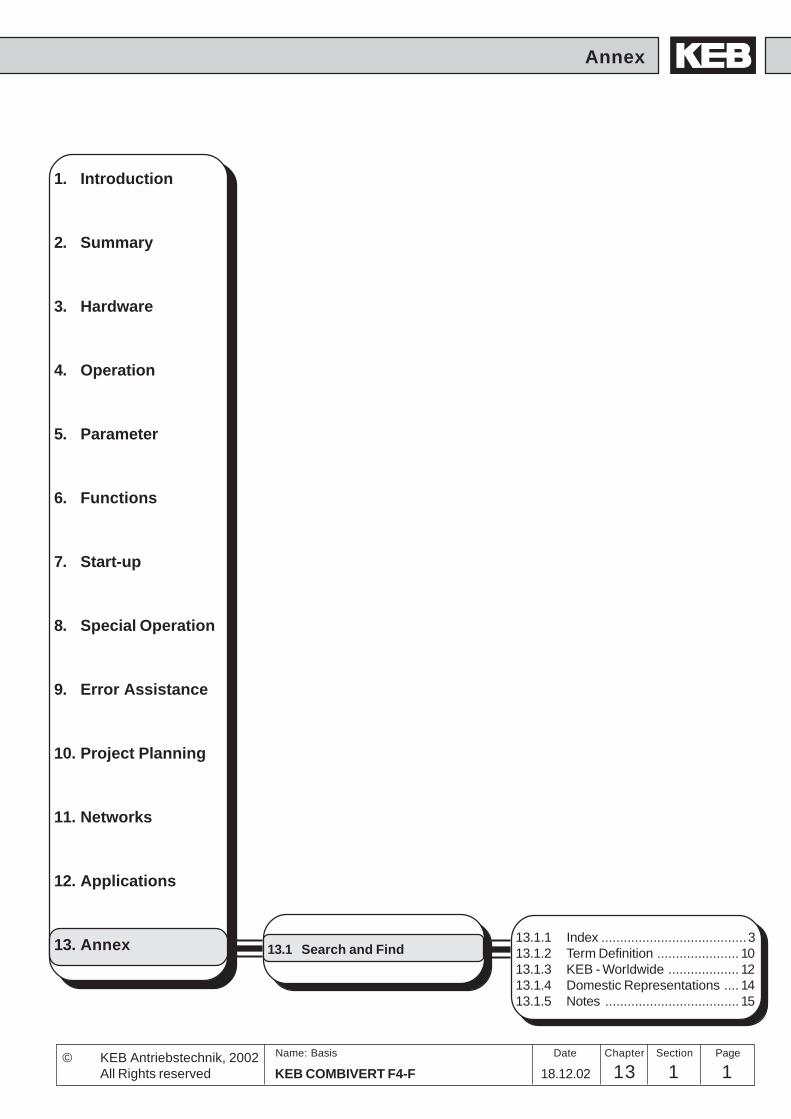
Annex
1. Introduction
2. Summary
3. Hardware
4. Operation
5. Parameter
6. Functions
7. Start-up
8. Special Operation
9. Error Assistance
10. Project Planning
11. Networks
12. Applications
13. Annex 13.1 Search and Find
13 1 1KEB COMBIVERT F4-F
Name: Basis Section PageDate Chapter
18.12.02© KEB Antriebstechnik, 2002
All Rights reserved
13.1.1 Index .......................................313.1.2 Term Definition ...................... 1013.1.3 KEB - Worldwide ................... 1213.1.4 Domestic Representations .... 1413.1.5 Notes .................................... 15

13 1 KEB COMBIVERT F4-F2Name: Basis
Annex Search and Find
Chapter Section Page Date
18.12.02© KEB Antriebstechnik, 2002
All Rights reserved

13 1 3KEB COMBIVERT F4-F
Name: Basis
13
AnnexSearch and Find
Section PageDate Chapter
18.12.02© KEB Antriebstechnik, 2002
All Rights reserved
13.1 Search and Find
13.1.1 Index
13. Annex
Symbols
230V-Class 2.1.6400V-Class 2.1.7, 2.1.8
A
AA. 0... 6 6.8.7AA. 7...13 6.8.8Abnormal Stopping 4.3.6Acceleration time 4.3.7, 6.11.10Active
current 6.1.9parameter set 6.1.12
Actualload 6.1.9position 6.1.14speed
display 4.3.5, 6.1.8master 6.1.13
torque display 4.3.7, 6.1.8Adaption factor 6.5.14Adjustment
assistant 6.8.7possibilities 4.4.3
An. 1 6.2.6An. 2 6.2.9An. 3... 5 6.2.6An. 8 6.2.9An. 9...11 6.2.6An.12 6.2.3An.13 6.4.5, 6.4.9, 6.8.9An.15 6.2.11An.16 6.2.11An.19 6.2.11An.20 6.2.11Analog
inputs 6.2.3outputs 6.2.3, 6.2.10setpoints 6.4.5
Angularcorrection 6.10.11difference
resetting 6.10.6deviation 6.1.13
Apparentcurrent 6.1.9
motor current 4.3.6Application 4.2.3
mode 4.1.3time 6.8.3
Automatic restart 6.6.5AUX-Function 4.3.22, 6.4.4,
6.4.5, 6.4.9, 6.8.9
B
Baud rate 11.2.3bbl 4.3.6Binary-coded
set selection 6.7.5Boost 4.3.4, 4.3.20, 6.5.6Brake control 6.8.3
examples 6.8.4Braking
resistors 10.1.4time DEC 10.1.5torque 10.1.4, 10.1.5
emergency stop 6.6.7Bus
error 9.1.4operator 11.1.4
C
c.d.f. 10.1.4Cable damping 11.1.7CAN-Bus 11.1.3
operator 11.1.3Change encoder
rotation 4.3.21Clock frequency
encoder 1 6.9.6encoder 2 6.9.9
Codeencoder 2 6.9.9
Config-file-number 6.1.17Control
cabinet 10.1.3card defect 9.1.5terminal strip 3.1.5units 3.1.3
Controlleractivation 6.5.5adjustment 6.5.3structure 6.5.9
Coolant
warning 6.8.13Corner speed 6.5.11CP
mode 4.3.3on 4.2.3parameter 4.3.3
assignment 6.12.4definition 6.12.3
read only 4.2.3service 4.2.3
CP. 0 4.3.5CP. 1 4.3.5CP. 2...4 4.3.6CP. 5...7 4.3.7CP. 8...9 4.3.8CP.10...11 4.3.10CP.12...14 4.3.11CP.15 4.3.12CP.16 4.3.13CP.17 4.3.14CP.18 4.3.15CP.19...21 4.3.16CP.22 4.3.17CP.23...28 4.3.18CP.29...31 4.3.19CP.30...31 4.3.19CP.32...33 4.3.20CP.34...35 4.3.21CP.36 4.3.22CPU-error 9.1.5CS-parameter 6.5.5CS. 0 6.5.10CS. 1 6.5.10CS. 3 6.5.10CS. 4 6.5.10CS. 6... 9 6.5.11CS.10 6.5.14CS.11...14 6.5.10CS.19...21 6.5.11CS.22 6.5.13CS.23 6.5.5CS.39 6.5.13CS.40 6.5.13Current Control 6.5.10, 4.3.17Customer
mode 4.1.3number 6.1.17
Cyclic duration factor (cdf) 10.1.5
D
DC-link voltage 6.1.9
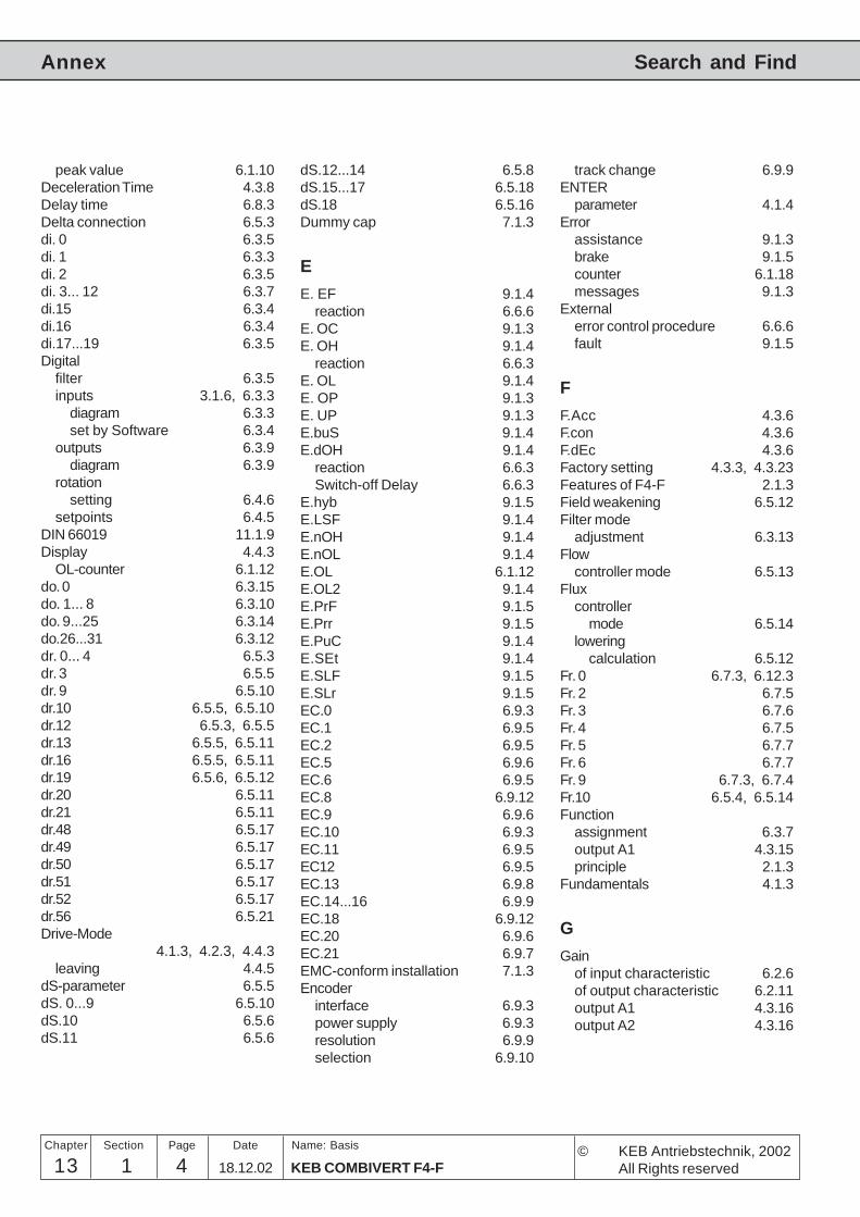
13 1 KEB COMBIVERT F4-F4Name: Basis
Annex Search and Find
Chapter Section Page Date
18.12.02© KEB Antriebstechnik, 2002
All Rights reserved
peak value 6.1.10Deceleration Time 4.3.8Delay time 6.8.3Delta connection 6.5.3di. 0 6.3.5di. 1 6.3.3di. 2 6.3.5di. 3... 12 6.3.7di.15 6.3.4di.16 6.3.4di.17...19 6.3.5Digital
filter 6.3.5inputs 3.1.6, 6.3.3
diagram 6.3.3set by Software 6.3.4
outputs 6.3.9diagram 6.3.9
rotationsetting 6.4.6
setpoints 6.4.5DIN 66019 11.1.9Display 4.4.3
OL-counter 6.1.12do. 0 6.3.15do. 1... 8 6.3.10do. 9...25 6.3.14do.26...31 6.3.12dr. 0... 4 6.5.3dr. 3 6.5.5dr. 9 6.5.10dr.10 6.5.5, 6.5.10dr.12 6.5.3, 6.5.5dr.13 6.5.5, 6.5.11dr.16 6.5.5, 6.5.11dr.19 6.5.6, 6.5.12dr.20 6.5.11dr.21 6.5.11dr.48 6.5.17dr.49 6.5.17dr.50 6.5.17dr.51 6.5.17dr.52 6.5.17dr.56 6.5.21Drive-Mode
4.1.3, 4.2.3, 4.4.3leaving 4.4.5
dS-parameter 6.5.5dS. 0...9 6.5.10dS.10 6.5.6dS.11 6.5.6
dS.12...14 6.5.8dS.15...17 6.5.18dS.18 6.5.16Dummy cap 7.1.3
E
E. EF 9.1.4reaction 6.6.6
E. OC 9.1.3E. OH 9.1.4
reaction 6.6.3E. OL 9.1.4E. OP 9.1.3E. UP 9.1.3E.buS 9.1.4E.dOH 9.1.4
reaction 6.6.3Switch-off Delay 6.6.3
E.hyb 9.1.5E.LSF 9.1.4E.nOH 9.1.4E.nOL 9.1.4E.OL 6.1.12E.OL2 9.1.4E.PrF 9.1.5E.Prr 9.1.5E.PuC 9.1.4E.SEt 9.1.4E.SLF 9.1.5E.SLr 9.1.5EC.0 6.9.3EC.1 6.9.5EC.2 6.9.5EC.5 6.9.6EC.6 6.9.5EC.8 6.9.12EC.9 6.9.6EC.10 6.9.3EC.11 6.9.5EC12 6.9.5EC.13 6.9.8EC.14...16 6.9.9EC.18 6.9.12EC.20 6.9.6EC.21 6.9.7EMC-conform installation 7.1.3Encoder
interface 6.9.3power supply 6.9.3resolution 6.9.9selection 6.9.10
track change 6.9.9ENTER
parameter 4.1.4Error
assistance 9.1.3brake 9.1.5counter 6.1.18messages 9.1.3
Externalerror control procedure 6.6.6fault 9.1.5
F
F.Acc 4.3.6F.con 4.3.6F.dEc 4.3.6Factory setting 4.3.3, 4.3.23Features of F4-F 2.1.3Field weakening 6.5.12Filter mode
adjustment 6.3.13Flow
controller mode 6.5.13Flux
controllermode 6.5.14
loweringcalculation 6.5.12
Fr. 0 6.7.3, 6.12.3Fr. 2 6.7.5Fr. 3 6.7.6Fr. 4 6.7.5Fr. 5 6.7.7Fr. 6 6.7.7Fr. 9 6.7.3, 6.7.4Fr.10 6.5.4, 6.5.14Function
assignment 6.3.7output A1 4.3.15principle 2.1.3
Fundamentals 4.1.3
G
Gainof input characteristic 6.2.6of output characteristic 6.2.11output A1 4.3.16output A2 4.3.16
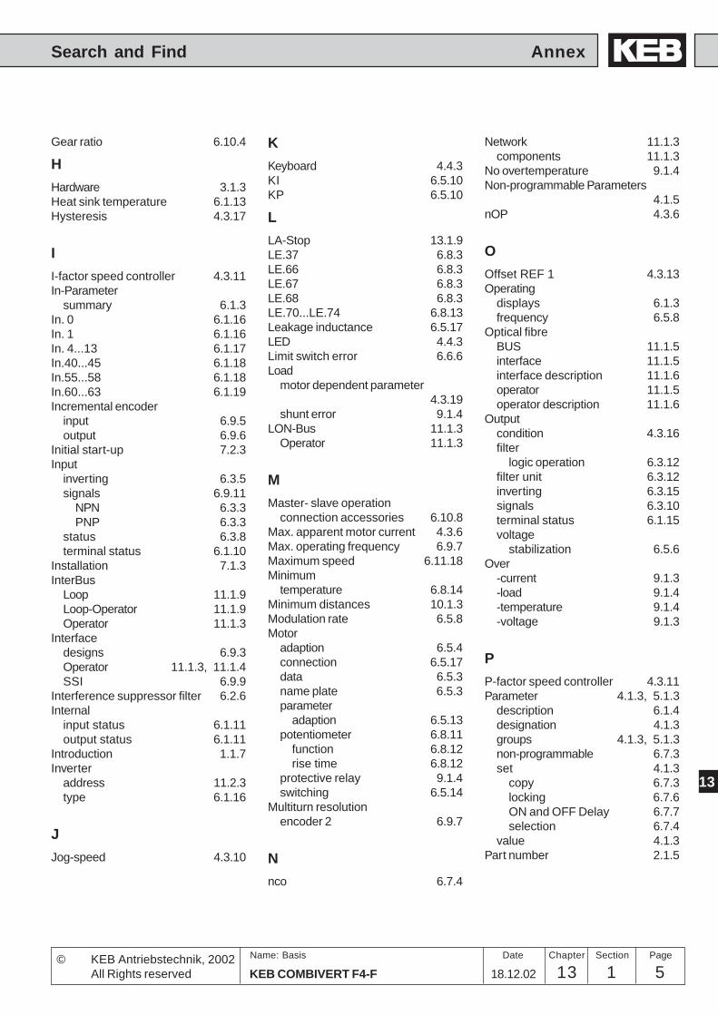
13 1 5KEB COMBIVERT F4-F
Name: Basis
13
AnnexSearch and Find
Section PageDate Chapter
18.12.02© KEB Antriebstechnik, 2002
All Rights reserved
Gear ratio 6.10.4
H
Hardware 3.1.3Heat sink temperature 6.1.13Hysteresis 4.3.17
I
I-factor speed controller 4.3.11In-Parameter
summary 6.1.3In. 0 6.1.16In. 1 6.1.16In. 4...13 6.1.17In.40...45 6.1.18In.55...58 6.1.18In.60...63 6.1.19Incremental encoder
input 6.9.5output 6.9.6
Initial start-up 7.2.3Input
inverting 6.3.5signals 6.9.11
NPN 6.3.3PNP 6.3.3
status 6.3.8terminal status 6.1.10
Installation 7.1.3InterBus
Loop 11.1.9Loop-Operator 11.1.9Operator 11.1.3
Interfacedesigns 6.9.3Operator 11.1.3, 11.1.4SSI 6.9.9
Interference suppressor filter 6.2.6Internal
input status 6.1.11output status 6.1.11
Introduction 1.1.7Inverter
address 11.2.3type 6.1.16
J
Jog-speed 4.3.10
K
Keyboard 4.4.3KI 6.5.10KP 6.5.10
L
LA-Stop 13.1.9LE.37 6.8.3LE.66 6.8.3LE.67 6.8.3LE.68 6.8.3LE.70...LE.74 6.8.13Leakage inductance 6.5.17LED 4.4.3Limit switch error 6.6.6Load
motor dependent parameter4.3.19
shunt error 9.1.4LON-Bus 11.1.3
Operator 11.1.3
M
Master- slave operationconnection accessories 6.10.8
Max. apparent motor current 4.3.6Max. operating frequency 6.9.7Maximum speed 6.11.18Minimum
temperature 6.8.14Minimum distances 10.1.3Modulation rate 6.5.8Motor
adaption 6.5.4connection 6.5.17data 6.5.3name plate 6.5.3parameter
adaption 6.5.13potentiometer 6.8.11
function 6.8.12rise time 6.8.12
protective relay 9.1.4switching 6.5.14
Multiturn resolutionencoder 2 6.9.7
N
nco 6.7.4
Network 11.1.3components 11.1.3
No overtemperature 9.1.4Non-programmable Parameters
4.1.5nOP 4.3.6
O
Offset REF 1 4.3.13Operating
displays 6.1.3frequency 6.5.8
Optical fibreBUS 11.1.5interface 11.1.5interface description 11.1.6operator 11.1.5operator description 11.1.6
Outputcondition 4.3.16filter
logic operation 6.3.12filter unit 6.3.12inverting 6.3.15signals 6.3.10terminal status 6.1.15voltage
stabilization 6.5.6Over
-current 9.1.3-load 9.1.4-temperature 9.1.4-voltage 9.1.3
P
P-factor speed controller 4.3.11Parameter 4.1.3, 5.1.3
description 6.1.4designation 4.1.3groups 4.1.3, 5.1.3non-programmable 6.7.3set 4.1.3
copy 6.7.3locking 6.7.6ON and OFF Delay 6.7.7selection 6.7.4
value 4.1.3Part number 2.1.5
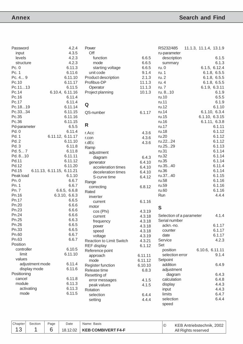
13 1 KEB COMBIVERT F4-F6Name: Basis
Annex Search and Find
Chapter Section Page Date
18.12.02© KEB Antriebstechnik, 2002
All Rights reserved
Password 4.2.4input 4.3.5levels 4.2.3structure 4.2.3
Pc. 0 6.11.3Pc. 1 6.11.6Pc. 4... 9 6.11.10Pc.10 6.11.17Pc.11...13 6.11.5Pc.14 6.10.4, 6.11.16Pc.16 6.11.4Pc.17 6.11.4Pc.18...19 6.11.14Pc.33...34 6.11.15Pc.35 6.11.16Pc.36 6.11.15Pd-parameter 6.5.5Pd. 0 6.11.4Pd. 1 6.11.12, 6.11.17Pd. 2 6.11.10Pd. 3 6.11.8Pd. 5... 7 6.11.8Pd. 8...10 6.11.11Pd.11 6.11.12Pd.12 6.11.20Pd.15 6.11.13, 6.11.15, 6.11.21Peak load 6.1.10Pn. 0 6.6.7Pn. 1 6.6.7Pn. 7 6.6.5, 6.6.8Pn.16 6.3.10, 6.6.3Pn.17 6.6.5Pn.20 6.6.6Pn.23 6.6.6Pn.24 6.6.6Pn.25 6.6.3Pn.26 6.6.5Pn.33 6.6.5Pn.60 6.6.7Pn.63 6.6.7Position
controller 6.10.5limit 6.11.10
valuesadjustment mode 6.11.4display mode 6.11.6
Positioningcancel 6.11.8module 6.11.3
activating 6.11.3mode 6.11.5
PowerOff
function 6.6.5mode 6.6.5starting voltage 6.6.5
unit code 9.1.4Product description 2.1.3Profibus-DP 11.1.3
Operator 11.1.3Project planning 10.1.3
Q
QS-number 6.1.17
R
r.Acc 4.3.6r.con 4.3.6r.dEc 4.3.6Ramp
adjustmentdiagram 6.4.3
generator 6.4.10acceleration times 6.4.10deceleration times 6.4.10S-curve time 6.4.12
Rangecorrecting 6.8.12
Ratedinverter
current 6.1.16motor
cos (Phi) 4.3.19current 4.3.18frequency 4.3.18power 4.3.18speed 4.3.18voltage 4.3.19
Reaction to Limit Switch 4.3.21REF display 6.1.12Reference point
approach 6.11.11mode 6.11.12
Register function 6.10.10Release time 6.8.3Resetting of
error messages 4.1.5peak values 4.1.5
Rotationselection 6.4.4setting 4.4.4
RS232/485 11.1.3, 11.1.4, 13.1.9ru-parameter
description 6.1.5summary 6.1.3
ru. 0 6.1.5, 6.12.4ru. 1 6.1.8, 6.5.5ru. 2 6.1.8, 6.5.5ru. 4 6.1.8, 6.5.5ru. 7 6.1.9, 6.3.11ru. 8...10 6.1.9ru.10 6.5.5ru.11 6.1.9ru.12 6.1.10ru.14 6.1.10, 6.3.4ru.15 6.1.10, 6.3.15ru.16 6.1.11, 6.3.8ru.17 6.1.11ru.18 6.1.12ru.20 6.1.12ru.22...24 6.1.12ru.25...29 6.1.13ru.31 6.1.14ru.32 6.1.14ru.35 6.1.14ru.35...40 6.11.4ru.36 6.1.14ru.37...40 6.1.15ru.58 6.1.16ru.59 6.1.16ru.60 6.1.16Run 4.4.4
S
Selection of a parameter 4.1.4Serial number
ackn.-no. 6.1.17counter 6.1.17date 6.1.17
Service 4.2.3Set
position 6.10.6, 6.11.11selection error 9.1.4
Setpointaddition 6.4.9adjustment
diagram 6.4.3calculation 6.4.8display 4.4.3input 4.4.3limits 6.4.7selection 6.4.4speed
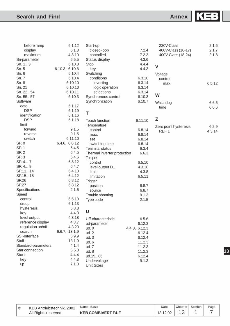
13 1 7KEB COMBIVERT F4-F
Name: Basis
13
AnnexSearch and Find
Section PageDate Chapter
18.12.02© KEB Antriebstechnik, 2002
All Rights reserved
before ramp 6.1.12display 6.1.8maximum 4.3.10
Sn-parameter 6.5.5Sn. 1...3 6.10.3Sn. 5 6.10.3, 6.10.6Sn. 6 6.10.4Sn. 7 6.10.4Sn. 8 6.10.10Sn. 21 6.10.10Sn. 22...54 6.10.11Sn. 55...57 6.10.3Software
date 6.1.17DSP 6.1.19
identification 6.1.16DSP 6.1.18
limitforward 9.1.5reverse 9.1.5switch 6.11.10
SP. 0 6.4.6, 6.8.12SP. 1 6.4.5SP. 2 6.4.5SP. 3 6.4.6SP. 4... 7 6.8.12SP. 4... 9 6.4.7SP.11...14 6.4.10SP.15...18 6.4.12SP.26 6.8.12SP.27 6.8.12Specifications 2.1.6Speed
control 6.5.10droop 6.1.13hysteresis 6.8.3key 4.4.3level output 4.3.18reference display 4.3.7regulation on/off 4.3.20search 6.6.7, 13.1.9
SSI-Interface 6.9.9Stall 13.1.9Standard-parameters 4.1.4Star connection 6.5.3Start 4.4.4
key 4.4.3up 7.1.3
Start-upclosed-loop 7.2.4controlled 7.2.3
Status display 4.3.6Stop 4.4.4
key 4.4.3Switching
conditions 6.3.10inverting 6.3.14logic operation 6.3.14selections 6.3.14
Synchronous control 6.10.3Synchronzation 6.10.7
T
Teach function 6.11.10Temperature
control 6.8.14max. 6.8.14set 6.8.14switching time 6.8.14
Terminal status 6.3.4Thermal inverter protection 6.6.3Torque
control 6.5.10level output D1 4.3.18limit 4.3.8limitation 6.5.11
Triggerposition 6.8.7source 6.8.7
Trouble shooting 9.1.3Type code 2.1.5
U
U/f-characteristic 6.5.6ud-parameter 6.12.3ud. 0 4.4.3, 6.12.3ud. 2 6.12.4ud. 3 6.12.4ud. 6 11.2.3ud. 7 11.2.3ud. 8 11.2.3ud.15...86 6.12.4Undervoltage 9.1.3Unit Sizes
230V-Class 2.1.6400V-Class (10-17) 2.1.7400V-Class (18-24) 2.1.8
V
Voltagecontrol
max. 6.5.12
W
Watchdog 6.6.6time 6.6.6
Z
Zero point hysteresis 6.2.9REF 1 4.3.14

13 1 KEB COMBIVERT F4-F8Name: Basis
Annex Search and Find
Chapter Section Page Date
18.12.02© KEB Antriebstechnik, 2002
All Rights reserved

13 1 9KEB COMBIVERT F4-F
Name: Basis
13
AnnexSearch and Find
Section PageDate Chapter
18.12.02© KEB Antriebstechnik, 2002
All Rights reserved
13.1.2 Term Definition
Analog/Digital Earth The COMBIVERT F4 has isolated digital inputs, i.e. the inputs are galvanicallyseparated from the internal potential. Thus equalizing currents between the componentsare avoided. The digital earth is the reference point of this separated control circuit. Theanalog earth is directly connected with the inverter ground, it serves as potential for theanalog setpoint setting.
EMC Electromagnetic compatibility; the guidelines for the reduction of interferences emittedby units as well as the safety of operation of troubled units.
Energy-saving Function When motors run at no-load the voltage can be lowered once this state is reachedthereby saving energy.
Frequency-dependent Switch Relay or transistor output which switches dependent of a preadjusted frequency.
Actual value At a closed-loop controlled system it is the feedback value supplied by the externaldetection. At controlled systems it is the value calculated on the basis of the adjustedconditions.
LA-Stop Acceleration stop prevents overcurrent errors during acceleration by stopping the ramp.The current level is determined through the max. ramp current (CP.14).
RS232/485 RS232, standardized serial interface for max. 1 end unit at a max. line length of 15 m.RS485, standardized serial interface for max. 240 end units and 1000 m line lengths.
Setpoint Value The analog and digital preset values with which the frequency inverter shall operate.
Speed Search Speed Search prevents overcurrent errors at the connection to rotating motors. Themotor speed is indirectly determined , the inverter accelerates only after it has adaptedits rotary speed.
Stall The Stall function protects the inverter from switch off due to overcurrent at constantoutput frequency. On exceeding the level adjusted with CP.15 the output frequency isreduced until the value is again below the adjusted value.

13 1 KEB COMBIVERT F4-F10Name: Basis
Annex Search and Find
Chapter Section Page Date
18.12.02© KEB Antriebstechnik, 2002
All Rights reserved
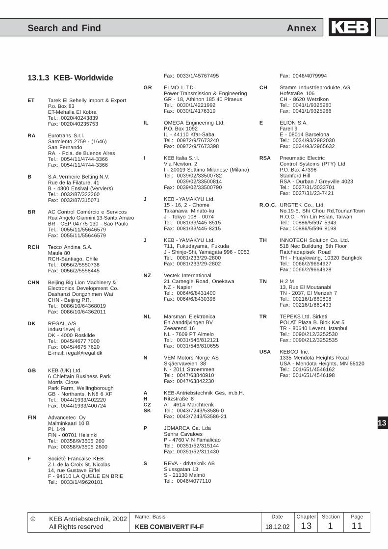
13 1 11KEB COMBIVERT F4-F
Name: Basis
13
AnnexSearch and Find
Section PageDate Chapter
18.12.02© KEB Antriebstechnik, 2002
All Rights reserved
ET Tarek El Sehelly Import & ExportP.o. Box 83ET-Mehalla El KobraTel.: 0020/40243839Fax: 0020/40235753
RA Eurotrans S.r.l.Sarmiento 2759 - (1646)San FernandoRA - Pcia. de Buenos AiresTel.: 0054/11/4744-3366Fax: 0054/11/4744-3366
B S.A. Vermeire Belting N.V.Rue de la Filature, 41B - 4800 Ensival (Verviers)Tel.: 0032/87/322360Fax: 0032/87/315071
BR AC Control Comércio e ServicosRua Angelo Giannini,13-Santa AmaroBR - CEP 04775-130 - Sao PauloTel.: 0055/11/55646579Fax: 0055/11/55646579
RCH Tecco Andina S.A.Maule 80RCH-Santiago, ChileTel.: 0056/2/5550738Fax: 0056/2/5558445
CHN Beijing Big Lion Machinery &Electronics Development Co.Dashanzi Dongzhimen WaiCHN - Beijing P.R.Tel.: 0086/10/64368019Fax: 0086/10/64362011
DK REGAL A/SIndustrievej 4DK - 4000 RoskildeTel.: 0045/4677 7000Fax: 0045/4675 7620E-mail: [email protected]
GB KEB (UK) Ltd.6 Chieftain Business ParkMorris ClosePark Farm, WellingboroughGB - Northants, NN8 6 XFTel.: 0044/1933/402220Fax: 0044/1933/400724
FIN Advancetec OyMalminkaari 10 BPL 149FIN - 00701 HelsinkiTel.: 00358/9/3505 260Fax: 00358/9/3505 2600
F Société Francaise KEBZ.I. de la Croix St. Nicolas14, rue Gustave EiffelF - 94510 LA QUEUE EN BRIETel.: 0033/1/49620101
Fax: 0033/1/45767495
GR ELMO L.T.D.Power Transmission & EngineeringGR - 18, Athinon 185 40 PiraeusTel.: 0030/1/4221992Fax: 0030/1/4176319
IL OMEGA Engineering Ltd.P.O. Box 1092IL - 44110 Kfar-SabaTel.: 00972/9/7673240Fax: 00972/9/7673398
I KEB Italia S.r.l.Via Newton, 2I - 20019 Settimo Milanese (Milano)Tel.: 0039/02/33500782
0039/02/33500814Fax: 0039/02/33500790
J KEB - YAMAKYU Ltd.15 - 16, 2 - ChomeTakanawa Minato-kuJ - Tokyo 108 - 0074Tel.: 0081/33/445-8515Fax: 0081/33/445-8215
J KEB - YAMAKYU Ltd.711, Fukudayama, FukudaJ - Shinjo-Shi, Yamagata 996 - 0053Tel.: 0081/233/29-2800Fax: 0081/233/29-2802
NZ Vectek International21 Carnegie Road, OnekawaNZ - NapierTel.: 0064/6/8431400Fax: 0064/6/8430398
NL Marsman ElektronicaEn Aandrijvingen BVZeearend 16NL - 7609 PT AlmeloTel.: 0031/546/812121Fax: 0031/546/810655
N VEM Motors Norge ASSkjäervaveien 38N - 2011 StroemmenTel.: 0047/63840910Fax: 0047/63842230
A KEB-Antriebstechnik Ges. m.b.H.H Ritzstraße 8CZ A - 4614 MarchtrenkSK Tel.: 0043/7243/53586-0
Fax: 0043/7243/53586-21
P JOMARCA Ca. LdaSenra CavaloesP - 4760 V. N FamalicaoTel.: 00351/52/315144Fax: 00351/52/311430
S REVA - drivteknik ABSlussgatan 13S - 21130 MalmöTel.: 0046/4077110
Fax: 0046/4079994
CH Stamm Industrieprodukte AGHofstraße 106CH - 8620 WetzikonTel.: 0041/1/9325980Fax: 0041/1/9325986
E ELION S.A.Farell 9E - 08014 BarcelonaTel.: 0034/93/2982030Fax: 0034/93/2965632
RSA Pneumatic ElectricControl Systems (PTY) Ltd.P.O. Box 47396Stamford HillRSA - Durban / Greyville 4023Tel.: 0027/31/3033701Fax: 0027/31/23-7421
R.O.C. URGTEK Co., Ltd.No.19-5, Shi Chou Rd,TounanTownR.O.C. - Yin-Lin Hsian, TaiwanTel.: 00886/5/597 5343Fax.: 00886/5/596 8198
TH INNOTECH Solution Co. Ltd.518 Nec Buildung, 5th FloorRatchadapisek RoadTH - Huaykwang, 10320 BangkokTel.: 0066/2/9664927Fax.: 0066/2/9664928
TN H 2 M13, Rue El MoutanabiTN - 2037, El Menzah 7Tel.: 00216/1/860808Fax: 00216/1/861433
TR TEPEKS Ltd. SirketiPOLAT Plaza B. Blok Kat 5TR - 80640 Levent, IstanbulTel.: 0090/212/3252530Fax.: 0090/212/3252535
USA KEBCO Inc.1335 Mendota Heights RoadUSA - Mendota Heights, MN 55120Tel.: 001/651/4546162Fax: 001/651/4546198
13.1.3 KEB- Worldwide
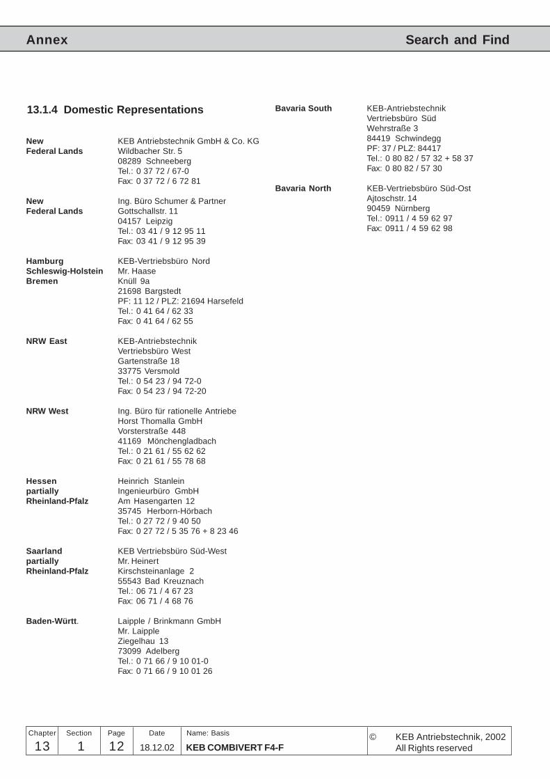
13 1 KEB COMBIVERT F4-F12Name: Basis
Annex Search and Find
Chapter Section Page Date
18.12.02© KEB Antriebstechnik, 2002
All Rights reserved
New KEB Antriebstechnik GmbH & Co. KGFederal Lands Wildbacher Str. 5
08289 SchneebergTel.: 0 37 72 / 67-0Fax: 0 37 72 / 6 72 81
New Ing. Büro Schumer & PartnerFederal Lands Gottschallstr. 11
04157 LeipzigTel.: 03 41 / 9 12 95 11Fax: 03 41 / 9 12 95 39
Hamburg KEB-Vertriebsbüro NordSchleswig-Holstein Mr. HaaseBremen Knüll 9a
21698 BargstedtPF: 11 12 / PLZ: 21694 HarsefeldTel.: 0 41 64 / 62 33Fax: 0 41 64 / 62 55
NRW East KEB-AntriebstechnikVertriebsbüro WestGartenstraße 1833775 VersmoldTel.: 0 54 23 / 94 72-0Fax: 0 54 23 / 94 72-20
NRW West Ing. Büro für rationelle AntriebeHorst Thomalla GmbHVorsterstraße 44841169 MönchengladbachTel.: 0 21 61 / 55 62 62Fax: 0 21 61 / 55 78 68
Hessen Heinrich Stanleinpartially Ingenieurbüro GmbHRheinland-Pfalz Am Hasengarten 12
35745 Herborn-HörbachTel.: 0 27 72 / 9 40 50Fax: 0 27 72 / 5 35 76 + 8 23 46
Saarland KEB Vertriebsbüro Süd-Westpartially Mr. HeinertRheinland-Pfalz Kirschsteinanlage 2
55543 Bad KreuznachTel.: 06 71 / 4 67 23Fax: 06 71 / 4 68 76
Baden-Württ. Laipple / Brinkmann GmbHMr. LaippleZiegelhau 1373099 AdelbergTel.: 0 71 66 / 9 10 01-0Fax: 0 71 66 / 9 10 01 26
Bavaria South KEB-AntriebstechnikVertriebsbüro SüdWehrstraße 384419 SchwindeggPF: 37 / PLZ: 84417Tel.: 0 80 82 / 57 32 + 58 37Fax: 0 80 82 / 57 30
Bavaria North KEB-Vertriebsbüro Süd-OstAjtoschstr. 1490459 NürnbergTel.: 0911 / 4 59 62 97Fax: 0911 / 4 59 62 98
13.1.4 Domestic Representations

13 1 13KEB COMBIVERT F4-F
Name: Basis
13
AnnexSearch and Find
Section PageDate Chapter
18.12.02© KEB Antriebstechnik, 2002
All Rights reserved
13.1.5 Notes

13 1 KEB COMBIVERT F4-F14Name: Basis
Annex Search and Find
Chapter Section Page Date
18.12.02© KEB Antriebstechnik, 2002
All Rights reserved

13 1 15KEB COMBIVERT F4-F
Name: Basis
13
AnnexSearch and Find
Section PageDate Chapter
18.12.02© KEB Antriebstechnik, 2002
All Rights reserved

©K
EB
00.F
4.F
EA
-K13
011
/200
2
ANTRIEBSTECHNIK
Karl E. Brinkmann GmbHFörsterweg 36 - 38 • D - 32683 BarntrupTelefon 0 52 63 / 4 01 - 0 • Telefax 4 01 - 116Internet: www.keb.de • E-mail: [email protected]