Embed Size (px)
Citation preview
– 1 –
IntroductionThe antenna is probably the most overlooked part of an RF design. The range, performance, and legality of an RF link are critically dependent upon the antenna. However, it is often left until the end of the design andexpected to fit into whatever space is left, no matter how unfavorable to performance that location may be. Many of these designs will have to ultimately accept degraded performance or go through multiple redesigns.
The antenna is one of the most complicated aspects of RF design. With so many interdependent variables, application becomes as much art as science. Engineers delving into RF design for the first time can quite easily confuse or misinterpret the meaning of antenna specifications and how to apply them. For instance, the gain of an antenna is very different from the gain of an amplifier. The most common misconception may be that the radiation pattern on a monopole antenna’s data sheet will be that of the antenna on the final product. In actuality, the radiation pattern for a quarter-wave monopole antenna is so critically dependent on the design and layout of the product that manufacturers’ gain specifications and radiation pattern plots have little use except to ascertain potential antenna performance.
Since voluminous texts have been written about each of the many an-tenna styles, it is unnecessary to cover them all here. This article will focus only on those styles which are commonly used in low-power handheldproducts: dipole and monopole whips. These styles cover a wide range of available antennas and are among the most common to be implemented incorrectly. With that in mind, there are several rules of thumb that canbe applied to antenna designs. These rules are less “how to design an antenna” and more “how to design with an antenna.”
Antenna FundamentalsAn antenna is a device that converts electric currents into electromagnetic waves and vice versa. It can be considered a complex RLC network. At some frequencies, it will appear as an inductive reactance and at others as a capacitive reactance. At a specific frequency, both of the reactances will be equal in magnitude but opposite in influence and thus cancel each other. At this specific frequency, the impedance is purely resistive and the antenna is said to be resonant.
Here is where the physical meets the theoretical. Resonance will occur at whole number multiples or fractions of the frequency of interest. These frequencies correspond to a wavelength. That wavelength is the required
Understanding Antenna Specifications and Operation
Application Note AN-00501
Revised 8/20/12
– 2 – Application Note AN-00501
antenna length. That length is what must be incorporated into the final product, either embedded inside the enclosure or externally attached to the device. The frequency of the electromagnetic waves is related to the wavelength by the following equation:
wheref = frequency in hertz (Hz) = wavelength in meters (m)c = speed of light (299,792,458 m/s)
As can be seen by the equation, the higher the frequency, the shorter the wavelength and the smaller the antenna. For example, the wavelength for 433.92MHz is 0.69m (2.27ft) and the wavelength for 916MHz is 0.33m (1.07ft). 433.92MHz is a popular frequency for remote keyless entry (RKE) systems such as car keyfobs, but obviously there is no way that a 2.27-foot antenna is going to fit into a keyfob.
Fortunately for everyone who wants to carry their keys in their pocket, there are ways to make the antenna smaller. Since resonance will occur at whole number fractions (½, 1⁄3, ¼, etc.) of the fundamental frequency,shorter antennas can be used to send and recover the signal. As with everything in engineering, there is a tradeoff. Reducing the antenna’s size will have some impact on the efficiency and impedance of the antenna, which can affect the final performance of the system.
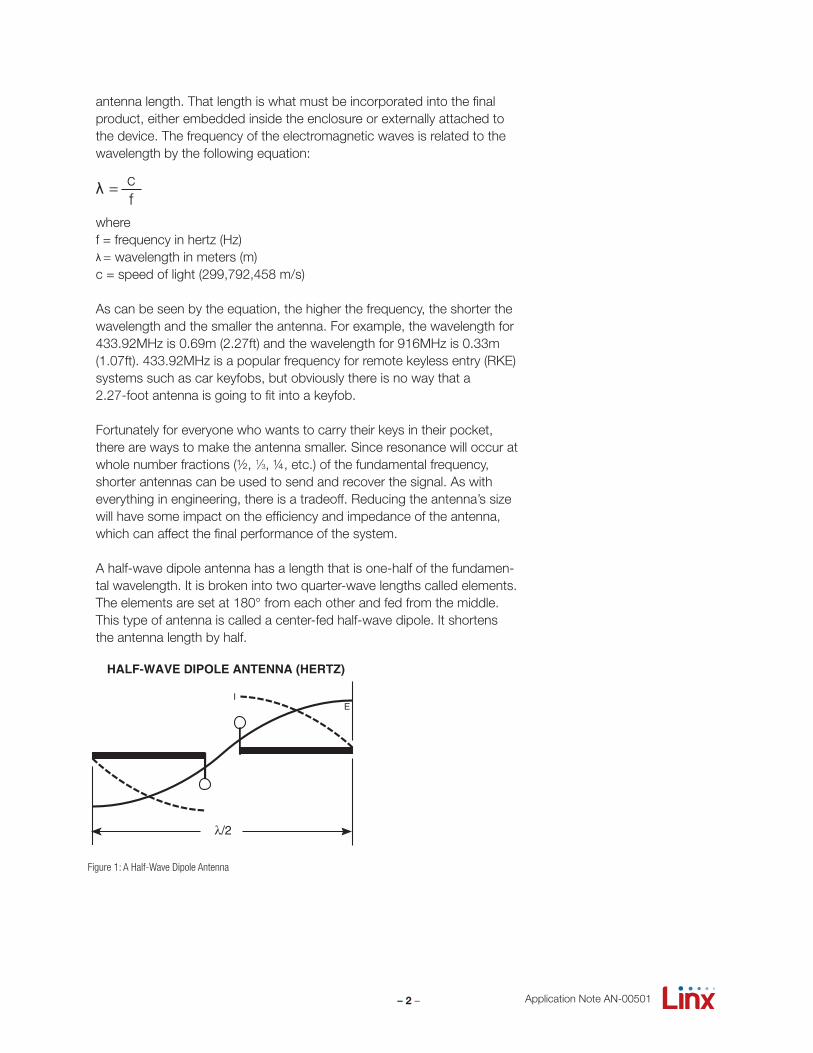
A half-wave dipole antenna has a length that is one-half of the fundamen-tal wavelength. It is broken into two quarter-wave lengths called elements. The elements are set at 180° from each other and fed from the middle.This type of antenna is called a center-fed half-wave dipole. It shortens the antenna length by half.
λ = λ cf
λ
Figure 1: A Half-Wave Dipole Antenna
IE
λ/2
HALF-WAVE DIPOLE ANTENNA (HERTZ)
– 3 – Application Note AN-00501
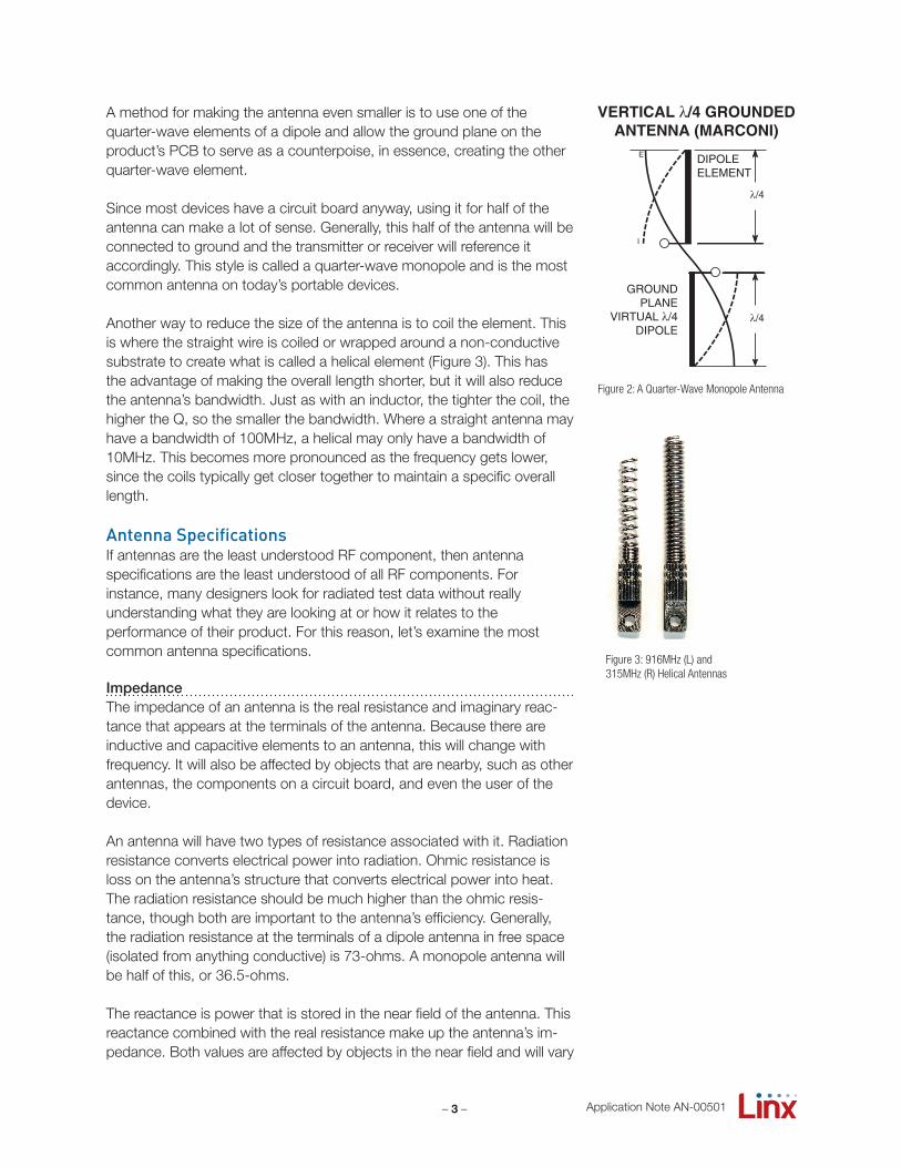
A method for making the antenna even smaller is to use one of the quarter-wave elements of a dipole and allow the ground plane on the product’s PCB to serve as a counterpoise, in essence, creating the other quarter-wave element.
Since most devices have a circuit board anyway, using it for half of the antenna can make a lot of sense. Generally, this half of the antenna will be connected to ground and the transmitter or receiver will reference itaccordingly. This style is called a quarter-wave monopole and is the most common antenna on today’s portable devices.
Another way to reduce the size of the antenna is to coil the element. This is where the straight wire is coiled or wrapped around a non-conductive substrate to create what is called a helical element (Figure 3). This has the advantage of making the overall length shorter, but it will also reduce the antenna’s bandwidth. Just as with an inductor, the tighter the coil, the higher the Q, so the smaller the bandwidth. Where a straight antenna may have a bandwidth of 100MHz, a helical may only have a bandwidth of10MHz. This becomes more pronounced as the frequency gets lower, since the coils typically get closer together to maintain a specific overall length.
Antenna SpecificationsIf antennas are the least understood RF component, then antenna specifications are the least understood of all RF components. For instance, many designers look for radiated test data without really understanding what they are looking at or how it relates to the performance of their product. For this reason, let’s examine the most common antenna specifications.
ImpedanceThe impedance of an antenna is the real resistance and imaginary reac-tance that appears at the terminals of the antenna. Because there are inductive and capacitive elements to an antenna, this will change withfrequency. It will also be affected by objects that are nearby, such as other antennas, the components on a circuit board, and even the user of the device.
An antenna will have two types of resistance associated with it. Radiation resistance converts electrical power into radiation. Ohmic resistance is loss on the antenna’s structure that converts electrical power into heat. The radiation resistance should be much higher than the ohmic resis-tance, though both are important to the antenna’s efficiency. Generally, the radiation resistance at the terminals of a dipole antenna in free space(isolated from anything conductive) is 73-ohms. A monopole antenna will be half of this, or 36.5-ohms.
The reactance is power that is stored in the near field of the antenna. This reactance combined with the real resistance make up the antenna’s im-pedance. Both values are affected by objects in the near field and will vary
I
E DIPOLEELEMENT
Figure 2: A Quarter-Wave Monopole Antenna
Figure 3: 916MHz (L) and 315MHz (R) Helical Antennas
– 4 – Application Note AN-00501
down the antenna’s length. The specifics of this are beyond the scope of this document, but can be found in most antenna literature.
These values are important because, in any system, maximum power transfer will occur when the source and load impedances match. If they are different, called a mismatch, then some of the power sent to the antenna will be reflected back into the load or lost as heat. This will lower the efficiency of the system, lowering range, increasing power requirements, and shortening battery life.
Industry convention for RF is an impedance of 50-ohms. Most IC manufacturers will have matched their products to 50-ohms or will provide a circuit designed to match their product to a 50-ohm load. Likewise, antenna manufacturers frequently design and characterize antennas at 50-ohms.
VSWRThe Voltage Standing Wave Ratio (VSWR) is a measurement of how well an antenna is matched to a source impedance, typically 50-ohms. It is calculated by measuring the voltage wave that is headed toward the load versus the voltage wave that is reflected back from the load. A perfect match will have a VSWR of 1:1. The higher the first number, the worse the match and the more inefficient the system. Since a perfect match cannot ever be obtained, some benchmark for performance needs to be set. In the case of antenna VSWR, this is usually 2:1. At this point, 88.9% of the energy sent to the antenna by the transmitter is radiated into free space and 11.1% is either reflected back into the source or lost as heat on the structure of the antenna. In the other direction, 88.9% of the energy recovered by the antenna is transferred into the receiver. As a side note, since the “:1” is always implied, many data sheets will remove it and just display the first number.
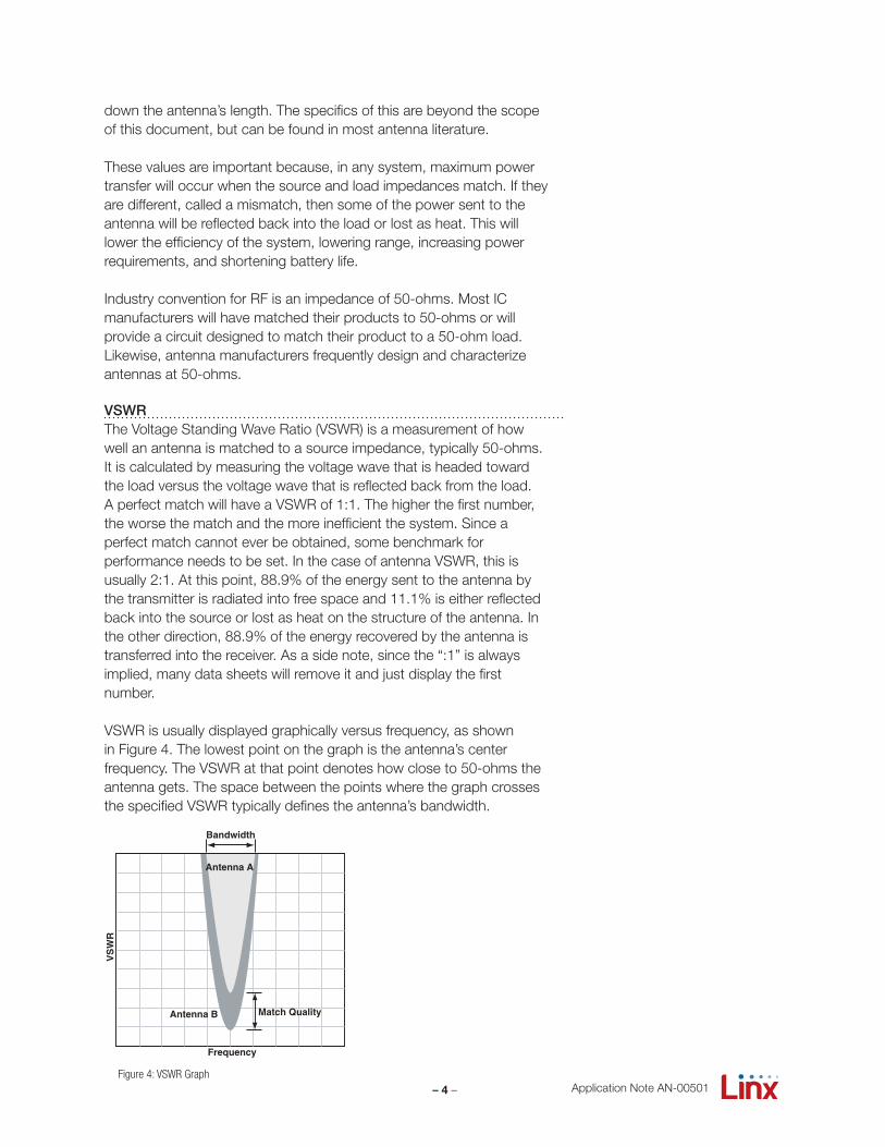
VSWR is usually displayed graphically versus frequency, as shown in Figure 4. The lowest point on the graph is the antenna’s center frequency. The VSWR at that point denotes how close to 50-ohms the antenna gets. The space between the points where the graph crosses the specified VSWR typically defines the antenna’s bandwidth.
Match QualityAntenna B
Bandwidth
Antenna A
VS
WR
Frequency
Figure 4: VSWR Graph
– 5 – Application Note AN-00501
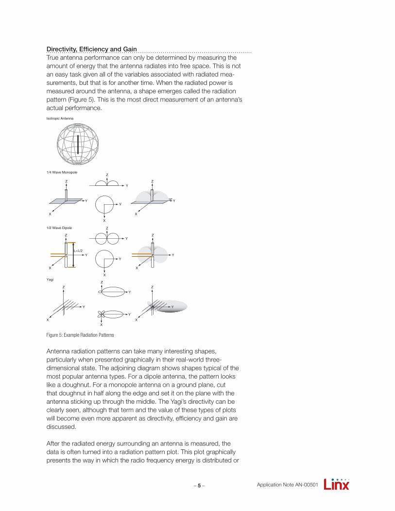
Directivity, Efficiency and GainTrue antenna performance can only be determined by measuring the amount of energy that the antenna radiates into free space. This is not an easy task given all of the variables associated with radiated mea-surements, but that is for another time. When the radiated power is measured around the antenna, a shape emerges called the radiation pattern (Figure 5). This is the most direct measurement of an antenna’s actual performance.
Antenna radiation patterns can take many interesting shapes, particularly when presented graphically in their real-world three- dimensional state. The adjoining diagram shows shapes typical of the most popular antenna types. For a dipole antenna, the pattern looks like a doughnut. For a monopole antenna on a ground plane, cut that doughnut in half along the edge and set it on the plane with the antenna sticking up through the middle. The Yagi’s directivity can be clearly seen, although that term and the value of these types of plots will become even more apparent as directivity, efficiency and gain are discussed.
After the radiated energy surrounding an antenna is measured, the data is often turned into a radiation pattern plot. This plot graphically presents the way in which the radio frequency energy is distributed or
1/4 Wave Monopole
Y
Z
X
Y
Z
X
YY
Z
X
1/2 Wave Dipole
L=λ/2Y
Z
X
X
Y
Y
Z
Y
Z
X
Y
Z
X
Y
Z
Y
X
Y
Z
X
Yagi
Isotropic Antenna
Figure 5: Example Radiation Patterns
– 6 –
-40.0
-30.0
-20.0
-10.0
0.0
10.00
270
180
9090°
270°
180°
0°
Antenna
-40.0
-30.0
-20.0
-10.0
0.0
10.00
270
180
9090°
270°
180°
0°
Antenna
ANT-916-CW-QW on Jig 51
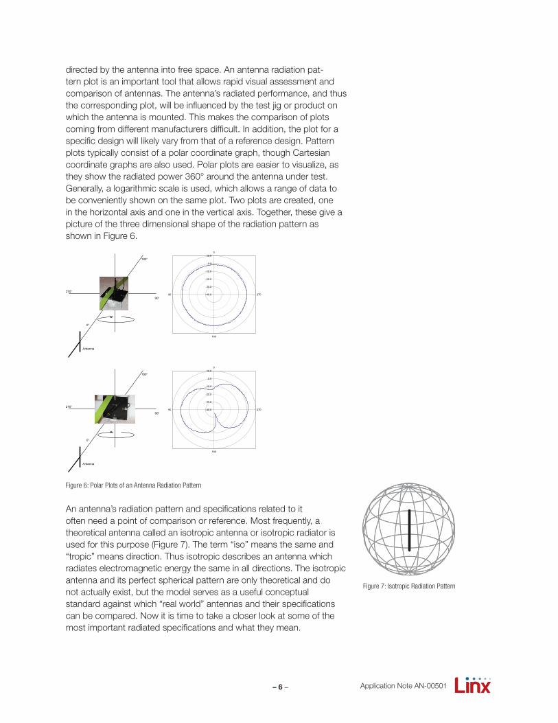
directed by the antenna into free space. An antenna radiation pat-tern plot is an important tool that allows rapid visual assessment and comparison of antennas. The antenna’s radiated performance, and thus the corresponding plot, will be influenced by the test jig or product on which the antenna is mounted. This makes the comparison of plots coming from different manufacturers difficult. In addition, the plot for aspecific design will likely vary from that of a reference design. Pattern plots typically consist of a polar coordinate graph, though Cartesian coordinate graphs are also used. Polar plots are easier to visualize, as they show the radiated power 360° around the antenna under test. Generally, a logarithmic scale is used, which allows a range of data to be conveniently shown on the same plot. Two plots are created, one in the horizontal axis and one in the vertical axis. Together, these give a picture of the three dimensional shape of the radiation pattern asshown in Figure 6.
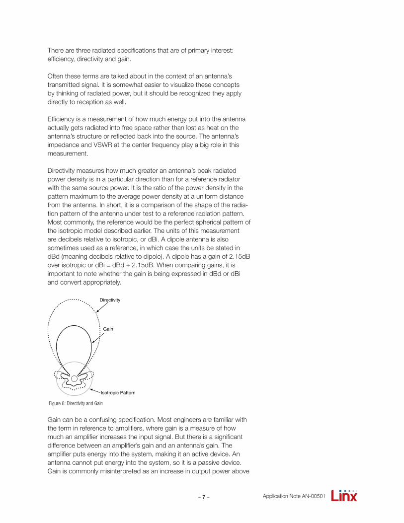
An antenna’s radiation pattern and specifications related to it often need a point of comparison or reference. Most frequently, a theoretical antenna called an isotropic antenna or isotropic radiator is used for this purpose (Figure 7). The term “iso” means the same and “tropic” means direction. Thus isotropic describes an antenna which radiates electromagnetic energy the same in all directions. The isotropic antenna and its perfect spherical pattern are only theoretical and do not actually exist, but the model serves as a useful conceptual standard against which “real world” antennas and their specifications can be compared. Now it is time to take a closer look at some of the most important radiated specifications and what they mean.
Application Note AN-00501
Figure 6: Polar Plots of an Antenna Radiation Pattern
Figure 7: Isotropic Radiation Pattern
– 7 – Application Note AN-00501
There are three radiated specifications that are of primary interest:efficiency, directivity and gain.
Often these terms are talked about in the context of an antenna’s transmitted signal. It is somewhat easier to visualize these concepts by thinking of radiated power, but it should be recognized they apply directly to reception as well.
Efficiency is a measurement of how much energy put into the antennaactually gets radiated into free space rather than lost as heat on theantenna’s structure or reflected back into the source. The antenna’simpedance and VSWR at the center frequency play a big role in thismeasurement.
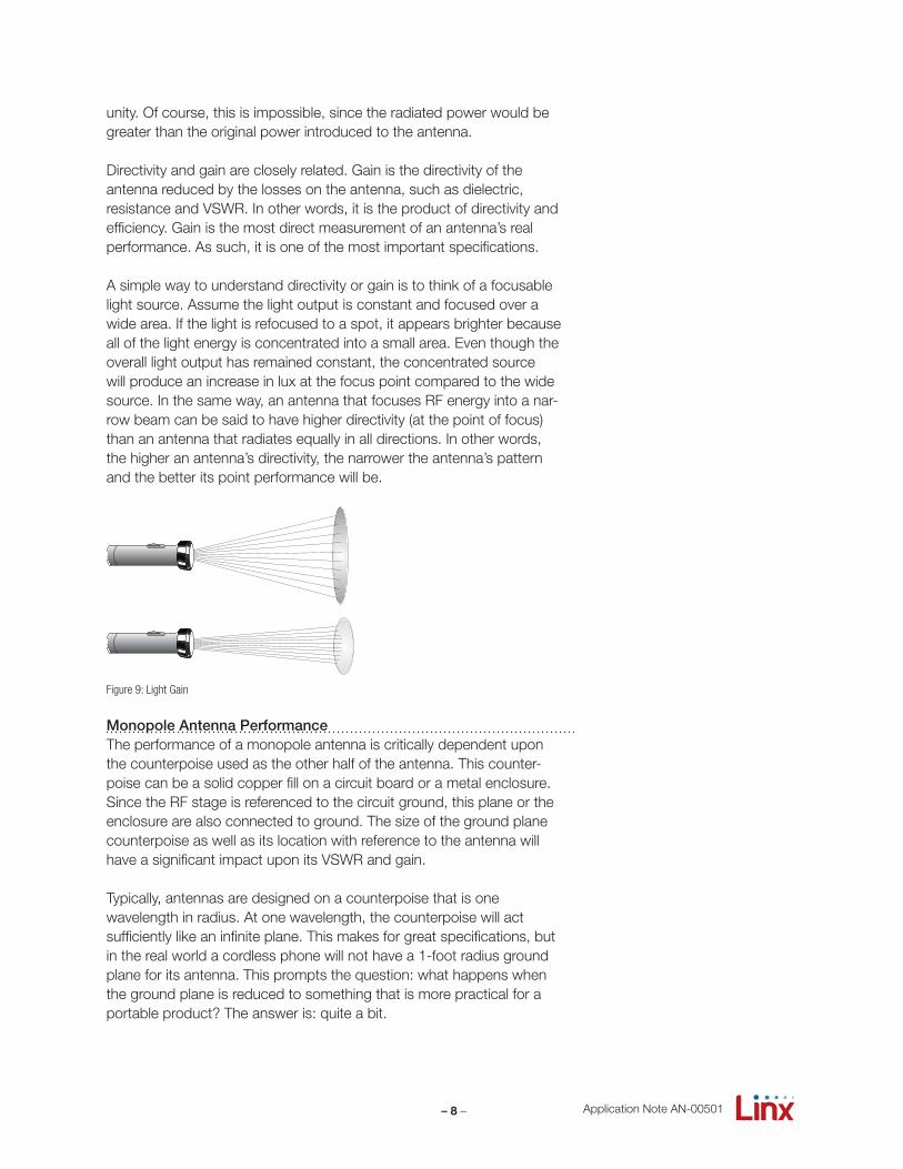
Directivity measures how much greater an antenna’s peak radiated power density is in a particular direction than for a reference radiator with the same source power. It is the ratio of the power density in the pattern maximum to the average power density at a uniform distance from the antenna. In short, it is a comparison of the shape of the radia-tion pattern of the antenna under test to a reference radiation pattern. Most commonly, the reference would be the perfect spherical pattern of the isotropic model described earlier. The units of this measurementare decibels relative to isotropic, or dBi. A dipole antenna is also sometimes used as a reference, in which case the units be stated in dBd (meaning decibels relative to dipole). A dipole has a gain of 2.15dB over isotropic or dBi = dBd + 2.15dB. When comparing gains, it is important to note whether the gain is being expressed in dBd or dBi and convert appropriately.
Gain can be a confusing specification. Most engineers are familiar with the term in reference to amplifiers, where gain is a measure of how much an amplifier increases the input signal. But there is a significant difference between an amplifier’s gain and an antenna’s gain. The amplifier puts energy into the system, making it an active device. An antenna cannot put energy into the system, so it is a passive device. Gain is commonly misinterpreted as an increase in output power above
Isotropic Pattern
Directivity
Gain
Figure 8: Directivity and Gain
– 8 – Application Note AN-00501
unity. Of course, this is impossible, since the radiated power would be greater than the original power introduced to the antenna.
Directivity and gain are closely related. Gain is the directivity of the antenna reduced by the losses on the antenna, such as dielectric, resistance and VSWR. In other words, it is the product of directivity and efficiency. Gain is the most direct measurement of an antenna’s real performance. As such, it is one of the most important specifications.
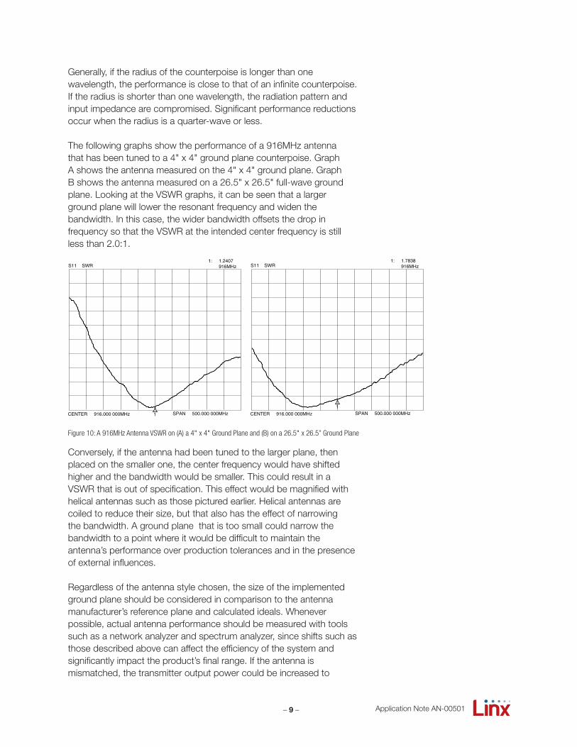
A simple way to understand directivity or gain is to think of a focusable light source. Assume the light output is constant and focused over a wide area. If the light is refocused to a spot, it appears brighter because all of the light energy is concentrated into a small area. Even though the overall light output has remained constant, the concentrated source will produce an increase in lux at the focus point compared to the wide source. In the same way, an antenna that focuses RF energy into a nar-row beam can be said to have higher directivity (at the point of focus) than an antenna that radiates equally in all directions. In other words, the higher an antenna’s directivity, the narrower the antenna’s pattern and the better its point performance will be.
Monopole Antenna PerformanceThe performance of a monopole antenna is critically dependent upon the counterpoise used as the other half of the antenna. This counter-poise can be a solid copper fill on a circuit board or a metal enclosure. Since the RF stage is referenced to the circuit ground, this plane or the enclosure are also connected to ground. The size of the ground plane counterpoise as well as its location with reference to the antenna will have a significant impact upon its VSWR and gain.
Typically, antennas are designed on a counterpoise that is one wavelength in radius. At one wavelength, the counterpoise will act sufficiently like an infinite plane. This makes for great specifications, but in the real world a cordless phone will not have a 1-foot radius ground plane for its antenna. This prompts the question: what happens when the ground plane is reduced to something that is more practical for a portable product? The answer is: quite a bit.
Figure 9: Light Gain
– 9 – Application Note AN-00501
Generally, if the radius of the counterpoise is longer than one wavelength, the performance is close to that of an infinite counterpoise. If the radius is shorter than one wavelength, the radiation pattern and input impedance are compromised. Significant performance reductions occur when the radius is a quarter-wave or less.
The following graphs show the performance of a 916MHz antenna that has been tuned to a 4" x 4" ground plane counterpoise. Graph A shows the antenna measured on the 4" x 4" ground plane. Graph B shows the antenna measured on a 26.5" x 26.5" full-wave ground plane. Looking at the VSWR graphs, it can be seen that a largerground plane will lower the resonant frequency and widen the bandwidth. In this case, the wider bandwidth offsets the drop in frequency so that the VSWR at the intended center frequency is still less than 2.0:1.
Conversely, if the antenna had been tuned to the larger plane, then placed on the smaller one, the center frequency would have shifted higher and the bandwidth would be smaller. This could result in a VSWR that is out of specification. This effect would be magnified with helical antennas such as those pictured earlier. Helical antennas are coiled to reduce their size, but that also has the effect of narrowing the bandwidth. A ground plane that is too small could narrow the bandwidth to a point where it would be difficult to maintain the antenna’s performance over production tolerances and in the presence of external influences.
Regardless of the antenna style chosen, the size of the implemented ground plane should be considered in comparison to the antenna manufacturer’s reference plane and calculated ideals. Whenever possible, actual antenna performance should be measured with tools such as a network analyzer and spectrum analyzer, since shifts such as those described above can affect the efficiency of the system and significantly impact the product’s final range. If the antenna is mismatched, the transmitter output power could be increased to
CENTER 916.000 000MHz SPAN 500.000 000MHz
S11 SWR
1
1: 1.2407 916MHz
BW = 143.89MHz
CENTER 916.000 000MHz SPAN 500.000 000MHz
S11 SWR
1
1: 1.7838 916MHz
BW = 180.94MHz
Figure 10: A 916MHz Antenna VSWR on (A) a 4" x 4" Ground Plane and (B) on a 26.5" x 26.5” Ground Plane
– 10 –
compensate, but at the cost of higher current consumption and shorter battery life. For most receivers, there is little that can be done to recover the lost sensitivity. In some cases, a low noise amplifier (LNA) can be placed after the antenna and before the receiver’s front end, but that adds to the cost, current consumption and size.
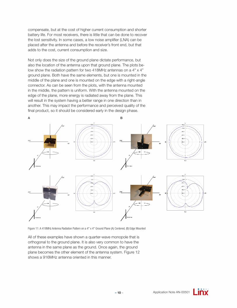
Not only does the size of the ground plane dictate performance, but also the location of the antenna upon that ground plane. The plots be-low show the radiation pattern for two 418MHz antennas on a 4" x 4” ground plane. Both have the same elements, but one is mounted in the middle of the plane and one is mounted on the edge with a right-angle connector. As can be seen from the plots, with the antenna mounted in the middle, the pattern is uniform. With the antenna mounted on the edge of the plane, more energy is radiated away from the plane. This will result in the system having a better range in one direction than in another. This may impact the performance and perceived quality of the final product, so it should be considered early in the design phase.
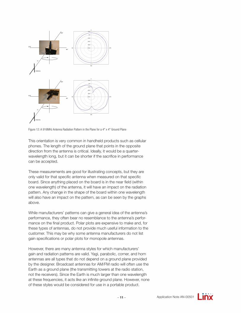
All of these examples have shown a quarter-wave monopole that is orthogonal to the ground plane. It is also very common to have the antenna in the same plane as the ground. Once again, the ground plane becomes the other element of the antenna system. Figure 12 shows a 916MHz antenna oriented in this manner.
-40.0
-30.0
-20.0
-10.0
0.0
10.00
270
180
9090°
270°
180°
0°
Antenna
-40.0
-30.0
-20.0
-10.0
0.0
10.00
270
180
9090°
270°
180°
0°
Antenna
ANT-418-CW-RH on Jig 51
A B
Figure 11: A 418MHz Antenna Radiation Pattern on a 4" x 4" Ground Plane (A) Centered, (B) Edge Mounted
Application Note AN-00501
– 11 – Application Note AN-00501
This orientation is very common in handheld products such as cellular phones. The length of the ground plane that points in the opposite direction from the antenna is critical. Ideally, it would be a quarter-wavelength long, but it can be shorter if the sacrifice in performance can be accepted.
These measurements are good for illustrating concepts, but they are only valid for that specific antenna when measured on that specific board. Since anything placed on the board is in the near field (within one wavelength) of the antenna, it will have an impact on the radiation pattern. Any change in the shape of the board within one wavelength will also have an impact on the pattern, as can be seen by the graphs above.
While manufacturers’ patterns can give a general idea of the antenna’s performance, they often bear no resemblance to the antenna’s perfor-mance on the final product. Polar plots are expensive to make and, forthese types of antennas, do not provide much useful information to the customer. This may be why some antenna manufacturers do not list gain specifications or polar plots for monopole antennas.
However, there are many antenna styles for which manufacturers’ gain and radiation patterns are valid. Yagi, parabolic, corner, and horn antennas are all types that do not depend on a ground plane provided by the designer. Broadcast antennas for AM/FM radio will often use the Earth as a ground plane (the transmitting towers at the radio station, not the receivers). Since the Earth is much larger than one wavelength at these frequencies, it acts like an infinite ground plane. However, none of these styles would be considered for use in a portable product.
ANT-916-PMA on Jig 51
-40.0
-30.0
-20.0
-10.0
0.0
10.00
270
180
90
90°
270°
180°
0°
Antenna
-40.0
-30.0
-20.0
-10.0
0.0
10.00
270
180
90
90°
270°
180°
0°
Antenna
Figure 12: A 916MHz Antenna Radiation Pattern in the Plane for a 4" x 4" Ground Plane
– 12 – Application Note AN-00501
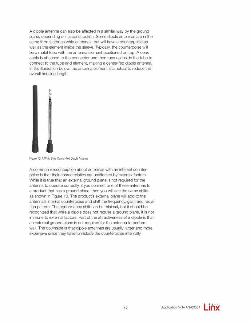
A dipole antenna can also be affected in a similar way by the ground plane, depending on its construction. Some dipole antennas are in the same form factor as whip antennas, but will have a counterpoise as well as the element inside the sleeve. Typically, the counterpoise will be a metal tube with the antenna element positioned on top. A coax cable is attached to the connector and then runs up inside the tube to connect to the tube and element, making a center-fed dipole antenna. In the illustration below, the antenna element is a helical to reduce the overall housing length.
A common misconception about antennas with an internal counter-poise is that their characteristics are unaffected by external factors. While it is true that an external ground plane is not required for the antenna to operate correctly, if you connect one of these antennas to a product that has a ground plane, then you will see the same shifts as shown in Figure 10. The product’s external plane will add to the antenna’s internal counterpoise and shift the frequency, gain, and radia-tion pattern. The performance shift can be minimal, but it should be recognized that while a dipole does not require a ground plane, it is not immune to external factors. Part of the attractiveness of a dipole is that an external ground plane is not required for the antenna to performwell. The downside is that dipole antennas are usually larger and more expensive since they have to include the counterpoise internally.
Figure 13: A Whip Style Center-Fed Dipole Antenna
– 13 –
Designing with a Quarter-Wave Monopole AntennaA common pitfall for designers new to the wireless arena is the implementation of the ground plane. As stated earlier, the ground plane is the other half of the antenna, so it is critical to the final performance of the product. This means that it is critical to get it right.
The ground plane is a solid copper fill on one layer of the circuit board that is connected to the negative terminal of the battery. This fill not only acts as the antenna’s counterpoise, but is also the ground connection for all of the components on the board. The problems arise when com-ponents are added and the traces routed to connect them.
It is a very rare and simple design that does not need to route a trace on more than one layer. Every trace that gets routed on the same layer as the ground plane can have a significant impact on the RF perfor-mance. It is best to look at the board from the perspective of the anten-na connection. The goal is to have a low impedance path back to the battery or power connection. This is accomplished with wide, unob-structed paths. If the ground plane is cut up with traces, through-hole components, or vias, then it is not going to be able to do its job as an antenna counterpoise. One of the worst things that can happen is for the ground plane to get so cut up that it has to get connected by jump-ing back and forth between layers through vias. A via has inductance associated with it, which increases its impedance at high frequency. This will result in the ground plane floating somewhere above ground at RF frequencies, which will reduce the performance of the antenna and, consequently, the range of the product.
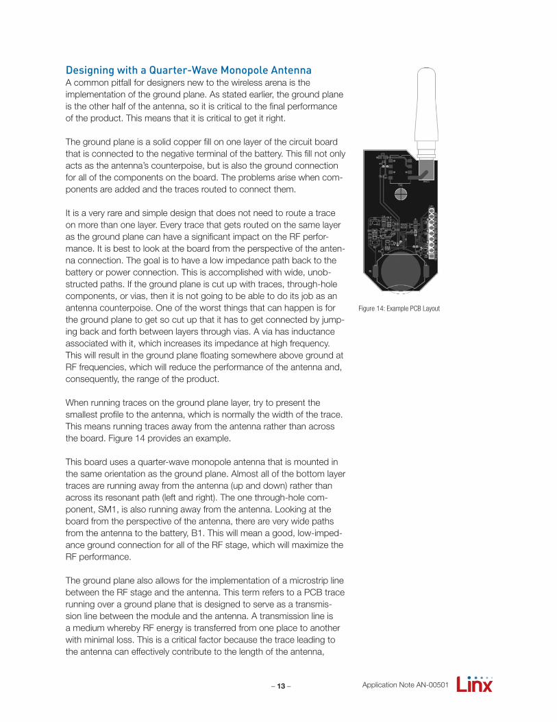
When running traces on the ground plane layer, try to present the smallest profile to the antenna, which is normally the width of the trace. This means running traces away from the antenna rather than across the board. Figure 14 provides an example.
This board uses a quarter-wave monopole antenna that is mounted in the same orientation as the ground plane. Almost all of the bottom layer traces are running away from the antenna (up and down) rather than across its resonant path (left and right). The one through-hole com-ponent, SM1, is also running away from the antenna. Looking at the board from the perspective of the antenna, there are very wide paths from the antenna to the battery, B1. This will mean a good, low-imped-ance ground connection for all of the RF stage, which will maximize the RF performance.
The ground plane also allows for the implementation of a microstrip line between the RF stage and the antenna. This term refers to a PCB trace running over a ground plane that is designed to serve as a transmis-sion line between the module and the antenna. A transmission line is a medium whereby RF energy is transferred from one place to another with minimal loss. This is a critical factor because the trace leading to the antenna can effectively contribute to the length of the antenna,
Figure 14: Example PCB Layout
Application Note AN-00501
– 14 –
changing its resonant frequency. The width of the microstrip line is based on the desired characteristic impedance of the line, the thick-ness of the PCB, and the dielectric constant of the board material. When implemented correctly, the microstrip line will connect the anten-na to the RF stage without affecting the antenna’s resonant frequency or the match to the RF stage.
One other thing that frequently seems to catch designers off guard is that standard connectors, such as SMA, BNC or MCX, are illegal for use as an antenna connection in the United States for devices falling under some sections of CFR Part 15. The FCC does not want the end user to be able to change the antenna from the one that was certified with the product. For this reason, the antenna will need to use a non-standard, proprietary, or permanent connection. Fortunately, the FCC considers reverse-polarity connectors to be non-standard, so theyare commonly used by OEMs for the antenna.
Putting it All TogetherThe antenna is a critical factor in a system’s performance and should be considered early in the design process. It should be recognized that specifications on an antenna’s data sheet will not necessarily reflect its performance in the final product. This is a result of design-specific factors such as those discussed here as well as differing references, methods of test, and presentation formats among antenna suppliers. With this in mind, allowance must be made for testing and optimizing the antenna as an integral part of the overall design process. While it is unlikely an end user will spend much time contemplating the nuances of antenna implementation, they will certainly appreciate the range and reliability of a well-designed product. The field of antenna design and application is complex, but by understanding a few ground rules, it is not necessary to be an antenna designer to design with an antenna.
Copyright © 2012 Linx Technologies
159 Ort Lane, Merlin, OR, US 97532Phone: +1 541 471 6256Fax: +1 541 471 6251www.linxtechnologies.com
Application Note AN-00501