Embed Size (px)
Citation preview
.
Avaya Solution & Interoperability Test Lab
Application Notes for DuVoice DV2000 with Avaya Communication Manager Using Analog Mode Code Integration – Issue 1.0
Abstract
These Application Notes describe the configuration procedures required for the DuVoice DV2000 to successfully interoperate with Avaya Communication Manager. The DuVoice DV2000 is a messaging system whose feature set is particularly suited for hospitality applications and includes voicemail, automated attendant, wake-up call, and a Property Management System (PMS) interface. The PMS interface is provided for connection to a third party Property Management System to provide guest check-in and checkout. A Property Management System was not included in the compliance test. The compliance testing focused on exercising the voicemail, automated attendant, and wake-up call features of the DV2000. Guest check-in and checkout was done using the Room Status Monitor feature internal to the DV2000. Basic serviceability and performance testing was also conducted to assess the reliability of the solution. Information in these notes has been obtained through compliance testing and additional technical discussions. Testing was conducted via the DeveloperConnection Program at the Avaya Solution and Interoperability Test Lab.
CTM; Reviewed: SPOC 1/23/2006
Solution & Interoperability Test Lab Application Notes ©2006 Avaya Inc. All Rights Reserved.
1 of 41 DV2000-ACM-Ana
CTM; Reviewed: SPOC 1/23/2006
Solution & Interoperability Test Lab Application Notes ©2006 Avaya Inc. All Rights Reserved.
2 of 41 DV2000-ACM-Ana
1. Introduction These Application Notes describe a compliance-tested messaging solution comprised of Avaya Communication Manager and the DuVoice DV2000 using analog mode code integration. The DV2000 feature set is particularly suited for hospitality applications and includes voicemail, automated attendant, wake-up call, and a Property Management System (PMS) interface. The PMS interface is provided for connection to a third party Property Management System to provide guest check-in and checkout. A Property Management System was not included in the compliance test. Guest check-in and checkout was done using the Room Status Monitor feature internal to the DV2000. The DuVoice DV2000 system is comprised of both hardware and software running on Microsoft Windows XP. Internally, it utilizes Intel Dialogic voice boards to support 4 - 48 analog voice ports that provide the means of connection to Avaya Communication Manager. Each analog port on the DuVoice DV2000 is connected to an analog station port controlled by Avaya Communication Manager and configured as type VMI (voice mail interface). Each time a call is routed to an extension associated with a port connected to the DuVoice DV2000, Avaya Communication Manager sends a series of DTMF tones to the DV2000 port before the call path is connected between the calling party and the DV2000. These tones, known as mode codes, provide information about the call to the DV2000 including the call type. The DV2000 uses this information to process the call. The way the different types of calls are handled by the DV2000 and the greetings and menus presented to the caller are highly configurable. For the compliance test, all the extensions associated with the ports connected to the DuVoice DV2000 were placed in a hunt group. This hunt group number was used as the general access number for the DV2000. Avaya Communication Manager and the DV2000 were configured to provide the following behavior. All incoming external calls were routed to the DV2000 access number. The DV2000 answered these calls with the automated attendant greeting and menu. All internal calls to the DV2000 access number were answered with an internal voicemail greeting that allowed users to retrieve voicemail or to schedule a wake-up call. All calls that were not answered by the intended destination were covered to the DV2000. The DV2000 answered these calls with a personal greeting recorded by the user and allowed the caller to leave a voicemail message. Upon successful recording of the message, the DV2000 used the Leave Word Calling (LWC) Send A Message feature access code to turn on the Message Waiting Indicator (MWI) of the intended destination. When the recipient retrieved the message, the DV2000 used the LWC Cancel A Message feature access code to turn off the MWI. If the user scheduled a wake-up call, the DV2000 placed a call to the originating station at the appointed time. If the user answered, a wake-up call greeting was played. If the user did not answer, the call was retried for a configurable number of times before giving up.
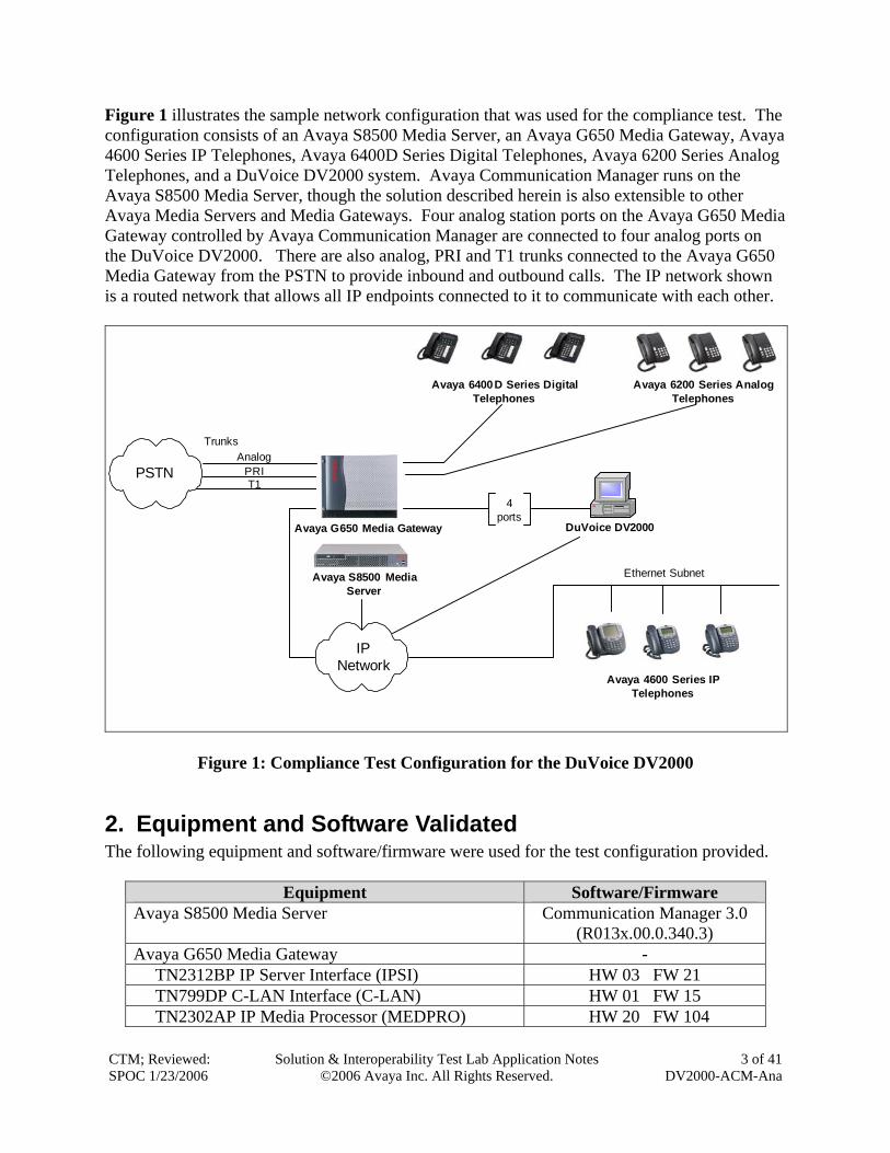
Figure 1 illustrates the sample network configuration that was used for the compliance test. The configuration consists of an Avaya S8500 Media Server, an Avaya G650 Media Gateway, Avaya 4600 Series IP Telephones, Avaya 6400D Series Digital Telephones, Avaya 6200 Series Analog Telephones, and a DuVoice DV2000 system. Avaya Communication Manager runs on the Avaya S8500 Media Server, though the solution described herein is also extensible to other Avaya Media Servers and Media Gateways. Four analog station ports on the Avaya G650 Media Gateway controlled by Avaya Communication Manager are connected to four analog ports on the DuVoice DV2000. There are also analog, PRI and T1 trunks connected to the Avaya G650 Media Gateway from the PSTN to provide inbound and outbound calls. The IP network shown is a routed network that allows all IP endpoints connected to it to communicate with each other.
Avaya S8500 Media Server
Avaya G650 Media Gateway DuVoice DV2000
Avaya 4600 Series IP Telephones
Avaya 6400D Series Digital Telephones
4ports
Avaya 6200 Series Analog Telephones
Ethernet Subnet
PSTNAnalog
T1
IP Network
PRI
Trunks
Figure 1: Compliance Test Configuration for the DuVoice DV2000
2. Equipment and Software Validated The following equipment and software/firmware were used for the test configuration provided.
Equipment Software/Firmware Avaya S8500 Media Server Communication Manager 3.0
(R013x.00.0.340.3) Avaya G650 Media Gateway - TN2312BP IP Server Interface (IPSI) HW 03 FW 21 TN799DP C-LAN Interface (C-LAN) HW 01 FW 15 TN2302AP IP Media Processor (MEDPRO) HW 20 FW 104
CTM; Reviewed: SPOC 1/23/2006
Solution & Interoperability Test Lab Application Notes ©2006 Avaya Inc. All Rights Reserved.
3 of 41 DV2000-ACM-Ana
CTM; Reviewed: SPOC 1/23/2006
Solution & Interoperability Test Lab Application Notes ©2006 Avaya Inc. All Rights Reserved.
4 of 41 DV2000-ACM-Ana
Equipment Software/Firmware TN746B Analog Line - Avaya 4600 Series IP Telephones 2.2 (4610SW H.323)
2.2 (4620SW H.323) 2.5 (4625SW H.323)
Avaya 6400D Series Digital Telephones - Avaya 6200 Series Analog Telephones - DuVoice DV2000 3.04
3. Configure Avaya Communication Manager This section describes the procedure for configuring mode code operation and VMI stations on Avaya Communication Manager. These steps are performed through the System Access Terminal (SAT). Step Description
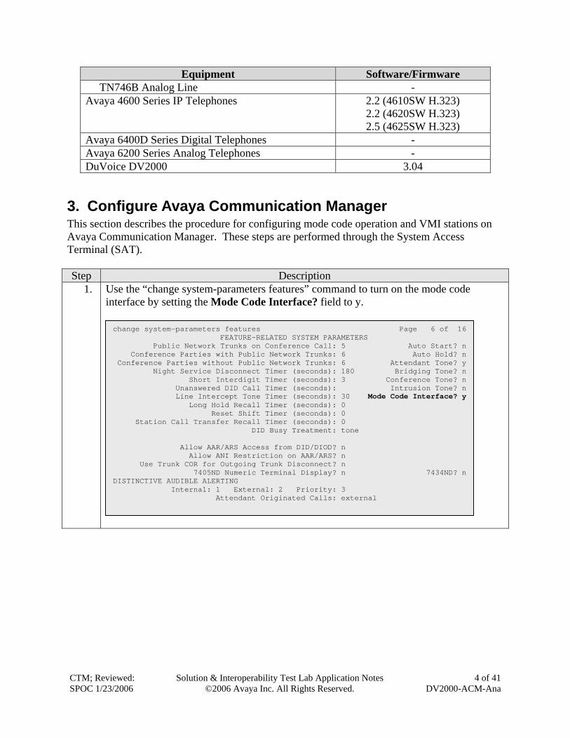
1. Use the “change system-parameters features” command to turn on the mode code interface by setting the Mode Code Interface? field to y.
change system-parameters features Page 6 of 16 FEATURE-RELATED SYSTEM PARAMETERS Public Network Trunks on Conference Call: 5 Auto Start? n Conference Parties with Public Network Trunks: 6 Auto Hold? n Conference Parties without Public Network Trunks: 6 Attendant Tone? y Night Service Disconnect Timer (seconds): 180 Bridging Tone? n Short Interdigit Timer (seconds): 3 Conference Tone? n Unanswered DID Call Timer (seconds): Intrusion Tone? n Line Intercept Tone Timer (seconds): 30 Mode Code Interface? y Long Hold Recall Timer (seconds): 0 Reset Shift Timer (seconds): 0 Station Call Transfer Recall Timer (seconds): 0 DID Busy Treatment: tone Allow AAR/ARS Access from DID/DIOD? n Allow ANI Restriction on AAR/ARS? n Use Trunk COR for Outgoing Trunk Disconnect? n 7405ND Numeric Terminal Display? n 7434ND? nDISTINCTIVE AUDIBLE ALERTING Internal: 1 External: 2 Priority: 3 Attendant Originated Calls: external
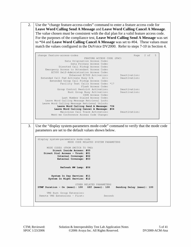
2. Use the “change feature-access-codes” command to enter a feature access code for Leave Word Calling Send A Message and Leave Word Calling Cancel A Message. The value chosen must be consistent with the dial plan for a valid feature access code. For the purposes of the compliance test, Leave Word Calling Send A Message was set to *04 and Leave Word Calling Cancel A Message was set to #04. These values must match the values configured in the DuVoice DV2000. Refer to steps 7-10 in Section 4.
3. U
p
CTM; RevSPOC 1/2
change feature-access-codes Page 2 of 5 FEATURE ACCESS CODE (FAC) Data Origination Access Code: Data Privacy Access Code: Directed Call Pickup Access Code: Emergency Access to Attendant Access Code: EC500 Self-Administration Access Code: Enhanced EC500 Activation: Deactivation: Extended Call Fwd Activate Busy D/A All: Deactivation: Extended Group Call Pickup Access Code: Facility Test Calls Access Code: *17 Flash Access Code: Group Control Restrict Activation: Deactivation: Hunt Group Busy Activation: Deactivation: ISDN Access Code: Last Number Dialed Access Code: Leave Word Calling Message Retrieval Lock: Leave Word Calling Message Retrieval Unlock: Leave Word Calling Send A Message: *04 Leave Word Calling Cancel A Message: #04 Malicious Call Trace Activation: Deactivation: Meet-me Conference Access Code Change:
se the “display system-parameters mode-code” command to verify that the mode code arameters are set to the default values shown below.
display system-parameters mode-code MODE CODE RELATED SYSTEM PARAMETERS MODE CODES (FROM SWITCH TO VMS) Direct Inside Access: #00 Direct Dial Access - Trunk: #01 Internal Coverage: #02 External Coverage: #03 Refresh MW Lamp: #06 System In Day Service: #11 System In Night Service: #12 OTHER RELATED PARAMETERS DTMF Duration - On (msec): 100 Off (msec): 100 Sending Delay (msec): 100 VMS Hunt Group Extension: Remote VMS Extensions - First: Second:
iewed:
3/2006 Solution & Interoperability Test Lab Application Notes
©2006 Avaya Inc. All Rights Reserved. 5 of 41
DV2000-ACM-Ana
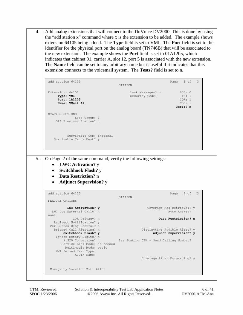
4. Add analog extensions that will connect to the DuVoice DV2000. This is done by using the “add station x” command where x is the extension to be added. The example shows extension 64105 being added. The Type field is set to VMI. The Port field is set to the identifier for the physical port on the analog board (TN746B) that will be associated to the new extension. The example shows the Port field is set to 01A1205, which indicates that cabinet 01, carrier A, slot 12, port 5 is associated with the new extension. The Name field can be set to any arbitrary name but is useful if it indicates that this extension connects to the voicemail system. The Tests? field is set to n.
5. On Page 2 of the same command, verify the following settings: • LWC Activation? y • Switchhook Flash? y • Data Restriction? n • Adjunct Supervision? y
add station 64105 Page 1 of 3 STATION Extension: 64105 Lock Messages? n BCC: 0 Type: VMI Security Code: TN: 1 Port: 1A1205 COR: 1 Name: VMail A1 COS: 1 Tests? n STATION OPTIONS Loss Group: 1 Off Premises Station? n Survivable COR: internal Survivable Trunk Dest? y
add station 64105 Page 2 of 3 STATION FEATURE OPTIONS LWC Activation? y Coverage Msg Retrieval? y LWC Log External Calls? n Auto Answer: none CDR Privacy? n Data Restriction? n Redirect Notification? y Per Button Ring Control? n Bridged Call Alerting? n Distinctive Audible Alert? y Switchhook Flash? y Adjunct Supervision? y Ignore Rotary Digits? n H.320 Conversion? n Per Station CPN - Send Calling Number? Service Link Mode: as-needed Multimedia Mode: basic MWI Served User Type: AUDIX Name: Coverage After Forwarding? s Emergency Location Ext: 64105
CTM; Reviewed: SPOC 1/23/2006
Solution & Interoperability Test Lab Application Notes ©2006 Avaya Inc. All Rights Reserved.
6 of 41 DV2000-ACM-Ana
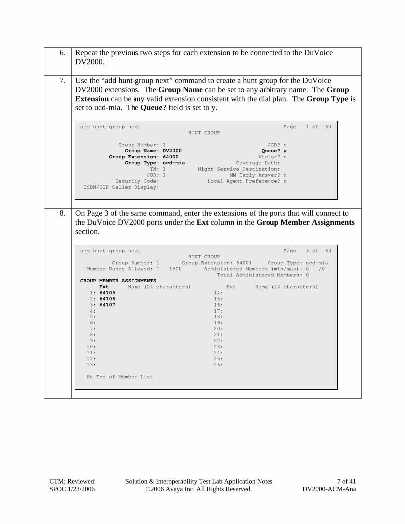
6. Repeat the previous two steps for each extension to be connected to the DuVoice DV2000.
7. Use the “add hunt-group next” command to create a hunt group for the DuVoice DV2000 extensions. The Group Name can be set to any arbitrary name. The Group Extension can be any valid extension consistent with the dial plan. The Group Type is set to ucd-mia. The Queue? field is set to y.
8. O
ts
CTM; RevSPOC 1/2
add hunt-group next Page 1 of 60 HUNT GROUP Group Number: 1 ACD? n Group Name: DV2000 Queue? y Group Extension: 64000 Vector? n Group Type: ucd-mia Coverage Path: TN: 1 Night Service Destination: COR: 1 MM Early Answer? n Security Code: Local Agent Preference? n ISDN/SIP Caller Display:
n Page 3 of the same command, enter the extensions of the ports that will connect to he DuVoice DV2000 ports under the Ext column in the Group Member Assignments ection.
add hunt-group next Page 3 of 60 HUNT GROUP Group Number: 1 Group Extension: 64001 Group Type: ucd-mia Member Range Allowed: 1 - 1500 Administered Members (min/max): 0 /0 GROUP MEMBER ASSIGNMENTS
Total Administered Members: 0
Ext Name (24 characters) Ext Name (24 characters) 1: 64105 14: 2: 64106 15: 3: 64107 16: 4: 17: 5: 18: 6: 19: 7: 20: 8: 21: 9: 22: 10: 23: 11: 24: 12: 25: 13: 26: At End of Member List
iewed:
3/2006 Solution & Interoperability Test Lab Application Notes
©2006 Avaya Inc. All Rights Reserved. 7 of 41
DV2000-ACM-Ana
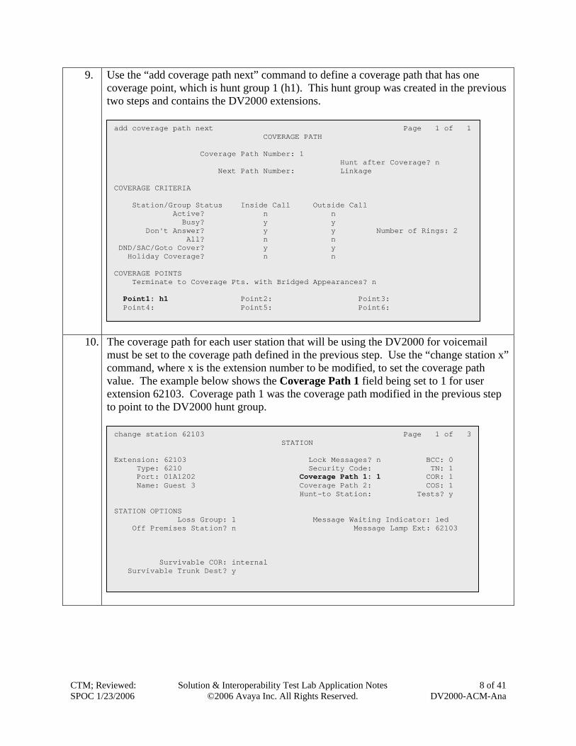
9. Use the “add coverage path next” command to define a coverage path that has one coverage point, which is hunt group 1 (h1). This hunt group was created in the previous two steps and contains the DV2000 extensions.
10. T
mcvet
CTM; RevSPOC 1/2
add coverage path next Page 1 of 1 COVERAGE PATH Coverage Path Number: 1 Hunt after Coverage? n Next Path Number: Linkage COVERAGE CRITERIA Station/Group Status Inside Call Outside Call Active? n n Busy? y y Don't Answer? y y Number of Rings: 2 All? n n DND/SAC/Goto Cover? y y Holiday Coverage? n n COVERAGE POINTS Terminate to Coverage Pts. with Bridged Appearances? n Point1: h1 Point2: Point3: Point4: Point5: Point6:
he coverage path for each user station that will be using the DV2000 for voicemail ust be set to the coverage path defined in the previous step. Use the “change station x”
ommand, where x is the extension number to be modified, to set the coverage path alue. The example below shows the Coverage Path 1 field being set to 1 for user xtension 62103. Coverage path 1 was the coverage path modified in the previous step o point to the DV2000 hunt group.
change station 62103 Page 1 of 3 STATION Extension: 62103 Lock Messages? n BCC: 0 Type: 6210 Security Code: TN: 1 Port: 01A1202 Coverage Path 1: 1 COR: 1 Name: Guest 3 Coverage Path 2: COS: 1 Hunt-to Station: Tests? y STATION OPTIONS Loss Group: 1 Message Waiting Indicator: led Off Premises Station? n Message Lamp Ext: 62103 Survivable COR: internal Survivable Trunk Dest? y
iewed:
3/2006 Solution & Interoperability Test Lab Application Notes
©2006 Avaya Inc. All Rights Reserved. 8 of 41
DV2000-ACM-Ana
4. Configure DuVoice DV2000 This section describes the configuration of the DuVoice DV2000 for connection to Avaya Communication Manager using analog mode code integration. Step Description
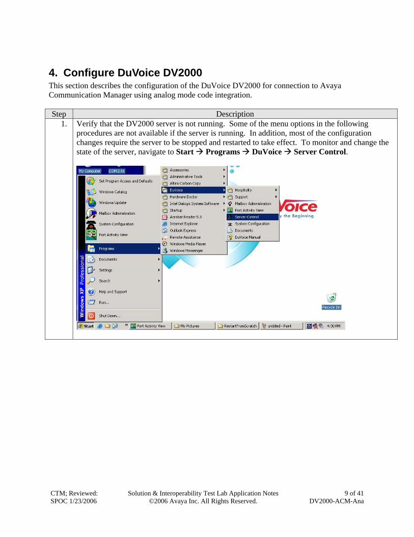
1. Verify that the DV2000 server is not running. Some of the menu options in the following procedures are not available if the server is running. In addition, most of the configuration changes require the server to be stopped and restarted to take effect. To monitor and change the state of the server, navigate to Start Programs DuVoice Server Control.
CTM; Reviewed: SPOC 1/23/2006
Solution & Interoperability Test Lab Application Notes ©2006 Avaya Inc. All Rights Reserved.
9 of 41 DV2000-ACM-Ana
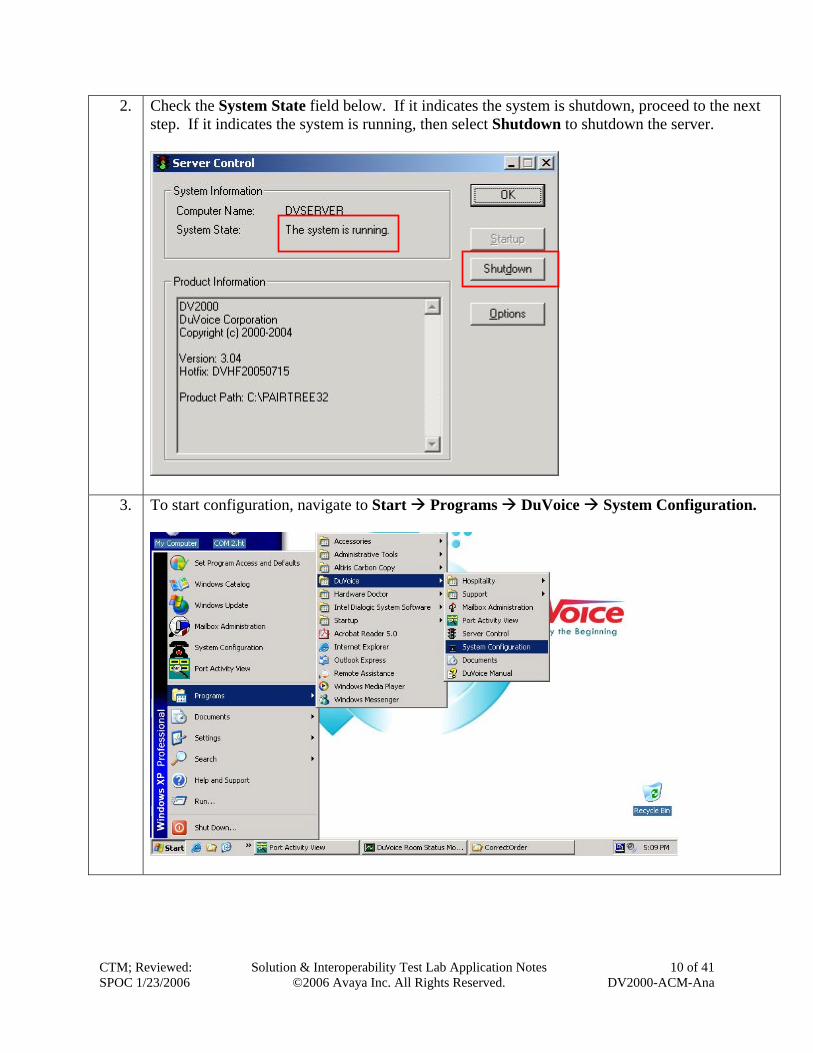
2. Check the System State field below. If it indicates the system is shutdown, proceed to the next step. If it indicates the system is running, then select Shutdown to shutdown the server.
3. To start configuration, navigate to Start Programs DuVoice System Configuration.
CTM; Reviewed: SPOC 1/23/2006
Solution & Interoperability Test Lab Application Notes ©2006 Avaya Inc. All Rights Reserved.
10 of 41 DV2000-ACM-Ana
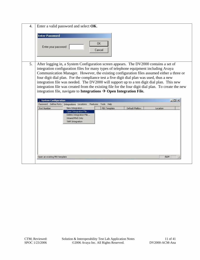
4. Enter a valid password and select OK.
5. After logging in, a System Configuration screen appears. The DV2000 contains a set of integration configuration files for many types of telephone equipment including Avaya Communication Manager. However, the existing configuration files assumed either a three or four digit dial plan. For the compliance test a five digit dial plan was used, thus a new integration file was needed. The DV2000 will support up to a ten digit dial plan. This new integration file was created from the existing file for the four digit dial plan. To create the new integration file, navigate to Integrations Open Integration File.
CTM; Reviewed: SPOC 1/23/2006
Solution & Interoperability Test Lab Application Notes ©2006 Avaya Inc. All Rights Reserved.
11 of 41 DV2000-ACM-Ana
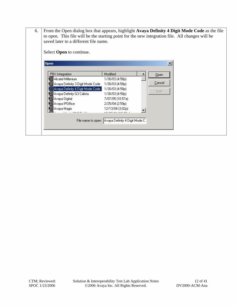
6. From the Open dialog box that appears, highlight Avaya Definity 4 Digit Mode Code as the file to open. This file will be the starting point for the new integration file. All changes will be saved later to a different file name. Select Open to continue.
CTM; Reviewed: SPOC 1/23/2006
Solution & Interoperability Test Lab Application Notes ©2006 Avaya Inc. All Rights Reserved.
12 of 41 DV2000-ACM-Ana
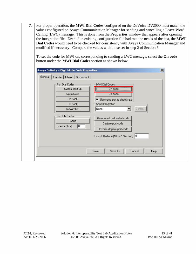
7. For proper operation, the MWI Dial Codes configured on the DuVoice DV2000 must match the values configured on Avaya Communication Manager for sending and cancelling a Leave Word Calling (LWC) message. This is done from the Properties window that appears after opening the integration file. Even if an existing configuration file had met the needs of the test, the MWI Dial Codes would need to be checked for consistency with Avaya Communication Manager and modified if necessary. Compare the values with those set in step 2 of Section 3. To set the code for MWI on, corresponding to sending a LWC message, select the On code button under the MWI Dial Codes section as shown below.
CTM; Reviewed: SPOC 1/23/2006
Solution & Interoperability©2006 Avaya Inc.
Test Lab Application Notes All Rights Reserved.
13 of 41 DV2000-ACM-Ana
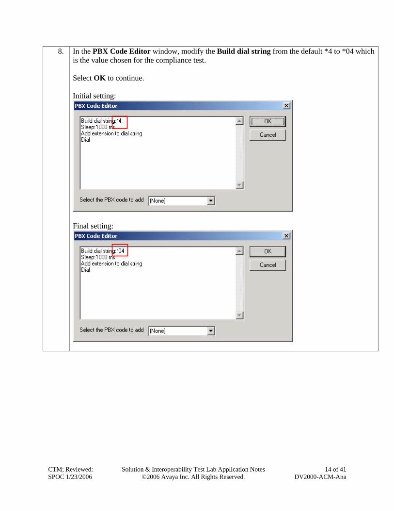
8. In the PBX Code Editor window, modify the Build dial string from the default *4 to *04 which is the value chosen for the compliance test. Select OK to continue. Initial setting:
Final setting:
CTM; Reviewed: SPOC 1/23/2006
Solution & Interoperability Test Lab Application Notes
©2006 Avaya Inc. All Rights Reserved. 14 of 41
DV2000-ACM-Ana
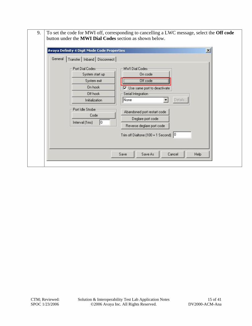
9. To set the code for MWI off, corresponding to cancelling a LWC message, select the Off code button under the MWI Dial Codes section as shown below.
CTM; Reviewed: SPOC 1/23/2006
Solution & Interoperability©2006 Avaya Inc.
Test Lab Application Notes All Rights Reserved.
15 of 41 DV2000-ACM-Ana
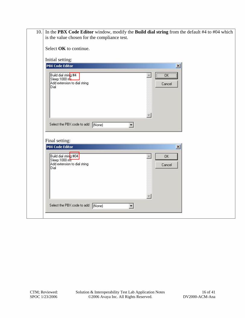
10. In the PBX Code Editor window, modify the Build dial string from the default #4 to #04 which is the value chosen for the compliance test. Select OK to continue. Initial setting:
Final setting:
CTM; Reviewed: SPOC 1/23/2006
Solution & Interoperability Test Lab Application Notes ©2006 Avaya Inc. All Rights Reserved.
16 of 41 DV2000-ACM-Ana
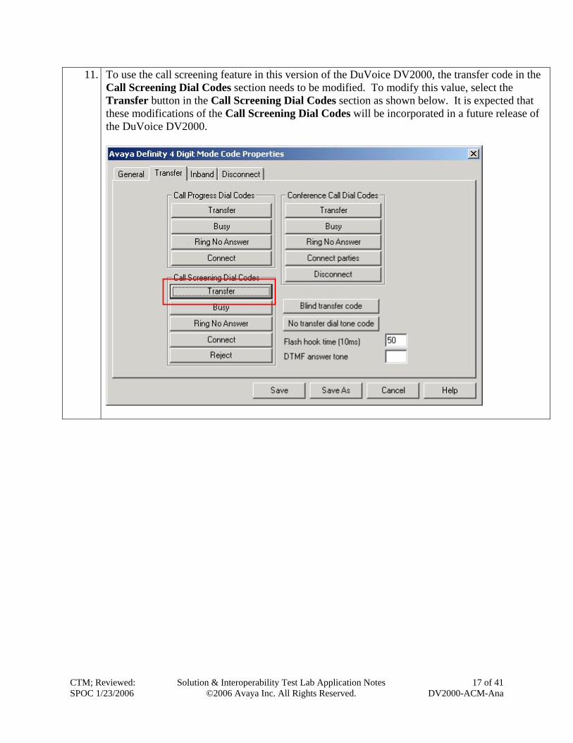
11. To use the call screening feature in this version of the DuVoice DV2000, the transfer code in the Call Screening Dial Codes section needs to be modified. To modify this value, select the Transfer button in the Call Screening Dial Codes section as shown below. It is expected that these modifications of the Call Screening Dial Codes will be incorporated in a future release of the DuVoice DV2000.
CTM; Reviewed: SPOC 1/23/2006
Solution & Interoperability Test Lab Application Notes ©2006 Avaya Inc. All Rights Reserved.
17 of 41 DV2000-ACM-Ana
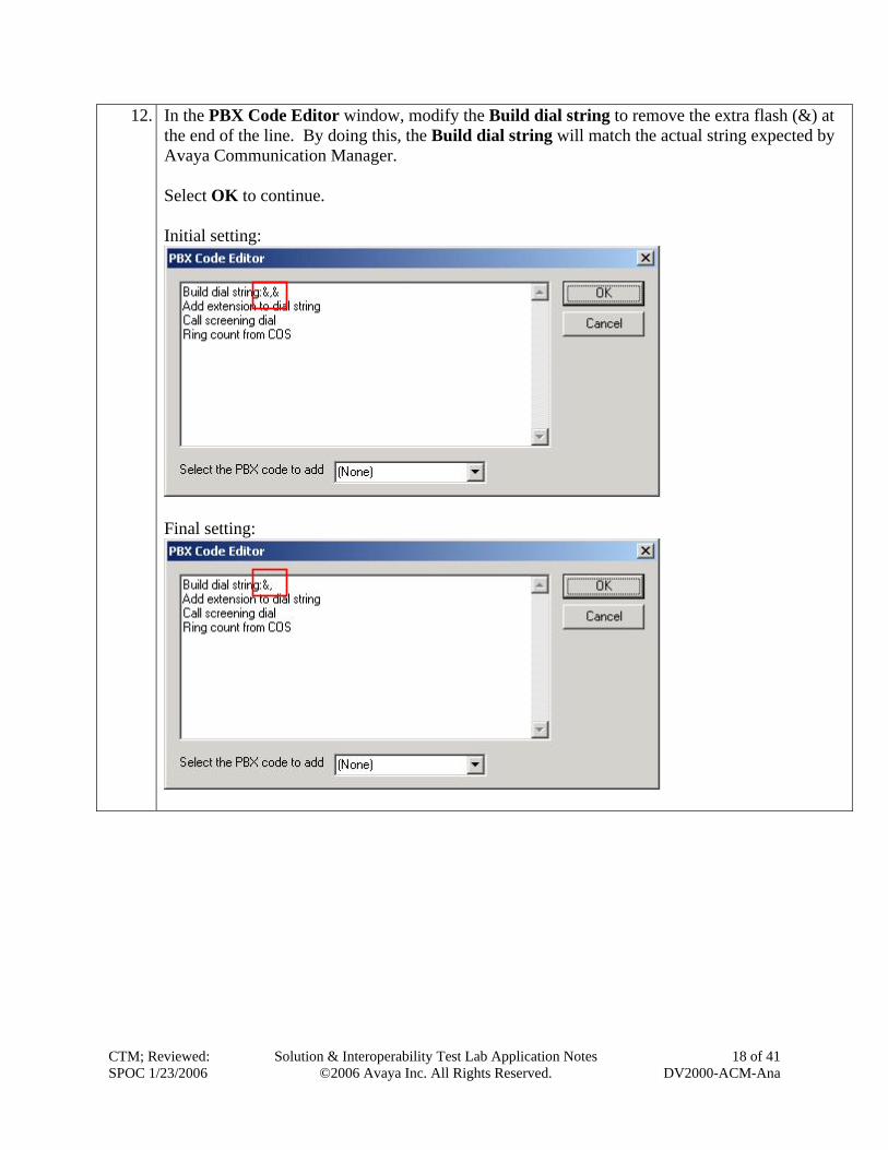
12. In the PBX Code Editor window, modify the Build dial string to remove the extra flash (&) at the end of the line. By doing this, the Build dial string will match the actual string expected by Avaya Communication Manager. Select OK to continue. Initial setting:
Final setting:
CTM; Reviewed: SPOC 1/23/2006
Solution & Interoperability Test Lab Application Notes
©2006 Avaya Inc. All Rights Reserved. 18 of 41
DV2000-ACM-Ana
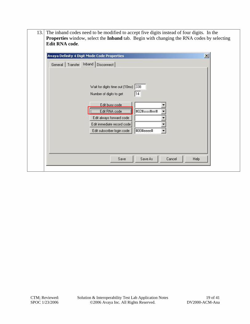
13. The inband codes need to be modified to accept five digits instead of four digits. In the Properties window, select the Inband tab. Begin with changing the RNA codes by selecting Edit RNA code.
CTM; Reviewed: SPOC 1/23/2006
Solution & Interoperability Test Lab Application Notes ©2006 Avaya Inc. All Rights Reserved.
19 of 41 DV2000-ACM-Ana
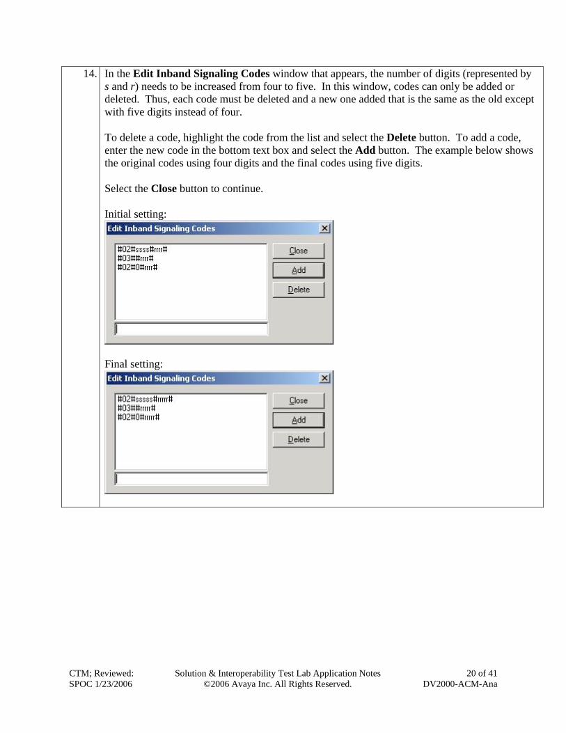
14. In the Edit Inband Signaling Codes window that appears, the number of digits (represented by s and r) needs to be increased from four to five. In this window, codes can only be added or deleted. Thus, each code must be deleted and a new one added that is the same as the old except with five digits instead of four. To delete a code, highlight the code from the list and select the Delete button. To add a code, enter the new code in the bottom text box and select the Add button. The example below shows the original codes using four digits and the final codes using five digits. Select the Close button to continue. Initial setting:
Final setting:
CTM; Reviewed: SPOC 1/23/2006
Solution & Interoperability Test Lab Application Notes ©2006 Avaya Inc. All Rights Reserved.
20 of 41 DV2000-ACM-Ana
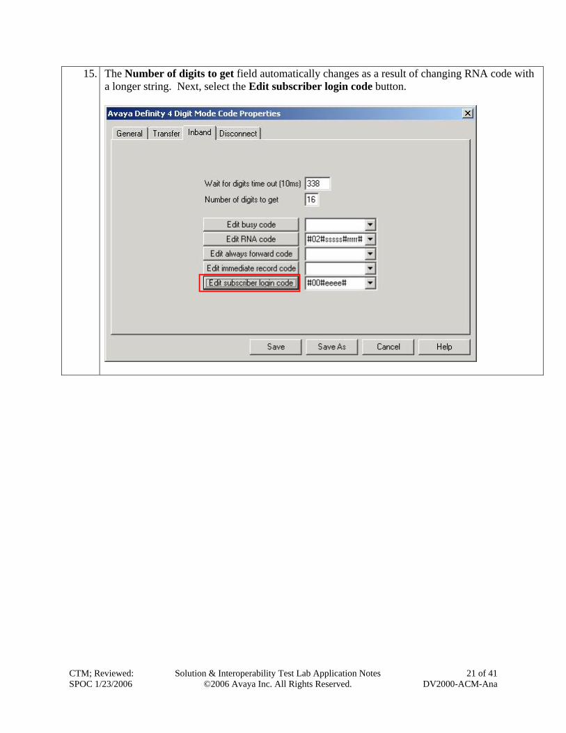
15. The Number of digits to get field automatically changes as a result of changing RNA code with a longer string. Next, select the Edit subscriber login code button.
CTM; Reviewed: SPOC 1/23/2006
Solutio
n & Interoperability Test Lab Application Notes ©2006 Avaya Inc. All Rights Reserved.
21 of 41 DV2000-ACM-Ana
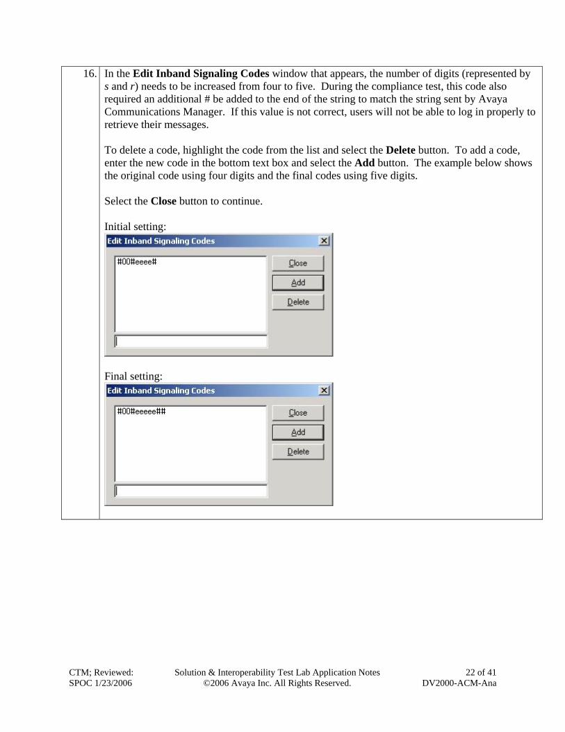
16. In the Edit Inband Signaling Codes window that appears, the number of digits (represented by s and r) needs to be increased from four to five. During the compliance test, this code also required an additional # be added to the end of the string to match the string sent by Avaya Communications Manager. If this value is not correct, users will not be able to log in properly to retrieve their messages. To delete a code, highlight the code from the list and select the Delete button. To add a code, enter the new code in the bottom text box and select the Add button. The example below shows the original code using four digits and the final codes using five digits. Select the Close button to continue. Initial setting:
Final setting:
CTM; Reviewed: SPOC 1/23/2006
Solution & Interoperability Test Lab Application Notes ©2006 Avaya Inc. All Rights Reserved.
22 of 41 DV2000-ACM-Ana
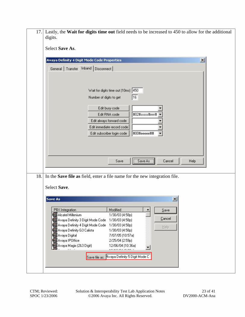
17. Lastly, the Wait for digits time out field needs to be increased to 450 to allow for the additional digits. Select Save As.
18. In the Save file as field, enter a file name for the new integration file. Select Save.
CTM; Reviewed: SPOC 1/23/2006
Solutio
n & Interoperability Test Lab Application Notes ©2006 Avaya Inc. All Rights Reserved.
23 of 41 DV2000-ACM-Ana
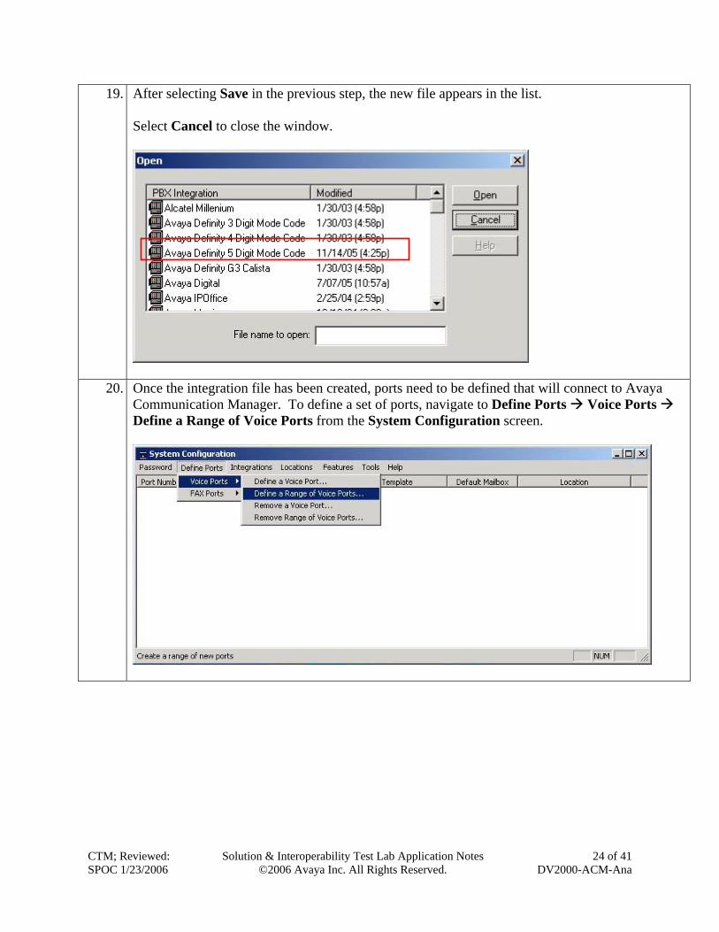
19. After selecting Save in the previous step, the new file appears in the list. Select Cancel to close the window.
20. Once the integration file has been created, ports need to be defined that will connect to Avaya Communication Manager. To define a set of ports, navigate to Define Ports Voice Ports Define a Range of Voice Ports from the System Configuration screen.
CTM; Reviewed: SPOC 1/23/2006
Solution & Interoperability Test Lab Application Notes ©2006 Avaya Inc. All Rights Reserved.
24 of 41 DV2000-ACM-Ana
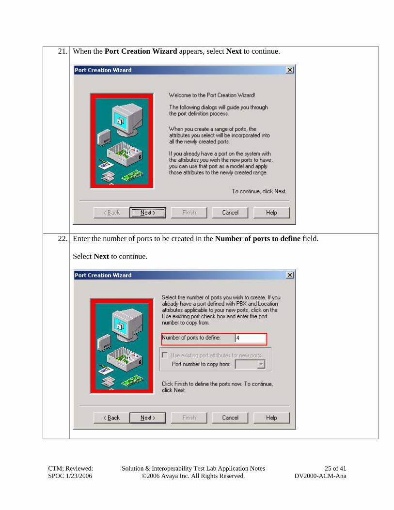
21. When the Port Creation Wizard appears, select Next to continue.
22. Enter the number of ports to be created in the Number of ports to define field. Select Next to continue.
CTM; Reviewed: SPOC 1/23/2006
Solution & Interoperability Test Lab Application Notes ©2006 Avaya Inc. All Rights Reserved.
25 of 41 DV2000-ACM-Ana
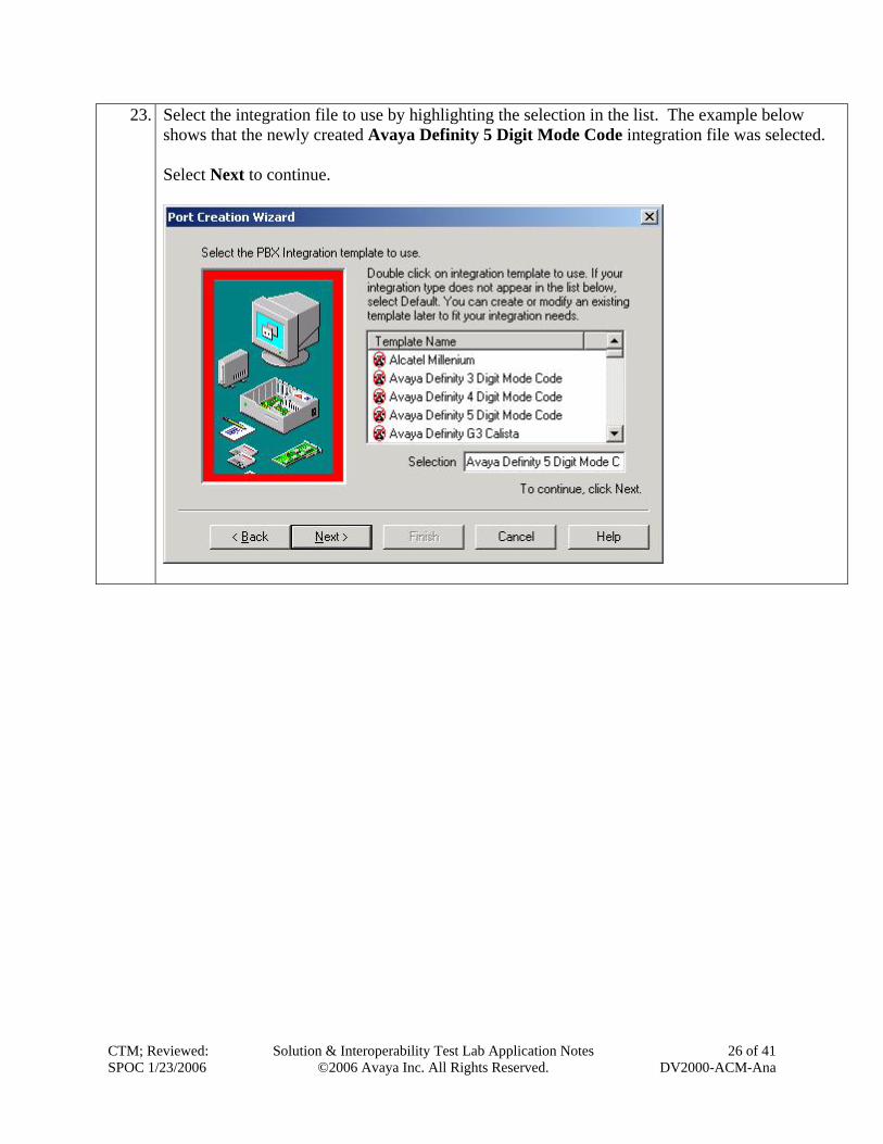
23. Select the integration file to use by highlighting the selection in the list. The example below shows that the newly created Avaya Definity 5 Digit Mode Code integration file was selected. Select Next to continue.
CTM; Reviewed: SPOC 1/23/2006
Solution & Interoperability Test Lab Application Notes ©2006 Avaya Inc. All Rights Reserved.
26 of 41 DV2000-ACM-Ana
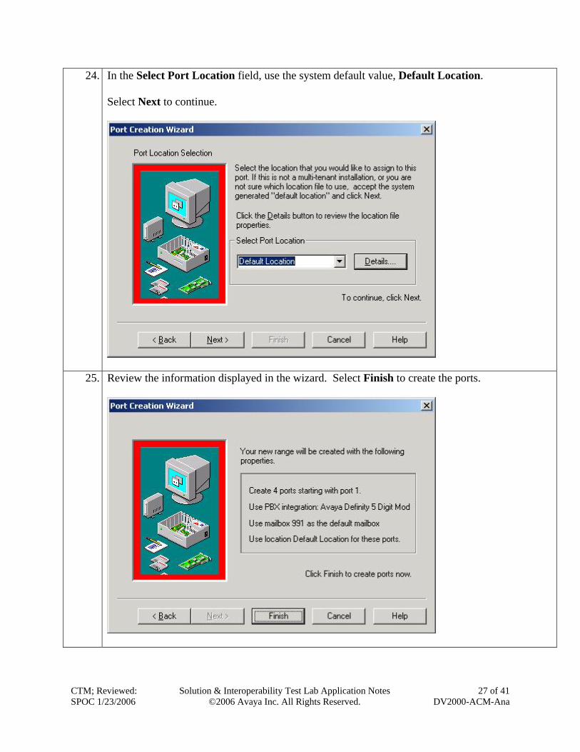
24. In the Select Port Location field, use the system default value, Default Location. Select Next to continue.
25. Review the information displayed in the wizard. Select Finish to create the ports.
CTM; Reviewed: SPOC 1/23/2006
Solution & Interoperability Test Lab Application Notes ©2006 Avaya Inc. All Rights Reserved.
27 of 41 DV2000-ACM-Ana
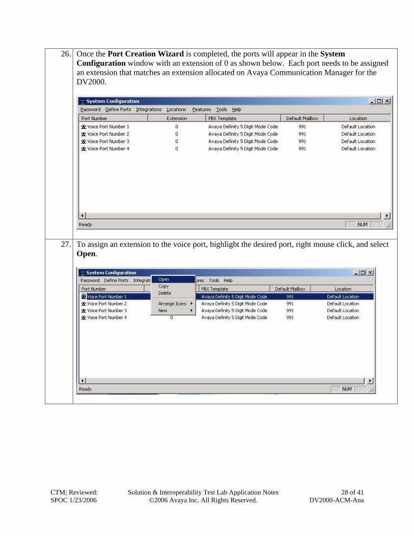
26. Once the Port Creation Wizard is completed, the ports will appear in the System Configuration window with an extension of 0 as shown below. Each port needs to be assigned an extension that matches an extension allocated on Avaya Communication Manager for the DV2000.
27. To assign an extension to the voice port, highlight the desired port, right mouse click, and select Open.
CTM; Reviewed: SPOC 1/23/2006
Solution & Interoperability Test Lab Application Notes ©2006 Avaya Inc. All Rights Reserved.
28 of 41 DV2000-ACM-Ana
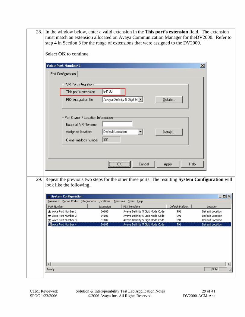
28. In the window below, enter a valid extension in the This port’s extension field. The extension must match an extension allocated on Avaya Communication Manager for theDV2000. Refer to step 4 in Section 3 for the range of extensions that were assigned to the DV2000. Select OK to continue.
29. Repeat t
look like
CTM; Reviewed: SPOC 1/23/2006
he previous two steps for the other three ports. The resulting System Configuration will the following.
Solution & Interoperability Test Lab Application Notes
©2006 Avaya Inc. All Rights Reserved. 29 of 41
DV2000-ACM-Ana
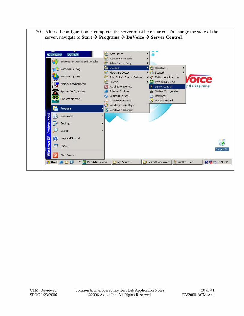
30. After all configuration is complete, the server must be restarted. To change the state of the server, navigate to Start Programs DuVoice Server Control.
CTM; Reviewed: SPOC 1/23/2006
Solution & Interoperability Test Lab Application Notes ©2006 Avaya Inc. All Rights Reserved.
30 of 41 DV2000-ACM-Ana
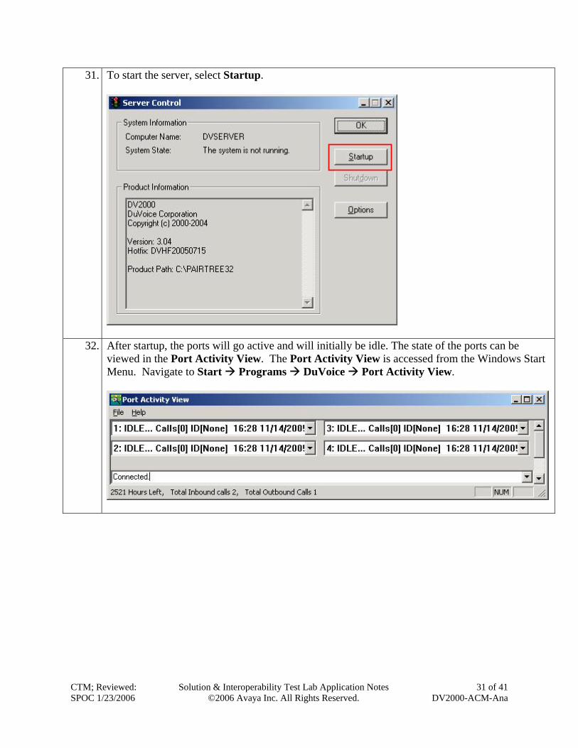
31. To start the server, select Startup.
32. After startup, the ports will go active and will initially be idle. The state of the ports can be viewed in the Port Activity View. The Port Activity View is accessed from the Windows Start Menu. Navigate to Start Programs DuVoice Port Activity View.
CTM; Reviewed: SPOC 1/23/2006
Solution & Interoperability Test Lab Application Notes ©2006 Avaya Inc. All Rights Reserved.
31 of 41 DV2000-ACM-Ana
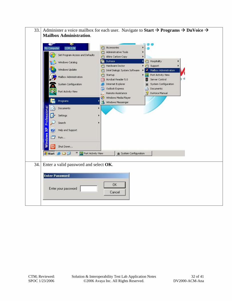
33. Administer a voice mailbox for each user. Navigate to Start Programs DuVoice Mailbox Administration.
34. Enter a valid password and select OK.
CTM; Reviewed: SPOC 1/23/2006
Solution & Interoperability Test Lab Application Notes ©2006 Avaya Inc. All Rights Reserved.
32 of 41 DV2000-ACM-Ana
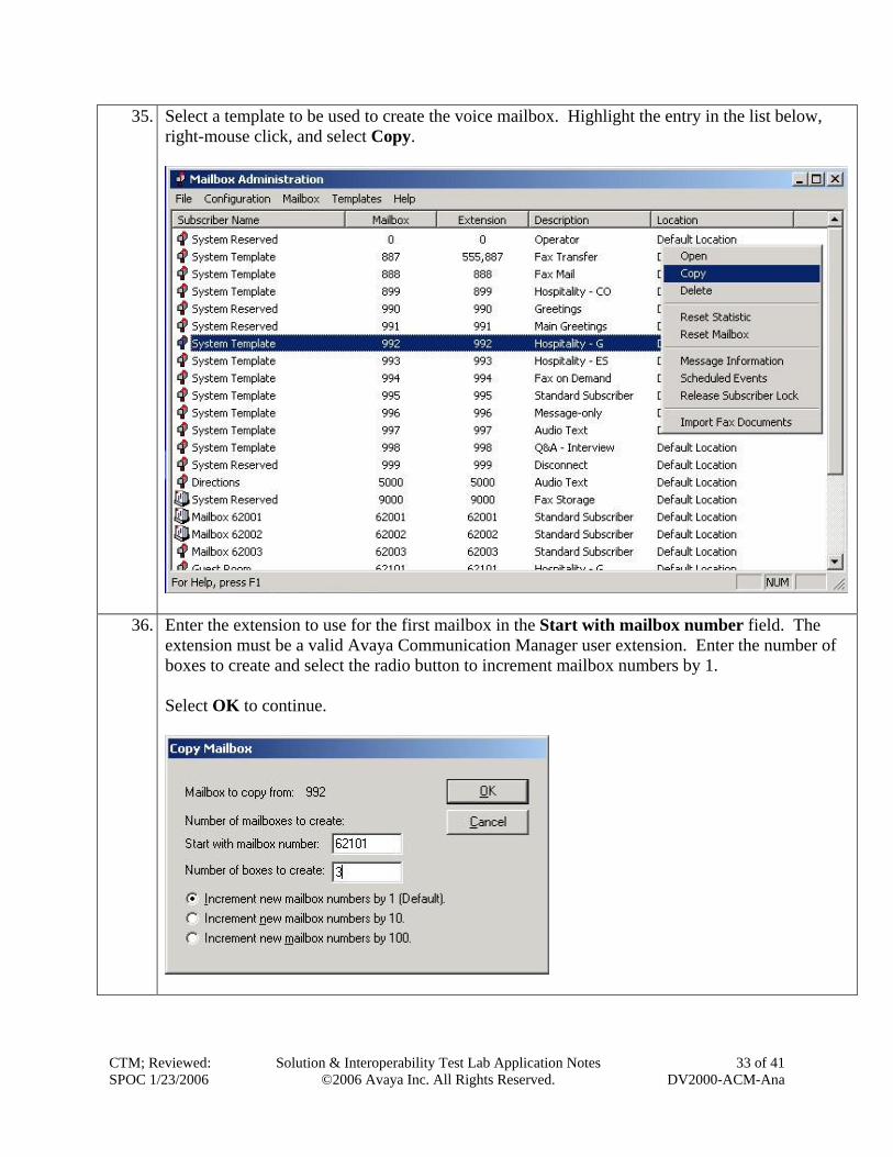
35. Select a template to be used to create the voice mailbox. Highlight the entry in the list below, right-mouse click, and select Copy.
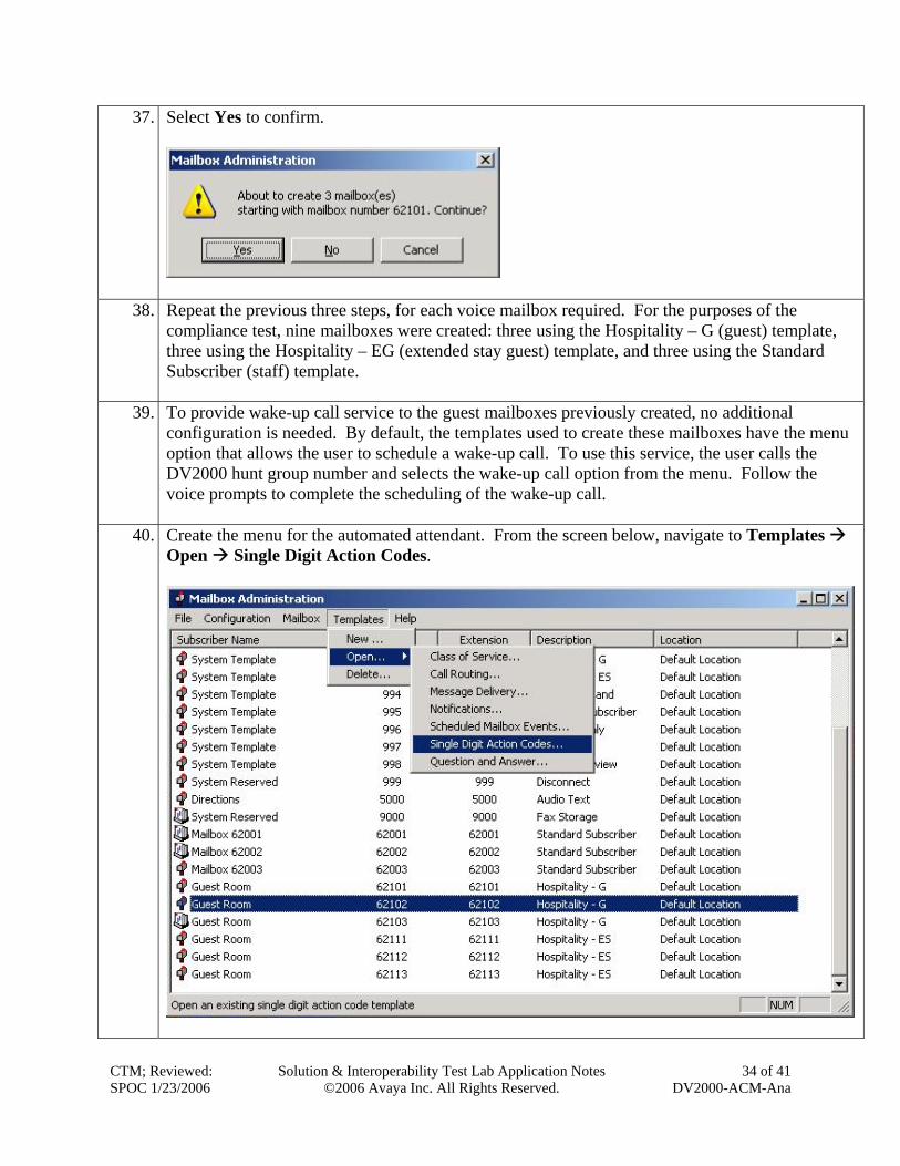
36. Enter the extension to use for the first mailbox in the Start with mailbox number field. The extension must be a valid Avaya Communication Manager user extension. Enter the number of boxes to create and select the radio button to increment mailbox numbers by 1. Select OK to continue.
CTM; Reviewed: SPOC 1/23/2006
Solution & Interoperability Test Lab Application Notes ©2006 Avaya Inc. All Rights Reserved.
33 of 41 DV2000-ACM-Ana
37. Select Yes to confirm.
38. Repeat the previous three steps, for each voice mailbox required. For the purposes of the compliance test, nine mailboxes were created: three using the Hospitality – G (guest) template, three using the Hospitality – EG (extended stay guest) template, and three using the Standard Subscriber (staff) template.
39. To provide wake-up call service to the guest mailboxes previously created, no additional configuration is needed. By default, the templates used to create these mailboxes have the menu option that allows the user to schedule a wake-up call. To use this service, the user calls the DV2000 hunt group number and selects the wake-up call option from the menu. Follow the voice prompts to complete the scheduling of the wake-up call.
40. Create the menu for the automated attendant. From the screen below, navigate to Templates Open Single Digit Action Codes.
CTM; Reviewed: SPOC 1/23/2006
Solution & Interoperability Test Lab Application Notes ©2006 Avaya Inc. All Rights Reserved.
34 of 41 DV2000-ACM-Ana
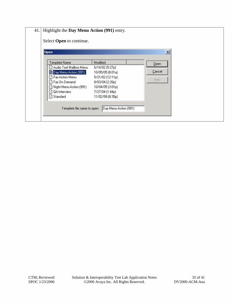
41. Highlight the Day Menu Action (991) entry. Select Open to continue.
CTM; Reviewed: SPOC 1/23/2006
Solution & Interoperability Test Lab Application Notes ©2006 Avaya Inc. All Rights Reserved.
35 of 41 DV2000-ACM-Ana
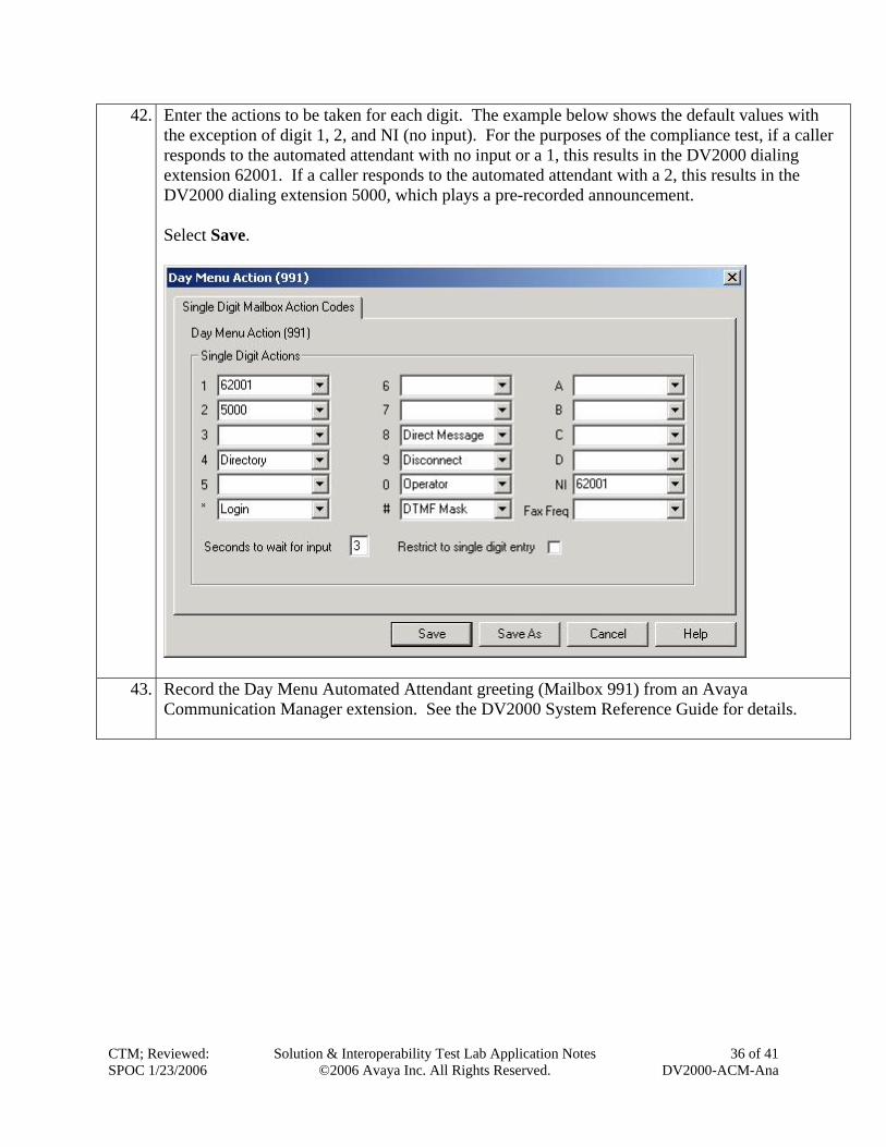
42. Enter the actions to be taken for each digit. The example below shows the default values with the exception of digit 1, 2, and NI (no input). For the purposes of the compliance test, if a caller responds to the automated attendant with no input or a 1, this results in the DV2000 dialing extension 62001. If a caller responds to the automated attendant with a 2, this results in the DV2000 dialing extension 5000, which plays a pre-recorded announcement. Select Save.
43. Record the Day Menu Automated Attendant greeting (Mailbox 991) from an Avaya Communication Manager extension. See the DV2000 System Reference Guide for details.
CTM; Reviewed: SPOC 1/23/2006
Solution & Interoperability Test Lab Application Notes ©2006 Avaya Inc. All Rights Reserved.
36 of 41 DV2000-ACM-Ana
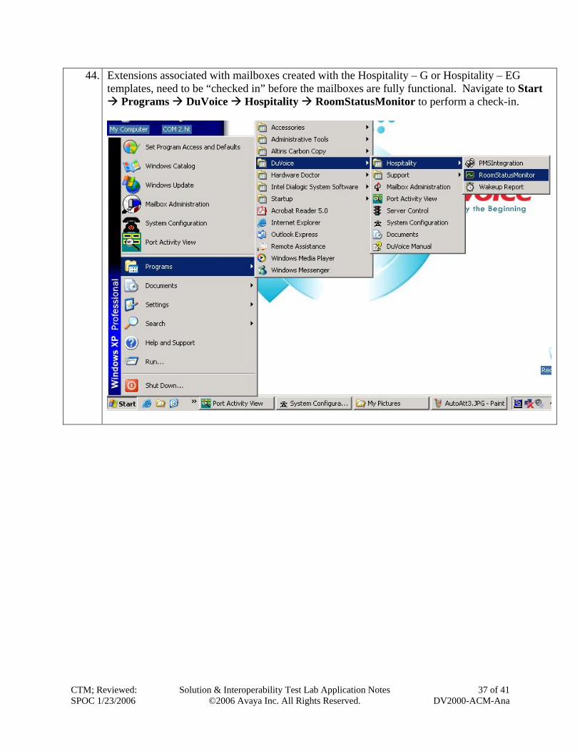
44. Extensions associated with mailboxes created with the Hospitality – G or Hospitality – EG templates, need to be “checked in” before the mailboxes are fully functional. Navigate to Start
Programs DuVoice Hospitality RoomStatusMonitor to perform a check-in.
CTM; Reviewed: SPOC 1/23/2006
Solution & Interoperability Test Lab Application Notes ©2006 Avaya Inc. All Rights Reserved.
37 of 41 DV2000-ACM-Ana
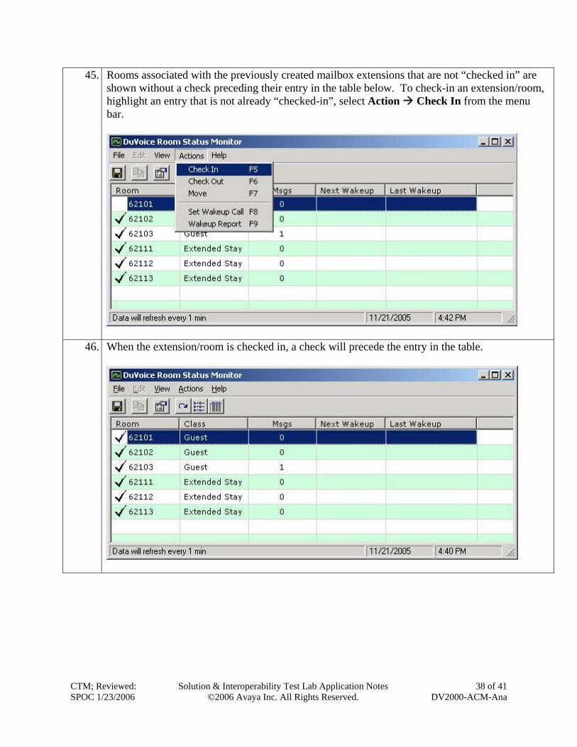
45. Rooms associated with the previously created mailbox extensions that are not “checked in” are shown without a check preceding their entry in the table below. To check-in an extension/room, highlight an entry that is not already “checked-in”, select Action Check In from the menu bar.
46. When the extension/room is checked in, a check will precede the entry in the table.
CTM; Reviewed: SPOC 1/23/2006
Solution & Interoperability Test Lab Application Notes ©2006 Avaya Inc. All Rights Reserved.
38 of 41 DV2000-ACM-Ana
CTM; Reviewed: SPOC 1/23/2006
Solution & Interoperability Test Lab Application Notes ©2006 Avaya Inc. All Rights Reserved.
39 of 41 DV2000-ACM-Ana
5. Interoperability Compliance Testing The interoperability compliance testing included feature, serviceability and performance testing. The feature testing focused on exercising the core features of the DV2000 to validate the integration interface to Avaya Communication Manager. This included the automated attendant, voicemail, wakeup call and performing guest check-in and checkout using the Room Status Monitor functionality. The serviceability testing introduced failure scenarios to verify operation of the DuVoice DV2000 after failure recovery. The performance test generated bulk call volumes to verify operation under load conditions.
5.1. General Test Approach The general test approach was to manually place intra-switch calls and inbound trunk calls that were ultimately answered by the DuVoice DV2000. Depending on the type of call, the user then had the option to leave a voicemail message, retrieve a voicemail message, schedule a wake-up call or transfer to another extension. All inbound calls were routed by Avaya Communication Manager to the DuVoice DV2000 hunt group, which were answered by the DV2000 with the automated attendant greeting. Internal calls that were unanswered were covered to the DV2000 hunt group. The DV2000 would answer these calls with the voice mailbox greeting of the subscriber extension. Lastly, internal calls placed to the DV2000 directly were answered by the DV2000 with the voicemail menu of the originating extension with an option to retrieve messages. For serviceability testing, the DV2000 and Avaya Communication Manager were each restarted separately. For performance testing, a call generator was used to place calls, leave voicemail and retrieve voicemail over an extended period of time.
5.2. Test Results All test cases passed. The DuVoice DV2000 properly interpreted the analog mode codes sent by Avaya Communication Manager in each of the call scenarios and responded as expected. Voicemail messages could be recorded and retrieved. It was verified that the Message Waiting Indicator was activated when a new message was left and was deactivated when the message was retrieved. The DuVoice DV2000 was able to resume processing of calls after being restarted and after Avaya Communication Manager was restarted. Performance testing verified proper operation of the DV2000 while under load.
6. Verification Steps The following steps may be used to verify the configuration:
• Verify that calls are routed properly to the DV2000 hunt group and that mode codes are being sent. Connect an analog phone to one of the extensions assigned to the DV2000 hunt group. Dial this extension from another phone on Avaya Communication Manager. Verify the phone rings and then answer the call. Verify that several DTMF tones are heard prior to the voice path being connected.
• Verify that users can leave voice messages. Place an internal call to an extension with a mailbox on the DV2000 and let the call go to coverage. Verify that the caller is
CTM; Reviewed: SPOC 1/23/2006
Solution & Interoperability Test Lab Application Notes ©2006 Avaya Inc. All Rights Reserved.
40 of 41 DV2000-ACM-Ana
connected to the voice mailbox of the destination extension and record a message. Verify that the Message Waiting Indicator is activated on the recipient extension.
• Verify that users can access their voice mailboxes. From an extension with a mailbox on the DV2000 that has an active Message Waiting Indicator, call the DV2000 hunt group extension. Verify that the user is connected to the voice mailbox for that extension and can retrieve the message. Verify the Message Waiting Indicator is deactivated.
• Verify the operation of the automated attendant. Place an inbound call that is routed to the DV2000 hunt group. Verify that the caller is connected to the automated attendant and hears the main greeting menu.
7. Support Technical support for the DuVoice DV2000 can be obtained by contacting the DuVoice Customer Service Center at (425) 250-2393. Technical support can also be contacted via email at [email protected].
8. Conclusion These Application Notes describe the procedures for configuring the DuVoice DV2000 to integrate with Avaya Communication Manager using analog mode codes. The DuVoice DV2000 successfully passed all compliance testing.
9. Additional References The following Avaya product documentation can be found at http://support.avaya.com. [1] Feature Description and Implementation For Avaya Communication Manager, Release 3.0, Issue 3.0, June 2005, Document Number 555-245-205 [2] Administrator Guide for Avaya Communication Manager, Release 3.0, Issue 1.0, June 2005, Document Number 03-300509 The following DuVoice DV2000 product documentation is available from DuVoice. Visit the website at http://www.duvoice.com for company and product information. [3] DuVoice System Reference Guide
CTM; Reviewed: SPOC 1/23/2006
Solution & Interoperability Test Lab Application Notes ©2006 Avaya Inc. All Rights Reserved.
41 of 41 DV2000-ACM-Ana
©2006 Avaya Inc. All Rights Reserved. Avaya and the Avaya Logo are trademarks of Avaya Inc. All trademarks identified by ® and ™ are registered trademarks or trademarks, respectively, of Avaya Inc. All other trademarks are the property of their respective owners. The information provided in these Application Notes is subject to change without notice. The configurations, technical data, and recommendations provided in these Application Notes are believed to be accurate and dependable, but are presented without express or implied warranty. Users are responsible for their application of any products specified in these Application Notes. Please e-mail any questions or comments pertaining to these Application Notes along with the full title name and filename, located in the lower right corner, directly to the Avaya DeveloperConnection Program at [email protected].