Embed Size (px)
Citation preview

NASA Technical Memorandum. L0_5_3!9
Application of Artificial Neural Networksin Nonlinear Analysis of Trusses
J. Alam
Youngstown State UniversityYoungstown, Ohio
and
L. Berke
Lewis Research Center
Cleveland, Ohio
w ": " c -
November 1991
N/ A
(NASA-T_- 105319) APPLICATION OF
ARTIFICIAL NEURAL NETWORKS IN
NONLINEAR ANALYSIS OF TRUSSFS
(NASA) _7 p
N93-I1403
Unc1 as
G3/39 0126281

_ _,F,="_ _ _4 "_

APPLICATION OF ARTIFICIAL NEURAL NETWORKS IN
NONLINEAR ANALYSIS OF TRUSSES
J. Alam
Youngstown State University
Civil Engineering Department
Youngstown, Ohio 44555
and
L. Berke
National Aeronautics and Space AdministrationLewis Research Center
Cleveland, Ohio 44135
SUMMARY
In the present study, a method is developed to incorporate neural network models for
material response into nonlinear elastic truss analysis. Different feedforward network configura-tions are developed to assess the accuracy of neural network modeling of nonlinear material re-
sponse. In addition to this, a scheme based upon linear interpolation for material data, is also
implemented for comparison purposes.
It is found that the neural network approach can yield very accurate results if used with
care. For the type of problems under consideration, it offers a viable alternative to other mate-
rial modeling methods.
INTRODUCTION
It has been an ongoing effort to create machines which are capable of exhibiting intelligent
behavior. The research in the Artificial Intelligence (AI) area is directed to achieve this goal.The traditional AI based approaches lead to the: development of Expert Systems. They are use-
ful in cases where a given problem can be specified in the form of well defined rules. By using
symbolic lo_ic useful inferences can be drawn from the rules data base by following standard
search techniques. However, this approach was not very successful in pattern recognition taskswhere the available information is noisy or incomplete.
Neural networks (NN), inspired by the researchin cognitive and biological sciences in the
functioning of the brain have provided an alternative approach to the solution of pattern recog-nition tasks, such as text to speech synthesis (ref. 1), image compression and processing (ref. 2),
and nonlinear signal processing (ref. 3). Several neural network models have been suggested.
ttopfield (ref. 4) was successful in applying network approach for a class of optimization prob-lems. One of the most popular neural network models is based upon the studies of Rumelhart,
Hinton, and Williams (ref. 5). It is a multi-layered feedforward network, in which learning is
accomplished by backpropagation algorithm. It has been used extensively in solving a wide
variety of problems. The computational NN models resemble the biological model of neurons.
However, this resemblance is not very close and to avoid misunderstanings, they are called Arti-
ficial Neural Nets (ANN).

The applicationof feedforwardnetworksbaseduponbackpropagationalgorithm in Com-putational StructuralTechnology(CST) is relativelynewin its origin. Rehaket al. (ref. 6)developedNN modelsfor simulatingthe dynamicbehaviorof structures. TroudetandMerrill(ref. 7) adoptednetworkmethodologyfor estimatingfatiguelife of structural components.Berkeand Hajela(ref. 8) usedANN for structural analysisandoptimization of trusses. Their
use in plate and shell analysis is reportedin reference 9. They have shown considerable promise
in material modelirig. Jain et al. (ref. 10_ used it to model thetri-axial behavior of soils.
Ghaboussi et al. (ref. 11) have reported the modeling of nonlinear behavior of concrete.
It was suggested in references 8 and 11 that the trained neural networks can be incor-
porated into existing structural analysis programs. The use of nonlinear analysis programs
require an accurate description of material behavior. With the increased complexity in modelingmaterial behavior, it is becomlng necessary to look for new approaches to represent it in a form
which is computationally efficient and can easily be added to the existing stress analysis pro-
grams, The use of ANN seems to be particularly appealing for this type of nonlinear materialsmodeling. It allows to capture the material response by training an appropriately configurednetwork for given material data. Once the network is trained for the desired accuracy a small
data file Containing tile weights of connections and network biases is saved. It can be used later
on for eliciting proper.material response Such as stresses for known strains or stress incrementsfor given strain increments. The next step would be to incorporate this trained NN into a stress
analysis program.
OBJECTIVE OF THE STUDY
The present study is conducted to explpre the possibility of training feedforward networkfor" known material data and then incorporate it into a structural analysis program considering
material nonlinearity. For this purpose, nonlinear elastic analysis of trusses is chosen. Thematerial behavior is assumed to be known in the form of equations so that comparison between
the actual material behavior and the one predicted by neural nets is possible for the evaluation
of the effectiveness of the neural network approach. Different trusses are used for analysis to
allow comparison between the different approaches."
NONLINEAR ELASTIC ANALYSIS OF TRUSSES-
A stiffnessbased matrix formulation(ref.12) isused forthe analysisoftrusses.
equilibriumequationsfora trusscan be writtenas:
[K]{u}= {f)
Tlrejoint
(1)
where [K] is overall assembled stiffness matrix of truss, {u} and {f} represent the joint displace-ment vector and joint force vector, respectively, The material behavior is given by the following
equation (ref. 13):

o=E0(.-5. )for.>0- (2)
where E0 = 200 units
For the equations dimensionally consistent units can be chosen. Due to nonlinear material
behavior in equation (2) the stiffness matrix in equation (1) is a function of displacements {u),and has to be solved in an iterative manner. The initial stiffness method as suggested in refer-
ence 13 was used. This method saves the updating of the stiffness matrix at each iteration. Thestiffness matrix formulated for the linear elastic case can be used for each iteration. This
method is more stable in comparison to the tangent stiffness method which requires updating of
the stiffness matrix at the beginning of each iteration. However, it; suffers from the slow conver-
gence rate at loads near maximum loads.
The total load is applied in n prescribed steps. The equations for the pth load step andthe ith iteration are:
where
{f,,}(4)
Thevector {fP)representsthe appliedjointforcesforthe pth load step. {AuP1 isthe
change in the jointdisplacementvectorforthe ithiterationforthe load step p. {R|}is a resi-
dual forcevectorshowlhg the errorin the jointequilibr_amdue to the forcevector {fl-l)com-
puted from the forcesin the members of the truss.The displacementsforthe i+I iterationare
updated by the followingequation:
{or+,}={.r}+
For the kth member of the trussthe elongationsare calculatedas follows:
I and m are the end jointsof the member k. The uI and U m are the x-displacements
ofjoints I and m, respectively.Similarly v's are the jointdisplacementsalong the y-direction,v isthe slopeof the kthmember with respectto the positivex-axls.The strainsin
each member ofthe trussare computed by:
3

ekk= 1,2...,s (7)
Ik
Here Ik is the length of the k th member and s is the total number of members in the
truss. The stresses in each member of the truss can now be computed by. using equation (2) or
by the trained neural network. The forces in each member are obtained from these stresses.
The member forces are transformed to obtain the equivalent joint forces to assemble the new {fl)vector. The residual force vector for the i41 iteration will be:
The new joint equilibrium equations are:
By using Gauss-Jordan method the incremental displacements are calculated and the pro-
cedure can be repeated as described earlier. To stop the iterative process an error norm given by
the following equation is calculated: '
t r
(Ri,q) 2
q=.l
r
(10)
where 5 is the rms error, and r is the total number of nonzero joint displacements in the
truss. When the calculated value of rms error 5 is less than the prescribed tolerance the
iteration process is stopped and the values of the joint displacements, member forces, stressesand strains are printed. The applied joint loads are' incremented for the next load step p+l.
This procedure is repeated until all the load steps are completed.
ARTIFICIAL NEURAL NETWORK MATERIAL MODELING
Figure 1 shows the neural network configuration. It has one processing element (PE) in
the input layer with strain as the input. The output layer consists of one PE providing thevalue of stress. The processing elements in the middle layer also, known as hidden layer, are
varied from 5 to 15 to find an appropriate network configuration which predicts stresses for a
given strain with the smallest error. The computer program NETS (ref. 14) was used for all the
network training. In the program the backpropagation algorithm was implemented at Lyndon
B. Johnson Space Flight Center of NASA.
For incorporating the neural network model of material behavior in the nonlinear truss
analysis program, two small functions, "init" and "propagate," were written in C language. The
4

first one initializes the net while the second one propagates the given input strain to get the
corresponding stress. The output oi of an ith PE can be obtained as follows:
1Oi --
I + e -aL
where Wij is the weight of the connection between PE i and PE j. Ij is the input from thejth PE and bi is the bias value in
ni
ai --_ E wijlj -t- b ij=l
(11)
(12)
for the i th PE.
RESULTS AND DISCUSSIONS
To assess the accuracy and to choose an appropriate network configuration for the non-
linear truss analysis several cases listed.below were selected for numerical experimentation.
case 1 1-5-1.13 network
case 2 1-10-1.13 network
case 3 1-15-1.13 network
case 4 1-5-1.19 network
case 5 1-10-1.19 network
In these cases the first number denotes the number of input units, which is always one.
The second number represents the number of hidden units and it varies from 5 to 15. The thirdnumber which is one in all the cases, is the number of output units. The last number after the
period is the total number of input-output pairs used for network training. These pairs are
obtained from equation (2). All the training data was scaled between 0 and 1 due to the restric-
tion placed by the backpropagation algorithm implemented in the NETS program. Scaling between0.1 and 0.9 is also customary. All the networks are-trained with a maximum error not exceeding
1.8 percent and rms error less than 1 percent. After the training the files containing weights andbiases are saved for each of the network to assess the accuracy of all the neural networks.
The input strains used for training are augmented by additional values of strains from the
stress-strain equation (2) to propagate the data. The predicted values for stresses from neuralnets for these strains are plotted along with the actual stress-strain curves obtained from equa-
tion (2). Figure 2 contains the plots for cases 1 to 3. It shows good prediction capability of allthe cases with case 3 being closest to the actual stress strain curve. Similarly in figure 3, data
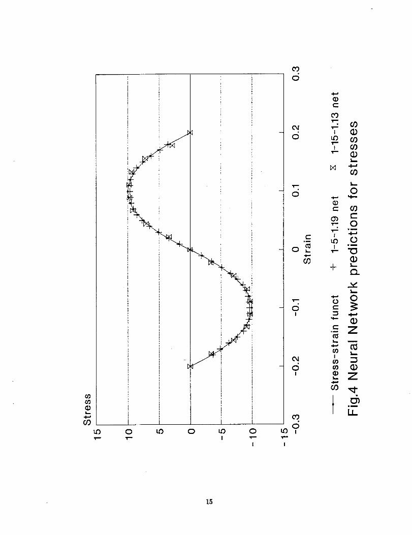
from cases 4 and 5 is plotted. Both cases are in good agreement with the known results. Fig-
ure 4 shows the comparison between cases 3 and 4. These two models are very close to the cho-sen stress-strain curve for the study. It is dit'ficult to select the best case from these plots.
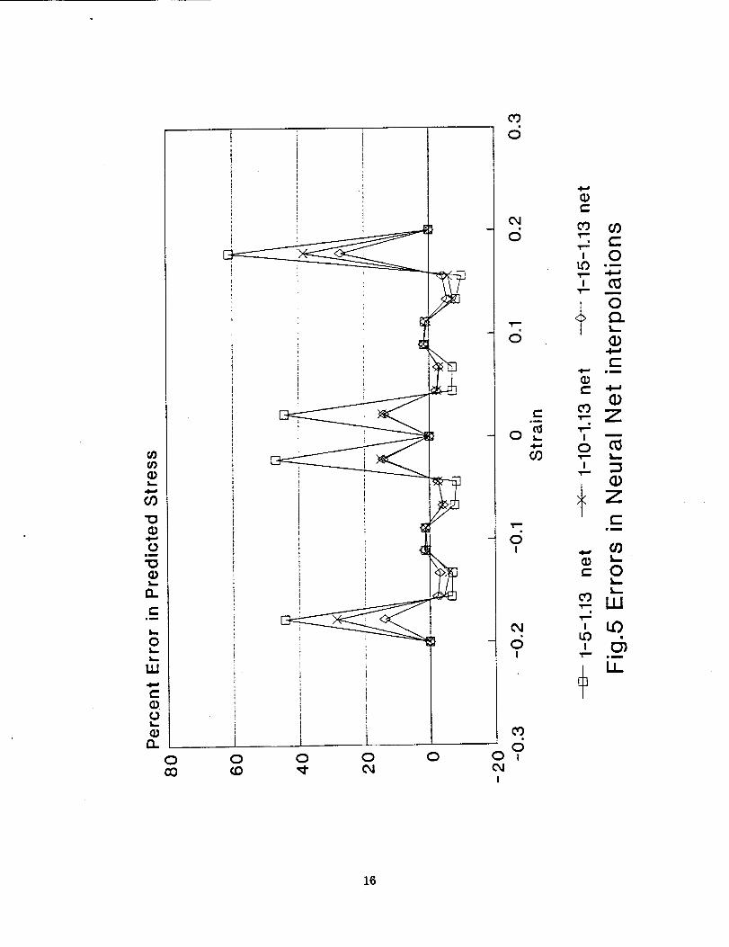
Therefore, for a closer look at the accuracy of the results, percent error in neural network inter-
polations versus strains are plotted on figures 5 to 7. It can be seen from these figures that the
percent error is within 5:3 percent when the strains used for training are also used for the predic-
tion of stresses. For other value of strains, these errors could be significant. Especially at

the two end points of the stress-strain curve where Strain values are nearly +0.2. However, in
nonlinear analysis, truss members do not attain these high values of strains. The other location
where errors in predictions are significant, is near the strain level zero. It should be noted thatat these strain levels the actual stress is approaching zero. Any small variation in the prediction
by Neural net causes a large relative percent error because in calculating the percent error, thedifference between the actual and the predicted stress is divided by a stress value which is smallin magnitude. This artificially magnifies the magnitude of the error. This shows that neural
network predictions although very accurate, could be in error at few points and a careful check-
ing is necessary before selecting an appropriate network configuration for materials modeling.
Figure 8 shows four truss geometries with dimensions and applied loading used in this
study. For all these trusses a uniform cross section area of 1 unit magnitude is assumed.Manual calculations are performed for Trussl and Truss2. The initial stiffness method is imple-
mented in a computer program written in C language to perform the nonlinear elastic truss
analysis. For both cases the nonlinear stress-strain function given by equation (2) is used.These results for load and load point displacements are plotted on figures 9 and 10. For both of
the trusses the results from the computer program and manual calculations are in close agree-ment. It shows that the initial stiffness method with incremental solution strategy can be used
for nonlinear analysis purposes, i. additlop to these calculations, further calculations are done
by dropping the nonlinear term from the equation (2). This results in a linear elastic material.The incremental solution leads to a straight line response for both of the trusses. This serves as
a further verification or the computer program. In addition to this, it can also be seen from fig-
ures 9 and 10 that there is significant nonlinearity in the responses of the trusses. The initialstiffness method has been able to capture this nonlinearity without any instability and errors.
The computer program was slightly modified to include functions alnit" and Upropagate2This allows to obtain the nonlinear stress-strain material data from the trained neural networks.
The Trussl is analyzed by this program for cases 1 to 5. For all calculations 10 load steps and a
tolerance of 0.005 are used. The results for applied load and load point displacements for all
these five case are shown on figures 11 and 12. Except for case 1 all other cases show fairly
good agreement with the manual calculations. It can be concluded from these figures that 1-5-1.i9
net produces the best results. It also leads to the conclusion that use of more input-output
pairs for training the network provide better accuracy. For this problem due to availability ofassumed stress-strain function any number of input-output pairs can be generated for network
training. However, most of the time the material data are available only at discrete points.
Therefore, computer program was slightly changed so that it can u86 material data supplied in
form of a table. This table was created Using the function given by the eciuation (2). For inter-
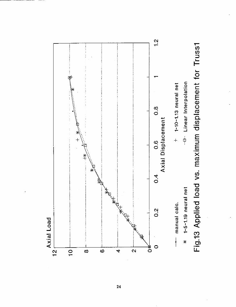
mediate points, a linear interpolation scheme was implemented in the computer program. Thiscase is indicated as linear interpolation on the plots. It more accurately emulates the existing
nonlinear analysis programs in which material data is provided at discrete points. The results
for cases 3 and 4 and from the linear interpolation scheme are shown on figure 13 for Trussl.
The results from case 4 and li_ear interpolation scheme are very close to exact results. Case 3
was chosen because it had the smallest maximum error of 0.0123 and rms error of 0.0057 among
all other cases after training the network. However these plots show that this network does not
produce the best results for Trussl. This particular network was trained for 23 604 cycles. It is
known that overtraining usually reduces the generalization capability of network models. Over-
all, all the models used, in the study provide adequate approximate solutions. It is encouragingthat the errors noted earlier seems to average out when neural nets are used for material mod-
eling. In situations where material data is available only at few points from experiments, neural
net approximations will be able to provide results within reasonable accuracy.

For Trussl a load of 9.6units is appliedin 10incrementswith a toleranceof 0.005. A timefunction is usedto evaluatethe total executiontime for all thefive cases.Theseresultsareshownon figure 14alongwith the casewhentheexactstress-strainfunctionis usedfor materialmodelingin the computerprogram. It canbeseenthat cases4 and5 take moretime whencom-paredwith thesimilar networksof cases2 and3, respectively,that haveidentical numberof hid-denunits. This differenceis dueto a highernumberof iterationsneededfor convergence.Thisalsopointsto a situation in whichthe bestneuralnet modelmaynot befastestalthoughit hasthesmallestnumberof hiddenunits.
Similar calculations are performed for Truss2 and shown on figure 15. Only cases 3 and 4
are used for neural net modeling. Once again the best results for applied load and load point
displacements are produced by case 4 when compared with the exact results from manual calcu-lations. For this truss the neural net model predicts better results than the linear interpolation
scheme. Figures 16 and 17 show the results for applied load and load point displacements forTruss3 and Truss4. For both cases it was not possible to perform a manual computation.
Therefore, the results from the initial stiffness program using the stress-strain function given by
equation (2), are considered as the exact solutions. They are also plotted on these figures forcomparison purposes. For both cases 1-5-1.19 net produces extremely accurate results.. They are
very close to the results from initial stiffness method. The linear interpolation scheme in bothcases fails to provide accurate solutions. In this study the stress-strain function used for
material response is a second order parabola. The linear interpolation scheme was not able to
approximate it closely. _or material behavior with sharper gradients than a parabola this
approximation scheme will further deteriorate. However, as mentioned earlier, this is the mostcommonly used scheme in the existing general purpose nonlinear'finite element analysis pro-
grams. These results show that it is prone to errors. It also shows that if neural network
modeling is used "carefully extremely accurate results can be obtained. Even in cases where themodel is not chosen carefully, results of reasonable accuracy are attainable. It is anticipated
that for materials with responses more complicated than a parabolic model, linear interpolation
scheme should lead to larger errors. In such cases neural network material modeling can effec-
tively be used in stress analysis problems.
To further investigate the convergence characteristics of all these schemes, maximum loadcalculations are done for all four trusses. For manual calculations maximum load is obtained by
choosing the peak points of the load-displacement plots. For initial stiffness method the peak
load is obtained by incrementing the applied loads till the solutions fail to converge. The
unloading part of the load displacement curve can not be calculated from this implementation ofinitial stiffness method due to incremental loading control. Table I shows that for first three
trusses, neural network is very close to exact maximum loads. The same can be interpreted
from figure 18. This is an indication that neural net material modeling does not appreciably
change the convergence characteristics of initial stiffness method.
The maximum displacements were calculated for applied load levels of 9.6, 20.5, 13.5,
and 12.8 for the trusses by all the suggested schemes. The numerical values are shown intable II and the results are on chart 19. Neural network models compare favorably With exact
solutions.
For the previous cases the total execution times are also obtained. They are listed in
table III. They are also shown on figure 20. For the first three trusses the time taken by the twoneural network models and the linear interpolation method are comparable. However, this trend
breaks down for the Truss4. In that case neural net provides accurate solutions but takes more
7

time to converge to the results as compared to the linear interpolation scheme. These are only a
few cases, and it is difficult to conclude on this basis that neural network material modeling willtake less computer time compared to other approaches. The time taken by the initial stiffness
method using the stress-strain function from equation (2) is the smallest. In this case the func-
tion evaluation is extremely fast because it is in a form of a simple equation. This indicates that
in nonlinear analysis most of the time is taken in obtaining the material response. For large size
nonlinear analysis problems, the choice of appropriate material modeling is very essential to keep
the analysis time within reasonable limits.
To further investigate the accuracy of neural net modeling with the other techniques, theforces in the members of the Truss3 are plotted on figures 21 to 24. The member numbering is
shown on figure 8. The applied load was increased in five steps to the maximum value of 13.5 units.It can be seen that all the techniques produce results very close to the exact solution with NN
models having a slight edge over the linear interpolation scheme.
CONCLUSIONS
From the results and the discussion the following conclusions can be drawn.
1. Neural network material modeling can successfully be implemented in a general purpose
analysis program.
2. The neural network models provide reasonably accurate solutions to the nonlinear elas-
tic analysis of trusses. If the network configuration is chosen with care extremely accurate
solutions are possible.
3. The network trained with larger input-output pairs reproduce the material behavior
more accurately.
4. The linear interpolation scheme for handling the material data is most commonly used
in general purpose nonlinear finite element analysis programs. The neural networks are able to
provide more accurate solutions in comparison to this scheme.
5. The incorporation of neural network material modeling in an analysis program does not
appreciably change the convergence characteristics of the initial stiffness method.
6. It is not possible to conclude from this study that neural net material modeling will
result in savings in computer time. It is comparable to the linear interpolation scheme.
7. It is anticipated that in case of more complicated material models neural network
approach will be able to provide more accurate results as compared to other schemes.
8. Neural network offers a viable alternative for material modeling. In this approach
material information can be captured in a small file containing weights and biases leading to sig-
nificant data base compression.
9. The network trained with least errors may not provide the most accurate solution to
the analysis problems.

10. More work is needed to establish guidelines for configuring an appropriate network
model. Especially in selecting ttle number of hidden processing elements. At this time it is
primarily a trial and error process.
REFERENCES
1. Sejnowski, T.J.; and Rosenberg, C.R.: NeTtalk: A Parallel Network That Learns to Read
Aloud. JHU/EECS-86101, Johns Hopkins Unversity, 1986.
2. Cottrell, G.W.; Munro, P.; and Zisper, D.: Image Compression by Back Propagation: An
Example of Extensional Programming. Institute for Cognitive Science, UCSD, La Jolla,
CA, 1987.
3. Lapedes, A.; and Farber, R.: Nonlinear Signal Processing (/sing Neural Networks:Prediction and System Modelling. LA-UR-87-2662, Los Alamos National Laboratory,
1987.
4. Hopfield, J.J.; and Tank, D.W.: Neural Computation of Decisions in Optimization Problems.
Biol. Cybern., voi. 52, no. 3, 1985, pp. 141-152.
5. Rumelhart, D.E.; Hinton, G.E.; and Williams, R.J.: Learning Internal Representations by
Error Propagation. Parallel Distributed Processing, Explorations in the Microstructure of
Cognition, D.E. Rumelhart and J.L. McCllelland, eds., MIT Press, Cambridge, Mass.,
1986, vol. 1, pp. 318-362.
6. Rehak, D.R.; Thewalt, C.R.; and Doo, L.B.: Neural Network Approaches in Structural
Mechanics Computations. Computer Utilization in Structural Engineering, J.K. Nelson Jr.,
ed., American Society of Civil Engineers, 1989, pp. 168-176.
7. Troudet, T.; and Merrill, W.: A Real Time Neural Net Estimator of Fatigue Life. NASA
TM-103117, 1990.
8. Berke, L.; and Hajela, P.: Applications of Artificial Neurai Networks in StructuralMechanics. NASA TM-102420, 1990, (Presented-Lecture Series on Shape and Layout
Optimization of Structural Systems, Int. Center for Mechanical Science, Italy, July 16-20,
1990, to be published by Springer-Verlag).
9. Alam, J.: Neural Network Paradigm and its Potential Applications in Structural Analysis.
Proceedings of Fourth International Conference on Computation in Civil and Building
Engineering, July 29-31, 1991, Tokyo, Japan.
10. Jain, I.D.; Mullen, R.L.; Bianchini, G.; and Berke, L.: On the use of Neural Networks forConstitutive Models, Submitted to ASCE Journal of Computing in Civil Engineering, 1990.
11. Ghaboussi, J.; Garrett, Jr., J.tI.; and Wu, X.: Material Modeling with Neural Networks.NUMETA 90: Numerical Methods in Engineering: Theory and Applications, G.N. Pande
and J. Middleton, eds., Elsevier, 1990.

12. Cook, R.D.: Concepts and Applications of Finite Element Analysis. Second Edition, John
Wiley & Sons, New York, 1981.
13. Owen, D.R.J.; and Hinton, E.: Finite Elements in Plasticity: Theory and Practice.
Pinerldge Press Limited, Swansea, U.K., 1980.
14. Baffes,P.T.: NETS User'sGuide. Software Technology Branch, NASA Lyndon B. Johnson
Space Center, Sept. 1989.
10

TABLE I.--PREDICTED MAXIMUM LOAD CAPACITY
OF TRUSSES
Truss number Trussl Truss2 Truss3 Truss4
Manual calculations 10.0 21.478 ..........
Stress-strain function 10.0 21.478 13.9 13.3
Neural 1-10-1.13 9.8 21.478 13.8 13.0
network1-5-1.19 9.6 21.478 13.5 12.8
Linear interpolation 10.0 20.5 13.8 13.3
TABLE II.--MAXIMUM DISPLACEMENTS FOR TRUSSES
Truss number Truss1 Truss2 Truss3 Truss4
Applied load 9.6 20.5 13.5 12.8
Stress-strain function 0.799 0.985 2.246 1.176
Neural 1-10-1.13 0.796 0.961 2.223 1.127
network1-5-1.19 0.928 1.104 2.444 1.202
Linear interpolation 0.799 1.085 2.335 1.244
TABLE III.--COMPUTER TIME FOR THE ANALYSIS OF
DIFFERENT TRUSSES
Truss number Truasl Truss2 Truss3 Truss4
Applied load 9.6 20.5 13.5 12.8
Stress-strain function 8.07 15.1 6.1 29.4
Neural 1-10-1.13 16.8 33.67 20.65 77.28
network1-5-1.19 25.58 42.18 35.32 113.15
Linear interpolation 12.52 37.56 13.13 55.75
11

12
IIm
.-I
o
,.,.J
¢-
°_
-r
_1
0.c
in
0
Zm
il
Z
0
t-O
gm
IL
0")Bm
gc_
r-
I-"
'T'--"
d_im
l.i_

_9
cO
U_T"
• I
o u_ o u_T-- I
i
oT"
!
U_T"
I
CDd
CJ
d
o
T"
,uI
U_!
T"
°-- -Jr-
O9
O9
L.
c 09
O'_ L.
_- OT-"
U_
!
_- c-O
wm
wm
"O(i)
Cl
7m
t_
Z
I C
Oc
CJ _- C
d _ co
_ 0
oI
13

IN
.Tin
i
iI
f
,Tin
CD
j I
LO OI 'Ira
I
¢0
d
- dI
¢0
o
I
.Tin
i CDd o _
Lm
N _
IL
o o
c_ c,- 0
¢D ,_ .,- .._
co _D
,r-" _d _- _
Ii m
_ LI
cDi_ Z
I "llm
I.l..
14
CO
to 0 to 0 toI
i0
I
cO
d
- dI
cO
0tO t
I
_)c-
cO
c_ _ 09
L_
N .4--,O9
L_
o o
o_ c-_- 0
•-_ _ 0(_ I .m
0 i- v- "0
c_
c_ _-
(_v__ m
IcJ _
ZL_
o3 _t
mu
LL
XG
CO
0
O.
im
L_
0L_
L_
iii
r-Qt_
13-
0CO
i
L!
J0t_
T
i ii I
0 0 0
cO
d
C_
d
-o
c-
t_- O _..
CO
-oI
C_
c5I
09i
00 :
I
e-
co 09
: 0
L.
C--•4_ gm
_zI i
c-
CO
_uJ
' t33eu
16

CD
09
"ID0
0wm
"0
0..
e"mm
k,..
0I,,.,.
I,.,..
e-CD0
Q.
0 cO 0I
O3
d
t-O
w_
0
• tn
0O_
I0
0!_- Z
t_
_ Z
¢--w_
_ LJ 0
W
ii
U_
17

0
0
0
"O
L_
n
OI
L__
0
ILl
0L_
ni
0cO o,I
!
i
004
Lf)
i
I
i
0T""
0I
O3
6
c5 .0
f-
o _
Z
o_ -_
Z
C
,° o
6I I.l-
cO0
0 i
I
18

l
10
• P
Truss1
]10
1_
--
10
1
i
z_l_
_- 10 _,: 10_
P
P
'_ 10 -,
Truss2
Truss3
Truss4
Fi9,8 ]}i _"£epen-l: ConFigurc_-t:ionoF T_'usses
19

"0
0,-,I
,m
X
0
21)

0_.1
Q..
1.0 0 _ 0 1.0 0
ai c_0000
LO
E
o'_d _o
oLI_
21

0..Jm
im
X
_<
[]
[]
[]
[]
[]
0 cO O0
• !
0
00oO
b-
L
0
cO
0
E
0
m
,m
X
_- 0
: E
Eii
X
E
_- o
E i
x wi
o
22

"0(1/0
--I
c_
X<
O,i
T--
T _CO
L_
e"
0L_
(D
t-O_
, F:o •T_
' 0
o N "_
0
d =i5 _" ×
•-_ _ E× u4
"0
o U_
23
0.-Jm
im
X,<
0 CO _ _ O_l 0
oJ
0')
I-
0
o oc _. c-
o EL_
® _ fl,)O0 r- -,-, 0
d .- m
0 o ¢_ CO
T- -.I0o E÷ c_
(0
,i wm
tn x
-_ tu
,<
c_
oJc_ 0
-- O_ t'l
E '
0 wm
24

0E
0
c _ I'--
0r- r-
to o_
! !
Z
m m
• • Z
tO O__-- T- t'-
• .... _° _ 01"- e-- I,,,.
'.- e'-
0
im
- 25

"0
0_.1
"0
,mm
Q.
!
t
iLO 0
O4
LO
CXl
r_
!._
I--
L_
0
o
-_ -s E
m
E 2 _ __) 1 "--
"a + c_ffl
'-'kS E
EE EX
"O
i.O _ O
O
E !,- I.D
lm
26

"0
0_1
"0(D
.ii
Q.
i I
, i t! .!
i i
i
I I i0_1 0 O0 _ _ 0_i 0
co O_
2I--
o
o
•_- _
27

[]
0.-I
¢.Iii
t_
,?.,,
[]
C_ 0 CO CO _ ¢_1 0
.q,.
CXl
o
_0oo , _ :_d_
_5 .f:=
,q,.
0_ _ 0o-- • "__ e-
d .__ _.
LI_
28

0..J
i=
Elu
X
i_o 0 _43
t-
O >.,03
im
0
, _-_
_ _ -__
@ ,,-
,_oo _ 0..___ -_ c_ _
29

J
!i!iiii!iiiiiiiiiiiiiiiiijiiiiiiiiiiiliiiiiiiii_
I_ I_Q.
iiiiiiiiiiii:ii_iiiili!iiiiii!i!!i!!iliiiiiiiiiii!i!iiiiilili!i!i!!iiiiiiiiii!i!._.
' !
i
!
_0
N--
iii!iiiiii_ii_iii_ii_iiiii!_ii!i!iiii!!!C_
..J
ii:!!-!!iii!_iiii!ili!ii!:!_iiiii_iiii_i:!!iii_ii!iii!_i::i,i:_i_::ii::i-liii_:iiiiiiiii_i:!.!:!i!_:!i!iiiiiii!ili!!!:ilL:i:_i¸ --,
, ! =======================================================
Eiiiiiii!iiii]ilEiiiii!iii_iiiiiiiiii!iiii!_!!!i_!i_
i U___
"- _ 0
0CO
• 0 (.0
i
o _ • .--
• - ...1
6
i
CO
ii
X"- _ _ CO 0I-- _ e-
_I I _ ._
_" I
o_1
"13
i
..1
6.
3O

lt
1
!
t
- i
0 0 0o4 0 00
e_
I'-
0 0 0 0_D _ oJ
• 0
0
0
co
t/) _-
0L
m
0
0E
m
em
0
E
t-O
0
om
"0
E0
O00
O0
0
0
wm
n00OJ
01im
Ll.
0..J
Q.Q.
31

!'-.
Ot._
OI.I,.,I_.
O
E
I'...
LO '_" 09 O_ '_ 0
! T ! r r !
................................. o.o... ................................................................
.4.I=l.
i !! }!!!i_7_:_::ii!i!!ii!!_iiii!_<
________________________________________________________________7_______________!.,_
i
i i '
_ iiiiiiiiiii_1iii_1i_1iiiiiiiiiiiiiiiilii1111!iiiiili!ii!iii i ," ............................................. '"-_°°'°°
] i, : iiiii)iiii:..................................................iiii!i! )!:.........................................! !ii!i_ '_
1_ i ! ! ! i
i_ i i _\\\\\\\\\\_1 _ _\\\\\\\\\\\\\\\\\\_'<:"i ! ...................................... •
! ! i iiiiiiii_ilili_!iiiiiiiii!iiiiiiiii_ilU_i' i!!!!i!iiii!liii_i_iiiiiiiiiiiiiiiiiii"l_i " 7 _ .-,I
i i i %,i:i,_iii:i_7:{Tii{;:i!i}_iT{_i_)i{iiii{i77'<::
i _ iiiiiiiiiiiiiiiiiii .i i ..................
I i " --{i77:[]i![]:77{:i77i!_[:iii{[:!:i,l_
i i E:i_i_77!_i:i_7%:i
t_ if) _" CO e_i _- O
e" .,..
oI..
cO e"m
I im_-- _J
l.I.
e" I--o_
o_
CO
l-
O
t-t_
OtnEOEt-
im
Oo
O
O
s_
09
O
tnEO
OT'--
O1gm
I,
o.J
t_t_
.J
32

0L_
0Ii
i_
cl
E
0
] p 1 _ 1
!!ii_ii!iiiiiii!iii!iiiiiHH!Hi!H!!!!!Hi!iiiiiiiHiiiiiiiiiiiii!iiiiiiiii_ii_ii_i_iiiiii;._._J
i_!i_ii!ii_iii!_i_i_iiiiiiiiiiiiiiiiiiiiiiiiiiiiiiii!iiii!iii_ii!!iii!!_!ii!iv-......................................................................,.°,.,,
filliilii!i!ii!ii!ili}i!ii!!_ <i i i
i
_ 0 _
!i!iiiiiiii!!!!!!!!!!!!!!!!!!!!!!!!!!!!!!!!!!!!!!!!!!!!!_!!_.
d._:_!:_ii_!_!i_:iiiii_i:i:i_!i_:_!_::_:!_i:iii:::_!_ii:_:!.i:i.::_)_i!i_i!i}iiiii!!_iii!i}!i:_::_;_.<
!
i __ _.iiiiiiiiiiiiiiiiiiiiiiiiiiiiiiiiiiii!ilito
_ i!$i!giii$i_iiiigiigigi$$!!_g_g!_ggigi_"1_
' I-: ili!!iii_:<
i _\\\\\\\\\\\\\\\__\\\\\\\\\\\\\\\_
i _: i
ii
ii_!iiiiiiiiiiiiiiii
i!iiiiiiiiiiii!iiiii"d
im
cD _ ¢_I O
oe- _..
m i
¢II O
e-
O
_J
¢II
O_
I.,. !
O9cOcO
O
O9
E
Ec-im
O
O
gi
Q.
oO
O_
ii
o_J
_J
33

C}O&,.
OU.
L..
.QEC)
cO (.C) _ c'q
- l 1 F
CO
0
i-6_J
O..,:c
0
iiiiiiiiiiiiiiiiiliiiiiiiiiiliiiiiiiiliiiii._J,4
: ili i:_'iil;:i::! i _*:<; i
: 'iii!iliiiiiiiiiiiliii' _6
[
,:_!ii".-'F"i!:_!!
i iiiiiiilii
. H'H.._,. _ ,,
• ____i!!iiiiiii!iii!i!!!iiii
_6%,i
..J6.
"O.J
<(
o
o
WW
m
-W
00 o)
Or)09
O
_t
E
E(-
ira
o
o
ii
c-
F-
coC_
mD
U.
"{3
O
(_.
c).<C
ii
._]
34

OL_
OU.
L_
.Q
EO
O
OT'-
CO _ ._- _ 0
i j i t 1
LO
C1I i!il !ii i i i!!ii!!!!!i!!iiiii!ii!!ii!!i!!i!i!_ii!i_iii!!_i!ii_!i!i,_!_i_i_!!i i <
liii!!!!!__i!i!iii!iiii__iiiiiiiiiiiii!i_____ii!iiiiiii!i!!!iiiiii___iii_jii!iiiii
__i_i_i_:_:_!:i!:_!i_!i!__!_:_!:!i_'i!i!!i!i_:_!i
O0
0
-d_J
Q..<
iiiiHi!i!!!!!!iiiiii!!!iiiiiiiiiiiiii!!iiiiiiiiiiiiiiiii
...... :..... k ....................i:: : <
--I
d
I
_ 0
<
b-
ai
-Jd.<
• Oc
_. O
T'-
Ov- c| o--v- .J
O _'_C
C_, --
L I
CO0o0o
L_
O
LO
L.
O
EOE
c"lu
OO
O
Omin
_Oc"
_tC_
im
LL
o.J
¢Icl<
_J
d<
35

Form ApprovedREPORT DOCUMENTATION PAGE OMBNo 0Z0_-0_88
PUOIIc rel_r_g buKlen to¢ t_s cotiecton of inlormatl0n m estimated to awlrage 1 hour Der rest)onN. 'inctu0mg the time tot" _ _. searcfltng ;x=s_ng =!,11 sources.
gathering and mairnaintng the dala needed, and completing and r_ the co_ection of infomta_. SecKI ¢ommecu regaling thill butOen e_zte Or any othe¢ aspect of th_
coilection of information, including suggestioas for reducing tt_s bu_en, t0 Washington He4KIClUartenl Serve'e=. Oitectoraw for information Ope_atJo_i an_ Repocl=. 1215 Jeffer,JOn
Davis Highway. Suite 1204. Adington. VA 22202-4302. and to the Office of Managemenl ,ln¢l Bu(Iget. Pil4:xlf'm0tk Reaudion Protect (0704-0188). Washinglo_. DC 20503.
1. AGENCY USE ONLY; (Leave blank) .... 2. REPORT DATE
November 1991
4. TITLE AND SUBTITLE
Application of Artificial Neural Networks
in Nonlinear Analysis of Trusses
6. AUTHOR(S)
J. Adam and L. Berke
'7"_" PERFORMING ORGANIZATION NAME(S) AND ADDRESS|ES)
National Aeronautics and Space Administration
Lewis Research Center
Cleveland, Ohio 44135-3191
9. SPONSORING/MONITORING AGENCY NAMES(S) AND ADDRESS(ES)
National Aeronautics and Space Administration
Washington, D.C. 20546-0001
11. SUPPLEMENTARY NOTES
t 3. REPORT TYPE AND DATES COVEREDTechnical Memorandum
S. FUNDING NUMBERS
WU-307-50-00
8. PER'FORMING ORGANIZATION
REPORT NUMBER
E-6676
10. SPONsoRINGIIdONITORINGAGENCY REPORT NUMBER
NASA TM-105319
J. Alam, Youngstown State University, Civil Engineering Department,-Youngstown, Ohio 44555; L. Berke, NASA
Lewis Research Center. Responsible person, L. Berke, (216) 433-3212.
12a. DISTRIBUJITIONIAVAILABIUT_ STATEMENT "
Unclassified - Unlimited
Subject Category 39
12b. DISTRIBUTION CODE
13. ABSTRACT (Maximum 200 words)
In the present study, a method is developed to incorporate neural network model based upon the Backpropagation
algorithm for material response into nonlinear elastic truss analysis using the initial stiffness method. Different
network configurations are developed to assess the accuracy of neural network modeling of nonlinear material
response. In addition to this, a scheme based upon linear interpolation for material data, is also implemented for
comparison purposes. It is found that neural network approach can yield very accurate results if used with care.
For the type of problems under consideration, it offers a viable alternative to other material modeling methods.
14. SUBJECT TERMS
Neural nets; Structural analysis; Material behavior; Back propagation; Material
modeling; Feedforward; Nonlinear analysis
17. SECURITY CLASSIFICATION 18. SECURITY CLASSIFICATION 19. SECURITY CLASSIFICATION
OF REPORT OF THIS PAGE OF ABSTRACT
Unclassified Unclassified Unclassified
15. NUMBER OF PAGES
3616. PRICE CODE
A0320- UMITATION OF ABSTRACT
NSN 7540-01-280-5500 StanclarO Form 298 (Rov. 2-89)Presc_b_a by ANSI Std. Z39-18


![Comparing nonlinear regression analysis and …Construc &ii Comparing nonlinear regression analysis and artificial neural networks [...]• M. A. Benbouras et al. 277 been mentioned](https://img.pdfslide.net/doc/110x75/5e62d9b36867275f530dc625/comparing-nonlinear-regression-analysis-and-construc-ii-comparing-nonlinear.jpg)