Embed Size (px)
Citation preview
1
ISABE-2015-20284
APPLICATION OF DISTRIBUTED PROPULSION CONCEPT ON DIFFERENT AIRCRAFT CONFIGURATIONS
Panos Laskaridis, Propulsion Engineering Centre, School of Aerospace, Transport and
Manufacturing, Cranfield University [email protected]
Bedfordshire, MK43 0AL, United Kingdom
Abstract
Distributed Propulsion is a novel concept that has the potential to improve aircraft design and performance. The paper provides a top level overview of how different airframe configuration can benefit from the adoption of distributed propulsion and how the architecture of the propulsion system and its associated components can be influenced by the design and operational requirements of the aircraft. The synergies considered include boundary layer ingestion, flap blowing, novel fuels, diverted propeller slipstreams, non-steady cycles and hybrid turbo electric power generation.
Nomenclature
BLI BWB CESTOL DP HALE HTS LNG OPR sfc SOFC TET TeDP
Boundary Layer Ingestion Blended Wing Body Cruise Efficient Short Take-Off and Landing Distributed Propulsion High Altitude Long Endurance High Temperature Superconductive Liquefied Natural Gas Overall Pressure Ratio Specific Fuel Consumption Solid Oxide Fuel Cells Turbine Entry Temperature Turbo Electric Distributed Propulsion
UAV Uninhabited Air Vehicle
Introduction
Global air transport is forecasted to grow by 4-5% year on year [1], [2]. The average fuel efficiency
benefit of developing advanced versions of tube and wing configurations amounts to 1-2% annually [3]. Therefore, the combined growth will outweigh any advancements leading to increased environmental impact. Although aircraft and engine manufactures achieved a lot in the last 50 years a lot more may be required to be done for the future.
One of the concepts that attracted a lot of interest in the last 15 years is that of Distributed Propulsion (DP). The exact benefits of the DP concept depend heavily on the airframe considered, the architecture of the propulsion system and the detailed installation. These issues are explored in the following sections of the paper.
Configurations
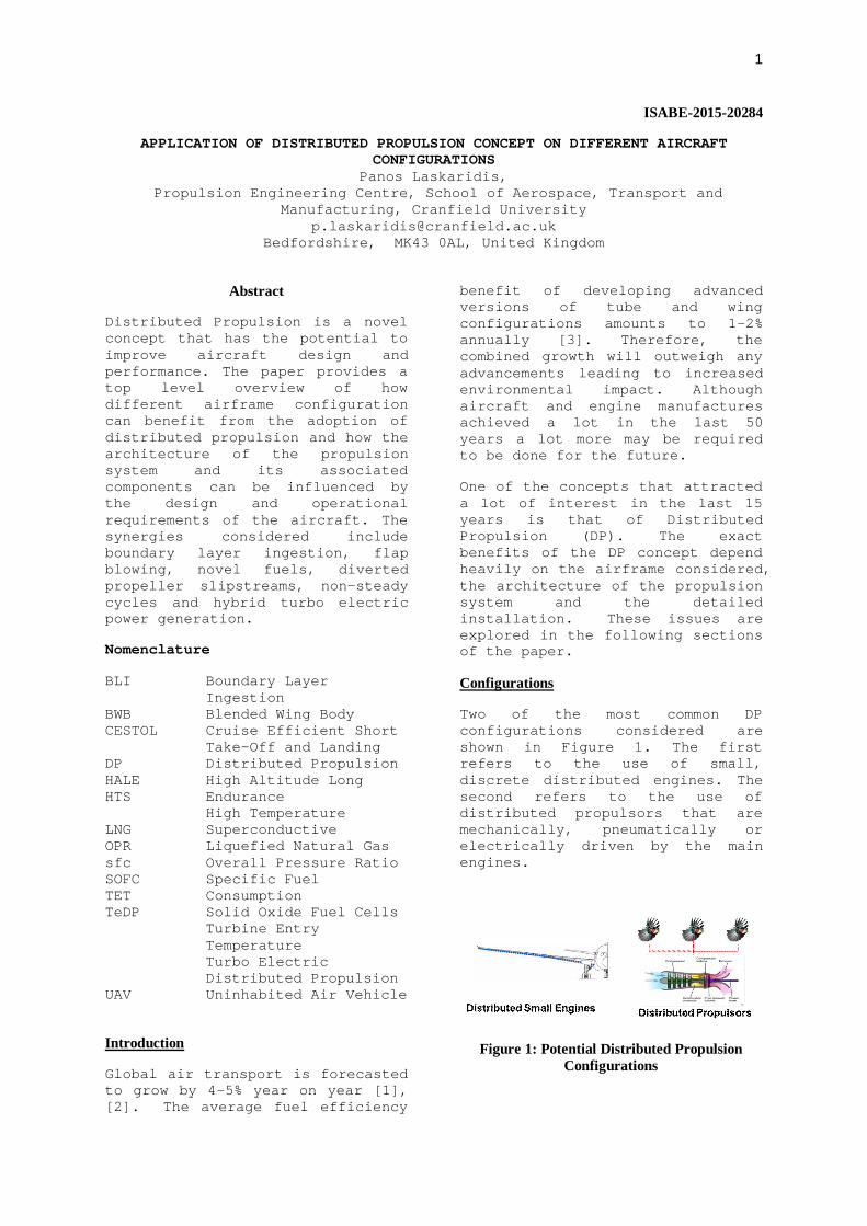
Two of the most common DP configurations considered are shown in Figure 1. The first refers to the use of small, discrete distributed engines. The second refers to the use of distributed propulsors that are mechanically, pneumatically or electrically driven by the main engines.
Figure 1: Potential Distributed Propulsion Configurations

2
Discrete engines can offer reductions in engine unit cost, improved wing structural design, increased propulsion system redundancy and enhanced flight control characteristics.
Additional benefits may be possible through airframe-propulsion aerodynamic synergies, to which Sehra and Whitlow [4] speculate possible fuel-burn reductions of up to 5%. However, feasibility studies of podded installations have indicated reductions in thermal efficiency due to scaling effects, as well as weight penalties due to necessary oversizing. Ameyugo et al. [5], for example, calculated SFC and weight penalties of 40% and 10% respectively, for a 10 podded turbofan engine propulsion system. Benefits from tighter propulsion-airframe integration have been investigated, with the Cruise Efficient Short Take-Off and Landing (CESTOL) concept [6].
Further challenges associated with the use of discrete engines may include maintenance reliability issues. Safety aspects related to uncontained failures, on the other hand, can be addressed by collectively optimising engine diameter, number of engines and distance between them. Maintenance reliability can also be addressed through the reduction of engine unit cost and the quick removal/replacement of a faulty engine to increase aircraft availability.
The most feasible, practical and flexible form of distributed propulsion is that which is comprised of multiple propulsors driven by common powerplants. The term “powerplant” represents any power supplying device, with the most probable being gas turbines, fuel cells and batteries or even a combination of these. The term “propulsors” refers to any device directly responsible for producing thrust, but may be extended to those influencing the aerodynamics of the aircraft to reduce drag and/or improve lift. Fans, open
rotors, propellers, compressors and ejector pumps can all be used as propulsors.
This type of distributed propulsion can drastically reduce specific thrust and offer additional benefits from airframe- aerodynamic synergies. Challenges relate to the transmission configuration, which adds weight, drag and inefficiencies to the overall system. Transmission systems may typically be mechanical (pneumatic or gears and shafts) or electrical [8],[9].
Pneumatic transmission, in this context, relates to the ducting of hot high pressure gases from a gas generator to drive a turbine-propulsor pair. Intuitively, these systems will suffer inefficiencies from duct losses. Additionally, the associated hazards require high-tensile piping with sufficient insulation for safety, thereby detracting from the seemingly lightweight potential of the concept. Recent studies have discounted pneumatic transmission [9]. An interesting concept for pneumatic transmission refers to the double pass tip driven fan discussed and assessed in [11] and [12] and shown in Figure 2.
Figure 2: Double Pass Tip Driven Fan [12]
Shaft and gear transmission systems are well-established and may be the most practical and feasible transmission candidate for near-term distributed propulsion systems. Challenges

3
exist in improving gearing efficiencies, developing lightweight materials and overcoming complexities in lubrication systems [9]. The Silent Aircraft BWB (SAX-40) developed at Cambridge, MIT and Cranfield [13, 14] and the NASA Boeing N2A HWB [15] are recent examples of distributed propulsion concepts favouring the use of mechanical gears and shafts.
Electrical power transmission is highly attractive due to the numerous degrees of freedom it offers. Of growing interest is Turbo-Electric Distributed Propulsion (TeDP). Benefits include:
ability to decouple the propulsors from the prime mover, improve the matching and efficiency of individual components (turbine and fan/propeller)
independently control the running line, rotational speed and thrust of the propulsors
installation flexibility and highly integrated airframe/propulsors designs.
Figure 3: Example of Mechanical Drive System [13]
The main challenges refer to increased mass penalties and transfer efficiency losses. The latter includes electrical and aerodynamic related losses (intake and component losses) when transmitting energy from the core
flow to the propulsors flow. Several variations of distributed propulsors configurations can exist including for example use of fuselage concentric propulsors.
Additional, but less popular configurations can also include cross flow fans and distributed exhausts. Tightly integrated cross-flow fan and wing arrangements offer augmented lift applications with high propulsive efficiencies from boundary layer flow control and span-wise distributed propulsion.
Distributed exhausts are another form of DP, where gases from a common gas generator are distributed across the aircraft to achieve different purposes. Typically, distributed exhausts are used for wake filling to reduce form drag, but may also serve the purpose of vectored thrust and flap blowing. However, the idea has generally lost popularity due to inefficiencies from duct and nozzle losses as well as the practicalities of piping hot gases through airframe structures. The concept however can be combined with the use of distributed propulsors to augment the aerodynamic and lift characteristics of the aircraft.
Distributed Propulsion Potential Synergies
Some of the main advantages of DP have already been mentioned in the previous sections of the paper. This section focuses on the collective benefits and the potential synergies between the airframe, the propulsion and the secondary power systems.
Propulsive efficiency: DP allows for a reduction in specific thrust which is not necessarily accompanied by an increase in the diameter of the engine. As a result, interference effects, drag and weight penalties as well as geometric constrains that limit today’s specific thrust and bypass ratio can be kept to a minimum through increased number

4
Figure 4: Inner & Outer Control Volumes
of fans. Further benefits can be realised by considering installations that allow for boundary layer ingestion (BLI). The different approaches are discussed in the following paragraph.
Boundary Layer Ingestion: Of the potential distributed propulsive synergies boundary layer ingestion has attracted the most attention. Ingesting the low momentum boundary layer offers benefits from a propulsive efficiency perspective. Alternatively, from drag perspective, the benefit may be viewed as a recovery of the profile drag by restoring uniformity to the airframe’s wake. Unfortunately, benefits are difficult to quantify because of the complex aerodynamic coupling between the airframe and propulsion system. Typically, boundary layer ingestion problems have been tackled using one of two control volume approaches. These are defined by Rodriguez [16] as outer and inner control volumes which encapsulate the entire aircraft or just the propulsion system, respectively.
Outer Control Volume Approaches: Early outer control volume investigations by Smith [17] used a simple actuator disk to model an ideal wake-ingesting propeller. The percentage improvement in propulsive efficiency relative to
a free-stream ingesting equivalent, was in the range of 5- 10%.
More recent and sophisticated outer control volume methods have been proposed by Drela [18] and Arntz et al. [19].
Internal Control Volume Approaches: The inner control volume approach allows for closer examination of boundary layer ingestion from a propulsion system perspective, and allows for closer examination of flow distortion on intake and fan performance. An internal control volume assessment was undertaken by Plas et al. [21] to analyse the possible performance benefits of boundary layer ingestion applied to the SAX-40 BWB concept [38], estimating benefits between 3-4%.
Intake pressure recovery losses due to flow distortion at the intake can be a significant concern. This issue has been extensively investigated by Rodriguez et al. [16], whose multidisciplinary optimisation methods predicts a fuel-burn benefit of around 7% for a BWB configuration with boundary layer ingestion versus a BWB ingesting free-stream flow.
Novel Airframe Configurations: Distributed propulsion can be used with novel aircraft configurations to enhance and further exploit potential synergies. BWB and hybrid configurations offer the possibility to increase the proportion of boundary layer ingested by the propulsors thus improving overall efficiency. Furthermore, such configurations can allow for embedded engines or over wing/fuselage installations to reduce noise. Finally, BWB configurations can be more volumetrically efficient than conventional tube & wing aircraft and as a result may be suitable for the use of novel cycles that require an increase in engine size. Such engines may include intercooled recuperated cycles or in the case of smaller aircraft use of combined gas turbine and unsteady cycles and/or hybrid gas turbine-fuel cell cycles.
5
Noise Reduction: DP can offer significant reductions in propulsion related noise through the synergies between the airframe and the propulsion system. Jet noise can be reduced through the reduction of jet velocity and specific thrust. Turbo-machinery and combustion induced noise can be further reduced by embedding the main engine into the fuselage or by using the airframe as a shield to divert the noise emitted from the intake or the exhaust sections.
Enhanced Aerodynamic & Flight Control Characteristics: DP can directly affect the aerodynamic characteristics of the whole aircraft. The exhaust jet or slipstream from the propulsors can be used to induce circulation through flap blowing. Directional control is also an option through thrust vectoring.
Improved propulsor control: Use of electrically driven propulsors allows independent control and operation of the core and the propulsors allowing optimum rotational speeds and component efficiencies. Control of the motors that are driving the propulsors can also be used to vary the thrust output of the propulsors either collectively (aircraft acceleration or deceleration) or separately to account for asymmetric power/thrust failures. Such a technique can also be used for yaw and roll control.
For a given power output, the rotational speed and torque of the motor can be controlled in conjunction with variable area propulsor nozzles to control the operating point/line of the propulsors. The selected schedule can be based on maximum thrust (for given power), maximum propulsor efficiency and/or improved stability/surge margin.
Alternatively the power output of the motor can be controlled along with the propulsor nozzle area or propeller pitch angle to split the total thrust output between the
propulsors and/or between the propulsors and the main engine.
The former can be used to augment aerodynamic and flight control characteristics while the latter can be used to increase overall propulsion performance though continuous optimisation of core, thermal and propulsive efficiency. For a given thrust output the thrust split and operating conditions of the propulsors and the main engine can be varied to control:
- TET, OPR and component efficiency (core efficiency)
- amount of BLI and power transmitted to propulsors (transfer efficiency)
- jet velocity (propulsive efficiency).
Smart or autonomous control systems can then be used to optimise the thrust split between the main engine and the propulsors at different phases of the mission profile or based on the specific requirements of a particular mission or even the condition of the various components to achieve a variable cycle engine and optimise one or more of the following:
1. Fuel consumption 2. Emissions 3. Hot section life consumption 4. Noise 5. Direct Operating Costs
Use of novel fuels: The volumetric efficiency of hybrid and BWB configurations can favour adoption of cryogenic fuels like hydrogen and methane. These can be used to cool the electrical system components while reducing losses and size. Hydrogen can also be used with hybrid cycles incorporating gas turbine and fuel cells, thus improving the overall efficiency of the propulsion system or its off-design characteristics and control. In such a case the fuel cell can be used as a preheater to the main combustion chamber and the electric output can be directly

6
fed into driving the distributed propulsors.
Novel cycles: In addition to the novel cycles mentioned above, hybrid cycles combining gas turbines and unsteady flow devices such as wave rotors and Otto cycles can also offer improved thermal efficiency and overall performance. Such option are attractive in the case of small engines where maximum TET and OPR are restricted by size effects and technology limits.
Turbo-Electric & Hybrid Propulsion: Turbo-Electric and Hybrid propulsion can offer a number of benefits such as hybrid fuel cell and gas turbine cycles mentioned above, improved component efficiency and control by decoupling the propulsors from the operation of the main engine as well as improved power management.
In the latter case batteries can be used in parallel to top up the power output of the gas turbine or in series to extend the range of the aircraft. In both cases the size of the engine can reduce and its design optimised for the conditions where the engine will operate for most of its life. Further advantages may include reduced and smoother engine transients. In such a case the dynamics of the system (load and gas turbine) can be easier to deal with through batteries to avoid the different response rates and resulting frequency lags of the various components. Batteries can be used directly to power small/brief transients allowing the engine to operate at constant power setting and therefore high values of core efficiency. In other cases they can be used to allow a smoother acceleration of the main engine.
In both cases the size of the main engine can reduce while elimination and/or reduction of transients can allow for reduced tip clearances and resulting leakages as well as improved life characteristics and reduction of thermal and mechanical loads
acting on the hot section of the engine. When the load required is too large for the use of batteries, the batteries can be used to accommodate the power transients resulting from the acceleration of the engine and protect the electrical system. In such a case the batteries will operate as accumulators and absorb the extra power delivered by the engine. To summarise, the electrical system can be designed to absorb the transients of the load or the power supply, ensure the integrity and safe operation of individual components and enhance efficiency.
Figure 5: Thrust Split and Effect of Transfer
Efficiency Distributed Propulsion Used With Different Aircraft Configurations & Mission Profiles
The exact benefits of DP depend heavily on the design and operational requirements of the aircraft in question. DP has the potential to directly affect the design and configuration of the aircraft along with its overall performance. Based on the synergies discussed in the previous sections of the paper, DP has a direct impact on the aerodynamics, weight, geometry and performance of the aircraft. Especially in the case of a TeDP, aircraft design can be viewed form an energy optimisation perspective. In such a case the three main aspects relate to minimising the energy requirements (drag and weight), improve the efficiency of producing energy, optimise energy management and storage (transfer
7
efficiency, batteries, hydrogen and power management).
At a top level, when considering the application of DP on different designs two main aircraft parameters become important: size and range. Aircraft size will affect power requirements and therefore the size of the DP system. Range on the other hand can be related to the requirement for high aerodynamic and propulsion efficiencies.
Large Long Range Aircraft
In the case of large long range aircraft aerodynamic and propulsion efficiency are usually a priority due to the long-time spent at cruise and the large amount of fuel required to complete the mission. The use of high bypass ratio engines with long range high capacity aircraft where efficiency is usually more important and the weight of the propulsion system becomes a smaller percentage of the fuel weight is a typical example of this practise.
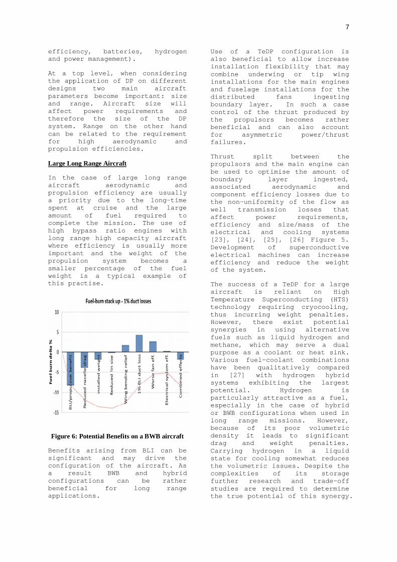
Figure 6: Potential Benefits on a BWB aircraft
Benefits arising from BLI can be significant and may drive the configuration of the aircraft. As a result BWB and hybrid configurations can be rather beneficial for long range applications.
Use of a TeDP configuration is also beneficial to allow increase installation flexibility that may combine underwing or tip wing installations for the main engines and fuselage installations for the distributed fans ingesting boundary layer. In such a case control of the thrust produced by the propulsors becomes rather beneficial and can also account for asymmetric power/thrust failures.
Thrust split between the propulsors and the main engine can be used to optimise the amount of boundary layer ingested, associated aerodynamic and component efficiency losses due to the non-uniformity of the flow as well transmission losses that affect power requirements, efficiency and size/mass of the electrical and cooling systems [23], [24], [25], [26] Figure 5. Development of superconductive electrical machines can increase efficiency and reduce the weight of the system.
The success of a TeDP for a large aircraft is reliant on High Temperature Superconducting (HTS) technology requiring cryocooling, thus incurring weight penalties. However, there exist potential synergies in using alternative fuels such as liquid hydrogen and methane, which may serve a dual purpose as a coolant or heat sink. Various fuel-coolant combinations have been qualitatively compared in [27] with hydrogen hybrid systems exhibiting the largest potential. Hydrogen is particularly attractive as a fuel, especially in the case of hybrid or BWB configurations when used in long range missions. However, because of its poor volumetric density it leads to significant drag and weight penalties. Carrying hydrogen in a liquid state for cooling somewhat reduces the volumetric issues. Despite the complexities of its storage further research and trade-off studies are required to determine the true potential of this synergy.

8
Due to the large power requirements of such an aircraft, use of batteries is likely to be limited to smoothing out engine transient operations rather than topping up the power output of the main propulsion system. Motors and generators are likely to be sized for an optimum thrust split at cruise to ensure a balance between transfer and propulsive efficiency as well as weight. The electrical system can then operate continually to this capacity to optimise utilisation. Variations in load and thrust requirements will then be covered by the main engine. As a result, thrust split will also vary along the mission, Figure 7.
The collective benefits of a super- conducted TeDP system used with a BWB configuration and a thrust split of 56% are shown in Figure 10. The aircraft considered had a capacity of 300 passengers and a range of 8000 nautical miles [25], [26].
Figure 7: Electric Power & Thrust Split Required By Propulsors During Mission Profile
The concept led to reductions in block fuel ranging from 5-10% relative to the use of underwing, free-stream ingesting, gas turbines with the actual value depending heavily on the pressure losses of the intake. In the case of a T&W configuration with the same mission requirements, use of 16 boundary layer ingesting fans distributed around the fuselage with a thrust split of 46%
resulted in 4% reduction in block fuel. In both cases the main benefits were attributed to reduced airframe drag due to BLI (around 7-10% reduction in fuel) coupled with reduced drag and mass of the main engines. In the case of the BWB the thrust split and power requirements of the distributed fans throughout the mission are shown in Figure 7. In both cases a hybrid fuel system has been considered with kerosene being the main fuel and hydrogen been used for cooling and also as fuel. The amount of hydrogen has been sized based on the cooling requirements of the electrical system.
The effect of having only hydrogen as fuel on the overall energy consumption has also been considered. A 40% thrust split was found to be close to the optimum. The hydrogen variant due to the increased volume was less efficient when compared to the pervious hybrid configuration.
Long Range BWB with Blown Flaps
In the case of a BWB, take off performance can be adversely affected when a static configuration is chosen due to the strong nose down pitching moment introduced when high lift devices are used. As a result, airframe rotation during take-off is achieved by deflecting the elevons (combination of elevators and ailerons) located at the back of the fuselage upwards. Such an action reduces the downward pitching moment along with the lift produced but also increases drag. In a configuration similar to the N3X aircraft [7], the exhaust jet of the distributed fans can be used to increase the effectiveness of the elevons and reduce the maximum deflection required for rotation and take-off, leading eventually to reduced drag and improved performance. The concept can also be used at cruise or other phases of the mission profile to trim the aircraft and reduce the associated trim drag.
9
Regional Aircraft
The short range of the aircraft makes it difficult to optimise the aircraft aerodynamics and engine design for maximum efficiency. Instead, operational flexibility and take-off performance combined with low capital costs become the main drivers in the design of such an aircraft. BLI is not very beneficial in such conditions due to the relatively low flying speeds and small surfaces but more importantly due to the fact that the aircraft will hardly spend any time at cruise.
Regional aircraft are usually characterised by relatively large wing areas and use of high lift devices that in many cases are combined with the installation of oversized propulsion systems that offer short take-off and landing performance. High bypass ratio, open rotors and turpoprop engines can all be suitable options for regional aircraft. The high thrust requirements of such designs coupled with the relatively short length of the aircraft result in oversized tails required to cater for engine failures and provide the ability to control the aircraft. On the other hand the technology and capital/development costs of such an aircraft must be kept to a minimum due to limited passenger capacity and the small profit margin that can be achieved from the airfare.
As a result turborops are often chosen to power such aircraft. The high propulsive efficiency at low flying speeds is often balancing out the low thermal efficiency of the turboprop. The low core or thermal efficiency is attributed to the use of modest OPR and TET.
The propellers can be electrically driven by one or more turbo-shaft engines. In such a case the slipstream of the propellers can be used to increase the lift of the wing. This is turn can be used to either improve the take-off performance or to reduce the size/weight of the wing. Further options include the increase in
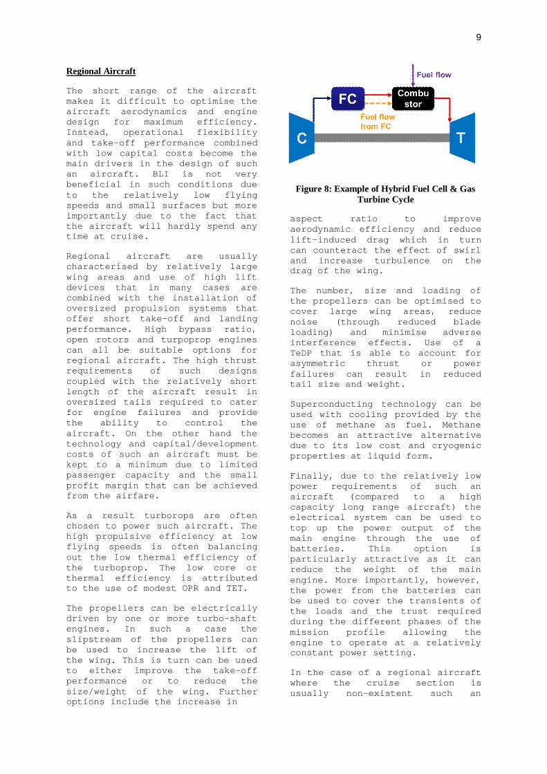
Figure 8: Example of Hybrid Fuel Cell & Gas Turbine Cycle
aspect ratio to improve aerodynamic efficiency and reduce lift-induced drag which in turn can counteract the effect of swirl and increase turbulence on the drag of the wing.
The number, size and loading of the propellers can be optimised to cover large wing areas, reduce noise (through reduced blade loading) and minimise adverse interference effects. Use of a TeDP that is able to account for asymmetric thrust or power failures can result in reduced tail size and weight.
Superconducting technology can be used with cooling provided by the use of methane as fuel. Methane becomes an attractive alternative due to its low cost and cryogenic properties at liquid form.
Finally, due to the relatively low power requirements of such an aircraft (compared to a high capacity long range aircraft) the electrical system can be used to top up the power output of the main engine through the use of batteries. This option is particularly attractive as it can reduce the weight of the main engine. More importantly, however, the power from the batteries can be used to cover the transients of the loads and the trust required during the different phases of the mission profile allowing the engine to operate at a relatively constant power setting.
In the case of a regional aircraft where the cruise section is usually non-existent such an

10
option can have a significant impact on engine efficiency and design. Overall engine efficiency could increase by avoiding transients that require extra energy input but also by minimising off-design operations that imply low component efficiencies. Engine life can also increase minimising maintenance costs through reduced thermal and mechanical fatigue damage.
HALE UAV
DP can offer significant benefits in the case of HALE UAVs. In fact such vehicles can act as technology platforms used to develop and mature some of the technologies required for commercial aircraft. Hydrogen is an attractive option for such aircraft due to the high energy content that becomes important when considering the long endurance requirements. Drag penalties associated with low density and increased tank size can be kept to a minimum due to the high altitude and low Mach number operation.
Gas turbines used with HALE aircraft operate at modest OPR and TET due to combination of low capital cost requirements and size constrains (i.e size of last stage of high pressure compressor).
On the other hand, due to the long endurance and the consumption of large amount of fuel that can account for 40-60% of the MTOW of the aircraft, thrust variations can be significant between the top of climb and the end of cruise leading to oversized engines with poor off-design characteristics.
The aerodynamic design of such aircraft is driven by high aspect ratio wings at the expense of weight. Finally, at cruise, the thrust power requirements can be comparable to the secondary power requirements for the operation of the electrical, communication and surveillance equipment. As a result relatively large amounts of electrical off-take power are required.
Hybrid cycles that combine fuel cells and gas turbines as shown in Figure 8 can be used to increase core efficiency and overcome the detrimental effect of size, modest pressure ratios and TET. The fuel cell option is particularly attractive since its output is electrical power and can be used to provide primary and secondary power. The fuel cell can also be used to improve off design performance by allowing it to operate at constant conditions and by controlling the power output of the main engine.
Alternately the core efficiency of the gas turbine can be increased by considering combining gas turbines and wave rotors or Otto cycles. While such engines tend to be heavier than gas turbines alone, the improved efficiency they can offer at low operating temperatures and pressures can outweigh the resulting mass penalties. As the size and OPT/TET of the engine increases these combined/hybrid cyces become less desirable when compared to high bypass ratio engines.
Distributed propellers can be used to increase the bending relief of the wing and allow a further increase in the aspect ratio improving aerodynamic efficiency. Alternatively, the slip stream of the propellers can be used to increase lift, reduce wing area and increase aspect ratio. Finally batteries can be used to operate in parallel or in series to the propulsion system and either extent range or reduce engine size. In the case of HALE UAVs, propulsors can also be used as Ram Air Turbines (RAT) to produce power and re-charge the batteries during descent. The flight profile of small UAVs can be optimised to that effect by continuously alternating between climb and glide.
Conclusions
Distributed propulsion has the potential to open up the design space of future aircraft and increase synergies between

11
airframe, propulsion and secondary power systems. The main advantage it has to offer is its flexibility and how it can be adapted to suit the design and operational requirements of different types of aircraft. DP can offer a paradigm shift in aircraft design where the propulsion system can have a direct effect on the design and configuration of the airframe. Although the paper focuses on the potential synergies and the application of DP on different airframes it must be recognised that significant technological challenges exist in all of the aspects considered that may prevent their application. As a result more detailed research is required to be able to quantify benefits, challenges, risks and enabling technologies.
References
[1] Airbus,Global Market Forecast 2011-2031, URL:www.airbus.com/company/market/forecast (Accessed 17 April 2015)
[2] The Boeing Company, Long Term Market, Current Market Outlook 2011-2030,URL www.boeing.com/commercial/cmo/ (Accessed 20 March 2015)
[3] IATA, A Global Approach to Reducing Aviation Emissions, First Stop: Carbon Neutral Growth From 2020, URL:www.iata.org (Accessed 25 March 2015)
[4] A. K. Sehra and W. Whitlow Jr. Propulsion and Power for 21st Century Aviation. Progress in Aerospace Sciences, (40):199 – 235, 2004.
[5] G. Ameyugo, M. Taylor, and R. Singh. Distributed Propulsion Feasibility Studies. In 25th International Congress of the Aeronautical Sciences, 2006.
[6] H. D. Kim, J. J. Berton, and S. M. Jones. Low Noise Cruise Efficient Short Take-Off and Landing Transport Vehicle Study. In 6th AIAA Aviation Technology, Integration and Operations Conference (ATIO), number AIAA 2006-7738, Wichita, Kansas, 25-27 September 2006. AIAA.
[7] H. D. Kim, G. V. Brown, and J. L. Felder. Distributed Turboelectric Propulsion for Hybrid Wing Body Aircraft. In 9th International Powered Lift Conference, United Kingdom, July 2008.
[8] H. D. Kim. Distributed Propulsion Vehicles. In 27th International Congress of the Aeronautical Sciences, 2010.
[9] A. Isyanov, A. Lukovnikov, and A. Mirzoyan. Development Challenges of Distributive Propulsion System for Advanced Aeroplanes. Aircraft Engineering and Aerospace Technology: An International Journal, 86(6):459–463, 2014.
[10] B. R. Winborn, Jr. ADAM III V/STOL concept. Journal of Aircraft, 7(2):175 – 181, 1970.
[11] H. Casado, E. Cristobal, A. Lorido and K. W. Ramsden, A Tip-Turbine Driven Propulsion Fan Concept, GT2002-30651, pp. 877-885Volume 2: Turbo Expo 2002, Parts A and B, Amsterdam, The Netherlands, June 3–6, 2002
[12] G. Doulgeris, Modelling and Integration of Advanced Propulsion Systems, PhD Thesis, Cranfield University, March 2008
[13] C. A. Hall and D. Crichton. Engine And Installation Configurations For A Silent Aircraft. In International Society for Air Breathing Engines, number ISABE-2005-1164. American Institute of Aeronautics and Astronautics, Inc., 2005.
[14] E. de la Rosa Blanco, C.A. Hall, and D.Crichton. Challenges in the Silent Aircraft Engine Design. In 45th AIAA Aerospace Sciences Meeting and Exhibit, number AIAA 2007-454, Reno, Navada, January 2007. American Institute of Aeronautics and Astronautics, Inc.
[15] M. T. Tong, S. M. Jones, W. J. Haller, and R. F. Handschuh. Engine Conceptual Design Studies for a Hybrid Wing Body Aircraft. Technical Memorandum NASA/TM—2009-215680, NASA, 2009.

12
[16] D. L. Rodriguez. A Multidisciplinary Optimization Method for Designing Boundary Layer Ingestion Inlets. PhD thesis, Department of Aeronautics and Astronautics, Stanford University, January 2001.
[17] L. Jr Smith. Wake Ingestion Propulsion Benefit. In AIAA/SAE/ASME/ASEE 27 th Joint Propulsion Conference, 1991.
[18] M. Drela. Power Balance in Aerodynamic Flows. AIAA Journal, 47(7):1761 – 1771, 2009.
[19] A. Arntz, O. Atinault, and A. Merlen. Exergy-Based Formulation for Aircraft Aeropropulsive Performance Assessment: Theoretical Development. AIAA Journal, 2014.
[20] S. A. Pandya, A. Huang, A. Espitia, and A. Uranga. Computational Assessment of the Boundary Layer Ingesting Nacelle Design of the D8 Aircraft. In AIAA SciTech 52nd Aerospace Sciences Meeting, number AIAA 2014-0907, National Harbour, Maryland, January 201
[21] A. P. Plas, M. A. Sargeant, V. Madani, D. Crichton, E. M. Greitzer, T. P. Hynes, and C. A. Hall. Performance of a Boundary Layer Ingesting (BLI) Propulsion System. American Institute of Aeronautics and Astronautics, Paper AIAA 2007-450, 2007
[22] F. Berg, J. Palmer, P. Miller, M. Husband, and G Dodds. HTS Electrical System for a Distributed Propulsion Aircraft. IEEE Transactions on Applied Superconductivity, 25(3), June 2015.
[23] Liu C., Laskaridis P. and Singh R. A preliminary method to estimate impact of inlet flow distortion on boundary layer ingesting propulsion system design point performance, Proceedings of the Institution of Mechanical Engineers Part G-Journal of Aerospace Engineering, August 1, 2013,doi: 10.1177/0954410013496750
[24] Liu C, Doulgeris G, Laskaridis P & Singh Thermal cycle analysis of turboelectric
distributed propulsion system with boundary layer ingestion, Aerospace Science and Technology, 27 (1) 163-170
[25] P. Laskaridis , V. Pachidis , P. Pilidis , (2014) "Opportunities and challenges for distributed propulsion and boundary layer ingestion", Aircraft Engineering and Aerospace Technology: An International Journal, Vol. 86 Iss: 6, pp.451 – 458
[26] E. Valencia, D. Nalianda, P. Laskaridis, R. Singh, Methodology to assess the performance of an aircraft concept with distributed propulsion and boundary layer ingestion using a parametric approach, Proceedings of the Institution of Mechanical Engineers, Part G: Journal of Aerospace Engineering, March 2015 vol. 229 no. 4 682-693
[27] Rudi Kirner, An Investigation of Distributed Propulsion on Advanced Aircraft Configurations, PhD Thesis, Cranfield University, Cranfield, 2013
[28] A. Rolt, R. Kirner, P. Laskaridis, L. Raffaelli, Analysis of Distributed Propulsion on Advanced Vision 20 Aircraft Concepts XXI International Symposium on Air Breathing Engines (ISABE 2013), Busan, South Korea, 2013.
[29] J. L. Felder, H. Dae Kim, and G. V. Brown. Turboelectric Distributed Propulsion Engine Cycle Analysis for Hybrid-Wing-Body Aircraft. In 47th AIAA Aerospace Sciences Meeting Including The New Horizons Forum and Aerospace Exposition, number AIAA 2009-1132, Orlando, Florida, January 2009. American Institute of Aeronautics and Astronautics.