Embed Size (px)
Citation preview
IJSTE - International Journal of Science Technology & Engineering | Volume 1 | Issue 11 | May 2015 ISSN (online): 2349-784X
All rights reserved by www.ijste.org
83
Application of Forces Acting on Jetty Structure
Himesh B. Chopra Prof. P.G. Patel
P.G. Student Professor
Department of Applied Mechanics Department of Applied Mechanics
L. D. College of Engineering, Ahmedabad-380015 L. D. College of Engineering, Ahmedabad-380015
Abstract
Jetties are lifeline structures as they provide a cost effective method for transporting large quantities of goods and raw materials.
Jetty structures are generally located in deep sea. Generally structures are subjected to dead load, live load, wind load,
earthquake load and temperature load while Jetties are subjected to additional marine loads like current load, wave load, berthing
load and mooring load. This additional forces are complex in nature and hence the understanding of the forces is of importance.
This paper is focused towards the calculation of various forces acting on jetty structure and its application to the model for
analysis.
Keywords: Jetty, Berthing, Mooring, Fixity Calculation, Fender System
________________________________________________________________________________________________________
I. INTRODUCTION
Harbours and jetties are lifeline structures as they provide a cost effective method for transporting large quantities of goods and
raw materials into and out of a region. These structures also play a significant role in the transportation system in terms of
evacuation of people before or after natural disasters, e.g. earthquakes and tsunamis.
Generally berthing jetties are constructed away from the shoreline inside the sea to get sufficient water depth for anchorage of
ships. These are connected to the shore by approach jetties supported by piles, which generally are embedded in the sloping
ground. Jetties are built parallel to the navigation channel, which is usually perpendicular to the shore. The jetty head should
normally be aligned so that the vessel is berthed in the direction of the strongest currents.
Jetty structures are generally located in deep sea. To achieve this depth and to have an economic structure, it is prefer to have
pile supported structure. Structure becomes flexible with significant amount of lateral loads, so care should be taken by designer
to select type pile and accommodate pile arrangement in such a way that structure become safe to utilize the berth. In India,
Bored cast in situ pile are commonly used where berth are located near shore. Bored cast in situ piles are suitable for use to
achieve large load bearing capacities by means of the large shaft diameters.
II. CLASSIFICATION OF LOADS
The various loads acting on the berthing structures are classified as:
Loads from Seaside A.
The loads from the sea side include the horizontal forces caused by waves, the forces caused by berthing and vessel’s pull from
bollard. The forces caused by berthing of vessels are determined from the velocity and angle of approach of the vessels.
Loads from Deck B.
The important loads from the deck are the vertical loads caused by self weight of the deck, superimposed loads from handling
equipments. Horizontal loads are mostly due to wind forces on structures and also due to the breaking force of cranes if
applicable.
Loads from Landside C.
Horizontal loads are caused from landside due to the earth pressures and differential water pressure. Vertical loads are caused by
the weight of filling and superimposed load on filling.
III. MODELLING DATA
For the site location at Mundra, properties of various soil layers has shown below in fig. (1)

Application of Forces Acting on Jetty Structure (IJSTE/ Volume 1 / Issue 11 / 016)
All rights reserved by www.ijste.org
84
Fig. 1: Details of Soil Strata at Mundra
On the basis of Length of vessel, Size of Jetty is fixed, as shown below in table (1) Table - 1
Details of Vessel
The provided c/c distance between longitudinal pile is 7m and c/c distance between transverse pile is 8m. After number of trial
and error, Size of longitudinal beams are fixed as 1.2m width and 2m depth while size of transverse beams are fixed as 1.4m
width and 2.2m depth. To avoid congestion of reinforcement, appropriate difference in depth between longitudinal and
transverse beams are provided. Diameter of bored cast-in-situ concrete pile is fixed as 1.2m. Depth of pile is fixed on basis of
fixity calculation. So calculated depth of pile is 39m. After analysis Capacity of piles are checked at fixity level. If the calculated
capacity of pile is observed to be lesser than axial force at fixity level then the depth of piles should be increased.
Application of Forces Acting on Jetty Structure (IJSTE/ Volume 1 / Issue 11 / 016)
All rights reserved by www.ijste.org
85
IV. LOADS ON BERTHING STRUCTURES
Dead Load: A.
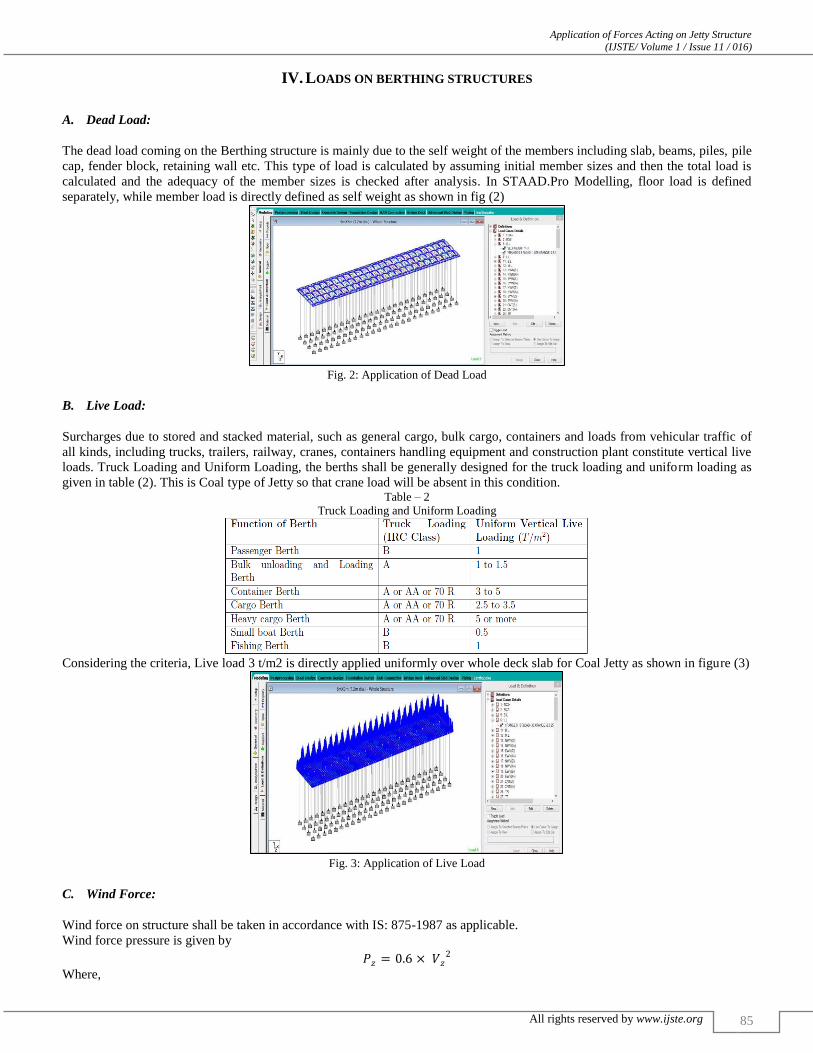
The dead load coming on the Berthing structure is mainly due to the self weight of the members including slab, beams, piles, pile
cap, fender block, retaining wall etc. This type of load is calculated by assuming initial member sizes and then the total load is
calculated and the adequacy of the member sizes is checked after analysis. In STAAD.Pro Modelling, floor load is defined
separately, while member load is directly defined as self weight as shown in fig (2)
Fig. 2: Application of Dead Load
Live Load: B.
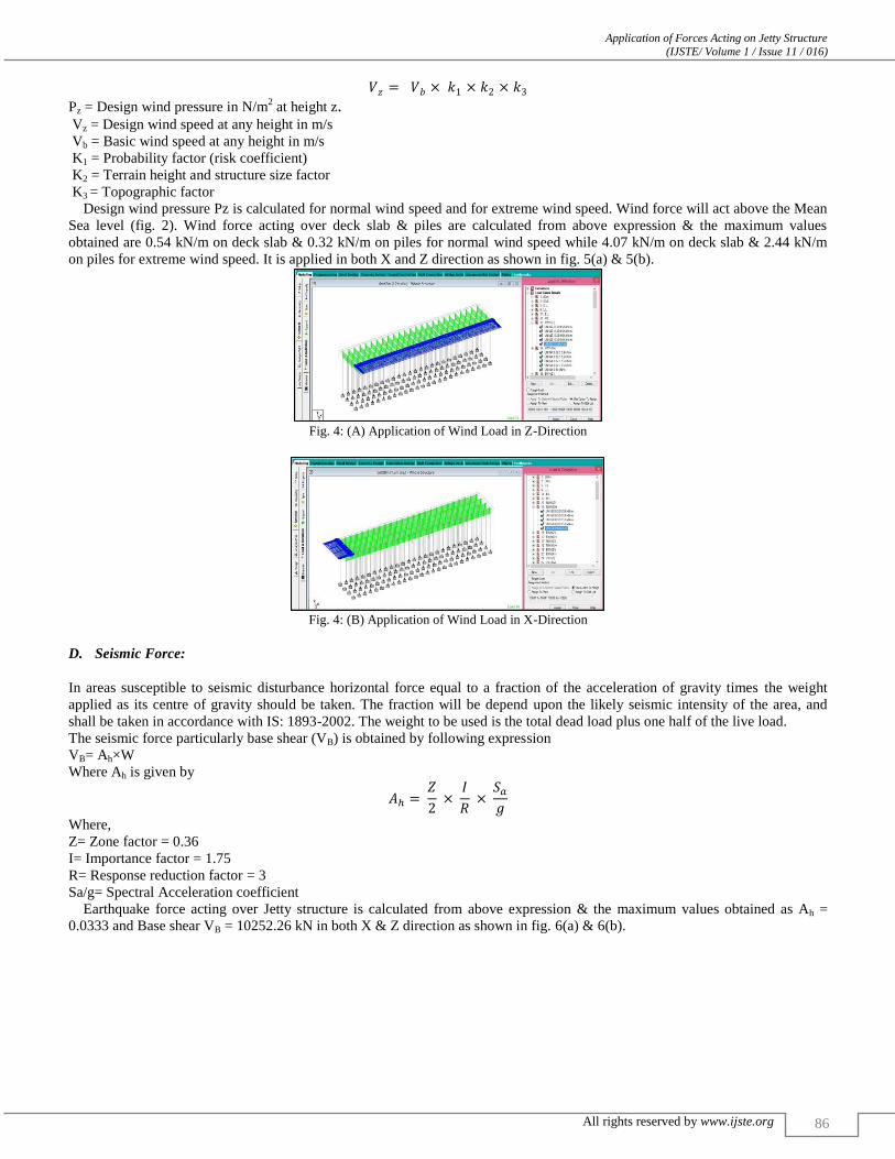
Surcharges due to stored and stacked material, such as general cargo, bulk cargo, containers and loads from vehicular traffic of
all kinds, including trucks, trailers, railway, cranes, containers handling equipment and construction plant constitute vertical live
loads. Truck Loading and Uniform Loading, the berths shall be generally designed for the truck loading and uniform loading as
given in table (2). This is Coal type of Jetty so that crane load will be absent in this condition. Table – 2
Truck Loading and Uniform Loading
Considering the criteria, Live load 3 t/m2 is directly applied uniformly over whole deck slab for Coal Jetty as shown in figure (3)
Fig. 3: Application of Live Load
Wind Force: C.
Wind force on structure shall be taken in accordance with IS: 875-1987 as applicable.
Wind force pressure is given by
Where,
Application of Forces Acting on Jetty Structure (IJSTE/ Volume 1 / Issue 11 / 016)
All rights reserved by www.ijste.org
86
Pz = Design wind pressure in N/m2 at height z.
Vz = Design wind speed at any height in m/s
Vb = Basic wind speed at any height in m/s
K1 = Probability factor (risk coefficient)
K2 = Terrain height and structure size factor
K3 = Topographic factor
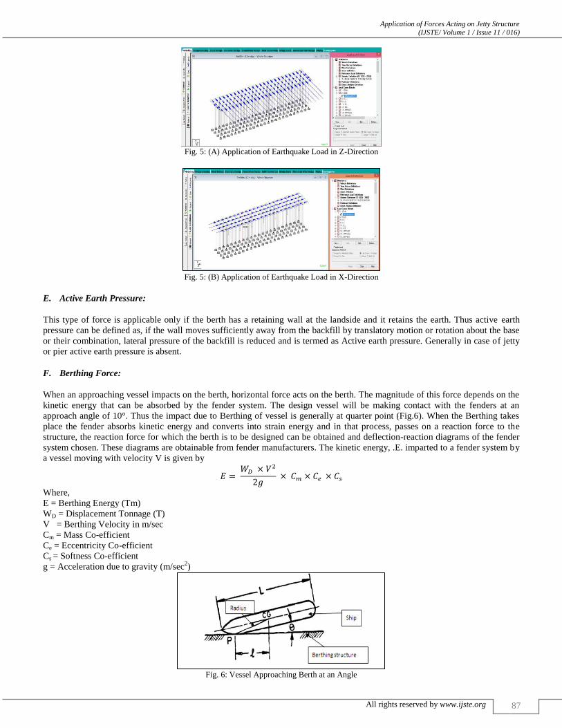
Design wind pressure Pz is calculated for normal wind speed and for extreme wind speed. Wind force will act above the Mean
Sea level (fig. 2). Wind force acting over deck slab & piles are calculated from above expression & the maximum values
obtained are 0.54 kN/m on deck slab & 0.32 kN/m on piles for normal wind speed while 4.07 kN/m on deck slab & 2.44 kN/m
on piles for extreme wind speed. It is applied in both X and Z direction as shown in fig. 5(a) & 5(b).
Fig. 4: (A) Application of Wind Load in Z-Direction
Fig. 4: (B) Application of Wind Load in X-Direction
Seismic Force: D.
In areas susceptible to seismic disturbance horizontal force equal to a fraction of the acceleration of gravity times the weight
applied as its centre of gravity should be taken. The fraction will be depend upon the likely seismic intensity of the area, and
shall be taken in accordance with IS: 1893-2002. The weight to be used is the total dead load plus one half of the live load.
The seismic force particularly base shear (VB) is obtained by following expression
VB= Ah×W
Where Ah is given by
Where,
Z= Zone factor = 0.36
I= Importance factor = 1.75
R= Response reduction factor = 3
Sa/g= Spectral Acceleration coefficient
Earthquake force acting over Jetty structure is calculated from above expression & the maximum values obtained as Ah =
0.0333 and Base shear VB = 10252.26 kN in both X & Z direction as shown in fig. 6(a) & 6(b).
Application of Forces Acting on Jetty Structure (IJSTE/ Volume 1 / Issue 11 / 016)
All rights reserved by www.ijste.org
87
Fig. 5: (A) Application of Earthquake Load in Z-Direction
Fig. 5: (B) Application of Earthquake Load in X-Direction
Active Earth Pressure: E.
This type of force is applicable only if the berth has a retaining wall at the landside and it retains the earth. Thus active earth
pressure can be defined as, if the wall moves sufficiently away from the backfill by translatory motion or rotation about the base
or their combination, lateral pressure of the backfill is reduced and is termed as Active earth pressure. Generally in case of jetty
or pier active earth pressure is absent.
Berthing Force: F.
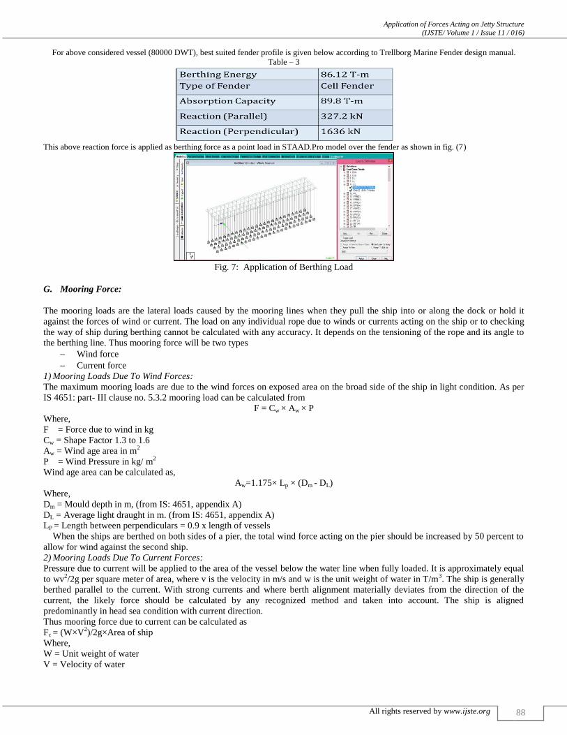
When an approaching vessel impacts on the berth, horizontal force acts on the berth. The magnitude of this force depends on the
kinetic energy that can be absorbed by the fender system. The design vessel will be making contact with the fenders at an
approach angle of 10°. Thus the impact due to Berthing of vessel is generally at quarter point (Fig.6). When the Berthing takes
place the fender absorbs kinetic energy and converts into strain energy and in that process, passes on a reaction force to the
structure, the reaction force for which the berth is to be designed can be obtained and deflection-reaction diagrams of the fender
system chosen. These diagrams are obtainable from fender manufacturers. The kinetic energy, .E. imparted to a fender system by
a vessel moving with velocity V is given by
Where,
E = Berthing Energy (Tm)
WD = Displacement Tonnage (T)
V = Berthing Velocity in m/sec
Cm = Mass Co-efficient
Ce = Eccentricity Co-efficient
Cs = Softness Co-efficient
g = Acceleration due to gravity (m/sec2)
Fig. 6: Vessel Approaching Berth at an Angle
Application of Forces Acting on Jetty Structure (IJSTE/ Volume 1 / Issue 11 / 016)
All rights reserved by www.ijste.org
88
For above considered vessel (80000 DWT), best suited fender profile is given below according to Trellborg Marine Fender design manual.
Table – 3
This above reaction force is applied as berthing force as a point load in STAAD.Pro model over the fender as shown in fig. (7)
Fig. 7: Application of Berthing Load
Mooring Force: G.
The mooring loads are the lateral loads caused by the mooring lines when they pull the ship into or along the dock or hold it
against the forces of wind or current. The load on any individual rope due to winds or currents acting on the ship or to checking
the way of ship during berthing cannot be calculated with any accuracy. It depends on the tensioning of the rope and its angle to
the berthing line. Thus mooring force will be two types
Wind force
Current force
Mooring Loads Due To Wind Forces: 1)
The maximum mooring loads are due to the wind forces on exposed area on the broad side of the ship in light condition. As per
IS 4651: part- III clause no. 5.3.2 mooring load can be calculated from
F = Cw × Aw × P
Where,
F = Force due to wind in kg
Cw = Shape Factor 1.3 to 1.6
Aw = Wind age area in m2
P = Wind Pressure in kg/ m2
Wind age area can be calculated as,
Aw=1.175× Lp × (Dm - DL)
Where,
Dm = Mould depth in m, (from IS: 4651, appendix A)
DL = Average light draught in m. (from IS: 4651, appendix A)
LP = Length between perpendiculars = 0.9 x length of vessels
When the ships are berthed on both sides of a pier, the total wind force acting on the pier should be increased by 50 percent to
allow for wind against the second ship.
Mooring Loads Due To Current Forces: 2)
Pressure due to current will be applied to the area of the vessel below the water line when fully loaded. It is approximately equal
to wv2/2g per square meter of area, where v is the velocity in m/s and w is the unit weight of water in T/m
3. The ship is generally
berthed parallel to the current. With strong currents and where berth alignment materially deviates from the direction of the
current, the likely force should be calculated by any recognized method and taken into account. The ship is aligned
predominantly in head sea condition with current direction.
Thus mooring force due to current can be calculated as
Fc = (W×V2)/2g×Area of ship
Where,
W = Unit weight of water
V = Velocity of water
Application of Forces Acting on Jetty Structure (IJSTE/ Volume 1 / Issue 11 / 016)
All rights reserved by www.ijste.org
89
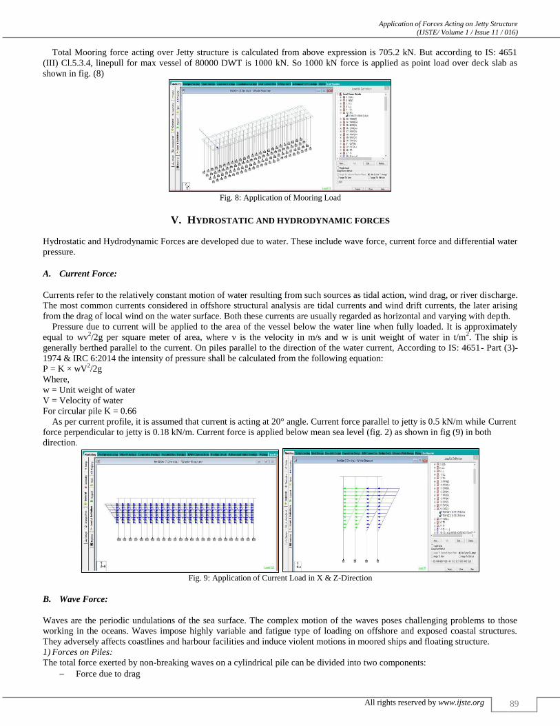
Total Mooring force acting over Jetty structure is calculated from above expression is 705.2 kN. But according to IS: 4651
(III) Cl.5.3.4, linepull for max vessel of 80000 DWT is 1000 kN. So 1000 kN force is applied as point load over deck slab as
shown in fig. (8)
Fig. 8: Application of Mooring Load
V. HYDROSTATIC AND HYDRODYNAMIC FORCES
Hydrostatic and Hydrodynamic Forces are developed due to water. These include wave force, current force and differential water
pressure.
Current Force: A.
Currents refer to the relatively constant motion of water resulting from such sources as tidal action, wind drag, or river discharge.
The most common currents considered in offshore structural analysis are tidal currents and wind drift currents, the later arising
from the drag of local wind on the water surface. Both these currents are usually regarded as horizontal and varying with depth.
Pressure due to current will be applied to the area of the vessel below the water line when fully loaded. It is approximately
equal to wv2/2g per square meter of area, where v is the velocity in m/s and w is unit weight of water in t/m
2. The ship is
generally berthed parallel to the current. On piles parallel to the direction of the water current, According to IS: 4651- Part (3)-
1974 & IRC 6:2014 the intensity of pressure shall be calculated from the following equation:
P = K × wV2/2g
Where,
w = Unit weight of water
V = Velocity of water
For circular pile K = 0.66
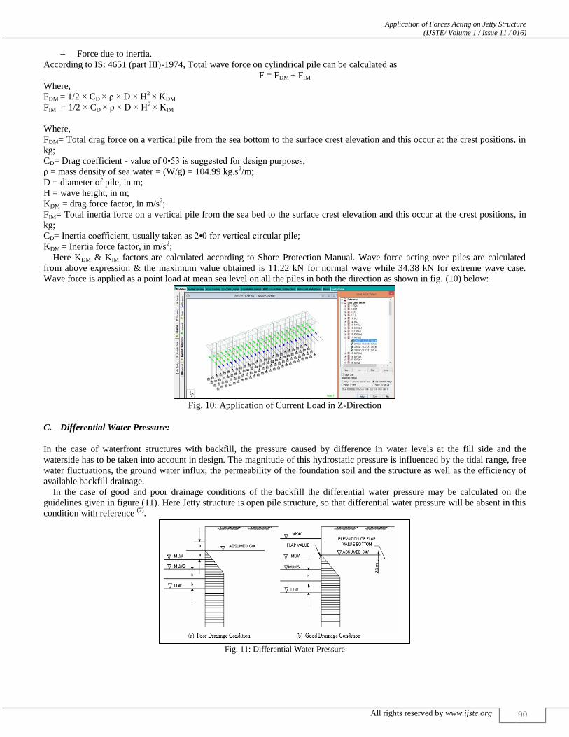
As per current profile, it is assumed that current is acting at 20° angle. Current force parallel to jetty is 0.5 kN/m while Current
force perpendicular to jetty is 0.18 kN/m. Current force is applied below mean sea level (fig. 2) as shown in fig (9) in both
direction.
Fig. 9: Application of Current Load in X & Z-Direction
Wave Force: B.
Waves are the periodic undulations of the sea surface. The complex motion of the waves poses challenging problems to those
working in the oceans. Waves impose highly variable and fatigue type of loading on offshore and exposed coastal structures.
They adversely affects coastlines and harbour facilities and induce violent motions in moored ships and floating structure.
Forces on Piles: 1)
The total force exerted by non-breaking waves on a cylindrical pile can be divided into two components:
Force due to drag
Application of Forces Acting on Jetty Structure (IJSTE/ Volume 1 / Issue 11 / 016)
All rights reserved by www.ijste.org
90
Force due to inertia.
According to IS: 4651 (part III)-1974, Total wave force on cylindrical pile can be calculated as
F = FDM + FIM
Where,
FDM = 1/2 × CD × ρ × D × H2 × KDM
FIM = 1/2 × CD × ρ × D × H2 × KIM
Where,
FDM= Total drag force on a vertical pile from the sea bottom to the surface crest elevation and this occur at the crest positions, in
kg;
CD= Drag coefficient - value of 0•53 is suggested for design purposes;
ρ = mass density of sea water = (W/g) = 104.99 kg.s2/m;
D = diameter of pile, in m;
H = wave height, in m;
KDM = drag force factor, in m/s2;
FIM= Total inertia force on a vertical pile from the sea bed to the surface crest elevation and this occur at the crest positions, in
kg;
CD= Inertia coefficient, usually taken as 2•0 for vertical circular pile;
KDM = Inertia force factor, in m/s2;
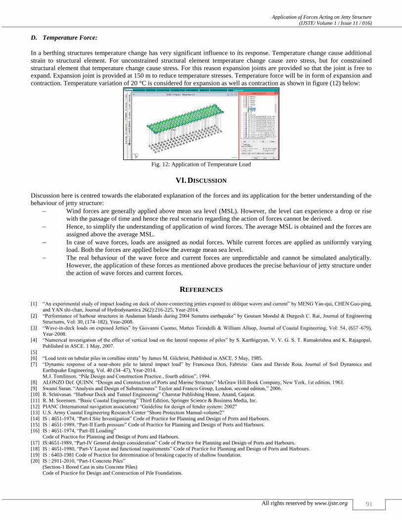
Here KDM & KIM factors are calculated according to Shore Protection Manual. Wave force acting over piles are calculated
from above expression & the maximum value obtained is 11.22 kN for normal wave while 34.38 kN for extreme wave case.
Wave force is applied as a point load at mean sea level on all the piles in both the direction as shown in fig. (10) below:
Fig. 10: Application of Current Load in Z-Direction
Differential Water Pressure: C.
In the case of waterfront structures with backfill, the pressure caused by difference in water levels at the fill side and the
waterside has to be taken into account in design. The magnitude of this hydrostatic pressure is influenced by the tidal range, free
water fluctuations, the ground water influx, the permeability of the foundation soil and the structure as well as the efficiency of
available backfill drainage.
In the case of good and poor drainage conditions of the backfill the differential water pressure may be calculated on the
guidelines given in figure (11). Here Jetty structure is open pile structure, so that differential water pressure will be absent in this
condition with reference (7)
.
Fig. 11: Differential Water Pressure
Application of Forces Acting on Jetty Structure (IJSTE/ Volume 1 / Issue 11 / 016)
All rights reserved by www.ijste.org
91
Temperature Force: D.
In a berthing structures temperature change has very significant influence to its response. Temperature change cause additional
strain to structural element. For unconstrained structural element temperature change cause zero stress, but for constrained
structural element that temperature change cause stress. For this reason expansion joints are provided so that the joint is free to
expand. Expansion joint is provided at 150 m to reduce temperature stresses. Temperature force will be in form of expansion and
contraction. Temperature variation of 20 °C is considered for expansion as well as contraction as shown in figure (12) below:
Fig. 12: Application of Temperature Load
VI. DISCUSSION
Discussion here is centred towards the elaborated explanation of the forces and its application for the better understanding of the
behaviour of jetty structure:
Wind forces are generally applied above mean sea level (MSL). However, the level can experience a drop or rise
with the passage of time and hence the real scenario regarding the action of forces cannot be derived.
Hence, to simplify the understanding of application of wind forces. The average MSL is obtained and the forces are
assigned above the average MSL.
In case of wave forces, loads are assigned as nodal forces. While current forces are applied as uniformly varying
load. Both the forces are applied below the average mean sea level.
The real behaviour of the wave force and current forces are unpredictable and cannot be simulated analytically.
However, the application of these forces as mentioned above produces the precise behaviour of jetty structure under
the action of wave forces and current forces.
REFERENCES
[1] “An experimental study of impact loading on deck of shore-connecting jetties exposed to oblique waves and current” by MENG Yan-qui, CHEN Guo-ping,
and YAN shi-chan, Journal of Hydrodynamics 26(2):216-225, Year-2014.
[2] “Performance of harbour structures in Andaman Islands during 2004 Sumatra earthquake” by Goutam Mondal & Durgesh C. Rai , Journal of Engineering Structures, Vol: 30, (174–182), Year-2008.
[3] “Wave-in-deck loads on exposed Jetties” by Giovanni Cuomo, Matteo Tirindelli & William Allsop, Journal of Coastal Engineering, Vol: 54, (657–679),
Year-2008. [4] “Numerical investigation of the effect of vertical load on the lateral response of piles” by S. Karthigeyan, V. V. G. S. T. Ramakrishna and K. Rajagopal,
Published in ASCE. 1 May, 2007.
[5] [6] “Load tests on tubular piles in coralline strata” by James M. Gilchrist, Published in ASCE. 5 May, 1985.
[7] “Dynamic response of a near-shore pile to lateral impact load” by Francesca Dezi, Fabrizio Gara and Davide Roia, Journal of Soil Dynamics and
Earthquake Engineering, Vol. 40 (34–47), Year-2014. M.J. Tomlinson. “Pile Design and Construction Practice., fourth edition”, 1994.
[8] ALONZO Def. QUINN. “Design and Construction of Ports and Marine Structure” McGraw Hill Book Company, New York, 1st edition, 1961.
[9] Swami Saran. “Analysis and Design of Substructures” Taylor and Francis Group, London, second edition,” 2006. [10] R. Srinivasan. “Harbour Dock and Tunnel Engineering” Charotar Publishing House, Anand, Gujarat.
[11] R. M. Sorensen. “Basic Coastal Engineering” Third Edition, Springer Science & Business Media, Inc.
[12] PIANC (International navigation association) “Guideline for design of fender system: 2002" [13] U.S. Army Coastal Engineering Research Center “Shore Protection Manual-volume2”
[14] IS : 4651-1974, “Part-I Site Investigation” Code of Practice for Planning and Design of Ports and Harbours.
[15] IS : 4651-1989, “Part-II Earth pressure” Code of Practice for Planning and Design of Ports and Harbours. [16] IS : 4651-1974, “Part-III Loading”
Code of Practice for Planning and Design of Ports and Harbours.
[17] IS:4651-1989, “Part-IV General design consideration” Code of Practice for Planning and Design of Ports and Harbours. [18] IS : 4651-1980, “Part-V Layout and functional requirements” Code of Practice for Planning and Design of Ports and Harbours.
[19] IS : 6403-1981 Code of Practice for determination of breaking capacity of shallow foundation.
[20] IS : 2911-2010, “Part-I Concrete Piles” (Section-1 Bored Cast in situ Concrete Piles)
Code of Practice for Design and Construction of Pile Foundations.


![Mathematical modelling of forces acting on ships during ...Mathematical modelling of forces acting on ships during lightering operations Evert Latairea,n, ... Nomenclature B [m]](https://img.pdfslide.net/doc/110x75/5a934e9f7f8b9a8b5d8c3077/mathematical-modelling-of-forces-acting-on-ships-during-mathematical-modelling.jpg)