Embed Size (px)
Citation preview
APPLICATION OF MICROCONTROLLER TO CONTROL PNEUMATIC ACTUATOR
MOHAMMAD SAFUAN BIN SHEAFI
Thesis submitted in fulfilment of the requirements for the award of the degree of
Bachelor of Mechanical Engineering
Faculty of Mechanical Engineering UNIVERSITI MALAYSIA PAHANG
DECEMBER 2010
ii
SUPERVISOR’S DECLARATION
I hereby declare that I have checked this project and in my opinion, this project is
adequate in terms of scope and quality for the award of the degree of Bachelor of
Mechanical Engineering.
Signature ....................................
Name of Supervisor: FIRDAUS BIN HASSAN
Position: LECTURER OF MECHANICAL ENGINEERING
Date: 6 DECEMBER 2010
iii
STUDENT’S DECLARATION
I hereby declare that the work in this project is my own except for quotations and
summaries which have been duly acknowledged. The project has not been accepted for
any degree and is not concurrently submitted for award of other degree.
Signature ..................................
Name: MOHAMMAD SAFUAN BIN SHEAFI
ID Number: MA07016
Date: 6 DECEMBER 2010
v
ACKNOWLEDGEMENTS
Alhamdulillah, praise to be Allah for His blessings and giving me the strength along the tough journey of completing my Final Year Project as well as this thesis writing, for without it, I would not have been able to come this far.
I would like to express my gratitude and appreciation to my old and new supervisor, Mr. Fadzil Faisae and Mr. Firdaus Hassan for their invaluable advice during the course of this project from the beginning till the end. Without their ideas and comments throughout the process of this project, this thesis would not be the same as presented here.
My outmost thanks also go to my family who has given me support throughout my academic years especially my parents. Many special thanks go to my fellow friends for the excellent understanding, co-operation, inspiration, and supports during my study here.
Last but not least, thanks to individuals that has contributed either directly or indirectly to make this thesis project. May Allah bless all of you. Amin.
vi
ABSTRACT
Pneumatics Technology is capable of utilizing the compressed air to perform work and
to organize functions. Pneumatic actuator, which is one of the elements in pneumatic
system, has been recognized for its flexibility to do various types of work and its
capability in diversity of applications. Commonly known controller to control the
pneumatic system movements is Programmable Logic Controller (PLC). However, the
cost of PLC is expensive for small automation system and it size basis can be consider
large as a controller. To overcome this problem, there is a new thought to use
Programmable Interface Controller (PIC) which is smaller and cheaper to replace PLC.
Main purpose of this project is to make the idea alive. This project will mainly
concerned on controlling the sequence of the three linear double-acting cylinder
actuator movements by using microcontroller PIC 18F452 coupled with pneumatic
solenoid valve. This microcontroller is used for controlling predefined sequences of
opening and closing of solenoid valves that will activate the actuator. A program in
MikroC PRO is written and developed to communicate with the microcontroller as to
move the actuator according to plan sequences. For purpose of voltage regulation, a
single-pole double throw (SPDT) relays are used as “OUTPUT” signal from the sensor
for the microcontroller. The “OUTPUT RELAY” is of the 6V SPDT powered from the
switching output voltage 5V dc of the microcontroller to convey the 24V dc to control
the solenoid pneumatic valve. The application that is going to be developed must be in a
low cost and a small scale basis. Subsequently, experimental simulation tests will be
conducted to evaluate the response and accuracy behaviour of the microcontroller
interacting with the solenoid valves.
vii
ABSTRAK
Teknologi Pneumatik mampu memanfaatkan tekanan untuk melakukan pekerjaan dan
untuk menetapkan fungsi. Pneumatik aktuator, yang merupakan salah satu unsur dalam
sistem pneumatik, telah diakui kerana fleksibilitinya untuk melakukan pelbagai jenis
pekerjaan dan kemampuan dalam kepelbagaian aplikasi. Umumnya untuk
mengendalikan gerakan sistem pneumatik, sistem kawalan yang digunakan adalah
Program Kawalan Logic (PLC). Namun, kos untuk sistem ini adalah mahal untuk sistem
automasi kecil dan saiznya boleh dianggap besar sebagai controller. Untuk mengatasi
masalah ini, ada pemikiran baru untuk menggunakan Program Kawalan Interface (PIC)
yang lebih kecil dan lebih murah untuk menggantikan PLC. Tujuan utama projek ini
dijalankan adalah untuk membuat idea itu hidup. Projek ini mengutamakan
pengendalian urutan tiga gerakan linear silinder berkembar dengan menggunakan
mikrokontroller, PIC18F452 digabungkan dengan injap pneumatik
solenoid. Mikrokontroler ini digunakan untuk mengawal urutan pembukaan dan
penutupan injap solenoid yang akan mengaktifkan aktuator. Sebuah program di MikroC
PRO ditulis dan dibangunkan untuk berkomunikasi dengan mikrokontroler untuk
menggerakkan aktuator sesuai dengan urutan rencana. Untuk tujuan regulasi voltan,
ganda kutub tunggal membuang (SPDT) relay digunakan sebagai isyarat "OUTPUT"
dari sensor untuk mikrokontroler. Simbol "OUTPUT RELAY" adalah dari SPDT 6V
kuasa voltan keluar dari suis 5V dc dari mikrokontroler untuk menyampaikan dc 24V
untuk mengawal injap pneumatik solenoid. Aplikasi yang akan dibangunkan harus
dengan kos yang rendah dan dasar skala kecil. Selanjutnya, ujian simulasi eksperimen
akan dilakukan untuk menilai perilaku respon dan ketepatan dari mikrokontroler
berinteraksi dengan injap solenoid.
viii
TABLE OF CONTENTS
Page
SUPERVISOR’S DECLARATION ii
STUDENT’S DECLARATION iii
DEDICATION iv
ACKNOWLEDGEMENTS v
ABSTRACT vi
ABSTRAK vii
TABLE OF CONTENTS viii
LIST OF TABLES xii
LIST OF FIGURES xiii
LIST OF SYMBOLS viii
LIST OF ABBREVIATIONS xvi
CHAPTER 1 INTRODUCTION
1.1 Project Background 1
1.3 Problem Statement 2
1.3 Project Objectives 2
1.4
1.5
Project Scopes
Outline of Thesis
3
3
ix
CHAPTER 2 THEORY AND LITERATURE REVIEW
2.1 Introduction 4
2.2 Controller 2.2.1 Quick Review on PLC and PIC 2.2.2.1 Programmable Logic Controller (PLC) 2.2.2.2 Programmable Interface Controller (PIC) 2.2.2 Difference Between PLC and PIC
4 5 5 6 7
2.3 Electro Pneumatic System 2.3.1 Power Source 2.3.2 Control Valve 2.3.2.1 Ports and Positions 2.3.2.2 Function Principle
7 8 8 9
10 2.3.3 Actuator
2.3.3.1 Basic Actuator Functioning 2.3.3.2 Measurement of Force 2.3.4 Sensor
11 12 12 14
2.4 Relay 2.4.1 Basic Principles 2.4.2 Types of Relay 2.4.2.1 SPST 2.4.2.2 SPDT
14 15 16 16 17
2.5 Transistor Circuit 18
2.6 Microcontroller 19
2.7 Programming 2.7.1 Boolean Flow Control 2.7.2 Operator
21 21 22
2.8 Cost
23
2.9 Relevance of the Literature Review 24
x
CHAPTER 3 RESEARCH METHODOLOGY
3.1 Introduction 25
3.2 Application Design 3.2.1 Drilling Machine Pneumatically Controlled 3.2.2 Displacement Step Diagram
26 27 28
3.3 Component Selection 3.3.1 Mechanical Components 3.3.1.1 5/2 Way Single Solenoid Valve 3.3.1.2 Double Acting Actuator 3.3.1.3 Magnetic Sensor 3.3.2 Electronic Components 3.3.2.1 PIC 18F452 3.3.2.2 SPDT Relay 3.3.2.3 NPN Transistor 3.3.2.4 Diode IN4007
29 29 29 30 31 32 32 33 34 34
3.4 System Circuit Design 35 3.4.1 Schematic System Diagram 35 3.4.2 Electronic Board Circuit
3.4.2.1 Input Circuit 3.4.2.2 Controller Circuit (PIC18F452) 3.4.2.3 Output Circuit 3.4.3 Circuit Summary
36 36 37 38 40
3.5 Programming 3.5.1 Mikro-C Pro 3.5.2 Coding
41 42 43
3.6 Conclusion of Chapter 44
xi
CHAPTER 4 RESULTS AND DISCUSSION
4.1 Introduction 45
4.2 Movement of Actuators 45
4.3 Pneumatic System and Circuit Integration 47
4.4 Cost Analysis 4.4.1 PLC’s Cost 4.4.2 PIC’s Cost 4.4.2 Cost Discussion
49 50 51 52
4.5 Program Steps 54
4.6 Conclusion of Chapter 60
CHAPTER 5 CONCLUSION AND RECOMMENDATIONS
5.1 Introduction 61
5.2 Conclusion 61
5.3 Recommendations For Future Work 62
REFERENCES 63
APPENDICES
A Gantt Chart for FYP 1 65
B Gantt Chart for FYP 2 66
C Magnetic Sensor 67
D Jazari2u Quotation 68
xii
LIST OF TABLES
Table No. Title Page 2.1 Comparisons between PIC and PLC 7 2.2 Port markings of directional control valves 10 2.3 C language operators 23 3.1 General Specification of valve selected 30 3.2 Specification of cylinder actuator 31 3.3 Specification of magnetic sensor 32 3.4 Features of PIC18F452 33 3.5 Ports of PIC18F452 and its function. 38 3.6 Total components involved 40 4.1 Total unit cost for PLC and PIC on each unit 53 4.2 Selected microcontroller port 55 4.3 Microcontroller input and output table 56 4.4 Actuators divided into groups 56

xiii
LIST OF FIGURES
Figure No. Title Page 2.1 Feedback controls system 4 2.2 Basic elements of a pneumatic system 8 2.3 5/2 valve illustrated 9 2.4 5/2 Ways Solenoid Spring Return Valve 10 2.5 Movement of actuator before and after coil is actuated 11 2.6 A pneumatic cylinder 12 2.7 Thrust in pneumatic cylinder. 13 2.8 Magnetic sensor circuit 14 2.9 Basic relay 15 2.10 SPST symbol 16 2.11 SPDT symbol 17 2.12 Transistor circuit 17 2.13 Push button circuit 20 2.14 Crystal circuit 20 2.15 Voltage regulator circuit 21 2.16 If-else-if control structure 22 3.1 Flow works 26 3.2 Basic sketching of application design 27 3.3 Displacement-step diagram for the application 28 3.4 5/2 way single solenoid valve 29 3.5 XCPC pneumatic actuator 30 3.6 XCPC magnetic sensor 31
xiv
3.7 Microcontroller PIC18F452 33 3.8 6V SPDT relay 33 3.9 General PNP transistor 34 3.10 IN4007 diode 34 3.11 Overall system schematic diagram 35 3.12 Input sensor circuit 36 3.13 Microcontroller basic circuit 37 3.14 Output circuit 38 3.15 Flowchart of programming design 41 3.16 Mikro-C pro 42 3.17 Usbpicprog 42 4.1 Actuator movement flowchart 46 4.2 Complete circuit board 47 4.3 Pneumatic system 48 4.4 Complete application circuit 48 4.5 Cost of PLC and PIC 53 4.6 Pneumatic circuit 54 6.1 Gantt Chart for FYP 1 65 6.2 Gantt Chart for FYP 2 66
xv
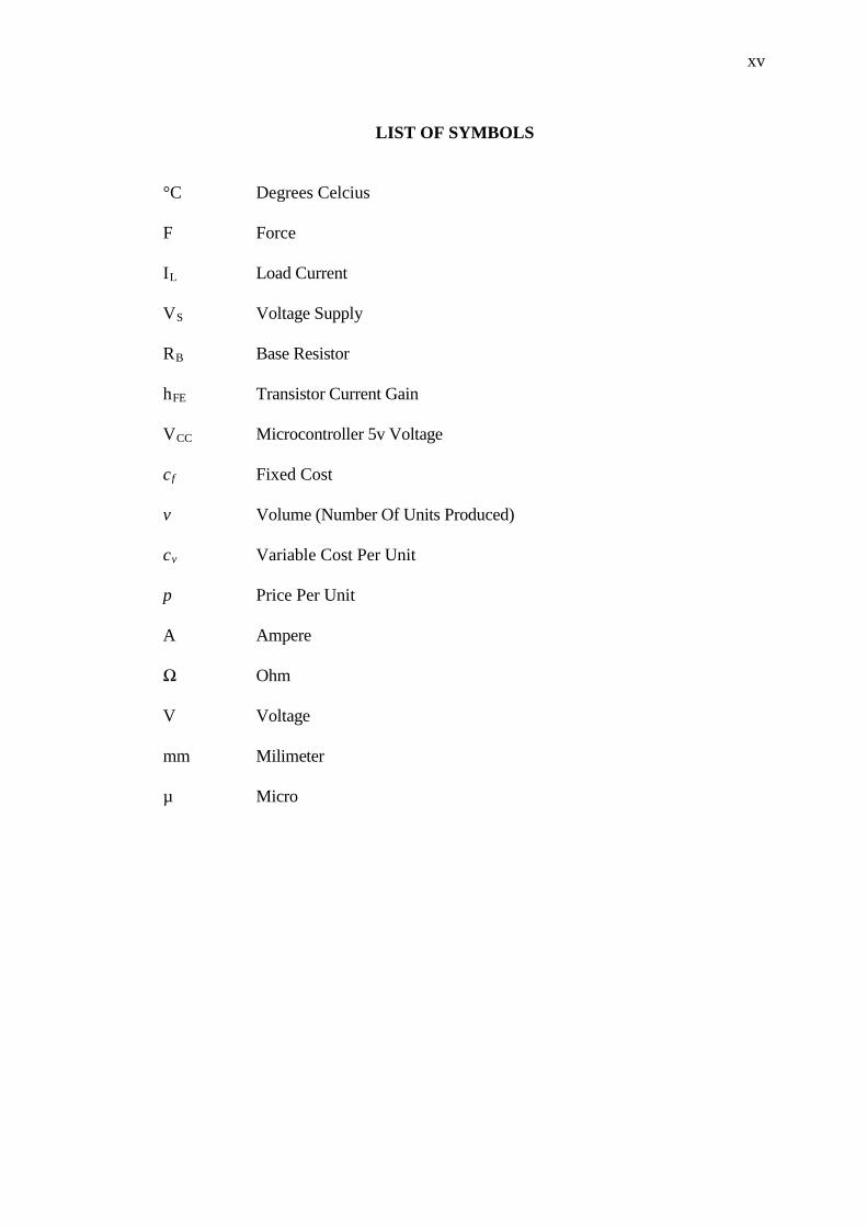
LIST OF SYMBOLS
°C Degrees Celcius F Force I Load Current L V Voltage Supply S R Base Resistor B h Transistor Current Gain FE V Microcontroller 5v Voltage CC c Fixed Cost f v Volume (Number Of Units Produced) c Variable Cost Per Unit v p Price Per Unit A Ampere Ω Ohm V Voltage mm Milimeter µ Micro
xvi
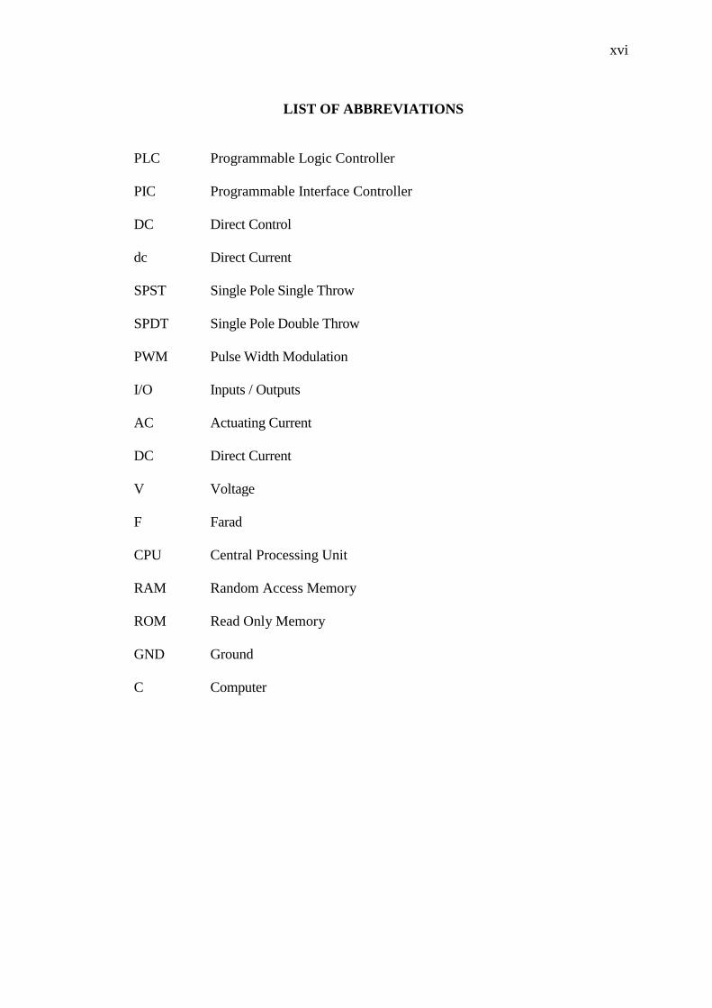
LIST OF ABBREVIATIONS
PLC Programmable Logic Controller PIC Programmable Interface Controller DC Direct Control dc Direct Current SPST
Single Pole Single Throw
SPDT Single Pole Double Throw PWM Pulse Width Modulation I/O Inputs / Outputs AC Actuating Current DC Direct Current V Voltage F Farad CPU Central Processing Unit RAM Random Access Memory ROM Read Only Memory GND Ground C Computer
CHAPTER 1
INTRODUCTION
1.1 PROJECT BACKGROUND
The automation systems that use electro-pneumatic technology are formed by
mainly three kinds of elements: actuators or motors, sensors or buttons and control
elements. Nowadays, most of the control elements in the industries use PLC to execute
the logic of the system. Sensors and switches are designed as inputs and the direct
control valves for the actuators are designed as outputs. All the logic necessary to the
sequence of the movements, simulates other components like counter, timer and control
the status of the system is based on internal programmed. With the use of the PLC, the
project wins agility, because it is possible to create and simulate the system as many
times as needed. (Nyein A.A, 2008). Therefore time can be saved, risk of mistakes can
be reduced and complexity can be increased using the same elements.
However, an alternative in this case is to create a specific controller that can
offer the exact size and resources that the project needs. This is made using
microcontrollers as the base of this controller. The controller, which is made with the
utilization of microcontroller, can be very specific and adapted to only one kind of
machine or it can work as a generic controller that can be programmed as a usual PLC
and work with logic that can be changed. All these characteristics depend on what is
2
needed and how much experience the designer has in developing an electronic circuit
and a program for microcontroller
1.2 PROBLEM STATEMENT
The PLC has come a long way from its development and establishment since its
ability to work in any conditions and make it the only choice when process control is
required. However, in some applications, the PLC offers too many resources that are not
even used to control the system especially for small sized system. Problems with the
PLC are as identified below:
i. Existed PLC is expensive for small system.
ii. Larger space required to place it.
iii. High voltage used.
iv. Difficult to change the existed control system.
1.3 PROJECT OBJECTIVES
The objectives of this project are to:
i. Build PIC circuit to control valves sequences and counter to move pneumatic
actuator.
ii. Integrate PIC with pneumatic system.
iii. Reduce price of existed PLC controller system.
iv. Compare the price with existed PLC.
3
1.4 PROJECT SCOPES
In order to achieve objectives of this project, certain scopes have been outlined.
The scopes are:
i. System must consists of three linear cylinder double-acting actuators.
ii. Only functionality of microcontroller interacting with the actuators is evaluated.
iii. Motion and the movement planning application of the actuators is tested
iv. The system is a closed system.
1.5 OUTLINE OF THESIS
This thesis consists of four chapters. In first chapter, it describes overall
framework of basic information of this project. In Chapter 2, it focuses various reviews
on theoretical study to this project. It will discuss about the system and general info for
each components involved.
While in Chapter 3, the method of research regarding on system description and
the hardware and software implementation is elaborated. Pre-analysis on calculations
that have been reviewed in Chapter 2 is shown in this chapter too. These calculations
are vital for material selection. Finally, results and discussion will be discussed in
Chapter 4 and conclusion and recommendation will be provided in Chapter 5.
CHAPTER 2
THEORY AND LITERATURE REVIEW
2.1 INTRODUCTION
This chapter concerns on basic principles of controller system. Also, it covers on
general information on PLC and microcontroller which commonly known as PIC. It
also includes basic study on components involved in pneumatic system for further
understanding of this project. The facts and information gained from reliable sources
and is elaborated based on understanding of the review.
2.2 CONTROLLER
Controller is indeed important to manage, command, direct or regulate the
behaviour of other devices or systems.
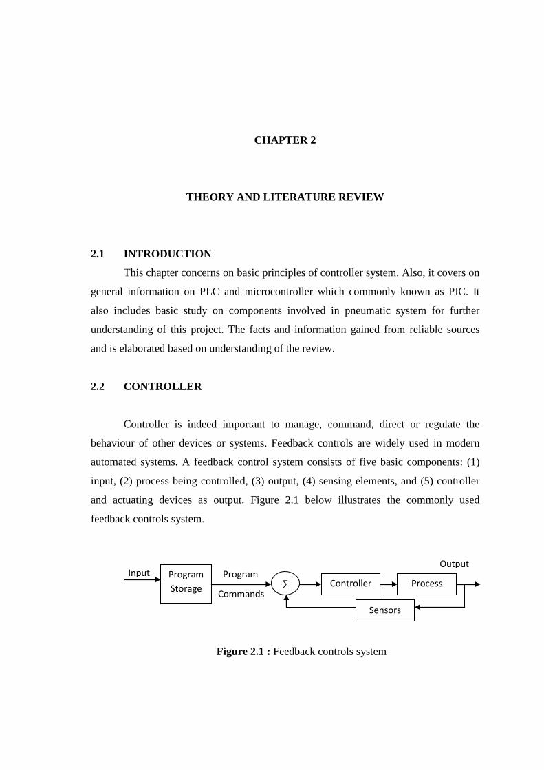
Feedback controls are widely used in modern
automated systems. A feedback control system consists of five basic components: (1)
input, (2) process being controlled, (3) output, (4) sensing elements, and (5) controller
and actuating devices as output. Figure 2.1 below illustrates the commonly used
feedback controls system.
Figure 2.1 : Feedback controls system
Input
Output
Commands
Program Program Storage Controller Process
Sensors
∑
5
Commonly used controller to control logic circuit is PLC. However, there is a
new idea to replace this PLC with more compact and smaller controller that is called
PIC. Quick review on PLC and PIC are shown as below.
2.2.1 Quick Review on PLC and PIC
In this subchapter, history of PIC and PLC and their working principles will be
provided. Yet, advantages and disadvantages for PLC and PIC are more focused on. All
the information provided will be summarized into a table based on their criteria.
2.2.1.1 Programmable Logic Controller (PLC)
Programmable Logic Controller was invented to replace relay control systems.
More improvements to PLC occurred in the 1970’s and 1980's. In the 70’s, the ability to
communicate between PLC was added. This also made it possible to have the
controlling circuit quite a ways away from the machine it was controlling. While in the
1980’s, the size of PLCs was reduced to use space more efficiently. (Amunrud A, 2002)
A PLC generally does three basic things: check the inputs, run through the
program, and change the outputs. It then loops back to the top and starts again. It is
fundamentally a relay control systems that is combine into a package. This means that a
PLC is consist of:
i. Input and output relays: send and receive information from the outside world.
ii. Counters: how fast the PLC counters the information.
iii. Timers: how long the output stays changed once the input is provided.
iv. Data storage registers: save data after programming.
PLCs are very good for controlling outputs depending on inputs. They are
remarkably robust, and able to stand all sorts of difficult conditions, such as extreme
temperatures or dust in the air. It can withstand 0°C to 60°C during operating. They do
not have contacts that wear out. They also can switch fairly quickly without heating up
much, in direct contrast to relays. This means that cooling costs are decreased.
6
On the downside, PLCs are not very good at handling large amount of data, or
complex data. There is limited amount of data storage. Plus, user cannot simply choose
any i/o as input or output. Amount of inputs and outputs are set up by the manufacturer.
2.2.1.2 Programmable Interface Controller (PIC)
Microcontroller has gained its popularity among control systems builders due to
its size, cost and the performance of the microcontroller which is way better compared
to the existed control system.
A microcontroller is the combination of a microprocessor, memory, input and
output ports and some of the special functions like timer, analogue to digital converter,
mathematics processor and PWM generator in one chip. A microcontroller will take an
input from a device it is controlling hence controls the device by sending signals to
different components in the device.
Due to the availability of a number of resources such as multiple input-output,
timers, serial interface and others, the microcontroller is today used for number of front
end applications and stand alone systems. It is now tradition to convert analog and
digital circuits to microcontroller based system because of the additional advantages
provided by the microcontroller, such as:
i. ability and ease of computation.
ii. relatively small size.
iii. reasonable cost.
Their temperature properties depend on the manufacturer. Normally they can
withstand temperature from 0°C to 80°C during operating. [Dole N.E, 2003]
7
2.2.2 Difference Between PLC and PIC
Based on general review on PIC and PLC, their different properties can be
simplified into Table 2.1.
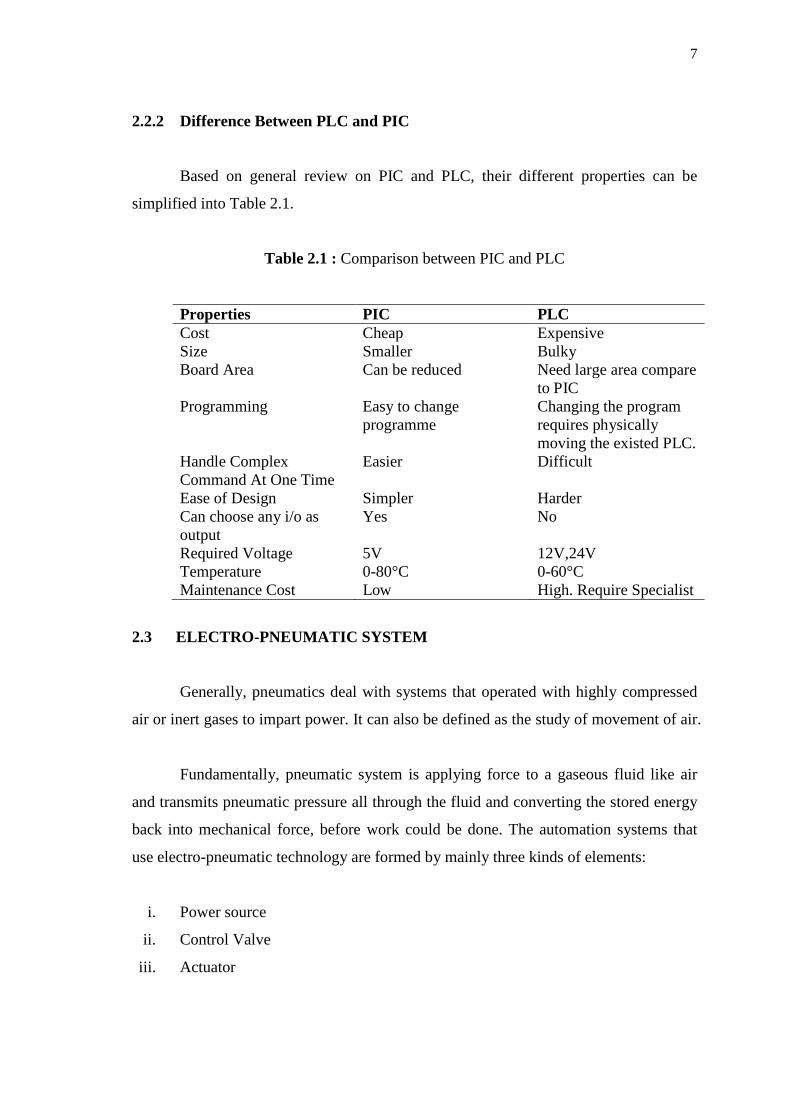
Table 2.1 : Comparison between PIC and PLC
Properties PIC PLC Cost Cheap Expensive Size Smaller Bulky Board Area Can be reduced Need large area compare
to PIC Programming Changing the program
requires physically moving the existed PLC.
Easy to change programme
Handle Complex Command At One Time
Difficult Easier
Ease of Design Harder Simpler Can choose any i/o as output
No Yes
Required Voltage 12V,24V 5V Temperature 0-80 0-60°C °C Maintenance Cost High. Require Specialist Low
2.3 ELECTRO-PNEUMATIC SYSTEM
Generally, pneumatics deal with systems that operated with highly compressed
air or inert gases to impart power. It can also be defined as the study of movement of air.
Fundamentally, pneumatic system is applying force to a gaseous fluid like air
and transmits pneumatic pressure all through the fluid and converting the stored energy
back into mechanical force, before work could be done. The automation systems that
use electro-pneumatic technology are formed by mainly three kinds of elements:
i. Power source
ii. Control Valve
iii. Actuator
8
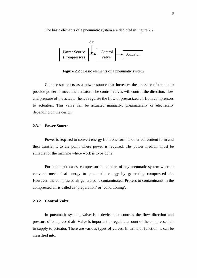
The basic elements of a pneumatic system are depicted in Figure 2.2.
Figure 2.2 : Basic elements of a pneumatic system
Compressor reacts as a power source that increases the pressure of the air to
provide power to move the actuator. The control valves will control the direction; flow
and pressure of the actuator hence regulate the flow of pressurized air from compressors
to actuators. This valve can be actuated manually, pneumatically or electrically
depending on the design.
2.3.1 Power Source
Power is required to convert energy from one form to other convenient form and
then transfer it to the point where power is required. The power medium must be
suitable for the machine where work is to be done.
For pneumatic cases, compressor is the heart of any pneumatic system where it
converts mechanical energy to pneumatic energy by generating compressed air.
However, the compressed air generated is contaminated. Process to contaminants in the
compressed air is called as ‘preparation’ or ‘conditioning’.
2.3.2 Control Valve
In pneumatic system, valve is a device that controls the flow direction and
pressure of compressed air. Valve is important to regulate amount of the compressed air
to supply to actuator. There are various types of valves. In terms of function, it can be
classified into:
Control Valve
Actuator Power Source (Compressor)
Air
9
i. Directional control valves : Control the flow direction of compressed air.
ii. Non-return valves : Allow flow of compressed only in one direction.
iii. Pressure control valves : Limit the pressure of compressed air supplied.
iv. Flow control valves : Restrict the compressed air to reduce its flow rate.
However, this project only concern on directional control solenoid valves since
this project main components are utilizing electrical signal to control flow of
compressed air and movement of the actuator.
2.3.2.1 Ports and Positions
Directional control valves are differentiated on the number of ports and valve
position. It is generally satisfied as ‘port/position valve’. Port refers to number of ports
while position valve refers to number of switching position for the valve.
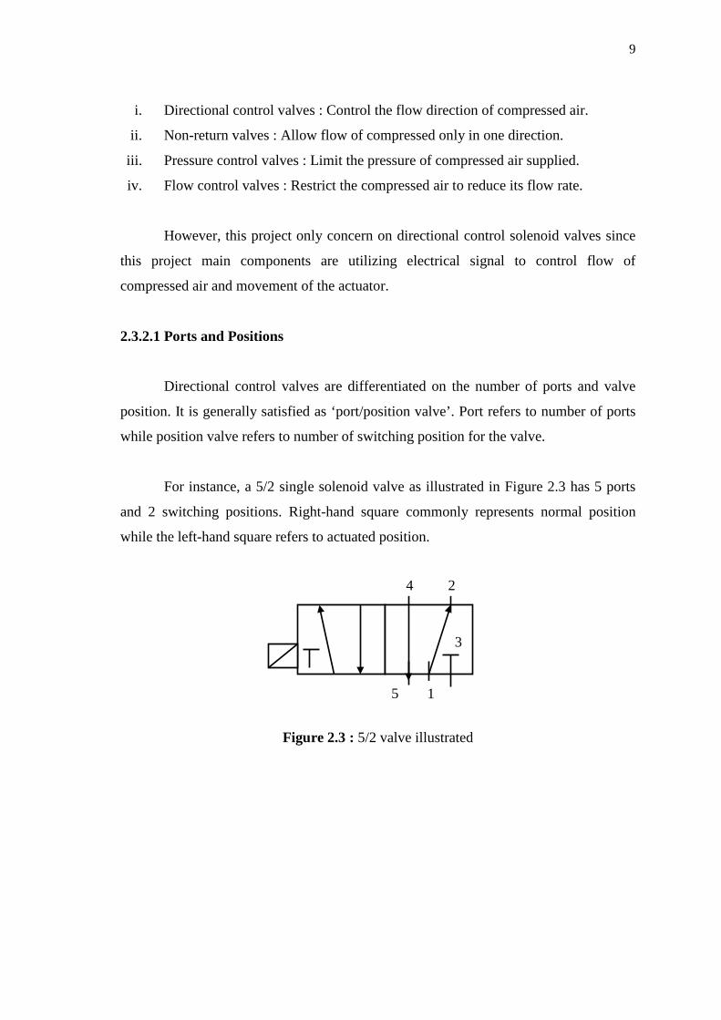
For instance, a 5/2 single solenoid valve as illustrated in Figure 2.3 has 5 ports
and 2 switching positions. Right-hand square commonly represents normal position
while the left-hand square refers to actuated position.
Figure 2.3 : 5/2 valve illustrated
5 1
3
2 4