Embed Size (px)
Citation preview
1
Applications in Convective Heat Transferwith
Emphasis on Blade Cooling Flows
Par t I , Background & Methodologies
Dr Hector I acovidesDepar tment of Mechanical Aerospace and
Manufactur ing EngineeringUMI ST
Contents
1. Heat Convection and Role of Turbulence.2. Role of CFD in Heat Convection Analysis.3. Blade Cooling Flows and Flow Features
Present.4. Overview of the Numerical and Modeling
Methodologies followed at UMI ST.5. Concluding Remarks.
2
1. Heat Convection and Role of Turbulence
1.1Basics
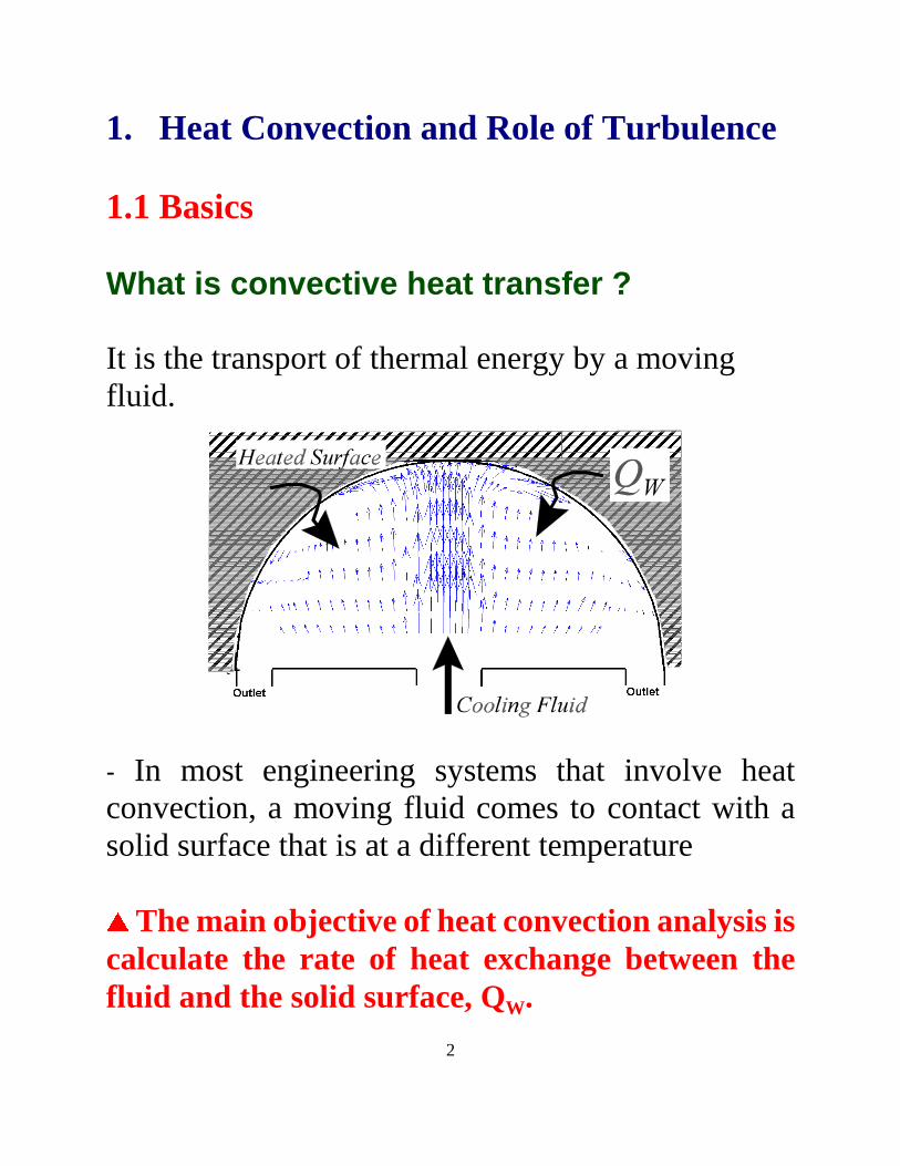
What is convective heat transfer ?
It is the transport of thermal energy by a movingfluid.
- In most engineering systems that involve heatconvection, a moving fluid comes to contact with asolid surface that is at a different temperature
�� The main objective of heat convection analysis is
calculate the rate of heat exchange between thefluid and the solid sur face, QW.
3
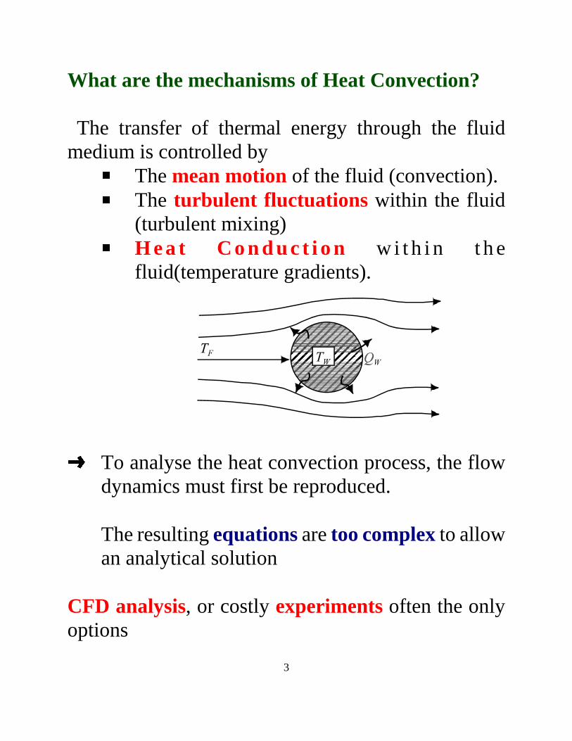
What are the mechanisms of Heat Convection?
The transfer of thermal energy through the fluidmedium is controlled by � The mean motion of the fluid (convection).� The turbulent fluctuations within the fluid
(turbulent mixing)� H eat Conduct i on wi t hi n t hefluid(temperature gradients).
�To analyse the heat convection process, the flowdynamics must first be reproduced.
The resulting equations are too complex to allowan analytical solution
CFD analysis, or costly experiments often the onlyoptions
4
Natural ConvectionForced Convection
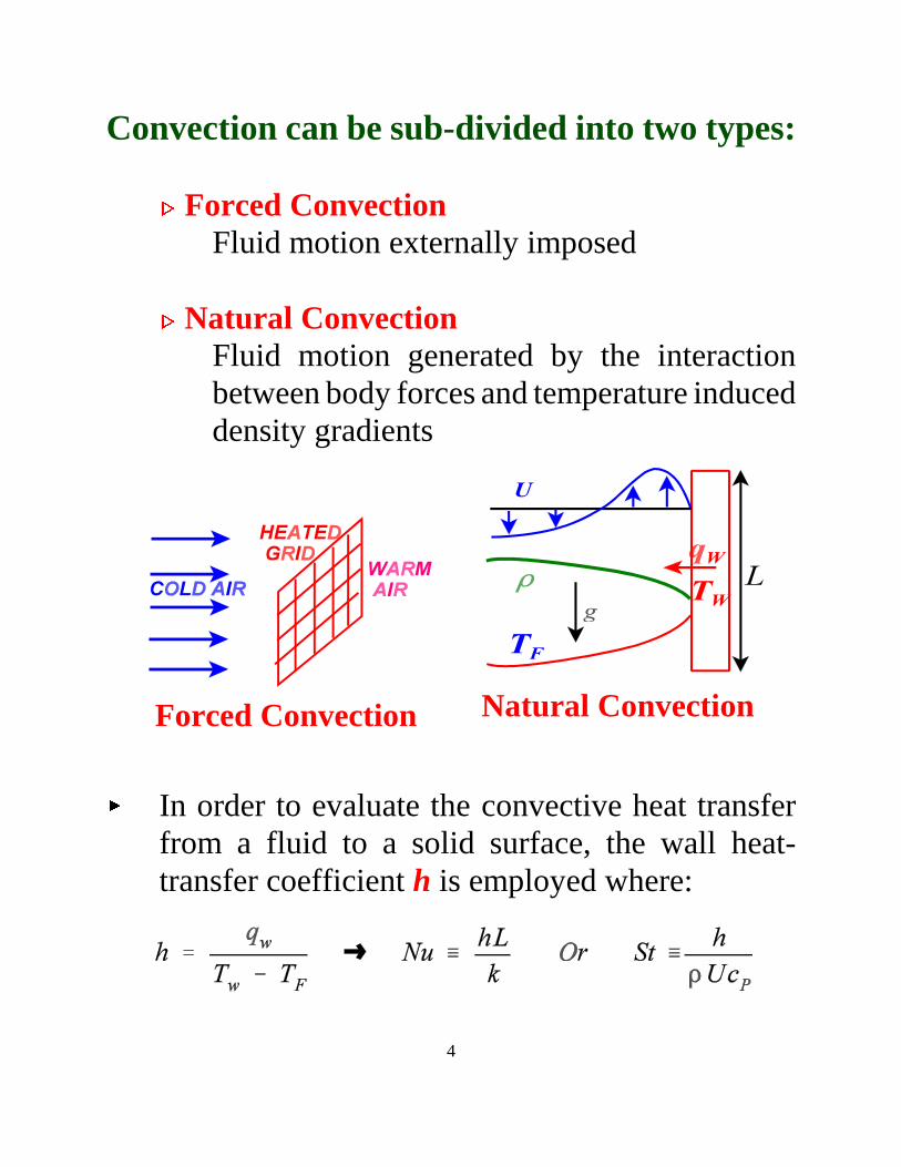
Convection can be sub-divided into two types:
�� Forced Convection Fluid motion externally imposed
�� Natural Convection Fluid motion generated by the interactionbetween body forces and temperature induceddensity gradients
� In order to evaluate the convective heat transferfrom a fluid to a solid surface, the wall heat-transfer coeff icient h is employed where:
5
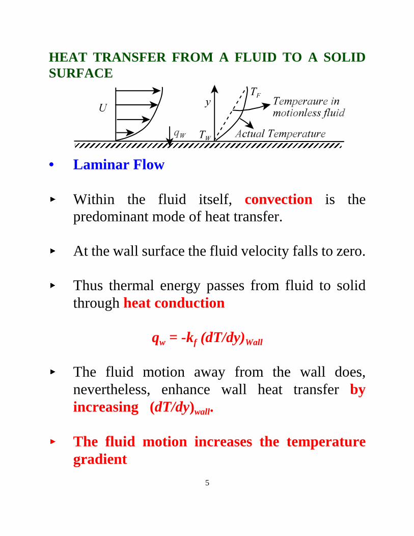
HEAT TRANSFER FROM A FLUID TO A SOLIDSURFACE
• Laminar Flow
� Within the fluid itself, convection is thepredominant mode of heat transfer.
� At the wall surface the fluid velocity falls to zero.
� Thus thermal energy passes from fluid to solidthrough heat conduction
qw = -kf (dT/dy)Wall
� The fluid motion away from the wall does,nevertheless, enhance wall heat transfer byincreasing (dT/dy)wall.
� The fluid motion increases the temperaturegradient
6
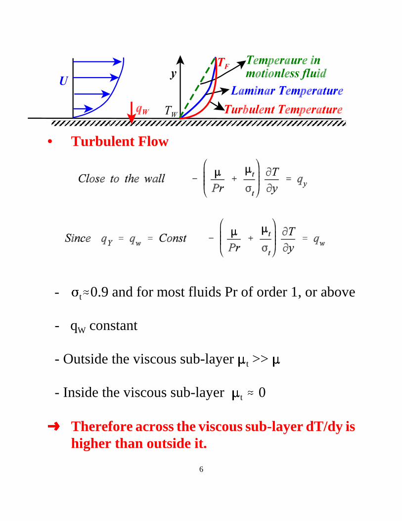
• Turbulent Flow
- � t 0.9 and for most fluids Pr of order 1, or above
- qW constant
- Outside the viscous sub-layer t >>
- Inside the viscous sub-layer t � 0
� Therefore across the viscous sub-layer dT/dy ishigher than outside it.
7
• Thus the viscous sub-layer produces most ofthe thermal resistance to the transfer ofthermal energy between a turbulent fluid anda solid sur face.
In Turbulent Heat Convection, the Wall Heat Fluxis controlled by the thickness of the viscous sub-layer.
8
2. Role of CFD in Heat Convection Analysis
- The computation of convective heat transfer isnecessary in many engineering processes.
- In many applications, all that is needed is theaverage value of the coeff icient of wall heat flux.
- Increasingly there is a need for more detailedinformation on the var iation of the local Nusseltmember.
- It here that CFD has the potential to make animpact in engineering analysis and development.
- In most applications of practical interest, the flowtends to be complex, three-dimensional andturbulent.
- Numerical methods, therefore, need to be able to
� Resolve the complex three-dimensionalfeatures of the mean motion with numericalaccuracy.
9
� Use turbulence models that correctlyaccount for the effects of turbulence incomplex flows. � Employ turbulence models that can alsofaithfully reproduce the effects of turbulenceacross the viscous sub-layer.
- Progress has been diff icult, because of:
� The heavy computational demands involved� The lack of detailed experimental data forvalidation.
- Our group at UMIST has been engaged in bothnumerical and experimental investigations ofconvective heat transfer problems mainly related to theinternal cooling of gas-turbine blades.
- Most of the flow features encountered also presentin other applications
- Most of the conclusions reached also relevant tothe computation of turbulent convective heat transferin general
10
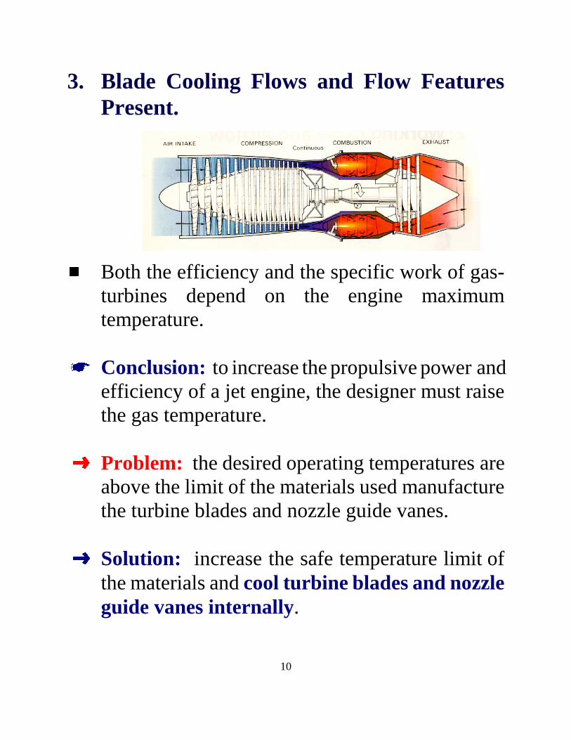
3. Blade Cooling Flows and Flow FeaturesPresent.
��Both the eff iciency and the specific work of gas-turbines depend on the engine maximumtemperature.
� Conclusion: to increase the propulsive power andeff iciency of a jet engine, the designer must raisethe gas temperature.
� Problem: the desired operating temperatures areabove the limit of the materials used manufacturethe turbine blades and nozzle guide vanes.
� Solution: increase the safe temperature limit ofthe materials and cool turbine blades and nozzleguide vanes internally.
11
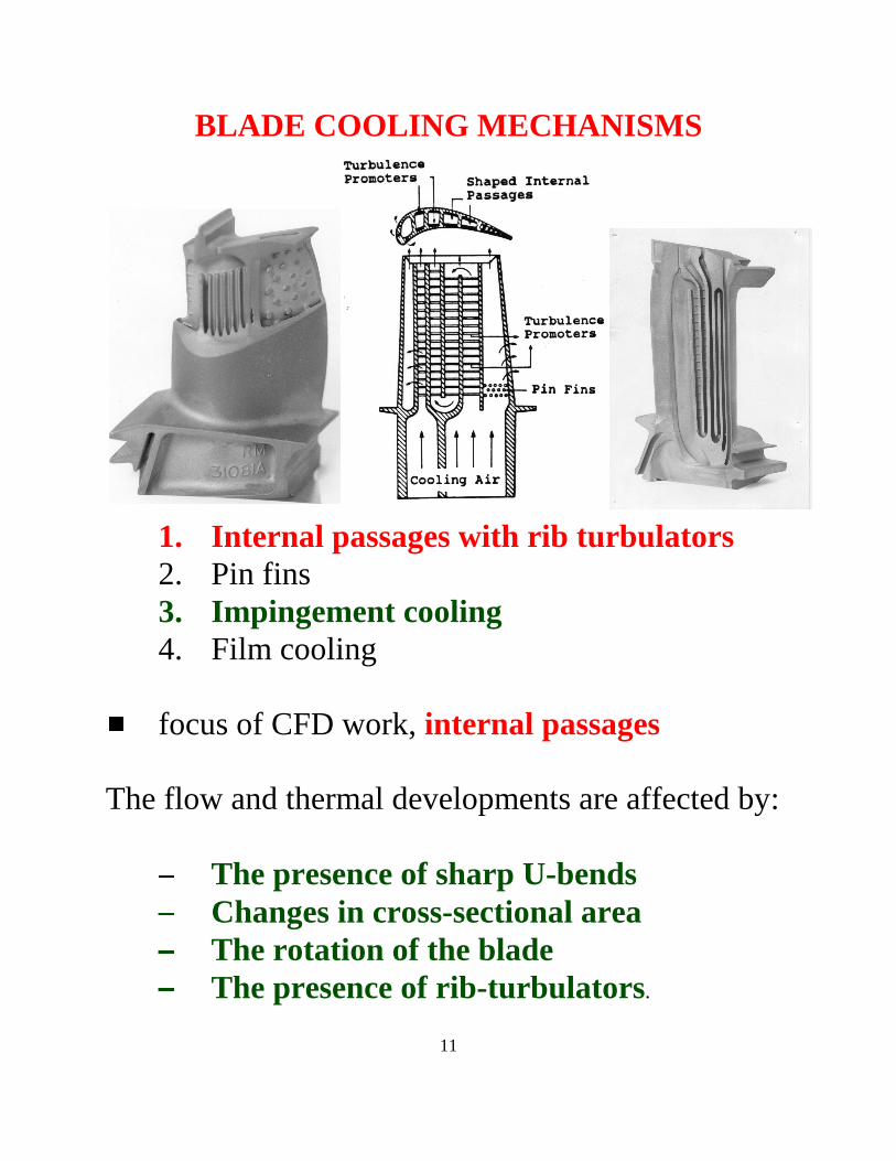
BLADE COOLING MECHANISMS
1. Internal passages with r ib turbulators2. Pin fins3. Impingement cooling4. Film cooling
�focus of CFD work, internal passages
The flow and thermal developments are affected by:
� The presence of sharp U-bends�� Changes in cross-sectional area�� The rotation of the blade�� The presence of r ib-turbulators.
12
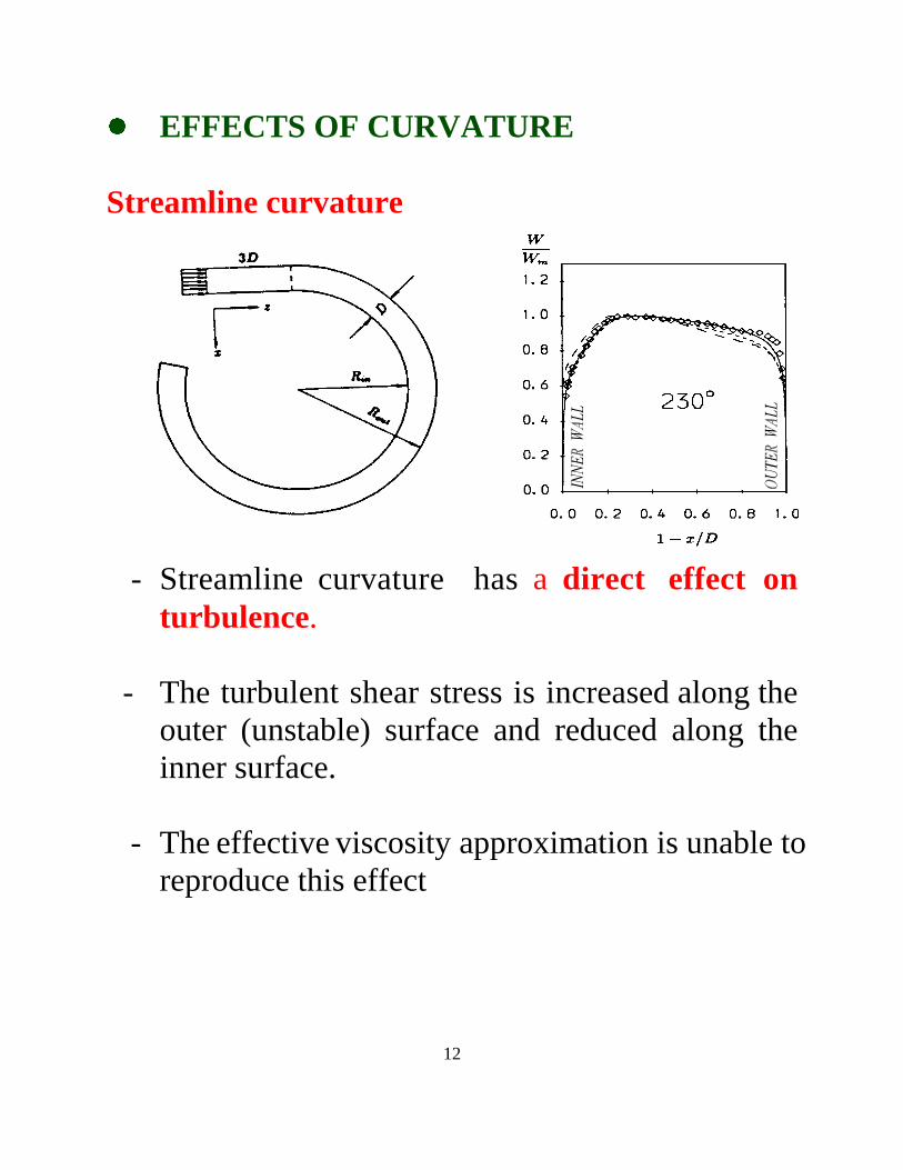
��EFFECTS OF CURVATURE
Streamline curvature
- Streamline curvature has a direct effect onturbulence.
- The turbulent shear stress is increased along theouter (unstable) surface and reduced along theinner surface.
- The effective viscosity approximation is unable toreproduce this effect
13
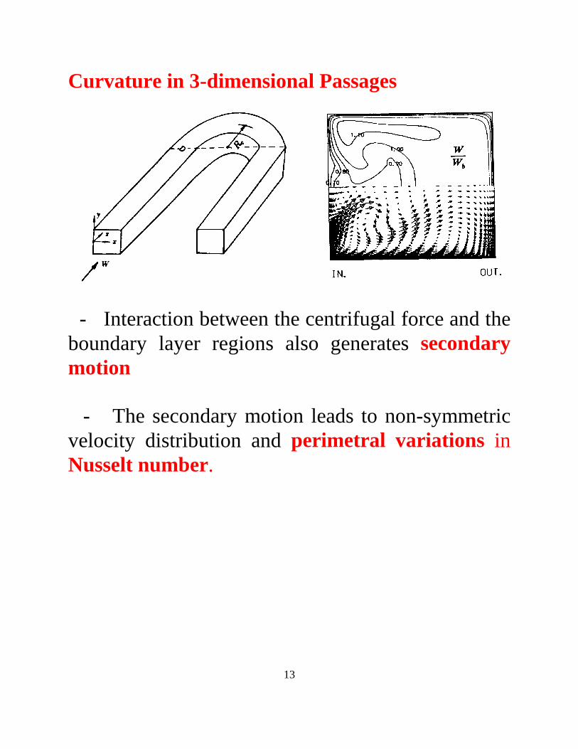
Curvature in 3-dimensional Passages
- Interaction between the centrifugal force and theboundary layer regions also generates secondarymotion
- The secondary motion leads to non-symmetricvelocity distribution and perimetral var iations inNusselt number.
14
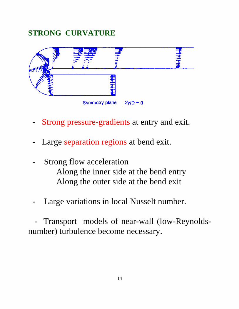
STRONG CURVATURE
- Strong pressure-gradients at entry and exit.
- Large separation regions at bend exit.
- Strong flow acceleration Along the inner side at the bend entry
Along the outer side at the bend exit
- Large variations in local Nusselt number.
- Transport models of near-wall (low-Reynolds-number) turbulence become necessary.
15
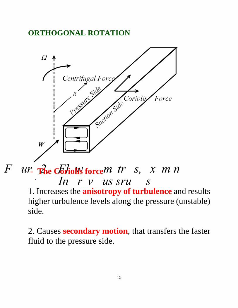
ORTHOGONAL ROTATION
- The Cor iolis force
1. Increases the anisotropy of turbulence and resultshigher turbulence levels along the pressure (unstable)side.
2. Causes secondary motion, that transfers the fasterfluid to the pressure side.
16
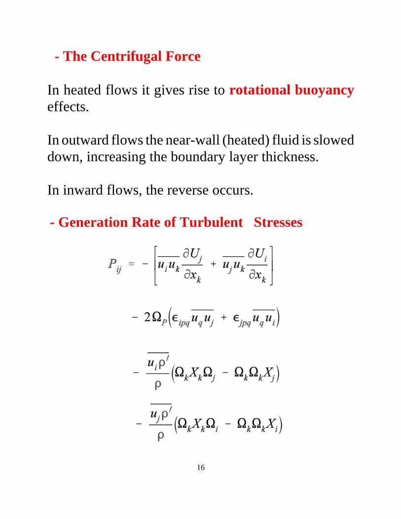
- The Centr ifugal Force
In heated flows it gives rise to rotational buoyancyeffects.
In outward flows the near-wall (heated) fluid is sloweddown, increasing the boundary layer thickness.
In inward flows, the reverse occurs.
- Generation Rate of Turbulent Stresses
17
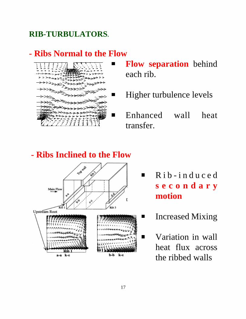
RIB-TURBULATORS.
- Ribs Normal to the Flow� Flow separation behindeach rib.
� Higher turbulence levels
� Enhanced wall heattransfer.
- Ribs Inclined to the Flow
� R i b - i n d uc eds e c o n d a r ymotion
� Increased Mixing
� Variation in wallheat flux acrossthe ribbed walls
18
4. Overview of the Numerical and ModelingMethodologies followed at UMI ST.
4.1 Numerical Framework
- Finite-volume flows solvers
- Pressure correction method.
- Bounded 3rd Order QUICK scheme for thediscretization of convective transport of all flowvariables.
- For simple geometries 2-D, or 3-D fixed co-ordinate codes employed.
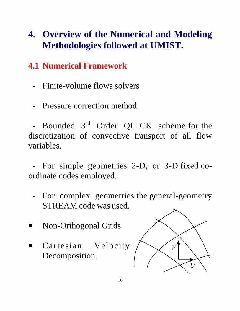
- For complex geometries the general-geometrySTREAM code was used.
� Non-Orthogonal Grids
� Cartesi an V el ocit yDecomposition.
19
- Flow equations include rotation terms.
- Additional stabilit y measures included for second-moment closures and non-linear eddy-viscosity,models.
4.2 Turbulence Modeling
�Main objective of studies, the validation ofturbulence modeling practices.
� Different modeling practices have been tested.
�Models employed in the main flow regions � effective-viscosity model � second-moment algebraic models � second-moment differential models � non-linear k- � .
.�Models employed in the near-wall regions. Conventional Wall -functions Zonal (2-layer) models Low-Reynolds-number models
20
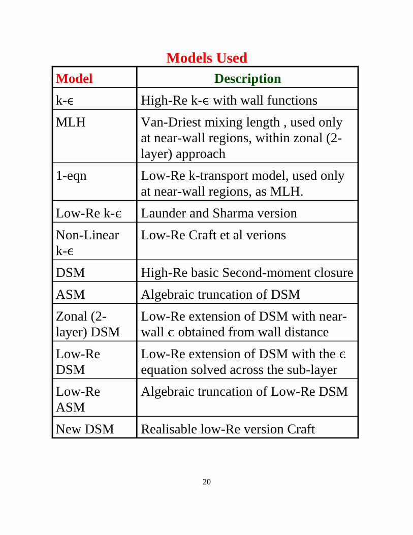
Models UsedModel Description
k- ! High-Re k- ! with wall functions
MLH Van-Driest mixing length , used onlyat near-wall regions, within zonal (2-layer) approach
1-eqn Low-Re k-transport model, used onlyat near-wall regions, as MLH.
Low-Re k- ! Launder and Sharma version
Non-Lineark- !
Low-Re Craft et al verions
DSM High-Re basic Second-moment closure
ASM Algebraic truncation of DSM
Zonal (2-layer) DSM
Low-Re extension of DSM with near-wall ! obtained from wall distance
Low-ReDSM
Low-Re extension of DSM with the !equation solved across the sub-layer
Low-ReASM
Algebraic truncation of Low-Re DSM
New DSM Realisable low-Re version Craft
21
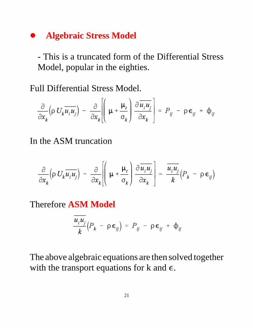
"#Algebraic Stress Model
- This is a truncated form of the Differential StressModel, popular in the eighties.
Full Differential Stress Model.
In the ASM truncation
Therefore ASM M odel
The above algebraic equations are then solved togetherwith the transport equations for k and $ .
22
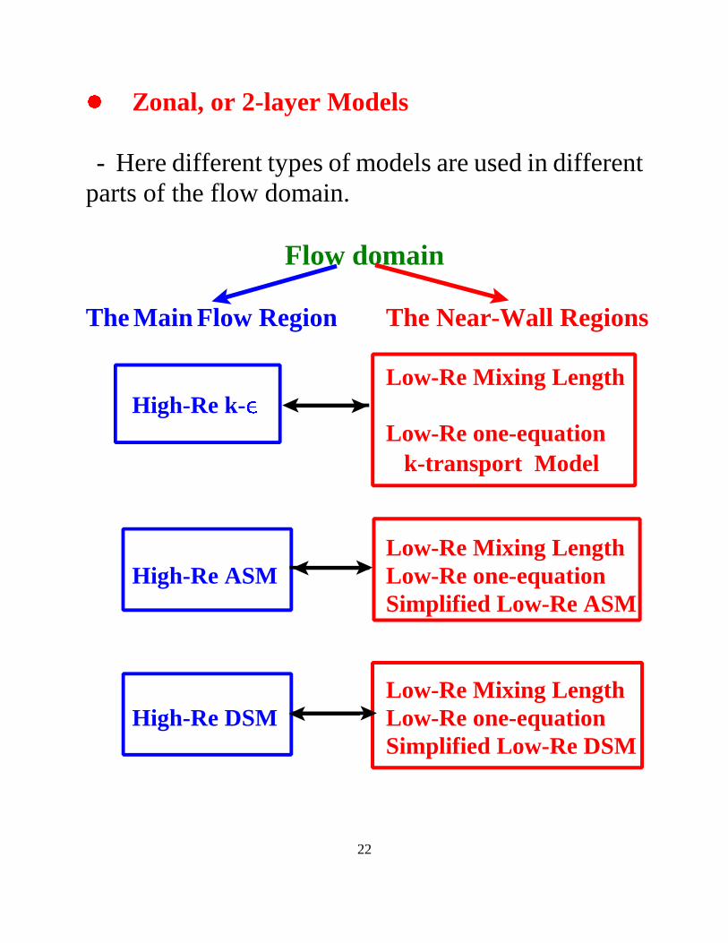
%&Zonal, or 2-layer Models
- Here different types of models are used in differentparts of the flow domain.
Flow domain
The Main Flow Region The Near-Wall Regions
Low-Re Mixing LengthHigh-Re k- '(
Low-Re one-equation k-transpor t Model
Low-Re Mixing LengthHigh-Re ASM Low-Re one-equation
Simpli fied Low-Re ASM
Low-Re Mixing LengthHigh-Re DSM Low-Re one-equation
Simpli fied Low-Re DSM
23
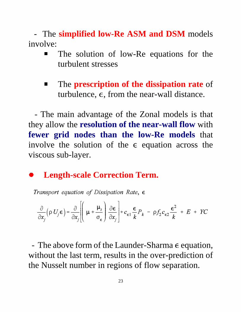
- The simpli fied low-Re ASM and DSM modelsinvolve: ) The solution of low-Re equations for the
turbulent stresses
) The prescription of the dissipation rate ofturbulence, * , from the near-wall distance.
- The main advantage of the Zonal models is thatthey allow the resolution of the near-wall flow withfewer gr id nodes than the low-Re models thatinvolve the solution of the * equation across theviscous sub-layer.
+,Length-scale Correction Term.
- The above form of the Launder-Sharma * equation,without the last term, results in the over-prediction ofthe Nusselt number in regions of f low separation.
24
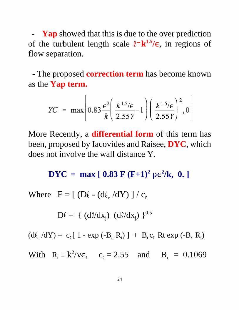
- Yap showed that this is due to the over predictionof the turbulent length scale -. /0 k1.5/ 12 , in regions offlow separation.
- The proposed correction term has become knownas the Yap term.
More Recently, a differential form of this term hasbeen, proposed by Iacovides and Raisee, DYC, whichdoes not involve the wall distance Y.
DYC = max [ 0.83 F (F+1)2 34 56 2/k, 0. ]
Where F = [ (D 7 - (d7 e /dY) ] / c8
D 9 = { (d9 /dxj) (d9 /dxj) }0.5
(d: e /dY) = c; [ 1 - exp (-B < Rt) ] + B < c; Rt exp (-B < Rt)
With Rt = k2/ > ? , c@ = 2.55 and B A = 0.1069
25
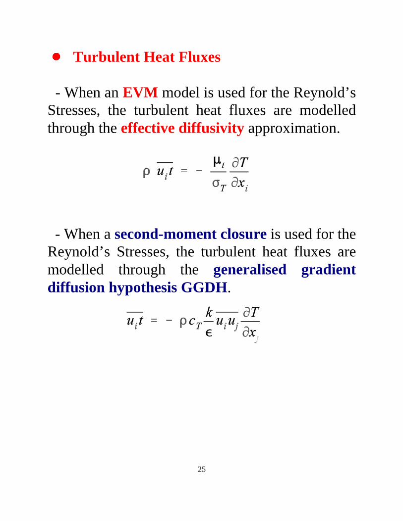
BCTurbulent Heat Fluxes
- When an EVM model is used for the Reynold’sStresses, the turbulent heat fluxes are modelledthrough the effective diffusivity approximation.
- When a second-moment closure is used for theReynold’s Stresses, the turbulent heat fluxes aremodelled through the generalised gradientdiffusion hypothesis GGDH.
26
5. Concluding Remarks
DThe nature of Heat Convection has beendiscussed and the role of turbulence has beenhighlighted.
DThe role of CFD in heat convection analysis hasbeen identified and the and the need forvalidation emphasized.
DThe need for internal cooling of gas-turbineblades has been explained, the main coolingmechanisms have been presented and the complexflow features present in internal cooling passageshave been identified.
DAn overview of the turbulence modelingstrategies tested in our validation studies has alsobeen presented.
DRelevant case studies and resulting conclusionswill be presented in Part II .