Embed Size (px)
Citation preview

Applied Computer Vision 1 Carnegie Mellon University Africa
Applied Computer Vision
David VernonCarnegie Mellon University Africa

Applied Computer Vision 2 Carnegie Mellon University Africa
Lecture 24
3D Vision I
Homogeneous coordinates, perspective projection, camera model and inverse perspective transformation

Applied Computer Vision 3 Carnegie Mellon University Africa
Homogeneous Coordinates
A 3D vector, v = ai + bj + ck, where i, j and k are unit vectors along the X, Y and Z axes is represented in homogenous co-ordinates as
where and
v
xyzw
=
é
ë
êêêê
ù
û
úúúú
axwb
yw
= =, czw
=
Applied Computer Vision 4 Carnegie Mellon University Africa
Homogeneous Coordinates
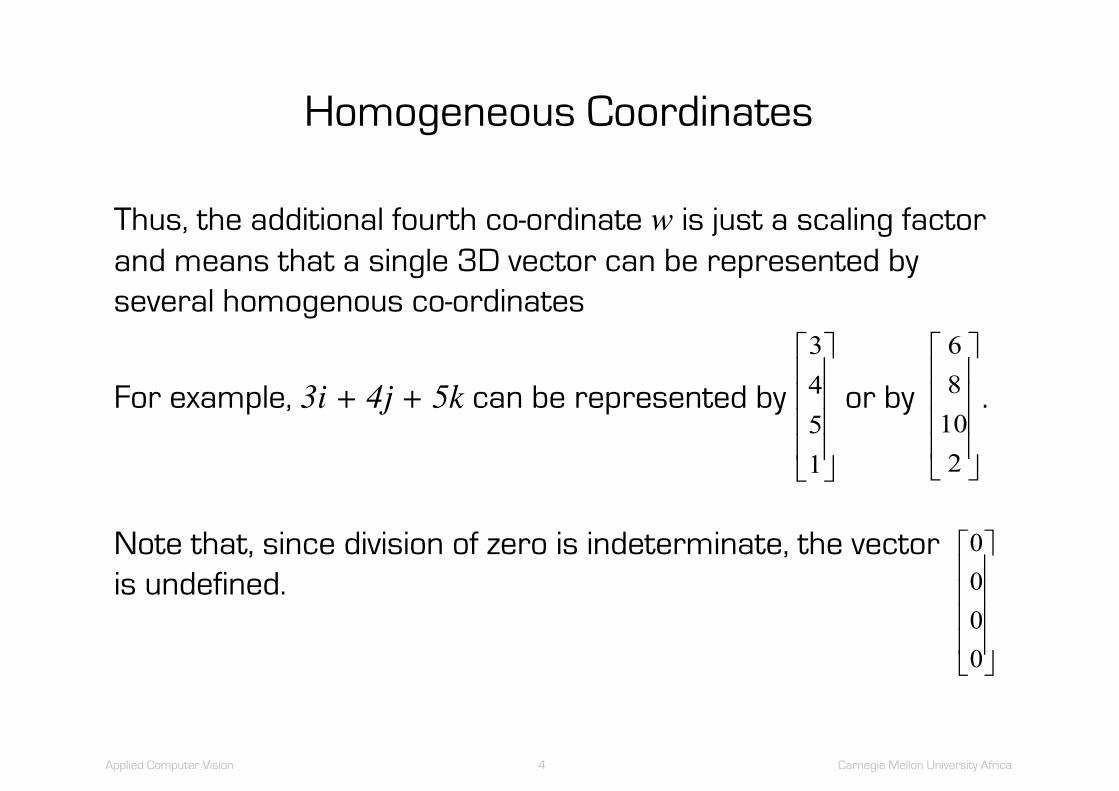
Thus, the additional fourth co-ordinate w is just a scaling factor and means that a single 3D vector can be represented by several homogenous co-ordinates
For example, 3i + 4j + 5k can be represented by or by .
Note that, since division of zero is indeterminate, the vector is undefined.
3451
é
ë
êêêê
ù
û
úúúú
68102
é
ë
êêêê
ù
û
úúúú
0000
é
ë
êêêê
ù
û
úúúú
Applied Computer Vision 5 Carnegie Mellon University Africa
The Camera Model and the Inverse Perspective Transformation
For any given optical configuration, there are two aspects to the relationship between world point and image point
– the camera model, which maps a 3D world point to its corresponding 2D image point
– the inverse perspective transformation, which is used to identify the 3D world point(s) corresponding to a particular 2D image point.

Applied Computer Vision 6 Carnegie Mellon University Africa
The Camera Model and the Inverse Perspective Transformation
Since the imaging process is a projection (from a 3D world to a 2D image), the inverse process, i.e. the inverse perspective transformation, cannot uniquely determine a single world point for a given image point
– the inverse perspective transformation thus maps a 2D image point into a line (an infinite set of points) in the 3D world,
– however, it does so in a useful and well-constrained manner

Applied Computer Vision 7 Carnegie Mellon University Africa
Perspective Projection
Pinhole model of a camera

Applied Computer Vision 8 Carnegie Mellon University Africa
Perspective Projection
Pinhole model of a camera
Source: Markus Vincze, Technische Universität Wien

Applied Computer Vision 9 Carnegie Mellon University Africa
Perspective transformation
http://docs.opencv.org/2.4/modules/calib3d/doc/camera_calibration_and_3d_reconstruction.html

Applied Computer Vision 10 Carnegie Mellon University Africa
The Camera Model and the Inverse Perspective Transformation
For the following, we will assume that the camera model (and, hence, the inverse perspective transformation) is linear
This treatment closely follows that of [Ballard and Brown 1982]

Applied Computer Vision 11 Carnegie Mellon University Africa
The Camera Model
Let the image point in question be given by the co-ordinates which, in homogenous co-ordinates is written .
Thus,
and
UVé
ëê
ù
ûú
uvt
é
ë
êêê
ù
û
úúúU
ut
=
Vvt
=
Applied Computer Vision 12 Carnegie Mellon University Africa
The Camera Model
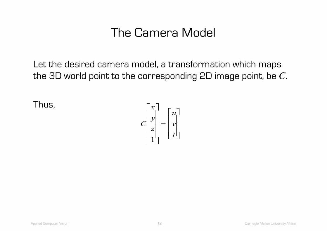
Let the desired camera model, a transformation which maps the 3D world point to the corresponding 2D image point, be C.
Thus,
C
xyz
uvt
1
é
ë
êêêê
ù
û
úúúú
=
é
ë
êêê
ù
û
úúú

Applied Computer Vision 13 Carnegie Mellon University Africa
The Camera Model
Hence C must be a 3*4 (homogenous) transformation
and
CC C C CC C C CC C C C
=
é
ë
êêê
ù
û
úúú
11 12 13 14
21 22 23 24
31 32 33 34
C C C CC C C CC C C C
xyz
uvt
11 12 13 14
21 22 23 24
31 32 33 34 1
é
ë
êêê
ù
û
úúú
é
ë
êêêê
ù
û
úúúú
=
é
ë
êêê
ù
û
úúú

Applied Computer Vision 14 Carnegie Mellon University Africa
The Camera Model
Expanding this matrix equation, we get :
C x C y C z C uC x C x C x C vC x C x C x C t
11 12 13 14
21 22 23 24
31 32 33 34
+ + + =+ + + =+ + + =
(1) (2)
(3)
Applied Computer Vision 15 Carnegie Mellon University Africa
The Camera Model
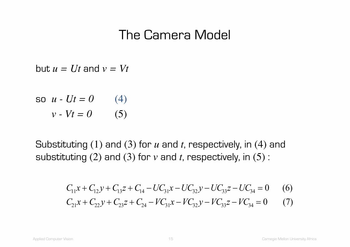
but u = Ut and v = Vt
so u - Ut = 0 (4)v - Vt = 0 (5)
Substituting (1) and (3) for u and t, respectively, in (4) and substituting (2) and (3) for v and t, respectively, in (5) :
C x C y C z C UC x UC y UC z UCC x C y C z C VC x VC y VC z VC
11 12 13 14 31 32 33 34
21 22 23 24 31 32 33 34
00
+ + + - - - - =+ + + - - - - =
(6) (7)

Applied Computer Vision 16 Carnegie Mellon University Africa
The Camera Model
If we establish this association
i.e. if we measure the values of x, y, z, U and V
we will have two equations in which the only unknowns are the twelve camera model coefficients (and which we require)
Since a single observation gives rise to two equations, six observations will produce twelve simultaneous equations which we can solve for the required camera coefficients Cij.

Applied Computer Vision 17 Carnegie Mellon University Africa
The Camera Model
Remember that these two equations arose from the association of a particular world point
and a corresponding image point
xyz1
é
ë
êêêê
ù
û
úúúú
uvt
é
ë
êêê
ù
û
úúú

Applied Computer Vision 18 Carnegie Mellon University Africa
The Camera Model
Before we proceed, however, we need to note that the overall scaling of C is irrelevant due to the homogenous formulation and, thus, the value of C34 may be set arbitrarily to 1 and we can re-write (6) and (7), completing the equations so that terms for each coefficient of C is included, as follows
This reduces the number of unknowns to eleven
C x C y C z C C C C C UC x UC y UC z UC C C C C x C y C z C VC x VC y VC z V11 12 13 14 21 22 23 24 31 32 33
11 12 13 14 21 22 23 24 31 32 33
0 0 0 00 0 0 0+ + + + + + + - - - =+ + + - + + + - - - =

Applied Computer Vision 19 Carnegie Mellon University Africa
The Camera Model
For six observations, we now have twelve equations and eleven unknowns: i.e. the system of equations is over-determined
Re-formulating the twelve equations in matrix form, we can obtain a least-square-error solution to the system using the pseudo-inverse method

Applied Computer Vision 20 Carnegie Mellon University Africa
Let
X
x y z U x U y U zx y z V x V y V z
x y z U x U y U zx y z V x V y V z
x y z U x U y U zx y z V x V y
=
- - -- - -- - -- - -- - -- -
1 1 1 1 1 1 1 1 1
1 1 1 1 1 1 1 1 1
1 1 1 1 1 2 2 2 2
1 1 1 2 2 2 2 2 2
1 1 1 2 2 3 3 3 3
1 1 1 3 3 3 3
1 0 0 0 00 0 0 0 1
1 0 0 0 00 0 0 0 1
1 0 0 0 00 0 0 0 1 -
- - -- - -- - -- - -- - -- -
V zx y z U x U y U z
x y z V x V y V zx y z U x U y U z
x y z V x V y V zx y z U x U y U z
x y z V x V
3 3
1 1 1 4 4 4 4 4 4
1 1 1 4 4 4 4 4 4
1 1 1 5 5 5 5 5 5
1 1 1 5 5 5 5 5 5
1 1 1 6 6 6 6 6 6
1 1 1 6 6
1 0 0 0 00 0 0 0 1
1 0 0 0 00 0 0 0 1
1 0 0 0 00 0 0 0 1 6 6 6 6y V z-
é
ë
êêêêêêêêêêêêêêêêê
ù
û
úúúúúúúúúúúúúúúúú
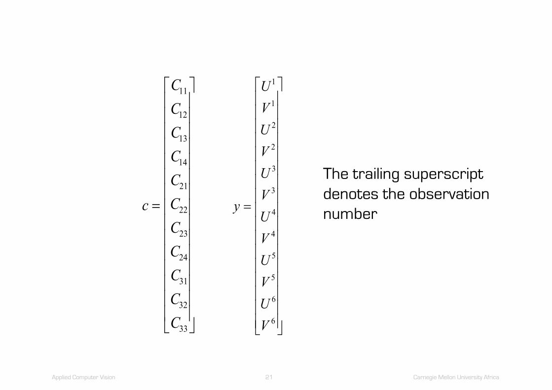
Applied Computer Vision 21 Carnegie Mellon University Africa
c
CCCCCCCCCCC
=
é
ë
êêêêêêêêêêêêêêê
ù
û
úúúúúúúúúúúúúúú
11
12
13
14
21
22
23
24
31
32
33
y
UVUVUVUVUVUV
=
é
ë
êêêêêêêêêêêêêêêêê
ù
û
úúúúúúúúúúúúúúúúú
1
1
2
2
3
3
4
4
5
5
6
6
The trailing superscript denotes the observation number
Applied Computer Vision 22 Carnegie Mellon University Africa
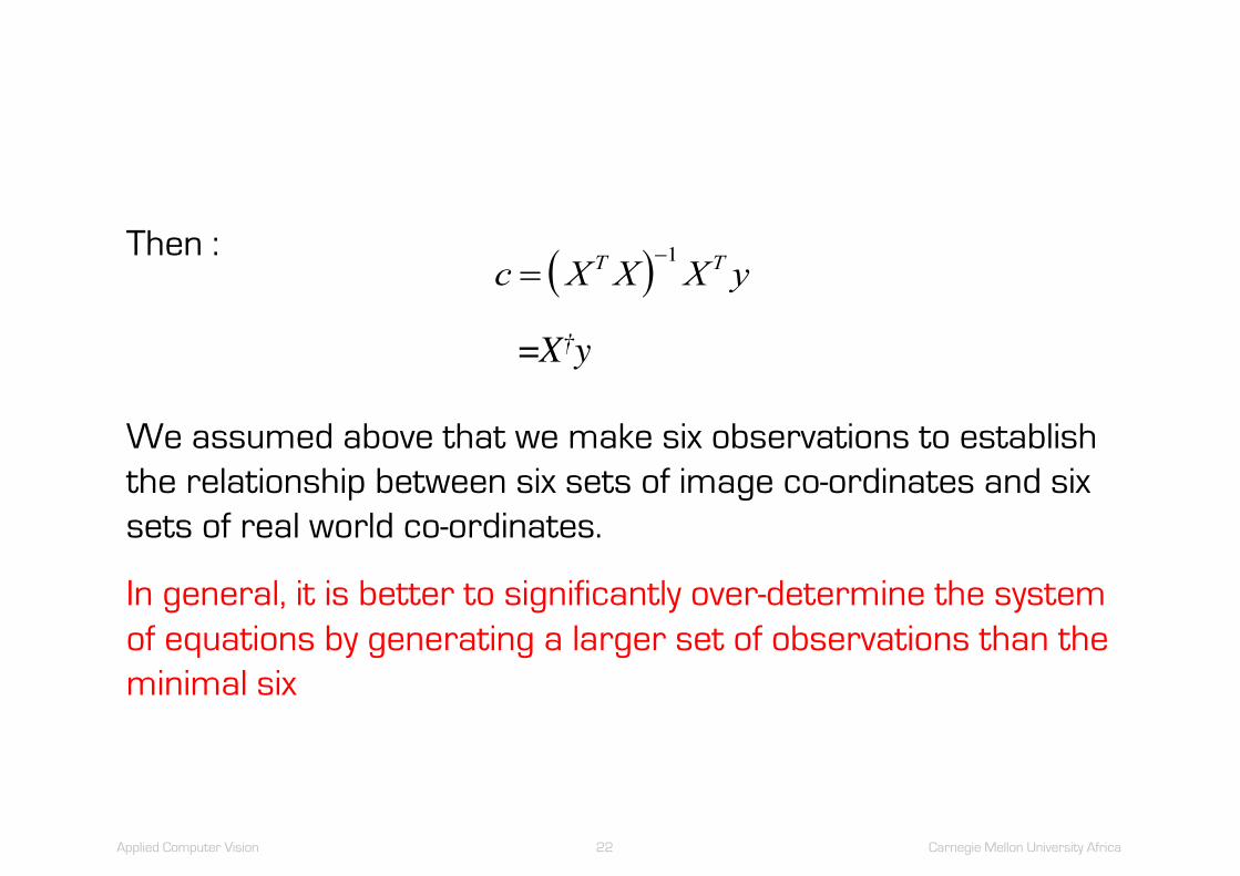
In general, it is better to significantly over-determine the system of equations by generating a larger set of observations than the minimal six
Then :
=X†y
We assumed above that we make six observations to establish the relationship between six sets of image co-ordinates and six sets of real world co-ordinates.
( )c X X X yT T=-1

Applied Computer Vision 23 Carnegie Mellon University Africa
The Camera Model
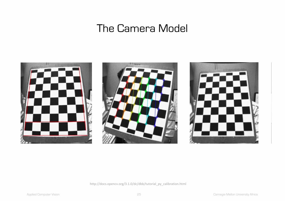
• This is, in fact, the central issue in the derivation of the camera model, that is, the identification of a set of corresponding control points
• There are several approaches.
– we could present the imaging system with a calibration grid
– empirically measure the positions of the grid intersections
– identifying the corresponding points in the image, either interactively or automatically

Applied Computer Vision 24 Carnegie Mellon University Africa
The Camera Model
Applied Computer Vision 25 Carnegie Mellon University Africa
The Camera Model
http://docs.opencv.org/3.1.0/dc/dbb/tutorial_py_calibration.html

Applied Computer Vision 26 Carnegie Mellon University Africa
The Camera Model
http://www.vision.caltech.edu/bouguetj/calib_doc/
• Camera parameters from many planar points– Checkerboard or ellipse patterns on flat plate
• Camera pose from three or more points

Applied Computer Vision 27 Carnegie Mellon University Africa
The Camera Model
• When used for robot manipulation, the empirical measurement of these real-world co-ordinates may be prone to error and this error will be manifested in the resultant camera model
• It is better practice to get the robot itself to calibrate the system
– by fitting it with an end-effector with an accurately located calibration mark (e.g. a cross-hair or a surveyor’s mark)
– by programming it to place the mark at a variety of (known) positions in the field of view of the camera system

Applied Computer Vision 28 Carnegie Mellon University Africa
The Camera Model
Main benefit:
The two components of the manipulation environment,
the robot and the vision system
both of which are reasoning about co-ordinates in the 3D world, are effectively coupled
So, if the vision system “sees” something at a particular location, that is where the robot manipulator will go

Applied Computer Vision 29 Carnegie Mellon University Africa
The Camera Model
So far:
C C C CC C C CC C C C
xyz
uvt
11 12 13 14
21 22 23 24
31 32 33 34 1
é
ë
êêê
ù
û
úúú
é
ë
êêêê
ù
û
úúúú
=
é
ë
êêê
ù
û
úúú

Applied Computer Vision 30 Carnegie Mellon University Africa
The Camera Model
World to camera coordinate
transformationmatrix(4x4)
Perspectiveprojection matrix
(3x4)
Camera to pixel coordinate transformation
matrix (3x3)
=2Dpoint(3x1)
3Dpoint(4x1)
Intrinsic and extrinsic camera parameters
C C C CC C C CC C C C
xyz
uvt
11 12 13 14
21 22 23 24
31 32 33 34 1
é
ë
êêê
ù
û
úúú
é
ë
êêêê
ù
û
úúúú
=
é
ë
êêê
ù
û
úúú
Credit: Markus Vincze, Technische Universität Wien
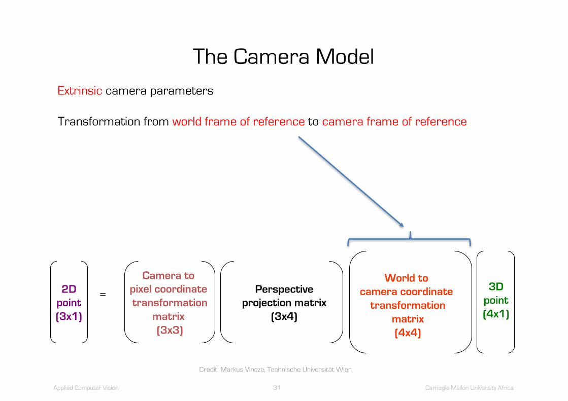
Applied Computer Vision 31 Carnegie Mellon University Africa
The Camera Model
World to camera coordinate
transformationmatrix(4x4)
Perspectiveprojection matrix
(3x4)
Camera to pixel coordinate transformation
matrix (3x3)
=2Dpoint(3x1)
3Dpoint(4x1)
Extrinsic camera parameters
Transformation from world frame of reference to camera frame of reference
Credit: Markus Vincze, Technische Universität Wien

Applied Computer Vision 32 Carnegie Mellon University Africa
The Camera Model
Camera frame
World frame
Credit: Markus Vincze, Technische Universität Wien
Applied Computer Vision 33 Carnegie Mellon University Africa
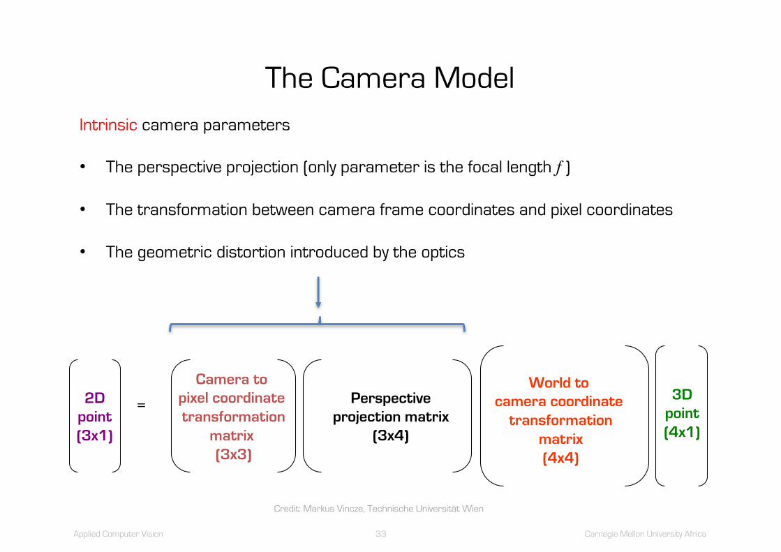
The Camera Model
World to camera coordinate
transformationmatrix(4x4)
Perspectiveprojection matrix
(3x4)
Camera to pixel coordinate transformation
matrix (3x3)
=2Dpoint(3x1)
3Dpoint(4x1)
Intrinsic camera parameters
• The perspective projection (only parameter is the focal length f )
• The transformation between camera frame coordinates and pixel coordinates
• The geometric distortion introduced by the optics
Credit: Markus Vincze, Technische Universität Wien

Applied Computer Vision 34 Carnegie Mellon University Africa
The Camera Model
World to camera coordinate
transformationmatrix(4x4)
Perspectiveprojection matrix
(3x4)
Camera to pixel coordinate transformation
matrix (3x3)
=2Dpoint(3x1)
3Dpoint(4x1)
Perspective Projection
Credit: Markus Vincze, Technische Universität Wien
Applied Computer Vision 35 Carnegie Mellon University Africa
The Camera Model
World to camera coordinate
transformationmatrix(4x4)
Perspectiveprojection matrix
(3x4)
Camera to pixel coordinate transformation
matrix (3x3)
=2Dpoint(3x1)
3Dpoint(4x1)
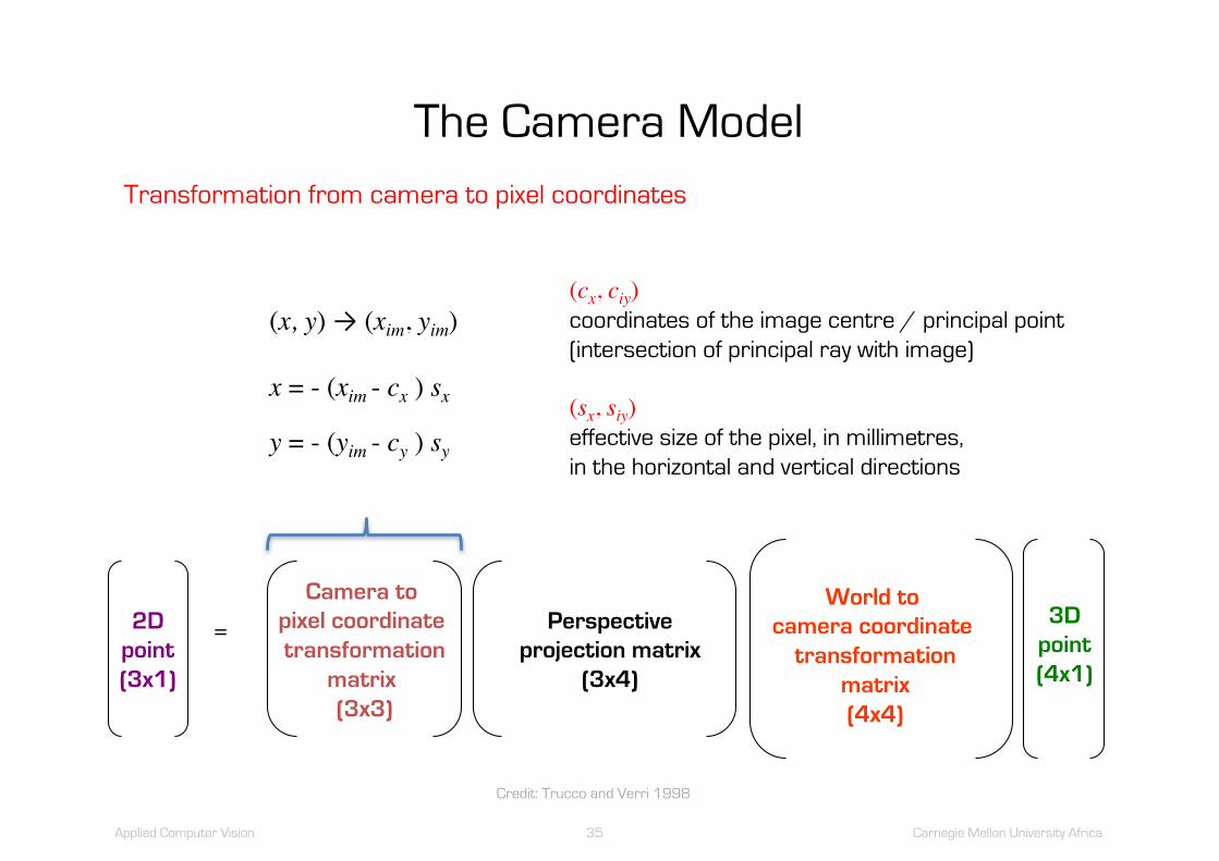
Transformation from camera to pixel coordinates
(x, y) → (xim, yim)
x = - (xim - cx ) sx
y = - (yim - cy ) sy
(cx, ciy)coordinates of the image centre / principal point(intersection of principal ray with image)
(sx, siy)effective size of the pixel, in millimetres, in the horizontal and vertical directions
Credit: Trucco and Verri 1998

Applied Computer Vision 36 Carnegie Mellon University Africa
The Camera Model
World to camera coordinate
transformationmatrix(4x4)
Perspectiveprojection matrix
(3x4)
Camera to pixel coordinate transformation
matrix (3x3)
=2Dpoint(3x1)
3Dpoint(4x1)
Correction of radial distortion
x = xd (1 + k1 r2 + k2 r4 )
y = yd (1 + k1 r2 + k2 r4 )
r2 = xd2 + yd
2
(xd, yd)coordinates of the distorted point
k1 and k2 are further intrinsic parameters
The magnitude of the geometric distortion depends on the quality of the lens
Credit: Trucco and Verri 1998

Applied Computer Vision 37 Carnegie Mellon University Africa
The Camera Model
k1 > 0 k1 < 0
Credit: Markus Vincze, Technische Universität Wien

Applied Computer Vision 38 Carnegie Mellon University Africa
Depth Perception: The Inverse Problem
Estimate depth (3D) of world from images
Inverse perspective transformation
Credit: Markus Vincze, Technische Universität Wien
Applied Computer Vision 39 Carnegie Mellon University Africa
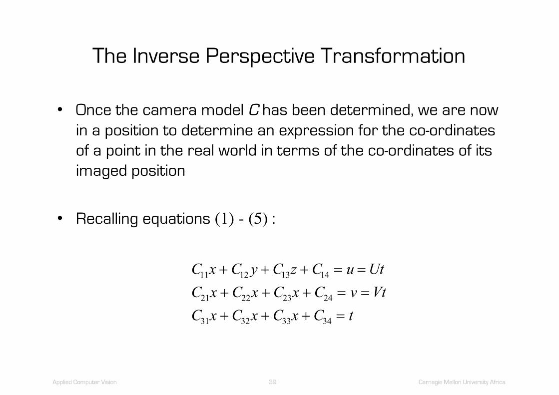
The Inverse Perspective Transformation
• Once the camera model C has been determined, we are now in a position to determine an expression for the co-ordinates of a point in the real world in terms of the co-ordinates of its imaged position
• Recalling equations (1) - (5) :
C x C y C z C u UtC x C x C x C v VtC x C x C x C t
11 12 13 14
21 22 23 24
31 32 33 34
+ + + = =+ + + = =+ + + =

Applied Computer Vision 40 Carnegie Mellon University Africa
The Inverse Perspective Transformation
Substituting the expression for t into the first two equations gives
Hence
( )( )U C x C y C z C C x C x C y C z C
V C x C y C z C C x C x C y C z C31 32 33 34 11 11 12 13 14
31 32 33 34 11 21 22 23 24
+ + + = + + +
+ + + = + + +
( ) ( ) ( ) ( )( ) ( ) ( ) ( )C UC x C UC y C UC z C UC
C VC x C VC y C VC z C VC11 31 12 32 13 33 14 34
21 31 22 32 23 33 24 34
0
0
- + - + - + - =
- + - + - + - =

Applied Computer Vision 41 Carnegie Mellon University Africa
The Inverse Perspective Transformation
Letting
and
we have
a C UCb C UCc C UCd C UC
1 11 31
1 12 32
1 13 33
1 14 34
= -= -= -= -
a C VCb C VCc C VCd C VC
2 21 31
2 22 32
2 23 33
2 24 34
= -= -= -= -
a x b y c z da x b y c z d1 1 1 1
2 2 2 2
00
+ + + =+ + + =

Applied Computer Vision 42 Carnegie Mellon University Africa
The Inverse Perspective Transformation
These are the equations of two planes
The intersection of these planes determines a line comprising the set of real-world points which project onto the image point
Solving these plane equations simultaneously (in terms of z)
UVé
ëê
ù
ûú
( ) ( )( )
( ) ( )( )
xz bc b c b d b d
a b a b
yz a c a c a d a d
a b a b
=- + -
-
=- + -
-
1 2 2 1 1 2 2 1
1 2 2 1
2 1 1 2 2 1 1 2
1 2 2 1

Applied Computer Vision 43 Carnegie Mellon University Africa
The Inverse Perspective Transformation
Thus, for any given z0 , U and V, we may determine the corresponding x0 and y0 , i.e. the real-world co-ordinates
The camera model and the inverse perspective transformation which we have just discussed allow us to compute the x and yreal-world co-ordinates corresponding to a given position in the image
However, we must assume that the z coordinate, i.e. the distance from the camera, is known

Applied Computer Vision 44 Carnegie Mellon University Africa
The Inverse Perspective Transformation
• However, we must assume that the z coordinate, i.e. the distance from the camera, is known
• For some applications, e.g. where objects lie on a table at a given and constant height (i.e. at a given z0), this is sufficient
• In general, however, we will not know the coordinate of the object in the third dimension and we must recover it

Applied Computer Vision 45 Carnegie Mellon University Africa
The Inverse Perspective Transformation
How we can compute z0 ?
– If we have a second image of the scene, taken from another viewpoint
– If we know the image coordinates of the point of interest in this image
– Then we have two camera models and, hence, two inverse perspective transformations
– Instead of solving two plane equations simultaneously, we solve four plane equations

Applied Computer Vision 46 Carnegie Mellon University Africa
The Inverse Perspective Transformation
In particular, we have
where
C1ij and C2ij are the coefficients of the camera model for the first and second images, respectively.U1, V1 and U2, V2 are the co-ordinates of the point of interest in the first and second images, respectively.
a x b y c z da x b y c z dp x q y r z sp x q y r z s
1 1 1 1
2 2 2 2
1 1 1 1
2 2 2 2
0000
+ + + =+ + + =+ + + =+ + + =
a C U Cb C U Cc C U Cd C U Cp C U Cq C U Cr C U Cs C U C
1 11 31
1 12 32
1 13 33
1 14 34
1 11 31
1 12 32
1 13 33
1 14 34
1 1 11 1 11 1 11 1 12 2 22 2 22 2 22 2 2
= -= -= -= -= -= -= -= -
a C V Cb C V Cc C V Cd C V Cp C V Cq C V Cr C V Cs C V C
2 21 31
2 22 32
2 23 33
2 24 34
2 21 31
2 22 32
2 23 33
2 24 34
1 1 11 1 11 1 11 1 12 2 22 2 22 2 22 2 2
= -= -= -= -= -= -= -= -

Applied Computer Vision 47 Carnegie Mellon University Africa
The Inverse Perspective Transformation
Since we now have four equations and three unknowns,
the system is over-determined
So, we compute a least-square-error solution using the pseudo-inverse technique

Applied Computer Vision 48 Carnegie Mellon University Africa
The Inverse Perspective Transformation
• It should be noted that the key here is not so much the mathematics which allows us to compute x0 , y0 and z0but, rather, the image analysis by which we identify the corresponding point of interest in the two images
• It is this correspondence problem which lies at the heart of most of the difficulties in recovery of depth information

Applied Computer Vision 49 Carnegie Mellon University Africa
The Inverse Perspective Transformation
[Young]
Credit: Markus Vincze, Technische Universität Wien
Applied Computer Vision 50 Carnegie Mellon University Africa
Demos
The following code is taken from the cameraCalibration project
in the lectures directory of the ACV repository
See:
cameraCalibration.h
cameraCalibrationImplementation.cpp
cameraCalibrationApplication.cpp

Applied Computer Vision 51 Carnegie Mellon University Africa
Reading
R. Szeliski, Computer Vision: Algorithms and Applications, Springer, 2010.
Section 2.1.5 3D to 2D projections
Section 6.3 Geometric intrinsic calibration
Vernon, D. 1991. Machine Vision: Automated Visual Inspection and Robot Vision, Prentice-Hall
International; Section 8.6
Dawson-Howe, K. and Vernon, D. 1995. "Simple Pinhole Camera Calibration", The International
Journal of Imaging Systems and Technology, Vol. 5, No. 1, pp. 1-6, Wiley, UK.
OpenCV documentation on camera calibration:
http://docs.opencv.org/2.4/modules/calib3d/doc/camera_calibration_and_3d_reconstruction.html