Embed Size (px)
Citation preview
Applying Model Based Systems Engineering to
NASA’s Space Communications Networks
Kul Bhasin, Patrick Barnes, Jessica Reinert, Bert Golden
National Aeronautics Space Administration
Glenn Research Center
Cleveland, Ohio
Abstract—System engineering practices for
complex systems and networks now require that
requirement, architecture, and concept of
operations product development teams,
simultaneously harmonize their activities to
provide timely, useful and cost-effective products.
When dealing with complex systems of systems,
traditional systems engineering methodology
quickly falls short of achieving project objectives.
This approach is encumbered by the use of a
number of disparate hardware and software tools,
spreadsheets and documents to grasp the concept
of the network design and operation. In case of
NASA’s space communication networks, since the
networks are geographically distributed, and so
are its subject matter experts, the team is
challenged to create a common language and tools
to produce its products. Using Model Based
Systems Engineering methods and tools allows for
a unified representation of the system in a model
that enables a highly related level of detail. To
date, Program System Engineering (PSE) team
has been able to model each network from their
top-level operational activities and system
functions down to the atomic level through
relational modeling decomposition. These models
allow for a better understanding of the
relationships between NASA’s stakeholders,
internal organizations, and impacts to all related
entities due to integration and sustainment of
existing systems.
Understanding the existing systems is
essential to accurate and detailed study of
integration options being considered. In this
paper, we identify the challenges the PSE team
faced in its quest to unify complex legacy space
communications networks and their operational
processes. We describe the initial approaches
undertaken and the evolution toward model based
system engineering applied to produce Space
Communication and Navigation (SCaN) PSE
products. We will demonstrate the practice of
Model Based System Engineering applied to
integrating space communication networks and
the summary of its results and impact. We will
highlight the insights gained by applying the
Model Based System Engineering and provide
recommendations for its applications and
improvements.
Keywords— NASA, Model Based Systems
Engineering, Space Communications, Ground
Network Integration
I. INTRODUCTION
In 2006, NASA administration mandated the
centralization of the management of NASA’s Space
Communications and Navigation (SCaN) networks:
the Near Earth Network (NEN), the Space Network
(SN), and the Deep Space Network (DSN).
Currently, these networks provide communication
and tracking services to user missions through NASA
SCaN Program [1]. The networks have evolved over
a number of years and have utilized the technologies
available during the implementation and upgrade
periods. The recent developments in hardware and
software technologies have the potential to integrate
the current configuration of loosely coupled networks
into a single, unified, integrated network while
providing savings in lifecycle costs. An Integrated
Network Architecture (INA) trade study team was
established and comprised members with diverse
skill sets from various networks system engineering
organizations. The INA team studied various options
on the integration of the networks and has
summarized its finding elsewhere [2]. Initially they
used document based system engineering. It was used
to document information and as well as create models
of architecture concepts. Data was stored in a
common repository accessible by INA team
members. The process was characterized by the
generation of text-based specifications and design
documents, in hardcopy or electronic file format, that
are then exchanged between customers, users,
developers and testers [1]. Emphasis was placed on
controlling the documentation and ensuring it is
valid, complete, and consistent and that the
developed system complies with the documentation.
https://ntrs.nasa.gov/search.jsp?R=20130013600 2018-02-12T23:12:26+00:00Z
Because the information was spread across
multiple documents, the completeness, consistency
and relationships among requirements, design,
engineering analysis, and test information could be
difficult to assess. The INA team found it difficult to
understand particular aspects of the networks to
perform traceability and change impact assessments.
It became difficult to maintain or reuse the system
requirements and design information for an evolving
integrated network high-level architecture design and
operations. They then embarked on applying the
Model Based System Engineering (MBSE) to its
trade options analysis for the development of INA.
The following sections describe the approach
taken to set up the MBSE methodology. Then the
details of the use of document based systems
engineering, transition and application of MBSE to
the trade study analysis of the INA. We discuss the
current status and present the conclusion.
II. ESTABLISHING THE MODEL BASED
ENGINEERING METHODOLOGY
The use of MBSE started with the rendering of
the legacy network architectures and operations since
the network were designed and implemented in the
era of meager documentation, much of which was no
longer available. However, the tool being used to
develop the architecture was not found suitable for
the INA trade study work because the tool required
updates to individual diagrams rather than allowing
an element to be updated and having all the diagrams
updated simultaneously which resulted in significant
rework for even small architecture changes. A small
trade study was conducted [3] to determine the
MBSE tool that would be used. Several tools were
evaluated for applying MBSE to study and develop
the INA. These tools comprised of MagicDraw,
Rhapsody, Enterprise Architect, CORE, DOORS,
CRADLE and Artisan Studio. The tool identified was
No Magic’s MagicDraw. The INA team was trained
and the modelers were charged to decide what
framework/language to use. The modelers started
off using Department of Defense Architecture
Framework (DoDAF) views [4] but eventually
migrated to SysML [5] in favor of a less constrained
modeling environment.
MBSE requires upfront investment in tools
and training. Document based practices were
supported while establishing the new MBSE
processes to perform system engineering functions.
Several modeling methodologies and languages such
UML2 – Unified Modeling Language 2 (Software
Engineers), SysML – System Modeling Language
(Systems Engineers), AADL – Architecture Analysis
and Design Language (Society of Automotive
Engineers), BPMN/UML – Business Process
Modeling Notation/Unified Modeling Language
(Business Analysts) were reviewed.
III. IMPLEMENTING MBSE FOR SPACE
COMMUNICATION NETWORK INTEGRATION
The INA team started out documenting the three
NASA space communication networks based on the
DoDAF using Microsoft office tools. The same tools
were used to produce the INA options and that is
when they begin to notice the need for the MBSE.
Although, this approach provided an introduction to
existing Networks for those working on integration
activities, some of the INA team members started
working on the implementation of MBSE to better
quantify potential benefits of its use. Below are the
details of these steps which also include how MBSE
was finally applied to the INA trade studies.
A. Documenting the Integrated Network
Architecture
The INA team’s first step was to examine the
current opertional processes and software systems of
the Operational Networks. The INA team, with the
ultimate goal of designing an integrated (“To-Be”)
architecture for the network, needed to understand
the details of each operational network. To do so,
network characteristics were tracked in vast
spreadsheets, terminology and definitions were put
into excel format and discussed at length, “as-is”
PowerPoint diagrams were created; all to better
understand the characteristics of the networks.
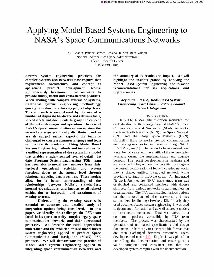
While Microsoft PowerPoint was used to create
architecture diagrams for presentation (see Fig. 1), it
lacks the ability to create levels of archtiecture
information, reuse of elements throughout seveal
diagrams, and maintains a single data element
repository, to mention a few short comings. The
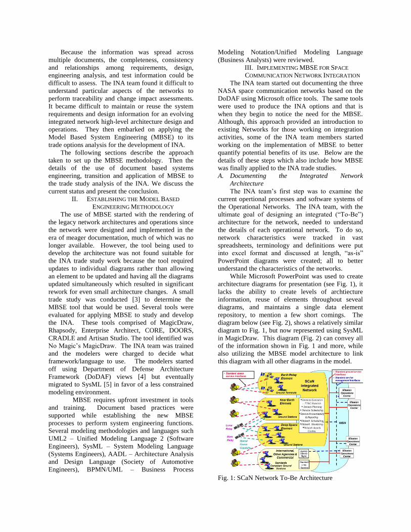
diagram below (see Fig. 2), shows a relatively similar
diagram to Fig. 1, but now represented using SysML
in MagicDraw. This diagram (Fig. 2) can convey all
of the information shown in Fig. 1 and more, while
also utilizing the MBSE model architecture to link
this diagram with all other diagrams in the model.
Fig. 1: SCaN Network To-Be Architecture
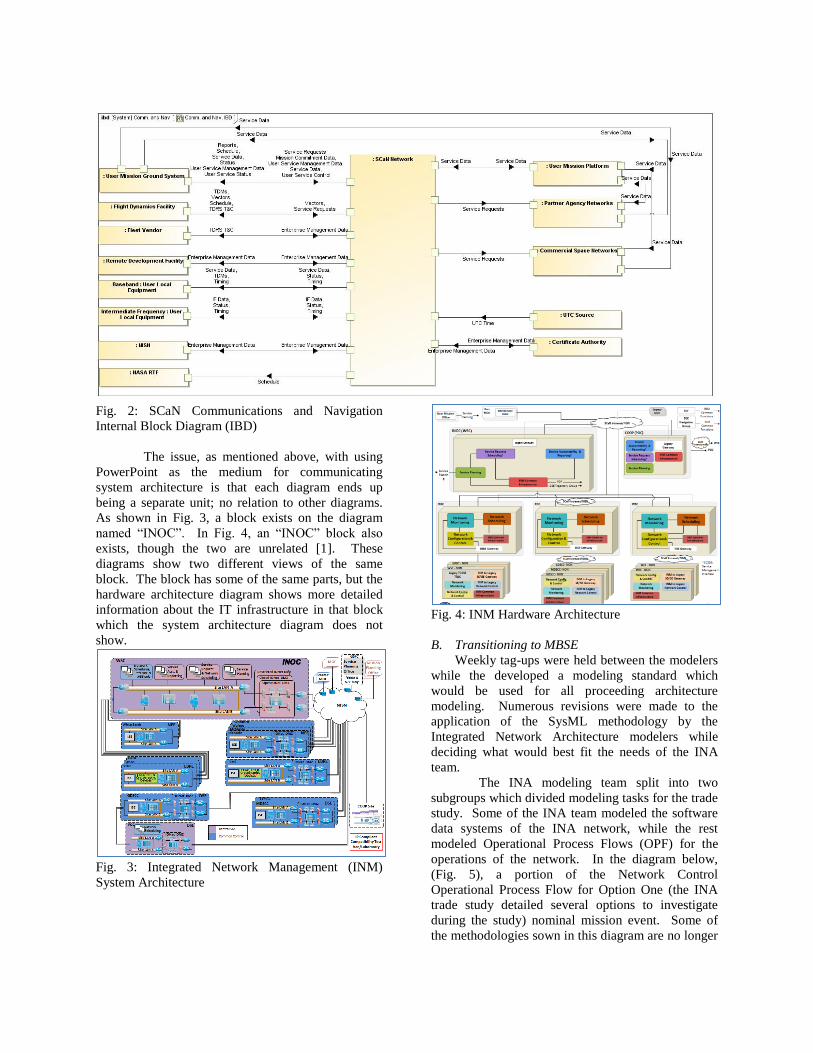
Fig. 2: SCaN Communications and Navigation
Internal Block Diagram (IBD)
The issue, as mentioned above, with using
PowerPoint as the medium for communicating
system architecture is that each diagram ends up
being a separate unit; no relation to other diagrams.
As shown in Fig. 3, a block exists on the diagram
named “INOC”. In Fig. 4, an “INOC” block also
exists, though the two are unrelated [1]. These
diagrams show two different views of the same
block. The block has some of the same parts, but the
hardware architecture diagram shows more detailed
information about the IT infrastructure in that block
which the system architecture diagram does not
show.
Fig. 3: Integrated Network Management (INM)
System Architecture
Fig. 4: INM Hardware Architecture
B. Transitioning to MBSE
Weekly tag-ups were held between the modelers
while the developed a modeling standard which
would be used for all proceeding architecture
modeling. Numerous revisions were made to the
application of the SysML methodology by the
Integrated Network Architecture modelers while
deciding what would best fit the needs of the INA
team.
The INA modeling team split into two
subgroups which divided modeling tasks for the trade
study. Some of the INA team modeled the software
data systems of the INA network, while the rest
modeled Operational Process Flows (OPF) for the
operations of the network. In the diagram below,
(Fig. 5), a portion of the Network Control
Operational Process Flow for Option One (the INA
trade study detailed several options to investigate
during the study) nominal mission event. Some of
the methodologies sown in this diagram are no longer
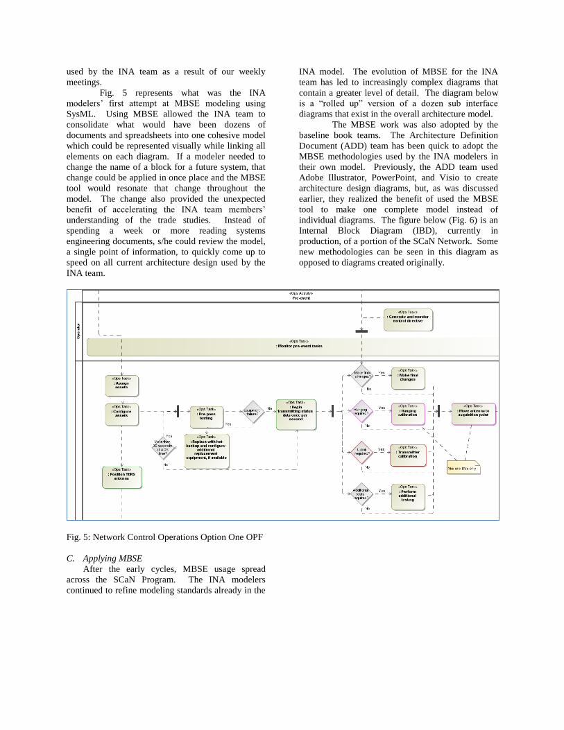
used by the INA team as a result of our weekly
meetings.
Fig. 5 represents what was the INA
modelers’ first attempt at MBSE modeling using
SysML. Using MBSE allowed the INA team to
consolidate what would have been dozens of
documents and spreadsheets into one cohesive model
which could be represented visually while linking all
elements on each diagram. If a modeler needed to
change the name of a block for a future system, that
change could be applied in once place and the MBSE
tool would resonate that change throughout the
model. The change also provided the unexpected
benefit of accelerating the INA team members’
understanding of the trade studies. Instead of
spending a week or more reading systems
engineering documents, s/he could review the model,
a single point of information, to quickly come up to
speed on all current architecture design used by the
INA team.
Fig. 5: Network Control Operations Option One OPF
C. Applying MBSE
After the early cycles, MBSE usage spread
across the SCaN Program. The INA modelers
continued to refine modeling standards already in the
INA model. The evolution of MBSE for the INA
team has led to increasingly complex diagrams that
contain a greater level of detail. The diagram below
is a “rolled up” version of a dozen sub interface
diagrams that exist in the overall architecture model.
The MBSE work was also adopted by the
baseline book teams. The Architecture Definition
Document (ADD) team has been quick to adopt the
MBSE methodologies used by the INA modelers in
their own model. Previously, the ADD team used
Adobe Illustrator, PowerPoint, and Visio to create
architecture design diagrams, but, as was discussed
earlier, they realized the benefit of used the MBSE
tool to make one complete model instead of
individual diagrams. The figure below (Fig. 6) is an
Internal Block Diagram (IBD), currently in
production, of a portion of the SCaN Network. Some
new methodologies can be seen in this diagram as
opposed to diagrams created originally.
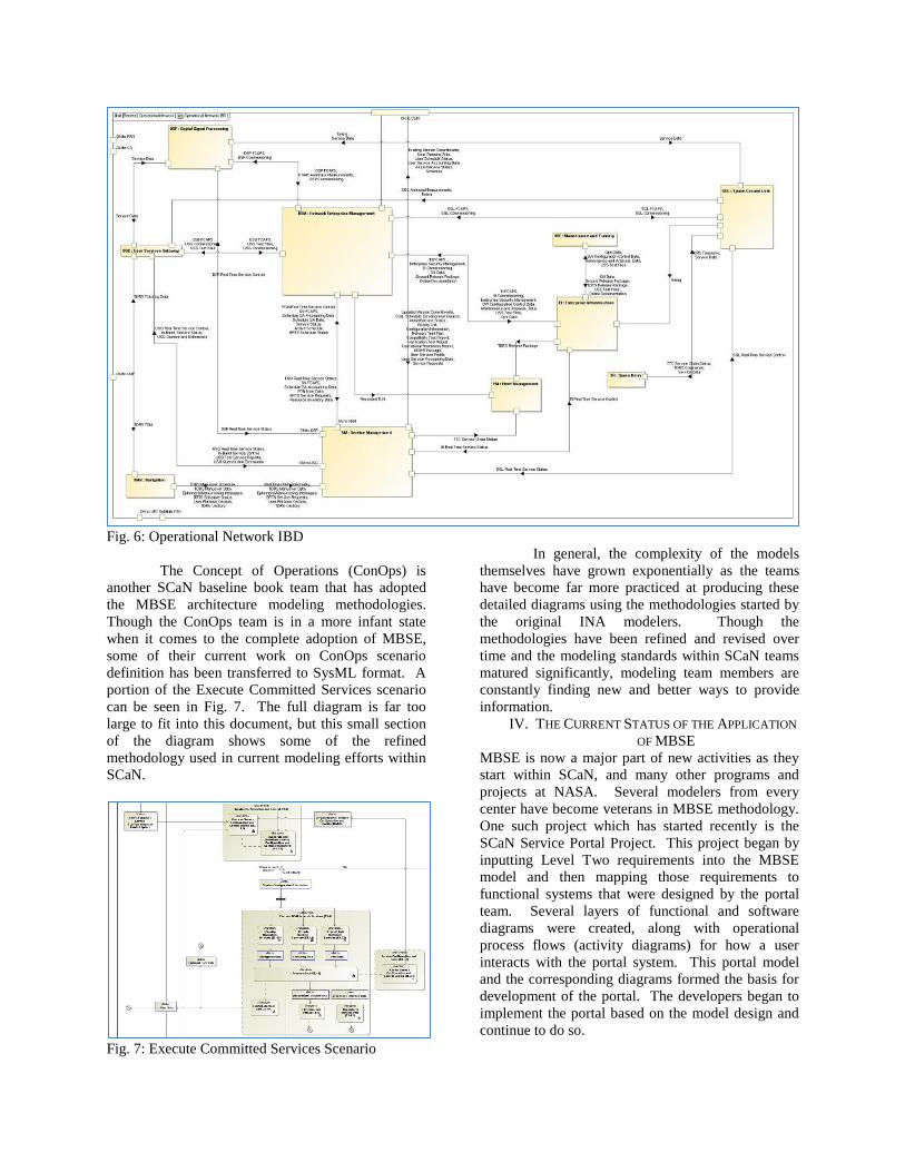
Fig. 6: Operational Network IBD
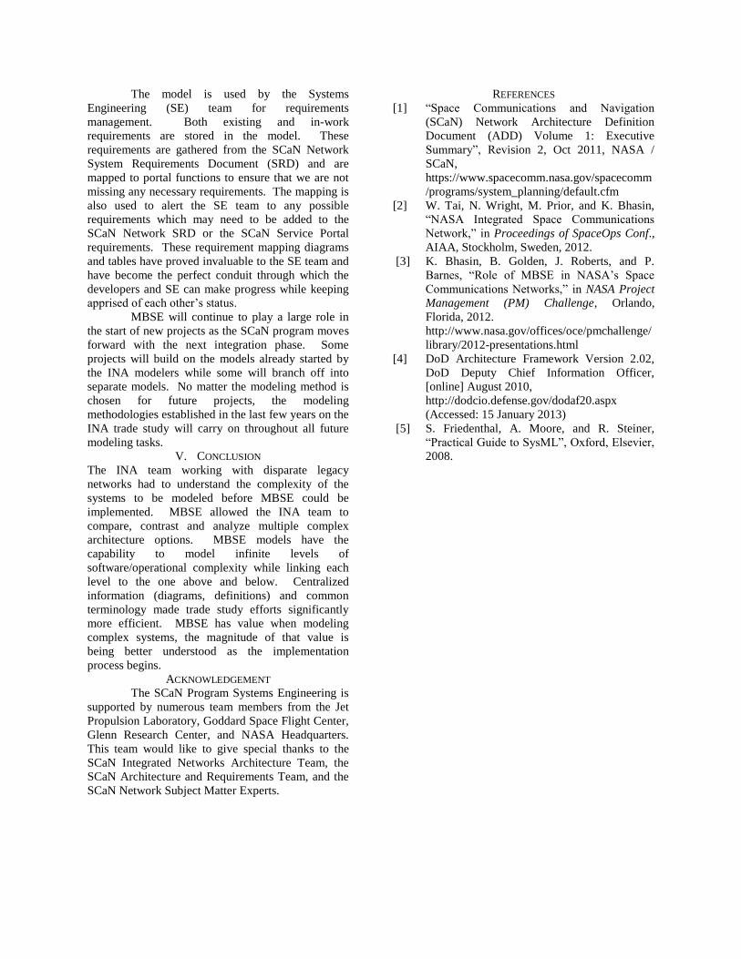
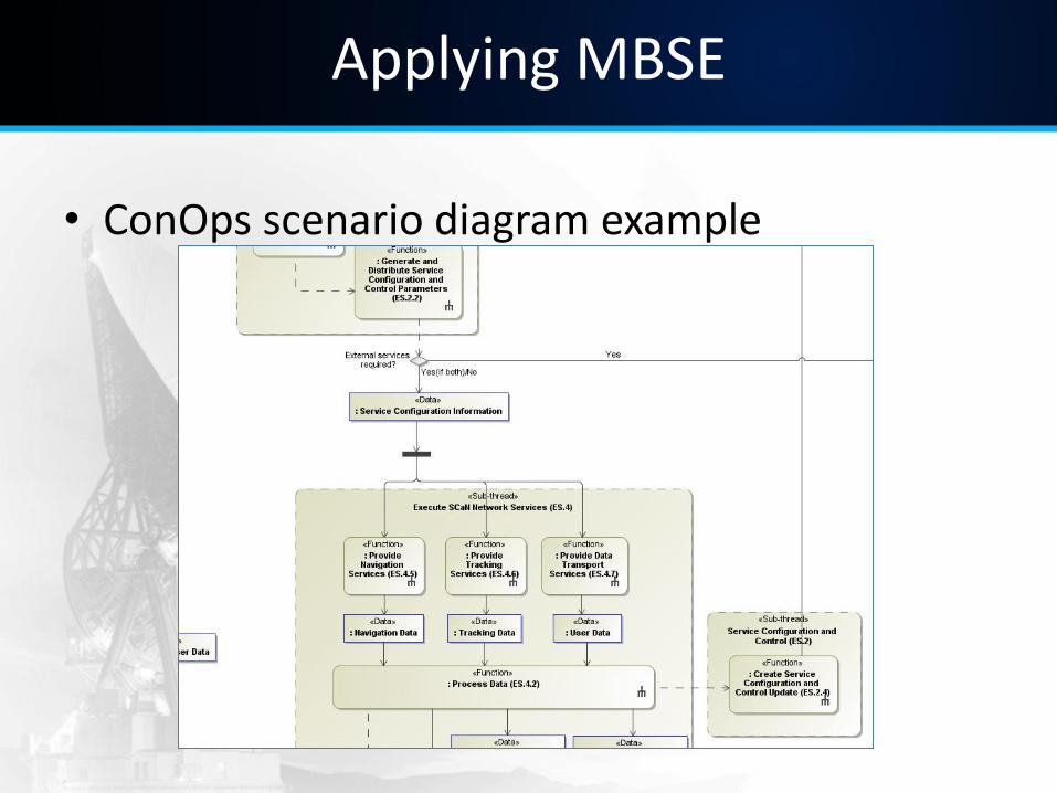
The Concept of Operations (ConOps) is
another SCaN baseline book team that has adopted
the MBSE architecture modeling methodologies.
Though the ConOps team is in a more infant state
when it comes to the complete adoption of MBSE,
some of their current work on ConOps scenario
definition has been transferred to SysML format. A
portion of the Execute Committed Services scenario
can be seen in Fig. 7. The full diagram is far too
large to fit into this document, but this small section
of the diagram shows some of the refined
methodology used in current modeling efforts within
SCaN.
Fig. 7: Execute Committed Services Scenario
In general, the complexity of the models
themselves have grown exponentially as the teams
have become far more practiced at producing these
detailed diagrams using the methodologies started by
the original INA modelers. Though the
methodologies have been refined and revised over
time and the modeling standards within SCaN teams
matured significantly, modeling team members are
constantly finding new and better ways to provide
information.
IV. THE CURRENT STATUS OF THE APPLICATION
OF MBSE
MBSE is now a major part of new activities as they
start within SCaN, and many other programs and
projects at NASA. Several modelers from every
center have become veterans in MBSE methodology.
One such project which has started recently is the
SCaN Service Portal Project. This project began by
inputting Level Two requirements into the MBSE
model and then mapping those requirements to
functional systems that were designed by the portal
team. Several layers of functional and software
diagrams were created, along with operational
process flows (activity diagrams) for how a user
interacts with the portal system. This portal model
and the corresponding diagrams formed the basis for
development of the portal. The developers began to
implement the portal based on the model design and
continue to do so.
The model is used by the Systems
Engineering (SE) team for requirements
management. Both existing and in-work
requirements are stored in the model. These
requirements are gathered from the SCaN Network
System Requirements Document (SRD) and are
mapped to portal functions to ensure that we are not
missing any necessary requirements. The mapping is
also used to alert the SE team to any possible
requirements which may need to be added to the
SCaN Network SRD or the SCaN Service Portal
requirements. These requirement mapping diagrams
and tables have proved invaluable to the SE team and
have become the perfect conduit through which the
developers and SE can make progress while keeping
apprised of each other’s status.
MBSE will continue to play a large role in
the start of new projects as the SCaN program moves
forward with the next integration phase. Some
projects will build on the models already started by
the INA modelers while some will branch off into
separate models. No matter the modeling method is
chosen for future projects, the modeling
methodologies established in the last few years on the
INA trade study will carry on throughout all future
modeling tasks.
V. CONCLUSION
The INA team working with disparate legacy
networks had to understand the complexity of the
systems to be modeled before MBSE could be
implemented. MBSE allowed the INA team to
compare, contrast and analyze multiple complex
architecture options. MBSE models have the
capability to model infinite levels of
software/operational complexity while linking each
level to the one above and below. Centralized
information (diagrams, definitions) and common
terminology made trade study efforts significantly
more efficient. MBSE has value when modeling
complex systems, the magnitude of that value is
being better understood as the implementation
process begins.
ACKNOWLEDGEMENT
The SCaN Program Systems Engineering is
supported by numerous team members from the Jet
Propulsion Laboratory, Goddard Space Flight Center,
Glenn Research Center, and NASA Headquarters.
This team would like to give special thanks to the
SCaN Integrated Networks Architecture Team, the
SCaN Architecture and Requirements Team, and the
SCaN Network Subject Matter Experts.
REFERENCES
[1] “Space Communications and Navigation
(SCaN) Network Architecture Definition
Document (ADD) Volume 1: Executive
Summary”, Revision 2, Oct 2011, NASA /
SCaN,
https://www.spacecomm.nasa.gov/spacecomm
/programs/system_planning/default.cfm
[2] W. Tai, N. Wright, M. Prior, and K. Bhasin,
“NASA Integrated Space Communications
Network,” in Proceedings of SpaceOps Conf.,
AIAA, Stockholm, Sweden, 2012.
[3] K. Bhasin, B. Golden, J. Roberts, and P.
Barnes, “Role of MBSE in NASA’s Space
Communications Networks,” in NASA Project
Management (PM) Challenge, Orlando,
Florida, 2012.
http://www.nasa.gov/offices/oce/pmchallenge/
library/2012-presentations.html
[4] DoD Architecture Framework Version 2.02,
DoD Deputy Chief Information Officer,
[online] August 2010,
http://dodcio.defense.gov/dodaf20.aspx
(Accessed: 15 January 2013)
[5] S. Friedenthal, A. Moore, and R. Steiner,
“Practical Guide to SysML”, Oxford, Elsevier,
2008.

1
Applying Model Based Systems Engineering to NASA’s Space Communications Networks
IEEE SysCon 2013 April 15th – 18th, 2013
Kul Bhasin, Patrick Barnes, Jessica Reinert, Bert Golden Glenn Research Center
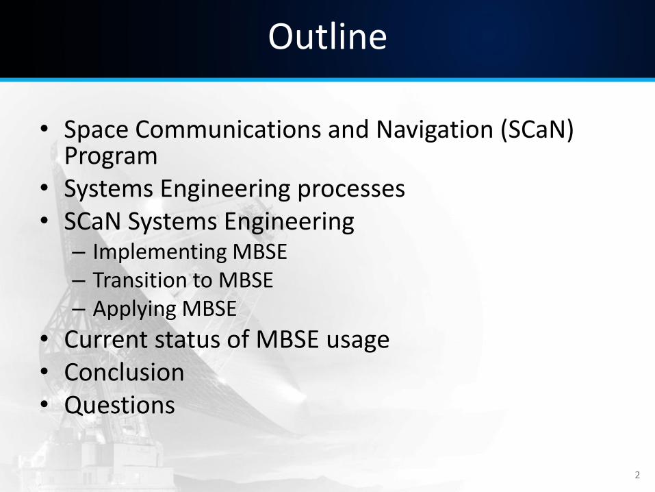
Outline
• Space Communications and Navigation (SCaN) Program
• Systems Engineering processes • SCaN Systems Engineering
– Implementing MBSE – Transition to MBSE – Applying MBSE
• Current status of MBSE usage • Conclusion • Questions
2
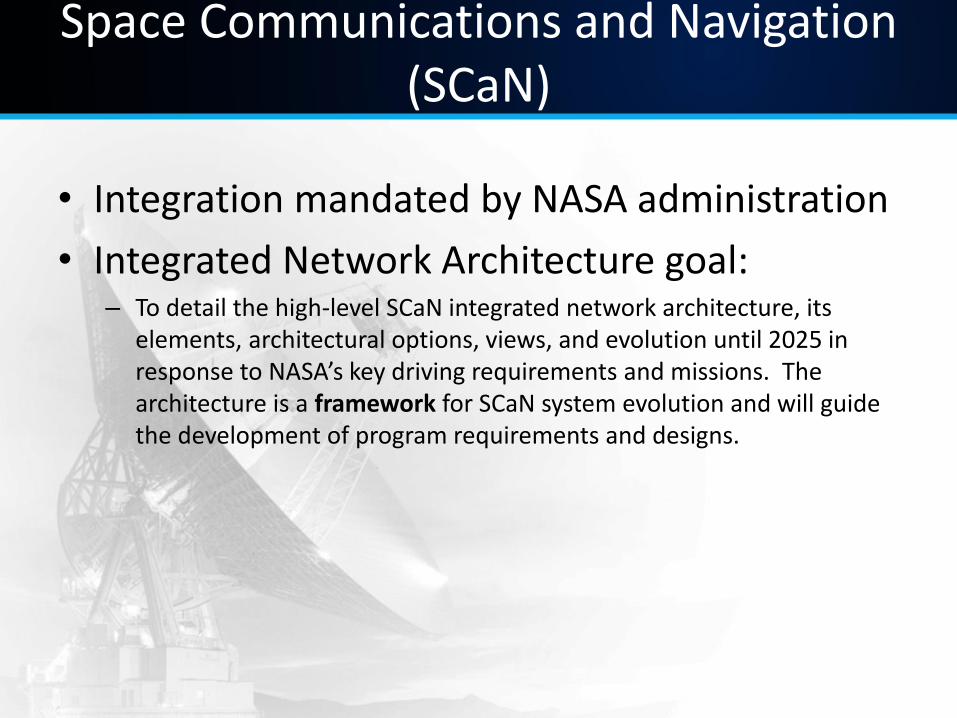
Space Communications and Navigation (SCaN)
• Integration mandated by NASA administration
• Integrated Network Architecture goal: – To detail the high-level SCaN integrated network architecture, its
elements, architectural options, views, and evolution until 2025 in response to NASA’s key driving requirements and missions. The architecture is a framework for SCaN system evolution and will guide the development of program requirements and designs.
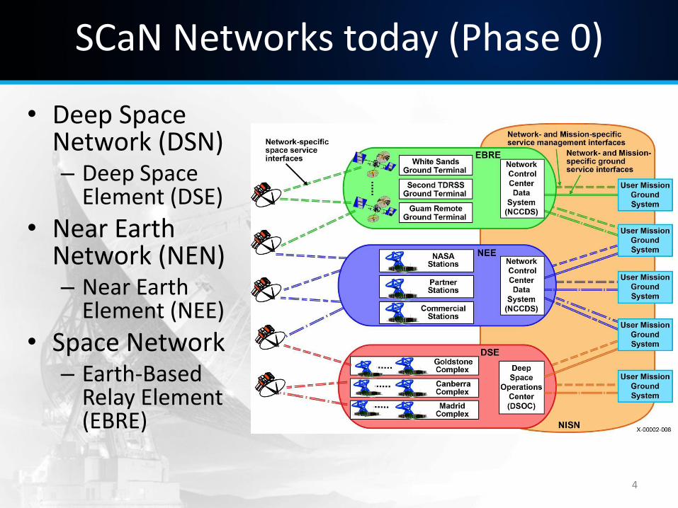
SCaN Networks today (Phase 0)
• Deep Space Network (DSN) – Deep Space
Element (DSE)
• Near Earth Network (NEN) – Near Earth
Element (NEE)
• Space Network – Earth-Based
Relay Element (EBRE)
4
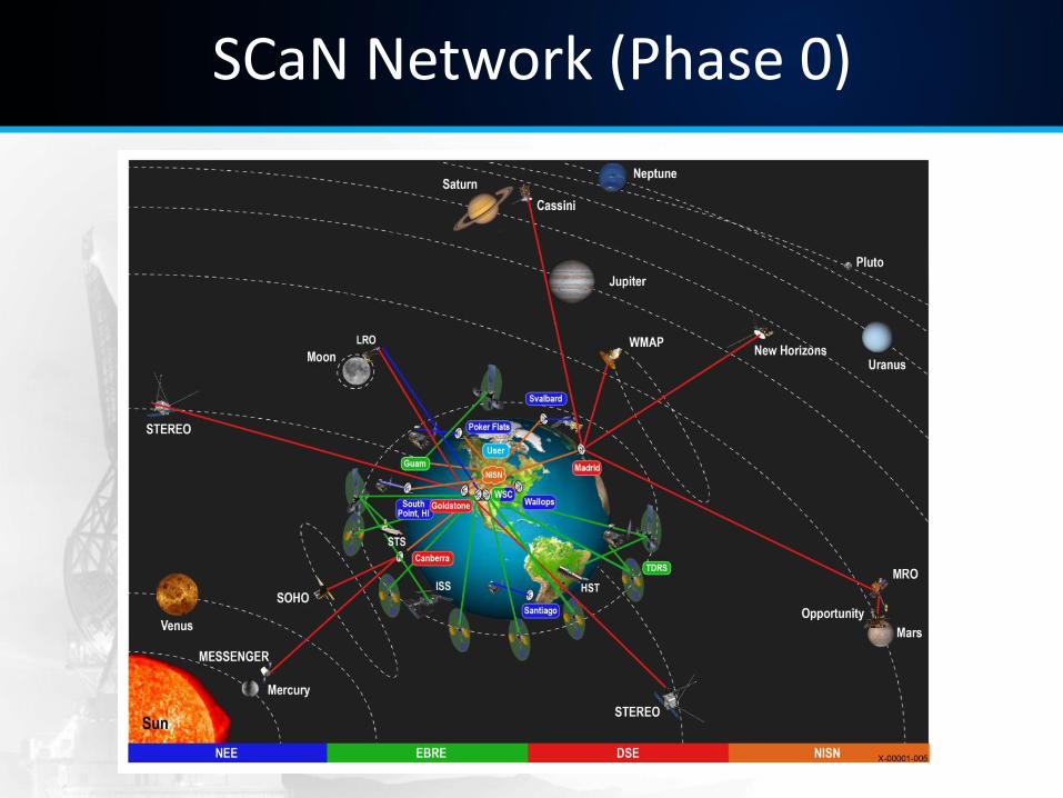
SCaN Network (Phase 0)
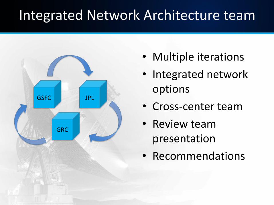
Integrated Network Architecture team
• Multiple iterations
• Integrated network options
• Cross-center team
• Review team presentation
• Recommendations
GSFC JPL
GRC
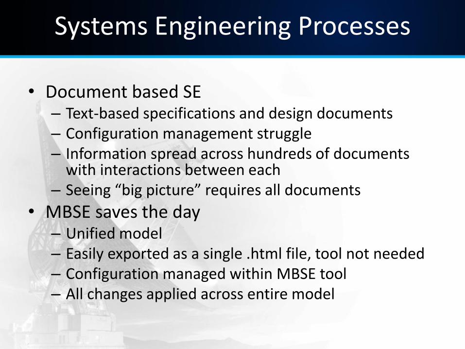
Systems Engineering Processes
• Document based SE – Text-based specifications and design documents – Configuration management struggle – Information spread across hundreds of documents
with interactions between each – Seeing “big picture” requires all documents
• MBSE saves the day – Unified model – Easily exported as a single .html file, tool not needed – Configuration managed within MBSE tool – All changes applied across entire model
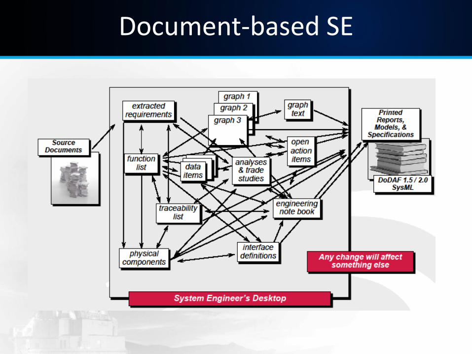
Document-based SE
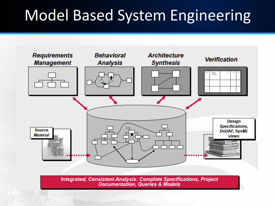
Model Based System Engineering
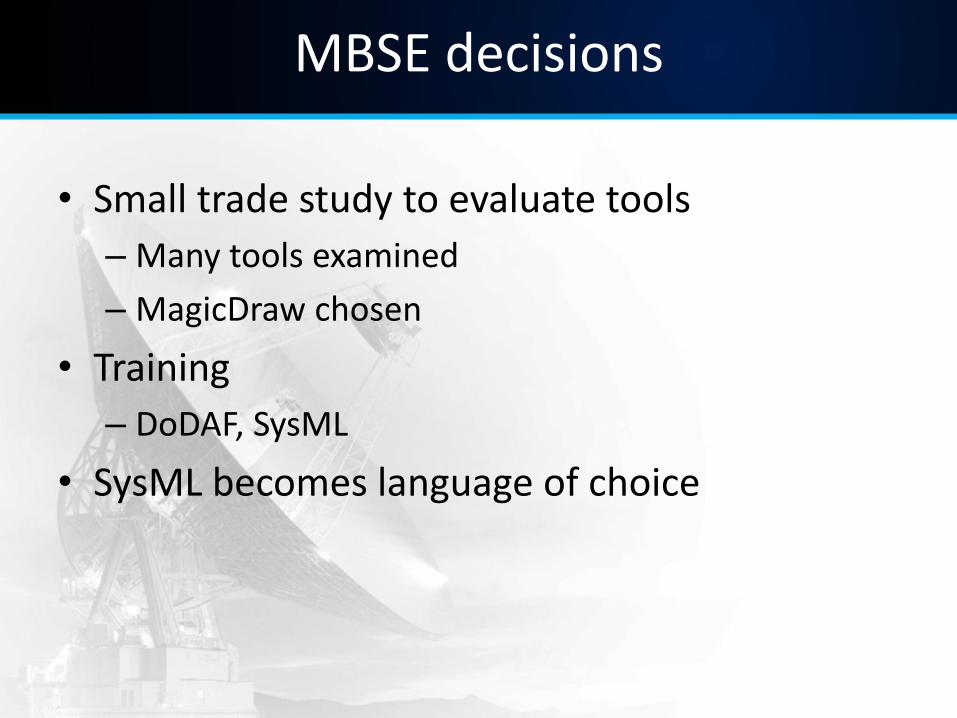
MBSE decisions
• Small trade study to evaluate tools
– Many tools examined
– MagicDraw chosen
• Training
– DoDAF, SysML
• SysML becomes language of choice
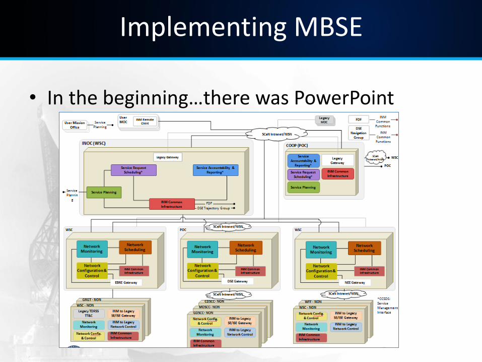
Implementing MBSE
• In the beginning…there was PowerPoint
Implementing MBSE
• PowerPoint used to create architecture models
• DOORS/Excel used to track requirements, asset data, cost analysis, workforce numbers
• Congruency across models/information becomes troublesome
Transitioning to MBSE
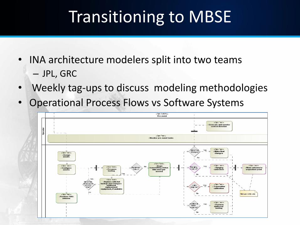
• INA architecture modelers split into two teams – JPL, GRC
• Weekly tag-ups to discuss modeling methodologies
• Operational Process Flows vs Software Systems
Transitioning to MBSE
• Benefits of MBSE realized immediately
– Reuse of model elements
– Accelerated new team member training
– “One-stop shopping”
• Diagrams grow increasingly complex and detailed
• Current INA architecture MBSE model contains ~100 diagrams
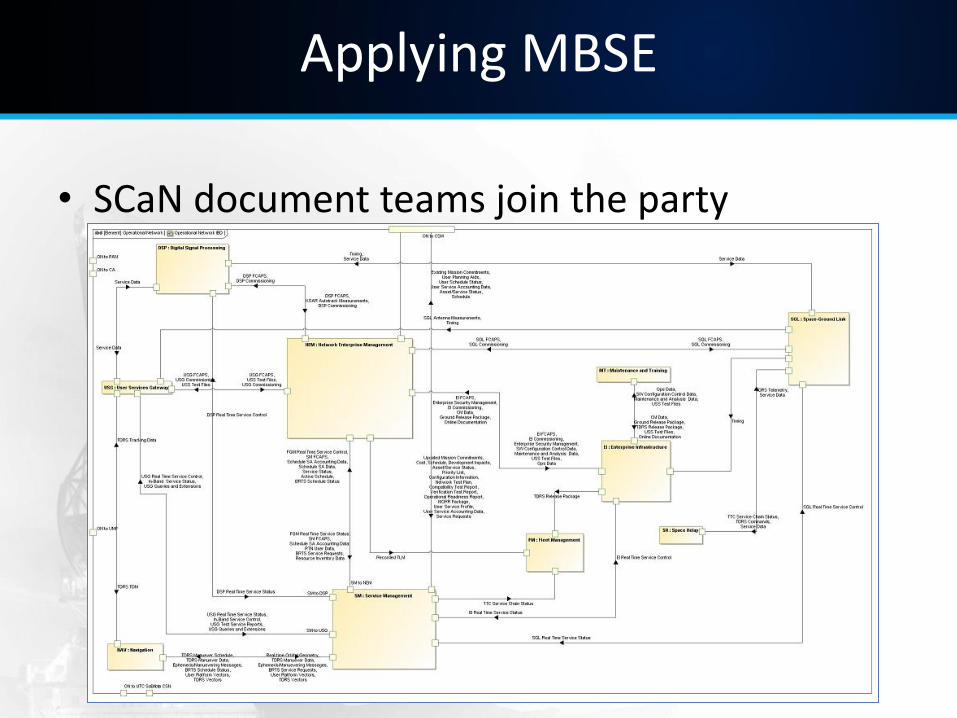
Applying MBSE
• SCaN document teams join the party
Applying MBSE
• MBSE spreads across SCaN book teams
– Previously used Visio, PowerPoint, Illustrator
– SCaN Chief Architect supports transition
– INA modelers and MBSE “infect” the teams
– Initial resistance, then full adaptation
– Integration across document teams still in progress
Applying MBSE
• ConOps scenario diagram example
Current status of MBSE usage
• MBSE being implemented at all centers supporting SCaN
• MBSE deliverables for all new projects
• Novice modelers trained by veterans
• Models form the base of SE work
• Methodology based on previous MBSE work done by INA architecture team
Current status of MBSE usage in Portal
• Service Planning portal development project
– L2 requirements added to model
– Requirements mapped to software systems to show traceability
– Several layers of software/hardware diagrams
– Operational Process Flow to display operational process/user interaction
– Team begins development work based on model designs
Current status of MBSE usage
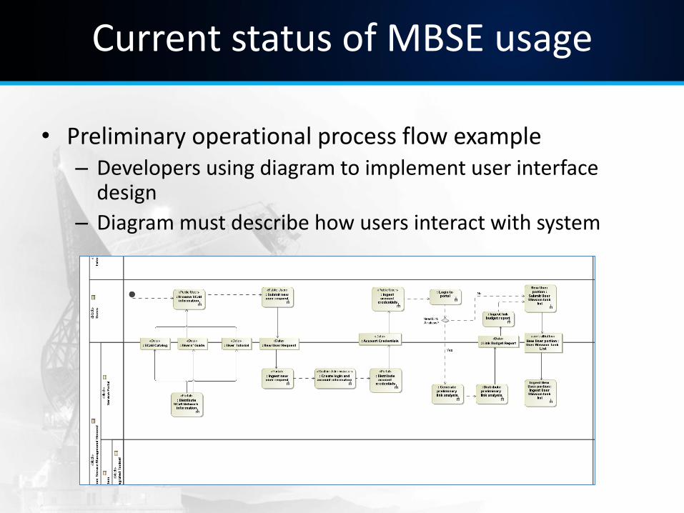
• Preliminary operational process flow example – Developers using diagram to implement user interface
design
– Diagram must describe how users interact with system
Current status of MBSE usage for requirements
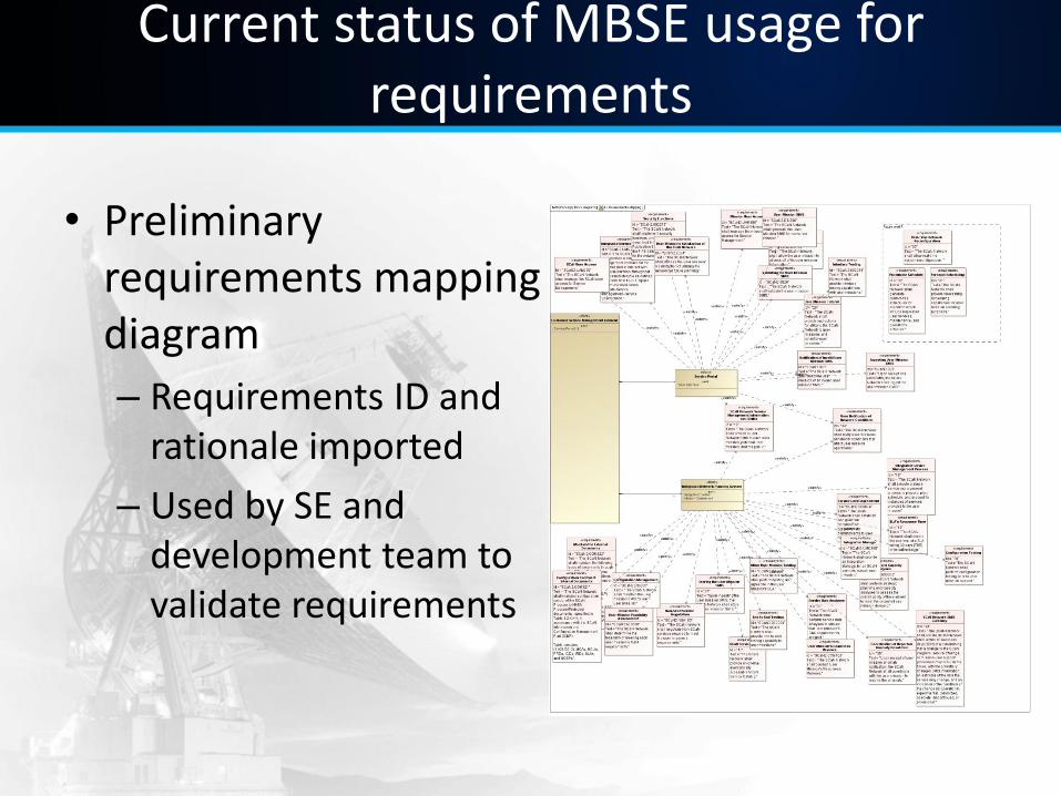
• Preliminary requirements mapping diagram
– Requirements ID and rationale imported
– Used by SE and development team to validate requirements
Conclusion
• MBSE methodology continues to evolve
– Refinement continues in all teams
• MBSE adoption increases
– New SCaN projects using MBSE as primary architecture tool
• Barriers remain with MBSE usage
– Learning curve for MBSE
– Reluctance to abandon Document based SE

Thank you
Questions?

Backup
Acknowledgments
• SCaN Program Systems Engineering team
– Glenn Research Center
– Jet Propulsion Laboratory
– Goddard Space Flight Center
– NASA Headquarters
• Other team members
– Subject Matter Experts
– SCaN Architecture and Requirements team
References
• [1] B. Younes, TDRS-K Press Briefing, p. 5, Jan. 2013, unpublished.
• [2] “Model-Based Systems Engineering with SysML”, Seminar Notes, Cris Kobryn