Embed Size (px)
Citation preview

User’sManual
IM AQ7280-02EN1st Edition
AQ7280 OTDRGetting Started Guide
IM AQ7280-02EN 1
1st Edition: October 2014 (YMI)All Rights Reserved, Copyright © 2014, Yokogawa Meters & Instruments Corporation
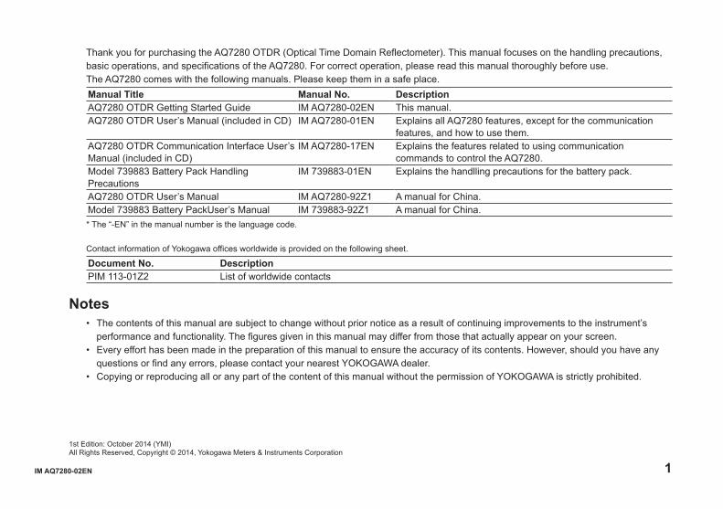
Thank you for purchasing the AQ7280 OTDR (Optical Time Domain Reflectometer). This manual focuses on the handling precautions, basic operations, and specifications of the AQ7280. For correct operation, please read this manual thoroughly before use.The AQ7280 comes with the following manuals. Please keep them in a safe place.Manual Title Manual No. DescriptionAQ7280 OTDR Getting Started Guide IM AQ7280-02EN This manual.AQ7280 OTDR User’s Manual (included in CD) IM AQ7280-01EN Explains all AQ7280 features, except for the communication
features, and how to use them.AQ7280 OTDR Communication Interface User’s Manual (included in CD)
IM AQ7280-17EN Explains the features related to using communication commands to control the AQ7280.
Model 739883 Battery Pack Handling Precautions
IM 739883-01EN Explains the handlling precautions for the battery pack.
AQ7280 OTDR User’s Manual IM AQ7280-92Z1 A manual for China.Model 739883 Battery PackUser’s Manual IM 739883-92Z1 A manual for China.* The “-EN” in the manual number is the language code.
Contact information of Yokogawa offices worldwide is provided on the following sheet.
Document No. DescriptionPIM 113-01Z2 List of worldwide contacts
Notes• The contents of this manual are subject to change without prior notice as a result of continuing improvements to the instrument’s
performance and functionality. The figures given in this manual may differ from those that actually appear on your screen.• Every effort has been made in the preparation of this manual to ensure the accuracy of its contents. However, should you have any
questions or find any errors, please contact your nearest YOKOGAWA dealer.• Copying or reproducing all or any part of the content of this manual without the permission of YOKOGAWA is strictly prohibited.

2 IM AQ7280-02EN
Trademarks• Microsoft and Windows are either registered trademarks or trademarks of Microsoft Corporation in the United States and/or other
countries.• Adobe and Acrobat are trademarks of Adobe Systems Incorporated.• In this manual, the TM and ® symbols do not accompany their respective registered trademark or trademark names.• Other company and product names are registered trademarks or trademarks of their respective holders.
RevisionsOctober 2014 1st Edition

IM AQ7280-02EN 3
Product RegistrationThank you for purchasing YOKOGAWA products.
YOKOGAWA provides registered users with a variety of information and services.Please allow us to serve you best by completing the product registration form accessible from our homepage.
http://tmi.yokogawa.com/
4 IM AQ7280-02EN
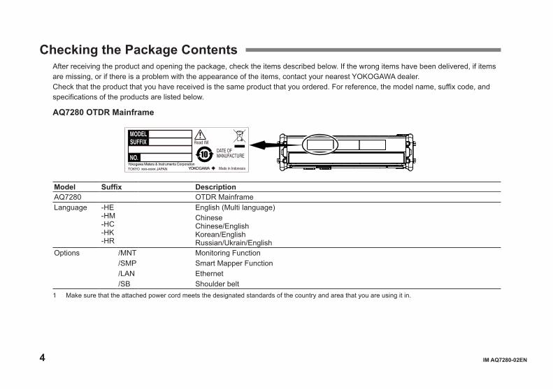
Checking the Package ContentsAfter receiving the product and opening the package, check the items described below. If the wrong items have been delivered, if items are missing, or if there is a problem with the appearance of the items, contact your nearest YOKOGAWA dealer.Check that the product that you have received is the same product that you ordered. For reference, the model name, suffix code, and specifications of the products are listed below.
AQ7280 OTDR Mainframe
xxx-xxxx
Model Suffix DescriptionAQ7280 OTDR MainframeLanguage -HE
-HM-HC-HK-HR
English (Multi language)ChineseChinese/EnglishKorean/EnglishRussian/Ukrain/English
Options /MNT Monitoring Function/SMP Smart Mapper Function/LAN Ethernet/SB Shoulder belt
1 Make sure that the attached power cord meets the designated standards of the country and area that you are using it in.
IM AQ7280-02EN 5
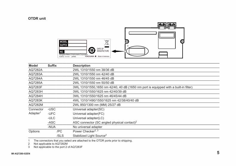
OTDR unit
xxx-xxxx
Model Suffix DescriptionAQ7282A 2WL 1310/1550 nm 38/36 dBAQ7283A 2WL 1310/1550 nm 42/40 dBAQ7284A 2WL 1310/1550 nm 46/45 dBAQ7285A 2WL 1310/1550 nm 50/50 dBAQ7283F 3WL 1310/1550,1650 nm 42/40, 40 dB (1650 nm port is equipped with a built-in filter)AQ7283H 3WL 1310/1550/1625 nm 42/40/39 dBAQ7284H 3WL 1310/1550/1625 nm 46/45/44 dBAQ7283K 4WL 1310/1490/1550/1625 nm 42/38/40/40 dBAQ7282M 2WL 850/1300 nm (MM) 25/27 dBConnector Adapter1
-USC Universal adapter(SC)-UFC Universal adapter(FC)-ULC Universal adapter(LC)-ASC ASC connector (SC angled physical contact)2
-NUA No universal adapterOptions /PC Power Checker2, 3
/SLS Stabilized Light Source2
1 The connectors that you select are attached to the OTDR ports prior to shipping.2 Not applicable to AQ7282M3 Not applicable to the port 2 of AQ7283F

6 IM AQ7280-02EN
Optical power meter module(OPM module)
Model Suffix DescriptionAQ2780 OPM module Power range: –70 dBm to +10 dBm (CW)AQ2781 High Power OPM module Power range: –50 dBm to +27 dBm (CW)AQ2780V OPM & VLS module Power range: –70 dBm to +10 dBm (CW)
with Visible Light Source (Connector: ɸ2.5 Ferrule)AQ2781V High Power OPM & VLS
modulePower range: –50 dBm to +27 dBm (CW)with Visible Light Source (Connector: ɸ2.5 Ferrule)
Connector Adapter1
-SCC Universal adapter(SC)-FCC Universal adapter(FC)-LMC Ferrule adapter (ɸ1.25)
1 The connectors that you select are attached to the OPM ports prior to shipping.

IM AQ7280-02EN 7
AQ4780 Visible light source module
xxx-xxxx
Model Suffix Code DescriptionAQ4780 VLS module Visible Light Source (Connector: ɸ2.5 Ferrule)
No. (Instrument number)When contacting the dealer from which you purchased the instrument, please tell them the instrument number.
8 IM AQ7280-02EN
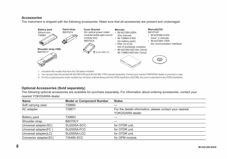
AccessoriesThe instrument is shipped with the following accessories. Make sure that all accessories are present and undamaged.
Hand strapB8070CX
Cover Bracket(for optical power meter module/visible light source module slot)B8070CX
Screw (M4 x 5)
Battery pack(lithium-ion)739883
Shoulder strap (/SB)B8070CY1
Manuals• IM AQ7280-02EN (this manual)• IM 739883-01EN (for battery pack)• PIM 113-01Z2 (list of worldwide contacts)• IM AQ7280-92Z1(for China) IM 739883-92Z1(for China)
Manuals(CD)B8107VA2
• IM AQ7280-01EN (User’ s manual)• IM AQ7280-17EN (for communication interface)
1 Included with models that have the /SB option installed.2 You can purchase the printed IM AQ7280-01EN and IM AQ7280-17EN manuals separately. Contact your nearest YOKOGAWA dealer to purchase a copy.3 If a VLS or optical power meter module has not been ordered along with the OTDR mainframe (AQ7280), the cover is attached to the OTDR mainframe.
Optional Accessories (Sold separately)The following optional accessories are available for purchase separately. For information about ordering accessories, contact your nearest YOKOGAWA dealer.Name Model or Component Number NotesSoft carrying case 739860 —AC adapter 739871 For the details information, please contact your nearest
YOKOGAWA dealer.Battery pack 739883 —Shoulder strap B8070CY —Universal adapter(SC) SU2005A-SCC for OTDR unit.Universal adapter(FC ) SU2005A-FCC for OTDR unit.Universal adapter(LC) SU2005A-LCC for OTDR unit.Connector adapter(SC) 735480-SCC for OPM module.
IM AQ7280-02EN 9
Name Model or Component Number NotesConnector adapter(FC) 735480-FCC for OPM module.Ferrule adapter (1.25f) 735481-LMC for OPM moduleFerrule adapter (2.5f) 735481-SFC for OPM module
Manual CD
WARNINGNever play this CD-ROM on an audio CD player. Doing so may cause loss of hearing or speaker damage due to the large sounds that may be generated.
The English folder of manual CD contains PDF files of the following manuals. The PDFs of the Japanese manuals are included in the manual CD.File Name Manual Title Manual No.Features and Operation Manual.pdf AQ7280 OTDR User's Manual IM AQ7280-01ENCommunication Interface. pdf AQ7280 OTDR Communication Interface
User's ManualIM AQ7280-17EN
To view above manuals you need Adobe Reader 5.0 or later.

10 IM AQ7280-02EN
Safety PrecautionsThe general safety precautions described herein must be observed during all phases of operation. If the instrument is used in a manner not specified in this guide, the protection provided by the instrument may be impaired. YOKOGAWA assumes no liability for the customer’s failure to comply with these requirements.
The following symbols are used on this instrument. Warning: handle with care. Refer to the user’s manual or service manual. This symbol appears on dangerous locations on the
instrument which require special instructions for proper handling or use. The same symbol appears in the corresponding place in the manual to identify those instructions.
Hazard, radiation of laser apparatus.
Direct current
Stand-by
Failure to comply with the precautions below could lead to injury or death.
WARNINGUse the Instrument Only for Its Intended PurposeThis optical measuring instrument is designed to measure the optical characteristics of light sources and evaluate their performance. Do not use this instrument for anything other than as an optical measuring instrument.Check the Physical AppearanceDo not use the instrument if there is a problem with its physical appearance.AC AdapterDo not use the other than AC adapter designed exclusively for the AQ7280.
IM AQ7280-02EN 11
Battery PackOnly use the AQ7280 battery pack. Do not use this battery pack with other instruments. Only use the AQ7280 to charge the battery pack. If the battery pack is still charging after 6 hours, stop charging it immediately. Your clothing may be damaged or you may be injured if you come in contact with the electrolyte due to fluid leakage or the battery pack exploding. Because the electrolyte may cause loss of eyesight, if it comes in contact with your eyes, immediately wash the affected area with clean water, and consult a doctor as soon as possible. When you change the battery pack, be sure to turn the AQ7280 off, and detach the AC adapter power supply from the AQ7280. Failure to do so may lead to electric shock or other accidents. Do not throw the battery pack into fire or heat it. Such actions are dangerous as they may cause the battery pack to explode or the electrolyte to be sprayed about. Follow the additional handling precautions that are included in the battery pack’s user’s manual.Laser BeamDo not look directly or indirectly into the laser beam or at a specular reflection of the beam without protective equipment. Do not aim the laser beam at the eye. The laser beam may cause blindness or damage to your eyes. Attach the cover to the optical connector when it is not in use. Turn the power OFF when you are cleaning the AQ7280.Connecting Optical Fiber CablesUse optical fiber cable connectors that conform to the included universal adapter (the universal adapter specified by the suffix code).Apply Correct Signals to the Optical ConnectorsDo not apply light that is –5 dBm or greater to the OTDR unit (AQ7282 series) optical connectors (PORT1 and PORT2).Doing so may damage the OTDR unit.Do not apply light that is +10 dBm or greater to the OPM module (AQ2780, AQ2780V). Do not apply light that is +27 dBm or greater to the high power OPM module (AQ2781, AQ2781V). Doing so may damage the OPM module.Do Not Operate in an Explosive AtmosphereDo not use the instruments in the presence of flammable gasses or vapors. Doing so is extremely dangerous.Do Not Remove the Covers or Disassemble or Alter the InstrumentOnly qualified YOKOGAWA personnel may remove the covers and disassemble or alter the instrument.Installation PositionHandling the stand without firmly supporting the instrument can be dangerous. Only handle the stand when the instrument is on a stable surface.
12 IM AQ7280-02EN
See below for operating environment limitations.
CAUTIONThis product is a Class A (for industrial environments) product. Operation of this product in a residential area may cause radio interference in which case the user will be required to correct the interference.
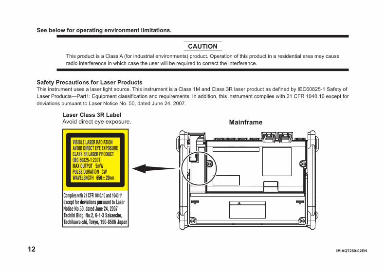
Safety Precautions for Laser ProductsThis instrument uses a laser light source. This instrument is a Class 1M and Class 3R laser product as defined by IEC60825-1 Safety of Laser Products—Part1: Equipment classification and requirements. In addition, this instrument complies with 21 CFR 1040.10 except for deviations pursuant to Laser Notice No. 50, dated June 24, 2007.
Laser Class 3R LabelAvoid direct eye exposure. Mainframe
IM AQ7280-02EN 13
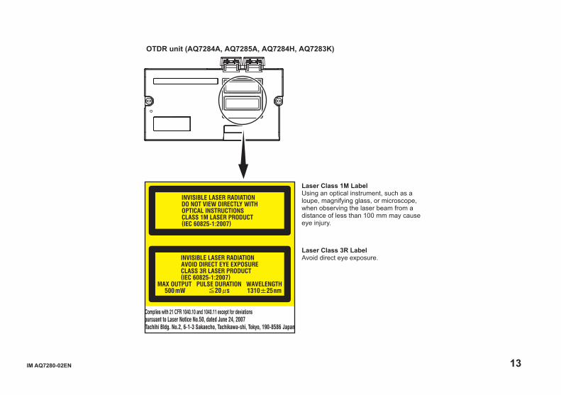
Laser Class 3R LabelAvoid direct eye exposure.
OTDR unit (AQ7284A, AQ7285A, AQ7284H, AQ7283K)
Laser Class 1M LabelUsing an optical instrument, such as a loupe, magnifying glass, or microscope, when observing the laser beam from a distance of less than 100 mm may cause eye injury.
14 IM AQ7280-02EN
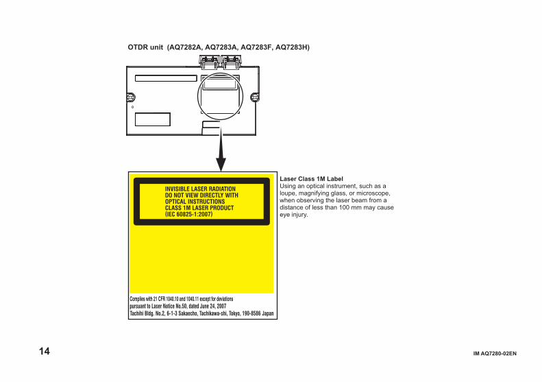
OTDR unit (AQ7282A, AQ7283A, AQ7283F, AQ7283H)
Laser Class 1M LabelUsing an optical instrument, such as a loupe, magnifying glass, or microscope, when observing the laser beam from a distance of less than 100 mm may cause eye injury.

IM AQ7280-02EN 15
Laser Class 3R LabelAvoid direct eye exposure.
OTDR unit (AQ7282M)
Laser Class 1M LabelUsing an optical instrument, such as a loupe, magnifying glass, or microscope, when observing the laser beam from a distance of less than 100 mm may cause eye injury.
16 IM AQ7280-02EN
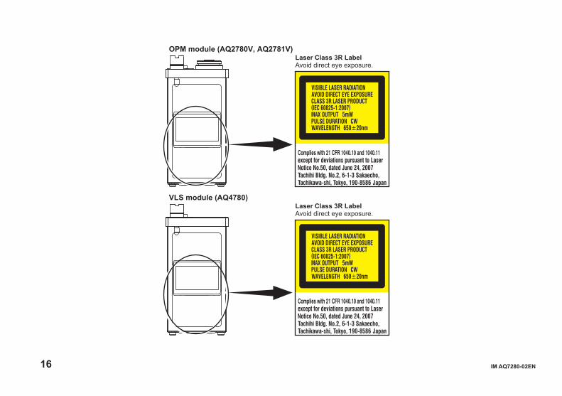
OPM module (AQ2780V, AQ2781V)Laser Class 3R LabelAvoid direct eye exposure.
VLS module (AQ4780)Laser Class 3R LabelAvoid direct eye exposure.

IM AQ7280-02EN 17
OTDR unitModel Class Center Wavelength Maximum Output Power1 Mode Field
DiameterBeam Divergence
AQ7282A 1M 1310 nm/1550 nm CW: 50 mW@1310 nm/1550 nmPULSE: 200 mW@1310 nm/1550 nmPULSE width: 20 μs@1310 nm/1550 nm, Duty: ≤ 3.0%
9 μm 11.5°
AQ7283A 1M 1310 nm/1550 nm CW: 50 mW@1310 nm/1550 nmPULSE: 200 mW@1310 nm/1550 nmPULSE width: 20 μs@1310 nm/1550 nm, Duty: ≤ 3.0%
9 μm 11.5°
AQ7284A 3R 1310 nm CW: 140 mW@1310 nm/1550 nmPULSE: 500 mW@1310 nm/1550 nmPULSE width: 20 μs@1310 nm/1550 nm, Duty: ≤ 3.0%
9 μm 11.5°
1M 1550 nm
AQ7285A 3R 1310 nm CW: 140 mW@1310 nm/1550 nmPULSE: 500 mW@1310 nm/1550 nmPULSE width: 20 μs@1310 nm/1550 nm, Duty: ≤ 3.0%
9 μm 11.5°
1M 1550 nm
AQ7283F 1M 1310 nm/1550 nm,1650 nm
CW: 50 mW@1310 nm/1550 nm/1650 nmPULSE: 200 mW@1310 nm/1550 nm/1650 nmPULSE width: 20 μs@1310 nm/1550 nm/1650 nm, Duty: ≤ 3.0%
9 μm 11.5°
AQ7283H 1M 1310 nm/1550 nm/ 1625 nm
CW: 50 mW@1310 nm/1550 nm/1625 nmPULSE: 200 mW@1310 nm/1550 nm/1625 nmPULSE width: 20 μs@1310 nm/1550 nm/1625 nm, Duty: ≤ 3.0%
9 μm 11.5°
AQ7284H 3R 1310 nm CW: 140 mW@1310 nm/1550 nm/1625 nmPULSE: 500 mW@1310 nm/1550 nm/1625 nmPULSE width: 20 μs@1310 nm/1550 nm/1625 nm, Duty: ≤ 3.0%
9 μm 11.5°
1M 1550 nm/1625 nm
AQ7283K 3R 1310 nm CW: 140 mW@1310 nm/1490 nm/1550 nm/1625 nmPULSE: 500 mW@1310 nm/1490 nm/1550 nm/1625 nmPULSE width: 20 μs@1310 nm/1490 nm/1550 nm/1625 nm, Duty: ≤ 3.0%
9 μm 11.5°
1M 1490 nm/1550 nm/1625 nm
AQ7282M 3R 850 nm CW: 400 mW@850 nm/1300 nmPULSE width: 1 μs@850 nm, Duty: ≤ 2.5%PULSE width: 5 μs@1300 nm, Duty: ≤ 1.2%
50 μm 23.1°
1M 1300 nm
1 Under single fault conditions.
18 IM AQ7280-02EN
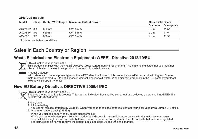
OPM/VLS moduleModel Class Center Wavelength Maximum Output Power1 Mode Field
DiameterBeam Divergence
AQ2780V 3R 650 nm CW: 5 mW 9 μm 11.5°AQ2781V 3R 650 nm CW: 5 mW 9 μm 11.5°AQ4780 3R 650 nm CW: 5 mW 9 μm 11.5°1 Under single fault conditions.
Sales in Each Country or RegionWaste Electrical and Electronic Equipment (WEEE), Directive 2012/19/EU
(This directive is valid only in the EU.) This product complies with the WEEE Directive (2012/19/EU) marking requirement. This marking indicates that you must not
discard this electrical/electronic product in domestic household waste. Product Category
With reference to the equipment types in the WEEE directive Annex 1, this product is classified as a “Monitoring and Control instrumentation” product. Do not dispose in domestic household waste. When disposing products in the EU, contact your local Yokogawa Europe B. V. office.
New EU Battery Directive, DIRECTIVE 2006/66/EC (This directive is valid only in the EU.)
Batteries are included in this product. This marking indicates they shall be sorted out and collected as ordained in ANNEX II in DIRECTIVE 2006/66/EC.
Battery type: 1. Lithium battery You cannot replace batteries by yourself. When you need to replace batteries, contact your local Yokogawa Europe B.V.office. 2. lithium-ion battery pack (739883) When you dispose battery pack, do not disassemble it. When you remove battery pack from this product and dispose it, discard it in accordance with domestic law concerning
disposal.Take a right action on waste batteries, because the collection system in the EU on waste batteries are regulated. For instructions on how to remove the battery pack, see page 29 and 30 in this manual.
IM AQ7280-02EN 19
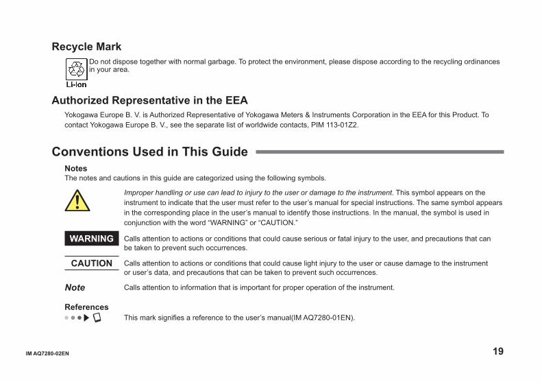
Recycle Mark Do not dispose together with normal garbage. To protect the environment, please dispose according to the recycling ordinances in your area.
Authorized Representative in the EEAYokogawa Europe B. V. is Authorized Representative of Yokogawa Meters & Instruments Corporation in the EEA for this Product. To contact Yokogawa Europe B. V., see the separate list of worldwide contacts, PIM 113-01Z2.
Conventions Used in This GuideNotesThe notes and cautions in this guide are categorized using the following symbols.
Improper handling or use can lead to injury to the user or damage to the instrument. This symbol appears on the instrument to indicate that the user must refer to the user’s manual for special instructions. The same symbol appears in the corresponding place in the user’s manual to identify those instructions. In the manual, the symbol is used in conjunction with the word “WARNING” or “CAUTION.”
WARNING Calls attention to actions or conditions that could cause serious or fatal injury to the user, and precautions that can be taken to prevent such occurrences.
CAUTION Calls attention to actions or conditions that could cause light injury to the user or cause damage to the instrument or user’s data, and precautions that can be taken to prevent such occurrences.
Note Calls attention to information that is important for proper operation of the instrument.
References This mark signifies a reference to the user’s manual(IM AQ7280-01EN).
20 IM AQ7280-02EN
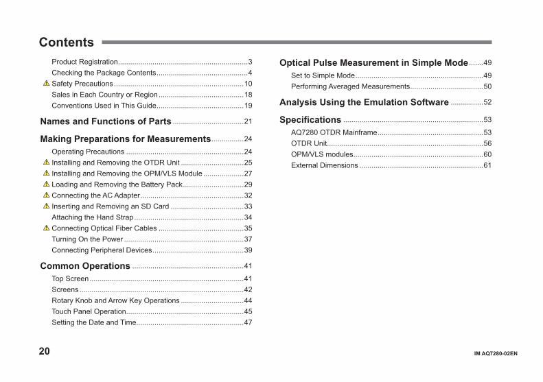
ContentsProduct Registration ................................................................3Checking the Package Contents .............................................4 Safety Precautions ................................................................10Sales in Each Country or Region ..........................................18Conventions Used in This Guide ...........................................19
Names and Functions of Parts ...................................21
Making Preparations for Measurements ................24
Operating Precautions ..........................................................24 Installing and Removing the OTDR Unit ...............................25 Installing and Removing the OPM/VLS Module ....................27 Loading and Removing the Battery Pack ..............................29 Connecting the AC Adapter ...................................................32 Inserting and Removing an SD Card ....................................33Attaching the Hand Strap ......................................................34 Connecting Optical Fiber Cables ..........................................35Turning On the Power ...........................................................37Connecting Peripheral Devices .............................................39
Common Operations .......................................................41
Top Screen ............................................................................41Screens .................................................................................42Rotary Knob and Arrow Key Operations ...............................44Touch Panel Operation ..........................................................45Setting the Date and Time .....................................................47
Optical Pulse Measurement in Simple Mode .......49
Set to Simple Mode ...............................................................49Performing Averaged Measurements ....................................50
Analysis Using the Emulation Software ................52
Specifications .....................................................................53
AQ7280 OTDR Mainframe ....................................................53OTDR Unit .............................................................................56OPM/VLS modules ................................................................60External Dimensions .............................................................61
IM AQ7280-02EN 21
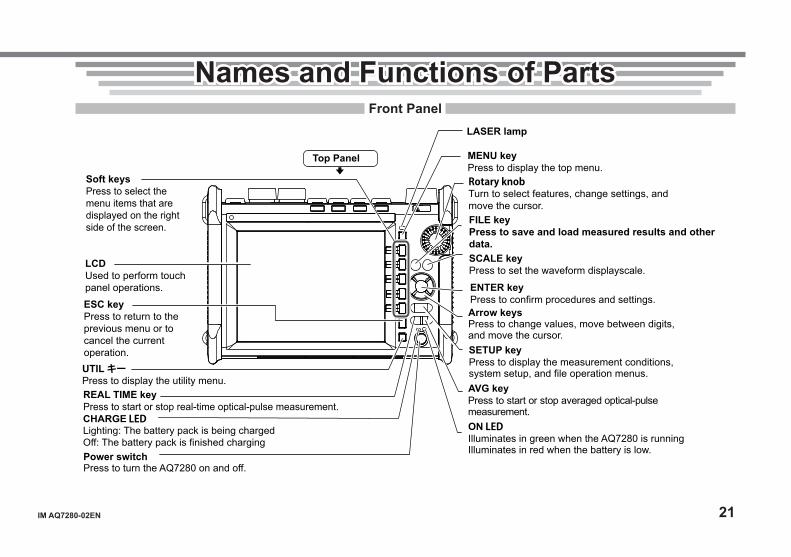
Names and Functions of PartsFront Panel
Power switchPress to turn the AQ7280 on and off.
CHARGE LEDLighting: The battery pack is being chargedOff: The battery pack is finished charging
ESC keyPress to return to the previous menu or to cancel the current operation.
Soft keysPress to select the menu items that are displayed on the right side of the screen.
LCDUsed to perform touch panel operations.
AVG keyPress to start or stop averaged optical-pulse measurement.
MENU keyPress to display the top menu.
REAL TIME keyPress to start or stop real-time optical-pulse measurement.
Rotary knobTurn to select features, change settings, and move the cursor.
ENTER keyPress to confirm procedures and settings.
SETUP keyPress to display the measurement conditions, system setup, and file operation menus.
ON LEDIlluminates in green when the AQ7280 is runningIlluminates in red when the battery is low.
SCALE keyPress to set the waveform displayscale.
FILE keyPress to save and load measured results and other data.
LASER lamp
UTIL キーPress to display the utility menu.
Top Panel
Arrow keysPress to change values, move between digits, and move the cursor.

22 IM AQ7280-02EN
Side Panel
DC power supply connectorUsed to connect the AC adapter(Sold separately).
OTDR/light source/power checker port(OTDR Unit)OTDR/light source port(OTDR Unit)
USB type-A portUsed to connect a USB memory device or a USB printer.
USB type-B port (Mini-B)Used to control the AQ7280 from a PC through communication commands or to access the AQ7280 internal memory from a PC.
Ethernet port (optional)Used to connect the AQ7280 to a networkFront Panel
OTDR Unit Rear Panel
Optical power meter/visible light source module slot
Names and Functions of Parts

IM AQ7280-02EN 23
Rear and Side Panels
OTDR Unit
Battery cover*
Shoulder belt bracket
Hand belt bracket
Battery cover screws
OTDR unit installation screw
StandPull the stand out to use the AQ7280 in a tilted position.
*: SD memory card slot is located under the battery pack.
Names and Functions of Parts
24 IM AQ7280-02EN
Making Preparations for MeasurementsOperating Precautions
Safety PrecautionsIf you are using this instrument for the first time, make sure to thoroughly read “Safety Precautions,” on pages 7 to 10.Do Not Remove the CaseDo not remove the case from the instrument. Doing so is extremely dangerous. For internal inspection and adjustment, contact your nearest YOKOGAWA dealer.Unplug If Abnormal Behavior OccursIf you notice smoke or unusual odors coming from the instrument, immediately turn off the power, unplug the power cord, and contact your nearest YOKOGAWA dealer.Use the AC Adapter and Power Cord CorrectlyDo not place objects on top of the AC adapter or power cord, and keep them away from heat sources. When removing the plug from the power outlet, do not pull on the cord. Pull from the plug. If the AC adapter or power cord is damaged, contact your nearest YOKOGAWA dealer. Refer to page 3 to 6 for the part number to use when placing an order.
General Handling PrecautionsDo Not Place Objects on Top of the InstrumentNever place objects such as other instruments or objects that contain water on top of the instrument. Doing so may damage the instrument.Do Not Subject the Inputs and Outputs to Mechanical ShockIf the I/O connectors or adapters are subjected to mechanical shock, they may be damaged. The instrument may not perform measurements correctly due to damage or deformation that is not visible to the naked eye.Do Not Scratch the LCDBecause the LCD can be easily scratched, do not allow any sharp objects near it. Also, do not apply vibration or shock to it. Furthermore, do not apply strong shock to the LCD or place objects on top of it.During Extended Periods of Non-UseUnplug the power cord from the outlet. Remove the battery pack from the instrument.When Carrying the InstrumentRemove the power cord and connecting cables. When carrying the instrument, grasp the protector or the attached strap firmly.
IM AQ7280-02EN 25
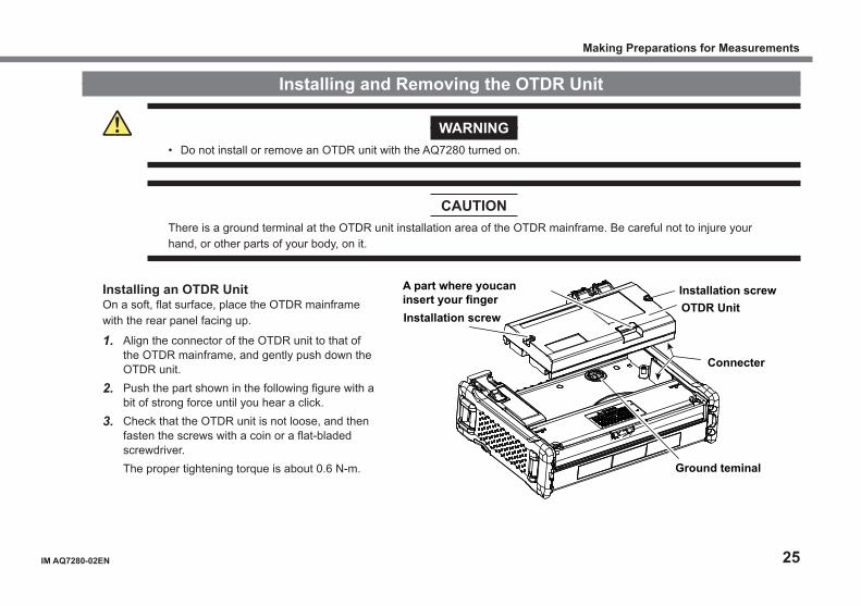
Installing and Removing the OTDR Unit
WARNING• Do not install or remove an OTDR unit with the AQ7280 turned on.
CAUTIONThere is a ground terminal at the OTDR unit installation area of the OTDR mainframe. Be careful not to injure your hand, or other parts of your body, on it.
Making Preparations for Measurements
Installing an OTDR UnitOn a soft, flat surface, place the OTDR mainframe with the rear panel facing up.
1. Align the connector of the OTDR unit to that of the OTDR mainframe, and gently push down the OTDR unit.
2. Push the part shown in the following figure with a bit of strong force until you hear a click.
3. Check that the OTDR unit is not loose, and then fasten the screws with a coin or a flat-bladed screwdriver.
The proper tightening torque is about 0.6 N-m. Ground teminal
Connecter
OTDR UnitInstallation screw
Installation screw
A part where youcan insert your finger
26 IM AQ7280-02EN
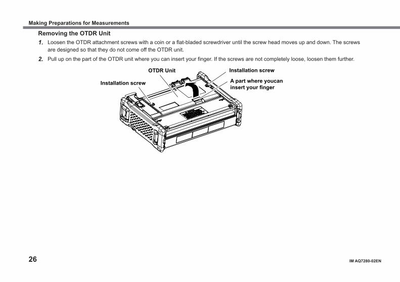
Removing the OTDR Unit1. Loosen the OTDR attachment screws with a coin or a flat-bladed screwdriver until the screw head moves up and down. The screws
are designed so that they do not come off the OTDR unit.
2. Pull up on the part of the OTDR unit where you can insert your finger. If the screws are not completely loose, loosen them further.
OTDR Unit Installation screw
Installation screw A part where youcan insert your finger
Making Preparations for Measurements
IM AQ7280-02EN 27
Installing and Removing the OPM/VLS Module
WARNINGDo not install or remove an optical power meter or visible light source module with the AQ7280 turned on.
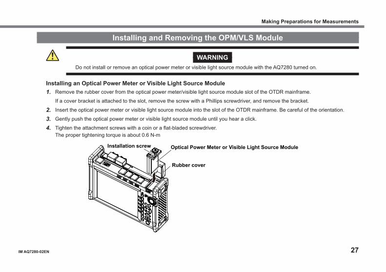
Installing an Optical Power Meter or Visible Light Source Module1. Remove the rubber cover from the optical power meter/visible light source module slot of the OTDR mainframe.
If a cover bracket is attached to the slot, remove the screw with a Phillips screwdriver, and remove the bracket.
2. Insert the optical power meter or visible light source module into the slot of the OTDR mainframe. Be careful of the orientation.
3. Gently push the optical power meter or visible light source module until you hear a click.
4. Tighten the attachment screws with a coin or a flat-bladed screwdriver. The proper tightening torque is about 0.6 N-m
Installation screw Optical Power Meter or Visible Light Source Module
Rubber cover
Making Preparations for Measurements
28 IM AQ7280-02EN
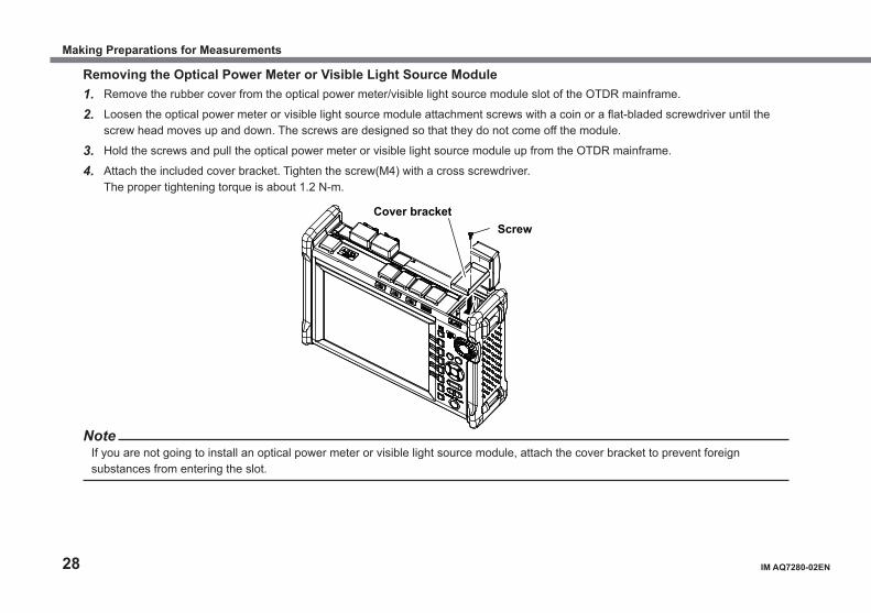
Removing the Optical Power Meter or Visible Light Source Module1. Remove the rubber cover from the optical power meter/visible light source module slot of the OTDR mainframe.
2. Loosen the optical power meter or visible light source module attachment screws with a coin or a flat-bladed screwdriver until the screw head moves up and down. The screws are designed so that they do not come off the module.
3. Hold the screws and pull the optical power meter or visible light source module up from the OTDR mainframe.
4. Attach the included cover bracket. Tighten the screw(M4) with a cross screwdriver. The proper tightening torque is about 1.2 N-m.
Cover bracketScrew
NoteIf you are not going to install an optical power meter or visible light source module, attach the cover bracket to prevent foreign substances from entering the slot.
Making Preparations for Measurements
IM AQ7280-02EN 29
Loading and Removing the Battery Pack
WARNING• Do not connect or disconnect the battery pack while electricity is being supplied by the AC adapter.• To prevent problems before they occur, periodically inspect the battery pack exterior to confirm that there is no damage
such as cracks or deformations and to confirm that there is no fluid leakage.• Only use 739883 battery pack. Do not use this battery pack with other instruments. • Use the AQ7280 to charge the battery pack. Maintain the correct environmental conditions when the battery pack is
charging. Failure to do so can cause fluid leakage, heating, smoke, explosions, or fire. You need a separately sold AC adapter to charge the battery pack.• Follow the handling precautions that are included in the battery pack’s user’s manual.• The battery pack is made of lithium-ion cells. When transporting the AQ7280, remove the battery pack.• For information on transporting lithium-ion batteries by air, see the requirement for each packing instruction (lithium
battery packing instruction Section II) in the latest IATA Dangerous Goods Regulations.
CAUTIONThe battery pack weights approximately 500 g. Be careful not to drop it on your feet or hands.
Making Preparations for Measurements
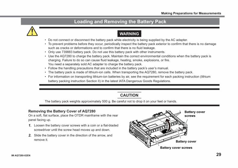
Removing the Battery Cover of AQ7280On a soft, flat surface, place the OTDR mainframe with the rear panel facing up.
1. Loosen the battery cover screws with a coin or a flat-bladed screwdriver until the screw head moves up and down.
2. Slide the battery cover in the direction of the arrow, and remove it.
Battery cover screws
Stand
Battery cover
Battery cover screws
30 IM AQ7280-02EN
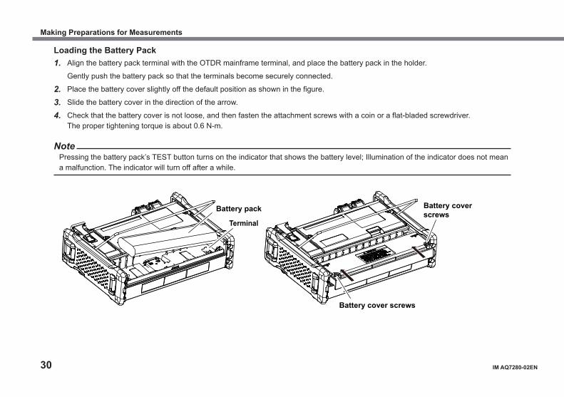
Loading the Battery Pack1. Align the battery pack terminal with the OTDR mainframe terminal, and place the battery pack in the holder.
Gently push the battery pack so that the terminals become securely connected.
2. Place the battery cover slightly off the default position as shown in the figure.
3. Slide the battery cover in the direction of the arrow.
4. Check that the battery cover is not loose, and then fasten the attachment screws with a coin or a flat-bladed screwdriver. The proper tightening torque is about 0.6 N-m.
NotePressing the battery pack’s TEST button turns on the indicator that shows the battery level; Illumination of the indicator does not mean a malfunction. The indicator will turn off after a while.
Terminal
Battery pack
Battery cover screws
Battery cover screws
Making Preparations for Measurements
IM AQ7280-02EN 31
Removing the Battery PackIn the same manner as when loading the battery pack, remove the battery cover.With your fingers, lift the side that does not have the battery terminal.Hold the battery pack securely, and lift it up.
NoteOver Discharge and Long Periods of Storage• If you do not use the AQ7280 for an extended period of time with the battery pack connected to it, the battery pack may become
over discharged. This shortens the service life of the battery pack. To avoid over discharging, if you will not use the AQ7280 for one week or longer, charge the battery pack, remove it from the AQ7280, and store the battery pack away from direct sunlight in a location that has an ambient temperature of 10°C to 30°C.
• When you store the battery pack for six months or longer, to replace the power that has been lost through self discharge, recharge the battery using the AQ7280 once every six months.
• Avoid storing the battery pack for an extended period of time when it is fully charged (after it has just been charged) or when it has no power left (when the AQ7280 will not turn on). Storing the battery pack under these conditions will degrade its performance and reduce its longevity. It is better to store the battery pack when it is 40% to 50% charged. This is equivalent to the state the battery is in after you turn off the AQ7280 and charge an empty battery for an hour at room temperature.
• Use the AQ7280 to charge the battery pack prior to its first use or if it has not been used for an extended period of time.
Making Preparations for Measurements
32 IM AQ7280-02EN
Connecting the AC Adapter
WARNING• Confirm that the AQ7280 is off before you connect the power supply.• Make sure that the power supply voltage matches the AC adapter’s rated supply voltage and that it does not exceed
the maximum voltage range specified for the power cord.• Only use the dedicated AC adapter for the instrument.• Do not connect or disconnect the AC adapter while the AQ7280 is on.• If you are using the AQ7280 for a long time with the AC adapter connected, remove the battery pack from the AQ7280.• If an appropriate AC outlet for the supplied power cord is unavailable, do not use the instrument.
1. Connect the AC adapter’s plug to the AQ7280’s DC power supply connector.
2. Connect the power plug to an outlet.
Note• For details on the AC adapter, contact your nearest YOKOGAWA dealer.• If the DC power supply connector’s cover comes off, bend the cover axle and reattach it.
Making Preparations for Measurements
IM AQ7280-02EN 33
Inserting and Removing an SD Card
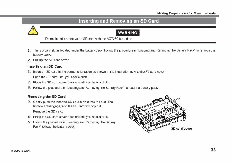
WARNINGDo not insert or remove an SD card with the AQ7280 turned on
1. The SD card slot is located under the battery pack. Follow the procedure in “Loading and Removing the Battery Pack” to remove the battery pack.
2. Pull up the SD card cover.
Inserting an SD Card3. Insert an SD card in the correct orientation as shown in the illustration next to the SD card cover.
Push the SD card until you hear a click.
4. Place the SD card cover back on until you hear a click..
5. Follow the procedure in “Loading and Removing the Battery Pack” to load the battery pack.
Making Preparations for Measurements
Removing the SD Card3. Gently push the inserted SD card further into the slot. The
latch will disengage, and the SD card will pop out.
Remove the SD card.
4. Place the SD card cover back on until you hear a click..
5. Follow the procedure in “Loading and Removing the Battery Pack” to load the battery pack. SD card cover
34 IM AQ7280-02EN
Attaching the Hand Strap
1
2
3
4
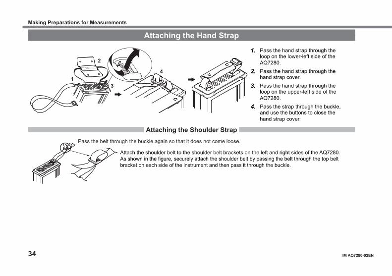
1. Pass the hand strap through the loop on the lower-left side of the AQ7280.
2. Pass the hand strap through the hand strap cover.
3. Pass the hand strap through the loop on the upper-left side of the AQ7280.
4. Pass the strap through the buckle, and use the buttons to close the hand strap cover.
Attaching the Shoulder Strap
Attach the shoulder belt to the shoulder belt brackets on the left and right sides of the AQ7280.As shown in the figure, securely attach the shoulder belt by passing the belt through the top belt bracket on each side of the instrument and then pass it through the buckle.
Pass the belt through the buckle again so that it does not come loose.
Making Preparations for Measurements

IM AQ7280-02EN 35
Connecting Optical Fiber Cables
WARNING• When the AQ7280 generates light, light is emitted from the light source ports. Do not disconnect the connected optical
fiber cables. Visual impairment may occur if the light enters the eye.• Close the covers of any light source ports that do not have optical fiber cables connected to them. On models with two
or more light source ports, visual impairment may occur if light that is mistakenly emitted from the wrong port enters the eye.
CAUTION• Insert the optical fiber cable connectors slowly and straight into the optical ports. If you shake the connector to the left
and right or force it into the port, the optical connector or optical port may be damaged. • If you use optical connectors that do not meet the specifications, the AQ7280 optical ports may be damaged. Use
optical connectors that are approved or used by national or local telecom carriers and providers in your area.• Use optical fiber cable connectors that conform to the included universal adapter and connector adapter (the universal
adapter specified by the suffix code).
Using SC Angled Physical Contact Connectors (Suffix code -ASC of OTDR Unit)• The SC angled physical contact connector’s ferrule tip is angle-polished. Use optical fiber cables whose connectors
are of the same type. Using a different type of connector may damage the connector end face.• Only use SC-type (SU2005A-SCC) universal adapters on -ASC OTDR ports. Otherwise, the AQ7280 optical ports or
the optical fiber cable connectors may be damaged.
Making Preparations for Measurements
36 IM AQ7280-02EN
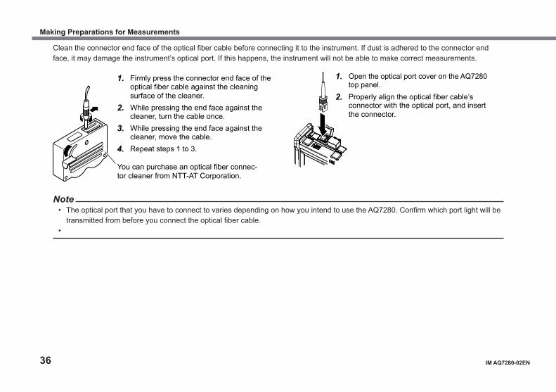
Clean the connector end face of the optical fiber cable before connecting it to the instrument. If dust is adhered to the connector end face, it may damage the instrument’s optical port. If this happens, the instrument will not be able to make correct measurements.
1. Firmly press the connector end face of the optical fiber cable against the cleaning surface of the cleaner.
2. While pressing the end face against the cleaner, turn the cable once.
3. While pressing the end face against the cleaner, move the cable.
4. Repeat steps 1 to 3.
1. Open the optical port cover on the AQ7280 top panel.
2. Properly align the optical fiber cable’s connector with the optical port, and insert the connector.
You can purchase an optical fiber connec-tor cleaner from NTT-AT Corporation.
Note• The optical port that you have to connect to varies depending on how you intend to use the AQ7280. Confirm which port light will be
transmitted from before you connect the optical fiber cable.•
Making Preparations for Measurements
IM AQ7280-02EN 37
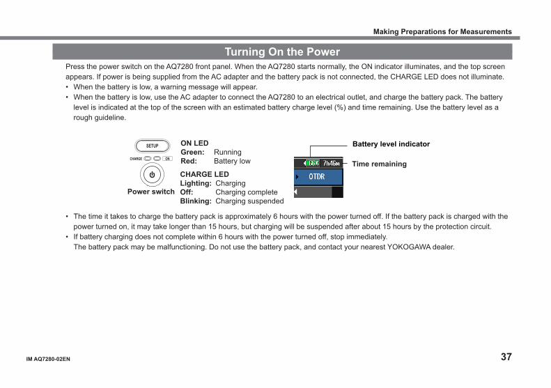
Turning On the PowerPress the power switch on the AQ7280 front panel. When the AQ7280 starts normally, the ON indicator illuminates, and the top screen appears. If power is being supplied from the AC adapter and the battery pack is not connected, the CHARGE LED does not illuminate.• When the battery is low, a warning message will appear.• When the battery is low, use the AC adapter to connect the AQ7280 to an electrical outlet, and charge the battery pack. The battery
level is indicated at the top of the screen with an estimated battery charge level (%) and time remaining. Use the battery level as a rough guideline.
CHARGE LEDLighting: ChargingOff: Charging completeBlinking: Charging suspended
ON LEDGreen: RunningRed: Battery low
Power switch
SETUP
CHARGE ON
Battery level indicator
Time remaining
• The time it takes to charge the battery pack is approximately 6 hours with the power turned off. If the battery pack is charged with the power turned on, it may take longer than 15 hours, but charging will be suspended after about 15 hours by the protection circuit.
• If battery charging does not complete within 6 hours with the power turned off, stop immediately. The battery pack may be malfunctioning. Do not use the battery pack, and contact your nearest YOKOGAWA dealer.
Making Preparations for Measurements

38 IM AQ7280-02EN
When the Power-on Operation Does Not Finish NormallyTurn off the power switch, and check the following items.• Is the AC adapter connected correctly? See page 32.• Is the battery pack loaded correctly? See page 29.• Are you holding down the power switch for at least 2 seconds?If the AQ7280 still does not work properly after checking these items, contact your nearest YOKOGAWA dealer for repairs.
Warm UpTo enable more accurate measurements, allow the AQ7280 to warm up for at least 5 minutes after it is turned on.
Making Preparations for Measurements

IM AQ7280-02EN 39
Connecting Peripheral Devices
PC
Device under measurement
Device under measurement
Device under measurement
USB printerUSB memory
Fiber inspection probe
PC
(VLS module/OPM module)
AC adapter
USB type-A port
Visible light source port/Optical power meter port
Ethernet port *: Remote control
USB type-B port (Mini-B): Storage and remote control
* Option
OTDR/Light source/power checker port(OTDR unit, port 1)
OTDR/Light source port(OTDR unit, port 2)
Making Preparations for Measurements

40 IM AQ7280-02EN
Memo

IM AQ7280-02EN 41
Common OperationsTop Screen
When you turn the AQ7280 on and it starts, the top screen appears. First select a feature from this top screen, and then configure the feature or carry out the measurement that corresponds to the feature you have selected.
1. Turn on the AQ7280.
2. Select a feature.Select it in the following manner.• Select an icon with arrow keys or rotary knob, and press ENTER.• Select a feature with the soft keys.• Tap an icon on the screen.
Rotary knob
ENTER
Soft keySoft key Menu
ENTER key
The center of the rotary knob
Icon of a featur
Icon of an unavailable feature appears dimmed.
42 IM AQ7280-02EN
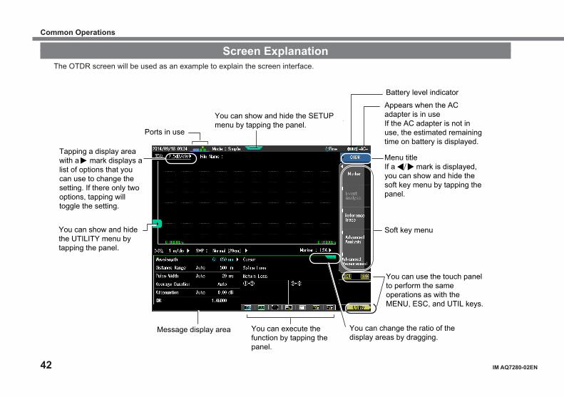
Screen ExplanationThe OTDR screen will be used as an example to explain the screen interface.
You can show and hide the SETUP menu by tapping the panel.
Ports in use
Tapping a display area with a mark displays a list of options that you can use to change the setting. If there only two options, tapping will toggle the setting.
You can show and hide the UTILITY menu by tapping the panel.
Battery level indicator
Appears when the AC adapter is in useIf the AC adapter is not in use, the estimated remaining time on battery is displayed.
Menu titleIf a mark is displayed, you can show and hide the soft key menu by tapping the panel.
You can use the touch panel to perform the same operations as with the MENU, ESC, and UTIL keys.
Message display area You can change the ratio of the display areas by dragging.
You can execute the function by tapping the panel.
Soft key menu
Common Operations

IM AQ7280-02EN 43
Soft Key Menu
There are three types of soft key menus depending on the function.
Pressing a soft key of a menu item with a frame confirms the selected item or executes its corresponding action.
Pressing a soft key of a menu item with a mark displays a setup menu.
Pressing a soft key of a menu item with options switches the selected option.
Common Operations
44 IM AQ7280-02EN
There are three types of soft key menus depending on the function.
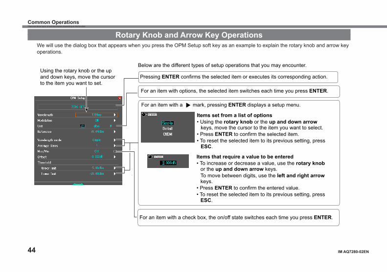
Rotary Knob and Arrow Key OperationsWe will use the dialog box that appears when you press the OPM Setup soft key as an example to explain the rotary knob and arrow key operations.
Using the rotary knob or the up and down keys, move the cursor to the item you want to set.
Below are the different types of setup operations that you may encounter.
For an item with options, the selected item switches each time you press ENTER.
For an item with a mark, pressing ENTER displays a setup menu.
Items set from a list of options• Using the rotary knob or the up and down arrow
keys, move the cursor to the item you want to select.• Press ENTER to confirm the selected item.• To reset the selected item to its previous setting, press
ESC.
Items that require a value to be entered• To increase or decrease a value, use the rotary knob
or the up and down arrow keys.To move between digits, use the left and right arrow keys.
• Press ENTER to confirm the entered value.• To reset the selected item to its previous setting, press
ESC.
For an item with a check box, the on/off state switches each time you press ENTER.
Pressing ENTER confirms the selected item or executes its corresponding action.
Common Operations
IM AQ7280-02EN 45
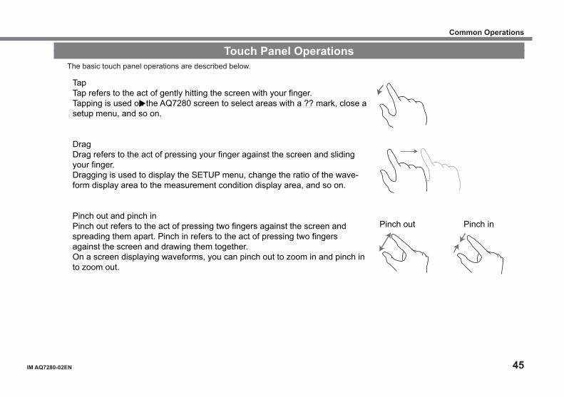
Touch Panel OperationsThe basic touch panel operations are described below.
Pinch out Pinch in
TapTap refers to the act of gently hitting the screen with your finger.Tapping is used on the AQ7280 screen to select areas with a ?? mark, close a setup menu, and so on.
DragDrag refers to the act of pressing your finger against the screen and sliding your finger.Dragging is used to display the SETUP menu, change the ratio of the wave-form display area to the measurement condition display area, and so on.
Pinch out and pinch inPinch out refers to the act of pressing two fingers against the screen and spreading them apart. Pinch in refers to the act of pressing two fingers against the screen and drawing them together.On a screen displaying waveforms, you can pinch out to zoom in and pinch in to zoom out.
Common Operations
46 IM AQ7280-02EN
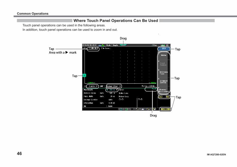
Where Touch Panel Operations Can Be UsedTouch panel operations can be used in the following areas.In addition, touch panel operations can be used to zoom in and out.
TapArea with a mark
Tap
Tap
Tap
Tap
Drag
Drag
Common Operations
IM AQ7280-02EN 47
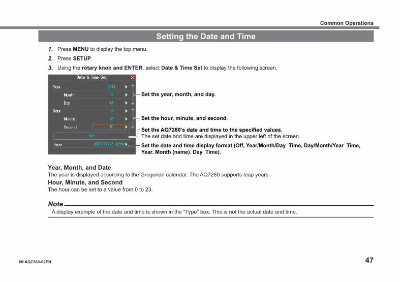
Setting the Date and Time1. Press MENU to display the top menu.
2. Press SETUP.
3. Using the rotary knob and ENTER, select Date & Time Set to display the following screen.
Set the year, month, and day.
Set the hour, minute, and second.
Set the AQ7280’s date and time to the specified values.The set date and time are displayed in the upper left of the screen.
Set the date and time display format (Off, Year/Month/Day Time, Day/Month/Year Time, Year. Month (name). Day Time).
Year, Month, and DateThe year is displayed according to the Gregorian calendar. The AQ7280 supports leap years.Hour, Minute, and SecondThe hour can be set to a value from 0 to 23.
NoteA display example of the date and time is shown in the “Type” box. This is not the actual date and time.
Common Operations

48 IM AQ7280-02EN
Memo

IM AQ7280-02EN 49
Optical Pulse Measurement in Simple ModeConfiguring the Simple Mode Conditions
In this mode, the absolute minimum amount of measurement conditions are set manually. You only have to set the wavelength.Conditions such as Distance Range, Pulse Width, and Event Search are set automatically when measurement starts.
1. Select OTDR.
2. Press SETUP and then the Mode soft key.
3. Press the Simle soft key. The following screen appears.
Set the wavelength (The available wavelengths vary depending on the OTDR unit that is installed.).
50 IM AQ7280-02EN
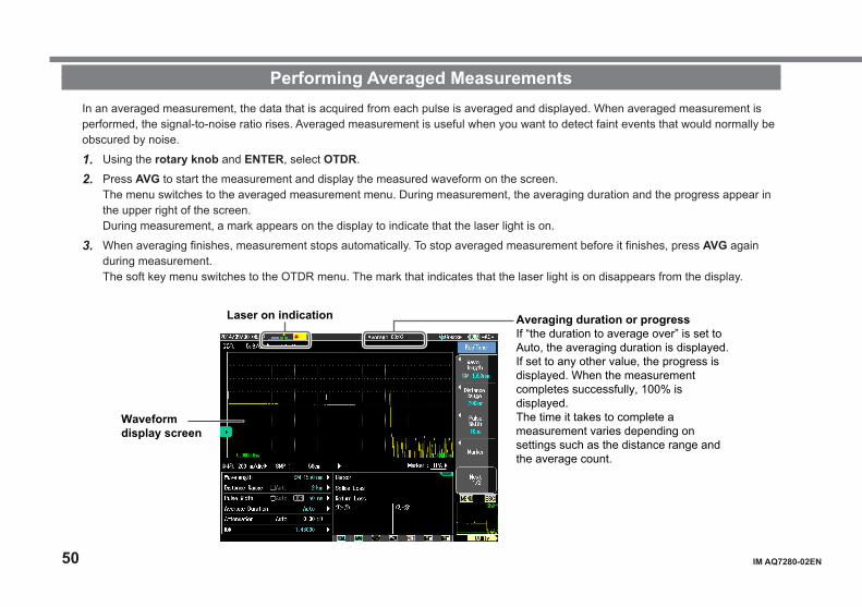
Performing Averaged MeasurementsIn an averaged measurement, the data that is acquired from each pulse is averaged and displayed. When averaged measurement is performed, the signal-to-noise ratio rises. Averaged measurement is useful when you want to detect faint events that would normally be obscured by noise.
1. Using the rotary knob and ENTER, select OTDR.
2. Press AVG to start the measurement and display the measured waveform on the screen.The menu switches to the averaged measurement menu. During measurement, the averaging duration and the progress appear in the upper right of the screen. During measurement, a mark appears on the display to indicate that the laser light is on.
3. When averaging finishes, measurement stops automatically. To stop averaged measurement before it finishes, press AVG again during measurement.The soft key menu switches to the OTDR menu. The mark that indicates that the laser light is on disappears from the display.
Averaging duration or progressIf “the duration to average over” is set to Auto, the averaging duration is displayed.If set to any other value, the progress is displayed. When the measurement completes successfully, 100% is displayed.The time it takes to complete a measurement varies depending on settings such as the distance range and the average count.
Laser on indication
Waveform display screen
IM AQ7280-02EN 51
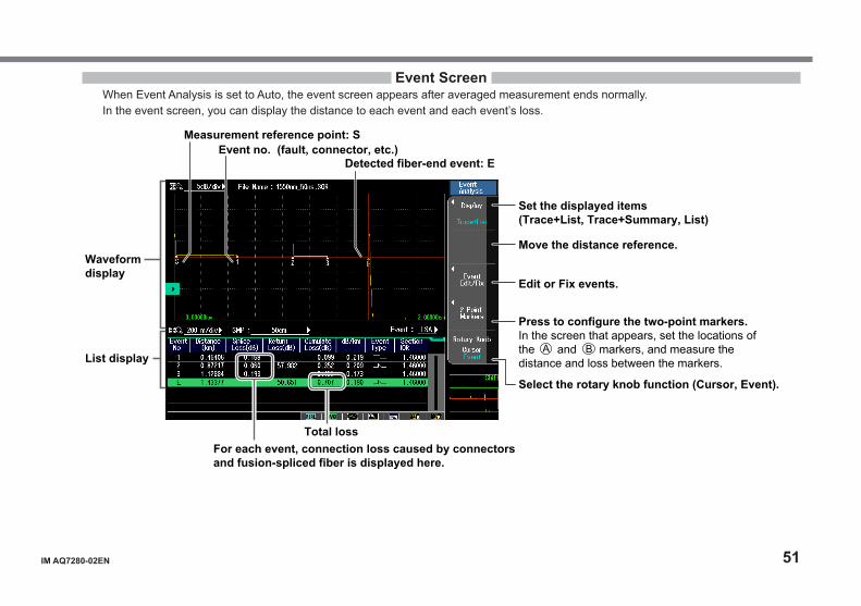
Event ScreenWhen Event Analysis is set to Auto, the event screen appears after averaged measurement ends normally.In the event screen, you can display the distance to each event and each event’s loss.
Measurement reference point: SEvent no. (fault, connector, etc.)
Detected fiber-end event: E
Total loss
A B
For each event, connection loss caused by connectors and fusion-spliced fiber is displayed here.
Waveform display
List display
Set the displayed items (Trace+List, Trace+Summary, List)
Move the distance reference.
Edit or Fix events.
Press to configure the two-point markers. In the screen that appears, set the locations of the and markers, and measure the distance and loss between the markers.
Select the rotary knob function (Cursor, Event).
52 IM AQ7280-02EN
Analysis Using the Emulation SoftwareThe waveform data that is measured by the AQ7280 can be analyzed on your PC using the AQ7932 OTDR emulation software (version 5.01 or later). The software comes with a report creation wizard that is convenient in creating construction reports.
IM AQ7280-02EN 53
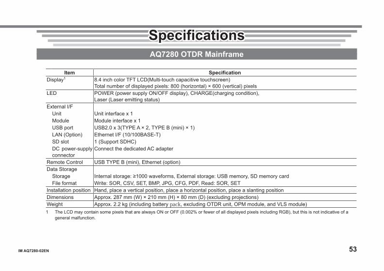
SpecificationsAQ7280 OTDR Mainframe
Item SpecificationDisplay1 8.4 inch color TFT LCD(Multi-touch capacitive touchscreen)
Total number of displayed pixels: 800 (horizontal) × 600 (vertical) pixelsLED POWER (power supply ON/OFF display), CHARGE(charging condition),
Laser (Laser emitting status)External I/F
Unit Unit interface x 1Module Module interface x 1USB port USB2.0 x 3(TYPE A × 2, TYPE B (mini) × 1)LAN (Option) Ethernet I/F (10/100BASE-T)SD slot 1 (Support SDHC)DC power-supply connector
Connect the dedicated AC adapter
Remote Control USB TYPE B (mini), Ethernet (option)Data Storage
Storage Internal storage: ≥1000 waveforms, External storage: USB memory, SD memory cardFile format Write: SOR, CSV, SET, BMP, JPG, CFG, PDF, Read: SOR, SET
Installation position Hand, place a vertical position, place a horizontal position, place a slanting positionDimensions Approx. 287 mm (W) × 210 mm (H) × 80 mm (D) (excluding projections)Weight Approx. 2.2 kg (including battery pack, excluding OTDR unit, OPM module, and VLS module)1 The LCD may contain some pixels that are always ON or OFF (0.002% or fewer of all displayed pixels including RGB), but this is not indicative of a
general malfunction.

54 IM AQ7280-02EN
OTDR FunctionItem Specification
Minimum Readout resolution
Horizontal axis: 1cm, Vertical axis: 0.001dB
Group refractive index
1.30000 to 1.79999 (in 0.00001 steps)
Unit of distance km, mile, kftBack scatter level Selectable: PW=1 µs or 1 nsMeasurement functions
Distance measurement, Loss measurement, Return loss measurement and Return loss measurement between any arbitrary points on the trace.
Analysis functions Multi-wavelength analysis, Two wavelength combine, Difference analysis, Section analysis, Macro bending analysis
Others Multi fiber project, Fault locator, Work completion notice, File report, Auto event search, Pass/Fail judgment, Schedule measurement(Option), Smart mapper (Option)
Specifications
IM AQ7280-02EN 55
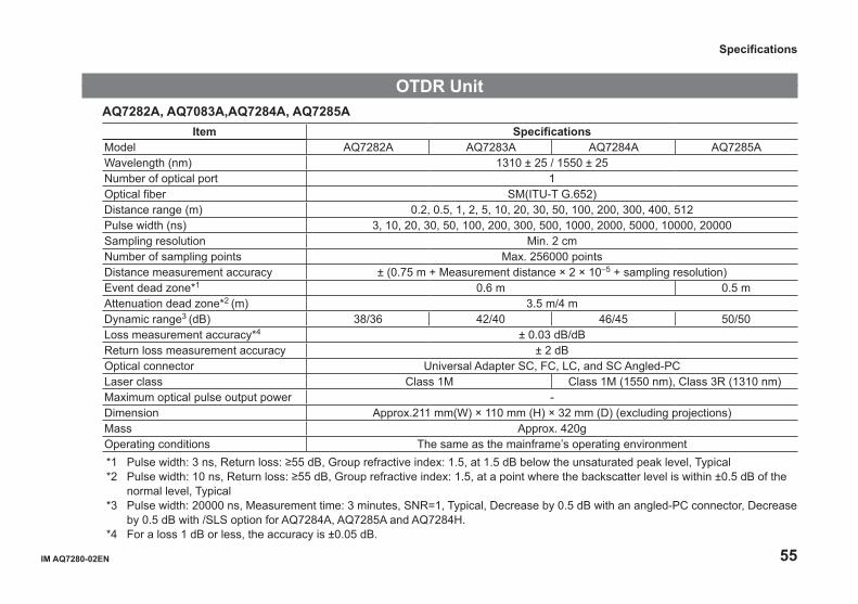
OTDR UnitAQ7282A, AQ7083A,AQ7284A, AQ7285A
Item SpecificationsModel AQ7282A AQ7283A AQ7284A AQ7285AWavelength (nm) 1310 ± 25 / 1550 ± 25Number of optical port 1Optical fiber SM(ITU-T G.652)Distance range (m) 0.2, 0.5, 1, 2, 5, 10, 20, 30, 50, 100, 200, 300, 400, 512Pulse width (ns) 3, 10, 20, 30, 50, 100, 200, 300, 500, 1000, 2000, 5000, 10000, 20000Sampling resolution Min. 2 cmNumber of sampling points Max. 256000 pointsDistance measurement accuracy ± (0.75 m + Measurement distance × 2 × 10⁻⁵ + sampling resolution)Event dead zone*1 0.6 m 0.5 mAttenuation dead zone*2 (m) 3.5 m/4 m Dynamic range3 (dB) 38/36 42/40 46/45 50/50Loss measurement accuracy*4 ± 0.03 dB/dBReturn loss measurement accuracy ± 2 dBOptical connector Universal Adapter SC, FC, LC, and SC Angled-PCLaser class Class 1M Class 1M (1550 nm), Class 3R (1310 nm)Maximum optical pulse output power -Dimension Approx.211 mm(W) × 110 mm (H) × 32 mm (D) (excluding projections)Mass Approx. 420gOperating conditions The same as the mainframe’s operating environment*1 Pulse width: 3 ns, Return loss: ≥55 dB, Group refractive index: 1.5, at 1.5 dB below the unsaturated peak level, Typical*2 Pulse width: 10 ns, Return loss: ≥55 dB, Group refractive index: 1.5, at a point where the backscatter level is within ±0.5 dB of the
normal level, Typical*3 Pulse width: 20000 ns, Measurement time: 3 minutes, SNR=1, Typical, Decrease by 0.5 dB with an angled-PC connector, Decrease
by 0.5 dB with /SLS option for AQ7284A, AQ7285A and AQ7284H.*4 For a loss 1 dB or less, the accuracy is ±0.05 dB.
Specifications
56 IM AQ7280-02EN
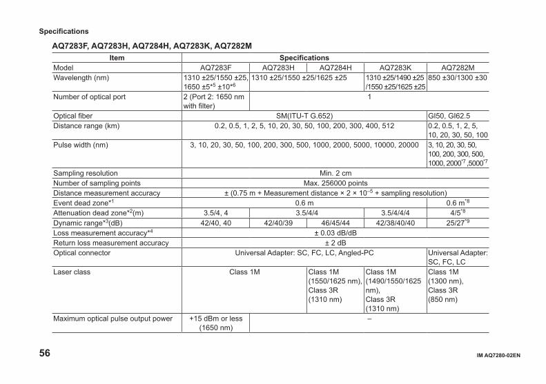
AQ7283F, AQ7283H, AQ7284H, AQ7283K, AQ7282MItem Specifications
Model AQ7283F AQ7283H AQ7284H AQ7283K AQ7282MWavelength (nm) 1310 ±25/1550 ±25,
1650 ±5*5 ±10*61310 ±25/1550 ±25/1625 ±25 1310 ±25/1490 ±25
/1550 ±25/1625 ±25850 ±30/1300 ±30
Number of optical port 2 (Port 2: 1650 nm with filter)
1
Optical fiber SM(ITU-T G.652) GI50, GI62.5Distance range (km) 0.2, 0.5, 1, 2, 5, 10, 20, 30, 50, 100, 200, 300, 400, 512 0.2, 0.5, 1, 2, 5,
10, 20, 30, 50, 100Pulse width (nm) 3, 10, 20, 30, 50, 100, 200, 300, 500, 1000, 2000, 5000, 10000, 20000 3, 10, 20, 30, 50,
100, 200, 300, 500, 1000, 2000*7 ,5000*7
Sampling resolution Min. 2 cmNumber of sampling points Max. 256000 pointsDistance measurement accuracy ± (0.75 m + Measurement distance × 2 × 10⁻⁵ + sampling resolution)Event dead zone*1 0.6 m 0.6 m*8
Attenuation dead zone*2(m) 3.5/4, 4 3.5/4/4 3.5/4/4/4 4/5*8
Dynamic range*3(dB) 42/40, 40 42/40/39 46/45/44 42/38/40/40 25/27*9
Loss measurement accuracy*4 ± 0.03 dB/dBReturn loss measurement accuracy ± 2 dBOptical connector Universal Adapter: SC, FC, LC, Angled-PC Universal Adapter:
SC, FC, LCLaser class Class 1M Class 1M
(1550/1625 nm),Class 3R (1310 nm)
Class 1M (1490/1550/1625 nm),Class 3R (1310 nm)
Class 1M (1300 nm),Class 3R (850 nm)
Maximum optical pulse output power +15 dBm or less(1650 nm)
–
Specifications
IM AQ7280-02EN 57
Item SpecificationsModel AQ7283F AQ7283H AQ7284H AQ7283K AQ7282MDimension 211 mm(W) × 110 mm (H) × 32 mm (D) (excluding projections)Mass Approx. 420gOperating conditions The same as the mainframe’s operating environment*1 Pulse width: 3 ns, Return loss: ≥55 dB, Group refractive index: 1.5, at 1.5 dB below the unsaturated peak level, Typical*2 Pulse width: 10 ns, Return loss: ≥55 dB, Group refractive index: 1.5, at a point where the backscatter level is within ±0.5 dB of the
normal level, Typical*3 Pulse width: 20000 ns, Measurement time: 3 minutes, SNR=1, Typical, Decrease by 0.5 dB with an angled-PC connector, Decrease
by 0.5 dB with /SLS option for AQ7284A, AQ7285A and AQ7284H, Typical*4 For a loss 1 dB or less, the accuracy is ±0.05 dB.*5 At 20 dB below the spectral peak of pulsed optical output, at 23˚C, after warm-up of 30 minutes*6 At 60 dB below the spectral peak of pulsed optical output, at 23˚C, after warm-up of 30 minutes*7 1300 nm only*8 Return loss condition changes to ≥40 dB.*9 Pulse width: 500 ns (850 nm)/1000 ns (1300 nm), Measurement time: 3 minutes, SNR=1, GI50, Typical
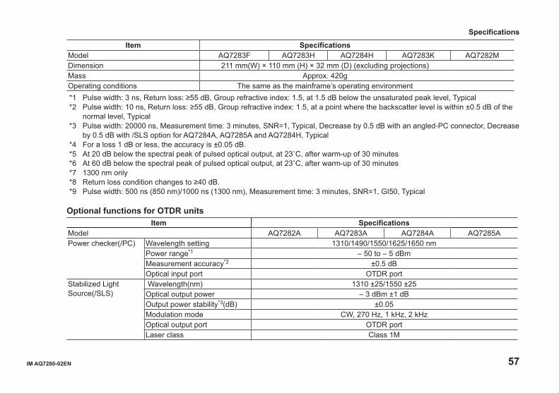
Optional functions for OTDR unitsItem Specifications
Model AQ7282A AQ7283A AQ7284A AQ7285APower checker(/PC) Wavelength setting 1310/1490/1550/1625/1650 nm
Power range*1 – 50 to – 5 dBmMeasurement accuracy*2 ±0.5 dBOptical input port OTDR port
Stabilized Light Source(/SLS)
Wavelength(nm) 1310 ±25/1550 ±25Optical output power – 3 dBm ±1 dBOutput power stability*3(dB) ±0.05Modulation mode CW, 270 Hz, 1 kHz, 2 kHzOptical output port OTDR portLaser class Class 1M
Specifications

58 IM AQ7280-02EN
Item SpecificationsModel AQ7283F AQ7283H AQ7284H AQ7283KPower checker(/PC) Wavelength setting 1310/1490/1550/1625/1650 nm
Power range*1 – 50 to – 5 dBmMeasurement accuracy*2 ±0.5 dBOptical input port OTDR port*4 OTDR port
Stabilized Light Source(/SLS)
Wavelength(nm) 1310 ±25/1550 ±25, 1650 ±5*5 ±10*6
1310 ±25/1550 ±25/1625 ±25 1310 ±25/1490 ±25/1550 ±25/1625 ±25
Optical output power – 3 dBm ±1 dBOutput power stability*3(dB) ±0.05/±0.05, ±0.15 ±0.05/±0.05/±0.15 ±0.05/±0.15/±0.05
/±0.15Modulation mode CW, 270 Hz, 1 kHz, 2 kHzOptical output port OTDR portLaser class Class 1M
Power Checker (/PC) and Stabilized Light Source (/SLS) are not available for AQ7282M.*1 CW, Safe maximum input power: 0 dBm (1 mW)*2 CW, 1310 nm, −10 dBm*3 Constant temperature, 5 minutes after warm-up of 5 minutes*4 Not applicable to Port2*5 At 20 dB below the spectral peak of pulsed optical output, at 23˚C, after warm-up of 30 minutes*6 At 60 dB below the spectral peak of pulsed optical output, at 23˚C, after warm-up of 30 minutes
Specifications
IM AQ7280-02EN 59
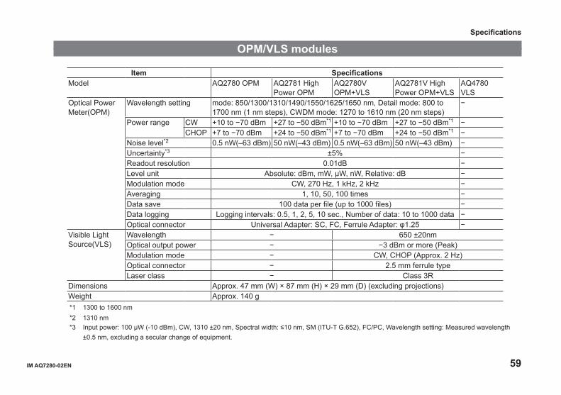
OPM/VLS modules
Item SpecificationsModel AQ2780 OPM AQ2781 High
Power OPMAQ2780V OPM+VLS
AQ2781V High Power OPM+VLS
AQ4780 VLS
Optical Power Meter(OPM)
Wavelength setting mode: 850/1300/1310/1490/1550/1625/1650 nm, Detail mode: 800 to 1700 nm (1 nm steps), CWDM mode: 1270 to 1610 nm (20 nm steps)
−
Power range CW +10 to −70 dBm +27 to −50 dBm*1 +10 to −70 dBm +27 to −50 dBm*1 −CHOP +7 to −70 dBm +24 to −50 dBm*1 +7 to −70 dBm +24 to −50 dBm*1 −
Noise level*2 0.5 nW(–63 dBm) 50 nW(–43 dBm) 0.5 nW(–63 dBm) 50 nW(–43 dBm) −Uncertainty*3 ±5% −Readout resolution 0.01dB −Level unit Absolute: dBm, mW, μW, nW, Relative: dB −Modulation mode CW, 270 Hz, 1 kHz, 2 kHz −Averaging 1, 10, 50, 100 times −Data save 100 data per file (up to 1000 files) −Data logging Logging intervals: 0.5, 1, 2, 5, 10 sec., Number of data: 10 to 1000 data −Optical connector Universal Adapter: SC, FC, Ferrule Adapter: φ1.25 −
Visible Light Source(VLS)
Wavelength − 650 ±20nmOptical output power − −3 dBm or more (Peak)Modulation mode − CW, CHOP (Approx. 2 Hz)Optical connector − 2.5 mm ferrule typeLaser class − Class 3R
Dimensions Approx. 47 mm (W) × 87 mm (H) × 29 mm (D) (excluding projections)Weight Approx. 140 g*1 1300 to 1600 nm *2 1310 nm*3 Input power: 100 μW (-10 dBm), CW, 1310 ±20 nm, Spectral width: ≤10 nm, SM (ITU-T G.652), FC/PC, Wavelength setting: Measured wavelength
±0.5 nm, excluding a secular change of equipment.
Specifications
60 IM AQ7280-02EN
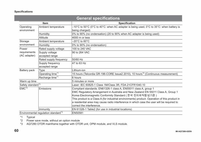
General specificationsItem Specification
Operating environment
Ambient temperature –10°C to 50°C (0°C to 40°C: when AC adapter is being used, 0°C to 35°C: when battery is being charged)
Humidity 0% to 90% (no ondensation) (20 to 90% when AC adapter is being used)Altitude 4000 m or less
Storage environment
Ambient temperature –20°C to 60°CHumidity 0% to 90% (no ondensation)
Power requirements(AC adapter)
Rated supply voltage 100 to 240 VACSupply voltageaccepted range
90 to 264 VAC
Rated supply frequency 50/60 HzSupply frequency accepted range
47 to 63 Hz
Battery pack Type Lithium-ionOperating time*1 15 hours (Telcordia GR-196-CORE Issue2 2010), 10 hours*2 (Continuous measurement)Recharge time*1 6 hours
Warm up time 5 minutes or moreSafety standard*3 Laser: IEC 60825-1 Class 1M/Class 3R, FDA 21CFR1040.10EMC*3 Emissions Compliant standards: EN61326-1 class A, EN55011 class A, group 1
EMC Regulatory Arrangement in Australia and New Zealand EN 55011 Class A, Group 1Korea Electromagnetic Conformity Standard ( 한국 전자파적합성기준 )This product is a Class A (for industrial environments) product. Operation of this product in a residential area may cause radio interference in which case the user will be required to correct the interference.
Immunity EN 61326-1 Table2 (for use in industrial locations)Environmental regulation standard*3 EN50581*1 Typical *2 Power save mode, without an option module*3 AQ7280 OTDR mainframe together with OTDR unit, OPM module, and VLS module.
Specifications

IM AQ7280-02EN 61
External Dimensions AQ7280 Mainframe (including OTDR unit and OPM/VLS module)
287 (11.30)6 (0.24) 6 (0.24)
210
(8.2
7)
80 (3.15)SIDE
If not specified, the tolerance is ±3%. However, in cases of less than 10 mm, the tolerance is ±0.3 mm.
Unit : mm (approx. inch)
Specifications
62 IM AQ7280-02EN
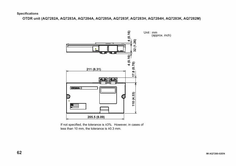
OTDR unit (AQ7282A, AQ7283A, AQ7284A, AQ7285A, AQ7283F, AQ7283H, AQ7284H, AQ7283K, AQ7282M)
211 (8.31)
205.5 (8.09)
4 (0
.16)
32 (1
.26)4
(0.1
6)11
0 (4
.33)
17.8
(0.7
0)
If not specified, the tolerance is ±3%. However, in cases of less than 10 mm, the tolerance is ±0.3 mm.
Unit : mm (approx. inch)
Specifications
IM AQ7280-02EN 63
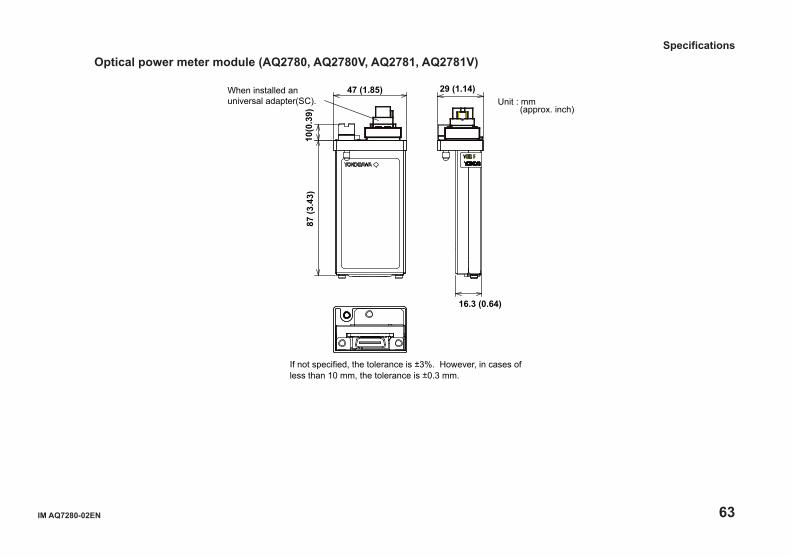
Optical power meter module (AQ2780, AQ2780V, AQ2781, AQ2781V)
VOID IF
87 (3
.43)
10(0
.39)
47 (1.85) 29 (1.14)
16.3 (0.64)
When installed an universal adapter(SC).
If not specified, the tolerance is ±3%. However, in cases of less than 10 mm, the tolerance is ±0.3 mm.
Unit : mm (approx. inch)
Specifications
64 IM AQ7280-02EN
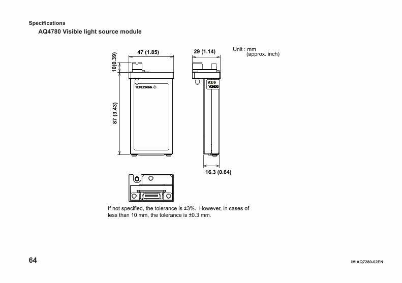
AQ4780 Visible light source module
VOID IF
16.3 (0.64)
If not specified, the tolerance is ±3%. However, in cases of less than 10 mm, the tolerance is ±0.3 mm.
Unit : mm (approx. inch)
87 (3
.43)
10(0
.39) 47 (1.85) 29 (1.14)
Specifications