Embed Size (px)
Citation preview
AQUEOUS WASTEWATER TREATMENT SYSTEM
OPERATIONS AND MAINTENANCE MANUAL
CWM Chemical Services, LLC
Model City, New York
April 2014
Revised April 2017

CWM Chemical Services, LLC Operations and Maintenance Manual
Aqueous Wastewater Treatment System Revised: April 2017
TABLE OF CONTENTS
1 INTRODUCTION .................................................................................................................. 1
1.1 GENERAL DESCRIPTION ............................................................................................ 1
1.2 PROCESS INTRODUCTION ......................................................................................... 2
2 FACILITY PROCESS DESCRIPTION ................................................................................. 4
2.1 GENERAL FACILITY DESCRIPTION ......................................................................... 4
2.1.1 Facility Description and Traffic Flow ................................................................... 4
2.1.2 Buildings, Rooms and Contiguous Areas ............................................................. 4
2.1.3 Control Room ...................................................................................................... 10
2.1.4 Main Electrical Room ......................................................................................... 11
2.1.5 Utility Room ........................................................................................................ 11
2.1.6 Laboratory ........................................................................................................... 11
2.2 UTILITIES ................................................................................................................ 12
2.2.1 Air Compressor & Air Dryer .............................................................................. 12
2.2.2 Power Distribution .............................................................................................. 12
2.2.3 Water Distribution ............................................................................................... 13
2.2.4 Motorized Roll Up Doors .................................................................................... 13
2.2.5 Steam Boilers ............................................................................................................ 13
2.3 PROCESS SYSTEMS .............................................................................................. 14
2.3.1 Tank Truck Unloading System ........................................................................... 14
2.3.2 Special Treatment System ................................................................................... 14
2.3.3 Solids Dissolving System .................................................................................... 15
2.3.4 Aqueous Receiving Blend Tanks ........................................................................ 16
2.3.5 Leachate Storage Area ........................................................................................ 16
2.3.6 Alkalization Process ............................................................................................ 18
2.3.7 Filter Presses ....................................................................................................... 19
2.3.8 Filtrate Storage Tank ........................................................................................... 19
2.3.9 Biological Treatment ........................................................................................... 20
2.3.10 Carbon and Arsenic Adsorbers ........................................................................ 20
2.3.11 Final Treated Effluent Holding Tanks ............................................................. 22
2.4 AUXILIARY SYSTEMS ......................................................................................... 22
2.4.1 Sulfuric Acid Storage ................................................................................................ 22
2.4.2 Ferrous Sulfate Storage ....................................................................................... 23
2.4.3 Lime and Calcium/Magnesium Hydroxide Storage ............................................ 23
2.4.4 Tank Venting System .......................................................................................... 23
2.4.5 Process Sumps ..................................................................................................... 25
2.4.6 Filter Ventilation System .................................................................................... 25
2.4.7 Flushing System .................................................................................................. 25
2.4.8 Agitators .............................................................................................................. 26
3 QUALITY CONTROL ......................................................................................................... 26
4 EQUIPMENT AND INSTRUMENTATION....................................................................... 26
4.1 GENERAL DESCRIPTION .......................................................................................... 26
5 START UP PROCEDURES FOR UTILITIES AND SUPPORT SYSTEMS ..................... 27

CWM Chemical Services, LLC Operations and Maintenance Manual
Aqueous Wastewater Treatment System Revised: April 2017
5.1 ELECTRIC POWER DISTRIBUTION ......................................................................... 27
5.2 INSTRUMENT/PLANT AIR SYSTEM ....................................................................... 28
5.3 BUILDING HEATING, VENTILATION & AIR CONDITIONING ........................... 29
5.4 LIGHTING AND EMERGENCY LIGHTING ............................................................. 29
5.5 PROCESS AND POTABLE WATER ........................................................................... 30
6 OPERATING PROCEDURES ............................................................................................. 32
6.1 PROCESSING SYSTEMS ............................................................................................ 32
6.1.1 Tank Truck Unloading System ........................................................................... 32
6.1.2 Unloading and Transfer to the Receiving Tanks ................................................. 35
6.1.3 Special Treatment System ................................................................................... 35
6.1.4 Leachate Storage ................................................................................................. 36
6.1.5 Solids Dissolving/Mixing Tank T-850 ................................................................ 36
6.1.6 Reaction Blend Tanks T-210, T-220 and T-230 ................................................. 37
6.1.7 Lime and Calcium/Magnesium Hydroxide Slurry Operation ............................. 37
6.1.8 Filter Press ........................................................................................................... 39
6.1.9 Biological Treatment Process Description .......................................................... 42
6.1.10 SPDES Outfall 01A ......................................................................................... 47
6.1.11 Effluent Holding Tanks T-125 and T-58 ......................................................... 47
6.1.12 Facultative Ponds 1/ 2 ..................................................................................... 48
6.2 AUXILIARY SYSTEMS ............................................................................................... 49
6.2.1 Sulfuric Acid Storage .......................................................................................... 49
6.2.2 Lime and Calcium/Magnesium Hydroxide Handling System ............................ 49
6.2.3 Caustic Scrubber T-1310 ..................................................................................... 50
6.2.4 Ferrous Sulfate Storage ....................................................................................... 52
LIST OF FIGURES
FIGURE 1. - AWTS FLOWCHART
APPENDICES
APPENDIX A - ELECTRICAL VISUAL INSPECTION
APPENDIX B - ELECTRICAL TESTING
APPENDIX C - FACILITY P&IDs

CWM Chemical Services, LLC Operations and Maintenance Manual
Aqueous Wastewater Treatment System Revised: April 2017
1
1 INTRODUCTION
1.1 GENERAL DESCRIPTION
CWM has engineered and constructed an Aqueous Wastewater Treatment System (AWTS) designed
to treat on-site waters, landfill leachate, and gate receipts from customers (see Figure 1.1). The
system occupies an area of approximately two acres, and is located at the western edge of the existing
operating facility. The facility features enclosed tanks for receipt of waste materials, reaction vessels
for the removal of inorganic contaminants from the wastes, filter presses for the removal of solids,
biotowers for the removal of soluble organics (alcohols and ketones), carbon adsorption for the
capture of residual organics, cartridge filters and adsorption media for the removal of arsenic, and
storage tanks for the treated waste. The alkalization/precipitation, lime slurry, filter press, and gate
receipts receiving operations are housed in the 10,000 square foot Aqueous Treatment (A/T)
Building along with the control room, laboratory, and offices. The 1,500 square foot Water
Treatment (W/T) Building houses the carbon adsorption and arsenic removal processes.
The system features a Programmable Logic Controller (PLC) to monitor operations and transfers of
materials within the facility. The PLC is also used to insure system safety by interlocking with
various control equipment.
The Aqueous Treatment and Water Treatment Buildings were designed to provide an
environmentally safe water treatment operation. Environmental protection and treatment flexibility
are the primary objectives in the design and operation of the facility. The system features concrete
containment surrounding all tanks, reaction vessels, and other process equipment. In addition, where
needed, process piping is lined with special corrosion resistant plastic (polypropylene) or is
constructed of High Density Polyethylene (HDPE) in order to prevent corrosion on the interior
surface of the piping and prolong the process life of the piping. Finally, process tanks within the
A/T Building are vented to carbon canisters or to the caustic scrubber depending on the tank contents.
This system controls VOCs, acid vapors and odors associated with receipt and treatment of the waste
materials.

CWM Chemical Services, LLC Operations and Maintenance Manual
Aqueous Wastewater Treatment System Revised: April 2017
2
1.2 PROCESS INTRODUCTION
The Aqueous Wastewater Treatment System is designed to treat various combinations of on-site
generated liquid waste and gate receipts. The maximum capacity through the entire system is
approximately 260,000 gallons per day.
The system is designed to be flexible in the treatment of waste streams. Flexibility is provided by
the capability to by-pass or recirculate the process flow through major components of the treatment
system. This allows for enhanced treatment, waste reduction and additional process capacity.
Leachate from SLF 1-6 typically goes through an oil/water separation step prior to treatment at the
AWTS. Oil from the bi-phased leachate is incinerated offsite. In the AWTS process, incoming
aqueous leachate, gate receipts and contaminated groundwater from the Groundwater Extraction
Systems (GWES) is pumped into the reaction/blending tanks where sulfuric acid and ferrous sulfate
are added to lower the pH and facilitate metals precipitation, as needed. Other reagents may be
added to treat the identified contaminants as needed. Gate receipts can be mixed in the special
treatment tanks and then blended with the leachate flow in the reaction/blending tanks. Each batch
of blended waste is carefully prepared and analyzed by facility chemists prior to proceeding to the
next treatment step.
The blended wastes then go through an alkalization step and filter press units to remove the
precipitate including metal contaminants. The filter cake may be incinerated offsite or transported
to the site's secure landfill depending on the F039 analysis and achievement of land ban treatment
standards. Aqueous effluent is then pumped into the biological treatment system (biotowers) where
the wastewater undergoes biodegradation to remove organics. The treated effluent is then processed
through carbon adsorption units for polishing. After carbon adsorption and depending on the arsenic
concentration, the treated effluent may be processed through cartridge filters (for fine particulate
removal) and pass through a series of tanks containing adsorption media specifically designed for
the removal of arsenic. If the arsenic concentration meets treatment standards, the arsenic treatment
process can be by-passed. Flow then passes on to the effluent holding tanks for testing prior to

CWM Chemical Services, LLC Operations and Maintenance Manual
Aqueous Wastewater Treatment System Revised: April 2017
3
discharge to the facultative ponds. The biotowers can also be bypassed if organic constituent
concentrations are low and the carbon treatment system can handle the organic load. Samples of the
effluent prior to the holding tank are collected at SPDES Outfall 01A and tested in accordance with
the facility’s SPDES permit. The final treated effluent accumulated in the facultative pond
undergoes extensive laboratory testing and once approved, is discharged to the lower Niagara River
under the facility’s SPDES permit.
Leachate from SLF 7 may be treated by adding powdered activated carbon, then lime slurry, filtration
through the filter press with the filtrate collected in a tanker truck for off-site disposal. The aqueous
leachate from SLF 1-6 may also be managed by this method.

CWM Chemical Services, LLC Operations and Maintenance Manual
Aqueous Wastewater Treatment System Revised: April 2017
4
2 FACILITY PROCESS DESCRIPTION
2.1 GENERAL FACILITY DESCRIPTION
2.1.1 Facility Description and Traffic Flow
The Aqueous Wastewater Treatment Building runs north and south, with the lab, the control room
and the operator areas occupying the northeast corner of the building (approx. 15%). The balance
of the building houses the process equipment.
The following facilities and equipment are located immediately outside the main Aqueous Treatment
Building:
south side - two bulk tanker unloading bays, unloading area for drum waste streams, lift
stations, CC blower, bio tower blower , and vapor phase carbon units.
east side - three large reaction/blending vessels, two biotowers and the entrance for truck
drivers and operating personnel.
north side - receiving area for operations and maintenance materials.
west side - the lime storage silo, filter cake transfer point and unloading area for supplies.
The traffic flow is directed in a counterclockwise direction around the facility. The approach is from
the east, then turning north along the roadway adjacent to the reaction/blend tanks. Upon arrival, the
drivers will check in with facility personnel and will be directed to the appropriate location for
spotting their vehicles.
2.1.2 Buildings, Rooms and Contiguous Areas
The Aqueous Wastewater Treatment System comprises an area of approximately 2 acres. Within
this area is the Aqueous Treatment Building with a roofed area of about 9,900 square feet. The
adjacent tank farm with the process tanks contains an approximate area of 2,725 square feet. The
remote containment area housing the filtrate storage tank T-100 and one of the final effluent storage
tanks T-125 has an approximate area of 12,700 square feet. The Water Treatment Building is located
CWM Chemical Services, LLC Operations and Maintenance Manual
Aqueous Wastewater Treatment System Revised: April 2017
5
immediately east of the Aqueous Treatment Building and has an area of approximately 1,240 square
feet.
The Aqueous Treatment Facility is comprised of these major areas:
• unloading bays
• gate receipts area
• process tankage
• reagent and alkalization process area
• filter press building
• drum storage area
• control laboratory, office and utility rooms
• light storage mezzanine
• carbon adsorption
A description of each of these areas is provided in the following sections.
2.1.2.1 Unloading Bays
The unloading area is a concrete curbed containment area with a truck unloading/loading dock,
located on the south end of the A/T Building. There are two tanker unloading stations from which
aqueous material can be transferred to the reaction blend tanks, the special treatment tanks or the
filtrate storage tank.
2.1.2.2 Receiving and Special Treatment Process Area
The receiving and special treatment process area is centrally located in the south portion of the
Aqueous Treatment Building. It encompasses approximately 2,400 square feet. This area is a
location where gate receipts can be introduced into the system. There are two pumps with basket
filters located at the unloading station within this area. From the unloading pumps, the aqueous
waste may be transferred to one of the three special treatment tanks, to one of the three receiving
tanks outside in the process tank storage area, or to the filtrate holding tank. Solid wastes may be
transferred into the treatment system after dissolving and mixing in warm water. After the lab has
analyzed samples of the inbound material, the chemical operator may transfer the material to the

CWM Chemical Services, LLC Operations and Maintenance Manual
Aqueous Wastewater Treatment System Revised: April 2017
6
appropriate tank as specified by the A/T Supervisor. The caustic scrubber is also centrally located
within this area.
The special treatment process area contains the following major process vessels and their ancillary
devices:
• Dissolving and mixing tank T-850
• Special treatment tank T-810
• Special treatment tank T-820
• Special treatment tank T-710
• Ferrous sulfate storage tank T-830 (Chemical Bulk Storage (CBS), product tank)
• Ferrous sulfate storage tank T-840 (CBS, product tank)
• Caustic scrubber tank T-1310
2.1.2.3 Process Tankage
The tank farm portion of the process tankage encompasses approximately 2,725 square feet. It is
located outside adjacent to the southeast corner of the A/T Building. This containment area houses
the three receiving tanks and the two biological treatment tanks.
• Receiving and blend tank T-210
• Receiving and blend tank T-220
• Receiving and blend tank T-230
• Biotower T-310
• Biotower T-320
Material from one, two, or all three of the special treatment tanks may be blended in the receiving
tanks according to the blend determined by the A/T Supervisor. Tankers may be unloaded into the
receiving tanks. On spec blends are then processed through the alkalization/lime slurry step. Outside,
to the northeast of the Aqueous Treatment Building, is a separate containment area surrounded by
concrete wall. This area contains two of the system's tanks:

CWM Chemical Services, LLC Operations and Maintenance Manual
Aqueous Wastewater Treatment System Revised: April 2017
7
• Filtrate storage tank T-100
• Treated effluent storage tank T-125
The filtrate storage tank T-100 holds treated filtrate that is discharged from the filter press operation
prior to processing through the biotower, carbon units, and arsenic treatment process.
Storage tank T-125, with a capacity of 394,271 gallons, is the holding vessel for final treated effluent
discharged after the carbon and/or arsenic treatment systems. Tank T-58 is also utilized as a final
treated effluent holding tank in conjunction with T-125. Tank T-58, with a capacity of 488,529
gallons, is located west of the Aqueous Treatment Building. The effluent in these tanks is sampled
and tested prior to discharge to the facultative ponds.
2.1.2.4 Reagent and Alkalization Process Area
The reagent and alkalization process area encompasses approximately 1,450 square feet. The area
is centrally located in the northwest area of the A/T Building. This area contains the following major
process vessels and their ancillary devices:
• Sulfuric acid storage tank T-910 (CBS, product tank)
• Alkalization tank T-1010
• Alkalization tank T-1020
• Lime slurry tank T-1410 (product tank)
This area is where the bulk concentrated sulfuric acid is stored for use throughout the process to
chemically adjust the pH of the inbound waste materials. The alkalization tanks are used for the
alkalization of the process solution by lime or calcium/magnesium hydroxide slurry addition. This
causes a precipitation of insoluble salts including the heavy metals in the solution. The metal
containing solids can then be removed by the filter presses.
2.1.2.5 Filter Press Building
The filter press area is a self-contained structure within the Aqueous Wastewater Treatment System.
The area encompasses about 715 square feet and it is located in the northwest corner of the A/T

CWM Chemical Services, LLC Operations and Maintenance Manual
Aqueous Wastewater Treatment System Revised: April 2017
8
Building. Within the structure is one Durco plate and frame filter press (F-1110) and one Durco
pressure leaf filter press (F-1120). The Durco pressure leaf filter press will be primarily used with
the plate and frame used as a backup or during periods of high flow and will provide filtering of the
processed wastes. The filtrate is collected and transferred to tank T-100 for storage prior to other
on-site processing s.
In the filter press area, there is an open grating second floor level allowing access to the filter presses.
The lower elevation is utilized for the filtrate handling equipment and the material handling
containers for the collection and transfer of the filter cake. The area contains the following major
process pieces of equipment and their ancillary devices:
• Filter press F-1110
• Filter press F-1120 (tank)
• Filtrate holding tank T-1111
• Filtrate holding tank T-1112
The ventilation is provided by a vent hood and wall mount fans.
2.1.2.6 Drum Storage Area
The drum storage and handling area is located in the southwest corner of the A/T Building and
encompasses approximately 1,960 square feet. This area is used to store liquid and solid waste drums
prior to treatment. Storage of miscellaneous product drums and satellite storage is also provided in
this area.
All liquid waste drums are stored on modular containment units to control leaks and spills. The
modular units are lined with a chemically resistant lining system and segregated according to drum
compatibility. Drum handling equipment is provided to transfer the drum contents into one of the
special treatment tanks or reaction/blending tanks as directed by the lab.
CWM Chemical Services, LLC Operations and Maintenance Manual
Aqueous Wastewater Treatment System Revised: April 2017
9
2.1.2.7 Control Room, Laboratory, Office and Utility Room
The control room, laboratory, office and utility room are located in a self contained structure within
the A/T Building. It houses the following rooms:
• Mechanical equipment room 15' x 29'
• Electrical room 15' x 17'
• Supervisors office 13' x 13'
• Laboratory 13' x 17'
• Process control room 13' x 21'
• Employee lunch room 13' x 10'
• Bathroom
This is the only area within the A/T Building that has an electrical classification of general purpose.
This area may contain open flames and sparking devices. The remainder of the A/T Building has an
electrical classification of Class 1, Division 2, Group D, although under current site work practices
and safety standards, it may be reviewed for a rating downgrade if so requested by the operations
department. Adequate precautions as outlined in the safety section must be adhered to at all times.
The bathroom and employee lunch room are situated just south of the laboratory. The supervisor's
office is located in the northeast corner of the building. The control room, main electrical room,
utility room and laboratory are described in Sections 2.1.3 through 2.1.6.
2.1.2.8 Light Storage Mezzanine
The light storage mezzanine is the area directly over the control room, laboratory, office and utility
room. This area is designed to be used for the storage of light office supplies and light maintenance
items. The facilities compressed air dryer system is also located in this area. The area has a
hazardous rating the same as the process area. The light storage mezzanine encompasses an
approximate area of 2,000 square feet. Its size is 30' x 64'. Also included in the mezzanine area is
the 14' x 16' air handling room which contains the air conditioning unit, blowers, and other equipment
associated with the A/T Building's HVAC systems.

CWM Chemical Services, LLC Operations and Maintenance Manual
Aqueous Wastewater Treatment System Revised: April 2017
10
2.1.2.9 Carbon and Arsenic Adsorption
The final treatment step is performed in the Water Treatment Building. Effluent from the biotowers
is transferred through the carbon adsorbers where residual organics are removed. Additional process
tankage associated with this operation is located adjacent to the W/T Building. Aqueous waste with
low contamination levels of organics may be added to T-100 and processed directly through the W/T
Building, bypassing the front part of the treatment train, as determined by Waste Approvals Manager
and/or A/T Supervisor. From the carbon adsorbers, the treated liquid may be processed through the
arsenic treatment system or sent to the final effluent holding tanks T-58 and T-125. The arsenic
treatment system contains two parallel treatment lines. Each treatment line consists of two
cartridge filters in series followed by a primary and a secondary adsorption tank in series. The two
parallel systems are piped and valved such that they can be operated individually or
simultaneously. From the arsenic adsorbers, the treated liquid is sent to the final effluent holding
tanks T-58 and T-125. SPDES Outfall 01A sampling point is located after all treatment is complete,
prior to discharge into one of the effluent holding tanks.
The W/T Building contains the following major process vessels and their ancillary devices:
Carbon adsorber T-3007
Carbon adsorber T-3008
Four cartridge filters
Arsenic Adsorption tanks T-3010 A/B/C/D
Miscellaneous small tanks for reagent addition.
2.1.3 Control Room
The control room is located inside the A/T Building in the southwest corner of the personnel area.
It is approximately 240 square feet and it contains the control panel, and an area for the operations
logs and record keeping. From the control room the operator has the ability to monitor process
conditions in the treatment plant and control functions enabling him to maintain certain process
operations. A programmable logic controller is utilized in monitoring the operations and in
activating the alarm systems.
CWM Chemical Services, LLC Operations and Maintenance Manual
Aqueous Wastewater Treatment System Revised: April 2017
11
2.1.4 Main Electrical Room
The electrical room houses the main power distribution center and the other electrical distribution
and connection centers. This includes the Motor Control Center (MCC) which contains the main
power disconnect, the disconnects for all major motors and large power consumers. There are
several lighting, control and power panel boards. A remote I/O panel for the programmable logic
controls is mounted within the electrical room along with the telephone service panel.
The electrical power is supplied by three 100 kva single phase 13.2 kv/480 vac pole transformers
and it enters the control room via an underground conduit. 440 volt power is then distributed to the
user through a General Electric Motor Control Center and 110 volt power through two "Square D"
step down transformers. The electrical room has approximately 270 square feet of area and it is
located in the northeastern corner of the facility. It is equipped with a ventilation exhaust fan to
maintain a suitable room temperature for the equipment.
2.1.5 Utility Room
The utility room is located midway through the personnel area, on the east side of the Aqueous
Treatment Building. It is approximately 450 square feet and contains the building heating plant
boiler, Sullair 100 HP air compressor, and the process water system and backflow preventer. There
are two entrances to the utility room, one from the outside of the building and the other from the
building corridor.
2.1.6 Laboratory
The lab contains the required equipment and instrumentation to perform the analysis necessary to
qualify incoming waste streams and support the processing within the AWTS. The lab contains a
four foot ventilation hood, work bench areas and a desk. Additional analysis (e.g. VOCs, metals)
is performed in the Main Laboratory.

CWM Chemical Services, LLC Operations and Maintenance Manual
Aqueous Wastewater Treatment System Revised: April 2017
12
2.2 UTILITIES
2.2.1 Air Compressor & Air Dryer
The plant air system is designed to supply clean dry air to all facility controllers and positive
displacement pumps which require air for operation. In addition, plant air may be used for cleaning
out process piping and keeping the pipelines free from freezing conditions. The variable drive, high
efficiency air compressor has a minimum capacity of 350 cfm at 100 psi. The plant air header
pressure is automatically controlled to hold a pre-set pressure by loading or unloading the
compressor as required. The piping header system transfers the air throughout the facility to the
utility stations. It is piped directly to equipment requiring air such as pumps and instrument controls.
Also included in the plant air system is a Airtek heatless desiccant type air dryer. As the air is
passed through the desiccant, the moisture in the air is adsorbed onto the desiccant. Plant air is
supplied at a nominal 110 psig with a dewpoint of -40 degrees F.
2.2.2 Power Distribution
a) Primary service is fed from an existing 13,200 volt aerial line on "M" Street south of the
facility.
b) The secondary service originates at a wood pole fifty feet from the southwest corner of the
facility. The service consists of the following:
1) Three kva pole mounted oil filled transformers arranged in a 300 kva three
phase 480/277 vac bank.
2) Kilo-watt hour meter installed on the west exterior face of the building at the
south corner. Metering transformers are located at the weatherhead.
3) Three pole 600 ampere main disconnect switch located in a 480 vac three
phase, three wire, 60 hz. Motor Control Center located in the electric room at
the northeast quadrant of the building.
4) Secondary feeder consisting of a 336.4 quadruplex aerial line running from
the pole southwest of the building to weatherheads on the southwest corner
of the building. The secondary feeder continues via eight 350 mcm

CWM Chemical Services, LLC Operations and Maintenance Manual
Aqueous Wastewater Treatment System Revised: April 2017
13
conductors in 5 inch underground conduits to the main disconnect switch.
Note that the encased buried conduits pass below a NEC Class 1, Division 2,
Group D, hazardous process area.
5) The Motor Control Center has a 600 ampere copper main bus. All pumps and
motors at the 480 vac service level are fed via fused combination motor
starters and/or fused switches located in the MCC.
6) Four 120/208 vac lighting panel boards.
2.2.3 Water Distribution
City water enters the facility at the east side of the building in the utility room via a 2 inch PVC
underground line. The city water line passes through a backflow preventer and is split into two
services. One is potable water for lavatory, sanitary, safety showers and lab use. The other is service
water for flushing and general facility use. The service water system incorporates a suction tank, a
pump and a pressure control system to supply 100 psi water to the piping system that delivers water
to all of the key areas in the facility.
2.2.4 Motorized Roll Up Doors
The A/T Building has three electrically motorized overhead roll up garage style doors. These doors
are located in the filter press area and in the north and south walls of the A/T Building. The push
button opening and closing controls are located adjacent to each of the doors. Also provided are
manual pull chains to open or close the overhead doors in the event of a power outage, or in case the
electrical controller fails.
2.2.5 Steam Boilers
Two, 1.6M BTU CleverBrooks, propane fueled steam boilers are located in the Northeast corner of
the Drum Storage and Handling Area. The boilers primary function is to supply heat to the AWTS
biological treatment system (biotowers) for the reduction of volatile organic compounds. In
addition, the boilers are used to thaw frozen pipelines, valves and tankers as needed.

CWM Chemical Services, LLC Operations and Maintenance Manual
Aqueous Wastewater Treatment System Revised: April 2017
14
2.3 PROCESS SYSTEMS
2.3.1 Tank Truck Unloading System
Inbound tank trucks are directed from the Scale to the AWTS. The driver presents the paperwork
accompanying his load to the A/T supervisor or designated laboratory personnel for review. The
driver's access to the AWTS is limited to the office area of the complex.
The truck is representatively sampled with a sampling device as per the WAP. The sample is
analyzed by the lab and approved for unloading into one of the special treatment tanks, receiving
blend tanks or filtrate storage tank.
The operator connects the discharge hose from the tanker to the incoming feed line. Proper valve
sequencing allows the liquid in the tanker to be unloaded, passing through an in-line basket strainer,
unloading pump or pump by-pass, and process piping until it reaches the approved receiving vessel.
Once the truck is unloaded, pipes and hoses are flushed, valves are closed, and the transfer is
complete. The driver is allowed to inspect his tanker. The operator disconnects the hoses, and the
driver then proceeds to the outbound scale.
A sump has been provided at the unloading station to contain/collect any spilled material. Any
material collected is pumped via process piping to one of the process vessels.
2.3.2 Special Treatment System
The three special treatment tanks may be used to campaign drummed aqueous wastes for
introduction into the AWTS. A separate pump station is used to handle drum wastes ("drum
unloading station"). The drums are moved along a roller to the pump station, which includes a wand
for removal of the liquid from the drums. Drums may also be rinsed/deconned in this area. Residual
heels may also be solubilized and pumped. Containers of water soluble salts may be dissolved in
drums and transferred into the AWTS from the drum pumping station.

CWM Chemical Services, LLC Operations and Maintenance Manual
Aqueous Wastewater Treatment System Revised: April 2017
15
The number and type of wastes to be included in a batch is determined by the A/T Supervisor. The
compatibility of the materials is confirmed by the laboratory. In general these tanks are used to
blend materials for treatment through the blend tanks and/or alkalization tanks. Alternately, they
may be used to store site generated leachate or site waters. Material may be collected in a batch in
one of these tanks for shipment to another off-site facility.
Sludges, if present, may be removed from the tanks and placed into drums. These sludges may then
be handled by other treatment or disposal options depending on their constituents. There is also
provision for sulfuric acid or other miscellaneous reagent addition in order to adjust the pH level of
the stored material and facilitate treatment, if necessary.
The process flow design for the tanks and piping is shown in the P&IDs. The levels of the treatment
tanks can be monitored on the computer. Safety equipment for the tanks includes a maximum liquid
level for the tank, which has been programmed into the computer. The feed pumps automatically
shut off when this level is reached and a high level alarm is activated ..
2.3.3 Solids Dissolving System
Waste solid material may also be accepted for treatment through the AWTS. Typically delivered in
drums, these solid wastes are dissolved and mixed in T-850, an 846 gallon tank, to create a solution
amenable for treatment. The tank is constructed of Fiberglass Reinforced Plastic (FRP), using a
Derakane 510N resin with an interior “C” glass veil and Nexus rich resin layer for corrosion
protection. The tank has a mechanically removable clear lid with access hatch, and is connected to
the AWTS tank venting system for the control of odors that may be generated from this process.
To process solid wastes, the tank is filled with clean service water from the AWTS piping system.
A steam line enters the tank through the top. Introduction of steam will heat the water and provide
rotational circulation of the tank contents. An air bubbler system is also provided for agitation. Solid
waste is poured from drums into the open top of the tank using a drum loader and grabber. Up to
ten drums of waste can be mixed in a single batch and will be solubilized at about 110-120 degrees
F. Upon visual verification that the solids have been dissolved, the contents are transferred via
vacuum truck to the reaction blend tanks for treatment through the AWTS.

CWM Chemical Services, LLC Operations and Maintenance Manual
Aqueous Wastewater Treatment System Revised: April 2017
16
Although the tank was initially installed for dissolving a sodium chlorate waste, other solid waste
materials may also be dissolved using this process after verification of the system compatibility.
The tank may also be used for blending various laboratory chemicals prior to treatment. The FRP
tank material, as well as the associated pump and piping, has excellent corrosion resistance for a
wide variety of chemical constituents.
The system can also be used for dissolving solid ferrous sulfate reagent used in the treatment process.
After this material is dissolved, it is transferred into storage tanks T-830 and T-840 for introduction
into the AWTS.
2.3.4 Aqueous Receiving Blend Tanks
There are three, 30,000 gallon agitated receiving tanks that are used to receive and blend aqueous
wastes. One tank is fabricated of fiber reinforced plastic while the other two tanks are steel and
lined in order to provide superior chemical resistance to organic and inorganic acids, oxidizing
agents, and salts. Prior to filling these tanks with aqueous wastes A/T Supervisor reviews each waste
stream to ensure chemical compatibility with the tank lining system.
Material may be added to these tanks from the unloading station, groundwater extraction system,
leachate storage tanks, special treatment (drum decant or bulking) tanks or waste solids dissolving
tank. Sulfuric acid may be transferred in from the reagent storage tank. Other miscellaneous wet or
dry reagents may be added directly to the tanks to facilitate treatment, as needed. The level of each
of the receiving tanks can be monitored on the computer. Safety features include automatic shut off
of feed pumps at a preset maximum tank level and a high level alarm on the control panel. The tanks
are provided with a pressure relief system.
2.3.5 Leachate Storage Area
The Leachate Tank Farm (LTF) provides sufficient storage capacity and transfer of leachate
collected from existing closed secure landfills (SLFs) 1-6, 7, 10, 11, 12 and landfill RMU-1, as well
as future landfills.

CWM Chemical Services, LLC Operations and Maintenance Manual
Aqueous Wastewater Treatment System Revised: April 2017
17
The facility consists of three (3) storage tanks (T-101, T-102, T-103), two (2) leachate transfer
pumps, level monitors and ancillary devices, all installed within a chemically resistant coated
concrete containment area.
A summary of the leachate storage area equipment is provided below:
a) Three (3) flat bottom tanks with a capacity of approximately 350,000 gallons each
(T-101, T-102, T-103).
b) Two (2) centrifugal process pumps for transfer of leachate to the Aqueous
Wastewater Treatment System (P-104, P-105).
c) Four (4) collection sumps, with submersible pumps, that transfer accumulated
precipitation to main containment area sump pit with submersible pump (P-108).
d) Three (3) tank level monitors, one on each tank (LIT-101, LIT-102, LIT-103).
e) Tank bottom and leachate transfer piping leak detection system.
Aqueous leachate from closed landfills SLF 1-6 is pretreated in the oil/water separator (T-158). The
aqueous phase is transferred to the leachate storage tanks via an aboveground pipeline from tank T-
158 located in the SLF 1-11 oil/water separator facility. The oil/water separator facility is located
east of the leachate tank farm. If the leachate from SLF 10 or 11 has an organic layer/skim, it may
be pretreated in a similar fashion; otherwise, leachate from these landfills is transferred to a 200
series process tank. Aqueous leachate from landfill SLF 12 is pumped to a vacuum tanker truck for
transfer to the LTF or AWT. Since this leachate does not contain oil RMU-1 leachate is pumped
from its lift station tank T-160 transferred through the RMU-1/SLF-12 Oil/Water Separator Building
via an above ground single walled pipe to the leachate storage tanks. Miscellaneous reagents may
be added to the leachate storage tanks to facilitate treatment, as needed. The levels in the leachate
storage tanks can be read on the A/T computer and are monitored by AWTS personnel daily.
The leachate is held in the storage tanks and transferred to the aqueous treatment plant on a demand
basis. Typically, aqueous phase leachate from landfills SLF 10 and 11 is transferred directly to the
reaction blend tanks for treatment through the entire AWTS process. Leachate from SLF 1-6 and
other aqueous waste from T-158 may be stored in a dedicated tank in the LTF. It may be passed

CWM Chemical Services, LLC Operations and Maintenance Manual
Aqueous Wastewater Treatment System Revised: April 2017
18
through a spent carbon bed for pre-treatment of volatile organics and then to the reaction blend tanks,
via tank T-3009, for further treatment. Leachate from the older landfills may also be pre-treated for
reduction of organics using Fenton’s reagent. SLF 7 leachate may be transferred to a process tank,
treated with powdered activated carbon, filtered tested and then shipped to CWM, Vickery for
disposal. The aqueous leachate from SLF 1-6 may also be processed in this fashion. Due to the low
level of hazardous constituents in the SLF 12 and RMU-1 leachates, they are generally transferred
to tank T-100, or directly to the water treatment facility’s carbon adsorption system. In
circumstances of heavy precipitation events, the SLF 12 and RMU-1 leachates can be directly
transferred from the leachate tank farm to tank T-3003 (lift station for carbon adsorbers) to process
the flow. Monitoring of the leachate flowing into and out of the tank farm, including the monitoring
of the tank levels, provides a means to evaluate the process and maintain accurate records.
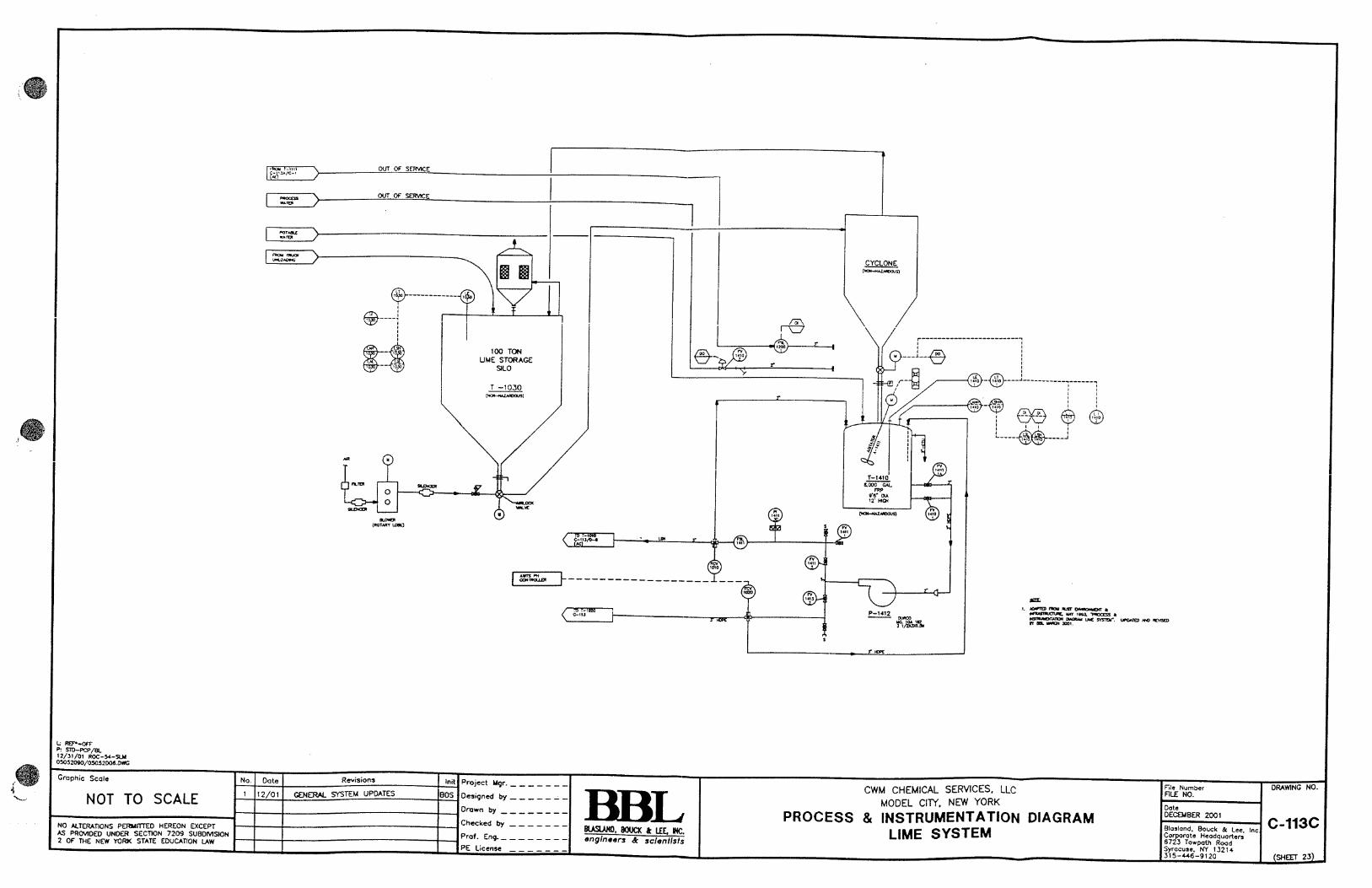
2.3.6 Alkalization Process
Lime or calcium/magnesium hydroxide is pneumatically discharged from the storage silo T-1030
into the slurry tank T-1410, which contains clean service water. Upon agitation, a slurry is produced.
The percentage of reagent in the slurry can be controlled by adjusting a timing gate on the lime
feeder. The flow rate of service water into T-1410 is controlled based on the current level in T-1410.
The slurry is added to the process liquid until a pre-determined pH is achieved (based upon material
to be processed), in order to precipitate out the metals as metal hydroxide solids, or a cyanide
precipitate.
The slurry is fed into both alkalization tanks (T-1010/T-1020) in order to ensure an alkaline waste
stream prior to filtration. The addition of slurry is controlled strictly by the pH in each alkalization
tank which can be monitored on the control panel. Temperature and level of the slurry tank, as well
as the flow to the alkalization tanks, can be controlled and monitored on the computer. The level of
the reagents in the silo is also displayed.
Process flow is introduced into the alkalization tanks T-1010 and T-1020 from the reaction blend
tanks, special treatment tanks, truck unloading station or filter press discharge. The safety features

CWM Chemical Services, LLC Operations and Maintenance Manual
Aqueous Wastewater Treatment System Revised: April 2017
19
of the alkalization process include an automatic shut off of the feed material if a preset maximum
liquid is attained in the alkalization tank.
2.3.7 Filter Presses
The one Durco plate and frame filter press and the one Durco pressure leaf filter press are used for
batch filtering of the processed aqueous waste. The slurry containing suspended metal hydroxide
solids and salts is pumped from the alkalization tanks to Filter Press No. 1 (F-1110) or No. 2 (F-
1120). The filter presses may be operated with one press in standby or both continuously to increase
process capacity. Filter Press No. 2 (F-1120) will be the primary press that will be used with Filter
Press No. 1 (F-1110) as a backup or for use during periods of higher treatment flows. The filtrate is
pumped to the filtrate storage tank T-100 via filtrate transfer tanks T-1111 and T-1112. Each press
has a capacity of approximately 75 cubic feet. When the press is full, it is opened and the solids are
dropped via a chute into a roll off box. When the box is full, the solids are sampled and tested and
either transported to the landfill for disposal or otherwise treated or disposed in accordance with land
disposal regulations. The pump pressures to the filter presses are monitored on the control panel.
Filter Press No. 2 (F-1120) is a pressure vessel and has a high-pressure alarm and shutoff. Both units
can operate concurrently when processing large volumes.
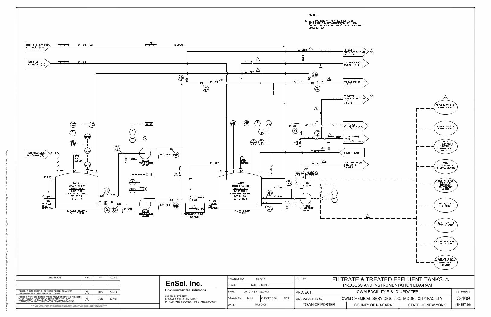
2.3.8 Filtrate Storage Tank
The filtrate storage tank T-100 has an approximate capacity of 150,000 gallons and it allows for a
buffer of storage between the alkalization/filtration processes and the treatment through the biotower
and carbon beds during periods of surge operation. Miscellaneous reagents may be added to this
tank to facilitate treatment, as needed. Wastewaters with organic contaminants may be added to this
tank for treatment through the biotowers and carbon adsorbers. The inside of the tank is coated with
Tnemec 50-330 polyura-prime and includes a cathodic protection system which is inspected
annually. The tank has high and high-high level alarms and the current volume is displayed on the
control panel. Safety features of the tank include automatic shut off of the filtrate pumps when the
preset maximum liquid level is achieved.

CWM Chemical Services, LLC Operations and Maintenance Manual
Aqueous Wastewater Treatment System Revised: April 2017
20
2.3.9 Biological Treatment
Wastewater from tank T-100 is processed through the biological treatment system. The filtrate is
pumped directly to tank T-3002 where miscellaneous reagents, nutrients, inoculum and a defoamer
can be added prior to pumping into the biological treatment unit.
The biological treatment unit consists of two biotowers (T-310 and T-320) with a total operational
capacity of 60,000 gallons. The units contain an air and water distribution system on the bottom of
the tank, a flow distributor and plastic packing. Air is supplied by either a direct drive rotary blower
or by the facility’s air compressor system.
When the tanks are operated in series, the effluent from tank T-320 overflows to a 375 gallon transfer
tank T-3012. The effluent from this tank is then pumped to tank T-310 for further biological
treatment. The biologically treated effluent from tank T-310 overflows by gravity to a 375 gallon
transfer tank T-3011 where a centrifugal pump transfers the wastewater via a 2 inch HDPE pipeline
to the carbon treatment system. Miscellaneous reagents may be added to tanks T-3011 and T-3012
to facilitate treatment, as needed. If the concentration of organics in the wastewater is high, the
effluent from the biotowers may be sent back to T-100 for additional treatment (recirculation). If
the concentration of organics in the wastewater is relatively low, the biotowers can be by-passed
with the carbon adsorption system handling the organic load.
The biotowers are vented through the overflow piping into tanks T-3011 and T-3012. When
processing Subpart CC material, these tanks are kept under a negative pressure by a 5 horsepower
rotary blower or an air compressor. Tanks T-3011 and T-3012 are equipped with emergency vacuum
relief vents. The air which is removed from tanks T-3011 and T-3012 is passed through one or two,
2,000 or 3,000 pound carbon adsorption units, in series, to remove any organic emissions from the
system. The carbon unit is replaced as needed.
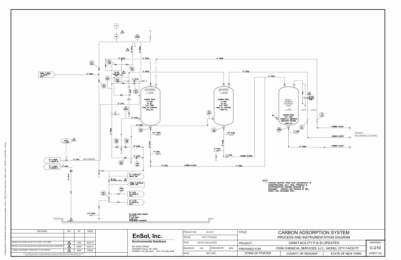
2.3.10 Carbon and Arsenic Adsorbers
Biologically treated effluent is processed through the carbon treatment system located in the Water
Treatment (W/T) Building. The liquid is pumped from the biotowers to tank T-3003.
Miscellaneous reagents may be added to tank T-3003 to facilitate treatment, as needed. The liquid

CWM Chemical Services, LLC Operations and Maintenance Manual
Aqueous Wastewater Treatment System Revised: April 2017
21
is pumped from tank T-3003 through two carbon vessels, normally arranged in series, each
containing approximately 20,000 pounds of activated carbon. The two carbon vessels can also be
operated independently or in parallel depending on the degree of treatment required. Organic
contaminants in the wastewater are removed by adsorption onto the carbon. Chemical metering
pumps may be used to inject a hexametaphosphate mixture at various points in the system to reduce
bridging in the carbon beds.
Organic loading of the carbon is monitored by analysis of the effluent. When organics are indicated
in the effluent of the primary carbon bed, it is monitored closely and the system is taken off line prior
to acetone being present in the effluent of the polish bed at a level that could produce a batch that
would fail to meet the LDR standard. The spent carbon is replaced with a fresh load of carbon. The
spent carbon is typically returned to the carbon supplier for regeneration.
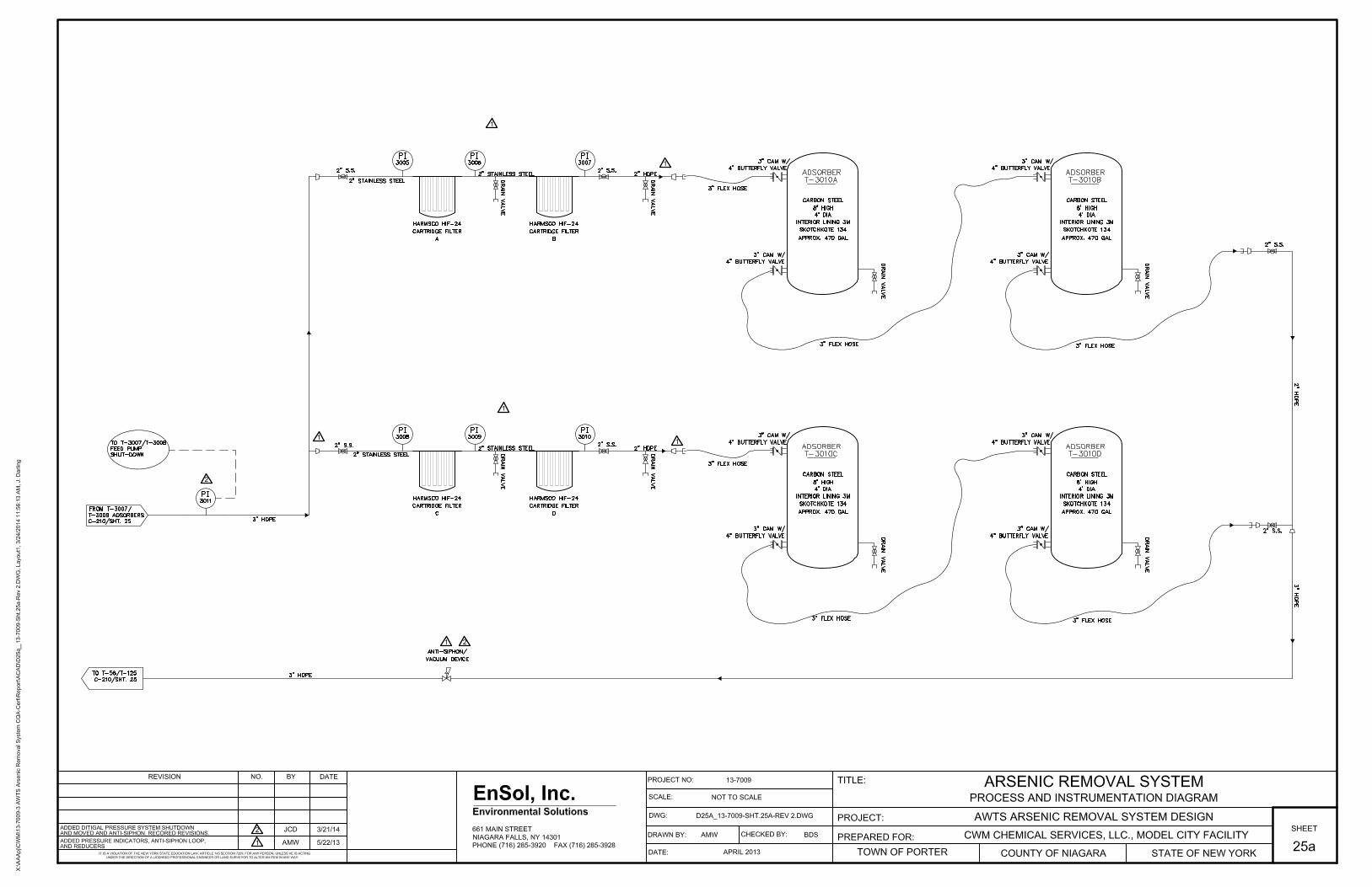
After organic removal by the carbon adsorbers, the treated effluent may be processed through the
arsenic treatment system. The arsenic treatment system contains two parallel treatment lines. Each
treatment line contains two cartridge filters in series to remove fine particulate solids to less than
5 microns. After the cartridge filters, the liquid is transferred to a primary and a secondary arsenic
adsorption tank piped in series. The arsenic tanks contain a special media designed specifically for
the removal of arsenic. The two parallel systems are piped and valved such that they can be
operated individually or simultaneously. From the arsenic adsorbers, the treated liquid is sent to
the final effluent holding tanks T-58 and T-125. The arsenic treatment system may be by-passed
if the arsenic concentration in the treated effluent, after carbon adsorption, is low and does require
additional arsenic removal.
Arsenic loading of the adsorbers is monitored by routine sampling and analysis. When the removal
efficiency is no longer acceptable, the spent arsenic media is replaced with fresh media. The spent
arsenic media is qualified for off-site disposal.

CWM Chemical Services, LLC Operations and Maintenance Manual
Aqueous Wastewater Treatment System Revised: April 2017
22
2.3.11 Final Treated Effluent Holding Tanks
Treated wastewater from the carbon and arsenic treatment systems flows into tank T-125 or T-58 for
testing prior to discharge. The tanks allow for a buffer prior to discharge should a possible upset
occur with any of the treatment unit processes. Miscellaneous reagents and/or air may be added to
facilitate treatment, as needed. The inside of tank T-125 is coated with Tnemec 50-330 polyura-
prime and includes a cathodic protection system which is inspected annually. Tank T-58 is
constructed of glass fused to steel material and also has a cathodic protection system which is also
inspected annually. If tank T-125 or T-58 wastewater does not meet the criteria for discharge to the
fac pond, it may be recirculated through the carbon and/or arsenic adsorption units and/or biotowers,
or reprocessed through the entire system.
When approved for discharge, tanks T-125 and T-58 are pumped to Facultative Ponds 1 and 2, with
subsequent transfers to Facultative Pond 3, for storage and prequalification of the effluent for
eventual offsite discharge to the Niagara River under the facility’s SPDES permit.
2.4 AUXILIARY SYSTEMS
2.4.1 Sulfuric Acid Storage
Sulfuric acid with a concentration of >75% is stored in a 8,000 gallon carbon steel tank T-910 and
used for pH adjustment in the receiving blend tanks. Tank T-910 is registered under the Chemical
Bulk Storage (CBS) regulations. Acid is unloaded from a tank truck into T-910 using air pressure.
The liquid level in the tank is displayed on the control panel and at the unloading station. The tank
has a high level alarm. The tank is vented to allow normal breathing and to prevent the dangerous
pressure build-up due to the small amount of hydrogen generated by the action of the acid on the
steel. As hydrogen is flammable, potential sources of ignition must be excluded from this area. Care
must be exercised when operating near the tank as sulfuric acid is very corrosive to the skin and
causes severe skin burns.

CWM Chemical Services, LLC Operations and Maintenance Manual
Aqueous Wastewater Treatment System Revised: April 2017
23
2.4.2 Ferrous Sulfate Storage
Liquid ferrous sulfate, with an approximate 5% concentration of iron, is stored in two 2,000 gallon
carbon steel storage tanks, T-830 and T-840, within the A/T Building. They are registered under the
Chemical Bulk Storage (CBS) regulations. The tanks are lined with a chemically resistant coating
Plasite 4310. The tanks are filled from a self pressurized tanker or from tank T-850. The liquid level
in each of the tanks is monitored by a level indicator in the AWTS control room and at the unloading
station. Each tank has high and high-high level alarms which are activated when the preset
maximum level is reached. Liquid ferrous sulfate is metered to the receiving blend tanks by a batch
controller process. The volume of ferrous sulfate to be added is specified on the process batch sheet
and programmed into the AWTS computer. The pump is then manually activated to begin the
transfer. Shutdown of the pump is triggered by the AWTS computer when the programmed volume
of ferrous sulfate is delivered.
2.4.3 Lime and Calcium/Magnesium Hydroxide Storage
Tank T-1030 is an 80 ton carbon steel silo utilized for storage of lime or calcium/magnesium
hydroxide for the metals precipitation process. The reagent is delivered to the AWTS by a pneumatic
tanker. A collection baghouse is located on top of the silo to prevent fugitive dust emissions to the
atmosphere. A mass-based level indicator is located on the silo to monitor the level. The reagent is
pneumatically transferred from the silo to tank T-1410 where the slurry is prepared for use in the
alkalization tanks.
2.4.4 Tank Venting
The AWTS has a caustic scrubber system for acid vapor neutralization. When acid waste is being
processed, the caustic scrubber tank T-1310 is filled with a dilute caustic soda (sodium hydroxide)
solution. It has a total capacity of about 580 gallons. The caustic solution is circulated through the
venturi of the caustic scrubber by the caustic scrubber pump. This creates intimate contact with the
incoming gases. Any, acid mists, or particulate matter are exposed to the caustic solution. The result
is that the incoming acid gases are neutralized, and some removal of particulates and condensables
occurs. The scrubbed gases are discharged to the atmosphere above roof level. The caustic scrubber
system is maintained under a negative atmospheric pressure by the caustic scrubber fan. This

CWM Chemical Services, LLC Operations and Maintenance Manual
Aqueous Wastewater Treatment System Revised: April 2017
24
provides a constant draw on the process vessels connected to the scrubber system header. The vapors
from the following tanks may be treated in the scrubber system:
Special treatment tanks T-810, T-820, T-710 (optional)
Receiving/blend tanks T-210, T-220, T-230 (optional)
Alkalization tanks T-1010, T-1020 (optional)
Filtrate tanks T-1111, T-1112 (optional)
Dissolving and mixing tank T-850 (optional)
Ferrous sulfate tanks T-830, T-840 (CBS product tanks)
The level of the liquid in the scrubber is displayed on the control panel. The pH and condition of the
scrubber solution must be checked periodically by the lab, and additions of caustic or replacement
of the bath must be performed as needed. When a bath is spent, it is transferred to the alkalization
tanks of the metals precipitation process.
Alternately, receiving/blend tanks T-210, T-220 and T-230, special treatment tanks T-710, T-810
and T-820 and alkalization tanks T-1010 and T-1020 are switched from the caustic scrubber system
to carbon canisters when processing aqueous waste with greater than 500 ppm volatile organics.
This includes the aqueous leachate from SLFs 1-6, 7, 10 and 11. As required by 40CFR
264/265.1080-1091, Subpart CC, these tanks are then vented through carbon adsorption canisters.
Filter Press Tank F-1120 is a pressure vessel during operation. All drained liquids and air venting
during system operation is entirely kept within the system by returning them to the feed /alkalization
tanks T-1010 and T-1020.
The biotowers, T-310 and T-320, have air bubbled through them and a steam loop provides heat
during the colder temperatures. The biotowers are vented through the overflow piping into tanks T-
3011 and T-3012. When processing Subpart CC material, these tanks are kept under a negative
pressure by a 5 horsepower rotary blower or an air compressor. Tanks T-3011 and T-3012 are
equipped with emergency vacuum relief vents. The air which is removed from tanks T-3011 and T-
3012 is passed through one or two, 2,000 or 3,000 pound carbon adsorption units, in series, to remove

CWM Chemical Services, LLC Operations and Maintenance Manual
Aqueous Wastewater Treatment System Revised: April 2017
25
any organic emissions from the system. The air exiting the carbon unit is monitored and the carbon
unit is replaced as needed.
The potential air emissions and the controls employed are included in the Air State Facility Permit,
DEC ID: 9-2934-00022/00233, issued by NYS DEC on October 24, 2014.
2.4.5 Process Sumps
Inside the A/T Building, there are two sump areas which are equipped with electrically operated
submersible pumps and hard piping. An additional sump is located in the drum handling area, which
does not require any permanent piping arrangement. Outside the A/T Building there are several
locations where the site water is collected and pumped into the process system. Each sump is
equipped with piping and quick connect fittings so that a portable submersible pump can be utilized
to remove accumulations of water as required. A majority of the outside piping is insulated to protect
it from freezing.
2.4.6 Filter Press Ventilation
The filter press area of the A/T Building is equipped with ventilation The roll off box containing
filter cake is tarped between drops and while it awaits transfer. The ventilation consists of a vent
hood and exhaust fan located in the North wall of the filter press area. Filter Press No. 2 (F-1120)
does not vent during normal operation. All drained liquids and air venting during system operation
is entirely kept within the system by returning them to the feed/ alkalization tanks T-1010 and T-
1020, which are themselves vented to a carbon canister.
2.4.7 Flushing System
The flushing system employs the same two inch piping system used to distribute process water. The
piping is routed to all of the pumping areas inside the A/T Building. It is terminated with a two inch
valve and flex hose in each user area. When a process transfer is complete, it is standard operating
procedure to flush all equipment and piping used in the transfer with clean water. This is
accomplished by connecting the flex hose to the appropriate flush connection point, opening all
required valves and flushing for the specified amount of time.
CWM Chemical Services, LLC Operations and Maintenance Manual
Aqueous Wastewater Treatment System Revised: April 2017
26
2.4.8 Agitators
Most of the process tanks are equipped with agitators. The agitators are top mounted, have three
blades and are chemically resistant to prevent corrosion. The agitators are necessary to obtain a
homogeneous mixture in the tanks and to help keep the solids in suspension. Several of the tanks
and agitators have low level controls which will automatically shut off the agitators if the liquid level
in the tank is too low.
3 QUALITY CONTROL
The analysis of the constituents in the raw waste and the monitoring of the individual process steps
and of the treated effluent are performed as required by the Site Waste Analysis Plan, Attachment C
of the Sitewide Part 373 permit.
4 EQUIPMENT AND INSTRUMENTATION
4.1 GENERAL DESCRIPTION
CWM utilizes many different types of pumps, agitators, instruments and controls to operate the
Aqueous Wastewater Treatment System. Several types of pumps include:
* electrically operated centrifugal pumps
* air operated diaphragm pumps
* metering pumps
* electric submersible pumps
* electrically operated trash pumps
Instrumentation and controls include:
* flow meters
* control valves

CWM Chemical Services, LLC Operations and Maintenance Manual
Aqueous Wastewater Treatment System Revised: April 2017
27
* pH probes
* variable speed drives
* level indicators
* pressure and temperature sensors
* conductivity probes
Due to the vast majority of equipment available, its complexity, and a constant requirement to update
equipment with new and improved components, a comprehensive list of all operating equipment is
not included within this manual. Please refer to the Site Wide Part 373 permit, Exhibit D
(Supplement to Module IV – Tanks), for complete listing of all permitted process tankage.
5 START UP PROCEDURES FOR UTILITIES AND SUPPORT
SYSTEMS
5.1 ELECTRIC POWER DISTRIBUTION
Caution: Do not proceed with any tests without first verifying that all lines, transformers, and
equipment are not energized and if previously energized under temporary power conditions, that all
equipment has been safely de-energized and discharged.
a) Primary service
1) Caution: Do not proceed with this step until the entire secondary distribution system
has been tested and verified ready as detailed here-in, including Appendix A "Visual
Inspection" and Appendix B "Testing".
b) Secondary service
1) Obtain nameplate data for the transformers from maintenance and engineering
records and verify that the size agrees with that specified on the drawings.
2) Perform a visual inspection of the portion of the work done by the utility company
and insure the following:
* no oil leaking from pole mounted transformers.
* pole area backfilled and properly guyed.
CWM Chemical Services, LLC Operations and Maintenance Manual
Aqueous Wastewater Treatment System Revised: April 2017
28
* aerial lines installed free and clear of obstructions, such as cranes etc.
3) Check to verify that secondary cables have been terminated at the aerial connection
point and at the main disconnect switch in the MCC.
4) Perform all checks per attachments Appendix A "Visual Inspection" and Appendix
B "Testing".
5.2 INSTRUMENT/PLANT AIR SYSTEM
The air system consists of a 100 hp Sullair compressor. The equipment is located in the utility room.
It is capable of supplying a minimum of 350 cfm of dry air at 100 psig to the facility users.
a) Start up and operation of Sullair compressor
1) Inspect unit for any visible signs of problems such as oil leaks, bad pressure gauges
or dirty filters.
2) Verify that all appropriate valves throughout the system have been opened before
starting the compressor. Note: Starting a rotary screw compressor without opening
a valve to relieve the pressure can damage the equipment.
3) Verify that the 110v and 440v electrical system is energized.
4) Notify all operations personnel who may be affected, of your intention to start up the
compressor.
5) Start the compressor by pushing the start button on the local control panel.
6) Listen to and observe the compressor's operation for a few moments to verify that all
systems are operating well and that the automatic controls have taken over.
b) Shut down of Sullair compressor
1) Notify all operations personnel who may be affected, of your intention to shut down
the compressor.
2) Stop the compressor by pushing the stop-reset button on local control panel.
3) Listen and observe for a few moments to ascertain that the system has shut down and
that no problems have developed.
4) Close all appropriate valves.
Note: For emergency shut down, push the stop-reset button on the local control panel.
CWM Chemical Services, LLC Operations and Maintenance Manual
Aqueous Wastewater Treatment System Revised: April 2017
29
c) Operation of the AirTek air drier
1) Inspect the unit for any visual signs of problems.
2) Verify that the 110v electrical power is energized.
3) Check that all appropriate valves are open.
Note: This system is fully automatic and once it is energized, it requires only routine checks
to verify proper operation and scheduled maintenance.
5.3 BUILDING HEATING, VENTILATION & AIR CONDITIONING
Refer to maintenance manual for information on these subjects.
5.4 LIGHTING AND EMERGENCY LIGHTING
a) Perform all procedures in Section 5.1 before proceeding.
b) Before the system is energized perform an insulation resistance test on at least three random
cables in the lighting system.
c) Check to see that all light fixtures have been lamped, and that all globes, guards and
hardware, etc., have been properly installed.
d) Perform a visual inspection of all lighting panel boards and equipment per Appendix A.
e) Check all receptacle circuits for proper grounds and that all cover plates are secured.
f) Check to see if outdoor photoelectric control faces north.
g) After giving adequate notice to all on-site personnel and contractors, energize the lighting
system.
1) Switch the lighting panel board circuit breaker for the circuit to be tested "on". It is
suggested that only one circuit be tested at a time.
2) The fluorescent lamps for the tested circuit should ignite and come up to full
brilliance immediately, at normal operating temperatures of about 65 to 70 degrees
F. Check all fixtures for faulty ignition and flickering as well as for smoking ballasts.
If any of these signs are indicated, turn off the respective circuit breaker and have the
problem corrected before re-energizing that circuit. Proceed to test each succeeding
circuit in like fashion.

CWM Chemical Services, LLC Operations and Maintenance Manual
Aqueous Wastewater Treatment System Revised: April 2017
30
3) Check the self contained emergency lighting power station unit paying particular
attention to all of the items listed and described in the "Holophane Installation and
Maintenance Manual".
• Simulate a loss of normal ac power and verify successful operation of designated
emergency lights.
• Time the transfer to emergency lights to verify that transfer took place in 10
seconds or less.
• Restore normal AC power and verify that emergency lights extinguish and that
normal AC lights are restored to operation.
4) Check the operation of the outdoor light fixtures.
• Place the outdoor lighting control switch in the "hand" position. Check to see if all
outdoor lights are lit.
• Check for incorrect ignition and flickering as well as for smoking ballasts. If any
of these signs are noted turn off the respective circuit breaker and have the problem
corrected before re-energizing that circuit.
• Insure that all outdoor lights return to off when control switch is returned to the
"off" and "auto" positions.
• Verify operation of the photoelectric control.
5) Check that no circuit breakers or other piece of lighting equipment is running hot.
5.5 PROCESS AND POTABLE WATER
City water, after entering the facility, is split into two services and it passes through two independent
flow meters. The potable water service flows through a piping system that supplies the lavatory,
safety showers and laboratory.
a) The process water system includes a backflow preventer, isolation tank T-1910, level control
valve and pump P-1901.
b) Start up
1) Open the inlet valve off the water line into tank T-1910 and fill the tank.
2) Notify all operating personnel of your intention to start the process water system.

CWM Chemical Services, LLC Operations and Maintenance Manual
Aqueous Wastewater Treatment System Revised: April 2017
31
3) Open all appropriate valves and start pump P-1901.
4) Verify that the system operating pressure is up to 50 psi.
c) To shut down the system, reverse the steps described above.
CWM Chemical Services, LLC Operations and Maintenance Manual
Aqueous Wastewater Treatment System Revised: April 2017
32
6 OPERATING PROCEDURES
This section describes the typical operating procedures for the various AWTS systems. Minor
modifications to these procedures are allowed as needed. In addition to the following procedures,
CWM requires that each new operator undergo 60 working days of on the job training with a
qualified chemical operator. Also, to become a qualified chemical operator, the trainee must pass a
written and oral examination which includes knowledge of the system, understanding of chemistry
equipment processes, material sampling procedures, and process trouble shooting.
6.1 PROCESSING SYSTEMS
6.1.1 Tank Truck Unloading System
6.1.1.1 Receiving Inbound Tank Trucks
a) Inbound tank trucks will be weighed at the inbound scale and proceed to AWTS,
accompanied by a waste tracking form.
b) Drivers will secure their trucks in the designated parking area on the south side of
AWTS and set the parking brake. The operator will chock the rear wheels of the
truck in both directions of travel. The driver will enter the personnel door and present
their paperwork to the laboratory personnel.
c) Lab personnel will review the Waste Profile, the Waste Management Decision
(WMD) and the paperwork for possible manifest discrepancies, determine the nature
of the waste material (oxidizer or reducer), any special sampling or safety
requirements and note this information on the Waste Tracking Form (WTF) and
notify the supervisor.
6.1.1.2 Sampling Inbound Tank Trucks (See also SDP 2003)
a) The operator will review the WTF and profile information and note the type of waste
being sampled, and any special precautions involved in handling the waste.
b) Personal protective equipment will be worn during all sampling and unloading activities.
When accessing top tanker, operator must wear body harness, safety lanyard, and be
connected to fall restraint system.

CWM Chemical Services, LLC Operations and Maintenance Manual
Aqueous Wastewater Treatment System Revised: April 2017
33
c) To sample, access the sampling location on top of the truck from the truck ladder.
d) Release the pressure in the tanker by opening the relief valve at the top hatch, if tanker is
so equipped. If not, slowly open the hatch wing nuts to vent the pressure.
e) Fully open the top hatch, using caution to be sure that the pressure has been equalized.
f) Using a Coliwasa, obtain a pint size sample (or otherwise specified quantity) of the waste
that is representative of the material in the tanker (see SDP 2003 for details on sampling
and sample management).
g) Dispose of the Coliwasa in the container provided.
h) Deliver the sample to the lab for analysis as specified in Section 3.0.
i) Close the sampling hatch and secure.
j) Before proceeding to unload, the operator will wait for the results of the lab analysis of
the waste, including the compatibility assessment. The lab will determine whether the
material will be accepted or rejected. If the material is "on spec", it will be unloaded as
per Section 6.1.2, into the receiving vessel specified by the lab. However, if the material
is found unacceptable for treatment in the AWTS, it may be rejected and would be sent
back to the scalehouse for return to the generator or offsite shipment to an alternate
treatment or disposal facility.
6.1.1.3 Unloading Inbound Tank Trucks via Pump
a) Open the top hatch slowly, allowing pressure to equalize. Release the wing nuts and
flip the hatch open.
b) Select a product discharge hose of suitable size. Remove the end caps and connect
one end to the tanker's product discharge valve, and the other end to the incoming
feed line. Lock the ears securely.
c) Open the product discharge valve(s).
d) Follow the procedures outlined in Sections 6.1.2 or 6.1.3 to transfer the material to
the appropriate tank.
e) When the transfer is complete, as evidenced by a visual inspection of the tank truck,
close the product discharge valve(s). Allow the driver to inspect the tanker. Follow
the established flushing procedures for the hose(s).
CWM Chemical Services, LLC Operations and Maintenance Manual
Aqueous Wastewater Treatment System Revised: April 2017
34
f) Disconnect the product discharge hose, replace all end caps.
g) Close and secure the top hatch.
h) Remove wheel chocks and store in designated area. Return the paperwork to the
driver.
i) The driver will then pull out of the unloading station and proceed directly to the
outbound scale.
j) The laboratory or AWTS supervisor will complete the transfer section of the WTF,
computerized Waste Tracking (WT) and the transfer log.
6.1.1.4 Unloading Inbound Tank Trucks via Pressurized Air
a) Connect the plant air supply hose to the air inlet on the tanker.
b) Select a product discharge hose of suitable size. Remove the end caps and connect
one end to the tanker's product discharge valve, and the other end to the incoming
feed line. Lock the ears securely.
c) Open the product discharge valve(s).
d) Follow the procedures outlined in Sections 6.1.2 or 6.1.3 to transfer the material to
the appropriate tank.
e) Use only the regulated air supply to unload tankers. Do not allow the pressure to
exceed 15 psi.
f) When the transfer is complete, as evidenced by a visual inspection of the tank truck,
close the product discharge valve(s). Allow the driver to inspect the tanker. Follow
the established flushing procedures for the hose(s).
g) Disconnect the product discharge hose, replace all end caps.
h) Close and secure the top hatch.
i) Remove wheel chocks and store in designated area. Return the paperwork to the
driver.
j) The driver will then pull out of the unloading station and proceed directly to outbound
scale.
k) The laboratory or shift supervisor will complete the transfer section of the WTF,
computerized Waste Tracking (WT) and the transfer log.

CWM Chemical Services, LLC Operations and Maintenance Manual
Aqueous Wastewater Treatment System Revised: April 2017
35
6.1.2 Unloading and Transfer to the Receiving Tanks
a) Check the liquid level and the remaining capacity in the reaction/blend tank via the
readout on the control panel.
b) Start unloading pump. Monitor pump rate by level increase in the reaction/blend
tank, which is indicated on the control panel.
c) Monitor filter for plugging problems based on the rate of flow.
d) When transfer is complete, stop pump. Close all valves. Follow established
flushing procedure.
6.1.3 Special Treatment System
6.1.3.1 Transferring Tankers from Front Unloading Station into Special Treatment Tanks T-810, T-820 and T-710
a) Check the level and remaining capacity in the designated special treatment tank.
b) Prior to any pump start-up, ensure that all appropriate valves are positioned properly.
c) Follow the established unloading procedure outlined in Section 6.1.1.
d) Start up pump. Monitor pump rate by level increase in the special treatment tank,
which is indicated on the control panel.
e) Monitor filter for plugging problems based on the rate of flow.
f) When transfer is complete, stop pump follow established flushing procedure. Close
all valves.
g) Return all valves to their original positions.
6.1.3.2 Transfer from Special Treatment Tanks T-810, T-820 and T-710 to Reaction Blend Tanks T-210, T-220 and T-230
a) Check the levels and remaining capacity in reaction/blend tank.
b) Prior to any pump start-up, ensure that all appropriate valves are positioned properly.
c) Start pump P-801, or P-802. Monitor level in reaction/blend tank.
d) When transfer is complete, stop pump, and close all valves.
e) After transfer is completed from specified tank, follow established flushing
procedure.

CWM Chemical Services, LLC Operations and Maintenance Manual
Aqueous Wastewater Treatment System Revised: April 2017
36
6.1.4 Leachate Storage
6.1.4.1 Transfer of Leachate from Landfill Leachate Storage Tanks T-101, T-102 and T-103 to Reaction Blend Tanks T-210, T-220 and T-230 or Tank T-3003
a) Check the level and remaining capacity in the reaction/blend tank or tank T-3003.
b) Prior to any pump start-up, ensure that all appropriate valves are positioned properly.
c) Start pump P-104 or P-105. Monitor level in the reaction blend tank or tank T-3003
on the control panel. Turn on the agitator, where necessary, when sufficient amount
of liquid is present.
d) When transfer is complete, stop pump, and close all valves.
e) After all transfers completed from specified tank, follow established flushing
procedure.
f) Alternately, leachate may be transferred by vacuum truck from the Leachate Tank
Farm to the process tanks
6.1.5 Solids Dissolving/Mixing Tank T-850
6.1.5.1 Dissolving and Mixing of Solid Wastes
a) With tank T-850 empty, open the process water valve and add approximately 250
gallons of clean service water to the tank.
b) When steam is available during winter months, open steam valve to heat the water to
110-120 degrees F.
c) Using the drum loader and grabber, add 6 to 10 drums of solid material. In summer
months, the number of drums is less because the water is cooler.
d) Open the air supply valve to the submerged bubbler system and agitate the tank until
a homogeneous solution is obtained.
e) Complete transfer section of WTF and computerized WT.
6.1.5.2 Transfer of Solution from Solids Dissolving/Mixing Tank T-850 to Reaction Blend Tanks T-210, T-220 and T-230 or SLF 12 Lift Station Tank T-150

CWM Chemical Services, LLC Operations and Maintenance Manual
Aqueous Wastewater Treatment System Revised: April 2017
37
For transfers to reaction/blend tanks, ensure that the receiving tank has sufficient capacity to
accept the batch and that all valves are properly positioned. Start up pump and empty the
contents of the tank.
6.1.6 Reaction Blend Tanks T-210, T-220 and T-230
After the reaction/blend tanks have been filled as described in the previous sections, continue to
agitate the material for approximately 10 more minutes to ensure complete mixing. Take
representative samples of each tank of liquid and turn in to the laboratory for analysis. Add quantities
of sulfuric acid, ferrous sulfate and other reagents determined by the laboratory as described in
Section 6.2 and continue agitation. When thoroughly mixed, transfer the specified amounts from
the reaction/blend tanks to the alkalization tanks.
6.1.7 Lime and Calcium/Magnesium Hydroxide Slurry Operation
6.1.7.1 Preparation of Slurry
a) Fill slurry tank (T-1410) with plant water (by opening valve FV 1410-2).
b) Deliver appropriate quantity of dry powdered reagent from the storage silo, MH-
1030, via its rotary lobe blower.
c) Ensure that the agitator in T-1410 (A-1411) is operating.
6.1.7.2 Transfer of Material from Reaction Blend Tanks T-210, T-220 and T-230 to Alkalization Tanks T-1010 and T-1020
a) Check the level and remaining capacity in alkalization tank T-1010 or T-1020.
b) Check that at least one (1) filter press, either F-1110 or F-1120, is ready to receive
material (if operating in continuous mode).
c) Prior to any pump start-up, ensure that all appropriate valves are positioned properly.
d) The pH controller set point should be set using the control panel interface to the
desired value, typically around 9-11 pH units, as determined by the laboratory.
Whenever the flow into the alkalization tanks, T-1010 and T-1020, drops to a

CWM Chemical Services, LLC Operations and Maintenance Manual
Aqueous Wastewater Treatment System Revised: April 2017
38
minimum, or "no-flow", condition, the pH controller is automatically closed and the
output to the valve drops to 0%.
e) Check the fluid level in the slurry tank, T-1410, to ensure that adequate slurry is
available. Start slurry pump P-1411.
f) Start pump P-201, P-202 or P-203.
g) Confirm that the pH controller has been placed in "automatic" and is controlling the
addition of slurry from T-1410.
h) Refer to the operation of the filter presses, F-1110 and F-1120. One of these must
be placed "on-line" within five minutes of starting the feed to a prefilled
alkalization tank, T-1010 or T-1020 (if operating alkalization vessel in continuous
mode).
i) Monitor the level in T-1010 and T-1020 on the control panel. Monitor temperature
using the sensors located on the tanks. Turn on the agitator, A-1011 or A-1021, when
the level in T-1010 or T-1020 is adequate to completely cover the lower blades of the
agitator.
j) When the transfer is complete, the pump will automatically stop due to low, or "no-
flow", in the discharge line. The pH controller must be placed in manual. Close all
valves that were open.
k) After all transfers are completed from the specified tank, follow established flushing
procedures.
6.1.7.3 Movement of Material from Alkalization Tanks T-1010 and T-1020 to the Filter Presses
a) This activity must be coordinated with the operation of the alkalization tank and feed
to the filter press.
b) Prior to any pump start-up, ensure that all appropriate valves are positioned properly.
c) Start pump P-1101, P-1102 or P-1103 and continue with Section 6.1.8, operation of
the filter press.
d) When all the material has been processed, stop the pump and close all valves.
e) Follow the established flushing procedure.

CWM Chemical Services, LLC Operations and Maintenance Manual
Aqueous Wastewater Treatment System Revised: April 2017
39
6.1.8 Filter Press
6.1.8.1 Filter Press Process Description
The filter press system is used to remove precipitated metal salt sludges, etc., from the neutralized
effluent. The separated solid filter cake material is trucked in roll-off boxes directly to the on-site
landfill or otherwise treated or disposed in accordance with the land disposal regulations. The filtrate
is pumped to the filtrate storage tank, T-100, for further processing to the biological treatment
system.
The alkalization tanks T-1010 and T-1020 have a useable capacity of 10,000 and 8,000 gallons,
respectively. The flow of unprocessed material is automatically controlled to match the average
flow to the filter press. A continuous high level reading and a high-high level indication is provided
at the control panel. The alkalization tanks are provided with electrically-driven agitators which
keep the solid material in suspension until it is fed to the filter press.
The filter press feed pumps, P-1101, P-1102 and P-1103, transfer the slurry from the alkalization
tanks to the filter presses, F-1110 and/or F-1120. These pumps have a maximum rated discharge
pressure of 100 psig.
Filter press, F-1110, is plate and frame type unit and F-1120 is a pressure leaf type unit that can each
operate on a batch basis. That is to say, when the solids fill the interplate spaces, the filter press feed
pumps, P-1101, P-1102 and/or P-1103, must be shut off and that filter press cleaned. The cleaning
operation is power-assisted, requiring the operator to initiate the cleaning cycle. For filter press F-
1110, the operator activates the mechanical plate "shifter" system and visually checks the plates for
proper cake discharge. For filter press F-1120, the operator activates the blowdown and cake dry
stages of the pressure leaf filter operation prior to opening and removing the filter cake from the
press. After the vibration stage is complete and the cake has been sufficiently removed, the operator
can then inspect the filter leafs to insure there has been no buildup of cake which could lead to
blinding of the leaves.

CWM Chemical Services, LLC Operations and Maintenance Manual
Aqueous Wastewater Treatment System Revised: April 2017
40
The discharged filter cake drops through the floor into a roll-off bin below. When the roll-off bin is
full, it must be transferred for proper disposal. An empty roll-off bin is placed under the filter presses
to continue the press cleaning.
The filter operations sequence is as follows:
Prior to feeding the slurry to the filter press, the clean press is closed by means of the
hydraulic ram. This ram tightly compresses the filter plates within the press. Once
compressed, an air-driven booster pump maintains the proper compression pressure.
For filter press F-1020, the proposed replacement filter unit requires that the stainless-steel
filter leaves have a coating of diatomaceous earth (DE) slurry prior to filtration operations.
The 1,500 gallon DE pre-coat tank located west of the lime slurry tank T-1410 will be used.
The pre-coat tank will allow for the proper mixing of the DE with clean facility water. The
slurry will then be pumped to the new filter unit and processed through a pre-coat operation
prior to filtration of liquids from tanks T-1010 and T-1020. The pre-coat tank will have a
dedicated 2-inch diameter diaphragm pump (P-1101) and piping for the transfer of pre-coat
to the filter. It is anticipated that A/T personnel will manually place the DE into the tank from
pre-packaged bags of material stored on pallets nearby.
Flow from an alkalization tank is fed to the filter press through the center nozzle (valves FV
1110-1 or FV 1120-1). The first filtrate through the plate and frame filter press may contain
suspended solids. Therefore, the flow to the clean filter press is started slowly, so that the
filter does not become blinded. The filter press will then have a sufficient cake to permit
throughput and allow the filtrate to be clear.
The slurry feed rate is controlled by the piping restrictions and the setting of the control valve,
FCV 1100-5, 1101-5 or 1102-5. This feed control prevents excessively high filter feed rates
during the initial part of the filter cycle when only a thin cake is present on the filter plates.
This assures that a predetermined maximum flow rate and/or feed pressure will not be
exceeded. When the filter feed pumps, P-1101, P-1102 or P-1103, cease pumping, the

CWM Chemical Services, LLC Operations and Maintenance Manual
Aqueous Wastewater Treatment System Revised: April 2017
41
controls recognize that the maximum pressure has been reached and the filter feed pump is
shut off. The maximum pressure cannot exceed 100 psig.
The filtrate from both filter presses flows into filtrate tanks T-1111 or T-1112. These vessels are the
surge reservoir for the filtrate pumps, P-1201 and P-1202. The pumps transfer the filtrate to the
filtrate storage tank T-100. If the filtrate is received at a rate that will potentially overflow the filtrate
tanks, the level system, by means of FIC 1100 or FIC 1112, will modulate the pressure control
valves, PRV 1102-30, or PRV 1103-30. This will cause the filter feed pumps to reduce their output
to the filter press.
When the filter press feed pump rate, as determined by the time between strokes, has been diminished
to a value that has been predetermined as the point when the filter press is full, the feed valve, FV
1110-1 or FV 1120-1, is closed.
For filter press F-1110, the top discharge valves, FV 1110-2, FV 1110-3, and compressed air inlet,
FV 1110-6 are opened ). This air forces any free liquid filtrate remaining in the filter press cavities
to drain out the filter press discharge nozzle. After a predetermined time, the dewater cycle is
stopped. The filter press can then be opened for cleaning. When the filter plates have been cleaned,
they are recompressed and the filter press is ready to be placed on line.
For filter press F-1120, vessel depressurization, draining, and venting will be accomplished using
automated valves on the carbon steel frontal piping and compressed air to flush the vessel liquids
out after the inlet valves from the pre-coat (FV 1101-2) and feed tanks’ piping (valves FV 1110-1 or
FV 1120-1) are closed. All discharge, draining, venting will be directed through discharge valve
FV-1120-2 back to the feed tanks T-1010/1020.
The filter press system is constructed within the building slab, part of which is enclosed in a concrete
block enclosure. The entire slab area is curbed to contain any spillage. Any process fluid spillage
drains to a sump within the curbed area.
CWM Chemical Services, LLC Operations and Maintenance Manual
Aqueous Wastewater Treatment System Revised: April 2017
42
Compressed air for this process is supplied from an air compressor/air dryer system located in the
mechanical room of the process building.
6.1.9 Biological Treatment Process Description
6.1.9.1 Transfer from Filtrate Tank to Surge Tank
To transfer from the filtrate storage tank T-100 to the surge tank T-3002 via pump P-0101, the
following valves must be open:
FV 100-2 FV 101-1 FV 101-A2 FV 101-4
The following valves must be closed:
FV 100-3 FV 101-2 FV 101-5 FV 101-8
6.1.9.2 Add Nutrients to Filtrate
a) Ammonium chloride, disodium phosphate and other specially manufactured products
may be added to surge tank T-3002 to provide a source of nutrients for biological
treatment, as determined by the lab.
b) Polypropylene day tanks are prepared by adding the appropriate quantity of nutrients to
approximately 110 gallons of water.
c) Metering pumps transfer the nutrients from the day tank to tank T-3002.

CWM Chemical Services, LLC Operations and Maintenance Manual
Aqueous Wastewater Treatment System Revised: April 2017
43
6.1.9.3 Transfer from Surge Tank to Biotower
a) To transfer the filtrate from surge tank T-3002 to the biotower T-320 via pump P-3001A
or P-3001B, the following valves must be open:
FV 320-1A FV 320-1B FV 3001-1 FV 3012-3 FV 3012-4
The following valves must be closed:
FV 3001 FV 3001-2 FV 3001-3 FV 150-2 FV 3010-2
The biotowers typically receive 30-60 gpm of filtrate. The setting of the flow valves to the
biotower must be throttled accordingly to obtained the design flow rate. The flow to the
biotowers may be increased to 100 gpm based upon processing capacity requirements.
6.1.9.4 Biotower Aerators
a) A rotary blower (B-320-1) or air compressor supplies air as a source of oxygen to
each biotower for biological treatment. In the event that the rotary blower is
undergoing maintenance, plant air from the facility air compressor can be used to
supply air to the biotowers.
b) Caution: The blower or air compressor should be on continuously to maintain
aerobic conditions within the tower.
6.1.9.5 Biotower (T-310 and T-320) Operation
a) The biotowers are free standing units with no moving parts. Effluent enters from the
bottom of biotower T-320 and discharges out its top into surge tank T-3012. Pump
P-3012 then pumps the flow into the bottom of biotower T-310 from where it
discharges out the top into surge tank T-3011. From there, pump P-3011 delivers the
flow to tank T-3003.
b) Air from the biotowers is captured and vented to tank T-3011 or T-3012.
c) A defoamer may be needed to suppress foaming especially when surfactants are
processed from incoming gate receipts.
d) During winter months, steam from the AWTS boiler can be added to the biotowers
to aid in the biological treatment.

CWM Chemical Services, LLC Operations and Maintenance Manual
Aqueous Wastewater Treatment System Revised: April 2017
44
6.1.9.6 Removal of Biological Solids from Treated Effluent
Biologically treated effluent is pumped from lift station T-3011 to T-3003 and then to the
carbon adsorbers. Biological solids that are carried with the treated effluent from the
biotowers are removed in these downstream units.
6.1.9.7 Transfer to Carbon Beds from Feed Tank T-3003
a) The flow valves are set to transfer 40-230 gpm from the feed tank T-3003 to the
carbon beds.
b) Prior to any pump start-up, ensure that all appropriate valves are positioned properly.
c) Set flow valves on the carbon beds to permit flow in the desired direction:
1) The carbon vessels are used in a down flow mode. The following valves must
be opened:
FSV 012 FSV 015 or FSV 016
and the following valves must be closed:
FSV 013 FSV 014 FSV 017
2) To utilize adsorption unit T-3007 as the primary vessel, the following valves
should be opened:
FSV 105 FSV 109
and the following valves should be closed:
FSV 103 FSV 104 FSV 106 FSV 108
To utilize adsorption unit T-3008 as the secondary vessel, the following
valves should be opened:
FSV 204 FSV 209
and the following valves should be closed:
FSV 205 FSV 206 FSV 207 FSV 208
Reversing the above valve orientations will reverse the primary and
secondary units.
3) Each unit can be used independently of the other by opening and closing the
appropriate valves.

CWM Chemical Services, LLC Operations and Maintenance Manual
Aqueous Wastewater Treatment System Revised: April 2017
45
4) Open or close the appropriate valves downstream of the carbon adsorption
units so that the treated effluent is transferred to either tank T-125/ T-58 or
the arsenic treatment system.
d) Start the respective feed pump, P-3002A or P-3002B, at the control panel. Set the
automatic flow valve to the desired flow rate by adjusting the digital control. The
selector switch must be in auto mode. Monitor the flow rate increase by the flow
monitor and totalizer on the control panel.
6.1.9.8 Addition of Hexametaphosphate (Hex)
To start the transfer of the Hex mixture from the chemical addition tank to the waste water via
pump P-180, open valve FV 180 and whichever flow valve leads to the outflow for the primary
absorber, FV 181-1. Start pump P-180.
6.1.9.9 Arsenic Treatment System
To transfer the treated effluent from the carbon adsorption system to the arsenic treatment
system, insure that all inlet and outlet valves to the cartridge filters and arsenic adsorbers are
in the proper open position, and that the by-pass valve is closed. Monitor operating pressures
of the cartridge filters. When the pressure on the cartridge filters exceed 60 psig:
a. Isolate the appropriate filter(s) by manually closing the inlet and outlet valves of the
filters,
b. Hook up hose(s) to pipe fittings to relieve the pressure and drain the filters to a
containment tub or vacuum truck unit,
c. Open filters and remove cartridge filter from filter housing and place into
containment tub,
d. Either transfer filter(s) to the A/T Building for cleaning or place in appropriate
container for disposal.
e. Replace cleaned or new replacement cartridge filters in housings, close filter units,
and open all inlet and outlet valves. Relieve trapped air as necessary.
When laboratory analysis identifies that arsenic from a primary adsorption tank has exceeded
the pre-determined treatment level, replace the arsenic adsorption tank or the media as
follows:

CWM Chemical Services, LLC Operations and Maintenance Manual
Aqueous Wastewater Treatment System Revised: April 2017
46
Replacement of arsenic tank:
a. Isolate the arsenic treatment train side of the system for which the elevated arsenic
levels has been identified by closing all the inlet and outlet valves of the adsorption
tanks (primary and effluent tanks),
b. Hook up hose(s) to tank fittings to relieve the pressure and drain the filters and piping
via containment tub, vacuum truck unit, or by pressurizing tank with air and
transferring liquid into tank T-3002 or tanker,
c. When draining is complete, place caps on hose/pipe connections, remove the spent
arsenic adsorption tank from the W/T Building with fork lift truck, and place into
secondary containment or send adsorption tank and media directly back to media
manufacturer for replacement,
d. Replace with fresh arsenic adsorption tank and re-connect piping/hoses as necessary.
e. Complete hydrostatic tightness testing of new adsorption tank and piping/hoses in
accordance with approved procedures. A qualified inspector must observe
hydrostatic test, inspect system for signs of leakage, and document the results of the
test prior to start-up of the adsorption tank system. Documentation must be placed in
the Operating Record.
f. Open all inlet and outlet valves and relieve trapper air as necessary.
Replacement of media in arsenic tank:
a. Isolate the arsenic treatment train side of the system for which the elevated arsenic
levels has been identified by closing all the inlet and outlet valves of the adsorption
tanks (primary and effluent tanks),
b. Hook up hose(s) to tank fittings to relieve the pressure and drain the filters and piping
via containment tub, vacuum truck unit, or by pressurizing tank with air and
transferring liquid into tank T-3002 or tanker,
c. Remove spent media using a supersucker and place in container for disposal.
d. Rinse tank.
e. Replace with fresh arsenic adsorption media and re-connect piping/hoses as
necessary.
f. Complete hydrostatic tightness testing of new adsorption tank and piping/hoses in
accordance with approved procedures. Document the results of the test prior to start-
up of the adsorption tank system. Documentation must be placed in the Operating
Record.

CWM Chemical Services, LLC Operations and Maintenance Manual
Aqueous Wastewater Treatment System Revised: April 2017
47
If arsenic treatment of the effluent is not required, close the inlet valves to the cartridge filters of
the arsenic treatment system and open the by-pass valve to transfer effluent to either tanks T-125
or T-58 after carbon adsorption.
6.1.10 SPDES Outfall 01A
Weekly sampling and analysis of treated effluent is required by the facility’s SPDES permit.
Samples are collected from the effluent line prior to the split to T-125 and T-58. An ISCO
sampler is used to collect a 24 hour composite sample for the parameters specified as requiring a
composite sample. A sample tap has been installed for the collection of grab samples.
6.1.11 Effluent Holding Tanks T-125 and T-58
6.1.11.1 Transfer of Treated Effluent from Tank T-125 to Facultative Ponds 1/2
a) If necessary, reagents may be added, air may be sparged and flow may be recirculated
within the tank prior to discharge.
b) Prior to any pump start-up, ensure that all appropriate valves are positioned properly.
c) Obtain verification from the laboratory that the treated effluent meets all the required
qualifications for discharge. If the treated effluent fails to meet all the discharge
qualifications, pump the tank to the reaction/blend tanks or filtrate holding tank for
required reprocessing, based upon laboratory analysis, as needed.
d) Make sure that Fac Ponds 1 and 2 have sufficient capacity to accept the transfer
without exceeding the freeboard requirements.
e) Start pump P-126 (240 gpm) or P-127 (400 gpm).
f) Shut down pump when transfer is complete.
6.1.11.2 Transfer of Treated Effluent from Tank T-58 to Facultative Ponds 1/2
a) If necessary, reagents may be added, air may be sparged and flow may be recirculated
within the tank prior to discharge.
b) Prior to any pump start-up, ensure that all appropriate valves are positioned properly.
c) Obtain verification from the laboratory that the treated effluent meets all the required
qualifications for discharge. If the treated effluent fails to meet all the discharge

CWM Chemical Services, LLC Operations and Maintenance Manual
Aqueous Wastewater Treatment System Revised: April 2017
48
qualifications, pump the tank to the reaction/blend tanks or filtrate holding tank for
required reprocessing, based upon laboratory analysis, as needed.
d) Make sure that Fac Ponds 1 and 2 have sufficient capacity to accept the transfer
without exceeding the freeboard requirements.
e) Start submersible pump.
f) Shut down pump when transfer is complete.
6.1.12 Facultative Ponds 1/ 2
a) Allow discharge of T-58 or T-125 to fill Fac Pond 1 and 2.
b) If necessary, start up the individual aerators in Fac Pond 1 and 2. The controls are
located on the panel north of the pond (optional).
c) Upon start up and periodically thereafter, check the discharge of the effluent holding
tank and check the aerators.
d) The level in Fac Pond 1 and 2 must not exceed two (2) feet of outage. Periodic
pumping to a discharge pond (Fac Pond 3) will be executed to prevent a high level
condition.
e) Sample the liquid when requested by the laboratory for intermediate analysis.

CWM Chemical Services, LLC Operations and Maintenance Manual
Aqueous Wastewater Treatment System Revised: April 2017
49
6.2 AUXILIARY SYSTEMS
6.2.1 Sulfuric Acid Storage
6.2.1.1 Unloading Sulfuric Acid into Storage Tank T-910
a) Follow the guidelines specified in Section 2.3.1 for general tanker unloading.
b) Connect up the dedicated transfer line from the acid tanker to the sulfuric acid storage
tank.
c) Connect the air line to the tanker, if needed to make transfer.
d) Pressurize the tanker to about 15 psi to transfer the liquid into the tank. Monitor the
liquid level of the tank on the control panel.
e) When all the liquid has been transferred, shut off the air supply and release the
pressure on the system.
f) Disconnect the air supply line. Disconnect the sulfuric acid transfer line and cap it
off.
6.2.1.2 Transfer Sulfuric Acid from Storage Tank T-910 to Reaction Blend Tanks T-210, T-220 and T-230
a) Prior to any pump start-up, ensure that all appropriate valves are positioned properly.
b) Input the volume to be transferred into the control panel in the control room. The
volume is determined by the laboratory and shown on the process batch sheet.
c) Start the transfer pump P-901. Pump will automatically shut off when the preset
volume has been delivered.
6.2.2 Lime and Calcium/Magnesium Hydroxide Handling System
Lime and/or calcium/magnesium hydroxide is purchased from an outside source and supplied in
bulk form by pneumatic truck.
6.2.2.1 Filling the Silo from a Commercial Carrier
a) Before filling the silo with reagent, check the following:
1) the level in the silo is low enough to accept a full load of reagent
2) the high level light is not on
3) the power to the silo area is on
b) Turn the dust collector on.

CWM Chemical Services, LLC Operations and Maintenance Manual
Aqueous Wastewater Treatment System Revised: April 2017
50
c) Connect the fill-line hose from the bulk carrier to the fill pipe of the silo.
d) Verify that both the bin-level indicator lights are operable. The "low" indicator light
will be "on" when the level of the reagent is below the level of the bottom switch (see
west side of silo). The "low" level indicator will be "off" when the reagent level is
above the bottom switch. The "high" indicator light will be "off" when the level of
the reagent is below the level of the top switch (see west side of silo). The "high"
level indicator will be "on" when the level is above the top switch.
e) If air padding is needed to unload the trucks, attach the air hose to the appropriate
nozzle on the truck. Open valves FV 0410-7 and FV 0410-8 to admit the air.
f) Transfer the reagent from the commercial bulk truck. If the "high indicator light is
actuated, immediately stop transfer. Check the continuous level indication for the
amount of space remaining. Note: Filling can continue until:
1) the truck is empty; or
2) the pressure relieve valve located on the silo pops open.
g) After filling, disconnect the commercial bulk truck fill-line.
h) Turn off the dust collector after five minutes.
6.2.3 Caustic Scrubber T-1310
6.2.3.1 Preparation of 5% Caustic Solution in Caustic Scrubber
a) Transfer 450 gallons of process water to the caustic scrubber.
b) Transfer at least 25 gallons of 50% caustic to the scrubber from 55 gallon drums.
c) Monitor the liquid level in the scrubber on the control panel as each addition is made.
6.2.3.2 Operation of the Caustic Scrubber
a) After charging the scrubber with the 5% caustic solution, start the caustic scrubber
pump, P-1301, to circulate the solution through the venturi of the scrubber.
b) Turn on the scrubber fan, B-2011, to provide a constant draw on the process vessels
connected to the scrubber system header.
c) Activate the caustic fume scrubber recirculation loop. Insure that the appropriate
valves are set correctly. See instruction manual for setting and/or operation of the

CWM Chemical Services, LLC Operations and Maintenance Manual
Aqueous Wastewater Treatment System Revised: April 2017
51
recirculation control valve FV 1301-1 and the bleed valves FV 1301-2, FV 1301-3
and FV 1301-4.
6.2.3.3 Monitoring the Operation of the Scrubber
a) Observe the liquid level of the caustic fume scrubber on the control panel.
b) Periodically sample the scrubber liquid to verify that the pH is >12. If required, add
additional caustic as described above. Have the lab determine if the solution is spent
(i.e. contains significant amount of solids or organics). If the caustic solution can no
longer be rejuvenated by the addition of another portion of 50% caustic, it should be
transferred to the alkalization tank as described below.
c) Monitor the discharge pressure of the caustic scrubber pump P-1301 and the flow of
the scrubber solution.
6.2.3.4 Transfer of Spent Scrubber Solution from Scrubber Tank T-1310 to Alkalization Tanks T-1010 and T-1020
a) Prior to any pump start-up, ensure that all appropriate valves are positioned properly.
b) Check level in alkalization tank T-1010 or T-1020 to ensure there is sufficient
capacity to accept the spent scrubber solution.
c) Install chemical hose from the tank T-1310 drain valve to the sump adjacent to tank
T-1020.
d) Open drain valve and start sump pump.
e) Monitor alkalization tank level on control panel.
f) After transfer is complete, stop pump, close all valves and proceed with established
flushing procedure where applicable.
g) Prepare a new batch of 5% caustic scrubber solution as described above.

CWM Chemical Services, LLC Operations and Maintenance Manual
Aqueous Wastewater Treatment System Revised: April 2017
52
6.2.4 Ferrous Sulfate Storage
6.2.4.1 Ferrous Sulfate Storage Tanks T-830 and T-840
a) If liquid ferrous sulfate is delivered by a commercial carrier, follow the guidelines
specified in Section 2.3.1 and Section 6.1.1.3 for general tanker unloading.
b) If dry ferrous sulfate is used, prepare a solution in tank T-850 as specified in Section
6.1.5.1.
6.2.4.2 Transfer Ferrous Sulfate from Storage Tanks T-830 and T-840 to Reaction Blend Tanks T-210, T-220 and T-230
a) Prior to any pump start-up, ensure that all appropriate valves are positioned properly.
b) Input the volume to be transferred into the control panel in the control room. The
volume is determined by the laboratory and shown on the process batch sheet.
c) Open bottom valve on tank T-830 or T-840.
d) Start the transfer pump P-702. Pump will automatically shut off when the preset
volume has been delivered.
e) Close bottom valve.

GATE RECEIPTS
SLF 1-11 OWS
TANKS T-158/159
SLF 12/RMU-1
TANKS T-150/160
T-101 T-102 T-103
T-710
T-810
T-820T-210 T-220 T-230
T-830
T-840
T-910SULFURIC
ACID
T-1030
LIME
SILO
T-1310
T-1410CITY WATER
T-1010
T-1020T-1111
T-1112
FILTER PRESS NO. 1
T-100
FILTRATE
TANK
FAC PONDS 1 & 2
T-3002
BACTERIA AND
INNOCULUM TANKS
T-320T-310
T-3012T-3011
T-3008T-3007T-125
T-58
T-3003
T-850PLCs & SW
CARBON
ADSORBER
LEACHATE TANK FARM
AWTS FLOW CHART – FIGURE 1.1April 2017
FINAL TREATED
EFFLUENT TANKS
CARBON ADSORBERS
BIOLOGICAL
TREATMENT
SYSTEM
FERROUS
SULFATE
T-3009
BACKWASH TANK
BY-PASS MODE
PR
PR
PR
PR
PR
PR
TO
ATMOSPHERE
CAUSTIC
SCRUBBER
ALKALIZATION TANKS
EXHAUST TO
ATMOSPHERE
PR – PROCESS REAGENTS
OWS – OIL/WATER SEPARATOR
PLC – PACKAGE LAB CHEMICALS
SW – SOLID WASTESSPENT
SOL’N
TO T-150
CARTRIDGE
FILTERS
ARSENIC TANKS
T-3010 A-D
A
B
C
D
F-1120
FILTER PRESS NO. 2

CWM Chemical Services, LLC Operations and Maintenance Manual
Aqueous Wastewater Treatment System Revised: April 2017
53
APPENDIX A
ELECTRICAL VISUAL INSPECTION
A) See caution notes under Section 5.1 before proceeding.
B) Verify and confirm nameplate data.
C) Check for paint scrapes, dents, and cracked or chipped porcelain or other signs of damage.
D) Check for presence of dust, dirt, installation waste, surplus material and tools within or on
equipment.
E) Check for presence of water, moisture, condensation.
F) Inspect all busses and arc chutes.
G) Check phasing of all buss work for the incoming supplies through to the outgoing circuits.
H) Confirm that all busses are securely mounted and that their joints are tight.
I) Insure that all insulation materials are correctly installed.
J) Check for proper grounding connections, tightness, and for ground continuity including the
raceway system.
K) Check wiring for sizing against that specified on the drawings.
L) Insure that all steel hardware and parts are properly secured.
M) Check mechanical action of all switches and breakers to be sure that none are stuck and that
all move freely.
N) Check all equipment for adequate electrical clearances.

CWM Chemical Services, LLC Operations and Maintenance Manual
Aqueous Wastewater Treatment System Revised: April 2017
54
APPENDIX B
ELECTRICAL TESTING
A) See caution notes under section 5.1 before proceeding.
B) Perform grounding system resistance tests and record data and compare readings against
design requirements.
C) On all dry type transformers perform insulation resistance tests on all windings and bushings.
The value in meg-chms should not be less than that computed by the following:
30 x transformer voltage (in total)
transformer kva
D) Check the transformers ratio on full winding.
E) Check transformers polarity and phasing.
F) Perform insulation resistance tests on the 600 volt cable using a 1000 or 2500 volt meter.
Values should not be less than infinity. Perform the insulation resistance test on all buswork.
Values should not be less than 750 meg-chms.
G) Caution: Give adequate notice to all on-site personnel and contractors that equipment will
be energized. Close the main disconnect switch.
H) After energizing the transformers check and record all secondary voltages.
I) Energize one circuit at a time and check the following:
1) proper operation as intended.
2) proper rotation of motors.
J) After system has been energized, check all equipment hourly for the first eight hour period
for excessive operating temperatures.

CWM Chemical Services, LLC Operations and Maintenance Manual
Aqueous Wastewater Treatment System Revised: April 2017
55
APPENDIX C
FACILITY P&IDs
Sheets 1, 2, 16 through 27