Embed Size (px)
Citation preview
FieldPoint TM
FP-2000/2010/2015User Manual
FP-2000/2010/2015 User Manual
April 2003 EditionPart Number 370705A-01
Note to Users
The contents of this document that refer to FieldPoint software arenot intended for use with FieldPoint Software 4.0 or LabVIEW 7.0.
Refer to the Measurement & Automation Explorer Help forFieldPoint and the FieldPoint LabVIEW Interface Help.
Support
Worldwide Technical Support and Product Information
ni.com
National Instruments Corporate Headquarters
11500 North Mopac Expressway Austin, Texas 78759-3504 USA Tel: 512 683 0100
Worldwide Offices
Australia 02 612 9672 8846, Austria 43 0 662 45 79 90 0, Belgium 32 0 2 757 00 20, Brazil 55 11 3262 3599,Canada (Calgary) 403 274 9391, Canada (Montreal) 514 288 5722, Canada (Ottawa) 613 233 5949,Canada (Québec) 514 694 8521, Canada (Toronto) 905 785 0085, Canada (Vancouver) 514 685 7530,China 86 21 6555 7838, Czech Republic 420 2 2423 5774, Denmark 45 45 76 26 00,Finland 385 0 9 725 725 11, France 33 0 1 48 14 24 24, Germany 49 0 89 741 31 30, Greece 30 2 10 42 96 427,India 91 80 51190000, Israel 972 0 3 6393737, Italy 39 02 413091, Japan 81 3 5472 2970,Korea 82 02 3451 3400, Malaysia 603 9131 0918, Mexico 001 800 010 0793, Netherlands 31 0 348 433 466,New Zealand 64 09 914 0488, Norway 47 0 32 27 73 00, Poland 48 0 22 3390 150, Portugal 351 210 311 210,Russia 7 095 238 7139, Singapore 65 6226 5886, Slovenia 386 3 425 4200, South Africa 27 0 11 805 8197,Spain 34 91 640 0085, Sweden 46 0 8 587 895 00, Switzerland 41 56 200 51 51, Taiwan 886 2 2528 7227,Thailand 662 992 7519, United Kingdom 44 0 1635 523545
For further support information, refer to the Technical Support and Professional Services appendix. To commenton the documentation, send email to [email protected].
© 2003 National Instruments Corporation. All rights reserved.
Important Information
WarrantyThe FieldPoint hardware is warranted against defects in materials and workmanship for a period of one year from the date of shipment, asevidenced by receipts or other documentation. National Instruments will, at its option, repair or replace equipment that proves to be defectiveduring the warranty period. This warranty includes parts and labor.
The media on which you receive National Instruments software are warranted not to fail to execute programming instructions, due to defectsin materials and workmanship, for a period of 90 days from date of shipment, as evidenced by receipts or other documentation. NationalInstruments will, at its option, repair or replace software media that do not execute programming instructions if National Instruments receivesnotice of such defects during the warranty period. National Instruments does not warrant that the operation of the software shall beuninterrupted or error free.
A Return Material Authorization (RMA) number must be obtained from the factory and clearly marked on the outside of the package beforeany equipment will be accepted for warranty work. National Instruments will pay the shipping costs of returning to the owner parts which arecovered by warranty.
National Instruments believes that the information in this document is accurate. The document has been carefully reviewed for technicalaccuracy. In the event that technical or typographical errors exist, National Instruments reserves the right to make changes to subsequenteditions of this document without prior notice to holders of this edition. The reader should consult National Instruments if errors are suspected.In no event shall National Instruments be liable for any damages arising out of or related to this document or the information contained in it.
EXCEPT AS SPECIFIED HEREIN, NATIONAL INSTRUMENTS MAKES NO WARRANTIES, EXPRESS OR IMPLIED, AND SPECIFICALLY DISCLAIMS ANY WARRANTY OF
MERCHANTABILITY OR FITNESS FOR A PARTICULAR PURPOSE. CUSTOMER’S RIGHT TO RECOVER DAMAGES CAUSED BY FAULT OR NEGLIGENCE ON THE PART OF
NATIONAL INSTRUMENTS SHALL BE LIMITED TO THE AMOUNT THERETOFORE PAID BY THE CUSTOMER. NATIONAL INSTRUMENTS WILL NOT BE LIABLE FOR
DAMAGES RESULTING FROM LOSS OF DATA, PROFITS, USE OF PRODUCTS, OR INCIDENTAL OR CONSEQUENTIAL DAMAGES, EVEN IF ADVISED OF THE POSSIBILITY
THEREOF. This limitation of the liability of National Instruments will apply regardless of the form of action, whether in contract or tort, includingnegligence. Any action against National Instruments must be brought within one year after the cause of action accrues. National Instrumentsshall not be liable for any delay in performance due to causes beyond its reasonable control. The warranty provided herein does not coverdamages, defects, malfunctions, or service failures caused by owner’s failure to follow the National Instruments installation, operation, ormaintenance instructions; owner’s modification of the product; owner’s abuse, misuse, or negligent acts; and power failure or surges, fire,flood, accident, actions of third parties, or other events outside reasonable control.
CopyrightUnder the copyright laws, this publication may not be reproduced or transmitted in any form, electronic or mechanical, including photocopying,recording, storing in an information retrieval system, or translating, in whole or in part, without the prior written consent of NationalInstruments Corporation.
TrademarksCVI™, DataSocket™, FieldPoint™, LabVIEW™, Lookout™, Measurement Studio™, National Instruments™, NI™, ni.com™, and NI-DAQ™ aretrademarks of National Instruments Corporation.
Product and company names mentioned herein are trademarks or trade names of their respective companies.
PatentsFor patents covering National Instruments products, refer to the appropriate location: Help»Patents in your software, the patents.txt fileon your CD, or ni.com/patents.
WARNING REGARDING USE OF NATIONAL INSTRUMENTS PRODUCTS(1) NATIONAL INSTRUMENTS PRODUCTS ARE NOT DESIGNED WITH COMPONENTS AND TESTING FOR A LEVEL OFRELIABILITY SUITABLE FOR USE IN OR IN CONNECTION WITH SURGICAL IMPLANTS OR AS CRITICAL COMPONENTS INANY LIFE SUPPORT SYSTEMS WHOSE FAILURE TO PERFORM CAN REASONABLY BE EXPECTED TO CAUSE SIGNIFICANTINJURY TO A HUMAN.
(2) IN ANY APPLICATION, INCLUDING THE ABOVE, RELIABILITY OF OPERATION OF THE SOFTWARE PRODUCTS CAN BEIMPAIRED BY ADVERSE FACTORS, INCLUDING BUT NOT LIMITED TO FLUCTUATIONS IN ELECTRICAL POWER SUPPLY,COMPUTER HARDWARE MALFUNCTIONS, COMPUTER OPERATING SYSTEM SOFTWARE FITNESS, FITNESS OF COMPILERSAND DEVELOPMENT SOFTWARE USED TO DEVELOP AN APPLICATION, INSTALLATION ERRORS, SOFTWARE ANDHARDWARE COMPATIBILITY PROBLEMS, MALFUNCTIONS OR FAILURES OF ELECTRONIC MONITORING OR CONTROLDEVICES, TRANSIENT FAILURES OF ELECTRONIC SYSTEMS (HARDWARE AND/OR SOFTWARE), UNANTICIPATED USES ORMISUSES, OR ERRORS ON THE PART OF THE USER OR APPLICATIONS DESIGNER (ADVERSE FACTORS SUCH AS THESE AREHEREAFTER COLLECTIVELY TERMED “SYSTEM FAILURES”). ANY APPLICATION WHERE A SYSTEM FAILURE WOULDCREATE A RISK OF HARM TO PROPERTY OR PERSONS (INCLUDING THE RISK OF BODILY INJURY AND DEATH) SHOULDNOT BE RELIANT SOLELY UPON ONE FORM OF ELECTRONIC SYSTEM DUE TO THE RISK OF SYSTEM FAILURE. TO AVOIDDAMAGE, INJURY, OR DEATH, THE USER OR APPLICATION DESIGNER MUST TAKE REASONABLY PRUDENT STEPS TOPROTECT AGAINST SYSTEM FAILURES, INCLUDING BUT NOT LIMITED TO BACK-UP OR SHUT DOWN MECHANISMS.BECAUSE EACH END-USER SYSTEM IS CUSTOMIZED AND DIFFERS FROM NATIONAL INSTRUMENTS' TESTINGPLATFORMS AND BECAUSE A USER OR APPLICATION DESIGNER MAY USE NATIONAL INSTRUMENTS PRODUCTS INCOMBINATION WITH OTHER PRODUCTS IN A MANNER NOT EVALUATED OR CONTEMPLATED BY NATIONALINSTRUMENTS, THE USER OR APPLICATION DESIGNER IS ULTIMATELY RESPONSIBLE FOR VERIFYING AND VALIDATINGTHE SUITABILITY OF NATIONAL INSTRUMENTS PRODUCTS WHENEVER NATIONAL INSTRUMENTS PRODUCTS AREINCORPORATED IN A SYSTEM OR APPLICATION, INCLUDING, WITHOUT LIMITATION, THE APPROPRIATE DESIGN,PROCESS AND SAFETY LEVEL OF SUCH SYSTEM OR APPLICATION.
Conventions
The following conventions appear in this manual:
» The » symbol leads you through nested menu items and dialog box optionsto a final action. The sequence File»Page Setup»Options directs you topull down the File menu, select the Page Setup item, and select Optionsfrom the last dialog box.
This icon denotes a note, which alerts you to important information.
This icon denotes a caution, which advises you of precautions to take toavoid injury, data loss, or a system crash. When this symbol is marked onthe product, refer to the FieldPoint Safety Information section forprecautions to take.
bold Bold text denotes items that you must select or click on in the software,such as menu items and dialog box options. Bold text also denotesparameter names and LED names.
FP-20xx FP-20xx refers to the FP-2000, FP-2010, and FP-2015.
italic Italic text denotes variables, emphasis, a cross reference, or an introductionto a key concept. This font also denotes text that is a placeholder for a wordor value that you must supply.
monospace Text in this font denotes text or characters that you should enter from thekeyboard, sections of code, programming examples, and syntax examples.This font is also used for the proper names of disk drives, paths, directories,programs, subprograms, subroutines, device names, functions, operations,variables, filenames and extensions, and code excerpts.
monospace bold Bold text in this font denotes the messages and responses that the computerautomatically prints to the screen. This font also emphasizes lines of codethat are different from the other examples.
monospace italic Italic text in this font denotes text that is a placeholder for a word or valuethat you must supply.
© National Instruments Corporation v FP-2000/2010/2015 User Manual
Contents
Chapter 1Overview of the FP-20xx Network Module
FP-20xx Hardware Overview.........................................................................................1-1FieldPoint Software Overview.......................................................................................1-3FP-20xx Setup Overview ...............................................................................................1-4
Chapter 2Installing the Hardware and Software
What You Need to Get Started ......................................................................................2-1FieldPoint Safety Information .......................................................................................2-1Mounting the FP-20xx and Terminal Bases...................................................................2-4
Mounting the FP-20xx on a DIN Rail..............................................................2-4Connecting Terminal Bases with DIN Rail Mounting......................2-6Removing the FP-20xx and Terminal Bases from the DIN Rail.......2-6
Mounting the FP-20xx to a Panel ....................................................................2-7Connecting Terminal Bases with Panel Mounting ...........................2-8Removing the FP-20xx and Terminal Bases from the Panel ............2-10
Mounting I/O Modules onto Terminal Bases ................................................................2-10Connecting the FP-20xx to the Network........................................................................2-11Wiring Power to the FieldPoint System ........................................................................2-13
Calculating Power for a FieldPoint Bank........................................................2-14Connecting to Field Devices..........................................................................................2-15Powering Up the FP-20xx ..............................................................................................2-15Installing Software on the Host PC................................................................................2-15
Chapter 3Hardware and Software Configuration
Configuring the FP-20xx in FieldPoint Explorer ...........................................................3-1Finding and Configuring Devices and Channels ..........................................................3-6Saving Hardware Configuration as Power-Up State .....................................................3-10Using Other Features and Options in Remote System Explorer ...................................3-11Setting Up Security for the FP-20xx ..............................................................................3-12
Configuring Network Security ........................................................................3-12Locking/Unlocking Settings in Remote System Explorer...............................3-13
Downloading Item Information to the FP-20xx .............................................................3-14Verifying the Configuration...........................................................................................3-14
Monitoring an I/O Channel .............................................................................3-14Writing to an Output Channel .........................................................................3-15
Contents
FP-2000/2010/2015 User Manual vi ni.com
Using the FP-20xx from Host Applications................................................................... 3-16Lookout and the FP-20xx ................................................................................ 3-16LabVIEW VIs and the FP-20xx ...................................................................... 3-17LabWindows/CVI Functions and the FP-20xx ............................................... 3-18FieldPoint OPC Server and the FP-20xx......................................................... 3-19Data Communications..................................................................................... 3-20
DataSocket........................................................................................ 3-20Publish Data VI ................................................................................ 3-23Serial VIs .......................................................................................... 3-23TCP and UDP VIs ............................................................................ 3-23
Chapter 4Feature Set Description
Guarding against Network Failures (Network Watchdog)............................................ 4-1Storing a Custom Power-Up Configuration .................................................................. 4-2
Setting a Power-Up State with the Snapshot Method ..................................... 4-2Configurable Power-Up Method..................................................................... 4-3
Inserting, Removing, and Replacing I/O Modules (HotPnP)........................................ 4-3LED Indicators .............................................................................................................. 4-4
POWER LED.................................................................................................. 4-4STATUS LED................................................................................................. 4-4LINK LED ...................................................................................................... 4-5ACTIVE LED ................................................................................................. 4-5100 Mbps LED................................................................................................ 4-5User-Configurable LEDs A–D (for Count-Output Channels 5–8) ................. 4-5Power-On Self Test (POST) ........................................................................... 4-5
DIP Switches ................................................................................................................. 4-6DISABLE VI Switch ...................................................................................... 4-6SAFE MODE Switch ...................................................................................... 4-7RESET Switch ................................................................................................ 4-7User-Configurable DIP Switches 1–5 (for Discrete Input Channels 0–4)...... 4-7
Serial Port ...................................................................................................................... 4-7Isolated Power Connector (Channel 9).......................................................................... 4-8
Chapter 5LabVIEW RT Programming
Targeting LabVIEW RT to a Platform.......................................................................... 5-1Targeting LabVIEW RT to the FP-20xx ......................................................... 5-1Targeting LabVIEW RT to the Host PC......................................................... 5-3
Network Options ........................................................................................................... 5-3RT Target: Access........................................................................................... 5-4RT Target: Miscellaneous............................................................................... 5-6
Contents
© National Instruments Corporation vii FP-2000/2010/2015 User Manual
Embedding Applications on the FP-20xx ......................................................................5-7Command Line Arguments .............................................................................5-7Using Application Builder...............................................................................5-8
Target Tab .........................................................................................5-9Source Files and VI Settings Tabs ....................................................5-10Application Settings and Installer Settings Tabs ..............................5-10
Launching Embedded Applications at Startup ..............................................................5-10File Transfer Capability .................................................................................................5-11Hardware Watchdog ......................................................................................................5-11
Appendix AChoosing Network Settings
Appendix BResetting the FP-20xx
Appendix CTroubleshooting
Appendix DInstalling LabVIEW RT Software
Appendix ESpecifications
Appendix FTechnical Support and Professional Services
Glossary
Index
© National Instruments Corporation 1-1 FP-2000/2010/2015 User Manual
1Overview of the FP-20xxNetwork Module
This chapter provides an overview of the FieldPoint FP-20xx networkmodule and FieldPoint software.
FP-20xx Hardware OverviewUsing the FP-20xx module with LabVIEW RT provides an easy-to-usesystem for real-time embedded applications. When you run the LabVIEWRT engine on an FP-20xx, the module can run applications without inputfrom the host computer. You can use a separate host PC running Windowsto control the FP-20xx through an Ethernet connection. Refer to theLabVIEW RT User Manual for more information about the LabVIEW RTengine.
Besides the Ethernet port, the FP-20xx has an RS-232 serial port that isaccessible through software. It also has LED indicators to communicatestatus information and DIP switches that perform various functions.Figure 1-1 shows where these features are located on the FP-20xx.
Chapter 1 Overview of the FP-20xx Network Module
FP-2000/2010/2015 User Manual 1-2 ni.com
Figure 1-1. FP-20xx Parts Locator Diagram
A FieldPoint bank consists of one network module, one or more terminalbases, and one or more I/O modules. Each FP-20xx can support up to nineI/O modules. Each bank can be accessed by an unlimited number of hostcomputers or FieldPoint modules, forming a distributed computing system.The maximum number of FP-20xx network modules that can be installedon your Ethernet network is limited only by your network topology.
The FP-20xx network module connects directly to a 10 or 100 MbpsEthernet network. The module auto-detects the speed of the connectionand configures itself accordingly.
Figure 1-2 shows an FP-20xx connected to an Ethernet network.For detailed hardware specifications and cabling information, refer toAppendix E, Specifications.
1 DIP Switches2 LED Indicators3 Local Bus Connector
4 Power Connector5 RS-232 Serial Port
6 Rail Clip7 Ethernet Port
PO
WE
R
STA
TU
S
LIN
K
AC
TIV
E
100
Mb
ps
A B C D
OFF/ON
1 2 3 4 5
Ethernet Controller ModuleLabVIEW RT Series
10/100 MbpsRS-232
2
1
7 5
6
4
3
DIS
AB
LEV
IS
AFE
MO
DE
RE
SE
T
STA
RT
UP
SE
TTIN
GS
Chapter 1 Overview of the FP-20xx Network Module
© National Instruments Corporation 1-3 FP-2000/2010/2015 User Manual
Figure 1-2. FP-20xx Connected to an Ethernet Network
FieldPoint Software OverviewYour FieldPoint software includes a configuration utility as well as serverand driver software for easy integration into application software packages.These software components manage the low-level communications andhardware details, simplifying programmatic access to I/O channels.Version 3.0.1 of the FieldPoint software runs onWindows 2000/NT 4.0/XP/Me/9x and includes the following components:
• FieldPoint Explorer configuration utility
• LabVIEW VIs
• LabWindows/CVI Functions
• Lookout driver
• Measurement Studio instrument drivers
• OPC Server
You can download a current version of FieldPoint software from theNational Instruments Web site. Using your Web browser, go to ni.com,
1 FP-20xx Network Module2 Terminal Base3 I/O Module
4 Ethernet Cable5 Ethernet Hub/Switch6 Ethernet Devices/Computers
1 2
3
66 6
4
5
Chapter 1 Overview of the FP-20xx Network Module
FP-2000/2010/2015 User Manual 1-4 ni.com
select Download Software»Drivers and Updates»Current SoftwareVersions»Fieldpoint Explorer, and follow the instructions on that page.
FP-20xx Setup OverviewThe following list is an overview of the steps required to get up and runningwith your FP-20xx and LabVIEW RT.
1. Install hardware as described in Chapter 2, Installing the Hardwareand Software.
a. Mount FP-20xx, terminal bases, and I/O modules.
b. Connect FieldPoint system to network.
c. Wire power to FieldPoint system.
d. Wire signals to I/O modules.
2. Install the software as described in Chapter 2, Installing the Hardwareand Software.
a. Install programming software (LabVIEW RT).
b. Install FieldPoint Explorer.
3. Configure the FieldPoint system, and verify the configuration,as described in Chapter 3, Hardware and Software Configuration.
a. Configure FP-20xx network settings.
b. Configure I/O module ranges and settings.
c. Configure security.
d. Test channels.
e. Save settings.
4. Configure optional settings as described in Chapter 4, Feature SetDescription.
5. Develop your application, as described in Chapter 5, LabVIEW RTProgramming.
a. Launch LabVIEW RT.
b. Develop code.
c. Switch execution target to test code on FP-20xx.
d. Build application by building .exewith LabVIEW RT targeted toFP-20xx.
e. Test embedded application.
6. Deploy system.
© National Instruments Corporation 2-1 FP-2000/2010/2015 User Manual
2Installing the Hardwareand Software
This chapter explains how to install the FieldPoint hardware and software.
What You Need to Get StartedTo set up and use LabVIEW RT with the FP-20xx, you need the following:
FP-20xx network module
Mounting hardware (DIN rail or panel-mount accessory)
Terminal base(s) and I/O module(s)
Power supply
Accessories: Ethernet cable, screwdriver
FieldPoint Software CD
A host PC running Windows 2000/NT 4.0/XP/Me/9x
LabVIEW RT software
LabVIEW RT User Manual
FieldPoint Safety InformationThe following section contains important safety information that you mustfollow when installing and using FieldPoint products.
Do not operate the FieldPoint product in a manner not specified in the usermanual or operating instructions. Misuse of the product can result in ahazard. You can compromise the safety protection built into the product ifthe product is damaged in any way. If the product is damaged, return it toNational Instruments for repair.
Chapter 2 Installing the Hardware and Software
FP-2000/2010/2015 User Manual 2-2 ni.com
Do not substitute parts or modify the FieldPoint product. Use the productonly with the modules, accessories, and cables specified in the installationinstructions.
Always operate the FieldPoint product in a suitable enclosure that willprevent unintentional access to live terminals and will prevent the spreadof fire.
Do not operate FieldPoint products in an explosive atmosphere or wherethere may be flammable gases or fumes. If you need to operate FieldPointproducts in such an environment, the FieldPoint products must be in asuitably rated enclosure. Operate the product only at or below PollutionDegree 2. Pollution is foreign matter in a solid, liquid, or gaseous state thatcan reduce dielectric strength or surface resistivity. The following is adescription of pollution degrees:
• Pollution Degree 1 means no pollution or only dry, nonconductivepollution occurs. The pollution has no influence.
• Pollution Degree 2 means that only nonconductive pollution occurs inmost cases. Occasionally, however, a temporary conductivity causedby condensation must be expected.
• Pollution Degree 3 means that conductive pollution occurs, or dry,nonconductive pollution occurs which becomes conductive due tocondensation.
If you need to clean a FieldPoint product, use a soft nonmetallic brush.The product must be completely dry and free from contaminants before youreturn it to service.
You must insulate signal connections for the maximum voltage for whichthe FieldPoint product is rated. Do not exceed the maximum ratings for theproduct. Do not install wiring while the product is live with electricalsignals. Do not remove or add terminal bases when power is connected tothe FieldPoint system. Avoid contact between your body and the terminalbase signal wiring when hot-swapping modules.
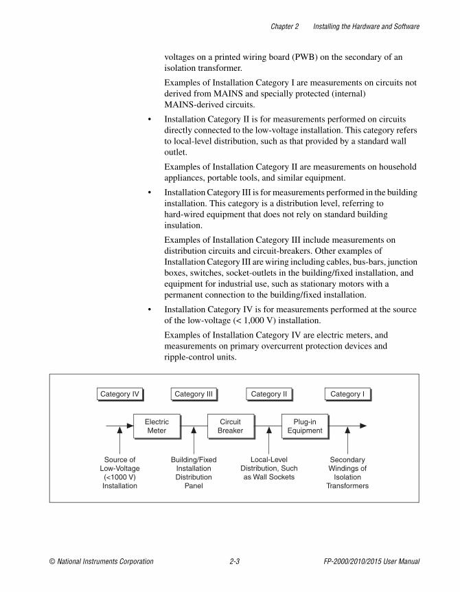
Operate FieldPoint products at or below Installation Category II.The following is a description of installation categories:
• Installation Category I is for measurements performed on circuits notdirectly connected to MAINS1. This category is a signal level such as
1 MAINS is defined as the electricity supply system to which the equipment concerned is designed to be connected for eitherpowering the equipment or for measurement purposes.
Chapter 2 Installing the Hardware and Software
© National Instruments Corporation 2-3 FP-2000/2010/2015 User Manual
voltages on a printed wiring board (PWB) on the secondary of anisolation transformer.
Examples of Installation Category I are measurements on circuits notderived from MAINS and specially protected (internal)MAINS-derived circuits.
• Installation Category II is for measurements performed on circuitsdirectly connected to the low-voltage installation. This category refersto local-level distribution, such as that provided by a standard walloutlet.
Examples of Installation Category II are measurements on householdappliances, portable tools, and similar equipment.
• Installation Category III is for measurements performed in the buildinginstallation. This category is a distribution level, referring tohard-wired equipment that does not rely on standard buildinginsulation.
Examples of Installation Category III include measurements ondistribution circuits and circuit-breakers. Other examples ofInstallation Category III are wiring including cables, bus-bars, junctionboxes, switches, socket-outlets in the building/fixed installation, andequipment for industrial use, such as stationary motors with apermanent connection to the building/fixed installation.
• Installation Category IV is for measurements performed at the sourceof the low-voltage (< 1,000 V) installation.
Examples of Installation Category IV are electric meters, andmeasurements on primary overcurrent protection devices andripple-control units.
Chapter 2 Installing the Hardware and Software
FP-2000/2010/2015 User Manual 2-4 ni.com
Mounting the FP-20xx and Terminal BasesYou can mount the FieldPoint system either to a DIN rail or directly ona panel. Panel mounting is generally the more secure option, but DIN railmounting might be more convenient for your application. The followingsections give instructions for both mounting methods.
Mounting the FP-20xx on a DIN RailThe FP-20xx network module has a simple rail clip for reliable mountingonto a standard 35 mm DIN rail. Follow these steps if you choose to mountthe module on a DIN rail:
1. Write down the serial number from the back of the FP-20xx before youmount it.
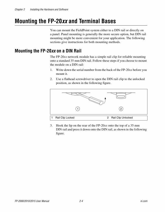
2. Use a flathead screwdriver to open the DIN rail clip to the unlockedposition, as shown in the following figure.
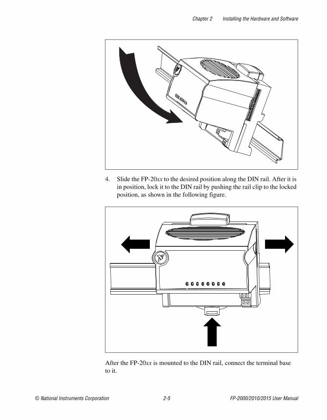
3. Hook the lip on the rear of the FP-20xx onto the top of a 35 mmDIN rail and press it down onto the DIN rail, as shown in the followingfigure.
1 Rail Clip Locked 2 Rail Clip Unlocked
1 2
Chapter 2 Installing the Hardware and Software
© National Instruments Corporation 2-5 FP-2000/2010/2015 User Manual
4. Slide the FP-20xx to the desired position along the DIN rail. After it isin position, lock it to the DIN rail by pushing the rail clip to the lockedposition, as shown in the following figure.
After the FP-20xx is mounted to the DIN rail, connect the terminal baseto it.
Chapter 2 Installing the Hardware and Software
FP-2000/2010/2015 User Manual 2-6 ni.com
Connecting Terminal Bases with DIN Rail MountingFollow these steps to connect a terminal base to an FP-20xx networkmodule using DIN rail mounting.
Caution To avoid damaging the FP-20xx and the terminal bases, make sure that poweris not applied to it while you install or remove terminal bases.
1. Mount the terminal base onto the DIN rail in the same way youinstalled the network module.
2. Attach the terminal base to the FP-20xx by firmly mating the localbus connectors. Be careful not to bend any pins.
3. To add more terminal bases, install them on the rail and connect theirlocal bus connectors together. In most cases a single FP-20xxcan support up to nine terminal bases, depending on the powerconsumption of the I/O modules. Refer to the Wiring Power to theFieldPoint System section for more information about powerrequirements.
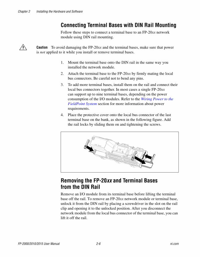
4. Place the protective cover onto the local bus connector of the lastterminal base on the bank, as shown in the following figure. Addthe rail locks by sliding them on and tightening the screws.
Removing the FP-20xx and Terminal Basesfrom the DIN RailRemove an I/O module from its terminal base before lifting the terminalbase off the rail. To remove an FP-20xx network module or terminal base,unlock it from the DIN rail by placing a screwdriver in the slot on the railclip and opening it to the unlocked position. After you disconnect thenetwork module from the local bus connector of the terminal base, you canlift it off the rail.
Chapter 2 Installing the Hardware and Software
© National Instruments Corporation 2-7 FP-2000/2010/2015 User Manual
Mounting the FP-20xx to a PanelFollow these steps if you choose to install the optional FieldPoint networkpanel-mount accessory and mount the FP-20xx network module to a panel.You can order the panel-mount accessory, part number 777609-01, fromNational Instruments.
1. Write down the serial number from the back of the FP-20xx before youmount it.
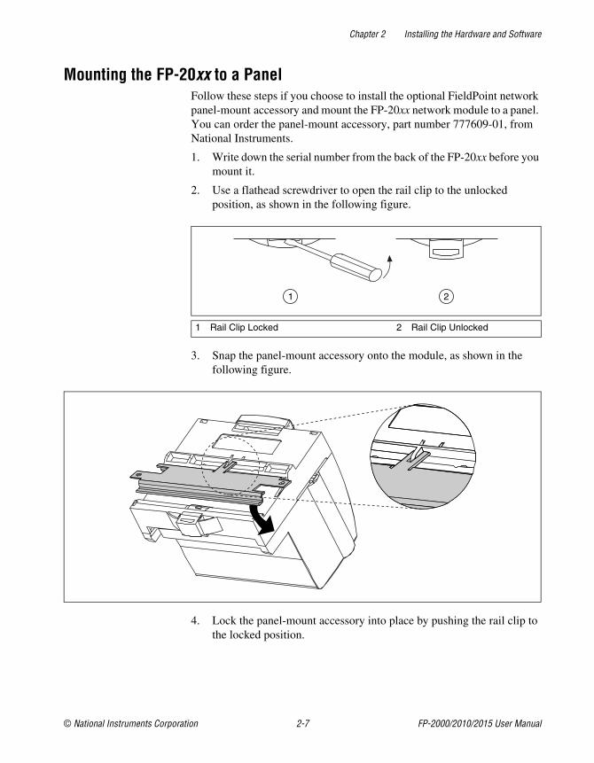
2. Use a flathead screwdriver to open the rail clip to the unlockedposition, as shown in the following figure.
3. Snap the panel-mount accessory onto the module, as shown in thefollowing figure.
4. Lock the panel-mount accessory into place by pushing the rail clip tothe locked position.
1 Rail Clip Locked 2 Rail Clip Unlocked
1 2
Chapter 2 Installing the Hardware and Software
FP-2000/2010/2015 User Manual 2-8 ni.com
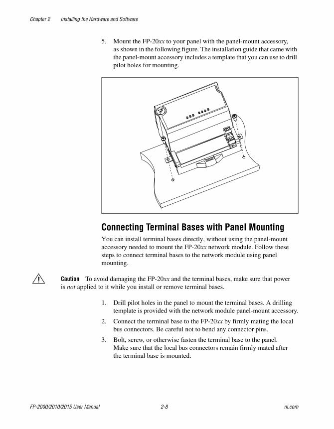
5. Mount the FP-20xx to your panel with the panel-mount accessory,as shown in the following figure. The installation guide that came withthe panel-mount accessory includes a template that you can use to drillpilot holes for mounting.
Connecting Terminal Bases with Panel MountingYou can install terminal bases directly, without using the panel-mountaccessory needed to mount the FP-20xx network module. Follow thesesteps to connect terminal bases to the network module using panelmounting.
Caution To avoid damaging the FP-20xx and the terminal bases, make sure that poweris not applied to it while you install or remove terminal bases.
1. Drill pilot holes in the panel to mount the terminal bases. A drillingtemplate is provided with the network module panel-mount accessory.
2. Connect the terminal base to the FP-20xx by firmly mating the localbus connectors. Be careful not to bend any connector pins.
3. Bolt, screw, or otherwise fasten the terminal base to the panel.Make sure that the local bus connectors remain firmly mated afterthe terminal base is mounted.
Chapter 2 Installing the Hardware and Software
© National Instruments Corporation 2-9 FP-2000/2010/2015 User Manual
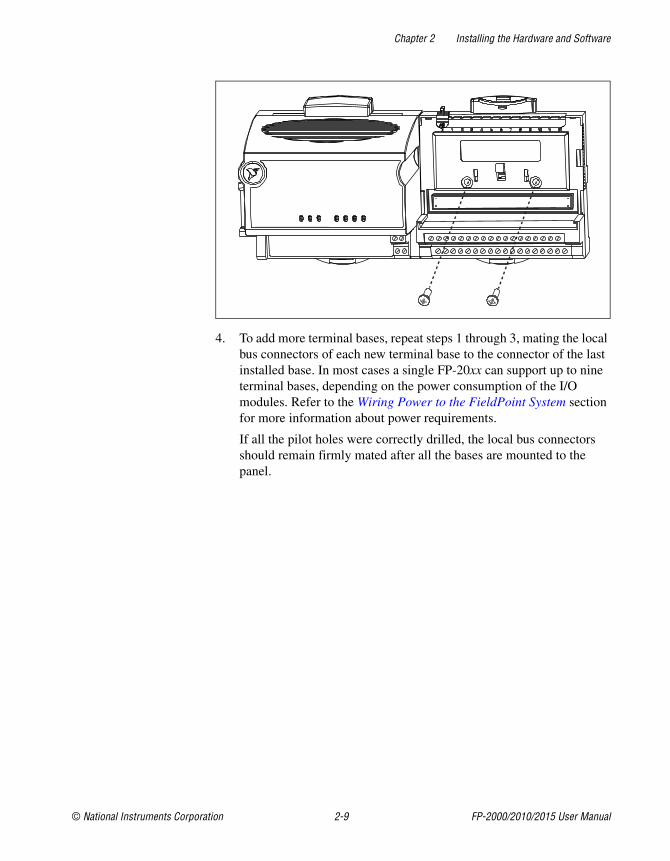
4. To add more terminal bases, repeat steps 1 through 3, mating the localbus connectors of each new terminal base to the connector of the lastinstalled base. In most cases a single FP-20xx can support up to nineterminal bases, depending on the power consumption of the I/Omodules. Refer to the Wiring Power to the FieldPoint System sectionfor more information about power requirements.
If all the pilot holes were correctly drilled, the local bus connectorsshould remain firmly mated after all the bases are mounted to thepanel.
Chapter 2 Installing the Hardware and Software
FP-2000/2010/2015 User Manual 2-10 ni.com
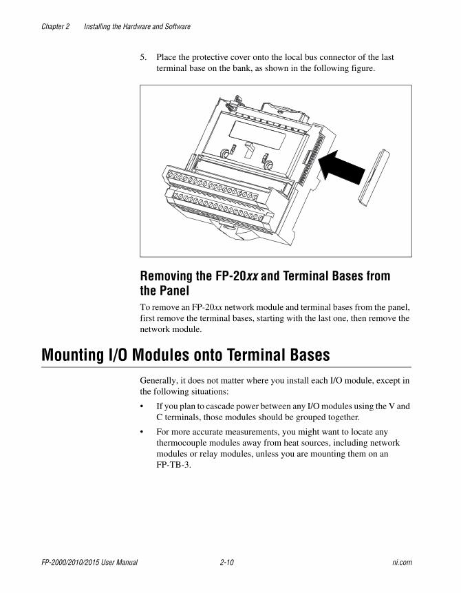
5. Place the protective cover onto the local bus connector of the lastterminal base on the bank, as shown in the following figure.
Removing the FP-20xx and Terminal Bases fromthe PanelTo remove an FP-20xx network module and terminal bases from the panel,first remove the terminal bases, starting with the last one, then remove thenetwork module.
Mounting I/O Modules onto Terminal BasesGenerally, it does not matter where you install each I/O module, except inthe following situations:
• If you plan to cascade power between any I/O modules using the V andC terminals, those modules should be grouped together.
• For more accurate measurements, you might want to locate anythermocouple modules away from heat sources, including networkmodules or relay modules, unless you are mounting them on anFP-TB-3.
Chapter 2 Installing the Hardware and Software
© National Instruments Corporation 2-11 FP-2000/2010/2015 User Manual
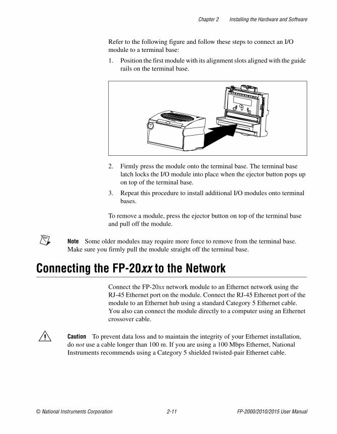
Refer to the following figure and follow these steps to connect an I/Omodule to a terminal base:
1. Position the first module with its alignment slots aligned with the guiderails on the terminal base.
2. Firmly press the module onto the terminal base. The terminal baselatch locks the I/O module into place when the ejector button pops upon top of the terminal base.
3. Repeat this procedure to install additional I/O modules onto terminalbases.
To remove a module, press the ejector button on top of the terminal baseand pull off the module.
Note Some older modules may require more force to remove from the terminal base.Make sure you firmly pull the module straight off the terminal base.
Connecting the FP-20xx to the NetworkConnect the FP-20xx network module to an Ethernet network using theRJ-45 Ethernet port on the module. Connect the RJ-45 Ethernet port of themodule to an Ethernet hub using a standard Category 5 Ethernet cable.You also can connect the module directly to a computer using an Ethernetcrossover cable.
Caution To prevent data loss and to maintain the integrity of your Ethernet installation,do not use a cable longer than 100 m. If you are using a 100 Mbps Ethernet, NationalInstruments recommends using a Category 5 shielded twisted-pair Ethernet cable.
Chapter 2 Installing the Hardware and Software
FP-2000/2010/2015 User Manual 2-12 ni.com
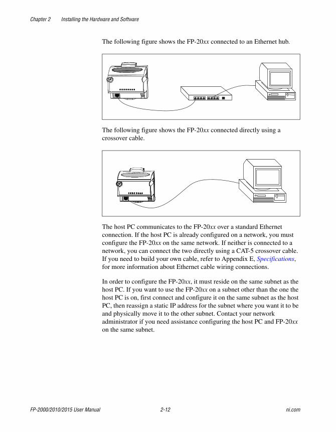
The following figure shows the FP-20xx connected to an Ethernet hub.
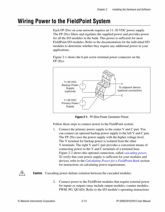
The following figure shows the FP-20xx connected directly using acrossover cable.
The host PC communicates to the FP-20xx over a standard Ethernetconnection. If the host PC is already configured on a network, you mustconfigure the FP-20xx on the same network. If neither is connected to anetwork, you can connect the two directly using a CAT-5 crossover cable.If you need to build your own cable, refer to Appendix E, Specifications,for more information about Ethernet cable wiring connections.
In order to configure the FP-20xx, it must reside on the same subnet as thehost PC. If you want to use the FP-20xx on a subnet other than the one thehost PC is on, first connect and configure it on the same subnet as the hostPC, then reassign a static IP address for the subnet where you want it to beand physically move it to the other subnet. Contact your networkadministrator if you need assistance configuring the host PC and FP-20xxon the same subnet.
Chapter 2 Installing the Hardware and Software
© National Instruments Corporation 2-13 FP-2000/2010/2015 User Manual
Wiring Power to the FieldPoint SystemEach FP-20xx on your network requires an 11–30 VDC power supply.The FP-20xx filters and regulates the supplied power and provides powerfor all the I/O modules in the bank. This power is sufficient for mostFieldPoint I/O modules. Refer to the documentation for the individual I/Omodules to determine whether they require any additional power in yourapplications.
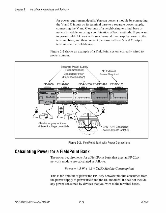
Figure 2-1 shows the 6-pin screw-terminal power connector on theFP-20xx.
Figure 2-1. FP-20xx Power Connector Pinout
Follow these steps to connect power to the FieldPoint system:
1. Connect the primary power supply to the center V and C pair. Youcan connect an optional backup power supply to the left V and C pair.The FP-20xx uses the power supply with the higher voltage level.The V terminal for backup power is isolated from the otherV terminals. The right V and C pair provides a convenient means ofconnecting power to the V and C terminals of a terminal base.Figure 2-2 shows this optional connection, called cascading power.To verify that your power supply is sufficient for your modules anddevices, refer to the Calculating Power for a FieldPoint Bank sectionfor instructions on calculating power requirements.
Caution Cascading power defeats isolation between the cascaded modules.
2. Connect power to the FieldPoint modules that require external powerfor inputs or outputs (may include output modules, counter modules,PWM, PG, QUAD). Refer to the I/O module’s operating instructions
v v v
c c c
11-30 VDCBackup Power
Supply(optional)
+–
+–
11-30 VDCPrimary Power
Supply
V
C
To adjacent device(optional connection)
Chapter 2 Installing the Hardware and Software
FP-2000/2010/2015 User Manual 2-14 ni.com
for power requirement details. You can power a module by connectingthe V and C inputs on its terminal base to a separate power supply,connecting the V and C outputs of a neighboring terminal base ornetwork module, or using a combination of both methods. If you wantto power field I/O devices from a terminal base, supply power to theterminal base, and then connect the terminal base V and C outputterminals to the field device.
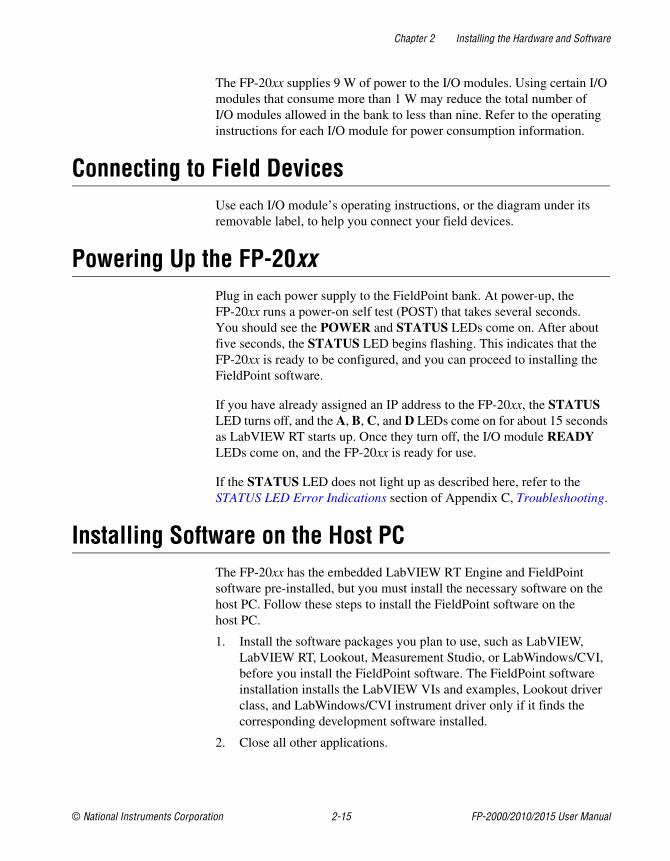
Figure 2-2 shows an example of a FieldPoint system correctly wired topower sources.
Figure 2-2. FieldPoint Bank with Power Connections
Calculating Power for a FieldPoint BankThe power requirements for a FieldPoint bank that uses an FP-20xxnetwork module are calculated as follows:
Power = 4.5 W + 1.1 * ∑(I/O Module Consumption)
This is the amount of power the FP-20xx network module consumes fromthe power supply to power itself and the I/O modules. It does not includeany power consumed by devices that you wire to the terminal bases.
15 16 V
31 32 C
V 1 32
C 17 18CAUTION: Cascadingpower defeats isolation.
Shades of gray indicatedifferent voltage potentials.
FP-TC-120FP-RLY-420FP-AO-200FP-AI-100FP-2000
Separate Power Supply(Recommended)
Cascaded Power(Reduces Isolation)
No ExternalPower Required
Chapter 2 Installing the Hardware and Software
© National Instruments Corporation 2-15 FP-2000/2010/2015 User Manual
The FP-20xx supplies 9 W of power to the I/O modules. Using certain I/Omodules that consume more than 1 W may reduce the total number ofI/O modules allowed in the bank to less than nine. Refer to the operatinginstructions for each I/O module for power consumption information.
Connecting to Field DevicesUse each I/O module’s operating instructions, or the diagram under itsremovable label, to help you connect your field devices.
Powering Up the FP-20xxPlug in each power supply to the FieldPoint bank. At power-up, theFP-20xx runs a power-on self test (POST) that takes several seconds.You should see the POWER and STATUS LEDs come on. After aboutfive seconds, the STATUS LED begins flashing. This indicates that theFP-20xx is ready to be configured, and you can proceed to installing theFieldPoint software.
If you have already assigned an IP address to the FP-20xx, the STATUSLED turns off, and the A, B, C, and D LEDs come on for about 15 secondsas LabVIEW RT starts up. Once they turn off, the I/O module READYLEDs come on, and the FP-20xx is ready for use.
If the STATUS LED does not light up as described here, refer to theSTATUS LED Error Indications section of Appendix C, Troubleshooting.
Installing Software on the Host PCThe FP-20xx has the embedded LabVIEW RT Engine and FieldPointsoftware pre-installed, but you must install the necessary software on thehost PC. Follow these steps to install the FieldPoint software on thehost PC.
1. Install the software packages you plan to use, such as LabVIEW,LabVIEW RT, Lookout, Measurement Studio, or LabWindows/CVI,before you install the FieldPoint software. The FieldPoint softwareinstallation installs the LabVIEW VIs and examples, Lookout driverclass, and LabWindows/CVI instrument driver only if it finds thecorresponding development software installed.
2. Close all other applications.
Chapter 2 Installing the Hardware and Software
FP-2000/2010/2015 User Manual 2-16 ni.com
3. Insert the FieldPoint software CD into the CD-ROM drive on yourcomputer.
4. Follow the onscreen instructions to complete the installation.
Note If the setup does not launch automatically, select Start»Run from Windows,enter d:\setup, where d is the letter of your CD-ROM drive, and select OK.
The hardware and software installation is now complete. Proceed toChapter 3, Hardware and Software Configuration.
© National Instruments Corporation 3-1 FP-2000/2010/2015 User Manual
3Hardware and SoftwareConfiguration
This chapter describes the details of configuring FieldPoint hardware andsoftware, verifying the configuration, and accessing the channels on theFP-20xx from other software running on the host PC.
Configuring the FP-20xx in FieldPoint ExplorerTo get started with FieldPoint Explorer, follow these steps:
1. Make sure that LabVIEW RT and the FieldPoint hardware andsoftware have been installed as explained in Chapter 2, Installing theHardware and Software, and in the LabVIEW RT manual. Verify thatthe FieldPoint system is powered on.
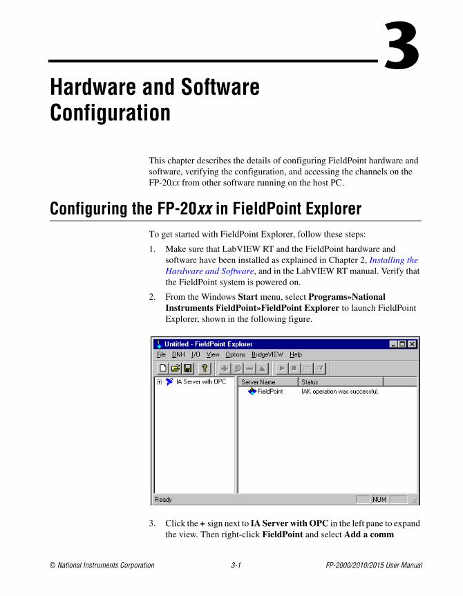
2. From the Windows Start menu, select Programs»NationalInstruments FieldPoint»FieldPoint Explorer to launch FieldPointExplorer, shown in the following figure.
3. Click the + sign next to IA Server with OPC in the left pane to expandthe view. Then right-click FieldPoint and select Add a comm
Chapter 3 Hardware and Software Configuration
FP-2000/2010/2015 User Manual 3-2 ni.com
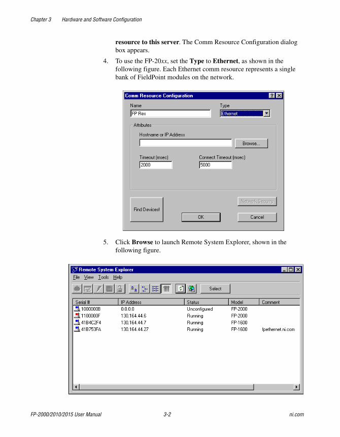
resource to this server. The Comm Resource Configuration dialogbox appears.
4. To use the FP-20xx, set the Type to Ethernet, as shown in thefollowing figure. Each Ethernet comm resource represents a singlebank of FieldPoint modules on the network.
5. Click Browse to launch Remote System Explorer, shown in thefollowing figure.
Chapter 3 Hardware and Software Configuration
© National Instruments Corporation 3-3 FP-2000/2010/2015 User Manual
Remote System Explorer searches for any FP-20xx or other NationalInstruments Ethernet devices on the subnet. The serial number showncorresponds to the serial number of your FP-20xx. The status of themodule is Unconfigured because you have not set an IP addressfor it.
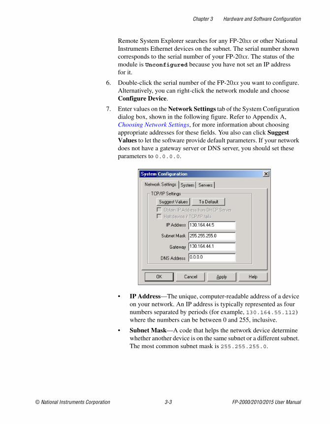
6. Double-click the serial number of the FP-20xx you want to configure.Alternatively, you can right-click the network module and chooseConfigure Device.
7. Enter values on the Network Settings tab of the System Configurationdialog box, shown in the following figure. Refer to Appendix A,Choosing Network Settings, for more information about choosingappropriate addresses for these fields. You also can click SuggestValues to let the software provide default parameters. If your networkdoes not have a gateway server or DNS server, you should set theseparameters to 0.0.0.0.
• IP Address—The unique, computer-readable address of a deviceon your network. An IP address is typically represented as fournumbers separated by periods (for example, 130.164.55.112)where the numbers can be between 0 and 255, inclusive.
• Subnet Mask—A code that helps the network device determinewhether another device is on the same subnet or a different subnet.The most common subnet mask is 255.255.255.0.
Chapter 3 Hardware and Software Configuration
FP-2000/2010/2015 User Manual 3-4 ni.com
• Gateway—The IP address of a device that acts as a gatewayserver, which is a connection between two networks.
• DNS Address—The IP address of a network device that storeshost names and translates them into IP addresses.
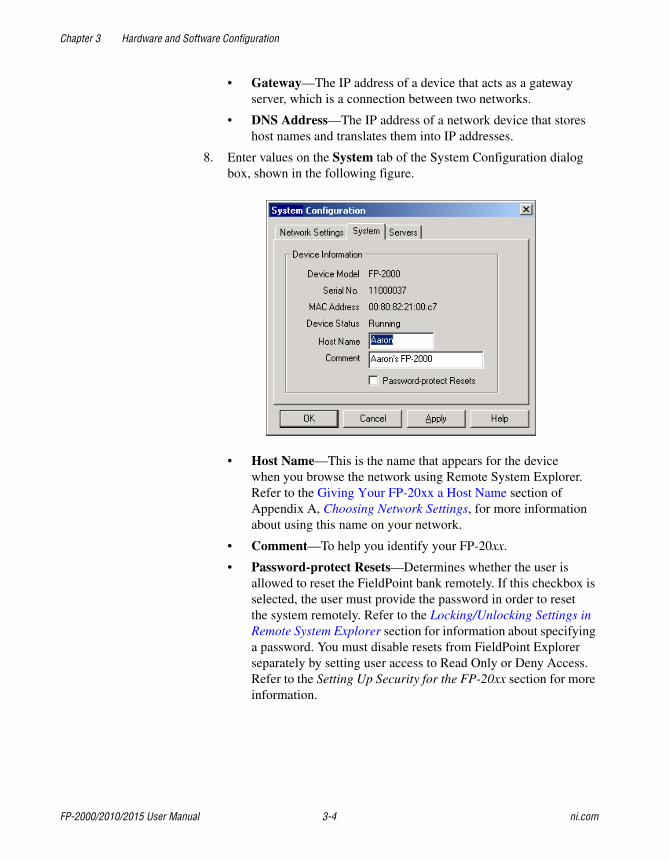
8. Enter values on the System tab of the System Configuration dialogbox, shown in the following figure.
• Host Name—This is the name that appears for the devicewhen you browse the network using Remote System Explorer.Refer to the Giving Your FP-20xx a Host Name section ofAppendix A, Choosing Network Settings, for more informationabout using this name on your network.
• Comment—To help you identify your FP-20xx.
• Password-protect Resets—Determines whether the user isallowed to reset the FieldPoint bank remotely. If this checkbox isselected, the user must provide the password in order to resetthe system remotely. Refer to the Locking/Unlocking Settings inRemote System Explorer section for information about specifyinga password. You must disable resets from FieldPoint Explorerseparately by setting user access to Read Only or Deny Access.Refer to the Setting Up Security for the FP-20xx section for moreinformation.
Chapter 3 Hardware and Software Configuration
© National Instruments Corporation 3-5 FP-2000/2010/2015 User Manual
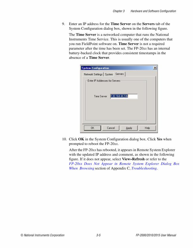
9. Enter an IP address for the Time Server on the Servers tab of theSystem Configuration dialog box, shown in the following figure.
The Time Server is a networked computer that runs the NationalInstruments Time Service. This is usually one of the computers thatyou run FieldPoint software on. Time Server is not a requiredparameter after the time has been set. The FP-20xx has an internalbattery-backed clock that provides consistent timestamps in theabsence of a Time Server.
10. Click OK in the System Configuration dialog box. Click Yes whenprompted to reboot the FP-20xx.
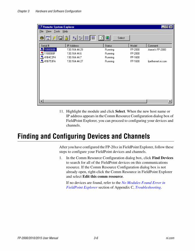
After the FP-20xx has rebooted, it appears in Remote System Explorerwith the updated IP address and comment, as shown in the followingfigure. If it does not appear, select View»Refresh or refer to theFP-20xx Does Not Appear in Remote System Explorer Dialog BoxWhen Browsing section of Appendix C, Troubleshooting.
Chapter 3 Hardware and Software Configuration
FP-2000/2010/2015 User Manual 3-6 ni.com
11. Highlight the module and click Select. When the new host name orIP address appears in the Comm Resource Configuration dialog box ofFieldPoint Explorer, you can proceed to configuring your devices andchannels.
Finding and Configuring Devices and ChannelsAfter you have configured the FP-20xx in FieldPoint Explorer, follow thesesteps to configure your FieldPoint devices and channels.
1. In the Comm Resource Configuration dialog box, click Find Devicesto search for all of the FieldPoint devices on this communicationsresource. If the Comm Resource Configuration dialog box is notalready open, right-click the Comm Resource in FieldPoint Explorerand select Edit this comm resource.
If no devices are found, refer to the No Modules Found Error inFieldPoint Explorer section of Appendix C, Troubleshooting.
Chapter 3 Hardware and Software Configuration
© National Instruments Corporation 3-7 FP-2000/2010/2015 User Manual
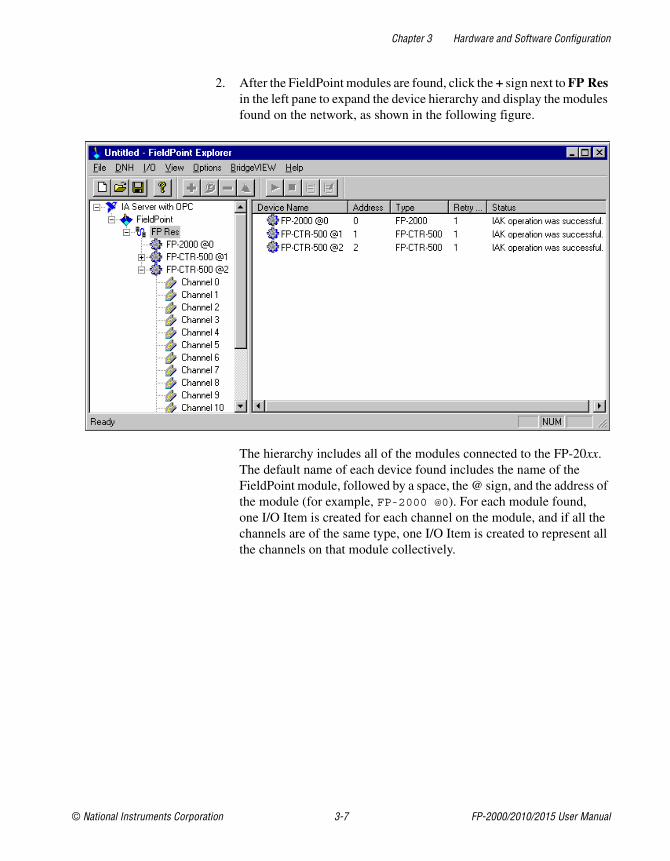
2. After the FieldPoint modules are found, click the + sign next to FP Resin the left pane to expand the device hierarchy and display the modulesfound on the network, as shown in the following figure.
The hierarchy includes all of the modules connected to the FP-20xx.The default name of each device found includes the name of theFieldPoint module, followed by a space, the @ sign, and the address ofthe module (for example, FP-2000 @0). For each module found,one I/O Item is created for each channel on the module, and if all thechannels are of the same type, one I/O Item is created to represent allthe channels on that module collectively.
Chapter 3 Hardware and Software Configuration
FP-2000/2010/2015 User Manual 3-8 ni.com
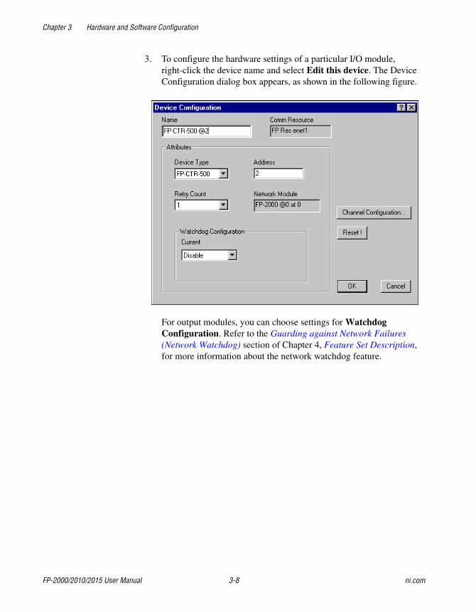
3. To configure the hardware settings of a particular I/O module,right-click the device name and select Edit this device. The DeviceConfiguration dialog box appears, as shown in the following figure.
For output modules, you can choose settings for WatchdogConfiguration. Refer to the Guarding against Network Failures(Network Watchdog) section of Chapter 4, Feature Set Description,for more information about the network watchdog feature.
Chapter 3 Hardware and Software Configuration
© National Instruments Corporation 3-9 FP-2000/2010/2015 User Manual
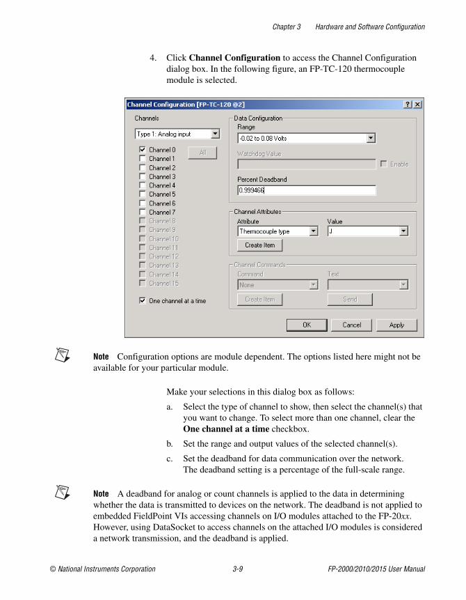
4. Click Channel Configuration to access the Channel Configurationdialog box. In the following figure, an FP-TC-120 thermocouplemodule is selected.
Note Configuration options are module dependent. The options listed here might not beavailable for your particular module.
Make your selections in this dialog box as follows:
a. Select the type of channel to show, then select the channel(s) thatyou want to change. To select more than one channel, clear theOne channel at a time checkbox.
b. Set the range and output values of the selected channel(s).
c. Set the deadband for data communication over the network.The deadband setting is a percentage of the full-scale range.
Note A deadband for analog or count channels is applied to the data in determiningwhether the data is transmitted to devices on the network. The deadband is not applied toembedded FieldPoint VIs accessing channels on I/O modules attached to the FP-20xx.However, using DataSocket to access channels on the attached I/O modules is considereda network transmission, and the deadband is applied.
Chapter 3 Hardware and Software Configuration
FP-2000/2010/2015 User Manual 3-10 ni.com
d. Set attributes for selected channel(s) by selecting the attribute andentering the desired value.
e. Send commands to the selected channel(s) by choosing acommand and value and clicking Send.
f. Repeat this procedure for each channel you want to configure.
g. Click OK, or click Apply to save the changes and continue toconfigure channels. When you click OK or Apply, the changesare immediately sent to the device and saved in its nonvolatilememory.
Saving Hardware Configuration as Power-Up StateWhen you are satisfied with the hardware configuration of your FieldPointsystem, you can save this configuration as the new power-up state for thebank.
1. Right-click the FP-20xx network module in the left pane of FieldPointExplorer, and select Edit this device.
2. Clear the factory configuration checkbox.
3. Specify the power-up settings with either of the following options:
• If you want only the range and attribute settings you configured inthe Finding and Configuring Devices and Channels section to besaved as power-up states, click OK. These settings are written tothe nonvolatile memory of the network module.
• If you want to save power-up values for the range and attributesettings and also all the current output states of the outputchannels, click Snapshot. This stores the current ranges,attributes, and output values of the bank to the nonvolatilememory of the network module. Click OK when you are finished.
Caution Using the Snapshot feature overwrites any power-up values you may havespecified for individual channels in the Channel Configuration dialog box.
Refer to the Storing a Custom Power-Up Configuration section ofChapter 4, Feature Set Description, for more information aboutconfiguring and changing the power-up values. Refer to the Guardingagainst Network Failures (Network Watchdog) section of Chapter 4,Feature Set Description, for information about configuring a networkwatchdog to guard against network failures.
Chapter 3 Hardware and Software Configuration
© National Instruments Corporation 3-11 FP-2000/2010/2015 User Manual
Using Other Features and Optionsin Remote System Explorer
You can access Remote System Explorer by right-clicking the CommResource in FieldPoint Explorer, selecting Edit this comm resource,then clicking Browse. You can use the Remote System Explorer toolbarbuttons, Tools menu, or right-click menu to access the following features:
• Configure Device—Use to configure the IP address, comment,and other parameters for the selected FP-20xx.
• Install/Upgrade Software—Use to install or upgrade LabVIEW RTsoftware on the selected FP-20xx.
• Reboot Device—Use to reboot the selected FP-20xx.
• View Installed Software—Use to view the LabVIEW RT and driversoftware versions installed on the selected FP-20xx.
• Lock/Unlock Device—Use to lock or unlock the system configurationwith a password.
• Device Location—Use to change the search location for FP-20xxmodules to the local subnet or to a specified IP address.
• View Error Log—Use to obtain detailed error information if you needto contact National Instruments technical support.
You can use the Remote System Explorer toolbar buttons or View menu toaccess the following features:
• Large icon view—Changes the view in the main window to largeicons.
• Small icon view—Changes the view in the main window to smallicons.
• List view—Changes the view in the main window to a list.
• Detailed view—Changes the view in the main window to a list withadditional information such as serial number, IP address, status,model, and comment.
• Refresh Browse List—Refreshes the list of FP-20xx modules andother National Instruments Ethernet devices found on the local subnetor at the specified IP address. Changes to IP address, comment, and soon do not appear in Remote System Explorer until you reboot theselected system and click Refresh Browse List.
Chapter 3 Hardware and Software Configuration
FP-2000/2010/2015 User Manual 3-12 ni.com
Setting Up Security for the FP-20xxYou can set network security options to limit host access, and you can lockthe settings made in Remote System Explorer.
Configuring Network SecurityYou can limit host access to the FP-20xx by setting access permissions fordifferent host machines. The default setting allows Read/Write access to allhost machines. To change the network security settings, follow these steps.
1. Right-click the comm resource in FieldPoint Explorer and select Editthis comm resource. The Comm Resource Configuration dialog boxappears with the Network Security button enabled.
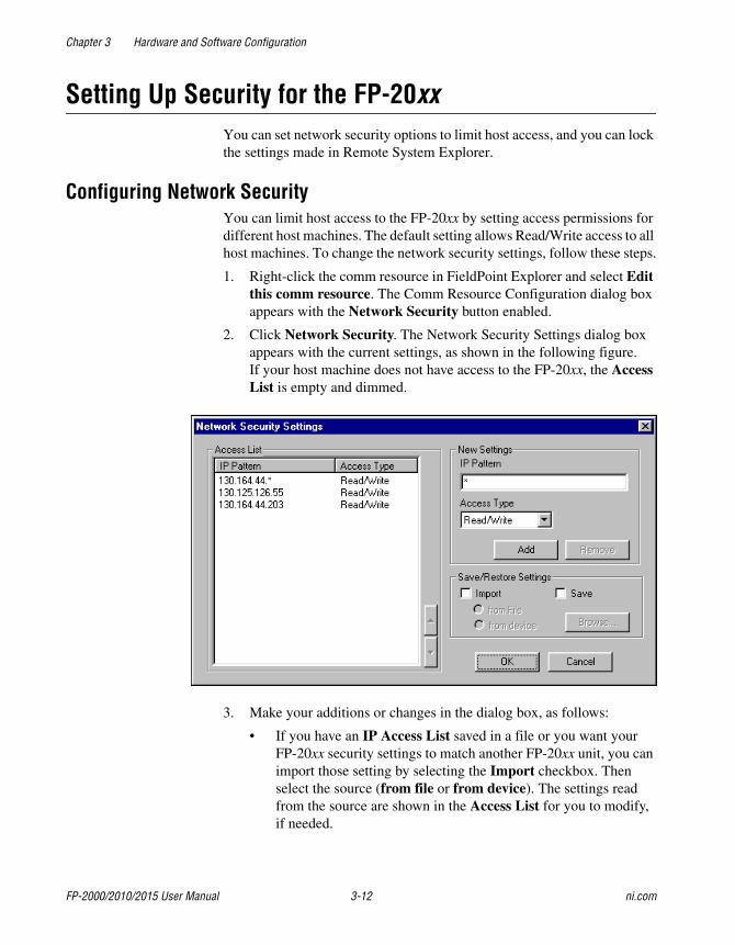
2. Click Network Security. The Network Security Settings dialog boxappears with the current settings, as shown in the following figure.If your host machine does not have access to the FP-20xx, the AccessList is empty and dimmed.
3. Make your additions or changes in the dialog box, as follows:
• If you have an IP Access List saved in a file or you want yourFP-20xx security settings to match another FP-20xx unit, you canimport those setting by selecting the Import checkbox. Thenselect the source (from file or from device). The settings readfrom the source are shown in the Access List for you to modify,if needed.
Chapter 3 Hardware and Software Configuration
© National Instruments Corporation 3-13 FP-2000/2010/2015 User Manual
• To add a host machine to the list, enter its IP address in theIP Pattern edit box, select the desired access type (Read/Write,Read Only, or Deny Access) from the Access Type list, then clickAdd. You can use the * wildcard when specifying the IP address.For example, to give Read/Write access to all hosts, enter * in theIP Pattern edit box, or to deny access to all machines on the111.222.333 subnet, enter 111.222.333.* in the IP Patternedit box.
• To remove a host machine from the list, either click the entry ortype the entry in the IP Pattern edit box, then click Remove orpress the <Del> key.
Note Once you modify the list, any IP Address that does not have any matching entry isdenied access to the FP-20xx.
• To change the order of the entries in the list, select an entry andclick the up arrow or down arrow button that is located next to theAccess List. A new entry is always added to the end of the list.You can have multiple matching entries for a given IP address.In that case, the first entry that matches the IP address is used,starting from the bottom of the list.
• To save the IP Access List to a file to be used for other FP-20xxmodules, select the Save checkbox and enter a file name.
4. Once you are satisfied with the changes, click OK. A dialog boxappears, prompting you for the password. After you enter the passwordand click OK, your changes are applied to the FP-20xx.
Locking/Unlocking Settings in Remote System ExplorerAfter you configure the FP-20xx, you can lock the settings made in RemoteSystem Explorer with a password to prevent others on your network fromchanging the configuration. In addition, a host PC on the network cannottarget LabVIEW RT to the FP-20xx without a password unless the host isin the RT Target: Access list.
Complete the following steps to lock or unlock the settings made in RemoteSystem Explorer:
1. Right-click the Comm Resource in FieldPoint Explorer, choose Editthis comm resource, and click Browse to launch Remote SystemExplorer.
2. Click the network module, then select Tools»Lock/Unlock Device.A checkmark by this menu item indicates that the device is locked.
Chapter 3 Hardware and Software Configuration
FP-2000/2010/2015 User Manual 3-14 ni.com
3. In the Locking System Configuration dialog box, enter a password tolock or unlock the device.
4. Click OK.
If you need to unlock the device configuration and you do not know thepassword, you must reset the FP-20xx and reconfigure it. Refer toAppendix B, Resetting the FP-20xx, for more information about resettingthe FP-20xx.
Downloading Item Information to the FP-20xxEvery time you select File»Save in FieldPoint Explorer, the FieldPointsystem configuration is saved in a .iak file. This file is used to access theconfiguration information, such as channel name, from other hostapplications like LabVIEW or LabWindows/CVI. To provide the samefunctionality for LabVIEW RT applications running on an FP-20xx, theitem names pertaining to the network module bank are also downloaded tothe network module whenever you select File»Save, assuming the networkmodule is powered on and connected to the network.
Note To download the item names without saving the .iak file, right-click the CommResource and select Download Configuration. To disable a configuration downloadwhen you select File»Save, uncheck Options»Download Configuration On Save.
Verifying the ConfigurationYou can verify the installation and configuration by monitoring an I/Ochannel or writing to an output channel from FieldPoint Explorer.
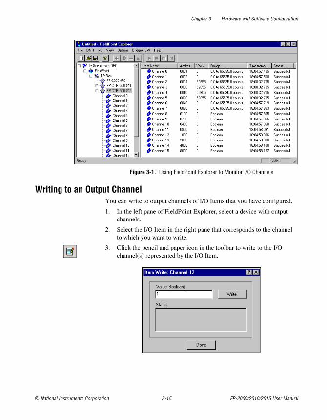
Monitoring an I/O ChannelYou can monitor FieldPoint devices that you have configured. In the leftpane of FieldPoint Explorer, select one of the devices, then click the greenarrow icon in the toolbar to start monitoring the items of that device.
The tag symbols of the items in the list view pane turn blue to show thatthey are being monitored. As shown in Figure 3-1, the Value column showsthe current value of the I/O channels defined by the I/O Items, and theStatus column shows any error conditions received while communicatingwith the FieldPoint network. Timestamp is the time when the FP-20xxmade the value available to the host PC.
Click the red square icon in the toolbar to stop monitoring the items.
Chapter 3 Hardware and Software Configuration
© National Instruments Corporation 3-15 FP-2000/2010/2015 User Manual
Figure 3-1. Using FieldPoint Explorer to Monitor I/O Channels
Writing to an Output ChannelYou can write to output channels of I/O Items that you have configured.
1. In the left pane of FieldPoint Explorer, select a device with outputchannels.
2. Select the I/O Item in the right pane that corresponds to the channelto which you want to write.
3. Click the pencil and paper icon in the toolbar to write to the I/Ochannel(s) represented by the I/O Item.
Chapter 3 Hardware and Software Configuration
FP-2000/2010/2015 User Manual 3-16 ni.com
4. Enter the value you want to write in the Value field and click Write towrite the value out. The value must be in the range of the channel thatyou configured in the Finding and Configuring Devices and Channelssection. For example, if the channel was configured for a range of0.0035 A to 0.021 A, and you want to write a value of 0.010 A(10 mA), enter 0.010 in the Value field. For discrete I/O channelswith a Boolean range, enter 1 or 0 in the Value field.
Note If your PC is configured to use a comma as a decimal symbol, enter 0,010.
Using the FP-20xx from Host ApplicationsThe primary intended use for the FP-20xx is to run LabVIEW RT, but youcan use the module with other software on your host PC, even while youare using it to run LabVIEW RT. The following sections explain how toaccess the channels on the FP-20xx from software running on the host PC.
Lookout and the FP-20xxThe FP-20xx network module integrates easily with National InstrumentsLookout 4.0 and later. You can access the module the same way you wouldaccess another desktop computer running Lookout. You can access thechannel data, ranges, attributes, and commands from Lookout, as well asseveral control variables, such as Reset and Snapshot.
To access the FP-20xx with Lookout 3.8 or earlier, use the FieldPoint OPCserver. You cannot use the FieldPoint 3.8 Lookout driver class with theFP-20xx.
To use the FP-20xx with Lookout 4.0 or later, follow these steps:
1. Configure the FP-20xx in FieldPoint Explorer as describeConfiguring the FP-20xx in FieldPoint Explorer section.
d in the
2. Start Lookout, and create a new process or open an existing one.
3. Register the FP-20xx as a networked computer in Lookout. SelectObject»Object Explorer or Object»Connection Browser from themenu bar and right-click Network. Choose Register networkcomputer from the pop-up menu. Type the IP Address or host name ofthe FP-20xx in the Computer name field and click OK.
4. When you create a Lookout object or expression, you can connect it todata on the FP-20xx network module. In the Insert Expression dialogbox, click Network to browse the registered computers and FP-20xx
Chapter 3 Hardware and Software Configuration
© National Instruments Corporation 3-17 FP-2000/2010/2015 User Manual
modules. Click the IP address or host name of the network module andbrowse to the desired data.
An alternative method is to use the fpoint.cbx to access the channeldata.
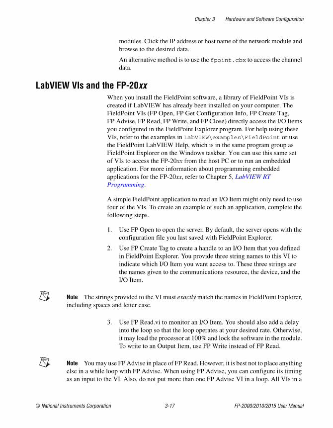
LabVIEW VIs and the FP-20xxWhen you install the FieldPoint software, a library of FieldPoint VIs iscreated if LabVIEW has already been installed on your computer. TheFieldPoint VIs (FP Open, FP Get Configuration Info, FP Create Tag,FP Advise, FP Read, FP Write, and FP Close) directly access the I/O Itemsyou configured in the FieldPoint Explorer program. For help using theseVIs, refer to the examples in LabVIEW\examples\FieldPoint or usethe FieldPoint LabVIEW Help, which is in the same program group asFieldPoint Explorer on the Windows taskbar. You can use this same setof VIs to access the FP-20xx from the host PC or to run an embeddedapplication. For more information about programming embeddedapplications for the FP-20xx, refer to Chapter 5, LabVIEW RTProgramming.
A simple FieldPoint application to read an I/O Item might only need to usefour of the VIs. To create an example of such an application, complete thefollowing steps.
1. Use FP Open to open the server. By default, the server opens with theconfiguration file you last saved with FieldPoint Explorer.
2. Use FP Create Tag to create a handle to an I/O Item that you definedin FieldPoint Explorer. You provide three string names to this VI toindicate which I/O Item you want access to. These three strings arethe names given to the communications resource, the device, and theI/O Item.
Note The strings provided to the VI must exactly match the names in FieldPoint Explorer,including spaces and letter case.
3. Use FP Read.vi to monitor an I/O Item. You should also add a delayinto the loop so that the loop operates at your desired rate. Otherwise,it may load the processor at 100% and lock the software in the module.To write to an Output Item, use FP Write instead of FP Read.
Note You may use FP Advise in place of FP Read. However, it is best not to place anythingelse in a while loop with FP Advise. When using FP Advise, you can configure its timingas an input to the VI. Also, do not put more than one FP Advise VI in a loop. All VIs in a
Chapter 3 Hardware and Software Configuration
FP-2000/2010/2015 User Manual 3-18 ni.com
loop execute only once each time a loop runs, and FP Advise VIs only complete at theiradvise rate. If you had more than one FP Advise VI in the loop, the loop (and therefore allof the FP Advise VIs in the loop) would only execute at the slowest rate of the Advises.The loop might not execute more than once if any of the Advises is set to complete“On Data Change” and the data of the corresponding I/O Item never changes.
4. Use FP Close to close the server. This action also stops all pendingadvise operations. Be sure to use only one FP Close.
5. The following figure gives an example of a LabVIEW diagram withFieldPoint items.
LabWindows/CVI Functions and the FP-20xxWhen you install the FieldPoint software, a LabWindows/CVI instrumentdriver for FieldPoint is installed if LabWindows/CVI has already beeninstalled on your computer. This instrument driver includes function panelsto call C functions that directly access the I/O Items you configured in theFieldPoint Explorer program. In addition, a set of sample projects is placedin your LabWindows/CVI Samples directory. Using these examples isthe best way to get familiar with these functions. The FieldPoint CVI Helpdocument is in the same program group on the Windows taskbar asFieldPoint Explorer. This help document describes each function in theinstrument driver with a description of the C syntax, a description of eachparameter, and a list of possible error codes.
Chapter 3 Hardware and Software Configuration
© National Instruments Corporation 3-19 FP-2000/2010/2015 User Manual
Note FieldPoint CVI Interface Compatibility Modes—The FieldPoint software shipswith object (.obj) files to support the different compiler compatibility modes thatLabWindows/CVI supports (Microsoft Visual C/C++, Borland, Watcom, and Symantec).When the FieldPoint software is installed, the .obj file corresponding to the configuredcompatibility mode is installed.
FieldPoint OPC Server and the FP-20xxThe FieldPoint OPC server conforms to the OPC Data Access 2.0 standard.OPC (OLE for Process Control) is an industry-standard device interfacespecification that provides interoperability between field devices such asFieldPoint and application software packages. The FieldPoint OPC server,like the other FieldPoint interfaces, imports the I/O Items that youconfigured in FieldPoint Explorer and makes them available as OPC Itemsto any OPC client. Therefore, if two computers are networked together, itis possible for an OPC client on one computer to access FieldPointhardware connected to the OPC server on another computer.
OPC clients differ in the features they offer and their presentation of theOPC interface. However, the basic steps involved are similar for most OPCclients.
Follow these steps to use the FieldPoint OPC server:
1. Launch your OPC client.
2. Open the FieldPoint OPC server, National Instruments.OPCFieldPoint, from the OPC client.
This server was registered with Windows when you installed theFieldPoint software. OPC clients should be able to show you a listof available registered servers, but you might have to type this namein yourself. The OPC client might automatically connect to the serverwhen you select it, but if you are given the option to explicitly connectto the FieldPoint OPC server, you should do so.
3. Create a group.
Groups are a collection of I/O Items. Some OPC clients might not giveyou the option of creating groups, or they might be created for you.
4. Select the I/O Items, which you configured in FieldPoint Explorer, thatyou want to read or write as a part of this group.
Many OPC clients can use the Browse Address Space feature ofthe FieldPoint OPC server to show you a list of all of the I/O Itemsyou configured in FieldPoint Explorer. However, if the OPC client youare using does not support this feature, you might need to type the ItemIDs of the I/O Items directly. The naming convention of the FieldPoint
Chapter 3 Hardware and Software Configuration
FP-2000/2010/2015 User Manual 3-20 ni.com
Item IDs is Comm resource name\Device Name\I/O Item namewhere the Comm resource name, Device name, and I/O Item name arethe names given in FieldPoint Explorer. For example, an Item IDassociated with one of the I/O Items might be the following:
FP Res\FP-TC-120 @1\Channel 0
In most cases, the preceding steps are all that is required to configure anOPC client to read from I/O Items of the FieldPoint OPC server. In somecases, the OPC client might require more information about the FieldPointOPC server. The following list contains additional information about theFieldPoint OPC server, which you may find helpful.
• The FieldPoint OPC server does not require an access path. Some OPCclients expect the access path to be included in the Item ID name ormight request the access path when you select I/O Items. You shouldbe able to leave the access path blank (empty string).
• The FieldPoint OPC interface is an out of process server.
• The FieldPoint OPC server supports both synchronous andasynchronous reads and writes.
• The FieldPoint OPC server uses the GetErrorString method to returnerror and diagnostic messages from the FieldPoint server andhardware. OPC clients that do not support this method might give youerror messages like “Bad, non-specific” along with an error code.Some OPC clients that do not support this GetErrorString method stillprovide a way for you to manually look up the FieldPoint messagecorresponding to the error code using this method.
Data CommunicationsThe FP-20xx network module provides several methods forcommunicating and sharing data with other FieldPoint systems, computers,and devices. The most common methods are to use DataSocket, serial VIs,TCP VIs, UDP VIs, or Data Publishing VIs, as described in the followingsections.
DataSocketDataSocket, a programming technology based on industry-standardTCP/IP, simplifies live data exchange between different applications onone computer or between computers connected via a network. DataSocketwas designed as an easy-to-use, high-performance programming interfacefor sharing and publishing live data in measurement and automationapplications. You can use DataSocket VIs to obtain data from other
Chapter 3 Hardware and Software Configuration
© National Instruments Corporation 3-21 FP-2000/2010/2015 User Manual
DataSocket servers, Lookout or LabVIEW DSC module applications,and data published by the Data Publishing VIs.
DataSocket uses uniform resource locators (URLs) to specify absolutepaths to data items. A URL consists of three separate components:protocol, network address, and locator. You are probably most familiar withURLs from using a Web browser. For example, http://www.ni.com/support/fieldpoint is a URL in which http is the protocol,www.ni.com is the network address, and support/fieldpoint isthe locator.
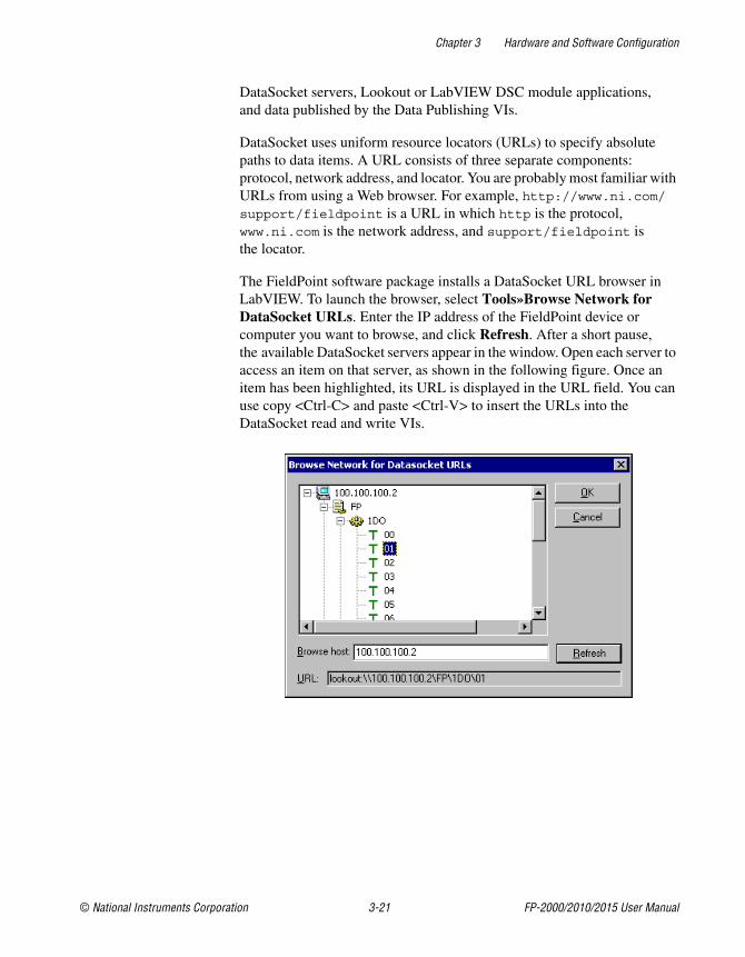
The FieldPoint software package installs a DataSocket URL browser inLabVIEW. To launch the browser, select Tools»Browse Network forDataSocket URLs. Enter the IP address of the FieldPoint device orcomputer you want to browse, and click Refresh. After a short pause,the available DataSocket servers appear in the window. Open each server toaccess an item on that server, as shown in the following figure. Once anitem has been highlighted, its URL is displayed in the URL field. You canuse copy <Ctrl-C> and paste <Ctrl-V> to insert the URLs into theDataSocket read and write VIs.
Chapter 3 Hardware and Software Configuration
FP-2000/2010/2015 User Manual 3-22 ni.com
DataSocket URLs for FieldPoint I/O ModulesThe following is an example of a DataSocket URL that points to a specificchannel of a FieldPoint I/O Module:
lookout:\\130.164.44.8\FP\1AI\01
In this URL, lookout is the protocol, 130.164.44.8 is the IP address ofthe FieldPoint Ethernet network module, and FP\1AI\01 is the locator.
The FieldPoint Process part of a URL provides the parent folder fromwhich you access all data items in a FieldPoint bank. The FieldPointProcess part of a URL has the following format:
\\[machine]\FP
where [machine] is the IP address or hostname of the FieldPoint Ethernetnetwork module.
The I/O Module Folder part of a URL provides the sub-folder from whichyou access all data items from a specific FieldPoint I/O module. The I/OModule Folder part of a URL has the following format:
\\[machine]\FP\[n]
where[n] consists of the numeric address and name of the I/O module. Theaddress of the I/O module is an integer from 1 to 9, where 1 represents theI/O module closest to the network module and 9 represents the I/O modulefarthest from the network module. The folder \\130.164.44.8\FP\1AIindicates the I/O module closest to the network module, and the AI meansthat it is an analog input module.
The Channel Data part of a URL provides the scaled data value of the inputor output value for a specific channel. The Channel Data part of a URL hasthe following format:
\\[machine]\FP\[n]\[channel]
where [channel] is a two-digit decimal number between 00 and 15.
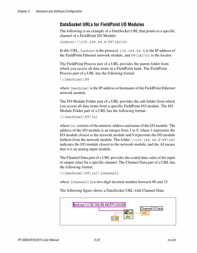
The following figure shows a DataSocket URL with Channel Data.
Chapter 3 Hardware and Software Configuration
© National Instruments Corporation 3-23 FP-2000/2010/2015 User Manual
The locator is read as channel 0 (00) of the analog input module in positionone (the first position to the right of the network module) on the bank.
Note If you are making only one connection to the FP-20xx, the Lookout protocolperforms better than OPC or DSTP (DataSocket Transfer Protocol).
Publish Data VIYou can use the Publish Data VI on the FieldPoint palette to create itemsand groups that are published using the National Instruments Ethernet(Lookout) protocol. A host computer or FP-20xx can link to these itemsusing DataSocket or using the native connection capabilities of Lookoutor the LabVIEW DSC module. The Publish Data VI creates data that otherVIs and applications can browse and read, write, or read/write from theFP-20xx. These items will also be accessible in FieldPoint Explorer and theFieldPoint OPC server.
Serial VIsYou can use the LabVIEW Serial VIs to communicate with other serialdevices through the RS-232 port on the FP-20xx. For example, you can usethe supplied FieldPoint Optomux library to communicate with an FP-1000connected to the FP-20xx. Refer to the FP-1000/1001 ProgrammerReference Manual for more information about the Optomux VIs.
Note The FP-20xx does not support VISA.
TCP and UDP VIsYou can use the LabVIEW TCP VIs to publish data from the FP-20xx tocomputers or devices on the network using TCP-based protocols. You canuse the LabVIEW UDP VIs to publish data from the FP-20xx to computerson the network using UDP (User Datagram Protocol).
Note The TCP and UDP VIs provide low-level access to your network. Use them onlywhen the supplied protocols do not fit into your application.
© National Instruments Corporation 4-1 FP-2000/2010/2015 User Manual
4Feature Set Description
This chapter describes the feature set for the FP-20xx network module.
Guarding against Network Failures (Network Watchdog)The network watchdog feature of the FP-20xx enables you to guard yoursystem against failures in the network connection, cables, or host computer.If the network watchdog is enabled and the FP-20xx loses communicationwith all hosts or clients over the network, the FP-20xx sets its outputchannels to predefined values (the watchdog state).
Note National Instruments recommends leaving the network watchdog disabled whenyou are running embedded applications on the FP-20xx.
Network watchdog output values can be different than power-up outputvalues. For example, you may want to turn on an output value when youpower up, but turn it off if network communication is lost.
The network watchdog for the bank is disabled by default. Follow thesesteps to enable it:
1. In FieldPoint Explorer, right-click an output module and selectEdit this device.
2. Select Enable or Enable on Use for the current watchdogconfiguration.
3. Click Channel Configuration, then configure these settings:
• Enable/disable the watchdog for each channel.
• Enter a watchdog data value for each channel.
4. Click OK.
Chapter 4 Feature Set Description
FP-2000/2010/2015 User Manual 4-2 ni.com
5. In the left pane of FieldPoint Explorer, right-click the FP-20xx, selectEdit this device, and configure these settings:
• Clear the factory configuration checkbox.
• Enable network watchdog for the bank.
• Enter a network watchdog timer value for the bank, a value thatspecifies the maximum allowable period of lost communicationwith hosts or clients over the network.
6. Click OK.
7. Select File»Save.
In addition to the network watchdog, the FP-20xx network modules supporta hardware watchdog that you can set up in LabVIEW RT. The VIs tocontrol the hardware watchdog are on the FieldPoint palette. Refer to theHardware Watchdog section of Chapter 5, LabVIEW RT Programming,or to the examples in labview\examples\rt\RT watchdog, for moreinformation about the hardware watchdog.
Storing a Custom Power-Up Configuration
Setting a Power-Up State with the Snapshot MethodThe Snapshot feature provides a single-step method for storing the currentstate of your FieldPoint hardware for use as the power-up state of the bank.
Caution Using the Snapshot feature overwrites any power-up values you have specifiedfor individual channels in the Channel Configuration dialog box.
1. Set the hardware to the state you want to use as a power-up state,including output values, ranges, and attributes.
2. Right-click the FP-20xx in the left pane of FieldPoint Explorer, andselect Edit this device.
3. Clear the factory configuration checkbox.
4. Click Snapshot. Click Yes and OK to approve the change.
5. Click OK in the Device Configuration dialog box.
6. Select File»Save.
To make incremental changes to the power-up values of individualchannels, use the procedure described in the Configurable Power-UpMethod section.
Chapter 4 Feature Set Description
© National Instruments Corporation 4-3 FP-2000/2010/2015 User Manual
Configurable Power-Up MethodWith the configurable power-up state feature, you can define the power-upconfiguration on a module-by-module basis. You do not need to set any ofthe channels to the desired power-up state, as you would with the Snapshotfeature. But you could use the configurable power-up method to adjustpreviously stored Snapshot information.
1. In FieldPoint Explorer, right-click an I/O module and select Edit thisdevice.
2. Click Channel Configuration, then enter range, attribute, and outputvalues for each channel.
3. Click OK twice.
4. Right-click the FP-20xx in the left pane of FieldPoint Explorer, andselect Edit this device.
5. Clear the factory configuration checkbox and click OK.
6. Select File»Save.
Inserting, Removing, and ReplacingI/O Modules (HotPnP)
The HotPnP feature simplifies system installation, configuration, andmaintenance. You can remove I/O modules and insert I/O modules intoempty terminal bases even while the system is engaged in network activity.You do not need to power down the bank or the system. In addition, you donot need to change the operation of the host computer or software in orderto use the HotPnP feature. I/O modules already working in the bank remainfully operational and accessible on the network.
When you insert an I/O module with the power on, it is automaticallyrecognized and made available on the network with the appropriateconfiguration. To see the new module in FieldPoint Explorer, click FindDevices in the Comm Resource Configuration dialog box, and selectFile»Save.
Note Clicking Find Devices removes any tags that have been renamed or added manually.To avoid losing tags, add the new I/O module manually.
Caution Do not add or remove terminal bases while power is applied to the bank.
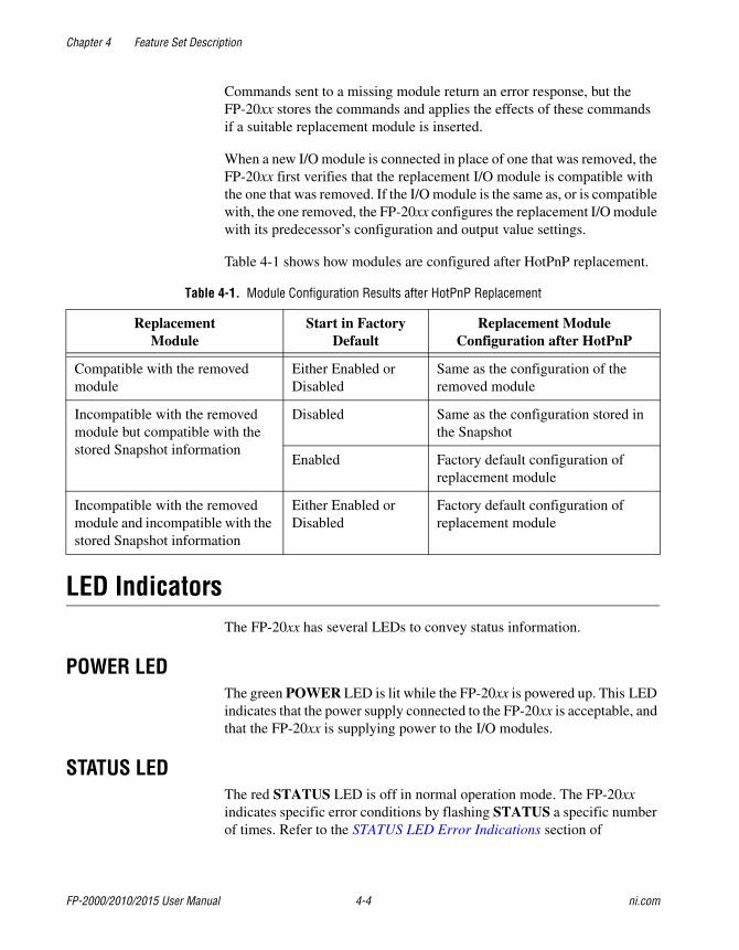
Chapter 4 Feature Set Description
FP-2000/2010/2015 User Manual 4-4 ni.com
Commands sent to a missing module return an error response, but theFP-20xx stores the commands and applies the effects of these commandsif a suitable replacement module is inserted.
When a new I/O module is connected in place of one that was removed, theFP-20xx first verifies that the replacement I/O module is compatible withthe one that was removed. If the I/O module is the same as, or is compatiblewith, the one removed, the FP-20xx configures the replacement I/O modulewith its predecessor’s configuration and output value settings.
Table 4-1 shows how modules are configured after HotPnP replacement.
LED IndicatorsThe FP-20xx has several LEDs to convey status information.
POWER LEDThe green POWER LED is lit while the FP-20xx is powered up. This LEDindicates that the power supply connected to the FP-20xx is acceptable, andthat the FP-20xx is supplying power to the I/O modules.
STATUS LEDThe red STATUS LED is off in normal operation mode. The FP-20xxindicates specific error conditions by flashing STATUS a specific numberof times. Refer to the STATUS LED Error Indications section of
Table 4-1. Module Configuration Results after HotPnP Replacement
ReplacementModule
Start in FactoryDefault
Replacement ModuleConfiguration after HotPnP
Compatible with the removedmodule
Either Enabled orDisabled
Same as the configuration of theremoved module
Incompatible with the removedmodule but compatible with thestored Snapshot information
Disabled Same as the configuration stored inthe Snapshot
Enabled Factory default configuration ofreplacement module
Incompatible with the removedmodule and incompatible with thestored Snapshot information
Either Enabled orDisabled
Factory default configuration ofreplacement module
Chapter 4 Feature Set Description
© National Instruments Corporation 4-5 FP-2000/2010/2015 User Manual
Appendix C, Troubleshooting, for more information about STATUSLED error indications.
LINK LEDThe green LINK LED is lit when the FP-20xx is connected to a functioningEthernet segment.
ACTIVE LEDThe green ACTIVE LED is lit when the FP-20xx receives data from ortransmits to the Ethernet. Because of unrelated network activity, this LEDblinks occasionally even when the FP-20xx is inactive.
100 Mbps LEDThe yellow 100 Mbps LED is lit when the FP-20xx is communicating at100 megabits per second. If the 100 Mbps LED does not light, allcommunications with the FP-20xx will be at 10 megabits per second.
User-Configurable LEDs A–D (for Count-Output Channels 5–8)LEDs A, B, C, and D correspond to count-output channels 5, 6, 7, and 8,respectively, on the network module. LEDs B, C, and D can be sent valuesof 0, 1, or 2. LED A should be sent only 0 or 1. LED A handles a 2 as a 1.The values sent to these LEDs manifest as 0 = off, 1 = green, and 2 = red.
Power-On Self Test (POST)The FP-20xx runs a power-on self test (POST) at power-up to verify itsown operational status. The test takes several seconds, does not affect theoperation of the network, and does not affect any of the field wiringconnected to the terminal bases in the bank.
If the power-on self test fails, the FP-20xx does not participate in networkcommunication, eliminating potential conflicts with the other banks in thenetwork.
When you power up the FP-20xx and it has already been configured for use,the POWER and STATUS LEDs come on for about five seconds, then theSTATUS LED turns off. The A, B, C, and D LEDs come on for about15 seconds as LabVIEW RT starts up. When they turn off, the I/O moduleREADY LEDs turn on and the network module is ready for use.
The FP-20xx indicates POST failure through the STATUS LED. If theLEDs do not follow the sequence described here, refer to the STATUS LED
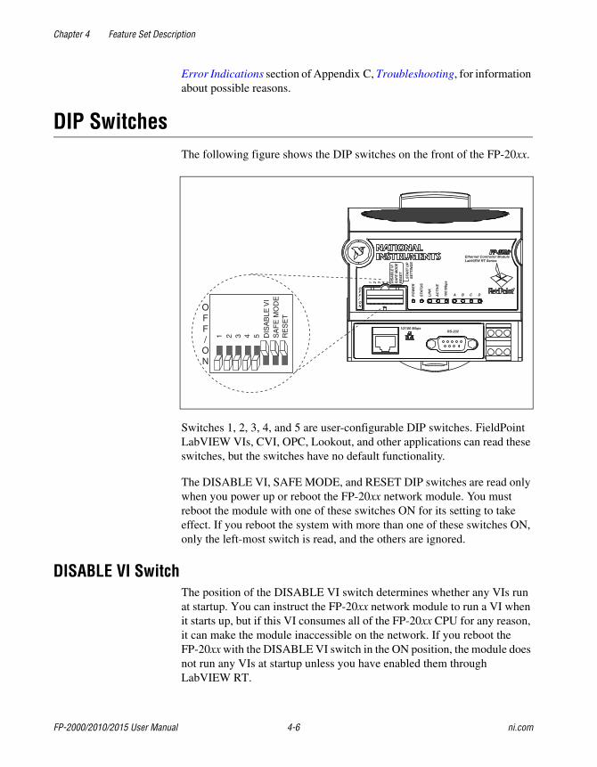
Chapter 4 Feature Set Description
FP-2000/2010/2015 User Manual 4-6 ni.com
Error Indications section of Appendix C, Troubleshooting, for informationabout possible reasons.
DIP SwitchesThe following figure shows the DIP switches on the front of the FP-20xx.
Switches 1, 2, 3, 4, and 5 are user-configurable DIP switches. FieldPointLabVIEW VIs, CVI, OPC, Lookout, and other applications can read theseswitches, but the switches have no default functionality.
The DISABLE VI, SAFE MODE, and RESET DIP switches are read onlywhen you power up or reboot the FP-20xx network module. You mustreboot the module with one of these switches ON for its setting to takeeffect. If you reboot the system with more than one of these switches ON,only the left-most switch is read, and the others are ignored.
DISABLE VI SwitchThe position of the DISABLE VI switch determines whether any VIs runat startup. You can instruct the FP-20xx network module to run a VI whenit starts up, but if this VI consumes all of the FP-20xx CPU for any reason,it can make the module inaccessible on the network. If you reboot theFP-20xx with the DISABLE VI switch in the ON position, the module doesnot run any VIs at startup unless you have enabled them throughLabVIEW RT.
1 2 3 4 5 DIS
AB
LEV
IS
AF
EM
OD
ER
ES
ET
PO
WE
R
STA
TU
S
LIN
K
AC
TIV
E
100
Mb
ps
A B C D
OFF/ON
1 2 3 4 5 DIS
AB
LEV
IS
AFE
MO
DE
RE
SE
T
Ethernet Controller ModuleLabVIEW RT Series
10/100 MbpsRS-232
OFF/ON
STA
RT
UP
SE
TTIN
GS
Chapter 4 Feature Set Description
© National Instruments Corporation 4-7 FP-2000/2010/2015 User Manual
SAFE MODE SwitchThe position of the SAFE MODE switch determines whether the FP-20xxnetwork module starts up in safe mode. If the software or configurationinformation on the module becomes corrupt or cannot be correctly read,the system may hang after being rebooted or become inaccessible over thenetwork. All LabVIEW functions are disabled in safe mode, and I/Omodule data is not accessible.
If you reboot the FP-20xx with the SAFE MODE switch in the ON position,the embedded LabVIEW RT engine does not start; the module starts up insafe mode. Now you can reconfigure the TCP/IP settings, download newsoftware using Remote System Explorer, and reboot the FP-20xx with theSAFE MODE switch in the OFF position.
RESET SwitchThe position of the RESET switch determines whether the IP settings of theFP-20xx network module are reset at startup. Reset the TCP/IP settings ifyou are moving the module from one subnet to another or if you suspectthat the current TCP/IP settings are bad. Refer to Appendix B, Resetting theFP-20xx, for more information about the procedure for resetting theFP-20xx.
User-Configurable DIP Switches 1–5 (for Discrete Input Channels 0–4)DIP switches 1–5 can be read as discrete input channels 0–4 on the networkmodule.
Serial PortThe RS-232 serial port can be accessed using the Serial Port VIs.The RS-232 port is considered port 0 and is a DTE port. Refer to theFP-20xx Hardware Overview section of Chapter 1, Overview of theFP-20xx Network Module, for the location of this port. If you are notrunning an embedded application, you must target the FP-20xx in orderto access the serial port. Refer to Chapter 5, LabVIEW RT Programming,for more information about targeting the FP-20xx.

Chapter 4 Feature Set Description
FP-2000/2010/2015 User Manual 4-8 ni.com
Isolated Power Connector (Channel 9)The FP-20xx power connector is a 6-pin screw-terminal connector thataccommodates both primary and backup power supplies. The FP-20xx usesthe power supply with the higher voltage level, indicating which supply itis using on channel 9. A value of 0 indicates the primary supply, and a valueof 1 indicates the backup supply.
© National Instruments Corporation 5-1 FP-2000/2010/2015 User Manual
5LabVIEW RT Programming
This chapter contains specific information about targeting LabVIEWReal-Time (RT) to the FP-20xx module, network options for restrictingaccess to your module, embedding LabVIEW RT applications on yourmodule, and launching embedded applications when your module starts up.For general LabVIEW RT programming information, refer to the LabVIEWRT User Manual.
Targeting LabVIEW RT to a PlatformYou can target LabVIEW RT to your FP-20xx or the host PC. When youselect a target platform other than the host PC, the RT Development Systemdownloads any LabVIEW RT application you subsequently run to theselected target platform. Refer to Chapter 1, Introduction, and to Chapter 3,Software Overview, of the LabVIEW RT User Manual for moreinformation about the RT Development System.
Targeting LabVIEW RT to the FP-20xxWhen you target LabVIEW RT to your FP-20xx, you can runLabVIEW RT applications on the controller. However, when targeted toyour FP-20xx, LabVIEW RT lacks some features found in LabVIEW forWindows because the controller does not have all the software of a PC.The following LabVIEW functions are not supported in LabVIEW RTwhen targeted to your FP-20xx:
• ActiveX
• Front panel datalogging
• Dialog boxes
• Printing
• Programmatic menus
• VISA
• Front panel Web publishing
• NI-DAQ
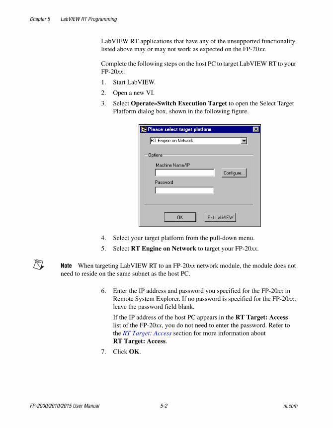
Chapter 5 LabVIEW RT Programming
FP-2000/2010/2015 User Manual 5-2 ni.com
LabVIEW RT applications that have any of the unsupported functionalitylisted above may or may not work as expected on the FP-20xx.
Complete the following steps on the host PC to target LabVIEW RT to yourFP-20xx:
1. Start LabVIEW.
2. Open a new VI.
3. Select Operate»Switch Execution Target to open the Select TargetPlatform dialog box, shown in the following figure.
4. Select your target platform from the pull-down menu.
5. Select RT Engine on Network to target your FP-20xx.
Note When targeting LabVIEW RT to an FP-20xx network module, the module does notneed to reside on the same subnet as the host PC.
6. Enter the IP address and password you specified for the FP-20xx inRemote System Explorer. If no password is specified for the FP-20xx,leave the password field blank.
If the IP address of the host PC appears in the RT Target: Accesslist of the FP-20xx, you do not need to enter the password. Refer tothe RT Target: Access section for more information aboutRT Target: Access.
7. Click OK.
Chapter 5 LabVIEW RT Programming
© National Instruments Corporation 5-3 FP-2000/2010/2015 User Manual
Targeting LabVIEW RT to the Host PCWhen you target LabVIEW RT to the host PC, you can use LabVIEW RTlike LabVIEW for Windows.
Perform the following steps to target LabVIEW RT to the host PC:
1. Perform steps 1 through 4 of the Targeting LabVIEW RT to theFP-20xx section.
2. Select Host PC (LabVIEW for Windows).
3. Click OK.
Note Applications running on the host PC communicate to FieldPoint I/O channels.However, serial communication will be routed to the host PC serial port rather than theFP-20xx serial port. In this case, VIs that use the serial port will communicate via the hostPC serial port. Also, when running on a host, deadbands apply to FieldPoint I/O channels.
Network OptionsWhen you target LabVIEW RT to a networked FP-20xx, selectTools»Options to access LabVIEW options. The options in the Optionsmenu only apply to the RT Development System running on the host PC.
You also can set options for the RT Engine on the FP-20xx when you targetLabVIEW RT to the controller. With LabVIEW RT targeted to yourFP-20xx, select Tools»Network Options to access RT Engine options.RT Engine options apply to LabVIEW RT applications running on theFP-20xx. The Performance and Disk, VI Server, and Web Server optiondialog boxes are identical to the normal LabVIEW option dialog boxes.However, the settings are applied to the FP-20xx. Refer to theLabVIEW Help for more information about Performance and Disk,VI Server, and Web Server options.
You also can use the following two additional groups of options forLabVIEW RT applications on networked FP-20xx modules:RT Target: Access and RT Target: Miscellaneous.
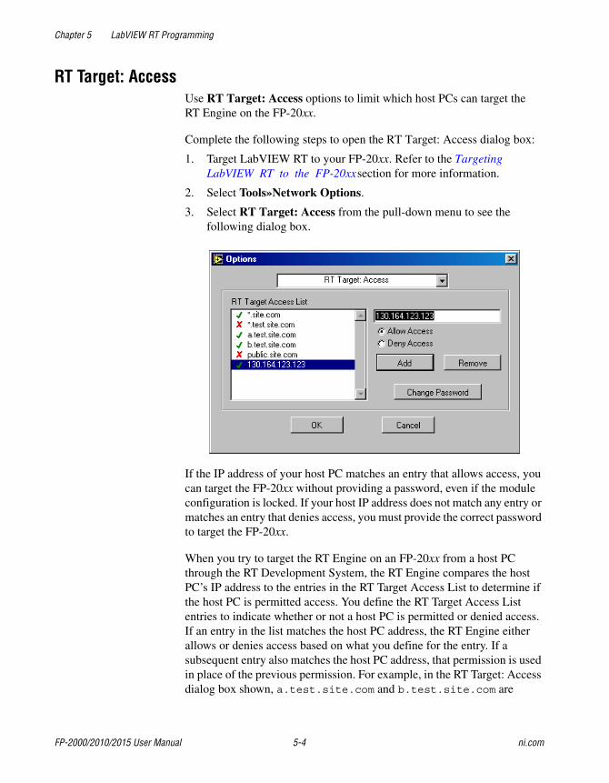
Chapter 5 LabVIEW RT Programming
FP-2000/2010/2015 User Manual 5-4 ni.com
RT Target: AccessUse RT Target: Access options to limit which host PCs can target theRT Engine on the FP-20xx.
Complete the following steps to open the RT Target: Access dialog box:
1. Target LabVIEW RT to your FP-20xx. Refer to the TargetingLabVIEW RT to the FP-20xx section for more information.
2. Select Tools»Network Options.
3. Select RT Target: Access from the pull-down menu to see thefollowing dialog box.
If the IP address of your host PC matches an entry that allows access, youcan target the FP-20xx without providing a password, even if the moduleconfiguration is locked. If your host IP address does not match any entry ormatches an entry that denies access, you must provide the correct passwordto target the FP-20xx.
When you try to target the RT Engine on an FP-20xx from a host PCthrough the RT Development System, the RT Engine compares the hostPC’s IP address to the entries in the RT Target Access List to determine ifthe host PC is permitted access. You define the RT Target Access Listentries to indicate whether or not a host PC is permitted or denied access.If an entry in the list matches the host PC address, the RT Engine eitherallows or denies access based on what you define for the entry. If asubsequent entry also matches the host PC address, that permission is usedin place of the previous permission. For example, in the RT Target: Accessdialog box shown, a.test.site.com and b.test.site.com are
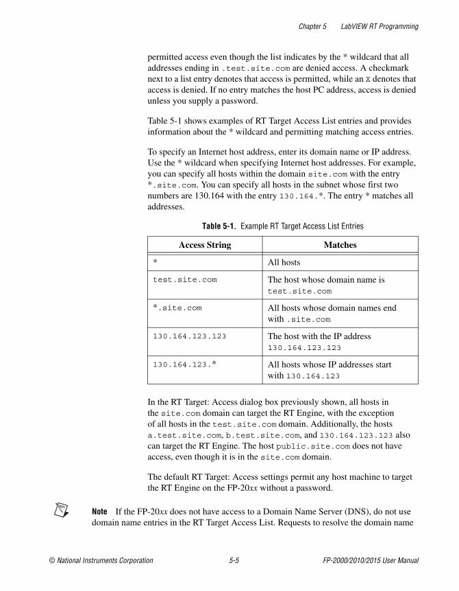
Chapter 5 LabVIEW RT Programming
© National Instruments Corporation 5-5 FP-2000/2010/2015 User Manual
permitted access even though the list indicates by the * wildcard that alladdresses ending in .test.site.com are denied access. A checkmarknext to a list entry denotes that access is permitted, while an X denotes thataccess is denied. If no entry matches the host PC address, access is deniedunless you supply a password.
Table 5-1 shows examples of RT Target Access List entries and providesinformation about the * wildcard and permitting matching access entries.
To specify an Internet host address, enter its domain name or IP address.Use the * wildcard when specifying Internet host addresses. For example,you can specify all hosts within the domain site.com with the entry*.site.com. You can specify all hosts in the subnet whose first twonumbers are 130.164 with the entry 130.164.*. The entry * matches alladdresses.
In the RT Target: Access dialog box previously shown, all hosts inthe site.com domain can target the RT Engine, with the exceptionof all hosts in the test.site.com domain. Additionally, the hostsa.test.site.com, b.test.site.com, and 130.164.123.123 alsocan target the RT Engine. The host public.site.com does not haveaccess, even though it is in the site.com domain.
The default RT Target: Access settings permit any host machine to targetthe RT Engine on the FP-20xx without a password.
Note If the FP-20xx does not have access to a Domain Name Server (DNS), do not usedomain name entries in the RT Target Access List. Requests to resolve the domain name
Table 5-1. Example RT Target Access List Entries
Access String Matches
* All hosts
test.site.com The host whose domain name istest.site.com
*.site.com All hosts whose domain names endwith .site.com
130.164.123.123 The host with the IP address130.164.123.123
130.164.123.* All hosts whose IP addresses startwith 130.164.123
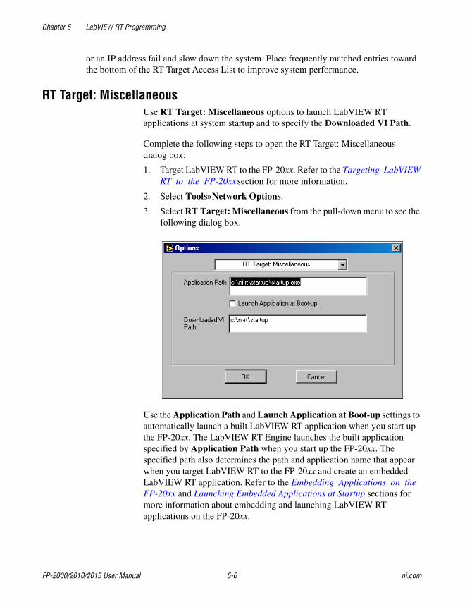
Chapter 5 LabVIEW RT Programming
FP-2000/2010/2015 User Manual 5-6 ni.com
or an IP address fail and slow down the system. Place frequently matched entries towardthe bottom of the RT Target Access List to improve system performance.
RT Target: MiscellaneousUse RT Target: Miscellaneous options to launch LabVIEW RTapplications at system startup and to specify the Downloaded VI Path.
Complete the following steps to open the RT Target: Miscellaneousdialog box:
1. Target LabVIEW RT to the FP-20xx. Refer to the Targeting LabVIEWRT to the FP-20xx section for more information.
2. Select Tools»Network Options.
3. Select RT Target: Miscellaneous from the pull-down menu to see thefollowing dialog box.
Use the Application Path and Launch Application at Boot-up settings toautomatically launch a built LabVIEW RT application when you start upthe FP-20xx. The LabVIEW RT Engine launches the built applicationspecified by Application Path when you start up the FP-20xx. Thespecified path also determines the path and application name that appearwhen you target LabVIEW RT to the FP-20xx and create an embeddedLabVIEW RT application. Refer to the Embedding Applications on theFP-20xx and Launching Embedded Applications at Startup sections formore information about embedding and launching LabVIEW RTapplications on the FP-20xx.
Chapter 5 LabVIEW RT Programming
© National Instruments Corporation 5-7 FP-2000/2010/2015 User Manual
Select Launch Application at Boot-up to launch the application specifiedin Application Path when you start up the FP-20xx. You must first createthe application using the Application Builder before you select this option.Refer to the LabVIEW Application Builder Release Notes and to theLabVIEW Help for more information about the Application Builder. Referto the Embedding Applications on the FP-20xx section for moreinformation about creating LabVIEW RT applications.
By changing the Application Path, you can create multiple LabVIEW RTapplications on the FP-20xx. However, only the application you specifyin the Application Path launches at startup, if you select LaunchApplication at Boot-up.
Use Downloaded VI Path to specify the default path for the RT Engine VIsdownloaded by the RT Development System. VIs are stored on the host PChard drive and are opened in the host RT Development System. Therefore,the RT Engine does not know the actual path of the downloaded VIs.The RT Engine uses the path specified in Downloaded VI Path foroperations that require the VI path. For example, the file constant CurrentVI’s Path normally returns the path of the VI in which the constant is used.This constant may be used in a VI that reads or writes data to a file on thedisk. When you run this VI in the LabVIEW RT Engine on the FP-20xx,Current VI’s Path returns the path specified in the Downloaded VI Pathoption, appended with the name of the VI.
Embedding Applications on the FP-20xxLabVIEW RT applications built on the host PC with the ApplicationBuilder can be embedded on your FP-20xx. This section explains how toembed LabVIEW RT applications on your FP-20xx by using theApplication Builder while LabVIEW RT is targeted to the controller.
Refer to Chapter 3, Software Overview, of the LabVIEW RT User Manualfor more information about building LabVIEW RT applications on the hostPC. Refer to the LabVIEW Application Builder Release Notes and to theLabVIEW Help for more information about using the Application Builderon the host PC.
Command Line ArgumentsUse command line arguments for applications built on the host PC todisable the Select Target Platform dialog box and explicitly specify a targetfor the application. You can use these command line arguments ina shortcut from your Windows Startup folder to automatically launch
Chapter 5 LabVIEW RT Programming
FP-2000/2010/2015 User Manual 5-8 ni.com
RT Engine applications and/or host PC applications when you start up yourhost PC.
For example, create a shortcut with the following shortcut target:
c:\mybuiltapp.exe -target 127.127.44.108 –quithost
To disable the Select Target Platform dialog box, specify a target, suchas the IP address of the FP-20xx, in the command line argument of yourbuilt application using -target. For example,
c:\mybuiltapp_rtengine.exe -target 127.127.44.108
or
c:\mybuiltapp_host.exe -target host
To disconnect the host PC from the RT Engine after all applications aredownloaded, use -quithost. For example,
c:\mybuiltapp_rtengine.exe -target 127.127.44.108
-quithost
Using Application BuilderWhen you target LabVIEW RT to your FP-20xx, use the ApplicationBuilder to embed LabVIEW RT applications on your FP-20xx.
Complete the following steps to embed LabVIEW RT applications on yourFP-20xx using the Application Builder:
1. Target LabVIEW RT to your FP-20xx. Refer to the TargetingLabVIEW RT to the FP-20xx section for more information.
2. Open a new VI.
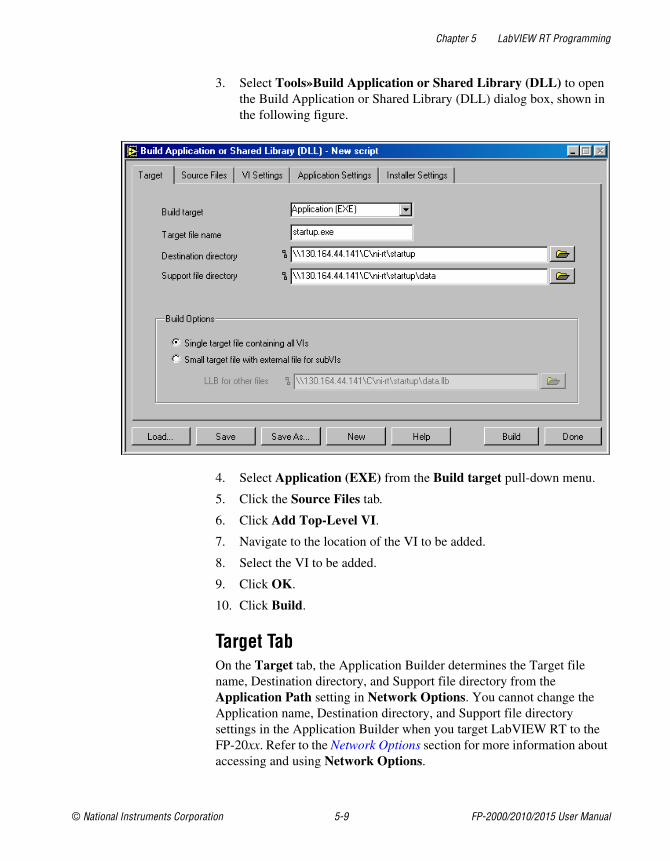
Chapter 5 LabVIEW RT Programming
© National Instruments Corporation 5-9 FP-2000/2010/2015 User Manual
3. Select Tools»Build Application or Shared Library (DLL) to openthe Build Application or Shared Library (DLL) dialog box, shown inthe following figure.
4. Select Application (EXE) from the Build target pull-down menu.
5. Click the Source Files tab.
6. Click Add Top-Level VI.
7. Navigate to the location of the VI to be added.
8. Select the VI to be added.
9. Click OK.
10. Click Build.
Target TabOn the Target tab, the Application Builder determines the Target filename, Destination directory, and Support file directory from theApplication Path setting in Network Options. You cannot change theApplication name, Destination directory, and Support file directorysettings in the Application Builder when you target LabVIEW RT to theFP-20xx. Refer to the Network Options section for more information aboutaccessing and using Network Options.
Chapter 5 LabVIEW RT Programming
FP-2000/2010/2015 User Manual 5-10 ni.com
If you select Small target with external file for subVIs in the BuildOptions pane, you cannot change the LLB for other files path because thispath is determined from the Application Path setting in NetworkOptions. Refer to the LabVIEW Help for more information about the Smalltarget with external file for subVIs option. Refer to the Network Optionssection for more information about accessing and using Network Options.
Source Files and VI Settings TabsUse the Source Files and VI Settings tabs the same way you do to build aLabVIEW RT application when LabVIEW RT is targeted to the host PC.Refer to the LabVIEW Help for more information about the Source Filesand VI Settings tabs.
Caution Do not add the file serpdrv to your application in the Source Files tab.The serial port driver is installed on the FP-20xx with the RT Engine. Manually addingserpdrv to your application adds the Windows driver, which is not compatible with theLabVIEW RT Engine on the FP-20xx.
Application Settings and Installer Settings TabsThe Application Settings and Installer Settings tabs are disabled whenyou target LabVIEW RT to the FP-20xx because these settings do not applyto applications embedded on the controller.
Launching Embedded Applications at StartupThe RT Engine can launch your embedded application each time you startup your FP-20xx. Complete the following steps to launch your embeddedapplication each time the FP-20xx starts up:
1. Target LabVIEW RT to the FP-20xx. Refer to the Targeting LabVIEWRT to the FP-20xx section for more information.
2. Select Tools»Network Options.
3. Select RT Target: Miscellaneous from the pull-down menu.
4. Select Launch Application at Boot-up.
5. Click OK.
Chapter 5 LabVIEW RT Programming
© National Instruments Corporation 5-11 FP-2000/2010/2015 User Manual
File Transfer CapabilityWhen running on an FP-20xx, the RT Engine has a File Transfer Protocol(FTP) server. The FTP server gives you the ability to use any standard FTPutility for transferring files to and from the hard drive of the FP-20xx.You must provide the correct password when opening a connection to theFP-20xx if the configuration is locked in Remote System Explorer.
Note Transferred files must use the 8.3 file naming convention.
For programmatic file transfer control in LabVIEW or LabVIEW RT,use the Internet Developers Toolkit, included in the LabVIEW EnterpriseConnectivity Toolset. Refer to the National Instruments Web site at ni.comfor more information about purchasing and using the LabVIEW EnterpriseConnectivity Toolset.
Note Contact NI to determine whether the toolkit version you are using can bedownloaded onto the FP-20xx.
Hardware WatchdogIn addition to the network watchdog described in Chapter 4, Feature SetDescription, the FP-20xx network modules support the hardware watchdogavailable in LabVIEW RT. You can use the hardware watchdog to verifyprogrammatically that the FP-20xx is responding within a given timeperiod. If the module stops responding because of a problem in theprogram, it can be configured to reset the FP-20xx or generate anoccurrence in LabVIEW.
The hardware watchdog VIs are on the FieldPoint palette atFieldPoint»FieldPoint RT»FieldPoint Watchdog. For examples thatshow how to use the hardware watchdog, refer to the RT Watchdog(PXI-8156B).llb file installed under \\examples\rt\. For additionalinformation, refer to the help for the watchdog VIs.
© National Instruments Corporation A-1 FP-2000/2010/2015 User Manual
AChoosing Network Settings
This appendix describes how to choose appropriate network settings.
Choosing an IP AddressThe way you choose an IP address for your FP-20xx may depend onwhether your network has a system administrator.
Choosing an IP Address with a Network AdministratorIf you are adding the FP-20xx to an existing Ethernet network, you mustchoose IP addresses carefully. Consult with your network administrator toobtain appropriate values:
• Ask the administrator to provide static IP addresses to your FP-20xxand to the computer running the National Instruments Time Service.Time Service is installed along with the FieldPoint software and runsautomatically.
• Ask the network administrator to provide the proper subnet mask,gateway, and DNS server addresses.
Choosing an IP Address without a Network AdministratorIf you are assembling your own small Ethernet network, you can chooseyour own IP address. The following guidelines may help you chooseappropriate values:
• IP Addresses are generally in the form of w.x.y.z where w, x, and yare numbers between 0 and 255 (inclusive) and z is between 1 and 254;however, a z value of 1 is usually reserved for the IP address of agateway.
• Local networks (those that will not be connected to the Internet) shouldhave IP addresses assigned from the following ranges:
– 10.0.0.0 through 10.255.255.255
– 172.16.0.0 through 172.31.255.255
– 192.168.0.0 through 192.168.255.255
Appendix A Choosing Network Settings
FP-2000/2010/2015 User Manual A-2 ni.com
• To determine whether an IP address is already used by another deviceon the network, select Start»Run, type ping x.x.x.x wherex.x.x.x is the IP address you want to test, and click OK. If pingreturns a timeout, the IP address is not used. If it returns a reply froma device, the IP address is already in use.
• A subnet is a set of systems whose IP addresses are configured suchthat they can communicate directly with one another. Data does notflow through an intermediate router. The most common subnet mask is255.255.255.0.
• Appropriate subnet masks should be chosen to divide your system intosmaller subnets, as desired. The method for determining the subnet isas follows:
The IP Address is combined in a logical AND with the subnet mask todetermine the subnet. For example, a system with an IP address of10.10.10.10 and a subnet mask of 255.255.255.0 is on thesubnet of 10.10.10.x. Thus, all systems with an IP of 10.10.10.xand a subnet mask of 255.255.255.0 are considered to be on thesame subnet. Likewise, if the systems have a subnet mask of255.255.0.0, all systems with an IP of 10.10.x.x are consideredpart of the same subnet.
• Using the Suggest Values button when configuring a networkmodule’s IP address in FieldPoint Explorer should result in values thatwork on your network.
• The Time Server is the address of the computer where you haveinstalled the National Instruments Time Service. This service isinstalled along with the FieldPoint software, Lookout 4.0 or later,and the LabVIEW Datalogging and Supervisory Control module.
• If you are setting up your own network, you probably do not have agateway or DNS server, so you should set these values to 0.0.0.0.
• To find out the network settings for your computer, run ipconfig onWindows 2000/NT/XP or winipcfg on Windows 98/95.
To run winipcfg, select Start»Run, type winipcfg in the Openfield, and click OK. The IP Configuration window appears, whichgives you information about the network setup for your computer.Make sure that the correct Ethernet adapter appears in the field atthe top of the window.
To run ipconfig, open a Command window, type ipconfig at theprompt, and press <Enter>. If you need more information, you can runipconfig with the /all option by typing ipconfig /all. Makesure you use the settings for the correct Ethernet adapter to configureyour FP-20xx.
Appendix A Choosing Network Settings
© National Instruments Corporation A-3 FP-2000/2010/2015 User Manual
Giving Your FP-20xx a Host NameFollow these steps to give your FP-20xx a hostname:
1. Right-click the Comm Resource in FieldPoint Explorer, and chooseEdit this comm resource.
2. Click Browse to launch Remote System Explorer.
3. Double-click the serial number of the module for which you want toenter a host name.
4. On the System tab of the System Configuration dialog box, enter aname in the Host Name field.
5. On the Network Settings tab of the System Configuration dialog box,make sure the DNS Address value points to correct location.
6. If your network has a DNS server, ask your network administrator toadd a table entry for your host name.
If your network does not have a DNS server, you need to set up thehosts files on each networked computer. A hosts file allows anetworked computer to use host names when no DNS server isavailable. Each computer on the network that needs to access theFP-20xx should have a properly configured hosts file.
Setting up a Hosts File Under Windows 2000/NT/XP1. Log on as an administrator to the local machine (not onto a domain).
2. Create a text file called hosts. This file has to be placed in thesystem32\drivers\etc directory of the system root, for example:c:\winnt\system32\drivers\etc\hosts
3. The file should include the following lines, where hostname is thehost name of the FP-20xx and 12.34.56.78 is its IP address:
127.0.0.1 localhost12.34.56.78 hostname
Setting Up a Hosts File Under Windows 98/951. Create a text file called hosts. This file has to be placed in the
windows directory, for example c:\windows\hosts
2. The file should include the following lines, where fp is the host name of the FP-20xx and 12.34.56.78 is its IP address:
127.0.0.1 localhost
12.34.56.78 fp
Appendix A Choosing Network Settings
FP-2000/2010/2015 User Manual A-4 ni.com
Viewing and Editing the FP-20xx TCP/IP SettingsFollow these steps to view the TCP/IP settings:
1. In FieldPoint Explorer, right-click the Comm Resource and select Editthis comm resource.
2. Click Browse to launch Remote System Explorer.
3. In Remote System Explorer, double-click the serial number of theFP-20xx whose settings you would like to view or change.
4. When you are done, click OK. Click Cancel to discard any changesyou have made.
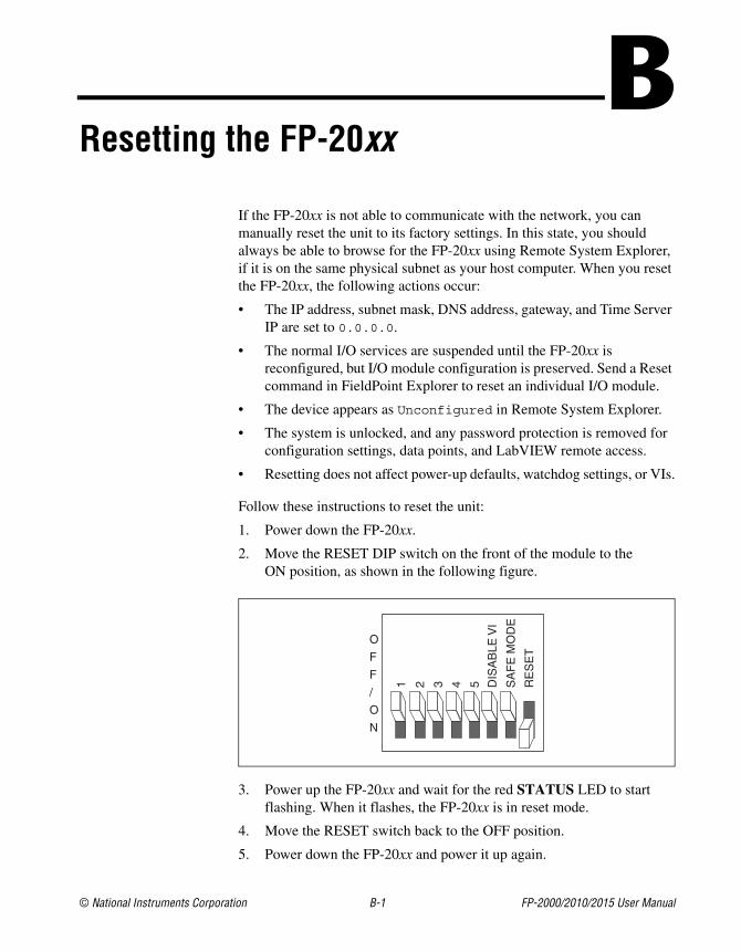
© National Instruments Corporation B-1 FP-2000/2010/2015 User Manual
BResetting the FP-20xx
If the FP-20xx is not able to communicate with the network, you canmanually reset the unit to its factory settings. In this state, you shouldalways be able to browse for the FP-20xx using Remote System Explorer,if it is on the same physical subnet as your host computer. When you resetthe FP-20xx, the following actions occur:
• The IP address, subnet mask, DNS address, gateway, and Time ServerIP are set to 0.0.0.0.
• The normal I/O services are suspended until the FP-20xx isreconfigured, but I/O module configuration is preserved. Send a Resetcommand in FieldPoint Explorer to reset an individual I/O module.
• The device appears as Unconfigured in Remote System Explorer.
• The system is unlocked, and any password protection is removed forconfiguration settings, data points, and LabVIEW remote access.
• Resetting does not affect power-up defaults, watchdog settings, or VIs.
Follow these instructions to reset the unit:
1. Power down the FP-20xx.
2. Move the RESET DIP switch on the front of the module to theON position, as shown in the following figure.
3. Power up the FP-20xx and wait for the red STATUS LED to startflashing. When it flashes, the FP-20xx is in reset mode.
4. Move the RESET switch back to the OFF position.
5. Power down the FP-20xx and power it up again.
1 2 3 4 5 DIS
AB
LEV
I
SA
FE
MO
DE
RE
SE
T
O
F
F
/
O
N
© National Instruments Corporation C-1 FP-2000/2010/2015 User Manual
CTroubleshooting
This appendix gives troubleshooting instructions for the FP-20xx andFieldPoint software.
Software Configuration Problems
Error when Browsing in Comm Resource Configuration Dialog BoxPossible causes and solutions:
• Your Ethernet adapter is not installed properly. To install your Ethernetadapter, select Start»Settings»Control Panel and double-clickNetwork. Your Ethernet adapter should appear in the list of installedcomponents. If it does not appear, reinstall the software that came withyour Ethernet adapter. If you do not have this software, contact theEthernet adapter manufacturer.
• Your Ethernet adapter is installed, but TCP/IP protocol is not.TCP/IP is the network protocol used to communicate over Ethernetto the FP-20xx. Select Start»Settings»Control Panel anddouble-click Network. TCP/IP should appear in the list of installednetwork components. If it does not appear, select Protocol from theNetwork Component Type dialog box and click Add. In the SelectNetwork Protocol dialog box that appears, select Microsoft as themanufacturer and TCP/IP from the Network protocol list. Click OK.You may need the Microsoft Windows diskettes or CD that came withyour computer, and you may have to restart your computer afterclosing the Network control panel.
FP-20xx Does Not Appear in Remote SystemExplorer Dialog Box When Browsing
Possible causes and solutions:
• Verify that there is power to the FP-20xx, and that both the module andthe computer are properly connected to the Ethernet network. Themodule’s POWER and LINK LED indicators should be lit. When youclick Browse, the ACTIVE LED on the FP-20xx should flash toindicate that communications are taking place.
Appendix C Troubleshooting
FP-2000/2010/2015 User Manual C-2 ni.com
• Certain network devices, such as switches and routers, may filter outthe directed UDP broadcast packets which FieldPoint Explorer uses tocommunicate with unconfigured FP-20xx modules, even if they are onthe same subnet as the computer running FieldPoint Explorer. You cantest this by connecting the computer running FieldPoint Explorer andthe FP-20xx directly to a simple Ethernet hub or by using a crossovercable between the FP-20xx and the host PC. If the FP-20xx appears inthe Remote System Explorer window using this configuration, but notwhen connected to the larger network, it is likely that there is aproblem of this type. Consult your network administrator.
• The FP-20xx may have been configured on another network and thenmoved to the current network. Refer to Appendix B, Resetting theFP-20xx, for instructions on resetting the FP-20xx.
• You may be using the wrong type of Ethernet cable.
• You may have assigned an IP address to your FP-20xx that is alreadyused by another device on the network. Either remove or reconfigurethe other device, or reconfigure the FP-20xx IP address. Refer toAppendix A, Choosing Network Settings, for information on choosingIP settings.
Error when Configuring IP Settings for the FP-20xxPossible causes and solutions: Make sure you are entering valid values forall network parameters. If the subnet mask or IP address is not compatiblewith the network settings, an error is returned and the FP-20xx is notconfigured.
FP-20xx Returns Invalid Timestamp ValuesPossible causes and solutions:
• Verify that the IP address entered in Remote System Explorer points toa computer running National Instruments Time Service.
• Verify that the time zone settings are set correctly on the host PC andTime Server PC.
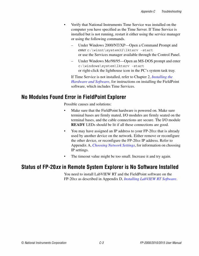
Appendix C Troubleshooting
© National Instruments Corporation C-3 FP-2000/2010/2015 User Manual
• Verify that National Instruments Time Service was installed on thecomputer you have specified as the Time Server. If Time Service isinstalled but is not running, restart it either using the service manageror using the following commands.
– Under Windows 2000/NT/XP—Open a Command Prompt andenter c:\winnt\system32\lktsrv -startor use the Services manager available through the Control Panel.
– Under Windows Me/98/95—Open an MS-DOS prompt and enterc:\windows\system\lktsrv -start
or right-click the lighthouse icon in the PC’s system task tray.
If Time Service is not installed, refer to Chapter 2, Installing theHardware and Software, for instructions on installing the FieldPointsoftware, which includes Time Services.
No Modules Found Error in FieldPoint ExplorerPossible causes and solutions:
• Make sure that the FieldPoint hardware is powered on. Make sureterminal bases are firmly mated, I/O modules are firmly seated on theterminal bases, and the cable connections are secure. The I/O moduleREADY LEDs should be lit if all these connections are good.
• You may have assigned an IP address to your FP-20xx that is alreadyused by another device on the network. Either remove or reconfigurethe other device, or reconfigure the FP-20xx IP address. Refer toAppendix A, Choosing Network Settings, for information on choosingIP settings.
• The timeout value might be too small. Increase it and try again.
Status of FP-20xx in Remote System Explorer is No Software InstalledYou need to install LabVIEW RT and the FieldPoint software on theFP-20xx as described in Appendix D, Installing LabVIEW RT Software.
Appendix C Troubleshooting
FP-2000/2010/2015 User Manual C-4 ni.com
Runaway Start-Up ApplicationIf a runaway startup application causes the FP-20xx to becomeunresponsive, you must power down the FP-20xx, then reboot it with eitherthe DISABLE VI switch or SAFE MODE switch in the ON position.Restarting the module with the DISABLE VI switch ON prevents any VIsfrom running at startup. Restarting it with the SAFE MODE switch ONstarts the FP-20xx in safe mode, and the embedded LabVIEW RT engine isnot launched. Refer to the DIP Switches section of Chapter 4, Feature SetDescription, for more information about these DIP switches.
STATUS LED Error IndicationsThe FP-20xx indicates specific error conditions by flashing the redSTATUS LED a specific number of times. The following table describesthe STATUS LED flashing sequences and the corresponding errorcondition.
Table C-1. STATUS LED Flashes and Corresponding Error Conditions
Numberof Flashes Error Condition
0 (stays lit) The FP-20xx did not power on correctly. ContactNational Instruments for assistance.
1 The FP-20xx is in reset mode or is unconfigured.Refer to Appendix B, Resetting the FP-20xx, for moreinformation about reset mode. Refer to Chapter 3,Hardware and Software Configuration, for moreinformation about configuration.
2 The FP-20xx has detected an error in its firmware. Thisusually occurs when an attempt to upgrade the firmwareis interrupted. Repeat the firmware upgrade process.
3 The FP-20xx is in safe mode. Download the software asdescribed in Appendix D, Installing LabVIEW RTSoftware.
4 (or more) The FP-20xx has detected an unrecoverable error.Contact National Instruments for assistance.
© National Instruments Corporation D-1 FP-2000/2010/2015 User Manual
DInstalling LabVIEW RT Software
Viewing Information about Installed SoftwareTo view the software installed on your FP-20xx, right-click the FP-20xxin Remote System Explorer and select View Installed Software. If yourFP-20xx has LabVIEW RT installed, the Currently Installed Softwaredialog box displays the software and version numbers, as shown in thefollowing figure.
Installing or Upgrading LabVIEW RT on the FP-20xxYour FP-20xx has LabVIEW RT pre-installed. However, if the FP-20xxSTATUS LED flashes three times, and its status in Remote SystemExplorer is No software installed, the FP-20xx is in safe mode. In thiscase, you should re-install or upgrade the LabVIEW RT software.
Complete the following steps to install or upgrade the LabVIEW RTsoftware on your FP-20xx:
1. Run Remote System Explorer: right-click the Comm Resource inFieldPoint Explorer, choose Edit this comm resource, and clickBrowse.
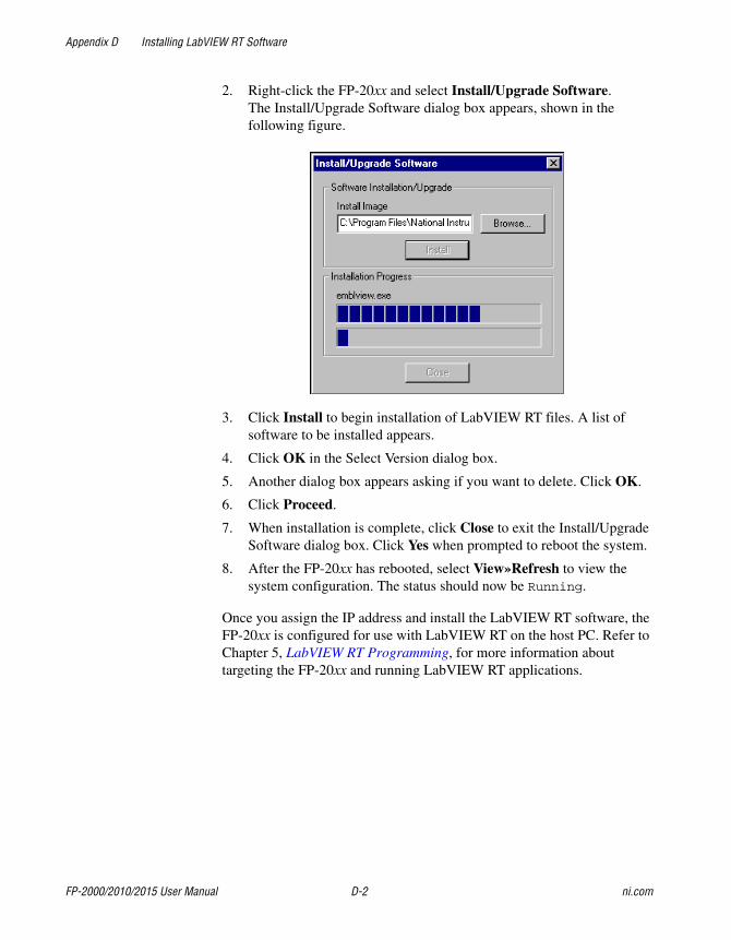
Appendix D Installing LabVIEW RT Software
FP-2000/2010/2015 User Manual D-2 ni.com
2. Right-click the FP-20xx and select Install/Upgrade Software.The Install/Upgrade Software dialog box appears, shown in thefollowing figure.
3. Click Install to begin installation of LabVIEW RT files. A list ofsoftware to be installed appears.
4. Click OK in the Select Version dialog box.
5. Another dialog box appears asking if you want to delete. Click OK.
6. Click Proceed.
7. When installation is complete, click Close to exit the Install/UpgradeSoftware dialog box. Click Yes when prompted to reboot the system.
8. After the FP-20xx has rebooted, select View»Refresh to view thesystem configuration. The status should now be Running.
Once you assign the IP address and install the LabVIEW RT software, theFP-20xx is configured for use with LabVIEW RT on the host PC. Refer toChapter 5, LabVIEW RT Programming, for more information abouttargeting the FP-20xx and running LabVIEW RT applications.
© National Instruments Corporation E-1 FP-2000/2010/2015 User Manual
ESpecifications
NetworkNetwork interface................................... 10BaseT and 100BaseTX
Ethernet
Compatibility ......................................... IEEE802.3
Communication rates ............................. 10 Mbps, 100 Mbps,auto-negotiated
Maximum cabling distance .................... 100 m/segment
Maximum power to connectedterminal bases......................................... 9 W
Maximum number of banks ................... Determined by network topology
MemoryFP-2000.................................................. 16 MB nonvolatile
16 MB DRAM
FP-2010.................................................. 32 MB nonvolatile32 MB DRAM
FP-2015.................................................. 512 MB nonvolatile32 MB DRAM
Power RequirementPower supply range................................ 11 to 30 VDC
Power consumption................................ 4.5 W + 1.1 * ∑(I/O ModuleConsumption)

Appendix E Specifications
FP-2000/2010/2015 User Manual E-2 ni.com
Physical CharacteristicsScrew-terminal wiring ............................16–26 AWG copper conductor
wire with 7 mm (0.28 in.) ofinsulation stripped from the end
Torque for screw terminals.....................0.5–0.6 N ⋅ m (4.4–5.3 lb ⋅ in.)
Weight ....................................................278 g (9.8 oz)
EnvironmentalFieldPoint modules are intended for indoor use only.
Operating temperature ............................–25 to 55 °C
Storage temperature ................................–40 to 85 °C
Humidity .................................................10 to 90% RH, noncondensing
Maximum altitude...................................2,000 m
Pollution Degree .....................................2
SafetyThe FP-20xx meets the requirements of the following standards for safetyand electrical equipment for measurement, control, and laboratory use:
• EN 61010-1:1993/A2:1995, IEC 61010-1:1990/A2:1995
• UL 3101-1:1993, UL 3111-1:1994, UL 3121:1998
• CAN/CSA c22.2 no. 1010.1:1992/A2:1997
Electromagnetic CompatibilityCE, C-Tick and FCC Part 15 (Class A) Compliant
Electrical emissions ................................EN 55011 Class A at 10 m FCCPart 15A above 1 GHz
Electrical immunity ................................Evaluated to EN 61326: 1997/A1:1998, Table 1
Note For full EMC compliance, you must operate this device with shielded cabling. Inaddition, all cover and filler panels must be installed. See the Declaration of Conformity
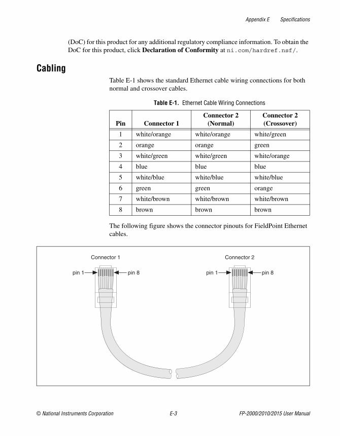
Appendix E Specifications
© National Instruments Corporation E-3 FP-2000/2010/2015 User Manual
(DoC) for this product for any additional regulatory compliance information. To obtain theDoC for this product, click Declaration of Conformity at ni.com/hardref.nsf/.
CablingTable E-1 shows the standard Ethernet cable wiring connections for bothnormal and crossover cables.
The following figure shows the connector pinouts for FieldPoint Ethernetcables.
Table E-1. Ethernet Cable Wiring Connections
Pin Connector 1Connector 2
(Normal)Connector 2(Crossover)
1 white/orange white/orange white/green
2 orange orange green
3 white/green white/green white/orange
4 blue blue blue
5 white/blue white/blue white/blue
6 green green orange
7 white/brown white/brown white/brown
8 brown brown brown
Connector 1 Connector 2
pin 1 pin 1 pin 8pin 8
© National Instruments Corporation F-1 FP-2000/2010/2015 User Manual
FTechnical Support andProfessional Services
Visit the following sections of the National Instruments Web site atni.com for technical support and professional services:
• Support—Online technical support resources include the following:
– Self-Help Resources—For immediate answers and solutions,visit our extensive library of technical support resources availablein English, Japanese, and Spanish at ni.com/support. Theseresources are available for most products at no cost to registeredusers and include software drivers and updates, a KnowledgeBase,product manuals, step-by-step troubleshooting wizards,conformity documentation, example code, tutorials andapplication notes, instrument drivers, discussion forums, ameasurement glossary, and so on.
– Assisted Support Options—Contact NI engineers and othermeasurement and automation professionals by visitingni.com/support. Our online system helps you define yourquestion and connects you to the experts by phone, discussionforum, or email.
• Training—Visit ni.com/custed for self-paced tutorials, videos, andinteractive CDs. You can also register for instructor-led, hands-oncourses at locations around the world.
• System Integration—If you have time constraints, limited in-housetechnical resources, or other project challenges, NI Alliance Programmembers can help. To learn more, call your local NI office or visitni.com/alliance.
• Declaration of Conformity (DoC)—A DoC is our claim ofcompliance with the Council of the European Communities using themanufacturer’s declaration of conformity. This system affords the userprotection for electronic compatibility (EMC) and product safety. Youcan obtain the DoC for your product by visitingni.com/hardref.nsf.
Appendix F Technical Support and Professional Services
FP-2000/2010/2015 User Manual F-2 ni.com
can obtain the DoC for your product by visitingni.com/hardref.nsf.
• Calibration Certificate—If your product supports calibration, youcan obtain the calibration certificate for your product atni.com/calibration.
If you searched ni.com and could not find the answers you need, contactyour local office or NI corporate headquarters. Phone numbers for ourworldwide offices are listed at the front of this manual. You also can visitthe Worldwide Offices section of ni.com/niglobal to access the branchoffice Web sites, which provide up-to-date contact information, supportphone numbers, email addresses, and current events.
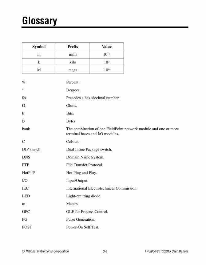
© National Instruments Corporation G-1 FP-2000/2010/2015 User Manual
Glossary
Symbol Prefix Value
m milli 10–3
k kilo 103
M mega 106
% Percent.
° Degrees.
0x Precedes a hexadecimal number.
Ω Ohms.
b Bits.
B Bytes.
bank The combination of one FieldPoint network module and one or moreterminal bases and I/O modules.
C Celsius.
DIP switch Dual Inline Package switch.
DNS Domain Name System.
FTP File Transfer Protocol.
HotPnP Hot Plug and Play.
I/O Input/Output.
IEC International Electrotechnical Commission.
LED Light-emitting diode.
m Meters.
OPC OLE for Process Control.
PG Pulse Generation.
POST Power-On Self Test.

Glossary
FP-2000/2010/2015 User Manual G-2 ni.com
PWM Pulse-Width Modulation. Generation of a pulse waveform with fixedfrequency and variable pulse width (duty cycle). PWM is used to controldiscrete devices such as DC motors and heaters by varying the pulse width(the ration of on time to off time).
subnet A set of systems whose IP addresses are configured such that they cancommunicate directly with one another. Data will not flow through anintermediate router.
TCP Transmission Control Protocol. A set of standard protocols forcommunicating across a single network or interconnected set of networks.TCP is for high-reliability transmissions.
UDP User Datagram Protocol. A set of standard protocols for communicatingacross a single network or interconnected set of networks. UDP is forlow-overhead transmissions.
V Volts.
VDC Volts direct current.
VI Virtual Instrument. A combination of hardware and/or software elements,typically used with a PC, that has the functionality of a classic stand-aloneinstrument.
W Watts.
© National Instruments Corporation I-1 FP-2000/2010/2015 User Manual
Index
Numerics100 Mbps LED, 4-5
AA LED, 4-5access permissions, 3-12ACTIVE LED, 4-5Application Builder
Application Settings tab, 5-10embedding LabVIEW VIs on the
FP-20xx, 5-8Installer Settings tab, 5-10Source Files tab, 5-10Target tab, 5-9VI Settings tab, 5-10
applications, embedded. See embeddedapplications on FP-20xx
BB LED, 4-5
CC LED, 4-5cables, Ethernet, 2-11, E-3calibration certificate, F-2channels
attributes, 3-10configuration, 3-9deadband, 3-9monitoring, 3-14output values, 3-9range, 3-9sending channel commands, 3-10
type, 3-9writing to an output, 3-15
cleaning your FP-20xx, 2-2Comm Resource configuration, 3-2, 3-12
troubleshooting browse errors, C-1configuration
channel configuration, 3-9Comm Resource configuration, 3-2,
3-12, C-1connecting to field devices, 2-15custom power-up configuration, 4-2devices and channels, 3-6HotPnP (Hot Plug and Play), 4-3overview, 1-4saving hardware configuration as power-up
state, 3-10saving system configuration, 3-14software configuration in FieldPoint
Explorer, 3-1troubleshooting software configuration
problems, C-1verification, 3-14
contacting National Instruments, F-2conventions used in the manual, ivcustomer
education, F-1professional services, F-1technical support, F-1
DD LED, 4-5data communication
100 Mbps LED, 4-5methods, 3-20
DataSocket, 3-22DataSocket data communication, 3-20deadband, 3-9
Index
FP-2000/2010/2015 User Manual I-2 ni.com
Declaration of Conformity, F-1diagnostic resources, F-1DIN rail mount. See installation, mounting
hardware on DIN railDIP switches, 4-6Disable VI switch, 4-6DNS address
choosing values, A-1configuring, 3-4resetting with Reset switch, B-1
documentationonline library, F-1
downloading files to the FP-20xx, 5-11downloading LabVIEW VIs to the
FP-20xx, 5-6drivers
instrument, F-1software, F-1
Eelectromagnetic compatibility
specifications, E-2embedded applications on FP-20xx, 4-1, 5-8,
5-10, C-4environmental specifications, E-2errors
I/O status shown in FieldPointExplorer, -14
runaway startup application, C-4STATUS LED, 4-4STATUS LED error indications
(table), C-4troubleshooting software configuration
problems, C-1Ethernet network
cable length (caution), 2-11cabling connections (table), E-3connecting FP-20xx to network, 2-11
connectionsACTIVE LED indicator, 4-5figure, 1-3LINK LED indicator, 4-5methods, 2-12
example code, F-1
Ffactory configuration, 3-10FieldPoint bank (definition), 1-2FieldPoint Explorer
configuring devices and channels, 3-6configuring the FP-20xx, 3-1downloading configuration to
FP-20xx, 3-14installation, 2-15monitoring I/O channels, 3-14saving configuration, 3-14saving configuration as power-up
state, 3-10troubleshooting No Modules Found, C-3verifying configuration, 3-14writing to an output channel, 3-15
FieldPoint safety information, 2-1FieldPoint software
See also FieldPoint Explorer; RemoteSystem Explorer
FTP download site, 1-3installation, 2-15OPC server, 3-19overview, 1-3
FieldPoint VIs, 3-17, 4-7file transfer capability, 5-11FP-20xx hardware
comment to identify FP-20xx, 3-4configurable power-up state, 4-3configuration in FieldPoint Explorer, 3-1connecting to network, 2-11data communication methods, 3-20DIP switches, 4-6
Index
© National Instruments Corporation I-3 FP-2000/2010/2015 User Manual
downloading configuration, 3-14embedded applications. See embedded
applications on FP-20xxfeature set, 4-1hardware watchdog, 5-11host names, A-3HotPnP (Hot Plug and Play), 4-3installation
connecting to network, 2-11mounting FP-20xx on DIN rail, 2-4mounting FP-20xx to panel, 2-7
internal clock, 3-5IP address, 3-3, A-1limiting host access to LabVIEW RT
engine, 5-4locking/unlocking configuration, 3-13network watchdog, 4-1overview, 1-1power supply to I/O modules, 2-14powering, 2-13
figure, 2-14powering up, 2-15resetting to factory settings, B-1RS-232 serial port, 4-7safety information, 2-1saving configuration as power-up
state, 3-10security settings, 3-12setup overview, 1-4snapshot feature, 4-2specifications, E-1targeting LabVIEW RT to the
FP-20xx, 5-1TCP/IP settings, A-4transferring files to and from
FP-20xx, 5-11using with host PC software
DataSocket communication, 3-20LabVIEW, 3-17LabVIEW Publish Data VI, 3-23LabVIEW serial VIs, 3-23
LabVIEW TCP and UDP VIs, 3-23LabWindows/CVI, 3-18Lookout, 3-16OPC server, 3-19overview, 3-16
FTPNational Instruments FTP site, 1-3RT Engine FTP server, 5-11
Ggateway IP address
choosing values, A-1configuring, 3-4resetting with Reset switch, B-1
Hhelp
professional services, F-1technical support, F-1
host access, limiting, 3-12host name, A-3
configuring, 3-4Hosts files
Windows 2000/NT/XP, A-3Windows 98/95, A-3
HotPnP (Hot Plug and Play)I/O module configuration after HotPnP
replacement (table), 4-4overview, 4-3
II/O modules
configurable power-up state, 4-3configuration, 3-6configuration after HotPnP replacement
(table), 4-4connecting to field devices, 2-15inserting, 4-3
Index
FP-2000/2010/2015 User Manual I-4 ni.com
monitoring channels, 3-14mounting on terminal bases, 2-10No Modules Found error, C-3powering, 2-13, 2-14removing, 2-11, 4-3replacing, 4-3resetting, B-1saving configuration as power-up
state, 3-10writing to an output channel, 3-15
iak file, 3-14icon, 3-11, 3-14, 3-15installation
category, 2-2connecting to network, 2-11FieldPoint software, 2-15, D-1HotPnP (Hot Plug and Play), 4-3LabVIEW RT, 2-15, D-1mounting hardware on DIN rail
connecting terminal bases, 2-6mounting FP-20xx, 2-4removing FP-20xx and terminal
bases, 2-6mounting hardware to a panel
connecting terminal bases, 2-8FP-20xx mounting procedure, 2-7panel mount accessory, 2-7, 2-8panel mount accessory (figure), 2-8removing FP-20xx and terminal
bases, 2-10mounting I/O modules onto terminal
bases, 2-10overview, 1-4power connections, 2-13, 2-14
figure, 2-14removing I/O modules, 2-11
Installer Settings tab in ApplicationBuilder, 5-10
instrument drivers, F-1IP Access List, 3-12, 3-13
IP addressSee also gateway IP address; DNS
address; time server; subnet maskchoosing, A-1configuring, 3-3error when configuring, C-2resetting with Reset switch, 4-7, B-1
IP Pattern, 3-13isolation
defeated by cascading powercaution, 2-13figure, 2-14
KKnowledgeBase, F-1
LLabVIEW RT
See also Application Builderdisabling engine with Safe Mode
switch, 4-7embedded applications. See embedded
applications on FP-20xxinstallation, D-1network options, 5-3programming, 5-1RT Engine, 1-1, 4-7, 5-3, 5-4, 5-8, 5-11RT Target Access options, 5-4RT Target Miscellaneous options, 5-6targeting LabVIEW RT
to a platform, 5-1to host PC, 5-3
LabVIEW VIsDisable VI switch, 4-6embedded applications. See embedded
applications on FP-20xxFieldPoint VIs, 3-17hardware watchdog VIs, 5-11LabVIEW FieldPoint VIs, 4-7
Index
© National Instruments Corporation I-5 FP-2000/2010/2015 User Manual
launching VIs at system startup, 5-6, 5-10Publish Data VI, 3-23runaway startup applications, C-4serial VIs, 3-23specifying download path, 5-6specifying target with command line
arguments, 5-7TCP, 3-23UDP VIs, 3-23
LabWindows/CVI software, 3-18LED indicators, 4-4
power-on self test (POST), 2-15, 4-5LINK LED, 4-5local bus connector, protective cover (figure),
2-6, 2-10Lookout software, 3-16
M100 Mbps LED, 4-5memory specifications, E-1modules. See FP-20xx hardware; I/O modulesmonitoring I/O channels, 3-14mounting hardware on DIN rail. See
installation, mounting hardware on DIN railmounting hardware to a panel. See installation,
mounting hardware to a panel
NNational Instruments
calibration certificate, F-2customer education, F-1Declaration of Conformity, F-1professional services, F-1system integration services, F-1technical support, F-1worldwide offices, F-2
network module. See FP-20xx hardwarenetwork security settings, 3-12network specifications, E-1
network watchdog, 4-1network. See Ethernet network
Oonline technical support, F-1OPC client, 3-19, 3-20OPC server, 3-19, 3-20overview
FieldPoint software, 1-3FP-20xx hardware, 1-1setup, 1-4using FP-20xx from host
applications, 3-16
Ppanel mount. See installation, mounting
hardware to a panelpassword, locking/unlocking configuration in
Remote System Explorer, 3-13password-protected resets, 3-4, B-1phone technical support, F-2physical characteristic specifications, E-2pollution degree, 2-2power connections
calculating power for FieldPointbank, 2-14
figure, 2-14wiring, 2-13
POWER LED, 4-4power requirement specifications, E-1power supply, 2-13power-on self test (POST), 2-15, 4-5power-up
launching LabVIEW RT applications atsystem startup, 5-6, 5-10
overview, 2-15runaway startup applications, C-4
power-up state, configurable, 4-3
Index
FP-2000/2010/2015 User Manual I-6 ni.com
professional services, F-1programming examples, F-1
Rrail clip, 2-4, 2-7registering computers
with Lookout, 3-16with OPC, 3-19
Remote System Explorerfeatures and options, 3-11locking/unlocking configuration, 3-13troubleshooting browse errors, C-1troubleshooting No Software Installed
status, C-3removing FP-20xx and terminal bases
DIN rail mount, 2-6panel mount, 2-10
Reset switch, 4-7, B-1resetting a FieldPoint bank, 3-4, 4-7, 5-11, B-1RS-232 serial port, 1-1, 3-23, 4-7RT Engine. See LabVIEW RT; RT EngineRT Target Access options, 5-4RT Target Miscellaneous options, 5-6
Ssafe mode, 4-7Safe Mode switch, 4-7safety information, 2-1safety specifications, E-2saving current state of FieldPoint bank, 4-2saving system configuration, 3-14security
locking/unlocking Remote SystemExplorer settings, 3-13
network security settings, 3-12password-protected resets, 3-4
serial data communication, 3-23serial port, 1-1, 3-23, 4-7serial VIs, 4-7
snapshot feature, 3-10, 4-2software drivers, F-1specifications
cabling, E-3electromagnetic compatibility, E-2environmental, E-2memory, E-1network, E-1physical characteristics, E-2power requirements, E-1safety, E-2
STATUS LED, 4-4STATUS LED error indications (table), C-4subnet mask
choosing values, A-1, A-2configuring, 3-3resetting with Reset switch, B-1
supporttechnical, F-1
switchesDIP switches, 4-6DIP switches 1 through 5, 4-7
system integration services, F-1
TTCP data communication, 3-23TCP/IP settings, A-4technical support, F-1telephone technical support, F-2terminal bases
connecting with DIN rail mount, 2-6connecting with panel mount, 2-8powering, 2-13removing with DIN rail mount, 2-6removing with panel mount, 2-10
testingpower-on self test (POST), 4-5verifying configuration in FieldPoint
Explorer, 3-14
Index
© National Instruments Corporation I-7 FP-2000/2010/2015 User Manual
time serverchoosing IP address, A-1configuring IP address, 3-5resetting with Reset switch, B-1setting FP-20xx internal clock, 3-5
timestampshown in FieldPoint Explorer, 3-14troubleshooting invalid values, C-2
trainingcustomer, F-1
troubleshootingComm Resource Configuration dialog
box errors, C-1invalid timestamp values, C-2IP configuration errors, C-2No Modules Found error, C-3No Software Installed status, C-3Remote System Explorer browse
errors, C-1runaway startup applications, C-4STATUS LED error indications
(table), C-4troubleshooting resources, F-1
UUDP data communication, 3-23upgrading software on the FP-20xx, D-1
VVIs. See LabVIEW VIs
Wwatchdog, 4-1, 5-11Web
professional services, F-1technical support, F-1
wiringEthernet cables, E-3Ethernet connections, 2-12field devices, 2-15power, 2-13power (figure), 2-14
worldwide technical support, F-2writing to an output channel, 3-15