Embed Size (px)
Citation preview
Arduino Traffic Lights By: Nabeela Merchant Duration: 60 minutes
LEVEL SUBJECTS PROVINCES / TERRITORIES TOOL
Grades 9-12 Science and Technology; Applied Design, Skills, and Technologies
Across Canada, BC Arduino
Overview Key Coding Concepts
In this activity you’ll create a working model of a traffic
light using an Arduino Uno microcontroller and some
electronics.
Prep Work ● Complete the “Morse Code with Arduino”
Lesson first. Make sure your Arduino CreateEditor account is set up and works with theArduino Uno:https://www.canadalearningcode.ca/lessons/morse-code-with-arduino/
● Read this primer on circuits:https://learn.sparkfun.com/tutorials/what-is-a-circuit
● Work through the example project to getfamiliar with the hardware and software andensure everything is working correctly:http://bit.ly/arduino-traffic-light-eg
● Go over the slides for the lesson:http://bit.ly/arduino-traffic-light-slides
Variables
Functions
Loops
Terminology
Breadboard
A board used to build electric
circuit models.
Resistor
A component that regulates the
flow of an electric circuit.
LED
A light-emitting diode (LED)
emits visible light when an
electric circuit passes through
it.
1

● Print the solutions sheet: http://bit.ly/arduino-traffic-light-solution
Materials (per pair):
● Laptop with administrator permissions ● Arduino Create account ● Arduino Uno ● A B USB cable (USB printer cable) to connect the
the Arduino Uno to the laptop ● Some basic electronics:
○ Breadboard ○ Wires ○ 1000 ohm resistors x3 ○ A red, yellow, and green LED
Lesson Use the following slides for this lesson: http://bit.ly/arduino-traffic-light-slides Introduction Traffic lights are used all over the world to control the flow of traffic. The first traffic light was installed in London in 1868, before cars were created, to control the movement of horse carriages in the area, so pedestrians could safely cross the road. These original traffic lights had only two colours, red for stop and green for go. The three coloured traffic lights we know today weren’t introduced till 1920.
Curricular Connections
Text-based coding, digital
output devices, electronics,
components of an electric
circuit, electrical components,
PCB (printed circuit boards),
input/output devices,
microcontrollers,
communication, impacts of
technology on societies
References
Arduino Create
https://create.arduino.cc/
Arduino Uno
https://store.arduino.cc/usa/ar
duino-uno-rev3
Arduino Reference
https://www.arduino.cc/referen
ce/en/
Traffic lights are great examples of simple robotic systems that have had profound effects on society. Using the Arduino Uno and a simple circuit, we will create a model of a three coloured traffic light. The circuit will consist of three lights, green; yellow; and red, that are each connected to the Arduino Uno. The traffic light will be green for 5 seconds, yellow for 1.5 seconds, and red for 3 seconds. Code Along Open up the example project and show learners the code and physical output (blinking LED on a circuit board).
2
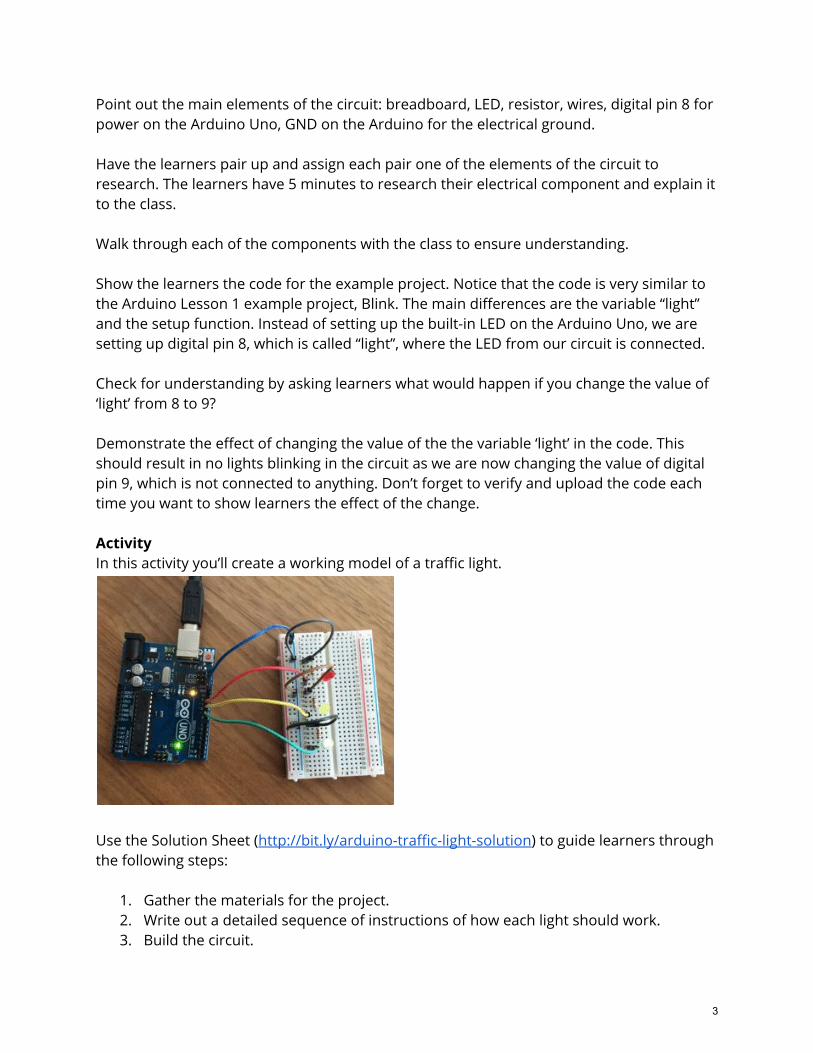
Point out the main elements of the circuit: breadboard, LED, resistor, wires, digital pin 8 for power on the Arduino Uno, GND on the Arduino for the electrical ground. Have the learners pair up and assign each pair one of the elements of the circuit to research. The learners have 5 minutes to research their electrical component and explain it to the class. Walk through each of the components with the class to ensure understanding. Show the learners the code for the example project. Notice that the code is very similar to the Arduino Lesson 1 example project, Blink. The main differences are the variable “light” and the setup function. Instead of setting up the built-in LED on the Arduino Uno, we are setting up digital pin 8, which is called “light”, where the LED from our circuit is connected. Check for understanding by asking learners what would happen if you change the value of ‘light’ from 8 to 9? Demonstrate the effect of changing the value of the the variable ‘light’ in the code. This should result in no lights blinking in the circuit as we are now changing the value of digital pin 9, which is not connected to anything. Don’t forget to verify and upload the code each time you want to show learners the effect of the change. Activity In this activity you’ll create a working model of a traffic light.
Use the Solution Sheet (http://bit.ly/arduino-traffic-light-solution) to guide learners through the following steps:
1. Gather the materials for the project. 2. Write out a detailed sequence of instructions of how each light should work. 3. Build the circuit.
3
4. Connect the Arduino Uno to the computer. 5. Open up the Traffic Light project 6. Fill out the remaining commands to turn on and off the lights in the right order. 7. Check the code. 8. Verify and upload the code to the Arduino Uno.
Assessment ● After reviewing the example project, co-construct success criteria with the class to
be used to evaluate their final projects. ● Have learners research the following programming concepts and explain how they
used them in their project: Variables, Functions, Loops
Extensions Program a 4 stage traffic light with the following pattern:
● Red for 3 seconds ● Red and yellow for 1.5 seconds ● Green for 5 seconds ● Yellow for 1.5 seconds
These four stage traffic lights are used in Britain and use the same 3 colours while letting drivers know when the light will turn green.
4
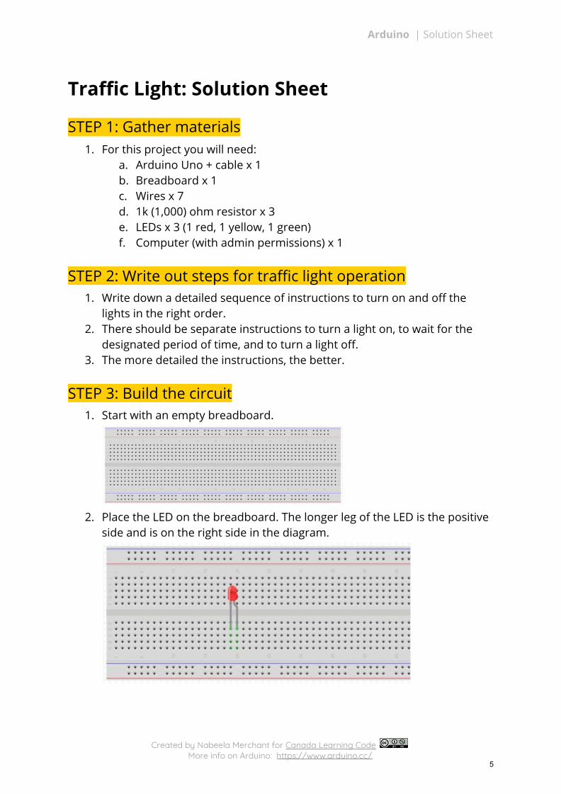
Arduino | Solution Sheet
Traffic Light: Solution Sheet
STEP 1: Gather materials 1. For this project you will need:
a. Arduino Uno + cable x 1 b. Breadboard x 1 c. Wires x 7 d. 1k (1,000) ohm resistor x 3 e. LEDs x 3 (1 red, 1 yellow, 1 green) f. Computer (with admin permissions) x 1
STEP 2: Write out steps for traffic light operation 1. Write down a detailed sequence of instructions to turn on and off the
lights in the right order. 2. There should be separate instructions to turn a light on, to wait for the
designated period of time, and to turn a light off. 3. The more detailed the instructions, the better.
STEP 3: Build the circuit 1. Start with an empty breadboard.
2. Place the LED on the breadboard. The longer leg of the LED is the positive
side and is on the right side in the diagram.
Created by Nabeela Merchant for Canada Learning Code More info on Arduino: https://www.arduino.cc/
5
Arduino | Solution Sheet
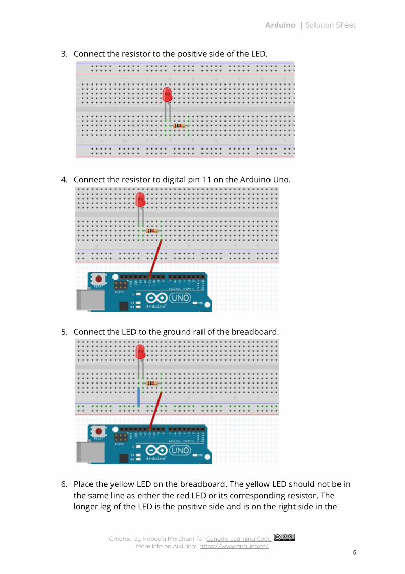
3. Connect the resistor to the positive side of the LED.
4. Connect the resistor to digital pin 11 on the Arduino Uno.
5. Connect the LED to the ground rail of the breadboard.
6. Place the yellow LED on the breadboard. The yellow LED should not be in the same line as either the red LED or its corresponding resistor. The longer leg of the LED is the positive side and is on the right side in the
Created by Nabeela Merchant for Canada Learning Code More info on Arduino: https://www.arduino.cc/
6
Arduino | Solution Sheet
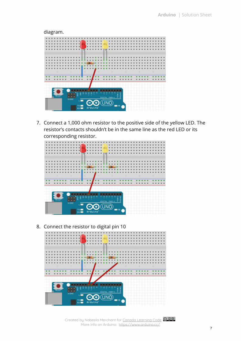
diagram.
7. Connect a 1,000 ohm resistor to the positive side of the yellow LED. The resistor’s contacts shouldn’t be in the same line as the red LED or its corresponding resistor.
8. Connect the resistor to digital pin 10
Created by Nabeela Merchant for Canada Learning Code More info on Arduino: https://www.arduino.cc/
7
Arduino | Solution Sheet
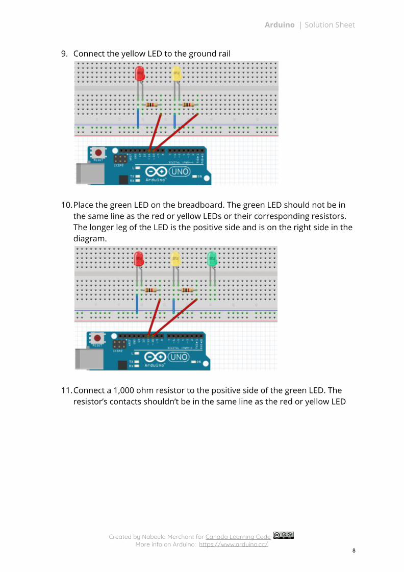
9. Connect the yellow LED to the ground rail
10.Place the green LED on the breadboard. The green LED should not be in the same line as the red or yellow LEDs or their corresponding resistors. The longer leg of the LED is the positive side and is on the right side in the diagram.
11.Connect a 1,000 ohm resistor to the positive side of the green LED. The resistor’s contacts shouldn’t be in the same line as the red or yellow LED
Created by Nabeela Merchant for Canada Learning Code More info on Arduino: https://www.arduino.cc/
8
Arduino | Solution Sheet
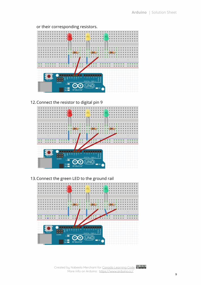
or their corresponding resistors.
12.Connect the resistor to digital pin 9
13.Connect the green LED to the ground rail
Created by Nabeela Merchant for Canada Learning Code More info on Arduino: https://www.arduino.cc/
9
Arduino | Solution Sheet
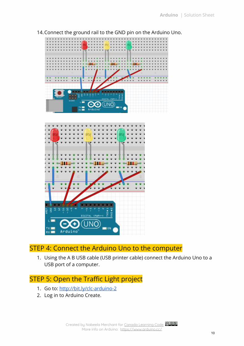
14.Connect the ground rail to the GND pin on the Arduino Uno.
STEP 4: Connect the Arduino Uno to the computer 1. Using the A B USB cable (USB printer cable) connect the Arduino Uno to a
USB port of a computer.
STEP 5: Open the Traffic Light project
1. Go to: http://bit.ly/clc-arduino-2 2. Log in to Arduino Create.
Created by Nabeela Merchant for Canada Learning Code More info on Arduino: https://www.arduino.cc/
10
Arduino | Solution Sheet
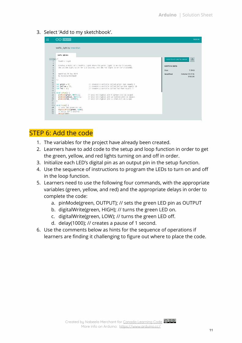
3. Select ‘Add to my sketchbook’.
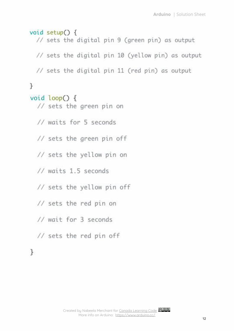
STEP 6: Add the code 1. The variables for the project have already been created. 2. Learners have to add code to the setup and loop function in order to get
the green, yellow, and red lights turning on and off in order. 3. Initialize each LED’s digital pin as an output pin in the setup function. 4. Use the sequence of instructions to program the LEDs to turn on and off
in the loop function. 5. Learners need to use the following four commands, with the appropriate
variables (green, yellow, and red) and the appropriate delays in order to complete the code:
a. pinMode(green, OUTPUT); // sets the green LED pin as OUTPUT b. digitalWrite(green, HIGH); // turns the green LED on. c. digitalWrite(green, LOW); // turns the green LED off. d. delay(1000); // creates a pause of 1 second.
6. Use the comments below as hints for the sequence of operations if learners are finding it challenging to figure out where to place the code.
Created by Nabeela Merchant for Canada Learning Code More info on Arduino: https://www.arduino.cc/
11
Arduino | Solution Sheet
Created by Nabeela Merchant for Canada Learning Code More info on Arduino: https://www.arduino.cc/
12
Arduino | Solution Sheet
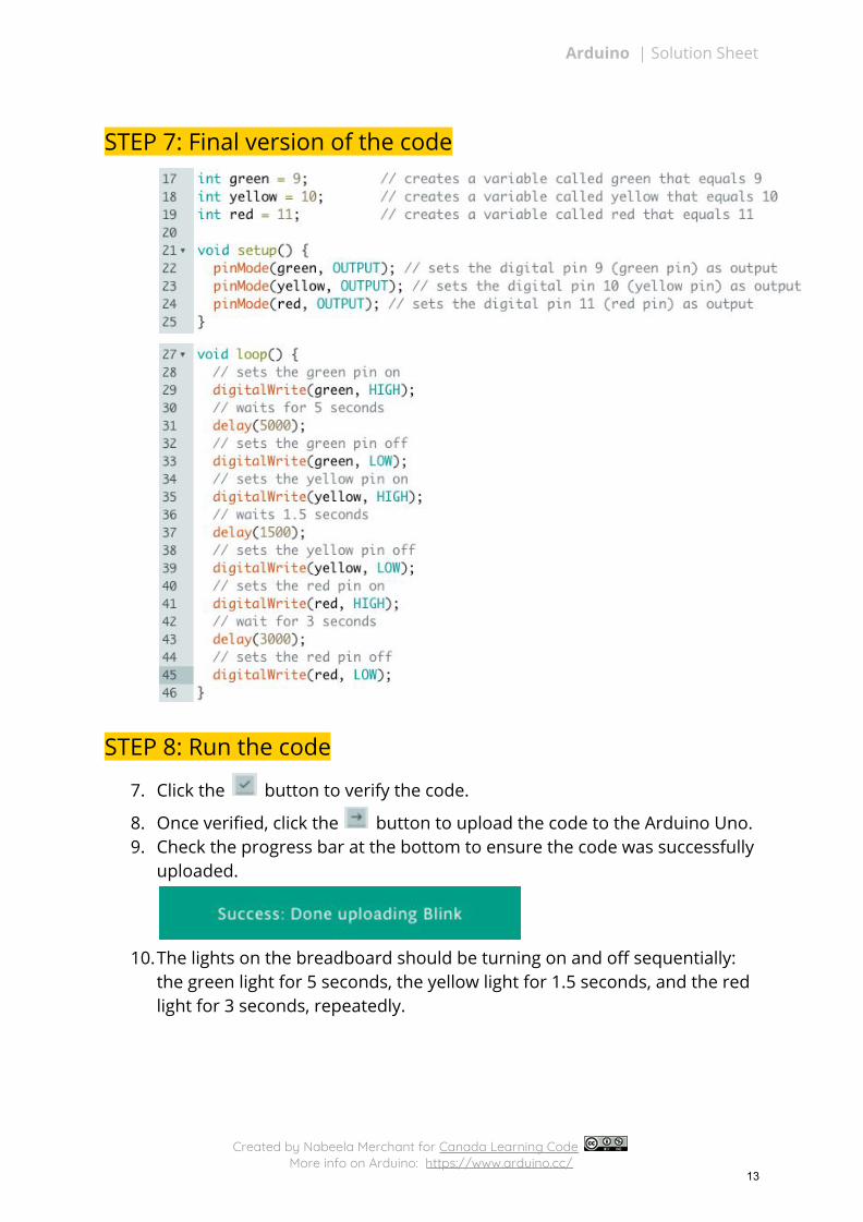
STEP 7: Final version of the code
STEP 8: Run the code
7. Click the button to verify the code.
8. Once verified, click the button to upload the code to the Arduino Uno. 9. Check the progress bar at the bottom to ensure the code was successfully
uploaded.
10.The lights on the breadboard should be turning on and off sequentially:
the green light for 5 seconds, the yellow light for 1.5 seconds, and the red light for 3 seconds, repeatedly.
Created by Nabeela Merchant for Canada Learning Code More info on Arduino: https://www.arduino.cc/
13
Arduino | Solution Sheet
Traffic Light: Example Project
STEP 1: Gather materials 1. For this project you will need:
a. Arduino Uno + cable x 1 b. Breadboard x 1 c. Wires x 3 d. 1k (1,000) ohm resistor x 1 e. LED x 1 f. Computer (with admin permissions) x 1
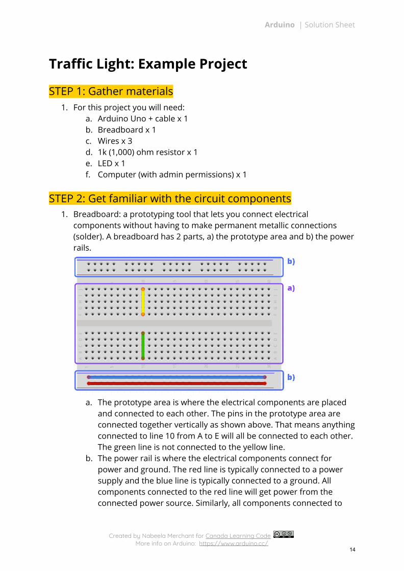
STEP 2: Get familiar with the circuit components 1. Breadboard: a prototyping tool that lets you connect electrical
components without having to make permanent metallic connections (solder). A breadboard has 2 parts, a) the prototype area and b) the power rails.
a. The prototype area is where the electrical components are placed
and connected to each other. The pins in the prototype area are connected together vertically as shown above. That means anything connected to line 10 from A to E will all be connected to each other. The green line is not connected to the yellow line.
b. The power rail is where the electrical components connect for power and ground. The red line is typically connected to a power supply and the blue line is typically connected to a ground. All components connected to the red line will get power from the connected power source. Similarly, all components connected to
Created by Nabeela Merchant for Canada Learning Code More info on Arduino: https://www.arduino.cc/
14
Arduino | Solution Sheet
the blue line will be grounded through the common ground that is connected to the blue line.
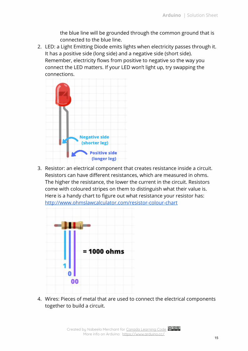
2. LED: a Light Emitting Diode emits lights when electricity passes through it. It has a positive side (long side) and a negative side (short side). Remember, electricity flows from positive to negative so the way you connect the LED matters. If your LED won’t light up, try swapping the connections.
3. Resistor: an electrical component that creates resistance inside a circuit.
Resistors can have different resistances, which are measured in ohms. The higher the resistance, the lower the current in the circuit. Resistors come with coloured stripes on them to distinguish what their value is. Here is a handy chart to figure out what resistance your resistor has: http://www.ohmslawcalculator.com/resistor-colour-chart
4. Wires: Pieces of metal that are used to connect the electrical components
together to build a circuit.
Created by Nabeela Merchant for Canada Learning Code More info on Arduino: https://www.arduino.cc/
15
Arduino | Solution Sheet
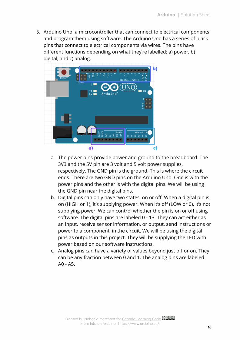
5. Arduino Uno: a microcontroller that can connect to electrical components and program them using software. The Arduino Uno has a series of black pins that connect to electrical components via wires. The pins have different functions depending on what they’re labelled: a) power, b) digital, and c) analog.
a. The power pins provide power and ground to the breadboard. The
3V3 and the 5V pin are 3 volt and 5 volt power supplies, respectively. The GND pin is the ground. This is where the circuit ends. There are two GND pins on the Arduino Uno. One is with the power pins and the other is with the digital pins. We will be using the GND pin near the digital pins.
b. Digital pins can only have two states, on or off. When a digital pin is on (HIGH or 1), it’s supplying power. When it’s off (LOW or 0), it’s not supplying power. We can control whether the pin is on or off using software. The digital pins are labeled 0 - 13. They can act either as an input, receive sensor information, or output, send instructions or power to a component, in the circuit. We will be using the digital pins as outputs in this project. They will be supplying the LED with power based on our software instructions.
c. Analog pins can have a variety of values beyond just off or on. They can be any fraction between 0 and 1. The analog pins are labeled A0 - A5.
Created by Nabeela Merchant for Canada Learning Code More info on Arduino: https://www.arduino.cc/
16
Arduino | Solution Sheet
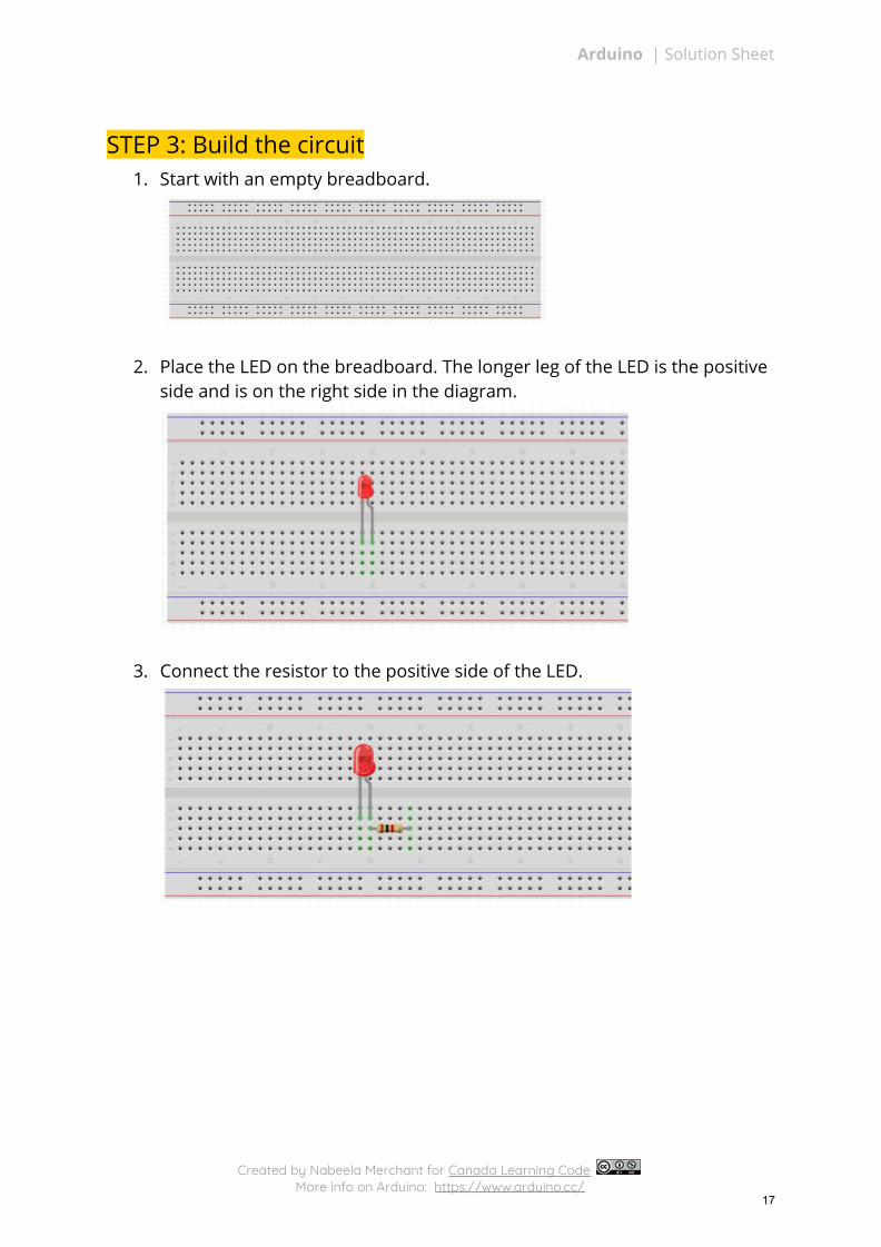
STEP 3: Build the circuit 1. Start with an empty breadboard.
2. Place the LED on the breadboard. The longer leg of the LED is the positive side and is on the right side in the diagram.
3. Connect the resistor to the positive side of the LED.
Created by Nabeela Merchant for Canada Learning Code More info on Arduino: https://www.arduino.cc/
17
Arduino | Solution Sheet
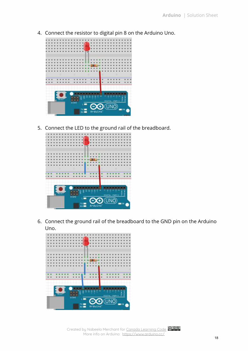
4. Connect the resistor to digital pin 8 on the Arduino Uno.
5. Connect the LED to the ground rail of the breadboard.
6. Connect the ground rail of the breadboard to the GND pin on the Arduino Uno.
Created by Nabeela Merchant for Canada Learning Code More info on Arduino: https://www.arduino.cc/
18
Arduino | Solution Sheet
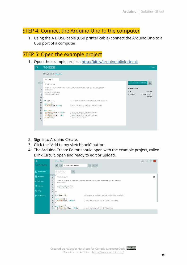
STEP 4: Connect the Arduino Uno to the computer 1. Using the A B USB cable (USB printer cable) connect the Arduino Uno to a
USB port of a computer.
STEP 5: Open the example project 1. Open the example project: http://bit.ly/arduino-blink-circuit
2. Sign into Arduino Create. 3. Click the “Add to my sketchbook” button. 4. The Arduino Create Editor should open with the example project, called
Blink Circuit, open and ready to edit or upload.
Created by Nabeela Merchant for Canada Learning Code More info on Arduino: https://www.arduino.cc/
19
Arduino | Solution Sheet
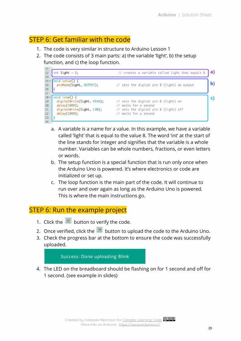
STEP 6: Get familiar with the code 1. The code is very similar in structure to Arduino Lesson 1 2. The code consists of 3 main parts: a) the variable ‘light’, b) the setup
function, and c) the loop function.
a. A variable is a name for a value. In this example, we have a variable
called ‘light’ that is equal to the value 8. The word ‘int’ at the start of the line stands for integer and signifies that the variable is a whole number. Variables can be whole numbers, fractions, or even letters or words.
b. The setup function is a special function that is run only once when the Arduino Uno is powered. It’s where electronics or code are initialized or set up.
c. The loop function is the main part of the code. It will continue to run over and over again as long as the Arduino Uno is powered. This is where the main instructions go.
STEP 6: Run the example project
1. Click the button to verify the code.
2. Once verified, click the button to upload the code to the Arduino Uno. 3. Check the progress bar at the bottom to ensure the code was successfully
uploaded.
4. The LED on the breadboard should be flashing on for 1 second and off for
1 second. (see example in slides)
Created by Nabeela Merchant for Canada Learning Code More info on Arduino: https://www.arduino.cc/
20