Embed Size (px)
Citation preview
Using Your Arduino, Breadboard and Multimeter
1

2
The content of this presentation is for informational purposes only and is intended only for students attending Louisiana Tech University.
The author of this information does not make any claims as to the validity or accuracy of the information or methods presented.
Any procedures demonstrated here are potentially dangerous and could result in injury or damage.
Louisiana Tech University and the State of Louisiana, their officers, employees, agents or volunteers, are not liable or responsible for any injuries, illness, damage or losses which may result from your using the materials or ideas, or from your performing the experiments or procedures depicted in this presentation.
If you do not agree, then do not view this content.
The copyright label, the Louisiana Tech logo, and the “living with the lab” identifier should not be removed from this presentation.
You may modify this work for your own purposes as long as attribution is clearly provided.
DISCLAIMER & USAGE
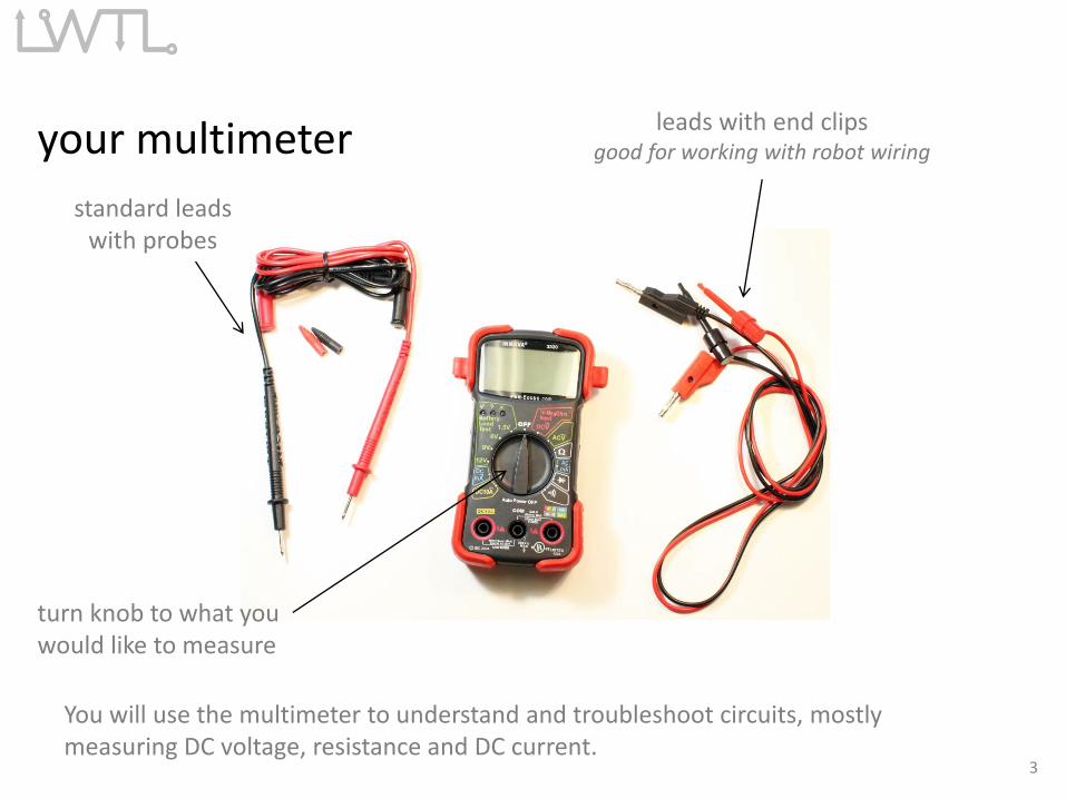
your multimeter
standard leadswith probes
You will use the multimeter to understand and troubleshoot circuits, mostlymeasuring DC voltage, resistance and DC current.
turn knob to what youwould like to measure
leads with end clipsgood for working with robot wiring
3
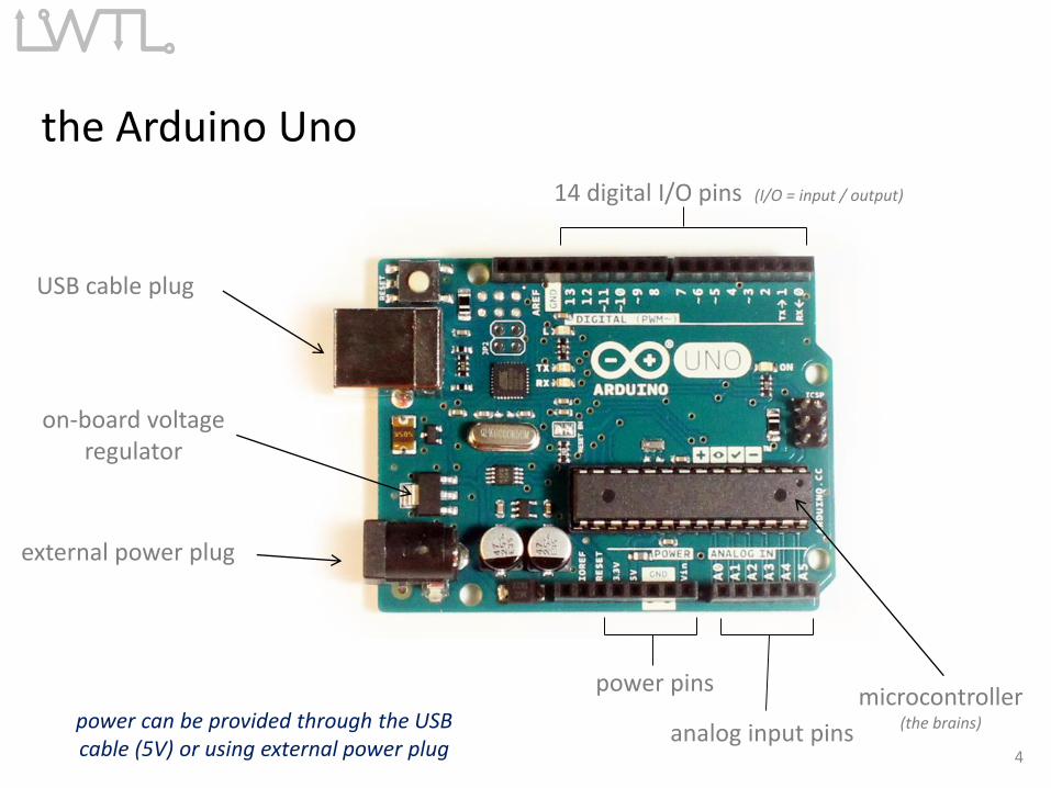
the Arduino Uno
USB cable plug
external power plug
14 digital I/O pins (I/O = input / output)
microcontroller(the brains)power can be provided through the USB
cable (5V) or using external power plug
power pins
on-board voltageregulator
analog input pins4
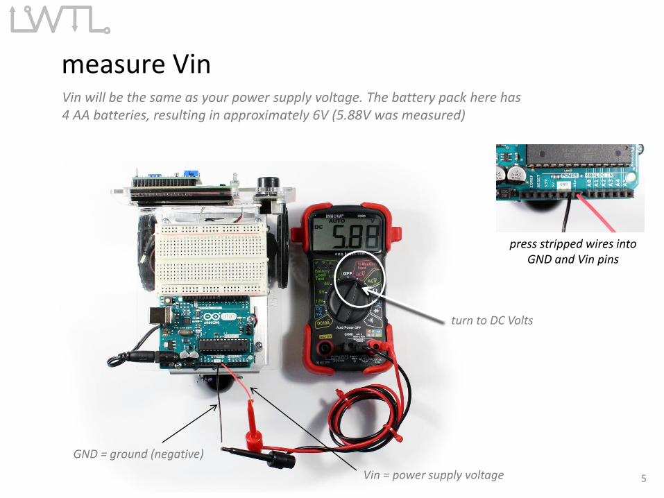
measure VinVin will be the same as your power supply voltage. The battery pack here has4 AA batteries, resulting in approximately 6V (5.88V was measured)
turn to DC Volts
GND = ground (negative)
Vin = power supply voltage 5
press stripped wires intoGND and Vin pins
turn to DC Volts
GND = ground (negative)
6
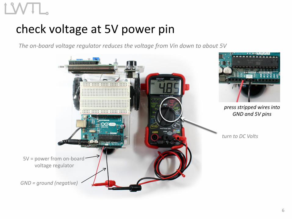
press stripped wires intoGND and 5V pins
check voltage at 5V power pinThe on-board voltage regulator reduces the voltage from Vin down to about 5V
5V = power from on-board voltage regulator
turn to DC Volts
GND = ground (negative)
7
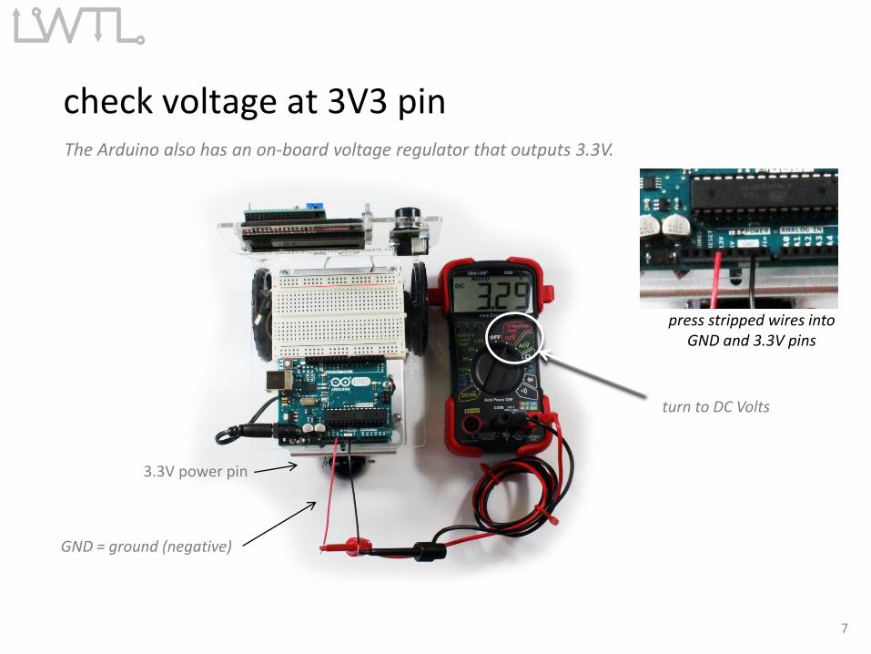
press stripped wires intoGND and 3.3V pins
3.3V power pin
check voltage at 3V3 pinThe Arduino also has an on-board voltage regulator that outputs 3.3V.
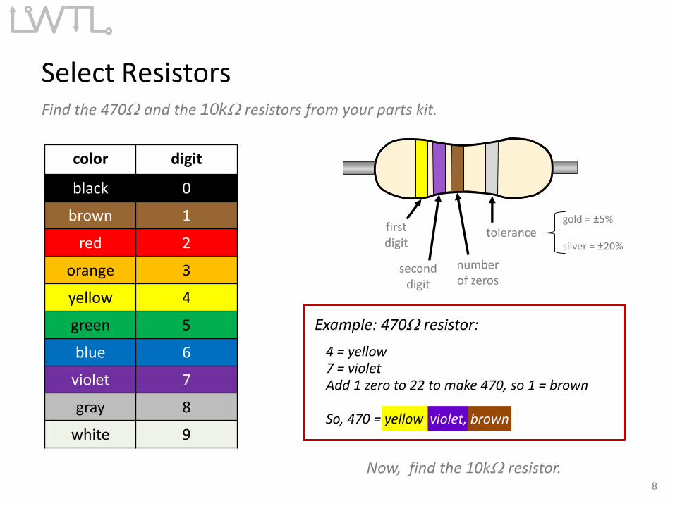
Select Resistors Find the 470W and the 10kW resistors from your parts kit.
Now, find the 10kW resistor.
Example: 470W resistor:
4 = yellow7 = violetAdd 1 zero to 22 to make 470, so 1 = brown
So, 470 = yellow, violet, brown
color digit
black 0
brown 1
red 2
orange 3
yellow 4
green 5
blue 6
violet 7
gray 8
white 9
firstdigit
seconddigit
numberof zeros
tolerancegold = ±5%
silver = ±20%
8

R = 4.62kW
Check Resistance of Resistors
470W resistor
9
set multimeter tomeasure W
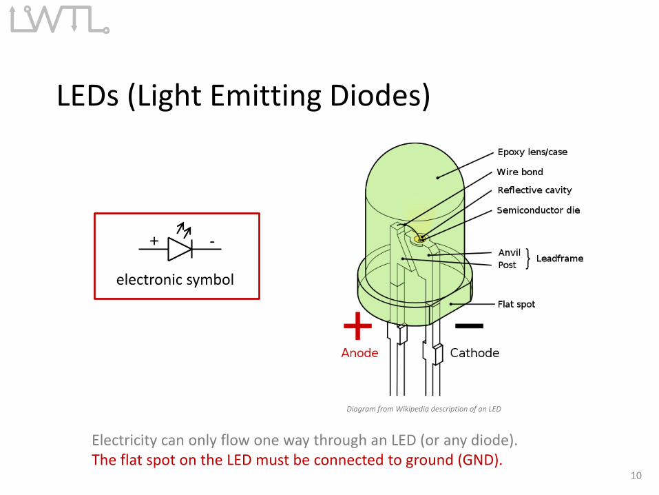
LEDs (Light Emitting Diodes)
Electricity can only flow one way through an LED (or any diode). The flat spot on the LED must be connected to ground (GND).
Diagram from Wikipedia description of an LED
electronic symbol
+ -
10
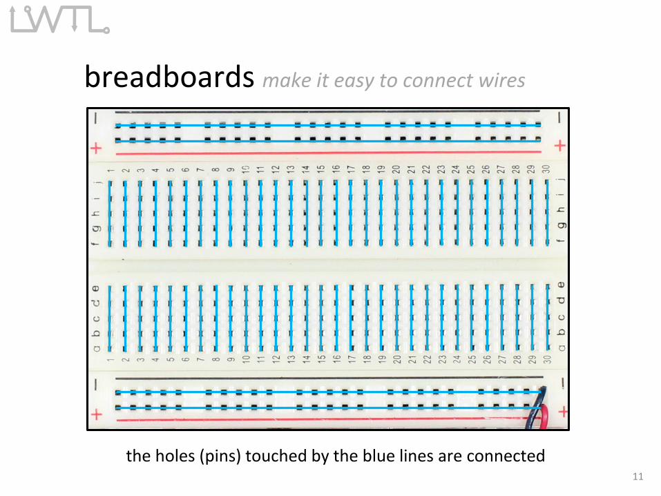
the holes (pins) touched by the blue lines are connected11
breadboards make it easy to connect wires
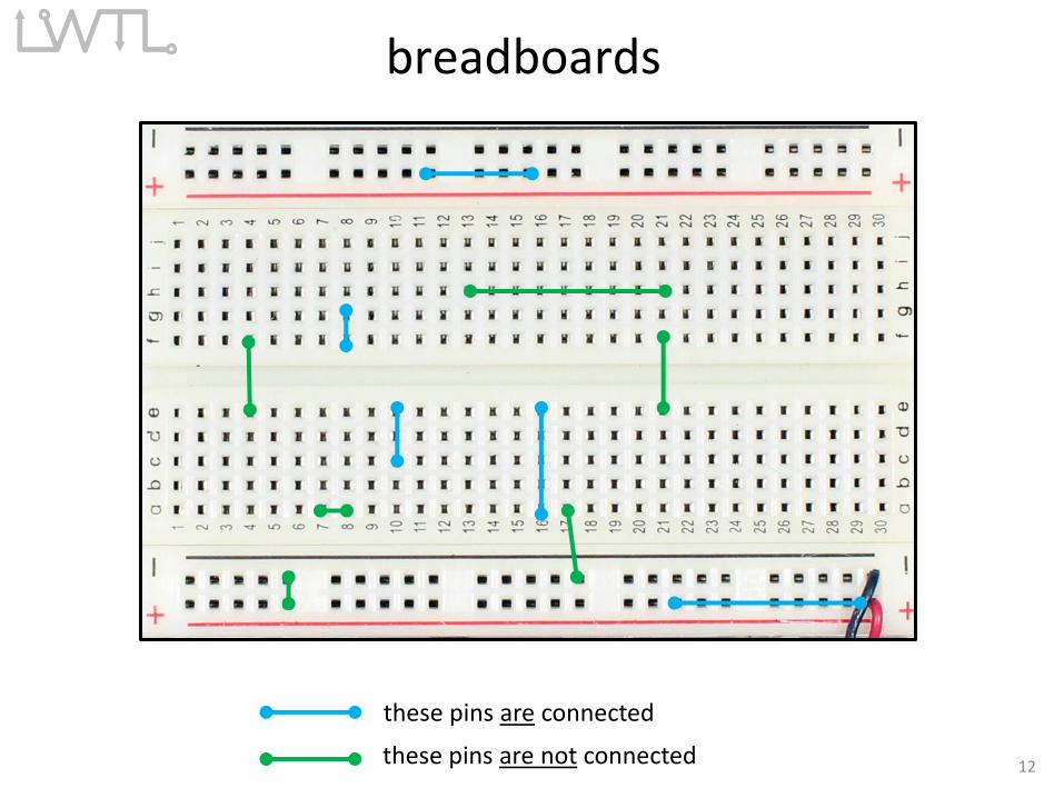
breadboards
12
these pins are connected
these pins are not connected
13
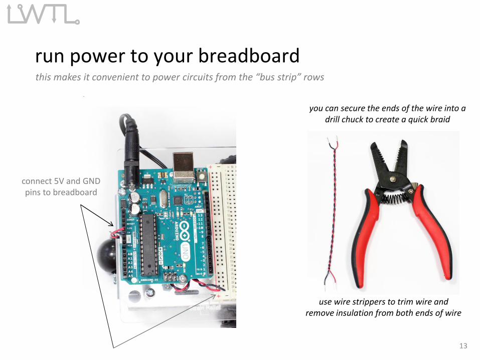
connect 5V and GNDpins to breadboard
run power to your breadboardthis makes it convenient to power circuits from the “bus strip” rows
use wire strippers to trim wire and remove insulation from both ends of wire
you can secure the ends of the wire into a drill chuck to create a quick braid
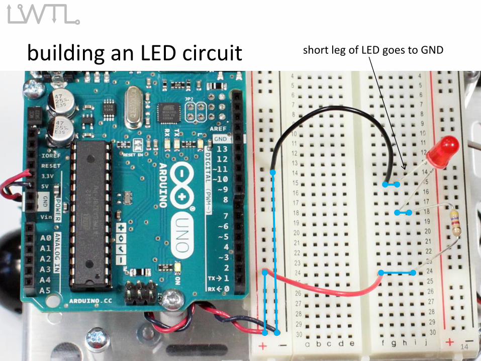
building an LED circuit
14
short leg of LED goes to GND
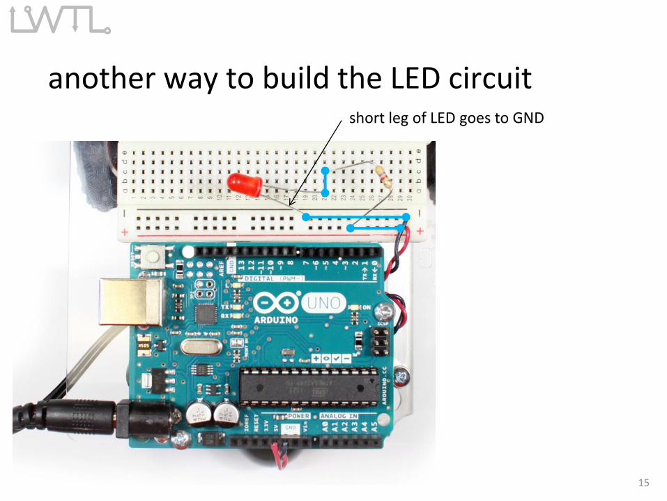
another way to build the LED circuit
15
short leg of LED goes to GND
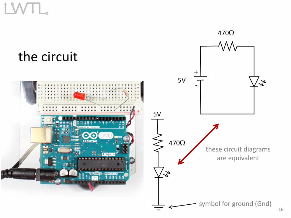
the circuit
5V+
-
470W
470W
5V
these circuit diagramsare equivalent
symbol for ground (Gnd)16
Replace the 470 W Resistor with the 10kW ResistorWhat happens and Why??
ANSWER: The smaller resistor (470W) provides less resistance to current thanthe larger resistor (10kW). Since more current passes through the smallerresistor, more current also passes through the LED making it brighter.
What would happen if you forgot to put in a resistor? You would probably burn up your LED.
17
The End